Embed Size (px)
Citation preview
21/06/2021
1
GC2020-2021
On the design of campus networks for High Availability
1
GC2020-2021
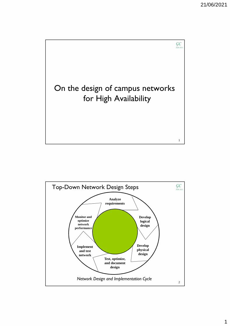
Top-Down Network Design Steps
Analyze requirements
Develop logical design
Develop physical design
Test, optimize, and document
design
Monitor and optimize network
performance
Implement and test network
Network Design and Implementation Cycle2

21/06/2021
2
GC2020-2021
Network Design Steps
� Phase 1- Analyze Requirements
� Analyze business goals and constraints
� Analyze technical goals and tradeoffs
� Characterize the existing network
� Characterize (current and future) network traffic
3
GC2020-2021
Network Design Steps
� Phase 2 – Logical Network Design
� Design a network topology
� Design models for addressing and naming
� Select routing protocols
� Develop network security strategies
� Develop network management strategies
4

21/06/2021
3
GC2020-2021
Network Design Steps
� Phase 3 – Physical Network Design
� Select technologies and devices for campus networks
� Select technologies and devices for enterprise WAN networks
5
GC2020-2021Network Design Steps
� Phase 4 – Testing, Optimizing, and Documenting the Network Design
� Test the network design
� Optimize the network design
� Document the network design
6

21/06/2021
4
GC2020-2021Network requirements
� Most businesses actually have only a few requirements for their network:
� The network should stay up all the time, even in the event of failed links, and equipment failures
� The network should reliably deliver applications and provide reasonable response times
� Mobile users must be supported
� The network should be secure
� The network should be easy to modify to adapt to network growth and general business changes
� Manageability and troubleshooting should be easy. Finding and fixing a problem should not be too time-consuming
7
GC2020-2021Design for fault-tolerance
� Backbone redundancy
� Device redundancy
� In-the-box redundancy
� Network Interface redundancy
� Dual Station (tandem) and Cluster Systems
The fault-tolerant solution must be as simple as possible and should contain the minimum redundancy such that an alternative path for data is ensured
8

21/06/2021
5
GC2020-2021
First hop redundancy: HSRP
� Hot Standby Router Protocol (HSRP) is proprietary (Cisco)� HSRP works by creating a virtual router
� The virtual router has its own IP and MAC addresses
� Each hosts is configured to use the virtual router as its default router (also named default gateway)
� A set of routers (HSRP group) that run HSRP works in concert topresent the illusion of a single default router to the hosts
� A single router is elected as the active router
� It is responsible for the forwarding ofthe packets that hosts send to the default router (the virtual router)
� It responds with the virtual router’s MAC address when a host sends an ARP request to find its default router’s physical address
9
GC2020-2021
� Another router is elected as the standby router
� Only the active router and the standby router send periodic hellosafter the protocol has completed the election process
� Additional routers in the HSRP group listen for the hello messages
� If the active router fails, causing the other HSRP routers to stop receiving hello messages, the standby router takes over and becomes the active router (transparently to hosts)
� If the standby router fails or becomes the active router, anotherrouter is elected as the standby router
� HSRP messages are sent to the destination IP multicast address 224.0.0.2(224.0.0.102for version 2) on UDP port 1985
� If appropriately tuned, HSRP can converge in less than one second
� The virtual router’s MAC address can be manually configured or routers can create a well-known HSRP MAC address:
� 00-00-0C-07-AC-(HSRP group)
First hop redundancy: HSRP (cont.)
10

21/06/2021
6
GC2020-2021
Configuration of HSRP
Router YActive
Router XStandby
WAN(dynamic routing)
Host 10.1.1.10/24Def. GTW 10.1.1.5
Host 10.1.1.24/24Def. GTW 10.1.1.5
10.1.1.1/24 10.1.1.2/24
Router-X> interface ethernet 0Router-X> ip address 10.1.1.1 255.255.255.0Router-X> standby 24 ip 10.1.1.5
HSRP Group 24(10.1.1.5)
Router-Y> interface ethernet 0Router-Y> ip address 10.1.1.2 255.255.255.0Router-Y> standby 24 ip 10.1.1.5
multihoming
11
GC2020-2021Election process and enhancements to
HSRP� At the start, the interface with the highest priority value
becomes the active interface (default priority: 100)� If a tie occurs, the interface with the highest IP address is elected
� The active interface holds its role even if other interfaceswith higher priority values become operative
� By the preempt feature, a router is forced to hand over its“active” role to an interface with a higher priority
� Track feature monitors one or more WAN interfaces on a router that has HSRP enabled on a given LAN interface
� If the software senses a problem with the WAN circuitconnected to one of the tracked WAN interfaces, the interface priority for the corresponding HSRP group is lowered (bydefault, the decrement is equal to 10) 12

21/06/2021
7
GC2020-2021
� Problem: the standby router and the other routers in a HSRP group are superfluous until the active router fails(bandwidth is wasted)
� Multi HSRP: it allows to achieve load sharing overmultiple routers along with redundancy
� Multiple HSRP groups can be configured for the same set ofrouters and overlap on the LAN
� Individual routers participate in multiple groups
� Example: two HSRP groups are configured on two routers
• Priority values have to be set so that a router is active for a group and standby for the other one
• Around half of hosts must be configured to use the virtual router IP address assigned to a group, the remaining hosts to use the virtualrouter IP address assigned to the other group
Election process and enhancements toHSRP(cont.)
13
GC2020-2021Preempt feature
Router YStandby
Router XActive
WAN(dynamic routing)
Host 10.1.1.10Def. GTW 10.1.1.5
Host 10.1.1.24Def. GTW 10.1.1.5
10.1.1.110.1.1.5
10.1.1.2
Router-X> interface ethernet 0Router-X> ip address 10.1.1.1 255.255.255.0Router-X> standby 24 ip 10.1.1.5 Router-X> standby 24 priority 105Router-X> standby 24 preempt
HSRP Group 24
Router-Y> interface ethernet 0Router-Y> ip address 10.1.1.2 255.255.255.0Router-Y> standby 24 ip 10.1.1.5 Router-Y> standby 24 preempt
14

21/06/2021
8
GC2020-2021Track feature
Router YStandby
Host 10.1.1.28Def. GTW 10.1.1.10
Host 10.1.1.24Def. GTW 10.1.1.10
10.1.1.510.1.1.10 10.1.1.6
R-X>interface ethernet 0R-X-if>ip address 10.1.1.5 255.255.255.0R-X-if>standby 1 ip 10.1.1.10R-X-if>standby 1 priority 105R-X-if>standby 1 preemptR-X-if>standby 1 track Serial 0R-X-if>no shutdownR-X-if>exitR-X> interface serial 0R-X-if>ip address 10.6.2.5 255.255.255.0
HSRP Group 1
Host 10.1.1.25Def. GTW 10.1.1.10
Host 10.1.1.31Def. GTW 10.1.1.10
R-Y>interface ethernet 0R-Y-if>ip address 10.1.1.6 255.255.255.0R-Y-if>standby 1 ip 10.1.1.10R-Y-if>standby 1 preemptR-Y-if>standby 1 track Serial 0R-Y-if>no shutdownR-Y-if>exitR-Y> interface serial 0R-Y-if>ip address 10.6.7.6 255.255.255.0
Router Z
S0=10.6.2.5 S0=10.6.7.6
Router XActive
GC2020-2021Multi HSRP
Router YActive 2
Standby 1
Host 10.1.1.28Def. GTW 10.1.1.10
Host 10.1.1.24Def. GTW 10.1.1.10
10.1.1.510.1.1.10
10.1.1.610.1.1.20
R-X>interface ethernet 0R-X-if>ip address 10.1.1.5 255.255.255.0R-X-if>standby 1 ip 10.1.1.10R-X-if>standby 1 preemptR-X-if>standby 1 track Serial 0R-X-if>standby 2 ip 10.1.1.20R-X-if>standby 2 preemptR-X-if>standby 2 track serial 0R-X-if>standby 2 priority 95
HSRP Group 1HSRP Group 2
Host 10.1.1.205Def. GTW 10.1.1.20
Host 10.1.1.206Def. GTW 10.1.1.20
R-Y>interface ethernet 0R-Y-if>ip address 10.1.1.6 255.255.255.0R-Y-if>standby 1 ip 10.1.1.10R-Y-if>standby 1 preemptR-Y-if>standby 1 track Serial 0R-Y-if>standby 1 priority 95R-Y-if>standby 2 ip 10.1.1.20R-Y-if>standby 2 preemptR-Y-if>standby 2 track serial 0
Router Z
S0=10.6.2.5 S0=10.6.7.6
Router XActive 1
Standby 2

21/06/2021
9
GC2020-2021Multi HSRP (cont.)
� Using DHCP service, hosts within each VLAN learn the corresponding default router: 192.168.0.5for VLAN10(192.168.0.0/24) and 192.168.1.7 for VLAN20(192.168.1.0/24)
WAN(dynamic routing)
Router XActive 1
Standby 2
Router YActive 2
Standby 1
DHCP server
VLAN 10192.168.0.0/24 VLAN 20
192.168.1.0/24
Router-X> interface FastEthernet 0/0.10Router-X-if> ip address ...Router-X-if> standby 1 ip 192.168.0.5...Router-X> interface FastEthernet 0/0.20Router-X-if> ip address ...Router-X-if> standby 2 ip 192.168.1.7Router-X-if> standby 2 priority 95...
Router-Y> interface FastEthernet 0/0.10Router-Y-if> ip address ...Router-Y-if> standby 1 ip 192.168.0.5Router-Y-if> standby 1 priority 95...Router-Y> interface FastEthernet 0/0.20Router-Y-if> ip address ...Router-Y-if> standby 2 ip 192.168.1.7...
Fa0/0 Fa0/0
17. . . . . .
GC2020-2021
� HSRP has two authentication schemes (unauthenticated messages are ignored):
� Plain text authentication (default scheme)
− standby [group number] authentication text string
� MD5 authentication (enhancement)
− standby [group number] authentication md5 key-string string
HSRP security issues
WAN(dynamic routing)
Router XActive
Router YStandby
The attacker sends false HSRP hello packets withPriority 255 to becomethe active router
� HSRP is susceptible to denial-of-service attacks
The default string is cisco
18

21/06/2021
10
GC2020-2021
First hop redundancy: VRRP
� Virtual Router Redundancy Protocol
� Defined in RFC 2338
� VRRP implements the same functions of HSRP
� The Master state corresponds to the HSRP Active state, the Backup state corresponds to the HSRP Standby state
19
GC2020-2021
First hop redundancy: GLBP� The Gateway Load Balancing Protocol is a proprietary protocol
(Cisco) similar (not identical) to HSRP and VRRP
� GLBP provides load balancing over multiple routers using a single virtual IP address and multiple virtual MAC addresses
� Each host is configured with the same virtual IP address as itsdefault gateway, and all routers in the virtual router groupparticipate in forwarding packets
� Members of a GLBP group elect one router to be the ActiveVirtual Gateway (AVG) for that group� The election criteria are identical to those of HSRP
� The AVG assigns a virtual MAC address to each member of the GLBP group� These gateways are known as Active Virtual Forwarders (AVF)
� The AVG is responsible for answering ARP requests for the virtual IP address
� Load balancing is achieved by the AVG replying to the ARP requests with different virtual MAC addresses 20

21/06/2021
11
GC2020-2021Backbone redundancy
Secondary backbone
Primary backbone
4o
5o
6o
7o
1o
2o
3o
S1-P S1-S
S2
S3
S4
S5
S6
S7Telecommunication Closet
Distribution L2 switches (switch1Primary and switch 2Secondary with regard to STP) in the Equipment Room (see the next slide)
AccessL2 switches
� Intra-building backbone
21
GC2020-2021Distribution switch redundancy
S1-PBridge-Prio
24576
S1-SBridge-Prio
28672
S232768
S332768
S432768
S532768
S632768
S732768
Root Bridge2
1
Server
c
Legend
Root port
Designated port
Blocking port
� Setting of STP parameters
Fault-tolerant interface
22

21/06/2021
12
GC2020-2021Distribution switch redundancy (cont.)
S1-SBridge-Prio
28672
S232768
S332768
S432768
S532768
S632768
S732768
Root Bridgefailure
Server
c
Legend
Root port
Designated port
Blocking port
23
GC2020-2021Distribution switch redundancy (cont.)
� The spanning tree might be not optimal if the bridge priority is left at the default value (32768)
24

21/06/2021
13
GC2020-2021
A router for the VLANs to communicate
Internet
S1-PBridge-Prio
24576
S1-SBridge-Prio
28672
S532768
S632768
S732768
Root Bridge
S232768
S332768
S432768
2
1
VLA
N2
VLA
N3
VLA
N4
Router
VLAN3VLAN2
VLAN4
VLAN2VLAN4
VLAN3VLAN2
VLAN4
VLAN3VLAN4
VLAN3VLAN2
VLAN3VLAN2
VLAN4
c
Legend
Root port
Designated port
Blocking port
GC2020-2021Multihoming the Internet connection
Internet
S1-PBridge-Prio
24576
S1-SBridge-Prio
28672
S532768
S632768
S732768
Root Bridge
S232768
S332768
S432768
2
1
VLA
N2
VLA
N3
VLA
N4
Router
VLAN3VLAN2
VLAN4
VLAN2VLAN4
VLAN3VLAN2
VLAN4
VLAN3VLAN4
VLAN3VLAN2
VLAN3VLAN2
VLAN4
VLA
N2
VLA
N3
VLA
N4
RouterHSRP, VRRP,GLBP
c
Legend
Root port
Designated port
Blocking port
dynamic routing
26

21/06/2021
14
GC2020-2021
Network design with multi-layer switches
� Network devices able to support layer-2 and layer-3forwarding in hardware and to filter packets based on ACLs
27
GC2020-2021
A network with no fault-tolerance requirements
� A different organizational entity on each floor
SW-1Router
WAN
192.168.10.0/24
192.168.11.0/24
192.168.12.0/24
192.168.13.0/24
192.168.14.0/24
192.168.9.0/24
Server
1 5 6The switches, the router and the server are connected to access ports
SW
Layer-2 Switch
Multi-layer Switch
LEGEND
192.168.16.1
192.168.16.2
192.168.15.1 192.168.15.2 28
8
7

21/06/2021
15
GC2020-2021
SW(config)#vlan 2SW(config-vlan)#name AdminSW(config-vlan)#exitSW(config)#vlan 3Sw(config-vlan)#name SalesSW(config-vlan)#exitSW(config)#vlan 4Sw(config-vlan)#name Group-1SW(config-vlan)#exitSW(config)#vlan 5Sw(config-vlan)#name Group-2SW(config-vlan)#exitSW(config)#vlan 6Sw(config-vlan)#name Group-3SW(config-vlan)#exitSW(config)#vlan 7Sw(config-vlan)#name Group-4SW(config-vlan)#exitSW(config)#vlan 8Sw(config-vlan)#name SW-ServerSW(config-vlan)#exitSW(config)#vlan 9Sw(config-vlan)#name SW-RouterSW(config-vlan)#exitSW#
Sw(config)#int GigabitEthernet 0/1Sw(config-if)#switchport access vlan 2Sw(config-if)#exit……..Sw(config)#int GigabitEthernet 0/2Sw(config-if)#switchport access vlan 3Sw(config-if)#exit……..Sw(config)#int GigabitEthernet 0/3Sw(config-if)#switchport access vlan 4Sw(config-if)#exit…….Sw(config)#int GigabitEthernet 0/4Sw(config-if)#switchport access vlan 5Sw(config-if)#exit……..Sw(config)#int GigabitEthernet 0/5Sw(config-if)#switchport access vlan 6Sw(config-if)#exit…….Sw(config)#int GigabitEthernet 0/6Sw(config-if)#switchport access vlan 7Sw(config-if)#exit...
Phase 1: creation of VLANs Phase 2: definition of Access ports
SW-1
GC2020-2021
Sw(config)#interface vlan 2Sw(config-if)#ip address 192.168.9.1 255.255.255.0Sw(config-if)#no shutdownSw(config-if)#exitSw(config)#interface vlan 3Sw(config-if)#ip address 192.168.10.1 255.255.255.0Sw(config-if)#no shutdownSw(config-if)#exitSw(config)#interface vlan 4Sw(config-if)#ip address 192.168.11.1 255.255.255.0Sw(config-if)#no shutdownSw(config-if)#exitSw(config)#interface vlan 5Sw(config-if)#ip address 192.168.12.1 255.255.255.0Sw(config-if)#no shutdownSw(config-if)#exitSw(config)#interface vlan 6Sw(config-if)#ip address 192.168.13.1 255.255.255.0Sw(config-if)#no shutdownSw(config-if)#exitSw(config)#interface vlan 7Sw(config-if)#ip address 192.168.14.1 255.255.255.0Sw(config-if)#no shutdownSw(config-if)#exit...
Phase 3: IP address assignment to the virtual interfaces (VLANs)
� An IP address is assigned to a VLAN as if it were a physical interface
SW-1
30

21/06/2021
16
GC2020-2021A network with no fault-tolerance requirements
SW-1Router R1
WAN
Server
VLAN3VLAN2
VLAN4VLAN5
VLAN4VLAN2
VLAN5VLAN6
VLAN3VLAN2
VLAN7
VLAN3VLAN2
VLAN5VLAN6
VLAN4VLAN2
VLAN5VLAN7
VLAN4VLAN5
The L2 switches are connected totrunk ports, the router R1 and the server to access ports
1 56
192.168.15.2192.168.16.1 192.168.15.1
192.168.16.2
VLAN 3 - 192.168.10.0/24VLAN 4 - 192.168.11.0/24VLAN 5 - 192.168.12.0/24VLAN 6 - 192.168.13.0/24VLAN 7 - 192.168.14.0/24
VLAN 2 - 192.168.9.0/24
VLANs – IP subnets
VLAN 8 - 192.168.15.0/24VLAN 9 - 192.168.16.0/24
VLAN 1 - 192.168.8.0/24Default VLAN
� VLANs span multiple switches on different floors
31
7
8
GC2020-2021
SW-1
1 56
Router R1
Server
Logical view of the multi-layer switch in the previous slide
192.168.12.1
192.168.11.1
192.168.10.1192.168.9.1
192.168.13.1
192.168.14.1
Router R1
Server
1 56 trunk
trunks
Router
192.168.15.1
192.168.15.2
192.168.16.1
192.168.16.2
multi-la
yer
switch
SW
-1
192.168.8.1
access
access
IP addresses assigned to the virtual interfaces (VLANs)
8
8
7
7
21/06/2021
17
GC2020-2021
Sw(config)#interface GigabitEthernet 0/1Sw(config-if)#switchport mode trunkSw(config-if)#switchport trunk allowed vlan add 1,4,5Sw(config-if)#exitSw(config)#interface GigabitEthernet 0/2Sw(config-if)#switchport mode trunkSw(config-if)#switchport trunk allowed vlan add 1,2,4,5,7Sw(config-if)#exitSw(config)#interface GigabitEthernet 0/3Sw(config-if)#switchport mode trunkSw(config-if)#switchport trunk allowed vlan add 1,2,3,5,6Sw(config-if)#exitSw(config)#interface GigabitEthernet 0/4Sw(config-if)#switchport mode trunkSw(config-if)#switchport trunk allowed vlan add 1,2,3,7Sw(config-if)#exitSw(config)#interface GigabitEthernet 0/5Sw(config-if)#switchport mode trunkSw(config-if)#switchport trunk allowed vlan add 1,2,4,5,6Sw(config-if)#exitSw(config)#interface GigabitEthernet 0/6Sw(config-if)#switchport mode trunkSw(config-if)#switchport trunk allowed vlan add 1,2,3,4,5
Phase 2: Definition of Trunk portsDefault VLAN
SW-1
33
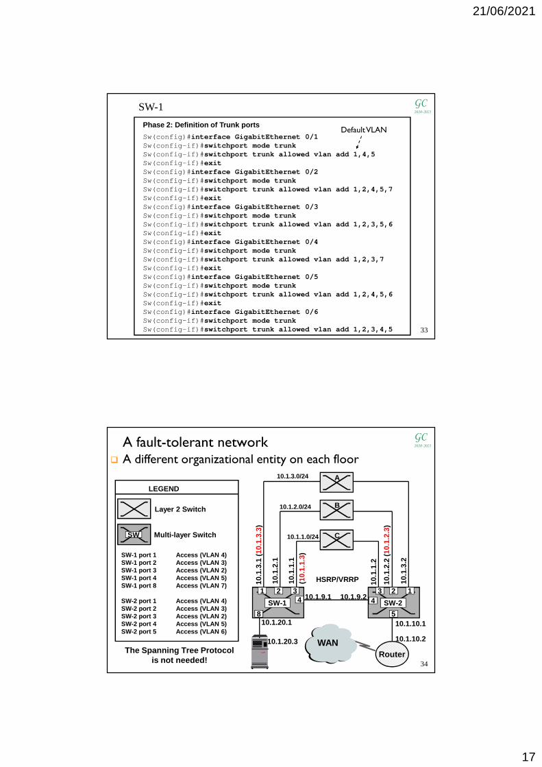
GC2020-2021A fault-tolerant network
10.1.9.1 10.1.9.2
Router
10.1.10.1
10.1.10.2
10.1
.1.1
(10.
1.1.
3)
10.1
.1.2
10.1
.2.1
10.1
.2.2
(10.
1.2.
3)
10.1
.3.1
(10.
1.3.
3)
10.1
.3.2
HSRP/VRRP
SW-1 SW-2
SW
Layer 2 Switch
Multi-layer Switch
LEGEND
1 2 34
3 2 14
5
SW-1 port 1 Access (VLAN 4)SW-1 port 2 Access (VLAN 3)SW-1 port 3 Access (VLAN 2)SW-1 port 4 Access (VLAN 5)SW-1 port 8 Access (VLAN 7)
SW-2 port 1 Access (VLAN 4)SW-2 port 2 Access (VLAN 3)SW-2 port 3 Access (VLAN 2)SW-2 port 4 Access (VLAN 5)SW-2 port 5 Access (VLAN 6)
810.1.20.1
A
B
C
The Spanning Tree Protocolis not needed!
WAN10.1.20.3
� A different organizational entity on each floor10.1.3.0/24
10.1.2.0/24
10.1.1.0/24
34

21/06/2021
18
GC2020-2021
RouterRouter 10.1.9.1 10.1.9.2
RouterWAN
10.1.10.1
10.1.10.2
10.1
.1.1
(10.
1.1.
3)
10.1
.1.2
10.1
.2.1
10.1
.2.2
(10.
1.2.
3)
10.1
.3.1
(10.
1.3.
3)
10.1
.3.2
HSRP/VRRP
1 2 34
3 2 14
5810.1.20.1
A
B
C
Logical view of the network in the previous slide
10.1.20.3
35
GC2020-2021SW-1(config)#interface vlan 2
SW-1(config-if)#ip address 10.1.1.1 255.255.255.0SW-1(config-if)#standby 8 preemptSW-1(config-if)#standby 8 priority 105SW-1(config-if)#standby 8 ip 10.1.1.3SW-1(config-if)#no shutdownSW-1(config-if)#exitSW-1(config)#interface vlan 3SW-1(config-if)#ip address 10.1.2.1 255.255.255.0SW-1(config-if)#standby 9 preemptSW-1(config-if)#standby 9 ip 10.1.2.3SW-1(config-if)#no shutdownSW-1(config-if)#exitSW-1(config)#interface vlan 4SW-1(config-if)#ip address 10.1.3.1 255.255.255.0SW-1(config-if)#standby 10 preemptSW-1(config-if)#standby 10 priority 105SW-1(config-if)#standby 10 ip 10.1.3.3SW-1(config-if)#no shutdownSW-1(config-if)#exitSW-1(config)#interface vlan 5SW-1(config-if)#ip address 10.1.9.1 255.255.255.252SW-1(config-if)#no shutdownSW-1(config-if)#exitSW-1(config)#interface vlan 7SW-1(config-if)#ip address 10.1.20.1 255.255.255.252
SW-1: IP address assignment and HSRP configuration
Candidate to become the Active router
Candidate to become the Active router
Candidate to become the Standby router
36

21/06/2021
19
GC2020-2021SW-2(config)#interface vlan 2
SW-2(config-if)#ip address 10.1.1.2 255.255.255.0SW-2(config-if)#standby 8 preemptSW-2(config-if)#standby 8 ip 10.1.1.3SW-2(config-if)#no shutdownSW-2(config-if)#exitSW-2(config)#interface vlan 3SW-2(config-if)#ip address 10.1.2.2 255.255.255.0SW-2(config-if)#standby 9 preemptSW-2(config-if)#standby 9 ip 10.1.2.3SW-2(config-if)#standby 9 priority 105SW-2(config-if)#no shutdownSW-2(config-if)#exitSW-2(config)#interface vlan 4SW-2(config-if)#ip address 10.1.3.2 255.255.255.0SW-2(config-if)#standby 10 preemptSW-2(config-if)#standby 10 ip 10.1.3.3SW-2(config-if)#no shutdownSW-2(config-if)#exitSW-2(config)#interface vlan 5SW-2(config-if)#ip address 10.1.9.2 255.255.255.252SW-2(config-if)#no shutdownSW-2(config-if)#exitSW-2(config)#interface vlan 6SW-2(config-if)#ip address 10.1.10.1 255.255.255.252
SW-2: IP address assignment and HSRP configuration
Candidate to become the Active router
Candidate to become the Standby router
Candidate to become the Standby router
37
GC2020-2021
A fault-tolerant network
Router
WAN
10.1.10.1
10.1.10.2
Spanning Tree Protocol
HSRP/ VRRP
SW-1 SW-2
1 2 34
3 2 14
5810.1.20.1
A
B
C
B.P
245
76
B.P
286
72
6 6
Trun
k
Trun
k
Trun
k
Trun
k
Trun
k
Trun
k
TrunkTrunk
VLANs 2,3,4span switches A,B,C
10.1.20.3
� VLANs span multiple switches on different floors
Layer 2 Switch
Multi-layer Switch
LEGEND
SW-1 ports 1,2,3,4,6 TrunkSW-1 port 8 Access (VLAN7)
SW-2 ports 1,2,3,4,6 TrunkSW-2 port 5 Access (VLAN6)
SW-1 VLAN 2 IP addr 10.1.1.1 ( 10.1.1.3)SW-1 VLAN 3 IP addr 10.1.2.1 ( 10.1.2.3)SW-1 VLAN 4 IP addr 10.1.3.1 ( 10.1.3.3)SW-1 VLAN 7 IP addr 10.1.20.1
SW-2 VLAN 2 IP addr 10.1.1.2SW-2 VLAN 3 IP addr 10.1.2.2SW-2 VLAN 4 IP addr 10.1.3.2SW-2 VLAN 6 IP addr 10.1.10.1
SW
c
Root port
Designated port
Blocking port
HSRP/VRRP
38

21/06/2021
20
GC2020-2021
Router
WAN 10.1.10.2
Spanning Tree Protocol
HSRP/ VRRP
1 2 34
3 2 1
4
5810.1.20.1
A
B
C
Router 10.1.3.1
10.1.2.110.1.1.1
10.1.10.1
Router10.1.3.2
10.1.2.2
10.1.1.2
6 6
Trun
k
Trun
k
Trun
k
Trun
k
Trun
k
Trun
k
Trunk
Trunk
c
Legend
Root port
Designated port
Blocking port
Logical view of the network in the previous slide
10.1.20.3
39
GC2020-2021
Router
WAN
10.1.10.2
10.1.20.1
Router(SW-1)
10.1.3.1
10.1.2.1
10.1.1.1
10.1.10.1
Router(SW-2)
10.1.3.2
10.1.2.2
10.1.1.2
VLAN 3
VLAN 4
VLAN 210.1.1.0/24
10.1.2.0/24
10.1.3.0/24
Logical view at the IP level
10.1.20.3
40

21/06/2021
21
GC2020-2021
SW-1(config)#interface vlan 2SW-1(config-if)#ip address 10.1.1.1 255.255.255.0SW-1(config-if)#standby 8 preemptSW-1(config-if)#standby 8 priority 105SW-1(config-if)#standby 8 ip 10.1.1.3SW-1(config-if)#no shutdownSW-1(config-if)#exitSW-1(config)#interface vlan 3SW-1(config-if)#ip address 10.1.2.1 255.255.255.0SW-1(config-if)#standby 9 preemptSW-1(config-if)#standby 9 priority 105SW-1(config-if)#standby 9 ip 10.1.2.3SW-1(config-if)#no shutdownSW-1(config-if)#exitSW-1(config)#interface vlan 4SW-1(config-if)#ip address 10.1.3.1 255.255.255.0SW-1(config-if)#standby 10 preemptSW-1(config-if)#standby 10 priority 105SW-1(config-if)#standby 10 ip 10.1.3.3SW-1(config-if)#no shutdownSW-1(config-if)#exitSW-1(config)#interface vlan 7SW-1(config-if)#ip address 10.1.20.1 255.255.255.252SW-1(config-if)#no shutdownSW-1(config-if)#exit
Candidate to be the Active router
Candidate to be the Active router
Candidate to be the Active router
SW-1: IP address assignment and HSRP configuration
41
GC2020-2021
SW-2(config)#interface vlan 2SW-2(config-if)#ip address 10.1.1.2 255.255.255.0SW-2(config-if)#standby 8 preemptSW-2(config-if)#standby 8 ip 10.1.1.3SW-2(config-if)#no shutdownSW-2(config-if)#exitSW-2(config)#interface vlan 3SW-2(config-if)#ip address 10.1.2.2 255.255.255.0SW-2(config-if)#standby 9 preemptSW-2(config-if)#standby 9 ip 10.1.2.3SW-2(config-if)#no shutdownSW-2(config-if)#exitSW-2(config)#interface vlan 4SW-2(config-if)#ip address 10.1.3.2 255.255.255.0SW-2(config-if)#standby 10 preemptSW-2(config-if)#standby 10 ip 10.1.3.3SW-2(config-if)#no shutdownSW-2(config-if)#exitSW-2(config)#interface vlan 6SW-2(config-if)#ip address 10.1.10.1 255.255.255.252SW-2(config-if)#no shutdownSW-2(config-if)#exit
SW-2: Assegnazione indirizzi IP e configurazione HS RP
Candidate to be the Standby router
Candidate to be the Standby router
Candidate to be the Standby router
42

21/06/2021
22
GC2020-2021Hierarchical network design
� The capacity, features and functionality of a specific device are optimized for its position in the network and the role it plays
� Costs are minimized
� It allows to design a modular topology
� Changes are facilitated because they impact a small number of systems
� The modular design makes the network easy to scale, understand and troubleshoot by promoting deterministic traffic patterns
� It reduces the number of CPU adjacencies
� When network devices communicate with many other devices, the workload of the CPUs on the devices can be burdensome
• In a large flat switched network broadcast packets are burdensome
• Routers process numerous route advertisements
� Classic three-layer model: core, distribution, access
� In small and medium-sized organizations, the core and distribution layers can be combined
43
GC2020-2021Hierarchical network design (cont.)
� An example of a flat network design
� An example of a hierarchical network design
Multilayer switch
L2 switch
44

21/06/2021
23
GC2020-2021
High Availability: downtime
High Availability
Very high Availability
Ultra high Availability
45
GC2020-2021
High Availability Campus Network Design
� Hierarchical campus network design
Source: Campus Network for High Availability Design Guide (Cisco Systems)
multilayerswitch
Firewall
L2switch
Router
Building BuildingBuilding
MAN/WAN
46

21/06/2021
24
GC2020-2021Core layer
� The core serves as the backbone for the network and connects distribution layer devices
� The core needs to be fast and extremely resilient because every building block depends on it for connectivity
� In the core a “less is more” approach should be taken
� A minimal configuration in the core reduces configuration complexity limiting the possibility for operational errors
47
GC2020-2021
Core layer (cont.)� Design the core layer as a high-speed, Layer 3 (L3) switching
environment
� Use redundant point-to-point L3 interconnections in the core building triangles, not squares
� Topologies with redundant equal-cost paths are the most deterministic and optimized for routing convergence, measured in milliseconds
� With topologies that rely on indirect notification and timer-based detection, convergence is non-deterministic and measured in seconds
� Most implementations of Internet routing protocols support load sharing across parallel paths with equal cost
� Equal-Cost MultiPath (ECMP) routing
� Fast, deterministic convergence in the event of a link or node failure
• Failover depends primarily on hardware link failure detection
• routing table with multiple entries for the destination 192.168.25.0/24
48

21/06/2021
25
GC2020-2021Distribution layer
� It aggregates switches from the access layer
� Typically deployed by a pair of multi-layer switches, that operate at layer-3 and, in case VLANs span multiple access switches, also as layer-2 switches
� Load sharing and Quality of Service (QoS) are key considerations at this layer
49
GC2020-2021Distribution layer (cont.)
� High availability in the distribution layer is provided through dual equal-cost paths from the distribution layer to the core and from the access layer to the distribution layer
� The distribution layer provides default gateway redundancy using a first-hop redundancy protocol (e.g., HSRP, VRRP, GLBP)
50

21/06/2021
26
GC2020-2021Access layer
� The first point of entry into the network for edge devices, such as hosts, IP phones, wireless access points
� The switches in the access layer are connected to two separate distribution layer switches for redundancy
� If there are no L2 loops, all uplinks can actively carry traffic
link aggregation
51
GC2020-2021Access layer (cont.)
� Key features:
� High availability (HA) supported by many hardware and software attributes
• Component redundancy using redundant supervisor engines, redundant power supplies and redundant fans
• Default gateway redundancy using dual connections to redundant distribution layer switches that use GLBP, HSRP or VRRP
• Prioritization of mission-critical network traffic using QoS
• Security services against unauthorized access to the network (e.g., IEEE 802.1x Access Control, MAC filters, DHCP snooping)
• Efficient network and bandwidth management using software features such as IGMP snooping
� Power Over Ethernet (PoE, PoE+, PoE++) for IP telephony, IP cameras, and for wireless access points
52

21/06/2021
27
GC2020-2021
Some “Best Practices”
53
GC2020-2021Network and In-the-Box Redundancy
� The hierarchical network model consists of � two core nodes with sufficient
bandwidth and switching capacity to service the entire network in the event of a failure of one of the nodes
� a distribution layer engineered with sufficient bandwidth and switching capacity so that the complete failure of one of the distribution nodes does not impact the performance of the network
� Network devices can provide high-availability by “in-the-box”redundancy, that involves doubling key components, such as the power supply, the fans, the supervisor engine.
� However, adding redundant supervisors to redundant core and distribution layers can increase the convergence time in the event of a supervisor failure (network outage of 1-3 seconds)� Instead, the network above converges in 100-200milliseconds for routing
protocols
Building BuildingBuilding
MAN/WAN
54

21/06/2021
28
GC2020-2021
Network and In-the-Box Redundancy (cont.)� So, campus topologies with redundant network paths can
converge faster than topologies that depend on redundant supervisors for convergence
� In-the-box redundancy provides the most benefit in environments where single points of failure exist
� The access layer of the network is typically a single point of failure� It is not typical for hosts to be dual connected to access layer
switches (except in the data center)� Then, the access layer is candidate for in-the-box redundancy
55
GC2020-2021
Core
Distribution
Access
Build triangles NOT squares� Squares
� Link failures require routing protocol convergence, which may vary since the route is non-deterministic.
� The result of this deployment is dropped sessions and/or lost packets, delivering suboptimal performance.
� Triangles� Any link failure results in a fast failover time since the route is deterministic.
A path is (simply) marked as unusable and all traffic is rerouted to the alternate equal-cost path (ECMP).
� The result is optimal performance with minimal packet loss.
56

21/06/2021
29
GC2020-2021
10.1.1.0/24 10.1.2.0/24
Link between the distribution nodes� Distribution layer designed as a L3 switching environment
� A L3 link is required between the distribution nodes
� The distribution node that loses connectivity to a given VLAN or subnet can reroute traffic across the distribution-to-distribution link
Layer 3
57
GC2020-2021Link between distribution nodes (cont.)
� In a design where VLANs are configured and span multiple access layer switches, the distribution nodes must be linked by an L2connection
� otherwise, multiple convergence events can occur for a single failure and undesirable traffic paths are taken after the spanning tree protocol converges
VLAN 2 VLAN 2
switch A switch B
Hellos
Core
Legend
Root port
Designated port
Blocking port
58

21/06/2021
30
GC2020-2021Link between distribution nodes (cont.)
� In case of a failure of the link from the access switch-A to the STP Root and HSRP Active multi-layer switch, the standby HSRP peer takes over as the default router
� Eventually, Access switch-B removes blocking on the link to the standby HSRP peer (with standard STP, this can take as long as 50 seconds)
� When STP/RSTP converges, the distribution nodes re-establish their HSRP relationships and the primary HSRP peer preempts
� yet another convergence event
59
GC2020-2021Link between distribution nodes (cont.)
� The unexpected side effect is that the Access switch-A traffic goes through the Access switch-B to reach its default gateway
VLAN 2 VLAN 2
switch A switch B
Hellos
Core
Legend
Root port
Designated port
Blocking port
60

21/06/2021
31
GC2020-2021Link between distribution nodes (cont.)
� Best Practice Topology for Spanning VLANs Across Access Layer Switches: a L2 link between the distribution multilayer switches
Core
VLAN 20 VLAN 30
VLAN 20VLAN 30
VLAN 20VLAN 30
VLAN 20VLAN 30
VLAN 20VLAN 30
Dual connected serversData Center
Legend
Root port
Designated port
Blocking port
61
GC2020-2021Daisy chaining dangers
� Black holes occur in the event of a link or device failure
� The standby HSRP peer can go active as it loses connectivity to its primary peer, forwarding traffic outbound for the devices that still have connectivity to it
� The primary HSRP peer remains active and also forwards outbound traffic for its half of the stack
Telecommunication Closet
62

21/06/2021
32
GC2020-2021Daisy Chaining dangers (cont.)
� A problem: return path traffic has a 50/50chance of arriving on a distribution switch that does not have physical connectivity to the half of the stack where the traffic is destined
� Traffic is dropped when it arrives on the wrong distribution switch
63
GC2020-2021Daisy Chaining dangers (cont.)
� provide alternate connectivity across the stack in the form of a loopback cable running from the top to the bottom of the stack
Telecommunication Closet
64

21/06/2021
33
GC2020-2021
Link Aggregation: IEEE 802.1AX� Link Aggregation Control Protocol (LACP)� It allows to aggregate the bandwidth of redundant links and
prevent a single point of failure� Without this logical grouping, if there are L2 loops, STP/RTSP
would place the redundant interface into blocking state to maintain a loop-free topology
LACP
65
GC2020-2021
Oversubscription and QoS
� Typical campus networks are engineered with oversubscription
� The rule-of-thumb recommendation for oversubscription is 20:1 ratio for access ports on the access-to-distribution uplink, 4:1 ratio for the distribution-to-core links, 1:1 ratio in the data center
66

21/06/2021
34
GC2020-2021
Oversubscription and QoS (cont.)� Using these oversubscription ratios, congestion on the uplinks
occurs by design
� When congestion occurs, QoS is required to protect important traffic such as mission-critical data applications, voice, and video
� Additionally, you can use QoS to reduce the priority of unwanted traffic (Scavenger-traffic class)
67
GC2020-2021References:
� Baldi, Nicoletti, SWITCHED LAN, McGraw-Hill
� Campus Network for High Availability Design Guide (Cisco Systems)
68

21/06/2021
35
GC2020-2021
An example of a high availability academic network design
69
GC2020-2021
Faculty of Engineering
Faculty of Science
Faculty of Law
Administration Office Internet
Scenario
70

21/06/2021
36
GC2020-2021
DMZ
MPLSMAN
Data Center
Internet
CAMPUS 3 CAMPUS 2
CAMPUS 1
CE router
CE router CE router
General architecture
� Simplified architecture (the redundancy is not shown)
71
GC2020-2021
INTERNET(GARR)
VPNCONCENTRATOR
Core
Access
Distribution
DMZData Center
Building 1 Building 2 Building 3 Building 4
Internet Edge
MPLS MAN
MANEdge
CErouter
Other campuses
Logical architecture of the main campus
72

21/06/2021
37
GC2020-2021
INTERNET(GARR)
STREAMINGDNS MAIL WEB
NIDS
Data Center
APPLICATIONDHCP
RADIUS
SIPGATEWAY
NIDS
DMZ
Other buildings in the
campus
PSTN
VPNCONCENTRATOR
MAN Edge
Internet Edge
MANAGEMENT
MAIL FILTER
DB
MPLS MAN
CErouter
Other campuses
Logical architecture in the building 1 of the campus 1
73
GC2020-2021
INTERNET(GARR)
Data Center
MANEdge
Building 1
Building 2 Building 3 Building 4
WLAN Controller
AP
Internet Edge
AP AP
MPLS MAN
Other campuses
Wireless network architecture
74

21/06/2021
38
GC2020-2021
75
Data center evolution
GC2020-2021
76
Traditional three-tier data center (DC) design
� Servers are segmented into pods and virtualized into sets of virtual machines (VMs)
� VLANs are configured within each pod (multitenancy), and virtual machines (VMs) can move freely within the pod without the need to change IP address and default gateway configurations
� STP is used in the L2 part of the network, so that parallel forwarding path cannot be used

21/06/2021
39
GC2020-2021
77
DC design with extended layer 2 domain
� With layer 2 segments extended across all the pods, the DC administrator can create a more flexible resource pool that can be reallocated based on needs (elasticity of cloud computing)
� Virtual link-aggregation techniques allow to overcome the limitations of STP, providing active-active uplinks
vPC (virtual-Port-Channel) can provide only two activeparallel links
GC2020-2021
78
Limitations of a three-tier DC architecture
� With virtualized servers, applications are increasingly deployed in a distributed fashion, which leads to large and ever increasing “machine-to-machine” traffic (east-west traffic)
� In a modern DC this type of traffic is several orders of magnitude larger than what goes out to the Internet
� The job of a DC network (DCN) is to interconnect servers in a way that maximizes the bandwidth between any two servers (bisection bandwidth), while minimizing the latency between them
� In a three-tier DCN
� bisection bandwidth becomes a bottleneck
� server-to-server latency depends on the traffic path used

21/06/2021
40
GC2020-2021
79
Spine and leaf topology
� A Clos network-based spine-and-leaf architecture delivers high-bandwidth, low and predictable latency, nonblocking server-to-server connectivity
� Expanding capacity is straightforward: an additional spine switch can be added
� If device port capacity becomes a concern, a new leaf switch can be added
Fully connected
GC2020-2021
80
VXLAN tunneling technology (RFC 7348)� VXLAN (Virtual eXtensible LAN) is an extension to VLAN and has
become the mainstream technology for constructing DC networks
� VXLAN can meet the requirements of dynamic VM migration and multi-tenancy in DC networks
� VXLAN encapsulates layer-2Ethernet frames into UDP packets and transports the encapsulated packets over an IP network using the normal IP routing and forwarding mechanisms (thus, VXLAN builds a logical L2 overlay network over a L3 underlay network)

21/06/2021
41
GC2020-2021
Layer 2 virtualswitch
DCN
81
VXLAN tunneling technology (cont.)� VXLAN virtualizes the DC network into a large layer 2 virtual
switch, that isolates traffic between the VXLAN segments
� When a VM is migrated within the same VXLAN segment, its IP address does not need to be changed
� Each VXLAN segment is identified by a 24-bit VXLAN network identifier (VNI), that is similar to a VLAN ID
� A maximum of 16M VXLAN segments are supported (and so, 16M tenants)
GC2020-2021
82
VXLAN packet format� A VXLAN tunnel endpoint (VTEP) encapsulates the original
Ethernet frame
� The VNI is added to a VXLAN header
� Outer Src.IP is the IP address of the VTEP connected to the source VM
� Outer Dst. IP is the IP address of the VTEP connected to the destination VM

21/06/2021
42
GC2020-2021
83
VXLAN packet format (cont.)
� In figure, a tunnel is established between two top of rack (TOR) switches
GC2020-2021
84
MP-BGP-EVPN (RFC 7432)� MP-BGP-EVPN: Multiprotocol BGP Ethernet VPN
� RFC 7348did not define any control plane for VXLAN
� VXLAN tunnels are manually configured
� host addresses are learned through multicast-based traffic flooding (each VNI is mapped to an IP multicast group)
� Ingress replication feature (introduced for organizations that do not want enable multicast in their data centers or WANs): the VTEP uses a list of IP addresses of other VTEPs to send broadcast, unknown, and multicast traffic (BUM traffic)
� RFC 7432 specifies MP-BGP-EVPN as the control plane of VXLAN
� VTEPs can be automatically discovered and VXLAN tunnels can be automatically established
� Each VTEP performs local learning to obtain MAC addresses (traditional MAC address learning) and IP address information from its locally attached hosts
� The VTEP then distributes this information to other VTEPs through MP-BGP-EVPN
� Flooding traffic is reduced on the network

21/06/2021
43
GC2020-2021
85
� When traffic need to be routed, the Layer 3 gateway function needs to be enabled on some VTEPs
� The common designs used are internal and external routing on the spine layer, and internal and external routing on the leaf layer
� Both designs provide centralized routing: the internal and external routing functions are centralized on specific switches of the DCN
� In case MP-BGP-EVPN is used, internal routing can be distributed: any VTEP in a VNI can be the distributed anycast gateway for hosts in its IP subnet, by supporting the same virtual gateway IP address and the virtual gateway MAC address.
Layer 3 routing function with VXLAN
GC2020-2021Reference white papers for the topic “data center
evolution”:
� “Cisco Data Center Spine-and-Leaf architecture: Design Overview”, https://www.cisco.com/c/en/us/products/collateral/switches/nexus-7000-series-switches/white-paper-c11-737022.html
� “What is VXLAN” , HUAWEI Technologies, https://support.huawei.com/enterprise/it/doc/EDOC1100086966
� “ EVPN-VXLAN CAMPUS FABRICS ”, JUNIPER Networks
86

21/06/2021
44
GC2020-2021
A bit of future
GC2020-2021
� The explosion of mobile devices, the server virtualization and the advent of cloud services are driving the networking industry to re-examine network architectures
� Modern traffic pattern are incredibly dynamic and, therefore, unpredictable
� To implement a network-wide policy (access, security, QoS, .. ), IT operators may have to configure thousands of devices
• Policies may be inconsistent
� Due to complexity, today’s networks are relatively static as many IT operators seek to minimize the risk of service disruption
� Software Defined Networking (SDN) is an emerging network architecture where network’s control plane (brain) is decoupled from forwarding plane (muscle)
Software Defined Networking
88

21/06/2021
45
GC2020-2021Software Defined Networking (cont.)
� SDN provides for the implementation of control plane to be open (and standard-based)
� The Open Networking Foundation (ONF) is the groupthat is most associated with the standardization and development of SDN
� Some important SDN use cases:
� Dynamic QoS
� Traffic engineering
� Role based access
� Load balancing services
� Security services
89
GC2020-2021Traditional approach: per-router control plane
RoutingAlgorithm
dataplane
controlplane
1
2
0111
values in arriving packet header
3
� Individual routing algorithm components in each and every router interact with each other in control plane to compute forwarding tables
90

21/06/2021
46
GC2020-2021Control plane and data plane separation
� A logically centralized software program (Remote Controller) controls the behaviour of an entire network
� IT operators can program -and reprogram- the network in real time to meet specific business and user needs as they arise
dataplane
controlplane
Remote Controller
CA
CA CA CA CA
routingaccess control
loadbalance
… control plane functions external to data-plane of packet switches
Packet switch
Controller Agent
local flow table
headers counters actions
91
GC2020-2021The Openflow protocol
� The Controller interacts with control agents (CAs) in packet switches to compute and distribute forwarding tables (called flow tables in SDN)
� Examples of open source SDN controllers: Opendaylight, ONOS
� OpenFlow structures communication between the Controller and the CAs
� The concept of flow is used to identify network traffic based on match rules programmed by the SDN control software
� The match-action paradigm
� “Match” can be done on multiple header fields (up to 41) associated to different protocol layers
� “Action” allows to define how traffic should be forwarded by the packet switch 92

21/06/2021
47
GC2020-2021OpenFlow: Flow Table Entries
Ingress
PortMAC
src
MAC
dst
Eth
typeVLAN
ID
IP
Src
IP
Dst
IP
Prot
TCP/UDP
Src port
Match rule Action Stats
1. Forward packet to port(s)
2. Encapsulate and forward to controller
3. Drop packet
4. Modify Fields
Packet + byte counters
Link layer Network layer Transport layer
VLAN
Pri
IP
TOS
TCP/UDP
Dst port
93
GC2020-2021
IP Src = 10.3.*.*IP Dst = 10.2.*.*
forward(3)
match action
ingress port = 2IP Dst = 10.2.0.3ingress port = 2IP Dst = 10.2.0.4
forward(3)
match action
forward(4)
ingress port = 1IP Src = 10.3.*.*IP Dst = 10.2.*.*
forward(4)
match action
OpenFlow example
Host h110.1.0.1
Host h210.1.0.2
Host h410.2.0.4
Host h310.2.0.3
Host h510.3.0.5
s1 s2
s31
2
3 4
1
2
34
1
2
3
4
Host h610.3.0.6
Example: IP datagrams from hosts h5 and h6 should be sent to h3 or h4, via s1 and from there to s2
94
controller

21/06/2021
48
GC2020-2021References for the topic “SDN”:
� J. Kurose e K.W. Ross, “Computer Networking. A Top-Down Approach”, seventh edition, Pearson
95
GC2020-2021Intent-based networking
� Future networks will operate as a system withincreasing levels of autonomy
� The key to achieve this more autonomous state will beartificial intelligence
� An Intent-based network (IBN) will be able to take a business requirement communicated in natural language
� A human operator defines “what” is expected
� The IBN will automatically translate business requirements into network requirements and, then, compute a solution meeting the requirements
� So, an IBN will be able to align the network continuously and dynamically to changing business needs
96

21/06/2021
49
GC2020-2021Learning outcomes
After the course the student should
� understand the main issues regarding the operation of a modern computer network and how they could be addressed in order to ensure appropriate delivery of the application services
� know the technologies to be considered in designing a modern computer network and, particularly, understand how they address the aforementioned issues
� know what techniques can be adopted to model and analytically evaluate performance, reliability and availability of network systems
97