Embed Size (px)
Citation preview
On The Design of A DynamicallyReconfigurable Function-Unit for Error
Thilo Pionteck∗1, Thomas Stiefmeier∗2, Thorsten Staake∗3,4
1 University of Lubeck, Institute of Computer Engineering, 23538 Lubeck, Germany,[email protected]
2 ETH Zurich, Wearable Computing Lab, CH-8092 Zurich, Switzerland,[email protected]
3 University of St.Gallen, Institute of Technology Management, CH-9000 St. Gallen,Switzerland, [email protected]
4 Darmstadt University of Technology, Institute of Microelectronic Systems, 64283Darmstadt, Germany, [email protected]
Abstract. This paper presents the design of a function-specific dynam-ically reconfigurable architecture for error detection and error correc-tion. The function-unit is integrated in a pipelined 32 bit RISC processorand provides full hardware support for encoding and decoding of Reed-Solomon Codes with different code lengths as well as error detectionmethods like bit-parallel Cyclic Redundancy Check codes computation.The architecture is designed and optimized for the usage in the mediumaccess control layer of mobile wireless communication systems and pro-vides simultaneously hardware support for control-flow and data-floworiented tasks.
1 Introduction
For wireless communication systems the capability of receivers to detect andcorrect transmission errors is of great importance. While error detection meth-ods require bandwidth expensive retransmissions, error correction methods leadto a better bandwidth efficiency. Albeit this advantage, error correction codesare not often used for mobile wireless communication systems due to their de-coding complexity. Software solutions would require powerful processors, lead-ing to an unacceptable power consumption for battery powered mobile de-vices. Hardware solutions are often optimized for throughput, yet are inflexibleand do not consider the requirements of mobile terminals. For mobile wirelesscommunication terminals, the critical design parameter is not throughput butarea efficiency and power consumption. Though works exist on area-efficientor (re)configurable Reed-Solomon decoders (e.g. [2, 15]), the potentials of dy-namically reconfigurable approaches concerning hardware savings are often not
∗ The authors performed this work while at Darmstadt University of Technology
Pionteck, T., Stiefmeier, T., Staake, T., Glesner, M., 2007, in IFIP International Federation for Information Processing, Volume 240, VLSI-SoC: From Systems to Silicon, eds. Reis, R., Osseiran, A., Pfleiderer, H-J., (Boston: Springer), pp. 283–297.
Detection and Correction
and Manfred Glesner
taken into consideration. However, temporal reuse of hardware within the de-coding offers the best potential to achieve an area-efficient design. The inherenthardware overhead of reconfigurable solutions can be avoided by restrictingthe reconfiguration capabilities to one application area, resulting in a function-specific reconfigurable device.
In the following the design of a dynamically reconfigurable function-unit(RFU) supporting Cyclic Redundancy Checks (CRC) and Reed-Solomon Codeswith different code lengths is presented. The RFU is optimized regarding areaand fulfills the performance requirements for actual wireless communicationstandards. In combination with a processor, the RFU allows the design of aflexible solution for the MAC (M edium Access Control) layer of WLANs. Re-configuration can be done during runtime, allowing the processor to utilize allarithmetic components and memory elements of the RFU for additional taskslike multiplication in the Galois Field required for encryption standards likeAES (Advanced Encryption S tandard) [1].
The outline of the contribution is as follows: Section 2 provides a shortreview of error detection and error correction codes. In Section 3, a referencedesign for a Reed-Solomon decoder is presented. This decoder was used as astarting point for the design of the function-specific reconfigurable architectureintroduced in Section 4. Section 5 deals with the system integration of the RFU,and Section 6 presents performance and synthesis results. Finally, conclusionsare given in Section 7.
2 Error Detection and Correction Codes
Error detection codes have efficiently been employed in many communicationprotocols. They enable the receiver to detect whether a received code word iscorrupted or not. As the receiver does not have the information required forcorrecting the error, a retransmission of the corrupted data has to be initiated.Error correction codes extend the redundant part of the message with informa-tion so that errors up to a certain degree of corruption can be corrected. Thusthe retransmission probability can be reduced considerably by using forwarderror correction (FEC).
2.1 Cyclic Redundancy Check
Cyclic Redundancy Check codes are a powerful subclass of error detection codesand are well-suited for detecting burst errors. The basic idea is to expand a k-bit message, described by a polynomial u(x) with coefficients in {0,1}, withthe remainder Rg(x) of the division of xn−k · u(x) by a m = (n − k)th-ordergenerator polynomial g(x) using modulo-2 arithmetic, resulting in an n-bit codeword v(x). If v(x) is affected by an error polynomial e(x), a receiver can checkthe integrity of the received data ve(x) = v(x)+ e(x) by dividing ve(x) by g(x).A non-zero remainder r(x) indicates the presence of errors [14].
284 Pionteck et al.
There exist two common approaches to perform CRC computation, a bit-serial and a bit-parallel one. The serial approach uses a linear feedback shiftregister (LFSR) based on the generator polynomial g(x). One bit is processedper cycle which results in low performance. The parallel CRC computationmethod is based on multiplications in Galois Fields. Here, a message u(x) isdivided into blocks of length m = n−k denoted by Wi(x). Using the congruenceproperties of modulo-2 operations and the fact that the degree of Wi(x) is lessthan m, the code word v(x) can be written as v(x) = WN−1 ⊗ βN−1 ⊕ . . . ⊕W0 ⊗ β0, where ⊗ and ⊕ denote the multiplication and addition over a GaloisField GF (2m), respectively. The coefficients βi depend only on the generatorpolynomial g(x) and can be computed in advance. A more detailed descriptioncan be found in [11].
2.2 Reed-Solomon Codes
Reed-Solomon (RS) Codes are a very common group of systematic linear blockcodes and are based on operations in Galois Fields. A RS(n,k) code word v(x)consists of n symbols of length m, divided into k message symbols and (n− k)parity symbols. Up to (n− k) symbol errors can be detected and t = (n− k)/2symbol errors can be corrected.
The binary representation of the original data is segmented into k symbolsof m bits. These symbols are interpreted as elements of a Galois Field GF (2m),constructed by a primitive polynomial p(x) of degree m. The resulting messagepolynomial u(x) is then multiplied by the polynomial xn−k and added to theremainder polynomial r(x) to form the code word polynomial v(x) = xn−k ·u(x) + r(x). The term r(x) is the remainder of the division of xn−k · u(x) by agenerator polynomial g(x) of degree n− k.
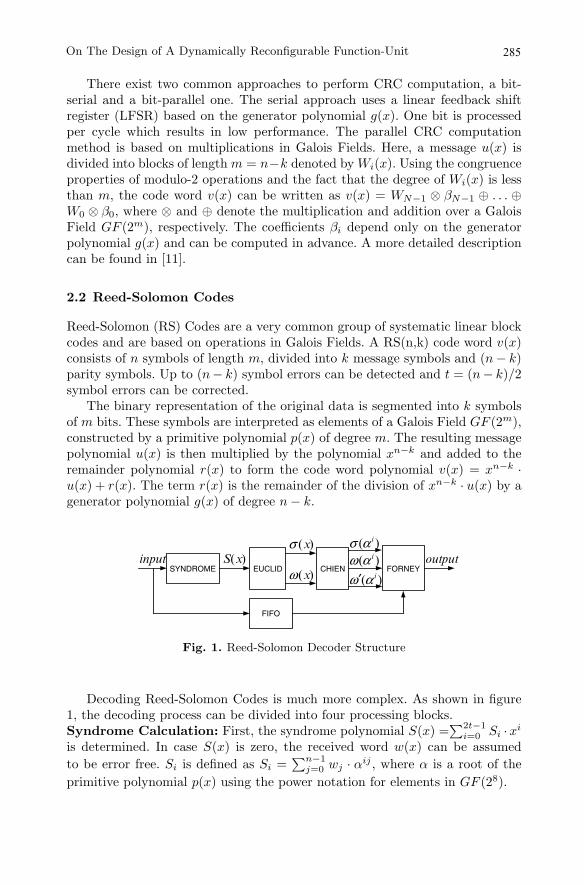
Fig. 1. Reed-Solomon Decoder Structure
Decoding Reed-Solomon Codes is much more complex. As shown in figure1, the decoding process can be divided into four processing blocks.Syndrome Calculation: First, the syndrome polynomial S(x) =
∑2t−1i=0 Si ·xi
is determined. In case S(x) is zero, the received word w(x) can be assumedto be error free. Si is defined as Si =
∑n−1j=0 wj · αij , where α is a root of the
primitive polynomial p(x) using the power notation for elements in GF (28).
285On The Design of A Dynamically Reconfigurable Function-Unit
���� �� �� �� �
����
)( iαω
)( iαω′
)( iασ)(xσ
)(xω
)(xSinput outputSYNDROME EUCLID CHIEN
FIFO
FORNEY
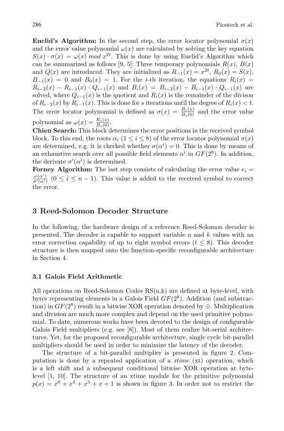
Euclid’s Algorithm: In the second step, the error locator polynomial σ(x)and the error value polynomial ω(x) are calculated by solving the key equationS(x) · σ(x) = ω(x) mod x2t. This is done by using Euclid’s Algorithm whichcan be summarized as follows [9, 5]: Three temporary polynomials R(x), B(x)and Q(x) are introduced. They are initialized as R−1(x) = x2t, R0(x) = S(x),B−1(x) = 0 and B0(x) = 1. For the i-th iteration, the equations Ri(x) =Ri−2(x) − Ri−1(x) · Qi−1(x) and Bi(x) = Bi−2(x) − Bi−1(x) · Qi−1(x) aresolved, where Qi−1(x) is the quotient and Ri(x) is the remainder of the divisonof Ri−2(x) by Ri−1(x). This is done for s iterations until the degree of Ri(x) < t.The error locator polynomial is defined as σ(x) = Bs(x)
Bs(0) and the error value
polynomial as ω(x) = Rs(x)Bs(0) .
Chien Search: This block determines the error positions in the received symbolblock. To this end, the roots αi (1 ≤ i ≤ 8) of the error locator polynomial σ(x)are determined, e.g. it is checked whether σ(αi) = 0. This is done by means ofan exhaustive search over all possible field elements αi in GF (28). In addition,the derivate σ′(αi) is determined.Forney Algorithm: The last step consists of calculating the error value ei =ω(αi)σ′(αi) (0 ≤ i ≤ n − 1). This value is added to the received symbol to correctthe error.
3 Reed-Solomon Decoder Structure
In the following, the hardware design of a reference Reed-Solomon decoder ispresented. The decoder is capable to support variable n and k values with anerror correction capability of up to eight symbol errors (t ≤ 8). This decoderstructure is then mapped onto the function-specific reconfigurable architecturein Section 4.
3.1 Galois Field Arithmetic
All operations on Reed-Solomon Codes RS(n,k) are defined at byte-level, withbytes representing elements in a Galois Field GF (28). Addition (and substrac-tion) in GF (28) result in a bitwise XOR operation denoted by ⊕. Multiplicationand division are much more complex and depend on the used primitive polyno-mial. To date, numerous works have been devoted to the design of configurableGalois Field multipliers (e.g. see [8]). Most of them realize bit-serial architec-tures. Yet, for the proposed reconfigurable architecture, single cycle bit-parallelmultipliers should be used in order to minimize the latency of the decoder.
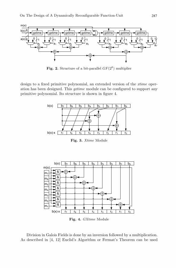
The structure of a bit-parallel multiplier is presented in figure 2. Com-putation is done by a repeated application of a xtime (xt) operation, whichis a left shift and a subsequent conditional bitwise XOR operation at byte-level [1, 10]. The structure of an xtime module for the primitive polynomialp(x) = x8 + x4 + x3 + x + 1 is shown in figure 3. In order not to restrict the
286 Pionteck et al.
gxtime8
08 1 0 1 0 01 1
b(x)
a(x)a0 a1 a2 a3
0 1 0 1 0 01 1a4 a5 a6 a7
m(x)
gxtime gxtime gxtime gxtime gxtime gxtime
Fig. 2. Structure of a bit-parallel GF (28) multiplier
design to a fixed primitive polynomial, an extended version of the xtime oper-ation has been designed. This gxtime module can be configured to support anyprimitive polynomial. Its structure is shown in figure 4.
���� �� �� �� ��� �����
� � � � � � ���� �
Fig. 3. Xtime Module
���� �� �� �� ��� �����
� � � � � � ���� �
�
�
�
�
�
�
�
��
�
��
��
��
��
��
����
Fig. 4. GXtime Module
Division in Galois Fields is done by an inversion followed by a multiplication.As described in [4, 12] Euclid’s Algorithm or Fermat’s Theorem can be used
287On The Design of A Dynamically Reconfigurable Function-Unit
for the inversion. In the reference architecture a third method based on look-up tables is used. Although this approach requires more chip area than othermethods, the look-up tables were chosen since they offer higher flexibility andhigher speed. In the subsequent reconfigurable architecture the look-up tablescan also be used for several other purposes.
3.2 Reed-Solomon Decoder Blocks
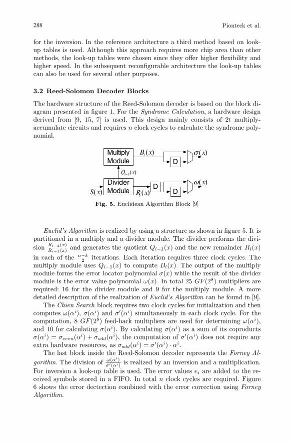
The hardware structure of the Reed-Solomon decoder is based on the block di-agram presented in figure 1. For the Syndrome Calculation, a hardware designderived from [9, 15, 7] is used. This design mainly consists of 2t multiply-accumulate circuits and requires n clock cycles to calculate the syndrome poly-nomial.
Fig. 5. Euclidean Algorithm Block [9]
Euclid’s Algorithm is realized by using a structure as shown in figure 5. It ispartitioned in a multiply and a divider module. The divider performs the divi-sion Ri−2(x)
Ri−1(x) and generates the quotient Qi−1(x) and the new remainder Ri(x)in each of the n−k
2 iterations. Each iteration requires three clock cycles. Themultiply module uses Qi−1(x) to compute Bi(x). The output of the multiplymodule forms the error locator polynomial σ(x) while the result of the dividermodule is the error value polynomial ω(x). In total 25 GF (28) multipliers arerequired: 16 for the divider module and 9 for the multiply module. A moredetailed description of the realization of Euclid’s Algorithm can be found in [9].
The Chien Search block requires two clock cycles for initialization and thencomputes ω(αi), σ(αi) and σ′(αi) simultaneously in each clock cycle. For thecomputation, 8 GF (28) feed-back multipliers are used for determining ω(αi),and 10 for calculating σ(αi). By calculating σ(αi) as a sum of its coproductsσ(αi) = σeven(αi) + σodd(αi), the computation of σ′(αi) does not require anyextra hardware resources, as σodd(αi) = σ′(αi) · αi.
The last block inside the Reed-Solomon decoder represents the Forney Al-gorithm. The division of ω(αi)
σ′(αi) is realized by an inversion and a multiplication.For inversion a look-up table is used. The error values ei are added to the re-ceived symbols stored in a FIFO. In total n clock cycles are required. Figure6 shows the error dectection combined with the error correction using ForneyAlgorithm.
288 Pionteck et al.
DividerModule
MultiplyModule
)(1 xQi−
DD)(xS
D)(xBi
)(xRi
)(xω
)(xσ
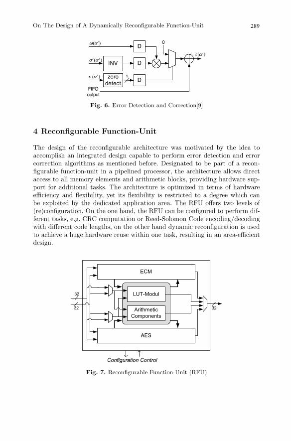
Fig. 6. Error Detection and Correction[9]
4 Reconfigurable Function-Unit
The design of the reconfigurable architecture was motivated by the idea toaccomplish an integrated design capable to perform error detection and errorcorrection algorithms as mentioned before. Designated to be part of a recon-figurable function-unit in a pipelined processor, the architecture allows directaccess to all memory elements and arithmetic blocks, providing hardware sup-port for additional tasks. The architecture is optimized in terms of hardwareefficiency and flexibility, yet its flexibility is restricted to a degree which canbe exploited by the dedicated application area. The RFU offers two levels of(re)configuration. On the one hand, the RFU can be configured to perform dif-ferent tasks, e.g. CRC computation or Reed-Solomon Code encoding/decodingwith different code lengths, on the other hand dynamic reconfiguration is usedto achieve a huge hardware reuse within one task, resulting in an area-efficientdesign.
���
�� �
� � � � � �
�� � � � � � � � �
� � � � � � � �
������������������
� �
� �� �
Fig. 7. Reconfigurable Function-Unit (RFU)
289On The Design of A Dynamically Reconfigurable Function-Unit
DINV
0
zerodetect
)( iαω
)(' iασ
)( iασ
FIFOoutput
1
)( ic α
D
D
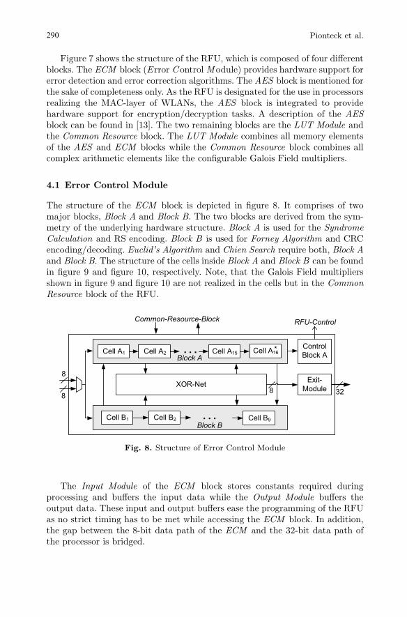
Figure 7 shows the structure of the RFU, which is composed of four differentblocks. The ECM block (E rror Control M odule) provides hardware support forerror detection and error correction algorithms. The AES block is mentioned forthe sake of completeness only. As the RFU is designated for the use in processorsrealizing the MAC-layer of WLANs, the AES block is integrated to providehardware support for encryption/decryption tasks. A description of the AESblock can be found in [13]. The two remaining blocks are the LUT Module andthe Common Resource block. The LUT Module combines all memory elementsof the AES and ECM blocks while the Common Resource block combines allcomplex arithmetic elements like the configurable Galois Field multipliers.
4.1 Error Control Module
The structure of the ECM block is depicted in figure 8. It comprises of twomajor blocks, Block A and Block B. The two blocks are derived from the sym-metry of the underlying hardware structure. Block A is used for the SyndromeCalculation and RS encoding. Block B is used for Forney Algorithm and CRCencoding/decoding. Euclid’s Algorithm and Chien Search require both, Block Aand Block B. The structure of the cells inside Block A and Block B can be foundin figure 9 and figure 10, respectively. Note, that the Galois Field multipliersshown in figure 9 and figure 10 are not realized in the cells but in the CommonResource block of the RFU.
�
�
� � � � � � � � � � � � � �
���
�������
���
�������
� � � � � � � � � � � � � � � � �
� � � � � �
� � � � � � � � � � � � � � � ��
� � � � � � �� � � � �����
� � � � � � �
� � � � � �
� � � � � � � � ��
� � � � �
� � � � � �� � �
Fig. 8. Structure of Error Control Module
The Input Module of the ECM block stores constants required duringprocessing and buffers the input data while the Output Module buffers theoutput data. These input and output buffers ease the programming of the RFUas no strict timing has to be met while accessing the ECM block. In addition,the gap between the 8-bit data path of the ECM and the 32-bit data path ofthe processor is bridged.
290 Pionteck et al.
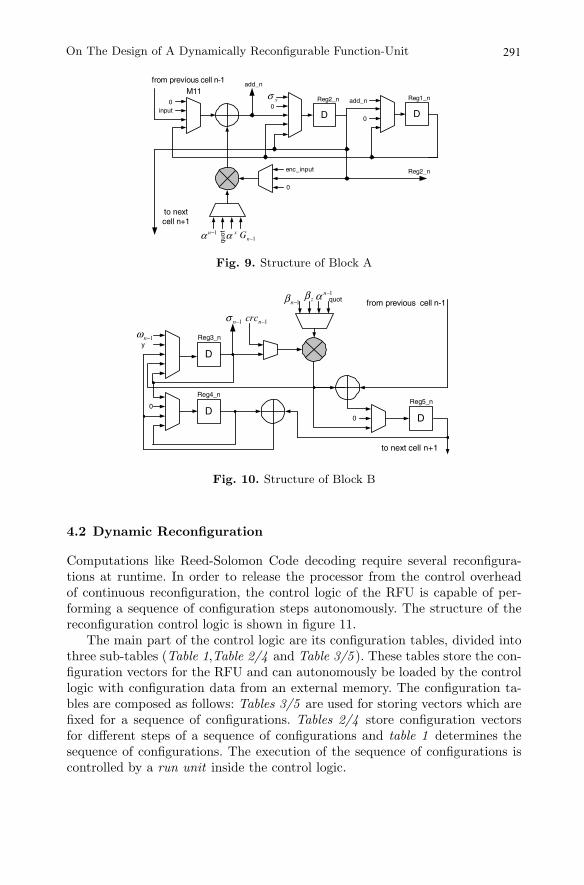
Fig. 9. Structure of Block A
Fig. 10. Structure of Block B
4.2 Dynamic Reconfiguration
Computations like Reed-Solomon Code decoding require several reconfigura-tions at runtime. In order to release the processor from the control overheadof continuous reconfiguration, the control logic of the RFU is capable of per-forming a sequence of configuration steps autonomously. The structure of thereconfiguration control logic is shown in figure 11.
The main part of the control logic are its configuration tables, divided intothree sub-tables (Table 1,Table 2/4 and Table 3/5 ). These tables store the con-figuration vectors for the RFU and can autonomously be loaded by the controllogic with configuration data from an external memory. The configuration ta-bles are composed as follows: Tables 3/5 are used for storing vectors which arefixed for a sequence of configurations. Tables 2/4 store configuration vectorsfor different steps of a sequence of configurations and table 1 determines thesequence of configurations. The execution of the sequence of configurations iscontrolled by a run unit inside the control logic.
291On The Design of A Dynamically Reconfigurable Function-Unit
input
Reg2_n
D D
Reg1_nReg2_n00
add_n
0
xσ
enc_input
0
1−nα
xα 1−nG
quot
M11add_n
to nextcell n+1
from previous cell n-1
D
DD
1−nβ zβ1−n
α quot
1−ncrc1−nσ
Reg3_n
Reg5_nReg4_n
0
y
0
to next cell n+1
from previous cell n-1
1−nω

selecttable
Configuration Tables
run unitAddr
prog. unitAddr
externReconfiguration
MemoryDataAddr
a
boutRFU
Table 3
instructionword control signal from RFU
Table 5
Table 2
Table 1
Table 4
Fig. 11. Reconfiguration Control Logic
In each clock cycle a new entry in configuration table 1 is selected by therun unit. In total 128 entries are provided. Processed configurations can beexchanged at runtime, enabling sequences of configurations with more than 128steps. One table entry of table 1 consists of eight bits. Three of these bits areeither passed directly to the RFU or are used by the run unit for realizing(un)conditional jumps and loops. The other five bits of table 1 are used as anaddress for table 2 or table 4, consisting of 32 x 32 bits each. Table 3 andtable 5 have a capacity of 32 bits each. Besides their usage for storing thefixed part of the configuration vector, they can also be used to provide the rununit with the number of iterations for repeated execution and with the offsetvalues for (un)conditional jumps. This subdivision of the configuration memoryallows to reduce the required size of configuration memory as not the completeconfiguration vector of 67 bits has to be stored for each step of the sequence. Thedivision also eases the reprogramming. Only one table combination table 2/3 ortable 4/5 can be active at runtime. The other combination can be reprogrammedwithout affecting the system.
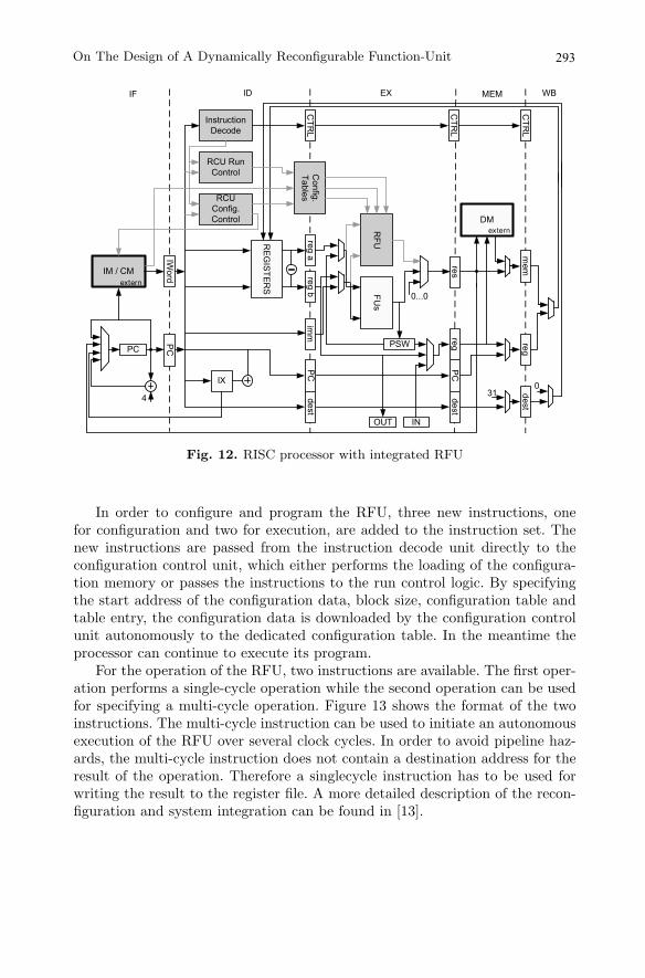
5 Processor Integration
The RFU was integrated into a 32 bit 5 stage pipelined RISC core, derived fromthe DLX architecture [3]. Figure 12 shows the simplified datapath of the RISCprocessor with the integrated RFU. All changes made to the original datapathare highlighted. The RFU is placed next to the other function-units and utilizesthe same datapaths to access the register files. The output of the RFU is non-registered. This constellation allows a full integration of the new function-unitin the pipeline structure of the processor. It also eases the integration into otherprocessor designs.
292 Pionteck et al.
IM / CM
PC
IWord
PC
REGISTER
S
RCU Config. Control
Config. Tables
RFU
FUs
INOUT
DM
PSWreg b
reg aPC
imm
dest
PCreg
destres
regmem
dest
IX
Instruction Decode
40
31
0...0extern
extern
IF WBMEMEXID
CTRL
RCU Run Control
CTRL
CTRL
Fig. 12. RISC processor with integrated RFU
In order to configure and program the RFU, three new instructions, onefor configuration and two for execution, are added to the instruction set. Thenew instructions are passed from the instruction decode unit directly to theconfiguration control unit, which either performs the loading of the configura-tion memory or passes the instructions to the run control logic. By specifyingthe start address of the configuration data, block size, configuration table andtable entry, the configuration data is downloaded by the configuration controlunit autonomously to the dedicated configuration table. In the meantime theprocessor can continue to execute its program.
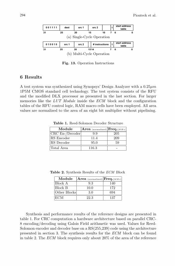
For the operation of the RFU, two instructions are available. The first oper-ation performs a single-cycle operation while the second operation can be usedfor specifying a multi-cycle operation. Figure 13 shows the format of the twoinstructions. The multi-cycle instruction can be used to initiate an autonomousexecution of the RFU over several clock cycles. In order to avoid pipeline haz-ards, the multi-cycle instruction does not contain a destination address for theresult of the operation. Therefore a singlecycle instruction has to be used forwriting the result to the register file. A more detailed description of the recon-figuration and system integration can be found in [13].
293On The Design of A Dynamically Reconfigurable Function-Unit
����������� ���� ���� ��� ���������������
��� �
�� ������ � ��
(a) Single-Cycle Operation
����������� ����� ����� �����������
�� ���������������
�� �������� � ��
(b) Multi-Cycle Operation
Fig. 13. Operation Instructions
6 Results
A test system was synthesized using Synopsys’ Design Analyzer with a 0.25µm1P5M CMOS standard cell technology. The test system consists of the RFUand the modified DLX processor as presented in the last section. For largermemories like the LUT Module inside the ECM block and the configurationtables of the RFU control logic, RAM macro cells have been employed. All areavalues are normalized to the area of an eight bit multiplier without pipelining.
Table 1. Reed-Solomon Decoder Structure
Module Area (normalized) Freq.[MHz]
CRC En-/Decoder 9.9 205
RS Encoder 11.4 209
RS Decoder 95.0 59
Total Area 116.3 -
Table 2. Synthesis Results of the ECM Block
Module Area (normalized) Freq.[MHz]
Block A 9.3 140
Block B 10.0 172
Other Blocks 3.0 694
ECM 22.3 137
Synthesis and performance results of the reference designs are presented intable 1. For CRC computation a hardware architecture based on parallel CRC-8 encoding/decoding using Galois Field arithmetic was used. Values for Reed-Solomon encoder and decoder base on a RS(255,239) code using the architecturepresented in section 3. The synthesis results for the ECM block can be foundin table 2. The ECM block requires only about 20% of the area of the reference
294 Pionteck et al.
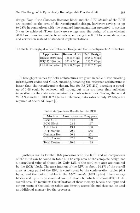
design. Even if the Common Resource block and the LUT Module of the RFUare counted to the area of the reconfigurable design, hardware savings of upto 28% in comparison with the standard implementation presented in section3 can be achieved. These hardware savings ease the design of area efficientASIC solutions for mobile terminals when using the RFU for error detectionand correction instead of standard implementations.
Table 3. Throughput of the Reference Design and the Reconfigurable Architecture
Application Recon. Arch. Ref. Design
RS(255,239) enc. 735.8 Mbps 1568.5 Mbps
RS(255,239) dec. 372.8 Mbps 220.7 Mbps
CRC8 enc./dec. 2512.3 Mbps 13113.7 Mbps
Throughput values for both architectures are given in table 3. For encodingRS(255,239) codes and CRC8 encoding/decoding the reference architecture isfaster than the reconfigurable design, but for RS(255,239) decoding a speed-up of 1,68 could be achieved. All throughput rates are more than sufficientin relation to the data rates required for mobile terminals. Taking the actualWLAN standard IEEE 802.11a as a reference, data rates of only 42 Mbps arerequired at the MAC-layer [6].
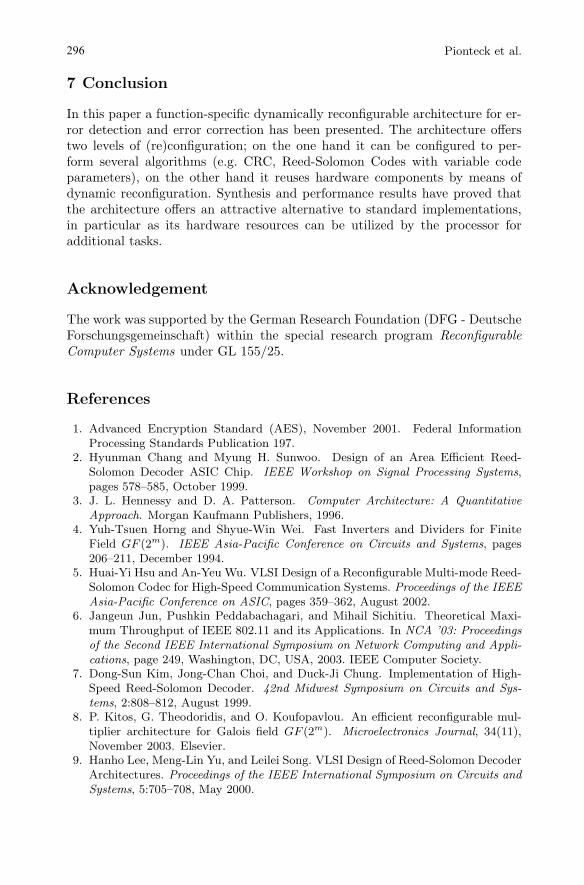
Table 4. Synthesis Results for the RFU
Module Area (normalized) Freq.[MHz]
Basic CPU 44.3 199
ECM Block 22.3 137
AES Block 19.1 138
LUT Module 29.0 588
Common Res. 20.4 201
RFU Control 37.3 244
Total Design 170.0 98
Synthesis results for the DLX processor with the RFU and all componentsof the RFU can be found in table 4. The chip area of the complete design hasa normalized value of about 170. Only 13% of the total chip area are requiredby the ECM block. The area fraction of the RFU is about 74.1% of the overallarea. A huge part of the RFU is constituted by the configuration tables (648bytes) and the look-up tables in the LUT module (1024 bytes). The memoryblocks add up to a normalized area of about 66 which is about 39% of theoverall area. To maximize the utilization of these memory blocks, the input andoutput ports of the look-up tables are directly accessible and thus can be usedas additional memory for the processor.
295On The Design of A Dynamically Reconfigurable Function-Unit
7 Conclusion
In this paper a function-specific dynamically reconfigurable architecture for er-ror detection and error correction has been presented. The architecture offerstwo levels of (re)configuration; on the one hand it can be configured to per-form several algorithms (e.g. CRC, Reed-Solomon Codes with variable codeparameters), on the other hand it reuses hardware components by means ofdynamic reconfiguration. Synthesis and performance results have proved thatthe architecture offers an attractive alternative to standard implementations,in particular as its hardware resources can be utilized by the processor foradditional tasks.
Acknowledgement
The work was supported by the German Research Foundation (DFG - DeutscheForschungsgemeinschaft) within the special research program ReconfigurableComputer Systems under GL 155/25.
References
1. Advanced Encryption Standard (AES), November 2001. Federal InformationProcessing Standards Publication 197.
2. Hyunman Chang and Myung H. Sunwoo. Design of an Area Efficient Reed-Solomon Decoder ASIC Chip. IEEE Workshop on Signal Processing Systems,pages 578–585, October 1999.
3. J. L. Hennessy and D. A. Patterson. Computer Architecture: A QuantitativeApproach. Morgan Kaufmann Publishers, 1996.
4. Yuh-Tsuen Horng and Shyue-Win Wei. Fast Inverters and Dividers for FiniteField GF (2m). IEEE Asia-Pacific Conference on Circuits and Systems, pages206–211, December 1994.
5. Huai-Yi Hsu and An-Yeu Wu. VLSI Design of a Reconfigurable Multi-mode Reed-Solomon Codec for High-Speed Communication Systems. Proceedings of the IEEEAsia-Pacific Conference on ASIC, pages 359–362, August 2002.
6. Jangeun Jun, Pushkin Peddabachagari, and Mihail Sichitiu. Theoretical Maxi-mum Throughput of IEEE 802.11 and its Applications. In NCA ’03: Proceedingsof the Second IEEE International Symposium on Network Computing and Appli-cations, page 249, Washington, DC, USA, 2003. IEEE Computer Society.
7. Dong-Sun Kim, Jong-Chan Choi, and Duck-Ji Chung. Implementation of High-Speed Reed-Solomon Decoder. 42nd Midwest Symposium on Circuits and Sys-tems, 2:808–812, August 1999.
8. P. Kitos, G. Theodoridis, and O. Koufopavlou. An efficient reconfigurable mul-tiplier architecture for Galois field GF (2m). Microelectronics Journal, 34(11),November 2003. Elsevier.
9. Hanho Lee, Meng-Lin Yu, and Leilei Song. VLSI Design of Reed-Solomon DecoderArchitectures. Proceedings of the IEEE International Symposium on Circuits andSystems, 5:705–708, May 2000.
296 Pionteck et al.
On The Design of A Dynamically Reconfigurable Function-Unit
10. Edoardo D. Mastrovito. VLSI Designs for Multiplication over Finite FieldsGF (2m). In AAECC-6: Proceedings of the 6th International Conference, on Ap-plied Algebra, Algebraic Algorithms and Error-Correcting Codes, pages 297–309,London, UK, 1989. Springer-Verlag.
11. H. Michael Ji and Earl Killian. Fast Parallel CRC Algorithm and Implementationon a Configurable Processor. IEEE International Conference on Communications,3:1813–1817, April 2002.
12. Christof Paar and Martin Rosner. Comparison of Arithmetic Architectures forReed-Solomon Decoders in Reconfigurable Hardware. In Kenneth L. Pocek andJeffrey Arnold, editors, IEEE Symposium on FPGAs for Custom Computing Ma-chines, pages 219–225, Los Alamitos, CA, April. IEEE Computer Society Press.
13. Thilo Pionteck, Thorsten Staake, Thomas Stiefmeier, Lukusa D. Kabulepa, andManfred Glesner. Design of a Reconfigurable AES Encryption/Decryption Enginefor Mobile Terminals. Proceedings of the 2004 IEEE International Symposium onCircuits and Systems, 2:545–548, May 2004.
14. Tenkasi V. Ramabadran and Sunil S. Gaitonde. A Tutorial on CRC Computa-tions. IEEE Micro, 8(4):62–75, July 1988.
15. Sourav Roy, Wolfgang Wilhelm Martin Bucker, and B.S. Panwar. ReconfigurableHardware Accelerator for a Universal Reed Solomon Codec. Proceedings of 1stIEEE International Conference on Circuit and Systems for Communication, pages158–161, June 2002.
297