Embed Size (px)
Citation preview
1
On the Design and Implementation of InfrastructureMesh Networks
Krishna N. Ramachandran Milind M. Buddhikot, Girish ChandranmenonUniversity of California Santa Barbara Lucent Bell Labs
[email protected] {mbuddhikot, girishc}@lucent.com
Scott Miller Elizabeth M. Belding-Royer, Kevin C. AlmerothLucent Bell Labs University of California Santa [email protected] {ebelding,almeroth}@cs.ucsb.edu
Abstract—Wireless mesh networking is an exciting new technology thathas applications in defence, metro-area Internet access, and transient net-works (e.g: disaster recovery, conventions). In this paper, we describe thedesign and implementation of a self-configuring, secure infrastructure meshnetwork architecture, called MeshCluster, composed using multi-radio net-work nodes. A subset of radio interfaces on these nodes are used for provid-ing network access to end-devices whereas other radio interface are used forrelaying packets to nearest Internet gateway. We identify four key designproblems: (1) auto-configuration of MeshCluster nodes and relay infras-tructure, (2) single and multipath routing in the relay infrastructure usingrouting metrics, (3) load balancing in the relay infrastructure, and (4) sup-port for end-device mobility across access interfaces of mesh network. Foreach of these problems, we describe in detail our design, prototype imple-mentation, and performance results.
I. INTRODUCTION
In the world of ubiquitous mobile wireless networks that istaking shape, wireless mesh networks are emerging as a sig-nificant new technology. Their promise of rapid deployabilityand reconfigurability makes them suitable for important appli-cations such as disaster recovery, homeland security, transientnetworks in convention centers, hard-to-wire buildings such asmuseums, unfriendly terrains, and rural areas with high costsof network deployment. They can provide large coverage area,reduce “dead-zones” in wireless coverage, lower costs of back-haul connections for base-stations, and improve aggregate 3G,802.11 cell throughput and help reduce end-user battery life.
We distinguish two kinds of mesh networks: (a) Client-meshnetworks [35], [41], [52] wherein end-devices (such as PDAs,laptops) participate in packet forwarding. These networks areinfrastructure less in the sense, operation of client-mesh is notmanaged and monitored by a service provider. They are usefulfor opportunistic[41] or predictable store-and-forward messagetransport [52]. Alternately, when used only for packet forward-ing for multi-radio clients (for example, with 3G and 802.11interfaces), they improve coverage and data rates for wide areacellular service [35]. (b) Infrastructure-mesh networks whereinthe end-devices do not participate in the packet relay and themulti-radio relay nodes are part of the network infrastructure.This paper primarily focuses on this kind of mesh networks.Research Contributions We describe design and implementa-tion of a self-configuring, secure infrastructure mesh networkarchitecture, called MeshCluster, composed using multi-radionetwork nodes. A subset of radio interfaces on the relay nodesare used for providing network access to end-devices whereas
other radio interface are used for relaying packets to nearest in-ternet gateway. We identify and solve four key design problems:(1) auto-configuration of MeshCluster nodes and relay infras-tructure, (2) single and multipath routing in the relay infrastruc-ture using routing metrics, (3) load balancing in the relay infras-tructure to make best use of the channel capacity, interfaces ofmesh network. For each of these problems, we present in detailour design, prototype implementation and performance results.
A. Outline of the Paper
Section II describes in detail our MeshClusters reference ar-chitecture and provides overview of the four design problemswe address. Section III describes our secure auto-configurationscheme. Section IV describes design of the routing architectureand packet forwarding components of MeshCluster. Specifi-cally, we present a new AODV based routing scheme calledAODV-ST that optimizes the common case traffic flow fromrelays to gateway. We describe our load balancing solution inSection V. In Section VI we describe design of three differentschemes for supporting end-device mobility. Section VII de-scribes our prototype implementation of the MeshCluster andSection VIII presents various performance results. We reviewrelated work in Section IX. Finally, Section X presents our con-clusions and on-going work.
II. MeshClusters REFERENCE ARCHITECTURE
*DWHZD\
5HOD\�
5HOD\�$3
5HOD\�$3
5HOD\�$3
������E
������
������
5HOD\�$3
������J
������E
5HOD\�$3
������E
������D
������E
Internet
������D
������D
,27$&OXVWHU0DQDJHU
Fig. 1. MeshCluster: reference architecture

The MeshCluster architecture illustrated in Figure 1 con-sists of two new network elements: the relay and the gatewaynodes. The relay elements are multi-radio systems that sup-port two kinds of wireless network interfaces: access and relay,whereas gateway elements support: relay and Internet back-haul(up-link) interfaces. The end-user Mobile Nodes (MNs) accessnetwork using the access interfaces. The relay interfaces areused to construct a self-configuring, secure, managed, power-adaptive packet forwarding backbone between the relay andgateway nodes. The access links can be based on 3G (e.g:[13])or 802.11[12] standards, whereas the relay links can be basedon 802.16 or 802.11.
The gateways are connected to the Internet via wired (Ether-net) or wireless (1xRTT, EV-DO, 802.16) up-links. The place-ment of relays and gateway nodes depends on the deploymentscenario. For example, in case of municipal metro area networkaimed at providing broadband access to end-users, relays can bemounted on poles and the gateway nodes may be located in datacenters in one of the downtown buildings. The in-building meshnetworks such as enterprise buildings, convention centers, mu-seums may follow similar structured placement. In both thesescenarios, relay nodes will be stationary. On the other hand, inapplications where transient networks are created such as dis-aster recovery, outdoor events, relays may be placed arbitrarilyand may be quasi-stationary. In some cases such as defence ap-plications, where soldiers in vehicles use relays to communicateto their command-and-control via a remote gateway node, relaymobility may be significant. In our work, we do not account forthis scenario.
A MeshCluster-Manager entity, optionally co-located withthe gateways, implements management and monitoring func-tions such as power level and frequency assignment for accessand relay links, load-balancing in the relay cluster, and mobilityand authentication support.Design Problems: We consider following design problems inthe context of MeshCluster architecture with 802.11 based re-lay network and present our solutions: (1) Robust, secure auto-configuration and associated protocol, (2) Packet routing andforwarding in the relay cluster that adapts to failures and net-work conditions such as load and interference and optimizescommon-case traffic, (3) load balancing in the relay infrastruc-ture, and (4) Seamless end-user mobility across the relay nodes.
Due to space constraints we do not consider the problem ofdesigning interference-aware schemes to assign channels to re-lay and access interfaces. Our solution for this challenging prob-lem can be found in our paper [45].
III. SECURE AUTO-CONFIGURATION
MeshClusters uses a secure registration and auto-configurationprotocol to register with the MeshCluster-Manager. This proto-col operates at the IP layer and employs well known ideas in thework of the ZeroConf working group [11] and security proto-cols.
Each relay runs a auto-configuration agent initialized at theboot time. This agent uses one or more of the relay interfaces tolisten to ESSID broadcasts for all ad hoc networks operating inits area. For each ESSID, the agent first joins the ad hoc networkusing the BSSID broadcast. It then picks an IP address from
the zero-configuration address space 169.254.*.* and joins theIP based relay infrastructure. The 16 bits of the selected addresscan be computed using a truncated hash of the MAC address andtime-of-the-day string. Since hash is likely to be unique, prob-ability of the event of multiple nodes booting simultaneouslypicking the same address is significantly low.
The relay node then listens for the gateway advertisements,periodically received and rebroadcast by the relays already partof the MeshCluster. These advertisements contain gateway ca-pability information such as Internet back-haul link speeds, re-lay capacity, best path available through the relay that rebroad-cast the gateway advertisements etc. The agent begins a con-figuration session with one or more gateways selected based oncertain criteria, for example closest gateway — gateway whichcan be reached by a shortest hop-count path or based on capa-bilities such as capacity – least loaded gateway or high capacitygateway.
The auto-configuration protocol supports optional authentica-tion phase in which the agent performs mutual authenticationto the gateway using security credentials such as digital cer-tificates or symmetric key stored in relay in tamperproof hard-ware. The authentication protocol resembles IEEE 802.11i [14]with the key difference that Extensible Authentication Protocol(EAP) packets are IP-encapsulated instead of Ethernet encapsu-lation. Any of EAP schemes that support mutual authenticationand dynamic session security key derivation such as EAP-TLS,EAP-SIM, EAP-AKA may be employed. Using the derived ses-sion keys all packet flow between the relay and gateway canbe encrypted. Also, note that we don’t focus on the securityof the routing protocol in the relay network. We argue that ifeach relay node is authenticated to the gateway, a common dy-namic group key can be securely distributed and used to protectrouting protocol messages. Clearly, to achieve this, relay net-work may operate two ESSIDs, one (e.g: Join Mesh) for traf-fic during authenticate-and-join phase and other (e.g: Authenti-cated Mesh) for post authentication phase.
The relay agent conveys its capabilities such as number andtype of radio interfaces and its observed environment such asvisible neighbors in different frequency ranges, observed inter-ference etc. which may be useful to the gateway for frequencyassignment. The gateway conveys configuration parameters tothe relay such as ESSID for access, frequencies used on relayand access interfaces, power levels to use, mobility method touse, addressing schemes, and any path-specific information. Af-ter the configuration session is complete, the zeroconf address isrelinquished but the security parameters for the session may bepreserved for future reconfigurations.
IV. MESHCLUSTER ROUTING ARCHITECTURE
We considered various design options detailed in the follow-ing:• Layer-2 vs. Layer-3 Routing: Should the mesh routing solu-tion operate at layer 2 or layer 3? Conceivably, the relay net-work could employ layer-2 Ethernet bridging and its associated802.3d spanning tree based forwarding. In this case, the accesscloud of all relays appear as a big layer-2 network at the gatewaynodes. This has the advantage that no access and relay subnetmanagement is required and layer-3 mobility is rather easy to
support. However, such virtualization comes with the cost oftransporting the entire layer-2 packet originating in the accessnetworks to the gateway nodes and a complex virtualizing Eth-ernet layer. Also, naive use of protocols such as DHCP, ARP,RARP that employ layer-2 broadcast can result in bandwidthwastage in the relays.On the contrary, a layer 3 solution does not suffer from thesedrawbacks and also, operates effectively across the differentphysical layer technologies that may be used in a heterogenousmesh network deployment. This requirement is especially im-portant with the rapid innovation in physical layer technologiesand the increasing availability of them in the market.• Leveraging existing Layer-3 wireline routing protocols: Canwe leverage existing wireline routing protocols such as OSPFor RIP for routing within the mesh network? Such an approachif adopted would take advantage of extensively tested and opti-mized wireline protocols for routing within the mesh. Further-more, the task of network management would be greatly sim-plified because of the easy availability of tools that manage andmonitor wireline protocols. However, wireline routing protocolsoftentimes result in relays exchanging a high volume of periodiccontrol messages, which can be a significant traffic overhead inbandwidth constrained wireless mesh networks. Furthermore,wireline routing protocols typically assume that the relays arestatic. This assumption fails to hold in a wireless mesh networkwhere relays can be mobile. Wireline protocols can therefore beinefficient in handling network mobility• Optimizing for common-case traffic: In most deployment sce-narios of mesh networks, a significant portion of traffic in therelay network is due to end-user access to services such as webservers, VPN gateways, database and file servers in the wired in-frastructure such as the Internet or enterprise networks. The datatraffic, such as VOIP, multimedia flows, between end devices inaccess clouds of two different relays will be a small fraction ofthe total traffic. As such optimizing routing to efficiently sup-port forwarding of the common case i.e. the gateway destinedtraffic can improve performance of the relay infrastructure.• Using existing ad hoc routing protocols: Finally, we con-sidered using existing ad hoc routing solutions, such asAODV [44], DSR [29], and OLSR [20] for routing within themesh. These protocols inherently support network mobility andare designed to be low-overhead in their operation. These fea-tures makes them attractive for use in wireless mesh networks.OLSR is a link state routing protocol, analogous to OSPF andrelies on knowledge of complete topology information at allnodes. It is quite efficient if the traffic is distributed equallylikely between any two pairs of nodes which is in contrast to ourcommon case traffic argument. As such OLSR overhead and ca-pability may be a overkill. On the contrary, AODV is a simple,low-overhead, reactive routing protocol that is standardized inIETF and has public domain robust implementations [33], [10],[9]. Therefore, we use AODV as a base MeshCluster routingprotocol. One can conceivably design a hybrid protocol thatreacts to traffic pattern and switches from a AODV based pro-tocol to a OLSR-based protocol in the event traffic distributionbecomes more uniform. We do not consider this mode of oper-ation.
A. Design of AODV-ST
We argue that use of AODV “as-is” leads to a poor mesh rout-ing solution due to following operational deficiencies:1. AODV lacks support for high throughput routing metrics:AODV is designed to support the shortest hop count metric.This metric favors long, low-bandwidth links over short, high-bandwidth links. Furthermore, AODV computes the metric us-ing a broadcast discovery mechanism. Broadcast packets aretypically sent at the lowest data rate and hence the propaga-tion characteristics of higher data rate unicast packets cannotbe accurately predicted using broadcast packets [34]. Becauseof these reasons, AODV can select routes with poor end-to-endthroughput [22].2. AODV lacks an efficient route maintenance technique: Aroute discovered with AODV may no longer be the optimal routefurther along in time. This situation can arise because of net-work congestion or the fluctuating characteristics of wirelesslinks. AODV lacks a provision to re-discover the new opti-mal route. Several proposed techniques [40], [36] overcome thisdrawback by discovering multiple routes to a destination. Theseroutes are then individually monitored for their path character-istics. In a large-scale wireless mesh network, the number ofpaths monitored by the relays can potentially be very large andcan result in high control-traffic overhead.3. AODV route discovery latency is high: AODV is a reactiverouting protocol. This means that AODV does not discover aroute until a flow is initiated. This route discovery latency canbe high in large-scale mesh networks.4. Large routing table sizes: AODV is designed for classic adhoc networks where traffic flows are between nodes or nodeclusters rather than between nodes and Internet hosts. So sim-plistic reuse of AODV implementations result in routing tableentries at relay nodes for all Internet hosts accessed by end de-vices in the access clouds. As such the routing tables can be-come unnecessarily large. AODV must be augmented with ap-propriate tunneling mechanisms to optimize routing table sizefor common case traffic.
Our enhanced AODV-Spanning Tree (AODV-ST) protocoleliminates above limitations as follows: First, it supports highthroughput metrics, such as ETX [21] and ETT [24]. Our currentimplementation supports the ETT metric [24] although othermetrics can be easily supported. Second, it proactively main-tains of spanning trees whose roots are the gateways in themesh network to significantly reduce route discovery latencyand achieve lightweight, soft state route maintenance. Last, itemploys IP-in-IP tunnels to reduce the routing table at relays tosum total of number of relays and access subnets.
Figure 2 illustrates the concept of AODV-ST spanning tree fora sample network of seven relays and two gateways. Each relayin the network lies on two spanning trees ST-1 (shown by solidlines) and ST-2 (shown by dashed lines). The gateways initiatethe creation of the spanning trees by emanating periodic controlmessages that are selectively broadcasted in the network. Eachspanning tree is created such that a relay node on a tree lies onthe optimal path to the gateway corresponding to that tree. Theroute maintenance overhead is kept to a minimum because thepaths to all relays on the spanning trees are proactively main-tained. Furthermore, the route discovery latency is eliminated

Fig. 2. Gateway specific spanning trees.
as each relay in the network is aware of an optimal path to itsdefault gateway. A relay chooses the gateway with which it canachieve the highest capacity (as determined by the routing met-ric) as its default gateway.
For relay-to-relay communication, AODV-ST relies on thereactive route discovery strategy utilized in AODV. Conceptu-ally, AODV-ST is a hybrid routing protocol: it uses a proac-tive strategy to discover routes between commonly used end-points (relay-to-gateway) and uses a reactive strategy for routesbetween less-commonly used end-points (relay-to-relay).
In the following, we first provide a brief overview of AODVand and then discuss the specifics of protocol operation.
B. AODV Overview
AODV is an on-demand ad hoc routing protocol[44]. Forneighbor detection, AODV can use either broadcast HELLOsor link layer feedback. Route discovery is based on a <routerequest, route reply> cycle. Route discovery begins with abroadcast Route Request (RREQ) message containing the des-tination address for the requested route and a RREQ sequencenumber that guarantees loop-free operation. As the RREQ ispropagated throughout the network, each intermediate node cre-ates a reverse route entry towards the originator (source) of theRREQ. An intermediate node forwards only the first RREQ itreceives from the originator. If the destination-only flag is setin the RREQ message, only the destination is allowed to issue aRoute Reply (RREP). If the destination-only flag is not set in theRREQ, an intermediate node is allowed to issue an RREP pro-vided it has an active route towards the destination. The RREPmessage is unicast towards the source along the reverse routesetup during RREQ propagation. As the RREP is propagated,intermediate nodes on the reverse route create a forward routeentry for the destination node in their respective route tables.When an active route breaks, the node in the route that detectsthe break has the option of doing a local repair by finding an-other route towards the destination, or sending a Route Error(RERR) message towards the source to notify it of the break.
Fig. 3. Duplicate route request is rebroadcasted if it is received on a better path.
C. The AODV-ST Routing Protocol
In AODV-ST, the gateways periodically broadcast RREQmessages to initiate the creation of spanning trees. Before aRREQ is broadcasted, a gateway sets the destination-only flagin the RREQ and sets the RREQ destination address to thenetwork-wide broadcast address. These settings differentiatenormal route discovery RREQs from the RREQs for spanningtree creation. A RREQ also contains a metric field which is setto zero by the gateway. When an intermediate relay receives anRREQ, it checks if the RREQ is a gateway-initiated RREQ. Ifthe condition is satisfied, it creates a reverse route to the gate-way provided the RREQ is received on the best known path tothe gateway. The relay can make this determination because ofthe metric field contained in the RREQ. This field is updatedby each intermediate relay to represent the characteristics of thepath it has traversed. The specific handling of the field at eachrelay is dependent on the path metric being used. To simplifythe explanation, we postpone the discussion on metric handlingto the next subsection. Once a relay creates a reverse route entryfor the gateway, it sends a gratuitous RREP back to that gate-way. This gratuitous RREP also has a metric field that is set tozero initially. The field is updated at every intermediate relayon the path to the gateway. When an intermediate relay receivesthe gratuitous RREP, it creates a forward route to the originatingrelay. It updates the path metric to the originating relay with themetric value contained in the gratuitous RREP.
A relay re-broadcasts a gateway initiated RREQ only if thepath traversed by the RREQ is the best known path to the relay.Note that an intermediate relay does not wait until it receivesall RREQs before picking the best one to rebroadcast. This isrequired to reduce the route discovery latency. This would meanthat an upstream relay could receive a duplicate RREQ fromthe same downstream relay if the duplicate RREQ representsa better reverse path. This mode of operation is illustrated inFigure 3. Relay D in the figure receives two RREQs from thegateway G that traverse two different paths a and b where a isbetter than b. Assume that the RREQa is slightly delayed withrespect to RREQb. When D receives RREQb, it rebroadcasts itas it arrived on the first path known to it. However, when thedelayed RREQa is received, D rebroadcasts it because it arrivedon the better path. Relay U therefore receives two duplicateRREQs from D.
As the RREQ is broadcasted hop-by-hop throughout the meshnetwork, the spanning tree is implicitly formed through the cre-
ation of reverse routes to the gateway at the relays. The timeinterval between successive gateway-initiated RREQs is set toten seconds in our implementation. We empirically determinedthis interval to be a good setting. Each relay on receiving thesuccessive RREQs updates its reverse routes based on the met-ric field contained in them.
For relay-to-relay communication, a relay node initiates aRREQ with the destination flag set and the destination addressset to the address of the node to be reached. The destination flagis set because the most up-to-date path information is requiredat the source during path selection. The handling of the RREQsat the intermediate nodes is similar to the procedure describedabove.
D. Routing Metric Support in AODV-ST
A routing metric used with AODV-ST must satisfy two re-quirements: First, the metric must increase in value with in-creasing hopcount. This is required to prevent loop-free pathselection. Second, it must be a bi-directional metric, i.e., themetric must give equal weightage to a path’s performance in theforward and reverse directions. This is necessary for two rea-sons. First, TCP flows are bi-directional in nature. Therefore,both directions of a path must be considered during route selec-tion. Second, AODV-ST creates a reverse route to a gatewayupon receiving a RREQ that traverses in the forward directionfrom the gateway to the relays. Therefore, the metric must repre-sent a path’s performance in both directions, otherwise AODV-ST can select uni-directional paths.
Our current implementation of AODV-ST supports the Ex-pected Transmission Time (ETT) metric [24]. ETT is a measureof the expected time needed to successfully transmit a packetof a fixed length, s, on a link. It yields high throughput pathsbecause it selects a path with the least delay.
ETT is given as (etx ∗ s/b) where etx is the expected num-ber of transmissions necessary to send a packet on the link [21];s is the size of the packet (set to 1024 bytes in our implemen-tation); and b is the bandwidth of the link. etx is computed byissuing periodic broadcast probe messages (sent every second inour implementation) in the forward and reverse directions andby measuring the corresponding forward delivery ratio (df ) andthe reverse delivery ratio (dr) for a predetermined time interval.This time interval is set to ten seconds in our implementation.The etx for the link is then given as etx = 1/(df ∗ dr). Thelink bandwidth, b, is determined using feedback from the radiodriver. We modified the hostap driver [2] used in our implemen-tation to support the feedback of the link date rate every second.The driver computes per-second link data rates by averaging thedata rates of packets that traverse a link in the one second in-tervals. Where a driver does not provide rate feedback, we relyon packet-pair probing [32] to estimate bandwidth. In our im-plementation of this technique, a pair of packets, one small (134bytes) and the other large (1200 bytes), are sent back-to-backevery minute for ten minutes in both directions of the link. Assoon as the smaller size packet is received, a timer is started tomeasure the delay incurred in receiving the larger packet. Wechoose the minimum of ten delay samples to estimate the linkbandwidth. The link bandwidth then is simply the ratio of packetsize and minimum delay. We use the minimum delay sample to
reduce any adverse impact queuing delays have on the transmis-sion of the packet pairs.
The ETT metric, however, is not an optimal choice in a multi-radio wireless mesh network because it does not consider thefrequency diversification of a path during path selection [24].This can lead to sub-optimal routing in our current implementa-tion. We are exploring various techniques to enhance the ETTmetric to account for frequency diversification. One possibleapproach is to use the Weighted Cumulative Expected Trans-mission Time (WCETT) metric [24]. WCETT requires knowl-edge about each link in the path, such as the link’s delay andits assigned frequency. This requirement can be easily satis-fied by using a link-state routing protocol such as OLSR [20] orOSPF [37]. On the other hand, AODV-ST is a distance-vectorrouting protocol in which link-level information is not dissem-inated by design. This complicates the support of WCETT inAODV-ST. As future work, we plan to incorporate in AODV-STa simple, low-overhead scheme to accumulate link-level infor-mation so that a metric like WCETT can be easily supported.We are currently evaluating a link-level accumulation schemesimilar to the one used by AODV-bis [43].
V. MESHCLUSTER LOAD BALANCING
A. Load Balancing Defined
Load balancing is a desirable feature to have in a wirelessmesh deployment. It reduces congestion in the network, in-creases network throughput, and prevents service disruption incase of failure. Load balancing in wireless mesh networks canbe defined in the following two ways:• Path load balancing: Path load balancing can improve net-work performance and reliability by distributing traffic amonga set of diverse paths. There are proposals to achieve path loadbalancing in wireline networks [31], [19] and multi-hop wirelessnetworks [38]. Pearlman et. al. [42] show that path load bal-ancing provides negligible performance improvement in wire-less multi-hop networks because of route coupling of candidatepaths between common endpoints. Route coupling is a resultof the geographic proximity of the candidate paths. This canlead to self-interference between those paths and can thereforeadversely impact performance.• Gateway load balancing: In this interpretation of load balanc-ing, traffic is distributed among a set of gateways in the wire-less mesh network, i.e., one of several gateways is chosen as theegress point for flows originating from the network. We believethat the performance improvement with gateway load balanc-ing will be greater than with path load balancing because routecoupling of paths to different gateways from an endpoint in themesh is expected to be less in a well-planned deployment. Forthis reason, the MeshCluster architecture supports gateway loadbalancing. To the best of our knowledge, there is no prior workon gateway load balancing for wireless mesh networks.
B. Gateway Load Balancing Protocol
This subsection provides an overview of the gateway load bal-ancing solution supported by the MeshCluster architecture.
An access relay (relay that is also an access point) lies on thespanning trees corresponding to the gateways in the network.

The spanning tree formation is described in Section IV. Theaccess relay then selects one of the discovered gateways as itsdefault gateway. The default gateway is the one with whichthe relay can achieve the highest capacity (as determined by therouting metric). The access relay typically uses the default gate-way as the egress point for all the flows initiated by it.
Each access relay in the network also monitors the quality ofthe best path to each of its gateways. The best path is simplythe path on the spanning tree computed for that gateway. Asdescribed in Section IV, all paths on a spanning tree created fora gateway represent the optimum paths (in terms of the routingmetric) from the gateway to the relays on that tree. The pathquality is monitored using a simple round trip time (RTT) prob-ing tool. The tool reports RTT values for each of the gatewaysin the network. The gateway with the least-delay is designatedas the least-loaded gateway. In an unloaded wireless mesh net-work, the default gateway will typically be the least-loaded gate-way. Note that this is only true when the routing metric used tocompute the spanning metrics is a delay metric. When an ac-cess relay detects that its least-loaded gateway and its defaultgateway are different, it infers that there is congestion in thenetwork on the path leading to its default gateway. In this case,all the new flows initiated by the relay utilize the least-loadedgateway as their egress point.
The relay does not migrate any of its existing flows to theleast-loaded gateway. This is required in any MeshCluster de-ployment that does network address translation (NAT) at thegateways, otherwise flow migration can result in the disruptionof flows unless the per-flow state at the network address trans-lators (NATs) is also migrated. We note that the migration ofper-flow state across NATs is a non-trivial problem to solve.Therefore, we mandate that the migration of existing flows beavoided. This requirement can be relaxed if the mesh relays areassigned globally routable addresses in which case network ad-dress translation would not be required at the egress points.
The migration of flows to the least-loaded gateway can resultin route-flapping. Route-flapping occurs when several flows mi-grate to a least-loaded gateway and this results in the previouslyused gateway becoming unloaded. The relays detect the changein status and start utilizing the original gateway as the egresspoint. The switch now results in the second gateway becomingunloaded. Route-flapping can prevent both egress points frombeing used equally and can also result in frequent packet re-ordering. This problem of route-flapping is more likely to occurwhen existing flows in the network are also allowed to migrateacross gateways. We are currently investigating a gateway ar-bitration protocol to alleviate the route flapping problem. Ourpreliminary idea is to place an arbitration manager at each gate-way in the network. Agents situated at the access relay contactthe arbitration manager before switching flows. Because the ar-bitration manager is aware of flow migration requests, it can in-telligently migrate flows in order to mitigate route-flapping.
VI. MOBILITY SUPPORT
It is essential to support seamless mobility of users within themesh network. There are several mobility mechanisms that canbe employed, such as, mobile IP [25], simple DHCP based mo-bility, and Mobile NAT [18]. We describe these three in detail.
Mobile IP based domain mobility
InternetGateway
Relay
802.11b
802.16
Relay
AP
802.11b
802.11a
802.11a
Home Agent
Relay
APFA
FA
Relay
Relay
APFA
Radius
Server
Mobility
Fig. 4. Using Mobile IP to support domain mobility
Mobile-IP (MIP) [25] has been standardized for Internet scalemobility for end-hosts. We can easily employ the same solu-tion for domain mobility in the context of mesh networks (Fig-ure 4). In this case, the MIP Home Agent (HA) is co-locatedwith the gateway nodes whereas the MIP Foreign Agent (FA)functionality is instantiated in the access network in each re-lay element. The enduser device (MN) is assigned a home IPaddress (HADDR), statically during configuration, or using dy-namic home address assignment. The MN detects a change inlayer-2 association by monitoring the MAC address of the ac-cess points in the relay. In the event of access point switch, themobile IP client in the MN initiates a mobile IP registration (so-licitation, advertisement, and registration) with the FA on thenew access point. Once the registration is complete, the homeagent at the gateway node will tunnel all traffic for the mobile tothe new foreign agent.
In the event, HA uses only private addresses, the MIP is usedas a domain level micro-mobility method. If HA employs pub-lic addresses, then the MN is reachable from the public Internet.The drawbacks of this solution are: (1) need for a specializedMIP client software on each relay node and need for FA sup-port on the relay. If the MIP client implements co-located FAmode, FA support at the relay is optional. (2) Associated man-agement overhead for configuration of HA, FA and HADDR. (3)Slow handoff latencies unless cross-layer indication and otherfast handoff mechanisms are employed.
MobileNAT based mobility
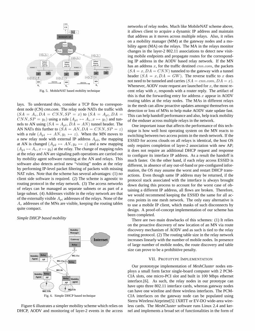
MobileNAT[18] is a new technique that uses Network Ad-dress Translation (NAT) operations and specialized mobilityagents in the signaling path to achieve transparent mobility. Itcan be employed to support intra-domain mobility in mesh net-works. The key ideas here are illustrated in Figure 5. The gate-way node here serves as the Anchor Node (AN) which NATsall enduser traffic to external Internet hosts (such as cnn.com).From the perspective of the external hosts all traffic is an-chored on the public IP addresses of the gateway (AN) node.The MN acquires a fixed IP address Av when it first bootsand associates with one of the relays. MobileNAT allows itto hold this address as it roams across access networks of re-
CNN
CN
DOMAIN AN
moves
Av
AP
MN
AP
MN
AP AP
SubnetRouter
with AN
Av
MN
AP AP
SubnetRouter
with AN
Av
Ap1CNN y1
moves
AvCNN x AvCNN x
Ap2CNN y2
Ap3CNN y3
AANCNN z
AvCNN x
SUBNET 1 SUBNET 3SUBNET 2
Router Router
Router
SubnetRouter
with AN
Fig. 5. MobileNAT based mobility technique
lays. To understand this, consider a TCP flow to correspon-dent node (CN) cnn.com. The relay node NATs the traffic with(SA = Av , DA = CNN, SP = x) to (SA = Ap1, DA =CNN, SP = y1) using a rule (Ap1 7→ Av, x 7→ y1) and tun-nels to AN using (SA = Ap1, DA = AN) tunnel header. TheAN NATs this further to (SA = AN, DA = CNN, SP = z)with a rule (Ap1 7→ AN, y1 7→ z). When the MN moves toa new relay node with external IP address Ap2, the mappingat AN is changed (Ap2 7→ AN, y2 7→ z) and a new mapping(Ap1 7→ Av , x 7→ y2) at the relay. The change of mapping rulesat the relay and AN are signaling path operations are carried outby mobility agent software running at the AN and relays. Thissoftware also detects arrival new “visiting” nodes at the relayby performing IP-level packet filtering of packets with missingNAT rules. Note that the scheme has several advantages: (1) noclient side software is required. (2) The scheme is agnostic torouting protocol in the relay network. (3) The access networksof relays can be managed as separate subnets or as part of alarge subnet. (4) Addresses visible in the relay network are thatof the externally visible Api addresses of the relays. None of theAv addresses of the MNs are visible, keeping the routing tablesquite compact.
Simple DHCP based mobility
InternetRelay
Relay
AP
802.11b
802.16
Relay
AP
Relay
AP
802.11b
802.11a
802.11a
MobilityAgent
Mobility agent
Relay
Mobility Agent
Mobility Manager
Gateway
Fig. 6. Simple DHCP based technique
Figure 6 illustrates a simpler mobility scheme which relies onDHCP, AODV and monitoring of layer-2 events in the access
networks of relay nodes. Much like MobileNAT scheme above,it allows client to acquire a dynamic IP address and maintainthat address as it moves across multiple relays. Also, it relieson a mobility manager (MM) at the gateway nodes and a mo-bility agent (MA) on the relays. The MA in the relays monitorchanges in the layer-2 802.11 associations to detect new visit-ing mobile endpoints and propagate routes for the correspond-ing IP address in the AODV based relay network. If the MNhas an address x, for the traffic destined cnn.com, the packets(SA = x, DA = CNN) tunneled to the gateway with a tunnelheader (SA = x, DA = GW ). The reverse traffic to x doesnot need to be tunneled and carries (SA = cnn.com, DA = x).Whenever, AODV route request are launched for x, the most re-cent relay with x, responds with a router reply. The artifact ofthis is that the forwarding entry for address x appear in AODVrouting tables at the relay nodes. The MAs in different relaysin the mesh can allow proactive updates amongst themselves ondetection or loss of MNs to help make AODV state update fast.This can help handoff performance and also, help track mobilityof the enduser across multiple relays in the network.
One important issue that affects the performance of this tech-nique is how well host operating system on the MN reacts toswitching between two access points in the mesh network. If theESSID for access clouds on all relays is identical, the host OSonly requires completion of layer-2 association with new AP;it does not require an additional DHCP request and responseto configure its interface IP address. As a result the handoff ismuch faster. On the other hand, if each relay access ESSID isdifferent, in absence of any out-of-band or pre-configured infor-mation, the OS may assume the worst and restart DHCP trans-actions. Even though same IP address may be returned, if theprotocol stack associated with the interface is always broughtdown during this process to account for the worst case of ob-taining a different IP address, all flows are broken. Therefore,we would recommend keeping the ESSID the same for all ac-cess points in one mesh network. The only easy alternative isto use a mobile IP client, which masks of such disconnects bydesign. A proof-of-concept implementation of our scheme hasbeen completed.
There are two main drawbacks of this schemes: (1) It relieson the proactive discovery of new location of an MN via routediscovery mechanism of AODV and as such is tied to the relayrouting protocol. (2) The routing table size in the relay networkincreases linearly with the number of mobile nodes. In presenceof large number of mobile nodes, the route discovery and tablesize can prove to be a prohibitive penalty.
VII. PROTOTYPE IMPLEMENTATION
Our protototype implementation of MeshCluster nodes em-ploys a small form factor single-board computer with 2 PCM-CIA slots, one micro-PCI slot and built in 100 Mbps ethernetinterface.[6]. As such, the relay nodes in our prototype canhave upto three 802.11 interface cards, whereas gateway nodescan have one wireline and three wireless interfaces. The PCM-CIA interfaces on the gateway node can be populated usingSierra Wireless/Airprime[5] 1XRTT or EV-DO wide-area wire-less cards. The MeshCluster software runs Linux 2.4 and ker-nel and implements a broad set of functionalities in the form of

b) IOTA Gateway
Fig. 7. MeshCluster node
modules, such as AODV-ST relay module based on the NISTAODV kernel implementation, an enhanced 802.11 hostap ac-cess point, IP services modules (QoS, DHCP, NAT, DynamicFirewall), Security and Accounting (RADIUS server/client),web services (web portal, caching, web-based configuration),and mobility support (Mobile IP, and MobileNAT variant).
We also used a mobility client software that manages mul-tiple network interfaces to support automated interface selec-tion and seamless mobility handoff using MobileIP. The mobil-ity client, developed as a part of our research on 802.11 and 3Gintegration, includes a complete Mobile-IP stack that supportsper-subnet FA [50] and co-located FA [50] modes and performsmost of the mobility management[17]. Current version of mo-bility client does not integrate the new mobility technique de-scribed in Section VI.
VIII. PERFORMANCE EVALUATION
This section presents results from our evaluation of the Mesh-Cluster architecture. We first present our goals and the evalua-tion methodology.
A. Goals and Evaluation Methodology
Our goal is to evaluate the individual components of the archi-tecture such as the mesh auto-configuration scheme, the routingsolution, the load balancing scheme, and the mobility manage-ment schemes. Due to space constraints, we omit results fromour evaluation of the load balancing scheme. We plan to presentthose results in a forthcoming paper.
For the auto-configuration scheme, we are interested in ana-lyzing the time it takes for all devices in the mesh network tojoin the network. We vary the number of interfering networks inthe vicinity of the mesh to study the impact of such networks onthe time taken for auto-configuration to complete. We rely on asimulation-based evaluation because it allows us to easily con-trol the number of interfering devices in our analysis. Achievingthis objective in a testbed environment is challenging. We utilizethe Qualnet simulator for this evaluation.
To gauge the performance improvements with the MeshClus-ter routing solution, we compare AODV-ST against AODV interms of end-to-end TCP throughput on the UCSB Meshnet [8],a twenty-five node wireless multi-hop testbed deployed in a five-floored office building on the campus of UC Santa Barbara. We
utilize twenty of them that are deployed on the first four floorsin our comparision. Figure 8 shows a map of the floors andthe location of the testbed devices on the various floors. Thetestbed devices are of two types. The ones indicated by squaresin the figure are small form-factor desktop computers runningLinux 2.4.27. Each of these computers is equipped with a En-Genius 2511-CD IEEE 802.11b radio. The ones indicated bycircles are Linksys WRT54G wireless routers, each equippedwith a Broadcom IEEE 802.11b/g radio. They are installed withthe OpenWRT Linux distribution and utilize Linux 2.4.20 as thekernel.
Finally, we evaluate the mobility management schemes byutilizing a smaller testbed consisting of four nodes in a linetopology A - B - C - D. Nodes A, B, C, and D, are IBM ThinkpadT21 laptops running Linux 2.4.27. Nodes A and B are equippedwith a single radio whereas C and D are equipped with two ra-dios each. A is designated as the gateway, B as a relay, and C andD as access relays. All the radios used in this setup are EnGenius2511-CD IEEE 802.11b radios. Our goal for this evaluation is tocompare the two mobility management schemes in terms of thedelay associated in handing off from one access relay to another.
B. Results
Auto-Configuration Scheme: Our simulation environmentis a network topology consisting of 30 mesh relays randomlydistributed in a terrain of 1000x1000m. All relays are equippedwith a single IEEE 802.11a radio. At the start of a simulation,each relay randomly picks a channel to operate on. One of therelay devices is designated as a gateway. The gateway initiatesperiodic advertisements every second to indicate its presence.An advertisement is embedded in a AODV Hello message andis propagated hop-by-hop throughout the network as Hello mes-sages are exchanged between relays that have joined the meshnetwork. We implemented a layer 2 beaconing mechanism thata relay uses to issue periodic link-layer frames (every 100 msec)that contain the ESSID (name) of the network it has joined. Thislink-layer frame resembles IEEE management frames that areexchanged between stations that are part of a IEEE 802.11 adhoc network. At the start of the simulation, only the gatewayis assigned an ESSID. A relay listens for 200 milliseconds oneach supported channel (12 in all in our simulation) in orderto receive ESSID advertisements. It then joins each discoverednetwork for a period of three seconds to listen to gateway ad-vertisements. If a relay receives gateway advertisements on aparticular ESSID, it attempts to register with the gateway. Ifthe registration is successful, the relay is a part of the mesh net-work. The relay then propagates the gateway advertisements toits neighbors using AODV Hello messages.
Using the above described simulation setup, we measured thetime taken for all the relays to join the mesh network in presenceof varying degress of interference. We introduced interferenceby varying the number of devices external to the mesh networkfrom zero to fifty in increments of ten. Each interfering device atthe start of a simulation randomly selects a channel and ESSIDname to operate on.
Figure 9 represents the time (on Y axis) taken by the thirtydevices (on X axis) to join the mesh network. In the absence ofinterfering devices, the mesh relays join the network within 20
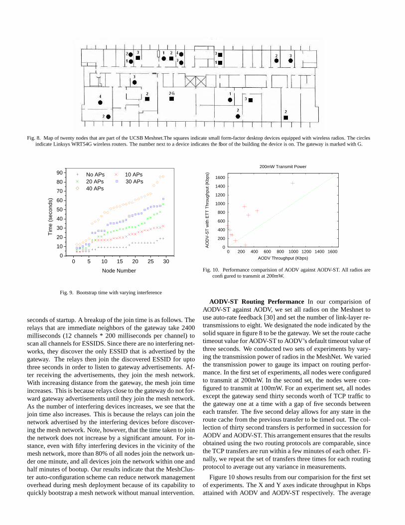
Fig. 8. Map of twenty nodes that are part of the UCSB Meshnet.The squares indicate small form-factor desktop devices equipped with wireless radios. The circlesindicate Linksys WRT54G wireless routers. The number next to a device indicates the floor of the building the device is on. The gateway is marked with G.
0 5 10 15 20 25 30 0
10
20
30
40
50
60
70
80
90
Tim
e (s
econ
ds)
Node Number
No APs 10 APs 20 APs 30 APs 40 APs
Fig. 9. Bootstrap time with varying interference
seconds of startup. A breakup of the join time is as follows. Therelays that are immediate neighbors of the gateway take 2400milliseconds (12 channels * 200 milliseconds per channel) toscan all channels for ESSIDS. Since there are no interfering net-works, they discover the only ESSID that is advertised by thegateway. The relays then join the discovered ESSID for uptothree seconds in order to listen to gateway advertisements. Af-ter receiving the advertisements, they join the mesh network.With increasing distance from the gateway, the mesh join timeincreases. This is because relays close to the gateway do not for-ward gateway advertisements until they join the mesh network.As the number of interfering devices increases, we see that thejoin time also increases. This is because the relays can join thenetwork advertised by the interfering devices before discover-ing the mesh network. Note, however, that the time taken to jointhe network does not increase by a significant amount. For in-stance, even with fifty interfering devices in the vicinity of themesh network, more than 80% of all nodes join the network un-der one minute, and all devices join the network within one andhalf minutes of bootup. Our results indicate that the MeshClus-ter auto-configuration scheme can reduce network managementoverhead during mesh deployment because of its capability toquickly bootstrap a mesh network without manual intervention.
0
200
400
600
800
1000
1200
1400
1600
0 200 400 600 800 1000 1200 1400 1600
AO
DV
-ST
with
ET
T T
hrou
ghpu
t (K
bps)
AODV Throughput (Kbps)
200mW Transmit Power
Fig. 10. Performance comparision of AODV against AODV-ST. All radios areconfigured to transmit at 200mW.
AODV-ST Routing Performance In our comparision ofAODV-ST against AODV, we set all radios on the Meshnet touse auto-rate feedback [30] and set the number of link-layer re-transmissions to eight. We designated the node indicated by thesolid square in figure 8 to be the gateway. We set the route cachetimeout value for AODV-ST to AODV’s default timeout value ofthree seconds. We conducted two sets of experiments by vary-ing the transmission power of radios in the MeshNet. We variedthe transmission power to gauge its impact on routing perfor-mance. In the first set of experiments, all nodes were configuredto transmit at 200mW. In the second set, the nodes were con-figured to transmit at 100mW. For an experiment set, all nodesexcept the gateway send thirty seconds worth of TCP traffic tothe gateway one at a time with a gap of five seconds betweeneach transfer. The five second delay allows for any state in theroute cache from the previous transfer to be timed out. The col-lection of thirty second transfers is performed in succession forAODV and AODV-ST. This arrangement ensures that the resultsobtained using the two routing protocols are comparable, sincethe TCP transfers are run within a few minutes of each other. Fi-nally, we repeat the set of transfers three times for each routingprotocol to average out any variance in measurements.
Figure 10 shows results from our comparision for the first setof experiments. The X and Y axes indicate throughput in Kbpsattained with AODV and AODV-ST respectively. The average

0
200
400
600
800
1000
1200
1400
1600
0 200 400 600 800 1000 1200 1400 1600
AO
DV
-ST
with
ET
T T
hrou
ghpu
t (K
bps)
AODV Throughput (Kbps)
100mW Transmit Power
Fig. 11. Performance comparision of AODV against AODV-ST. All radios areconfigured to transmit at 100mW.
throughput of the good paths comprising of only one hop on themeshnet is greater than 4000 Kbps. AODV-ST offers no perfor-mance improvement over AODV because both protocols choosethe one hop path for the data transfer. Five such data points arenot depicted in the graph in order to improve the clarity of thegraph in the lower throughput ranges. From the figure, it is clearthat AODV-ST offers significant throughput improvements overAODV. Note the region of the graph near zero on the X axis.Several data points in this region indicate that AODV-ST offersgreater than 250 Kbps throughput, where as with AODV the at-tained throughput is less than 70 Kbps. This is because AODVuses the shortest hop count metric which typically selects pathscomprised of long, low-bandwidth links; AODV-ST on the otherhand utilizes the ETT metric which takes into acccount link re-liability and link bandwidth during path selection, which resultsin AODV-ST selecting a least-delay path. The ETT metric, how-ever, can result in AODV-ST selecting higher hop-count pathsthan paths selected using the shortest hop-count metric as withAODV. We verified that this is true for the data points in the fig-ure. In a majority of the cases, the hop-count with AODV-ST isone more than with AODV; for the data points close to zero onthe X axis, the hop-count with AODV-ST is often two more thanwith AODV.
Figure 11 shows results from our comparision with the radiotransmit power set to 100mW. Again we omit five data pointswith throughput above 4000 Kbps to improve the clarify of thefigure. AODV-ST results in improved performance over AODV.However, the performance improvements are not as significantas in the above case. This is because of the effect transmitpower has on the neighbor connectivity of the meshnet nodes.Because of the reduced transmit power, the neighbor connectiv-ity is sparser than in the 200mW case. As a result, the numberof candidate paths available from a source to a destination issmaller and is of higher hop-count. As a result, there is a higherlikelihood that AODV and AODV-ST choose paths that overlapwith each other. We validated this to be the case by compar-ing the paths selected using AODV and AODV-ST and found anincrease in path overlap. We believe that the increased overlapresults in comparable throughputs with the two protocols.
Evaluation of Mobility Schemes: We implemented both mo-bile IP based mobility and DHCP based mobility. As discussed
Fig. 12. Mobile-IP Latency
Fig. 13. Simple-IP Latency
in Section VI, we deployed a foreign agent in each of the accessnodes, and a home agent in the gateway node. In the case ofsimple IP based mobility, we implemented a mobility agent inthe access nodes. This agent gets indication from layer-2 thata new node has joined. Figure 12 shows the switching delayfor mobile IP based scheme, and Figure 13 shows the delay forDHCP based mobility.
In mobile IP based mobility, the client resumed its networkconnection in 760ms, and in simple IP mobility, the client re-sumed its network connection in the new network in 5.2 sec-onds. The individual components of latency are as shown inFigure 12 and Figure 13. As seen in the figure, the layer-2 asso-ciation is accomplished in less than 200ms, however, the layer-3attachment takes much longer.
Although we expected better latency in simple IP basedscheme, we did not observe this in practice. This is due tothe specific way Windows DHCP client handles a new attach.In Windows, the client restarts the entire DHCP process if thewireless network card changes point of attachment. As a re-sult, the Windows client starts off a DHCP DISCOVER, OF-FER, REQUEST, ACK sequence. We can attempt to cut downthe delay between DISCOVER and OFFER, however, the delaybetween OFFER and REQUEST is internal to Windows. If itcould change the process, and simply verify that it is attached tothe same IP subnet and maintain the connections, it would en-able a simple seamless mobility with low latency. We intend toexplore these options for improving DHCP based mobility, es-pecially since it does not require an added client in the enduserdevice.
IX. RELATED WORK
There exists a lot of related work that is in some way con-cerned with wireless mesh networks. While it is not possibleto summarize all the proposals because of space constraints, wepresent a representative sample below.
Considerable research has addressed the problem of routingin wireless multi-hop networks [20], [26], [29], [44]. Ear-lier works focused on wireless ad hoc networks where energylimitation and mobility are major constraints. These propos-als utilize the shortest hop count metric as the path selectionmetric. This metric has been shown to result in poor networkthroughput because it favors long, low-bandwidth links overshort, high-bandwidth links [22], [34]. More recent proposalsaim to improve routing performance by utilizing route selectionmetrics [21], [23], [24].
Wireless multi-hop networks suffer from serious capacitydegradation due to the half-duplex nature of the wirelessmedium [27]. Several proposals aim to alleviate this capacityproblem by revamping the MAC layer to support the intelligentselection of a wireless channel during packet transmission [15],[28], [39], [49]. Other proposals aim to improve the capac-ity by equipping relays with multiple radios [24], [45], [47],[51]. Some wireless mesh hardware vendors also offer multi-radio mesh routers that utilize proprietary channel assignmentschemes [1], [3], [7].
Little work has focused on developing system architecturesfor wireless mesh networks. Bicket et. al. evaluate the MITRoofnet architecture [16] and find that their Cambridge Roofnetdeployment can provide users of the network with usable per-formance despite lack of careful planning in deployment. TheMeshCluster architecture is similar in spirit to the MIT Roofnetarchitecture. The key distinguishing aspect between the two ar-chitectures is that the Roofnet architecture is specifically tar-geted for community networks where relays are expected to bestatic and end-user mobility is minimal; the MeshCluster ar-chitecture is also well-suited for deployments where relays andend-users are mobile. Examples of such deployments includetransient networks deployed for search-and-rescue and militaryoperations.
There have been a number of testbed multi-hop wireless net-work deployments [4], [8], [24], [48]. A majority of such de-ployments are intended for conducting research on multi-hopwireless networks. There is also a growing deployment of com-mercial wireless mesh networks around the world. Such de-ployments support last-mile broadband connectivity, emergencyservices, and remote monitoring applications. Some of the hard-ware vendors that offer deployment services include TroposNetworks, Strix Systems, and Firetide Inc.
X. CONCLUSIONS
Wireless mesh networking has emerged as a promising newtechnology for the rapid deployment of wi reless networks forapplications such as search and rescue, home land security, andmetro-scale b roadband connectivity. Although several meshnetworking hardware vendors are offering services fo r the de-ployment of wireless mesh networks, the research communityin general has paid little att ention to the design of architectures
and systems that can fulfill the promise of this new techno logy.The MeshCluster architecture described in this paper is our at-tempt at fulfilling this gap.
We identified the following critical challenges that must beaddressed for mesh networking to rea ch its full potential: (1)mesh network auto-configuration, (2) high-throughput packetrouting, ( 3) mesh network load balancing, and (4) a mobilitymanagement framework that can ensure seamless user mobilityin the mesh network. We described in detail the design, imple-mentation, and evaluat ion of components of the MeshClusterarchitecture that address these challenges.
As future work, we are investigating the use of multiple ra-dios to improve the capacity of the MeshCluster architecture.Currently, we are implementing an interference-aware channelassignment s cheme that takes into account interference from co-located wireless networks during channel assig nment. We arealso developing a routing solution that is optimized for multi-radio, multi-channel wireless mesh networks. Our initial analy-sis indicates that reactive routing protocols such as AODV andDSR may suffer from control packet flooding problems in amulti-radio, multi-channel network because of the multitude ofpaths that are available in such networks. We are also integrat-ing mesh network management and monitoring utilities such asDAMON [46] into the MeshCluster architecture to assist in themanagement and monitoring of wireless mesh networks. Ourgoal is to offer the MeshCluster architecture for download to theresearch community so that it can leverage this architecture forresearch and development purposes.
REFERENCES
[1] BelAir Networks. http://www.belairnetworks.com.[2] HostAP Driver. http://hostap.epitest.fi.[3] MeshDynamics. http://www.meshdynamics.com.[4] MIT roofnet. http://www.pdos.lcs.mit.edu/roofnet/.[5] Sierra wireless (http://www.sierrawireless.com).[6] Soekris, inc. (http://www.soekris.com).[7] StrixSystems. http://www.strixsystems.com.[8] UCSB MeshNet Project. http://moment.cs.ucsb.edu/meshnet.[9] UoB AODV Implementation. http://www.aodv.org.[10] Uppsala University AODV Implementation. http://core.it.uu.se/AdHoc.[11] Zero configuration working group (http://www.zeroconf.org/).[12] Wireless LAN Medium Access Control (MAC) and Physical Layer (PHY)
specifications. ANSI/IEEE Std 802.11: 1999 (E) Part 11, ISO/IEC 8802-11, 1999.
[13] TIA/EIA/IS-835B - cdma2000 Wireless IP Network Standard. , ThirdGeneration Partnership Program 2 (3GPP2), 2000.
[14] Part 11: Wireless MAC and physical layer specifications:Specification ofEnhanced Security. Technical report, IEEE P802.11i, Novemeber 2002.
[15] P. Bahl, R. Chandra, and J. Dunagan. SSCH: Slotted Seeded ChannelHopping For Capacity Improvement in IEEE 802.11 Ad Hoc WirelessNetworks. In ACM MobiCom, Philadelphia, PA, September 2004.
[16] J. Bicket, D. Aguayo, S. Biswas, and R. Morris. Architecture and Evalua-tion of an Unplanned 802.11b Mesh Network. In ACM Mobicom, Cologne,Germany, September 2005.
[17] M. Buddhikot, G. Chandranmenon, S. Han, Y. W. Lee, S. Miller, andL. Salgarelli. Integration of 802.11 and Third Generation Wireless DataNetworks. In IEEE INFOCOM 2003, April. 2003.
[18] M. Buddhikot, A. Hari, K. Singh, and S. Miller. MobileNAT: A NewTechnique for Mobility Across Heterogeneous Address Spaces. SpecialIssue of ACM/Kluwer Journal on Mobile Networks.
[19] Robert Carter and Mark Crovella. Server Selection Using Dynamic PathCharacterization in Wide-Area Networks. In IEEE Infocom, Kobe, Japan,April 1997.
[20] T. Clausen and P. Jacquet. Optimized link state routing protocol (OLSR).Internet Engineering Task Force (IETF), rfc3626.txt, October 2003.
[21] Douglas S. J. De Couto, Daniel Aguayo, John Bicket, and Robert Morris.A High-Throughput Path Metric for Multi-Hop Wireless Routing. In Pro-

ceedings of the 9th ACM International Conference on Mobile Computingand Networking (MobiCom ’03), San Diego, California, September 2003.
[22] Douglas S. J. De Couto, Daniel Aguayo, Benjamin A. Chambers, andRobert Morris. Performance of multihop wireless networks: Shortest pathis not enough. In Proceedings of the First Workshop on Hot Topics inNetworks, Princeton, New Jersey, October 2002. ACM SIGCOMM.
[23] R. Draves, J. Padhye, and B. Zill. Comparision of Routing Metrics forStatic Multi-hop Wireless Networks. In ACM Sigcomm, Portland, OR,August 2004.
[24] R. Draves, J. Padhye, and B. Zill. Routing in Multi-radio, Multi-hop Wire-less Mesh Networks. In ACM MobiCom, Philadelphia, PA, September2004.
[25] C. Perkins (Editor). IP Mobility Support for IPv4. RFC 3220, IETF,January 2002.
[26] R. Gray, D. Kotz, C. Newport, N. Dubrovsky, A. Fiske, J. Liu, C. Ma-sone, S. McGrath, and Y. Yuan. Outdoor Experimental Comparision ofFour Ad Hoc Routing Algorithms. In ACM/IEEE International Sympo-sium on Modeling, Analysis and Simulation of Wireless and Mobile Sys-tems, Venice, Italy, October 2004.
[27] P. Gupta and P. Kumar. Capacity of Wireless Networks. In IEEE Transac-tions on Information Theory, volume 46, pages 388–404, March 2000.
[28] N. Jain, S. Das, and A. Nasipuri. A Multichannel CSMA MAC Protocolwith Receiver-Based Channel Selection for Multihop Wireless Networks.In IEEE International Conference on Computer Communications and Net-works, Scottsdale, AZ, October 2001.
[29] David Johnson, David Maltz, and Yih-Chun Hu. The dynamic sourcerouting protocol for mobile ad hoc networks (DSR). Internet EngineeringTask Force (IETF), draft-ietf-manet-dsr-09.txt, April 2003.
[30] A. Kamerman and L. Monteban. WaveLAN 2: A high-performance wire-less LAN for the unlicensed band. In Bell Labs Technical Journal, Summer1997.
[31] S. Kandula, D. Katabi, B. Davie, and A. Charny. Walking the Tightrope:Responsive Yet Stable Traffic Engineering. In ACM Sigcomm, Philadel-phia, PA, August 2005.
[32] S. Keshav. A Control-Theoretic Approach to Flow Control. In ACM Sig-comm, Zurich, Switzerland, September 1991.
[33] Luke Klein-Berndt. Nist kernel aodv implementation(http://w3.antd.nist.gov/wctg/aodv kernel/.
[34] Henrik Lundgren, Erik Nordstrom, and Christian Tschudin. Coping withCommunication Gray Zones in IEEE 802.11b based Ad Hoc Networks.In ACM International Workshop on Wireless Mobile Multimedia, Atlanta,GA, September 2002.
[35] Haiyun Luo, Ram Ramjee, Prasun Sinha, and Li (erran) Li. Ucan: Unifiedcellular and ad-hoc network. In ACM Mobicom, Sept 2003.
[36] Mahesh Marina and Samir Das. On-demand multipath distance vectorrouting in ad hoc networks. In Proceedings of the 9th IEEE InterationalConference on Network Protocols, pages 14–23, Riverside, USA, Novem-ber 2001.
[37] J. Moy. OSPF specification. RFC 1131, Internet Engineering Task Force,October 1989.
[38] A. Nasipuri and S. R. Das. On-Demand Multipath Routing for Mobile AdHoc Networks. In IEEE International Conference on Computer Commu-nications and Networks, Boston, MA, October 1999.
[39] A. Nasipuri and S. R. Das. MultiChannel CSMA with Signal Power-BasedChannel Selection for Multihop Wireless Networks. In IEEE VehicularTechnology Conference, Boston, MA, September 2000.
[40] E. Belding-Royer P. Sambasivam, A. Murthy. Dynamically adaptive mul-tipath routing based on aodv. In Mediterranean Ad hoc Networking Work-shop, Bodrum, Turkey, June 2004.
[41] M. Papadopouli and H. Schulzrinne. A Performance Analysis of 7DS aPeer-to-Peer Data Dissemination and Prefetching Tool for Mobile Users.In Advances in wired and wireless communications, IEEE Sarnoff Sympo-sium Digest, Ewing, NJ, March 2001.
[42] M. Pearlman, Z. Haas, P. Sholander, and S. Tabrizi. On the Impact ofAlternate Path Routing for Load Balancing in Mobile Adhoc Networks.In ACM Mobicom, Boston, MA, August 2000.
[43] C. Perkins, E. Belding-Royer, and I. Chakeres. Ad Hoc On DemandDistance Vector Routing. Internet Engineering Task Force (IETF), draft-perkins-manet-aodvbis-02.txt, July 2004.
[44] Charles Perkins, Elizabeth Belding-Royer, and Samir Das. Ad Hoc On-Demand Distance Vector (AODV) Routing. Internet Engineering TaskForce (IETF), RFC 3561, July 2003.
[45] K. Ramachandran, K. Almeroth, E. Belding-Royer, and M. Buddhikot.Interference Aware Channel Assignment in Multi-Radio Wireless MeshNetworks. In Dept. of Computer Science Technical Report, University ofCalifornia, Santa Barbara, Santa Barbara, CA, July 2004.
[46] Krishna Ramachandran, Elizabeth Belding-Royer, and Kevin Almeroth.DAMON: A Distributed Architecture for Monitoring Multi-hop Mobile
Networks. In IEEE International Conference on Sensor and Ad hoc Com-munications and Networks, Santa Clara, CA, October 2004.
[47] A. Raniwala and T. Chiueh. Architecture and Algorithms for an IEEE802.11-based Multi-Channel Wireless Mesh Network. In IEEE Infocom,Miami, FL, March 2005.
[48] D. Raychaudhuri, I. Seskar, M. Ott, S. Ganu, K. Ramachandran, H. Kr-erno, R. Siracusa, H. Liu, and M. Singh. Overview of the ORBIT RadioGrid Testbed for Evaluation of Next-Generation Wireless Network Pro-tocols. In Wireless Communications and Networking Conference, NewOrleans, LA, March 2005.
[49] J. So and N. H. Vaidya. Multi-Channel MAC for Ad Hoc Networks: Han-dling Multi-Channel Hidden Terminals Using a Single Transceiver. InACM MobiHoc, Tokyo, Japan, May 2004.
[50] P. Srisuresh and K. Egevang. Traditional IP network address translator(traditional NAT). RFC 3022, Internet Engineering Task Force, January2001.
[51] S. Wu, C. Lin, Y. Tseng, and J. Sheu. A New Multi-Channel MAC Protocolwith On-Demand Channel Assignment for Mobile Ad Hoc Networks. InInternational Symposium on Parallel Architectures, Algorithms and Net-works, Dallas, TX, December 2000.
[52] W. Zhao, M. Ammar, and E. Zegura. A Message Ferrying Approach forData Delivery in Sparse Mobile Ad Hoc Networks. In Proceedings ofACM Mobihoc 2004, Tokyo, Japan, May 2004.