Embed Size (px)
Citation preview

ON THE DAMPING OF A PIEZOELECTRIC TRUSS
A. PreumontActive Structures Laboratory, Universit«e Libre de BruxellesCP. 165-42, 50 Av. F.D. Roosevelt, B-1050 Brussels, [email protected]
Abstract This paper re-examines the classical problem of active and passive damping ofa piezoelectric truss. The active damping strategy is the so-called IFF (IntegralForce Feedback) which has guaranteed stability; both voltage control and charge(current) control implementations are examined; they are compared to resistiveshunting. It is shown that in all three cases, the closed-loop eigenvalues follow aroot-locus; closed form analytical formulas are given for the poles and zeros andthe maximum modal damping. It is shown that the performances are controlledby two parameters: the modal fraction of strain energy νi in the active strut andthe electromechanical coupling coefficient k. The paper also briefly addressesthe inductive shunting, for which a new parameter comes in: the tuning ratioωe/ωi between the electrical circuit and the mechanical vibration. Due to spacelimitations, this paper includes only a small part of the sectional lecture at the21stICTAM .
1. IntroductionThe active damping of a truss with piezoelectric struts has been largely moti-
vated by producing large, lightweight spacecrafts with improved dynamic sta-bility; this classical problem has received a lot of attention over the past 15years and very effective solutions have been proposed (e.g.[1]). One of themknown as Integral Force Feedback (IFF) is based on a collocated force sensorand has guaranteed stability [2].
Traditionally, the piezoelectric actuators have been controlled with a voltageamplifier; this is known to lead to substantial hysteresis caused by the ferro-electric behavior of the material, which requires an external sensor and closed-loop control for precision engineering applications. On the contrary, chargecontrol allows to achieve a nearly linear relationship between the driving elec-trical value and the free actuator extension (e.g.[3]). One of the purposes ofthis paper is to re-examine the theory of the IFF when it is implemented with acurrent amplifier (charge control).

2
For space applications, because of the inherent constraints of the launchloads, the space environment, and the impossibility of in-orbit maintenance,there is a strong motivation to reduce or eliminate the power electronics associ-ated to the piezoelectric actuators as well as the complex electronics associatedto sensing (particularly in the sub-micron range where the sensor sensitivity be-comes an issue). This has motivated the use of passive electrical networks asdamping mechanisms [4], [5], [6]. The efficiency of such a damping mecha-nism depends very much on the ability to transform mechanical (strain) energyinto electrical energy, measured by the electromechanical coupling factor, andrecent improvements have led to piezoelectric materials with coupling factorsof k33 = 0.7 and more (0.9 ∼ 0.95 is advertised for PMN-PT single cristal),making them a very attractive option for damping trusses. The second purposeof this paper is to compare the passive and the active options. They are pre-sented in a very similar formalism and closed-loop results are presented, whichallow a direct evaluation of the performances in terms of two physical param-eters: the modal fraction of strain energy νi in the piezoelectric strut and theelectromechanical coupling coefficient k. Due to space limitations, the discus-sion is restricted to SISO systems, but most of the extensions for decentralizedMIMO control apply here (some of them are discussed in [2]).
Consider the constitutive equations of a one-dimensional piezoelectric ma-terial:
DS
=
[
εT d33
d33 sE
]
ET
(1)
where the standard IEEE notations have been used. If one assumes constantstrain, stress and electric fields over the actuator, the constitutive equation canbe integrated over the volume of the actuator. With the notations of Fig.1, onegets
Q∆
=
[
C nd33
nd33 1/Ka
]
Vf
(2)
whereQ = DAn is the total electric charge, ∆ = Sl is the total extension, f =AT is the total force and V is the total voltage applied to the piezo (E = nV/l).In Equ.(2), C = εTAn2/l is the capacitance of the piezo, Ka = A/(sEl) isthe stiffness of the piezoelectric strut under short-circuited conditions (V = 0).Alternatively, using the current I instead of Q, Equ.(2) can be written
I∆
=
[
sC snd33
nd33 1/Ka
]
Vf
(3)
where s is the Laplace variable.Consider the truss structure of Fig.2, provided with an active strut consisting
of a piezoelectric linear actuator co-linear with a force sensor; the total force

On the damping of a piezoelectric truss 3
Cross section: A
Thickness : t
# of disks in the stack : n
l=nt
Electric charge :
Capacitance :
C = n2"A=l
Q = nAD
Free piezoelectric expansion:Voltage driven:
Charge driven:
î = d33nV
î = d33nCQ
E=V/ t
Electrode
t
Figure 1. Piezoelectric linear actuator.
in the strut is f . Assuming that the system is undamped, the dynamics of thetruss is governed by
Mx+K∗x = bf (4)
where K∗ is the stiffness matrix with the active strut removed (Fig.2) and bis the influence vector of the active strut in the global coordinate system (thenon-zero components of b are the direction cosines of the active strut in thestructure). To make things simpler, but without loss of generality, we willassume that the active strut is massless, so that the mass matrix M is the same,with and without the active strut. Note that the total extension of the activestrut can be expressed in terms of the global structural displacements as
∆ = bTx (5)
where bT is the transposed of the influence vector appearing in the previousequation.
2. Voltage controlCombining Equ.(3) to (5), one easily gets
Mx+ (K∗ +KabbT )x = bKad33nV (6)
where δ = d33nV is the unconstrained expansion under voltage V . In Laplaceform, the equation can be written alternatively
Ms2x+ (K∗ +KabbT )x = bKaδ (7)

4
Force
transducer
d
Piezoelectric
actuator
f f
f
f f
l+É
Mx +Kãx = bf É = bTx
Truss Structure
Unconstrained
extension
KaStiffness:
y
x
Active strut
Figure 2. Truss equipped with an active strut (piezoelectric linear actuator co-linear with aforce sensor).
From Equ.(3), the output equation is
y = f = Ka(bTx− δ) (8)
According to the IFF, the collocated force output is integrated and fed back tothe voltage actuator:
δ =g
Kasy (9)
Combining Equ.(7) to (9), one gets the closed-loop characteristic equation
[Ms2 + (K∗ +KabbT )−
g
s+ g(Kabb
T )]x = 0 (10)
The asymptotic roots for g → 0 are solutions of
[Ms2 + (K∗ +KabbT )]x = 0 (11)
which corresponds to the global truss when the electrodes of the active strut areshort-circuited, while for g →∞ (open-loop zeros), the eigenvalue problem isreduced to
[Ms2 +K∗]x = 0 (12)which corresponds to the situation where the axial contribution of the activestrut has been removed.
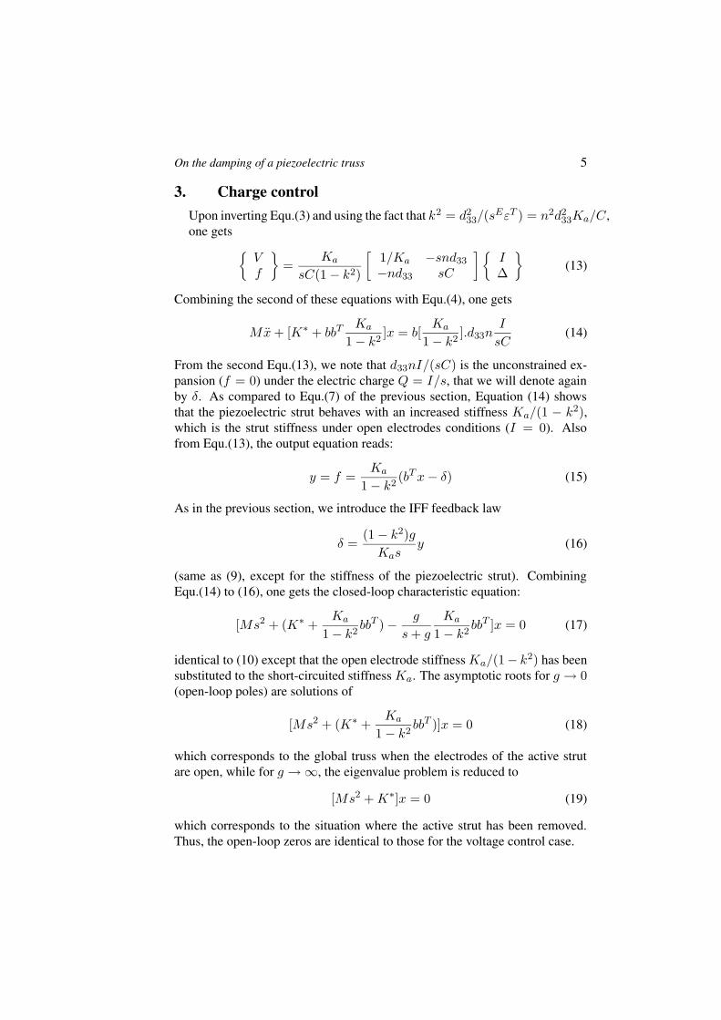
On the damping of a piezoelectric truss 5
3. Charge controlUpon inverting Equ.(3) and using the fact that k2 = d2
33/(sEεT ) = n2d2
33Ka/C,one gets
Vf
=Ka
sC(1− k2)
[
1/Ka −snd33
−nd33 sC
]
I∆
(13)
Combining the second of these equations with Equ.(4), one gets
Mx+ [K∗ + bbTKa
1− k2]x = b[
Ka
1− k2].d33n
I
sC(14)
From the second Equ.(13), we note that d33nI/(sC) is the unconstrained ex-pansion (f = 0) under the electric charge Q = I/s, that we will denote againby δ. As compared to Equ.(7) of the previous section, Equation (14) showsthat the piezoelectric strut behaves with an increased stiffness Ka/(1 − k2),which is the strut stiffness under open electrodes conditions (I = 0). Alsofrom Equ.(13), the output equation reads:
y = f =Ka
1− k2(bTx− δ) (15)
As in the previous section, we introduce the IFF feedback law
δ =(1− k2)g
Kasy (16)
(same as (9), except for the stiffness of the piezoelectric strut). CombiningEqu.(14) to (16), one gets the closed-loop characteristic equation:
[Ms2 + (K∗ +Ka
1− k2bbT )−
g
s+ g
Ka
1− k2bbT ]x = 0 (17)
identical to (10) except that the open electrode stiffness Ka/(1− k2) has beensubstituted to the short-circuited stiffness Ka. The asymptotic roots for g → 0(open-loop poles) are solutions of
[Ms2 + (K∗ +Ka
1− k2bbT )]x = 0 (18)
which corresponds to the global truss when the electrodes of the active strutare open, while for g →∞, the eigenvalue problem is reduced to
[Ms2 +K∗]x = 0 (19)
which corresponds to the situation where the active strut has been removed.Thus, the open-loop zeros are identical to those for the voltage control case.
6
Ip
sCYSH
V
I
sC
I
V
Ip = snd33f
(b)(a)
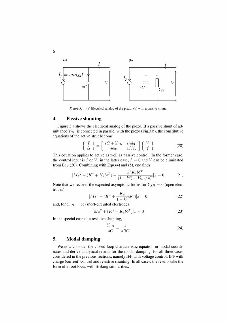
Figure 3. (a) Electrical analog of the piezo. (b) with a passive shunt.
4. Passive shuntingFigure 3.a shows the electrical analog of the piezo. If a passive shunt of ad-
mittance YSH is connected in parallel with the piezo (Fig.3.b), the constitutiveequations of the active strut become
I∆
=
[
sC + YSH snd33
nd33 1/Ka
]
Vf
(20)
This equation applies to active as well as passive control. In the former case,the control input is I or V ; in the latter case, I = 0 and V can be eliminatedfrom Equ.(20). Combining with Equ.(4) and (5), one finds:
[Ms2 + (K∗ +KabbT ) +
k2KabbT
(1− k2) + YSH/sC]x = 0 (21)
Note that we recover the expected asymptotic forms for YSH = 0 (open elec-trodes)
[Ms2 + (K∗ +Ka
1− k2bbT )]x = 0 (22)
and, for YSH =∞ (short-circuited electrodes):
[Ms2 + (K∗ +KabbT )]x = 0 (23)
In the special case of a resistive shunting,
YSH
sC=
1
sRC(24)
5. Modal dampingWe now consider the closed-loop characteristic equation in modal coordi-
nates and derive analytical results for the modal damping, for all three casesconsidered in the previous sections, namely IFF with voltage control, IFF withcharge (current) control and resistive shunting. In all cases, the results take theform of a root locus with striking similarities.

On the damping of a piezoelectric truss 7
5.1 IFF, voltage controlThe development follows closely that of [2]; transforming in modal coor-
dinates according to x = Φz, assuming normal modes normalized accordingto ΦTMΦ = I; the mode shapes are solution of the eigenvalue problem (11).Denoting
ΦT (K∗ +KabbT )Φ = ω2 = diag(ω2
i ) (25)
where ωi are the natural frequencies of the truss with short-circuited electrodes,Equ.(10) is rewritten
[Is2 + ω2 −g
s+ gΦT (Kabb
T )Φ]z = 0 (26)
The matrix ΦT (KabbT )Φ is in general fully populated; assuming that it is
diagonally dominant, and neglecting the off-diagonal terms, it can be rewritten
ΦT (KabbT )Φ ' diag(νiω
2
i ) (27)
where
νi =φT
i(Kabb
T )φi
φTi(K∗ +KabbT )φi
(28)
is the fraction of modal strain energy in the active strut when the truss vi-brates according to mode i. According to the assumption (27), the open-loopfrequency response function (FRF) between the unconstrained expansion δ andthe output force y of the collocated sensor can be written ([2], p.61)
G(ω) =y
δ= Ka[
n∑
i=1
νi
1− ω2/ω2i
− 1] (29)
where the sum extends to all the modes. Thus, the fractions of modal strainenergy νi constitute the residues of the modal expansion of the open-loop FRF(Fig.4). The fact that they are all positive guarantees alternating poles andzeros, as one would expect from a collocated (and dual) actuator/sensor con-figuration.
It follows also from the assumption (27) that the eigenvalue problem (26)reduces to a set of uncoupled equations
s2 + ω2
i −g
s+ gνiω
2
i = 0 (30)
Denotingz2
i = ω2
i (1− νi) (31)
Equ.(30) can be transformed into
1 + gs2 + z2
i
s(s2 + ω2i)= 0 (32)

8
G(!)
z1 z2 z3
!1 !2 !3
P
i=1
n
÷ià 1 P
i=m+1
n
÷ià 1
Poles
Zeros
Figure 4. Open loop FRF G(ω) of the active truss.
which shows that every mode follows a root locus with poles at ±jωi andat s = 0, and zeros at ±jzi (Fig.5). Comparing with Equ.(12), the latter arereadily identified as the natural frequencies of the structure when the axial con-tribution of the active strut has been removed. The maximum modal dampingis given by
ξmaxi =
ωi − zi
2zi
(33)
and it is achieved for g = ωi
√
ωi/zi [2].
5.2 IFF, charge controlIf we consider the charge implementation of the IFF (with a current am-
plifier), the closed-loop characteristic equation is given by Equ.(17). Trans-forming in modal coordinates as in the previous section, but using the normalmodes of the truss with open electrodes, solutions of the eigenvalue problem(18), the natural frequencies and the fraction of modal strain energy are definedrespectively by
ΦT (K∗ +Ka
1− k2bbT )Φ = Ω2 = diag(Ω2
i ) (34)
νi =φT
i( Ka
1−k2 bbT )φi
φTi(K∗ + Ka
1−k2 bbT )φi
(35)

On the damping of a piezoelectric truss 9
IFF
ømaxi =2z i
!iàz i
ømaxi
!i
zi
Figure 5. Root locus of the IFF, voltage control (only half of the locus is shown).
Following the same development as in the previous section, one finds that theclosed-loop poles follow the root locus
1 + gs2 + z2
i
s(s2 +Ω2i)= 0 (36)
which is similar to that of Fig.5, except that the poles at ±jΩi correspond inthis case to the natural frequencies of the truss with open electrodes; the zerosare identical to those of the previous case.
5.3 Resistive shuntingFor resistive shunting, the characteristic equation is given by Equ.(21) with
YSH = 1/R; denoting RC = % and transforming in modal coordinates asin the previous sections, one finds that every mode follow the characteristicequation
s2 + ω2
i +k2νiω
2i
1− k2 + 1/%s= 0 (37)
which can be rewritten in a root locus form
1 +s2 + ω2
i
%(1− k2)s[s2 + ω2i+ k2
1−k2 νiω2i]= 0 (38)
where 1/%(1−k2) plays the role of the gain in a classical root locus. At the de-nominator, one recognizes that the poles are located at the natural frequenciesof the truss with open electrodes
Ω2
i ' ω2
i (1 +k2
1− k2νi) (39)
10
Re(s)
Im(s)
Resistive Shunting
IFF charge control
IFF voltage control
(Actuator withOpen electrodes)
(Actuator with Short-circuited electrodes)
(Actuator removed)
= j!i 1 +1àk2k2÷i
qjÒi
j!i
jzi = j!i 1à ÷ip
Figure 6. Root locus plots corresponding to various control configurations.
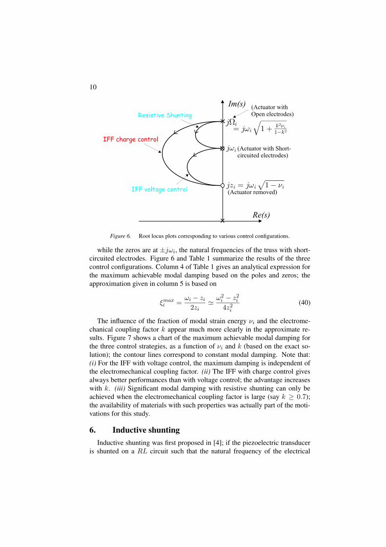
while the zeros are at ±jωi, the natural frequencies of the truss with short-circuited electrodes. Figure 6 and Table 1 summarize the results of the threecontrol configurations. Column 4 of Table 1 gives an analytical expression forthe maximum achievable modal damping based on the poles and zeros; theapproximation given in column 5 is based on
ξmaxi =
ωi − zi
2zi
'ω2
i− z2
i
4z2i
(40)
The influence of the fraction of modal strain energy νi and the electrome-chanical coupling factor k appear much more clearly in the approximate re-sults. Figure 7 shows a chart of the maximum achievable modal damping forthe three control strategies, as a function of νi and k (based on the exact so-lution); the contour lines correspond to constant modal damping. Note that:(i) For the IFF with voltage control, the maximum damping is independent ofthe electromechanical coupling factor. (ii) The IFF with charge control givesalways better performances than with voltage control; the advantage increaseswith k. (iii) Significant modal damping with resistive shunting can only beachieved when the electromechanical coupling factor is large (say k ≥ 0.7);the availability of materials with such properties was actually part of the moti-vations for this study.
6. Inductive shuntingInductive shunting was first proposed in [4]; if the piezoelectric transducer
is shunted on a RL circuit such that the natural frequency of the electrical

On
thedam
pingofa
piezoelectrictruss
11
Table 1. Open-loop poles and zeros and maximum achievable modal damping
Type of Control Open-loop poles Open-loop zeros ξi (exact solution) ξi (approximate)
±jziIFF (voltage control) ±jωi ' ±jωi
√1− νi
√1−νi−(1−νi)
2(1−νi)νi
4(1−νi)
±jΩi
IFF (charge control) ±jωi
√
1 + k2νi
1−k2 ±jzi
√
1+k2νi1−k2−
√1−νi
2√
1−νiνi
4(1−νi)(1−k2)
Resistive shunting ±jΩi ±jωi
√
1+k2νi1−k2−1
2k2νi
4(1−k2)

12
(a)
(c)
(b)
÷i
k
x=0.05
x=0.1
x=0.2
x=0.4
x=0.6
x=0.8x=1.0
k
÷i
x=0.05
x=0.1
x=0.2
x=0.4
x=0.6
x=0.8 x=1.0
Over critical
÷i
k
x=0.05
x=0.005
x=0.01
x=0.02
x=0.1
x=0.2
x=0.4
Figure 7. Maximum achievable modal damping as a function of νi and k. (a) IFF voltagecontrol, (b) IFF charge control, (c) Resistive shunting.

On the damping of a piezoelectric truss 13
circuit is tuned on the natural frequency of one mode, the system behaves likea tuned mass damper [6]. The extension to multiple modes has been addressedin [7], where the use of a set of parallel shunts is suggested; other methods arereviewed in [8]. This section is by no means comprehensive but, once again,the closed-loop poles for inductive shunting are presented in the form of aroot locus where the major structural (νi), material (k), and electrical (ωe/ωi)parameters appear explicitly.
The characteristic equation for an arbitrary passive shunting is given byEqu.(21). Upon transforming in modal coordinates, with the same assump-tions as in the previous section, one finds that the characteristic equation formode i reads:
s2 + ω2
i +k2νiω
2i
1− k2 + YSH/sC= 0 (41)
If the passive shunt consists of a RL circuit, YSH = (Ls+R)−1 and
YSH
sC=
1
LCs2 +RCs(42)
Upon introducing the electrical natural frequency ω2e = (LC)−1 and the frac-
tion of critical damping ξe such that 2ξeωe = R/L, one gets
YSH
sC=
1
s2/ω2e + 2ξes/ωe
(43)
and the characteristic equation (41) becomes
s2 + ω2
i +k2νiω
2i(s2 + 2ξeωes)
(1− k2)(s2 + 2ξeωes) + ω2e
= 0 (44)
This equation can, once again, be rearranged in the form of a root locus
1 + 2ξeωe.s(s2 +Ω2
i)
(s2 + p21)(s2 + p2
2)= 0 (45)
in which 2ξeωe plays the role of the gain. Ωi is the natural frequency withopen electrodes (±jΩi are indeed the asymptotic poles when the resistor Rbecomes very large), and p2
1 and p22 are solutions of the characteristic equation
s4
ω4i
+s2
ω2i
[1 +k2νi
1− k2+ω2
e
ω2i
1
1− k2] +
ω2e
ω2i
1
1− k2= 0 (46)
which, in addition to νi and k, also depends on the tuning ratio ωe/ωi be-tween the electrical circuit and the mechanical vibration. The upper half of theroot locus consists of two loops whose size depends on the values of the pa-rameters; the depth of the smaller loop in the left half plane tends to be biggerwhen the tuning ratio is close to 1.
14
7. ConclusionsVarious active and passive ways of damping a piezoelectric truss have been
examined; the results have been presented in the common form of a root locus,and analytical formulae have been established for the maximum achievablemodal damping. The influence of the modal fraction of strain energy νi in theactive strut (structural parameter) and the electromechanical coupling coeffi-cient k (material parameter) on the performance has been pointed out.
AcknowledgmentsThis study was partly supported by ESA (SSPA project).
References[1] Preumont,A., J.P.Dufour, C.Malekian, Active damping by a local force feedback with
piezoelectric actuators, AIAA J. of Guidance, vol.15, No 2, 390-395, March-April, 1992.
[2] Preumont,A. Vibration Control of Active Structures, An Introduction, (2nd Edition),Kluwer, 2002.
[3] D-orlemann,C., P.Muss, M.Schugt, R.Uhlenbrock, New high speed current controlled am-plifier for PZT multilayer stack actuators, ACTUATOR-2002, Bremen, June, 2002.
[4] Forward,R.L., Electronic damping of vibrations in optical structures, Journal of AppliedOptics, 18, 690-697, March, 1979.
[5] Hagood,N.W., A.von Flotow, Damping of structural vibrations with piezoelectric materialsand passive electrical networks, Journal of Sound and Vibration 146(2), 243-268, 1991.
[6] Hagood,N.W., E.F.Crawley, Experimental investigation of passive enhancement of damp-ing for space structures,AIAA J. of Guidance, vol.14, No 6, 1100-1109, Nov.Dec. 1991.
[7] Hollkamp,J.J., Multimodal passive vibration suppression with piezoelectric materials andresonant shunts, J. Intell. Material Syst. Structures, Vol.5, Jan.1994.
[8] Moheimani,S.O.R., A survey of recent innovations in vibration damping and control us-ing shunted piezoelectric transducers, IEEE Transactions on Control Systems Technology,Vol.11, No 4, 482-494, July 2003.