Embed Size (px)
Citation preview
On the cloaking effects associated withanomalous localized resonance
BY GRAEME W. MILTON1,* AND NICOLAE-ALEXANDRU P. NICOROVICI
2
1Department of Mathematics, University of Utah, Salt Lake City,Utah 84112, USA
2Department of Mathematical Sciences, University of Technology,Sydney NSW 2007, Australia
Regions of anomalous localized resonance, such as occurring near superlenses, areshown to lead to cloaking effects. This occurs when the resonant field generated by apolarizable line or point dipole acts back on the polarizable line or point dipole andeffectively cancels the field acting on it from outside sources. Cloaking is proved in thequasistatic limit for finite collections of polarizable line dipoles that all lie within aspecific distance from a coated cylinder having a shell permittivity 3szK3mzK3c where3m is the permittivity of the surrounding matrix, and 3c is the core permittivity.Cloaking is also shown to extend to the Veselago superlens outside the quasistaticregime: a polarizable line dipole located less than a distance d/2 from the lens, where dis the thickness of the lens, will be cloaked due to the presence of a resonant field infront of the lens. Also a polarizable point dipole near a slab lens will be cloaked in thequasistatic limit.
Keywords: cloaking; localized resonance; superlenses; negative refraction
*A
RecAcc
1. Introduction
Nicorovici et al. (1994) found that a coated cylinder, now called a cylindricalsuperlens, with a core of dielectric constant 3cZ1 and radius rc and a shell withdielectric constant 3sZK1C i300s and outer radius rs would in the limit 300s /0 beinvisible to any applied quasistatic transverse magnetic (TM) field. Here we showthat not only is the lens invisible in this limit, but so too are cylindrical objects,or at least any finite collection of polarizable line dipoles, that lie within a radiusr#h
ffiffiffiffiffiffiffiffiffiffiffir3s =rc
pof the cylindrical superlens.
In that paper some other remarkable properties were found to hold in the limit300s /0. First a cylinder of radius rc and permittivity 3cs1 placed inside thecylindrical shell would to an outside observer appear magnified by a factor ofhZr2s =r
2c and respond like a solid cylinder of permittivity 3c of radius r�ZrchZ
r2s =rc to any quasistatic TM applied fields that do not have sources within theradius r�. Second, again when 3cs1, a dipole line source positioned outside thecoated cylinder at a radius r0 less than rcritZr3s =r
2c Zr2�=rs would have an image
Proc. R. Soc. A
doi:10.1098/rspa.2006.1715
Published online
uthor for correspondence ([email protected]).
eived 16 December 2005epted 16 March 2006 1 q 2006 The Royal Society
G. W. Milton and N.-A. P. Nicorovici2
dipole line source (ghost source) lying outside the cylinder at the radius~r0Zr2�=r0Ors. Specifically, because there cannot be singularities in the fieldoutside the cylinder, apart from the original line dipole source, at radii greaterthan ~r0 the image dipole was found to appear to be like an actual line source withthe approximation becoming better as 300s /0 but inside the radius ~r0 numericalcomputations showed that the field had enormous oscillations, which grew as300s /0.
A mathematically very similar phenomena was implied by the bold claim ofPendry (2000) (see also the reviews of Pendry (2004) and Ramakrishna (2005))that the Veselago slab lens (Veselago 1968), consisting of a slab of materialhaving thickness d, relative electric permittivity 3sZK1, relative magneticpermeability msZK1, would act as a superlens: a line (or point) dipole sourcelocated at distance d0 in front of the Veselago lens would when d0!d, have aline image dipole source (ghost source) lying outside the lens at a distancedKd0 from the back of the lens. Again there cannot be singularities in the fieldlying outside the lens apart from the original line, or point, dipole source asemphasized by Maystre & Enoch (2004) among others. For the losslessVeselago lens Garcia & Nieto-Vesperinas (2002) and Pokrovsky & Efros (2002)claimed the fields lost their square integrability throughout a layer of thickness2ðdKd0Þ centered on the back interface, although it is not clear to us whetherthe claimed divergence within the entire layer in the lossless case is an artifactof the use of plane wave expansions, in the same way that Taylor series divergeoutside the radius of convergence, but other expansions have different regionsof convergence. One should allow for some small loss, taking 3sZK1C i300s ,msZK1C im00
s and consider what happens when 300s and m00s are very small. At
distances greater than dKd0 from the back of the lens the image sourceappears to be like an actual line (or point) source with the approximationbecoming better as ð300s ;m00
s Þ/0 but at distances less than dKd0 from the backof the lens the field has enormous oscillations, which grow as ð300s ;m00
s Þ/0.Contrary to the conventional picture, the field also has enormous oscillations infront of the lens as shown by Podolskiy et al. (2005) and these fields are theones responsible for cloaking (see also Rao & Ong (2003), Shvets (2003),Merlin (2004) and Guenneau et al. (2005)) whose investigations provided someevidence of large fields in front of the lens). We will see here that in fact thefield generated by a constant amplitude line dipole source diverges as 300s ;m
00s /0
within a distance of dKd0 from either the front or back interface. Thisgeneralizes the result of Milton et al. (2005) where the same regions of fielddivergence were found for the quasistatic equations. As that paper will befrequently referenced, it will be denoted by the acronym MNMP. We will findthat a polarizable line dipole less than a distance d=2 from the Veselago lensbecomes cloaked in the limit as ð300s ;m00
s Þ/0. Furthermore we will see that, in thequasistatic limit, a polarizable point dipole outside a slab having electricpermittivity 3sZK1C i300s , and any magnetic permeability, becomes cloaked as300s /0.
Following Milton (2002), §11.7, and MNMP we say an inhomogeneous bodyexhibits anomalous localized resonance if as the loss goes to zero (or for staticproblems, as the system of equations lose ellipticity) the field magnitudediverges to infinity throughout a specific region with sharp boundaries notdefined by any discontinuities in the moduli, but the field converges to a smooth
Proc. R. Soc. A
3Cloaking effects associated with resonance
field outside that region. A region where the field diverges will be called a regionof local resonance. We will see that cloaking occurs when a polarizable line orpoint dipole interacts with the resonant field that is generated by thepolarizable line or point dipole itself, and that the effect of the resonant regionis to cancel the field acting on the polarizable line or point dipole from outsidesources. A region where a polarizable line or point dipole is cloaked will becalled a cloaking region.
Cloaking can also be regarded as a consequence of energy considerations: ifthe polarizable line or point dipole was not cloaked then the energy sources inthe system would have to be infinite. As shown in the paper MNMP, and asstemmed from a suggestion of Alexei Efros (2005, personal communication), aline dipole source with a fixed dipole moment less than a distance d=2 from theslab lens would could cause infinite energy loss. (We will see this is true not justfor the quasistatic solution, but also for the solution to Maxwell’s equations forthe Veselago lens.) Any realistic dipole source (such as a polarizable line source)within this region must have a dipole moment which vanishes as 300s /0. Asthe lens provides a perfect image of the source in the limit 300s /0, at leastfurther than a distance d from the slab, we conclude that the dipole sourcewill have a vanishingly small effect on the field further than a distance d fromthe slab.
We remark that the cloaking effects discussed here extend to staticmagnetoelectric equations, as implied by the equivalence discussed in §6 ofMNMP that follows from earlier work of Cherkaev & Gibiansky (1994) andMilton (2002), §11.6. There it is shown that the two-dimensional quasistaticdielectric equations in any geometry (and with possible source terms) can betransformed to a set of magnetoelectric equations (with corresponding sourceterms) with a symmetric real positive definite tensor entering the constitutivelaw. Therefore properties like superlensing and cloaking which hold for thequasistatic dielectric equations automatically also hold for the equivalentmagnetoelectric equations.
2. Some simple examples of cloaking in the quasistatic limit
First we present an example which shows that a polarizable line withpolarizability a (and possibly a source term) can be cloaked when immersed ina TM field surrounding a coated cylinder with inner radius rc, outer radius rs,and with cylinder axis xZyZ0. The polarizable line is placed along xZr0 andyZ0, where r0Ors. Suppose ðExðx; yÞ;Eyðx; yÞ; 0Þ is the field without thepolarizable line present due to:
(i) Fields generated by fixed sources not varying in the Z direction lyingoutside the radius r� hr2s =rc when 3cs3m, and the radius r#h
ffiffiffiffiffiffiffiffiffiffiffir3s =rc
pwhen 3cZ3m. (Here we use Z for the z-coordinate to avoid confusion withzZxC iy). We assume these sources are not perturbed when thepolarizable line is introduced.
(ii) Fields generated by the coated cylinder due to its interaction with thesefixed sources.
Proc. R. Soc. A
G. W. Milton and N.-A. P. Nicorovici4
Let 3m, 3s, and 3c denote the permittivity in the matrix, shell and core, and letus set
hZ3mK3c
3m C3c;
ð3s C3cÞð3m C3sÞð3sK3cÞð3mK3sÞ
Z deif; ð2:1Þ
where d is real and positive. We assume that 3c and 3m remain fixed with 3m realand positive, and with 3c possibly complex (with non-negative imaginary part)but not real and negative, and that 3s approachesK3m along a trajectory in theupper half of the complex plane in such a way that d/0 but f remains fixed.
When 3s is close toK3m equation (2.1) implies
3szðK1C2deif=hÞ3m when 3cs3m;
zðK1C2iffiffiffid
peif=2Þ3m when 3c Z 3m;
)ð2:2Þ
and so we have
dzj3sC3mjjhj=ð23mÞ when 3cs3m;
zj3sC3mj2=ð432mÞ when 3c Z 3m:
)ð2:3Þ
Thus, for small d the trajectory approachesK3m in such a way that the argumentof 3sC3m is approximately constant.
Let us drop the Z field component of the electric field since it is zero for TMfields. The field ðE0
x ;E0y Þ acting on the polarizable line has two components:
ðE0x ;E
0y ÞZ ðEx CEr
x ;Ey CEry Þ; ð2:4Þ
where
Ex hExðr0; 0Þ; Ey hEyðr0; 0Þ; Erx hEr
x ðr0; 0Þ; Ery hEr
y ðr0; 0Þ;ðEr
x ðx; yÞ;Ery ðx; yÞÞZ ðKvVinðx; yÞ=vx;KvVinðx; yÞ=vyÞ;
)ð2:5Þ
and Vinðx; yÞ is the (possibly resonant) response potential in the matrixgenerated by the coated cylinder responding to the polarizable line itself (notincluding the field generated by the coated cylinder responding to the other fixedsources). The field ðEr
x ;Ery Þ must depend linearly on the dipole moment of the
polarizable line, and in fact, as we will see shortly, this dependence has the form
Erx
Ery
!Z cðdÞ
ke
Kko
!; ð2:6Þ
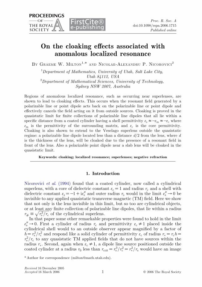
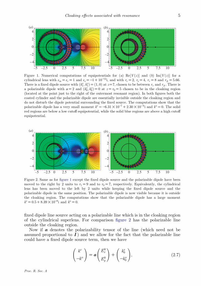
in which, following the notation of MNMP, ke and ko are the (suitablynormalized) dipole moments of the polarizable line (ke gives the amplitude of thedipole component which has even symmetry about the x-axis while ko gives theamplitude of the dipole component which has odd symmetry about the x-axis).We will see that jcðdÞj can diverge to infinity as d/0, and that when thishappens the polarizable line becomes cloaked. Figure 1 shows the cloaking with a
Proc. R. Soc. A
–5 –2.5 0 2.5 5 7.5 10
–4
–2
0
2
4
–5 –2.5 0 2.5 5 7.5 10
–4
–2
0
2
4(a) (b)
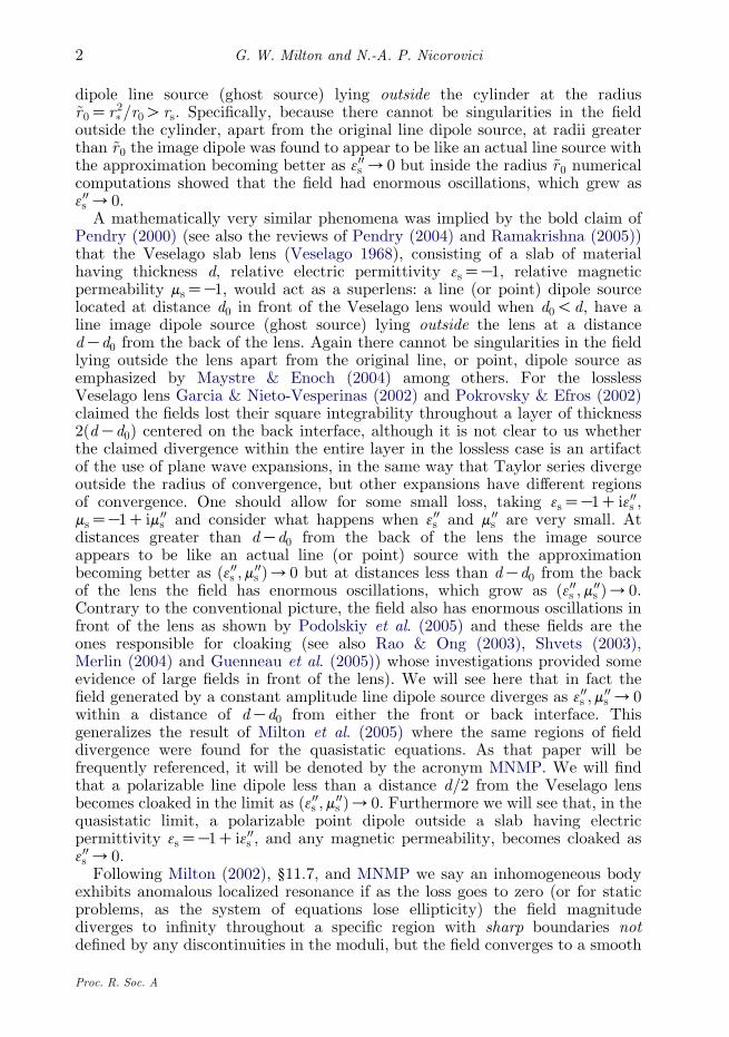
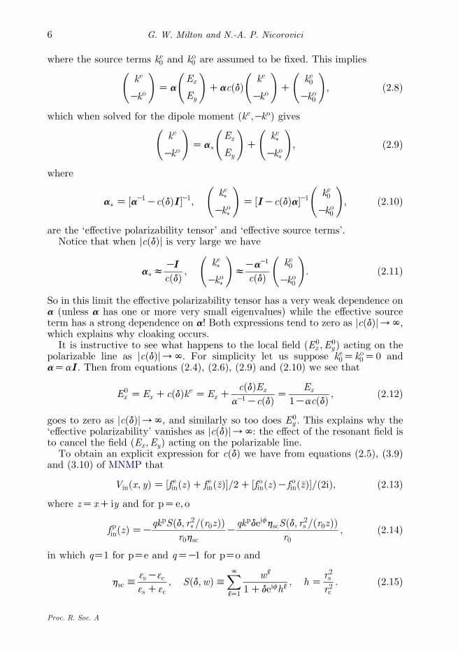
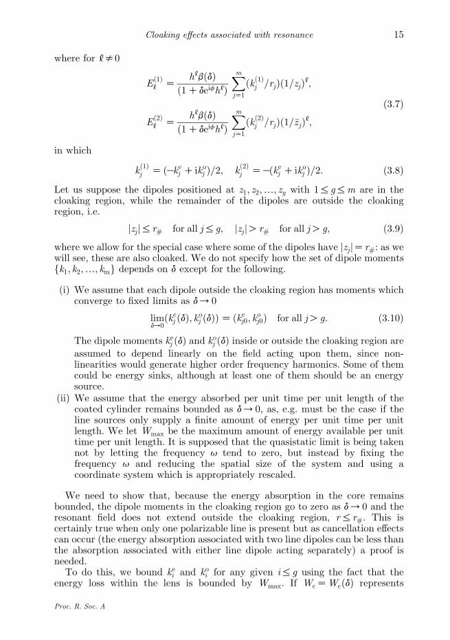
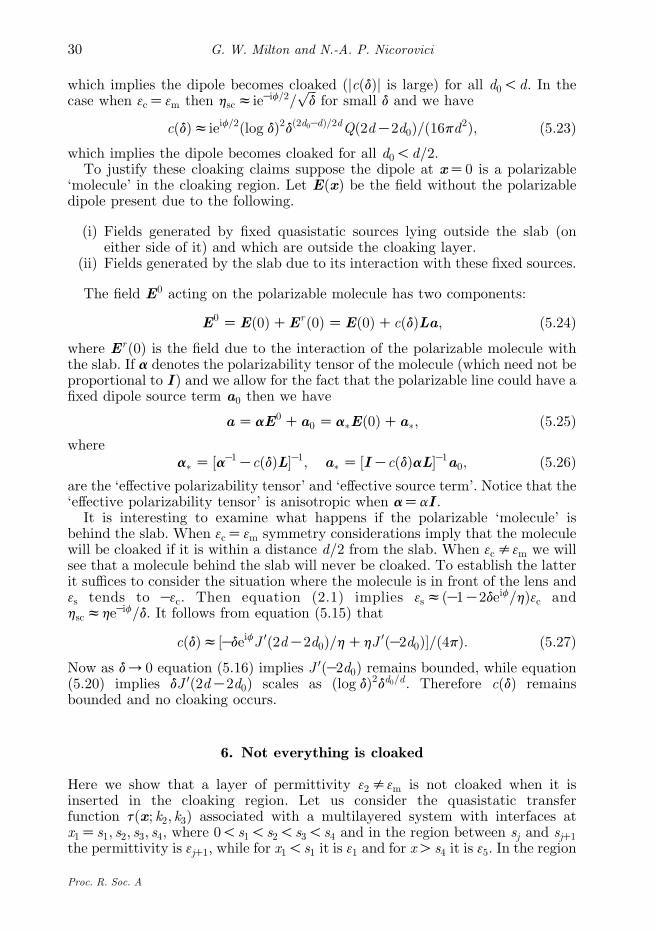
Figure 2. Same as for figure 1 except the fixed dipole source and the polarizable dipole have beenmoved to the right by 2 units to r1Z9 and to r0Z7, respectively. Equivalently, the cylindricallens has been moved to the left by 2 units while keeping the fixed dipole source and thepolarizable dipole in the same position. The polarizable dipole is now visible because it is outsidethe cloaking region. The computations show that the polarizable dipole has a large momentkeZ0:5C8:39!10K8i and koZ0.
–5 –2.5 0 2.5 5 7.5 10
–4
–2
0
2
4
–5 –2.5 0 2.5 5 7.5 10
–4
–2
0
2
4(a) (b)
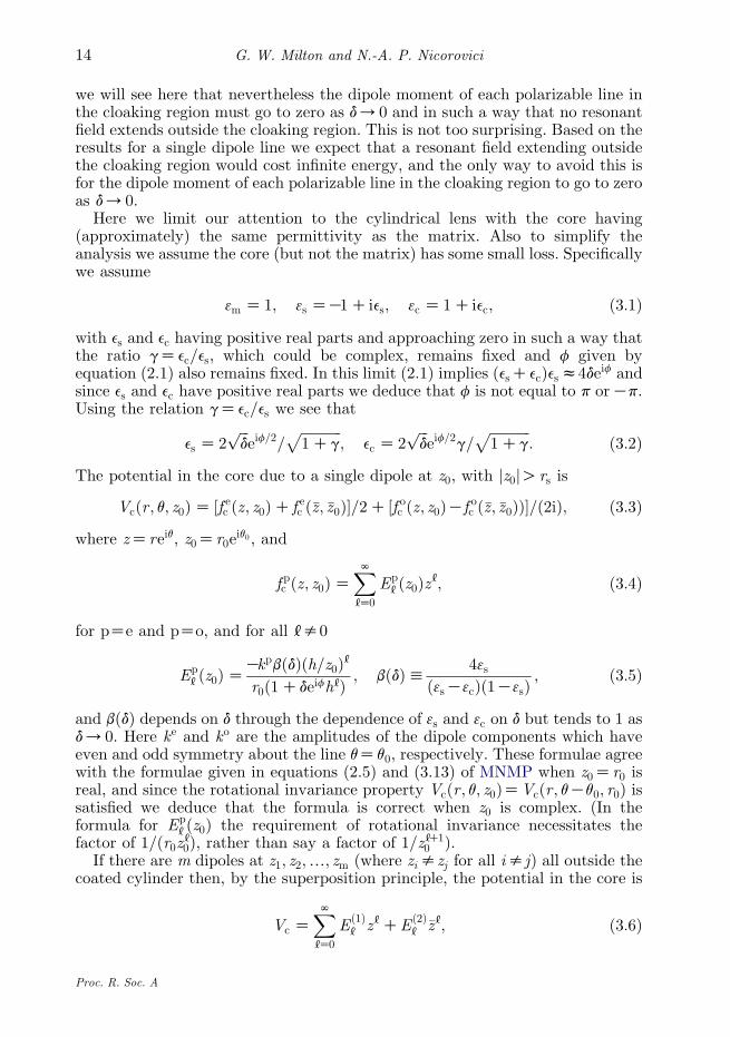
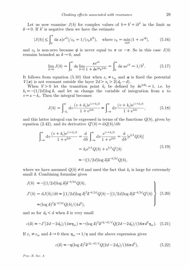
Figure 1. Numerical computations of equipotentials for (a) Re½V ðzÞ� and (b) Im½V ðzÞ� for acylindrical lens with 3mZ3cZ1 and 3sZK1C10K12i, and with rcZ2, rsZ4, r�Z8 and r#Z5:66.There is a fixed dipole source with ðke1; ko1ÞZð1; 0Þ at zZ7, chosen to be between r� and r#. There isa polarizable dipole with aZ2 and ðke0; ko0ÞZ0 at zZr0Z5 chosen to be in the cloaking region(located at the point just to the right of the outermost resonant region). In both figures both thecoated cylinder and the polarizable dipole are essentially invisible outside the cloaking region anddo not disturb the dipole potential surrounding the fixed source. The computations show that thepolarizable dipole has a very small moment keZK6:31!10K7C2:30!10K6i and koZ0. The solidred regions are below a low cutoff equipotential, while the solid blue regions are above a high cutoffequipotential.
5Cloaking effects associated with resonance
fixed dipole line source acting on a polarizable line which is in the cloaking regionof the cylindrical superlens. For comparison figure 2 has the polarizable lineoutside the cloaking region.
Now if a denotes the polarizability tensor of the line (which need not beassumed proportional to I ) and we allow for the fact that the polarizable linecould have a fixed dipole source term, then we have
ke
Kko
!Za
E0x
E0y
!C
ke0
Kko0
!; ð2:7Þ
Proc. R. Soc. A
G. W. Milton and N.-A. P. Nicorovici6
where the source terms ke0 and ko0 are assumed to be fixed. This implies
ke
Kko
!Za
Ex
Ey
!CacðdÞ
ke
Kko
!C
ke0
Kko0
!; ð2:8Þ
which when solved for the dipole moment ðke;KkoÞ gives
ke
Kko
!Za�
Ex
Ey
!C
ke�
Kko�
!; ð2:9Þ
where
a� Z ½aK1KcðdÞI �K1;ke�
Kko�
!Z ½IKcðdÞa�K1
ke0
Kko0
!; ð2:10Þ
are the ‘effective polarizability tensor’ and ‘effective source terms’.Notice that when jcðdÞj is very large we have
a�zKI
cðdÞ ;ke�
Kko�
!zKaK1
cðdÞke0
Kko0
!: ð2:11Þ
So in this limit the effective polarizability tensor has a very weak dependence ona (unless a has one or more very small eigenvalues) while the effective sourceterm has a strong dependence on a! Both expressions tend to zero as jcðdÞj/N,which explains why cloaking occurs.
It is instructive to see what happens to the local field ðE0x ;E
0y Þ acting on the
polarizable line as jcðdÞj/N. For simplicity let us suppose ke0Zko0Z0 andaZaI . Then from equations (2.4), (2.6), (2.9) and (2.10) we see that
E0x ZEx CcðdÞke ZEx C
cðdÞEx
aK1KcðdÞ ZEx
1KacðdÞ ; ð2:12Þ
goes to zero as jcðdÞj/N, and similarly so too does E0y . This explains why the
‘effective polarizability’ vanishes as jcðdÞj/N: the effect of the resonant field isto cancel the field ðEx ;EyÞ acting on the polarizable line.
To obtain an explicit expression for cðdÞ we have from equations (2.5), (3.9)and (3.10) of MNMP that
Vinðx; yÞZ ½f einðzÞC f einð�zÞ�=2C ½f oinðzÞKf oinð�zÞ�=ð2iÞ; ð2:13Þ
where zZxC iy and for pZe; o
f pinðzÞZKqkpSðd; r2�=ðr0zÞÞ
r0hscK
qkpdeifhscSðd; r2s =ðr0zÞÞr0
; ð2:14Þ
in which qZ1 for pZe and qZK1 for pZo and
hsch3sK3c
3s C3c; Sðd;wÞh
XN[Z1
w[
1Cdeifh[; h Z
r2sr2c
: ð2:15Þ
Proc. R. Soc. A
–4 –2 0 2 4 6 8
–4
–2
0
2
4
–4 –2 0 2 4 6 8
–4
–2
0
2
4
(a) (b)
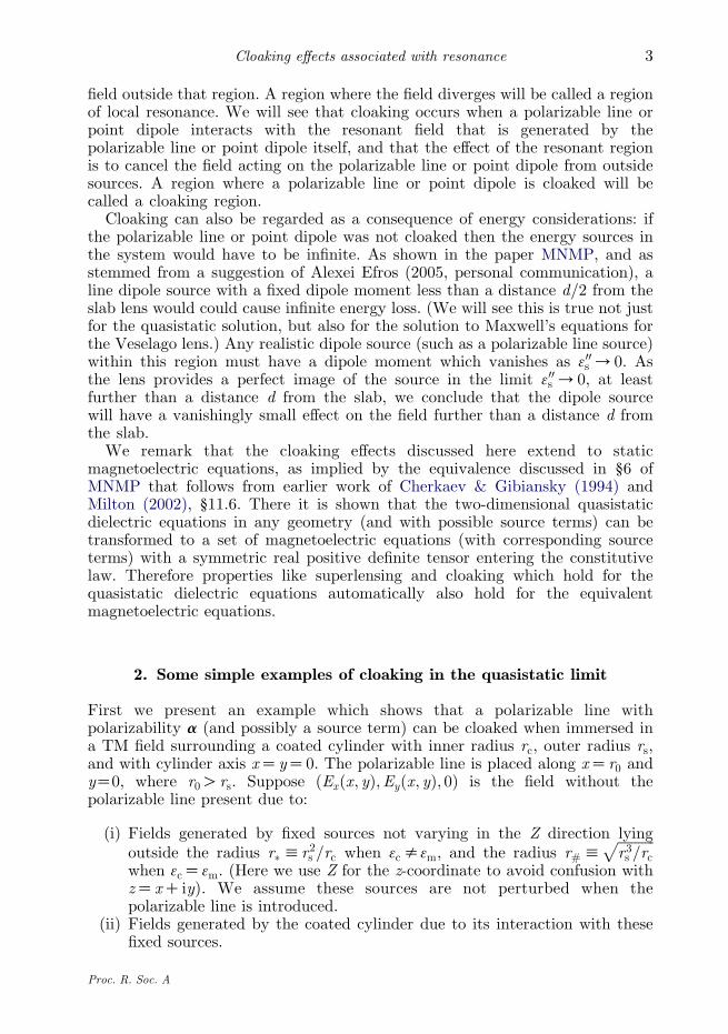
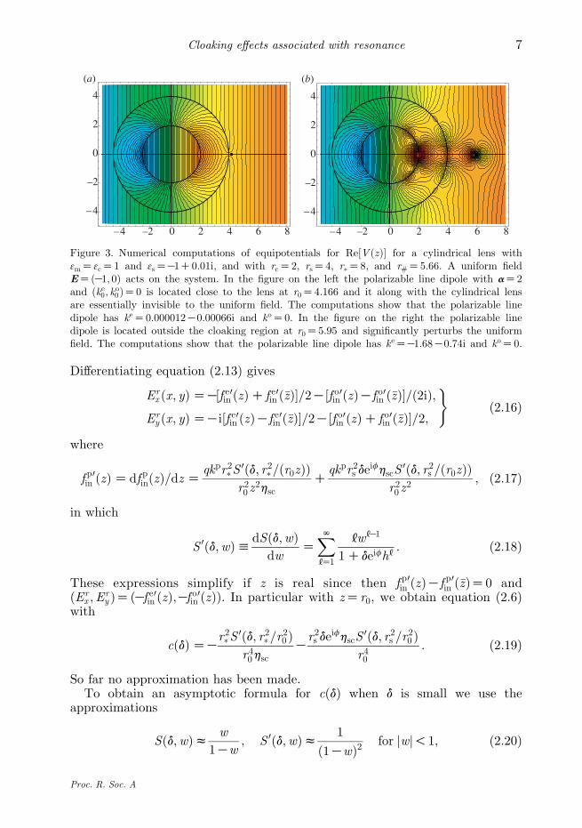
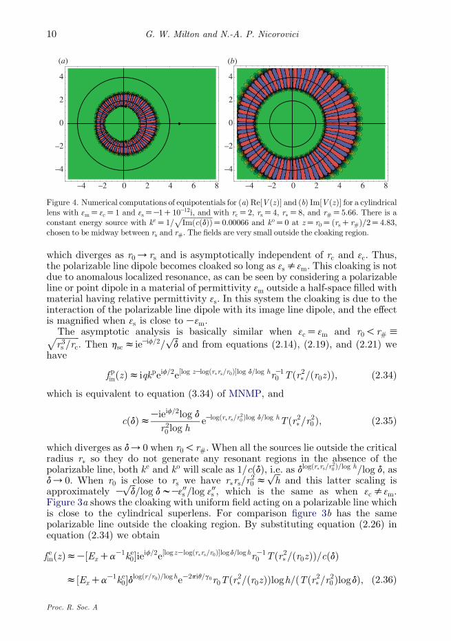
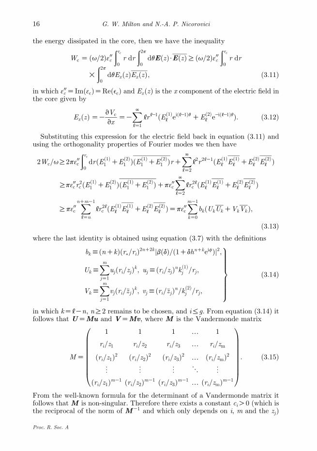
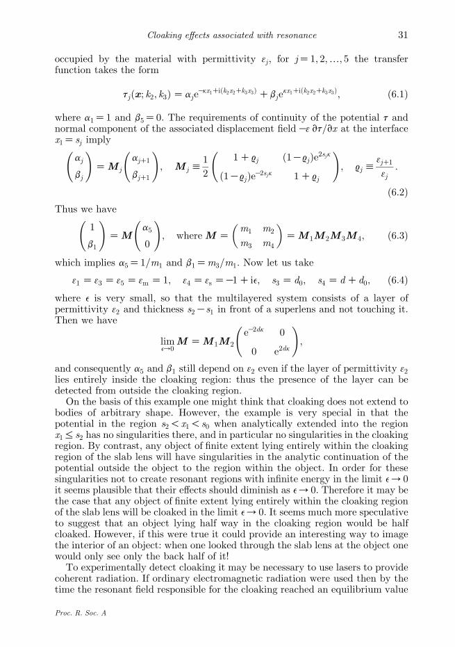
Figure 3. Numerical computations of equipotentials for Re½V ðzÞ� for a cylindrical lens with3mZ3cZ1 and 3sZK1C0:01i, and with rcZ2, rsZ4, r�Z8, and r#Z5:66. A uniform fieldEZðK1; 0Þ acts on the system. In the figure on the left the polarizable line dipole with aZ2and ðke0; ko0ÞZ0 is located close to the lens at r0Z4:166 and it along with the cylindrical lensare essentially invisible to the uniform field. The computations show that the polarizable linedipole has keZ0:000012K0:00066i and koZ0. In the figure on the right the polarizable linedipole is located outside the cloaking region at r0Z5:95 and significantly perturbs the uniformfield. The computations show that the polarizable line dipole has keZK1:68K0:74i and koZ0.
7Cloaking effects associated with resonance
Differentiating equation (2.13) gives
Erx ðx; yÞZK½f e0in ðzÞC f e0in ð�zÞ�=2K½f o0in ðzÞKf o0in ð�zÞ�=ð2iÞ;
Ery ðx; yÞZKi½f e0in ðzÞKf e0in ð�zÞ�=2K½f o0in ðzÞC f o0in ð�zÞ�=2;
)ð2:16Þ
where
f p0in ðzÞZdf pinðzÞ=dz Zqkpr2�S
0ðd; r2�=ðr0zÞÞr20 z
2hscC
qkpr2s deifhscS
0ðd; r2s =ðr0zÞÞr20 z
2; ð2:17Þ
in which
S 0ðd;wÞhdSðd;wÞdw
ZXN[Z1
[w[K1
1Cdeifh[: ð2:18Þ
These expressions simplify if z is real since then f p0in ðzÞKf p0in ð�zÞZ0 andðEr
x ;Ery ÞZðKf e0in ðzÞ;Kf o0in ðzÞÞ. In particular with zZr0, we obtain equation (2.6)
with
cðdÞZKr2�S
0ðd; r2�=r20 Þr40hsc
Kr2s de
ifhscS0ðd; r2s =r20 Þ
r40: ð2:19Þ
So far no approximation has been made.To obtain an asymptotic formula for cðdÞ when d is small we use the
approximations
Sðd;wÞz w
1Kw; S 0ðd;wÞz 1
ð1KwÞ2for jwj!1; ð2:20Þ
Proc. R. Soc. A
G. W. Milton and N.-A. P. Nicorovici8
implied by lemma 3.1 of MNMP, and the approximations
Sðd;wÞzeKlog w log d=log hTðwÞ;
S 0ðd;wÞzK½log d=ðw log hÞ�eKlog w log d=log hTðwÞCeKlog w log d=log hT 0ðwÞzK½log d=ðw log hÞ�eKlog w log d=log hTðwÞ;
9>=>;ð2:21Þ
which hold for hO jwjO1 and are implied by equation (3.22) of MNMP, where
TðwÞZXNjZKN
w j
1Ceifhj; T 0ðwÞZ
XNjZKN
jw jK1
1Ceifhj; ð2:22Þ
and in making the last approximation in equation (2.21) we have assumed that dis so small that jlog dj is very large. (It should be stressed that although we areassuming extremely small loss here, the polarizable line dipole can still becloaked at moderate loss: see figure 3.) Let us first treat the case where 3c is fixedand not equal to 3m and r0!r�. Then we have hscz1=h and substituting theseapproximations in equations (2.14) and (2.19) and keeping only the terms whichare dominant because d is very small gives, for r2�=r0O jzjOrs,
f pinðzÞzKqkphe½log zKlogðr2�=r0Þ�log d=log hrK10 Tðr2�=ðr0zÞÞ; ð2:23Þ
which is equivalent to equation (3.33) of MNMP, and implies
f p0in ðzÞzKqkph log d
zr0 log heKlogðr2�=ðzr0Þlog d=log hTðr2�=ðr0zÞÞ; ð2:24Þ
and
cðdÞz h log d
r20 log heK2 logðr�=r0Þlog d=log hTðr2�=r20 Þ: ð2:25Þ
We see that jcðdÞj/N as d/0 when r0!r�. Consequently both the ‘effectivepolarizability tensor’ and the ‘effective source terms’ approach zero in the limitd/0. For simplicity let us suppose aZaI . Then when d is very small fromequations (2.9) and (2.11) we have
kez½KExKaK1ke0�=cðdÞ; koz½EyKaK1ko0 �=cðdÞ: ð2:26Þ
Thus, the resonant potential associated with the polarizable line has, fromequation (2.23),
f einz½Ex CaK1ke0�he½log zKlogðr2�=r0Þ�log d=log hrK10 Tðr2�=ðr0zÞÞ=cðdÞ
z½Ex CaK1ke0�dlogðr=r0Þ=log heK2piq=g0r0Tðr2�=ðr0zÞÞlog h=ðTðr2�=r20 Þlog dÞ;ð2:27Þ
where g0ZK2p log h=log d is the angular distance between peaks in the resonantpotential and zZreiq. Similarly we have
f oinz½EyKaK1ko0 �dlogðr=r0Þ=log heK2piq=g0r0Tðr2�=ðr0zÞÞlog h=ðTðr2�=r20 Þlog dÞ: ð2:28Þ
Thus as d/0 these resonant potentials in the matrix converge to zero in theregion rOr0 but diverge to infinity with increasingly rapid angular oscillations
Proc. R. Soc. A
9Cloaking effects associated with resonance
for rs%r!r0. (This is to be contrasted with the resonant potential in the matrixassociated with a line dipole having fixed ke and ko, which as can be seen fromequation (2.23) diverges to infinity in the much larger region rs%r!r2�=r0.)A simple calculation, based on substituting the formulae (2.26) and (2.25) intothe formula (3.35) and (3.37) in MNMP for the resonant potentials in the shelland core, shows that the field associated with the polarizable line is resonant inthe entire annulus r2s =r0%r!r0, and converges to zero outside this annulus.
Suppose the source outside is a line dipole with a fixed source term ðke1; ko1ÞZðke1; 0Þ located at the point ðr1; 0Þ, where r1Or�Or0. When r1 is chosen withr2�=r0Or1Or� the polarizable line will be located within the resonant regiongenerated by the line source outside. One might at first think that a polarizableline placed within the resonant region would have a huge response because of theenormous fields there. However, we will see that the opposite is true: the dipolemoment of the polarizable line still goes to zero as d/0. From equations (2.6),(2.16) and (2.24), with r0 replaced by r1, the field at the point ðr0; 0Þ when thepolarizable line is absent will be
Ex Z c1ðdÞke1; Eyðx; yÞZ 0; ð2:29Þ
where
c1ðdÞzh log d
r0r1 log heKlogðr2� =ðr0r1ÞÞlog d=log hTðr2�=ðr0r1ÞÞ: ð2:30Þ
This and equation (2.26) implies the polarizable line has a dipole moment
kezK½Ex CaK1ke0�=cðdÞzKc1ðdÞke1=cðdÞ
zKr0Tðr2�=ðr0r1ÞÞr1Tðr2�=r20 Þ
dlogðr1=r0Þ=log hke1: ð2:31Þ
So ke scales as dlogðr1=r0Þ=log h, which goes to zero as d/0 but fairly slowly when r1and r0 are both close to r�. If the source or sources, are outside the critical radiusrcritZr3s =r
2c then there are no resonant regions associated with these sources and
both ke and ko will scale like 1=cðdÞ, i.e. asKd2 logðr�=r0Þ=log h=log d, which goes tozero at a faster rate as d/0, but still slowly when r0 is close to r�. On the other
hand when r0 is close to rs we have r�=r0zffiffiffih
pand this latter scaling is
approximatelyKd=log dwK300s =log 300s which is quite fast.
Let us examine more closely what happens when r0 approaches rs whilekeeping d fixed (here d is not necessarily small). Then r2�=r
20 is close to h and the
series S 0ðd; r2�=r20 Þ is close to diverging for any fixed d. When zZw=h is close to 1then equation (2.18) implies
S 0ðd;wÞz 1
deifh
XN[Z1
[z[K1 Z1
deifh
d
dz
XN[Z1
z[ Zhscð3mK3sÞ
ð3m C3sÞð1KzÞ2h; ð2:32Þ
and as a result from equation (2.19) we have
cðdÞzKr2�S
0ðd; r2�=r20 Þr40hsc
zKr2s ð3mK3sÞ
ð3mC3sÞðr20Kr2s Þ2z
Kð3mK3sÞ4ð3mC3sÞðr0KrsÞ2
; ð2:33Þ
Proc. R. Soc. A
–4 –2 0 2 4 6 8
–4
–2
0
2
4
(a) (b)
–4 –2 0 2 4 6 8
–4
–2
0
2
4
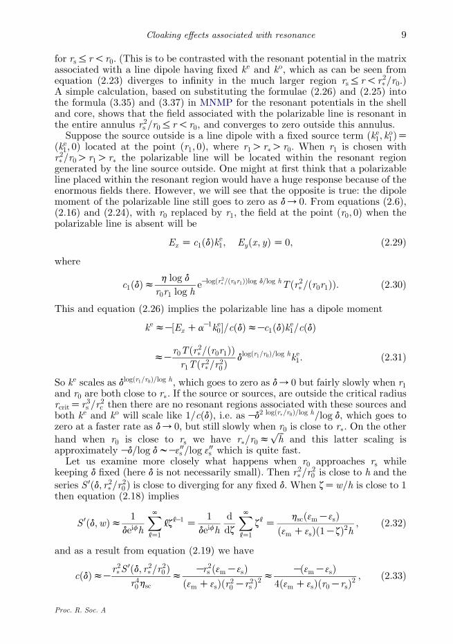
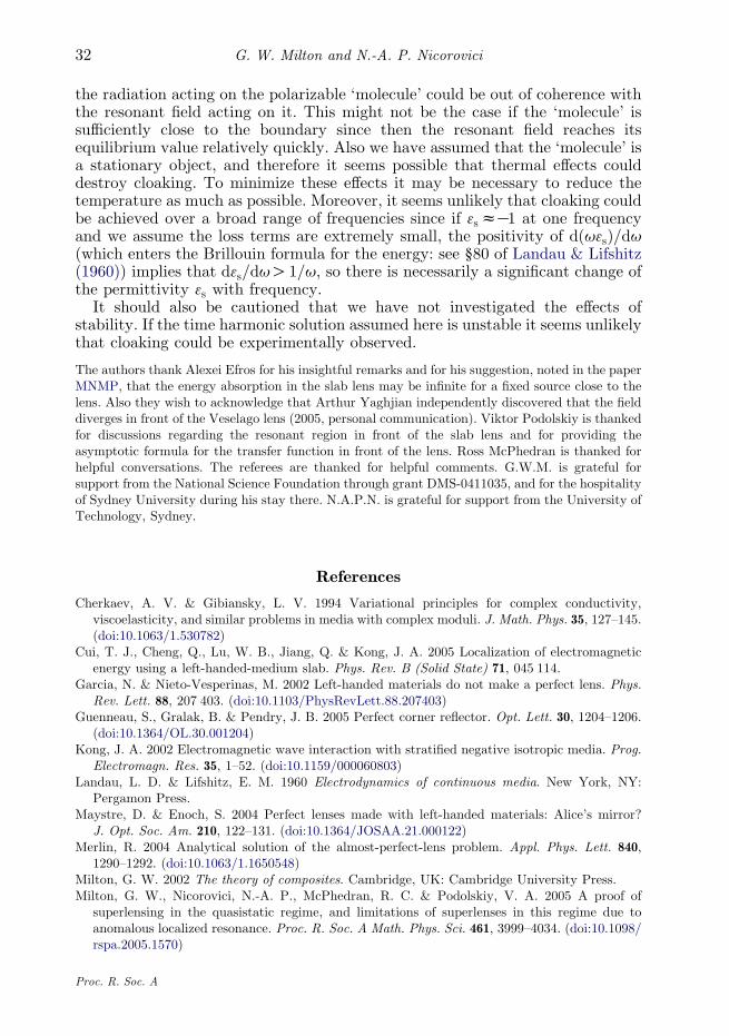
Figure 4. Numerical computations of equipotentials for (a) Re½V ðzÞ� and (b) Im½V ðzÞ� for a cylindricallens with 3mZ3cZ1 and 3sZK1C10K12i, and with rcZ2, rsZ4, r�Z8, and r#Z5:66. There is aconstant energy source with keZ1=
ffiffiffiffiffiffiffiffiffiffiffiffiffiffiffiffiffiffiImðcðdÞÞ
pZ0:00066 and koZ0 at zZr0ZðrsCr#Þ=2Z4:83,
chosen to be midway between rs and r#. The fields are very small outside the cloaking region.
G. W. Milton and N.-A. P. Nicorovici10
which diverges as r0/rs and is asymptotically independent of rc and 3c. Thus,the polarizable line dipole becomes cloaked so long as 3ss3m. This cloaking is notdue to anomalous localized resonance, as can be seen by considering a polarizableline or point dipole in a material of permittivity 3m outside a half-space filled withmaterial having relative permittivity 3s. In this system the cloaking is due to theinteraction of the polarizable line dipole with its image line dipole, and the effectis magnified when 3s is close toK3m.
The asymptotic analysis is basically similar when 3cZ3m and r0!r#hffiffiffiffiffiffiffiffiffiffiffir3s =rc
p. Then hsczieKif=2=
ffiffiffid
pand from equations (2.14), (2.19), and (2.21) we
have
f pinðzÞziqkpeif=2e½log zKlogðr�rs=r0Þ�log d=log hrK10 Tðr2�=ðr0zÞÞ; ð2:34Þ
which is equivalent to equation (3.34) of MNMP, and
cðdÞzKieif=2log d
r20 log heKlogðr�rs=r20 Þlog d=log hTðr2�=r20 Þ; ð2:35Þ
which diverges as d/0 when r0!r#. When all the sources lie outside the criticalradius r� so they do not generate any resonant regions in the absence of thepolarizable line, both ke and ko will scale as 1=cðdÞ, i.e. as dlogðr�rs=r20 Þ=log h=log d, asd/0. When r0 is close to rs we have r�rs=r
20 z
ffiffiffih
pand this latter scaling is
approximately Kffiffiffid
p=log dwK300s =log 300s , which is the same as when 3cs3m.
Figure 3a shows the cloaking with uniform field acting on a polarizable line whichis close to the cylindrical superlens. For comparison figure 3b has the samepolarizable line outside the cloaking region. By substituting equation (2.26) inequation (2.34) we obtain
f einðzÞzK½ExCaK1ke0�ieif=2e½log zKlogðr�rs=r0Þ�log d=loghrK10 Tðr2�=ðr0zÞÞ=cðdÞ
z½ExCaK1ke0�dlogðr=r0Þ=logheK2piq=g0r0Tðr2�=ðr0zÞÞlogh=ðTðr2�=r20 ÞlogdÞ; ð2:36Þ
Proc. R. Soc. A
–4 –2 0 2 4 6 8
–4
–2
0
2
4
–4 –2 0 2 4 6 8
–4
–2
0
2
4
(a) (b)
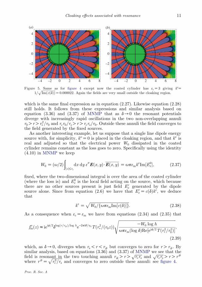
Figure 5. Same as for figure 4 except now the coated cylinder has 3cZ3 giving keZ1=
ffiffiffiffiffiffiffiffiffiffiffiffiffiffiffiffiffiffiImðcðdÞÞ
pZ0:000022. Again the fields are very small outside the cloaking region.
11Cloaking effects associated with resonance
which is the same final expression as in equation (2.27). Likewise equation (2.28)still holds. It follows from these expressions and similar analysis based onequation (3.36) and (3.37) of MNMP that as d/0 the resonant potentialsdiverge with increasingly rapid oscillations in the two non-overlapping annulir0OrOr2s =r0 and rcr0=rsOrOrcrs=r0. Outside these annuli the field converges tothe field generated by the fixed sources.
As another interesting example, let us suppose that a single line dipole energysource with, for simplicity, koZ0 is placed in the cloaking region, and that ke isreal and adjusted so that the electrical power W0 dissipated in the coatedcylinder remains constant as the loss goes to zero. Specifically using the identity(4.10) in MNMP we keep
W0 Z ðu=2Þðjzj%rs
dx dy 300Eðx; yÞ$Eðx; yÞ Zup3mkeIm½E0
x �; ð2:37Þ
fixed, where the two-dimensional integral is over the area of the coated cylinder(where the loss is) and E0
x is the local field acting on the source, which becausethere are no other sources present is just field Er
x generated by the dipolesource alone. Since from equation (2.6) we have that Er
xZcðdÞke, we deducethat
ke ZffiffiffiffiffiffiffiffiffiffiffiffiffiffiffiffiffiffiffiffiffiffiffiffiffiffiffiffiffiffiffiffiffiffiffiffiffiffiffiffiffiffiW0=fup3mIm½cðdÞ�g
p: ð2:38Þ
As a consequence when 3cZ3m we have from equations (2.34) and (2.35) that
f einðzÞzieif=2dlogðr=r#Þ=log heK2piq=g0Tðr2�=ðr0zÞÞffiffiffiffiffiffiffiffiffiffiffiffiffiffiffiffiffiffiffiffiffiffiffiffiffiffiffiffiffiffiffiffiffiffiffiffiffiffiffiffiffiffiffiffiffiffiffiffiffiffiffiffiffiffiffiffiffiffiffiffiffi
KW0 log h
up3mðlog dÞRe½eif=2Tðr2�=r20 Þ�
s;
ð2:39Þ
which, as d/0, diverges when rs!r!r# but converges to zero for rOr#. Bysimilar analysis, based on equations (3.36) and (3.37) of MNMP we see that thefield is resonant in the two touching annuli r#OrO
ffiffiffiffiffiffiffiffircrs
pand
ffiffiffiffiffiffiffiffircrs
pOrOr#
where r#Zffiffiffiffiffiffiffiffiffiffiffir3c =rs
pand converges to zero outside these annuli: see figure 4.
Proc. R. Soc. A
G. W. Milton and N.-A. P. Nicorovici12
When 3cs3m we have from equations (2.23) and (2.25) that the resonant fieldin the matrix is
f einðzÞzKhdlogðr=r�Þ=log heK2piq=g0Tðr2�=ðr0zÞÞffiffiffiffiffiffiffiffiffiffiffiffiffiffiffiffiffiffiffiffiffiffiffiffiffiffiffiffiffiffiffiffiffiffiffiffiffiffiffiffiffiffiffiffiffiffiffiffiffiffiffiffiffiffiffi
W0 log h
up3mðlog dÞIm½hTðr2�=r20 Þ�
s; ð2:40Þ
which, as d/0, diverges when rs!r!r� but converges to zero for rOr�. Bysimilar analysis, based on equations (3.35) and (3.37) in MNMP, we see that thefield is resonant in the entire annulus rc!r!r� and converges to zero outsidethis annulus: see figure 5.
Thus, even constant energy sources become invisible to an observer outsidethe cloaking region as d/0. All their energy gets trapped and absorbed in thelens. In this sense the lens behaves as a sort of ‘electromagnetic black hole’.A different sort of localization of the energy was discovered by Cui et al. (2005).They considered two opposing dipole sources on opposite sides of the losslessVeselago lens. Each source is positioned a distance d=2 from the lens. They foundthat the electromagnetic energy was confined to the layer of thickness 2dbetween the sources (i.e. the cloaking region): outside this layer the field from thenearest source cancels exactly the field from the image of the other source. Inanother recent development Guenneau et al. (2005) found that electromagneticradiation would be trapped in the vicinity of two touching corners of negativeindex material.
To obtain the corresponding cloaking results for a slab rather than acoated cylinder we let rs, rc and r0 tend to infinity while keeping dZrsKrc andd0Zr0Krs fixed. Let us define �
zZ�xC i
�yZzKrs so that the polarizable line is at
�zZd0 and so that the slab faces will be at
�xZ0 and
�xZKd. In this limit we have
r�zrsCd; r#zrs Cd=2; log hz2d=rs; logðr�=r0ÞzðdKd0Þ=rs;
logðr�rs=r20 ÞzðdK2d0Þ=rs; logðz=r0Þzð�zKd0Þ=rs;
r2�r20
z1C2dK2d0
rs;
r2�r0z
z1C2d � d0 � z_
rs:
9>>>>>>>=>>>>>>>;ð2:41Þ
Also we use the approximation, given in equation (4.3) of MNMP, thatTð1Cb=rsÞzrsQðbÞ, where
QðbÞhðNKN
dvevb
1CeifC2dvZ
peKifb=ð2dÞ
2d sin½pb=ð2dÞ� : ð2:42Þ
For a polarizable line source with these approximations (2.27) and (2.28) reduceto
f einz2dðEx CaK1ke0Þdð�zKd0Þ=2dQð2dKd0K�
zÞ=½Qð2dK2d0Þlog d�;
f oinz2dðEyKaK1ko0Þdð�zKd0Þ=2dQð2dKd0K�
zÞ=½Qð2dK2d0Þlog d�;
9=; ð2:43Þ
Proc. R. Soc. A
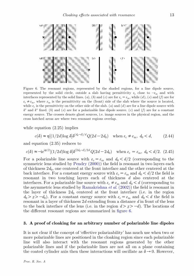
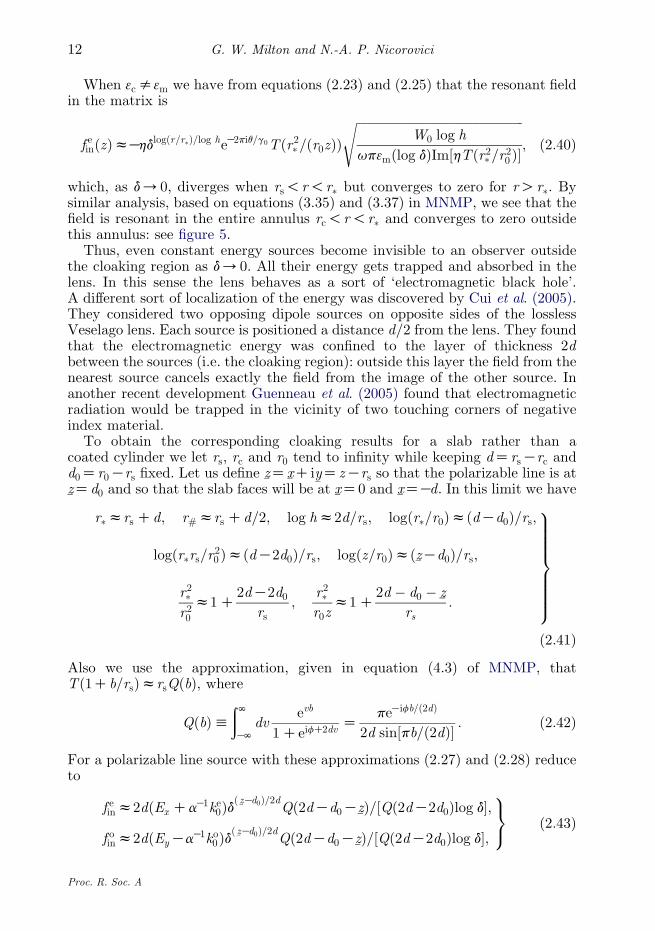
Figure 6. The resonant regions, represented by the shaded regions, for a line dipole source,represented by the solid circle, outside a slab having permittivity 3s close to K3m and withinterfaces represented by the solid lines. (a), (b) and (c) are for 3cZ3m, while (d ), (e) and (f ) are for3cs3m, where 3m is the permittivity on the (front) side of the slab where the source is located,while 3c is the permittivity on the other side of the slab. (a) and (d ) are for a line dipole source withke and ko fixed. (b) and (e) are for a polarizable line dipole source. (c) and (f ) are for a constantenergy source. The crosses denote ghost sources, i.e. image sources in the physical region, and thecross hatched areas are where two resonant regions overlap.
13Cloaking effects associated with resonance
while equation (2.25) implies
cðdÞzh½ð1=2dÞlog d�dðd0KdÞ=dQð2dK2d0Þ when 3cs3m; d0!d; ð2:44Þand equation (2.35) reduces to
cðdÞzKieif=2½ð1=2dÞlog d�dð2d0KdÞ=2dQð2dK2d0Þ when 3c Z 3m; d0!d=2: ð2:45ÞFor a polarizable line source with 3cZ3m and d0!d=2 (corresponding to thesymmetric lens studied by Pendry (2000)) the field is resonant in two layers eachof thickness 2d0, one centered at the front interface and the other centered at theback interface. For a constant energy source with 3cZ3m and d0!d=2 the field isresonant in two touching layers each of thickness d also centered at theinterfaces. For a polarizable line source with 3cs3m and d0!d (corresponding tothe asymmetric lens studied by Ramakrishna et al. (2002)) the field is resonant inthe layer of thickness 2d0 centered at the front interface (i.e. in the regiond0O�
xOKd0). For a constant energy source with 3cZ3m and d0!d the field isresonant in a layer of thickness 2d extending from a distance d in front of the lensto the back interface of the lens (i.e. in the region dO
�xOKd). The locations of
the different resonant regions are summarized in figure 6.
3. A proof of cloaking for an arbitrary number of polarizable line dipoles
It is not clear if the concept of ‘effective polarizability’ has much use when two ormore polarizable lines are positioned in the cloaking region since each polarizableline will also interact with the resonant regions generated by the otherpolarizable lines and if the polarizable lines are not all on a plane containingthe coated cylinder axis then these interactions will oscillate as d/0. However,
Proc. R. Soc. A
G. W. Milton and N.-A. P. Nicorovici14
we will see here that nevertheless the dipole moment of each polarizable line inthe cloaking region must go to zero as d/0 and in such a way that no resonantfield extends outside the cloaking region. This is not too surprising. Based on theresults for a single dipole line we expect that a resonant field extending outsidethe cloaking region would cost infinite energy, and the only way to avoid this isfor the dipole moment of each polarizable line in the cloaking region to go to zeroas d/0.
Here we limit our attention to the cylindrical lens with the core having(approximately) the same permittivity as the matrix. Also to simplify theanalysis we assume the core (but not the matrix) has some small loss. Specificallywe assume
3m Z 1; 3s ZK1C ies; 3c Z 1C iec; ð3:1Þ
with es and ec having positive real parts and approaching zero in such a way thatthe ratio gZec=es, which could be complex, remains fixed and f given byequation (2.1) also remains fixed. In this limit (2.1) implies ðesCecÞesz4deif andsince es and ec have positive real parts we deduce that f is not equal to p orKp.Using the relation gZec=es we see that
es Z 2ffiffiffid
peif=2=
ffiffiffiffiffiffiffiffiffiffiffiffi1Cg
p; ec Z 2
ffiffiffid
peif=2g=
ffiffiffiffiffiffiffiffiffiffiffiffi1Cg
p: ð3:2Þ
The potential in the core due to a single dipole at z0, with jz0jOrs is
Vcðr; q; z0ÞZ ½f ec ðz; z0ÞC f ec ð�z; �z0Þ�=2C ½f oc ðz; z0ÞKf oc ð�z; �z0ÞÞ�=ð2iÞ; ð3:3Þ
where zZreiq, z0Zr0eiq0 , and
f pc ðz; z0ÞZXN[Z0
Ep[ ðz0Þz
[; ð3:4Þ
for pZe and pZo, and for all [s0
Ep[ ðz0ÞZ
KkpbðdÞðh=z0Þ[
r0ð1Cdeifh[Þ ; bðdÞh 43sð3sK3cÞð1K3sÞ
; ð3:5Þ
and bðdÞ depends on d through the dependence of 3s and 3c on d but tends to 1 asd/0. Here ke and ko are the amplitudes of the dipole components which haveeven and odd symmetry about the line qZq0, respectively. These formulae agreewith the formulae given in equations (2.5) and (3.13) of MNMP when z0Zr0 isreal, and since the rotational invariance property Vcðr; q; z0ÞZVcðr; qKq0; r0Þ issatisfied we deduce that the formula is correct when z0 is complex. (In theformula for Ep
[ ðz0Þ the requirement of rotational invariance necessitates thefactor of 1=ðr0z[0Þ, rather than say a factor of 1=z[C1
0 ).If there are m dipoles at z1; z2;.; zm (where ziszj for all isj) all outside the
coated cylinder then, by the superposition principle, the potential in the core is
Vc ZXN[Z0
Eð1Þ[ z[ CE
ð2Þ[ �z[; ð3:6Þ
Proc. R. Soc. A
15Cloaking effects associated with resonance
where for [s0
Eð1Þ[ Z
h[bðdÞð1Cdeifh[Þ
XmjZ1
ðkð1Þj =rjÞð1=zjÞ[;
Eð2Þ[ Z
h[bðdÞð1Cdeifh[Þ
XmjZ1
ðkð2Þj =rjÞð1=�zjÞ[;
ð3:7Þ
in which
kð1Þj Z ðKkej C ikoj Þ=2; k
ð2Þj ZKðkej C ikoj Þ=2: ð3:8Þ
Let us suppose the dipoles positioned at z1; z2;.; zg with 1%g%m are in thecloaking region, while the remainder of the dipoles are outside the cloakingregion, i.e.
jzj j%r# for all j%g; jzj jOr# for all jOg; ð3:9Þ
where we allow for the special case where some of the dipoles have jzj jZr#: as wewill see, these are also cloaked. We do not specify how the set of dipole momentsfk1; k2;.; kmg depends on d except for the following.
(i) We assume that each dipole outside the cloaking region has moments whichconverge to fixed limits as d/0
limd/0
ðkej ðdÞ; koj ðdÞÞZ ðkej0; koj0Þ for all jOg: ð3:10Þ
The dipole moments kej ðdÞ and koj ðdÞ inside or outside the cloaking region are
assumed to depend linearly on the field acting upon them, since non-linearities would generate higher order frequency harmonics. Some of themcould be energy sinks, although at least one of them should be an energysource.
(ii) We assume that the energy absorbed per unit time per unit length of thecoated cylinder remains bounded as d/0, as, e.g. must be the case if theline sources only supply a finite amount of energy per unit time per unitlength. We let Wmax be the maximum amount of energy available per unittime per unit length. It is supposed that the quasistatic limit is being takennot by letting the frequency u tend to zero, but instead by fixing thefrequency u and reducing the spatial size of the system and using acoordinate system which is appropriately rescaled.
We need to show that, because the energy absorption in the core remainsbounded, the dipole moments in the cloaking region go to zero as d/0 and theresonant field does not extend outside the cloaking region, r%r#. This iscertainly true when only one polarizable line is present but as cancellation effectscan occur (the energy absorption associated with two line dipoles can be less thanthe absorption associated with either line dipole acting separately) a proof isneeded.
To do this, we bound kei and koi for any given i%g using the fact that theenergy loss within the lens is bounded by Wmax. If WcZWcðdÞ represents
Proc. R. Soc. A
G. W. Milton and N.-A. P. Nicorovici16
the energy dissipated in the core, then we have the inequality
Wc Z ðu=2Þ300cðrc0r dr
ð2p0
dqEðzÞ$EðzÞRðu=2Þ300cðrc0r dr
!
ð2p0
dqExðzÞExðzÞ; ð3:11Þ
in which 300cZImð3cÞZReðecÞ and ExðzÞ is the x component of the electric field inthe core given by
ExðzÞZKvVc
vxZK
XN[Z1
[r[K1ðEð1Þ[ eið[K1Þq CE
ð2Þ[ eKið[K1ÞqÞ: ð3:12Þ
Substituting this expression for the electric field back in equation (3.11) andusing the orthogonality properties of Fourier modes we then have
2Wc=uR2p300c
ðrc0drðEð1Þ
1 CEð2Þ1 ÞðEð1Þ
1 CEð2Þ1 ÞrC
XN[Z2
[2r2[K1ðEð1Þ[ E
ð1Þ[ CE
ð2Þ[ E
ð2Þ[ Þ
Rp300c r2c ðE
ð1Þ1 CE
ð2Þ1 ÞðEð1Þ
1 CEð2Þ1 ÞCp300c
XN[Z2
[r2[c ðEð1Þ[ E
ð1Þ[ CE
ð2Þ[ E
ð2Þ[ Þ
Rp300cXnCmK1
[Zn
[r2[c ðEð1Þ[ E
ð1Þ[ CE
ð2Þ[ E
ð2Þ[ ÞZp300c
XmK1
kZ0
bkðUkUkCVkVk Þ;
ð3:13Þwhere the last identity is obtained using equation (3.7) with the definitions
bkhðnCkÞðr�=riÞ2nC2k jbðdÞ=ð1CdhnCkeifÞj2;
UkhXmjZ1
ujðri=zjÞk ; ujhðri=zjÞnkð1Þj =rj ;
VkhXmjZ1
vjðri=�zjÞk ; vjhðri=�zjÞn=kð2Þj =rj ;
9>>>>>>>=>>>>>>>;
ð3:14Þ
in which kZ[Kn, nR2 remains to be chosen, and i%g. From equation (3.14) itfollows that UZMu and VZMv, where M is the Vandermonde matrix
MZ
1 1 1 . 1
ri=z1 ri=z2 ri=z3 . ri=zm
ðri=z1Þ2 ðri=z2Þ2 ðri=z3Þ2 . ðri=zmÞ2
« « « 1 «
ðri=z1ÞmK1 ðri=z2ÞmK1 ðri=z3ÞmK1 . ðri=zmÞmK1
0BBBBBBBB@
1CCCCCCCCA: ð3:15Þ
From the well-known formula for the determinant of a Vandermonde matrix itfollows that M is non-singular. Therefore there exists a constant ciO0 (which isthe reciprocal of the norm of MK1 and which only depends on i, m and the zj)
Proc. R. Soc. A
17Cloaking effects associated with resonance
such that jU jRcijuj and jV jRcijvj, implying
jU j2CjV j2Rc2i ðjuj2Cjvj2ÞRc2i ðjuij2Cjvij2ÞZc2i ðjkð1Þi j2Cjkð2Þi j2Þ=r2i : ð3:16Þ
Next we need to select n and find a lower bound on bk which is independent of k.Let sZKlogd=logh (so dhsZ1) and take n as the smallest integer greater than orequal to s so nRsRnK1. Then since r�Ori we have
ðr�=riÞ2nRðr�=riÞ2sZdK2 logðr�=riÞ=loghZdK1=2dK2 logðr#=riÞ=logh: ð3:17Þ
Also the following inequalities hold for mK1RkR0
1Zdhs%dhn%dhnCk and dhnCk%dhsC1Ck%dhsCmZhm: ð3:18Þ
So it follows that
j1CdhnCkeifj%ah max1%t%hm
j1Cteifj; ð3:19Þ
and a is independent of d. From the bounds (3.17) and (3.19) we deduce that
bkRsðr�=riÞ2kdK1=2dK2 logðr#=riÞ=loghjbðdÞj2=a2
RKðlogd=loghÞdK1=2dK2 logðr#=riÞ=loghjbðdÞj2=a2:ð3:20Þ
Combining inequalities gives
2Wc=uRp300c jbðdÞj2ffiffiffid
pa2logh
ðKlogdÞdK2 logðr#=riÞ=loghðjU j2CjV j2Þ
Rp300c jbðdÞj2c2iffiffiffid
pa2r2i logh
ðKlogdÞdK2 logðr#=riÞ=loghðjkð1Þi j2Cjkð2Þi j2Þ; ð3:21Þ
in which the real positive prefactor has the property that
rihlimd/0
p300c jbðdÞj2c2iffiffiffid
pa2r2i logh
Z2pc2i
a2r2i loghReðeif=2g=
ffiffiffiffiffiffiffiffiffiffiffi1Cg
pÞ; ð3:22Þ
is positive and non-zero, where ReðwÞ denotes the real part of w. So there exists ad0 such that, for all positive d!d0 and all i%g,
p300c jbðdÞj2c2iffiffiffid
pa2r2i logh
Rr=2; where rhmini%g
riO0: ð3:23Þ
By the triangle inequality we have
jkð1Þi j2Cjkð2Þi j2Zjkð1Þi j2CjKkð2Þi j2Rmaxfjkei j2;jkoi j2g; ð3:24Þ
and so we conclude that
jkpi j%2dlogðr#=riÞ=loghffiffiffiffiffiffiffiffiffiffiffiffiffiffiffiffiffiffiffiffiffiffiffiffiffiffiffiffiffiffiffiffiKWc=ður logdÞ
p; ð3:25Þ
which forces the dipole moment kpi to go to zero as d/0 (even when riZr#)because WcZWcðdÞ%Wmax.
Proc. R. Soc. A
G. W. Milton and N.-A. P. Nicorovici18
Now the superposition principle implies that the potential at any point z in thematrix is
V ðzÞZXmjZ1
kej Vej ðzÞCkoj V
oj ðzÞ; ð3:26Þ
where V ej ðzÞ (or V o
j ðzÞ) is the potential in the matrix due to an isolated linedipole at the point zj with kej Z1, koj Z0 (respectively with kej Z0, koj Z1). Now
according to theorem 3.2 in MNMP (which is easily extended to the case treatedhere where 3c depends on d) it follows that for jzjOmaxfrs; r2#=rjg,
limd/0
V pj ðzÞZ ~V
pj ðzÞZ ½~f ej ðzÞC~f
ej ð�zÞ�=2C ½~f oj ðzÞK~f
oj ð�zÞ�=ð2iÞ; ð3:27Þ
where, because 3c approaches 3m,
~fej ðzÞZ ½1=ðzKzjÞC1=ð�zK�zjÞ�=2; ~f
oj ðzÞZ ½1=ðzKzjÞK1=ð�zK�zjÞ�=ð2iÞ: ð3:28Þ
Also as shown above equation (3.27) in MNMP if r2#=rjO jzjOrs, then V pj ðzÞ
diverges as dKa where aZ logðr�rs=rj jzjÞ=log h. If zj is outside the cloaking region(i.e. jOg) then r2#=rj will be less than r#. So using the well-known fact that
limd/0
eðdÞf ðdÞZ e0f0; where e0 Z limd/0
eðdÞ; f0 Z limd/0
f ðdÞ; ð3:29Þ
it follows that
limd/0
kpj Vpj ðzÞZ kpj0
~Vpj ðzÞ for all jzjOr#; jOh; pZ e; o: ð3:30Þ
If zi is inside the cloaking region (i.e. i%g) and jzjOr2#=ri then equations (3.27),(3.29) and the fact that jkpi j tends to zero implies that kpi V
pi ðzÞ will tend to zero. For
r2#=riO jzjOr# we have that V pi ðzÞ scales as dKa with aZ logðr�rs=ðrijzjÞÞ=log h
while from equation (3.25) kpi scales at worst as db=ðKlog dÞ with bZ logðr#=riÞ=log h. So their product kpi V
pi ðzÞ will scale at worst as dbKa=ðKlog dÞ where
bKaZ logðjzj=r#Þ=log h. This goes to zero as d/0 when jzjOr#. By taking thelimit d/0 of both sides of equation (3.26) we conclude that
limd/0
V ðzÞZXm
jZhC1
kej0 ~Vej ðzÞCkoj0 ~V
oj ðzÞ for all jzjOr#; ð3:31Þ
which proves that the coated cylinder and all the line dipoles inside the cloakingregion are invisible outside the cloaking region in this limit.
More can be said if there is only one dipole line outside the cloaking region, i.e.gZmK1, and the dipoles inside the cloaking region are always quasistaticenergy sinks, in the sense that for all j%g the inequality
Im½�kej E0ðjÞx K�k
oj E
0ðjÞy �%0; ð3:32Þ
is satisfiednomatterwhat is thevalueof thefield ðE0ðjÞx ;E
0ðjÞy Þ actingonthe linedipole
at zj . For example, if the line dipole at xj responds linearly to the local field with
kej
Kkoj
!Zaj
E0ðjÞx
E0ðjÞy
0@
1A for all j%g; ð3:33Þ
Proc. R. Soc. A
19Cloaking effects associated with resonance
then equation (3.32) will be satisfied provided ajCaTj has a positive semidefinite
imaginary part.From equation (4.10) of MNMP, generalized to allow for more than one line
dipole, it follows that
Wc%ðu=2Þðjzj%rs
dx dy 300Eðx; yÞ$Eðx; yÞ ZupXmjZ1
Im½�kej E0ðjÞx K�k
oj E
0ðjÞy �
%upIm½�kemE0ðmÞx K�k
omE
0ðmÞy �%upj�kemE0ðmÞ
x K�komE
0ðmÞy j
%up½jkemjjE0ðmÞx jC jkomjjE0ðmÞ
y j�:
ð3:34Þ
Also equation (3.26) implies
E0ðmÞx Z
XgjZ1
kej EeðjÞx ðzmÞCkoj E
oðjÞx ðzmÞ; E0ðmÞ
y ZXgjZ1
kej EeðjÞy ðzmÞCkoj E
oðjÞy ðzmÞ;
ð3:35Þwhere
EpðjÞx ðzÞhK
vV pj ðzÞvx
; EpðjÞy ðzÞhK
vV pj ðzÞvy
: ð3:36Þ
So we have
jE0ðmÞx j%
XgjZ1
jkej jjEeðjÞx ðzmÞjC jkoj jjEoðjÞ
x ðzmÞj;
jE0ðmÞy j%
XgjZ1
jkej jjEeðjÞy ðzmÞjC jkoj jjEoðjÞ
y ðzmÞj:
9>>>>=>>>>;
ð3:37Þ
Now from equation (3.25) when d!d0
jkpi j%2dlogðr#=rmaxÞ=log hffiffiffiffiffiffiffiffiffiffiffiffiffiffiffiffiffiffiffiffiffiffiffiffiffiffiffiffiffiffiffiffiffiKWc=ður log dÞ
p; where rmaxhmax
i%gri; ð3:38Þ
and this with the inequalities (3.34) and (3.37) implies
Wc%jdlogðr#=rmaxÞ=log hffiffiffiffiffiffiffiffiffiffiffiffiffiffiffiffiffiffiffiffiffiffiffiffiffiffiKuWc=log d
p; ð3:39Þ
where
jZ 2pffiffiffiffiffiffiffiffiffiffiffið1=rÞ
p XgjZ1
jkemjðjEeðjÞx ðzmÞjC jEoðjÞ
x ðzmÞjÞC jkomjðjEeðjÞy ðzmÞjC jEoðjÞ
y ðzmÞjÞ:
ð3:40Þ
As d/0 this tends to
j0 Z 2pffiffiffiffiffiffiffiffiffiffiffið1=rÞ
p XgjZ1
jkemjðj ~EeðjÞx ðzmÞjC j ~EoðjÞ
x ðzmÞjÞC jkomjðj ~EeðjÞy ðzmÞjC j ~EoðjÞ
y ðzmÞjÞ;
ð3:41Þ
Proc. R. Soc. A
G. W. Milton and N.-A. P. Nicorovici20
where
~EpðjÞx ðzmÞZK
v ~Vpj ðzÞvx
; ~EpðjÞy ðzmÞZK
v ~Vpj ðzÞvy
: ð3:42Þ
So there exists a positive d1!d0 such that j%2j0 for all d!d1 and fromequation (3.39) we deduce that
Wc%K4uj20d
2 logðr#=rmaxÞ=logðhÞ=log d; ð3:43Þ
which goes to zero as d/0. Similarly the energy absorption in the shell goes tozero as d/0. Combining this with equation (3.25) gives an improved bound onthe ith dipole moment in the cloaking region:
jkpi j%K4j0
ffiffiffiffiffiffiffiffiffiffiffið1=rÞ
pdlog½r
2#=ðrmaxriÞ�=log h=log d: ð3:44Þ
For r2#=rjO jzjOrmax we have thatVpj ðzÞ scales as dKa with aZ logðr2#=ðrj jzjÞÞ=log h
while kpj scales at worst as db=ðKlog dÞ with bZ log½r2#=ðrjrmaxÞ�=log h. So theirproduct kpj V
pj ðzÞ will scale at worst as dbKa=ðKlog dÞ where bKaZ logðjzj=rmaxÞ=
log h. This goes to zero as d/0 when jzjOrmax. So all the dipoles in the cloakingregion will have vanishingly small contribution to the potential V ðzÞ outside theradius rmax.Therewill be a resonantfield in the regionbetween rmax and r# if andonlyif r2#=rmOrmax and even if this resonant field is present, its asymptotic formwill notbe influenced by the dipoles in the cloaking region.
By the superposition principle this last result extends to the case where anarbitrary number of line dipoles lie outside the cloaking region provided theirmoments ðkej ; koj Þ for jOg do not depend on d and provided the line dipoles insidethe cloaking region have a linear response of the form (3.33) with the imaginarypart of ajCaT
j being positive semidefinite for all j%g.
4. Cloaking properties of the Veselago slab lens
Let us now move away from quasistatics and investigate the cloaking propertiesof the Veselago slab lens at fixed but arbitrary frequency u. We assume the lenshas relative permittivity 3sZK1C ie and relative permeability msZK1C in,where e and n are now assumed to be real, and that the surrounding medium hasrelative permittivity and relative permeability both equal to 1.
We assume that the source is a line electrical dipole positioned along theZ-axis, ðx; yÞZð0; 0Þ with the slab faces at the planes xZd0 and xZd0Cd, withd being the slab thickness and d0 being the distance from the source to the lens.For TM polarization all the electromagnetic field components are easilycalculated once one has determined the only non-zero component of themagnetic field HZðx; yÞ, where we have used a capital Z for the z-coordinate toavoid confusion with zZxC iy. By the superposition principle HZðx; yÞ is givenby the expression
HZðx; yÞZðNKN
dkyaðkyÞtðx; y; kyÞ; ð4:1Þ
Proc. R. Soc. A
21Cloaking effects associated with resonance
where for a line dipole source
aðkyÞZKu½keðky=kxÞC iko�=2; with kx Zffiffiffiffiffiffiffiffiffiffiffiffiffiffiffiffiffiffiffiffiffiffiu2=c2Kk2y
q; ð4:2Þ
in which ke is the (possibly complex) strength of the dipole component which hasan electric field component Exðx; yÞ with even symmetry about the x-axis (i.e.with Exðx;KyÞZExðx; yÞ and HZðx;KyÞZKHZðx; yÞ) and ko is the (possiblycomplex) strength of the dipole component which has Exðx; yÞ with odd symmetryabout the x-axis (i.e. with Exðx;KyÞZKExðx; yÞ and HZðx;KyÞZHZðx; yÞ): thesehave been normalized so that they are consistent with the quasistatic definitionsof ke and ko (which are not to be confused with wavevectors such as kx and kywhich have subscripts). The transfer function tðx; y; kyÞ represents the solutionfor HZ when a plane wave with an incident field H inc
Z ZeiðkxxCkyyKutÞ comestowards the lens from the left. Let tmðx; y; kyÞ, tsðx; y; kyÞ and tcðx; y; kyÞ denotethe expressions for tðx; y; kyÞ in front (to the left) of the slab lens, in the slablens, and behind (to the right) of the slab lens, respectively. In each regiontðx; y; kyÞ is a linear combination of two plane waves except behind the slab lens,where there is only an outgoing plane wave. The coefficients can be determinedfrom the requirement of continuity of the tangential components of the magneticand electric fields across each interface, i.e. from the continuity of tðx; y; kyÞ andð1=3Þvtðx; y; kyÞ=vx. In this way explicit expressions for these transfer functionscan be derived (e.g. Kong (2002) and Podolskiy & Narimanov (2005)) but herewe will only need their asymptotic forms.
For fixed ky we have
lime;n/0
tðx; y; kyÞZ t0ðx; y; kyÞheiðkxxCkyyÞ for x!d0;
hei½kxð2d0KxÞCkyy� for d0!x!dCd0;
hei½kxðxK2dÞCkyy� for xOdCd0: ð4:3Þ
Let us choose a very large positive number kc which is to remain fixed as e; n/0.Then the integral (4.1) can be rewritten as
HZðx; yÞZ ½Aðx; yÞCBðx; yÞCCðx; yÞ�; ð4:4Þ
whereAðx; yÞZ
ÐNkcdkyaðkyÞtðx; y; kyÞ;
Bðx; yÞZÐ kcKkc
dkyaðkyÞtðx; y; kyÞ;
Cðx; yÞZÐKkcKN dkyaðkyÞtðx; y; kyÞ;
9>>=>>; ð4:5Þ
and let us define
H 0Zðx; yÞZ lim
e;n/0Bðx; yÞZ
ðkcKkc
dkyaðkyÞt0ðx; y; kyÞ: ð4:6Þ
It follows from equation (4.3) that this field has the mirroring properties
H 0Zðx; yÞZH 0
Zð2d0Kx; yÞ for 0!x!2d0;
H 0Zðx; yÞZH 0
Zð2d0 C2dKx; yÞ for d0!x!d0 C2d;
)ð4:7Þ
Proc. R. Soc. A
G. W. Milton and N.-A. P. Nicorovici22
which combine to give the shifting property
H 0Zðx; yÞZH 0
ZðxK2d; yÞ for 2d!x!d0C2d; ð4:8Þthat is responsible for the superlensing.
In the region 0!x!d0 the field H 0Zðx; yÞ is approximately that due to the dipole
line with the lens absent, except near the plane xZ0. Incidentally, the analyticcontinuation of this field to the region x!0 will be an enormously large field withspatial oscillations on the length scale of 1=kc. In the region d0!x!2d0 the fieldH 0
Zðx; yÞ is approximately that due to a solitary ghost line dipole at ðx; yÞZð2d0; 0Þ,except near the plane xZ2d0. Similarly, in the region 2d!x!d0C2d the fieldH 0
Zðx; yÞ is approximately that due to a solitary ghost line dipole at ðx; yÞZð2d; 0Þ,except near the plane xZ2d. In the region 2d0!x!2d the field H 0
Zðx; yÞ will beenormously large (but bounded for fixed kc) with spatial oscillations on the lengthscale of 1=kc. In this region and in the region 2d0Kd!x!d the fieldH 0
Zðx; yÞwill bedwarfed by the field Aðx; yÞCCðx; yÞ for sufficiently small d.
For large jkyj and small loss (i.e. small e and n) very good approximations tothe transfer functions have been derived by Podolskiy & Narimanov (2005) andPodolskiy et al. (2005) and are given by
tmðx; y; kyÞzeKkxCikyy Cixekð2dK2d0CxÞ
1Cx2e2kdeikyy;
tsðx; y; kyÞzekðxK2d0Þ C ixekð2dKxÞ
ð1C ixÞð1Cx2e2kdÞeikyy;
tcðx; y; kyÞzekð2dKxÞ
1Cx2e2kdeikyy;
9>>>>>>>>>>=>>>>>>>>>>;
ð4:9Þ
in which kZffiffiffiffiffiffiffiffiffiffiffiffiffiffiffiffiffiffiffiffiffiffik2yKu2=c2
qand x is the loss function
xZ1
2eC
eCn
2ðk2yc2=u2K1Þ
� �; ð4:10Þ
where the first expression has been kindly supplied to us by Viktor Podolskiy(2005, personal communication). For very large jkyj and very small loss, we havethat xze=2 and kzjkyj so the approximate expressions for the transfer functionsreduce to
tmðx; y; kyÞzeKjky jxCikyy Ciðe=2Þejky jð2dK2d0CxÞ
1Cðe=2Þ2e2jky jdeikyy;
tsðx; y; kyÞzejky jðxK2d0ÞC iðe=2Þejky jð2dKxÞ
1Cðe=2Þ2e2jky jdeikyy;
tcðx; y; kyÞzejky jð2dKxÞ
1Cðe=2Þ2e2jky jdeikyy;
9>>>>>>>>>>=>>>>>>>>>>;
ð4:11Þ
and in this limit
aðkyÞzKu½keðky=jkyjÞC iko�=2: ð4:12Þ
Proc. R. Soc. A
23Cloaking effects associated with resonance
The important observation is that these asymptotic expressions (with theexception of the scale factor of u in equation (4.12)) are independent of thefrequency u. Since whether or not the integrals Aðx; yÞ and Cðx; yÞ converge ordiverge as 3 and n tend to zero is determined by the asymptotic form of thetransfer functions we conclude that the resonant regions at any frequency mustbe located in the same areas as in the quasistatic limit, i.e. in two layers of equalthickness, one centered at the front interface of the lens and the other centered atthe back interface. Furthermore the asymptotic expressions for the fields in theresonant regions should be the same expressions as those in the quasistatic limit,given by equations (4.6)–(4.9) of MNMP, and as a result the effectivepolarizability should be the same as in the quasistatic case.
Let us now directly see this. We need to estimate integrals of the form
I ðbÞhðNkc
dkyekyb
1Cðe=2Þ2e2dkyZ
ðKkc
KNdky
eKkyb
1Cðe=2Þ2eK2dky; ð4:13Þ
for complex values of bZb0C ib00 in the limit as e/0. Clearly if b0 is negative wehave the estimate
jI ðbÞj%ðNkc
dkyjekybjZðNkc
dkyekyb
0ZKeb
0kc=b0; ð4:14Þ
and since kc is large the integral is negligibly small except when b0 is very small.When b0O0 let the transition point kt be defined by ðe=2ÞedktZ1, i.e.ktZKð1=dÞlogðe=2Þ, and let us change the variable of integration from ky tovZkyKkt. Then the integral becomes
I ðbÞZ ektbðNkcKkt
dvevb
1Ce2dvzektb
ðNKN
dvevb
1Ce2dvZ ðe=2ÞKb=dQ0ðbÞ; ð4:15Þ
where Q0ðbÞ is obtained by setting fZ0 in the integral (2.42) giving
Q0ðbÞZp
2d sin½pb=ð2dÞ� : ð4:16Þ
In making the approximation (4.15) we have assumed that e is so incredibly smallthat ktZKð1=dÞlogðe=2Þ[kc. From equation (4.15) we see that ðe=2ÞI ðbÞzðe=2ÞðdKbÞ=dQ0ðbÞ and a quantity like this is negligible in the limit e/0 whenb0!d.
Let Amðx; yÞ, Asðx; yÞ, Acðx; yÞ and Bmðx; yÞ, Bsðx; yÞ, Bcðx; yÞ denote thevalues of Aðx; yÞ and Bðx; yÞ in front of the lens, in the slab, and behind the lens,respectively. Using the approximations (4.11) and (4.12) we have
Amðx; yÞzK½uðkeC ikoÞ=2�iðe=2ÞI ð2dK2d0 CzÞ;Bmðx; yÞz½uðkeKikoÞ=2�iðe=2ÞI ð2dK2d0 C�zÞ;Asðx; yÞzK½uðke C ikoÞ=2�½I ðzK2d0ÞC iðe=2ÞI ð2dK�zÞ�;Bsðx; yÞz½uðkeKikoÞ=2�½I ð�zK2d0ÞC iðe=2ÞI ð2dKzÞ�;Acðx; yÞzK½uðkeC ikoÞ=2�I ð2dK�zÞ;Bcðx; yÞz½uðkeKikoÞ=2�I ð2dKzÞ:
9>>>>>>>>>>=>>>>>>>>>>;
ð4:17Þ
Proc. R. Soc. A
G. W. Milton and N.-A. P. Nicorovici24
From these expressions we see that for fixed ke and ko the field HZðx; yÞ isresonant inside two possibly overlapping layers each of thickness 2ðdKd0Þ onecentered at the front interface of the slab and the other centered at the backinterface of the slab. Podolskiy et al. (2005) had already found that the fields arevery large in front of the lens outside the quasistatic regime, and we now see thatthey become infinitely large as e/0.
Substituting the approximation (4.15) into (4.17) yields expressions for HZðx; yÞin the resonant regions. In each resonant region
HZðx; yÞzGðx; yÞhsuf½geðzÞKgeð�zÞ�=2C ½goðzÞCgoð�zÞ�=ð2iÞg; ð4:18Þwhere Gðx; yÞ is a piecewise harmonic function of x and y, and the prefactor s,which is 1 inside the lens and K1 outside the lens, is introduced to make thecomparison with the quasistatic results easier. One finds that for pZe; o in theresonant region 2d0Kd!x!d0 in front of the slab
gpðzÞZ gpmðzÞhKiqkpðe=2Þð2d0KdKzÞ=dQ0ð2dK2d0 CzÞ; ð4:19Þwhere qZ1 for pZe and qZK1 for pZo, while in the resonant region dCd0!x!2d behind the slab
gpðzÞZ gpc ðzÞhkpðe=2ÞðzK2dÞ=dQ0ð2dKzÞ: ð4:20ÞWithin the slab, for x!minf2d0; dg, one has the resonant potential
gpðzÞZ gpoutðzÞhKikpðe=2ÞðzKdÞ=dQ0ð2dKzÞ; ð4:21Þwhich is associated with the front interface and for xOmaxfd; 2d0g one has theresonant potential
gpðzÞZ gpinhqkpðe=2Þð2d0KzÞ=dQ0ðzK2d0Þ; ð4:22Þwhich is associated with the back interface, and when d0!d=2 for 2d0!x!d onehas the resonant potential gpðzÞZgpinðzÞCgpoutðzÞ where the resonant regionsoverlap. Here the notations ‘in’ and ‘out’ are introduced to be consistent with thenotations in equations (4.8) and (4.9) of MNMP.
The above expressions for gpmðzÞ, gpc ðzÞ, gpoutðzÞ, and gpinðzÞ agree precisely withthe asymptotic expressions for f pinð�zÞ, �
f pcð�zÞ
�f pout
ð�zÞ, and
�f pinð�zÞ, respectively, in
equations (4.6)–(4.9) of MNMP with the identification�zZd0Kz corresponding
to the different coordinate system used in that paper, with fZ0 corresponding tothe trajectory choice 3sZ1C ie chosen here, and with the signs of ke and ko
changed due to the 1808 rotation associated with the different coordinate system(a dipole rotated by 1808 has opposite sign).
Also since ezs the formula (4.18) is consistent with the formula (2.7) inMNMP for the magnetic field HZ once one replaces u withKu because the timedependence in that paper has the factor eiut rather than eKiut. It is not surprisingthat HZ becomes asymptotically harmonic in each resonant region as e/0 sincein this limit in the equation ðV2Cu2m3ÞHZZ0 satisfied by HZ the spatialderivatives dominate because of the huge gradients in the field HZ .
From Maxwell’s equation V!HZKiu3E we see that in each resonant region
Exðx; yÞzErx ðx; yÞhKvV ðzÞ=vx; Eyðx; yÞzEr
y ðx; yÞhKvV ðzÞ=vy; ð4:23Þwhere
V ðzÞh ½geðzÞCgeð�zÞ�=2C ½goðzÞKgoð�zÞ�=ð2iÞ: ð4:24Þ
Proc. R. Soc. A
25Cloaking effects associated with resonance
In particular, in the resonant region in front of the lens, we have
Erx ðx; yÞZK½ge0mðzÞCge0mð�zÞ�=2K½go0mðzÞKgo0mð�zÞ�=ð2iÞ;
Ery ðx; yÞZKi½ge0mðzÞKge0mð�zÞ�=2K½go0mðzÞCgo0mð�zÞ�=2;
)ð4:25Þ
where
gp0mðzÞZ dgpmðzÞ=dz Z iqkp½ð1=dÞlogðe=2Þ�ðe=2Þð2d0KdKzÞ=dQ0ð2dK2d0 CzÞ
Kiqkpðe=2Þð2d0KdKzÞ=dQ 00ð2dK2d0CzÞ
ziqkp½ð1=dÞlogðe=2Þ�ðe=2Þð2d0KdKzÞ=dQ0ð2dK2d0CzÞ;ð4:26Þ
if which we have assumed jlogðe=2Þj[1. As can be seen from these equations, thefields Er
x ðx; yÞ and Ery ðx; yÞ have an approximately exponential decay away from
front of the slab face, i.e. they decay as ex=t with a decay length tZd=jlogðe=2Þjwhich depends on e and d but which is independent of the frequency u and which isroughly of the order of d if e is not too small. This is in contrast to most evanescentfields which typically have a decay length which is of the order of the wavelength.
The Z-axis, which is where the dipole source is located, will be in the resonantregion when d0!d=2 and the resonant field ðEr
x ;Ery ÞZðEr
x ð0; 0Þ;Ery ð0; 0ÞÞZ
ðKgemð0Þ;Kgo0mð0ÞÞ acting on it will be given by equation (2.6) with
cðdÞzcðe2=4ÞzKi½ð1=dÞlogðe=2Þ�ðe=2Þð2d0KdÞ=dQ0ð2dK2d0Þ; ð4:27Þwhich is in agreement with equation (2.45) when one sets dZe2=4 and fZ0 inaccordance with equation (2.2). Now suppose that the source being considered is anelectrically polarizable line source satisfying equation (2.7) in which ðE0
x ;E0y Þ is the
total field acting on the line source. Also suppose that there are other fixed sources,possibly on both sides of the slab lens, that lie outside the cloaking region, i.e. whichare more than a distance d=2 away from the slab. We assume these fixed sources arenot perturbed if we remove the polarizable line and we let ðEx ;EyÞ denote the field atthe Z-axis due to these sources and the slab lens when the polarizable line source isabsent. Then it is easy to check that equations (2.7)–(2.26) remain valid, implyingthat the polarizable line is cloaked at any frequency, not just in the quasistatic limit,and for very small loss the effective polarizability will be
a�zKI=cðe2=4Þz idðe=2ÞðdK2d0Þ=d
jlogðe=2ÞjQ0ð2dK2d0ÞI ; ð4:28Þ
which will be purely imaginary, with a small positive imaginary part, reflecting theloss in the lens due to the localized resonance.
When, for simplicity, the polarizability is proportional to the identity tensoraZaI , then equations (2.26), (4.19) and (4.27) imply
gemðzÞzK½Ex CaK1ke0�dðe=2ÞKz=dQ0ð2dK2d0 CzÞ
logðe=2ÞQ0ð2dK2d0Þ;
gomðzÞz½KEy CaK1ko0 �dðe=2ÞKz=dQ0ð2dK2d0 CzÞ
logðe=2ÞQ0ð2dK2d0Þ;
9>>>>>=>>>>>;
ð4:29Þ
Proc. R. Soc. A
G. W. Milton and N.-A. P. Nicorovici26
which are resonant in the layer between the source and the slab. Similarly byexamining gemðzÞ, gpout and gpin we see that just as in the quasistatic case (see figure 6)the resonance is confined to the two strips 0!x!2d0 and d!x!dC2d0 each ofthickness 2d0 and each with an interface of the slab as its midplane. The energyestimates obtained in §4 of MNMP remain valid: as e/0 the total electrical energystored in the slab will scale as
½jkej2C jkoj2�e2ðd0=dÞK2jlog ejwe2ðd0=dÞK2jlog ej=jcðe2=4Þj2weK2d0=d=jlog ej; ð4:30Þ
which goes to infinity as e/0. Consequently, if the sources are started at somedefinite time it will take an increasingly long time (but one which is apparentlyrelatively independent of the frequency u) for the energy in the resonant field tobuild up to its equilibrium value and for the polarizable line to become cloaked. Forfixed but small e the transient time will be smallest when d0=d is small since then thetotal electrical energy stored will be dramatically less. Also the cloaking effects willbe strongest when d0=d is small since then cðe2=4Þ is largest. Therefore, for cloakingpurposes, it is highly advantageous for the polarizable line to be close to the lens. Theelectrical absorption in the lens will scale like e times the above expression, i.e. aseðdK2d0Þ=d=jlog ej which goes to zero as e/0, and fastest when d0=d is small. By asimilar analysis, based on equations (4.18), (4.21), and (4.22), the total magneticfield energy HZ within the lens scales like
u2½jkej2 C jkoj2�e2ðd0=dÞK2=jlog ejwu2e2ðd0=dÞK2=ðjlog ejjcðdÞj2Þwu2eK2d0=d=jlog ej3;ð4:31Þ
which for sufficiently small ewill be much smaller than the electrical energy, but willstill go to infinity as e/0.
5. Cloaking in three dimensions
Since the asymptotic expressions (4.11) for the transfer functions (and theanalogous asymptotic expressions for the transfer functions of transverse electric(TE) fields) are independent of the frequency u the three-dimensional cloakingproperties and the effective polarizability of a polarizable point dipole in front ofthe Veselago lens at any fixed frequency should be the same as in the quasistaticlimit. Therefore, to simplify the analysis, let us restrict our attention to thequasistatic case, which anyway is more easily experimentally tested since themagnetic permeability can be positive and real everywhere.
We consider the cloaking of a polarizable point dipole in front of a slab ofrelative permittivity 3s. The region in front of the slab has relative permittivity3m and the region behind the slab has relative permittivity 3c. We assume that 3cand 3m remain fixed and that 3s approachesK3m along a trajectory in the upperhalf of the complex plane in such a way that d/0 but f remains fixed, where dand f are given by equation (2.4). It proves convenient to use x1, x2 and x3 as ourcoordinates, rather than x, y and Z, with the polarizable dipole being at xZ0 andthe slab faces being located at x1Zd0 and at x1Zd0Cd.
Proc. R. Soc. A
27Cloaking effects associated with resonance
By differentiating with respect to x1, x2, and x3 the plane wave expansion forthe potential associated with a suitably normalized point charge,
1
rZ
1
2p
ðNKN
ðNKN
dk2dk3eKkx1Ciðk2x2Ck3x3Þ
kfor x1O0; where kZ
ffiffiffiffiffiffiffiffiffiffiffiffiffiffiffiffiffiffiffiffiffiffiffik2x2Ck3x3
p;
ð5:1Þone obtains the plane wave expansion for a dipole
Ka$V½1=ð4prÞ�Z ða$xÞ=ð4pr3ÞZðNKN
ðNKN
dk2dk3aðk2; k3ÞeKkx1Ciðk2x2Ck3x3Þ; ð5:2Þ
in which
a Z ða1; a2; a3Þ; aðk2; k3ÞZ ½a1Kia2ðk2=kÞKia3ðk3=kÞ�=ð8p2Þ; ð5:3Þand a1, a2 and a3 are (apart from a constant factor) the possibly complexstrengths of the dipole components in the x1, x2, and x3 directions.
By the superposition principle the potential V ðxÞ in the slab geometry is givenby the expression
V ðxÞZðNKN
ðNKN
dk2dk3aðk2; k3Þtðx; k2; k3Þ; ð5:4Þ
where the transfer function tðx; k2; k3Þ represents the solution forVwith an incidentfieldV incZeKkx1Ciðk2x2Ck3x3Þ. Let tmðx; k2; k3Þ, tsðx; k2; k3Þ and tcðx; k2; k3Þ denote theexpressions for tðx; k2; k3Þ in front (to the left) of the slab lens, in the slab lens, andbehind (to the right) of the slab lens, respectively. These have the form
tmðx; k2; k3ÞZ eKkx1Ciðk2x2Ck3x3ÞCbmðkÞekx1Ciðk2x2Ck3x3Þ;
tsðx; k2; k3ÞZasðkÞeKkx1Ciðk2x2Ck3x3ÞCbsðkÞekx1Ciðk2x2Ck3x3Þ;
tcðx; k2; k3ÞZacðkÞeKkx1Ciðk2x2Ck3x3Þ:
9>>=>>; ð5:5Þ
The requirements of continuity of the potential t and normal component of theassociated displacement field K3 vt=vx at the interfaces xZd0 and xZdCd0determine the coefficients
bmðkÞZðe2ðdKd0Þk=hscÞKdeifhsce
K2d0k
1Cdeife2dk; asðkÞZ
23me2dk
hscð3mK3sÞð1Cdeife2dkÞ;
bsðkÞZ23me
K2d0k
ð3mK3sÞð1Cdeife2dkÞ; acðkÞZ
43s3me2dk
ð3sK3cÞð3mK3sÞð1Cdeife2dkÞ;
9>>>>=>>>>;ð5:6Þ
where hscZð3sK3cÞ=ð3sC3cÞ. Introducing the angle 4 such that k2Zk cos 4,k3Zk sin 4, then the integral (5.4) becomes
V ðxÞZð2p0
d4að4ÞðN0dk kaðkÞekðKx1Cix2cos 4Cix3sin 4Þ CkbðkÞekðx1Cix2cos 4Cix3sin 4Þ;
ð5:7Þ
Proc. R. Soc. A
G. W. Milton and N.-A. P. Nicorovici28
in which aðkÞ equals 1, asðkÞ and acðkÞ, in front of the lens, in the lens, and behindthe lens, respectively, and similarly bðkÞ equals bmðkÞ, bsðkÞ and 0, in theserespective regions, and where
að4ÞZ ða1Kia2cos 4Kia3sin 4Þ=ð8p2Þ: ð5:8ÞLet us define
JðbÞhðN0dk
kekb
1Cdeife2dk; J 0ðbÞhdJðbÞ
dbZ
ðN0dk
kbekb
1Cdeife2dk: ð5:9Þ
Then we have
VmðxÞZða$xÞ=4pr3Cð2p0d4að4Þ½Jð2dK2d0Cx1Cix2cos4Cix3sin4Þ=hsc
KdeifhscJðK2d0Cx1Cix2cos4Cix3sin4Þ�;
VsðxÞZð2p0d4að4Þ½Jð2dKx1Cix2cos4Cix3sin4Þ=hsc
CJðK2d0Cx1Cix2cos4Cix3sin4Þ�½23m=ð3mK3sÞ�;
VcðxÞZð2p0d4að4ÞJð2dKx1Cix2cos4Cix3sin4Þð43s3mÞ=½ð3sK3cÞð3mK3sÞ�:
9>>>>>>>>>>>>>=>>>>>>>>>>>>>;
ð5:10ÞThe electric field in front of the lens will be
EðxÞZKVVmZEdipðxÞCErðxÞ; ð5:11Þwhere Edip is the field due to the dipole alone,
EdipZKV½a$x=ð4pr3Þ�Z½3xða$xÞ=r2Ka�=ð4pr3Þ; ð5:12Þand ErðxÞ is the response field (which in the limit as d/0 can become the resonantfield) given by
ErðxÞZðEr1 ;E
r2 ;E
r3 Þ
Z
ð2p0d4að4Þð1;icos4;i sin4Þ½KJ 0ð2dK2d0Cx1Cix2cos4Cix3sin4Þ=hsc
CdeifhscJ0ðK2d0Cx1Cix2cos4Cix3sin4Þ�: ð5:13Þ
In particular at the origin xZ0, which is where the dipole source is located, theintegral is easily calculated and we have
Erð0ÞZcðdÞLa with LZ
1 0 0
0 1=2 0
0 0 1=2
0B@
1CA; ð5:14Þ
where
cðdÞZKJ 0ð2dK2d0Þ=ð4phscÞCdeifhscJ0ðK2d0Þ=ð4pÞ: ð5:15Þ
So far no approximation has been made.
Proc. R. Soc. A
29Cloaking effects associated with resonance
Let us now examine JðbÞ for complex values of bZb0C ib00 in the limit asd/0. If b0 is negative then we have the estimate
jJðbÞj%ðN0dk kjekbj=c0 Z 1=ðc0b02Þ; where c0 Zmin
cR0j1Cceifj; ð5:16Þ
and c0 is non-zero because f is never equal to p or Kp. So in this case JðbÞremains bounded as d/0, and
limd/0
JðbÞZðN0dk lim
d/0
kekb
1Cdeife2dkZ
ðN0dk kekb Z 1=b2: ð5:17Þ
It follows from equation (5.10) that when 3cs3m and a is fixed the potentialV ðxÞ is not resonant outside the layer 2dOx1O2ðd0KdÞ.
When b0O0 let the transition point kt be defined by de2dktZ1, i.e. byktZKð1=2dÞlog d, and let us change the variable of integration from k tovZkKkt. Then the integral becomes
JðbÞZðNKkt
dvðvCktÞeðvCktÞb
1Ce2dvz
ðNKN
dvðvCktÞeðvCktÞb
1Ce2dv; ð5:18Þ
and this latter integral can be expressed in terms of the functions QðbÞ, given byequation (2.42), and its derivative Q 0ðbÞZdQðbÞ=db:
ðNKN
dvðvCktÞeðvCktÞb
1Ce2dvZ
d
db
ðNKN
dveðvCktÞb
1Ce2dvZ
d
db½ektbQðbÞ�
Z ktektbQðbÞCektbQ 0ðbÞ
zK½ð1=2dÞlog d�dKb=2dQðbÞ;
ð5:19Þ
where we have assumed QðbÞs0 and used the fact that kt is large for extremelysmall d. Combining formulae gives
JðbÞ zK½ð1=2dÞlog d�dKb=2dQðbÞ;
J 0ðbÞZ dJðbÞ=dbz½ð1=2dÞlog d�2dKb=2dQðbÞK½ð1=2dÞlog d�dKb=2dQ 0ðbÞ
zðlog dÞ2dKb=2dQðbÞ=ð4d2Þ;
9>>>>=>>>>;
ð5:20Þ
and so for d0!d when d is very small
cðdÞzKJ 0ð2dK2d0Þ=ð4phscÞzKðlog dÞ2dðd0KdÞ=dQð2dK2d0Þ=ð16pd2hscÞ: ð5:21Þ
If 3cs3m and d/0 then hsc/1=h and the above expression gives
cðdÞzKhðlog dÞ2dðd0KdÞ=dQð2dK2d0Þ=ð16pd2Þ; ð5:22Þ
Proc. R. Soc. A
G. W. Milton and N.-A. P. Nicorovici30
which implies the dipole becomes cloaked (jcðdÞj is large) for all d0!d. In thecase when 3cZ3m then hsczieKif=2=
ffiffiffid
pfor small d and we have
cðdÞzieif=2ðlog dÞ2dð2d0KdÞ=2dQð2dK2d0Þ=ð16pd2Þ; ð5:23Þwhich implies the dipole becomes cloaked for all d0!d=2.
To justify these cloaking claims suppose the dipole at xZ0 is a polarizable‘molecule’ in the cloaking region. Let EðxÞ be the field without the polarizabledipole present due to the following.
(i) Fields generated by fixed quasistatic sources lying outside the slab (oneither side of it) and which are outside the cloaking layer.
(ii) Fields generated by the slab due to its interaction with these fixed sources.
The field E0 acting on the polarizable molecule has two components:
E0 ZEð0ÞCErð0ÞZEð0ÞCcðdÞLa; ð5:24Þwhere Erð0Þ is the field due to the interaction of the polarizable molecule withthe slab. If a denotes the polarizability tensor of the molecule (which need not beproportional to I ) and we allow for the fact that the polarizable line could have afixed dipole source term a0 then we have
a ZaE0Ca0 Za�Eð0ÞCa�; ð5:25Þwhere
a� Z ½aK1KcðdÞL�K1; a� Z ½IKcðdÞaL�K1a0; ð5:26Þare the ‘effective polarizability tensor’ and ‘effective source term’. Notice that the‘effective polarizability tensor’ is anisotropic when aZaI .
It is interesting to examine what happens if the polarizable ‘molecule’ isbehind the slab. When 3cZ3m symmetry considerations imply that the moleculewill be cloaked if it is within a distance d=2 from the slab. When 3cs3m we willsee that a molecule behind the slab will never be cloaked. To establish the latterit suffices to consider the situation where the molecule is in front of the lens and3s tends to K3c. Then equation (2.1) implies 3szðK1K2deif=hÞ3c andhsczheKif=d. It follows from equation (5.15) that
cðdÞz½KdeifJ 0ð2dK2d0Þ=hChJ 0ðK2d0Þ�=ð4pÞ: ð5:27ÞNow as d/0 equation (5.16) implies J 0ðK2d0Þ remains bounded, while equation(5.20) implies dJ 0ð2dK2d0Þ scales as ðlog dÞ2dd0=d. Therefore cðdÞ remainsbounded and no cloaking occurs.
6. Not everything is cloaked
Here we show that a layer of permittivity 32s3m is not cloaked when it isinserted in the cloaking region. Let us consider the quasistatic transferfunction tðx; k2; k3Þ associated with a multilayered system with interfaces atx1Zs1; s2; s3; s4, where 0!s1!s2!s3!s4 and in the region between sj and sjC1
the permittivity is 3jC1, while for x1!s1 it is 31 and for xOs4 it is 35. In the region
Proc. R. Soc. A
31Cloaking effects associated with resonance
occupied by the material with permittivity 3j , for jZ1; 2;.; 5 the transferfunction takes the form
tjðx; k2; k3ÞZajeKkx1Ciðk2x2Ck3x3ÞCbje
kx1Ciðk2x2Ck3x3Þ; ð6:1Þ
where a1Z1 and b5Z0. The requirements of continuity of the potential t andnormal component of the associated displacement fieldK3 vt=vx at the interfacex1Zsj imply
aj
bj
!ZM j
ajC1
bjC1
!; M j h
1
2
1C9j ð1K9jÞe2sjk
ð1K9jÞeK2sjk 1C9j
!; 9j h
3jC1
3j:
ð6:2ÞThus we have
1
b1
!ZM
a5
0
!; where M Z
m1 m2
m3 m4
� �ZM 1M 2M 3M 4; ð6:3Þ
which implies a5Z1=m1 and b1Zm3=m1. Now let us take
31 Z 33 Z 35 Z 3m Z 1; 34 Z 3s ZK1C ie; s3 Z d0; s4 Z dCd0; ð6:4Þwhere e is very small, so that the multilayered system consists of a layer ofpermittivity 32 and thickness s2Ks1 in front of a superlens and not touching it.Then we have
lime/0
M ZM 1M 2
eK2dk 0
0 e2dk
!;
and consequently a5 and b1 still depend on 32 even if the layer of permittivity 32lies entirely inside the cloaking region: thus the presence of the layer can bedetected from outside the cloaking region.
On the basis of this example one might think that cloaking does not extend tobodies of arbitrary shape. However, the example is very special in that thepotential in the region s2!x1!s0 when analytically extended into the regionx1%s2 has no singularities there, and in particular no singularities in the cloakingregion. By contrast, any object of finite extent lying entirely within the cloakingregion of the slab lens will have singularities in the analytic continuation of thepotential outside the object to the region within the object. In order for thesesingularities not to create resonant regions with infinite energy in the limit e/0it seems plausible that their effects should diminish as e/0. Therefore it may bethe case that any object of finite extent lying entirely within the cloaking regionof the slab lens will be cloaked in the limit e/0. It seems much more speculativeto suggest that an object lying half way in the cloaking region would be halfcloaked. However, if this were true it could provide an interesting way to imagethe interior of an object: when one looked through the slab lens at the object onewould only see only the back half of it!
To experimentally detect cloaking it may be necessary to use lasers to providecoherent radiation. If ordinary electromagnetic radiation were used then by thetime the resonant field responsible for the cloaking reached an equilibrium value
Proc. R. Soc. A
G. W. Milton and N.-A. P. Nicorovici32
the radiation acting on the polarizable ‘molecule’ could be out of coherence withthe resonant field acting on it. This might not be the case if the ‘molecule’ issufficiently close to the boundary since then the resonant field reaches itsequilibrium value relatively quickly. Also we have assumed that the ‘molecule’ isa stationary object, and therefore it seems possible that thermal effects coulddestroy cloaking. To minimize these effects it may be necessary to reduce thetemperature as much as possible. Moreover, it seems unlikely that cloaking couldbe achieved over a broad range of frequencies since if 3szK1 at one frequencyand we assume the loss terms are extremely small, the positivity of dðu3sÞ=du(which enters the Brillouin formula for the energy: see §80 of Landau & Lifshitz(1960)) implies that d3s=duO1=u, so there is necessarily a significant change ofthe permittivity 3s with frequency.
It should also be cautioned that we have not investigated the effects ofstability. If the time harmonic solution assumed here is unstable it seems unlikelythat cloaking could be experimentally observed.
The authors thank Alexei Efros for his insightful remarks and for his suggestion, noted in the paperMNMP, that the energy absorption in the slab lens may be infinite for a fixed source close to thelens. Also they wish to acknowledge that Arthur Yaghjian independently discovered that the fielddiverges in front of the Veselago lens (2005, personal communication). Viktor Podolskiy is thankedfor discussions regarding the resonant region in front of the slab lens and for providing theasymptotic formula for the transfer function in front of the lens. Ross McPhedran is thanked forhelpful conversations. The referees are thanked for helpful comments. G.W.M. is grateful forsupport from the National Science Foundation through grant DMS-0411035, and for the hospitalityof Sydney University during his stay there. N.A.P.N. is grateful for support from the University ofTechnology, Sydney.
References
Cherkaev, A. V. & Gibiansky, L. V. 1994 Variational principles for complex conductivity,viscoelasticity, and similar problems in media with complex moduli. J. Math. Phys. 35, 127–145.(doi:10.1063/1.530782)
Cui, T. J., Cheng, Q., Lu, W. B., Jiang, Q. & Kong, J. A. 2005 Localization of electromagneticenergy using a left-handed-medium slab. Phys. Rev. B (Solid State) 71, 045 114.
Garcia, N. & Nieto-Vesperinas, M. 2002 Left-handed materials do not make a perfect lens. Phys.Rev. Lett. 88, 207 403. (doi:10.1103/PhysRevLett.88.207403)
Guenneau, S., Gralak, B. & Pendry, J. B. 2005 Perfect corner reflector. Opt. Lett. 30, 1204–1206.(doi:10.1364/OL.30.001204)
Kong, J. A. 2002 Electromagnetic wave interaction with stratified negative isotropic media. Prog.Electromagn. Res. 35, 1–52. (doi:10.1159/000060803)
Landau, L. D. & Lifshitz, E. M. 1960 Electrodynamics of continuous media. New York, NY:Pergamon Press.
Maystre, D. & Enoch, S. 2004 Perfect lenses made with left-handed materials: Alice’s mirror?J. Opt. Soc. Am. 210, 122–131. (doi:10.1364/JOSAA.21.000122)
Merlin, R. 2004 Analytical solution of the almost-perfect-lens problem. Appl. Phys. Lett. 840,1290–1292. (doi:10.1063/1.1650548)
Milton, G. W. 2002 The theory of composites. Cambridge, UK: Cambridge University Press.Milton, G. W., Nicorovici, N.-A. P., McPhedran, R. C. & Podolskiy, V. A. 2005 A proof of
superlensing in the quasistatic regime, and limitations of superlenses in this regime due toanomalous localized resonance. Proc. R. Soc. A Math. Phys. Sci. 461, 3999–4034. (doi:10.1098/rspa.2005.1570)
Proc. R. Soc. A
33Cloaking effects associated with resonance
Nicorovici, N. A., McPhedran, R. C. & Milton, G. W. 1994 Optical and dielectric properties ofpartially resonant composites. Phys. Rev. B (Solid State) 490, 8479–8482.
Pendry, J. B. 2000 Negative refraction makes a perfect lens. Phys. Rev. Lett. 85, 3966–3969.(doi:10.1103/PhysRevLett.85.3966)
Pendry, J. B. 2004 Negative refraction. Contemp. Phys. 45, 191–202. (doi:10.1080/00107510410001667434)
Podolskiy, V. A. & Narimanov, E. E. 2005 Near-sighted superlens. Opt. Lett. 30, 75–77. (doi:10.1364/OL.30.000075)
Podolskiy, V. A., Kuhta, N. A. & Milton, G. W. 2005 Optimizing the superlens: manipulatinggeometry to enhance the resolution. Appl. Phys. Lett. 87, 231 113. (doi:10.1063/1.2139620)
Pokrovsky, A. L. & Efros, A. L. 2002 Diffraction in left-handed materials and theory of Veselagolens. See http://www.arxiv.org/abs/cond-mat/0202078.
Ramakrishna, S. A. 2005 Physics of negative refractive index materials. Rep. Prog. Phys. 68,449–521. (doi:10.1088/0034-4885/68/2/R06)
Ramakrishna, S. A., Pendry, J. B., Schurig, D., Smith, D. R. & Schultz, S. 2002 The asymmetriclossy near-perfect lens. J. Modern Opt. 490, 1747–1762.
Rao, X. S. & Ong, C. K. 2003 Amplification of evanescent waves in a lossy left-handed materialslab. Phys. Rev. B (Solid State) 68, 113103.
Shvets, G. 2003 Photonic approach to making a material with a negative index of refraction. Phys.Rev. B (Solid State) 67, 035109.
Veselago, V. G. 1968 The electrodynamics of substances with simultaneously negative values of eand m. Uspekhi Fizicheskikh Nauk 92, 517–526. (Transl. Soviet Phys. Uspekhi 1968 10, 509–514).
Proc. R. Soc. A