Embed Size (px)
Citation preview
Turkish J. Eng. Env. Sci.29 (2005) , 113 – 128.c© TUBITAK
On the Application of von Mises’ Yield Criterion to a Class ofPlane Strain Thermal Stress Problems
Ahmet N. ERASLANMiddle East Technical University, Department of Engineering Sciences
Ankara-TURKEYe-mail: [email protected]
Hakan ARGESOBaskent University, Department of Mechanical Engineering
Ankara-TURKEY
Received 10.11.2004
Abstract
A computational model is developed to estimate thermal stresses in nonlinearly hardening elastic-plasticaxisymmetric systems in cylindrical polar coordinates. The model is based on von Mises’ yield criterion,total deformation theory and Swift’s hardening law. Various numerical examples including plane strain andgeneralized plane strain problems in cylinders and tubes are handled. Comparisons are made with existinganalytical solutions employing Tresca’s yield criterion for elastic-ideally plastic and elastic-linearly hardeningsystems. Parametric analyses are carried out to investigate the effect of important model parameters on thestresses and deformations.
Key words: Thermoelastoplasticity, Nonlinear strain hardening, von Mises’ criterion, Residual stresses.
Introduction
Analysis of thermally induced deformations of rods,tubes, disks, spherical shells and other structures isof great importance in engineering design and op-eration (Boley and Weiner, 1960; Timoshenko andGoodier, 1970; Ugural and Fenster, 1995). Since ingeneral, to better utilize the material, plastic defor-mation may be admitted to some extent, recent stud-ies have focused on elastic-plastic treatment of ther-mal behavior. A special case, in which thermal defor-mations are caused by a prescribed symmetrical tem-perature distribution or internal energy generation insystems that can be treated under plane-strain pre-supposition, has been the topic of numerous inves-tigations. The elastic-plastic deformation occurringin a perfectly plastic cylinder having fixed ends sub-jected to a uniform temperature inside its cylindricalcore was studied by Orcan and Gamer (1991). Later,Gulgec and Orcan (1999) extended the analysis pre-
sented in Orcan and Gamer (1991) to include linearstrain hardening. In a closely related work, Orcan(1994a) obtained the solution of an elastic-ideallyplastic cylindrical rod with uniform internal energygeneration. All stages of the elastic-plastic defor-mation of a uniform heat generating tube with freeends were studied analytically by Orcan and Gulgec(2001), assuming perfectly plastic material behavior.Recent investigations include the numerical solutionof thermal stresses in elastic perfectly plastic tubesconsidering temperature dependent physical proper-ties by Orcan and Eraslan (2001), an analytical solu-tion of 2-layer tubes for linear hardening by Eraslanet al. (2003) and for nonlinear hardening by Eraslan(2003) and an analytical solution considering a con-vective boundary condition for fixed end cylinders byEraslan and Orcan (2004). In all these theoreticalinvestigations, Tresca’s yield criterion and its associ-ated flow rule were used.
The use of Tresca’s yield criterion in elastoplas-
113

ERASLAN, ARGESO
tic analysis for nonhardening or linear hardeningmaterials leads to linear differential equations andhence permits the analytical treatment of the prob-lem. However, in the case of thermoplasticity its useneeds separate treatment in each region due to dif-ferent forms of the yield criterion in different partsof the plastic zone. Due to various combinationsof elastic and plastic regions, the analysis dependsentirely on the temperature distribution and maychange completely if a different temperature distri-bution is imposed. Moreover, in the case when aplastic region expands over a plastically predeformedregion the task becomes quite cumbersome. Hence,to develop an algorithm for a unified treatment fordesign purposes by the use of Tresca’s yield criterionwould be a formidable task.
In this work, we suggest a simple computationalprocedure for the unified treatment of a class ofplane strain thermal stress problems taking nonlin-ear strain hardening into account. The model isbased on von Mises’ yield criterion, the deformationtheory of plasticity and a Swift-type hardening law.A shooting method using Newton iterations with nu-merically generated tangents is developed for the nu-merical solution of the nonlinear governing differen-tial equation. The major contributions of the presentmodel are the inclusion of (i) von Mises’ yield cri-terion, (ii) nonlinear isotropic hardening, (iii) anyprescribed temperature distribution and (iv) an ef-ficient numerical solution procedure. Furthermore,all combinations of solid and hollow cylinders withfixed and free end conditions can be handled. Smalland large values of the hardening parameters can beused without any difficulty.
The results of the computations are comparedwith the existing analytical solutions based onTresca’s criterion to verify the present computationalmodel. These comparisons indicate that there existsfairly good agreement in the predictions of stressand displacement distributions and relatively pooragreement in plastic strain, predictions for structuresmade of ideally-plastic and linearly hardening mate-rials. It is also observed that the elastic-plastic inter-face predicted by Tresca’s criterion advances furtherthan that of von Mises and hence, lower fully plasticlimits are predicted by Tresca’s yield criterion.
Model Development
The elastic equation
The following dimensionless and normalized vari-ables are introduced: Radial coordinate: r = r/b,inner radius: a = a/b, normal stress: σj = σj/σ0,normal strain: εj = εjE/σ0, radial displacement:u = uE/σ0b, heat load: Q = QEαb2/σ0k, coefficientof thermal expansion: α = αE/σ0, hardening pa-rameter: H = ησ0/E, with b being the outer radius,σ0 the yield limit of the material, E the modulus ofelasticity, Q the constant rate of internal heat gener-ation, k the thermal conductivity, α the coefficient ofthermal expansion and η the hardening parameter.The equations given below are written in terms ofthese variables. For convenience, the overbar will bedropped.
A state of generalized plane strain and small de-formations are presumed. The strain displacementrelations: εr = u′, εθ = u/r, the equation of equilib-rium in the radial direction
σθ = (rσr)′, (1)
the compatibility relation
εr = (rεθ)′, (2)
and generalized Hooke’s law
εr = εpr + σr − ν (σθ + σz) + α∆T, (3)
εθ = εpθ + σθ − ν (σr + σz) + α∆T, (4)
εz = εpz + σz − ν (σr + σθ) + α∆T, (5)
are valid both in elastic (with plastic strain εpi = 0)and in plastic regions. In the equations above, ∆Trepresents the temperature difference between the lo-cal and reference temperatures and a prime indicatesdifferentiation with respect to the nondimensionalradial coordinate r. For purely elastic deformationsεpi = 0. Furthermore, in a state of generalized planestrain εz = ε0 = constant and from Eq. (5) the axialstress is determined as
σz = ε0 + ν(σr + σθ)− α∆T. (6)
Introducing the stress function Y (r) in terms of ra-dial stress as Y (r) = rσr, we obtain from the equa-tion of equilibrium (1), σθ = Y ′(r). Hence, the totalstrains become
εr =1r
(1− ν2)Y − ν(1 + ν)Y ′ − νε0 + α(1 + ν)∆T,
(7)
114
ERASLAN, ARGESO
εθ = −νr
(1 + ν)Y + (1− ν2)Y ′ − νε0 + α(1 + ν)∆T.
(8)
The elastic equation is obtained upon substitutionof εr and εθ in the compatibility relation (2). Theresult is
r2 d2Y
dr2+ r
dY
dr− Y = − α
1− ν r2 dT
dr. (9)
This is a Cauchy-Euler nonhomogeneous differentialequation and its analytical solution will be used todetermine elastic limit heat loads later.
The plastic equation
In the plastic region, the axial stress takes the form
σz = ε0 − εpz + ν(σr + σθ) − α∆T. (10)
Eliminating the axial stress from the total strain ex-pressions (3) and (4) and substituting the results inthe compatibility relation (2) leads to the governingdifferential equation for the plastic region.
r2 d2Y
dr2+ r
dY
dr− Y = − α
1 − ν r2 dT
dr+
r
1− ν2
[εpr − εpθ − r
(dεpθdr
+ νdεpzdr
)].
(11)
Note that in the elastic region the plastic strainsεpj and hence their derivatives (εpj )
′ vanish and thisequation reduces to the elastic equation given by Eq.(9). Therefore, the stress function Y and its firstorder derivative Y ′ are continuous at the elastic-plastic interface, and as a result the continuity ofthe stress components and the displacement at theelastic-plastic border is satisfied. For this reason,Eq. (11) is, in fact, the governing equation to beintegrated for the analysis of thermoelastoplastic re-sponse as it switches between elastic and plasticequations. Since the plastic strains are not known apriori, Eq. (11) is not convenient to handle the plas-tic region, and an alternate form, containing explicitexpressions for the plastic strains will be derived nextusing the deformation theory of plasticity.
For plane strain, von Mises’ yield criterion takesthe form
σy =
√12
[(σr − σθ)2 + (σr − σz)2 + (σθ − σz)2].
(12)
In the absence of plastic predeformation, using totaldeformation theory and plastic incompressibility oneobtains the plastic strains as
εpr =εEQσy
[σr −
12
(σθ + σz)], (13)
εpθ =εEQσy
[σθ −
12
(σr + σz)], (14)
εpz =εEQσy
[σz −
12
(σr + σθ)], (15)
where εEQ represents the normalized equivalent plas-tic strain and according to Swift’s hardening law itis related to the yield stress σy as
σy = (1 + HεEQ)1/m, (16)
and the inverse relation is
εEQ = (σmy − 1)1H, (17)
where m is a material parameter intended to sim-ulate nonlinear hardening for the values of m 6= 1.The total strain components are obtained by super-position of plastic, elastic and thermal contributions.They become
εr =(σmy − 1)Hσy
[σr −
12
(σθ + σz)]
+
[σr − ν(σθ + σz)] + α∆T,
(18)
εθ =(σmy − 1)Hσy
[σθ −
12
(σr + σz)]
+
[σθ − ν(σr + σz)] + α∆T,
(19)
εz = ε0 =(σmy − 1)Hσy
[σz −
12
(σr + σθ)]
+
[σz − ν(σr + σθ)] + α∆T.
(20)
Some algebraic manipulations are necessary beforethe total strains are substituted in the compatibilityrelation to obtain the governing equation. First, thederivative of the yield stress σy is written in the form
dσydr
= N1 + N2dσzdr
+ N3dσθdr
, (21)
115

ERASLAN, ARGESO
where
N1 =[
2σr − σθ − σz2σy
]dσrdr
, (22)
N2 =2σz − σr − σθ
2σy, (23)
N3 =2σθ − σr − σz
2σy. (24)
Then Eq. (20) is differentiated with respect to theradial coordinate r by making use of Eq. (21) andε′0 = 0 to give
dσzdr
=1N8
[N1N4N5 − 2Hασ2
y
dT
dr+ N6σy
dσrdr
+
(N3N4N5 + N6σy)dσθdr
],
(25)
in which the following variables have just been de-fined:
N4 = σmy (m− 1) + 1, (26)
N5 = σr + σθ − 2σz, (27)
N6 = σmy + 2Hνσy − 1, (28)
N7 = σmy + Hσy − 1, (29)
N8 = 2N7σy −N2N4N5. (30)
Substituting the total strains from Eqs. (18) and(19) in the compatibility relation (2) and employingthe relations (21) and (25) results in
−rN1N4N9
2Hσ2y
− rN1N4N5N10
2HN8σ2y
+ rα
[1 +
N10
N8
]dT
dr
+[
3− 2H(1 + ν)σy − 3σmy2Hσy
]σr
+[1 + ν +
3(σmy − 1)2Hσy
]σθ −
[rN6(N8 + N10)
2HN8σy
]dσrdr
−[r[N3N4(N8N9 + N5N10) − σy(2N7N8 −N6N10)]
2HN8σ2y
]×dσθdr
= 0, (31)
where
N9 = σr + σz − 2σθ, (32)
N10 = N2N4N9 +N6σy. (33)
If all stresses are expressed in terms of the stressfunction using σr = Y/r, σθ = Y ′, then Eq. (31) canbe cast into the general form
d2Y
dr2= z(r, Y,
dY
dr). (34)
The substitution of the axial stress σz on the righthand side of this equation is achieved by the use ofeither Eq. (6) or Eq. (20) depending on whetherthe region is elastic or plastic. In the case of usingEq. (20), a nonlinear iteration is carried out. Eq.(34) constitutes a nonlinear 2-point boundary valueproblem and can be solved numerically, subject tothe following boundary conditions:
Y (a) = 0 and Y (1) = 0 for a ≥ 0. (35)
Note that while this relation holds for both a = 0and a > 0, in the case a = 0, σr(0) = Y ′(0), whereasfor a > 0 then σr(a) = Y (a)/a. For accurate in-tegration of Eq. (34), a nonlinear shooting methodusing Newton iterations with numerically approxi-mated tangents is used. To this end, we define 2new variables as φ1(r) = Y and φ2(r) = dY/dr sothat one may obtain the system
dφ1
dr= φ2, (36)
dφ2
dr= z(r, φ1, φ2). (37)
Equations (36) and (37) form a system of initialvalue problems (IVP) and should be solved start-ing with the initial conditions φ1(a) = Y (a) = 0 andφ2(a) = dY/dr|r=a. Since normally the gradient ofY at r = a is not known, a Newton iteration schemeis used to obtain the correct value of this gradientby requiring φ1(1) = Y (1) = 0. A double precisionversion of the state-of-the-art ODE solver LSODEby Hindmarsh (1983) is used for the numerical so-lution of IVP with the stiff option turned on. Anouter iteration loop is performed to determine thevalue of ε0 in the case that a free end condition isconsidered. At each iteration, the problem is solved3 times using εk0 , εk0 + ∆ε and εk0 −∆ε respectively,
116

ERASLAN, ARGESO
and corresponding net axial forces∫σz dA are calcu-
lated. A better approximation εk+10 to the constant
axial strain is then obtained from
εk+10 = εk0 −
(2∆ε)∫σz(εk0) dA∫
σz(εk0 + ∆ε) dA−∫σz(εk0 −∆ε) dA
,
(38)
where ∆ε stands for a small increment of the order ofεk0/100. Starting with a reasonable initial estimateof ε00, this iteration scheme converges to the resultwith a sufficient accuracy in only a few iterations.
Preliminary Calculations
The general solution of Eq. (9) is
Y (r) =C1
r+ C2r −
α
2(1− ν)
[rT − Ip(r)
r
], (39)
in which Ci represents an arbitrary integration con-stant, a the inner radius, and
Ip(r) =∫ r
a
T ′(ξ)ξ2dξ. (40)
Hence, the stresses and radial displacement are de-termined as
σr =C1
r2+ C2 −
α
2(1− ν)
[T − Ip(r)
r2
], (41)
σθ = −C1
r2+C2 −
α
2(1− ν)
[T +
Ip(r)r2
], (42)
σz = 2νC2 + ε0 −αT
1− ν , (43)
u = (1 + ν){−C1
r+ (1 − 2ν)rC2 −
rνε01 + ν
+α
2(1− ν)
[rT − Ip(r)
r
]}.
(44)
For a generalized plane strain problem, the axialstrain ε0 is constant and its value is determined byrequiring that the net axial force Fz must vanish,that is
Fz =∫σz dA = 2π
∫ 1
a
σzrdr = 0, (45)
which gives
ε0 = −2νC2 +2α
(1− a2)(1− ν)
∫ 1
a
T (r)rdr. (46)
The solution is completed by the application ofboundary conditions. For a cylinder, the stressesand displacement must be finite at the axis and thesurface may be assumed to be free of traction, thatis σr(1) = 0. These conditions lead to
C1 = 0 and C2 =α[T (1)− Ip(1)]
2(1− ν). (47)
For a tube of inner radius a, the boundary conditionsused are σr(a) = σr(1) = 0 giving
C1 =a2α[T (a)− T (1) + Ip(1)]
2(1− a2)(1− ν),
C2 = −α[a2T (a) − T (1) + Ip(1)]2(1− a2)(1− ν)
.
(48)
On the other hand, the steady temperature distribu-tion in a uniform heat generating cylinder whose sur-face is kept at constant reference temperature T0 = 0is given by Orcan (1994a)
T (r) =Q
4α(1− r2). (49)
Using this temperature distribution and consideringa cylinder with fixed ends, ε0 = 0, the elastic stressesare determined as
σr = −Q(1− r2)16(1− ν)
, σθ = −Q(1− 3r2)16(1− ν)
,
σz = −Q(2− ν − 2r2)8(1− ν)
.
(50)
Yielding commences at the axis of the fixed endcylinder as soon as σy ≥ 1. Since the stress stateat this location satisfies σr = σθ > σz, von Mises’yield criterion (12) at the limit σy = 1 reduces to
1 = σr(0) − σz(0) = σθ(0)− σz(0). (51)
Accordingly, the elastic limit heat load Q = Q1 isobtained as
Q1 =16(1− ν)
3− 2ν. (52)
It is noted that Tresca’s yield criterion leads to anidentical result (Eraslan and Orcan, 2004).
For a cylinder with free ends, using Eq. (46)the constant axial strain is determined as ε0 = Q/8.
117
ERASLAN, ARGESO
The above expressions given by Eq. (50) for the ra-dial and circumferential stresses are still valid butthe axial stress, which depends on ε0, takes the form
σz = −Q(1 − 2r2)8(1− ν)
. (53)
In this case, yielding first begins at the surface(r = 1) of the cylinder where the stresses satisfyσθ = σz > σr = 0. Von Mises’ yield criterion simpli-fies to
1 = σθ(1) = σz(1), (54)
which leads to the elastic limit
Q1 = 8(1− ν), (55)
a result identical to the one obtained by Tresca’scriterion (Orcan, 1994a). Hence, for cylinders hav-ing the temperature distribution prescribed by Eq.(49) and traction free surface, both von Mises’ andTresca’s criteria predict identical elastic limits forfixed as well as free end conditions.
On the other hand, the temperature distributionin a uniform heat generating tube with the inner faceinsulated and the other kept at zero reference tem-perature is given by Orcan and Gulgec (2001)
T (r) =Q
4α(1− r2 + 2a2 ln r). (56)
This temperature distribution results in the follow-ing expressions for stresses in a tube with fixed ends(ε0 = 0):
σr =Q{
4a4(1− r2) ln a+ (1 − a2)[(a2 − r2)(1− r2) − 4a2r2 ln r]}
16r2(1− a2)(1− ν), (57)
σθ = −Q{
4a4(1 + r2) ln a+ (1− a2)[a2 − 3r4 + r2(1 + 5a2 + 4a2 ln r)]}
16r2(1− a2)(1 − ν), (58)
σz = −Q[4a4ν lna+ (1− a2)(2− 2r2 − ν + 3a2ν + 4a2 ln r)
]8(1− a2)(1 − ν)
. (59)
Yielding commences at the inner surface (r = a) of the tube where σr = 0 > σθ > σz. Substituting the stressesfrom Eqs. (57)-(59) in
1 =√σθ(a)2 − σθ(a)σz(a) + σz(a)2, (60)
and simplifying, the elastic limit heat load is determined to be
Q1 = 8(1− a2)(1− ν)/√D, (61)
where
D = (1− a2)2{
3− ν(3− ν)− 2a2[3− ν(7− 3ν)] + a4[7− 3ν(5− 3ν)]}
+4a2(1− a2) lna{
3− ν + a4(1 − ν)(5− 6ν)− 2a2[2− ν(4− ν)]}
+16a4(lna)2[1− a2(1− ν) + a4(1− ν)2]. (62)
Note that, according to Tresca’s yield criterion, the yield condition reads 1 = σr(a) − σz(a), which gives thelimit
Q1 =8(1− a2)(1− ν)
(1− a2)[2− ν − a2(2− 3ν)] + 4 lna[a2 − a4(1− ν)]. (63)
If the ends of the tube are free, then the axial strain is calculated as
ε0 =Q
8
[1− 3a2 − 4a4 ln a
1− a2
]. (64)
118

ERASLAN, ARGESO
Then the axial stress component becomes
σz = −Q�4a4 lna+ (1− a2)(1 + 3a2 − 2r2 + 4a2 ln r)
�
8(1− a2)(1− ν).
(65)
For a tube with free ends, yielding commences atthe outer surface where the stresses satisfy the in-equality σθ = σz > σr = 0. This stress state leadsto the elastic limit heat load for both von Mises’ andTresca’s criteria
Q1 =2(1− a2)(1− ν)
1/4− a2 + 3/4a4 − a4 lna. (66)
Taking the Poisson’s ratio as ν = 0.3, the elastic limitheat loads for cylinders and tubes of different innerradii are calculated and the results are presented inTable 1.
Table 1. Elastic limit heat loads.
Fixed End Free Enda von Mises Tresca Both criteria0 4.6667 4.6667 5.6
0.1 4.0352 3.5074 5.76770.2 4.6258 4.0136 6.28700.3 5.5963 4.8497 7.24580.4 7.1519 6.1943 8.86500.5 9.7595 8.4523 11.641
A run is performed to compute the stresses anddisplacement in a cylinder with free ends at the elas-tic limit loadQ1 = 5.6. Iterations start with ε00 = 0.5and converge to ε0 = 0.70000 within 3 iterations.The analytical result is ε0 = 0.7. The correspondingstresses and displacement are plotted in Figure 1(a).In this figure, solid lines represent numerical resultsand dots analytical results. Perfect agreement withthe analytical solution is obtained. The stress vari-able φ in this figure is computed from
φ =
√12
[(σr − σθ)2 + (σr − σz)2 + (σθ − σz)2],
(67)
which is simply the yield stress σy in the plastic zone.Note that φ = 1 at the elastic-plastic border andφ < 1 in the elastic region. As seen in Figure 1(a),for a cylinder with free ends φ = 1 at the surface(r = 1) and hence plastic deformation commences atthis location for loads Q > Q1 and the plastic re-gion formed here propagates toward the center withincreasing thermal loads.
-1.0
-0.5
0.0
0.5
1.0
0.0 0.2 0.4 0.6 0.8 1.0
radial coordinate
stre
sses
an
d d
isp
lace
men
t
φ
rσ
u
θσ
zσ
(a)
-0.8
-0.6
-0.4
-0.2
0.0
0.2
0.4
0.6
0.8
1.0
1.2
0.5 0.6 0.7 0.8 0.9 1.0
radial coordinate
stre
sses
an
d d
isp
lace
men
t
rσ
θσ
zσ
u
φ
(b)
Figure 1. Stresses and displacement in (a) a cylinderwith free ends at elastic limit heat load Q =5.6, (b) a tube with free ends at elastic limitheat load Q = 11.641.
119
ERASLAN, ARGESO
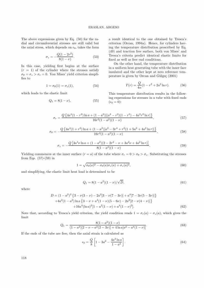
For a tube of inner radius a = 0.5 with freeends, the elastic limit heat load, as given in Table1, is Q1 = 11.641. The stresses and displacement atthis load are calculated and plotted in Figure 1(b).Again, numerical and analytical solutions agree per-fectly. Furthermore, it is evident from this figurethat φ = 1 at the outer surface pointing the locationof formation of plastic deformation. These samplecalculations reveal that the numerical solution algo-rithm performs very well and that the computer codethat implements this algorithm is functioning prop-erly.
Results and Discussion
Before the results of nonlinear hardening structuresare presented, comparisons will be made with pub-lished analytical solutions based on Tresca’s yieldcriterion. The stresses in a uniform heat generating,elastic ideally plastic cylinder with free ends were cal-culated by Orcan (1994a). Since the present modelis not specifically designed for ideally plastic materi-als, it is impossible to take H = 0 exactly for compu-tational reasons. However, material behavior of thistype may be simulated by assigning m = 1 and usingsufficiently small H . Using the parameters of Orcan(1994a), Q = 16.2, ν = 0.295 and also m = 1 andH = 10−5, the corresponding stresses, displacementand plastic strains are computed. Figures 2(a) and(b) show the results of this computation (solid lines)in comparison to those of Orcan (1994a) (dots). Thestresses and displacement, as shown in Figure 2(a),compare well. Conversely, as seen in Figure 2(b),the comparison concerning the plastic strains is poor.The fact that the cylinder is composed of 3 regions,an inner plastic, an elastic and an outer plastic isevident from Figure 2(a), through a look at the vari-ation of φ. In addition φ = 1 in both plastic regionsis the result of nonhardening behavior of material.
Another analytical solution for an ideally plasticmaterial was derived by Orcan and Gulgec (2001)for a tube with free ends using the temperature dis-tribution given by Eq. (56). The results of the cal-culations are compared with their solution for thestresses and displacement in Figure 3(a) and plasticstrains in Figure 3(b). Again, dots represent the an-alytical solution. The parameters used are a = 0.2,Q = 20.0, ν = 0.295, H = 10−5. In contrast to thefree end cylinder solution, the agreement between 2solutions as to plastic strains is satisfactory.
-2.5
-2.0
-1.5
-1.0
-0.5
0.0
0.5
1.0
1.5
2.0
2.5
0.0 0.2 0.4 0.6 0.8 1.0
radial coordinate
stre
sses
an
d d
isp
lace
men
t φ
rσ
θσ
zσ
u
(a)
-3.0
-2.5
-2.0
-1.5
-1.0
-0.5
0.0
0.5
1.0
1.5
2.0
0.0 0.2 0.4 0.6 0.8 1.0
radial coordinate
pla
stic
str
ain
s
p
rε
p
θε
p
zε5×prε
5×pθε
5×pzε
(b)
Figure 2. (a) Stresses and displacement, (b) plasticstrains in elastic ideally plastic cylinder withfree ends at Q = 16.2. Dots represent the ana-lytical solution of Orcan (1994a).
120

ERASLAN, ARGESO
-2.0
-1.5
-1.0
-0.5
0.0
0.5
1.0
1.5
2.0
2.5
0.2 0.4 0.6 0.8 1.0
radial coordinate
stre
sses
an
d d
isp
lace
men
t
rσ
θσ
zσ
φ
u
(a)
-3.5
-2.5
-1.5
-0.5
0.5
1.5
2.5
0.2 0.4 0.6 0.8 1.0
radial coordinate
pla
stic
str
ain
s
p
rε
p
rε
p
θε
p
θε
p
zε
p
zε
(b)
Figure 3. (a) Stresses and displacement, (b) plasticstrains in elastic ideally plastic tube with freeends at Q = 20. Dots represent the analyticalsolution of Orcan and Gulgec (2001).
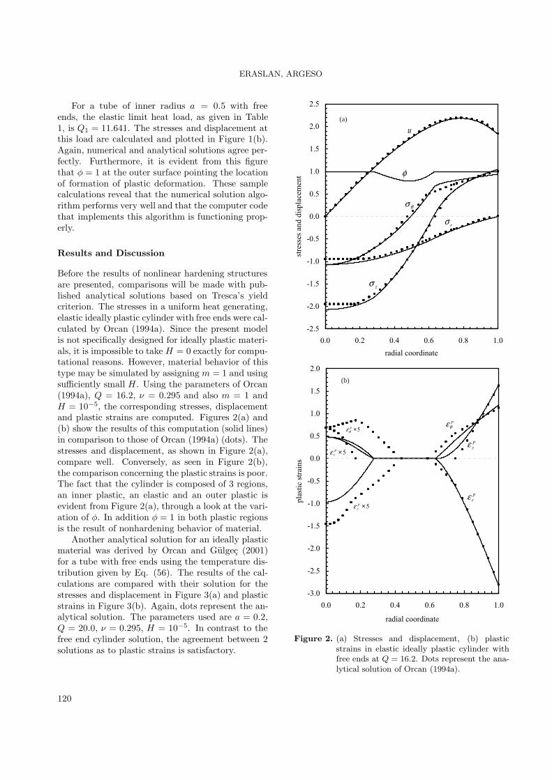
The thermoplastic response of a linear strainhardening cylinder with fixed ends was studied bySener and Eraslan (2003). All stages of elastic-plastic deformation were treated analytically, frompurely elastic to fully plastic, by Sener and Eraslan(2003), employing the temperature field (49). Tak-ing Q = 5.6054, ν = 0.295, m = 1 and H = 0.25the stresses and displacement are calculated andcompared with the analytical result from Sener andEraslan (2003) in Figure 4(a). Moreover, the propa-gation of the elastic-plastic border with the increas-ing values of heat load is also calculated and theresult is plotted in Figure 4(b). The dots belong tothe analytical result of Sener and Eraslan (2003). Asseen in this figure, plastic deformation commences atthe center of the cylinder at Q = 4.6667 (see Table1) and propagates toward the surface as the heatload is increased. When the heat load reaches an-other critical value, Qs, a second plastic region de-velops at the surface. The present model predictsQs = 6.2795, while the analytical finding is 5.6103.Moreover, the cylinder becomes just fully plastic atQfp = 6.9773, though Qfp = 6.8412 is reported inSener and Eraslan (2003), based on the analytical so-lution. Figure 4(b) also shows that the elastic-plasticborder advances more rapidly by Tresca’s criterionthan by that of von Mises’, and hence more conser-vative limit heat loads are predicted.
The work of Orcan (1994a) was recently extendedto linear hardening by Sener (2003). A final com-parison is made with the results of Sener (2003).These comparisons are shown in Figures 5(a) and(b). Model predictions for the stresses and dis-placement corresponding to the parameters Q = 10,ν = 0.295, m = 1 and H = 0.25 are compared tothose of Sener (2003) in Figure 5(a), and for the plas-tic strains in 5(b). This comparison and the ones dis-cussed above verify the present elastoplastic modelon a different class of problems and for a wide rangeof values of parameters.
To give an example regarding nonlinearly harden-ing thermal stress calculation, we consider a uniformheat generating cylinder with fixed ends. The defor-mation behavior of this cylinder has been explainedabove with reference to the analytical work of Or-caw (1994) and temperature distribution (49). Thecylinder with fixed ends becomes partially plastic forthe loads Q > 4.6667. Taking ν = 0.3, H = 0.4 andm = 0.5, and assigning Q = 6.85, the elastic-plasticstresses and displacement in a nonlinearly hardeningcylinder are computed and plotted
121
ERASLAN, ARGESO
-1.6
-1.2
-0.8
-0.4
0.0
0.4
0.8
1.2
0.0 0.2 0.4 0.6 0.8 1.0
radial coordinate
stre
sses
an
d d
isp
lace
men
t
rσ
θσ
zσ
u
φ
(a)
4.0
4.5
5.0
5.5
6.0
6.5
7.0
7.5
0.0 0.2 0.4 0.6 0.8 1.0
border radius
hea
t lo
ad
(b)
Figure 4. (a) Stresses and displacement at Q = 5.6054,(b) propagation of elastic-plastic border radiusin a linearly hardening cylinder with fixed ends.Dots represent the analytical solution of Senerand Eraslan (2003).
-2.0
-1.6
-1.2
-0.8
-0.4
0.0
0.4
0.8
1.2
1.6
0.0 0.2 0.4 0.6 0.8 1.0
radial coordinate
stre
sses
an
d d
isp
lace
men
t
φφ
u
rσθσ
zσ
(a)
-1.0
-0.8
-0.6
-0.4
-0.2
0.0
0.2
0.4
0.6
0.7 0.8 0.9 1.0
radial coordinate
pla
stic
str
ain
s
p
rε
p
θε
p
zε
(b)
Figure 5. (a) Stresses and displacement, (b) plasticstrains in a linearly hardening cylinder withfree ends at Q = 10. Dots represent the ana-lytical solution of Sener (2003).
122

ERASLAN, ARGESO
-2.0
-1.5
-1.0
-0.5
0.0
0.5
1.0
1.5
0.0 0.2 0.4 0.6 0.8 1.0
radial coordinate
stre
sses
an
d d
isp
lace
men
t
θσ
rσ
zσ
φ
u
epr epr
Figure 6. Stresses and displacement in a nonlinearlyhardening cylinder with fixed ends at Q = 6.85.
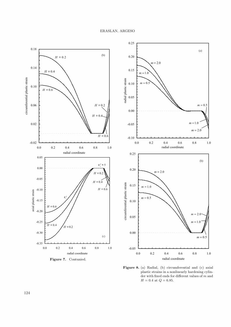
in Figure 6. Under this load, the cylinder is com-posed of 3 different regions: an inner plastic re-gion in 0 ≤ r ≤ 0.74169, an elastic region in0.74169 ≤ r ≤ 0.90811 and an outer plastic region in0.90811 ≤ r ≤ 1. An elastic-plastic border in Figure6 is designated by the symbol rep. Additional runsare performed for this system to investigate the effectof material parameters H and m on plastic strains.The results of these calculations are depicted in Fig-ures 7 and 8. In both, ν = 0.3 and Q = 6.85. Figure7 exemplifies the effect of the hardening parameterH on plastic strains corresponding to m = 0.5, whileFigure 8 demonstrates the effect of m correspondingto H = 0.4. As seen in these figures, both parame-ters affect plastic strains significantly and there arecorrespondingly larger plastic strains for smaller val-ues of H and larger values of m. It is also seen thatthe widths of inner and outer plastic zones are bothnotably affected by the change in either H or m.The propagation of an elastic plastic border with in-creasing values of heat load is shown in Figure 9. InFigure 9(a), H is kept constant at 0.4 and m is usedas a parameter. As seen in this figure, the fully plas-tic limit heat load Qfp increases in the direction ofdecreasing m. The hardening parameter H is used
as a parameter for m = 0.5 in Figure 9(b). As seenin Figure 9, the effect of parameters H and m onthe propagation of elastic-plastic interface becomessignificant as the fully plastic limit is approached.
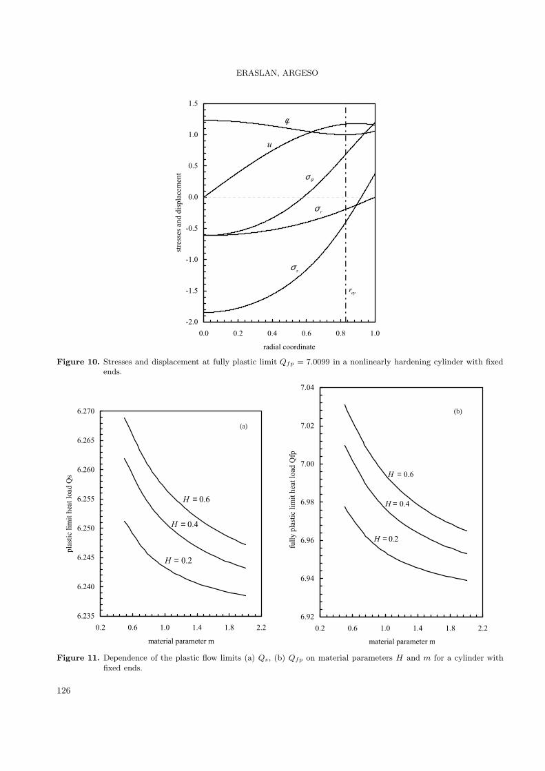
The fully plastic limit of the cylinder with fixedends corresponding to the values of parameters ν =0.3, H = 0.4, m = 0.5 is calculated as Qfp = 7.0099.The stresses and displacement at this limit heat loadare presented in Figure 10. The elastic region shrinksto a surface at r = rep where both plastic regions joineach other. A parametric analysis is carried out toinvestigate the effect of material parameters H andm on the plastic limit heat load Qs as well as on thefully plastic limit heat load Qfp. Note again that,Qs is the critical load at which plastic deformationsets in at the free surface. Figure 11 shows the re-sult of this analysis. Variation of Qs with m usingH as a parameter is plotted in Figure 11(a) whereasvariation of Qfp is plotted in Figure 11(b). As seenin these figures, although both Qs and Qfp increasewith increasing H and decreasing m, these effects aremore pronounced on the fully plastic limit Qfp.
-0.10
-0.05
0.00
0.05
0.10
0.15
0.20
0.0 0.2 0.4 0.6 0.8 1.0
radial coordinate
rad
ial
pla
stic
str
ain
2.0=H
4.0=H
6.0=H
2.0=H
4.0=H
6.0=H
(a)
Figure 7. (a) Radial, (b) circumferential and (c) axialplastic strains in a nonlinearly hardening cylin-der with fixed ends for different values of H andm = 0.5 at Q = 6.85.
123
ERASLAN, ARGESO
-0.02
0.02
0.06
0.10
0.14
0.18
0.0 0.2 0.4 0.6 0.8 1.0
radial coordinate
circ
um
fere
nti
al p
last
ic s
trai
n
2.0=H
4.0=H
6.0=H
2.0=H
4.0=H
6.0=H
(b)
-0.35
-0.30
-0.25
-0.20
-0.15
-0.10
-0.05
0.00
0.05
0.0 0.2 0.4 0.6 0.8 1.0
radial coordinate
axial plastic strain
p
zε
5×ε p
z
2.0=H4.0=H
6.0=H
2.0=H
4.0=H
6.0=H
(c)
Figure 7. Contunied.
-0.10
-0.05
0.00
0.05
0.10
0.15
0.20
0.25
0.0 0.2 0.4 0.6 0.8 1.0
radial coordinate
rad
ial
pla
stic
str
ain
5.0=m
0.1=m
0.2=m
5.0=m
0.1=m
0.2=m
(a)
-0.05
0.00
0.05
0.10
0.15
0.20
0.25
0.0 0.2 0.4 0.6 0.8 1.0
radial coordinate
circ
um
fere
nti
al p
last
ic s
trai
n
5.0=m
0.1=m
0.2=m
5.0=m
0.1=m
0.2=m
(b)
Figure 8. (a) Radial, (b) circumferential and (c) axialplastic strains in a nonlinearly hardening cylin-der with fixed ends for different values of m andH = 0.4 at Q = 6.85.
124

ERASLAN, ARGESO
-0.45
-0.40
-0.35
-0.30
-0.25
-0.20
-0.15
-0.10
-0.05
0.00
0.05
0.0 0.2 0.4 0.6 0.8 1.0
radial coordinate
axia
l p
last
ic s
trai
n
p
zε
5×ε pz
5.0=m
0.1=m
0.2=m
5.0=m
0.1=m
0.2=m
(c)
Figure 8. Contunied.
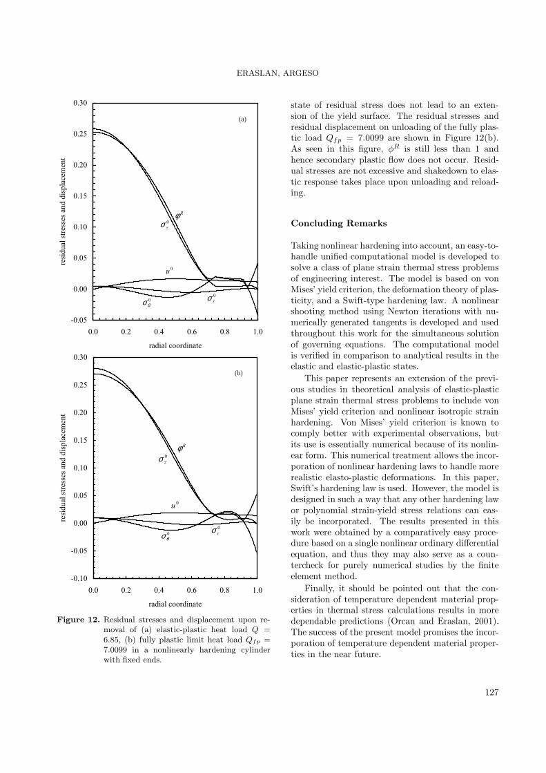
In engineering applications, the system is sub-jected to repeated stress cycles by loading and un-loading. The residual stresses occurring during theunloading process and the possibility of alternatingthe plastic response of the system is also investigated.To this end, the residual stresses due to complete un-loading of the thermal load Q = 6.85 (Figure 6) arecalculated by subtracting the stresses and displace-ment corresponding to unrestricted elastic behaviorfrom elastic-plastic ones at the same load parameter.Of course, this calculation procedure holds true onlywhen the residual stresses do not exceed the yieldlimit (Orcan, 1994b). Residual stresses and displace-ment are plotted in Figure 12(a). In this figure, thenondimensional stress components are designated byσ0j and displacement by u0 to imply stand-still. The
stress variable φR is calculated from Eq. (67) withσj replaced by σ0
j . Since φR < 1, unloading occurselastically and reversed plastic flow (secondary plas-tic flow) does not take place. The residual plasticstrains are not altered and are as given in Figure 7.The axial stress is again maximum at the axis, butthis time it is tensile. Upon reloading, superpositionof the stresses due to the applied thermal load on the
4.4
4.8
5.2
5.6
6.0
6.4
6.8
7.2
0.0 0.2 0.4 0.6 0.8 1.0
border radius
hea
t lo
ad
5.0=m0.1=m
0.2=m
(a)
4.4
4.8
5.2
5.6
6.0
6.4
6.8
7.2
0.0 0.2 0.4 0.6 0.8 1.0
border radius
heat load
2.0=H
(b)
H = 0.4 H = 0.6
Figure 9. Propagation of elastic-plastic border radius for(a) different values of m and H = 0.4, (b) fordifferent values of H and m = 0.5 in a nonlin-early hardening cylinder with fixed ends.
125
ERASLAN, ARGESO
-2.0
-1.5
-1.0
-0.5
0.0
0.5
1.0
1.5
0.0 0.2 0.4 0.6 0.8 1.0
radial coordinate
stre
sses
an
d d
isp
lace
men
t θσ
rσ
zσ
φ
u
epr
Figure 10. Stresses and displacement at fully plastic limit Qfp = 7.0099 in a nonlinearly hardening cylinder with fixedends.
6.235
6.240
6.245
6.250
6.255
6.260
6.265
6.270
0.2 0.6 1.0 1.4 1.8 2.2
material parameter m
plastic limit heat load Qs
2.0=H
4.0=H
6.0=H
(a)
6.92
6.94
6.96
6.98
7.00
7.02
7.04
0.2 0.6 1.0 1.4 1.8 2.2
material parameter m
full
y p
last
ic l
imit
hea
t lo
ad Q
fp
2.0=H
4.0=H
6.0=H
(b)
Figure 11. Dependence of the plastic flow limits (a) Qs, (b) Qfp on material parameters H and m for a cylinder withfixed ends.
126
ERASLAN, ARGESO
-0.05
0.00
0.05
0.10
0.15
0.20
0.25
0.30
0.0 0.2 0.4 0.6 0.8 1.0
radial coordinate
resi
du
al s
tres
ses
and
dis
pla
cem
ent
Rφ
0
rσ0
θσ
0
zσ
0u
(a)
-0.10
-0.05
0.00
0.05
0.10
0.15
0.20
0.25
0.30
0.0 0.2 0.4 0.6 0.8 1.0
radial coordinate
resi
du
al s
tres
ses
and
dis
pla
cem
ent
Rφ
0
rσ0
θσ
0
zσ
0u
(b)
Figure 12. Residual stresses and displacement upon re-moval of (a) elastic-plastic heat load Q =6.85, (b) fully plastic limit heat load Qfp =7.0099 in a nonlinearly hardening cylinderwith fixed ends.
state of residual stress does not lead to an exten-sion of the yield surface. The residual stresses andresidual displacement on unloading of the fully plas-tic load Qfp = 7.0099 are shown in Figure 12(b).As seen in this figure, φR is still less than 1 andhence secondary plastic flow does not occur. Resid-ual stresses are not excessive and shakedown to elas-tic response takes place upon unloading and reload-ing.
Concluding Remarks
Taking nonlinear hardening into account, an easy-to-handle unified computational model is developed tosolve a class of plane strain thermal stress problemsof engineering interest. The model is based on vonMises’ yield criterion, the deformation theory of plas-ticity, and a Swift-type hardening law. A nonlinearshooting method using Newton iterations with nu-merically generated tangents is developed and usedthroughout this work for the simultaneous solutionof governing equations. The computational modelis verified in comparison to analytical results in theelastic and elastic-plastic states.
This paper represents an extension of the previ-ous studies in theoretical analysis of elastic-plasticplane strain thermal stress problems to include vonMises’ yield criterion and nonlinear isotropic strainhardening. Von Mises’ yield criterion is known tocomply better with experimental observations, butits use is essentially numerical because of its nonlin-ear form. This numerical treatment allows the incor-poration of nonlinear hardening laws to handle morerealistic elasto-plastic deformations. In this paper,Swift’s hardening law is used. However, the model isdesigned in such a way that any other hardening lawor polynomial strain-yield stress relations can eas-ily be incorporated. The results presented in thiswork were obtained by a comparatively easy proce-dure based on a single nonlinear ordinary differentialequation, and thus they may also serve as a coun-tercheck for purely numerical studies by the finiteelement method.
Finally, it should be pointed out that the con-sideration of temperature dependent material prop-erties in thermal stress calculations results in moredependable predictions (Orcan and Eraslan, 2001).The success of the present model promises the incor-poration of temperature dependent material proper-ties in the near future.
127

ERASLAN, ARGESO
References
Boley, B.A. and Weiner, J.Fr., Theory of ThermalStresses, Wiley, New York, 1960.
Eraslan, A.N., “Thermally Induced Deformationsof Elastic-Plastic Composite Tubes Subjected toa Nonuniform Heat Source”. Journal of ThermalStresses 26, 167-193, 2003.
Eraslan, A.N. and Orcan, Y., “Thermoplastic Re-sponse of a Linearly Hardening Cylinder Subjectedto Nonuniform Heat Source and Convective Bound-ary Condition”. Mechanics Based Design of Struc-tures and Machines 32, 133-164, 2004.
Eraslan, A.N., Sener, E. and Argeso H., “Stress Dis-tributions in Energy Generating Two-Layer TubesSubjected to Free and Radially Constrained Bound-ary Conditions”. International Journal of Mechani-cal Sciences 45, 469-496, 2003.
Gulgec, M. and Orcan, Y., “On the Elastic-PlasticDeformation of a Centrally Heated Cylinder Ex-hibiting Linear Hardening”. Journal of AppliedMathematics and Mechanics (ZAMM) 79, 493-498,1999.
Hindmarsh, A.C., ODEPACK: A Systematized Col-lection of ODE Solvers. In: Scientific Computing,(Stepleman, R.S., ed.) North Holland, Amsterdam,1983.
Orcan, Y. and Gamer, U., “Elastic-Plastic Defor-mation of a Centrally Heated Cylinder”. Acta Me-chanica 90, 61-80, 1991.
Orcan, Y., “Thermal Stresses in a Heat GeneratingElastic-Plastic Cylinder with Free Ends”. Interna-
tional Journal of Engineering Science 32, 883-898,1994a.
Orcan, Y., “Residual Stresses and Secondary PlasticFlow in a Heat Generating Elastic-Plastic Cylinderwith Free Ends”. International Journal of Engineer-ing Science 33, 1689-1698, 1994b.
Orcan, Y. and Eraslan, A.N., “Thermal Stresses inElastic-Plastic Tubes with Temperature-DependentMechanical and Thermal Properties”. Journal ofThermal Stresses 24, 1097-1113, 2001.
Orcan, Y. and Gulgec, M., “Elastic-Plastic Defor-mation of a Tube with Free Ends Subjected to In-ternal Heat Generation”. Turkish Journal of Engi-neering and Environmental Sciences 25, 1-10, 2001.
Sener, E., Thermal Stresses in a Heat GeneratingLinearly Hardening Cylinder with Free Ends, MScThesis. Department of Engineering Sciences, MiddleEast Technical University, Ankara, Turkey, 2003.
Sener, E. and Eraslan, A.N., (in Turkish) “Li-neer Olarak Peklesebilen Ucları Sabit Bir SilindirinTermo-Elasto-Plastik Analitik Cozumu”. Proceed-ings of the 13th National Congress on Mechanics,Gaziantep, Turkey, 727-736, 2003.
Ugural, A.C. and Fenster, S.K., Advanced Strengthand Applied Elasticity, 3rd ed., Prentice-Hall, Lon-don, 1995.
Timoshenko, S. and Goodier, J.N., Theory of Elas-ticity, 3rd ed., McGraw-Hill, New York, 1970.
128


![monotonous [muh- not -n-uhs] ( adj .)](https://img.pdfslide.us/doc/110x75/56815754550346895dc4fb9e/monotonous-muh-not-n-uhs-adj-.jpg)