Embed Size (px)
Citation preview

On the Appearance of Translucent Edges
Ioannis GkioulekasHarvard SEAS
Bruce WalterCornell University
Edward H. AdelsonMassachusetts Institute of Technology
Kavita BalaCornell [email protected]
Todd ZicklerHarvard SEAS
Abstract
Edges in images of translucent objects are very differentfrom edges in images of opaque objects. The physicalcauses for these differences are hard to characterize ana-lytically and are not well understood. This paper consid-ers one class of translucency edges—those caused by a dis-continuity in surface orientation—and describes the physi-cal causes of their appearance. We simulate thousands oftranslucency edge profiles using many different scatteringmaterial parameters, and we explain the resulting variety ofedge patterns by qualitatively analyzing light transport. Wealso discuss the existence of shape and material metamers,or combinations of distinct shape or material parametersthat generate the same edge profile. This knowledge is rel-evant to visual inference tasks that involve translucent ob-jects, such as shape or material estimation.
1. Introduction
Translucency is a common visual phenomenon. It occurswhenever light penetrates a material and scatters within itbefore re-emerging toward the observer. This internal scat-tering can create a variety of image effects, depending on anobject’s shape and material; its distance from the observer;and the composition of the lighting around it. Common hu-man experience suggests that these image effects containuseful material information, and there is psychophysical ev-idence that humans can discriminate subtle differences intranslucent appearance, recognize translucent material cat-egories, and make inferences about physical scattering pa-rameters [2, 11, 13, 27].
There ought to be specific patterns of image brightness, ortheir statistics, that constrain the set of plausible shapes andmaterials in an image of translucency. If we understoodthese patterns, we could use them to develop inference al-gorithms, analogous to those that exist for opaque scenes.
Figure 1: Radiance profiles at a discontinuity in orientation.The wedge configuration is a horizontal cross-section of twoplanar faces that meet in a vertical line. Here it is lit fromthe left. If the material were opaque (as below) the profilewould be a step edge. When it is translucent (as above), theprofiles can be very different, often with multiple extremathat are displaced from the discontinuity.
One prominent class of brightness patterns is edges, orsharp local changes in image brightness. Edges have a va-riety of causes—cast shadows, material boundaries, occlu-sions, etc.—and models of edges play prominent roles ina variety of inference algorithms, including contour detec-tion, deblurring, and material recognition. In this paper, wefocus on edges that are caused by a discontinuous changein surface orientation, such as at the corners of the cubes inFigure 1. Locally, this geometry can be modeled by the one-dimensional wedge of Figure 2. We use this as an archetypalconfiguration for studying edges of translucency.
The radiance profile observed from an opaque wedge wouldbe the familiar step function, which is a popular edge modelin image processing and computer vision. But the radianceprofiles for translucent wedges are very different. As shownin Figure 1, they tend to exhibit multiple extrema in thevicinity of an orientation discontinuity, and these extremaare often displaced away from the geometric discontinuity.
The physical causes of these profile phenomena are not wellunderstood. One reason is that they are hard to describe
intensity
positionposition
θl
θw
θv
Figure 2: Left: Wedge model. A homogeneous translu-cent volume forms a perfect corner with internal angle θw,and this corner is lit from the side (direction θl) and viewedfrom above (direction θv). Right: A typical radiance profilemeasured by the camera. It is the sum of an interface com-ponent and an internal scattering component. We consideronly the scattering component in the rest of this paper.
analytically. For the translucent wedge configuration, radi-ance profiles represent the combination of interface reflec-tion with various orders of volume scattering events. Theyresult from interactions between view and light directions,refractive index, optical density, scattering albedo, and scat-tering phase function. There is unlikely to be an analyticsolution to the radiative transport equation for this scenario,and we have yet to find a useful approximate solution.
Our strategy is to explore these phenomena empiricallythrough simulation. Using Monte Carlo rendering tech-niques, we generate a database of thousands of radianceprofiles for many scattering materials and wedge configura-tions. We catalog the variety of profiles we observe, and wequalitatively explain their features by analyzing light trans-port in terms of interface events, single-scattering, mid-order scattering, and high-order scattering (diffusion). Wealso discuss the existence of shape and material metamers—combinations of distinct shape or material parameters thatnonetheless generate the same radiance profile.
Together, our analyses provide a comprehensive descriptionof the physical causes of the radiance profiles that are in-duced by surface orientation discontinuities, or geometricedges, on translucent materials. This is a foundation forunderstanding how these profiles can be used for visual in-ference tasks, where we want to estimate shape and materialinformation from images that include translucency.
2. Scattering near an orientation discontinuity
We consider a wedge with a perfectly sharp corner, madeof a single, homogeneous translucent material. A two-dimensional cross-section of this scene is shown in Figure 2.The wedge is illuminated from the side by collimated light,and is imaged from above by an orthographic camera. Thisgeometry has three degrees of freedom: the illuminationand view directions θl, θv , and the wedge angle θw.
The radiance profile measured by the camera is the sum oftwo components, as shown in Figure 2. The first is an inter-face component, which corresponds to light that is reflectedat the wedge surface, without entering the material volume.We assume the interface is smooth, so this component is de-termined by the index of refraction η and the light and viewangles θl, θv , as described by the Fresnel equations. Theinterface component has the familiar shape of a step func-tion, with the step occurring exactly at the image-projectionof the orientation discontinuity. Since it does not dependon scattering, does not create an interesting variety of ra-diance profiles, and has been well-studied elsewhere, weignore this component for the remainder of the paper. How-ever, one should keep in mind that this step-shaped interfacecomponent will dominate whenever the view and illumina-tion directions are close to being mirrored.
The second component of the radiance profile correspondsto light that is refracted at the interface and travels insidethe volume. There, it experiences scattering and internal re-flection, perhaps many times, before traversing the interfaceagain toward the camera. We call this the scattering compo-nent. The refraction and internal reflection at the material-air interfaces are modeled by the Fresnel equations and in-volve a single material parameter, the index of refractionη. Scattering occurs as light propagates through the mate-rial medium and interacts with material structures. This re-sults in multiple volume events that each cause absorptionor change of propagation direction.
Scattering is governed by three material parameters that ap-pear in the radiative transfer equation [6, 16]: the density(extinction coefficient) σt; the scattering albedo α; and thescattering phase function p(θ), θ ∈ [0, π). Density σt con-trols the spatial frequency of volume events. Albedo α ≤ 1is a probability controlling whether light at a volume eventis scattered (Pr = α) or absorbed (Pr = 1 − α). Finally,phase function p is a probability distribution function on thesphere of directions that describes the angular distributionof light scattered at volume events. As is usual, we assumethe phase function is cylindrically-symmetric and invariantto rotations of the incident direction, so it only depends onangle θ relative to the incident direction.
To study the appearance of the scattering component ofthe radiance profiles, we use Monte Carlo rendering forthe full (three-dimensional) wedge scene to generate radi-ance profiles for different combinations of geometry andmaterial parameters. For geometry, we consider illumi-nation and view directions ranging from grazing to al-most normal incidence, excluding larger angles to pre-vent illumination of the right surface and ensure that bothsurfaces are visible: θv, θl ∈ {15◦, 30◦, 45◦, 60◦, 75◦},and θw ∈ {30◦, 60◦, 90◦}. For materials, we focus onnon-emissive, low-absorption dielectrics, which include a
+regio
n 2
region 1 region 4
=
single scattering
mid-order scattering
high-order scattering
+
regio
n 3
xmin xmax
Imin
Imax
Iasymptote
full profile
inte
nsi
ty
position
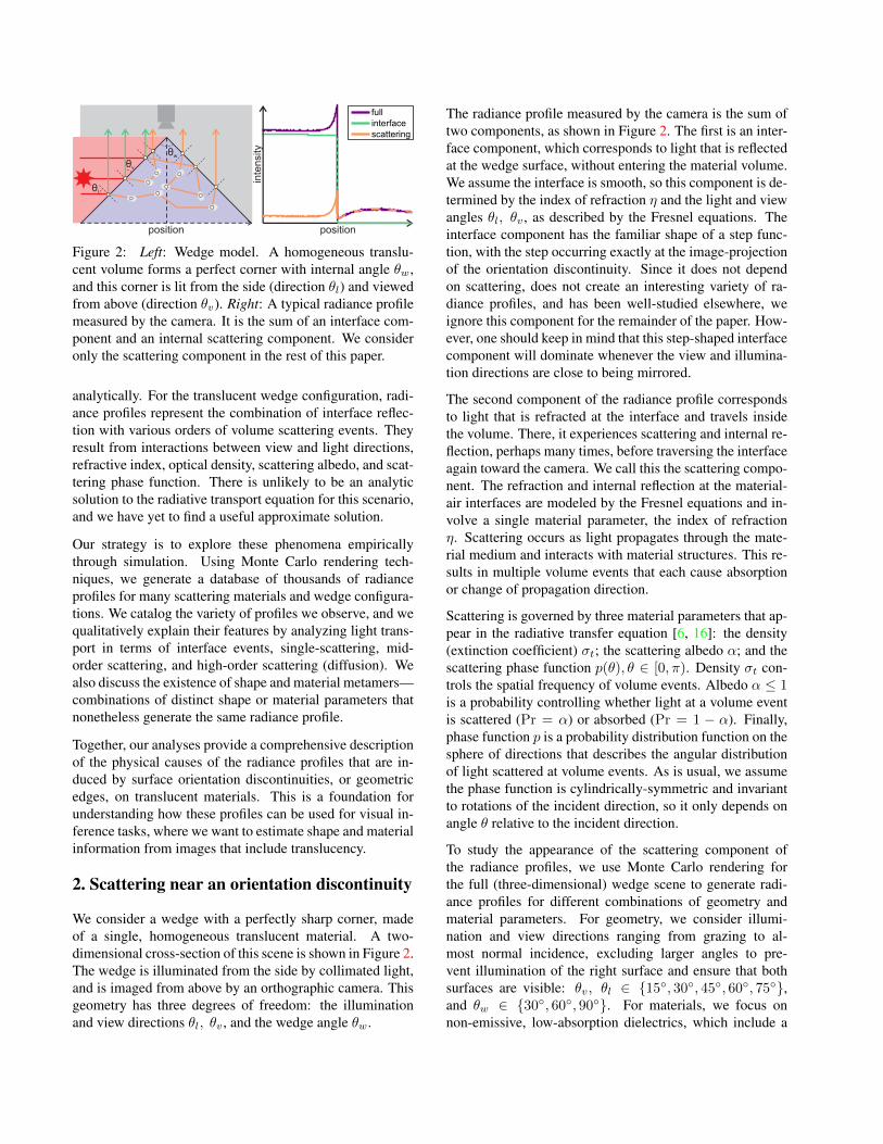
Figure 3: Left: Representative edge radiance profile fora translucent material. A profile is typically made up offour qualitatively distinct regions, highlighted with differ-ent background colors. These give rise to characteristicfeatures, in the form of local radiance extrema away fromthe geometric edge, as shown. Right: Decomposition ofthe profile into single, mid-order, and high-order scatteringcomponents. Different subsets of the four qualitative re-gions of the full profile appear in the three scattering com-ponents, indicated by matching colors.
wide range of common translucent materials such as soapand wax, and exclude near-transparent absorptive liquids.Specifically, we use: η ∈ {1.3, 1.4, 1.5, 1.6, 1.7, 1.8},α ∈ {0.9, 0.92, 0.94, 0.96, 0.98, 1}, and a phase functiondictionary consisting of linear combinations of Henyey-Greenstein and von Mises-Fisher lobes [13]. We use densityσt = 1mm−1 and a field of view (length of “position” axis)of approximately one inch. We note that these values are ar-bitrary, due to a scale ambiguity between density and fieldof view: doubling the density and halving the (linear) fieldof view has no effect on the radiance profile. The databaseis available at the project page [1], and we use it, along withthe corresponding parameter ranges, throughout the rest ofthe paper. Section 4 discusses additional renderings forwedge scenes with various non-idealities. Finally, we haveproduced additional renderings using Lorentz-Mie [12] andmeasured [14] phase functions, to validate that our findingsare not biased by our dictionary selection.
3. Behavior of Radiance Profiles
A typical translucent edge profile, as shown in Figure 3, hasfour basic regions. These are highlighted in the figure usingdifferent background colors. Starting from the left (illumi-nated side) in region 1, radiance decreases from a steadyvalue to a local minimum at some location xmin. Then itincreases sharply in region 2, before making a discontin-uous jump at the projection of the wedge’s apex. It risesagain in region 3, eventually reaching a local maximum atsome xmax. In region 4, it decreases monotonically to zero.These qualitative features are characteristic of translucency
because they are distinct from the sigmoidal edge profilesof opaque materials. As we will describe later, the localextrema that are displaced from the geometric discontinuityare particularly characteristic, since they appear even whenthe geometry deviates from the ideal wedge shape (Fig-ure 7). These features could be used to distinguish translu-cent materials from opaque ones.
To understand the physical processes that produce thesecharacteristic features, it is helpful to separately examinetwo limit scattering components: light that has only scat-tered once (single scattering) and light that has scatteredmany times (high-order scattering).
3.1. Single Scattering
The radiance profile from just the single-scattering compo-nent of the light transport is shown in Figure 3. Its expres-sion can be easily derived analytically, though it is more in-tuitive to describe it qualitatively in two steps. First, we de-scribe the zero-scattering lightfield inside the material vol-ume. Then, we trace view rays through this lightfield toproduce a radiance profile. We use Figure 4 for reference.
Consider a light ray l (shown in red) entering from the leftside of the wedge. It first gets refracted at point q1 of the air-material interface. Then, the ray propagates straight insidethe medium, while also being attenuated due to absorptionand outscatter. After the ray reaches the right edge, at pointq2, it gets reflected internally, either partially or totally, de-pending on whether the angle of incidence is larger than thecritical angle for the volume’s index of refraction. The raythen propagates in the reflected direction.
This process produces a total zero-scattering lightfield thatis the sum of two components. The first is light that hasnot undergone internal reflection (the light ray l betweenpoints q1 and q2). It extends everywhere inside the wedgevolume, and at any point radiance is non-zero along a sin-gle direction. The second component corresponds to lightthat is internally reflected (the light ray l after point q2), andextends spatially only in the part of the wedge volume thatis reached by reflected rays. This area is bounded from theleft by a line parallel to the reflected rays and starting at theapex of the wedge, as shown in Figure 4. We refer to thisline as the internal reflection boundary, and we visualize itas a dotted black line inside the wedge. The reflected light-field component is also non-zero along a single direction.The superposition of these two components results in a totalzero-scattering lightfield that has two distinct regions, withthe region right of the internal reflection boundary having ahigher total flux (the sum of radiance in all directions) thanthe region left of it, as shown in Figure 4.
To relate the zero-scattering lightfield to the single-scattering radiance profile, we trace view rays that start from
inte
nsi
ty
positionl
q1
q2
v1v2 v3 v4
p1
p2
p3
p4
low-flux area
high-flux area
0
1
flux
v2
v1 v3 v4
l
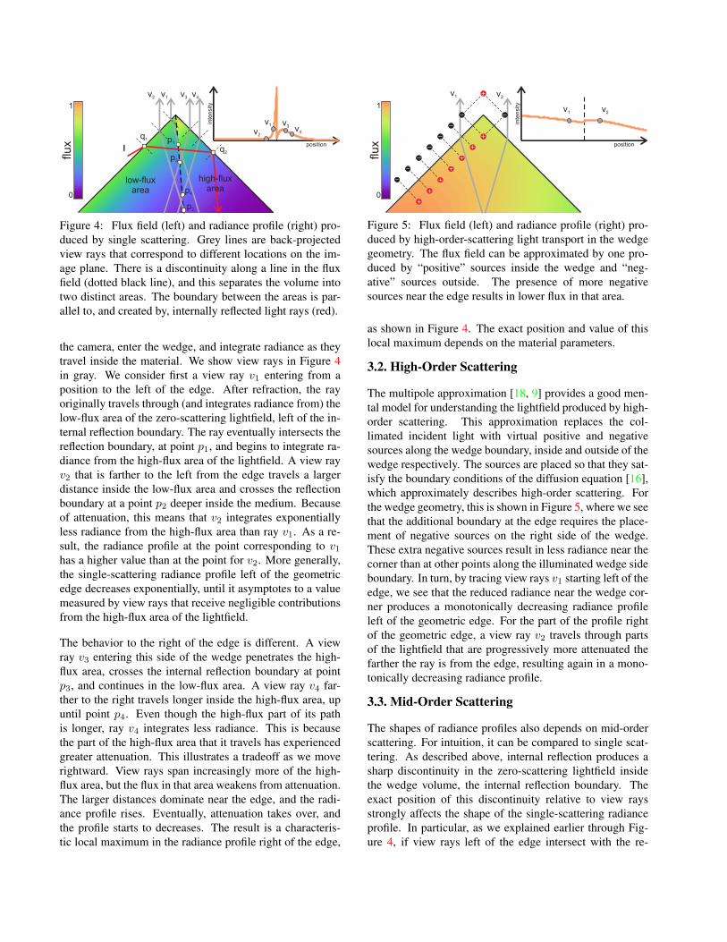
Figure 4: Flux field (left) and radiance profile (right) pro-duced by single scattering. Grey lines are back-projectedview rays that correspond to different locations on the im-age plane. There is a discontinuity along a line in the fluxfield (dotted black line), and this separates the volume intotwo distinct areas. The boundary between the areas is par-allel to, and created by, internally reflected light rays (red).
the camera, enter the wedge, and integrate radiance as theytravel inside the material. We show view rays in Figure 4in gray. We consider first a view ray v1 entering from aposition to the left of the edge. After refraction, the rayoriginally travels through (and integrates radiance from) thelow-flux area of the zero-scattering lightfield, left of the in-ternal reflection boundary. The ray eventually intersects thereflection boundary, at point p1, and begins to integrate ra-diance from the high-flux area of the lightfield. A view rayv2 that is farther to the left from the edge travels a largerdistance inside the low-flux area and crosses the reflectionboundary at a point p2 deeper inside the medium. Becauseof attenuation, this means that v2 integrates exponentiallyless radiance from the high-flux area than ray v1. As a re-sult, the radiance profile at the point corresponding to v1has a higher value than at the point for v2. More generally,the single-scattering radiance profile left of the geometricedge decreases exponentially, until it asymptotes to a valuemeasured by view rays that receive negligible contributionsfrom the high-flux area of the lightfield.
The behavior to the right of the edge is different. A viewray v3 entering this side of the wedge penetrates the high-flux area, crosses the internal reflection boundary at pointp3, and continues in the low-flux area. A view ray v4 far-ther to the right travels longer inside the high-flux area, upuntil point p4. Even though the high-flux part of its pathis longer, ray v4 integrates less radiance. This is becausethe part of the high-flux area that it travels has experiencedgreater attenuation. This illustrates a tradeoff as we moverightward. View rays span increasingly more of the high-flux area, but the flux in that area weakens from attenuation.The larger distances dominate near the edge, and the radi-ance profile rises. Eventually, attenuation takes over, andthe profile starts to decreases. The result is a characteris-tic local maximum in the radiance profile right of the edge,
0
1
flux
intensity
position
v2
v1 v2
v1
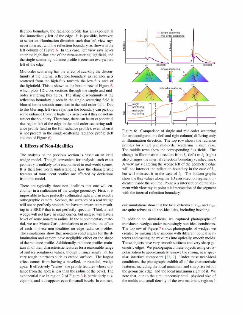
Figure 5: Flux field (left) and radiance profile (right) pro-duced by high-order-scattering light transport in the wedgegeometry. The flux field can be approximated by one pro-duced by “positive” sources inside the wedge and “neg-ative” sources outside. The presence of more negativesources near the edge results in lower flux in that area.
as shown in Figure 4. The exact position and value of thislocal maximum depends on the material parameters.
3.2. High-Order Scattering
The multipole approximation [18, 9] provides a good men-tal model for understanding the lightfield produced by high-order scattering. This approximation replaces the col-limated incident light with virtual positive and negativesources along the wedge boundary, inside and outside of thewedge respectively. The sources are placed so that they sat-isfy the boundary conditions of the diffusion equation [16],which approximately describes high-order scattering. Forthe wedge geometry, this is shown in Figure 5, where we seethat the additional boundary at the edge requires the place-ment of negative sources on the right side of the wedge.These extra negative sources result in less radiance near thecorner than at other points along the illuminated wedge sideboundary. In turn, by tracing view rays v1 starting left of theedge, we see that the reduced radiance near the wedge cor-ner produces a monotonically decreasing radiance profileleft of the geometric edge. For the part of the profile rightof the geometric edge, a view ray v2 travels through partsof the lightfield that are progressively more attenuated thefarther the ray is from the edge, resulting again in a mono-tonically decreasing radiance profile.
3.3. Mid-Order Scattering
The shapes of radiance profiles also depends on mid-orderscattering. For intuition, it can be compared to single scat-tering. As described above, internal reflection produces asharp discontinuity in the zero-scattering lightfield insidethe wedge volume, the internal reflection boundary. Theexact position of this discontinuity relative to view raysstrongly affects the shape of the single-scattering radianceprofile. In particular, as we explained earlier through Fig-ure 4, if view rays left of the edge intersect with the re-
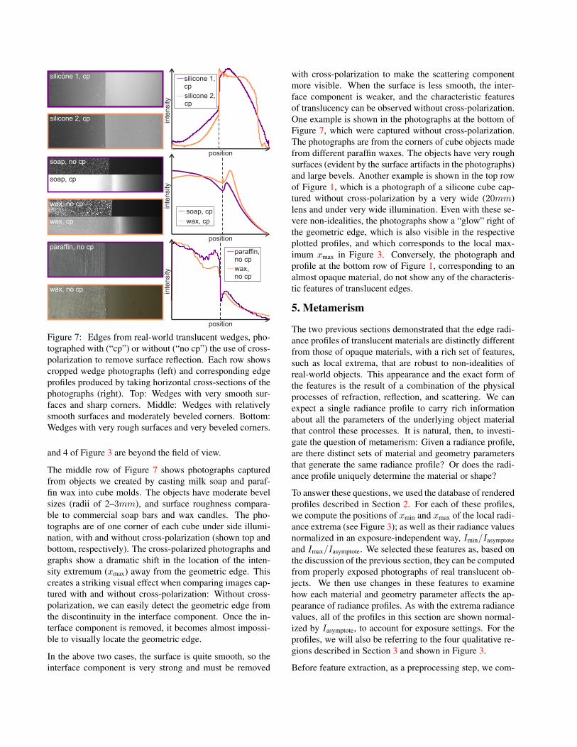
flection boundary, the radiance profile has an exponentialrise immediately left of the edge. It is possible, however,to select an illumination direction such that left view raysnever intersect with the reflection boundary, as shown in theleft column of Figure 6. In this case, left view rays neverenter the high-flux area of the zero-scattering lightfield, andthe single-scattering radiance profile is constant everywhereleft of the edge.
Mid-order scattering has the effect of blurring the discon-tinuity at the internal reflection boundary, as radiance getsscattered from the high-flux towards the low-flux area ofthe lightfield. This is shown at the bottom row of Figure 6,which plots 1D cross-sections through the single and mid-order scattering flux fields. The sharp discontinuity at thereflection boundary p seen in the single-scattering field isblurred into a smooth transition in the mid-order field. Dueto this blurring, left view rays near the boundary can pick upsome radiance from the high-flux area even if they do not in-tersect the boundary. Therefore, there can be an exponentialrise region left of the edge in the mid-order-scattering radi-ance profile (and in the full radiance profile), even when itis not present in the single-scattering radiance profile (leftcolumn of Figure 6).
4. Effects of Non-Idealities
The analysis of the previous section is based on an idealwedge model. Though convenient for analysis, such exactgeometry is unlikely to be encountered in real-world scenes.It is therefore worth understanding how the characteristicfeatures of translucent profiles are affected by deviationsfrom this model.
There are typically three non-idealities that one will en-counter in a realization of the wedge geometry: First, it isimpossible to have perfectly collimated light and an exactlyorthographic camera. Second, the surfaces of a real wedgewill not be perfectly smooth, but have microstructure result-ing in a BRDF that is not perfectly specular. Third, a realwedge will not have an exact corner, but instead will have abevel of some non-zero radius. In the supplementary mate-rial, we use Monte Carlo simulations to examine the effectof each of these non-idealities on edge radiance profiles.The simulations show that non-zero solid angles for the il-lumination and camera have negligible effect on the shapeof the radiance profile. Additionally, radiance profiles main-tain all of their characteristic features for a reasonable rangeof surface roughness values, though unsurprisingly not forvery rough interfaces such as etched surfaces. The largesteffect comes from having a bevelled, or rounded, wedgeapex. It effectively “erases” the profile features whose dis-tance from the apex is less than the radius of the bevel. Theexponential rise in region 2 of Figure 3 is particularly sus-ceptible, and it disappears even for small bevels. In contrast,
inte
nsity
inte
nsity
position position
single scatteringmid-order scattering
p q pq
v v
l1 l2
r1 r2
v
v
single scattering
0
1
flux
0.5
pqp q
vv
l1 l2
r1 r2
mid-order scattering
0
1
flux
0.5
qp q p
single scattering
mid-order scattering
v vr1 r2
flux
flux
v
v
Figure 6: Comparison of single and mid-order scatteringfor two configurations (left and right column) differing onlyin illumination direction. The top row shows the radianceprofiles for single and mid-order scattering in each case.The middle rows show the corresponding flux fields. Thechange in illumination direction from l1 (left) to l2 (right)also changes the internal reflection boundary (dashed line).A view ray v entering the wedge left of the geometric edgewill not intersect the reflection boundary in the case of l1,but will intersect it in the case of l2. The bottom graphsshow the flux values along the 1D cross-section segment in-dicated inside the volume. Point p is intersection of the seg-ment with view ray v; point q is intersection of the segmentwith the internal reflection boundary.
our simulations show that the local extrema at xmin and xmaxare quite robust to all non-idealities, including beveling.
In addition to simulations, we captured photographs oftranslucent wedges under increasingly non-ideal conditions.The top row of Figure 7 shows photographs of wedges wecreated by mixing clear silicone with different optical scat-terers and casting the mixtures into optically smooth molds.These objects have very smooth surfaces and very sharp ge-ometric edges. We photographed these objects using cross-polarization to approximately remove the strong, near spec-ular, interface component [23, 7]. Under these near-idealconditions, the photographs exhibit all of the characteristicfeatures, including the local minimum and sharp rise left ofthe geometric edge, and the local maximum right of it. Wenote that, due to the simultaneously small physical size ofthe molds and small density of the two materials, regions 1
position
paraffin, no cp
wax, no cp
inte
nsi
ty
position
inte
nsi
ty
soap, cp
wax, cp
position
inte
nsity
silicone 1, cp
silicone 2, cp
silicone 1, cp
silicone 2, cp
soap, no cp
paraffin, no cp
wax, no cp
soap, cp
wax, no cp
wax, cp
Figure 7: Edges from real-world translucent wedges, pho-tographed with (“cp”) or without (“no cp”) the use of cross-polarization to remove surface reflection. Each row showscropped wedge photographs (left) and corresponding edgeprofiles produced by taking horizontal cross-sections of thephotographs (right). Top: Wedges with very smooth sur-faces and sharp corners. Middle: Wedges with relativelysmooth surfaces and moderately beveled corners. Bottom:Wedges with very rough surfaces and very beveled corners.
and 4 of Figure 3 are beyond the field of view.
The middle row of Figure 7 shows photographs capturedfrom objects we created by casting milk soap and paraf-fin wax into cube molds. The objects have moderate bevelsizes (radii of 2–3mm), and surface roughness compara-ble to commercial soap bars and wax candles. The pho-tographs are of one corner of each cube under side illumi-nation, with and without cross-polarization (shown top andbottom, respectively). The cross-polarized photographs andgraphs show a dramatic shift in the location of the inten-sity extremum (xmax) away from the geometric edge. Thiscreates a striking visual effect when comparing images cap-tured with and without cross-polarization: Without cross-polarization, we can easily detect the geometric edge fromthe discontinuity in the interface component. Once the in-terface component is removed, it becomes almost impossi-ble to visually locate the geometric edge.
In the above two cases, the surface is quite smooth, so theinterface component is very strong and must be removed
with cross-polarization to make the scattering componentmore visible. When the surface is less smooth, the inter-face component is weaker, and the characteristic featuresof translucency can be observed without cross-polarization.One example is shown in the photographs at the bottom ofFigure 7, which were captured without cross-polarization.The photographs are from the corners of cube objects madefrom different paraffin waxes. The objects have very roughsurfaces (evident by the surface artifacts in the photographs)and large bevels. Another example is shown in the top rowof Figure 1, which is a photograph of a silicone cube cap-tured without cross-polarization by a very wide (20mm)lens and under very wide illumination. Even with these se-vere non-idealities, the photographs show a “glow” right ofthe geometric edge, which is also visible in the respectiveplotted profiles, and which corresponds to the local max-imum xmax in Figure 3. Conversely, the photograph andprofile at the bottom row of Figure 1, corresponding to analmost opaque material, do not show any of the characteris-tic features of translucent edges.
5. Metamerism
The two previous sections demonstrated that the edge radi-ance profiles of translucent materials are distinctly differentfrom those of opaque materials, with a rich set of features,such as local extrema, that are robust to non-idealities ofreal-world objects. This appearance and the exact form ofthe features is the result of a combination of the physicalprocesses of refraction, reflection, and scattering. We canexpect a single radiance profile to carry rich informationabout all the parameters of the underlying object materialthat control these processes. It is natural, then, to investi-gate the question of metamerism: Given a radiance profile,are there distinct sets of material and geometry parametersthat generate the same radiance profile? Or does the radi-ance profile uniquely determine the material or shape?
To answer these questions, we used the database of renderedprofiles described in Section 2. For each of these profiles,we compute the positions of xmin and xmax of the local radi-ance extrema (see Figure 3); as well as their radiance valuesnormalized in an exposure-independent way, Imin/Iasymptoteand Imax/Iasymptote. We selected these features as, based onthe discussion of the previous section, they can be computedfrom properly exposed photographs of real translucent ob-jects. We then use changes in these features to examinehow each material and geometry parameter affects the ap-pearance of radiance profiles. As with the extrema radiancevalues, all of the profiles in this section are shown normal-ized by Iasymptote, to account for exposure settings. For theprofiles, we will also be referring to the four qualitative re-gions described in Section 3 and shown in Figure 3.
Before feature extraction, as a preprocessing step, we com-
inte
nsity
position
albedofirst moment
second moment
second moment
first moment
albedo
density
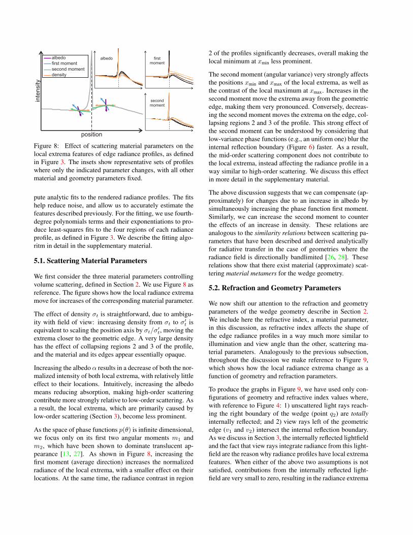
Figure 8: Effect of scattering material parameters on thelocal extrema features of edge radiance profiles, as definedin Figure 3. The insets show representative sets of profileswhere only the indicated parameter changes, with all othermaterial and geometry parameters fixed.
pute analytic fits to the rendered radiance profiles. The fitshelp reduce noise, and allow us to accurately estimate thefeatures described previously. For the fitting, we use fourth-degree polynomials terms and their exponentiations to pro-duce least-squares fits to the four regions of each radianceprofile, as defined in Figure 3. We describe the fitting algo-ritm in detail in the supplementary material.
5.1. Scattering Material Parameters
We first consider the three material parameters controllingvolume scattering, defined in Section 2. We use Figure 8 asreference. The figure shows how the local radiance extremamove for increases of the corresponding material parameter.
The effect of density σt is straightforward, due to ambigu-ity with field of view: increasing density from σt to σ′t isequivalent to scaling the position axis by σt/σ′t, moving theextrema closer to the geometric edge. A very large densityhas the effect of collapsing regions 2 and 3 of the profile,and the material and its edges appear essentially opaque.
Increasing the albedo α results in a decrease of both the nor-malized intensity of both local extrema, with relatively littleeffect to their locations. Intuitively, increasing the albedomeans reducing absorption, making high-order scatteringcontribute more strongly relative to low-order scattering. Asa result, the local extrema, which are primarily caused bylow-order scattering (Section 3), become less prominent.
As the space of phase functions p(θ) is infinite dimensional,we focus only on its first two angular moments m1 andm2, which have been shown to dominate translucent ap-pearance [13, 27]. As shown in Figure 8, increasing thefirst moment (average direction) increases the normalizedradiance of the local extrema, with a smaller effect on theirlocations. At the same time, the radiance contrast in region
2 of the profiles significantly decreases, overall making thelocal minimum at xmin less prominent.
The second moment (angular variance) very strongly affectsthe positions xmin and xmax of the local extrema, as well asthe contrast of the local maximum at xmax. Increases in thesecond moment move the extrema away from the geometricedge, making them very pronounced. Conversely, decreas-ing the second moment moves the extrema on the edge, col-lapsing regions 2 and 3 of the profile. This strong effect ofthe second moment can be understood by considering thatlow-variance phase functions (e.g., an uniform one) blur theinternal reflection boundary (Figure 6) faster. As a result,the mid-order scattering component does not contribute tothe local extrema, instead affecting the radiance profile in away similar to high-order scattering. We discuss this effectin more detail in the supplementary material.
The above discussion suggests that we can compensate (ap-proximately) for changes due to an increase in albedo bysimultaneously increasing the phase function first moment.Similarly, we can increase the second moment to counterthe effects of an increase in density. These relations areanalogous to the similarity relations between scattering pa-rameters that have been described and derived analyticallyfor radiative transfer in the case of geometries where theradiance field is directionally bandlimited [26, 28]. Theserelations show that there exist material (approximate) scat-tering material metamers for the wedge geometry.
5.2. Refraction and Geometry Parameters
We now shift our attention to the refraction and geometryparameters of the wedge geometry describe in Section 2.We include here the refractive index, a material parameter,in this discussion, as refractive index affects the shape ofthe edge radiance profiles in a way much more similar toillumination and view angle than the other, scattering ma-terial parameters. Analogously to the previous subsection,throughout the discussion we make reference to Figure 9,which shows how the local radiance extrema change as afunction of geometry and refraction parameters.
To produce the graphs in Figure 9, we have used only con-figurations of geometry and refractive index values where,with reference to Figure 4: 1) unscattered light rays reach-ing the right boundary of the wedge (point q2) are totallyinternally reflected; and 2) view rays left of the geometricedge (v1 and v2) intersect the internal reflection boundary.As we discuss in Section 3, the internally reflected lightfieldand the fact that view rays integrate radiance from this light-field are the reason why radiance profiles have local extremafeatures. When either of the above two assumptions is notsatisfied, contributions from the internally reflected light-field are very small to zero, resulting in the radiance extrema
inte
nsi
ty
position
refractive indexview angleillumination angle
illumination angle
viewangle
refractive index
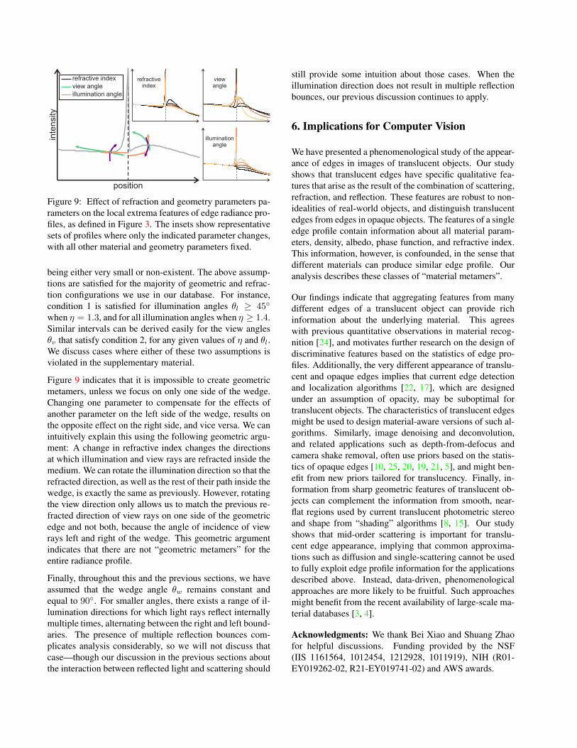
Figure 9: Effect of refraction and geometry parameters pa-rameters on the local extrema features of edge radiance pro-files, as defined in Figure 3. The insets show representativesets of profiles where only the indicated parameter changes,with all other material and geometry parameters fixed.
being either very small or non-existent. The above assump-tions are satisfied for the majority of geometric and refrac-tion configurations we use in our database. For instance,condition 1 is satisfied for illumination angles θl ≥ 45◦
when η = 1.3, and for all illumination angles when η ≥ 1.4.Similar intervals can be derived easily for the view anglesθv that satisfy condition 2, for any given values of η and θl.We discuss cases where either of these two assumptions isviolated in the supplementary material.
Figure 9 indicates that it is impossible to create geometricmetamers, unless we focus on only one side of the wedge.Changing one parameter to compensate for the effects ofanother parameter on the left side of the wedge, results onthe opposite effect on the right side, and vice versa. We canintuitively explain this using the following geometric argu-ment: A change in refractive index changes the directionsat which illumination and view rays are refracted inside themedium. We can rotate the illumination direction so that therefracted direction, as well as the rest of their path inside thewedge, is exactly the same as previously. However, rotatingthe view direction only allows us to match the previous re-fracted direction of view rays on one side of the geometricedge and not both, because the angle of incidence of viewrays left and right of the wedge. This geometric argumentindicates that there are not “geometric metamers” for theentire radiance profile.
Finally, throughout this and the previous sections, we haveassumed that the wedge angle θw remains constant andequal to 90◦. For smaller angles, there exists a range of il-lumination directions for which light rays reflect internallymultiple times, alternating between the right and left bound-aries. The presence of multiple reflection bounces com-plicates analysis considerably, so we will not discuss thatcase—though our discussion in the previous sections aboutthe interaction between reflected light and scattering should
still provide some intuition about those cases. When theillumination direction does not result in multiple reflectionbounces, our previous discussion continues to apply.
6. Implications for Computer Vision
We have presented a phenomenological study of the appear-ance of edges in images of translucent objects. Our studyshows that translucent edges have specific qualitative fea-tures that arise as the result of the combination of scattering,refraction, and reflection. These features are robust to non-idealities of real-world objects, and distinguish translucentedges from edges in opaque objects. The features of a singleedge profile contain information about all material param-eters, density, albedo, phase function, and refractive index.This information, however, is confounded, in the sense thatdifferent materials can produce similar edge profile. Ouranalysis describes these classes of “material metamers”.
Our findings indicate that aggregating features from manydifferent edges of a translucent object can provide richinformation about the underlying material. This agreeswith previous quantitative observations in material recog-nition [24], and motivates further research on the design ofdiscriminative features based on the statistics of edge pro-files. Additionally, the very different appearance of translu-cent and opaque edges implies that current edge detectionand localization algorithms [22, 17], which are designedunder an assumption of opacity, may be suboptimal fortranslucent objects. The characteristics of translucent edgesmight be used to design material-aware versions of such al-gorithms. Similarly, image denoising and deconvolution,and related applications such as depth-from-defocus andcamera shake removal, often use priors based on the statis-tics of opaque edges [10, 25, 20, 19, 21, 5], and might ben-efit from new priors tailored for translucency. Finally, in-formation from sharp geometric features of translucent ob-jects can complement the information from smooth, near-flat regions used by current translucent photometric stereoand shape from “shading” algorithms [8, 15]. Our studyshows that mid-order scattering is important for translu-cent edge appearance, implying that common approxima-tions such as diffusion and single-scattering cannot be usedto fully exploit edge profile information for the applicationsdescribed above. Instead, data-driven, phenomenologicalapproaches are more likely to be fruitful. Such approachesmight benefit from the recent availability of large-scale ma-terial databases [3, 4].
Acknowledgments: We thank Bei Xiao and Shuang Zhaofor helpful discussions. Funding provided by the NSF(IIS 1161564, 1012454, 1212928, 1011919), NIH (R01-EY019262-02, R21-EY019741-02) and AWS awards.
References
[1] Project page. http://vision.seas.harvard.edu/translucentedges/. 3
[2] E. Adelson. On seeing stuff: the perception of materi-als by humans and machines. Proceedings of the SPIEVol. 4299, Human Vision and Electronic Imaging VI,2001. 1
[3] S. Bell, P. Upchurch, N. Snavely, and K. Bala. Open-surfaces: A richly annotated catalog of surface appear-ance. ACM Transactions on Graphics, 2013. 8
[4] S. Bell, P. Upchurch, N. Snavely, and K. Bala. Mate-rial recognition in the wild with the materials in con-text database. IEEE CVPR, 2015. 8
[5] A. Chakrabarti and T. Zickler. Depth and deblurringfrom a spectrally-varying depth-of-field. ECCV, 2012.8
[6] S. Chandrasekhar. Radiative transfer. Dover, 1960. 2
[7] T. Chen, H. Lensch, C. Fuchs, and H.-P. Seidel. Polar-ization and phase-shifting for 3d scanning of translu-cent objects. IEEE CVPR, 2007. 5
[8] B. Dong, K. D. Moore, W. Zhang, and P. Peers. Scat-tering parameters and surface normals from homoge-neous translucent materials using photometric stereo.IEEE CVPR, 2014. 8
[9] C. Donner and H. Jensen. Rendering translucent ma-terials using photon diffusion. ACM SIGGRAPH 2008Classes, 2008. 4
[10] R. Fergus, B. Singh, A. Hertzmann, S. T. Roweis, andW. T. Freeman. Removing camera shake from a singlephotograph. ACM Transactions on Graphics, 2006. 8
[11] R. Fleming and H. Bulthoff. Low-level image cues inthe perception of translucent materials. ACM Trans-actions on Applied Perception, 2005. 1
[12] J. R. Frisvad, N. J. Christensen, and H. W. Jensen.Computing the scattering properties of participatingmedia using lorenz-mie theory. 2007. 3
[13] I. Gkioulekas, B. Xiao, S. Zhao, E. Adelson, T. Zick-ler, and K. Bala. Understanding the role of phase func-tion in translucent appearance. ACM Transactions onGraphics, 2013. 1, 3, 7
[14] I. Gkioulekas, S. Zhao, K. Bala, T. Zickler, andA. Levin. Inverse volume rendering with material dic-tionaries. ACM Transactions on Graphics, 2013. 3
[15] C. Inoshita, Y. Mukaigawa, Y. Matsushita, andY. Yagi. Surface normal deconvolution: Photometric
stereo for optically thick translucent objects. ECCV,2014. 8
[16] A. Ishimaru. Wave propagation and scattering in ran-dom media. Wiley-IEEE, 1978. 2, 4
[17] P. Isola, D. Zoran, D. Krishnan, and E. H. Adelson.Crisp boundary detection using pointwise mutual in-formation. ECCV, 2014. 8
[18] H. Jensen, S. Marschner, M. Levoy, and P. Hanrahan.A practical model for subsurface light transport. InSIGGRAPH, 2001. 4
[19] N. Joshi, R. Szeliski, and D. Kriegman. Psf estimationusing sharp edge prediction. IEEE CVPR, 2008. 8
[20] A. Levin, R. Fergus, F. Durand, and W. T. Freeman.Image and depth from a conventional camera with acoded aperture. ACM Transactions on Graphics, 2007.8
[21] A. Levin, Y. Weiss, F. Durand, and W. Freeman. Un-derstanding and evaluating blind deconvolution algo-rithms. IEEE CVPR, 2009. 8
[22] D. R. Martin, C. C. Fowlkes, and J. Malik. Learningto detect natural image boundaries using local bright-ness, color, and texture cues. IEEE PAMI, 2004. 8
[23] S. H. Mersch. Polarized lighting for machine visionapplications. Society of Manufacturing Engineers,1984. 5
[24] L. Sharan, C. Liu, R. Rosenholtz, and E. Adel-son. Recognizing materials using perceptually in-spired features. International Journal of Computer Vi-sion, 2013. 8
[25] Y. Weiss and W. T. Freeman. What makes a goodmodel of natural images? CVPR, 2007. 8
[26] D. Wyman, M. Patterson, and B. Wilson. Similar-ity relations for the interaction parameters in radiationtransport. Applied optics, 1989. 7
[27] B. Xiao, B. Walter, I. Gkioulekas, T. Zickler, E. Adel-son, and K. Bala. Looking against the light: how per-ception of translucency depends on lighting directionand phase function. Journal of Vision, 2014. 1, 7
[28] S. Zhao, R. Ramamoorthi, and K. Bala. Higher-ordersimilarity relations in radiative transfer. ACM Trans-actions on Graphics, 2014. 7