Embed Size (px)
Citation preview
Mech. Sci., 11, 29–38, 2020https://doi.org/10.5194/ms-11-29-2020© Author(s) 2020. This work is distributed underthe Creative Commons Attribution 4.0 License.
On the analysis and design of a fully compliantlarge stroke slider-crank (rocker) mechanism
Çagıl Merve Tanık1, Engin Tanık2, Yigit Yazıcıoglu1, and Volkan Parlaktas2
1Department of Mechanical Engineering, Middle East Technical University, 06800 Ankara, Turkey2Department of Mechanical Engineering, Hacettepe University, 06800 Ankara, Turkey
Correspondence: Engin Tanık ([email protected])
Received: 27 May 2019 – Revised: 1 January 2020 – Accepted: 20 January 2020 – Published: 7 February 2020
Abstract. In the literature, authors have made contributions in the area of partially compliant slider-crank(rocker) mechanisms possessing rigid joints that may cause backlash inherently. On contrary, fully compliantmechanisms offer no backlash which is a valuable property for the cases where high precision is required. In thispaper, we proposed a fully compliant slider-crank mechanism that performs large stroke. Kinematic performanceof the mechanism is investigated analytically. Dimensions of the mechanism are optimized to obtain maximumtranslational output, while keeping deflections of flexible hinges equal to each other and as small as possible.A design table displaying stroke, axis drift of the output segment, and critical stresses of compliant segmentsare presented. As an example, a compliant mechanism is designed by using rigid body replacement technique.Then, via nonlinear finite element analysis technique, analytical results are verified. Finally, a prototype is builtto compare output stroke and axis drift with analytical approaches. The results of experiments verified that thetheoretical approaches are consistent.
1 Introduction
Compliant mechanisms are flexible mechanisms that trans-fer some or all of their motion through deformation of elas-tic segments. They are divided into two main categories;partially or fully compliant mechanism. Partially compliantmechanisms have at least one traditional (rigid) joint thatmay cause backlash inherently. By definition, a fully compli-ant mechanism does not possess a conventional rigid joint.Thus, fully compliant mechanisms obtain all their motionfrom deflection of compliant segments (Howell, 2001). Thisproperty is advantageous for the cases where precision is cru-cial. Compliant mechanisms have further advantages such aslow cost, reduced number of parts, no need for lubrication,less wear and noise. Additionally, stored elastic energy due todeformation of compliant members brings mechanism to itsoriginal position. Pseudo-rigid-body model (PRBM) is usedto simplify analysis of systems that undergo large, nonlineardeflections (Howell and Midha, 1996). Yu et al. (2016) pro-posed a new three degree-of-freedom (DOF) model based onPRBM for large deflection beams. In Liu and Yan’s (2017)
study modified pseudo-rigid- body modelling approach forcompliant mechanisms with fixed guided beam flexurals wasexamined.
Rigid joints allow specific DOF between connected parts.However, rigid joints suffer from backlash and wear becauseof clearance between mating parts. Trease et al. (2005) pro-posed a revolute and translational compliant joint. Anothernovel three dimensional compliant translational joint withlarge stiffness ratio and small axis drift was presented (Yanget al., 2016).
Four link mechanisms (e.g. four-bar and slider-crank) havesignificant importance in the industry. Slider-crank mech-anisms have numerous applications especially when kine-matic inversions are considered. Researches on compliantslider-crank (rocker) mechanisms are limited in the litera-ture. Hao et al. (2018) proposed a multi-mode compliantgripper. There is a fully compliant slider-crank mechanismavailable in their gripper. In Parlaktas and Tanık’s (2014)study the “single piece” compliant spatial slider-crank mech-anism was introduced. In this study, deflections of the multi-ple axis flexural hinges were determined separately as bend-
Published by Copernicus Publications.
30 Ç. M. Tanık et al.: On the analysis and design of a fully compliant large stroke slider-crank (rocker) mechanism
ing and twist. Erkaya et al. (2016) investigated dynam-ics of the partially compliant slider-crank mechanism. InAlqasimi et al.’s (2016) study, a new model for a bistablecompliant mechanism that is based on crank-slider mecha-nism was presented. In this study the slider is rigid thus themechanism is partially compliant. In Pardeshi et al.’s (2017)study, monolithic compliant slider-crank mechanism with arigid slider for motion amplification was proposed. Dao andHuang (2014) proposed an optimal design of a partially com-pliant slider-crank mechanism with circular cross-sectionflexure hinges.
Furthermore, there are some studies based on compliantlinear-motion mechanisms which can not be categorized asslider-crank mechanism: Pavlovic and Pavlovic (2009) intro-duced compliant parallel-guiding mechanism’s design proce-dure. A new compliant mechanism which is capable to real-ize axial translation of the link was presented. An inherentparasitic motion of the compliant parallel four-bar mecha-nism was compensated by exploiting center shift of a gen-eralized cross-spring pivot in Hongzhe et al.’s (2012) study.Zhao, et al. (2017) designed a stiffness-adjustable compliantlinear-motion mechanism.
Partially compliant mechanisms possess rigid prismaticjoints (slider) in their structure. Prismatic joints inherentlyhave disadvantages due to backlash and friction problems.An approach for optimum link proportions of the rigid bodyequivalent is proposed. The optimization objective is to max-imize the translational motion of the slider equivalent whileminimizing the relative link rotations. Minimization of linkrotations is essential to keep maximum stresses in an accept-able range. Input–output motion relationships of the mecha-nism are determined. Resultant stresses at flexural hinges areobtained analytically. A design table is prepared for gener-alization of the dimensions that will be beneficial for otherresearchers. As a design example, an optimum mechanismis analyzed via finite element analysis (FEA) method andanalytical results are verified. A prototype is manufacturedand experiments are conducted. Also, it is ensured that theresults of experiments are consistent with the theoretical ap-proaches.
Note that, for the cases where crank of a slider-crankmechanism does not fully rotate, the mechanism may becalled as slider-rocker mechanism. However, this makes anambiguity for the identity of the mechanism. In this study,we prefer to name the mechanism as slider-crank disregard-ing the link proportions.
2 The proposed fully compliant slider-crankmechanism
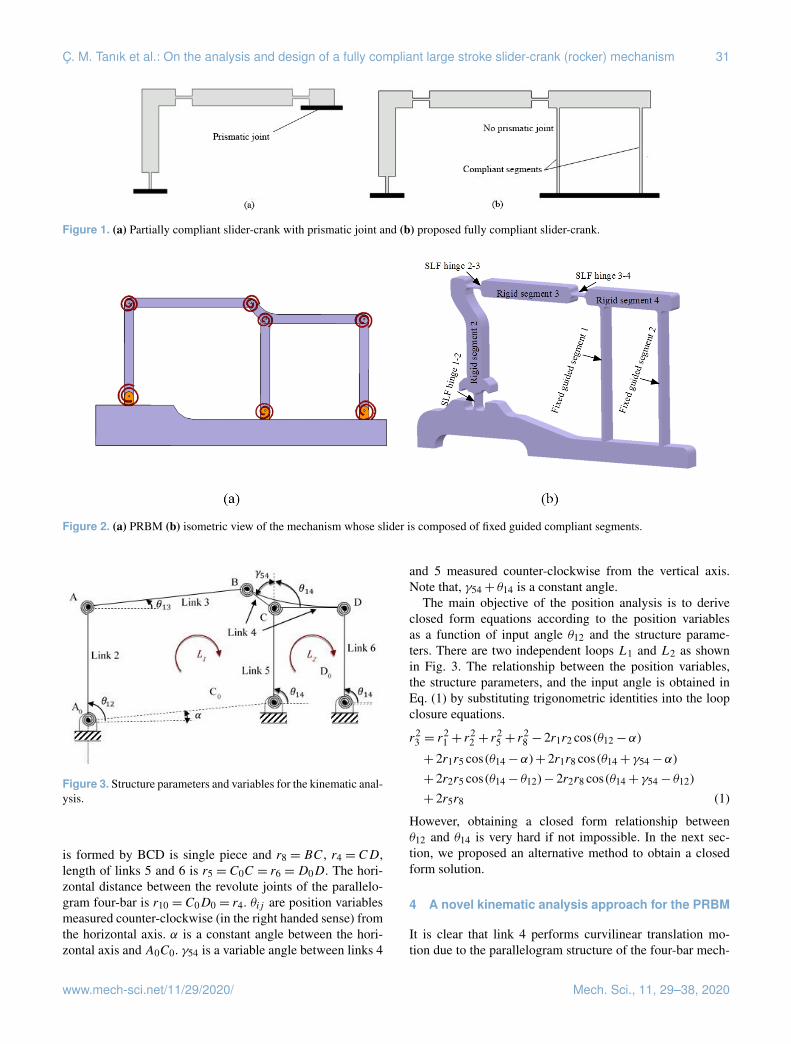
In Fig. 1a, a partially compliant slider-crank mechanism thatpossesses a prismatic joint between the slider and groundis presented. In our design, we replaced the prismatic jointby two identical and parallel compliant segments and a rigid
segment as shown in Fig. 1b. By this way, if properly de-signed, translational motion for the output which acts asa slider can be achieved. Alternatively, compliant versionof Roberts or Watt (Shigley and Uicker, 1980) type fourbar mechanisms can be implemented for slider replacement.Specific points on coupler link of these mechanisms traceapproximate straight lines. However, their coupler link per-forms rotation as well as translation. In our case, the out-put link performs no rotation but only translation (curvilin-ear translation). In the literature, paired double parallelogrammechanisms are used as sliders (Trease et al., 2005; Li et al.,2018). The advantage of this structure is straight line motionwith no rotation. However, there is a big major disadvantage;if PRBM of this type is constructed, it can be calculated thatDOF < 0. This case yields a locking mechanism. However,compliant version of this mechanism moves with axial de-formation of compliant segments as well as bending. Thisproperty increases the stresses, therefore decreases stroke ofthe mechanism dramatically. Our major concern in this studyis to increase the stroke as high as possible while keeping thestresses in an acceptable range.
In Fig. 2a, PRBM of the fully compliant slider-crankmechanism is displayed. This PRBM is essentially a six-linkmechanism, where two of the links are connected to a paral-lelogram four-bar mechanism. The coupler link of this par-allelogram four-bar acts as a slider, if the fixed guided seg-ments 1 and 2 are long enough and rigid segment 4 staysparallel to its initial position (Fig. 2b). These fixed guidedsegments must be identical, initially straight, and parallelto each other. By this way, we obtain a compliant parallel-guiding mechanism (Howell, 2001) where rigid segment 4performs curvilinear translation. In the case of an extremevertical load, fixed guided segments may buckle thus, rigidsegment 4 becomes nonparallel to its initial position.
3 Kinematic analysis of the cascade parallelogramfour-bar mechanism
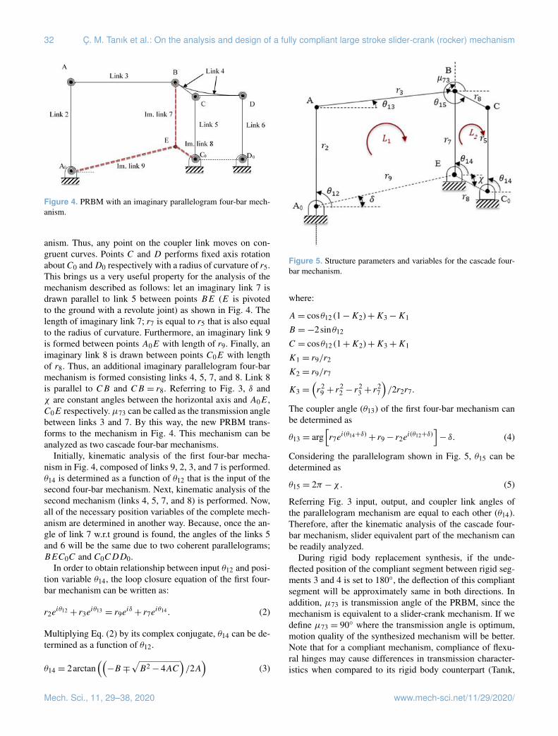
Initially, kinematic analysis of the PRBM which is essen-tially a rigid cascade parallelogram four-bar mechanisms isperformed. The PRBM (Fig. 3) is formed as follows: input(link 2) and connecting rod (link 3) of the mechanism arecombined with a parallelogram four-bar mechanism whosecoupler link (link 4) acts as a slider of the fully compliantslider-crank mechanism (Fig. 2b).
Kutzbach criterion (Shigley and Uicker, 1980) for DOF ofa planar mechanism isN = 3(l−1)−2j1−j2 where j1 refersto the number of single DOF joints and j2 refers to the num-ber of two DOF joints. The PRBM has six links and sevenrevolute joints. Thus, according to Kutzbach criterion, DOFof the mechanism is calculated as N = 1.
Referring to Fig. 3, the revolute joints at A0, C0, andD0 are pivoted to the ground. Length of r1 is A0C0, length oflink 2 is r2 = A0A, length of link 3 is r3 = AB. Link 4 that
Mech. Sci., 11, 29–38, 2020 www.mech-sci.net/11/29/2020/
Ç. M. Tanık et al.: On the analysis and design of a fully compliant large stroke slider-crank (rocker) mechanism 31
Figure 1. (a) Partially compliant slider-crank with prismatic joint and (b) proposed fully compliant slider-crank.
Figure 2. (a) PRBM (b) isometric view of the mechanism whose slider is composed of fixed guided compliant segments.
Figure 3. Structure parameters and variables for the kinematic anal-ysis.
is formed by BCD is single piece and r8 = BC, r4 = CD,length of links 5 and 6 is r5 = C0C = r6 =D0D. The hori-zontal distance between the revolute joints of the parallelo-gram four-bar is r10 = C0D0 = r4. θij are position variablesmeasured counter-clockwise (in the right handed sense) fromthe horizontal axis. α is a constant angle between the hori-zontal axis and A0C0. γ54 is a variable angle between links 4
and 5 measured counter-clockwise from the vertical axis.Note that, γ54+ θ14 is a constant angle.
The main objective of the position analysis is to deriveclosed form equations according to the position variablesas a function of input angle θ12 and the structure parame-ters. There are two independent loops L1 and L2 as shownin Fig. 3. The relationship between the position variables,the structure parameters, and the input angle is obtained inEq. (1) by substituting trigonometric identities into the loopclosure equations.
r23 = r
21 + r
22 + r
25 + r
28 − 2r1r2 cos(θ12−α)
+ 2r1r5 cos(θ14−α)+ 2r1r8 cos(θ14+ γ54−α)+ 2r2r5 cos(θ14− θ12)− 2r2r8 cos(θ14+ γ54− θ12)+ 2r5r8 (1)
However, obtaining a closed form relationship betweenθ12 and θ14 is very hard if not impossible. In the next sec-tion, we proposed an alternative method to obtain a closedform solution.
4 A novel kinematic analysis approach for the PRBM
It is clear that link 4 performs curvilinear translation mo-tion due to the parallelogram structure of the four-bar mech-
www.mech-sci.net/11/29/2020/ Mech. Sci., 11, 29–38, 2020
32 Ç. M. Tanık et al.: On the analysis and design of a fully compliant large stroke slider-crank (rocker) mechanism
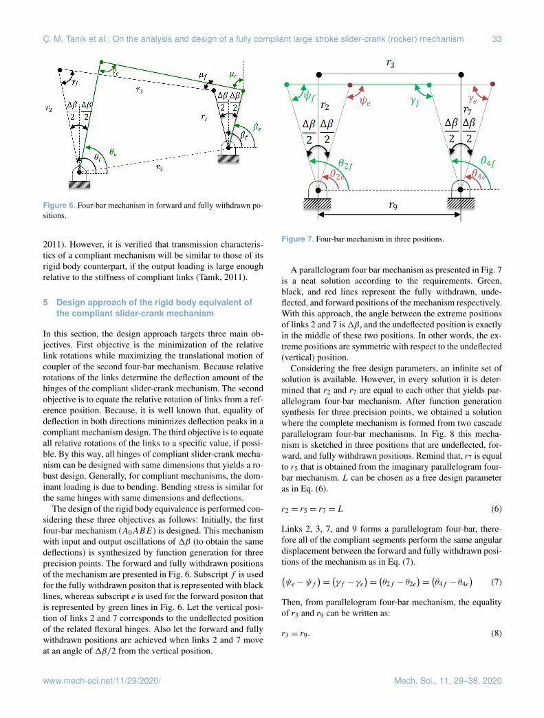
Figure 4. PRBM with an imaginary parallelogram four-bar mech-anism.
anism. Thus, any point on the coupler link moves on con-gruent curves. Points C and D performs fixed axis rotationaboutC0 andD0 respectively with a radius of curvature of r5.This brings us a very useful property for the analysis of themechanism described as follows: let an imaginary link 7 isdrawn parallel to link 5 between points BE (E is pivotedto the ground with a revolute joint) as shown in Fig. 4. Thelength of imaginary link 7; r7 is equal to r5 that is also equalto the radius of curvature. Furthermore, an imaginary link 9is formed between points A0E with length of r9. Finally, animaginary link 8 is drawn between points C0E with lengthof r8. Thus, an additional imaginary parallelogram four-barmechanism is formed consisting links 4, 5, 7, and 8. Link 8is parallel to CB and CB = r8. Referring to Fig. 3, δ andχ are constant angles between the horizontal axis and A0E,C0E respectively.µ73 can be called as the transmission anglebetween links 3 and 7. By this way, the new PRBM trans-forms to the mechanism in Fig. 4. This mechanism can beanalyzed as two cascade four-bar mechanisms.
Initially, kinematic analysis of the first four-bar mecha-nism in Fig. 4, composed of links 9, 2, 3, and 7 is performed.θ14 is determined as a function of θ12 that is the input of thesecond four-bar mechanism. Next, kinematic analysis of thesecond mechanism (links 4, 5, 7, and 8) is performed. Now,all of the necessary position variables of the complete mech-anism are determined in another way. Because, once the an-gle of link 7 w.r.t ground is found, the angles of the links 5and 6 will be the same due to two coherent parallelograms;BEC0C and C0CDD0.
In order to obtain relationship between input θ12 and posi-tion variable θ14, the loop closure equation of the first four-bar mechanism can be written as:
r2eiθ12 + r3e
iθ13 = r9eiδ+ r7e
iθ14 . (2)
Multiplying Eq. (2) by its complex conjugate, θ14 can be de-termined as a function of θ12.
θ14 = 2arctan((−B ∓
√B2− 4AC
)/2A
)(3)
Figure 5. Structure parameters and variables for the cascade four-bar mechanism.
where:
A= cosθ12 (1−K2)+K3−K1
B =−2sinθ12
C = cosθ12 (1+K2)+K3+K1
K1 = r9/r2
K2 = r9/r7
K3 =(r2
9 + r22 − r
23 + r
27
)/2r2r7.
The coupler angle (θ13) of the first four-bar mechanism canbe determined as
θ13 = arg[r7e
i(θ14+δ)+ r9− r2ei(θ12+δ)
]− δ. (4)
Considering the parallelogram shown in Fig. 5, θ15 can bedetermined as
θ15 = 2π −χ. (5)
Referring Fig. 3 input, output, and coupler link angles ofthe parallelogram mechanism are equal to each other (θ14).Therefore, after the kinematic analysis of the cascade four-bar mechanism, slider equivalent part of the mechanism canbe readily analyzed.
During rigid body replacement synthesis, if the unde-flected position of the compliant segment between rigid seg-ments 3 and 4 is set to 180◦, the deflection of this compliantsegment will be approximately same in both directions. Inaddition, µ73 is transmission angle of the PRBM, since themechanism is equivalent to a slider-crank mechanism. If wedefine µ73 = 90◦ where the transmission angle is optimum,motion quality of the synthesized mechanism will be better.Note that for a compliant mechanism, compliance of flexu-ral hinges may cause differences in transmission character-istics when compared to its rigid body counterpart (Tanık,
Mech. Sci., 11, 29–38, 2020 www.mech-sci.net/11/29/2020/
Ç. M. Tanık et al.: On the analysis and design of a fully compliant large stroke slider-crank (rocker) mechanism 33
Figure 6. Four-bar mechanism in forward and fully withdrawn po-sitions.
2011). However, it is verified that transmission characteris-tics of a compliant mechanism will be similar to those of itsrigid body counterpart, if the output loading is large enoughrelative to the stiffness of compliant links (Tanık, 2011).
5 Design approach of the rigid body equivalent ofthe compliant slider-crank mechanism
In this section, the design approach targets three main ob-jectives. First objective is the minimization of the relativelink rotations while maximizing the translational motion ofcoupler of the second four-bar mechanism. Because relativerotations of the links determine the deflection amount of thehinges of the compliant slider-crank mechanism. The secondobjective is to equate the relative rotation of links from a ref-erence position. Because, it is well known that, equality ofdeflection in both directions minimizes deflection peaks in acompliant mechanism design. The third objective is to equateall relative rotations of the links to a specific value, if possi-ble. By this way, all hinges of compliant slider-crank mecha-nism can be designed with same dimensions that yields a ro-bust design. Generally, for compliant mechanisms, the dom-inant loading is due to bending. Bending stress is similar forthe same hinges with same dimensions and deflections.
The design of the rigid body equivalence is performed con-sidering these three objectives as follows: Initially, the firstfour-bar mechanism (A0ABE) is designed. This mechanismwith input and output oscillations of 1β (to obtain the samedeflections) is synthesized by function generation for threeprecision points. The forward and fully withdrawn positionsof the mechanism are presented in Fig. 6. Subscript f is usedfor the fully withdrawn positon that is represented with blacklines, whereas subscript e is used for the forward positon thatis represented by green lines in Fig. 6. Let the vertical posi-tion of links 2 and 7 corresponds to the undeflected positionof the related flexural hinges. Also let the forward and fullywithdrawn positions are achieved when links 2 and 7 moveat an angle of 1β/2 from the vertical position.
Figure 7. Four-bar mechanism in three positions.
A parallelogram four bar mechanism as presented in Fig. 7is a neat solution according to the requirements. Green,black, and red lines represent the fully withdrawn, unde-flected, and forward positions of the mechanism respectively.With this approach, the angle between the extreme positionsof links 2 and 7 is1β, and the undeflected position is exactlyin the middle of these two positions. In other words, the ex-treme positions are symmetric with respect to the undeflected(vertical) position.
Considering the free design parameters, an infinite set ofsolution is available. However, in every solution it is deter-mined that r2 and r7 are equal to each other that yields par-allelogram four-bar mechanism. After function generationsynthesis for three precision points, we obtained a solutionwhere the complete mechanism is formed from two cascadeparallelogram four-bar mechanisms. In Fig. 8 this mecha-nism is sketched in three positions that are undeflected, for-ward, and fully withdrawn positions. Remind that, r7 is equalto r5 that is obtained from the imaginary parallelogram four-bar mechanism. L can be chosen as a free design parameteras in Eq. (6).
r2 = r5 = r7 = L (6)
Links 2, 3, 7, and 9 forms a parallelogram four-bar, there-fore all of the compliant segments perform the same angulardisplacement between the forward and fully withdrawn posi-tions of the mechanism as in Eq. (7).(ψe−ψf
)=(γf − γe
)=(θ2f − θ2e
)=(θ4f − θ4e
)(7)
Then, from parallelogram four-bar mechanism, the equalityof r3 and r9 can be written as:
r3 = r9. (8)
www.mech-sci.net/11/29/2020/ Mech. Sci., 11, 29–38, 2020
34 Ç. M. Tanık et al.: On the analysis and design of a fully compliant large stroke slider-crank (rocker) mechanism
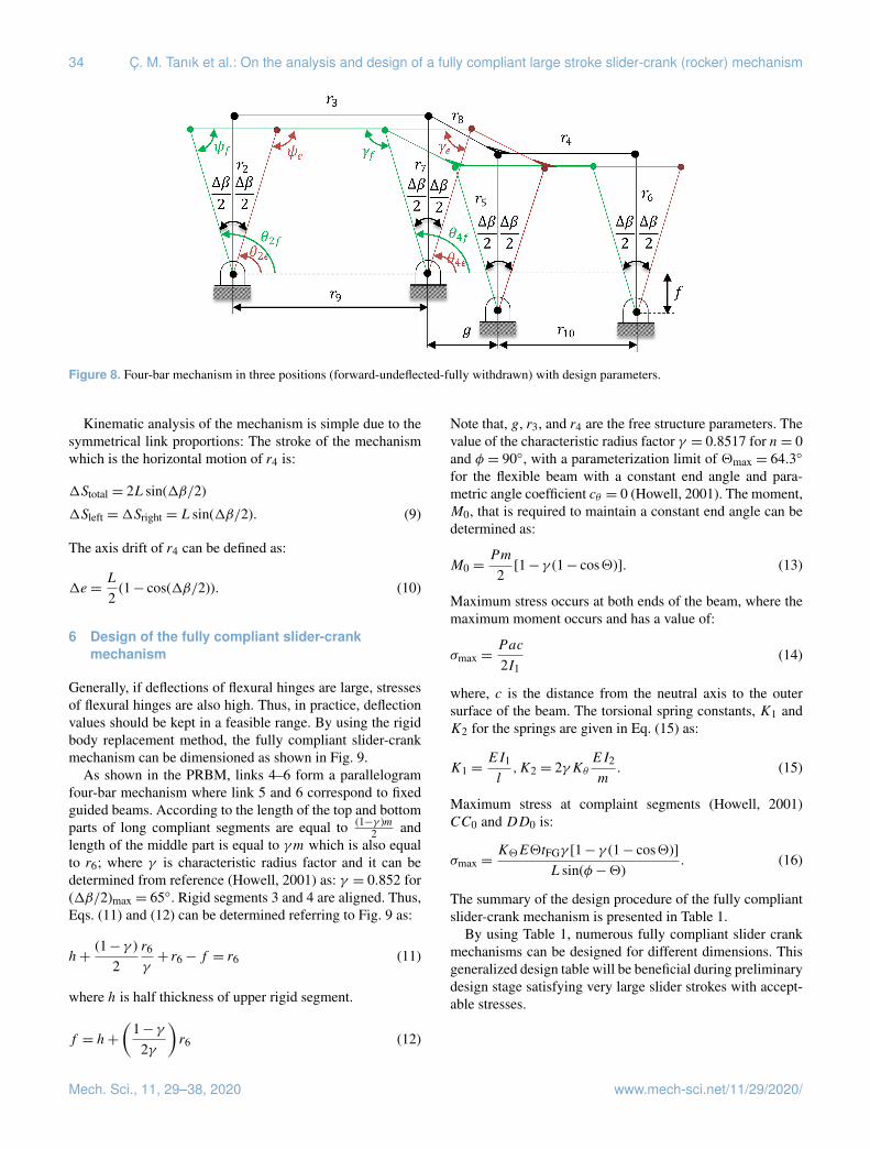
Figure 8. Four-bar mechanism in three positions (forward-undeflected-fully withdrawn) with design parameters.
Kinematic analysis of the mechanism is simple due to thesymmetrical link proportions: The stroke of the mechanismwhich is the horizontal motion of r4 is:
1Stotal = 2Lsin(1β/2)
1Sleft =1Sright = Lsin(1β/2). (9)
The axis drift of r4 can be defined as:
1e =L
2(1− cos(1β/2)). (10)
6 Design of the fully compliant slider-crankmechanism
Generally, if deflections of flexural hinges are large, stressesof flexural hinges are also high. Thus, in practice, deflectionvalues should be kept in a feasible range. By using the rigidbody replacement method, the fully compliant slider-crankmechanism can be dimensioned as shown in Fig. 9.
As shown in the PRBM, links 4–6 form a parallelogramfour-bar mechanism where link 5 and 6 correspond to fixedguided beams. According to the length of the top and bottomparts of long compliant segments are equal to (1−γ )m
2 andlength of the middle part is equal to γm which is also equalto r6; where γ is characteristic radius factor and it can bedetermined from reference (Howell, 2001) as: γ = 0.852 for(1β/2)max = 65◦. Rigid segments 3 and 4 are aligned. Thus,Eqs. (11) and (12) can be determined referring to Fig. 9 as:
h+(1− γ )
2r6
γ+ r6− f = r6 (11)
where h is half thickness of upper rigid segment.
f = h+
(1− γ
2γ
)r6 (12)
Note that, g, r3, and r4 are the free structure parameters. Thevalue of the characteristic radius factor γ = 0.8517 for n= 0and φ = 90◦, with a parameterization limit of 2max = 64.3◦
for the flexible beam with a constant end angle and para-metric angle coefficient cθ = 0 (Howell, 2001). The moment,M0, that is required to maintain a constant end angle can bedetermined as:
M0 =Pm
2[1− γ (1− cos2)]. (13)
Maximum stress occurs at both ends of the beam, where themaximum moment occurs and has a value of:
σmax =Pac
2I1(14)
where, c is the distance from the neutral axis to the outersurface of the beam. The torsional spring constants, K1 andK2 for the springs are given in Eq. (15) as:
K1 =EI1
l,K2 = 2γKθ
EI2
m. (15)
Maximum stress at complaint segments (Howell, 2001)CC0 and DD0 is:
σmax =K2E2tFGγ [1− γ (1− cos2)]
Lsin(φ−2). (16)
The summary of the design procedure of the fully compliantslider-crank mechanism is presented in Table 1.
By using Table 1, numerous fully compliant slider crankmechanisms can be designed for different dimensions. Thisgeneralized design table will be beneficial during preliminarydesign stage satisfying very large slider strokes with accept-able stresses.
Mech. Sci., 11, 29–38, 2020 www.mech-sci.net/11/29/2020/
Ç. M. Tanık et al.: On the analysis and design of a fully compliant large stroke slider-crank (rocker) mechanism 35
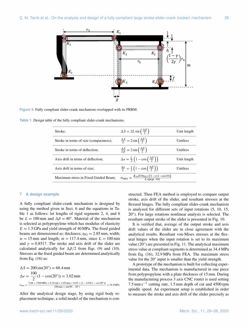
Figure 9. Fully compliant slider-crank mechanism overlapped with its PRBM.
Table 1. Design table of the fully compliant slider-crank mechanisms.
Stroke; 1S = 2Lsin(1β2
)Unit length
Stroke in terms of size (compactness); 1SL= 2sin
(1β2
)Unitless
Stroke in terms of deflection; 1SLβ= 2sin
(1β2
)Unitless
Axis drift in terms of deflection; 1e = L2
(1− cos
(1β2
))Unit length
Axis drift in terms of size; 1eL=
12
(1− cos
(1β2
))Unitless
Maximum stress in Fixed Guided Beam; σmax =K2E2tFGγ [1−γ (1−cos2)]
Lsin(φ−2)
7 A design example
A fully compliant slider-crank mechanism is designed byusing the method given in Sect. 6 and the equations in Ta-ble 1 as follows: let lengths of rigid segments 2, 4, and 6be L= 100 mm and 1β = 40◦. Material of the mechanismis selected as polypropylene which has modulus of elasticityE = 1.5 GPa and yield strength of 40 MPa. The fixed guidedbeams are dimensioned as: thickness; tFG = 2.85 mm, width;w = 15 mm and length; m= 117.4 mm, since L= 100 mmand γ = 0.8517. The stroke and axis drift of the slider arecalculated analytically for 1β/2 from Eqs. (9) and (10).Stresses at the fixed guided beam are determined analyticallyfrom Eq. (16) as:
1S = 200sin(20◦)= 68.4mm
1e =1002
(1− cos(20◦))= 3.02mm
σmax =2.68× 1500MPa× 0.35 rad× 2.85mm× 0.85× [1− 0.85(1− cos20◦)]
100mm× sin(90− 20◦)= 34.4MPa.
After the analytical design stage, by using rigid body re-placement technique, a solid model of the mechanism is con-
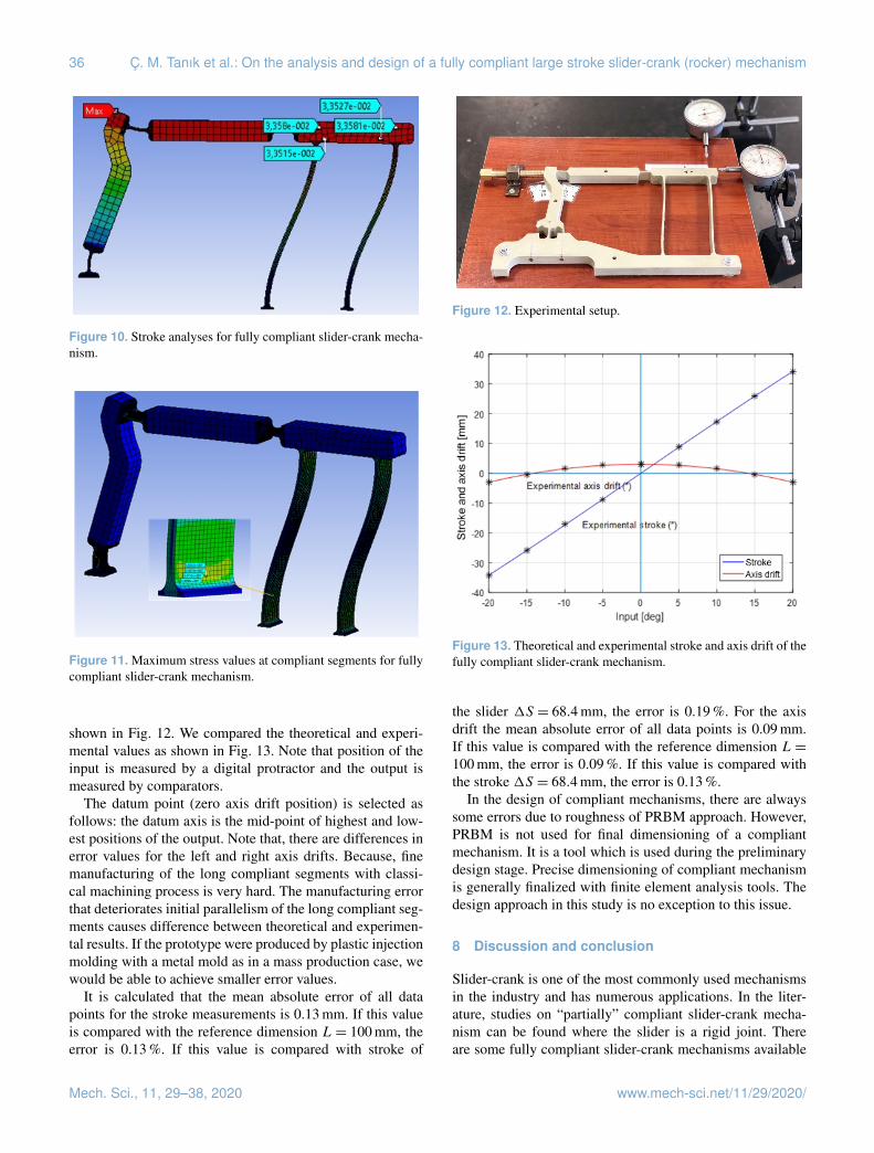
structed. Then FEA method is employed to compare outputstroke, axis drift of the slider, and resultant stresses at theflexural hinges. The fully compliant slider-crank mechanismis analyzed for different sets of input rotations (5, 10, 15,20◦). For large rotations nonlinear analysis is selected. Theresultant output stroke of the slider is presented in Fig. 10.
It is verified that, average of the output stroke and axisdrift values of the slider are in close agreement with theanalytical results. Resultant von-Mises stresses at the flex-ural hinges when the input rotation is set to its maximumvalue (20◦) are presented in Fig. 11. The analytical maximumstress value at compliant segments is determined as 34.4 MPafrom Eq. (16), 32.9 MPa from FEA. The maximum stressvalue for the 20◦ input is smaller than the yield strength.
A prototype of the mechanism is built for collecting exper-imental data. The mechanism is manufactured in one piecefrom polypropylene with a plate thickness of 15 mm. Duringthe manufacturing process 3 axis CNC router is used setting7.5 mm s−1 cutting rate, 1.5 mm depth of cut and 4500 rpmspindle speed. An experiment setup is established in orderto measure the stroke and axis drift of the slider precisely as
www.mech-sci.net/11/29/2020/ Mech. Sci., 11, 29–38, 2020
36 Ç. M. Tanık et al.: On the analysis and design of a fully compliant large stroke slider-crank (rocker) mechanism
Figure 10. Stroke analyses for fully compliant slider-crank mecha-nism.
Figure 11. Maximum stress values at compliant segments for fullycompliant slider-crank mechanism.
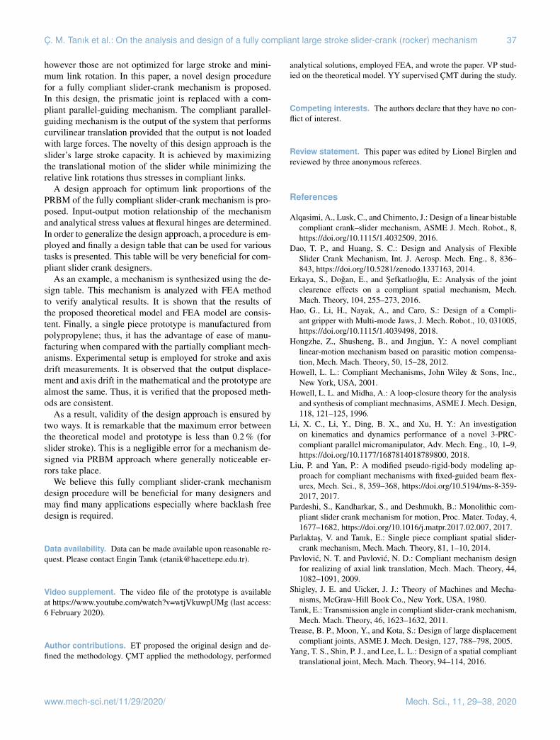
shown in Fig. 12. We compared the theoretical and experi-mental values as shown in Fig. 13. Note that position of theinput is measured by a digital protractor and the output ismeasured by comparators.
The datum point (zero axis drift position) is selected asfollows: the datum axis is the mid-point of highest and low-est positions of the output. Note that, there are differences inerror values for the left and right axis drifts. Because, finemanufacturing of the long compliant segments with classi-cal machining process is very hard. The manufacturing errorthat deteriorates initial parallelism of the long compliant seg-ments causes difference between theoretical and experimen-tal results. If the prototype were produced by plastic injectionmolding with a metal mold as in a mass production case, wewould be able to achieve smaller error values.
It is calculated that the mean absolute error of all datapoints for the stroke measurements is 0.13 mm. If this valueis compared with the reference dimension L= 100 mm, theerror is 0.13 %. If this value is compared with stroke of
Figure 12. Experimental setup.
Figure 13. Theoretical and experimental stroke and axis drift of thefully compliant slider-crank mechanism.
the slider 1S = 68.4 mm, the error is 0.19 %. For the axisdrift the mean absolute error of all data points is 0.09 mm.If this value is compared with the reference dimension L=100 mm, the error is 0.09 %. If this value is compared withthe stroke 1S = 68.4 mm, the error is 0.13 %.
In the design of compliant mechanisms, there are alwayssome errors due to roughness of PRBM approach. However,PRBM is not used for final dimensioning of a compliantmechanism. It is a tool which is used during the preliminarydesign stage. Precise dimensioning of compliant mechanismis generally finalized with finite element analysis tools. Thedesign approach in this study is no exception to this issue.
8 Discussion and conclusion
Slider-crank is one of the most commonly used mechanismsin the industry and has numerous applications. In the liter-ature, studies on “partially” compliant slider-crank mecha-nism can be found where the slider is a rigid joint. Thereare some fully compliant slider-crank mechanisms available
Mech. Sci., 11, 29–38, 2020 www.mech-sci.net/11/29/2020/
Ç. M. Tanık et al.: On the analysis and design of a fully compliant large stroke slider-crank (rocker) mechanism 37
however those are not optimized for large stroke and mini-mum link rotation. In this paper, a novel design procedurefor a fully compliant slider-crank mechanism is proposed.In this design, the prismatic joint is replaced with a com-pliant parallel-guiding mechanism. The compliant parallel-guiding mechanism is the output of the system that performscurvilinear translation provided that the output is not loadedwith large forces. The novelty of this design approach is theslider’s large stroke capacity. It is achieved by maximizingthe translational motion of the slider while minimizing therelative link rotations thus stresses in compliant links.
A design approach for optimum link proportions of thePRBM of the fully compliant slider-crank mechanism is pro-posed. Input-output motion relationship of the mechanismand analytical stress values at flexural hinges are determined.In order to generalize the design approach, a procedure is em-ployed and finally a design table that can be used for varioustasks is presented. This table will be very beneficial for com-pliant slider crank designers.
As an example, a mechanism is synthesized using the de-sign table. This mechanism is analyzed with FEA methodto verify analytical results. It is shown that the results ofthe proposed theoretical model and FEA model are consis-tent. Finally, a single piece prototype is manufactured frompolypropylene; thus, it has the advantage of ease of manu-facturing when compared with the partially compliant mech-anisms. Experimental setup is employed for stroke and axisdrift measurements. It is observed that the output displace-ment and axis drift in the mathematical and the prototype arealmost the same. Thus, it is verified that the proposed meth-ods are consistent.
As a result, validity of the design approach is ensured bytwo ways. It is remarkable that the maximum error betweenthe theoretical model and prototype is less than 0.2 % (forslider stroke). This is a negligible error for a mechanism de-signed via PRBM approach where generally noticeable er-rors take place.
We believe this fully compliant slider-crank mechanismdesign procedure will be beneficial for many designers andmay find many applications especially where backlash freedesign is required.
Data availability. Data can be made available upon reasonable re-quest. Please contact Engin Tanık ([email protected]).
Video supplement. The video file of the prototype is availableat https://www.youtube.com/watch?v=wtjVkuwpUMg (last access:6 February 2020).
Author contributions. ET proposed the original design and de-fined the methodology. ÇMT applied the methodology, performed
analytical solutions, employed FEA, and wrote the paper. VP stud-ied on the theoretical model. YY supervised ÇMT during the study.
Competing interests. The authors declare that they have no con-flict of interest.
Review statement. This paper was edited by Lionel Birglen andreviewed by three anonymous referees.
References
Alqasimi, A., Lusk, C., and Chimento, J.: Design of a linear bistablecompliant crank–slider mechanism, ASME J. Mech. Robot., 8,https://doi.org/10.1115/1.4032509, 2016.
Dao, T. P., and Huang, S. C.: Design and Analysis of FlexibleSlider Crank Mechanism, Int. J. Aerosp. Mech. Eng., 8, 836–843, https://doi.org/10.5281/zenodo.1337163, 2014.
Erkaya, S., Dogan, E., and Sefkatlıoglu, E.: Analysis of the jointclearence effects on a compliant spatial mechanism, Mech.Mach. Theory, 104, 255–273, 2016.
Hao, G., Li, H., Nayak, A., and Caro, S.: Design of a Compli-ant gripper with Multi-mode Jaws, J. Mech. Robot., 10, 031005,https://doi.org/10.1115/1.4039498, 2018.
Hongzhe, Z., Shusheng, B., and Jıngjun, Y.: A novel compliantlinear-motion mechanism based on parasitic motion compensa-tion, Mech. Mach. Theory, 50, 15–28, 2012.
Howell, L. L.: Compliant Mechanisms, John Wiley & Sons, Inc.,New York, USA, 2001.
Howell, L. L. and Midha, A.: A loop-closure theory for the analysisand synthesis of compliant mechnasims, ASME J. Mech. Design,118, 121–125, 1996.
Li, X. C., Li, Y., Ding, B. X., and Xu, H. Y.: An investigationon kinematics and dynamics performance of a novel 3-PRC-compliant parallel micromanipulator, Adv. Mech. Eng., 10, 1–9,https://doi.org/10.1177/1687814018789800, 2018.
Liu, P. and Yan, P.: A modified pseudo-rigid-body modeling ap-proach for compliant mechanisms with fixed-guided beam flex-ures, Mech. Sci., 8, 359–368, https://doi.org/10.5194/ms-8-359-2017, 2017.
Pardeshi, S., Kandharkar, S., and Deshmukh, B.: Monolithic com-pliant slider crank mechanism for motion, Proc. Mater. Today, 4,1677–1682, https://doi.org/10.1016/j.matpr.2017.02.007, 2017.
Parlaktas, V. and Tanık, E.: Single piece compliant spatial slider-crank mechanism, Mech. Mach. Theory, 81, 1–10, 2014.
Pavlovic, N. T. and Pavlovic, N. D.: Compliant mechanism designfor realizing of axial link translation, Mech. Mach. Theory, 44,1082–1091, 2009.
Shigley, J. E. and Uicker, J. J.: Theory of Machines and Mecha-nisms, McGraw-Hill Book Co., New York, USA, 1980.
Tanık, E.: Transmission angle in compliant slider-crank mechanism,Mech. Mach. Theory, 46, 1623–1632, 2011.
Trease, B. P., Moon, Y., and Kota, S.: Design of large displacementcompliant joints, ASME J. Mech. Design, 127, 788–798, 2005.
Yang, T. S., Shin, P. J., and Lee, L. L.: Design of a spatial complianttranslational joint, Mech. Mach. Theory, 94–114, 2016.
www.mech-sci.net/11/29/2020/ Mech. Sci., 11, 29–38, 2020

38 Ç. M. Tanık et al.: On the analysis and design of a fully compliant large stroke slider-crank (rocker) mechanism
Yu, Y. Q., Zhu, S. K., Xu, Q. P., and Zhou, P.: Anovel model of large deflection beams with combined endloads in compliant mechanisms, Precis. Eng., 43, 395–405,https://doi.org/10.1016/j.precisioneng.2015.09.003, 2016.
Zhao, H., Han, Z., Zhang, L., and Shusheng, B.: Design of astiffness-adjustable compliant linear-motion mechanism, Precis.Eng., 48, 305–314, 2017.
Mech. Sci., 11, 29–38, 2020 www.mech-sci.net/11/29/2020/