Embed Size (px)
Citation preview

On site ductwork airtightness measurements in standardization
(Revision of EN 12599)
Dr.-Ing. Frank Bitter (WSPLab) Convenor of CEN/TC 156 WG8
TightVent Europe Webinar
25. April 2019
Standard EN 12599
EN 12599: Test procedures and measurement methods to hand over air conditioning and ventilation systems first published in 2000 revised in 2012 applied to ventilation systems in non-residential buildings
Measurements intended to be executed by the installer Scope opened to other purposes in 2012
(„primarily for handing over“) Ductwork leakage (airtightness) introduced in the
standard in 2012 2
Intention:
Verify the fitness of purpose of ventilation systems

EN 12599 – overview on functional measurements
3
Measurement at Total
System
Central System/Appliance Duct
work
Room
Parameters
Type of
Systems/Functions
Additio
nal c
leanliness test
Curr
ent dra
wn a
nd p
ow
er
by the m
oto
r [D
.6]
air
flo
w *
) [D
.1]
air
tem
pera
ture
*)
[D.3
]
pre
ssure
dro
p a
cro
ss
filter [D
.7]
du
ctw
ork
leakag
e t
est
[D.8
]
supply
air
flo
w [D
.1]
exhaust
air
flo
w [D
.1]
supply
air
tem
pera
ture
**)
and a
ir tem
pera
ture
in the
room
[D
.3]
air
hum
idity [D
.4]
sound p
ressure
level
[D.5
]
Indoor
air
velo
city [D
.2]
Ventilation
System
(F) Z 2 1 1 0 1 2 1 2 0 0 2 0
(F) H 2 1 1 1 1 2 1 2 2 0 2 2
(F) C 2 1 1 1 1 2 1 2 2 2 2 2
(F) M/D 2 1 1 1 1 2 1 2 2 1 2 2
Partial air
conditioning
system
(F) HC 2 1 1 1 1 2 1 2 1 2 2 2
(F)
HM/HD/
CM/CD
2 1 1 1 1 2 1 2 1 1 2 2
(F) MD 2 1 1 1 1 2 1 2 2 1 2 2
(F)
HCM/MC
D/CHD/H
MD
2 1 1 1 1 2 1 2 1 1 2 2
Air
conditioning
system
(F)
HCMD
2 1 1 1 1 2 1 2 1 1 2 2
Table 2 — Functional measurements
*) Outdoor air, supply and exhaust air
**) Depending on control principles, if relevant
EN 12599 – airthightness measurements
The airtightness class according to EN 1507 and EN 12237 shall be checked
In large systems the airtightness can only be measured in a part of the system
The measurements shall be performed while the duct is being installed and accessible Additional tests can be necessary after installation in case
of malfunction e.g. excess pressure
Measurement procedure according to the product standards (laboratory testing) Defined test pressure levels
4

5
ductwork airtightness - building process
idea design building/
installation
commis-sioning
operation
handing over
measurements inspections airtightness measurements selection
air tightness class components
EN 12599 EN 16798-17
Idea of Lars-Åke Mattsson
Ductwork airtightness - System
Airtightness classes for the system are defined in EN 16798-3
6
Classification of system air tightness class
Air tightness class Air leakage limit (fmax)
Old New m³ s-1 • m-2
ATC 7 Not classified
ATC 6 0,067 5 x pt0,65 x 10-3
A ATC 5 0,027 x pt0,65 x 10-3
B ATC 4 0,009 x pt0,65 x 10-3
C ATC 3 0,003 x pt0,65 x 10-3
D ATC 2 0,001 x pt0,65 x 10-3
ATC 1 0,000 33 x pt0,65 x 10-3

Measure the airflow and static pressure
Surface area at least 10 m2
Variety of components and ducts (selection of the product range)
Different diameters
L/A ratio 1 - 1,5
7
Measure the airflow and static pressure
sufficiently large section (refers to EN 1507/12237)
Variety of components and ducts determined by the installation („representative selection“)
L/A ratio 1 - 1,5
Ductwork airtightness - components vs. installed systems
EN 1507 / EN 12237 EN 12599
Airtightness of the installed ductwork system is a result of the mounting (e.g. joints)
System can contain different components
Tightness class of the duct components is rarely reached
8
Ductwork airtightness - components vs. installed systems

Revision on EN 12599
EN 12599 is currently under revision
Airtightness is a main subject to be worked on
- Clarification between the airtightness classes of systems and duct components
- Measurement method should be applicable also for inspections
- Take into account requirements of national guidelines
9
Existing national guidelines for airtightness tests
Existing guidelines in European countries will be introduced in the 3 following presentations
10
Presenter Guideline Country
Laurent Bonnière FD 51-767 France
Peter Rogers DW 143 UK
Erik Osterlund VVS & Kyl09 Sweden

DUCTWORK AIRTIGHTNESS IN FRENCH REGULATION AND FD E51-767
TIGHT VENT – AIVC – APRIL 2019
OUTLINE
■ DUCTWORK AIRTIGHTNESS IN FRENCH
REGULATION
■ LEAKAGES – EXAMPLE OF A EP CALCULATION
■ FD E51–767 DUCTWORK TIGHTNESS
MEASUREMENTS

Ductwork Airtightness in French Regulation
In new buildings, the ductwork class is an input data in the Energy Performance calculation (RT2012 : EP Regulation)
No minimum requirement
Impact on heating loads / cooling loads
If a better value than the default value is used in the EP calculation :
a measurement is required to justify Class A, B or C
this measurement has to be performed by a qualified idependant technician
Since 2013, Effinergie + label requires Class A
Database overview Evolution of the number of measurements
Source – CEREMA Database of ductwork
airtightness measurements in France
Non-residential buildings
Multi-family buildings
Single-family buildings
Year of construction
Nu
mb
er o
f m
easu
rem
ents

DUCTWORK LEAKAGES
EXAMPLE OF A EP CALCULATION
Ductwork leakages Example of a EP calculation
Single family house
Source – OCR ( http://ocr-expertise.fr )
CLIMATIC CONDITION : • Zone H1a
FLOOR AREA : • 98 m2
TOTAL LOSS AREA : • 290 m2

Ductwork leakages Example of a EP calculation
Characteristics of the house
Source – OCR ( http://ocr-expertise.fr )
Parois Libellé Système constructif du bâti
Ep.
isolant
(cm)
R
isolants
m².K/W
Plancher bas
Sur Vide-Sanitaire Plancher hourdis isolant
ITR – Polystyrène - Up = 0.27
Plancher haut
Rampant Isolant sous toiture + doublage intérieur
ITR – Laine minérale (λ = 0.040) ITI – Laine minérale (λ = 0.032)
20 + 6 6.9
Paroi verticale
Mur extérieur Doublage intérieur sur maçonnerie
ITI – laine minérale (λ = 0.032) 14 4.38
Paroi vitrée
Cadre Vitrage Uw (W/m².K)
Double vitrage - VR PVC 4/16/4, PE Argon 1,5
Systèmes
Chauffage
Chaudière Gaz
Condensation Rdt : 97.8% Puissance : 24 [kW]
Eau Chaude Sanitaire
Ballon thermodynamique – Air extérieur – 250L
Éclairage
Puissance d’éclairage moyenne = 8 [W/m²] Ventilation
…
Ground floor
Roof
External Wall
Windows
Building enveloppe
Technical equipements
Heating system
Hot water
Lighting system
Ventilation system
Ductwork leakages Example of a EP calculation
Ductwork airtightness is a input data in EP calculation
Source – OCR ( http://ocr-expertise.fr )
Ductwork airtightness class

Ductwork leakages Example of a EP calculation
Source – OCR ( http://ocr-expertise.fr )
MVHR • Nominal air Flow : 105 [m³/h] (max 180 [m³/h])
• Exchanger : 82% Heat Recovery Efficiency
• Supply Ductwork and Extract Ductwork :
25% inside conditioned space
75% outside conditioned space
Ductwork airtightness
Class
Heating [kwhep/m²]
Energy saving
[kwhep/m²] (%)
Default Value 30,6 0 -
A 29,3 1,3 5 %
B 28,6 2,0 7 %
C 28,4 2,2 8 %
Ductwork leakages Example of a EP calculation
Ductwork airtightness Class
Default Value
A
B
C
Default value : No mandatory test
Class A, B or C : Mandatory test
The ductwork airtightness measurement has to be performed :
by a qualified idependant technician (About 100 certified testers according to a national qualification scheme for ductwork testers)
according to the FD E51-767

FD E 51-767
Ventilation for buildings – Ductwork tightness measurements
FD E51-767
FD E51-767 -> National guidance to specify how to use test standards :
On site with various kind of ductwork (different materials, different shapes, …)
Different use of building (non residential building, residential building…)
To take into account the usual operating pressure of the ventilation system
How to sample
How to take into account specific devices (plenum box, flexible sleeve, …)

FD E51-767
EN 12 237 : Ventilation for buildings – Ductworks – Strength and
leakage of circular sheet metal ducts
EN 1507 : Ventilation for buildings – Sheet metal air ducts with
rectangular section – Requirements for strength and leakage
EN 13 403 : Ventilation for buildings – Non-metallic ducts – Ductwork
made from insulation ductboards
EN 12 599 : Ventilation for buildings – Test procedures and
measurement methods to hand over air conditionning and ventilation systems
FD E51-767 refers to :
FD E51-767 Measurement of ductwork surface area :
FD E51-767 refers to : EN 14 239 Ventilation for buildings — Ductwork — Measurement of ductwork surface area
Only for individual system (in residential buildings) it’s also possible to calculate the surface area with another method :
0,1 x Floor area of the dwelling

FD E51-767
Test pressure :
Building Test pressure
Residential Building – Single family houses
± 80 Pa
Residential Building – Multi family building
± 160 Pa
Non Residential Building ± 250 Pa
Non Residential Building if |Pdesign| > |test pressure|+50Pa
Pdesign
Type of ductwork :
Supply air ducts : Positive pressure
Exhaust air ducts : Negative pressure
Use of building :
FD E51-767
How to sample :
Individual system (residential)
o 100 % of ductwork (Exhaust ductwork and Supply ductwork)
Collective system (residential) and non residential system
o All kinds of ducts (size, type of ducts, type of section, type of accessories, …)
AND
o One of those requirements shall be met :
• Case 1 : L/Aj ≥ 1 and Aj > 10 m2 and Aj > 10 %
• Case 2 : At least one whole floor to the ventilation unit and Aj > 10 m2 and Aj > 20%
• Case 3 : At least one whole column to the ventilation unit and Aj > 10 m2 and Aj > 20%

FD E51-767
How to sample :
CASE 2 – example unit
A
: sealed
A : equipment for measuring
: exhaust or supply unit
: sealed
FD E51-767
How to sample :
CASE 3 - example
unit
A : equipment for measuring
: exhaust or suppy unit

FD E51-767
How to sample :
If there are several ventilation units and air handling units
Method of sample selection :
If N ≤ 5, each ductwork have to be tested
If N > 5, number Of ductwork to be tested :
5 + 40% x (N-5)
N : number of unit
FD E51-767
Measuring method – specific devices To Give penalties if some parts can’t be tested to use it for the EP
Calculation
Method to seal off the diffuser (exhaust units / supply units) or the climate beams
1 - 4 Exhaust or supply unit or Climate beams
2 Sealing instead of unit
3 – 5 Plenum box
6 Sealing in the duct
Plenum box included Plenum box not included

FD E51-767
Measuring method – specific devices Method to seal off the connection to the Ventilation unit
1 – 5 Ventilation unit (fan, air handling unit…) 4 – Sealing in the ventilation unit 2 – 6 Flexible sleeve - Connection Ductwork – Ventilation Unit 3 – 7 Ductwork 8 Sealing in the duct
Flexible sleeve included Flexible sleeve not included
FD E51-767
Measuring method – specific devices
Method to seal off – Specific devices – Correction of measured values
Componant Penalties Correction of
measured values Flexible sleeve Climat beam Plenum box
Included Included Included x 1
Not included included Included
x 1,3 Included Not included Included
Included Included Not included
Not included Not included Included
x 1,4 Included Not included Not included
Not included Included Not included
Not included Not included Not included x 1,5

Ductwork Airtightness Measurements: Protocols
25 April 2019
DW/143
Peter Rogers:
BESA Chairman of Ventilation Group Technical Committee.

• With regard to air leakage, the responsibilities for ensuring the achievement of a satisfactory project are divided between the ductwork contractor, production and the on-site installation team. It is essential that there is full co-operation between them.
• Establish with the system designer, client or representative the class of ductwork called for in the project specification.
• Leakage testing is always done under positive pressure even when the ductwork is to operate under negative pressure.
GENERAL
THE DUCTWORK CONTRACTOR

• Ensure that components have been manufactured and sealed in accordance with the design specification.
• Agree with the system designer the test pressure for each section of the installation
• Decide the best way to isolate the installation into test zones.
• Make sure that test points and blanking devices can be reached with minimum difficulty.
• Prepare test sheets giving the information required for each section being tested.
THE DUCTWORK CONTRACTOR
PRODUCTION

• Manufacture components with a good fit to minimize the use of sealant. A poor fit cannot be remedied by the use of additional sealant.
• Seal all longitudinal seams joints.
• Special care must be taken in the fitting of access doors and panels.
• Ductwork must be handled and delivered with care to avoid the danger of breaking the seals.
PRODUCTION
ON SITE INSTALLATION TEAM
• Before installation, inspect all duct sections to make sure that factory applied seals have not been damaged during transit.
• Fix blanking plates or other temporary seal in the positions shown by the ductwork contractor.
• Agree with the client a progressive testing programme.
• Carry out a preliminary test and look for any obvious places where there may be leakage.
• Offer the test section to the client for formal acceptance and signature on the test sheet.
ON SITE INSTALLATION TEAM
• Air leakage testing of low and medium pressure ductwork is not mandatory under BESA DW/144 specification for Sheet Metal Ductwork.
• Air leakage testing of high-pressure ductwork is mandatory under BESA DW/144 specification for sheet metal ductwork.
CLASSIFICATION, AIR LEAKAGE AND TEST PROCEDURES

DUCTWORK CLASSIFICATION AND AIR LEAKAGE LIMITS
• Determine the extent of ductwork to be tested and the method selected.
• Fit blanking devices in accordance with the system test zones.
• The section of ductwork area to be tested shall have an area large enough to enable the test rig to register a measurable leakage.
• Follow the recommendations of the manufacturer of the test equipment and ensure that it has a calibration certificate.
• Due notice of tests shall be given, so that arrangements for witnessing can be made.
• NOTE Testing shall be completed before any insulation or enclosure of the ductwork.
AIR LEAKAGE TESTING PROCEDURE

HINTS ON DUCTWORK LEAKAGE TESTING
EXAMPLE OF COMPLETED TEST SHEET

• ADL2A (new buildings) and ADL2B (existing buildings) state that “Ductwork leakage testing should be carried out in accordance with the procedures set out in BESA DW/144” (refers to DW/143) Specification for Sheet Metal Ductwork.
BUILDING REGULATIONS
• If the system designer considers the testing of medium pressure class ductwork to be unavoidable then it is recommended that random tests are identified.
RANDOM TESTING

• It is generally accepted that in a typical good quality system the leakage from each class of ductwork under operating conditions will be in the region of:
Class A low pressure 6%
Class B medium pressure 3%
Class C high pressure 2%
Class D high pressure 0.5%
SYSTEM LEAKAGE LOSS
• Items of in-line plant items will not normally be included in an air leakage test.
• The ductwork contractor may include such items in the test if the plant item has a manufacturers certificate of conformity for the pressure classification for the system under test.
TESTING OF PLANT ITEMS

AIR LEAKAGE RATES
PERMITTED LEAKAGE AT VARIOUS PRESSURES
Permitted leakage at various pressures

OTHER BESA PUBLICATIONS
Thank you Any questions?
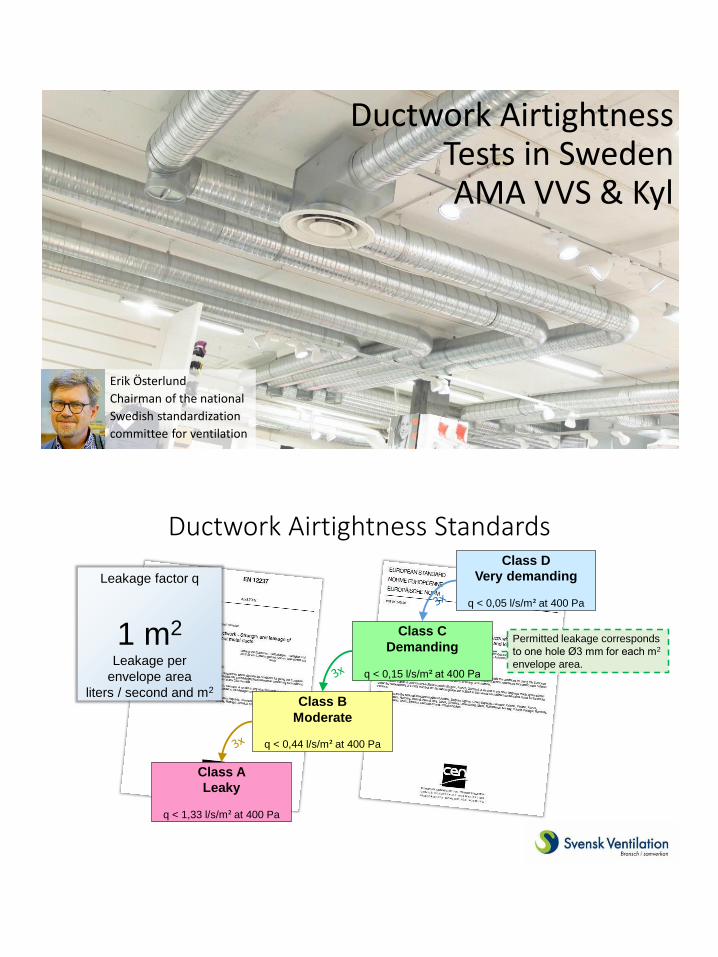
Ductwork Airtightness Tests in Sweden AMA VVS & Kyl
Erik Österlund
Chairman of the national
Swedish standardization
committee for ventilation
Ductwork Airtightness Standards
Class A
Leaky
q < 1,33 l/s/m² at 400 Pa
Class B
Moderate
q < 0,44 l/s/m² at 400 Pa
Class C
Demanding
q < 0,15 l/s/m² at 400 Pa
Class D
Very demanding
q < 0,05 l/s/m² at 400 Pa
Leakage factor q
1 m2
Leakage per
envelope area
liters / second and m2
Permitted leakage corresponds
to one hole Ø3 mm for each m2
envelope area.

AMA = General Description of Materials and Works Allmän Material- och Arbetsbeskrivning
Civil works
Buildings
Electricity
HVACR+plumbing
Administrative
RA = Advice and Guidance
AMA - legal status?
No law! AMA is voluntary.

Correct material Tight? Tight How do
you know?
Check by measuring
Correctly installed
Airtight ductwork?
Check by measuring Tight
Correctly installed Correct material
Divide ductwork in samples for testing. 25 m² recommended sample size 10 m² minimum sample size
Part Y Checks for Air Handling Systems
Third party certified ductwork 10% of circular 20% of rectangular
Non-third party certified:
100% to be tested.
Measure leakage at duty pressure, or
400 Pa default pressure 200 Pa minimum pressure
Tight

How airtight are ducts?
0.00%
0.05%
0.10%
0.15%
0.20%
0.25%
1 2 3 4 5Airflow velocity m/s
Leakage/Total Airflow, Ø1000 mm, 100 Pa
Tightness class A
Tightness class B
Tightness class C
Tightness class D
0%
1%
2%
3%
4%
1 2 3 4 5Airflow velocity m/s
Leakage/Total Airflow, Ø125 mm, 300 Pa
Tightness class A
Tightness class B
Tightness class C
Tightness class D
Class A
Leaky
q < 1,33 l/s/m² at 400 Pa
Class B
Moderate
q < 0,44 l/s/m² at 400 Pa
Class C
Demanding
q < 0,15 l/s/m² at 400 Pa
Class D
Very demanding
q < 0,05 l/s/m² at 400 Pa
Permitted leakage corresponds
to one hole Ø3 mm for each m2
envelope area.
Invisible mistakes can ruin the airtightness class

Airtight ductwork material mounting measurement


![Air Infiltration and Ventilation Centre © INIVE EEIG Ductwork ...This paper aims to complement Ventilation Information Paper (VIP)o1 “Airtightness of ventilation ducts” [12]](https://img.pdfslide.us/doc/110x75/6131cb5e1ecc51586944f5ae/air-infiltration-and-ventilation-centre-inive-eeig-ductwork-this-paper-aims.jpg)


![P187 · Standard EN 12237 [10] for circular ducts and EN 1507 [6] for rectangular ducts. A new standard for airtightness of ductwork components is in preparation: prEN 15727 [14]](https://img.pdfslide.us/doc/110x75/5e7aedd762b3f04aa574925c/p187-standard-en-12237-10-for-circular-ducts-and-en-1507-6-for-rectangular-ducts.jpg)