Embed Size (px)
Citation preview
On preparatory object rotation to adjusthandle orientation for grasping
Lillian Y. Chang Nancy S. Pollard
CMU-RI-TR-08-10
April 2008
Robotics InstituteCarnegie Mellon University
Pittsburgh, Pennsylvania 15213
c© Carnegie Mellon University


AbstractThis study investigates preparatory rotation as a manipulation strategy for grasping objects from different
presented orientations. Participants lifted heavy, handled objects from eight initial orientations under twotask constraints. When object motion was permitted, participants used preparatory rotation to first adjust theobject handle to a desired orientation before lifting. The amount of rotation increased for handle orientationsfurther from the central orientation. When object motion was not permitted, increased upper body joint torquewas required for the direct grasping strategy compared to that for the preparatory rotation strategy. Graspconfiguration and ratings for comfort and naturalness also exhibited similar trends, leading to the conjecturethat both energetic considerations and grasp kinematic considerations may drive the selection of preparatoryrotation.
I


Contents1 Introduction 1
2 Method 32.1 Participants . . . . . . . . . . . . . . . . . . . . . . . . . . . . . . . . . . . . . . . . . . . 32.2 Procedure . . . . . . . . . . . . . . . . . . . . . . . . . . . . . . . . . . . . . . . . . . . . 3
3 Data analysis 5
4 Results 84.1 Timing . . . . . . . . . . . . . . . . . . . . . . . . . . . . . . . . . . . . . . . . . . . . . . 94.2 Object liftoff posture . . . . . . . . . . . . . . . . . . . . . . . . . . . . . . . . . . . . . . 94.3 Perceptual rating . . . . . . . . . . . . . . . . . . . . . . . . . . . . . . . . . . . . . . . . 15
5 Discussion 18
6 Acknowledgments 19
III


1 Introduction
The activities of daily living require manipulating a wide variety of differently-shaped objects. To success-fully complete many goal-oriented tasks in unstructured environments, humans must be able to adapt basicmanipulation skills in response to novel conditions such as changes in the object shape, weight, and place-ment in the environment. Several studies have focused on finding underlying invariant characteristics ofhuman reaching and grasping motor control, such as the timing coordination of hand transport with handpre-shaping during reaching (Jeannerod, 1981) or the existence of motor synergies in hand force regulation(Li et al., 1998; Latash et al., 1998). Another aspect of interest is how humans adjust manipulation strategiesin response to different parameters for a given class of tasks. For example, Johansson (1996) investigatedhow finger grip forces are adjusted in response to surface friction.
One body of previous research has investigated how body posture and hand orientation in reaching move-ments are related to manipulation task parameters. Bongers et al. (2004) reported that the stopping distancein a reaching manipulation task was dependent on the tool-use posture, tool length, and tool weight. Work byStelmach et al. (1994) and Desmurget et al. (1996) showed that wrist angle and trajectory changed accordingto the orientation of the cylindrical object placed in the same position. Similarly, Rand & Stelmach (2005)studied how arm transport duration and distance in reach-to-grasp movements differed for starting forearmpositions with supination or pronation.
In addition, Rosenbaum and colleagues have investigated the selection of hand grips for a variety ofhandle transport and handle rotation tasks where a cylinder is grasped and placed at several different goalconfigurations (Rosenbaum et al., 1990, 1992, 1993). This has led to several inquiries testing how perceivedend-state comfort of a task affects the choice of initial hand grasps in object transport tasks (Rosenbaum et al.,1992; Short & Cauraugh, 1997; Zhang & Rosenbaum, 2008). In recent work, Rosenbaum & Gaydos (2008)present a relative cost approach for evaluating the movement costs for tasks such as object-positioning andobject-rotation.
Our experiments are the first, to our knowledge, to explore what we refer to as preparatory manipulationstrategies. Preparatory manipulation occurs whenever the interaction first adjusts the object configuration inthe workspace prior to grasping (Fig. 1). This approach takes advantage of the object’s movability on thesurface to effectively change the intermediate task parameters. In such cases, the action in anticipation ofa grasping task not only consists of changes in the manipulator’s posture such as arm reaching movementand hand pre-shaping, but it also includes changes in the object configuration in the environment prior tograsping. This study specifically examines object rotation as a preparatory manipulation strategy for liftingheavy objects from different presented object orientations. Departing from the previous studies (Rand &Stelmach, 2005; Rosenbaum et al., 1992) on manipulation of lightweight objects, we chose to investigatelifting of heavy objects since we believe preparatory manipulation is most relevant to more demanding tasks.
The aims of this study are to quantify the consistency of object rotation as a preparatory strategy and toexamine possible criteria that the strategy may optimize. The preparatory adjustment may allow a novel ordifficult task to be transformed to a familiar, easier one. In the case of lifting heavy objects, pre-rotating theobject prior to lifting may move the handle to a familiar canonical configuration. The canonical orientation
Figure 1: Preparatory manipulation adjusts the object configuration in the workspace prior to grasping. Oneexample of preparatory manipulation is preparatory object rotation, shown here for a handled pan, where theobject orientation is adjusted before grasping.
1
may be preferable to the orientation initially presented because it requires less exertion in the lifting posture,allows more stable grasps of the handle, or is perceived to be more comfortable.
Previous studies have examined similar qualities as possible optimization criteria for motor control. Exer-tion or energy as measured by the magnitude of joint torques has been used for simulating walking behavior(Chow & Jacobson, 1971), predicting postures for sagittal plane lifting (Dysart & Woldstad, 1996; Changet al., 2001), and modeling upper extremity postures for reaching tasks (Engelbrecht, 1997). Several studies(Fischman, 1998; Short & Cauraugh, 1997; Rosenbaum et al., 1992) have investigated end-state comfort forhand grasps of elongated objects. It is possible the perceived grasp comfort may be related to the grasp loca-tion on the object, as work by Turvey et al. (1999) found that object inertia asymmetry was a factor in weightperception.
In our study, we investigate how the amount of preparatory object rotation changed in response to eightdifferent object orientations on a horizontal surface. Other metrics computed from the body posture at timeof object liftoff included the joint torques at the torso, shoulder, elbow, and wrist, and the grasp configurationwith respect to the object handle. In addition, participants rated the lifting task trials for comfort and natu-ralness. All of the response variables were compared between different task constraints where preparatoryobject rotation was permitted or not permitted in the verbal task instructions.
2

2 Method
2.1 Participants
Ten right-handed adults (5 male, 5 female) volunteered for the study (age = 26.7 ± 3.5 years [mean ±
standard deviation], height = 167.1 ± 9.1 cm, weight = 58.7 ± 10.9 kg). All participants signed informedconsent forms approved by the Institutional Review Board.
2.2 Procedure
Participants performed the object lifting tasks in a kitchen counter top setting (Fig. 2). The object startposition was located on the right side counter area. The object goal area was located 77 cm to the left of thestart position and was marked by a circular cover over the bottom left stove burner. At the start position, theobject was presented in one of eight possible orientations, indicated by the direction of the object handle. Inthe baseline orientation, the handle directly faces the participant, and the remaining 7 orientations spanned afull 360 degrees in 45 degree increments. The two handled objects tested for all ten participants were a largeplastic water jug and a cast iron frying pan, both without lids (Fig. 3). The objects were filled with water fora total mass of 3.4 kg for the jug and 1.5 kg for the pan.
Kinematic data for the participant and objects were recorded at 120 Hz using a Vicon camera system(Vicon Motion Systems, Los Angeles, California, USA). Motion of the full body, including hands and fingers,was tracked by 80 reflective markers attached to the participant. The marker set included 4 markers on thehips, 8 markers on the torso, 7 markers on the arm, 6 markers on the hand dorsum, and 10 markers on thefingers. Prior to the lifting tasks, a calibration trial was recorded where the participant exercised the range ofmotion for all joints. In the following experiments, each object was tracked by 5 attached markers.
In each lifting task trial, the participant started facing the counter with toes at a distance of 78 cm from thecounter edge, such that the object was outside of arm’s reach. The participants arms were held out to the sidewith the hands resting prone at table height, which improved the tracking of the hand markers by the camerasystem. For all trials, the task goal was to move the object to the goal position without spilling any water. Nospecific object orientation was required at the goal. Participants were instructed to perform the transport taskat a self-selected speed with no time constraints. We investigated the performance of the transport task for the
object start
object goal
participant start
77 cm
78 cm
a
1
2
3
6
5
4
7
8
object
b
Figure 2: General layout of the experimental setting. (a) Participants started in a standing position facing thecountertop setting. Participants transported the handled objects from the start position to the goal positionwith their right hand. (b) In each trial, the handled object started in one of eight orientations defined by thehandle direction. In the figure, the handled object is in orientation 1, the baseline orientation.
3

18 cm
18 cm
24 cm
x
z
y
z
a
45 cm
27 cm
9 cm
x
y
y
z
b
x
y
x
z
c
Figure 3: Participants transported two different handled objects filled with water, (a) an uncapped water jugand (b) a cast iron cooking pan. The coordinate systems located at the object handles provide a referenceframe for measuring the (c) hand dorsum configuration during the object grasp.
two objects over the 8 possible object starting orientations. Each set of 8 trials started with the object handlein the baseline handle orientation, and subsequent 7 trials progressed clockwise in the handle orientation.
The experiment consisted of three phases to examine three types of task scenarios. The first phase servedas practice trials to familiarize the participants with the task setting. Participants were instructed to completethe transport task with no restrictions, using either or both hands as desired. In the first set of 8 trials,participants transported the filled water jug from the 8 initial handle orientations. Then, in the second set of8 trials, the filled frying pan was transported from the 8 initial handle orientations. At the end of the practicephase, participants rated the 16 different lifting tasks for comfort and naturalness on a scale of 1 to 9.
The second phase investigated unimanual lifting performance in response to the different object handleorientations. The purpose of this phase, as the main portion of the experiment, was to observe to what extentobject preparatory adjustment would be used as a strategy to compensate for changes in object orientation.Participants were instructed to complete the transport task using only their right hand to contact the object.Besides this unimanual constraint, there were no restrictions on the task performance. The verbal instructionsdid not suggest preparatory object motion as a strategy, as it was our intent to observe what strategies theparticipants would naturally select. Two sets of 8 trials were completed for the jug to obtain a measure ofperformance repeatability. Next, two sets of 8 trials were completed for the pan. As before, participants ratedthe 16 unimanual task conditions for comfort and naturalness.
The final phase tested how participants would respond to different object handle orientations in the ab-sence of preparatory object adjustment on the counter surface. The task performances from this third phaseprovide a reference measurement for analyzing the object adjustment motion in the second phase. Partici-pants were instructed to transport the object using only right hand contact and without any lateral sliding onthe surface prior to lifting the object from the start position. Participants were given the option of aborting atrial at any time during the task if they could not complete the task under the given constraints. The first setof 8 trials was completed for the jug, and the second set of 8 trials was completed for the pan. The 16 taskswere rated for comfort and naturalness at the end of the phase.
The experiment required approximately 90 minutes for a single participant.
4

3 Data analysis
Kinematic skeletal models for each participant were fit to the recorded marker trajectories as follows. Thegeneric skeletal template modeled the lower back, shoulder, elbow, and wrist as spherical joints with threerotational degrees of freedom. An individual skeleton was automatically fit to the manually-labeled range ofmotion data using the Vicon IQ software’s subject calibration function (Vicon Motion Systems, Los Angeles,California, USA). For the lifting task trials, the joint center locations of the individual skeletal model werefitted to the labeled marker trajectories automatically using the Vicon IQ software’s kinematic fit function.Gaps in the marker trajectories due to occlusions, which occurred frequently for the lower body markers andhand dorsum markers, were not manually reconstructed. Due to the frequent occlusions, reliable joint centerlocations were obtained only for the torso, shoulder, elbow, wrist, and finger knuckle joints.
In each trial, four time points represent key events in the task performance. The key time points weredetermined by the following events: (1) initial body movement, (2) initial object contact, (3) object liftofffrom the surface, and (4) object arrival at the goal. These mark the start and end points of three segments ofthe motion (Table 1). First, reaching and approach to the object start with the initial body movement fromthe participant’s start position and ends when the object is first contacted (T1). Then, object manipulationand grasping occur between the initial object contact and the object liftoff from the surface (T2). Finally,object transport starts after the object liftoff and ends on object arrival at the goal position (T3). The fourkey time points were estimated automatically from the trial marker trajectories based on manually-selectedthresholds. Initiation of body movement was estimated as the first frame where the average body markerdistance from the starting pose exceeded 1 cm. In the absence of tactile sensor data for either the participant’shand or the object surface, we estimated initial object contact from the initial object movement. As withbody movement, initiation of object movement was detected when the average object marker distance from
Table 1: Response metrics observed for each trial where the participant lifted and transported a handled objectfrom the presented object start orientation. The linear mixed-effects models tested the differences in each ofthe metrics between the unimanual constraint trials and object motion constraint trials.
Response metric Computation notes
Timing
Approach and reaching, T1 Initiation of body movement to initiation of object movementManipulation and grasping, T2 Initiation of object movement to object lift off from surfaceObject transport, T3 Object lift off surface to object arrival at goal positionTotal time, T1 + T2 + T3 Initiation of body movement to object arrival at goal position
Object liftoff posture
Object rotation Angle change at liftoff from initial orientation, on surface planeJoint torque load Sum of squared torques over torso, shoulder, elbow, and wristGrasp orientation Angle of single rotation between hand frame and object frameGrasp location Distance between origins of hand frame and object frame
Perceptual rating
Comfort Self-reported on scale of 1 to 9 after trial setNaturalness Self-reported on scale of 1 to 9 after trial set
5

the starting configuration exceeded 1 cm. Object liftoff from the surface was marked when the verticalcoordinate of one object marker exceeded 1 cm change from the starting vertical position. Object arrival atthe goal position was marked when the vertical coordinate of one object marker fell within 1 cm of the endingvertical position. The time durations for the reaching, object manipulation, and object transport segments ofthe task are determined from the differences between the four key time points. Total task duration is the sumof the three segment durations.
The third key time point, object liftoff from the surface, is the focus of our data analysis. Four metrics werecomputed from the participant’s body pose at the liftoff time frame: object rotation, joint torque load, grasporientation, and grasp location (Table 1). Object rotation was measured as the change in angular orientationwith respect to the horizontal plane between the object’s starting orientation and the object orientation inthe liftoff frame. We computed the absolute amount of rotation so that there was no distinction betweenclockwise or counterclockwise rotation. Upper body joint torques were estimated from the liftoff body poseas follows. The segment mass of the torso, right upper arm, right forearm, and right hand were estimated asa fraction of total body mass according to the anthropomorphic data reported in Clauser et al. (1969) (Table2). Locations of the segment center of mass were also estimated as a fraction of segment length accordingto the results of Clauser et al. (1969) (Table 2). Given the fitted joint center locations for the lower back,shoulder, elbow, and wrist, joint torques were calculated from the loads due to distal limb segment weightand the object weight. The four joint torques were combined into a single metric of the sum of squaredjoint torques. The configuration of the hand dorsum coordinate system was then computed with respect tothe reference coordinate system attached to the object handle (Fig. 3). The grasp orientation is measured asthe angle magnitude of the single axis-angle rotation which would align the hand dorsum coordinate systemto the object handle coordinate system. The grasp location is measured as the distance between the handcoordinate system origin at the proximal end of the third metacarpal and the object coordinate system originat the base of the handle (Fig. 3).
The overall set of dependent variables examined in this study were difference in metrics (Table 1) be-tween the tasks with the unimanual constraint (second phase) and the tasks with the additional object motionconstraint (third phase). The difference in metrics were computed between matched pairs of trials performedby the same participant on the same object for the same initial handle configuration, with only a difference inthe task constraint. The differences were computed for the two sets (repetitions) of 8 trials per object in theunimanual constraint phase with respect to the single set of 8 trials per object in the motion constraint phase.In addition to the metrics for the liftoff pose, the differences in time duration, comfort rating, and naturalnessratings were computed between the unimanual and motion constraint phases.
We analyzed the difference metrics with linear mixed-effect (LME) models (Verbeke & Molenberghs,2000) using the NLME package (Pinheiro & Bates, 2000) for R 2.6.2 (R Development Core Team, 2008).Our study contains repeated measures because each participant performs the lifting task for both objects and
Table 2: Parameters used for joint torque load estimation, based on results reported by Clauser et al. (1969).The location of the center of mass of each segment is estimated from the fraction of the segment lengthdefined by joints at the segment ends. The joint locations were obtained from the kinematic skeleton fitted tothe marker position data at the object liftoff time frame.
Segment mass(percent body mass)
Joints defining segment length Center of mass, C
(percent length, AC/AB)Body segment Endpoint A Endpoint B
Torso 50.7 sternoclavicular lower back 38.0Right upper arm 2.6 shoulder elbow 51.3Right forearm 1.6 elbow wrist 39.0Right hand 0.7 middle knuckle wrist 18.0
6

all 8 orientations. Thus the observations are not independent, and we cannot use a standard linear analysisof variance (ANOVA) to correctly test the significance of the explanatory variables. LME models addressthe correlated errors from dependent observations by including random effects in addition to the mean fixedeffects. In our study, the data is grouped by participant such that the LME model accounts for the correlationbetween the repeated observations for each participant. LME models can also handle missing observationswithout discarding all observations for one participant. This allowed us to include data from participants evenif the lifting task was not completed for all handle orientations.
The explanatory variables available as fixed effects for the LME models included the object, the initialhandle orientation, the square of the initial handle orientation, and the task repetition (either the first or sec-ond observation) of the unimanual constraint trials. Model selection was used to determine an appropriatecombination of available explanatory variables for modeling each dependent variable. In the model selec-tion process for a given dependent variable, multiple LME models were fitted for different combinations ofpossible explanatory variables. Using a standard statistical method to favor better data fits without using toomany model parameters, we selected the model with the lowest Bayesian Information Criterion (BIC) score(Pinheiro & Bates, 2000) as the final LME model for that dependent variable. The t-test results for the finalLME model indicate which explanatory variables were statistically significant as fixed effects. In addition,the significance of each random effect in the final LME model was checked using a likelihood L ratio testcomparing the selected LME to a linear model without the random effect (Pinheiro & Bates, 2000).
Separate LME models were selected for each of the four dependent variables computed from the liftoffpose: difference in object rotation, difference in sum of squared joint torques, difference in hand grasporientation, and difference in hand grasp position. Model selection was also performed to select LME modelsfor the differences in comfort rating and differences in naturalness rating.
7
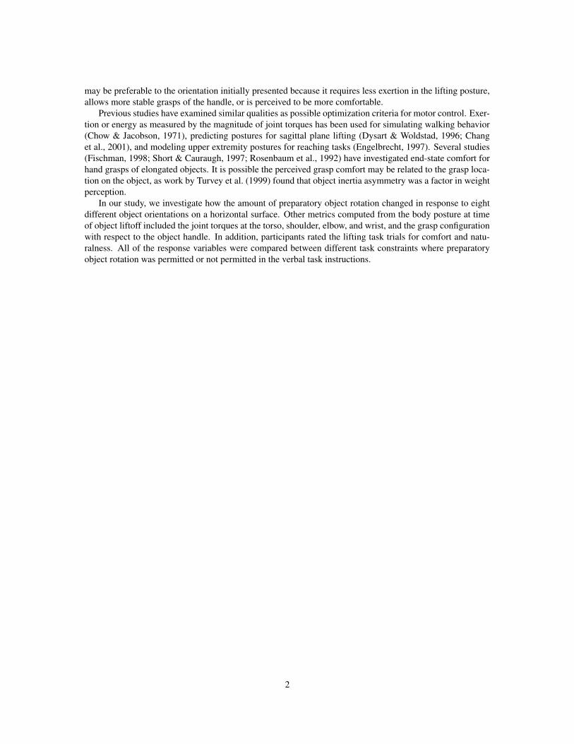
4 Results
When participants were only restricted by the unimanual constraint, they often rotated the object on thecountertop surface to a new orientation before lifting and transporting the object to the goal. The resultingbody poses at object liftoff (Fig. 4) were similar in terms of the upright torso orientation and object handledirected toward the participant. In contrast, when the object rotation strategy was precluded by the objectmotion constraint, the resulting body poses at object liftoff were more varied in the torso orientation andarm configuration. For trials where the object handle faced away from the participant, the torso was oftentilted over the countertop surface with the elbow extended away from body to achieve the grasp of the objecthandle. One participant chose to abort one lifting trial in the object motion constraint phase after grasping
jug liftoff with unimanual constraint pan liftoff with unimanual constraint
orientation 4orientation 5table surface
a
jug liftoff with object motion constraint pan liftoff with object motion constraint
orientation 4orientation 5table surface
b
Figure 4: Visualization of the body postures at object liftoff for a sample subject. Poses are shown for thetrials with initial object orientation 4 and 5, where the handle faced away from the participant. (a) Poses forthe trials with the unimanual constraint. (b) Poses for the trials with the additional object motion constraint.The liftoff poses for the unimanual constraint trials were more similar to each other because the allowedobject motion adjusted the handle direction toward the participant. When object motion was not permitted,the liftoff poses are more varied. In the most extreme cases for initial object orientation 4 and 5, the torso istilted over the countertop and the elbow is held away from the side of the body.
8
and attempting to lift the pan from handle orientation 5 without object motion along the surface.
4.1 TimingDifferences in the timing between the unimanual constraint and object motion constraint trials suggests thatrotation adjustment provides a trade-off between different segments of the movement (Table 3). Out of the320 possible timing difference observations for each motion segment, only 318 could be computed becauseof the missing reference measurement due to the single aborted trial. Object manipulation duration T2between initial object movement and object liftoff, for the unimanual constraint trials was longer than thatin the reference object motion constraint trials for 93% of the 318 time differences, and the mean durationdifference was 139 msec. This is not surprising since we expect object adjustment to require additional timeto only lifting the object. However, the reaching time T1 and object transport time T3 were shorter for theunimanual constraint trials than for the object motion constraint trials for 90% and 81% of the 318 trials,respectively. The mean time differences were -199 msec for reaching and -105 msec for object transport. Inaddition, the total task time, T1 + T2 + T3, from initial body movement to object arrival at the goal positionwas shorter for the unimanual constraint trials for 75% of the 318 trials, with a total mean duration differenceof -165 msec.
4.2 Object liftoff postureThe single aborted trial resulted in 2 missing difference metrics for the response variables computed from theobject liftoff poses. In total there were 318 object rotation difference metrics and 318 joint torque differencemetrics. Occlusions of the hand dorsum markers resulted in additional missing data points for the grasp con-figuration metrics. Overall, there were 296 grasp orientation differences and 307 grasp location differencesanalyzed in the following models.
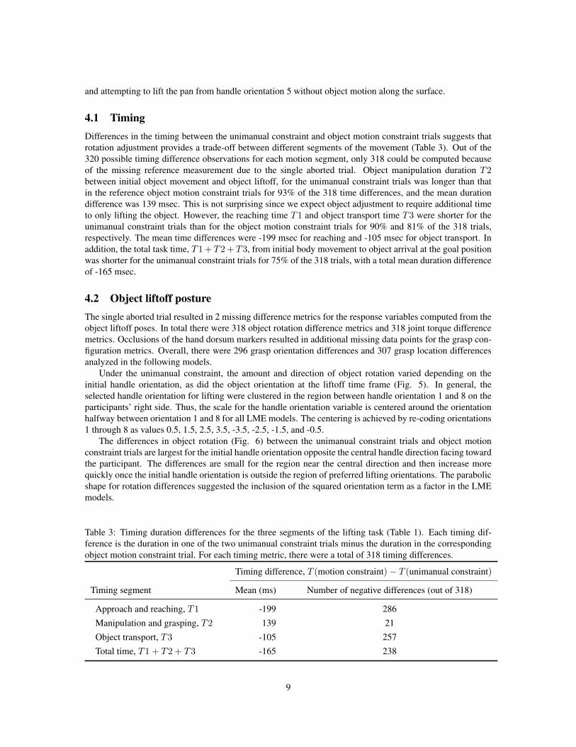
Under the unimanual constraint, the amount and direction of object rotation varied depending on theinitial handle orientation, as did the object orientation at the liftoff time frame (Fig. 5). In general, theselected handle orientation for lifting were clustered in the region between handle orientation 1 and 8 on theparticipants’ right side. Thus, the scale for the handle orientation variable is centered around the orientationhalfway between orientation 1 and 8 for all LME models. The centering is achieved by re-coding orientations1 through 8 as values 0.5, 1.5, 2.5, 3.5, -3.5, -2.5, -1.5, and -0.5.
The differences in object rotation (Fig. 6) between the unimanual constraint trials and object motionconstraint trials are largest for the initial handle orientation opposite the central handle direction facing towardthe participant. The differences are small for the region near the central direction and then increase morequickly once the initial handle orientation is outside the region of preferred lifting orientations. The parabolicshape for rotation differences suggested the inclusion of the squared orientation term as a factor in the LMEmodels.
Table 3: Timing duration differences for the three segments of the lifting task (Table 1). Each timing dif-ference is the duration in one of the two unimanual constraint trials minus the duration in the correspondingobject motion constraint trial. For each timing metric, there were a total of 318 timing differences.
Timing difference, T (motion constraint) − T (unimanual constraint)
Timing segment Mean (ms) Number of negative differences (out of 318)
Approach and reaching, T1 -199 286Manipulation and grasping, T2 139 21Object transport, T3 -105 257Total time, T1 + T2 + T3 -165 238
9
6
2
5
1
4
8
3 7
jug rotation
initial angleangle at liftoff
6
2
5
1
4
8
3 7
pan rotation
initial angleangle at liftoff
a
6
2
5
1
4
8
3 7
jug rotation
12345678
initial angle
6
2
5
1
4
8
3 7
pan rotation
12345678
initial angle
b
S1S2S3S4S5S6S7S8S9S10
Figure 5: Visualization of the object rotation prior to liftoff for the different initial handle orientations. (a)Sample initial and liftoff orientations for the task trials with unimanual constraint for an example participant.(b) Object liftoff angles for the unimanual constraint phase for all subjects.
The final selected LME model for object rotation (Table 4) with the lowest BIC score includes an inter-action effect of the squared orientation curvature with object. There is slightly more object rotation for thepan than the jug for handle orientations far from the center, as modeled by the orientation2(object) interactioneffect. The fixed effects of linear orientation, squared orientation, and orientation2(object) interaction wereall significant (α = 0.05). In addition, the result of the likelihood ratio test confirms that the random effectof squared orientation should be included in the LME model (p < 0.0001) in addition to the fixed averageeffect to account for inter-participant differences in the curvature of the object rotation trend. The parame-ter estimates for the squared orientation effects convey that the individual curvature coefficients vary over arange of (8.94−1.57)±2(2.68) = (2.01, 12.73) rotation degrees per handle orientation units for the jug and8.94 ± 2(2.68) = (3.58, 14.3) rotation degrees per handle orientation units for the pan. The residual valueindicates that the remaining error of the observations relative to the individual regression curves has standarddeviation of 22.44 degrees of object rotation.
The difference in the sum of squared joint torques also exhibited a quadratic trend with initial handleorientation (Fig. 7). The joint torque metric for the object motion constraint trials was greater than those forthe unimanual constraint trials, as seen from the primarily non-negative differences (Fig. 7). This suggeststhat there is a trade-off between pre-rotating the object prior to the liftoff and exertion of larger joint torques
10

5 6 7 8 1 2 3 4
0
50
100
150
jug rotation before liftoffob
ject
rota
tion
diffe
renc
e [d
egre
e]
initial handle orientation5 6 7 8 1 2 3 4
0
50
100
150
pan rotation before liftoff
obje
ct ro
tatio
n di
ffere
nce
[deg
ree]
initial handle orientation
S1S2S3S4S5S6S7S8S9S10
a
5 6 7 8 1 2 3 4
0
50
100
150
initial handle orientation
obje
ct ro
tatio
n di
ffere
nce
[deg
ree]
object rotation before liftoff
jugpan
b
Figure 6: Difference in object rotation versus initial handle orientation. (a) Individual participant results. (b)Mean regression curve determined from the LME (Table 4). The differences are the object rotation amountsin the two unimanual constraint trials minus the object rotation in the vertical constraint trial. The amount ofobject rotation prior to liftoff increases as the handle orientation moves further from the baseline orientationnaturally preferred for the lifting task.
Table 4: Results from linear mixed-effects (LME) model analysis for the object rotation difference as thedependent variable. The model estimates the parameters for the main effects and includes a random effect forsquared orientation to model the individual participant variation. The t-test and L ratio test results indicatethe significance of the fixed effects and random effects, respectively. Significant effects (p < 0.05) arehighlighted in bold. In the model, the baseline object was the pan, such that the estimated parameters forobject are the additive effects for the jug.
Parameter estimates for object rotation [degree]
Fixed effects Value Std. Error t(304) p
Main effects
Intercept 6.41 2.70 2.37 0.0184Object 0.19 3.82 0.05 0.9608Orientation 2.37 0.55 4.28 <0.00005Orientation2 8.94 0.93 9.56 <0.00005
Interaction effects
Orientation2(object) -1.57 0.55 -2.83 0.0049
Random effects Std. Deviation L ratio p
Orientation2 2.68 124.01 <0.0001Residual 22.44
at liftoff. As with object rotation, the fixed squared orientation, fixed orientation2(object) interaction, and
11

5 6 7 8 1 2 3 4−500
0
500
1000
1500
2000
2500
3000
initial handle orientation
diffe
renc
e in
squ
ared
join
t tor
ques
[(N
−m)2 ] torque metric for jug lifts
5 6 7 8 1 2 3 4−500
0
500
1000
1500
2000
2500
3000
initial handle orientation
diffe
renc
e in
squ
ared
join
t tor
ques
[(N
−m)2 ] torque metric for pan lifts
S1S2S3S4S5S6S7S8S9S10
a
5 6 7 8 1 2 3 4−500
0
500
1000
1500
2000
2500
3000
initial handle orientation
diffe
renc
e in
squ
ared
join
t tor
ques
[(N
−m)2 ] torque metric for object lifts
jugpan
b
Figure 7: Difference in the sum of squared joint torques versus initial handle orientation. (a) Individualparticipant results. (b) Mean regression curve determined from the LME (Table 5). The differences arethe torque metrics in the two unimanual constraint trials subtracted from the torque metric in the verticalconstraint trial. The trend in the torque metric is similar to that for the object rotation metric.
Table 5: Results from linear mixed-effects (LME) model analysis for the torque metric difference as thedependent variable. The model estimates the parameters for the main effects and includes two random effects(for object and squared orientation) to model the individual participant variation. The t-test and L ratiotest results indicate the significance of the fixed effects and random effects, respectively. Significant effects(p < 0.05) are highlighted in bold. In the model, the baseline object was the pan, such that the estimatedparameters for object are the additive effects for the jug.
Parameter estimates for torque metric [(N-m)2]
Fixed effects Value Std. Error t(304) p
Main effects
Object 81.20 83.63 0.97 0.3324Orientation -11.36 11.75 -0.97 0.3345Orientation2 88.86 14.76 6.02 <0.00005
Interaction effects
Orientation(object) 66.06 16.45 4.02 0.0001Orientation2(object) -33.53 6.95 -4.83 <0.00005
Random effects Std. Deviation L ratio p
Object 232.06 28.35 <0.0001Orientation2 45.03 106.28 <0.0001Residual 333.65
12

random squared orientation were all significant effects (p < 0.0001) (Table 5). There is an increase intorque metric curvature for the pan over the jug, indicated by the negative coefficient for orientation2(object)interaction. This is consistent with the increase in object rotation curvature for the pan over the jug, suggestingthat the preparatory adjustment has a greater role in the pan lifting trials. Another result to note is theasymmetry of the regression curve fit for the jug lifting trials, indicated by the significant orientation(object)interaction. The smallest difference in the torque metric occurred closer to initial handle orientation 8 ratherthan between orientation 1 and 8.
Hand grasp configuration differences (Fig. 8) also increased when the initial handle directions faced awayfrom the participant. The significant linear orientation effect for the grasp orientation (Table 6) suggeststhere is an asymmetry in the grasps used to the lift the object. The grasp differences are smaller for handleorientations 5 to 8, which were generally on the right hand side. Handle orientations 1 to 4 required theright hand to cross the body to reach the left side for the object motion constraint trials, which led to largedifferences in grasp orientation. In contrast, the response of grasp location (Table 7) was much more
5 6 7 8 1 2 3 4−100
−50
0
50
100
150
initial handle orientation
diffe
renc
e in
orie
ntat
ion
[deg
ree]
grasp orientation for jug lifts
5 6 7 8 1 2 3 4−100
−50
0
50
100
150
initial handle orientation
diffe
renc
e in
orie
ntat
ion
[deg
ree]
grasp orientation for pan lifts
S1S2S3S4S5S6S7S8S9S10
a
5 6 7 8 1 2 3 4−40
−20
0
20
40
60
80
100
initial handle orientation
diffe
renc
e in
orie
ntat
ion
[deg
ree]
grasp orientation for object lifts
jugpan
b
5 6 7 8 1 2 3 4−20
0
20
40
60
80
initial handle orientation
diffe
renc
e in
loca
tion
[mm
]
grasp location for jug lifts
5 6 7 8 1 2 3 4−50
0
50
100
150
200
250
300
350
initial handle orientation
diffe
renc
e in
loca
tion
[mm
]
grasp location for pan lifts
S1S2S3S4S5S6S7S8S9S10
c
5 6 7 8 1 2 3 4−20
0
20
40
60
80
initial handle orientation
diffe
renc
e in
loca
tion
[mm
]
grasp location for object lifts
jugpan
d
Figure 8: Difference in grasp as represented by the hand dorsum orientation and location with respect to theobject frame. The differences are the grasp metrics in the two unimanual constraint trials subtracted fromthe grasp metric in the unimanual and object motion constraint trial. (a) Individual participant results forgrasp orientation difference. (b) Mean regression curve determined from the LME for the grasp orientationdifference. (c) Individual participant results for the grasp location difference. (d) Mean regression curvedetermined from the LME for grasp location difference.
13
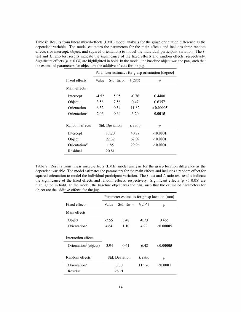
Table 6: Results from linear mixed-effects (LME) model analysis for the grasp orientation difference as thedependent variable. The model estimates the parameters for the main effects and includes three randomeffects (for intercept, object, and squared orientation) to model the individual participant variation. The t-test and L ratio test results indicate the significance of the fixed effects and random effects, respectively.Significant effects (p < 0.05) are highlighted in bold. In the model, the baseline object was the pan, such thatthe estimated parameters for object are the additive effects for the jug.
Parameter estimates for grasp orientation [degree]
Fixed effects Value Std. Error t(283) p
Main effects
Intercept -4.52 5.95 -0.76 0.4480Object 3.58 7.56 0.47 0.6357Orientation 6.32 0.54 11.82 <0.00005Orientation2 2.06 0.64 3.20 0.0015
Random effects Std. Deviation L ratio p
Intercept 17.20 40.77 <0.0001Object 22.32 62.09 <0.0001Orientation2 1.85 29.96 <0.0001Residual 20.81
Table 7: Results from linear mixed-effects (LME) model analysis for the grasp location difference as thedependent variable. The model estimates the parameters for the main effects and includes a random effect forsquared orientation to model the individual participant variation. The t-test and L ratio test results indicatethe significance of the fixed effects and random effects, respectively. Significant effects (p < 0.05) arehighlighted in bold. In the model, the baseline object was the pan, such that the estimated parameters forobject are the additive effects for the jug.
Parameter estimates for grasp location [mm]
Fixed effects Value Std. Error t(295) p
Main effects
Object -2.55 3.48 -0.73 0.465Orientation2 4.64 1.10 4.22 <0.00005
Interaction effects
Orientation2(object) -3.94 0.61 -6.48 <0.00005
Random effects Std. Deviation L ratio p
Orientation2 3.30 113.76 <0.0001Residual 28.91
14

symmetric, as indicated by the absence of any significant linear orientation effects in the LME model. Aswith the torque metric, the negative coefficient for the orientation2(object) interaction suggests that the trade-off of preparatory rotation is more pronounced for the pan than for the jug. For some participants, the grasplocation for lifting the pan in the object motion constraint phase changed dramatically. Instead of graspingclose to the handle end as they did in the unimanual constraint phase, they lifted the pan with a grasp closerto the center of the pan when the handle was further from reach. The use of preparatory rotation strategywhen it was permitted in the unimanual constraint phase might be due to the preference to grasp the objectnear the end of the handle, even though other grasps were feasible when object motion on the surface was notpermitted.
For each of the four dependent variables computed from the liftoff pose, the final LME model did not in-clude the effect of task repetition. The effect of task repetition was not statistically significant for significancelevel α = 0.05.
4.3 Perceptual ratingThe differences in perceptual response for comfort and naturalness between the unimanual constraint andobject motion constraint phases (Fig. 9) were also tested with LME models (Tables 8, 9). Neither object
5 6 7 8 1 2 3 4
−2
0
2
4
6
initial handle orientation
ratin
g di
ffere
nce
comfort for lifting jug
5 6 7 8 1 2 3 4
−2
0
2
4
6
initial handle orientation
ratin
g di
ffere
nce
comfort for lifting pan
a
5 6 7 8 1 2 3 4
−2
0
2
4
6
initial handle orientation
ratin
g di
ffere
nce
comfort for lifting object
jugpan
b
5 6 7 8 1 2 3 4
−2
0
2
4
6
initial handle orientation
ratin
g di
ffere
nce
naturalness for lifting jug
5 6 7 8 1 2 3 4
−2
0
2
4
6
initial handle orientation
ratin
g di
ffere
nce
naturalness for lifting pan
c
5 6 7 8 1 2 3 4
−2
0
2
4
6
initial handle orientation
ratin
g di
ffere
nce
naturalness for lifting object
jugpan
d
Figure 9: Difference in perceptual ratings over the 10 participants. The mean regression curve is determinedfrom the significant effects as tested by the linear mixed model. The differences are the ratings for unimanualconstraint tasks the rating for the object motion constraint task. (a) Comfort rating. (b) Naturalness rating.The positive mean values indicate that participants found the unimanual constraint lifting more comfortableand natural compared to lifting under the object motion constraint.
15

Table 8: Results from linear mixed-effects (LME) model analysis for the comfort rating difference as thedependent variable. The model estimates the parameters for the main effects and includes three randomeffects (for intercept, object, and squared orientation) to model the individual participant variation. The t-test and L ratio test results indicate the significance of the fixed effects and random effects, respectively.Significant effects (p < 0.05) are highlighted in bold. In the model, the baseline object was the pan, such thatthe estimated parameters for object are the additive effects for the jug.
Parameter estimates for grasp location [mm]
Fixed effects Value Std. Error t(307) p
Main effects
Intercept 0.88 0.29 3.06 0.0024Object 0.26 0.26 1.01 0.3132Orientation 0.15 0.02 7.95 <0.00005Orientation2 0.05 0.04 1.45 0.1472
Random effects Std. Deviation L ratio p
Intercept 0.87 75.88 <0.0001Object 0.77 50.15 <0.0001Orientation2 0.11 83.22 <0.0001Residual 0.78
Table 9: Results from linear mixed-effects (LME) model analysis for the naturalness rating difference asthe dependent variable. The model estimates the parameters for the main effects and includes three randomeffects (for intercept, object, and squared orientation) to model the individual participant variation. The t-test and L ratio test results indicate the significance of the fixed effects and random effects, respectively.Significant effects (p < 0.05) are highlighted in bold. In the model, the baseline object was the pan, such thatthe estimated parameters for object are the additive effects for the jug.
Parameter estimates for grasp location [mm]
Fixed effects Value Std. Error t(307) p
Main effects
Intercept 0.73 0.34 2.12 0.0351Object 0.16 0.42 0.39 0.6960Orientation 0.12 0.02 6.01 <0.00005Orientation2 0.09 0.05 1.72 0.0872
Random effects Std. Deviation L ratio p
Intercept 1.05 96.89 <0.0001Object 1.28 117.43 <0.0001Orientation2 0.16 157.96 <0.0001Residual 0.80
16
nor squared orientation was a significant fixed effect for either perceptual rating. The intercept, object, andsquared orientation were all significant random effects, indicating the high degree of individual variance. Thelack of a consistent trend among the participants may be due in part to the variation in self-reporting of theperceptual response.
Overall, the mean regression curves fitted from the LME model are similar for both the comfort andnaturalness ratings (Table 8). The differences of the unimanual constraint trials relative to the object motionconstraint trials were primarily non-negative. This illustrates that the performance of the lifting task trials wasmore comfortable and more natural when preparatory object adjustment was permitted compared to when itwas not permitted.
For both perceptual ratings, linear orientation was a significant factor such that the smallest differencesin perceived comfort and naturalness occurred around orientation 7. This may be due to the difference inthe rotation direction for starting initial handle orientations on the left side (orientations 1-4) and right side(orientations 5-8) of the central orientation (Fig. 5). Even though the object handle is rotated toward thecentral region, the unimanual constraint requires the dominant right hand to contact the object. When thehandle starts on the left side, participants tended to rotate the object by contacting the handle with an extendedwrist, while the wrist was flexed when rotating object handles from the right side. This quality of the objectrotation may have influenced the participants’ perception of the lifting task, even though the asymmetry wasnot reflected in the object rotation trend (Fig. 6).
17

5 DiscussionOverall, we have found that the preparatory rotation of heavy objects increases with the change in handleorientation away from the central preferred direction. When participants are instructed not to pre-rotate theobject prior to liftoff, they are still able to successfully complete the lifting and transport task. However, with-out adjusting the object orientation prior to lifting, participants performed the lifting task with different bodyposes with tilted torsos and extended elbow positions in order to reach the object handle. In a comparisonof the unimanual constraint trials to the object motion constraint, the differences in the joint torque metricand grasp configuration in the object frame computed from the body pose at liftoff follow a quadratic trend.This suggests that the preparatory object adjustment may be desirable because it allows the object lift to beperformed with lower joint torque load in the upper body and/or with a preferred grasp of the object handle.
Our experiments investigated the preparatory object adjustment in the specific context of right-handedlifting and lateral transport across the body. We focused on the effect of the initial object orientation on theselected body posture at object liftoff, but several other factors may affect the preparatory manipulation. Wewould expect similar adjustment strategies in other tasks with different constraints. For example, changing thelocation of the goal may result in a shift in the region of handle orientations at liftoff. Other task constraintsto consider include whether the object contact is performed with the right or left hand and timing restrictionsfor the completion of the task.
In particular, the difficulty of the task is expected to influence the degree of object adjustment. A smallnumber of participants performed additional lifting trials for an extra object. For a lightweight cookingspatula, there was limited object rotation observed across the different handle orientations. Perhaps theease of grasping the lightweight tool from its presented configuration did not warrant the cost of adjustmentbefore lifting. In another example, two participants performed the lifting tasks for a plastic can whose handlegeometry required specific placement of the thumb and fingers for a successful lift. The weight of the canwhen filled with water was similar to that of the filled jug and pan tested in the experiments. For this extraobject, we observed similar amounts of object rotation as was observed for the jug and the pan. A possiblefuture experiment might test the object rotation response to weight by changing the water level in the jugbetween different trials.
Our analysis focused on the difference in performance in terms of metrics computed from the single timeframe defined by the object liftoff. The body pose at liftoff was chosen as a representative snapshot of theperformance. It may be of interest to analyze performance metrics over the entire trial for a dynamic analysisof the motor task. In addition, an altered methodology designed for specifically measuring the time course ofthe different movement segments would allow for extended inquiry of the cognitive models for planning andevaluating alternative manipulation strategies.
The preparatory rotation strategy in response to lifting heavy object from different handle orientations isone example of how object configuration is adjusted in addition to the postural response. Preparatory rotationmay also be a strategy used for in-hand manipulation of tools, such as wielding a hammer or bringing a forkinto the grasp. For in-hand manipulation, the preparatory adjustment may depend highly on the final taskintent more so than the difficulty of lifting the tool. Future directions for research also include the studyof different preparatory manipulation strategies in context of other tasks. In addition to handle rotation,adjustment may include sliding, rolling, or tumbling maneuvers which re-configure the object to a moredesirable state.
18

6 AcknowledgmentsThis work was supported by the National Science Foundation (IIS-0326322, ECS-0325383, and CCF-0702443).L. Y. Chang is supported by a National Science Foundation Graduate Research Fellowship. The authors thankHoward Seltman for his guidance on the statistical analysis and Justin Macey for his assistance with the dataacquisition.
19
ReferencesBongers, R. M., Michaels, C. F., & Smitsman, A. W. (2004). Variations of tool and task characteristics reveal
that tool-use postures are anticipated. Journal of Motor Behavior, 36(3), 305–315.
Chang, C. C., Brown, D. R., Bloswick, D. S., & Hsiang, S. M. (2001). Biomechanical simulation of manuallifting using spacetime optimization. Journal of Biomechanics, 34(4), 527–532.
Chow, C. K., & Jacobson, D. H. (1971). Studies of human locomotion via optimal programming. Mathemat-ical Biosciences, 10(3-4), 239–306.
Clauser, C. E., McConville, J. T., & Young, J. (1969). Weight,volume and center of mass of segments of thehuman body. Tech. Rep. AMRL-TR-69-70, Aerospace Medical Research Laboratory, Wright-PattersonAir Force Base, Ohio., Antioch College, Yellow Springs, OH.
Desmurget, M., Prablanc, C., Arzi, M., Rossetti, Y., Paulignan, Y., & Urquizar, C. (1996). Integrated controlof hand transport and orientation during prehension movements. Experimental Brain Research, 110(2),265–278.
Dysart, M. J., & Woldstad, J. C. (1996). Posture prediction for static sagittal-plane lifting. Journal ofBiomechanics, 29(10), 1393–1397.
Engelbrecht, S. E. (1997). Minimum-torque posture control. PhD thesis, University of MassachusettsAmherst, Psychology. AAT 9721446.
Fischman, M. G. (1998). Constraints on grip-selection: minimizing awkwardness. Perceptual and MotorSkills, 86(1), 328–330.
Jeannerod, M. (1981). Attention and performance, chap. Intersegmental Coordination During Reaching atNatural Visual Objects, (pp. 153–169). Hillsdale, NJ: Lawrence Erlbaum Associates.
Johansson, R. (1996). Hand and brain: The neurophysiology and psychology of hand movements, chap.Sensory control of dexterous manipulation in humans, (pp. 381–414). New York: Academic Press.
Latash, M. L., Gelfand, I. M., Li, Z. M., & Zatsiorsky, V. M. (1998). Changes in the force-sharing patterninduced by modifications of visual feedback during force production by a set of fingers. ExperimentalBrain Research, 123(3), 255–262.
Li, Z. M., Latash, M. L., & Zatsiorsky, V. M. (1998). Force sharing among fingers as a model of the redun-dancy problem. Experimental Brain Research, 119(3), 276–286.
Pinheiro, J. C., & Bates, D. M. (2000). Mixed-effects models in S and S-PLUS. New York: Springer.
R Development Core Team (2008). R: A Language and Environment for Statistical Computing. R Foundationfor Statistical Computing, Vienna, Austria. http://www.R-project.org.
Rand, M. K., & Stelmach, G. E. (2005). Effect of orienting the finger opposition space in the control ofreach-to-grasp movements. Journal of Motor Behavior, 37(1), 65–78.
Rosenbaum, D. A., & Gaydos, M. J. (2008). A method for obtaining psychophysical estimates of movementcosts. Journal of Motor Behavior, 40(1), 11–17.
Rosenbaum, D. A., Marchak, F., Barnes, H. J., Vaughan, J., Slotta, J. D., & Jorgensen, M. J. (1990). At-tention and Performance XIII: Motor Representation and Control, chap. Constraints for Action Selection:Overhand Versus Underhand Grips, (pp. 321–342). Hillsdale, NJ: Lawrence Erlbaum Associates.
20

Rosenbaum, D. A., Vaughan, J., Barnes, H. J., & Jorgensen, M. J. (1992). Time course of movement planning:selection of handgrips for object manipulation. Journal of Experimental Psychology: Learning, Memory,and Cognition, 18(5), 1058–1073.
Rosenbaum, D. A., Vaughan, J., Jorgensen, M. J., Barnes, H. J., & Stewart, E. (1993). Attention and per-formance XIV - A silver jubilee: Synergies in experimental psychology, artificial intelligence and cogni-tive neuroscience, chap. Plans for object manipulation, (pp. 803–820). Cambridge: MIT Press, BradfordBooks.
Short, M. W., & Cauraugh, J. H. (1997). Planning macroscopic aspects of manual control: end-state comfortand point-of-change effects. Acta Psychologica, 96(1-2), 133–147.
Stelmach, G. E., Castiello, U., & Jeannerod, M. (1994). Orienting the finger opposition space during prehen-sion movements. Journal of Motor Behavior, 26(2), 178–186.
Turvey, M. T., Shockley, K., & Carello, C. (1999). Affordance, proper function, and the physical basis ofperceived heaviness. Cognition, 73(2), B17–B26.
Verbeke, G., & Molenberghs, G. (2000). Linear mixed models for longitudinal data. New York: Springer.
Zhang, W., & Rosenbaum, D. A. (2008). Planning for manual positioning: the end-state comfort effect formanual abduction-adduction. Experimental Brain Research, 184(3), 383–389.
21