Embed Size (px)
Citation preview

On-Orbit Assembly of Flexible Space Structures with SWARM
Jacob Katz, Swati Mohan, and David W. Miler
MIT Space Systems Laboratory
AIAA Infotech@Aerospace 2010
April 22, 2010
1
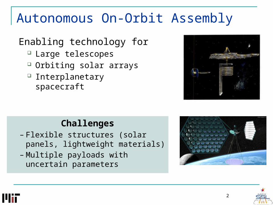
Autonomous On-Orbit Assembly
Enabling technology for Large telescopes Orbiting solar arrays Interplanetary spacecraft
Challenges– Flexible structures (solar panels,
lightweight materials)– Multiple payloads with uncertain
parameters
2
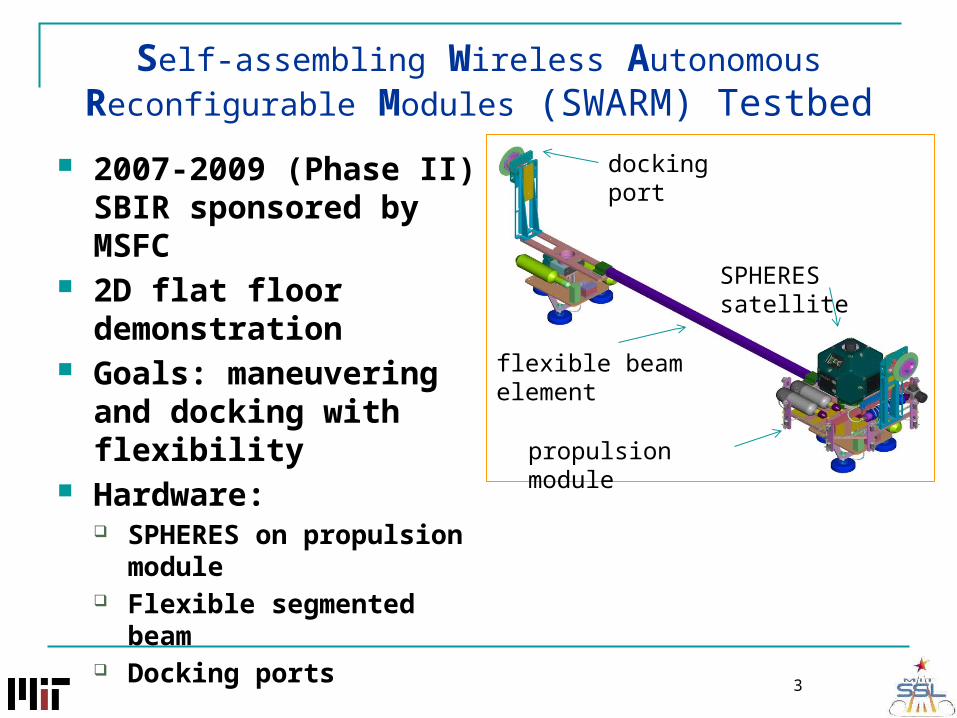
Self-assembling Wireless Autonomous Reconfigurable Modules (SWARM) Testbed
docking port 2007-2009 (Phase II) SBIR sponsored by MSFC
2D flat floor demonstration
Goals: maneuvering and docking with flexibility
Hardware: SPHERES on propulsion
module Flexible segmented beam Docking ports
propulsion module
flexible beam element
SPHERES satellite
3
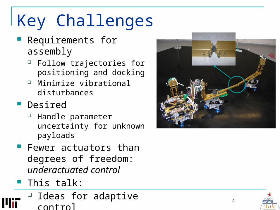
Key Challenges Requirements for assembly
Follow trajectories for positioning and docking
Minimize vibrational disturbances Desired
Handle parameter uncertainty for unknown payloads
Fewer actuators than degrees of freedom: underactuated control
This talk: Ideas for adaptive control Initial hardware testing
4
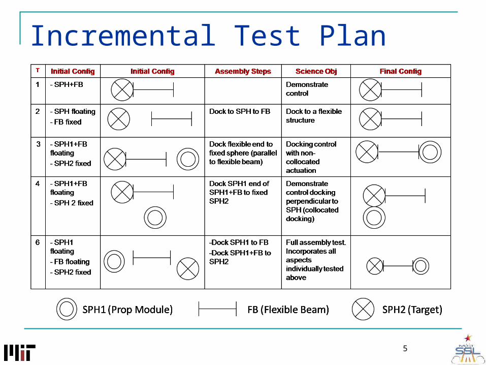
Incremental Test Plan
5

Test 1: Beam Control
6

SWARM as a Robot Manipulator
7
miδ1
δ2
δ3
0y
ki
x
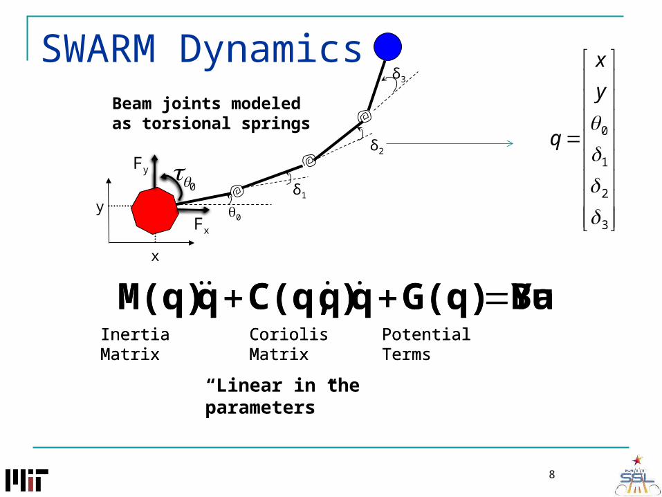
SWARM DynamicsBeam joints modeled as torsional springs
δ1
δ2
δ3
0y
Fy
Fx
x
3
2
1
0
y
x
q
8
Inertia Matrix Coriolis Matrix
BuG(q)q)qC(q,qM(q) Potential Terms
0
Inertia Matrix Coriolis Matrix
YaG(q)q)qC(q,qM(q) Potential Terms
“Linear in the parameters”

00
00
u
a
u
a
uuua
auaa
u
a
uuua
auaa
q
q
Kq
q
CC
CC
q
q
MM
MM
0
y
x
F
F
SWARM Dynamics
9
0
3
2
1
0
y
x
q
Beam joints modeled as torsional springs
δ1
δ2
δ3
0y
Fy
Fx
x
underactuated

Simplified Dynamic Model
Most important measurement for docking is tip deflection Reduces complexity of dynamic model for control and
estimation
10
δf
0y
x
k1
f
y
x
q
0
00
00
f
a
ff
a
fffa
afaa
u
a
fffa
afaa
q
q
Kq
q
CC
CC
q
q
MM
MM
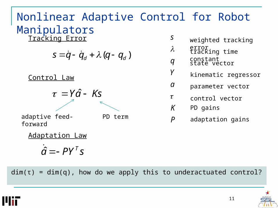
Nonlinear Adaptive Control for Robot Manipulators
11
sPYa T̂
P
K
a
Y
q
s
weighted tracking error
tracking time constant
kinematic regressor
parameter vector
control vector
state vector
PD gains
adaptation gains
)( dd qqqqs
adaptive feed-forward PD term
Tracking Error
Control Law
Adaptation Law
KsaY ˆ
dim(τ) = dim(q), how do we apply this to underactuated control?

Underactuated Adaptive Control
12
qJy
yy
qhy
sqa
fa
)(
Main idea: perform tracking in a lower dimensional task space y
)dim()(
)dim(
qJrank
p
y
sq
p
subject to
f
y
x
y
0
For example:
weighted combination of beam deflection and base rotation
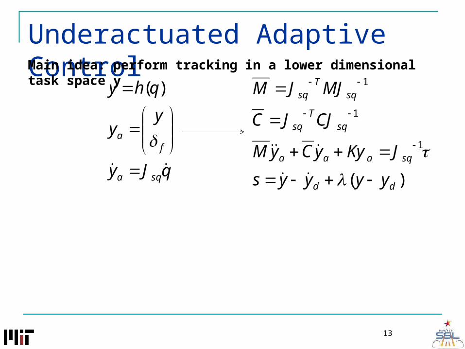
Underactuated Adaptive Control
13
qJy
yy
qhy
sqa
fa
)(
Main idea: perform tracking in a lower dimensional task space y
)(
1
1
1
dd
sqaaa
sqT
sq
sqT
sq
yyyys
JKyyCyM
CJJC
MJJM

Underactuated Adaptive Control
14
qJy
yy
qhy
sqa
fa
)(
Important to note inherent sacrifice in underactuated control Lose guarantee of tracking convergence for arbitrary state trajectories Best we can do is achieve tracking in the output space Need to show zero output error implies convergence of internal states
Main idea: perform tracking in a lower dimensional task space y
)(
1
1
1
dd
sqaaa
sqT
sq
sqT
sq
yyyys
JKyyCyM
CJJC
MJJM
0ˆ
01 KsaYJ sq
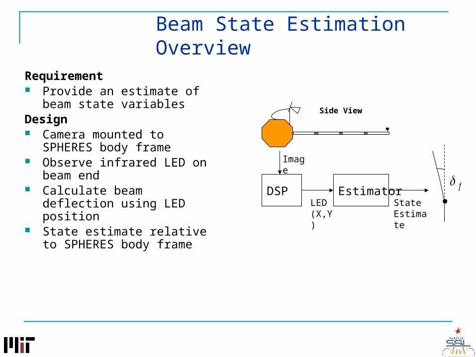
Beam State Estimation Overview
Requirement Provide an estimate of beam
state variablesDesign Camera mounted to SPHERES
body frame Observe infrared LED on beam
end Calculate beam deflection using
LED position State estimate relative to
SPHERES body frame
DSP
Image
EstimatorLED(X,Y)
State Estimate
f
Side View
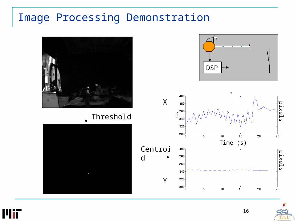
Image Processing Demonstration
Threshold
Centroid
X
Y
pixelspixels
Time (s)
EstimatorDSP
16

Beam Estimator
f
u
Z ≈ Beam Len
X
Image Plane
IR LEDSchematic View
Z
X
f
u
Perspective Projection
f
f
u
f
uf
1tan
Measure beam angle directly using perspective projection
Differentiate δf using LQE
DSP Estimator
ttft
ttftftf
vy
wt
1
17
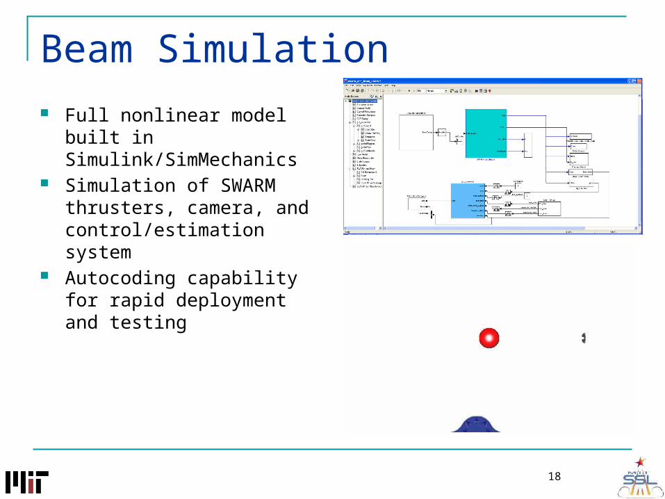
Beam Simulation Full nonlinear model built in
Simulink/SimMechanics Simulation of SWARM
thrusters, camera, and control/estimation system
Autocoding capability for rapid deployment and testing
18
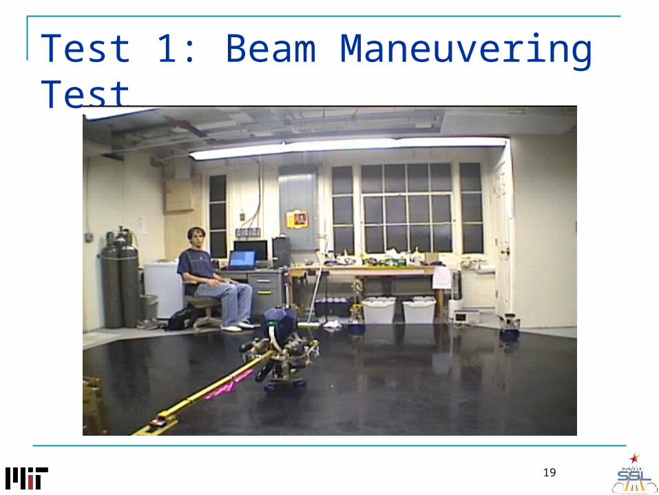
Test 1: Beam Maneuvering Test
19
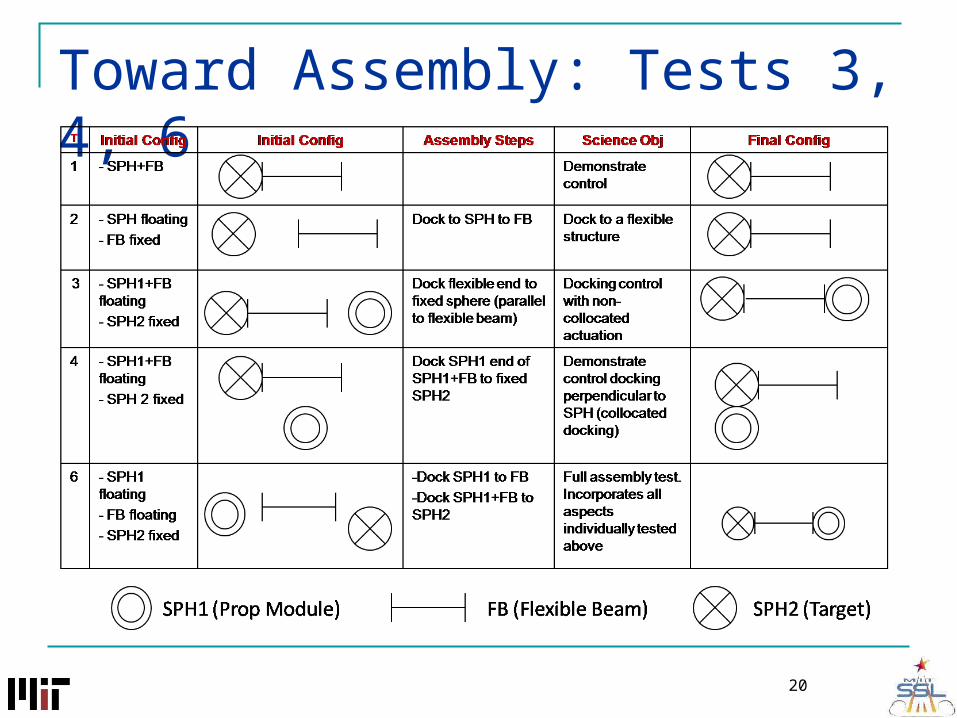
Toward Assembly: Tests 3, 4, 6
20
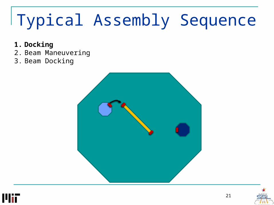
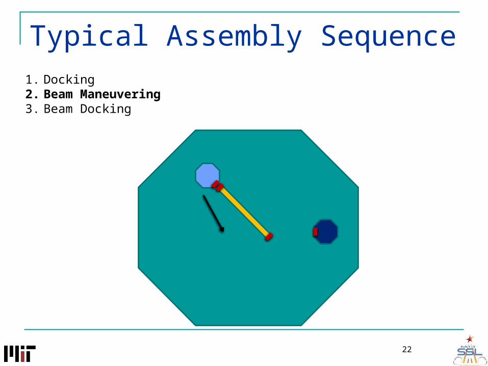
Typical Assembly Sequence1. Docking2. Beam Maneuvering3. Beam Docking
21
Typical Assembly Sequence1. Docking2. Beam Maneuvering3. Beam Docking
22

Typical Assembly Sequence1. Docking2. Beam Maneuvering3. Beam Docking
23
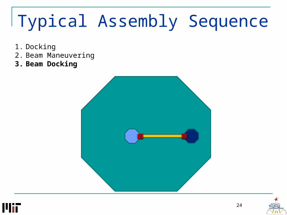
Typical Assembly Sequence1. Docking2. Beam Maneuvering3. Beam Docking
24
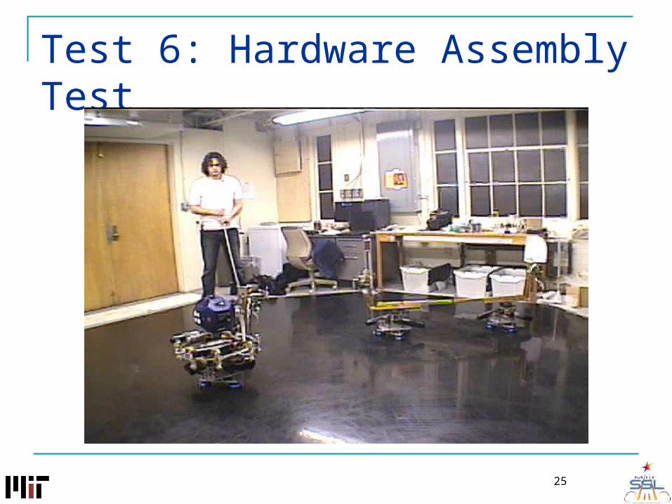
Test 6: Hardware Assembly Test
25
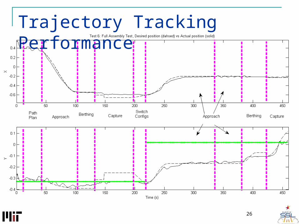
Trajectory Tracking Performance
26

Test 3: Beam Docking
27
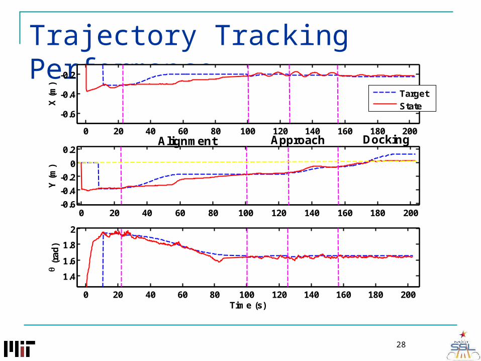
Trajectory Tracking Performance
28
0 20 40 60 80 100 120 140 160 180 200
-0.6
-0.4
-0.2
X (
m)
0 20 40 60 80 100 120 140 160 180 200-0.6
-0.4
-0.2
0
0.2
Y (
m)
0 20 40 60 80 100 120 140 160 180 200
1.4
1.6
1.8
2
Time (s)
(r
ad)
TargetState
Alignment Approach Docking
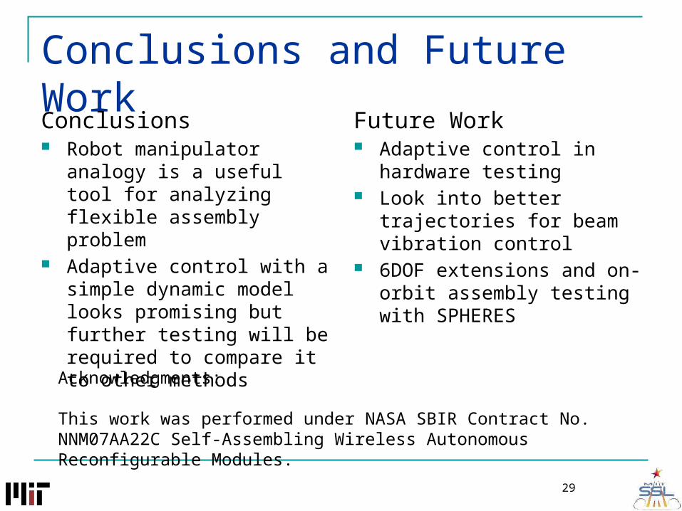
Conclusions and Future Work
Conclusions Robot manipulator analogy is a
useful tool for analyzing flexible assembly problem
Adaptive control with a simple dynamic model looks promising but further testing will be required to compare it to other methods
Future Work Adaptive control in hardware
testing Look into better trajectories for
beam vibration control 6DOF extensions and on-orbit
assembly testing with SPHERES
29
Acknowledgments:
This work was performed under NASA SBIR Contract No. NNM07AA22C Self-Assembling Wireless Autonomous Reconfigurable Modules.

Backup Slides
30

Perpendicular Docking
31
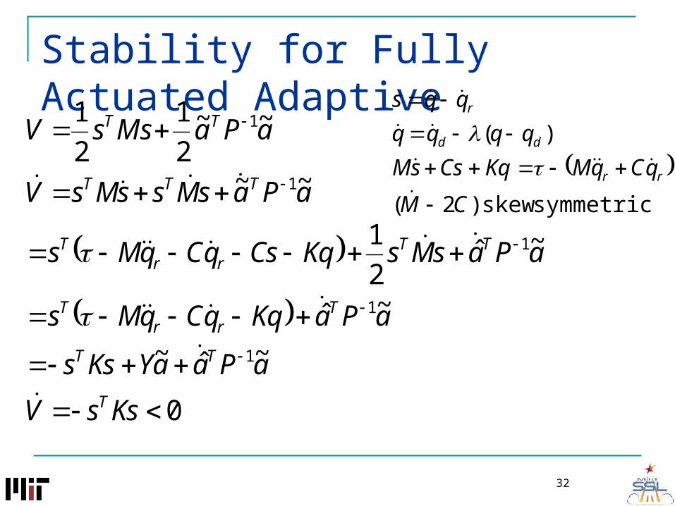
Stability for Fully Actuated Adaptive
32
0
~ˆ~
~ˆ
~ˆ2
1
~~
~~2
1
2
1
1
1
1
1
1
KssV
aPaaYKss
aPaKqqCqMs
aPasMsKqCsqCqMs
aPasMssMsV
aPaMssV
T
TT
Trr
T
TTrr
T
TTT
TT
symmetric skew)2(
)(
CM
qCqMKqCssM
qqqq
qqs
rr
dd
r

Flexible Structure Dynamics
33
Shahravi, 2005
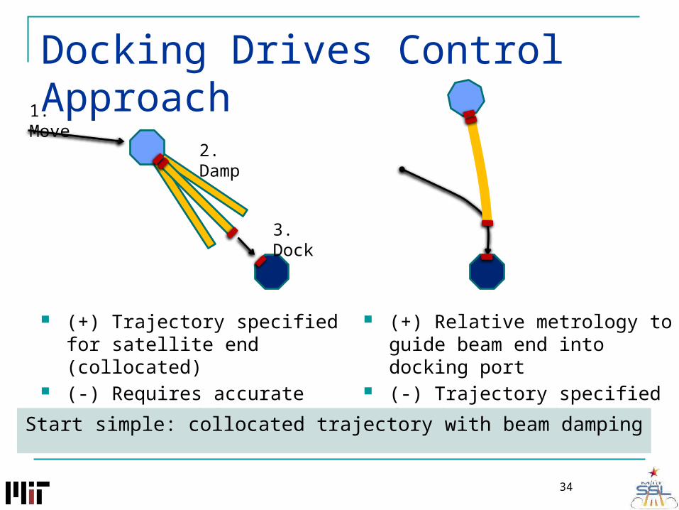
Docking Drives Control Approach1. Move
2. Damp
3. Dock
(+) Trajectory specified for satellite end (collocated)
(-) Requires accurate pointing and low vibration
(+) Relative metrology to guide beam end into docking port
(-) Trajectory specified for docking end (non-collocated)
34
Start simple: collocated trajectory with beam damping

Dynamics Derivation
Kinetic Energy: 3
0
1 1
2 2i i i i i ii
T m v v I
Potential Energy:3
2
0
1
2 i ii
U K
m1,I1
m2,I2
m3,I3
m4,I4
Q1
Q2
Q3
00
00
u
a
u
a
uuua
auaa
u
a
uuua
auaa
q
q
Kq
q
CC
CC
q
q
MM
MM
Inertia Matrix Coriolis Matrix
BuG(q)q)qC(q,qM(q) Potential Terms
35