Embed Size (px)
Citation preview
International Journal of Machine Tools & Manufacture 41 (2001) 1149–1163
On obtaining machine tool stiffness by CAE techniques
David Te-Yen Huang a,*, Jyh-Jon Lee b
a Department of Mechanical Engineering, Nan-Kai Institute of Technology, Nan-Tou, Taiwan 542, ROCb Department of Mechanical Engineering, National Taiwan University, Taipei, Taiwan 106, ROC
Received 7 July 2000; accepted 8 January 2001
Abstract
In this paper, a single module method and a newly developed hybrid modeling method for analyzingthe stiffness of machine tools are introduced in detail. Techniques include building suitable finite elementmodels, determining equivalent loads, simulating the interface between two modules, considering boundaryconstraints, and interpreting results. By taking a detailed finite element mesh for one of the five modules(the headstock, the column, the table, the saddle and the bed), together with simplified meshes for theother four modules, a hybrid finite element model is assembled. The elastic modulli of the four simplifiedmeshes are kept several orders higher than that of the detailed one. Therefore, the calculated stiffness ofthe hybrid model is essentially the stiffness of the softer module with the detailed mesh. The stiffness ofthe five modules can be obtained one after another in the same manner. By supporting the hybrid modelonly at the middle of the short edge on the bottom surface of the bed, the machine tool can be properlyconstrained, and its stiffness can be estimated correctly. The controversial issue as to how to simulateproperly the boundary condition of the casters under the bed will not occur in this method. A cumbersomeprocedure to transform the external loads into the equivalent forces as required in SMM is also avoided.There is no local effect due to unevenly distributed nodal forces. It is shown that the hybrid modelingmethod is better than the single module method in accuracy and efficiency. 2001 Elsevier Science Ltd.All rights reserved.
Keywords: Machine tool; Single module method; Hybrid modeling method; Stiffness analysis; Finite element method
1. Introduction
Many researchers have studied the stiffness of machine tools by experimental, analytical ornumerical methods in the past decades [1–9]. However, reports which include detailed technical
* Corresponding author.E-mail address: [email protected] (D.T.-Y. Huang).
0890-6955/01/$ - see front matter 2001 Elsevier Science Ltd. All rights reserved.PII: S0 890- 695 5(01 )000 12- 8
1150 D.T.-Y. Huang, J.-J. Lee / International Journal of Machine Tools & Manufacture 41 (2001) 1149–1163
know-how in analyzing the stiffness of machine tools by the applied numerical method, namely,the computer aided engineering (CAE) method, are difficult to find in literature.
This report is believed to pioneer the study of technical detail in the CAE method for analyzingthe stiffness of machine tools. It investigates two approaches: a Single Module Method (SMM)and a newly developed Hybrid Modeling Method (HMM). The techniques include building suit-able finite element models, determining nodal forces, transforming and applying equivalent loads,simulating the interface between two modules, considering boundary constraints, and inter-preting results.
The advantage of SMM lies in that only one module needs to be meshed, and hence less effortneeds to be put into preparing a finite element model. However, this method has some drawbacks.Firstly, it is necessary to transform the loads applied on the cutting tool, as well as those on thework-piece, into the equivalent forces. They are then applied onto the nodes within the interfacialareas between the two connecting modules. If the mesh is made using an auto-meshing process,densities of the nodes and shapes of the tetrahedral elements are difficult to control. Local defor-mation and over-stressing may happen at locations with higher nodal density. Secondly, usingSMM to analyze the stiffness, the boundary condition of each module is unique. Thus, the methodleads to a controversy as to whether boundary constraints can be properly simulated. Thirdly,there is no common base to compare the stiffness of different modules since their boundaryconstraints are different. Hence, it is not possible to know the influence of the stiffness of eachmodule on the entire strength of the machine tool.
HMM is processed by taking a detailed finite element mesh for one of the five modules (theheadstock, the column, the table, the saddle and the bed), together with simplified meshes for theother four modules, to assemble a hybrid model of the machine tool. By supporting the hybridmodel only at the middle of the short edge on the bottom surface of the bed, the machine toolcan be properly constrained, and its stiffness can be estimated correctly. The controversial issueon the constraint condition of the casters under the bed will not occur in this method. UsingHMM, external loading only needs to be applied on the cutting tool and the work-piece. A cumber-some procedure to transform the external loads into the equivalent forces as required in SMM isavoided. There is no local effect due to unevenly distributed nodal forces. Since each hybridmodel is constrained at the same point, the stiffness of each module is comparable. The weakermodules in the machine tool can be identified and modified.
The report is organized as follows: In Section 2, a machine tool for analysis is described. InSection 3, the SMM for stiffness analysis is reviewed and illustrated with two examples. In Section4, the HMM is introduced. In Section 5, results of both methods are presented and compared.Conclusions are given in Section 6.
2. The machine tool structure and the coordinate system
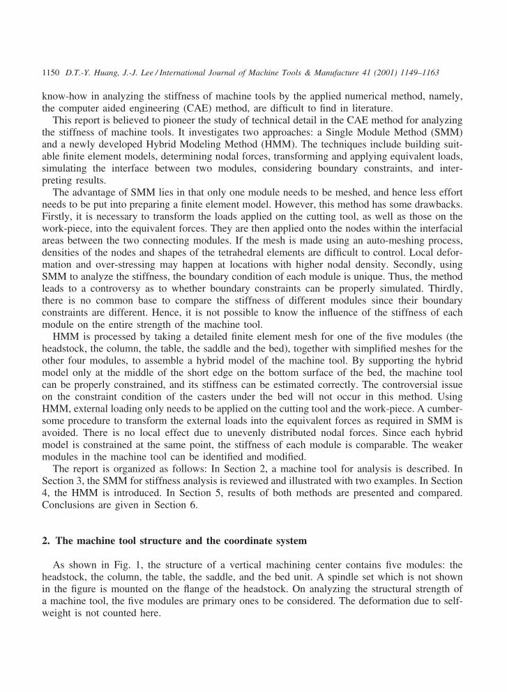
As shown in Fig. 1, the structure of a vertical machining center contains five modules: theheadstock, the column, the table, the saddle, and the bed unit. A spindle set which is not shownin the figure is mounted on the flange of the headstock. On analyzing the structural strength ofa machine tool, the five modules are primary ones to be considered. The deformation due to self-weight is not counted here.
1151D.T.-Y. Huang, J.-J. Lee / International Journal of Machine Tools & Manufacture 41 (2001) 1149–1163
Fig. 1. The five major modules and the coordinate system of a vertical machining center.
The coordinate system is defined by the right hand rule. As shown in Fig. 1, the +X-axis isdefined pointing from the left to the right, the +Z-axis from the bottom to the top, and the +Y-axisfrom the foreground to the background. Throughout the paper, this sign convention is followed toposition boundary constraints, to direct forces and displacements, and to define stiffness.
3. Stiffness analysis by the single module method (SMM)
Due to the complexity of each module, its finite element mesh is built using the auto-meshingprocess to save modeling time. Unit forces applied at the tool tip and the work-piece are transfor-med into equivalent forces acting on each single module. Coupling components which connecttwo modules, such as the linear guide blocks or the bolted joints, are considered as constraintsin SMM, which is illustrated by the following two examples.
3.1. Stiffness analysis of the column
The finite element model of the column is established using the auto-mesh process with twotypes of elements. The regularly shaped reinforcing ribs and walls of the column are modeled byshell elements, and the irregularly shaped outer structure is modeled by tetrahedral elements.There are two boundaries where the column interfaces with other modules: one at the bottomsurface (jointed to the bed by several bolts) and the other at the front surface (connected to theheadstock by four linear guide blocks). At the bottom surface, the nodes located at the positionsof the holes for bolting are fully constrained to simulate the fixed boundary conditions. Loadingis transmitted from the headstock to the column through the four linear guide blocks, shown asrectangular areas with numbers in Fig. 2. On analyzing the stiffness of the column, it is necessaryto transform external forces originally applied on the tool tip into equivalent forces and then applythem onto the four block areas. How the equivalent forces are obtained is described below byvector analysis:
1152 D.T.-Y. Huang, J.-J. Lee / International Journal of Machine Tools & Manufacture 41 (2001) 1149–1163
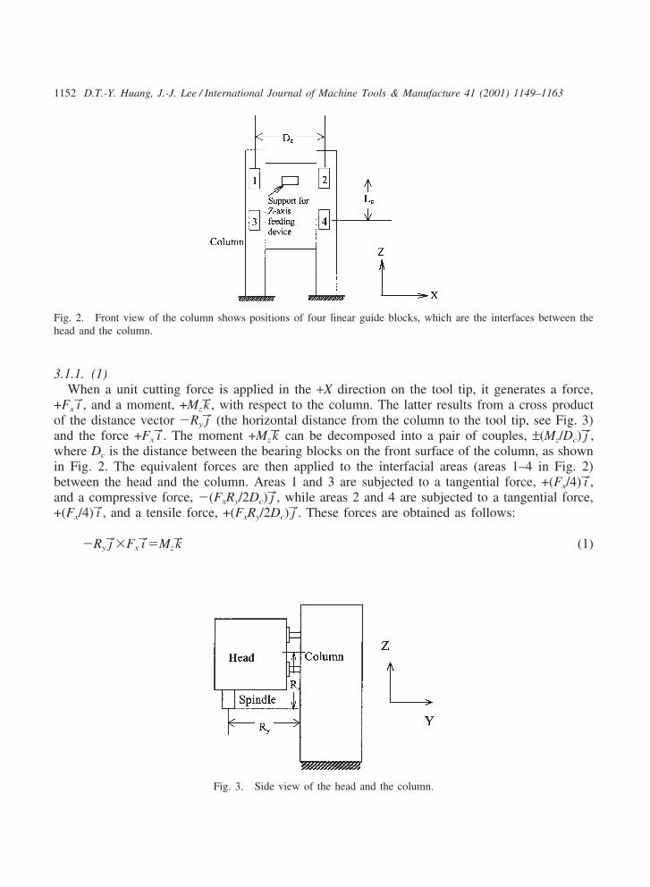
Fig. 2. Front view of the column shows positions of four linear guide blocks, which are the interfaces between thehead and the column.
3.1.1. (1)When a unit cutting force is applied in the +X direction on the tool tip, it generates a force,
+Fx i→, and a moment, +Mzk→, with respect to the column. The latter results from a cross productof the distance vector �Ry j→ (the horizontal distance from the column to the tool tip, see Fig. 3)and the force +Fx i→. The moment +Mz k→ can be decomposed into a pair of couples, ±(Mz/Dc) j→,where Dc is the distance between the bearing blocks on the front surface of the column, as shownin Fig. 2. The equivalent forces are then applied to the interfacial areas (areas 1–4 in Fig. 2)between the head and the column. Areas 1 and 3 are subjected to a tangential force, +(Fx/4) i→,and a compressive force, �(FxRy/2Dc) j→, while areas 2 and 4 are subjected to a tangential force,+(Fx/4) i→, and a tensile force, +(FxRy/2Dc) j→. These forces are obtained as follows:
�Ry j→�Fx i→�Mz k→ (1)
Fig. 3. Side view of the head and the column.
1153D.T.-Y. Huang, J.-J. Lee / International Journal of Machine Tools & Manufacture 41 (2001) 1149–1163
Dc i→�(Mz/Dc) j→�Mzk→ (2)
Substituting the magnitude of Mz from Eq. (1) into Eq. (2) obtains the magnitude of the couplein terms of the force Fx and the distance Ry as:
Dc i→�(Mz/Dc) j→�[Dc i→�2(FxRy/2Dc) j→] (3)
3.1.2. (2)When a unit cutting force is applied in the +Y direction on the tool tip, it generates a force,
+Fy j→, and a moment, +Mx i→, with respect to the column. The latter results from a cross productof the distance vector �Rzk→ (the vertical distance from the center of the upper and the lowerbearing blocks to the tool tip, see Fig. 3) and the unit force +Fy j→. The moment +Mx i→ can bedecomposed into a pair of couples, ±(Mx/Lc) j→, where Lc is the distance between the centerlinesof the upper and the lower bearing blocks, as shown in Fig. 2. The equivalent forces are appliedto the interfacial areas (areas 1–4 in Fig. 2) between the head and the column. Areas 1 and 2 aresubjected to a tensile force, +(Fy/4) j→, and a compressive force, �(FyRz/2Lc) j→; while areas 3 and4 are subjected to two tensile forces, +(Fy/4) j→ and +(FyRz/2Lc) j→. These forces are obtained as fol-lows:
�Rzk→�Fy j→�Mx i→ (4)
�Lck→�(Mx/Lc) j→�Mx i→ (5)
Substituting the magnitude of Mx from Eq. (4) into Eq. (5) obtains the magnitude of the couplein terms of the force Fy and the distance Rz as:
�Lck→�(Mx/Lc) j→��[Lck→�2(FyRz/2Lc) j→] (6)
3.1.3. (3)When a unit force is applied in the +Z direction on the tool tip, a force, +Fzk→, is generated on
the lower surface of the support of the Z-axis feeding device, and a moment, �Mx i→, on thebearing block areas (areas 1–4, see Fig. 2). The latter results from a cross product of the distancevector �Ry j→ and the unit force +Fzk→. The moment �Mx i→ can be decomposed into a pair ofcouples, ±(Mx/Lc) j→. Areas 1 and 2 are subjected to a tensile force, +(FzRy/2Lc) j→, while areas 3and 4 are subjected to a compressive force, �(FzRy/2Lc) j→.
After the displacements of the loaded structure are calculated, the stiffness of the column aroundthe interfacial areas can be obtained by taking the inverse of the averaged nodal displacementswithin the four block areas.
1154 D.T.-Y. Huang, J.-J. Lee / International Journal of Machine Tools & Manufacture 41 (2001) 1149–1163
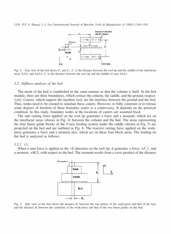
Fig. 4. Top view of the bed shows Cx and Cy. Cx is the distance between the tool tip and the middle of the interfacialareas A2A1 and A4A3; Cy is the distance between the tool tip and the middle of area A2A1.
3.2. Stiffness analysis of the bed
The mesh of the bed is established in the same manner as that the column is built. In the bedmodule, there are three boundaries, which contact the column, the saddle, and the ground, respect-ively. Casters, which support the machine tool, are the interface between the ground and the bed.Thus, nodes need to be created to simulate these casters. However, to fully constrain or to releasesome degrees of freedom of these boundary nodes is a controversy. It depends on the practicalcondition. In this study, boundary nodes at the locations of casters are assumed fixed.
The unit cutting force applied on the tool tip generates a force and a moment, which act onthe interfacial areas (shown in Fig. 4) between the column and the bed. The areas representingthe four linear guide blocks of the Y-axis feeding system under the saddle (shown in Fig. 5) areprojected on the bed and are outlined in Fig. 6. The reactive cutting force applied on the work-piece generates a force and a moment also, which act on these four block areas. The loading onthe bed is analyzed as follows:
3.2.1. (1)When a unit force is applied in the +X direction on the tool tip, it generates a force, +Fx i→, and
a moment, +Mzk→, with respect to the bed. The moment results from a cross product of the distance
Fig. 5. Side view of the bed shows the distance Bz between the top surface of the work-piece and that of the bed,and the distance Bx between the centerline of the work-piece and that of the two linear guides on the bed.
1155D.T.-Y. Huang, J.-J. Lee / International Journal of Machine Tools & Manufacture 41 (2001) 1149–1163
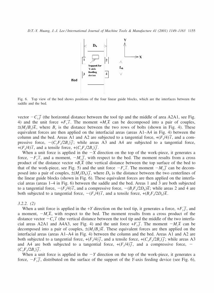
Fig. 6. Top view of the bed shows positions of the four linear guide blocks, which are the interfaces between thesaddle and the bed.
vector �Cy j→ (the horizontal distance between the tool tip and the middle of area A2A1, see Fig.4) and the unit force +Fx i→. The moment +Mz k→ can be decomposed into a pair of couples,±(Mz/Bs)k→, where Bs is the distance between the two rows of bolts (shown in Fig. 4). Theseequivalent forces are then applied on the interfacial areas (areas A1–A4 in Fig. 4) between thecolumn and the bed. Areas A1 and A2 are subjected to a tangential force, +(Fx/4) i→, and a com-pressive force, �(CyFx/2Bs) j→; while areas A3 and A4 are subjected to a tangential force,+(Fx/4) i→, and a tensile force, +(CyFx/2Bs) j→.
When a unit force is applied in the �X direction on the top of the work-piece, it generates aforce, �Fx i→, and a moment, �My j→, with respect to the bed. The moment results from a crossproduct of the distance vector +Bz k→ (the vertical distance between the top surface of the bed tothat of the work-piece, see Fig. 5) and the unit force �Fx i→. The moment �My j→ can be decom-posed into a pair of couples, ±(My/Db) j→, where Db is the distance between the two centerlines ofthe linear guide blocks (shown in Fig. 6). These equivalent forces are then applied on the interfa-cial areas (areas 1–4 in Fig. 6) between the saddle and the bed. Areas 1 and 3 are both subjectedto a tangential force, �(Fx/4) i→, and a compressive force, �(BzFx/2Db)k→; while areas 2 and 4 areboth subjected to a tangential force, �(Fx/4) i→, and a tensile force, +(BzFx/2Db)k→.
3.2.2. (2)When a unit force is applied in the +Y direction on the tool tip, it generates a force, +Fy j→, and
a moment, �Mz k→, with respect to the bed. The moment results from a cross product of thedistance vector �Cx i→ (the vertical distance between the tool tip and the middle of the two interfa-cial areas A2A1 and A4A3, see Fig. 4) and the unit force +Fy j→. The moment �Mzk→ can bedecomposed into a pair of couples, ±(Mz/Bs)k→. These equivalent forces are then applied on theinterfacial areas (areas A1–A4 in Fig. 4) between the column and the bed. Areas A1 and A2 areboth subjected to a tangential force, +(Fy/4) j→, and a tensile force, +(CxFy/2Bs) j→; while areas A3and A4 are both subjected to a tangential force, +(Fy/4) j→, and a compressive force, �(CxFy/2Bs) j→.
When a unit force is applied in the �Y direction on the top of the work-piece, it generates aforce, �Fy j→, distributed on the surface of the support of the Y-axis feeding device (see Fig. 6),
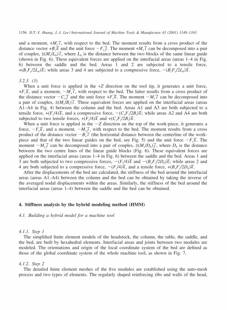
1156 D.T.-Y. Huang, J.-J. Lee / International Journal of Machine Tools & Manufacture 41 (2001) 1149–1163
and a moment, +Mx i→, with respect to the bed. The moment results from a cross product of thedistance vector +Bz k→ and the unit force �Fy j→. The moment +Mx i→ can be decomposed into a pairof couples, ±(Mx/Lb) i→, where Lb is the distance between the two blocks of the same linear guide(shown in Fig. 6). These equivalent forces are applied on the interfacial areas (areas 1–4 in Fig.6) between the saddle and the bed. Areas 1 and 2 are subjected to a tensile force,+(BzFy/2Lb)k→; while areas 3 and 4 are subjected to a compressive force, �(BzFy/2Lb)k→.
3.2.3. (3)When a unit force is applied in the +Z direction on the tool tip, it generates a unit force,
+Fz k→, and a moment, �Mx i→, with respect to the bed. The latter results from a cross product ofthe distance vector �Cy j→ and the unit force +Fz k→. The moment �Mx i→ can be decomposed intoa pair of couples, ±(Mx/Bt) i→. These equivalent forces are applied on the interfacial areas (areasA1–A4 in Fig. 4) between the column and the bed. Areas A1 and A3 are both subjected to atensile force, +(Fz/4)k→, and a compressive force, �(CyFz/2Bt)k→; while areas A2 and A4 are bothsubjected to two tensile forces, +(Fz/4)k→ and +(CyFz/2Bt)k→.
When a unit force is applied in the �Z direction on the top of the work-piece, it generates aforce, �Fzk→, and a moment, �My j→, with respect to the bed. The moment results from a crossproduct of the distance vector �Bx i→ (the horizontal distance between the centerline of the work-piece and that of the two linear guides on the bed, see Fig. 5) and the unit force �Fzk→. Themoment �My j→ can be decomposed into a pair of couples, ±(My/Db) j→, where Db is the distancebetween the two centre lines of the linear guide blocks (Fig. 6). These equivalent forces areapplied on the interfacial areas (areas 1–4 in Fig. 6) between the saddle and the bed. Areas 1 and3 are both subjected to two compressive forces, �(Fz/4)k→ and �(BxFz/2Db)k→; while areas 2 and4 are both subjected to a compressive force, �(Fz/4)k→, and a tensile force, +(BxFz/2Db)k→.
After the displacements of the bed are calculated, the stiffness of the bed around the interfacialareas (areas A1–A4) between the column and the bed can be obtained by taking the inverse ofthe averaged nodal displacements within the areas. Similarly, the stiffness of the bed around theinterfacial areas (areas 1–4) between the saddle and the bed can be obtained.
4. Stiffness analysis by the hybrid modeling method (HMM)
4.1. Building a hybrid model for a machine tool
4.1.1. Step 1The simplified finite element models of the headstock, the column, the table, the saddle, and
the bed, are built by hexahedral elements. Interfacial areas and joints between two modules aremodeled. The orientations and origin of the local coordinate system of the bed are defined asthose of the global coordinate system of the whole machine tool, as shown in Fig. 7.
4.1.2. Step 2The detailed finite element meshes of the five modules are established using the auto-mesh
process and two types of elements. The regularly shaped reinforcing ribs and walls of the head,
1157D.T.-Y. Huang, J.-J. Lee / International Journal of Machine Tools & Manufacture 41 (2001) 1149–1163
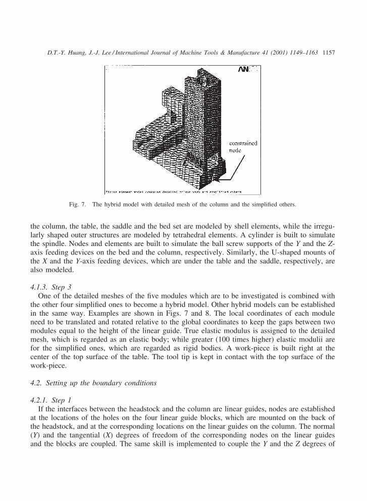
Fig. 7. The hybrid model with detailed mesh of the column and the simplified others.
the column, the table, the saddle and the bed set are modeled by shell elements, while the irregu-larly shaped outer structures are modeled by tetrahedral elements. A cylinder is built to simulatethe spindle. Nodes and elements are built to simulate the ball screw supports of the Y and the Z-axis feeding devices on the bed and the column, respectively. Similarly, the U-shaped mounts ofthe X and the Y-axis feeding devices, which are under the table and the saddle, respectively, arealso modeled.
4.1.3. Step 3One of the detailed meshes of the five modules which are to be investigated is combined with
the other four simplified ones to become a hybrid model. Other hybrid models can be establishedin the same way. Examples are shown in Figs. 7 and 8. The local coordinates of each moduleneed to be translated and rotated relative to the global coordinates to keep the gaps between twomodules equal to the height of the linear guide. True elastic modulus is assigned to the detailedmesh, which is regarded as an elastic body; while greater (100 times higher) elastic modulii arefor the simplified ones, which are regarded as rigid bodies. A work-piece is built right at thecenter of the top surface of the table. The tool tip is kept in contact with the top surface of thework-piece.
4.2. Setting up the boundary conditions
4.2.1. Step 1If the interfaces between the headstock and the column are linear guides, nodes are established
at the locations of the holes on the four linear guide blocks, which are mounted on the back ofthe headstock, and at the corresponding locations on the linear guides on the column. The normal(Y) and the tangential (X) degrees of freedom of the corresponding nodes on the linear guidesand the blocks are coupled. The same skill is implemented to couple the Y and the Z degrees of
1158 D.T.-Y. Huang, J.-J. Lee / International Journal of Machine Tools & Manufacture 41 (2001) 1149–1163
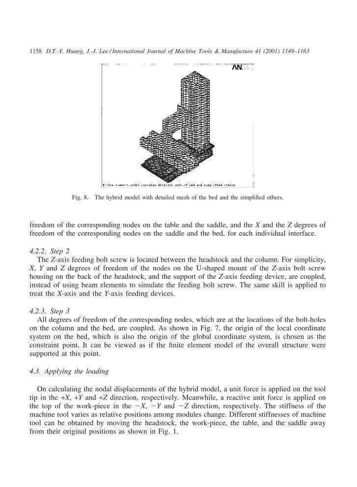
Fig. 8. The hybrid model with detailed mesh of the bed and the simplified others.
freedom of the corresponding nodes on the table and the saddle, and the X and the Z degrees offreedom of the corresponding nodes on the saddle and the bed, for each individual interface.
4.2.2. Step 2The Z-axis feeding bolt screw is located between the headstock and the column. For simplicity,
X, Y and Z degrees of freedom of the nodes on the U-shaped mount of the Z-axis bolt screwhousing on the back of the headstock, and the support of the Z-axis feeding device, are coupled,instead of using beam elements to simulate the feeding bolt screw. The same skill is applied totreat the X-axis and the Y-axis feeding devices.
4.2.3. Step 3All degrees of freedom of the corresponding nodes, which are at the locations of the bolt-holes
on the column and the bed, are coupled. As shown in Fig. 7, the origin of the local coordinatesystem on the bed, which is also the origin of the global coordinate system, is chosen as theconstraint point. It can be viewed as if the finite element model of the overall structure weresupported at this point.
4.3. Applying the loading
On calculating the nodal displacements of the hybrid model, a unit force is applied on the tooltip in the +X, +Y and +Z direction, respectively. Meanwhile, a reactive unit force is applied onthe top of the work-piece in the �X, �Y and �Z direction, respectively. The stiffness of themachine tool varies as relative positions among modules change. Different stiffnesses of machinetool can be obtained by moving the headstock, the work-piece, the table, and the saddle awayfrom their original positions as shown in Fig. 1.
1159D.T.-Y. Huang, J.-J. Lee / International Journal of Machine Tools & Manufacture 41 (2001) 1149–1163
4.4. Interpreting the results
The relative stiffnesses, Kx, Ky and Kz (in kgf/µm) are defined as reciprocals of the nodaldisplacements of each module. Based on the relative displacements between the tool tip and thecutting point on the top of the work-piece, the contribution of each module to the stiffness of anentire machine can be estimated. Since the elastic moduli of the simplified modules are kept twoorders higher than that of the detailed one, the calculated stiffness of the hybrid model is essen-tially the stiffness of the softer module with detailed mesh. The stiffness of all five modules canbe obtained in the same manner.
5. Numerical results and discussion
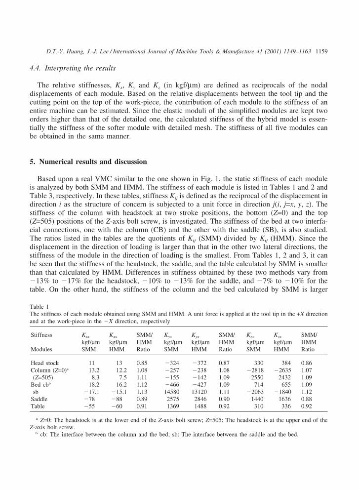
Based upon a real VMC similar to the one shown in Fig. 1, the static stiffness of each moduleis analyzed by both SMM and HMM. The stiffness of each module is listed in Tables 1 and 2 andTable 3, respectively. In these tables, stiffness Kij is defined as the reciprocal of the displacement indirection i as the structure of concern is subjected to a unit force in direction j(i, j=x, y, z). Thestiffness of the column with headstock at two stroke positions, the bottom (Z=0) and the top(Z=505) positions of the Z-axis bolt screw, is investigated. The stiffness of the bed at two interfa-cial connections, one with the column (CB) and the other with the saddle (SB), is also studied.The ratios listed in the tables are the quotients of Kij (SMM) divided by Kij (HMM). Since thedisplacement in the direction of loading is larger than that in the other two lateral directions, thestiffness of the module in the direction of loading is the smallest. From Tables 1, 2 and 3, it canbe seen that the stiffness of the headstock, the saddle, and the table calculated by SMM is smallerthan that calculated by HMM. Differences in stiffness obtained by these two methods vary from�13% to �17% for the headstock, �10% to �13% for the saddle, and �7% to �10% for thetable. On the other hand, the stiffness of the column and the bed calculated by SMM is larger
Table 1The stiffness of each module obtained using SMM and HMM. A unit force is applied at the tool tip in the +X directionand at the work-piece in the �X direction, respectively
Stiffness Kxx Kxx SMM/ Kyx Kyx SMM/ Kzx Kzx SMM/kgf/µm kgf/µm HMM kgf/µm kgf/µm HMM kgf/µm kgf/µm HMM
Modules SMM HMM Ratio SMM HMM Ratio SMM HMM Ratio
Head stock 11 13 0.85 �324 �372 0.87 330 384 0.86Column (Z=0)a 13.2 12.2 1.08 �257 �238 1.08 �2818 �2635 1.07(Z=505) 8.3 7.5 1.11 �155 �142 1.09 2550 2432 1.09
Bed cbb 18.2 16.2 1.12 �466 �427 1.09 714 655 1.09sb �17.1 �15.1 1.13 14580 13120 1.11 �2063 �1840 1.12
Saddle �78 �88 0.89 2575 2846 0.90 1440 1636 0.88Table �55 �60 0.91 1369 1488 0.92 310 336 0.92
a Z=0: The headstock is at the lower end of the Z-axis bolt screw; Z=505: The headstock is at the upper end of theZ-axis bolt screw.
b cb: The interface between the column and the bed; sb: The interface between the saddle and the bed.
1160 D.T.-Y. Huang, J.-J. Lee / International Journal of Machine Tools & Manufacture 41 (2001) 1149–1163
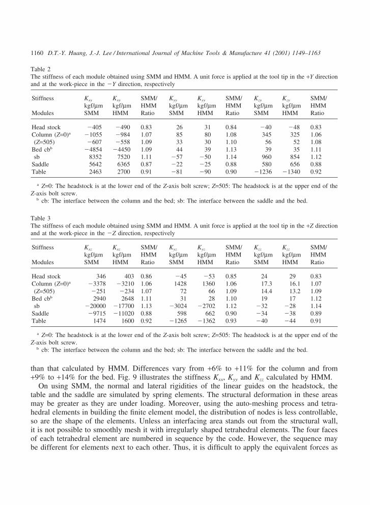
Table 2The stiffness of each module obtained using SMM and HMM. A unit force is applied at the tool tip in the +Y directionand at the work-piece in the �Y direction, respectively
Stiffness Kxy Kxy SMM/ Kyy Kyy SMM/ Kzy Kzy SMM/kgf/µm kgf/µm HMM kgf/µm kgf/µm HMM kgf/µm kgf/µm HMM
Modules SMM HMM Ratio SMM HMM Ratio SMM HMM Ratio
Head stock �405 �490 0.83 26 31 0.84 �40 �48 0.83Column (Z=0)a �1055 �984 1.07 85 80 1.08 345 325 1.06(Z=505) �607 �558 1.09 33 30 1.10 56 52 1.08
Bed cbb �4854 �4450 1.09 44 39 1.13 39 35 1.11sb 8352 7520 1.11 �57 �50 1.14 960 854 1.12
Saddle 5642 6365 0.87 �22 �25 0.88 580 656 0.88Table 2463 2700 0.91 �81 �90 0.90 �1236 �1340 0.92
a Z=0: The headstock is at the lower end of the Z-axis bolt screw; Z=505: The headstock is at the upper end of theZ-axis bolt screw.
b cb: The interface between the column and the bed; sb: The interface between the saddle and the bed.
Table 3The stiffness of each module obtained using SMM and HMM. A unit force is applied at the tool tip in the +Z directionand at the work-piece in the �Z direction, respectively
Stiffness Kxz Kxz SMM/ Kyz Kyz SMM/ Kzz Kzz SMM/kgf/µm kgf/µm HMM kgf/µm kgf/µm HMM kgf/µm kgf/µm HMM
Modules SMM HMM Ratio SMM HMM Ratio SMM HMM Ratio
Head stock 346 403 0.86 �45 �53 0.85 24 29 0.83Column (Z=0)a �3378 �3210 1.06 1428 1360 1.06 17.3 16.1 1.07(Z=505) �251 �234 1.07 72 66 1.09 14.4 13.2 1.09
Bed cbb 2940 2648 1.11 31 28 1.10 19 17 1.12sb �20000 �17700 1.13 �3024 �2702 1.12 �32 �28 1.14
Saddle �9715 �11020 0.88 598 662 0.90 �34 �38 0.89Table 1474 1600 0.92 �1265 �1362 0.93 �40 �44 0.91
a Z=0: The headstock is at the lower end of the Z-axis bolt screw; Z=505: The headstock is at the upper end of theZ-axis bolt screw.
b cb: The interface between the column and the bed; sb: The interface between the saddle and the bed.
than that calculated by HMM. Differences vary from +6% to +11% for the column and from+9% to +14% for the bed. Fig. 9 illustrates the stiffness Kxx, Kyy and Kzz calculated by HMM.
On using SMM, the normal and lateral rigidities of the linear guides on the headstock, thetable and the saddle are simulated by spring elements. The structural deformation in these areasmay be greater as they are under loading. Moreover, using the auto-meshing process and tetra-hedral elements in building the finite element model, the distribution of nodes is less controllable,so are the shape of the elements. Unless an interfacing area stands out from the structural wall,it is not possible to smoothly mesh it with irregularly shaped tetrahedral elements. The four facesof each tetrahedral element are numbered in sequence by the code. However, the sequence maybe different for elements next to each other. Thus, it is difficult to apply the equivalent forces as
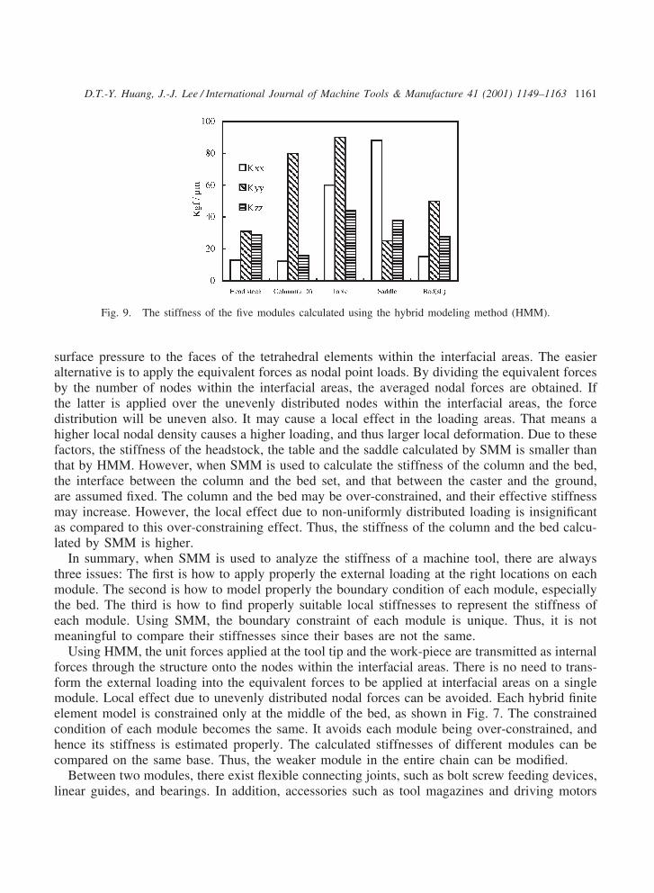
1161D.T.-Y. Huang, J.-J. Lee / International Journal of Machine Tools & Manufacture 41 (2001) 1149–1163
Fig. 9. The stiffness of the five modules calculated using the hybrid modeling method (HMM).
surface pressure to the faces of the tetrahedral elements within the interfacial areas. The easieralternative is to apply the equivalent forces as nodal point loads. By dividing the equivalent forcesby the number of nodes within the interfacial areas, the averaged nodal forces are obtained. Ifthe latter is applied over the unevenly distributed nodes within the interfacial areas, the forcedistribution will be uneven also. It may cause a local effect in the loading areas. That means ahigher local nodal density causes a higher loading, and thus larger local deformation. Due to thesefactors, the stiffness of the headstock, the table and the saddle calculated by SMM is smaller thanthat by HMM. However, when SMM is used to calculate the stiffness of the column and the bed,the interface between the column and the bed set, and that between the caster and the ground,are assumed fixed. The column and the bed may be over-constrained, and their effective stiffnessmay increase. However, the local effect due to non-uniformly distributed loading is insignificantas compared to this over-constraining effect. Thus, the stiffness of the column and the bed calcu-lated by SMM is higher.
In summary, when SMM is used to analyze the stiffness of a machine tool, there are alwaysthree issues: The first is how to apply properly the external loading at the right locations on eachmodule. The second is how to model properly the boundary condition of each module, especiallythe bed. The third is how to find properly suitable local stiffnesses to represent the stiffness ofeach module. Using SMM, the boundary constraint of each module is unique. Thus, it is notmeaningful to compare their stiffnesses since their bases are not the same.
Using HMM, the unit forces applied at the tool tip and the work-piece are transmitted as internalforces through the structure onto the nodes within the interfacial areas. There is no need to trans-form the external loading into the equivalent forces to be applied at interfacial areas on a singlemodule. Local effect due to unevenly distributed nodal forces can be avoided. Each hybrid finiteelement model is constrained only at the middle of the bed, as shown in Fig. 7. The constrainedcondition of each module becomes the same. It avoids each module being over-constrained, andhence its stiffness is estimated properly. The calculated stiffnesses of different modules can becompared on the same base. Thus, the weaker module in the entire chain can be modified.
Between two modules, there exist flexible connecting joints, such as bolt screw feeding devices,linear guides, and bearings. In addition, accessories such as tool magazines and driving motors
1162 D.T.-Y. Huang, J.-J. Lee / International Journal of Machine Tools & Manufacture 41 (2001) 1149–1163
are attached to the machine tool. It is not easy to simulate properly the structural characteristicsof these flexible joints and accessories. An experiment was conducted to measure the displace-ments of the VMC by using load cells. The stiffness of the VMC in each coordinate direction,Kxx, Kyy and Kzz, is about 6.2 kgf/µm, 3.3 kgf/µm and 6.7 kgf/µm, respectively. The tested stiffnessis even smaller than that of some single module listed in Tables 1–3. Because of the existenceof the flexible joints, the stiffness of the entire machine tool becomes much lower.
From the above discussion, it appears that even though a detailed finite element model withfive modules, spindle, all flexible joints and accessories is established to obtain the stiffness ofthe entire machine, it may demand extensive computer resources and yet, the results may not bebetter than HMM procedure. On the other hand, using HMM to obtain the stiffness of a hybridmodel, which consists of one detailed module and other simplified ones, the results provide infor-mation not only related to the stiffness of each module, but also about its contribution to theoverall stiffness of the machine.
6. Conclusion
A computer aided engineering technique to analyze the stiffness of a machine tool has beenstudied. Two methods, a simple module method and a hybrid modeling method, are presented.HMM appears to be superior to SMM in five merits:
1. The loads applied at the tool tip and the work-piece are transmitted as internal forces throughthe structure onto the nodes within the interfacial areas, which are between two connectingmodules. There is no need to transform the external loading into the equivalent forces to beapplied at the interfacial areas on a single module. Possible human errors occurring duringtransformation of loading is avoided.
2. The local deformation effect due to unevenly distributed nodal forces on the interface can beavoided. The accuracy may be improved.
3. The hybrid finite element model of the entire machine is much simplified and can be assembledby modules. It doesn’t need large computer memory.
4. The five hybrid models are all constrained at the same point. It avoids over-estimating thestiffness of the module due to over-constraining the structure.
5. Since the boundary conditions of all hybrid models are the same, the stiffness of an individualmodule can be compared based on the same foundation. The contribution of each module tothe stiffness of the entire machine is known. It helps designers to identify weaker parts in thechain and to strengthen them.
The primary contribution of this paper is to introduce a new method for obtaining the stiffnessof machine tools and compare this new method with the conventional one. It is shown that HMMis better than SMM in accuracy and efficiency. If a database of stiffness of various machine toolscan be established by using HMM as a standard method, it could be a valuable reference for theevaluation of characteristics of a machine tool. In a similar way, HMM can be used to obtain thestiffness of other complex machines.

1163D.T.-Y. Huang, J.-J. Lee / International Journal of Machine Tools & Manufacture 41 (2001) 1149–1163
Acknowledgements
The authors are grateful to the National Science Council of the ROC, for support of this researchwork under grant no. NSC-89-2212-E-252-005.
References
[1] M. Koizumi, Y. Ito, M. Masuko, Influences of collared ribs and core-holes on the static stiffness of cylindricalcolumn EM dash 1. Study on the C.A.D. for machine tool structures, Bulletin of the JSME 18 (121) (1975) 744–753.
[2] H. Pittroff, U.A. Rimrott, Stiffness of machine tool spindles. ASME paper 77-WA/PROD-42, 1977.[3] T.R. Thomas, R.S. Sayles, Stiffness of machine tool joints: A random-process approach, ASME Journal of Engineer-
ing for Industry 99 (B1) (1977) 250–256.[4] S. Hinduja, B.C. Nakra, Study of the torsional stiffness of machine tool columns with different forms of ribbing,
Thin Solid Films 1 (1977) 10–22.[5] T. Inamura, T. Sata, Stiffness and damping identification of the elements of a machine tool structure, CIRP Annuals
28 (1) (1979) 235–239.[6] S. Yang, Study of the static stiffness of machine tool spindles, International Journal of Machine Tool Design and
Research 21 (1) (1981) 23–40.[7] Y. Ito, M. Tsutsumi, Determination of mathematical models in structural analysis of machine tools — 2. Determi-
nation of mathematical models for normal static stiffness of joints, Bulletin of the JSME 24 (198) (1981) 2234–2239.[8] S.N. Shoukry, R.H. Thornley, Theoretical expressions for the normal and tangential stiffness of machine tool joints,
International Journal of Machine Tool Design and Research 24 (198) (1982) 131–138.[9] L. Kops, D.M. Abrams, Effect of shear stiffness of fixed joints on thermal deformation of machine tools, CIRP
Annuals 33 (1) (1984) 233–238.