Embed Size (px)
Citation preview
Modelling
Security Engineering as a submodel of a digital twin
Sarah Fluchs
01.01.2021
On Modelling
for Security Engineering as a Submodel of the Digital Twin
Sarah Fluchs
02 Jan 2021
Version 1.0
This version also appeared on the fluchsfriction blog.
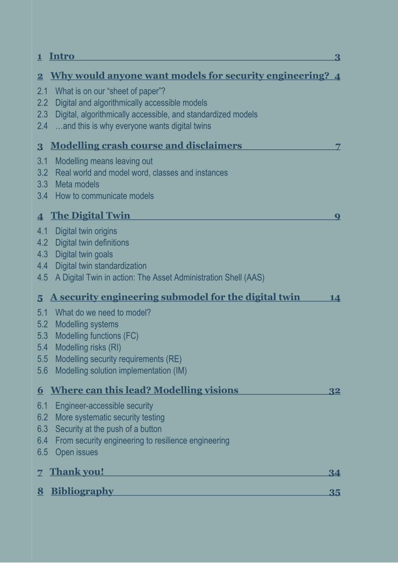
1 Intro 3
2 Why would anyone want models for security engineering? 4
2.1 What is on our “sheet of paper”?
2.2 Digital and algorithmically accessible models
2.3 Digital, algorithmically accessible, and standardized models
2.4 …and this is why everyone wants digital twins
3 Modelling crash course and disclaimers 7
3.1 Modelling means leaving out
3.2 Real world and model word, classes and instances
3.3 Meta models
3.4 How to communicate models
4 The Digital Twin 9
4.1 Digital twin origins
4.2 Digital twin definitions
4.3 Digital twin goals
4.4 Digital twin standardization
4.5 A Digital Twin in action: The Asset Administration Shell (AAS)
5 A security engineering submodel for the digital twin 14
5.1 What do we need to model?
5.2 Modelling systems
5.3 Modelling functions (FC)
5.4 Modelling risks (RI)
5.5 Modelling security requirements (RE)
5.6 Modelling solution implementation (IM)
6 Where can this lead? Modelling visions 32
6.1 Engineer-accessible security
6.2 More systematic security testing
6.3 Security at the push of a button
6.4 From security engineering to resilience engineering
6.5 Open issues
7 Thank you! 34
8 Bibliography 35
3
On Modelling for Security Engineering as a Submodel of The Digital Twin
1 Intro In an earlier blog post [1], I wished we had a common model for security, something that is
to security engineers what P&I diagrams are to process engineers. Something that our minds
could “walk around in” to better understand our systems, assumptions, risks, and security
design choices.
I promised to make a first draft proposal for models to be used in security engineering, which
is what I’m doing in this paper.
We’ll be modelling the security engineering workflow based on the Layered Blueprints
security engineering procedure model, and we’ll create security engineering system models,
making use of familiar and widely accepted concepts and standards like data flow diagrams,
attack graphs, MITRE ATT&CK®, ISO/IEC 27001 and ISA/IEC 62443 along the way. The
models are not re-inventing or replacing any of these established concept; they just bring
them to the table all together.
For modelling syntax, we’ll rely on a digital twin implementation, the Asset Administration
Shell (AAS), that you will get to know today. I promise it’s more exciting than its name. To
dock on to the industry-overarching digital twin efforts is a great way of ensuring security
engineering is in lockstep with all other engineering domains it needs to collaborate with,
which is especially important for OT respectively automation security engineering.
We will see why now is a perfect time to begin consolidating our models, catching up on the
modelling backlog that the security engineering domain has accumulated compared to other
engineering domains.
Engineering models are a highly dynamic field, and so is security engineering. Throughout
2020, some of the missing pieces fell into place, leaving the topic mature enough to at least
give this paper a first shot. Well, of course the missing pieces did not just fall into place. They
were hammered into place by smart people who did a lot of work I can build on in this paper.
You’ll meet them throughout the paper.
I’m not claiming to propose anything remotely as mature as P&ID diagrams here. It’s the best
shot at modelling security I have right now, and it is meant to evolve. I’m looking forward to
all of your better ideas that I may provoke you to utter after you’ve read this paper. In fact,
provoking you into uttering all your modelling ideas may be the No. 1 reason I’m writing this.
So, I hope you brought a bit of time to let your mind wander through the new security model
landscape it is going to meet today.
4
On Modelling for Security Engineering as a Submodel of The Digital Twin
2 Why would anyone want models for
security engineering?
2.1 What is on our “sheet of paper”?
If you could show only one piece of paper summarizing your current security problem and
how you solve it — what would be on it?
Security engineers don’t have an easy answer to that question, because we have no common,
agreed-on model.
In other domains, engineers learn that if they are to solve a problem, first thing they do is to
strip the problem down to a model — and for good reason. Models help to channel thinking.
They de-clutter a problem from all irrelevant aspects and show the world from the
perspective out of which the problem becomes the clearest.
An engineer uses a model to distill a problem and all its relevant boundary conditions in a
single sheet of paper, and then she begins to work with that model, expands, molds and
kneads it, until it contains a solution. In the end, the model showcases a solution, printable
onto a sheet of paper that can be handed on to a fellow engineer to help him understand
problem as well as solution, and also catalyzes discussions.
So the fact security engineering does not have an easy answer to the “sheet-of-paper-
question” actually means that we’re lacking a tool that helps us thinking.
In an industry that is quick to develop new tools that promise to replace us thinking, a tool
that facilitates, even incentivizes us thinking would help decluttering and deflating problems
and solutions. Also, in an industry where security engineering is one additional side-hustle for
engineers who are paid to do “real engineering” besides security, every little tool that helps
makes security engineering clearer, more accessible.
A common model could be such a thinking-enabler. Also, it could be one milestone for
bringing security engineering closer to “playing with the big kids”, to being a full engineering
discipline like automation engineering, electrical engineering, process engineering,
hydraulics… – they all have their models already.
And it’s not that we would not have any models in security. We have lots of models for
attacks. We have some models for risk. We sometimes model data flow, and we definitely
model assets and networks. But we rarely connect the dots of all these separate models to
form a bigger picture. Mostly, no straightforward answer to “why do we have this
configuration in place and what additional risks would we have if we deleted it?” can be
found in those models.
And we certainly do not have models we all agree on, that we could hand over to a fellow
engineer even from a different company, and she would understand our security problem.
5
On Modelling for Security Engineering as a Submodel of The Digital Twin
2.2 Digital and algorithmically accessible models
Now take all these advantages a pen-on-paper model would already have and think about
what would happen if we made them digital and thus electronically accessible.
If the model was not only electronically, but also algorithmically accessible, it would be
possible for the systems we model – which happen to also be electronic – could read and add
information to their own models. “Implement new firewall rule” (with underlying security
requirement and risk attached)? Security at the push of a button? How cool would that be?
It would also mean we could take the model and try out things on a model instead of on the
real thing. Models are a trailblazer for being more courageous with finding out how a system
reacts to uncertainty, be it through penetration tests or chaos engineering experiments.
A popular claim for the ICS asset inventory and detection tools is “you can’t secure what you
don’t see”, leading to “you need visibility of your network”. Of course all of this is true. But
visibility does not just mean a smart way of actively and / or passively collecting data from all
your devices. Visibility also means creating smart ways that help humans comprehend all this
data and do something with it. And this exactly is what models are for.
2.3 Digital, algorithmically accessible, and standardized
models
Now imagine that our digital security model would not just be a model security engineers
agree on, but its underlying principles would be agreed on by all other engineering domains
as well; that it would be standardized. That would mean there would be interoperability
between digital twins of different assets, regardless of technical domain, manufacturer or
lifecycle phase.
Imagine you, responsible for security at a plant, could freely search all the information
contained in a P&I diagram or electrical plans – just as if you were googling not the internet,
but your plant.
That would mean that we could make use of models that already exist in other engineering
domains, or even collaboratively engineer systems. It would be a tool for considering security
as early as possible during the engineering process, dubbed “security by design”.
Also, a standardized model would mean that we could get rid of the information silos we’ve
built everywhere around a plant. At the moment, security engineers are making things worse
buy building additional information silos using different sets of security tool. It’s a shame
because security is such an interdisciplinary domain, truly in need of all the engineering
information already in place: Electrical plans? Building architecture? Safety engineering?
Process engineering? All relevant for security. We should be an integrative force for
engineering processes, instead of adding yet another engineering silo.
But that’s not the end of the story. A standardized, electronically accessible model could also
enable different systems who use the same standardized model to talk to each other: “Hey
6
On Modelling for Security Engineering as a Submodel of The Digital Twin
PLC, give me your newest configuration – nope, does not look good, please replace with the
one from 10am.”
2.4 …and this is why everyone wants digital twins
All these visions are of course not primarily security visions. They are a fundamental part of
the smart manufacturing or industry 4.0 concept – of smartly interconnected systems in an
Industrial Internet of Things that facilitate new value-added processes.
In order to technically implement this concept, common-format, electronically and
algorithmically accessible models for every asset in a “digital factory” are a cornerstone.
These models have become known as “digital twins”.
All this means we’re in luck. Now is exactly the best time there to build a security model,
because the whole industry is about to build models to result in a common “bigger whole” –
in digital twins.
For most engineering domains, that means transferring their established models into a digital
twin version. For security, it means we first have to create any models at all and then transfer
them into a digital twin version. Or we could define them directly in a digital-twin-compatible
way, which is what this paper will aim to do.
7
On Modelling for Security Engineering as a Submodel of The Digital Twin
3 Modelling crash course and disclaimers
3.1 Modelling means leaving out
Mark Twain once said that writing was easy; you only had to cross out the wrong words.
Modelling is much the same. To begin our modelling journey, it’s important to keep in mind
that we’re not looking for the world formula. We’re only looking for a representation that
highlights all aspects of reality that are relevant for a specific purpose.
To be very clear: security engineering models will lack a lot of information that is important
for a million different purposes. They will be unbearably incomplete. But that’s their whole
point. As the adage goes: All models are wrong, but some are useful.
3.2 Meta models
A meta model is a model that defines how to model. What sounds like an academic exercise
actually makes a lot of sense, especially if you want to have a standardized way of modelling.
A model’s syntax and semantics are the most basic characteristics to be defined in its meta-
model.
A model’s syntax is the way a model uses symbols, phrases, interpunctuation, graphic
elements, or whatever it consists of. A model’s syntax could for example define that a
“relationship” is being modelled by drawing an arrow.
A model’s semantics is the way a model conveys its meaning. If a model says “relationship” –
what does that mean? Does an arrow between A and B mean that A “belongs to” B or that A
“talks to” B?
3.3 How to communicate models
If you define a new model, you need to pick a form of presentation to get your ideas across.
You need to, well, model the model. As you have learned a second ago, using a model’s
meta-model seems to be a smart choice.
The problem with meta-models is that they are (must be) very formalized. Formalization – in
UML class diagrams, for example – is immensely important for defining a model, or a meta-
model, unambiguously. However, these formal representations are not very intuitive to read
(if you’re not the total modelling nerd, that is).
So in this paper, we make a compromise. I will use the basic syntax and semantics of the
digital twin (we’ll get to this in a moment), but in a kind of “pseudo-code” instead of the
formal modelling language as used in the digital twin’s – the Asset Administration Shell’s, to
be precise – meta model specification.
While the prime reason for this “pseudo-code” is understandability, the second important
reason is that the proposed model simply has not been formally designed yet. The Asset
8
On Modelling for Security Engineering as a Submodel of The Digital Twin
Administration Shell is a work in progress, these security models I’m presenting today are a
work in progress, and it did not seem smart to overly formalize a draft definition comprised
of two moving targets. So, you’ll be getting to know the pretty-picture-version of a security
engineering model today.
9
On Modelling for Security Engineering as a Submodel of The Digital Twin
4 The Digital Twin It does not make sense to roll out the entire digital twin concept here, but since we’re aiming
at modelling security directly in digital twin format, there are some digital twin basics we
need to cover upfront.
4.1 Digital twin origins
The digital twin concept originates from a 2002 presentation on product lifecycle
management by Michael Grieves [2], which introduced the idea of having systems in a “real
space” and mirror these same systems in a “virtual space”, with data measured from the real
systems flowing to the virtual space, and information gained from analyzing the virtual
system flowing back to the real space.
The digital twin concept has since been followed by many different researchers and
organizations. In fact, a popular joke among researches is that you only had to mention
“digital twin” somewhere in your research proposal for funding to flow freely. Naturally the
broad research activity brought about conflicting digital twin concepts and definitions. Since
the whole point of defining a digital twin model is that everyone uses the same model to
ensure interoperability, but there were conflicting parallel definitions, it was hard to decide
which model to go for. Besides, the standardized models were just not explicitly defined
enough to really use them.
2020 saw quite a bit of a digital twin consolidation, which is the reason we can feel confident
enough to start building upon the consolidated definitions.
4.2 Digital twin definitions
In February 2020, the Industrial Internet Consortium (IIC) published a white paper with the
goal of establishing a definition and a few basic design aspects [3]. The definition is
deliberately vague and has become widely accepted:
“A digital twin is a formal digital representation of some asset, process or system that
captures attributes and behaviors of that entity suitable for communication, storage,
interpretation or processing within a certain context.” [3]
Or shorter:
“Digital representation, sufficient to meet the requirements of a set of use cases” [4].
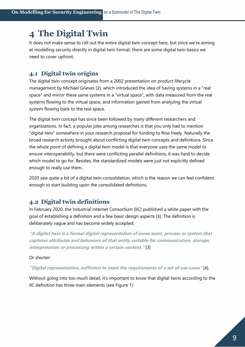
Without going into too much detail, it’s important to know that digital twins according to the
IIC definition has three main elements (see Figure 1):
10
On Modelling for Security Engineering as a Submodel of The Digital Twin
Figure 1: Digital twin main elements and ways of interaction, based on [3]
Data: A digital twin may contain data about its real-world twin throughout all
lifecycle phases.
Models: A digital twin may contain computational or analytic models required to
describe, understand, and predict the real-world twins’ states and behaviors.
Service interfaces (APIs): A digital twin may contain service interfaces for
applications or other digital twins to access its data and invoke its capabilities.
In a way, the digital twin “serves as a proxy that collects data centrally for every entity abd
then makes that information available for different areas of the business” [3]. Also, a digital
twin may be composed of other digital twins or have associations to other digital twins.
4.3 Digital twin goals
We roughly covered the digital twin goals in chapter 2, even though we did not call them
“digital twin goals” explicitly. The fundamental goal is still based on what Grieves introduced
almost 20 years ago: To have one digital represenation of an asset that contains and provides
all information about that asset throughout its entire lifecycle. This implies breaking down
information silos, because nowadays manufacturers and operators rarely have a common
information base, and even the operator has different information bases for maintenance and
operation, for example [3].
Based on that fundamental goal, several derivative goals may be mentioned [4] [3]:
Make information available to anyone (if authorized) at any time and in an organized
manner
Use the digital representation for analytics or even artificial intelligence in order to
simulate, predict, and optimize its real-world counterpart’s state and / or behavior
Enable collaborative engineering throughout lifecycle phasesand engineering
domains
11
On Modelling for Security Engineering as a Submodel of The Digital Twin
4.4 Digital twin standardization
As stated in chapter 2: the paramount aspect of a digital twin is its interoperability, which
only works if we manage to agree on a standardized implementation.
There are a couple of initiatives relevant to standardizing digital twins, some of which are still
under development. The digital factory framework in the IEC 62832 series [5], the IEC PAS
63088 defining the RAMI4.0 industry 4.0 reference model [6], the IIC Industrial Internet of
Things Reference Architecture [7] as well as the ISO 23247 series “Automation systems and
integration — digital twin framework for manufacturing” [8] all set the stage to harmonize
digital twins.
The one concept that to date provides most detail regarding actual digital twin
implementations is the asset administration shell, or short: AAS. It is driven by German
“Plattform Industrie 4.0”, and being standardized as IEC 63278 – Asset Administration Shell
for Industrial Applications (in Committee Draft stage at the time of this writing) [9].
The standard is not publicly available yet, but based on an international paper on the asset
administration shell structure published by institutions from France, Germany and Italy [10].
There are also detailed specifications available, fittingly named “Details of the Asset
Administration Shell”, the latest updates hot off the press just a couple of weeks ago [11] [12].
The digital twin has been aligned to the Industrial Internet Consortium’s reference
architectecture in a 2020 joint whitepaper between IIC and Plattform I4.0 [4], and the current
Committee Draft of ISO 23247 references the AAS concept as one way to describe a digital
twin – so at least all the standardization efforts don’t reinvent the wheel, but build upon one
another. Also, it is probably safe enough to say that the AAS concept is here to stay, which is
why it makes sense for us to get to know it a bit – and we’ll use some of its basic principles
for our security engineering models.
4.5 A Digital Twin in action: The Asset Administration Shell
(AAS)
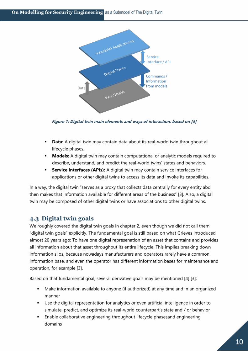
The name “Asset Administration Shell” is not going to win any
marketing contests. It sounds unpleasantly bureaucratic even
for German ears. But in its defense, the name becomes quite
memorable once the concept is visualized (see Figure 2).
Yes, the “admin shell” or “AAS”1, as people who’ve warmed
with the concept tenderly call it, really can be imagined as a
shell wrapped around an asset and containing all the asset’s
information.
1 In this paper, both „admin shell” and “AAS” are used interchangeably as short forms for “Asset
Administration Shell”.
Figure 2: Asset
Administration Shell
visualization
12
On Modelling for Security Engineering as a Submodel of The Digital Twin
4.5.1 Submodels
The most important thing you need to know about the admin shell is that it contains multiple
submodels. Submodels are a clever move when you don’t want to embark on the impossible
mission to find a model which all domains who could potentially use an AAS want to agree
on. Also, it fits in with our Twain quote saying we need to cross out all the information not
relevant to our respective model, because not every domain wants to see every bit of
information. In order to ensure at least the same domain uses the same submodels,
submodel templates can be defined.
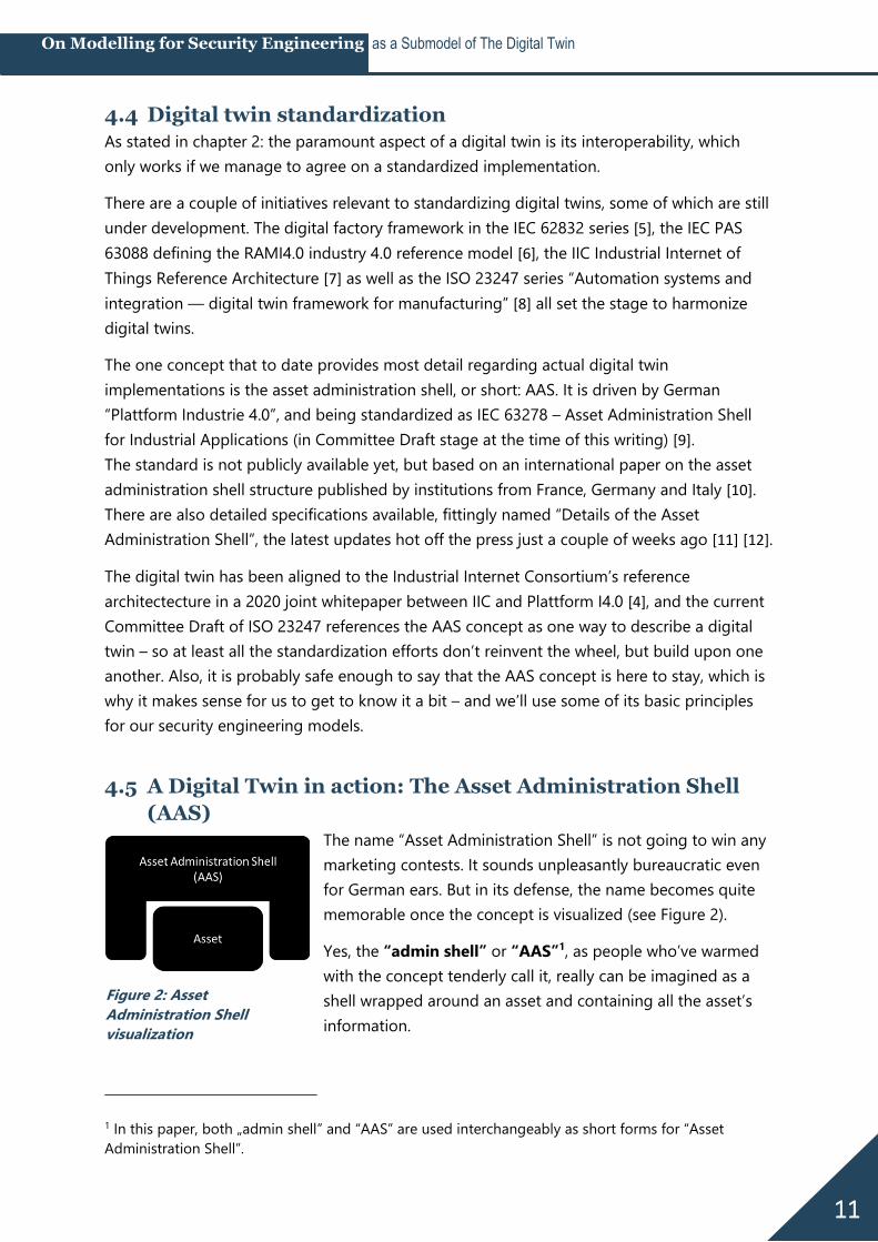
You see examples for submodels in Figure 3. The
submodel “Bill of Material” (BOM) has indeed been
officially named by Plattform I4.0 already, and we’ll
get to it in a moment, but the other submodels are
only examples we’re using here for demonstration
purposes. In fact, just this fall the very first submodel
example has been published – a proof of concept for
the AAS, including all information that would
otherwise be found on an assets nameplate in a
“digital nameplate” submodel [13].
4.5.2 Introducing a “security engineering” submodel
Let’s stop here for a moment to state that submodels are a blessing for us. We are free to
define our own security engineering submodel, to contain a perspective that is relevant for us
doing security engineering. But at the same time submodels can use information from other
submodels, so security engineers could for example request information from a submodel
containing an P&I diagram or a network diagram.
Security is really only one of the digital twin’s submodels among many others, just one small
piece in a “bigger whole”, and that makes the model we’re creating tremendously more
useful for avoiding data silos and supporting collaboration between engineering domains.
There’s much to be done in defining digital twin submodels – for all domains, not just
security engineering.
One side note in order to avoid confusion:
The IIC definition as well as the AAS meta-model do define security as an important aspect to
be considered for digital twins such as secure access to their content, secure data exchange
between digital twins, information authenticity, or secure and trustworthy deployment [4]. All
these aspects are about security OF the digital twin, while we are aiming to define models in
order to engineer security WITH the digital twin.
Figure 3: Asset Administration Shell
with potential Submodels
13
On Modelling for Security Engineering as a Submodel of The Digital Twin
4.5.3 Notes on AAS Deployment
The deployment of the AAS (i.e. where and in which format is the AAS’s data stored, what
protocols and data formats are used for data exchange, what tools are used for editing and
viewing the data) is out of scope for this paper.
However, it is good to know that the AAS is not an alternative, but an integration of existing
protocols and data formats.
The AAS concept distinguishes between accessing and exchanging information offline (i.e.
file-based) and exchanging information online respectively at runtime (i.e. using Application
Programming Interfaces / APIs) [4].
Depending on the lifecycle phase and purpose for data exchange, different serializations, i.e.
different ways to store and / or transmit the AAS data, are available. They can be chosen
freely depending on lifecycle phase and use case.
The serializations for passive offline file exchange are data formats: XML and JSON for file-
based exchange between different partners, AutomationML for engineering data exchange,
RDF for analytics. Also, a dedicated data exchange format for Asset Administration Shells,
AASX, is being defined.
For automated data exchange at runtime, communication protocol serializations are needed.
The currently considered options include OPC UA, http, and MQTT [4].
One final remark before we get around to create AAS models for security engineering: There
are open-source tools available (and still under development) for implementing AAS
protoypes: The AASX server, client, and package explorer under https://github.com/admin-
shell as well as the BaSyx platform under https://www.eclipse.org/basyx/.
14
On Modelling for Security Engineering as a Submodel of The Digital Twin
5 A security engineering submodel for the
digital twin
5.1 What do we need to model?
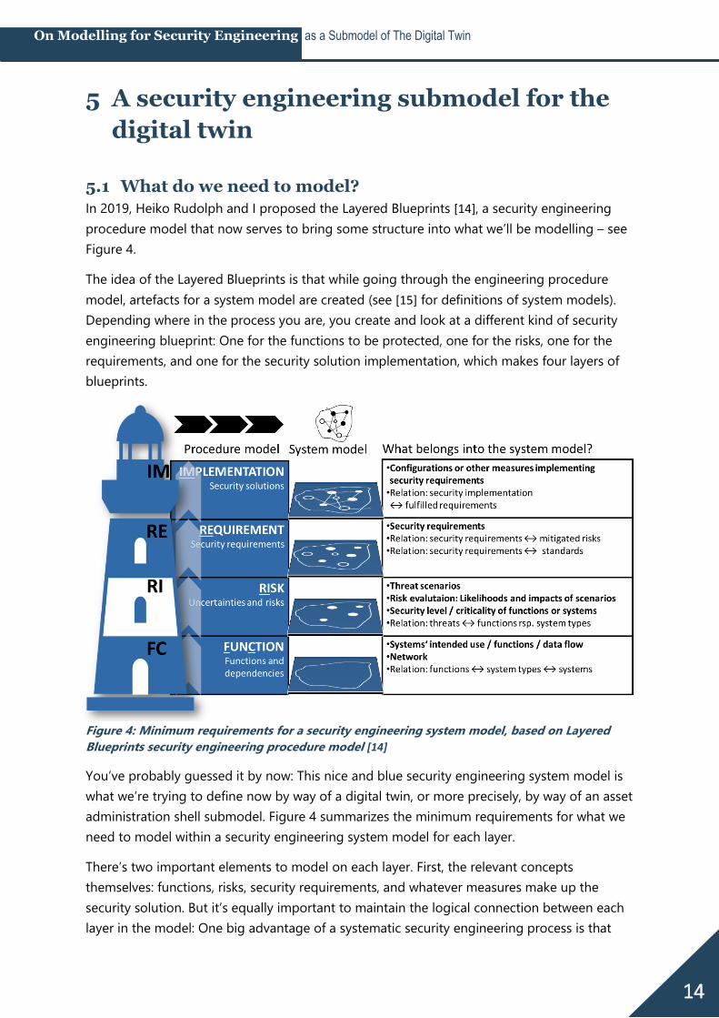
In 2019, Heiko Rudolph and I proposed the Layered Blueprints [14], a security engineering
procedure model that now serves to bring some structure into what we’ll be modelling – see
Figure 4.
The idea of the Layered Blueprints is that while going through the engineering procedure
model, artefacts for a system model are created (see [15] for definitions of system models).
Depending where in the process you are, you create and look at a different kind of security
engineering blueprint: One for the functions to be protected, one for the risks, one for the
requirements, and one for the security solution implementation, which makes four layers of
blueprints.
Figure 4: Minimum requirements for a security engineering system model, based on Layered
Blueprints security engineering procedure model [14]
You’ve probably guessed it by now: This nice and blue security engineering system model is
what we’re trying to define now by way of a digital twin, or more precisely, by way of an asset
administration shell submodel. Figure 4 summarizes the minimum requirements for what we
need to model within a security engineering system model for each layer.
There’s two important elements to model on each layer. First, the relevant concepts
themselves: functions, risks, security requirements, and whatever measures make up the
security solution. But it’s equally important to maintain the logical connection between each
layer in the model: One big advantage of a systematic security engineering process is that
15
On Modelling for Security Engineering as a Submodel of The Digital Twin
you can always trace back why someone made a certain security decision, and based on
which assumptions.
There’s a weird firewall rule? Well, let’s see which security requirement it fulfills, and why that
requirement is relevant to us at all: Is there a risk mitigated by it? Do we need to comply to
any standard for it? And if there’s a risk – which function is impacted? How bad would it be if
we disabled the firewall rule?
A good security engineering system model must be able to swiftly answer all these questions,
and this is why every layer has also the requirement to have the relation to the layer below
modelled in our digital twin submodel “security”:
At the implementation layer, this means we want to model a relation between a
solution and the requirements they fulfill. At the requirements layer, we want to know
if a requirement relates to a standard or framework and / or if it is there to mitigate a
risk.
At the risk layer in turn, the relation goes back to the functions or systems are
affected by a risk.
And at the function layer, we want a relation from our more abstract security
engineering view, that probably has happened based on abstract system types and
functions, not all the system instances, back to the instances. This information is
probably available in another digital twin submodel which may contain everything an
asset inventory contains.
With these requirements set, we can begin modelling. We go from the bottom layer up to the
top.
5.2 Modelling systems
Sure, we want the “one sheet of paper” we can hand over to a fellow security engineer. Here’s
the trouble: Security never begins with a blank sheet of paper. If there’s no system to secure
in the first place, security is pointless.
This is going to be difficult. I really do not want to solve the overall problem of how to model
systems in general here, which is also a
problem that has been solved over and
over – for different use cases. But of
course we need a basis for what we’re
securing, something that keeps our
security models firmly grounded.
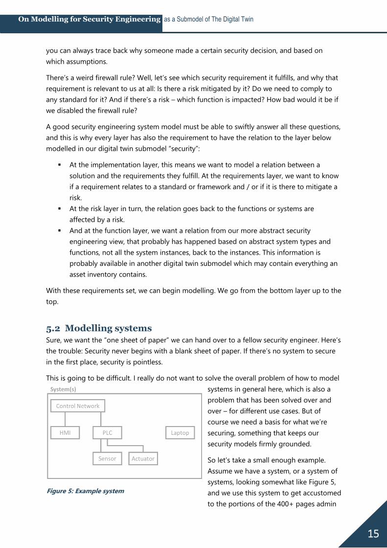
So let’s take a small enough example.
Assume we have a system, or a system of
systems, looking somewhat like Figure 5,
and we use this system to get accustomed
to the portions of the 400+ pages admin
Figure 5: Example system
16
On Modelling for Security Engineering as a Submodel of The Digital Twin
shell specification that we make use of for our security models. We see a control network
(could also be a fieldbus), an HMI and a PLC connected to this network, some field devices
connected directly to the PLC, and a laptop, which is mobile and not permanently connected
to anything.
Let’s see how we could get this modelled in our newly found admin shell world. For starters,
it’s good to know that really anything, or any entity, can have its own administration shell, as
long as it has unique information that needs to be modelled and managed separately from
other entities. Administration shells can be on different levels of detail, from representing an
entire plant to only one piece of piping.
5.2.1 Bill of Materials (BOM) submodel
Here’s where the “Bill of Material” (BOM) submodel comes into play. If there’s an admin shell
for a plant and an admin shell for a piece of piping, you’d want to tell your plant admin shell
that the piece of piping belongs to it – and vice versa.
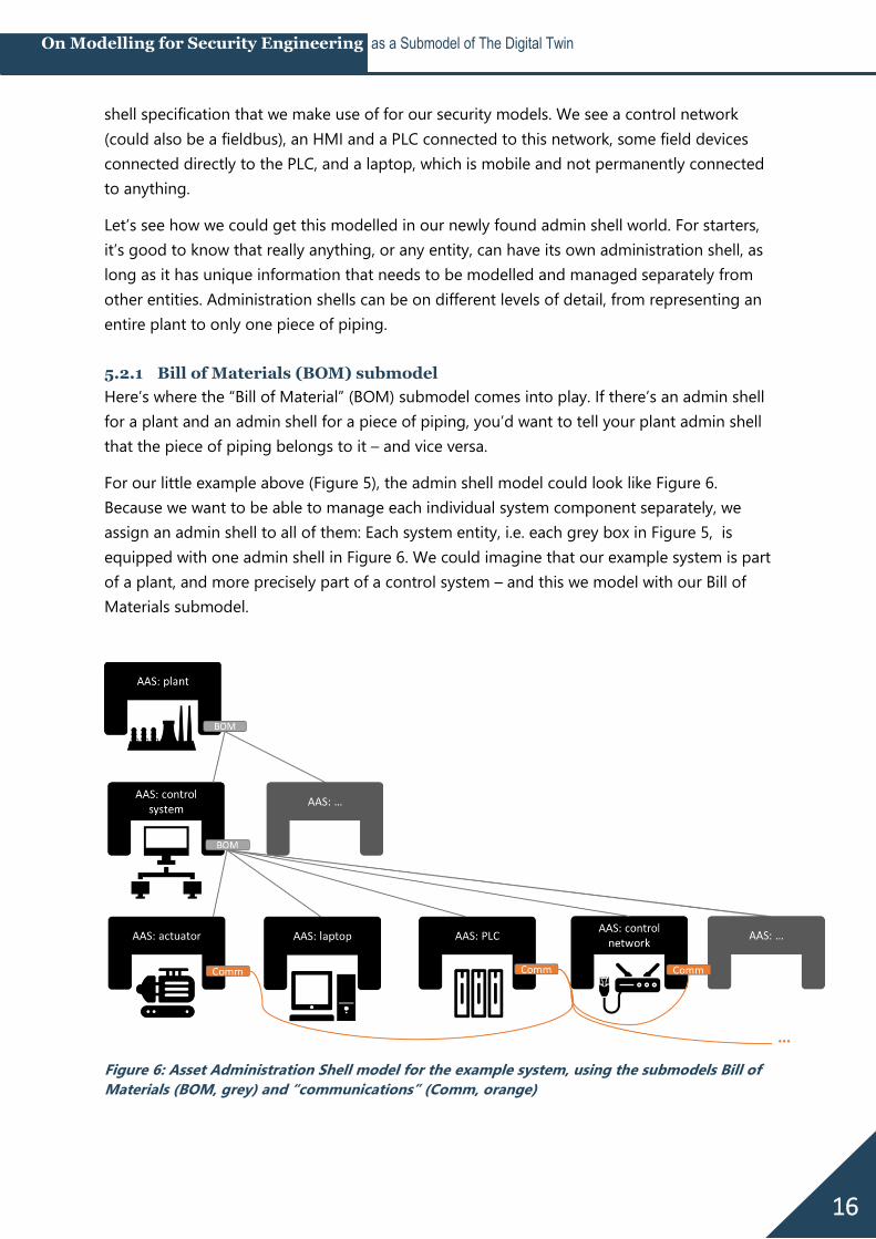
For our little example above (Figure 5), the admin shell model could look like Figure 6.
Because we want to be able to manage each individual system component separately, we
assign an admin shell to all of them: Each system entity, i.e. each grey box in Figure 5, is
equipped with one admin shell in Figure 6. We could imagine that our example system is part
of a plant, and more precisely part of a control system – and this we model with our Bill of
Materials submodel.
Figure 6: Asset Administration Shell model for the example system, using the submodels Bill of
Materials (BOM, grey) and “communications” (Comm, orange)
17
On Modelling for Security Engineering as a Submodel of The Digital Twin
5.2.2 “Communication” submodel
Now we have to admit our BOM model is missing some information from Figure 5. Our
system components’ admin shells are all part of a control system, fine enough, but we don’t
see which ones are connected and which ones aren’t. We can’t see the the laptop, for
example, does not have any connections right now, while the PLC has three.
So let’s decide this information is going to be stored in another submodel, which does not
exist yet in the AAS, so I call it “Communication”, leaving this in quotation marks to make
clear it’s a preliminary name. So now each of the asset administration shells for which we
want to model communication gets a “communications” submodel, colored orange in Figure
6, which models the connections to other admin shells. That way, we can see Figure 6 that
our PLC has three connections, to the control network, the actuator, and the sensor (not
pictured), while the laptop has none.
5.3 Modelling functions (FC)
I’m an advocate for using functions, not single assets or systems, as a basis for all things
security engineering. A function combines technical system components, human system
components, and interactions between system components that are needed in order to serve
a defined purpose.
Thinking in functions, not systems, may feel unfamiliar at first, but for security engineering
makes sense for a lot of reasons (see [16] for more details). Among others you create a lower
number of single units to process in risk analyses, you get a more intuitive way of talking
about what’s important to keep a plant running, and you explicitly include humans in your
analysis.
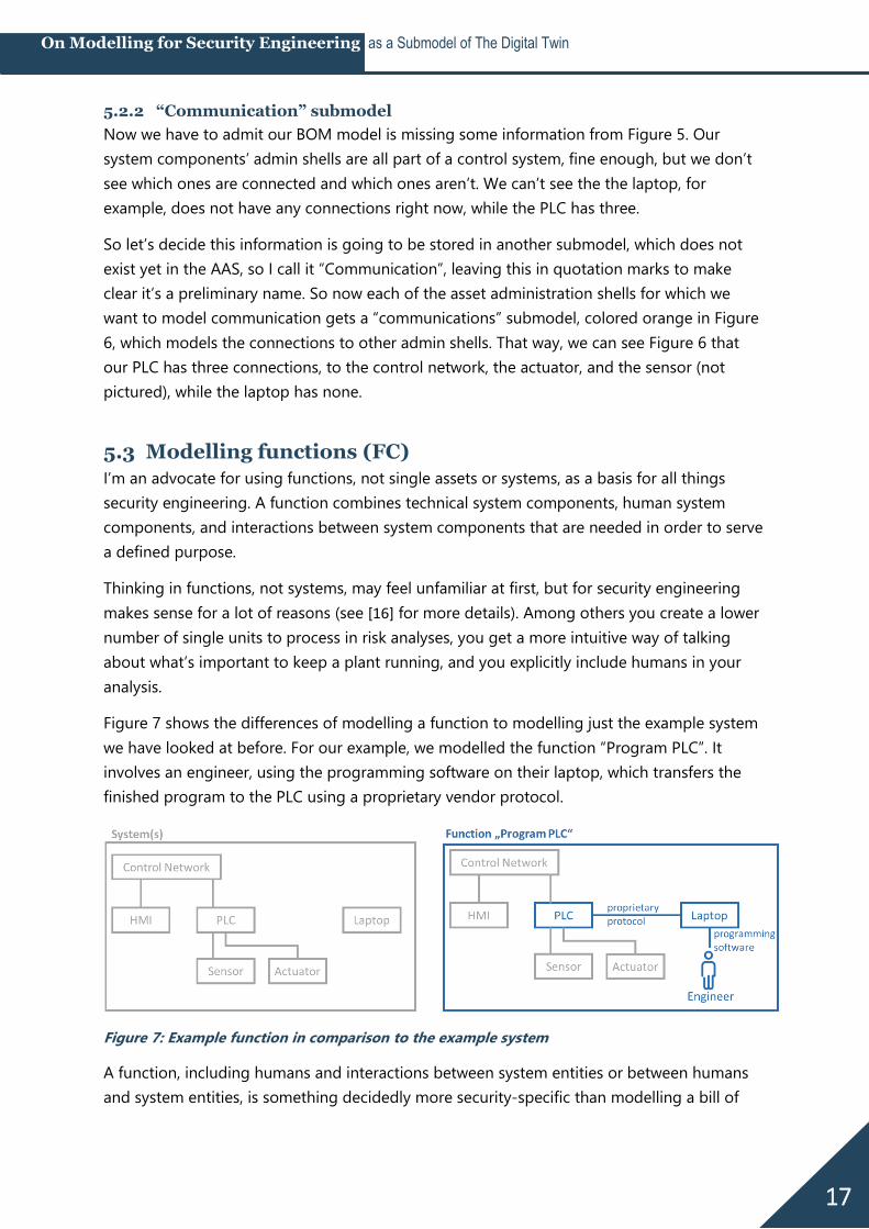
Figure 7 shows the differences of modelling a function to modelling just the example system
we have looked at before. For our example, we modelled the function “Program PLC”. It
involves an engineer, using the programming software on their laptop, which transfers the
finished program to the PLC using a proprietary vendor protocol.
Figure 7: Example function in comparison to the example system
A function, including humans and interactions between system entities or between humans
and system entities, is something decidedly more security-specific than modelling a bill of

18
On Modelling for Security Engineering as a Submodel of The Digital Twin
materials or communication interfaces. This is why functions are the first concept we’re
modelling within our submodel “security”.
5.3.1 Modelling the function layer in the AAS submodel “security engineering”
In order to model the function concept, we need to include a few additional principles and
modelling elements in our Asset Administration Shell model:
Lowest common denominator princple
Including humans
Including purpose and criticality
Including system interactions and their order
Including relations to system instances
All of these are illustrated in Figure 8. I’ll slowly walk you through it in the following sections.
Figure 8: Asset Administration Shell model for the example function, here: submodels Bill of
Materials (BOM, grey), “communications” (Comm, orange) and the function (FC) layer of the
submodel “Security” (Sec.FC, blue)
5.3.2 “Lowest common denominator” principle
There is a principle that is crucial to understand when dealing with digital twins: The entire
concept is based on the approach that information is stored in a decentralized way, as close
to the asset it affects as possible. This was straightforward for a bill of materials and for
communication interfaces, but with turning to functions deserves special attention.
Take our example function “program PLC”: Of all the system components in Figure 7 – in
which admin shell would you place the information about that function? For the “security
19
On Modelling for Security Engineering as a Submodel of The Digital Twin
engineering” submodel, as a rule of thumb I’m proposing a “principle of the lowest common
denominator”: place a piece of information at the lowermost admin shell that contains
all entities relevant for that piece of information.
Now having modelled a bill of materials pays off: We can place the function at the lowermost
admin shell that contains all entities relevant to the function. In our example (Figure 8), that
would be the control system, which contains PLC, laptop – and the engineer.
5.3.3 Including humans
Speaking of the engineer: We had no engineer modelled in our system model in Figure 6. But
for security engineering models, you can’t really get around modelling humans. So an admin
shell for the human role “engineer” was added in Figure 8. This is no problem: admin shells
can represent not only technology, but also processes, organizations and persons.
You might also have noted that we added a connection from the engineer to his laptop and
from the laptop directly (not via the control network) to the PLC to include all connections
relevant for the function “program PLC”.
5.3.4 Including purpose and criticality
A function could have attributes we wanted to model. These could really be anything, but the
minimum to expect for security engineering would be a function description detailing the
function’s purpose within the organization’s mission and a criticality or security level
measuring the impact of the function’s manipulation or failure. T
he attributes are stored in the “Sec.FC” submodel of the control system admin shell (see blue
“function attributes” box in Figure 8), since it’s the lowermost admin shell that contains all
entities that belong to the function.
5.3.5 Including system interactions and their order (data flow)
Next, we need to model entity interactions – mostly communication – and their order. This
corresponds to the concept of data flow diagrams. First, the engineer uses the programming
software on his laptop, and then he flashes it onto the PLC via a proprietary procotol, in our
example.
This sequence of interactions for the function “Program PLC” is modelled within the “Sec.FC”
submodel of the control system’s AAS (visualized by blue arrows and numbers in Figure 8).
The “Sec.FC” submodels of engineer’s, laptop’s, and PLC’s admin shells however only contain
a reference to the “Program PLC” function to save the information which functions they
belong to.
5.3.6 Including relations to system instances
The last requirement we had for modelling functions was that they needed to include
relations to the system instances that are implied. So far, we modelled only the system type, a
PLC, while in reality there are hundreds of PLCs (which we assume are all programmed the
20
On Modelling for Security Engineering as a Submodel of The Digital Twin
way we just modelled in the “Program PLC” function). The asset administration shell
specification includes an option for distinguishing between “types” and “instances” [11], so
it’s not a problem to have separate admin shells for both a generic PLC class and a concrete
Siemens S7 PLC instance which may for example have an IP address of 192.168.1.20 as an
identifier.
We don’t actively use the instance admin shells for our security engineering process, but our
security submodel should include a reference that makes clear which instance admin shells
are represented by a type admin shape.
In Figure 8, this is modelled for the PLC, which includes an exemplary reference to a Siemens
and a Schneider PLC instance. Since the instances are not pictured, the references point to
the figure’s rim, indicating they would end at asset instance admin shells modelled elsewhere.
“Elsewhere” could for example be an AAS-compatible asset inventory tool.
5.4 Modelling risks (RI)
5.4.1 Attack graphs
The risk layer is the one where the most groundwork for modelling already exists, and also
the biggest focus of the security community – and rightfully so. Threat scenarios are
commonly modelled in attack graphs, as introduced in 1999 by Bruce Schneier [17] for IT
security and adapted for OT security multiple times, as the risk analysis overview study by
Cherdantseva et al observed [18].
This is not the right place to do a full meta-study of threat modelling methods, and I don’t
claim to be scientifically accurate when I say: Attack graphs or graphs in general, are the most
systematic way of modelling threat scenarios to date. They also fall on fertile ground with
engineers, because they are used to suchlike trees from functional safety methods like fault
trees.
Also, using attack graphs as models have two major advantages as models: As human-
readable models, they are well suited to be visualized, and for machine-readable models, lots
of algorithms to process and analyze graphs exist, the reason for that being the many
technical problems that are modelled by using graphs: Navigation, routing, and social
networks are only some examples.
The only problem with attack trees for security is that they theoretically end in an infinite
number of potential paths through the tree, which makes them very suitable for academic
analysis, but less suitable for real-world risk analyses where people still have a real job
besides modelling attacks.
There are two ways to handle that problem: First, prioritize by focusing on highest
consequences first, and second, limit the attack graph flexibility by making use of kill chain
models or attack categorization knowledge bases like MITRE ATT&CK®.
21
On Modelling for Security Engineering as a Submodel of The Digital Twin
5.4.2 Consequences first
The first is to think about the end of the attack tree first. If you define the consequence that
your attack tree is supposed to result in and break them down into attacker goals before
starting to model scenarios, you at least eliminate all the academically interesting scenarios
leading to laughably irrelevant consequences.
Good examples for this principle is the adaptation of attack trees for SCADA systems by Byres
et al [19] or INL’s consequence-driven, cyber-informed engineering (CCE) methodology ([20]
– we’re all still waiting for the book on CCE!).
Byres et al are carefully defining the attacker’s goal (and sub-goals) before beginning to
model attack graphs, CCE calls for identification of the highest-consequence events before
proceeding to map kill chains to systems.
Let’s define a high-consequence event for our example function. High-consequence events
typically are industry-specific, so for this example we assume that we’re in a drinking water
utility, and our exemplary high-consequence event for the function “program PLC” would be
that the control logic got altered to add too much of a chemical to the drinking water.
5.4.3 Kill chain and attack categorization
The second way to handle the problem of infinite modelling possibilities is to constrain the
modelled threat scenario to closer align to feasibility, reality – or at least empiricsm by
utilizing frameworks to structure attacks based on observation of real attacks, like the cyber
kill chain [21] or – more elaborate and by now widely accepted – MITRE ATT&CK [22], more
specifically the ICS version published at the beginning of 2020 [23]. Structuring attack graphs
based on these frameworks results in limiting the options for which attack technique can
follow which one, and which technique works on which kind of target system.
MITRE ATT&CK® includes information on both, and Jan Hoff has spent a large part of his
master thesis [24] translating the MITRE ATT&CK for ICS techniques structure into attack
graphs. We’ll build upon his modelling work in a minute.
But first, if we want to use the ATT&CK knowledge base, we need to map our high-
consequence event, which serves as the ultimate goal for our attack graph, to MITRE
ATT&CK. For our purposes, it’s enough to know two two things about ATT&CK: Tactics
represent the attacker’s tactical objective, or the “why”, while techniques describe how an
attacker achieves this objective [22].
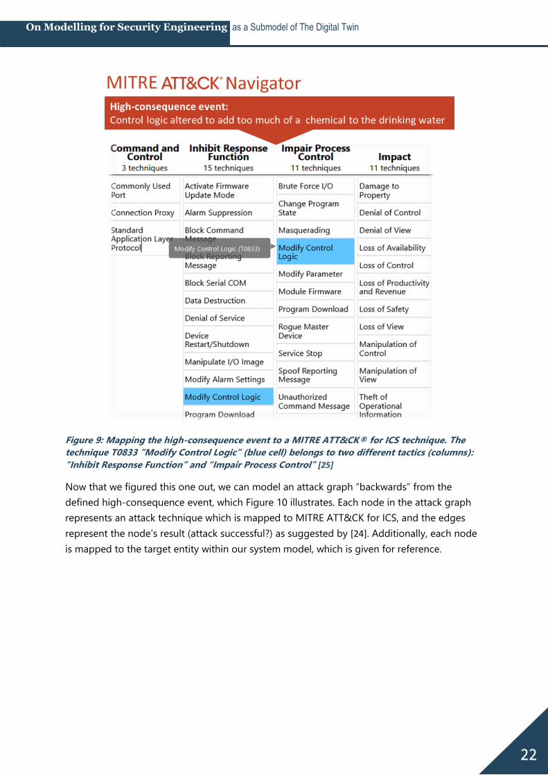
As we can see in Figure 9, there’s a suitable MITRE ATT&CK technique for the high-
consequence event we defined earlier: “T0833 - Modify Control Logic” (marked blue). The
technique belongs to two different tactics (columns in Figure 9): “Inhibit Response Function”
and “Impair Process Control”. In our case, manipulating PLC logic in order to contaminate
drinking water would belong to the latter.
22
On Modelling for Security Engineering as a Submodel of The Digital Twin
Figure 9: Mapping the high-consequence event to a MITRE ATT&CK® for ICS technique. The
technique T0833 “Modify Control Logic” (blue cell) belongs to two different tactics (columns):
“Inhibit Response Function” and “Impair Process Control” [25]
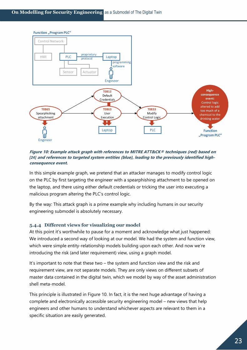
Now that we figured this one out, we can model an attack graph “backwards” from the
defined high-consequence event, which Figure 10 illustrates. Each node in the attack graph
represents an attack technique which is mapped to MITRE ATT&CK for ICS, and the edges
represent the node’s result (attack successful?) as suggested by [24]. Additionally, each node
is mapped to the target entity within our system model, which is given for reference.
23
On Modelling for Security Engineering as a Submodel of The Digital Twin
Figure 10: Example attack graph with references to MITRE ATT&CK® techniques (red) based on
[24] and references to targeted system entities (blue), leading to the previously identified high-
consequence event.
In this simple example graph, we pretend that an attacker manages to modify control logic
on the PLC by first targeting the engineer with a spearphishing attachment to be opened on
the laptop, and there using either default credentials or tricking the user into executing a
malicious program altering the PLC’s control logic.
By the way: This attack graph is a prime example why including humans in our security
engineering submodel is absolutely necessary.
5.4.4 Different views for visualizing our model
At this point it’s worthwhile to pause for a moment and acknowledge what just happened:
We introduced a second way of looking at our model. We had the system and function view,
which were simple entity-relationship models building upon each other. And now we’re
introducing the risk (and later requirement) view, using a graph model.
It’s important to note that these two – the system and function view and the risk and
requirement view, are not separate models. They are only views on different subsets of
master data contained in the digital twin, which we model by way of the asset administration
shell meta-model.
This principle is illustrated in Figure 10. In fact, it is the next huge advantage of having a
complete and electronically accessible security engineering model – new views that help
engineers and other humans to understand whichever aspects are relevant to them in a
specific situation are easily generated.
24
On Modelling for Security Engineering as a Submodel of The Digital Twin
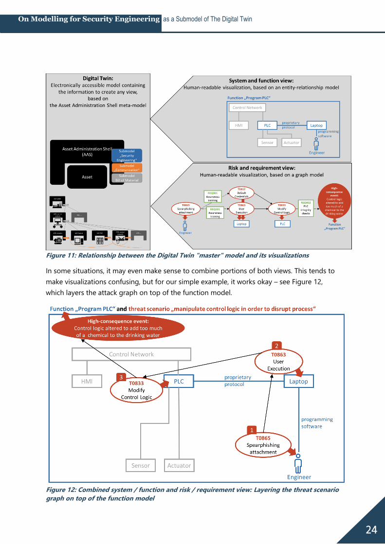
Figure 11: Relationship between the Digital Twin "master" model and its visualizations
In some situations, it may even make sense to combine portions of both views. This tends to
make visualizations confusing, but for our simple example, it works okay – see Figure 12,
which layers the attack graph on top of the function model.
Figure 12: Combined system / function and risk / requirement view: Layering the threat scenario
graph on top of the function model
25
On Modelling for Security Engineering as a Submodel of The Digital Twin
5.4.5 Modelling the risk layer in the AAS submodel “security engineering”
Now for the last step of modelling risks: Bringing it all together in our admin shell “master
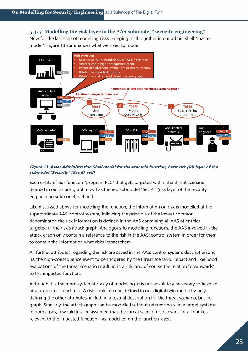
model”. Figure 13 summarizes what we need to model:
Figure 13: Asset Administration Shell model for the example function, here: risk (RI) layer of the
submodel “Security” (Sec.RI, red)
Each entity of our function “program PLC” that gets targeted within the threat scenario
defined in our attack graph now has the red submodel “Sec.RI” (risk layer of the security
engineering submodel) defined.
Like discussed above for modelling the function, the information on risk is modelled at the
superordinate AAS: control system, following the principle of the lowest common
denominator: the risk information is defined in the AAS containing all AAS of entities
targeted in the risk’s attack graph. Analogous to modelling functions, the AAS involved in the
attack graph only contain a reference to the risk in the AAS: control system in order for them
to contain the information what risks impact them.
All further attributes regarding the risk are saved in the AAS: control system: description and
ID, the high-consequence event to be triggered by the threat scenario, impact and likelihood
evaluations of the threat scenario resulting in a risk, and of course the relation “downwards”
to the impacted function.
Although it is the more systematic way of modelling, it is not absolutely necessary to have an
attack graph for each risk. A risk could also be defined in our digital twin model by only
defining the other attributes, including a textual description for the threat scenario, but no
graph. Similarly, the attack graph can be modelled without referencing single target systems.
In both cases, it would just be assumed that the threat scenario is relevant for all entities
relevant to the impacted function – as modelled on the function layer.
26
On Modelling for Security Engineering as a Submodel of The Digital Twin
5.5 Modelling security requirements (RE)
5.5.1 Attack-defense graphs
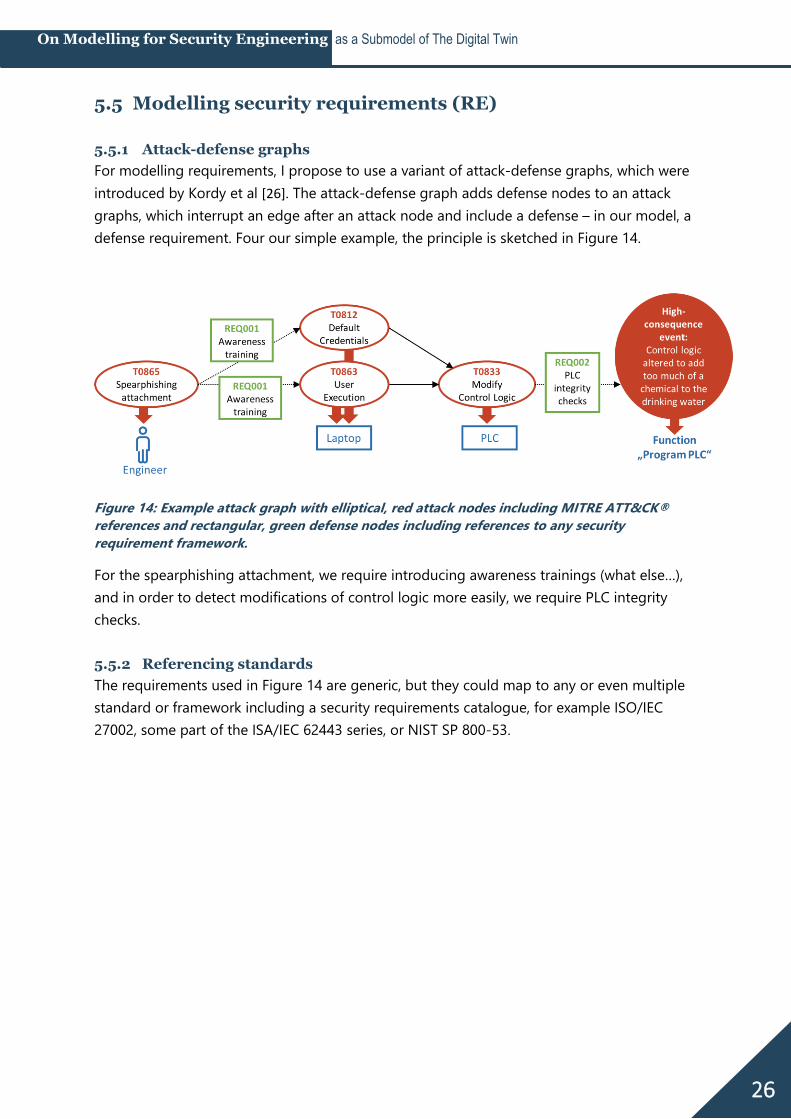
For modelling requirements, I propose to use a variant of attack-defense graphs, which were
introduced by Kordy et al [26]. The attack-defense graph adds defense nodes to an attack
graphs, which interrupt an edge after an attack node and include a defense – in our model, a
defense requirement. Four our simple example, the principle is sketched in Figure 14.
Figure 14: Example attack graph with elliptical, red attack nodes including MITRE ATT&CK®
references and rectangular, green defense nodes including references to any security
requirement framework.
For the spearphishing attachment, we require introducing awareness trainings (what else…),
and in order to detect modifications of control logic more easily, we require PLC integrity
checks.
5.5.2 Referencing standards
The requirements used in Figure 14 are generic, but they could map to any or even multiple
standard or framework including a security requirements catalogue, for example ISO/IEC
27002, some part of the ISA/IEC 62443 series, or NIST SP 800-53.
27
On Modelling for Security Engineering as a Submodel of The Digital Twin
5.5.3 Modelling the requirements layer in the AAS submodel “security
engineering”
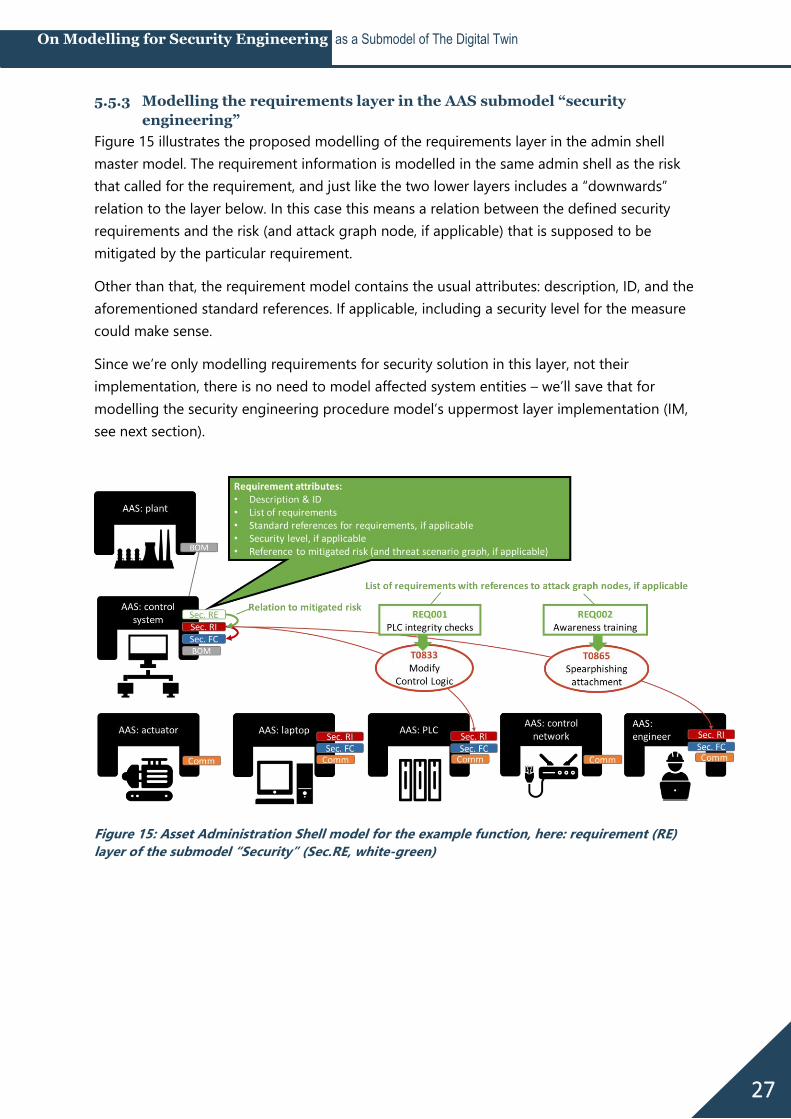
Figure 15 illustrates the proposed modelling of the requirements layer in the admin shell
master model. The requirement information is modelled in the same admin shell as the risk
that called for the requirement, and just like the two lower layers includes a “downwards”
relation to the layer below. In this case this means a relation between the defined security
requirements and the risk (and attack graph node, if applicable) that is supposed to be
mitigated by the particular requirement.
Other than that, the requirement model contains the usual attributes: description, ID, and the
aforementioned standard references. If applicable, including a security level for the measure
could make sense.
Since we’re only modelling requirements for security solution in this layer, not their
implementation, there is no need to model affected system entities – we’ll save that for
modelling the security engineering procedure model’s uppermost layer implementation (IM,
see next section).
Figure 15: Asset Administration Shell model for the example function, here: requirement (RE)
layer of the submodel “Security” (Sec.RE, white-green)
28
On Modelling for Security Engineering as a Submodel of The Digital Twin
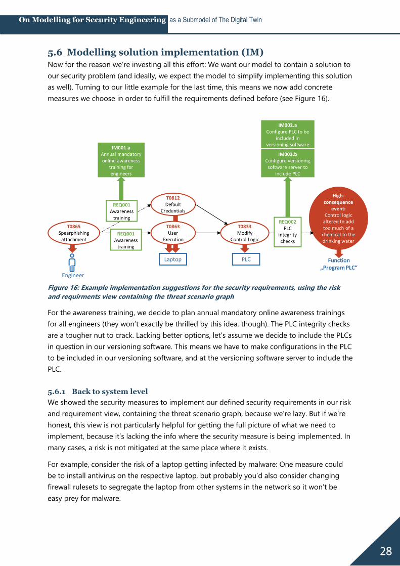
5.6 Modelling solution implementation (IM)
Now for the reason we’re investing all this effort: We want our model to contain a solution to
our security problem (and ideally, we expect the model to simplify implementing this solution
as well). Turning to our little example for the last time, this means we now add concrete
measures we choose in order to fulfill the requirements defined before (see Figure 16).
Figure 16: Example implementation suggestions for the security requirements, using the risk
and requirments view containing the threat scenario graph
For the awareness training, we decide to plan annual mandatory online awareness trainings
for all engineers (they won’t exactly be thrilled by this idea, though). The PLC integrity checks
are a tougher nut to crack. Lacking better options, let’s assume we decide to include the PLCs
in question in our versioning software. This means we have to make configurations in the PLC
to be included in our versioning software, and at the versioning software server to include the
PLC.
5.6.1 Back to system level
We showed the security measures to implement our defined security requirements in our risk
and requirement view, containing the threat scenario graph, because we’re lazy. But if we’re
honest, this view is not particularly helpful for getting the full picture of what we need to
implement, because it’s lacking the info where the security measure is being implemented. In
many cases, a risk is not mitigated at the same place where it exists.
For example, consider the risk of a laptop getting infected by malware: One measure could
be to install antivirus on the respective laptop, but probably you’d also consider changing
firewall rulesets to segregate the laptop from other systems in the network so it won’t be
easy prey for malware.
29
On Modelling for Security Engineering as a Submodel of The Digital Twin
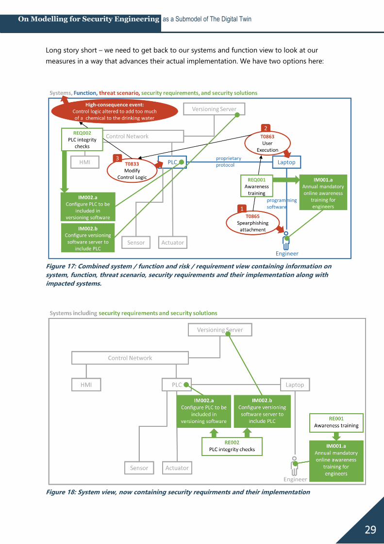
Long story short – we need to get back to our systems and function view to look at our
measures in a way that advances their actual implementation. We have two options here:
Figure 17: Combined system / function and risk / requirement view containing information on
system, function, threat scenario, security requirements and their implementation along with
impacted systems.
Figure 18: System view, now containing security requirments and their implementation
30
On Modelling for Security Engineering as a Submodel of The Digital Twin
Figure 17 shows the combined system / function and risk / requirement view with the
threat scenario graph layered on top of the function model – which gets a bit
complex by now, but shows all “downwards” references (systems, functions, threat
scenario graph, and requirements).
Figure 18 in comparison is cleaned up to contain only the system view, now enhanced
with the security solution to be implemented. The affected function is not necessarily
required for implementing measures systems.
Note that for both views, we needed to add a new system to our system model – the
versioning server. This is an important observation: Of course, security solutions sometimes
call for not only changing configurations of existing entities in our function layer model, but
modifying the system model in general by adding, removing, our moving around entities.
Now which view of both views is the better? The good news is: you get to choose. If in doubt,
choose both. They are based on the same digital twin “master model” anyway, and this is
precisely what we’re going to look at next.
5.6.2 Modelling the implementation layer in the AAS submodel “security
engineering”
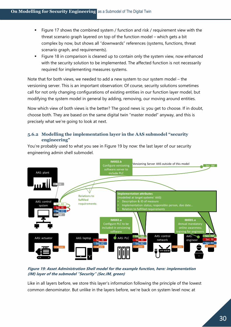
You’re probably used to what you see in Figure 19 by now: the last layer of our security
engineering admin shell submodel.
Figure 19: Asset Administration Shell model for the example function, here: implementation
(IM) layer of the submodel “Security” (Sec.IM, green)
Like in all layers before, we store this layer’s information following the principle of the lowest
common denominator. But unlike in the layers before, we’re back on system level now; at
31
On Modelling for Security Engineering as a Submodel of The Digital Twin
least in our example, each configuration or other measure can be implemented at exactly one
of our defined systems.
Including the PLC in the versioning software includes configurations within the PLC and the
Versioning Server (which we do not have on our current excerpt of admin shells, because it’s
a newly introduced system). The annual online training for engineers get stored in the
engineer’s admin shell (assuming that HR has the training plans for each role stored in its
AAS). This makes for “Sec.IM” submodels defined in the AAS: PLC, AAS: Versioning Server (not
pictured) and AAS: engineer.
There may be additional attributes stored with each implementation measure: description
and ID, sure, but also implementation status, a responsible person, and maybe a due date.
As always, we include the reference to what’s happened so far: in this case, this means a
reference to the admin shell where the triggering requirement was defined for the security
measures we’re now modelling – which is the AAS: control system.
32
On Modelling for Security Engineering as a Submodel of The Digital Twin
6 Where can this lead? Modelling visions
6.1 Engineer-accessible security
It has often been said that we need to reduce the security burden on engineers. At the same
time, security depends on the engineers’ system knowledge, so if “reducing the burden”
means handing security over to someone else, I firmly believe this is the wrong way. But if
“reducing the burden” means making security more accessible to engineers by making
security methods more systematic and less reliant on “twenty years of experience” and
hackerdom – well, that would be quite the achievement.
Modelling security engineering is a way of disenchanting it, and that is actually a good thing.
Engineers have all the knowledge they need in order to do security engineering, and they
also have their most important security tool: their brain. All we need is clearer methodology
and tools to help them thinking and applying all their system knowledge – instead of
replacing them thinking.
6.2 More systematic security testing
Byres, Franz, and Miller mentioned it as a side-note already in 2004 [19]: More systematic
threat modelling can ultimately be translated into tests against real-world devices, networks,
and protocol implementations.
In 2020, so-called security chaos experiments were getting attention through the work of
Kelly Shortridge and Aaron Rinehart, who wrote a book on security chaos engineering [27],
and Ginger Wright at INL, who talked about chaos experiments at S4x20 [28] and later in Dale
Peterson’s videocast [29].
The approach of chaos engineering is to accept that our systems’ complexity cannot be
handled by “thinking it through” anymore, but that we need to inject uncertainties in order to
actually experience – and measure – what happens. Well, having sound security models is a
very good precondition to designing sound security chaos experiments. Also, models have
the potential to bring structure to all kinds of security tests, including penetration tests, by
better defining what to test and how to measure success.
6.3 Security at the push of a button
One of the most commonly mentioned problems that the digital twin concept is set to fight
are data silos. Removing them, and fully implementing the vision of digital twins
autonomously talking to each other has great potential for actually reducing the security
burden through making security solution implementation efficient.
If we had a digital twin including all the information we set it up with in this paper AND free
to communicate and send commands to its real-world twins or their respective
administration tools – that would mean that we could build true security blueprints
33
On Modelling for Security Engineering as a Submodel of The Digital Twin
containing all relevant security configurations for a certain system type, hit a button, and roll
out those security configurations – or at least conduct an automatic compliance check
against these requirements. Implementing security at the push of a button.
6.4 From security engineering to resilience engineering
Modelling security engineering in the digital twin means transforming it into the language
automation engineers use for their “own” engineering, making security engineering results
accessible to other domains and vice versa.
Maybe the most courageous vision of all is that security, if finally made accessible to
engineers by using their language, their models, and consequently their tools, may grow up
as an engineering domain. Not only does this open the opportunity for security to become a
natural part in the larger, already highly interdisciplinary automation engineering process, but
also to form better synergies – instead of rivalries – with related disciplines.
To take a popular example that happens to consume a lot of my time: Why do we have to
debate if considering malicious attacks for functional safety systems is done by security or
safety engineers? Why do we have to debate which is a sub-domain of which?
After the Fukushima disaster, Kazuo Furuta coined the term “resilience engineering” [30]. At
least for OT security, it’s about time that we identify with the larger goal of resilient systems
instead of nitpicking what exactly is in the scope of engineering “secure” systems.
6.5 Open issues
There’s still a lot of unsolved issues. All modelling approaches need review and refinement.
The interfaces to other engineering domains need to be defined. And, most importantly, the
“pseudo-code” notation of asset administration shell, in pretty pictures instead of formal
specification language, needs to be formalized.
34
On Modelling for Security Engineering as a Submodel of The Digital Twin
7 Thank you! The admin shell is work in progress, and using it for modelling security engineering is
uncharted terrain. Therefore, I’m grateful that Dr. Thomas Tauchnitz patiently helped
combining the moving target of digital twins with the moving target of security engineering
models. Thomas has a remarkable talent for transforming dry modelling work into pretty
pictures that aid explaining. Thanks to “Mr. AAS” Dr. Michael Hoffmeister guiding us through
the jungle of newly published AAS papers.
Thank you, Prof. Dr.-Ing. Rainer Drath, for rooting for electronically accessible engineering
models with never-ceasing enthusiasm. I felt privileged that as a side-effect of the lengthy
process of applying for a research project together, your pointed questions helped sharpen
the idea of what exactly we want to model over and over.
For the risk modelling part, I owe a thank you to Jan Hoff who managed to rekindle my
skeptical viewpoint of attack graphs with his master thesis [24]. Go ahead and read it!
Even though chaos engineering is just a side show in this paper, I would like to compliment
Kelly Shortridge and Aaron Rinehart for their book on chaos engineering [27]. It is a great
inspiration and was one of the nudges to finally get this paper written.
Speaking of getting this paper written: I know how lucky I am that my employer admeritia is
accepting and actively encouraging me spending time on non-billable work, “for world
peace”.
The most important thank you, however, belongs to everyone who has reached out to me in
reaction to the initial P&ID blog post [1]. I was overjoyed to see how many likeminded people
are missing adequate security models, and how many ideas we all have what we could build
upon. Please never stop pointing me to anything that has remotely to do with modelling.
35
On Modelling for Security Engineering as a Submodel of The Digital Twin
8 Bibliography [1] S. Fluchs, “Security Engineering Needs a P&I Diagram,” fluchsfriction, Apr. 2020.
https://fluchsfriction.medium.com/security-engineering-needs-a-p-i-diagram-
8cb390dba00b.
[2] M. Grieves, “Origins of the Digital Twin Concept,” 2016, doi:
10.13140/RG.2.2.26367.61609.
[3] Industrial Internet Consortium (IIC), “Digital Twins for Industrial Applications -
Definition, Business Values, Design Aspects, Standards and Use Cases.” Feb. 2020,
[Online]. Available:
https://www.iiconsortium.org/pdf/IIC_Digital_Twins_Industrial_Apps_White_Paper_2020-
02-18.pdf.
[4] B. Boss et al., “Digital Twin and Asset Administration Shell Concepts and Application in
the Industrial Internet and Industrie 4.0.” 2020, [Online]. Available:
https://www.plattform-i40.de/PI40/Redaktion/EN/Downloads/Publikation/Digital-Twin-
and-Asset-Administration-Shell-Concepts.pdf?__blob=publicationFile&v=7.
[5] IEC, “IEC 62832 series: Industrial-process measurement, control and automation -
Digital factory framework.” [Online]. Available:
https://webstore.iec.ch/publication/65858.
[6] IEC, “IEC PAS 63088:2017 - Smart manufacturing - Reference architecture model
industry 4.0 (RAMI4.0).” 2017, [Online]. Available:
https://webstore.iec.ch/publication/30082.
[7] Industrial Internet Consortium (IIC), Ed., “The Industrial Internet of Things Volume G1:
Reference Architecture.” Jun. 2019, [Online]. Available:
https://www.iiconsortium.org/pdf/IIRA-v1.9.pdf.
[8] ISO, “ISO 23247 series: Automation systems and integration — Digital Twin framework
for manufacturing.” [Online]. Available: https://www.iso.org/standard/75066.html.
[9] IEC, “IEC 63278-1 (CD): Asset administration shell for industrial applications - Part 1:
Administration shell structure.” 2020.
[10] French Ministry of Economy and Finances, Alliance Industrie du Futur, German Federal
Ministry for Economic Affairs and Energy (BMWi), Plattform Industrie 4.0, WG reference
architectures, standards and norms in the ZVEI (German Electrical and Electronics
industry e.V.), and Italian Ministero dello Sviluppo Economico, Eds., “The Structure of
the Administration Shell: Trilateral Perspectives from France, Italy and Germany.” Mar.
2018, [Online]. Available: https://download.afnet.fr/ASD2018/ASD2018-6A-
TheStructureOfTheAdministrationShell-
TrilateralPerspectivesFromFranceItalyAndAGermany.pdf.
[11] ZVEI and Plattform I4.0, “Details of the Asset Administration Shell - Part 1 The
exchange of information between partners in the value chain of Industrie 4.0 (Version
3.0RC01).” Nov. 22, 2020, Accessed: Nov. 25, 2020. [Online]. Available:
https://www.plattform-
i40.de/PI40/Redaktion/DE/Downloads/Publikation/Details_of_the_Asset_Administration_
Shell_Part1_V3.html.
36
On Modelling for Security Engineering as a Submodel of The Digital Twin
[12] ZVEI and Plattform I4.0, Eds., “Details of the Asset Administration Shell - Part 2 –
Interoperability at Runtime – Exchanging Information via Application Programming
Interfaces (Version 1.0RC01).” .
[13] Plattform I4.0, “AAS Submodel Templates - ZVEI Digital Nameplate for industrial
equipment (Version 1.0).” 2020, [Online]. Available: https://www.plattform-
i40.de/PI40/Redaktion/EN/Downloads/Publikation/Submodel_templates-
Asset_Administration_Shell-digital_nameplate.pdf?__blob=publicationFile&v=2.
[14] S. Fluchs and H. Rudolph, “Making OT security engineering deserve its name - A guide
to security engineering for OT engineers,” CONTROL global, p. 24, 2019, [Online].
Available: https://www.controlglobal.com/articles/2019/making-ot-security-
engineering-deserve-its-name.
[15] U. Epple, “Begriffliche Grundlagen der leittechnischen Modellwelt,” atp, p. 9, 2008.
[16] S. Fluchs, “Think in functions, not in systems! - 10 reasons why functions facilitate
security (short version),” fluchsfriction, Jun. 2020.
https://fluchsfriction.medium.com/think-in-functions-not-in-systems-6afeb675b5d2.
[17] B. Schneier, “Attack Trees,” Dr. Dobb’s Journal, Dec. 1999, [Online]. Available:
https://www.schneier.com/academic/archives/1999/12/attack_trees.html.
[18] Y. Cherdantseva et al., “A review of cyber security risk assessment methods for SCADA
systems,” Computers & Security, vol. 56, pp. 1–27, Feb. 2016, doi:
10.1016/j.cose.2015.09.009.
[19] E. J. Byres, M. Franz, and D. Miller, “The Use of Attack Trees in Assessing Vulnerabilities
in SCADA Systems,” Proceedings of the international infrastructure survivability
workshop, p. 9, 2004, [Online]. Available:
https://www.researchgate.net/profile/Eric_Byres/publication/228952316_The_use_of_att
ack_trees_in_assessing_vulnerabilities_in_SCADA_systems/links/546cfaf10cf26e95bc3caa
bf/The-use-of-attack-trees-in-assessing-vulnerabilities-in-SCADA-systems.pdf.
[20] S. G. Freeman, C. St Michel, R. Smith, and M. Assante, “Consequence-driven cyber-
informed engineering (CCE),” Idaho National Laboratory, Boise, Oct. 2016. Accessed:
Jan. 17, 2019. [Online]. Available: http://www.osti.gov/servlets/purl/1341416/.
[21] M. Assante and R. M. Lee, “The Industrial Control System Cyber Kill Chain.” 2015,
[Online]. Available: https://www.sans.org/reading-room/whitepapers/ICS/industrial-
control-system-cyber-kill-chain-36297.
[22] B. E. Strom, A. Applebaum, D. P. Miller, K. C. Nickels, A. G. Pennington, and C. B.
Thomas, “MITRE ATT&CK: Design and Philosophy.” 2018, [Online]. Available:
https://www.mitre.org/sites/default/files/publications/pr-18-0944-11-mitre-attack-
design-and-philosophy.pdf.
[23] MITRE, “ICS ATT&CK Matrix.” 2020, [Online]. Available:
https://collaborate.mitre.org/attackics/.
[24] J. Hoff, “Creating Attack Graphs for Adversary Emulation, Simulation and Purple
Teaming in Industrial Control System (ICS) Environments,” FernUniversität in Hagen,
2021.
[25] MITRE, “MITRE ATT&CK Navigator v4.1.” Accessed: Dec. 30, 2020. [Online]. Available:
https://mitre-attack.github.io/attack-navigator/.
37
On Modelling for Security Engineering as a Submodel of The Digital Twin
[26] B. Kordy, S. Mauw, S. Radomirović, and P. Schweitzer, “Foundations of Attack–Defense
Trees,” in Formal Aspects of Security and Trust, vol. 6561, P. Degano, S. Etalle, and J.
Guttman, Eds. Berlin, Heidelberg: Springer Berlin Heidelberg, 2011, pp. 80–95.
[27] A. Rinehart and K. Shortridge, Security Chaos Engineering - Gaining Confidence in
Resilience and Safety at Speed and Scale. O’Reilly, 2020.
[28] V. Wright, “Test Effect Payloads for Tuning ICS Incident Response,” presented at the
S4x20, Jan. 2020, [Online]. Available: https://www.youtube.com/watch?v=6RhPWxTLiSw.
[29] V. Wright and D. Peterson, “Chaos Engineering In ICS with Ginger Wright,” Dec. 09,
2020, [Online]. Available: https://www.youtube.com/watch?v=XeAFdouFeTs.
[30] K. Furuta, “Resilience Engineering,” in Reflections on the Fukushima Daiichi Nuclear
Accident, J. Ahn, C. Carson, M. Jensen, K. Juraku, S. Nagasaki, and S. Tanaka, Eds. Cham:
Springer International Publishing, 2015, pp. 435–454.