Embed Size (px)
Citation preview


ON LOAD TAP CHANGERSRS 12
TECHNICAL DATA
Hyundai Heavy IndustriesCo. Bulgaria
2017-3
EA 676.1/17 EN
2
Contents 1. Basic characteristics .......................................................................................................................... 3
1.1. Basic technical data .............................................................................................................. 3 1.2. Rated through current (Iu), rated step voltages (Ui), rated switching capacity (PstN) ......... 4 1.3. Electrical and mechanical endurance ................................................................................... 5 1.4. Insulation level ..................................................................................................................... 6
2. Review of the different RS12 types .....................................................................................................9
2.1. Main dimensions ................................................................................................................... 9 2.2. Basic connection diagrams .................................................................................................10 2.2.1. Designation and range of regulation .....................................................................10 2.2.2. Examples of basic connection diagrams ...............................................................12
3. Appendices ........................................................................................................................................ 14
3.1. Overall dimension drawings of OLTCs ............................................................................. 14 3.2. Additional drawings of OLTCs .......................................................................................... 14 3.3. RS 12 – driving shafts arrangement ....................................................................................14
Notes:
1) This technical data catalog is intended to be used by transformer designers as well as oth-er technical personnel responsible for maintenance, diagnostics and operation of OLTCs.
2) HHI-Bulgaria reserves the right to make changes in the overall dimension drawings and connection diagrams without prior notice. Updated drawings are provided as part of the technical documentation received by the customer at the time of the product delivery; updated drawings can be provided also to potential customers on request.
3) TheOLTCismanufacturedaccordingtothespecificdataintheorderspecificationsheetfilledinbytheclient.
4) HHI-Bulgaria is not responsible for the client’s improper selection of an OLTC.

3
1. Basic characteristicsThe OLTCs of Hyundai Heavy Industries Co. Bulgaria (HHIB) meet the requrements of the IEC 60214-1 standard.1.1. Basic technical data
Table 1OLTC type RS12 – I/ D/Y – 200/400 A
Number of phases and application 1 phase – at any point on the winding
3 phase – at any point on the winding
3 phase – in the neutral
Maximum rated through current, (A) 200 400 200 400 200 400Short circuit withstand current, (kA)
R.m.s. value (3 s duration) 4 6 4 6 4 6
Peak value 10 15 10 15 10 15Maximum rated step voltage per phase (V) 2500 2000 2500 2000 2500 2000Rated step capacity (kVA) 1) 500 800 500 800 500 800Rated frequency (Hz) 50/60
Insulation to earth
Highest voltage for equipment – insulation to earth and between phases forΔconnection,(kVr.m.s)2)
Rated separate source AC withstand voltage, 1 min duration (kV, r.m.s.)Rated lighting impulse withstand voltage(kV,1,2/50μs)
Number of operating positions Without change-over selector – 14With a change-over selector – 27
OLTC inner insulation level See section 1.4
Oil pressure in the OLTC oil compartmentOperating oil pressure up to 0,3 x 10⁵ Pa
(testing pressure – 0,6 x 10⁵ Pa) Vacuum-proof for drying.
Siphon for draining the oil from the diverter switch oil vessel Standard equipment
Drying In vacuum furnace – up to 110°CIn kerosene vapor – up to 125°C
Displaced by the OLTC volume in dm3 (approx.) 3 phase OLTC – 160÷205Single phase OLTC – 95÷110
OilfillingquantityoftheOLTCoilcompartment Vs in dm3 (approx.)
3 phase OLTC – 128÷175Single phase OLTC – 70÷90
Weight 4), (kg) 3 phase OLTC – 165÷195Single phase OLTC – 110÷140
1) For more details see section 1.2.2)InaccordancewithIEC60214-1,highesteffectivevalueforphase-to-phasevoltageinathree-phase
system for which an on-load tap changer is designed with respect to its insulation.3) For OLTC type RS12 – 3 and 1 phase in the neutral only.4) Exact weight is available in the attached particular drawing.
Notes: 1. Minimum volume of the conservator, considering the temperature oil expansion when the temperaturechangesfrom-30°Cto+100°C:∆V=0,1Vs+5(dm3).
2. The RS12 OLTC can operate with a rated load at oil temperature from -25°C to +105°C.
41,5 72,5 123 3)
110 140 230
250 350 550

EA 676.1/17 EN
4
1.2. Rated through current (Iu), rated step voltages (Ui), rated switching capacity (PstN)
Theratedtroughcurrentanditsrelevantratedstepvoltagearedefinedbythecurve,representingtherated switching capacity (Fig. 1).
Fig. 1: Step capacities (rated through current Iu [A]; rated step voltages Ui [V])
The step voltage is also limited by the maximum voltage across the regulating winding, determined by theinsulationtestsoftheselector.Thehighestworkingvoltageacrosstheregulatingwinding,definedaccording to the criteria above shall not exceed the values as follows:
Number of tap positionsWorking voltage across the regulating winding,
(kV)RS 12
10 tap selector contacts 3012 tap selector contacts 3014 tap selector contacts 27,5

5
In case of overexcitation of the transformer, the maximum step voltage can be increased with 10% under the condition that the step capacity is limited to its rated value.ThespecificcommutationregimesareclarifiedinthetechnicaldatacatalogforallHHIBOLTCs.
1.3. Electrical and mechanical endurance.The electrical endurance of the diverter switch arcing contacts depends on many factors, connected with the operating conditions. The number of operations until inspection and contact replacement, obtained experimentallyatmaximumratedthroughcurrent,relevantstepvoltageandcos(φ)=1isgivenintable2.
Table 2: Electrical and mechanical endurance
OLTCNumber of switching operations for OLTC
RS12-Y/Δ-200 RS12-Y/Δ-400RS12-I-200 RS12-I-400
Rated current, A Up to 100 Up to 200 Up to 250 Up to 400Number of switching operations till inspection 2)
100 000 70 000 100 000 50 000 70 000 50 000
Number of switching operations till replacement of contacts
200 000400 000 1) 200 000 200 000
400 000 1) 200 000
Mechanical endurance-number of switching operations
800 000
1) special design 2) or in operation for maximum: - 6 years for RS 12 – Y – 200 A; - 6 years for RS 12 – Y – 400 A; - 3 years for RS 12 – D – 200, 400 A

EA 676.1/17 EN
At through current less than the maximum rated through current Ium, the number of switching operations untilreplacementofthecontactsisdefinedbythecurvefromfig.2.
Fig. 2: Number of switching operations until contact replacement
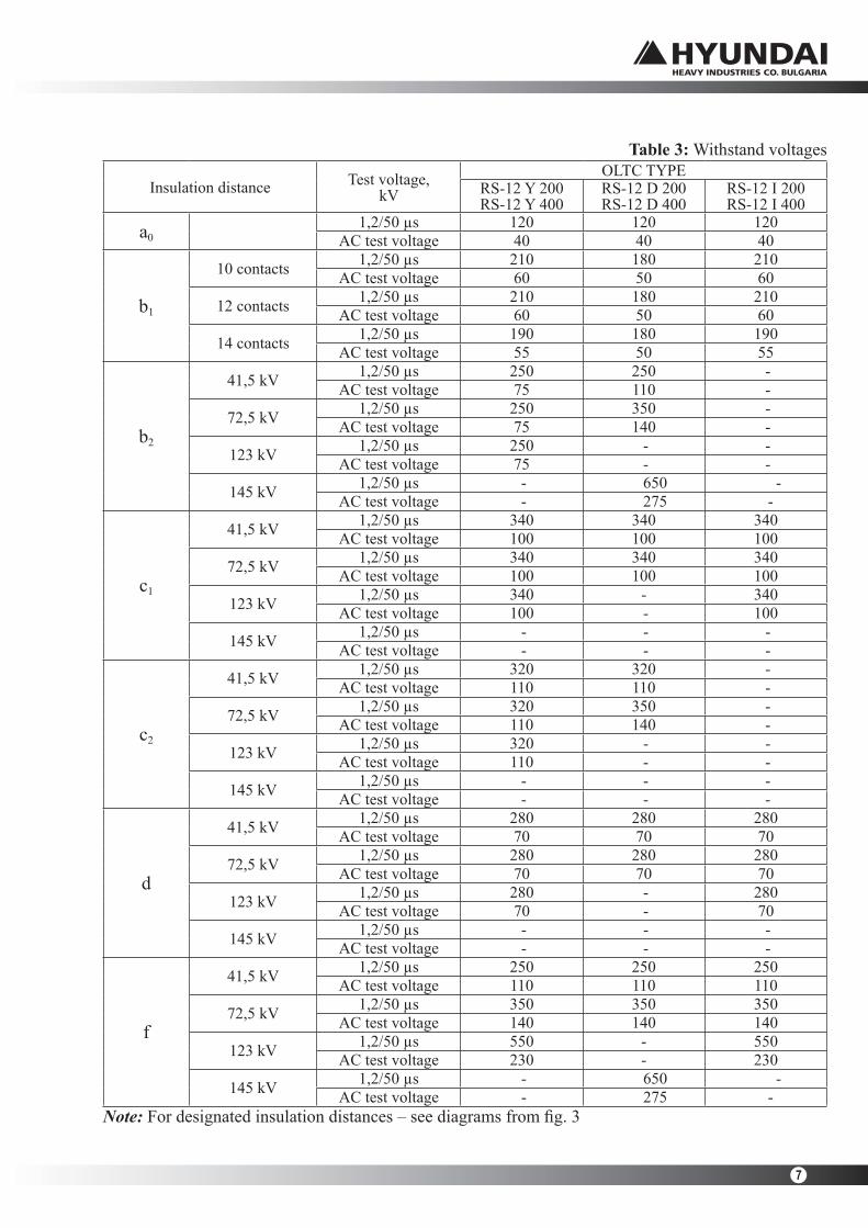
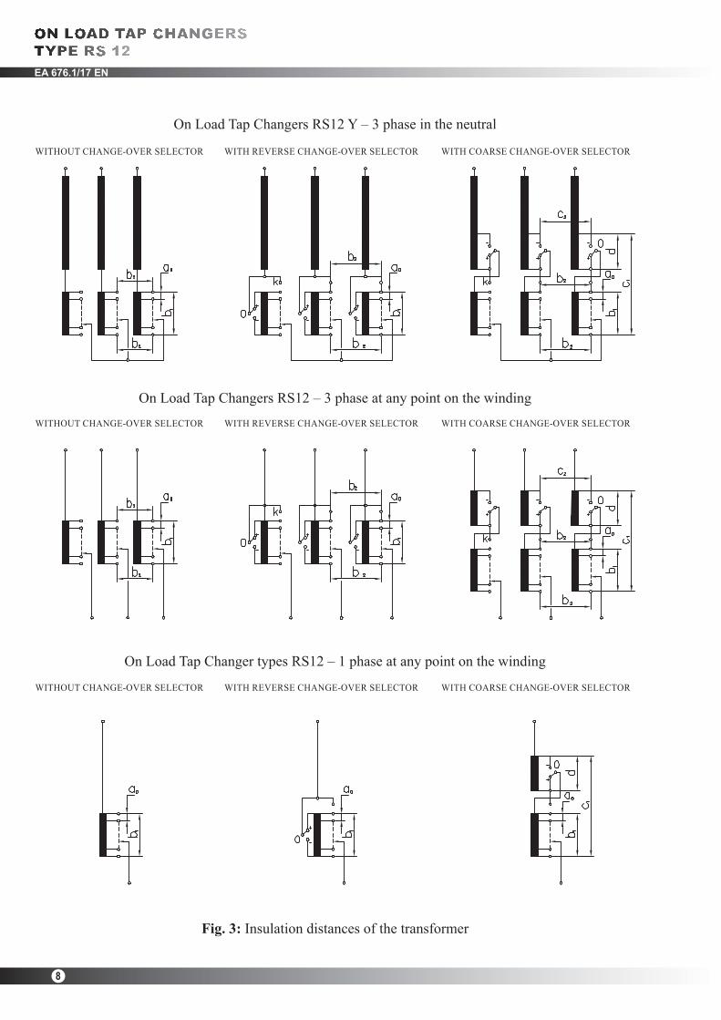
1.4. Insulation levelThe insulation level of the OLTC is determined by a number of withstand voltage values.The rated withstand voltage values to earth are given in Table 1. These voltages are determined by national and international standards.Theinternalinsulationisdimensioneddependingonthevoltagesdefinedbythetransformerwindingtapstothedifferentpartsoftheselector,change-overselectorandthediverterswitch.Fig. 3 shows the main connection diagrams and the typical insulation distances to them. ThewithstandvoltagevaluesfromthedifferentinsulationdistancesaregiveninTable3.ForacorrectOLTC selection, these voltage values should correspond to the voltage values that occur during the lightning impulse test, the induced voltage test and the power frequency voltage test of the transformer. The least favorable position of the OLTC should be taken into account. The insulation to earth and the tap selector insulation size are not mutually connected and can be selectedinaccordancewiththespecificrequirements.
6
100000
200000
300000
400000
500000
600000
00 0.5 0.6 0.7 0.8 Iu/Ium
RS12 400A
0.9 1
RS12 200A
n
7
Table 3: Withstand voltages
Insulation distance Test voltage,kV
OLTC TYPERS-12 Y 200RS-12 Y 400
RS-12 D 200RS-12 D 400
RS-12 I 200RS-12 I 400
a0 1,2/50 µs 120 120 120AC test voltage 40 40 40
b1
10 contacts 1,2/50 µs 210 180 210AC test voltage 60 50 60
12 contacts 1,2/50 µs 210 180 210AC test voltage 60 50 60
14 contacts 1,2/50 µs 190 180 190AC test voltage 55 50 55
b2
41,5 kV 1,2/50 µs 250 250 -AC test voltage 75 110 -
72,5 kV 1,2/50 µs 250 350 -AC test voltage 75 140 -
123 kV 1,2/50 µs 250 - -AC test voltage 75 - -
145 kV 1,2/50 µs - 650 -AC test voltage - 275 -
c1
41,5 kV 1,2/50 µs 340 340 340AC test voltage 100 100 100
72,5 kV 1,2/50 µs 340 340 340AC test voltage 100 100 100
123 kV 1,2/50 µs 340 - 340AC test voltage 100 - 100
145 kV 1,2/50 µs - - -AC test voltage - - -
c2
41,5 kV 1,2/50 µs 320 320 -AC test voltage 110 110 -
72,5 kV 1,2/50 µs 320 350 -AC test voltage 110 140 -
123 kV 1,2/50 µs 320 - -AC test voltage 110 - -
145 kV 1,2/50 µs - - -AC test voltage - - -
d
41,5 kV 1,2/50 µs 280 280 280AC test voltage 70 70 70
72,5 kV 1,2/50 µs 280 280 280AC test voltage 70 70 70
123 kV 1,2/50 µs 280 - 280AC test voltage 70 - 70
145 kV 1,2/50 µs - - -AC test voltage - - -
f
41,5 kV 1,2/50 µs 250 250 250AC test voltage 110 110 110
72,5 kV 1,2/50 µs 350 350 350AC test voltage 140 140 140
123 kV 1,2/50 µs 550 - 550AC test voltage 230 - 230
145 kV 1,2/50 µs - 650 -AC test voltage - 275 -
Note:Fordesignatedinsulationdistances–seediagramsfromfig.3
EA 676.1/17 EN
8
Fig. 3: Insulation distances of the transformer
On Load Tap Changer types RS12 – 1 phase at any point on the winding
WITHOUT CHANGE-OVER SELECTOR
WITHOUT CHANGE-OVER SELECTOR
WITHOUT CHANGE-OVER SELECTOR
WITH REVERSE CHANGE-OVER SELECTOR
WITH REVERSE CHANGE-OVER SELECTOR
WITH REVERSE CHANGE-OVER SELECTOR
WITH COARSE CHANGE-OVER SELECTOR
WITH COARSE CHANGE-OVER SELECTOR
WITH COARSE CHANGE-OVER SELECTOR
On Load Tap Changers RS12 Y – 3 phase in the neutral
On Load Tap Changers RS12 – 3 phase at any point on the winding

9
1) For the rest of the dimensions see appendices
2. Review of the RS 12 types2.1. Main dimensions
Fig. 4: RS 12 – Y/ ∆–200,400
Fig. 6: RS 12 – I – 200, 400
Fig. 5: RS 12 – Y/ ∆–200,400
Fig. 7: RS 12 – I – 200, 400
Table 4: RS 12 – Y/ ∆–200,400
Table 5: RS 12 – I – 200, 400
WITHOUT CHANGE-OVER SELECTOR
WITHOUT CHANGE-OVER SELECTOR
WITH REVERSE/COARSE CHANGE-OVER SELECTOR
WITH REVERSE/COARSE CHANGE-OVER SELECTOR

EA 676.1/17 EN
10 10 0 12 12 0 14 14 0
9 steps 11 steps 13 steps
10 19 1G 12 23 1G 14 27 1G
+9 steps +11 steps +13 steps
10 19 3G 12 23 3G 14 27 3G
+8 steps +10 steps +12 steps
+6 steps+4 steps +5 steps
10 09 1G 12 11 1G 14 13 1G
10
Fig. 8: Basic connection diagrams
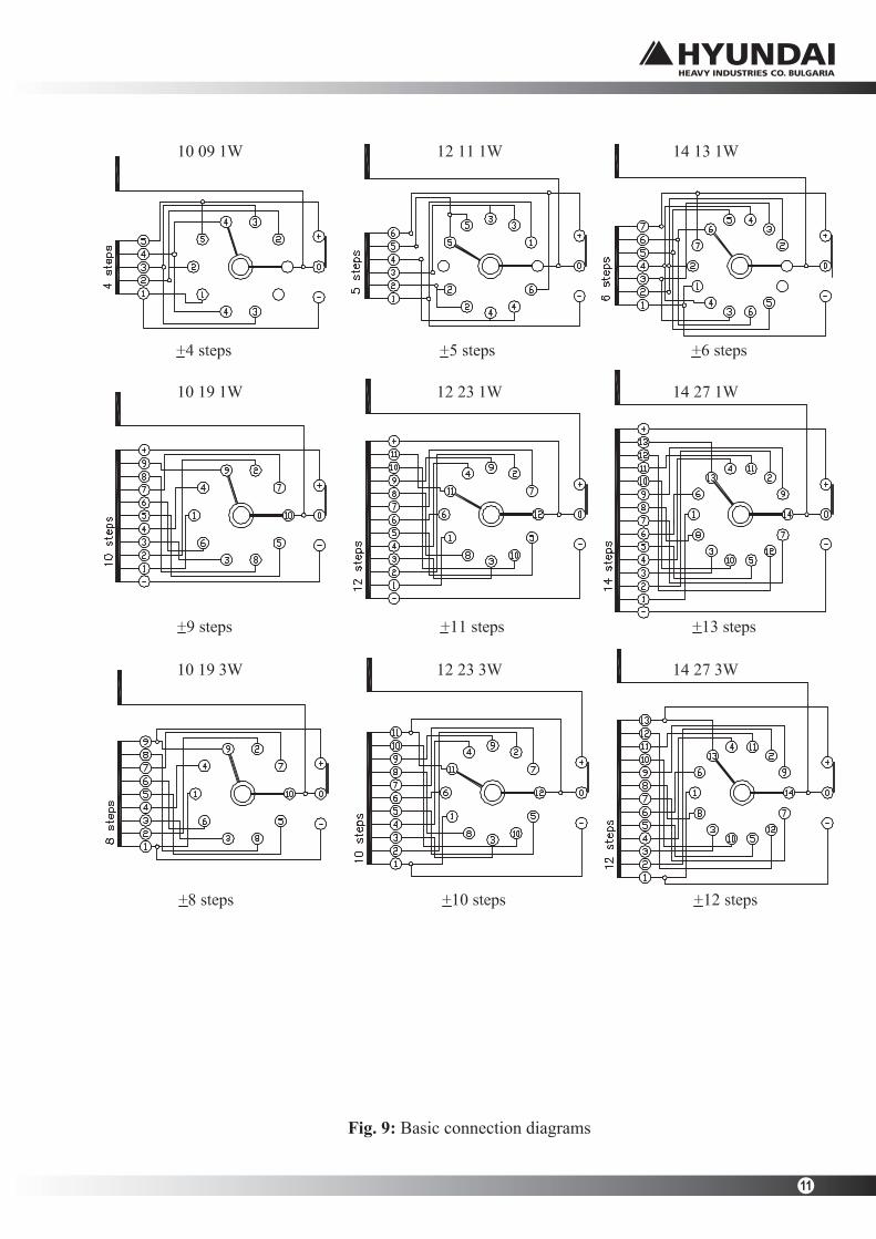
2.2. Basic connection diagrams.
2.2.1. Designation and range of regulation.
Basic diagrams with contacts designation, corresponding to the designations in the overall drawings areshownonfigures8and9.
11
Fig. 9: Basic connection diagrams
EA 676.1/17 EN
12
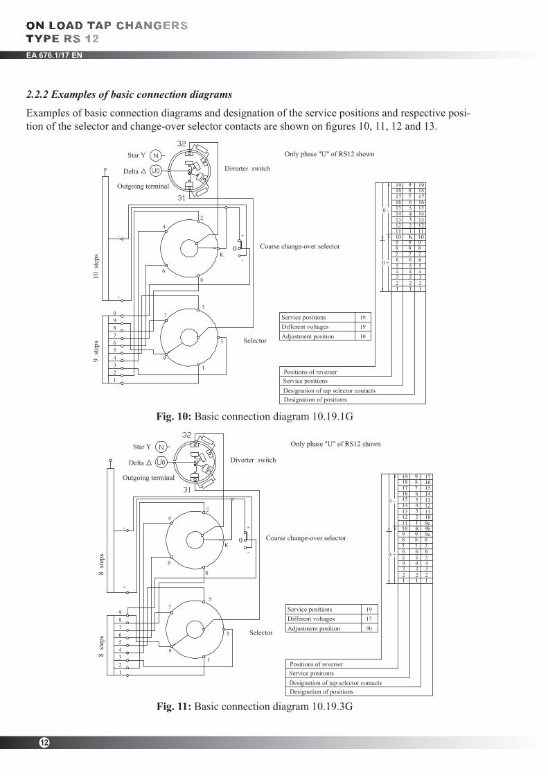
Fig. 11: Basic connection diagram 10.19.3G
Fig. 10: Basic connection diagram 10.19.1G
2.2.2 Examples of basic connection diagrams
Examples of basic connection diagrams and designation of the service positions and respective posi-tionoftheselectorandchange-overselectorcontactsareshownonfigures10,11,12and13.
13
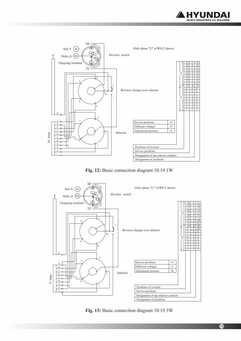
Fig. 12: Basic connection diagram 10.19.1W
Fig. 13: Basic connection diagram 10.19.3W
EA 676/16 ENG
14
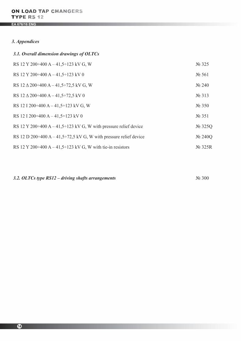
3. Appendices
3.1. Overall dimension drawings of OLTCs
RS12Υ200÷400A–41,5÷123kVG,W №325
RS12Υ200÷400A–41,5÷123kV0 №561
RS12Δ200÷400A–41,5÷72,5kVG,W №240
RS12Δ200÷400A–41,5÷72,5kV0 №313
RS 12 I 200÷400 A – 41,5÷123 kV G, W №350
RS 12 I 200÷400 A – 41,5÷123 kV 0 №351
RS 12 Y 200÷400 A – 41,5÷123 kV G, W with pressure relief device №325Q
RS 12 D 200÷400 A – 41,5÷72,5 kV G, W with pressure relief device №240Q
RS 12 Y 200÷400 A – 41,5÷123 kV G, W with tie-in resistors №325R
3.2. OLTCs type RS12 – driving shafts arrangements №300
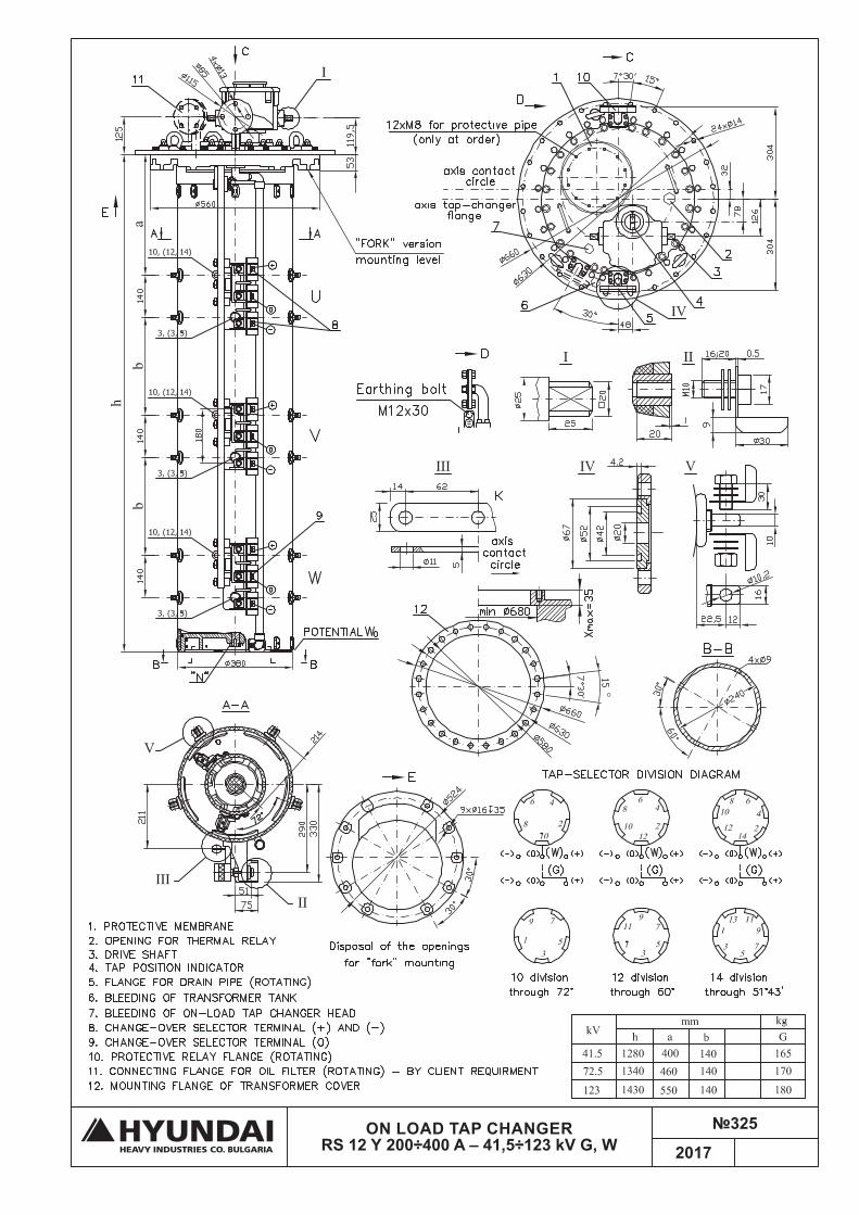
ON LOAD TAP CHANGER RS 12 Υ 200÷400 A – 41,5÷123 kV G, W
№325
2017

ON LOAD TAP CHANGER RS 12 Υ 200÷400 A – 41,5÷123 kV 0
№561
2017
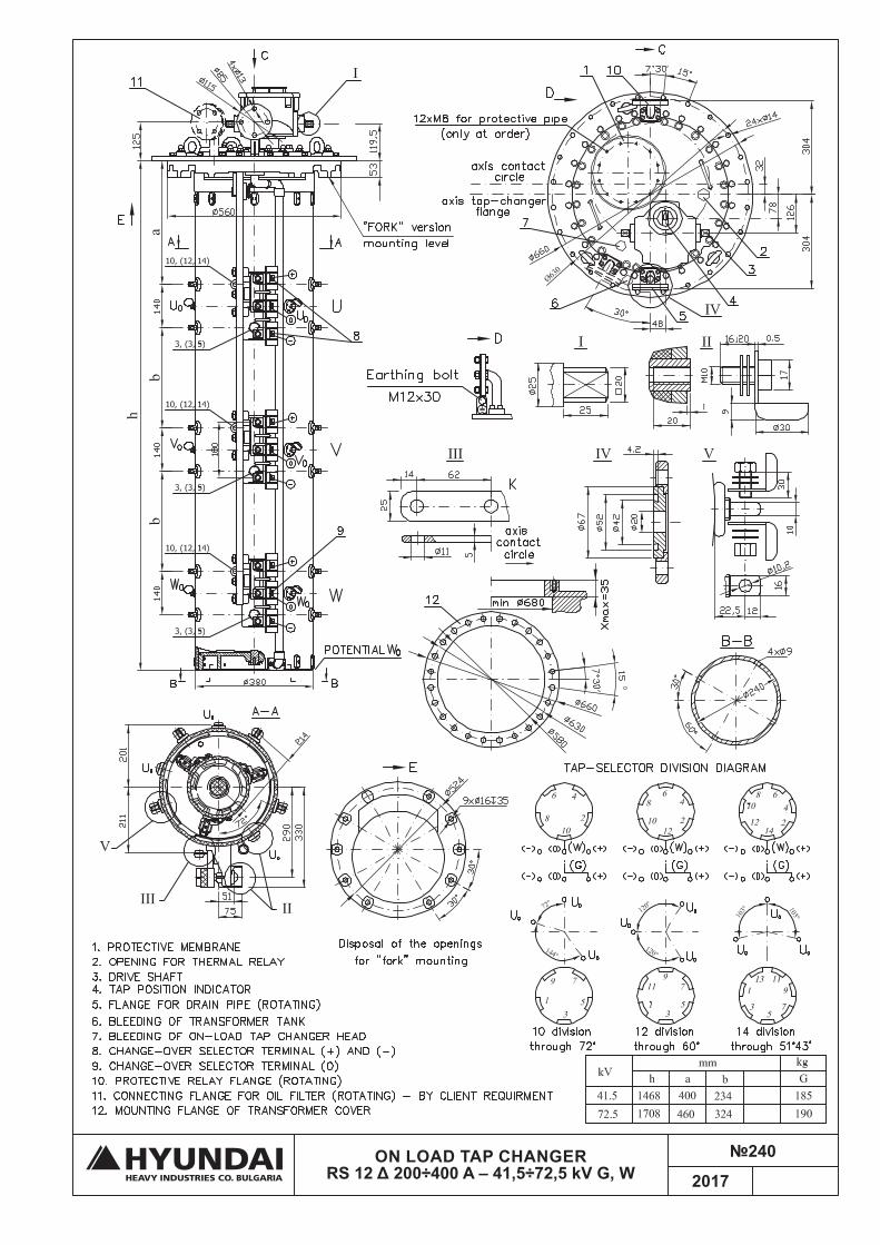
ON LOAD TAP CHANGER RS 12 Δ 200÷400 A – 41,5÷72,5 kV G, W
№240
2017

ON LOAD TAP CHANGER RS 12 Δ 200÷400 A – 41,5÷72,5 kV 0
№313
2017
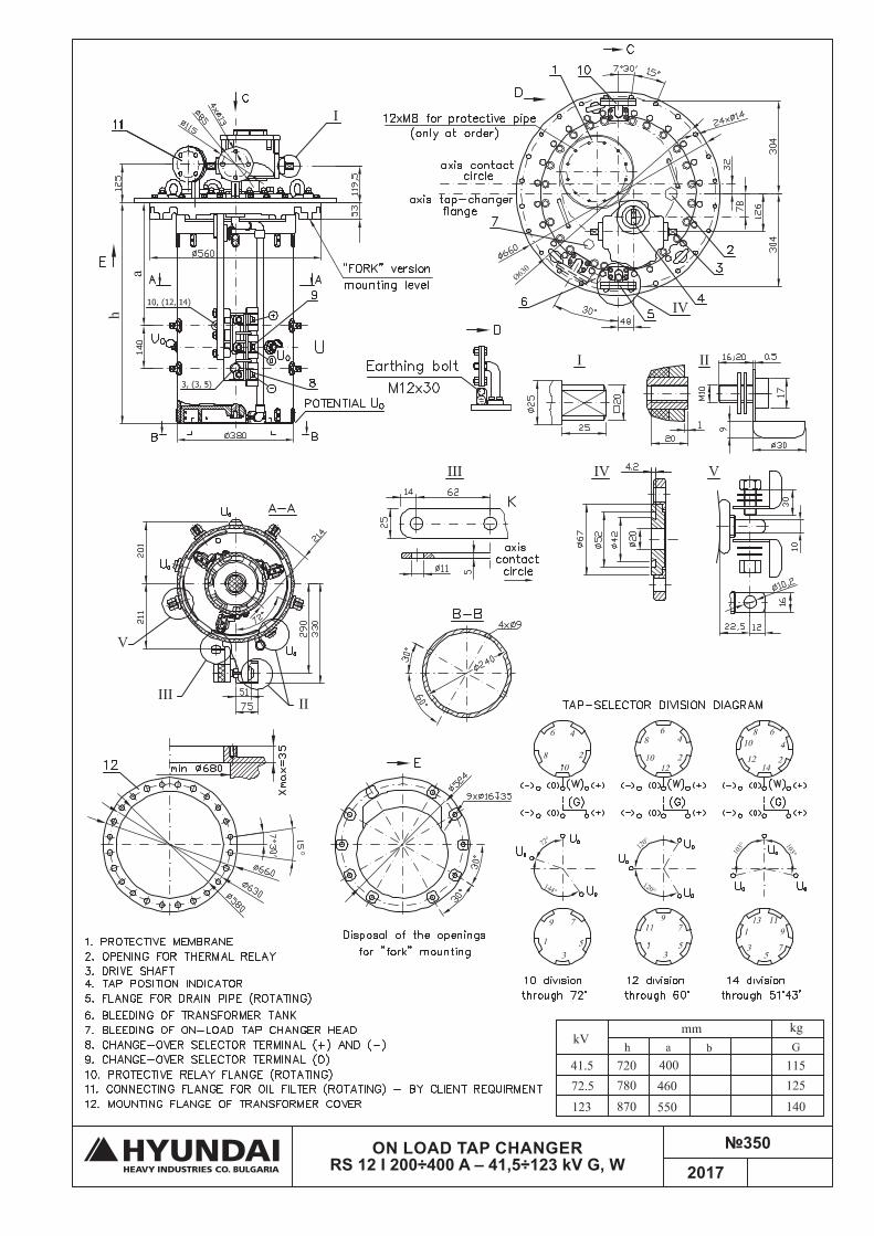
ON LOAD TAP CHANGER RS 12 I 200÷400 A – 41,5÷123 kV G, W
№350
2017
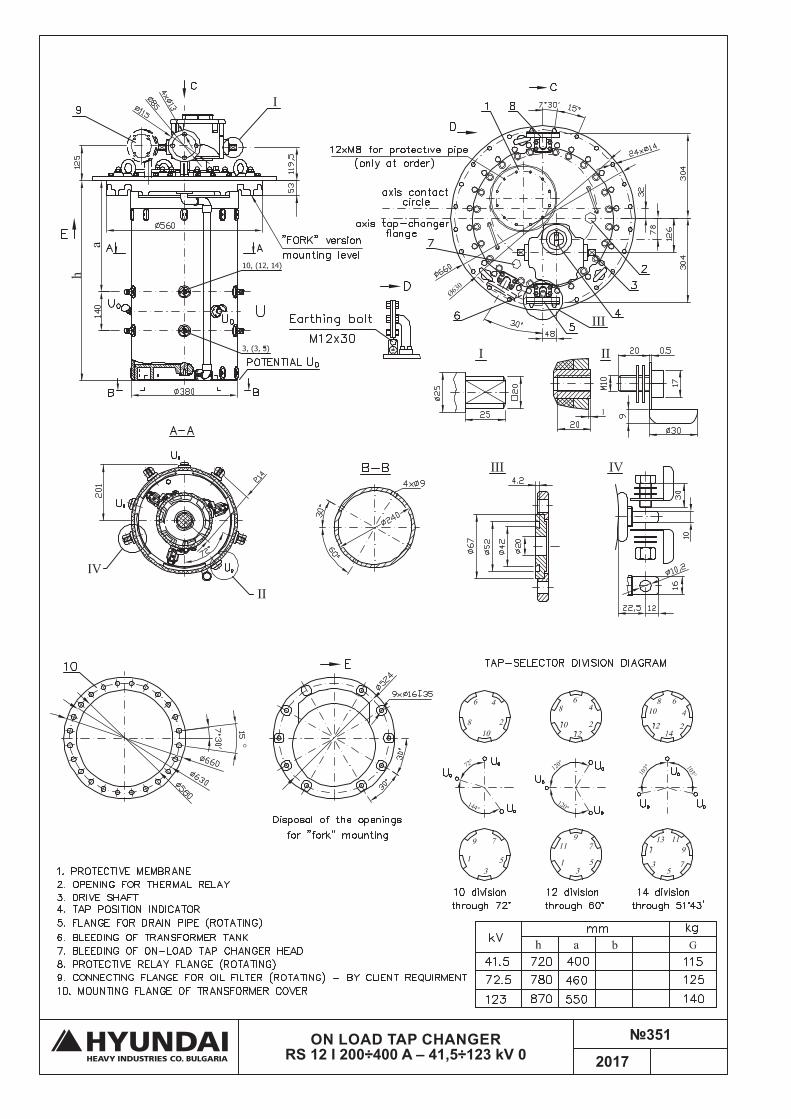
ON LOAD TAP CHANGER RS 12 I 200÷400 A – 41,5÷123 kV 0
№351
2017
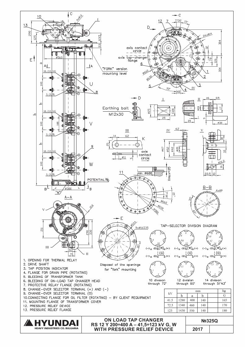
ON LOAD TAP CHANGER RS 12 Y 200÷400 A – 41,5÷123 kV G, W
WITH PRESSURE RELIEF DEVICE
№325Q
2017
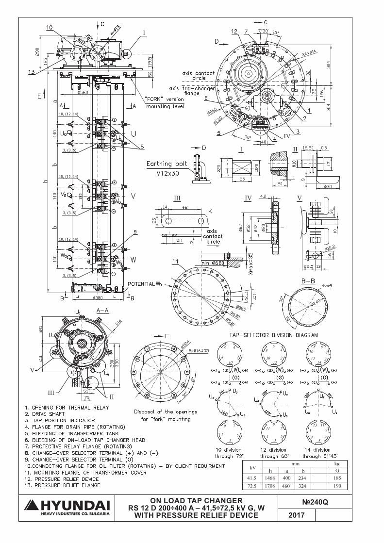
ON LOAD TAP CHANGER RS 12 D 200÷400 A – 41,5÷72,5 kV G, W
WITH PRESSURE RELIEF DEVICE
№240Q
2017

ON LOAD TAP CHANGER RS 12 Y 200÷400 A – 41,5÷123 kV G, W
WITH TIE-IN RESISTORS
№325R
2017

DRIVING SHAFTS ARRANGEMENT for OLTC type RS12
№300
2017