Embed Size (px)
Citation preview
~.
...
f!'
(
Welded Continuous Frames and Their Components
Interim~eportNo~ 33
COM MENTARY
ONPLASTIC DESIGN
(Theoretical .Considerati.ons"~ExperimentalVerification-Design Guides)
This w~rk has been carried out as apart of an investigation sponsored jointlyby the Welding Research Council and theDepartment of the Navy with funds furnishedby\the following:
.American Institute of Steel ConstructionAmerican rronand Steel InstituteI~stit~te of Research, Lehigh UniversityColumn Research Council (Advisory)'Office of Naval Research (Cont~act no 61003)Bureau 6f ShipsBureau of.Yards· and Docks
Project Staff : L. S. Beedle, G. C. Driscoll,J. w. Fisher, T. V. Galambos,R. L. Ketter, T. Kusuda, L. W. Lu,J. A. San~os, B. Thurlimann
Fritz Engineering LaboratoryDepartment of Civil Engineering and Mechanics
Lehigh UniversityBethlehem, Pennsylvania
Fritz Laboratory Report No. 205 ..53Dr,aft 3, February~'1958-
•
205,53
TA. B L E
SYNOPSIS
1, INTROIJUCTION
.,::..1.1 Objective1,2 Structural Design1,3 . Plas tic- Des-ign
2. BASIC PRINCIP~ES
o F CON TEN T S
Page
i
1.1
2.1
2.1·2,.2
Behavior of Material and Elements.,
Plastic Tp.eorya. Conditionsb. Introduction to Methoos of Analysis
- I
o3. ANALYSIS AND DESIGN
3.1 Assumptions3.2 Statical Method3.3 Mechanism-Method,
4 ... 'GENERAL PROVISIONS
4.1 Introduction4.2 Types of Construction4.3 Mat.erial4,4 Structural Ductility4.5 Yield Stress Level4.6 Plastic Moment4.7 Loads and Forces4.8 Load Factor
3.1
..
.'
5. VERIFICATION OF P~~TIC THEORY
5.1 ~asic Concepts1, Ductility of ~teel
2. The plastic moment and the plastic hinge3. ,Redistribution of moment
5.2 Continuous Beams5.3 Frame Tests
5.1
..
•
205,:53
o 6, SECONDARY DESIGN .CONSIDERATIONS
6,1 .Shear force6,2 Local buckling6,~ Lateral buckling6,4 Axial force -- Column buckling
ao Simpleb. Framed
6,5 Repeated· Loading-- .
() 7. CONNECTIONS
() 8, MISCELLANEOUS REQUIRilliENTS
801 Deflections
o 9. SELECTED REFERENCES
10. ~OMF:NCI4TURE AND TERMINOLOGY.
1, Definitions2-, Nomenclature
11 . APPEND lXES
1, Plastic Modulus Table
6,1
7.1
8.1
9.1
10.1
205,5.3
This report aims to JL+stify and to document the applicability of
plasti.c analysls t.o design in structural steel, Theoretical consid
erati.ons involved in th,e plastic theory and in certain secondary
design problems are given, Experimental verificationisprovi.ded,
.Approximations in the form of "desi.gn guides" are suggested,
i
A separate and comparison report will illust.rate the procedures
of the plastic method with specific design examples, and will supply
information to supplement. clauses in a specification for plastic design,
..
205.53(1.1)
101 Objective
10 INTRODUCTION
1.1
•
The evaluation of a considerable amount of res~arch .work. has dem-
onstrated the applicability of plastic analysis to structural design.
The justification for plastic design is that it results in an over-all
balanced design with known factor of safety, it holds-promise for a
more economical use of material, and compared with elastic methods it
is a simpler design office technique for the types of construction
later described.
In considering the practical application of plastic design, it is
considered that three documents eventp~lly will be required.
(1) A commentary g1.v1.ng the ba~kground of the~iy and tests,together with such design approximations as areappropriate.
(2) A manual of plastic design, containing design examples.
(3) .A specification
It is the purpose of this report to meet the need of item (1)
above. It will constitute a justification and a documentation of the
applicability of plastic analysis to design in structural steel.
Theoretical considerations involved in the plastic theory and in
certain secondary design problems are given. Experimental verification
is given, and approximations in the form of "design guides" are suggested .
205053(L2)
L2
-~
..
Work on the manual of design examples (Item 2) is underway in the
offi.ces of the American Institute of Steel Construction, A specift-
cation (Item 3) would followo As a means of implementing the use of
plastic design, a paragraph (or paragraphs) could be added to present
specifications allowing the designer to proportion certain structures
according to the plastic method of structural analysis so long as he
demonstrates that he conforms to the recommended procedures,An alter~
nate specification might then be developed to .. which specific reference
would be made thereaftero
1,2 Structural Design
In selecting the members for a steel frame structure it is necessary
first to make a general analysis of structural strengthand,second, to
examine certain detai~s (usually covered by codes or specifications) to
assure that -local failure does not occur before the structure performs
its intended function,
The structural strength or design load of a steel frame may be
determined or controlled by a number of factors, anyone of which.may
actually constitute a "Limit of Structural Usefulness":"
,1. Attainment of a hypothetical yield-point stress(ignoring stress concen~rations) .
. ,20 Attainment of maximum (plastic) strength
3, Large deflections
40 Instability
50 Brittle fracture
6, Fatigue (endurance limit)
"
205,53(1.3) 1.3
•
Item 1 in conjunction with It~ms 4 and 6 has, for many years, been the
basis for structural design, , which uses the "working stress" concept"
, Certain provisions also are included in standard specificat,ions which~ \
are intended to insure that the capacity is not limited by~ne of ,the
other "limit.s of structural usefulness".
1.3 Plastic Design
Strictly speaking, a design based on anyone of the six factors
listed above could be referred to as a "Limit Design", although the
term usually has been applied to determination of maximum strength
according to Items 2 and 4, ,"PLASTIC DESIGN", as an aspect of limit
design, embraces primarily Item 2 (attainment of maximum plastic strength)
as applied to continuous beams and frames. It is, first, a "des;'ign on
the basis of the maximum load the structure will carry, as determined
from an analysis of strength in the plastic range (1. eo, plastic
analysis), Secondly, it involves the consideration -- by rules or
formulas -- of certain "limitations", "restrictions", or "modifications",
without which the structure might not attain this theoretical maximumI
strength, ,Many of these limitations are present in conventional design,
while others are inherently associated with plastic behavior, The unique
feature of plastic design is that the ultimate load rather than the Yi.eld,
stress is regarded as the design criterion, Whereas elastic design is
performed by assuming working loads and a working unit stress, plastic
design is based on ultimate loads and ultimate (or capacity) moments,
T
2.05.53(1.3) 1.4
•
Maximum load computations for continuous frames are based on the
assumption that IIp las tic hinge moments ll are developed at critical points
in the structure and maintained durIng the subsequent loading, Thus
desi.gn criteria for the'stability of details, which merely guard against
elastic buckli.ng;, require re-examination in plastic design where plastic
buckling must be, controlled, ,Deflection may constitute a second, dei:lign
criterion but is of no greater significance than in other design spec-
ificat:i.ons,
The maximum l~ad determined by plastic analysis may thus be thought
of as an 11ideal ,maximum", as there is the possibility that one or more
factors may operate to make it impossi.ble of attainment, while other
,4 factors will operate to ;l,ncrease this maxi,mum load. However, c~rtainI
"plastic parameters" are now sufficiently substantiated so that design
guides may be suggested in order that engineers can enjoy the advantages
inherent tn the method,
A Hungarian, Gabor Kazinszy, fi.rst applied these'concepts to the
design of some apartment-type buildings in 1914. (1.1) (1.2) Early testfj
were made in Germany by Maier-Leibnit~~(1.3) Van den Broeck, (1~4)
(1.5)" d . k (1'6) H (1..5,1.7) H (1.8) G~eenberg (1.9),Baker, ,Ro er~c, r orIle , eyman", "
P (1.9) S d (1,10) Neal (loll) Winter (1.12)'and Johnston(1.12)rager, ymon s, " ' '" ,
have all ma~e contributions to t~e plastic theory of structures, PlasticI
design is already a part of certain specifications and engineers are
now making use of it.
1
205.53
Chapter 1
L5
L 1 G KAZINSZY, "KiserletekBefalazott Tartokkal" ("Experiments withClamped Girders"), Betonszemle, 2 (4) p 68, (1914),; 2(5) p 83(1-~14); 2 (6) p 101 (1914)',-
L 2 - N J HOFF, Discussion of Ref 1. .12, Welding Journal 33 (i), l4-s(1954).
L3 MAIER-LEIBNlTZ, "Contri.bution to the Problem of Ultimate CarryingCapaci.ty·of'Simple and Cbnti~uous Beams of Structural Steeland T.imber", Die Bautechnik, 1(6) (1927).
,1. 4 J A VANDEN BROEK, Theory of Limit De'sign, John Wiley and Sons,
1948.
L5 J F BAKER, M R HORNE, J HEYMAN, The Steel Skelton, Vol II: Plastic'B~havior and Design, Cambri.dge University Press, Cambridge,Engl.and\, 1956.
... L6 JW RODERICK, I HPHlLLIl?PS,"Carrying Capacity of Simply SupportedMild Steel Beams", Engine,ering Structures, Aca,demic Press, N.Y.19W.,p 9.
1.7 M.R HORNE, "A Moment Distribution Method for the Ana~ysis andDesign of Structures by the ~lastic Theory". Proc. lnst. Civ.Eag-ineers, p 51, April 1954.:
L 8 J HEYMAN, "Plastic Design of ~ortal Frames", Cambridge UniversityPress, Cambridge, England, 1957.
L9 H.J GREENBERG, W PRAGER, ASCE Transactions, VoL 117,1952, P 4470
1. 10 P S SYMONDS, BG NEAL, "Recent Progress in the Plas tic Methodsof Structural Analysis", J. Franklin lnst., 252, 383-407,469.-492 (1951) ,
1.11 B G NEAL, liThe Plastic Methods of Structural Al1alysis", JohnWiley and Sons, New York, 1957.
,'\\ .I .
I
L12
L13
G WINTER, "Trends in Steel Design and Research", BuildingResearch Congress (1951) Divl, fart II, pp 81-88.
B G\JOHNSTON, C H YANG, L S BEEDLE, "An Evaluation of PlasticAnalysis as Applied to Structural Design", Welding Journal,32(5), 224-s (t953).
205,53(2,1)
20 BAS I.e
2,1
•
2.1 Behavior of Material and Structural Elements
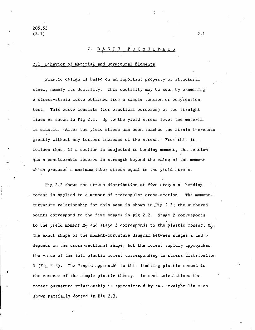
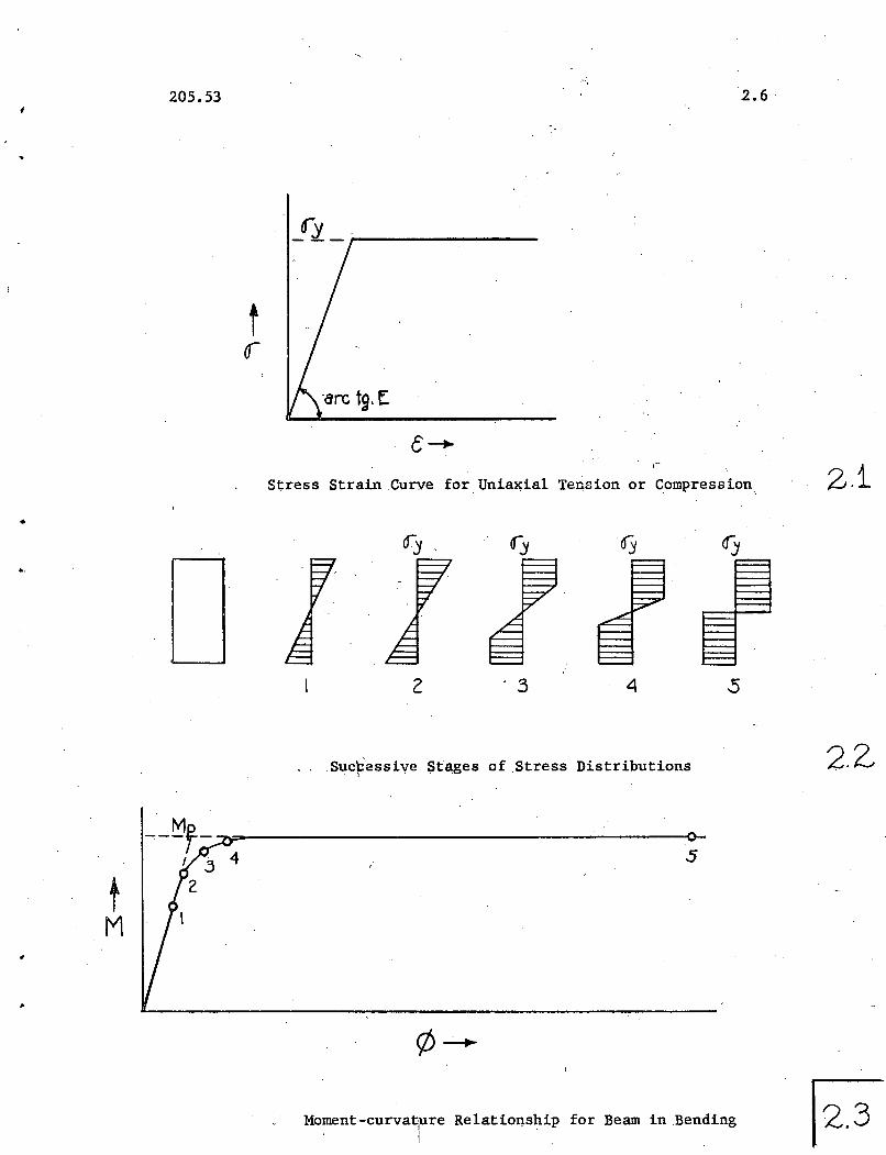
Plastic design is based on an important pr.operty of structural
steel, namely its ductility. This ductility may be seen by examining
a stress-strain curve obtaine.d from a simple tension or compression
test. This curve consists (for practical purposes) of two straight
lines as shown in Fig 2.1, Up to\ the yield stress level the material
is elastic, After the yield stress has been reached the strain increases
greatly without any further increase of the stress;,' From this it
follows that, if a section is subjected to bending moment, the section
has a consider'able reserve in strength beyond the val~.EL..9f the moment
which produces a maximum fiber stress equal to the yield stress.
Fig 2.2 shows the stress distribution at five stages as bending
moment is applied to a member of rectangular cross-section. The moment-
curvature relationship for this beam is shown in fig 2,3; the numbered
points correspond to the five stages in Fig 2,2, Stage 2 corresponds
to the yield moment My and stage 5 corresponds to the plastic moment, Mp '
The exact shape of the moment-curvature diagram between stages 2 and .5
depends on the cross-sectional shape, but the moment rapidly approaches
the value of the full plastic moment corresponding to stress distribution
5 (Fig 2.2). The " rap id approach" to this limiting plastic moment is
the essence of the simple plastic theory, In most calculations the
moment-Cllrvature relationship is approximated by two straight lines as
shown partially dotted in Fig 2,3,
1 205.53(2.2)
The process of successive yielding of fibers as bending moment is
incr;eased (Stage 2. to Stage 5 of Fig 2.2) i.s calledplastification of
the cross section. The plastic hinge thus formed permits redistribution
of moments in statically indeterminate frames. At the secti.on{s) where
yielding occurs, relatively large rotations are possible withoui a s1g-
nificant increase or decrease of moments; in other words, "plastic hinges"
develop. Thus, further increases of the loads are carried by other
parts of the structure, until a sufficient number of plasti.c hinges are
formed so that the structure at this point starts to behave as a mechanism.
Thereafter deflections would increase rap~dly while the loads remained
practi~ally constant. In other words, the ul timate load has been reached.
In summary, a structure will r~ach its ultimate load as determined
by simple plastic theory only if the sections or connections where
plastic hinges are to form attain the predicted moment and subsequently
are able to undergo sufficiently large rotations. An excepti.on, of
course, is the plastic hinge which forms last, for which no inelastic
rotation is required after the plastic moment has been reached.
2.2 Plastic Theory
(a) Condi.tions
In the elastic analysis of an indeterminate structure one mus,t
consider three conditions:
1. ,Continuity - the deflected shape is assumed to be a continuous curve, and thus "continuity equations" may beformulated.
2. Eq}.lili.brium - Summation of forces (an~ moments) is equalto zero.
3. Limiting Stress (or moment) - In elastic analysis theli.miting moment is the yield moment.
205.53(2.2) 2.3
'>,
..
In plastic analysis three similar conditions (or modifications
thereof) must be considered~ .With regard to continuity, the si.tuation
is just the reverse: theoretically plastic hinges interrupt continuity,
so the requirement is that' sufficient plastic hinges form to allow
the structure (or part of it) to deform as a mechanism. This could
be termed a mechanism condition. . The equli.librium condition is the
same as in elastic analysis. Instead of initial yield, the limit of
usefulness is the attainment of plastic hinge moments, not only at one
cross secti.on but at each of the critical sections; this will be termed
a plas~ic moment condition. A corollary to this is the obvious fact
that moments in excess of the plastic bending strength could noi: be
resisted. The three conditions that must be satisfied in plastic analysis
are, therefore,
1. Mechanism Condition2. EquilibriumGondition.3. Plastic Moment Condition
(b) Introduction to Methods of Analysis
When all three of the above necessary conditions are satisfied
(Equilibrium, ~lastic Moment, and Mechanism), then the resulting
analysis for ultimate load is correct because two basic theorems are
satisfied. These ar~ the "Lower Bound" and the "Upper Bound" Theorems
which are as follows:
Lower Bound Theor.em: A load corresponding to an equilibrium moment
diagram in .whichM~ .Mp and witha~bitrarily assumed values for the
redundants is smaller than or at best equal to the true ultimate load.
!
2.. ~5. 53d.2) 2.4
Upper Bound Theorem: .A loq.d computed on the basis of an assumed
mecp.anism .will always be greater than or at .best equal to the ultimate
load .
. These theorems, proved in.Ref 2.1, have been illustrated a,ndI
discussed in Ref 2.2.
There are numerous methods by which a continuous steel structure
- -may be analyzed for maximum strength. In the semi-graphical ("statical"
or "equilibrium") method, an equilibrium moment diagram is drawn such
that tQe moment is nowhere greater than Mp. It thus automatically
satisfies the lower bound theorem. The resulting ultimate load is
correct only if sufficient plastic hinges were assumed to cre~te a
mechanism (thus satisfying the upper bound theorem). In the mechanism
rp.ethod a mechanism is assumed and the resulting virtual work ?quations
are solved for ultimate load. This value is correct only if the plastic f
moment condition is also satisfied.
Other methods of analysis are available and still others may be
developed in the future. A specification need not direct that any
particular one of these methqds be used, but it should call for an
.analysis giving an accurate measure of maximum strength .
205.53
REF E RE N C E S- - - - - - .- - ,- ,-Chapter 2
2.1 HJ GREENBERG, W PRAEGER, llLimit Design of ,Beams and Frames",ASCE Transacti6ns, ~ 117, p 447, 1952.
2.2 L S BEEDLE, R L KETTER, B THURLIMANN, llPlasticDesi.gn inStructural Steelll , Lehigh University-AISC publications,September 195.5.
2.5
•
205.53
t0-
2.6 '
Stress Strain Curve for Uniaxial Tension or Compression, 2.i
.,
2 '3 4 5
..
tM
Suc~essive Stages of ,Stress Distributions
5
Mo~ent-curvalre Relatiof!.ship for Beam in Bending
2.Z
• 205.53
3. .A N A L Y SIS .--'
3.1
•
When completed, this chapter will first cont~in.a detailed listing/
of the important assumptions that are a part of/the simple plastic
theory. A simple example will then be given of the use of the STATICAL
method of analysis and a second example will illustr;ate the MECaANISM
.meth()d.
It is not planned that this chapter will give complete design
information. That is the purpose of other documents, in particular
the AISC Manual, "Plastic Design in .Stee1". The examples will only
serve to illustrate the basic principles discussed in the previous
chapter •
•
•
205.53(4.2)
4. G E N ER ALP R 0 V I S ION S
4.1 Introduction
This chapter will discuss some of the basic conditions that
4.1
should be satisfied before a plastic design procedure may be set up.
This includes questions regarding types of construction, materials,
structural ductility (avoidance of brittle failure), the yield stress
level to be used, the plastic moment, the loads and forces that
would be considered as applied to the structure, and the load factor.
The particular "provision" will be given first, .followed, by"
pertinent discussion.
4.2 Types ofCpnstruction
The following types of construction aresuitable for plastic design:
(a) Continuous Beams(b) One and two-story, single- and'
multi-span continuous typebuilding frames
(c) Multi-story tier buildings withsidesway prevented by walls and/ordiagonal bracing.
(d) Structures required to absorbdynamic load (bomb blast, etc.)
Plastic design is not recommended as a substitute for elastic
design for s'tructures that are essentially pin-connected. It is
intended for structures which depend upon continuity for their
ability to carry the computed ultimate load.
205.53(4.4 )
The necessary continui.ty may be achieved by welding, riveting
4.2
•
or bolting. The background and justi.fic.ation .for desi9p. gui.des for
the use ot such connecting devices is discussed else\vhere in this
report (See Chapter 7).
Material with the characteristi.cs of ASTMA7 steel for bridges and buildings should beusep-,with modifications, when needed, to insure.weldabili.ty and ductility at lO\vest-expected.·service temperature.
It is not the intent to specify anyone steel, but to indicate that
the important property that is required of a material i.s ductility.
J1any of the high strength steels exhibit stress-strain characteristics
similar to those of structural grade steel except with a higher yield
stress level. It is reasonable to expect that plastic design may be
appli.ed to structures i.nwhich such steels are used, providing they
meet.design guides similai to those suggested in this report, btit
appropriate to the particular material .
. 4.4 StructuraL Ductility
Fabrication processes should bE: such as tore\:ain ductility. She.ared edges and pupchedholes in tension flanges should not be permitted.S~b-punched and reamed holes for connecting,deviceswould be satisfactory if the reaming removes thecold-worked material.
In design, triaxial states ~f tensile stressset up by geometri.cal restrai.nts should be avoided.
This provision together with Art 4.3 assures that brittle failure
wi.ll not prevent the formation of a plastic hinge. The assumption of
ductility is an equally important aspect of elastic design and numerous
design .asstimptions rel.y upon it.
For
..
•
•
205.53(4,5)
In plastiG design the engineer sqould be guided by the ;same
principles that govern the proper design of an all-welded structure.I .
designed by the <;>ldermethods, since ductility is of equal importance
to both. Thus the proper material must be specifled to meet the
appropriate service con~it.i.ons, t.he fabricat.iqn and workmanship
must meet. high st.andards, and design details should be such t.hat the
mat.erial'is as free to deform as possible. (4,3)
.With respect to fabrication, due to the severe cold working
involved, punched holes and pheared edges should not be permitted
in parts that might be subjected to the yield stress in t.ension ~t
ulti.mat.e load. J?unched holes ~ould be permitted if followed by
sufficient. reaming t.o remove the cold-worked material, This limitation
is not as severe as migbt seem to be the case; if punched hol~s are
requi.red for erection, t hey can often be located i.n regions that
would not be subject to large t.ensile forces (for example, near t.he web
center or, in tier buildings, on the bottom flange at the ends of
beams.) In .Ref4, 5 the effe.ct of various edge conditions on to.e.
brittle failure of steel has been studied.
4,5 Yield Stress Level
ASTM A-7 steel, lN.ormal stress, ey= 33.0 ksi 1
L Shear stress, 1y = 19.0 ksi
----------A yield stress level of 33.0 ksi. corresponds to the minimum
yield point permitted i.n. a mill-type acceptance test ofA-7 steel,
It is not ~or that reason, however, that it is suggested as a
205.53(4.5)
4.4
•
reasonable value to be used in the subsequent·computation of the plastic
moment. Use of thi.s quant.ity is justifi.ed because it is very close to
the average basic yield stress level of this same material un,der SllS-,
tai.ned loading.
..The mill-type test differs from the test conducted in the laboratory
because of a number of factors, one of the most important of which ~s
strain rate .. An extensive investigation into the yield stress level
has been conducted(401)using.ast.he t.est specimen a complete cross-
sectionot' a rolled WF shape .. The loading. was carried out in a manner
that simulates "stat.ic" loadin.g .. By such a test. procedure it was
possible to include such effects as di.fferences in.web and flange
strength, strain rate, and si,.ze, since representative cross sections
from the very smallest to the. largest rolled shapes were included in\
the program.
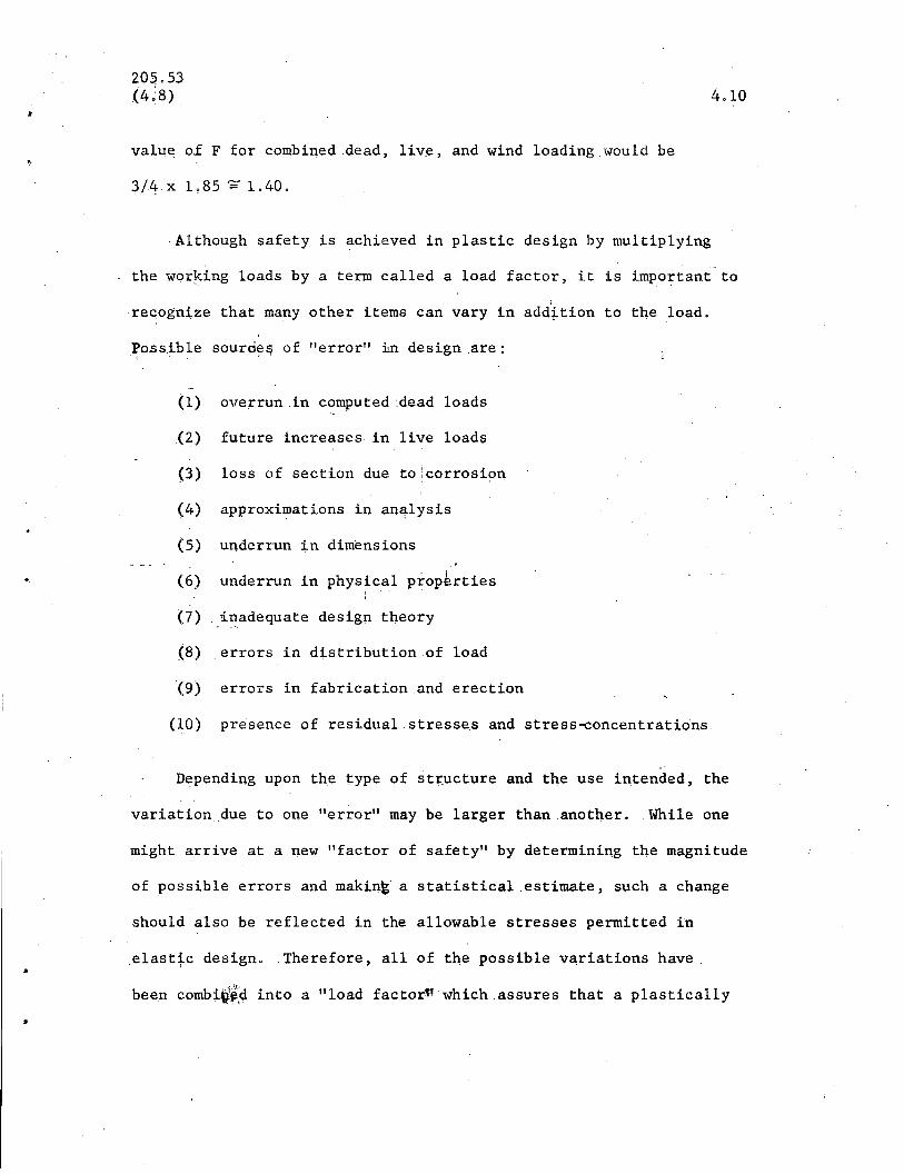
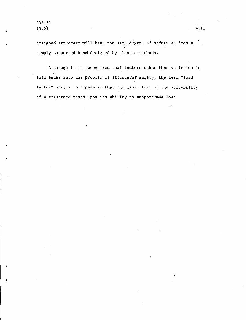
The investlgati.on showed that. the most probable value of the
yield stress level is 34.1 ksi, with variations ranging from 24.6 ksi
to 43.0 ksi. (According to the usual acceptance-type test, the most
probable value of the yield stress level would be 4206 ksi.) .. Fig 4.1
shows the histogram of the ratio of yield stress level according to a
stub column test as compared with a mill-type acceptance tesLFig.
4.2 shows an Haverage" st.ress-strain curve for A-7 steel .
. While 33.0 ksi is t.he minimum yield stress permitted in acceptance
tests, as pointed out above, it represents about the average basic yield
stress level of this materi.aL .Thus the factor of safety includes
J
205 • .53(4.6)
the possibility of variation. below this average value, because the
4~5
•
•
design. is actually based on. .an average., not a minimum. This ·situation
has always existed in the design of simple beams, and therefore
represents no departure from past practice.
If some other material is being considered for an application in
plastic design the proper approach would be to select a representative
series of "stub columns" and test them in a controlled manner,
.4.6 Plastic Moment
~ = OyZ ... (4.1)
0y = yield Atress level
Z = plastic modulus*
.As pointed out in Article 2.1, the formation of plastic hinges
.-is of basic importance to plastic design. Fig 2.3 shows the charac-
teristic moment-rotation curve of a beam under bending, and the moment
at "st';age\ 5" shown in Figs 2.2 and 2.3 is called the plastic moment.
It is computed according to Eq (4.1).
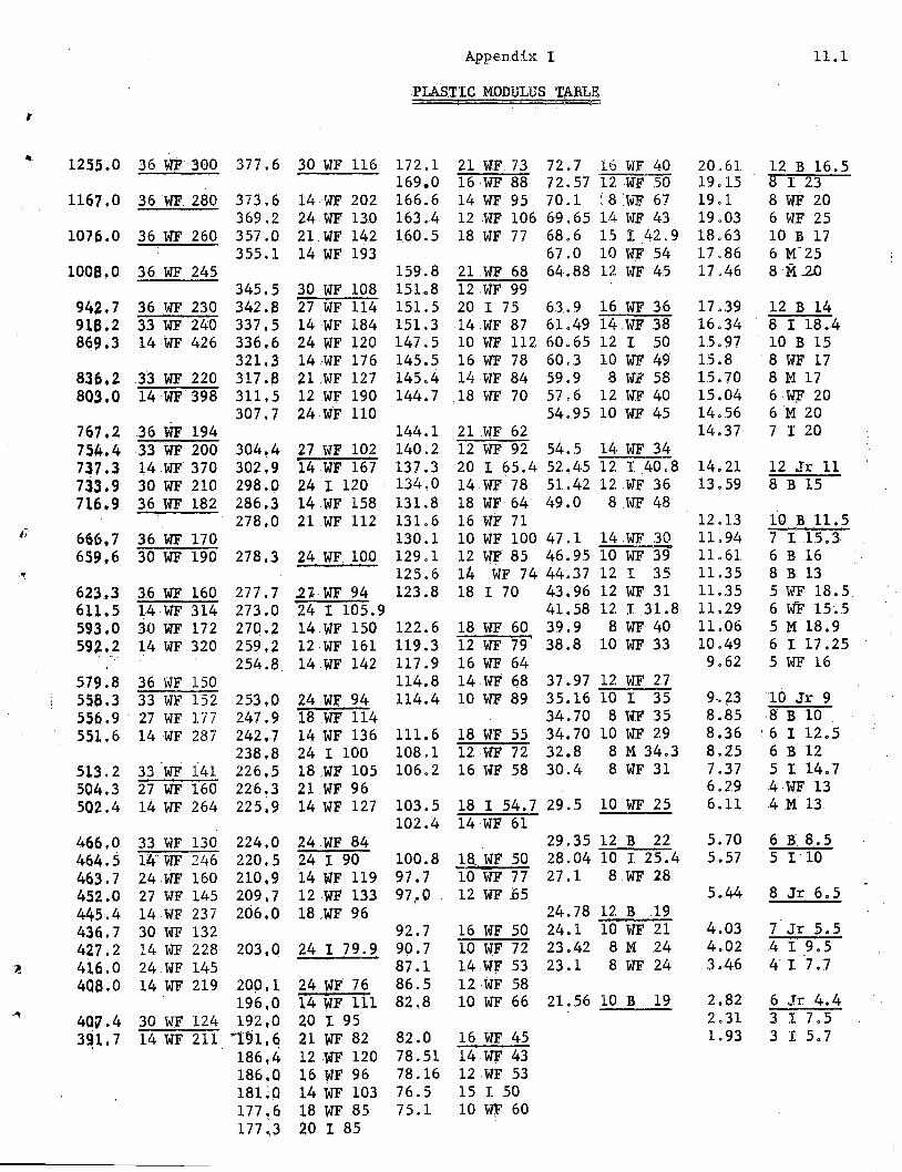
Z, the plastic modulus, is defined as the combined statical
moments about the neutral axis of the cross-sectional areas~"above
and below that axis •. Appendix 1 contains the plastic modulus for
rolled WF shapes and I shapes, arranged as an lIeconomy" table ~
As will be evident in Chapter 5, it is frequently observed in
*See Appendix 1 forWF and I shapes
1
205.53(4.7)
tests that the moment.-deformation behavior is not exactly like that
shown in Fig 2.3 (See Fig 5,4, for example). Because of strain-
\
hardening, the resisting moment is greater th~; the value computed
according to Eq (4.1) (a reserve t.hat i.n some cases wi.ll not be
attained). Further, any theory that would attempt to take this
additional reserve in strength into account would. lead t.o u~due
complications.
4.6
For a material whose characteristics are not similar to A7 steel,
but which exhibits conti.nuous ~_train-hardening, it might be desirable
to arrive at a semi-empirical value for the "plastic hinge" moment •
.Rese~rchwould have to be carri.ed out on the particular material
(including bending tests and tests of indeterminate structures) to
arrive at. a suitable approximat.ion.
4.7 Loads and For~es
The loads and forces to be provided for(allowable load~and forces) should bethose that are 'customary for the part:f",.
icular type of construction..MembeIiG. areselected on the basis of their plasticstrength to resist the most criticalloading condition.
Pu = F Pw . .. (4.2)
F = Load factorPu= Ultimate loadPw= Allowable (working) load
Loading is assumed to be static andproportional.
The use of plastic design does not involve any changes in the
205.-53(4.8)
4.7
. \\
natur.e of the loading on the structur.e .. The structure is designed to
support the same service loads· as at present. .The difference is that
members are selected so that the structure will just support the com-
puted ultimate load, Pu , whereas inelastic design the members are so
selected that a certain critical unit stress will not be exceeded at. .
service load, Pw'
It is assu~ed that the loading is static and proportio~~leven for
the ordinary fluct4ations of load found in buildings. ,For un4sual
conditions, deflection stabili~ywould be investigated. (See l),rt 6.5).
The loading conditio~s that would be investigated (for building
construction) are~
1) Total live load p14S dead load
2)
3)
4.8 Load Factor
Live load plus dead load plus wind orear~hquake acting from the left*
Live toad plus dead load plus wind or'\f. . .
earthquake acting fro~ the left and thenright* in the case oi:unsymmel=rical structures.
,Dead load plus live load, ,F = 1.85
De~d load plus live loadplus wind'orearthquak~F = 1.40
As indicated by Eq (4.2) in Art 4.7, in order to determine the
ultimate loads to be used in plastic design the expected or working,
loads are multiplied by a factor called the "load factor". _Sections
*-~----------r--
In~he case of multi-story buildings,_wind is taken by walls or separatebracing systems.
205053,(408)
are then selected which will just support this factored load o
4.8
The philosophy by which the load factor is selected is as follows:
If the present elastic design of a simply supported beam is satisfactory,
then an indetermi.nate structure should be desiglled with the same;q,..;._i"''''
safety factor against ultimate load. There would certainly be no point~..:~~~-1tR:~.)\,m~~~
in requiring any greater margin of safety simply because th~str4cture
is redundant.
The load factor of a simple beam is equal to the ratio of the
uttimate load, Pu , divided by the .working load, l?w; thus F= P~/Pw.
Ina simple beam the bending.moment varies linearly with the load, or
F = Pu = ~P l1w.w
Substituting the known values for Mp and Mw,
.F = = 33 f20 = 1.65 f .00 (4.3)
The magnitude of the lpad factor is thus dep~ndent upon the shape
factor, a quantity that will vary with different cross-sectional
shapes .. The magnituQe of th~ shape factor is given by
f = .Z/S (404)
,!
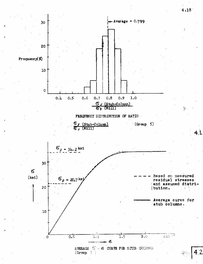
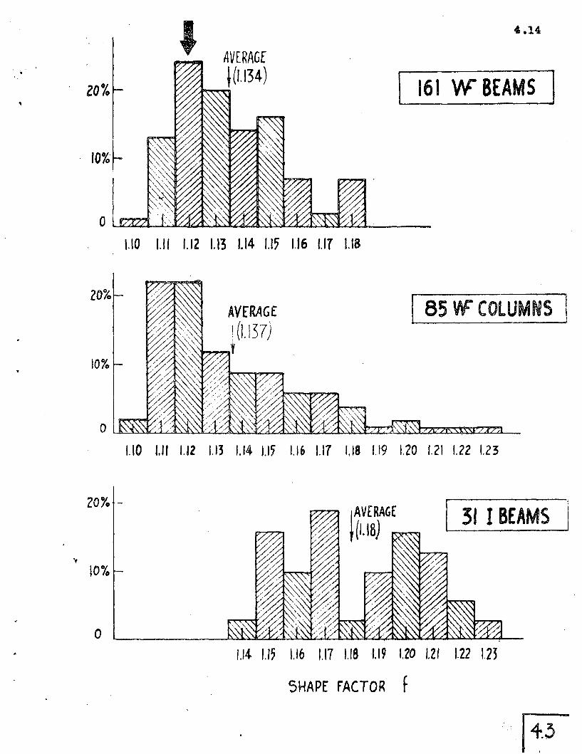
The variation .of the shape factor for WF shapes used as beams,
for WF shapes used as columns, and for I shapes is shown in Fig .403:. '" ., .,9'".- '
For WF shapes normally used as b~ams (and listed in "Sec tion"Econmny"
table in AI$C MANUAL, STEEL CO~STRUCTION)(404) the shape factor varies
from 1010 to 1018 with an.average value of 1.134 and a.mode of 1.12.
For WY shapes normally used as columns (members that appear in the
•
/
205.53(4,8)
. . . (4.4)"column tables" of the AISC MANUAL "STEEL CONSTRUCTION"), , the
shape factor var~es from 1,10 to 1,23 with an average value of 1.137'
and a mode of 1.115. The shape factor distribution of American
,Standard I beams is shown in the lower portion of Fig 4.3. The,
minimum is 1.14 and the maximum is 1~23, the average being 1.18.
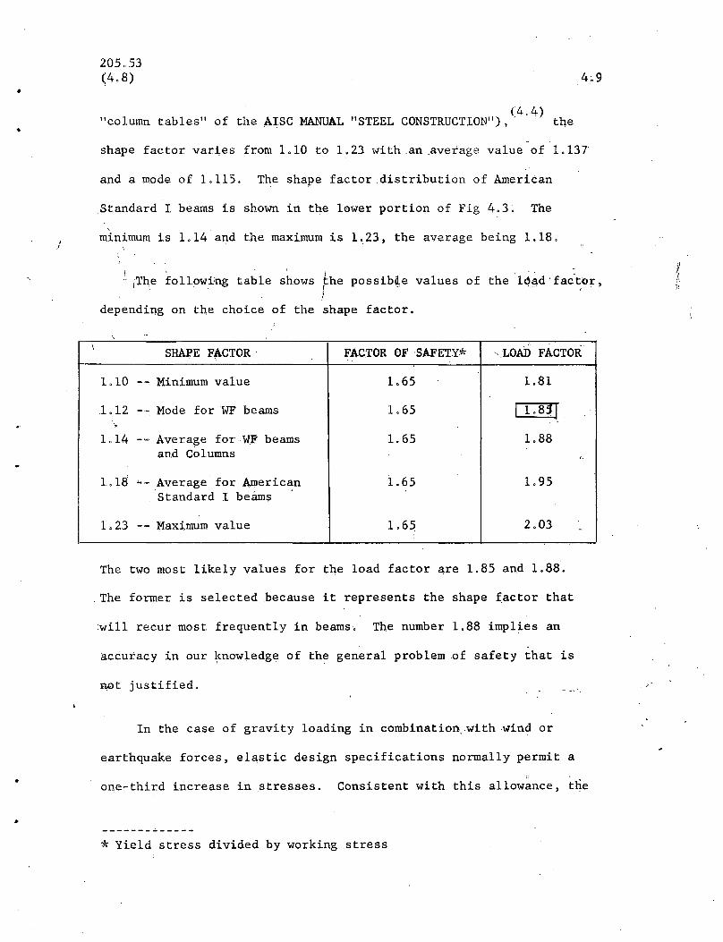
;Th.e follow;i!ng table shows ~he possib~e values of the l~~d fac'tor,I l ''
depending on the choice of the shape factor.
,\ SHAPE FACTOR FACrOROFSAFETY* "LOAD F1\CTOR
1.10 -- Minimum value 1.65 1.81
1.12 -- Mode for WF beams 1. 65 I 1. 83 r"
1.14 -- Average for WF beams 1. 65 1.88and Columns
"
1.18--
Average for American 1.65 1.95Standard I be.funs '.
1.23 -- Maxi.mum value 1.65 2.03 ,.
The two most likely values for the load factor a,re 1.85 and 1.88 .
. The former is selected .because it represents the shape factor that
will recur most frequently in beams. The number 1.88 implies an
accuracy in our ~nowledge of the general problem of safety that is
tWt justified,
In the case of gravity loading in combination, with wind or
earthquake forces, elastic design specifications normally permit a
one-third increase in stresses. Consistent with this allowance, the
* Yield stress divided by working stress
205.53<4;8)
valu~ o£ F for combined dead, liv~, and wind loading would be
3/4 x 1.85 '= 1.40.
4.10
•
Although safety is achieved in plastic design by multiplying
the working loads by a term called a load factor, it is important to
recogni,ze that many other items can vary in add'ttion to the load.
fossible sourdeE? of "error" :Ln design are:
(1) overrun in computed :dead loads
(2) future increases, in live loads
(3) loss of section due to !corrosi~n
(4) approximations inan~lysis
(5) underrun in dimensions
(6) underrun in physical prop~rties
(7) _i l1adequate design theory
(8) errors in distribution of load
(9) errors in fabrication .and erection
(10) presence of residual stresses and stress~oncentrations
Depending upon t~e type of str.ucture and the use intended, the
variation due to one "error" may be larger than another .. While one
might arrive at a new "factor of safety" by determining the magnitude
of possible errors and makint· a statistical estimate, such a change
should also be reflected in the allowable stresses permitted in
elast~c design.. Therefore, all of the possible v~riations have .
been combi~;,4 into a "load factor" which assures that a plastically
,205,53(4.8)
Idesigned sttucturewill have the same degree of safety as does a
.~ .,;
simply-supported beam designed by elastic methods.
4.11
-Although it is recognized that factors other than variation in
load enter into the problem of structural' safety, the .term "load
factor" serves to emphasize that the final test of the suitabili.ty
of a structure rests upon its ability to support'Vili.e load.
·. 205.53
REF E R .E N CE S- - - '- - - - .- - ,-Chapter 4
4.12
•
4.1 LS BEEDLE,A W lWBER, .. "Residual Stress and the Compressivefroperties of SteelII, A:Summary Report, F. L. Report 220A.27,July, 1957.
4.2A ..W HUBER, IIResidual Stress Measllrementll, F. L.Report220A.17,March 1955.
4.3 B THURt.IMANN, IIModification to .Plastic ';rheoryll, Proc. AISC NationalEngineering Conference, p 50, 1956.
4.4 AISC MANUAL, IISTEEL CONSTRUCTIONII
4.5 LA HARRIS, N M NEWMARK, lithe ·Effect of Fabrication Processes onThe Brittle ~ehavior of Steel ll , University of Illinois, 1957 .
30
20
Frequency( %)
10
o
I
.... }--- Average III 0·799
'...-...-
.......- I--
.'
~
-- I:--
.. I I I
0.4 0.5 0.6 0.7 0.8 0.9 1.0
5'.(J!tub...co1~)5') \Mill) .
FREQUENCy DISTRIBUTION OF RATIO
.,;.
30
6"(ksi)
I......_~-- -
20
10
.0
. (Group ,)
4.1
---- Based on measuredresidual stresses
'and assumed d1stri-Ibution·. " .
Average curve for.stub columns.
AVERAGE (S'" € CURVE FCR STUB co:cmws(Group '7 '.
zo%
10%
20%
10%
LlO 1.11 1.12 1.13 1.14 1.17 1.16 1.17 1.18
AVfRAGE\0.137)
,~t
! 16\ W BEAMS I
85 'If COLUMNS
10%
o
1.10 1./1 /.12 1.13 1.14 1.15 1.16 1.17 1.18 1.19 1.20 1.2\ 1.22 1.23
[ 31 I BEAMS i
1.14 1./5 \.16 1.17 1.181.19 \.lO 1.21 1.22 1.23
SHAPE fACTOR f
.·14.~
205.53
5. VE.R I FICA T 10 N o F P L.A S TIC THE 0 R Y
5.1
It is the purpose of this chapter to show that the actual behavior of
structures under test verifies the predictions of plastic theory. Art 5.1 will
be concerned with demonstrating ~hat structural steel contains the ductility
assumed, and that plastic hinges will form and allow the n~cessary redistribution
of moment. Article 5.2 will present the results of continuous beam tests, and
finally Art 5.3 will show how tests of rigid frames verify plastic theory.
5.1 BASIC CONCErTS
1. Ductility. of .. Steel.
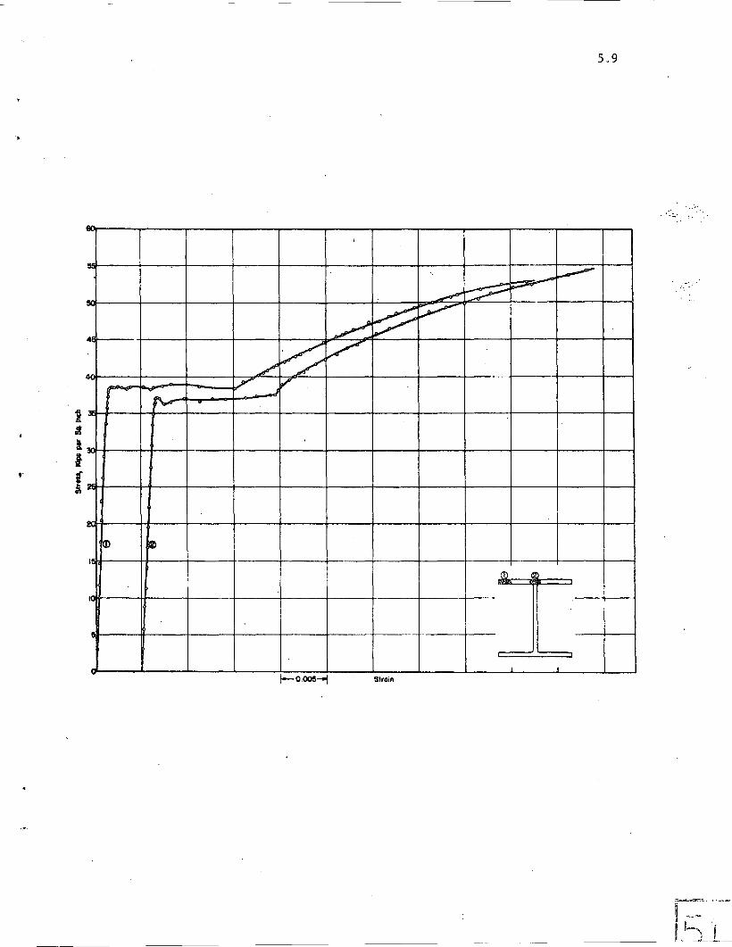
Fig 5.1 shows the tensile stress-strain curve obtained from two coupons
cut from two separate locations of an 8WF40 beam. It is typical of the behavior
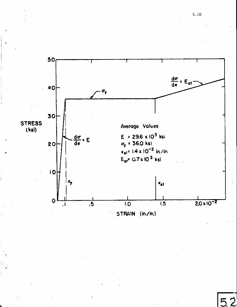
of ASTMA7 steel. Fig 5,2 represents a conventionalized "average" stress-strain
curve for structural steel. It has been .obtained from the considerable number of
compression and tension tests conducted at Fritz Laboratory for the purpose of
evaluating the structural tests performed. Compression tests are of interest
in connection with the plastic behavior of structures because, of course, one
half of the cross section is yielded in compre~sion. The steel deforms plas-
tically about 15 times the strain at the elastic limit and then commences to
strain harden. Although the data is plotted well into the strain-hardening
range, the strains shown are still considerably less than those at ultimate
strength ("tensile strength).* The compressive and the tensile stress-strain
relationsh~ps are quite similar. In fact the properties in compression are
practically identical with those in tension.
* ASTM-A7 requires an elongation in 2-in of not less than 24%, an elongationthat is more than 200 times the maximum elastic value.
205.53
From Fig 5.2 it may be concluded that structural steel coupons do have
the necessary ductility as assume'd in plastic analysis.
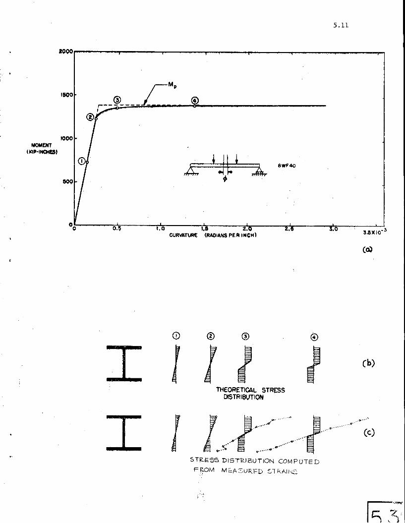
2. The Plastic Moment and the Plastic Hinge
As a demonstration that the plastic moment is a~tained through plasti-
5.2
+.
fic::ation .of the cross section, Fig 5~3fl shows a typical M-0 curve obtained from
a beam in pur~ bending. (5.1) Tqe dotted line is the idealized Gurve and the
solid line through the circles shqws the r~sults of a test. The theoretical
stress distributions (according to the simple plastic theory) at different
stages of' bending are shown in Fig 5.3(b). Below these in Fig 5.3(c) are shqwn
the corresponding stress distributions as determined fromSR-4 gage measurements.
It will be seen that plastification of the cross section does occur, and that
the bending moment corresponding to this condition is the full plastic moment as
computed from the equati.on Mp = OyZ.
Although there will be inevitable minor variations from the result shown in
Fig 5.3 (a) the many tests conducted on rolled shapes indicate that most hot-rolled
wide-flange beams will develop the strength predicted by the plastic theory and
that a plastic hinge (characterized by rotation at near-constant moment) does
actually form.
It is true that a somewhat unrealistic loading co~dition has been taken.
"Pure moment" is a condition not likely to be encountered in actual structures,
but it represents the most severe ~l~ading condition insofar as the plastic
behavior of a beam is concerned. Usually there will be a gradient in moment,
as when a single concentrated load is applied to a beam. In such a case the
deformation tends to be concentrated under the load point (the point of maximum .
moment). Because the plastic deformation is more localized, the strain-hardening
205,53
region is reached at a lesser deflection; consequently, the beam tends to
5,3
develop a moment greater than the plastic moment. Typical of the behavior of
(5.2)a beam under moment gradient is that shown in Fig 5.4. The beam continues
to increase in load-c~rrying capacity as the deformation is continued.
Thus strain-hardening improves the moment-carrying capacity of a beam.
Although it is neglected in the simple plastic theory (except for checking a
beam for stability against buckling) this additional reserve strength is still
present in .most ordinary structures, and this contributes to a greater than
assumed actual factor of safety.
3, . Redistribution of Moment
From the previous section it is seen that plastic hinges may be depended
upon to form at connections and at concentrated load points. This development
of this plastic moment is one of the sources of reserve strength in structural
steel, Another source is the redistribution .of moment in continuous structures.
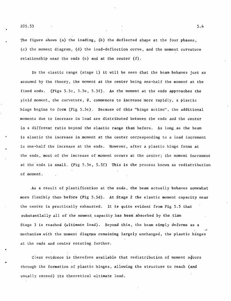
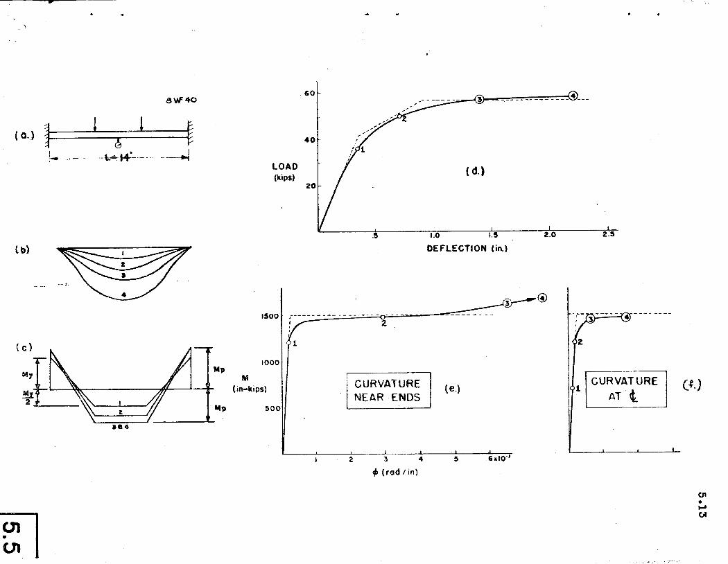
In Fig 5.5 is shown a picture of the redistribution process -- as predicted
theoretically and as obtained: experimentally..A test was made ona continuous
(4.3)beam to simulate the condition of third-point loading on a fixed-ended span;
thus experimental data was available to compare with the theoretical predictions.
The fixed-ended beam and its various components are shown in four stages:
Stage 1
Stage 2
Stage 3
Stage 4
near the computed elastic limit.
after the plastic hinge has formed at the e~ds and theload has increased towards its ultimate value.
when the theoretical ultimate load is first reached, and
after deformation has been continued through an arbitraryadditional displacement.
205.53 5.4
•
The figure shows (a) the loading, (b) the deflected shape at the four phases,
(c) the moment diagram, (d) the load-deflection curve, and the moment curvature
relationship near the ends (e) and at the center (f).
As a result of plastification at the ends, the beam actually behaves somewhat
more flexibly than before (Fig 5.5d). At Stage 2 the elastic moment capacity near
the center is practically exhausted. It is quite evident from Fig 5.5 that
substantIally all of the moment capacity has been absorbed by the time
Stage 3 is reached (ultimate load). Beyond this, the beam simply deforms as a
mechanism with the moment diag~m remaining largely unchanged, the plastic hinges
at the ends and center rotating further .
Clear evidence is therefore available that redistribution of moment oqcurs
through the formation of plastic hinges, allowing the structure to reach (and
usually exceed) its theoretical ultimate load.
205.53
5.2 CONTINUOUS BEAMS
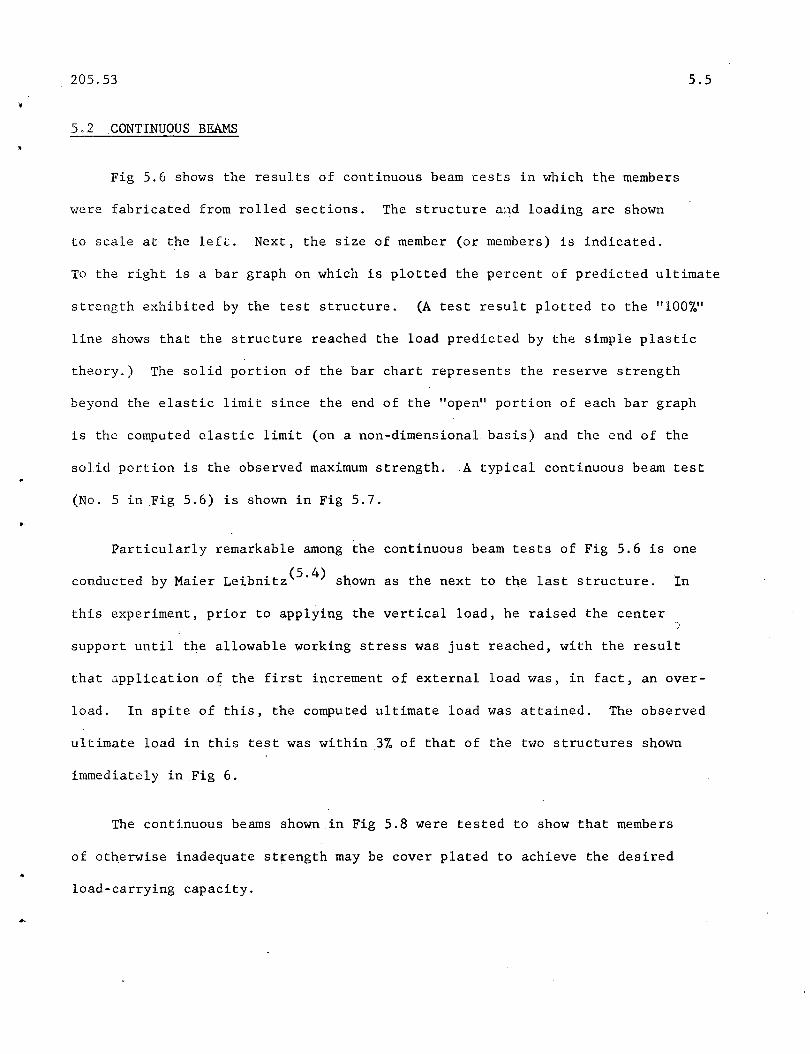
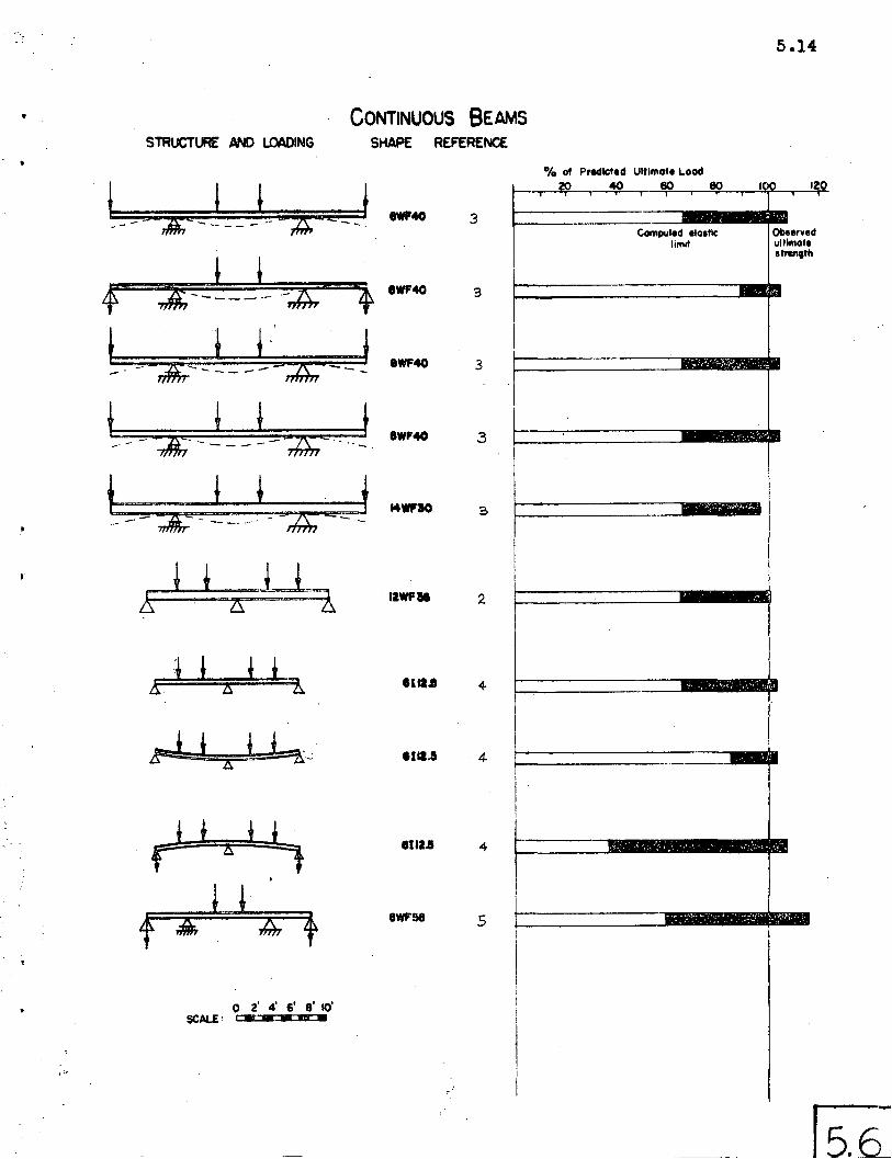
Fig 5.6 shows the results of continuous beam tests in which the members
were fabricated from rolled sections. The structure and loading are shown
5.5
to scale at the left. Next, the size of member (or members) is indicated.
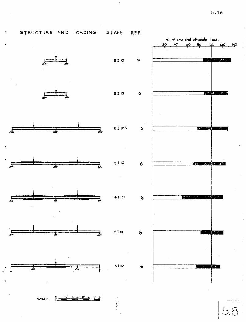
To the right is a bar graph on which is plotted the percent of predicted ultimate
strength exhibited by the test structure. (A test result plotted to the "100%"
line shows that the structure reached the load predicted by the simple plastic
theory.) The solid portion of the bar chart represents the reserve strength
beyond the elastic limit since the end of the "open" portion of each bar graph
is the computed elastic limit (on a non-dimensional basis) and the end of the
solid portion is the observed maximum strength. A typical continuous beam test
(No.5 in Fig 5.6) is shown in Fig 5.7.
Particularly remarkable among the continuous beam tests of Fig 5.6 is one
conducted by Maier Leibnitz(5.4) shown as the next to the last structure. In
this experiment, prior to applying the vertical load, he raised the center
support until the allowable working stress was just reached, with the result
that application nf the first increment of external load was, in fact, an over
load. In spite of this, the computed ultimate load was attained. The observed
ultimate load in this test was within 3% of that of the two structures shown
immediately in Fig 6.
The continuous beams shown in Fig 5.8 were tested to show that members
of otherwise inadequate st~engthmay be cover plated to achieve the desired
load-carrying capacity.
205.53 5.6
.'
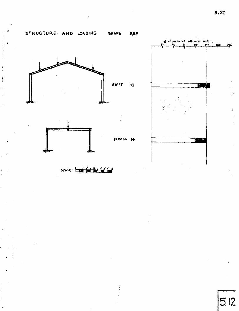
5.3 FRAMETESTS
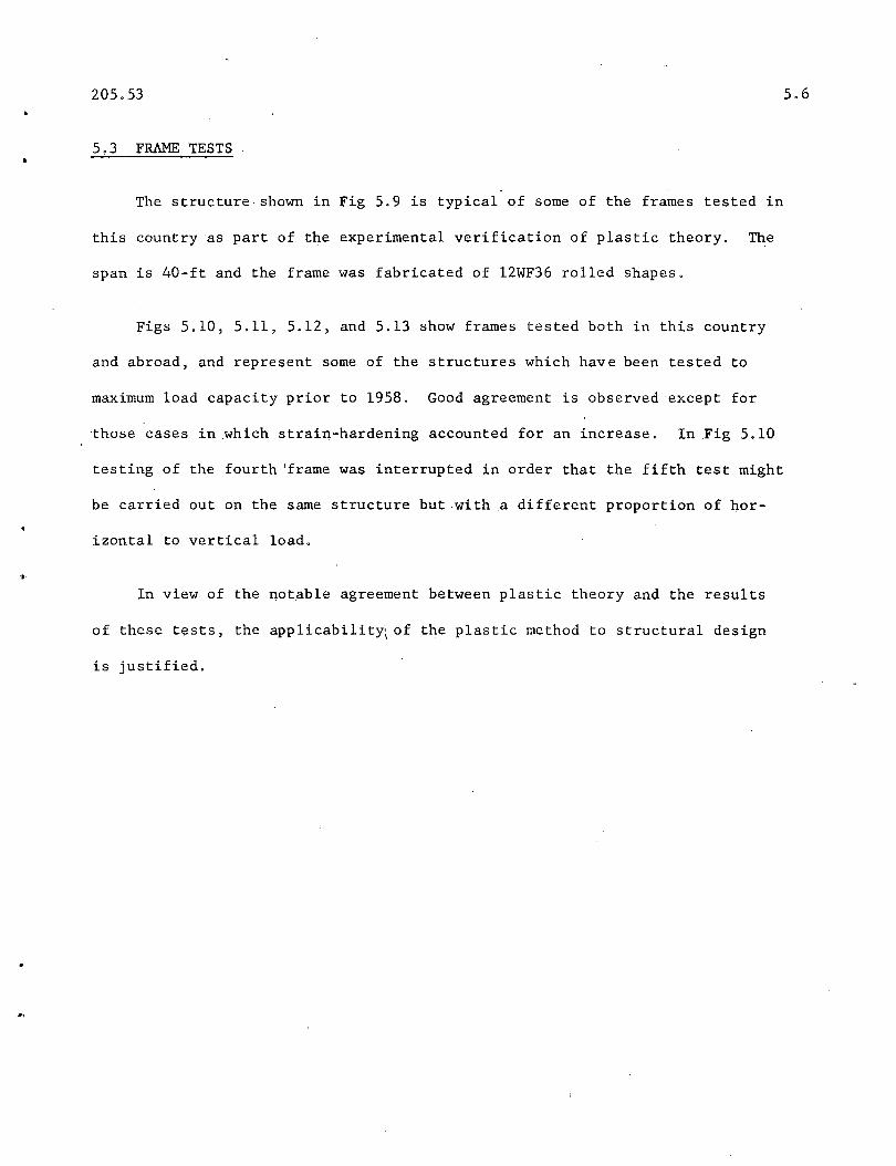
The structure, shown in Fig 5.9 is typical of some of the frames tested in
this country as part of the experimental verification of plastic theory. The
span is 40-ft and the frame was fabricated of l2WF36 rolled shapes.
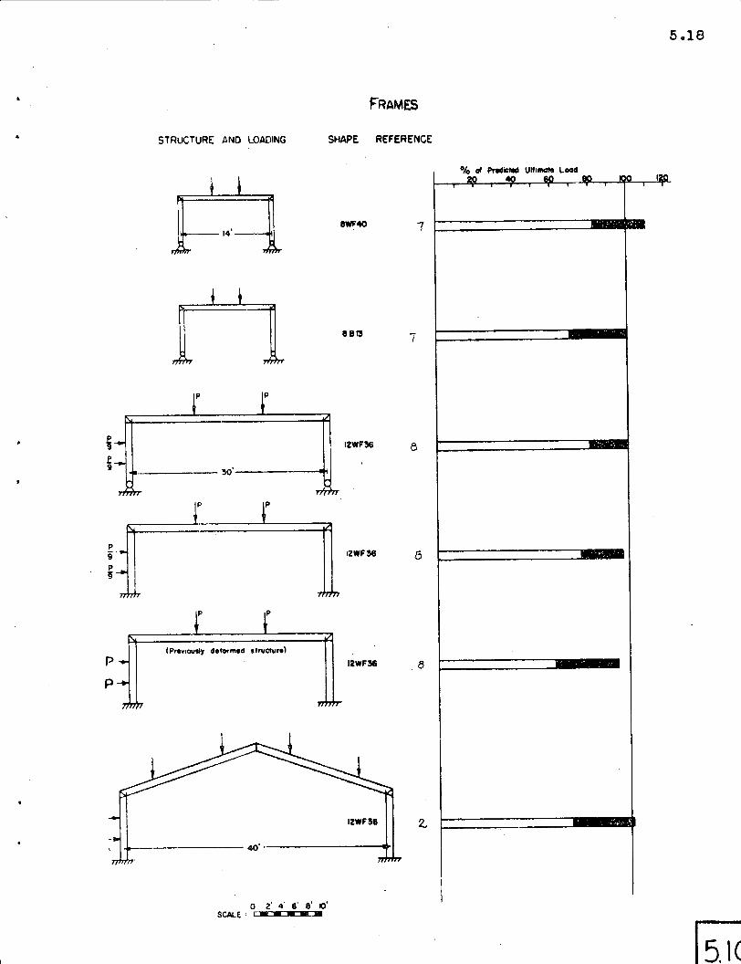
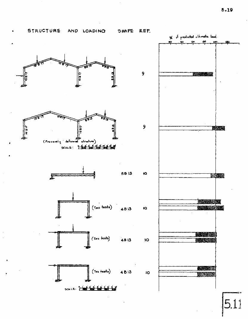
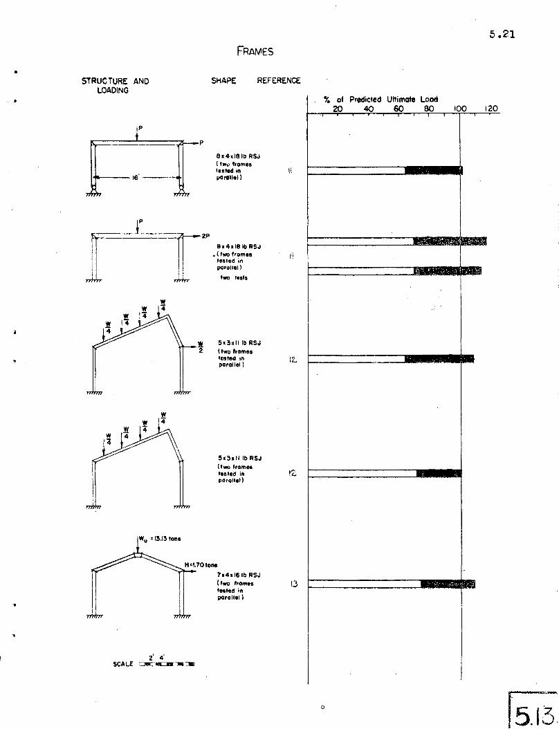
Figs 5.10, 5.11, 5.12, and 5.13 show frames tested both in this country
and abroad, and represent some of the structures which have been tested to
maximum load capacity prior to 1958. Good agreement is observed except for
,those cases in .which strain-hardening accounted for an increase. In Fig 5.10
testing of the fourth 'frame was interrupted in order that the fifth test might
be. carried out on the same structure but·with a different proportion of hor
izontal to vertical load .
In view of the notable agreement between plastic theory and the results
of these tests, the applicability\ of the plastic method to structural design
.is justified.
REF ER E N C E S- - '- - - - - - .- -
Chapter 5
I
I
I
I~
5-1 Luxion, Wo & Johnston~ B. G.
5-2 Driscoll, G. C. & Beedle, L. S.
5.,3 Yang, C. H., Beedle, L. S. &Johnston, B. G.
5-4 Maier-Leibnitz
5-5 'Hall, W. J. & Newmark, N. M.
5-6 POROV,.E. P., Willis, J. A.
5-7 Ruzek, J., Knudsen, K. E.,Johnston, E. R., & Beedle, L. S.
5-8 Schilling, C. G., Schutz, F. W.& Beedle, _L. S.
5-9" DriscolL G.C., Lu, L. W.
5-10 Nelson, H. M.; Wright, D. T.,& Dolphin, J. W.
5-11 Baker, J. F. & Roderick, ~. w.
"PLASTIC BEHAVIOR .OF WIDE FLANGEBEAMS, Weld. Jour. 27(11),November 1948.
"THE PLASTIC BEHAVIOR OF STRUCTURALMEMBERS AND FRAMES"., We ld. Jour.36(6) p 275-s, June 1957.
"RESIDUAL .STRESS AND THE COMPRESSIVESTRENGTH OF STEEL BEAMS", Weld.Jour. 31(4) April, 1952, p 205-s
"CONTRIBUTION TO THE PROBLEM OFUL'II.MATE CARRYING CAPACITY OFSTMPLE AND CONTINUOUS BEAMS OFSTRUCU;URAL .sTEEL AND TIMBER",Die Bautechnik, 1, 6 (1947),Abstract available as Fritz Laboratory Report No. 205.15.
"SHEAR DEFLECTION OF WIDE FLANGEBEAMS IN THE PLASTIC RANGE",Trans. ASCE, 122, 666 (1957)
"PLASTIC DESIGN OF COVER PLATEDCONTINUOUS BEAMS", ASCE Jour.,
84(EM-l) 149s-1 (1958)
"WELDED PORTAL FRAMES TESTED TOCOLLAPSE", Welding Journal, 33(9),September 1954.
"BEHAVIOR OF WELDED SINGLE ,SPAN'FRAMES UNDER COMBINED LOADING"
"TEST OF TWO-SPAN GABLED PbRTALFRAME", Fritz Laboraf:ory Reporton preparation.
"D~ONSTRATIONS OF PLASTIC BEHAVIOROF STEEL FRAMES", ASCE Proceedings,Paper 1390, October 1957.
"TEsrs ON FULL-SCALE. PORTAL FRAMES",Inst. C. E. (~r.), January 1952.
"
5-12 Baker, J. F., & Eickhoff, K.. G.
5-13 Baker, J. F., & Eickhoff, K. G.
5-14 B1essey, W. E.
5.8
"THE BEHAVIOR OF SAW TOOTH PORTALFRAMES", Conference on the Corre1at.ion between Calculated and Observed Stresses and Displacementsin Structures. Institute ofCivil Engineers, 1955, p. 107.
"A TESTON A PITCHED ROOF PQRTAL",Br. Weld. Res •. Assn. Report No.FE 1/35, January 1954.
A letter report from Mr •. Wa1terE. B1essey,-~Tu1ane University,February 7, 1958.
->
,-
5.9
I
~- '. .-
~-~....
~~
~4
~ /./ /.... T Vr ov
....."" .-J
..~
_.
.....
~ ~
-I
(f)
I...
II . f-------
..... ~:;.- ~."
I, I
~
5.10
50-----r-------,r-----;-------,.--,
STRESS(kll)
40
Average Voll.les
E ;: 29.6 x10³ ksiO"y :; 36.0 ksi
0-2. .re It:: 1.4 Jt I In./ln,
E.t=0.7.10' k~i
10
oLJ"L__,.J-s---~I.O::----!-7t.~5---~l;i()=r-
5TRAIN (in./in.)
5.11
2000-----t""'-----,.----or-~--..,...--~....,...---""""""' r'J
4
MOMENT(KIP-INCHES)
8WF4Q
~.
oO'---.....-.-=O.l:.~-----:'I.&::.O:----~ln.D.------::z;4;.,.----~2n.r------.:tn-----:--S
.-&)(-"I~O.3CURVATURE (RADIANS PEA INCH)
(0)
®
I / II (b)
ITHEORETICAL STRESS
DISTRI6UTION
I 1 /-.o•.•••••/~··--·····O .. 0 0 •... 0- ,'
. ..... (c)•• ' .,0"- ••••••• .,. •••• ~ ••
. .... O'".~O 0 •.•. ··.·#
STg,E,5S DISTE.I13UTION COMPUTED
F~M MEASUR.FD s-r kt'\Ii'C
:'.\; .
r;;-:.Z~.·~'.I~ ~o_
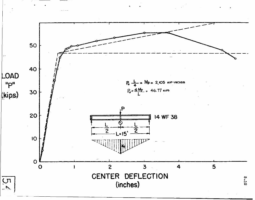
R, ~ = Mp:: 2.105 "UJ-n,c"~s
R,= 4-rf.- = 46.17 ¥alPS
------------~::::::~~----......................----------50
30
40DAD
p
20
'0 .
1'I=1f====¥=======YIRt 14 WF 38L ~ Lr -2~
~ 2" L=15t ~
~QllJllJ]1
oO~--~l----:--_-J-_----'--":"-__..J.-_--2 3 4 5
CENTER DEFLECTION(inches)
•
.60
LOAD(kips)
.5
-------- 3
( d.)
1.0 1.5
_. 4 _
2.0
DEFLECTION (in.)
(~.)I ,1 CURVATUREAT It.
. 1
1500 ,------ - - -- - - - -_._- --I 2,
1000M,
M(in-kips) CURVATURE (e.)
NEAR ENOSM1» sao
•• 4
(c)
l b)
2 3 4
4>. (rad / in)
STRUCTURE AND LOADING
CONTINUOUS BEAMSSHAPE REFERENCE
5.14
~ •.,40
I sj£t __~_ *;zr; eJ::t--t:=J--;;;:;;
t = 1 tz: t- .. -- ;.jfjij,..-- - - - - - ;;{;;; - - - 8WF4O
8WF4O
14.,10
IIWII
3
3
3
.3
2
I
0/0 of Predicted Ultlmote Load20 40 60 80
i i
Computed elostlc:limit
• • "', :';', H '; ""1 \
1111.1
1111.1
..
~ iJ., 1112.1 42i
tt * t 8WF'68Ai A 5
o 2' 4' 6' .,' l()'SCALE ' c:a:=-:...
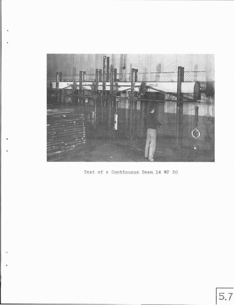
Test of a Continuous Beam 14 WF 30
STRUC. TURE. AN D LOADING
tF==I=~=j=~::JJi;. .£ ~
ETA::::::=;.::::: H __
l=r= ;: ).
5 HI\PE REF.
5110
5 110
6 I 12.5
5 I 10
41'7.7
5 I 10
5.16
, J.. : ',:--":~. :.'.r .. :.
,". ,,- '~' 1. •• : ~~ ,1', ,
" . '.":" ~~.. :,~~,',:."
SCM.e: r-----·15.8!
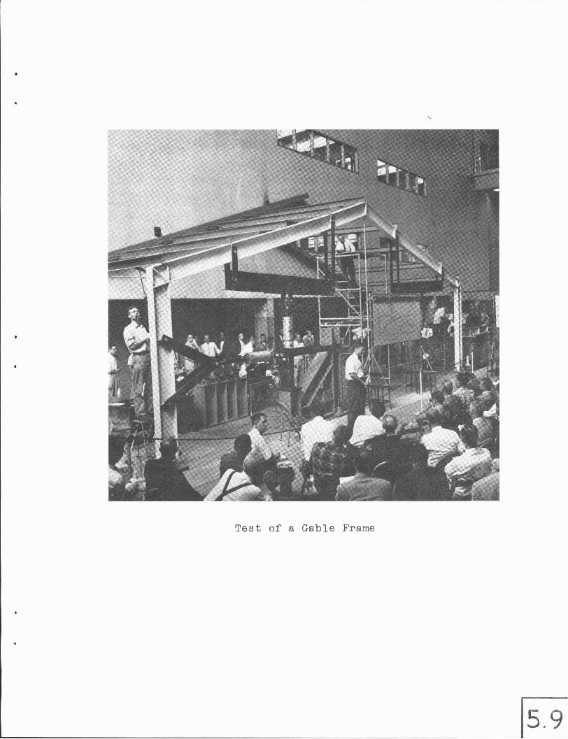
Test of a Gable Frame
5.18
FRAMES
STRUCTURE AND LOADING SHAPE REFERENCE
OJ, rJ Predic*l Ultimate Load':.n~ Ml M BO lCiO 120
I
7
{;
.8
e
12W'36
12.'36
IZW'36
1~--14'--~1
(Pr,vlOUsly delo<",.d slFl,Cfurel
,....------30'-------
p
9p9
lf9
p
p
o 2' 4' S' e' 10'SCALE: I ••• ••
It STRUCTURE AND LOAD/NO'
("re"IO~I~ . o\e~.nn.l Q~f'~)
~L\~1<: : ~.W1,1 W1rI
9
" '~rre"i~ \I\+\~e. I«UI.co 60 6Cl 100
B&'~ ,Q
10
to
10
•
•
~TF\Uc.TUF\e· Ii\ND LOADING
oj. of..-~'ZD~,.......:Ji~"""':;~~!..-..-r..J:r:"""'..l4flj:...,......qO
,
8,*17 10
,.~'; ..
•
5.21
FRAMES
•
•
STRUCTURE ANDLOADING
SHAPE REFERENCE
'0 of Predicted Ultimate Load20 40 60 80 100 120
p
.,.---_-_==--=---.....-_-_::::::::-:.--,ot.--p
--16'----·
Bl41181b RSJ(tW<l !,omesleaf.d inI/orollel)
I
I
I
12.
,"."-
51311lib RS,J(two f,omesfflSted inpo,ollel )
!h3.11 Ib RSJ(two I,omeste&led inpo,ollel)
H=1.70tone
7a41161b RSJ(two fromes 1,3tilted inporollel)
2' 4'SCAL~ =-:;:lIII3I£-..=-
K"_-r_-~T2P
Sa 41lBIb RSJ" • (!wo !,om••
fIsted inpo,Ollel)
two lOlls
o
•205.53
6. SEC 0 N DAR Y DEBIGN'CONSIDERATIONS
6.1
l,
"
6.1 SHEAR FORCE (Article to be prepared)
A brief outline of the theoretical solution to the problem will be
given and the results of tests will be shown.
A design approximation has been developed to indicate when shear force
will be critical. It is of the form,
Vmax '= 18.000 wd
,where V is the shear force in pounds, w is the web thickness in inches, and
d is the secti.on depth in inches. This approximation will be derived and
examples will be given to illustrate its use.
6.2 LOCAL BUCKLING (Article to be prepared)
Based on work recently completed, this article will summarize the
essential steps in the theoretical analysis of the buckling of flanges and
webs of wide flange shapes, when failure takes place in the inelastic range.
By requiring that an element sustain the yield load until the strain reaches
strain-hardening, a solution to the problem is achieved.
The results of correlating tests will be presented, followed by the
presentation of a design guide to assure that compressive strains may reach
,and even exceed Est without premature failure (b/t~ 17, d/w ~ 55).
•205.53 6.2
•
•
This article will review the work that has been done on repeated loading
as it applies to plastically design structues, Pertinent test.resultswill
be shown.
6.3 LATERAL BUCKLING (Article to be prepared)
Although tentative solutions to the problem of lateral buckling of beams
in the' plastic range have been prepared, the problem is not completely solved.
This'article will summarize. the theoretical and experimental work that has
been done and will indicate t.he procedures that seem most appropriate in view
of present st.ate of knowledge. Design appnoximations and illustrative examples
will be shown,
6.4 AXIAL FORCE AND COLUMN BUCKLING
The simple plastic theory assumes that the full. plastic hinge value is
available in all. members, and that failure of a frame. (in the sen~e that a
mechanism is formed) is not preceeded by column instability. This article
will pr~'sent methods of determining the amount by whi.ch the prfsence of
axial force tends to reduce the magnitude of the effective plastic moment,
and will indicate the solutions that have been obtained to the problem of
a column loaded with axial force and end moments, These solutions will be
compared with tests carried out both in this country and abroad and will
suggest a designapprpximatiqn based on these findings .
. As in the case of lateral bl)ckling, the entire problem is not completely
solved, ·However, solutions are available for certain practical loading con-
ditions. These will be presented, and the areas of remaining work will be
outlin~d.
205,53
6.5 REPEATED LOADING (Article to be prepared)
6.3
Ina large majority of practical cases, the ultimate load is not influenced
by the fact that there is some variation in the loading.: The number of cycles
may be small or the magnitude of variation in an individual load may be incon
sequential. There may be cases, however, where a major part of the loading
may fluctuate for a consider~ble number of cycles.
'.
205.53
Chapter 7
CON N E C T ION S
(To be completed)
Connections must be proportioned in such a way that they will transmit
the plastic moment and have adequate rotation capacity. Theoretical and
experimental studies have· shown that connections can be 'fabricated econom
ically and still meet these requi.rements.
7.1
This chapter will first outline the specific requirements that different
types of connections must fulfill. Next the various connection types will
be discussed, and in each case the method of analysis will be given, exper
imental correlation will be shown, and a suggested guide for proportioning
the element will be presented. The methods will be illustrated by examples.
The following types of connections will be considered:
(1) Straight corner connections
(2) Haunched connections (tapered and curved)
(3) Beam-to-column connect.ions
(4) Beam-girder connections
(5) Miscellaneous building connections
(6) Splices
(7) Details with regard to welding
(8) Details with regard to bolting
205 • .5.3
Chapter 8
8.1
8.1 DEFLECTIONS
MIS C E L LAN E 0 U S
(To be completed)
R E QUI REM E N T S
•
"
This article will review some of the methods for computing deflections
for structures designed by the plastic method. Although the determination
of the load-vs-deflection relationship is too complicated to be of practical
value, by making certain simplifications with regard to the M-0 relationship,
the problem may be reduced to one that is no more complicated than that of
computing the elastic deflection of a frame once the moment diagram is known.
Comparison will be made between computed deflections and those observed
in tests.
This article will also discuss the importance of deflection 'as a design
requirement. Actually, it is a secondary one, s;i!nce,the;important function
of a structure is to carry load. Comparison of deflect'ions at working load
for plastically-designed structures will be made with deflections of conven-
tionally-designed structures (simple-beam design). Such a comparison leads
to the conclusion that a structure designed plastically will usually deflect
no more at working load than a structure designed elastically according to
current specifications .
..
205.53
LIMIT LOAD -- The load under which a structure reaches a defined limit ofstructu~al usefulness.
ULTIMATE LOAD -- The -load attained when.a sufficient number of yield zoneShave formed to permit the structure to deform plastically without furtherincrease in load. It is the largest load a structure will support, when sucrfactors as instability and fracture are excluded.
LIMIT DESIGN --"A design based on any chosen limit of structural usefulness.
10.1
ELASTIC DESIGN -- A design method" which defines the limit of structural usefulness as the load at which a calculated stress equal to the yield point ofthe material is first attained at any point (usually disregarding local stressraisers) .
PLAST1f DESIGN -- A design method which .defines the limit of structural use~
fulness as the "u ltimate load". (The term, " p l as tic" comes from the fact thatthe ultimate load is computed from a knowledge of the strength of steel in theplastic range)
FACTOR OF SAFETY -- As used in conventional elastic design, it is a factor bywhich the yield stress is divided to determine a working or allowable stress forthe most highly stressed fibreo
LOAD FACTOR -~ In plastic design, a factor by which the working load is multiplied to determine the ultimate load. This choice of terms serves to emphasizethe reliance upon load-carrying capacity of the structure rather than upon stress.
YIELD MOMENT -- In a me~er subjected to bending, the moment at which an outerfibre first attains yield. point stress.
PLASTIC MOMENT Resistin~moment of a fully-yielded cross-section.
PLASTIFICATION Gradual penetration of yield stress fromtowards the centroid of a section under increasing moment.complete when the plastic moment, Mp , is attained.
the outer fibrePlastification is
•
PLASTIC MODULUS -- The resisting modulus of a completely yielded cross section.It is the combined statical moments about the neutral axis of the cross-sectionalareas above and below that axis .
. SHAPE FACTOR -- The ratio Mp/My , orZ/S, for a cross-section.
PLASTIC HINGE -- A yielded zone which.forms in a beam when the plastic mom~nt
is applied. The beam rotates as if hinged, except that it is restrained by themoment Mp .
HINGE ANGLE (H) -- The angle of rotation through which a yielded segment of abeam must sustain its plastic moment value.
10.2
11
'.".
ROTATION CAPACITY -- The angular rotation which a given cross-sectional shapecan sustain at the plastic moment value without prior local failure.
MECHANISM -- Anarti~ulated system able to deform without a finite increase inload. It is used in the special sense that the linkage m~y include real hingesand/or plastic hinges.
REDISTRIBUTION OF MOMENT -- A process which results in the successive formationof plastic hinges until the ultimate load is reached. As a result of the formationof plastic hinge, less-highly ~tressed portions of a structure may carry increasedmoments.
PROPORTIONAL LOADING All loads increase in a constant ratio, one to the other,and without repetition, to a maximum .value.
•
20.5.,53
NOME NC L.A T U RE
10.3
A = Area of cros~-section
Af Area of t.wo flanges of WF shape, Af = 2bt
Ap = Cross-sectional area of plate
Aw = Area of web, Aw = wd
a = Column hei.ght to span length ratio of gable frame (column height = aL).
= Dist.an.ce between, cen..troids of cross-sectional areas above and pelowneutral axis,
= .:Oi.stan.ce from e.~.d o.f canti.lever to critical section .ofbeam.
b - Flange wi.dth
Breadth of rectangular cross section.
=
• c
Roof rise to span length ratio of ¢.able frame (roof rise
= Overturning moment parameter (windward side)
bL) .
Cf = Correctionfacto.r due to end fixity (restraint) for determiningcritical length for lateral buckling.
c = Distance from neutral axis to the·extreme fiber.
D Overturni.ng moment parameter (leeward) side.
d = Depth of section
df = Dist.ance between centers of two flanges.
dp Distanc.e between two cover plates.
~ Web depth ofWF shape (d - 2t)
E = Young's modulus of elasticity
Est St.rain-hardening modulus = do.-d'Est
Et = Tangent modulus•
e = Eccentricity
;'\
F = Load factor of safety
f Shape factor = ~ ZMy S
•
205.53 10.4
G Xodulus of elasticity in shear.
Gst- Modulus of elasticity in shear at onset of strain-hardening.
Gt Tangent modulus in shear.
gA = Moment ratio in adjacent segment.
H = Hinge angle required at a plastic hinge.
= Horizontal reaction
HB .Portionof hinge angle that occurs in critical (buckling) segmen~ of beam.
h Story height in multi-story frame.
I
Ie
I pI
I w
K
KL
k
= Moment of inertia; subscripts denote axis.
= Number of redundants remaining ina structure at ultimate load.
= Moment of inertia o·f elastic part of cross-section.
= Moment of i.nertia of plastic part of cross-section.
Warping constant
= Torsion constant
Effective (pin-end) length of column. K= Euler length factor
= Distance from flange fac~ to end of fillet
= Plastic moment ratio
= Stiffness factor of a beam
I. = Span length
- Actual column length
= Length of bar
Lcr
=
=
Length of buckling (critical) segment
L~ngth of segment (slope-deflection equation)
Critical length for lateral buckling
L:g,Ls=Critical length (withC = 1.0) of adjacent spans; subscripts:g and sdenote larger and shorter critical lengths, respectively.
61. Equivalent length of connection
= Length of plastic hinge
205.53 10.5
•M = Bending moment
Number of plastic hinges necessary to forma mechanism
Mcr = Critical moment for lateral buckling .of a beam
Mh Moment at the haunch point
Mmax = Maximum moment
Maximum moment of a simply-supported beam
Column end moment; a useful maximum moment
= Plastic moment
Plastic hinge moment modified to include effect of shear force
Moment at which initial outer fiber yield occurs when axial thrustis present.
Moment at working (service) load
Moment at which yield point is reached in flexure.
Number of possible plastic hinges.=
=
= Plastic hinge moment modified to include the effect of axialcompression.
'Me
Mp
Mpc
Mps
Ms
Mw
My
•Myc
N
= Normal force.
n Number of possible independent mecqanisms
= ,Shift of neutral axis.,
P = Concentrated load.
Pe = Euler buckling load
Pmax = Maximum load
Ps Stabilizing ("shakedown") load.
Pt Tangent modulus load.
C:J Pu Ultimate load (theoretical)
Pw = Wor:king (allowable) load.....
Py = Axial load corresponding to y eld stress level; P = Aoy . Loadon beam when yield point is r ached~in flexure.
205.53 10.6
Q bja = roof rise + column height
.R = Rotation capacity
= Radius of curved haunch
r = Radius of gyration; subscripts denote flexure axis
S = Section modulus, lie
S~ = Section modulus of elastic part of cross section
s = Length of compression flange of haunch
T = Force. Horizontal load applied at eaves which produces overturningmoment about the base of the structure equivalent to that of horizontaldistributed load.
t Flange thickness; subscripts c and t denote compression and tension.
t s = Stiffener thickness.
ttr = Transverse stiffener thickness
• v = Shear force
Vmax = Maxi,mum allowable shear force.
u,v,w= Displacements in x, y, and z directions.
w
w
Total distributed load
= External .work due to virtual dIsplacement
= Internal .work due to virtual displacement
= Distributed load per unit of length
= Web thickness
x = Number of redundancies in original structure.
x = Longitudinal coordinate
= Distance to positiopof plastic hinge under distributed load
y
Yo
= Transverse coordinate
= Ordin~te to furthest still-elastic fiber
= Distance frommidheight to neutral axis
205,53
y = Distance from neutral axis to centroid of half-area
10.7
Z
=
Plastic modulus, Z
Plastic modulus of
=Mp0 y
elastic portion of cross-section
.Zp = Plastic modulus of plastic portion of cross-section
Zt = Trial value ofZ, neglecting axial force
z = Lateral coordinate
0( = Central ang~e between points of tangency of curved connection
)9 = Angle between two, non-parallel flanges
6. = Virtual displacement
J = Deflection, Subscripts u, w, y denote deflection at ultimate,working, and yield load respectively .
• € = Strain
Emax = Elongation at fracture
Est = Strain at strain-hardening
Ey = Strain corresponding to theoretical onset of plastic yielding
9 = Measured angle change, rotation
Mechanism angle
fL = Poisson's ratio
f = Radius of curvature
° = Normal stress
ely Lower yield point
0 p = Proportional limit
Or = Residual stress
Cult = Ultimate tensile strength of material<)
Guy = Upper yield point
Ow = Allowable (working) stress
0y = Yield stress level
r
{;
205,53
~ = Shear stress
~y = Shear yield stress
o = Rotation per unit length, or average unit rotation; curvature.
0p = Mp/EI
0st = Curvature at strain-hardening
= Curvature correspopding to fir~t yield in flexure.I
10.8