Embed Size (px)
Citation preview
On Divergence-Angle Efficiency of a Laser Beamin Free-Space Optical Communications for
High-Speed TrainsYagiz Kaymak, Student Member, IEEE, Roberto Rojas-Cessa, Senior Member, IEEE, Jianghua Feng,
Nirwan Ansari, Fellow, IEEE, Mengchu Zhou, Fellow, IEEE
Abstract—We first compare two different laser beam modal-ities, narrow and wide beam, in a free-space optical (FSO)communications system for ground-to-train high-speed traincommunications in which we analyze the trade-offs among receiv-ing power, coverage area, and the complexity of the acquisition-tracking-pointing (ATP) mechanism. We then propose to employa divergence angle of a wide beam in the range [0.07◦, 2.002◦]to relax the steering speed of the fast steering mirror (FSM),which is one of the major components of the ATP mechanismin an FSO transceiver. In addition, a beam using a divergenceangle in the proposed range allows us to overcome the negativeeffects of vertical vibrations induced by the train’s motion. Theproposed range of divergence angles provides a large link rangeand effective coverage length and contact time as compared to anarrow beam.
Index Terms—free-space optical communications, optical wire-less communications, high-speed train communications, beamdivergence angle, wide beam, narrow beam.
I. INTRODUCTION
H IGH-SPEED trains (HSTs), which travel at speeds of300 km/h or faster, play an increasing role in public
transportation as the number of passengers traveling in themincreases. For example, the number of HST passengers inChina has increased from 128 million in 2008 to 672 millionin 2013, which represents an annual growth of approximately39% during that period [1]. Because of the increasing numberof passengers, the demand for high-speed Internet access onHSTs is also on the rise [2].
Several technologies are being considered for HST com-munications. Radio frequency (RF) wireless technologies arecurrently being used to provide Internet access to HST passen-gers [3]. Wireless fidelity (Wi-Fi), worldwide interoperabilityfor microwave access (WiMAX), and leaky coaxial cablesare employed to provide Internet access to HSTs in severalcountries, but they cannot provide high data rates due tointerference, bandwidth limitations and the inherent limiteddata rates of RF technology [4]–[8]. Wi-Fi and WiMAX can
Copyright (c) 2015 IEEE. Personal use of this material is permitted.However, permission to use this material for any other purposes must beobtained from the IEEE by sending a request to [email protected].
Y. Kaymak, R. Rojas-Cessa, Nirwan Ansari, and Mengchu Zhou are withthe Networking Research Laboratory, Department of Electrical and ComputerEngineering, New Jersey Institute of Technology, Newark, NJ 07102. Email:{yk79, rojas, nirwan.ansari, zhou}@njit.edu.
Jianghua Feng is with CSR Zhuzhou Institute Co., LtD, Shidai Road,Zhuzhou, Hunan Province, China Email: [email protected].
Manuscript received XXX, XX, 2016; revised XXX, XX, 2017.
potentially deliver peak data rates of up to 75 Mbps, but theactual data rates are lower than 10 Mbps [9].
Free-space optical (FSO) communication is an alternativeapproach. This is a line-of-sight technology that uses mod-ulated light to transfer data through air, vacuum, or outerspace [10]. An FSO communications system comprises threestages: a transmitter to send the optical signals, a free spacetransmission channel, and a receiver to acquire the transmittedsignals. Each party (i.e., the transmitter and receiver) is usuallyequipped with a transceiver that functions as a transmitterand receiver at the same time to provide full duplex FSOcommunications. In the remainder of this paper, we assumethat each party; a train and a ground base station (BS),is equipped with a transceiver. Laser diodes operating atwavelengths between 780 and 1600 nm are usually preferredas the light sources for this application because they mayprovide high data rates over long distances. For instance, FSOsystems are expected to provide data rates in the range ofGigabits per second for HSTs [2], [11]. FSO systems also haveadditional benefits over RF technologies including immunityto electromagnetic interference and high security owing it tothe use of directed light and of an unregulated range of thespectrum [3], [10].
Both parties in an FSO communications system must bealigned carefully to point the transmitting laser beam tothe receiver [12]. Alignment is even needed for stationarytransceivers. For example, building-to-building FSO commu-nications use alignment and tracking mechanisms to handlethe motion of transceivers generated by thermal expansion,wind sway, and vibration [12]. This alignment mechanism isusually called acquisition-tracking-pointing (ATP) [13]. Thealignment of the beam and receiver becomes challenging whenthe transmitter, receiver, or both parties are in motion. Theextent of impairing effects, such as vibration, is expected tobe severe in ground-to-train FSO communications for HSTs.In this context, an ATP mechanism is used to acquire theexact location of the ground/train transmitter/receiver (in bothparties), point the transmitter to the receiver, and correct thepointing/tracking errors while the train is in motion [14].
As all other communication technologies proposed to pro-vide Internet access to HSTs, transceivers must be able per-form handovers for continuous communication along the trackwhile the train travels. Handover is defined as the process oftransferring an ongoing call/data session from one (i.e., source)BS to another (i.e., target) BS when a mobile node travels from
2
the coverage area of the source BS to the coverage area of thetarget BS [15]. Handover in RF communications systems, suchas long-term evolution (LTE), IEEE 802.11p, WiMAX, andRadio-over-fiber (RoF), is performed based on measurementsof the channel quality, such as the received signal strength(RSS), signal to interface ratio (SIR), and the bit error rate(BER), over an overlapping region covered by two or moreadjacent BSes [16]–[18]. When the channel quality indicatorof the link between the mobile node and a BS drops belowa pre-determined threshold, handover is carried out from thesource BS to target BS.
Handover in FSO may be handled in a different way froma handover in RF communications systems because of thelight beam characteristics as compared to the omnidirectionaltransmission in RF. A part of the handover process in FSOinvolves the alignment of a fast steering mirror (FSM), whichis used to align the transmitter to the receiver. The alignmentmechanism steers the mirror from source BS to target BS asthe mobile node enters the coverage area of the target BS[2], [11]. For HSTs, handover is performed frequently andit may shorten the connection time, which is the time whenthe train’s transceiver transmits and receives user data [11].Another handover-related problem for FSO in HSTs is thesteering speed of the FSM used in FSO transceivers. Theangular steering speed of the FSM for a train moving at highspeed may not be satisfied by off-the-shelf FSMs [19]–[21].Moreover, the train-induced vibration can make the connectionunstable and delay or hinder the handover process [22].
FSO beams for optical wireless communications can becategorized into two modalities: narrow and wide beams. AnFSO beam with a divergence angle smaller than or equal to0.0057◦ is considered to be a narrow beam, and, therefore,a beam with a larger divergence angle is considered to be awide one [12], [23]–[25].
The narrow and highly collimated characteristics of a laserbeam make ground-to-train FSO communications challeng-ing. Specifically, a narrow beam can generate larger point-ing/tracking errors than a wide beam because of environmentaldisturbances such as the vibration induced by a train’s motion,track irregularities, and the turbulence effect generated by atrain moving through the atmosphere. Vibrations can cause asignificant reduction in the amount of received power at thereceiver, resulting in transmission errors [26]. The train vibra-tions increase detector decoupling loss, which is defined as theratio of the optical power in the receiver’s focal plane to thepower incident on the active area of the optical detector [12].As the received beam spot wanders off the center of the opticaldetector, the detector coupling loss increases and the receivedpower decreases. Among the types of train vibrations (i.e.,vertical, lateral and longitudinal) vertical vibrations generatethe largest displacement of the train (and transceivers) [27].Therefore, we focus on vertical vibrations and their impact onreceived power. The use of a narrow beam requires a precisealignment if the narrow-laser-based link operates over a longrange, such as 1 km [28], [29]. Such a precise alignmentrequirement may jeopardize the connectivity between the twoparties [30]. Therefore, it is clear that an ATP mechanism isrequired for narrow FSO beams to track the train and ensure
alignment.Feedback control mechanisms may be used in FSO commu-
nications systems as a part of the ATP subsystem to mitigatethe effects of vibration and pointing errors that might beinduced by the motion of the transmitter, the receiver, orboth [2], [11], [31]–[33]. Measurements from position-sensingdetectors, quadrant photodiodes (QPDs), or complementarymetal-oxide-semiconductor (CMOS) sensors may be used tocontrol and align the transceiver. Moreover, wide-angle beaconlights might be employed as a part of the ATP mechanism toalign the transceivers [2], [11].
A wide beam may generate a large spot size at the receiverlocation to cover the transceiver or even the complete train car.Therefore, the use of a wide beam may relax the constraints onan ATP mechanism, such as the steering speed of the FSM, orcompletely eliminate the need for an ATP [34]. On the otherhand, a narrow beam may require a faster FSM steering speed.
In this paper, we employ a geometrical model to representa ground-to-train FSO communications system and to analyzeits performance. Using this geometrical model, we presenta comparison between the two beam modalities. This workaims to reveal which of the beam modalities lowers thecomplexity of an FSO communications system. In addition, wepropose a range of beam divergence angles, [0.07◦, 2.002◦],that is selected according to practical constrains, such as themaximum speed of a fast steering mirror to track a high-speedtrain at 300 km/h, the connection time between the train anda BS, and the trains vertical displacements of up to 60 mm.The smallest divergence angle in the proposed range, 0.07◦,is selected to keep the needed angular speed of a commercialFSM [19]. This maximum angular speed dictates the minimumdivergence angle of the proposed range when the tilt angle ofthe beam is 45◦ or larger. The largest divergence angle inthe proposed range, 2.002◦, is selected to allow a connectiontime of at least twice the largest handover time, which isreported as 1 second for an FSO communications systemsfor high-speed trains (HSTs) [22]. Moreover, all divergenceangles in the proposed range mitigate the impairing effectof the vibration induced by the motion of the train withoutresorting to a feedback-control mechanism while guaranteeinghigh data rates (1 Gbps or higher). Furthermore, to the bestof our knowledge, this is the first work that compares narrowand wide beam modalities used in FSO communications forHSTs.
The remainder of the paper is organized as follows. SectionII summarizes the related work. Section III presents ourgeometrical system model. Section IV compares the narrowand the wide beam modalities and lists the advantages anddisadvantages of each modality in FSO communications forHSTs. Section V presents our results. Section VI concludesthe paper.
II. RELATED WORK
A high data-rate ground-to-train FSO communications sys-tem was proposed and implemented by using a laser beamwith a divergence angle of 0.29◦ operating at a wavelengthof 750 nm [11]. The proposed FSO communications system
3
employs an ATP mechanism for performing tracking andhandover. A light emitting diode (LED) beacon with wide-beam characteristics is used for coarse tracking and handover,and a narrow laser beam is used for fine tracking and the actualdata transmission [11]. Moreover, an FSM and two QPDs areemployed as a part of the ATP mechanism. These two QPDs,one with a wide-angle lens and the other one with a telescopic(i.e., narrow) lens, are both used to adjust the mirror’s angle[11]. In the same work, a beacon-light-assisted handover isproposed. Beacon lights are used to inform other transceiversabout its presence. Lenses placed in front of the QPDs focusthe beacon lights on the QPDs that control the FSM to alignthe transmitting laser to the target BS according to the lightintensity differences on the quadrants of the QPDs in case of ahandover. An overlapping region illuminated by the source andthe target BSes allows the transceiver on the train to capturetwo beacon lights and to switch from the source BS to thetarget BS during the handover.
In another version of an ATP, the wide-angle lens is replacedby a high-speed image sensor that can detect the actualposition of the beacon light faster than a QPD [2]. Thisimage sensor allows high-speed detection and acquisition ofthe beacon light emitted from the target BS and decreases thetotal handover time by providing a more precise position ofthe target BS than a QPD.
A geometric model employing a wide beam with a diver-gence angle of 3.2◦ was introduced for high-speed ground-to-train FSO communications [3], [35]. However, this workmisses to compare different beam modalities. We adopt thisgeometric model to compare and analyze different beammodalities.
A dual-link approach may use a wide and narrow LEDbeam at the same time for outdoor FSO communications [36].The wide beam acts as a robust link that provides acquisitionand alignment support for the narrow beam, which is used todeliver high data rates. The relaxed alignment constraints ofthe wide beam are well suited for mobile networks, such ashigh-speed ground-to-train FSO communications system. Inthis approach LEDs are used as the light sources, however,they may not be suitable for high data rates, i.e., 1 Gbps orhigher, communications in HST because of their very largedivergence angles [37]. Because the impact of vibration on thereceived power in HST has not been considered, we discussit in this paper.
III. SYSTEM MODEL
We adopt a geometrical model [3] to compare and analyzethe different beam modalities. The beam propagation modelof the laser light considered in this paper is characterized asa Gaussian distribution [38], [39]. A Gaussian beam model isadopted in our analysis because it is a natural consequence ofthe laser resonant cavity, which has been widely adopted inthe literature [12], [38].
In a typical ground-to-train FSO communications model, atrain car has an FSO transceiver installed on the roof, andeach BS on the ground has an FSO transceiver. Section Vdiscusses the separation distance between two consecutive
H
d2
d1
A
CD
G
L
B
O
E
rr
w
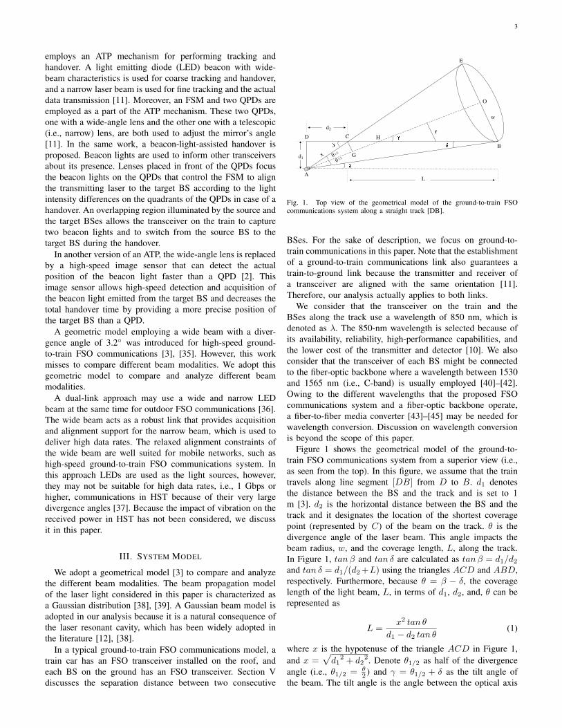
Fig. 1. Top view of the geometrical model of the ground-to-train FSOcommunications system along a straight track [DB].
BSes. For the sake of description, we focus on ground-to-train communications in this paper. Note that the establishmentof a ground-to-train communications link also guarantees atrain-to-ground link because the transmitter and receiver ofa transceiver are aligned with the same orientation [11].Therefore, our analysis actually applies to both links.
We consider that the transceiver on the train and theBSes along the track use a wavelength of 850 nm, which isdenoted as λ. The 850-nm wavelength is selected because ofits availability, reliability, high-performance capabilities, andthe lower cost of the transmitter and detector [10]. We alsoconsider that the transceiver of each BS might be connectedto the fiber-optic backbone where a wavelength between 1530and 1565 nm (i.e., C-band) is usually employed [40]–[42].Owing to the different wavelengths that the proposed FSOcommunications system and a fiber-optic backbone operate,a fiber-to-fiber media converter [43]–[45] may be needed forwavelength conversion. Discussion on wavelength conversionis beyond the scope of this paper.
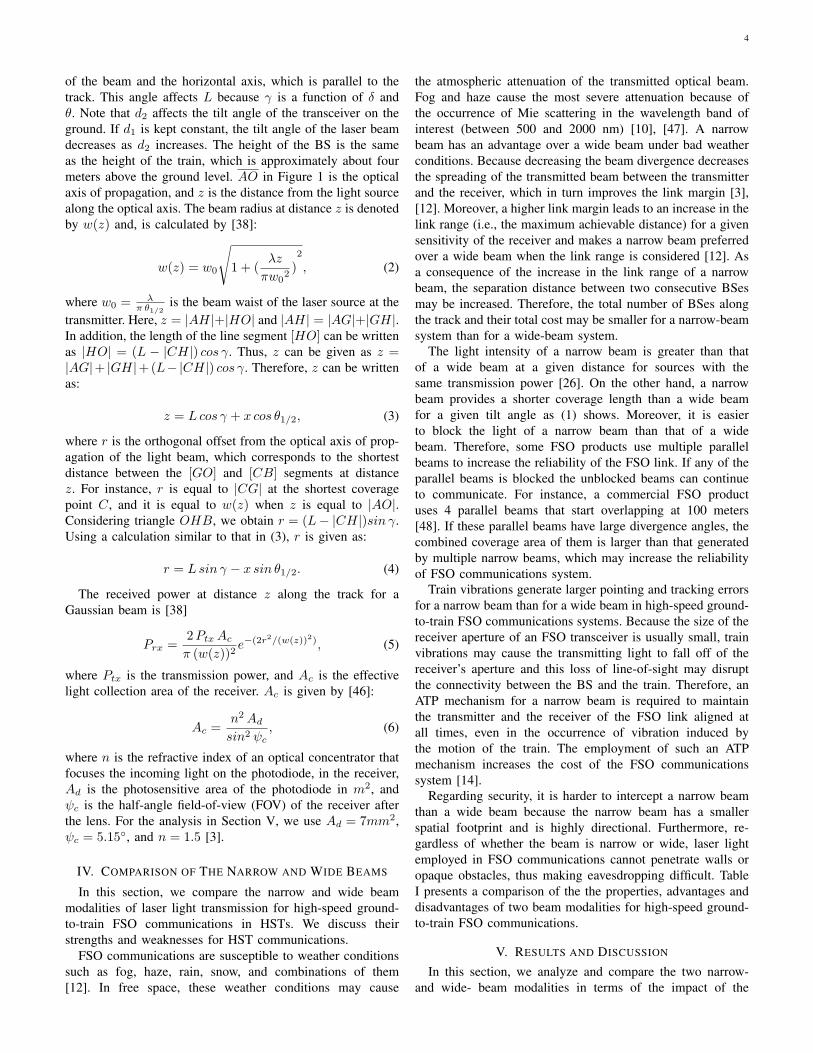
Figure 1 shows the geometrical model of the ground-to-train FSO communications system from a superior view (i.e.,as seen from the top). In this figure, we assume that the traintravels along line segment [DB] from D to B. d1 denotesthe distance between the BS and the track and is set to 1m [3]. d2 is the horizontal distance between the BS and thetrack and it designates the location of the shortest coveragepoint (represented by C) of the beam on the track. θ is thedivergence angle of the laser beam. This angle impacts thebeam radius, w, and the coverage length, L, along the track.In Figure 1, tanβ and tan δ are calculated as tanβ = d1/d2and tan δ = d1/(d2+L) using the triangles ACD and ABD,respectively. Furthermore, because θ = β − δ, the coveragelength of the light beam, L, in terms of d1, d2, and, θ can berepresented as
L =x2 tan θ
d1 − d2 tan θ(1)
where x is the hypotenuse of the triangle ACD in Figure 1,and x =
√d1
2 + d22. Denote θ1/2 as half of the divergence
angle (i.e., θ1/2 = θ2 ) and γ = θ1/2 + δ as the tilt angle of
the beam. The tilt angle is the angle between the optical axis
4
of the beam and the horizontal axis, which is parallel to thetrack. This angle affects L because γ is a function of δ andθ. Note that d2 affects the tilt angle of the transceiver on theground. If d1 is kept constant, the tilt angle of the laser beamdecreases as d2 increases. The height of the BS is the sameas the height of the train, which is approximately about fourmeters above the ground level. AO in Figure 1 is the opticalaxis of propagation, and z is the distance from the light sourcealong the optical axis. The beam radius at distance z is denotedby w(z) and, is calculated by [38]:
w(z) = w0
√
1 + (λz
πw02)2
, (2)
where w0 = λπ θ1/2
is the beam waist of the laser source at thetransmitter. Here, z = |AH|+|HO| and |AH| = |AG|+|GH|.In addition, the length of the line segment [HO] can be writtenas |HO| = (L − |CH|) cos γ. Thus, z can be given as z =|AG|+ |GH|+(L− |CH|) cos γ. Therefore, z can be writtenas:
z = L cos γ + x cos θ1/2, (3)
where r is the orthogonal offset from the optical axis of prop-agation of the light beam, which corresponds to the shortestdistance between the [GO] and [CB] segments at distancez. For instance, r is equal to |CG| at the shortest coveragepoint C, and it is equal to w(z) when z is equal to |AO|.Considering triangle OHB, we obtain r = (L− |CH|)sin γ.Using a calculation similar to that in (3), r is given as:
r = Lsin γ − x sin θ1/2. (4)
The received power at distance z along the track for aGaussian beam is [38]
Prx =2Ptx Ac
π (w(z))2e−(2r2/(w(z))2), (5)
where Ptx is the transmission power, and Ac is the effectivelight collection area of the receiver. Ac is given by [46]:
Ac =n2 Ad
sin2 ψc, (6)
where n is the refractive index of an optical concentrator thatfocuses the incoming light on the photodiode, in the receiver,Ad is the photosensitive area of the photodiode in m2, andψc is the half-angle field-of-view (FOV) of the receiver afterthe lens. For the analysis in Section V, we use Ad = 7mm2,ψc = 5.15◦, and n = 1.5 [3].
IV. COMPARISON OF THE NARROW AND WIDE BEAMS
In this section, we compare the narrow and wide beammodalities of laser light transmission for high-speed ground-to-train FSO communications in HSTs. We discuss theirstrengths and weaknesses for HST communications.
FSO communications are susceptible to weather conditionssuch as fog, haze, rain, snow, and combinations of them[12]. In free space, these weather conditions may cause
the atmospheric attenuation of the transmitted optical beam.Fog and haze cause the most severe attenuation because ofthe occurrence of Mie scattering in the wavelength band ofinterest (between 500 and 2000 nm) [10], [47]. A narrowbeam has an advantage over a wide beam under bad weatherconditions. Because decreasing the beam divergence decreasesthe spreading of the transmitted beam between the transmitterand the receiver, which in turn improves the link margin [3],[12]. Moreover, a higher link margin leads to an increase in thelink range (i.e., the maximum achievable distance) for a givensensitivity of the receiver and makes a narrow beam preferredover a wide beam when the link range is considered [12]. Asa consequence of the increase in the link range of a narrowbeam, the separation distance between two consecutive BSesmay be increased. Therefore, the total number of BSes alongthe track and their total cost may be smaller for a narrow-beamsystem than for a wide-beam system.
The light intensity of a narrow beam is greater than thatof a wide beam at a given distance for sources with thesame transmission power [26]. On the other hand, a narrowbeam provides a shorter coverage length than a wide beamfor a given tilt angle as (1) shows. Moreover, it is easierto block the light of a narrow beam than that of a widebeam. Therefore, some FSO products use multiple parallelbeams to increase the reliability of the FSO link. If any of theparallel beams is blocked the unblocked beams can continueto communicate. For instance, a commercial FSO productuses 4 parallel beams that start overlapping at 100 meters[48]. If these parallel beams have large divergence angles, thecombined coverage area of them is larger than that generatedby multiple narrow beams, which may increase the reliabilityof FSO communications system.
Train vibrations generate larger pointing and tracking errorsfor a narrow beam than for a wide beam in high-speed ground-to-train FSO communications systems. Because the size of thereceiver aperture of an FSO transceiver is usually small, trainvibrations may cause the transmitting light to fall off of thereceiver’s aperture and this loss of line-of-sight may disruptthe connectivity between the BS and the train. Therefore, anATP mechanism for a narrow beam is required to maintainthe transmitter and the receiver of the FSO link aligned atall times, even in the occurrence of vibration induced bythe motion of the train. The employment of such an ATPmechanism increases the cost of the FSO communicationssystem [14].
Regarding security, it is harder to intercept a narrow beamthan a wide beam because the narrow beam has a smallerspatial footprint and is highly directional. Furthermore, re-gardless of whether the beam is narrow or wide, laser lightemployed in FSO communications cannot penetrate walls oropaque obstacles, thus making eavesdropping difficult. TableI presents a comparison of the the properties, advantages anddisadvantages of two beam modalities for high-speed ground-to-train FSO communications.
V. RESULTS AND DISCUSSION
In this section, we analyze and compare the two narrow-and wide- beam modalities in terms of the impact of the
5
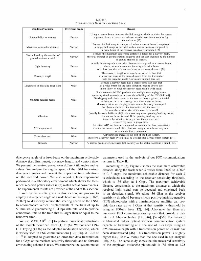
TABLE ICOMPARISON OF NARROW AND WIDE BEAM
Condition/Scenario Preferred beam Reason
Susceptibility to weather NarrowUsing a narrow beam improves the link margin, which provides the system
a greater chance to overcome adverse weather conditions such as fog,rain and snow [12].
Maximum achievable distance NarrowBecause the link margin is improved when a narrow beam is employed,
a longer link range is provided with a narrow beam as compared toa wide beam at the receiver sensitivity threshold [12].
Cost induced by the number ofground stations needed Narrow
Because the maximum achievable distance is larger for a narrow beam,the total number of ground stations required and the cost incurred by the number
of ground stations is smaller.
Light intensity NarrowA wide beam expands more with distance as compared to a narrow beam,
which, in turn, causes the intensity of a wide beamto be less than that of a narrow beam at the same distance [26].
Coverage length WideThe coverage length of a wide beam is larger than that
of a narrow beam at the same distance from the transmitterwith the same tilt angle. Our results support this fact.
Likelihood of blocking laser light WideBecause a narrow beam has a smaller spot size than thatof a wide beam for the same distance, opaque objects aremore likely to block the narrow beam than a wide beam.
Multiple parallel beams Wide
Some commercial FSO products use multiple overlapping beamsoperating simultaneously to increase the reliability of the FSO link [48].
Overlapping wide laser beams at the receiver have a greater potentialto increase the total coverage area than a narrow beam.
Moreover, wider overlapping beams cannot be easily interruptedby obstacles between the transmitter and the receiver.
Vibration Wide
Because the aperture size of the receiver is small(usually between 1-40 cm [49]), vibrations may cause pointing/tracking errors,
if a narrow beam is used. If the pointing/tracking errorinduced by vibration is larger than the aperture size,
connectivity may be jeopardized.
ATP requirement WideAn active ATP mechanism is required to maintain the link connectivityif a narrow beam is used [14]. However, using a wide beam may relax
or eliminate this requirement.
Transceiver cost Wide ATP hardware increases the cost of the FSO system.Therefore, a narrow-beam system may be costlier than a wide-beam system [14].
Security Narrow A narrow beam offers increased link security as the spatial footprint is small [50].
divergence angle of a laser beam on the maximum achievabledistance (i.e., link range), coverage length, and contact time.We present the received power over different tilt angles and d2values. We analyze the angular speed of the FSM for variousdivergence angles and present the impact of train vibrationson the received power. We also report a laser experimentperformed in a laboratory environment which shows the theo-retical received power values in (5) match actual power values.The experimental results are provided at the end of this section.
Based on the results given in this section, we propose toemploy a divergence angle of a wide beam in the range [0.07◦,2.002◦] to drastically reduce the steering speed of the FSM,to accommodate vertical displacements of the train of up to50 mm while guaranteeing a 1-Gbps data rate, and to provideconnection time to the train that is larger than or equal to thehandover time.
We use MATLAB! [51] to perform numerical evaluationsof the models described from (1) to (6). We consider ON–OFF keying (OOK) as the adopted modulation scheme, whichis widely used in FSO communications [12], [26]. A BER of10−9 is adopted to guarantee an error-free data transmissionfor 1 Gbps at the receiver sensitivity threshold and no forwarderror coding scheme is used. We summarize the system model
parameters used in the analysis of our FSO communicationssystem in Table II.
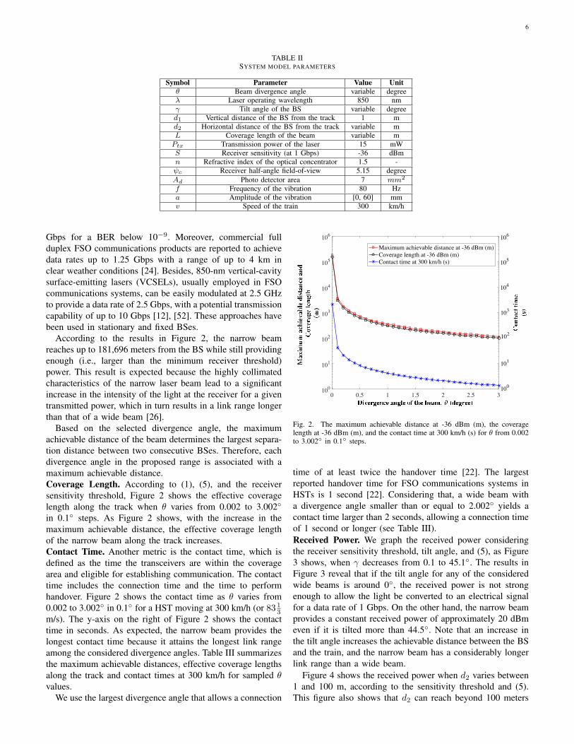
According to (5), Figure 2 shows the maximum achievabledistance along the track when θ varies from 0.002 to 3.002◦in 0.1◦ steps; the maximum achievable distance for each θis calculated according to the receiver sensitivity threshold,which is -36 dBm at 1 Gbps. The maximum achievabledistance corresponds to the maximum distance at which thereceived light signal can be decoded and converted backto an electrical signal. We adopt -36 dBm as the receiversensitivity threshold because silicon positive-intrinsic-negative(PIN) photodiodes with a transimpedance amplifier can pro-vide data rates up to 1 Gbps at that sensitivity threshold byusing an 850-nm laser [12], [24]. Also note that there arenumerous FSO communications systems that provide a datarate of 1 Gbps or higher [12], [46], [52]–[56]. For instance,a fabricated indoor optical wireless communication systemcapable of transmitting at a line rate of 1.25 Gbps using an825-nm-wavelength with a transmission power of 25 mW hasbeen demonstrated [46]. This transmission power is slightlyhigher (i.e., 10 mW more) than the one used in our analysis[46], [53]. The same study shows that the measured sensitivityof the employed avalanche photodiode is -35 dBm at 1.25
6
TABLE IISYSTEM MODEL PARAMETERS
Symbol Parameter Value Unitθ Beam divergence angle variable degreeλ Laser operating wavelength 850 nmγ Tilt angle of the BS variable degreed1 Vertical distance of the BS from the track 1 md2 Horizontal distance of the BS from the track variable mL Coverage length of the beam variable mPtx Transmission power of the laser 15 mWS Receiver sensitivity (at 1 Gbps) -36 dBmn Refractive index of the optical concentrator 1.5 -ψc Receiver half-angle field-of-view 5.15 degreeAd Photo detector area 7 mm2
f Frequency of the vibration 80 Hza Amplitude of the vibration [0, 60] mmv Speed of the train 300 km/h
Gbps for a BER below 10−9. Moreover, commercial fullduplex FSO communications products are reported to achievedata rates up to 1.25 Gbps with a range of up to 4 km inclear weather conditions [24]. Besides, 850-nm vertical-cavitysurface-emitting lasers (VCSELs), usually employed in FSOcommunications systems, can be easily modulated at 2.5 GHzto provide a data rate of 2.5 Gbps, with a potential transmissioncapability of up to 10 Gbps [12], [52]. These approaches havebeen used in stationary and fixed BSes.
According to the results in Figure 2, the narrow beamreaches up to 181,696 meters from the BS while still providingenough (i.e., larger than the minimum receiver threshold)power. This result is expected because the highly collimatedcharacteristics of the narrow laser beam lead to a significantincrease in the intensity of the light at the receiver for a giventransmitted power, which in turn results in a link range longerthan that of a wide beam [26].
Based on the selected divergence angle, the maximumachievable distance of the beam determines the largest separa-tion distance between two consecutive BSes. Therefore, eachdivergence angle in the proposed range is associated with amaximum achievable distance.Coverage Length. According to (1), (5), and the receiversensitivity threshold, Figure 2 shows the effective coveragelength along the track when θ varies from 0.002 to 3.002◦in 0.1◦ steps. As Figure 2 shows, with the increase in themaximum achievable distance, the effective coverage lengthof the narrow beam along the track increases.Contact Time. Another metric is the contact time, which isdefined as the time the transceivers are within the coveragearea and eligible for establishing communication. The contacttime includes the connection time and the time to performhandover. Figure 2 shows the contact time as θ varies from0.002 to 3.002◦ in 0.1◦ for a HST moving at 300 km/h (or 83 1
3m/s). The y-axis on the right of Figure 2 shows the contacttime in seconds. As expected, the narrow beam provides thelongest contact time because it attains the longest link rangeamong the considered divergence angles. Table III summarizesthe maximum achievable distances, effective coverage lengthsalong the track and contact times at 300 km/h for sampled θvalues.
We use the largest divergence angle that allows a connection
0 0.5 1 1.5 2 2.5 3100
101
102
103
104
105
106
Maximum achievable distance at -36 dBm (m)Coverage length at -36 dBm (m)Contact time at 300 km/h (s)
106
100
101
102
103
104
105
Fig. 2. The maximum achievable distance at -36 dBm (m), the coveragelength at -36 dBm (m), and the contact time at 300 km/h (s) for θ from 0.002to 3.002◦ in 0.1◦ steps.
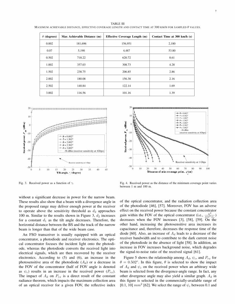
time of at least twice the handover time [22]. The largestreported handover time for FSO communications systems inHSTs is 1 second [22]. Considering that, a wide beam witha divergence angle smaller than or equal to 2.002◦ yields acontact time larger than 2 seconds, allowing a connection timeof 1 second or longer (see Table III).Received Power. We graph the received power consideringthe receiver sensitivity threshold, tilt angle, and (5), as Figure3 shows, when γ decreases from 0.1 to 45.1◦. The results inFigure 3 reveal that if the tilt angle for any of the consideredwide beams is around 0◦, the received power is not strongenough to allow the light be converted to an electrical signalfor a data rate of 1 Gbps. On the other hand, the narrow beamprovides a constant received power of approximately 20 dBmeven if it is tilted more than 44.5◦. Note that an increase inthe tilt angle increases the achievable distance between the BSand the train, and the narrow beam has a considerably longerlink range than a wide beam.
Figure 4 shows the received power when d2 varies between1 and 100 m, according to the sensitivity threshold and (5).This figure also shows that d2 can reach beyond 100 meters
7
TABLE IIIMAXIMUM ACHIEVABLE DISTANCE, EFFECTIVE COVERAGE LENGTH AND CONTACT TIME AT 300 KM/H FOR SAMPLED θ VALUES.
θ (degrees) Max Achievable Distance (m) Effective Coverage Length (m) Contact Time at 300 km/h (s)
0.002 181,696 156,951 2,180
0.07 5,190 4,487 53.80
0.502 718.22 620.72 8.61
1.002 357.03 308.73 4.28
1.502 238.75 206.85 2.86
2.002 180.08 156.38 2.16
2.502 140.84 122.14 1.69
3.002 116.56 101.16 1.39
0 5 10 15 20 25 30 35 40 45-50
-40
-30
-20
-10
0
10
20
= 0.002° = 1.502° = 2.002° = 2.502° = 3.002°
-36 dBm (receiver sensitivity at 1Gbps)
Receiver sensitivity at 1 Gbps
Fig. 3. Received power as a function of γ.
without a significant decrease in power for the narrow beam.These results also show that a beam with a divergence angle inthe proposed range may deliver enough power at the receiverto operate above the sensitivity threshold as d2 approaches100 m. Similar to the results shown in Figure 3, d2 increasesfor a constant d1 as the tilt angle decreases. Therefore, thehorizontal distance between the BS and the track of the narrowbeam is longer than that of the wide beam case.
An FSO transceiver is usually equipped with an opticalconcentrator, a photodiode and receiver electronics. The opti-cal concentrator focuses the incident light onto the photodi-ode, whereas the photodiode converts the received light intoelectrical signals, which are then recovered by the receiverelectronics. According to (5) and (6), an increase in thephotosensitive area of the photodiode (Ad) or a decrease inthe FOV of the concentrator (half of FOV angle is denotedas ψc) results in an increase in the received power (Prx).The impact of Ad on Prx is a direct result of the constantradiance theorem, which impacts the maximum collection areaof an optical receiver for a given FOV, the reflective index
0 10 20 30 40 50 60 70 80 90 100-50
-40
-30
-20
-10
0
10
20
= 0.002° = 0.502° = 1.002° = 1.502° = 2.002° = 2.502° = 3.002°
-36 dBm(receiver sensitivity at 1Gbps)
Receiver sensitivity at 1 Gbps
Fig. 4. Received power as the distance of the minimum coverage point variesbetween 1 m and 100 m.
of the optical concentrator, and the radiation collection areaof the photodiode [46], [57]. Moreover, FOV has an adverseeffect on the received power because the constant concentratorgain within the FOV of the optical concentrator (i.e., n2
sin2 ψc)
decreases when the FOV increases [3], [58], [59]. On theother hand, increasing the photosensitive area increases itscapacitance and, therefore, decreases the response time of thediode [60]. Also, an increase of Ad leads to a decrease of thereceiver bandwidth and to contribute to the dark current noiseof the photodiode in the absence of light [58]. In addition, anincrease in FOV increases background noise, which degradesthe signal-to-noise ratio of the received signal [61].
Figure 5 shows the relationship among Ad, ψc, and Prx forθ = 0.502◦. In this figure, θ is selected to show the impactof Ad and ψc on the received power when an arbitrary widebeam is selected from the divergence-angle range. In fact, anyother divergence angle may also yield a similar graph. Ad inthis figure is selected in the commercially-available range of[0.1, 10] mm2 [62]. We select the range of ψc between 0.1 and
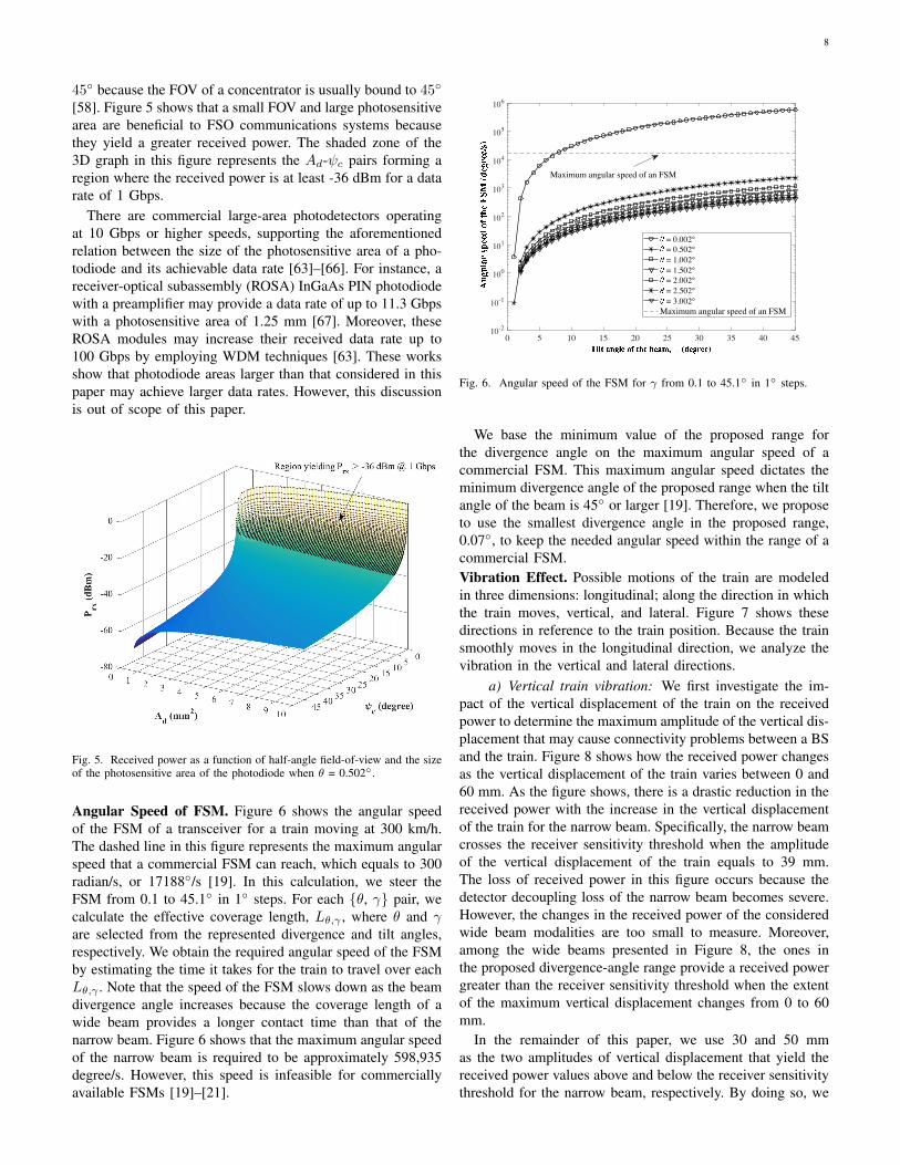
8
45◦ because the FOV of a concentrator is usually bound to 45◦
[58]. Figure 5 shows that a small FOV and large photosensitivearea are beneficial to FSO communications systems becausethey yield a greater received power. The shaded zone of the3D graph in this figure represents the Ad-ψc pairs forming aregion where the received power is at least -36 dBm for a datarate of 1 Gbps.
There are commercial large-area photodetectors operatingat 10 Gbps or higher speeds, supporting the aforementionedrelation between the size of the photosensitive area of a pho-todiode and its achievable data rate [63]–[66]. For instance, areceiver-optical subassembly (ROSA) InGaAs PIN photodiodewith a preamplifier may provide a data rate of up to 11.3 Gbpswith a photosensitive area of 1.25 mm [67]. Moreover, theseROSA modules may increase their received data rate up to100 Gbps by employing WDM techniques [63]. These worksshow that photodiode areas larger than that considered in thispaper may achieve larger data rates. However, this discussionis out of scope of this paper.
Fig. 5. Received power as a function of half-angle field-of-view and the sizeof the photosensitive area of the photodiode when θ = 0.502◦.
Angular Speed of FSM. Figure 6 shows the angular speedof the FSM of a transceiver for a train moving at 300 km/h.The dashed line in this figure represents the maximum angularspeed that a commercial FSM can reach, which equals to 300radian/s, or 17188◦/s [19]. In this calculation, we steer theFSM from 0.1 to 45.1◦ in 1◦ steps. For each {θ, γ} pair, wecalculate the effective coverage length, Lθ,γ , where θ and γare selected from the represented divergence and tilt angles,respectively. We obtain the required angular speed of the FSMby estimating the time it takes for the train to travel over eachLθ,γ . Note that the speed of the FSM slows down as the beamdivergence angle increases because the coverage length of awide beam provides a longer contact time than that of thenarrow beam. Figure 6 shows that the maximum angular speedof the narrow beam is required to be approximately 598,935degree/s. However, this speed is infeasible for commerciallyavailable FSMs [19]–[21].
0 5 10 15 20 25 30 35 40 4510-2
10-1
100
101
102
103
104
105
106
= 0.002° = 0.502° = 1.002° = 1.502° = 2.002° = 2.502° = 3.002°
Maximum angular speed of an FSM
Maximum angular speed of an FSM
Fig. 6. Angular speed of the FSM for γ from 0.1 to 45.1◦ in 1◦ steps.
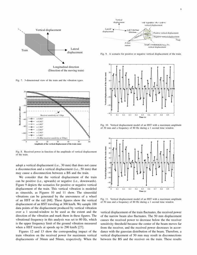
We base the minimum value of the proposed range forthe divergence angle on the maximum angular speed of acommercial FSM. This maximum angular speed dictates theminimum divergence angle of the proposed range when the tiltangle of the beam is 45◦ or larger [19]. Therefore, we proposeto use the smallest divergence angle in the proposed range,0.07◦, to keep the needed angular speed within the range of acommercial FSM.Vibration Effect. Possible motions of the train are modeledin three dimensions: longitudinal; along the direction in whichthe train moves, vertical, and lateral. Figure 7 shows thesedirections in reference to the train position. Because the trainsmoothly moves in the longitudinal direction, we analyze thevibration in the vertical and lateral directions.
a) Vertical train vibration: We first investigate the im-pact of the vertical displacement of the train on the receivedpower to determine the maximum amplitude of the vertical dis-placement that may cause connectivity problems between a BSand the train. Figure 8 shows how the received power changesas the vertical displacement of the train varies between 0 and60 mm. As the figure shows, there is a drastic reduction in thereceived power with the increase in the vertical displacementof the train for the narrow beam. Specifically, the narrow beamcrosses the receiver sensitivity threshold when the amplitudeof the vertical displacement of the train equals to 39 mm.The loss of received power in this figure occurs because thedetector decoupling loss of the narrow beam becomes severe.However, the changes in the received power of the consideredwide beam modalities are too small to measure. Moreover,among the wide beams presented in Figure 8, the ones inthe proposed divergence-angle range provide a received powergreater than the receiver sensitivity threshold when the extentof the maximum vertical displacement changes from 0 to 60mm.
In the remainder of this paper, we use 30 and 50 mmas the two amplitudes of vertical displacement that yield thereceived power values above and below the receiver sensitivitythreshold for the narrow beam, respectively. By doing so, we
9
Vertical displacement
Lateral displacement
Longitudinal direction(Direction of the moving train)
Train
Fig. 7. 3-dimensional view of the train and the vibration types.
0 10 20 30 40 50 60−120
−100
−80
−60
−40
−20
0
20
Amplitude of the vertical displacement of the train (mm)
Rec
eive
d po
wer
(dBm
)
= 0.002° = 0.502° = 1.002° = 1.502° = 2.002° = 2.502° = 3.002° −36 dBm (receiver sensitivity at 1Gbps)
Receiver sensitivity at 1 Gbps
Fig. 8. Received power in function of the amplitude of vertical displacementof the train.
adopt a vertical displacement (i.e., 30 mm) that does not causea disconnection and a vertical displacement (i.e., 50 mm) thatmay cause a disconnection between a BS and the train.
We consider that the vertical displacement of the traincan be positive (i.e., upwards) or negative (i.e., downwards).Figure 9 depicts the scenarios for positive or negative verticaldisplacement of the train. This vertical vibration is modeledas sinusoids, as Figures 10 and 11 show. The sinusoidalvibrations can be generated by the unevenness of a wheelof an HST or the rail [68]. These figures show the verticaldisplacement of an HST traveling at 300 km/h. We sample 100data points of the displacement produced by vertical vibrationover a 1 second-window to be used as the extent and thedirection of the vibration and mark them in these figures. Thevibrational frequency in this analysis was set to 80 Hz, whichis the upper frequency limit of the ground vibration measuredwhen a HST travels at speeds up to 290 km/h [27].
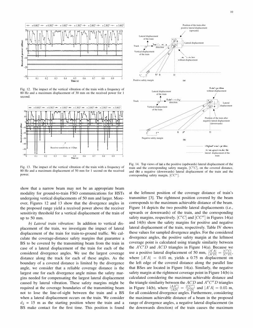
Figures 12 and 13 show the corresponding impact of thetrain vibration on the received power for maximum verticaldisplacements of 30mm and 50mm, respectively. When the
Positive vertical displacement
Negative vertical displacement
directionLateral
displacement
Vertical displacement
A base station
vertical displacement
vertical displacement
Fig. 9. A scenario for positive or negative vertical displacement of the train.
0 0.1 0.2 0.3 0.4 0.5 0.6 0.7 0.8 0.9 1−30
−20
−10
0
10
20
30
Time (s)
Ver
tical
disp
lace
men
t of t
he tr
ain
(mm
)
Fig. 10. Vertical displacement model of an HST with a maximum amplitudeof 30 mm and a frequency of 80 Hz during a 1 second time window.
0 0.1 0.2 0.3 0.4 0.5 0.6 0.7 0.8 0.9 1−50
−40
−30
−20
−10
0
10
20
30
40
50
Time (s)
Ver
tical
disp
lace
men
t of t
he tr
ain
(mm
)
Fig. 11. Vertical displacement model of an HST with a maximum amplitudeof 50 mm and a frequency of 80 Hz during a 1 second time window.
vertical displacement of the train fluctuates, the received powerof the narrow beam also fluctuates. The 50 mm displacementcauses the received power to decrease below the the receiversensitivity threshold because the center of the beam moves farfrom the receiver, and the received power decreases in accor-dance with the gaussian distribution of the beam. Therefore, avertical displacement of 50 mm may result in disconnectionsbetween the BS and the receiver on the train. These results
10
0 0.1 0.2 0.3 0.4 0.5 0.6 0.7 0.8 0.9 1−30
−20
−10
0
10
20
Time (s)
Rec
eive
d po
wer
(dB
m)
= 0.002° = 0.502° = 1.002° = 1.502° = 2.002° = 2.502° = 3.002°
Fig. 12. The impact of the vertical vibration of the train with a frequency of80 Hz and a maximum displacement of 30 mm on the received power for 1second.
0 0.1 0.2 0.3 0.4 0.5 0.6 0.7 0.8 0.9 1−60
−50
−40
−30
−20
−10
0
10
20
Time (s)
Rec
eive
d po
wer
(dBm
)
= 0.002° = 0.502° = 1.002° = 1.502° = 2.002° = 2.502° = 3.002°
Receiver sensitivity at 1 Gbps
Fig. 13. The impact of the vertical vibration of the train with a frequency of80 Hz and a maximum displacement of 50 mm for 1 second on the receivedpower.
show that a narrow beam may not be an appropriate beammodality for ground-to-train FSO communications for HSTsundergoing vertical displacements of 50 mm and larger. More-over, Figures 12 and 13 show that the divergence angles inthe proposed range yield a received power above the receiversensitivity threshold for a vertical displacement of the train ofup to 50 mm.
b) Lateral train vibration: In addition to vertical dis-placement of the train, we investigate the impact of lateraldisplacement of the train for train-to-ground traffic. We cal-culate the coverage-distance safety margins that guarantee aBS to be covered by the transmitting beam from the train incase of a lateral displacement of the train for each of theconsidered divergence angles. We use the largest coveragedistance along the track for each of these angles. As theboundary of a covered distance is limited by the divergenceangle, we consider that a reliable coverage distance is thelargest one for each divergence angle minus the safety mar-gins needed for compensating the largest lateral displacementcaused by lateral vibration. These safety margins might berequired at the coverage boundaries of the transmitting beamnot to lose the line-of-sight between the train and a BSwhen a lateral displacement occurs on the train. We considerd2 = 15 m as the starting position where the train and aBS make contact for the first time. This position is found
C B
Positive safety margin (a)
(b)
lateral displacement of the train
Track
without displacement
Position of the train after positive lateral displacement
(upwards)
C B
Track
without displacement
Position of the train after negative lateral displacement
(downwards)
Negative safety margin
Lateral displacement of the train
direction
Vertical displacement of the train
Lateral displacement of the train
direction
Vertical displacement of the train
Lateral displacement
Lateral displacement
A
A
D
D
Fig. 14. Top views of (a) a the positive (updwards) lateral displacement of thetrain and the corresponding safety margin, [C′C], on the covered distance,and (b) a negative (downwards) lateral displacement of the train and thecorresponding safety margin, [CC”].
at the leftmost position of the coverage distance of train’stransmitter [3]. The rightmost position covered by the beamcorresponds to the maximum achievable distance of the beam.Figure 14 depicts the two possible lateral displacements (i.e.,upwards or downwards) of the train, and the correspondingsafety margins, respectively. [C ′C] and [CC ′′] in Figures 14(a)and 14(b) show the safety margins for positive and negativelateral displacement of the train, respectively. Table IV showsthese values for sampled divergence angles. For the considereddivergence angles, the positive safety margin at the leftmostcoverage point is calculated using triangle similarity betweenthe A′C ′D and ACD triangles in Figure 14(a). Because weuse a positive lateral displacement of 50 mm, |A′A|
|A′D| =|C′C||C′D| ,
where |A′A| = 0.05 m, yields a 0.75 m displacement onthe left edge of the covered distance along the parallel linethat BSes are located in Figure 14(a). Similarly, the negativesafety margin at the rightmost coverage point in Figure 14(b) iscalculated considering the maximum achievable distance andthe triangle similarity between the ACD and A′′C ′′D trianglesin Figure 14(b), where |AA′′|
|AD| = |CC′′||CD| and |A′A| = 0.05 m,
for all considered divergence angles. Furthermore, consideringthe maximum achievable distance of a beam in the proposedrange of divergence angles, a negative lateral displacement (inthe downwards direction) of the train causes the maximum
11
coverage point of the 0.07◦ beam to be adjusted to 4,931 m,which yields a 259-m safety margin. In other words, a 50-mm lateral displacement of the train would leave 259 m ofthe coverage length uncovered when the divergence angle isselected as 0.07◦. Therefore, we exclude that length from themaximum achievable distance. Similarly, the same negativelateral displacement causes the beam with a divergence angleof 2.002◦ to displace about 9 meters. Therefore, a lateraldisplacement of 50 mm defines safety margins (i.e., 0.75 and[9, 259] m, respectively) for the beams in the proposed rangesuch that the train and corresponding BS keep line-of-sightdespite the occurrence of lateral vibrations.
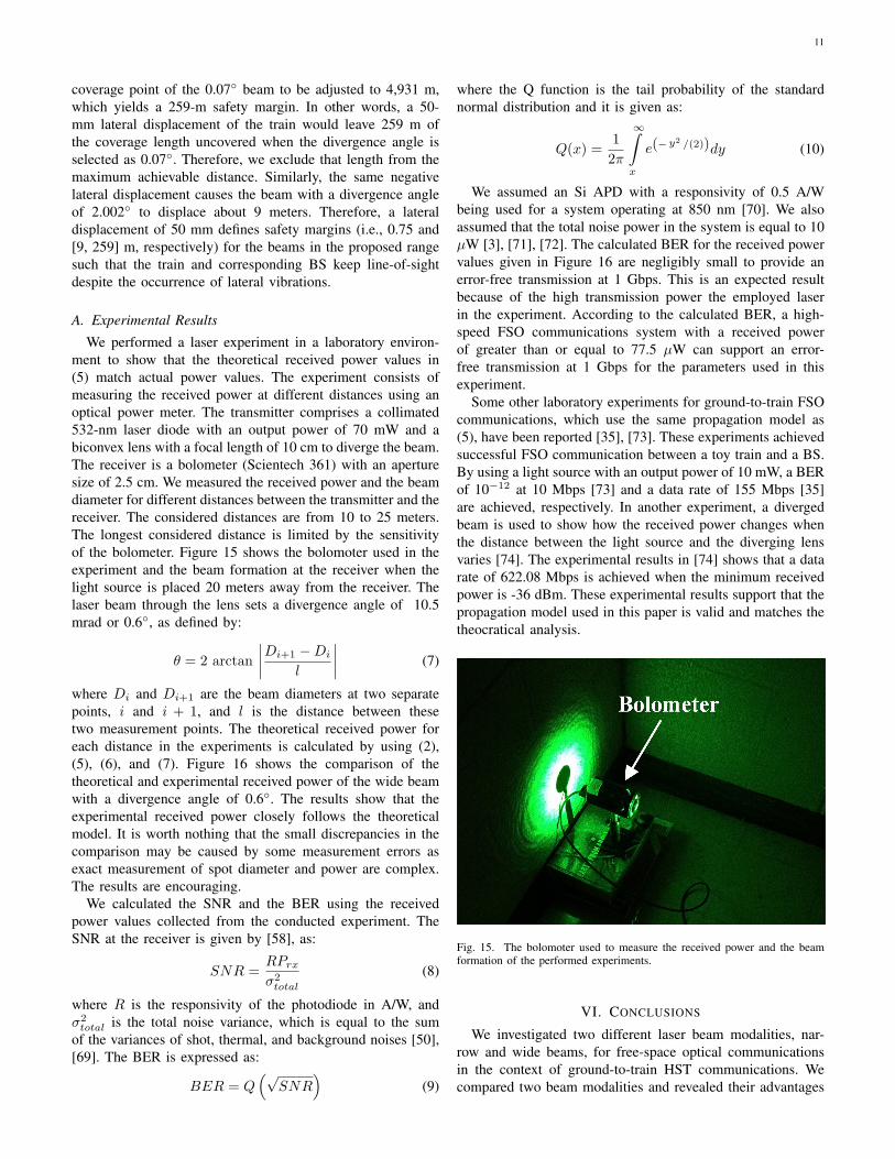
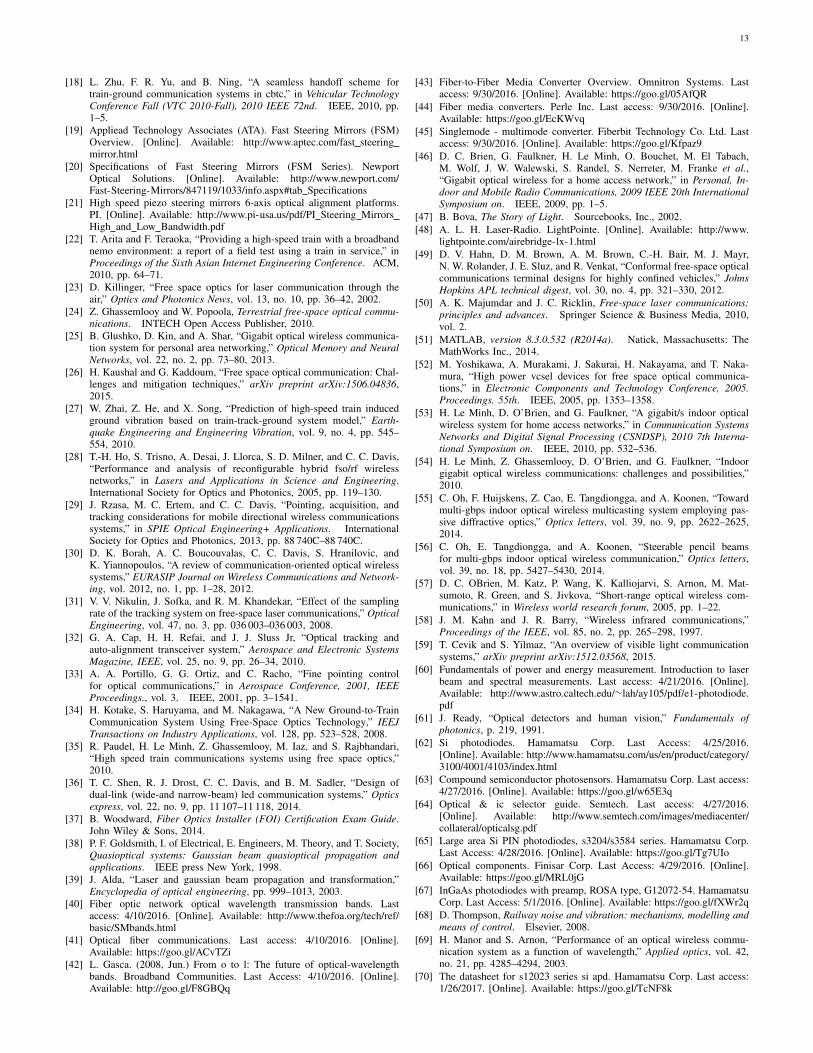
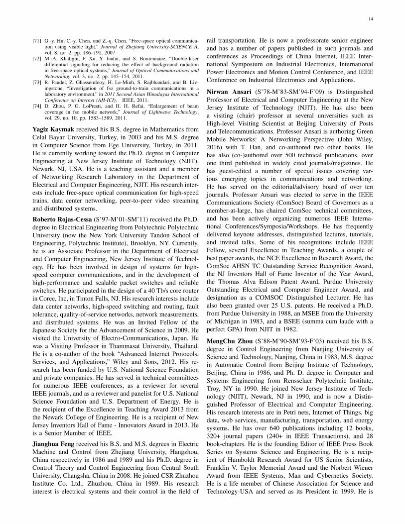
A. Experimental ResultsWe performed a laser experiment in a laboratory environ-
ment to show that the theoretical received power values in(5) match actual power values. The experiment consists ofmeasuring the received power at different distances using anoptical power meter. The transmitter comprises a collimated532-nm laser diode with an output power of 70 mW and abiconvex lens with a focal length of 10 cm to diverge the beam.The receiver is a bolometer (Scientech 361) with an aperturesize of 2.5 cm. We measured the received power and the beamdiameter for different distances between the transmitter and thereceiver. The considered distances are from 10 to 25 meters.The longest considered distance is limited by the sensitivityof the bolometer. Figure 15 shows the bolomoter used in theexperiment and the beam formation at the receiver when thelight source is placed 20 meters away from the receiver. Thelaser beam through the lens sets a divergence angle of 10.5mrad or 0.6◦, as defined by:
θ = 2 arctan
∣∣∣∣Di+1 −Di
l
∣∣∣∣ (7)
where Di and Di+1 are the beam diameters at two separatepoints, i and i + 1, and l is the distance between thesetwo measurement points. The theoretical received power foreach distance in the experiments is calculated by using (2),(5), (6), and (7). Figure 16 shows the comparison of thetheoretical and experimental received power of the wide beamwith a divergence angle of 0.6◦. The results show that theexperimental received power closely follows the theoreticalmodel. It is worth nothing that the small discrepancies in thecomparison may be caused by some measurement errors asexact measurement of spot diameter and power are complex.The results are encouraging.
We calculated the SNR and the BER using the receivedpower values collected from the conducted experiment. TheSNR at the receiver is given by [58], as:
SNR =RPrx
σ2total
(8)
where R is the responsivity of the photodiode in A/W, andσ2total is the total noise variance, which is equal to the sum
of the variances of shot, thermal, and background noises [50],[69]. The BER is expressed as:
BER = Q(√
SNR)
(9)
where the Q function is the tail probability of the standardnormal distribution and it is given as:
Q(x) =1
2π
∞∫
x
e(− y2 /(2))dy (10)
We assumed an Si APD with a responsivity of 0.5 A/Wbeing used for a system operating at 850 nm [70]. We alsoassumed that the total noise power in the system is equal to 10µW [3], [71], [72]. The calculated BER for the received powervalues given in Figure 16 are negligibly small to provide anerror-free transmission at 1 Gbps. This is an expected resultbecause of the high transmission power the employed laserin the experiment. According to the calculated BER, a high-speed FSO communications system with a received powerof greater than or equal to 77.5 µW can support an error-free transmission at 1 Gbps for the parameters used in thisexperiment.
Some other laboratory experiments for ground-to-train FSOcommunications, which use the same propagation model as(5), have been reported [35], [73]. These experiments achievedsuccessful FSO communication between a toy train and a BS.By using a light source with an output power of 10 mW, a BERof 10−12 at 10 Mbps [73] and a data rate of 155 Mbps [35]are achieved, respectively. In another experiment, a divergedbeam is used to show how the received power changes whenthe distance between the light source and the diverging lensvaries [74]. The experimental results in [74] shows that a datarate of 622.08 Mbps is achieved when the minimum receivedpower is -36 dBm. These experimental results support that thepropagation model used in this paper is valid and matches thetheocratical analysis.
Fig. 15. The bolomoter used to measure the received power and the beamformation of the performed experiments.
VI. CONCLUSIONS
We investigated two different laser beam modalities, nar-row and wide beams, for free-space optical communicationsin the context of ground-to-train HST communications. Wecompared two beam modalities and revealed their advantages
12
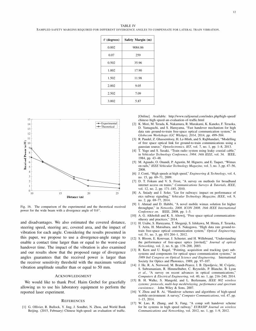
TABLE IVSAMPLED SAFETY MARGINS REQUIRED FOR DIFFERENT DIVERGENCE ANGLES TO COMPENSATE FOR LATERAL TRAIN VIBRATION.
θ (degrees) Safety Margin (m)
0.002 9084.86
0.07 259
0.502 35.96
1.002 17.90
1.502 11.98
2.002 9.05
2.502 7.09
3.002 5.87
10 15 20 250123456789
101112131415
ExperimentalTheoretical
Fig. 16. The comparison of the experimental and the theoretical receivedpower for the wide beam with a divergence angle of 0.6◦.
and disadvantages. We also estimated the covered distance,steering speed, steering arc, covered area, and the impact ofvibration for each angle. Considering the results presented inthis paper, we propose to use a divergence-angle range toenable a contact time larger than or equal to the worst-casehandover time. The impact of the vibration is also examinedand our results show that the proposed range of divergenceangles guarantees that the received power is larger thanthe receiver sensitivity threshold with the maximum verticalvibration amplitude smaller than or equal to 50 mm.
ACKNOWLEDGMENT
We would like to thank Prof. Haim Grebel for gracefullyallowing us to use his laboratory equipment to perform thereported laser experiment.
REFERENCES
[1] G. Ollivier, R. Bullock, Y. Jing, J. Sondhri, N. Zhou, and World BankBeijing. (2015, February) Chinese high-speed: an evaluation of traffic.
[Online]. Available: http://www.railjournal.com/index.php/high-speed/chinese-high-speed-an-evaluation-of-traffic.html
[2] K. Mori, M. Terada, K. Nakamura, R. Murakami, K. Kaneko, F. Teraoka,D. Yamaguchi, and S. Haruyama, “Fast handover mechanism for highdata rate ground-to-train free-space optical communication system,” inGlobecom Workshops (GC Wkshps), 2014, 2014, pp. 499–504.
[3] R. Paudel, Z. Ghassemlooy, H. Le-Minh, and S. Rajbhandari, “Modellingof free space optical link for ground-to-train communications using agaussian source,” Optoelectronics, IET, vol. 7, no. 1, pp. 1–8, 2013.
[4] T. Yuge and S. Sasaki, “Train radio system using leaky coaxial cable,”in Vehicular Technology Conference, 1984. 34th IEEE, vol. 34. IEEE,1984, pp. 43–48.
[5] M. Aguado, O. Onandi, P. Agustin, M. Higuero, and E. Taquet, “Wimaxon rails,” IEEE Vehicular Technology Magazine, vol. 3, no. 3, pp. 47–56,2008.
[6] J. Conti, “High speeds at high speed,” Engineering & Technology, vol. 4,no. 15, pp. 69–71, 2009.
[7] D. T. Fokum and V. S. Frost, “A survey on methods for broadbandinternet access on trains,” Communications Surveys & Tutorials, IEEE,vol. 12, no. 2, pp. 171–185, 2010.
[8] A. Sniady and J. Soler, “Lte for railways: impact on performance ofetcs railway signaling,” Vehicular Technology Magazine, IEEE, vol. 9,no. 2, pp. 69–77, 2014.
[9] I. Ahmad and D. Habibi, “A novel mobile wimax solution for higherthroughput,” in Networks, 2008. ICON 2008. 16th IEEE InternationalConference on. IEEE, 2008, pp. 1–5.
[10] A. G. Alkholidi and K. S. Altowij, “Free space optical communication-stheory and practices,” 2014.
[11] H. Urabe, S. Haruyama, T. Shogenji, S. Ishikawa, M. Hiruta, F. Teraoka,T. Arita, H. Matsubara, and S. Nakagawa, “High data rate ground-to-train free-space optical communication system,” Optical Engineering,vol. 51, no. 3, pp. 031 204–1, 2012.
[12] S. Bloom, E. Korevaar, J. Schuster, and H. Willebrand, “Understandingthe performance of free-space optics [invited],” Journal of opticalNetworking, vol. 2, no. 6, pp. 178–200, 2003.
[13] R. Kern and U. Kugel, “Pointing, acquisition and tracking (pat) sub-systems and components for optical space communication systems,” in1989 Intl Congress on Optical Science and Engineering. InternationalSociety for Optics and Photonics, 1989, pp. 97–107.
[14] J. He, R. A. Norwood, M. Brandt-Pearce, I. B. Djordjevic, M. Cvijetic,S. Subramaniam, R. Himmelhuber, C. Reynolds, P. Blanche, B. Lynnet al., “A survey on recent advances in optical communications,”Computers & Electrical Engineering, vol. 40, no. 1, pp. 216–240, 2014.
[15] B. H. Walke, S. Mangold, and L. Berlemann, IEEE 802 wirelesssystems: protocols, multi-hop mesh/relaying, performance and spectrumcoexistence. John Wiley & Sons, 2007.
[16] Y. Zhou and B. Ai, “Handover schemes and algorithms of high-speedmobile environment: A survey,” Computer Communications, vol. 47, pp.1–15, 2014.
[17] W. Luo, R. Zhang, and X. Fang, “A comp soft handover schemefor lte systems in high speed railway,” EURASIP Journal on wirelessCommunications and Networking, vol. 2012, no. 1, pp. 1–9, 2012.
13
[18] L. Zhu, F. R. Yu, and B. Ning, “A seamless handoff scheme fortrain-ground communication systems in cbtc,” in Vehicular TechnologyConference Fall (VTC 2010-Fall), 2010 IEEE 72nd. IEEE, 2010, pp.1–5.
[19] Appliead Technology Associates (ATA). Fast Steering Mirrors (FSM)Overview. [Online]. Available: http://www.aptec.com/fast steeringmirror.html
[20] Specifications of Fast Steering Mirrors (FSM Series). NewportOptical Solutions. [Online]. Available: http://www.newport.com/Fast-Steering-Mirrors/847119/1033/info.aspx#tab Specifications
[21] High speed piezo steering mirrors 6-axis optical alignment platforms.PI. [Online]. Available: http://www.pi-usa.us/pdf/PI Steering MirrorsHigh and Low Bandwidth.pdf
[22] T. Arita and F. Teraoka, “Providing a high-speed train with a broadbandnemo environment: a report of a field test using a train in service,” inProceedings of the Sixth Asian Internet Engineering Conference. ACM,2010, pp. 64–71.
[23] D. Killinger, “Free space optics for laser communication through theair,” Optics and Photonics News, vol. 13, no. 10, pp. 36–42, 2002.
[24] Z. Ghassemlooy and W. Popoola, Terrestrial free-space optical commu-nications. INTECH Open Access Publisher, 2010.
[25] B. Glushko, D. Kin, and A. Shar, “Gigabit optical wireless communica-tion system for personal area networking,” Optical Memory and NeuralNetworks, vol. 22, no. 2, pp. 73–80, 2013.
[26] H. Kaushal and G. Kaddoum, “Free space optical communication: Chal-lenges and mitigation techniques,” arXiv preprint arXiv:1506.04836,2015.
[27] W. Zhai, Z. He, and X. Song, “Prediction of high-speed train inducedground vibration based on train-track-ground system model,” Earth-quake Engineering and Engineering Vibration, vol. 9, no. 4, pp. 545–554, 2010.
[28] T.-H. Ho, S. Trisno, A. Desai, J. Llorca, S. D. Milner, and C. C. Davis,“Performance and analysis of reconfigurable hybrid fso/rf wirelessnetworks,” in Lasers and Applications in Science and Engineering.International Society for Optics and Photonics, 2005, pp. 119–130.
[29] J. Rzasa, M. C. Ertem, and C. C. Davis, “Pointing, acquisition, andtracking considerations for mobile directional wireless communicationssystems,” in SPIE Optical Engineering+ Applications. InternationalSociety for Optics and Photonics, 2013, pp. 88 740C–88 740C.
[30] D. K. Borah, A. C. Boucouvalas, C. C. Davis, S. Hranilovic, andK. Yiannopoulos, “A review of communication-oriented optical wirelesssystems,” EURASIP Journal on Wireless Communications and Network-ing, vol. 2012, no. 1, pp. 1–28, 2012.
[31] V. V. Nikulin, J. Sofka, and R. M. Khandekar, “Effect of the samplingrate of the tracking system on free-space laser communications,” OpticalEngineering, vol. 47, no. 3, pp. 036 003–036 003, 2008.
[32] G. A. Cap, H. H. Refai, and J. J. Sluss Jr, “Optical tracking andauto-alignment transceiver system,” Aerospace and Electronic SystemsMagazine, IEEE, vol. 25, no. 9, pp. 26–34, 2010.
[33] A. A. Portillo, G. G. Ortiz, and C. Racho, “Fine pointing controlfor optical communications,” in Aerospace Conference, 2001, IEEEProceedings., vol. 3. IEEE, 2001, pp. 3–1541.
[34] H. Kotake, S. Haruyama, and M. Nakagawa, “A New Ground-to-TrainCommunication System Using Free-Space Optics Technology,” IEEJTransactions on Industry Applications, vol. 128, pp. 523–528, 2008.
[35] R. Paudel, H. Le Minh, Z. Ghassemlooy, M. Iaz, and S. Rajbhandari,“High speed train communications systems using free space optics,”2010.
[36] T. C. Shen, R. J. Drost, C. C. Davis, and B. M. Sadler, “Design ofdual-link (wide-and narrow-beam) led communication systems,” Opticsexpress, vol. 22, no. 9, pp. 11 107–11 118, 2014.
[37] B. Woodward, Fiber Optics Installer (FOI) Certification Exam Guide.John Wiley & Sons, 2014.
[38] P. F. Goldsmith, I. of Electrical, E. Engineers, M. Theory, and T. Society,Quasioptical systems: Gaussian beam quasioptical propagation andapplications. IEEE press New York, 1998.
[39] J. Alda, “Laser and gaussian beam propagation and transformation,”Encyclopedia of optical engineering, pp. 999–1013, 2003.
[40] Fiber optic network optical wavelength transmission bands. Lastaccess: 4/10/2016. [Online]. Available: http://www.thefoa.org/tech/ref/basic/SMbands.html
[41] Optical fiber communications. Last access: 4/10/2016. [Online].Available: https://goo.gl/ACvTZi
[42] L. Gasca. (2008, Jun.) From o to l: The future of optical-wavelengthbands. Broadband Communities. Last Access: 4/10/2016. [Online].Available: http://goo.gl/F8GBQq
[43] Fiber-to-Fiber Media Converter Overview. Omnitron Systems. Lastaccess: 9/30/2016. [Online]. Available: https://goo.gl/05AfQR
[44] Fiber media converters. Perle Inc. Last access: 9/30/2016. [Online].Available: https://goo.gl/EcKWvq
[45] Singlemode - multimode converter. Fiberbit Technology Co. Ltd. Lastaccess: 9/30/2016. [Online]. Available: https://goo.gl/Kfpaz9
[46] D. C. Brien, G. Faulkner, H. Le Minh, O. Bouchet, M. El Tabach,M. Wolf, J. W. Walewski, S. Randel, S. Nerreter, M. Franke et al.,“Gigabit optical wireless for a home access network,” in Personal, In-door and Mobile Radio Communications, 2009 IEEE 20th InternationalSymposium on. IEEE, 2009, pp. 1–5.
[47] B. Bova, The Story of Light. Sourcebooks, Inc., 2002.[48] A. L. H. Laser-Radio. LightPointe. [Online]. Available: http://www.
lightpointe.com/airebridge-lx-1.html[49] D. V. Hahn, D. M. Brown, A. M. Brown, C.-H. Bair, M. J. Mayr,
N. W. Rolander, J. E. Sluz, and R. Venkat, “Conformal free-space opticalcommunications terminal designs for highly confined vehicles,” JohnsHopkins APL technical digest, vol. 30, no. 4, pp. 321–330, 2012.
[50] A. K. Majumdar and J. C. Ricklin, Free-space laser communications:principles and advances. Springer Science & Business Media, 2010,vol. 2.
[51] MATLAB, version 8.3.0.532 (R2014a). Natick, Massachusetts: TheMathWorks Inc., 2014.
[52] M. Yoshikawa, A. Murakami, J. Sakurai, H. Nakayama, and T. Naka-mura, “High power vcsel devices for free space optical communica-tions,” in Electronic Components and Technology Conference, 2005.Proceedings. 55th. IEEE, 2005, pp. 1353–1358.
[53] H. Le Minh, D. O’Brien, and G. Faulkner, “A gigabit/s indoor opticalwireless system for home access networks,” in Communication SystemsNetworks and Digital Signal Processing (CSNDSP), 2010 7th Interna-tional Symposium on. IEEE, 2010, pp. 532–536.
[54] H. Le Minh, Z. Ghassemlooy, D. O’Brien, and G. Faulkner, “Indoorgigabit optical wireless communications: challenges and possibilities,”2010.
[55] C. Oh, F. Huijskens, Z. Cao, E. Tangdiongga, and A. Koonen, “Towardmulti-gbps indoor optical wireless multicasting system employing pas-sive diffractive optics,” Optics letters, vol. 39, no. 9, pp. 2622–2625,2014.
[56] C. Oh, E. Tangdiongga, and A. Koonen, “Steerable pencil beamsfor multi-gbps indoor optical wireless communication,” Optics letters,vol. 39, no. 18, pp. 5427–5430, 2014.
[57] D. C. OBrien, M. Katz, P. Wang, K. Kalliojarvi, S. Arnon, M. Mat-sumoto, R. Green, and S. Jivkova, “Short-range optical wireless com-munications,” in Wireless world research forum, 2005, pp. 1–22.
[58] J. M. Kahn and J. R. Barry, “Wireless infrared communications,”Proceedings of the IEEE, vol. 85, no. 2, pp. 265–298, 1997.
[59] T. Cevik and S. Yilmaz, “An overview of visible light communicationsystems,” arXiv preprint arXiv:1512.03568, 2015.
[60] Fundamentals of power and energy measurement. Introduction to laserbeam and spectral measurements. Last access: 4/21/2016. [Online].Available: http://www.astro.caltech.edu/∼lah/ay105/pdf/e1-photodiode.pdf
[61] J. Ready, “Optical detectors and human vision,” Fundamentals ofphotonics, p. 219, 1991.
[62] Si photodiodes. Hamamatsu Corp. Last Access: 4/25/2016.[Online]. Available: http://www.hamamatsu.com/us/en/product/category/3100/4001/4103/index.html
[63] Compound semiconductor photosensors. Hamamatsu Corp. Last access:4/27/2016. [Online]. Available: https://goo.gl/w65E3q
[64] Optical & ic selector guide. Semtech. Last access: 4/27/2016.[Online]. Available: http://www.semtech.com/images/mediacenter/collateral/opticalsg.pdf
[65] Large area Si PIN photodiodes, s3204/s3584 series. Hamamatsu Corp.Last Access: 4/28/2016. [Online]. Available: https://goo.gl/Tg7UIo
[66] Optical components. Finisar Corp. Last Access: 4/29/2016. [Online].Available: https://goo.gl/MRL0jG
[67] InGaAs photodiodes with preamp, ROSA type, G12072-54. HamamatsuCorp. Last Access: 5/1/2016. [Online]. Available: https://goo.gl/fXWr2q
[68] D. Thompson, Railway noise and vibration: mechanisms, modelling andmeans of control. Elsevier, 2008.
[69] H. Manor and S. Arnon, “Performance of an optical wireless commu-nication system as a function of wavelength,” Applied optics, vol. 42,no. 21, pp. 4285–4294, 2003.
[70] The datasheet for s12023 series si apd. Hamamatsu Corp. Last access:1/26/2017. [Online]. Available: https://goo.gl/TcNF8k
14
[71] G.-y. Hu, C.-y. Chen, and Z.-q. Chen, “Free-space optical communica-tion using visible light,” Journal of Zhejiang University-SCIENCE A,vol. 8, no. 2, pp. 186–191, 2007.
[72] M.-A. Khalighi, F. Xu, Y. Jaafar, and S. Bourennane, “Double-laserdifferential signaling for reducing the effect of background radiationin free-space optical systems,” Journal of Optical Communications andNetworking, vol. 3, no. 2, pp. 145–154, 2011.
[73] R. Paudel, Z. Ghassemlooy, H. Le-Minh, S. Rajbhandari, and B. Liv-ingstone, “Investigation of fso ground-to-train communications in alaboratory environment,” in 2011 Second Asian Himalayas InternationalConference on Internet (AH-ICI). IEEE, 2011.
[74] D. Zhou, P. G. LoPresti, and H. H. Refai, “Enlargement of beamcoverage in fso mobile network,” Journal of Lightwave Technology,vol. 29, no. 10, pp. 1583–1589, 2011.
Yagiz Kaymak received his B.S. degree in Mathematics fromCelal Bayar University, Turkey, in 2003 and his M.S. degreein Computer Science from Ege University, Turkey, in 2011.He is currently working toward the Ph.D. degree in ComputerEngineering at New Jersey Institute of Technology (NJIT),Newark, NJ, USA. He is a teaching assistant and a memberof Networking Research Laboratory in the Department ofElectrical and Computer Engineering, NJIT. His research inter-ests include free-space optical communication for high-speedtrains, data center networking, peer-to-peer video streamingand distributed systems.
Roberto Rojas-Cessa (S’97-M’01-SM’11) received the Ph.D.degree in Electrical Engineering from Polytechnic PolytechnicUniversity (now the New York University Tandon School ofEngineering, Polytechnic Institute), Brooklyn, NY. Currently,he is an Associate Professor in the Department of Electricaland Computer Engineering, New Jersey Institute of Technol-ogy. He has been involved in design of systems for high-speed computer communications, and in the development ofhigh-performance and scalable packet switches and reliableswitches. He participated in the design of a 40 Tb/s core routerin Coree, Inc, in Tinton Falls, NJ. His research interests includedata center networks, high-speed switching and routing, faulttolerance, quality-of-service networks, network measurements,and distributed systems. He was an Invited Fellow of theJapanese Society for the Advancement of Science in 2009. Hevisited the University of Electro-Communications, Japan. Hewas a Visiting Professor in Thammasat University, Thailand.He is a co-author of the book “Advanced Internet Protocols,Services, and Applications,” Wiley and Sons, 2012. His re-search has been funded by U.S. National Science Foundationand private companies. He has served in technical committeesfor numerous IEEE conferences, as a reviewer for severalIEEE journals, and as a reviewer and panelist for U.S. NationalScience Foundation and U.S. Department of Energy. He isthe recipient of the Excellence in Teaching Award 2013 fromthe Newark College of Engineering. He is a recipient of NewJersey Inventors Hall of Fame - Innovators Award in 2013. Heis a Senior Member of IEEE.
Jianghua Feng received his B.S. and M.S. degrees in ElectricMachine and Control from Zhejiang University, Hangzhou,China respectively in 1986 and 1989 and his Ph.D. degree inControl Theory and Control Engineering from Central SouthUniversity, Changsha, China in 2008. He joined CSR ZhuzhouInstitute Co. Ltd., Zhuzhou, China in 1989. His researchinterest is electrical systems and their control in the field of
rail transportation. He is now a professorate senior engineerand has a number of papers published in such journals andconferences as Proceedings of China Internet, IEEE Inter-national Symposium on Industrial Electronics, InternationalPower Electronics and Motion Control Conference, and IEEEConference on Industrial Electronics and Applications.
Nirwan Ansari (S’78-M’83-SM’94-F’09) is DistinguishedProfessor of Electrical and Computer Engineering at the NewJersey Institute of Technology (NJIT). He has also beena visiting (chair) professor at several universities such asHigh-level Visiting Scientist at Beijing University of Postsand Telecommunications. Professor Ansari is authoring GreenMobile Networks: A Networking Perspective (John Wiley,2016) with T. Han, and co-authored two other books. Hehas also (co-)authored over 500 technical publications, overone third published in widely cited journals/magazines. Hehas guest-edited a number of special issues covering var-ious emerging topics in communications and networking.He has served on the editorial/advisory board of over tenjournals. Professor Ansari was elected to serve in the IEEECommunications Society (ComSoc) Board of Governors as amember-at-large, has chaired ComSoc technical committees,and has been actively organizing numerous IEEE Interna-tional Conferences/Symposia/Workshops. He has frequentlydelivered keynote addresses, distinguished lectures, tutorials,and invited talks. Some of his recognitions include IEEEFellow, several Excellence in Teaching Awards, a couple ofbest paper awards, the NCE Excellence in Research Award, theComSoc AHSN TC Outstanding Service Recognition Award,the NJ Inventors Hall of Fame Inventor of the Year Award,the Thomas Alva Edison Patent Award, Purdue UniversityOutstanding Electrical and Computer Engineer Award, anddesignation as a COMSOC Distinguished Lecturer. He hasalso been granted over 25 U.S. patents. He received a Ph.D.from Purdue University in 1988, an MSEE from the Universityof Michigan in 1983, and a BSEE (summa cum laude with aperfect GPA) from NJIT in 1982.
MengChu Zhou (S’88-M’90-SM’93-F’03) received his B.S.degree in Control Engineering from Nanjing University ofScience and Technology, Nanjing, China in 1983, M.S. degreein Automatic Control from Beijing Institute of Technology,Beijing, China in 1986, and Ph. D. degree in Computer andSystems Engineering from Rensselaer Polytechnic Institute,Troy, NY in 1990. He joined New Jersey Institute of Tech-nology (NJIT), Newark, NJ in 1990, and is now a Distin-guished Professor of Electrical and Computer Engineering.His research interests are in Petri nets, Internet of Things, bigdata, web services, manufacturing, transportation, and energysystems. He has over 640 publications including 12 books,320+ journal papers (240+ in IEEE Transactions), and 28book-chapters. He is the founding Editor of IEEE Press BookSeries on Systems Science and Engineering. He is a recip-ient of Humboldt Research Award for US Senior Scientists,Franklin V. Taylor Memorial Award and the Norbert WienerAward from IEEE Systems, Man and Cybernetics Society.He is a life member of Chinese Association for Science andTechnology-USA and served as its President in 1999. He is

15
a Fellow of International Federation of Automatic Control(IFAC) and American Association for the Advancement ofScience (AAAS).