Embed Size (px)
Citation preview
Land Rover Revision Date: February 2004 Page 1 of 143
ON-BOARD DIAGNOSTICS GEMS Generic Engine Management System
Vehicle Coverage: Discovery Series I 1996 to 1999 MY Range Rover 38A 1995 to 1999 MY Defender 90 1997 MY
Land Rover Revision Date: February 2004 Page 2 of 143
1 Contents 1 Contents 2 2 Introduction 5
2.1 Inputs and Outputs 5 3 On Board Monitoring 7
3.1 Catalyst Monitoring 7 3.1.1 Description 7 3.1.2 Monitoring Structure – Part 1 10 3.1.3 Monitoring Structure – Part 2 11
3.2 Misfire Monitoring 13 3.2.1 Description 13 3.2.2 Monitoring Structure 16
3.3 Evaporative Emission System Monitoring 18 3.3.1 Description 18 3.3.2 Monitoring Structure – Measure of leak Test 22 3.3.3 Monitor Structure – EVAP Canister Purge Valve Stuck Open Test 25 3.3.4 Monitor Structure – EVAP Canister Purge Valve PWM Drive Hardware Test 26
3.4 EVAP Canister Closure Valve 28 3.4.1 Description 28 3.4.2 Monitor Structure – EVAP Canister Closure Valve PWM Drive Hardware Test 30 3.4.3 Monitor Structure - Performance Test 31
3.5 Oxygen Sensor and Fuel System Monitoring 33 3.5.1 Description 33 3.5.2 Monitoring Structure – Range Test 39 3.5.3 Monitoring Structure – Response Rate Measurements 40 3.5.4 Monitoring Structure – Mark Space Ratio Calculations 41 3.5.5 Monitoring Structure – Oxygen Sensor Period Tests 42 3.5.6 Monitoring Structure – Oxygen Sensor Clamp Tests 43 3.5.7 Monitoring Structure - Fuel System Clamp Tests 44 3.5.8 Oxygen Sensor Heater Monitoring Description 47 3.5.9 Oxygen Sensor Heater Monitoring Structure – One O2S Heater Open Circuit 50 3.5.10 Oxygen Sensor Heater Monitoring Structure – Both O2S Heaters Open Circuit 51 3.5.11 Oxygen Sensor Heater Monitoring Structure – One (or both) O2S Heaters Short Circuit 52
3.6 Fuel Tank Pressure Sensor Monitor 54 3.6.1 Description 54 3.6.2 Monitoring Structure – Range Test 56 3.6.3 Monitoring Structure – Rationality Test 57
3.7 Crankshaft and Camshaft Position Sensor 59 3.7.1 Description 59 3.7.2 Monitoring Structure – Crankshaft Position Sensor Check 61
Land Rover Revision Date: February 2004 Page 3 of 143
3.7.3 Monitoring Structure – Camshaft Position Sensor Check 62 3.7.4 Monitor Structure – Crankshaft Position Range/Performance Check 63
3.8 Engine Coolant Temperature Sensor 65 3.8.1 Description 65 3.8.2 Monitor Structure – Range Check 67 3.8.3 Monitor Structure – Engine Warm-up Time Check 68 3.8.4 Monitor Structure – Falling Temperature Check 69
3.9 Mass Airflow Sensor 71 3.9.1 Description 71 3.9.2 Monitoring Structure – Low Range Check and High Rationality Check 73 3.9.3 Monitoring Structure – Low Signal Check 74
3.10 Intake Air Temperature Sensor 76 3.10.1 Description 76 3.10.2 Monitor Structure – Range Check 78 3.10.3 Monitor Structure – Rationality Check 79
3.11 Knock Sensor 81 3.11.1 Description 81
3.12 Throttle Position Sensor 82 3.12.1 Description 82 3.12.2 Monitoring Structure – Throttle Potentiometer Range Test 84 3.12.3 Monitor Structure – Throttle Potentiometer Signal Fault 85
3.13 Engine Control Module Self Test 87 3.13.1 Description 87 3.13.2 Monitor Structure 89
3.14 Fuel Level Sensor 91 3.14.1 Description 91 3.14.2 Monitoring Structure – Range Test 93 3.14.3 Monitoring Structure – Rationality Check 94
3.15 Vehicle Speed Sensor 96 3.15.1 Description 96 3.15.2 Monitoring Structure 98
3.16 Power Supplies 100 3.16.1 Description 100 3.16.2 Monitor Structure – Out of Range Test 101 3.16.3 Monitor Structure – Rationality Check 102
3.17 Fuel Tank Temperature Sensor 104 3.17.1 Description 104 3.17.2 Monitor Structure – Range Check 106 3.17.3 Monitor Structure – Rationality Check 107
3.18 Transfer Box Interface 109 3.18.1 Description 109 3.18.2 Monitor Structure – Electrical Check 111
Land Rover Revision Date: February 2004 Page 4 of 143
3.18.3 Monitoring Structure – Transfer Box Fault 112 3.19 Park/Neutral Position Switch 114
3.19.1 Description 114 3.19.2 Monitor Structure – Cranking Test 117 3.19.3 Monitoring Structure – Neutral Position Test High Load Test 118 3.19.4 Monitoring Structure – Neutral Position Test Gear Change Test 119
3.20 Fuel Injectors 121 3.20.1 Description 121 3.20.2 Monitor Structure – Injector Hardware Test 123 3.20.3 Monitor Structure – Injector Open Circuit or Ground Short Test 124
3.21 Idle Speed Control 126 3.21.1 Description 126 3.21.2 Monitoring Structure – Short/Open Circuit Test 130 3.21.3 Monitor Structure – Closed Loop Test 131
3.22 Malfunction Indicator Lamp 133 3.22.1 Description 133 3.22.2 Monitoring Structure 134
3.23 Ignition Coils 136 3.23.1 Description 136 3.23.2 Monitoring Structure – No Activation Test 138 3.23.3 Monitoring Structure – Early Activation Test 139
3.24 Automatic Transmission Interface (Range Rover Only) 141 3.24.1 Description 141
3.25 Rough Road Signal 143 3.25.1 Description 143
Land Rover Revision Date: February 2004 Page 5 of 143
2 Introduction GEMS (Generic Engine Management System) is a combined electronic ignition and fuel injection system which also combines other features such as idle speed control, security functions and engine load management functions. GEMS has an internal fault monitoring system, which can be interrogated by a standard serial link. GEMS controls the engine fuelling by providing full sequential fuel injection. Ignition is controlled by an Electronic Ignition (EI) System, which is provided by 4 double-ended ignition coils operating on the wasted spark principle. A fully synchronous system is realised by the incorporation of a Camshaft Position Sensor and with the inclusion of Knock Sensors, GEMS is able to detect and correct for knock, advancing or retarding each individual cylinder independently to give optimum performance. The GEMS Engine Control Module (ECM) has various sensors fitted to the engine which give it information about how the engine is performing, how much air is entering, what throttle angle is requested, the current temperature of the air, fuel and engine coolant, the oxygen content in the exhaust, etc. The signals from these sensors are fed to the ECM which processes them and decides what actions to take on the information it has received, and feeds these to its actuators (injectors, coils etc.). The ECM software essentially can be split into two parts, the system software and the tune data. The system software controls the overall operational strategy of the engine management system. The tune data is vehicle specific data such as the fuelling and ignition-mapped data, which the system software uses to control the engine management system for specific conditions. The system software and tune data are stored in Read Only Memory (ROM). The ECM also contains non-volatile memory in which learnt values and the Diagnostic Trouble Codes (DTCs) are stored.
2.1 Inputs and Outputs Inputs Crankshaft Position Sensor Camshaft Position Sensor Mass Air Flow Sensor Throttle Position Sensor Engine Coolant Temperature Sensor Intake Air Temperature Sensor Fuel Tank Temperature Sensor Knock Sensors Oxygen Sensors Ignition Switch Sense Road Speed Fuel Level Fuel Tank Pressure ................................................. Discovery / Range Rover Advanced EVAP only Gearbox Ignition Retard Request............................. Range Rover Automatic Transmission only Air Conditioning Request.......................................... Where fitted
Land Rover Revision Date: February 2004 Page 6 of 143
Heated Front Screen Request................................... Not Defender Transfer Box Fault.................................................…. Range Rover only Security Signal Park/Neutral Switch Rough Road Signal Air Conditioning Condenser Fan Relay request........ Where fitted Outputs Injectors Ignition Coils Idle Speed Control Stepper Motor EVAP Canister Purge Valve EVAP Canister Vent Valve.................…….. Advanced EVAP only Main Relay Fuel Pump Relay Engine Torque Signal.................................. Range Rover Automatic Transmission only Engine Speed Signal................................... To Body Electronic Control Module (BeCM) Tachometer, Gearbox Range Rover only Throttle Angle Signal..............................…. Range Rover Automatic Transmission only Air Conditioning Condenser Fan Relay....... Where fitted Malfunction Indicator Lamp (MIL) Fuel Used Signal........................................ Range Rover only Air Conditioning Grant................................ Where fitted
Land Rover Revision Date: February 2004 Page 7 of 143
3 On Board Monitoring
3.1 Catalyst Monitoring
3.1.1 Description 1. Diagnostic Trouble Codes:
Bank 1: P0420 Bank 2: P0430
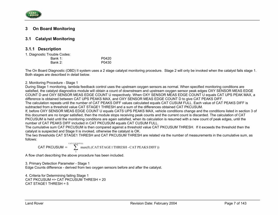
The On Board Diagnostic (OBD) II system uses a 2 stage catalyst monitoring procedure. Stage 2 will only be invoked when the catalyst fails stage 1. Both stages are described in detail below. 2. Monitoring Procedure - Stage 1 During Stage 1 monitoring, lambda feedback control uses the upstream oxygen sensors as normal. When specified monitoring conditions are satisfied, the catalyst diagnostics module will obtain a count of downstream and upstream oxygen sensor peak edges OXY SENSOR MEAS EDGE COUNT D and OXY SENSOR MEAS EDGE COUNT U respectively. When OXY SENSOR MEAS EDGE COUNT U equals CAT UPS PEAK MAX, a difference is obtained between CAT UPS PEAKS MAX, and OXY SENSOR MEAS EDGE COUNT D to give CAT PEAKS DIFF. The calculation repeats until the number of CAT PEAKS DIFF values calculated equals CAT CUSUM FULL. Each value of CAT PEAKS DIFF is subtracted from a threshold value CAT STAGE1 THRESH and a sum of the differences obtained CAT PKCUSUM. If, before OXY SENSOR MEAS EDGE COUNT U equals CATS UPS PEAKS MAX, vehicle conditions change and the conditions listed in section 3 of this document are no longer satisfied, then the module stops receiving peak counts and the current count is discarded. The calculation of CAT PKCUSUM is held until the monitoring conditions are again satisfied, when its calculation is resumed with a new count of peak edges, until the number of CAT PEAKS DIFF included in CAT PKCUSUM equals CAT CUSUM FULL. The cumulative sum CAT PKCUSUM is then compared against a threshold value CAT PKCUSUM THRESH. If it exceeds the threshold then the catalyst is suspected and Stage II is invoked, otherwise the catalyst is OK. The two thresholds CAT STAGE1 THRESH and CAT PKCUSUM THRESH are related via the number of measurements in the cumulative sum, as follows:
CAT PKCUSUM ∑=FULL CUSUM CAT
1)) DIFF PEAKS CAT - THRESH 1 STAGE (CATmax(0,
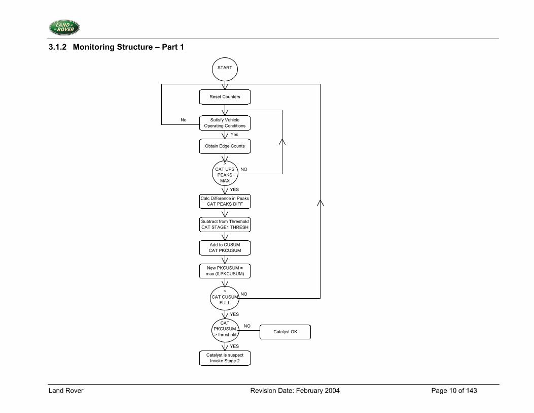
A flow chart describing the above procedure has been included. 3. Primary Detection Parameter - Stage 1 Edge Counts difference - derived from two oxygen sensors before and after the catalyst. 4. Criteria for Determining failing Stage 1 CAT PKCUSUM => CAT PKCUSUM THRESH = 20 CAT STAGE1 THRESH = 5
Land Rover Revision Date: February 2004 Page 8 of 143
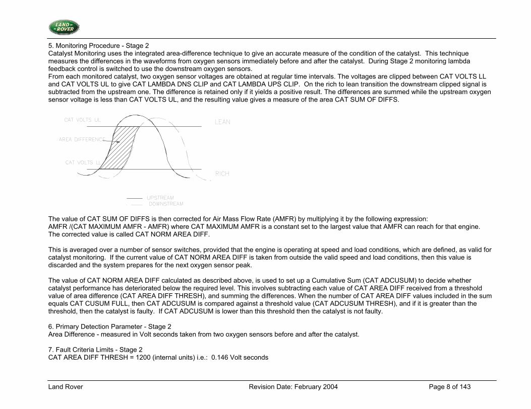
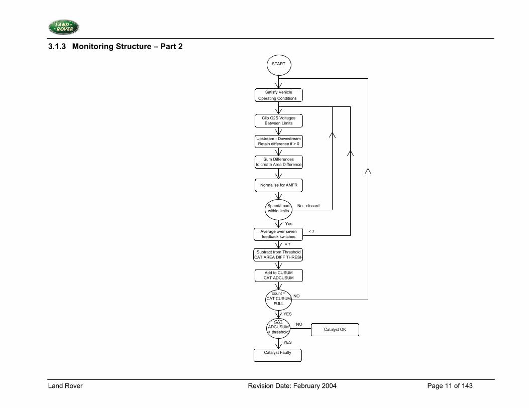
5. Monitoring Procedure - Stage 2 Catalyst Monitoring uses the integrated area-difference technique to give an accurate measure of the condition of the catalyst. This technique measures the differences in the waveforms from oxygen sensors immediately before and after the catalyst. During Stage 2 monitoring lambda feedback control is switched to use the downstream oxygen sensors. From each monitored catalyst, two oxygen sensor voltages are obtained at regular time intervals. The voltages are clipped between CAT VOLTS LL and CAT VOLTS UL to give CAT LAMBDA DNS CLIP and CAT LAMBDA UPS CLIP. On the rich to lean transition the downstream clipped signal is subtracted from the upstream one. The difference is retained only if it yields a positive result. The differences are summed while the upstream oxygen sensor voltage is less than CAT VOLTS UL, and the resulting value gives a measure of the area CAT SUM OF DIFFS.
The value of CAT SUM OF DIFFS is then corrected for Air Mass Flow Rate (AMFR) by multiplying it by the following expression: AMFR /(CAT MAXIMUM AMFR - AMFR) where CAT MAXIMUM AMFR is a constant set to the largest value that AMFR can reach for that engine. The corrected value is called CAT NORM AREA DIFF. This is averaged over a number of sensor switches, provided that the engine is operating at speed and load conditions, which are defined, as valid for catalyst monitoring. If the current value of CAT NORM AREA DIFF is taken from outside the valid speed and load conditions, then this value is discarded and the system prepares for the next oxygen sensor peak. The value of CAT NORM AREA DIFF calculated as described above, is used to set up a Cumulative Sum (CAT ADCUSUM) to decide whether catalyst performance has deteriorated below the required level. This involves subtracting each value of CAT AREA DIFF received from a threshold value of area difference (CAT AREA DIFF THRESH), and summing the differences. When the number of CAT AREA DIFF values included in the sum equals CAT CUSUM FULL, then CAT ADCUSUM is compared against a threshold value (CAT ADCUSUM THRESH), and if it is greater than the threshold, then the catalyst is faulty. If CAT ADCUSUM is lower than this threshold then the catalyst is not faulty. 6. Primary Detection Parameter - Stage 2 Area Difference - measured in Volt seconds taken from two oxygen sensors before and after the catalyst. 7. Fault Criteria Limits - Stage 2 CAT AREA DIFF THRESH = 1200 (internal units) i.e.: 0.146 Volt seconds
Land Rover Revision Date: February 2004 Page 9 of 143
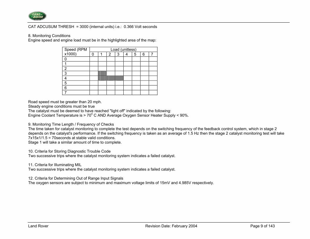
CAT ADCUSUM THRESH = 3000 (internal units) i.e.: 0.366 Volt seconds 8. Monitoring Conditions Engine speed and engine load must be in the highlighted area of the map:
Load (unitless) Speed (RPM x1000) 0 1 2 3 4 5 6 7 0 1 2 3 4 5 6 7
Road speed must be greater than 20 mph. Steady engine conditions must be true The catalyst must be deemed to have reached "light off" indicated by the following: Engine Coolant Temperature is > 700 C AND Average Oxygen Sensor Heater Supply < 90%. 9. Monitoring Time Length / Frequency of Checks The time taken for catalyst monitoring to complete the test depends on the switching frequency of the feedback control system, which in stage 2 depends on the catalyst's performance. If the switching frequency is taken as an average of 1.5 Hz then the stage 2 catalyst monitoring test will take 7x15x1/1.5 = 70seconds at stable valid conditions. Stage 1 will take a similar amount of time to complete. 10. Criteria for Storing Diagnostic Trouble Code Two successive trips where the catalyst monitoring system indicates a failed catalyst. 11. Criteria for Illuminating MIL Two successive trips where the catalyst monitoring system indicates a failed catalyst. 12. Criteria for Determining Out of Range Input Signals The oxygen sensors are subject to minimum and maximum voltage limits of 15mV and 4.985V respectively.
Land Rover Revision Date: February 2004 Page 10 of 143
3.1.2 Monitoring Structure – Part 1
START
Add to CUSUM
New PKCUSUM =
CAT PKCUSUM
max (0,PKCUSUM)
>CAT CUSUM
FULL
CATPKCUSUM> threshold
Satisfy VehicleOperating Conditions
Obtain Edge Counts
CAT UPSPEAKS
MAX
>
Calc Difference in PeaksCAT PEAKS DIFF
Subtract from ThresholdCAT STAGE1 THRESH
NO
YES
NO
YES
NO
YES
Catalyst OK
Catalyst is suspectInvoke Stage 2
Reset Counters
No
Yes
Land Rover Revision Date: February 2004 Page 11 of 143
3.1.3 Monitoring Structure – Part 2
Catalyst Faulty
START
Satisfy VehicleOperating Conditions
Clip O2S Voltages
Sum Differences
Between Limits
Upstream - DownstreamRetain difference if > 0
No - discard Speed/Loadwithin limits
Yes
Add to CUSUMCAT ADCUSUM
count =CAT CUSUM
FULL
Subtract from ThresholdCAT AREA DIFF THRESH
NO
YES
YES
CATADCUSUM> threshold
NOCatalyst OK
Normalise for AMFR
to create Area Difference
Average over sevenfeedback switches
< 7
= 7
Land Rover Revision Date: February 2004 Page 12 of 143
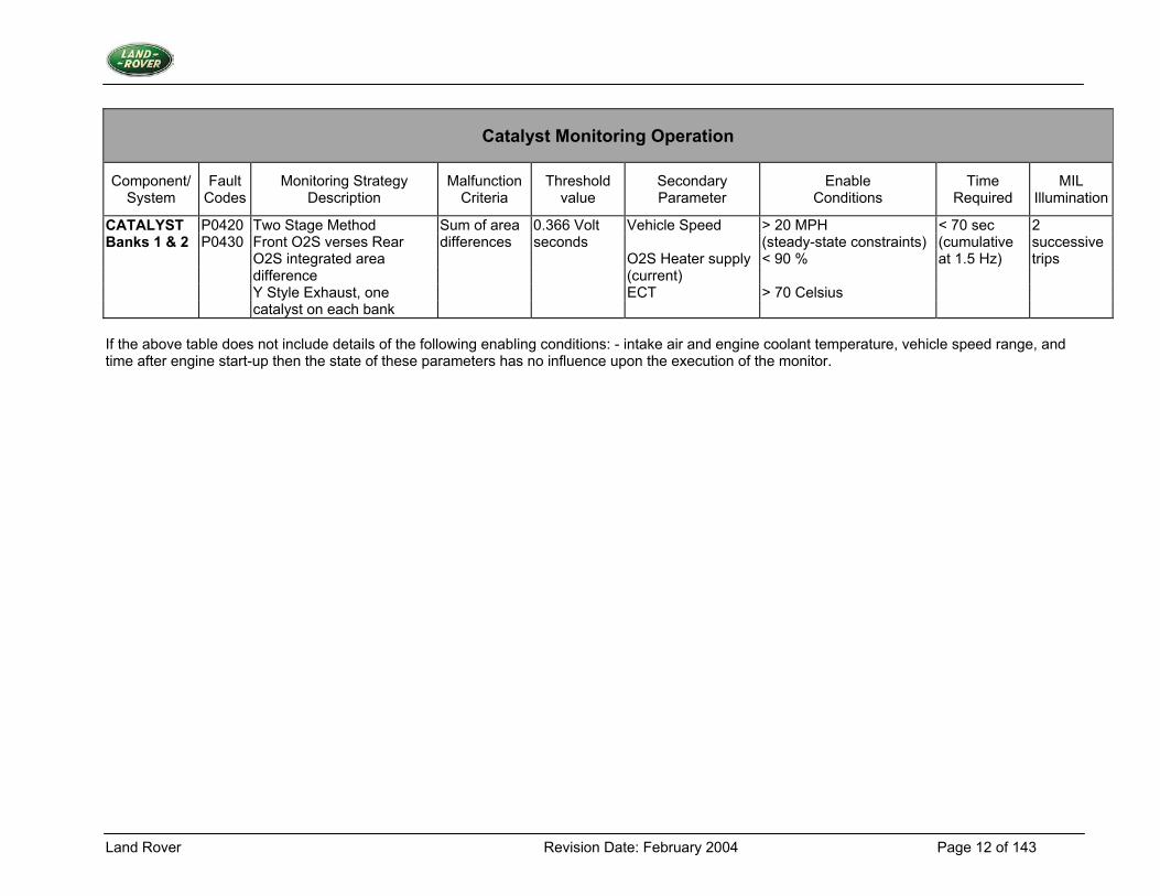
Catalyst Monitoring Operation
Component/ System
Fault Codes
Monitoring Strategy Description
Malfunction Criteria
Threshold value
Secondary Parameter
Enable Conditions
Time Required
MIL Illumination
CATALYST P0420 Two Stage Method Sum of area 0.366 Volt Vehicle Speed > 20 MPH < 70 sec 2 Banks 1 & 2 P0430 Front O2S verses Rear differences seconds (steady-state constraints) (cumulative successive O2S integrated area O2S Heater supply < 90 % at 1.5 Hz) trips difference (current) Y Style Exhaust, one ECT > 70 Celsius catalyst on each bank If the above table does not include details of the following enabling conditions: - intake air and engine coolant temperature, vehicle speed range, and time after engine start-up then the state of these parameters has no influence upon the execution of the monitor.
Land Rover Revision Date: February 2004 Page 13 of 143
3.2 Misfire Monitoring
3.2.1 Description 1. Diagnostic Trouble Codes: Individual DTCs for each cylinder, for either excess emissions or catalyst damage and corresponding multiple cylinder codes.
Catalyst Damage Bank A Misfire Fault P1313 Catalyst Damage Bank B Misfire Fault P1314 Excess Emissions Misfire Fault P1316 Random / Multiple Misfire P0300 Misfire Detected - Cylinder 1 P0301 Misfire Detected - Cylinder 2 P0302 Misfire Detected - Cylinder 3 P0303 Misfire Detected - Cylinder 4 P0304 Misfire Detected - Cylinder 5 P0305 Misfire Detected - Cylinder 6 P0306 Misfire Detected - Cylinder 7 P0307 Misfire Detected - Cylinder 8 P0308
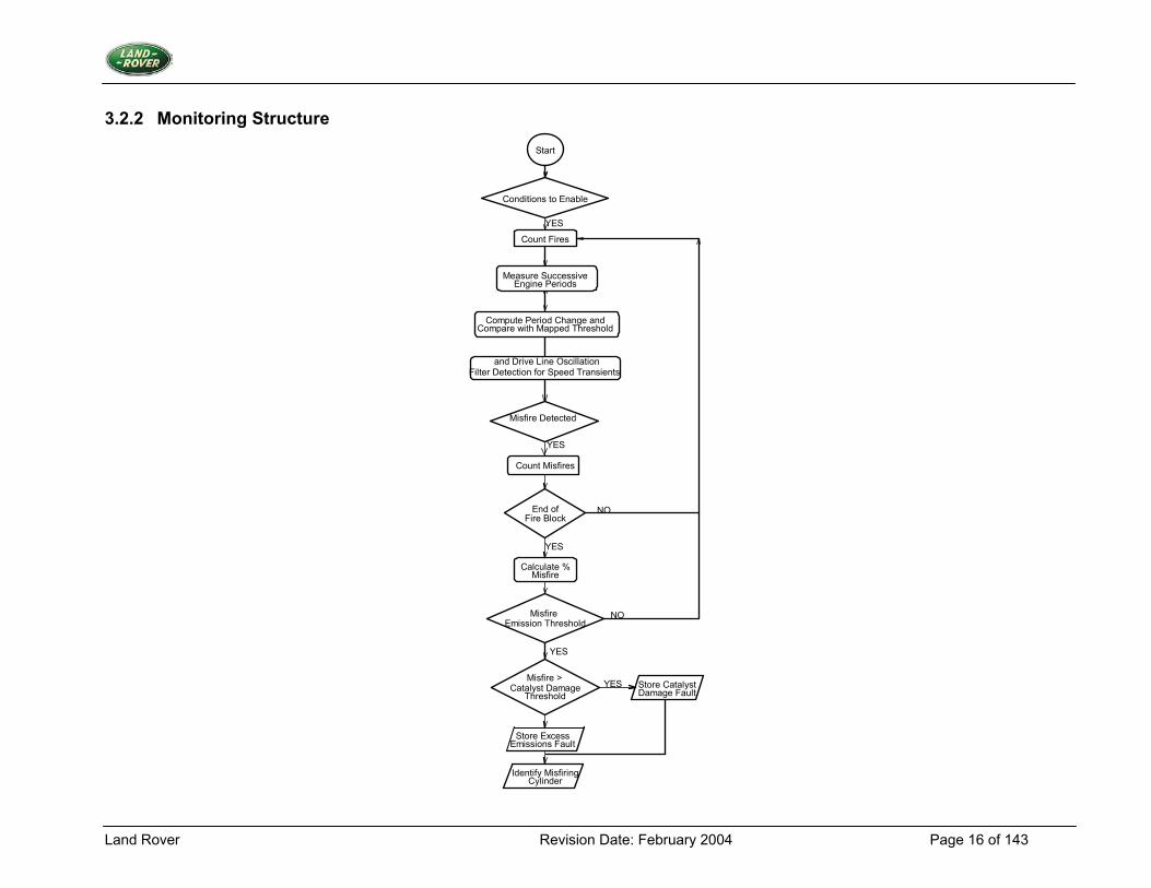
2. Monitoring Procedure Misfire detection using crankshaft period measurements has been implemented. Two algorithms compare changes in crankshaft period with respective threshold values that are speed and load dependant. If the change in crankshaft period exceeds the threshold value a misfire has occurred. Percentage misfire is calculated over 200 or 1000 engine revolution blocks for each bank of cylinders and compared to threshold levels for excess emissions or catalyst damage. Whenever conditions are not suitable for misfire detection, engine revolution counting and misfire counting is suspended. When conditions are suitable, counting continues from the last updated values. Catalyst Damage The total percentage misfire indicated by the algorithm is calculated in blocks of 200 revolutions of the crankshaft. If this value exceeds the misfire rate that indicates catalyst damage (MF DIAG THRESH PCENT MF CAT), cylinder identification takes place and a misfire catalyst damage fault is present for the appropriate bank. Excess Emissions The percentage misfire (MF DIAG PCENT MF EMISS) is calculated in blocks of 1000 revolutions of the crankshaft using MF DIAG FIRE COUNT EMISS I as the revolution count. If the misfire rate is high enough to exceed specified emission limits, cylinder identification takes place and a misfire emission fault is present.
Land Rover Revision Date: February 2004 Page 14 of 143
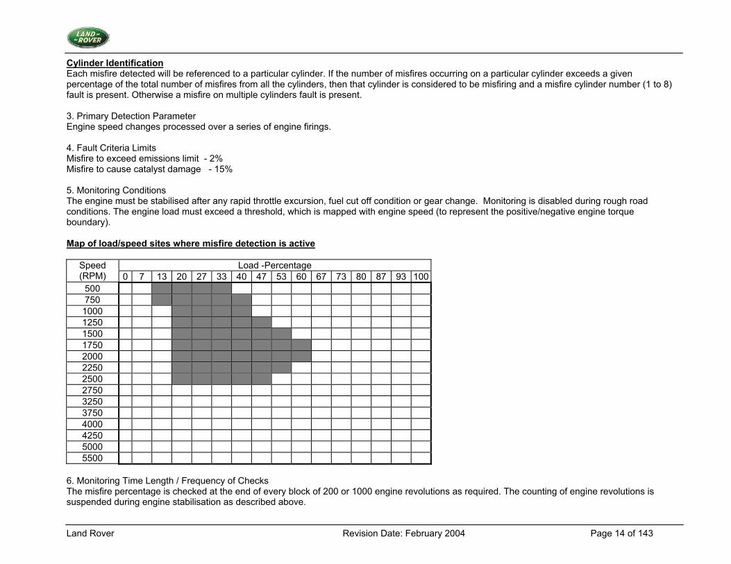
Cylinder Identification Each misfire detected will be referenced to a particular cylinder. If the number of misfires occurring on a particular cylinder exceeds a given percentage of the total number of misfires from all the cylinders, then that cylinder is considered to be misfiring and a misfire cylinder number (1 to 8) fault is present. Otherwise a misfire on multiple cylinders fault is present. 3. Primary Detection Parameter Engine speed changes processed over a series of engine firings. 4. Fault Criteria Limits Misfire to exceed emissions limit - 2% Misfire to cause catalyst damage - 15% 5. Monitoring Conditions The engine must be stabilised after any rapid throttle excursion, fuel cut off condition or gear change. Monitoring is disabled during rough road conditions. The engine load must exceed a threshold, which is mapped with engine speed (to represent the positive/negative engine torque boundary). Map of load/speed sites where misfire detection is active
Load -Percentage Speed (RPM) 0 7 13 20 27 33 40 47 53 60 67 73 80 87 93 100
500 750
1000 1250 1500 1750 2000 2250 2500 2750 3250 3750 4000 4250 5000 5500
6. Monitoring Time Length / Frequency of Checks The misfire percentage is checked at the end of every block of 200 or 1000 engine revolutions as required. The counting of engine revolutions is suspended during engine stabilisation as described above.
Land Rover Revision Date: February 2004 Page 15 of 143
7. Criteria for Storing Fault Code If catalyst damage levels of misfire are detected the fault code is stored immediately. If misfire above the emission threshold (only) is detected, then a set of conditions is stored. A DTC will be stored if misfire is detected on a subsequent driving cycle while the conditions are still stored. The conditions can be erased on intervening fault free driving cycles as allowed in OBD II regulations. 8. Criteria for Illuminating MIL If catalyst damage levels of misfire are detected the MIL will be flashed for as long as the catalyst damage misfire level is present. If misfire above the emission threshold (only) is detected, then a set of conditions is stored. The MIL will be illuminated if misfire is detected on a subsequent driving cycle while the conditions are still stored. The conditions can be erased on intervening fault free driving cycles as allowed in OBD II regulations. 9. Criteria for Determining Out of Range Input Signals The crankshaft position sensing system is subject to diagnostics, which detect more or less than the correct number of sensor transitions per engine revolution.
Land Rover Revision Date: February 2004 Page 16 of 143
3.2.2 Monitoring Structure
Conditions to Enable
Count Fires
Start
Misfire Detected
End ofFire Block
Calculate %Misfire
Misfire Emission Threshold
Misfire >Catalyst Damage
Threshold
Identify MisfiringCylinder
YES
YES
NO
YES
NO
YES
YES
Engine PeriodsMeasure Successive
Compute Period Change andCompare with Mapped Threshold
and Drive Line OscillationFilter Detection for Speed Transients
Count Misfires
Store Catalyst Damage Fault
Store ExcessEmissions Fault
Land Rover Revision Date: February 2004 Page 17 of 143
Misfire Monitoring Operation
Component/ System
Fault Codes
Monitoring StrategyDescription
Malfunction Criteria
Thresholdvalue
Secondary Parameter
Enable Conditions
Time Required
MIL Illumination
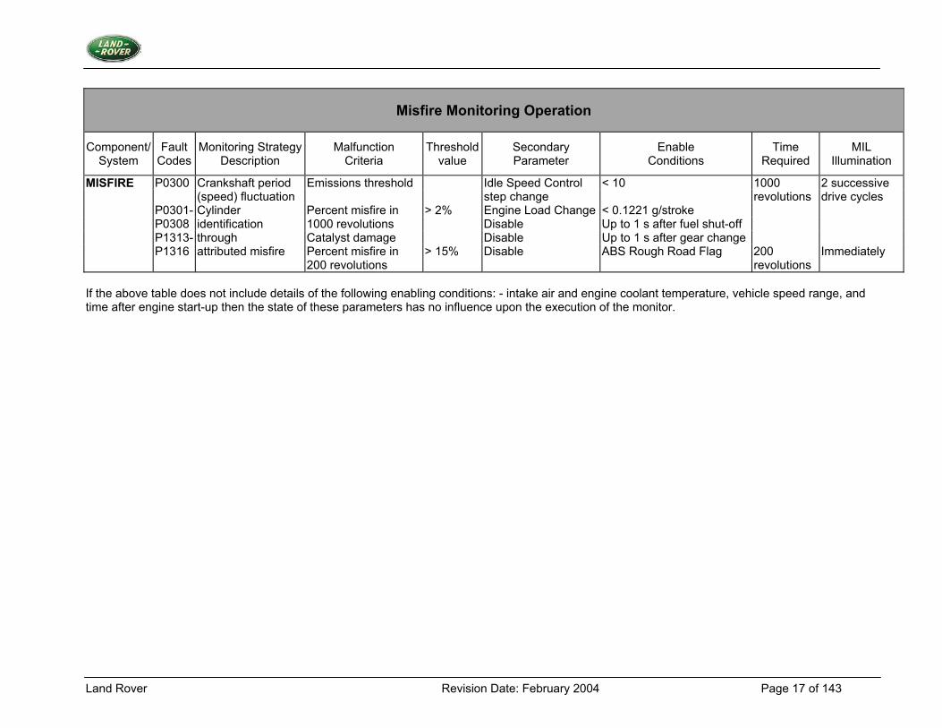
MISFIRE P0300 Crankshaft period Emissions threshold Idle Speed Control < 10 1000 2 successive (speed) fluctuation step change revolutions drive cycles P0301- Cylinder Percent misfire in > 2% Engine Load Change < 0.1221 g/stroke P0308 identification 1000 revolutions Disable Up to 1 s after fuel shut-off P1313- through Catalyst damage Disable Up to 1 s after gear change P1316 attributed misfire Percent misfire in > 15% Disable ABS Rough Road Flag 200 Immediately 200 revolutions revolutions If the above table does not include details of the following enabling conditions: - intake air and engine coolant temperature, vehicle speed range, and time after engine start-up then the state of these parameters has no influence upon the execution of the monitor.
Land Rover Revision Date: February 2004 Page 18 of 143
3.3 Evaporative Emission System Monitoring
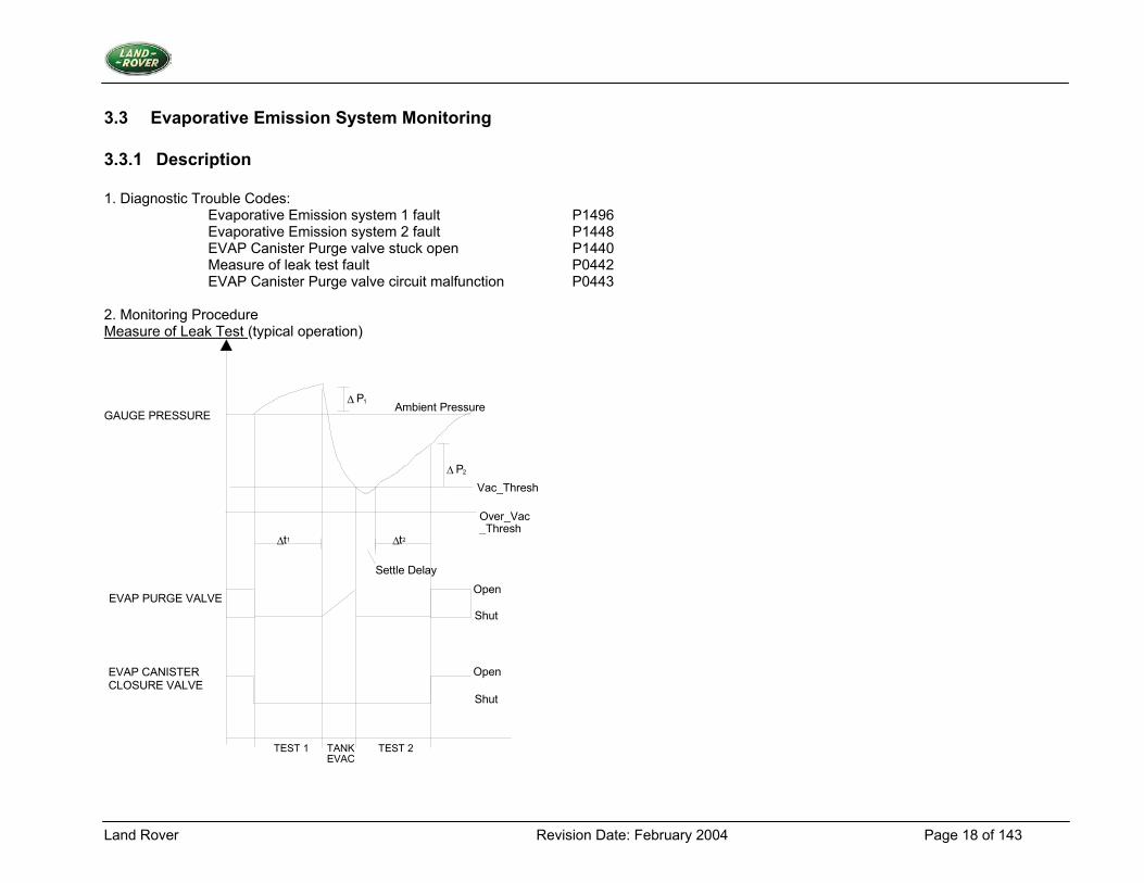
3.3.1 Description 1. Diagnostic Trouble Codes: Evaporative Emission system 1 fault P1496 Evaporative Emission system 2 fault P1448 EVAP Canister Purge valve stuck open P1440 Measure of leak test fault P0442 EVAP Canister Purge valve circuit malfunction P0443 2. Monitoring Procedure Measure of Leak Test (typical operation)
Ambient Pressure
Open
Shut
Shut
EVAP CANISTER CLOSURE VALVE
EVAP PURGE VALVE
GAUGE PRESSURE
Vac_Thresh
Settle Delay
∆ t 2∆ t 1
Over_Vac _Thresh
∆ P 1
∆ P 2
TEST 1 TEST 2 TANK EVAC
Open
Land Rover Revision Date: February 2004 Page 19 of 143
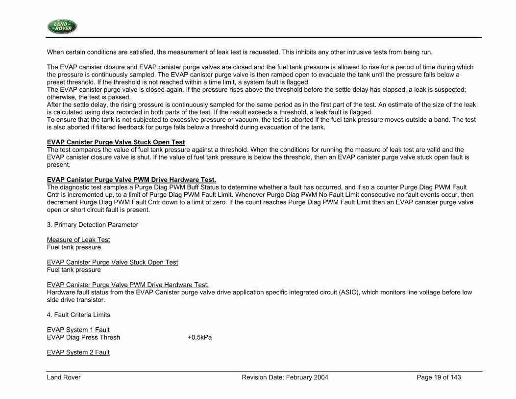
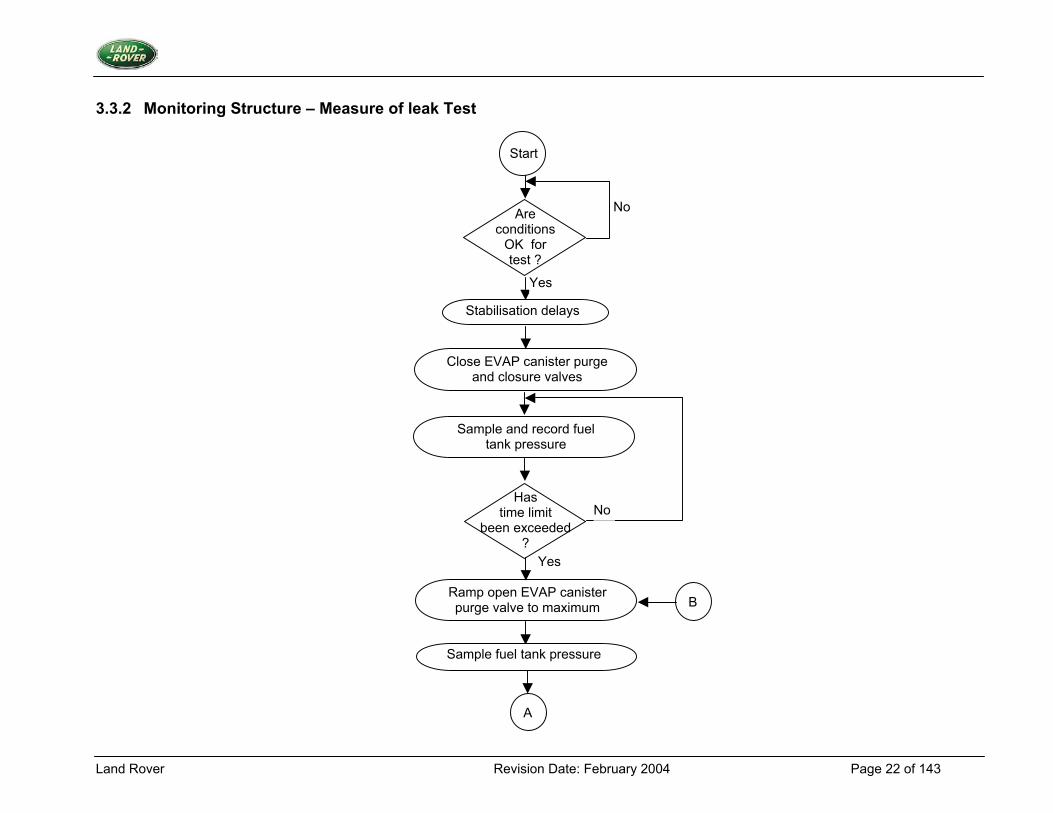
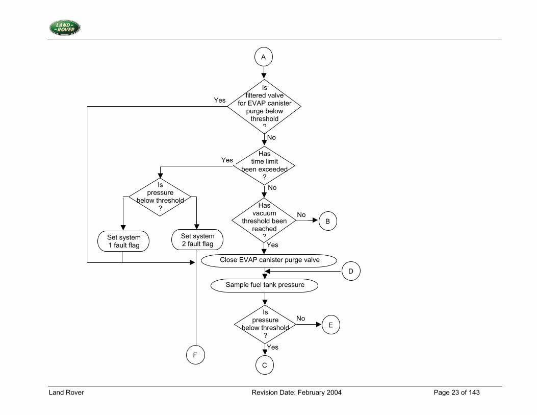
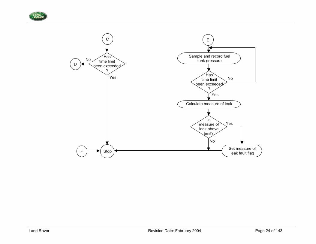
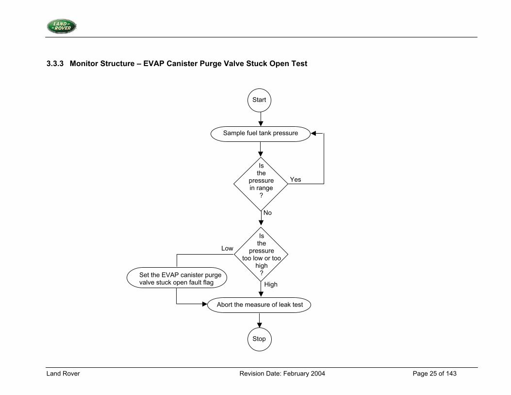
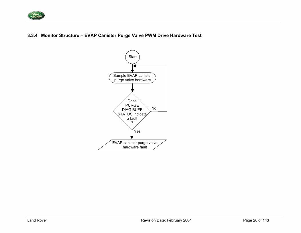
When certain conditions are satisfied, the measurement of leak test is requested. This inhibits any other intrusive tests from being run. The EVAP canister closure and EVAP canister purge valves are closed and the fuel tank pressure is allowed to rise for a period of time during which the pressure is continuously sampled. The EVAP canister purge valve is then ramped open to evacuate the tank until the pressure falls below a preset threshold. If the threshold is not reached within a time limit, a system fault is flagged. The EVAP canister purge valve is closed again. If the pressure rises above the threshold before the settle delay has elapsed, a leak is suspected; otherwise, the test is passed. After the settle delay, the rising pressure is continuously sampled for the same period as in the first part of the test. An estimate of the size of the leak is calculated using data recorded in both parts of the test. If the result exceeds a threshold, a leak fault is flagged. To ensure that the tank is not subjected to excessive pressure or vacuum, the test is aborted if the fuel tank pressure moves outside a band. The test is also aborted if filtered feedback for purge falls below a threshold during evacuation of the tank. EVAP Canister Purge Valve Stuck Open Test The test compares the value of fuel tank pressure against a threshold. When the conditions for running the measure of leak test are valid and the EVAP canister closure valve is shut. If the value of fuel tank pressure is below the threshold, then an EVAP canister purge valve stuck open fault is present. EVAP Canister Purge Valve PWM Drive Hardware Test. The diagnostic test samples a Purge Diag PWM Buff Status to determine whether a fault has occurred, and if so a counter Purge Diag PWM Fault Cntr is incremented up, to a limit of Purge Diag PWM Fault Limit. Whenever Purge Diag PWM No Fault Limit consecutive no fault events occur, then decrement Purge Diag PWM Fault Cntr down to a limit of zero. If the count reaches Purge Diag PWM Fault Limit then an EVAP canister purge valve open or short circuit fault is present. 3. Primary Detection Parameter Measure of Leak Test Fuel tank pressure EVAP Canister Purge Valve Stuck Open Test Fuel tank pressure EVAP Canister Purge Valve PWM Drive Hardware Test. Hardware fault status from the EVAP Canister purge valve drive application specific integrated circuit (ASIC), which monitors line voltage before low side drive transistor. 4. Fault Criteria Limits EVAP System 1 Fault EVAP Diag Press Thresh +0.5kPa EVAP System 2 Fault
Land Rover Revision Date: February 2004 Page 20 of 143
EVAP Diag Press Thresh +0.5kPa Measure of Leak Test Fault EVAP Diag Measure of Leak Thresh 50 (decimal) EVAP Canister Purge Valve PWM Drive Hardware Test. EVAP Canister Purge Diag PWM Fault Limit 255 samples EVAP Canister Purge Valve Stuck Open EVAP Diag Over Vac Thresh -3.5kPa 5. Monitoring Conditions The measure of leak test will not run (or shall abort) when the following faults or defaults are present: Multiple cylinder misfire fault Fuel tank pressure out of range EVAP Canister Purge valve open or short circuit fault Any fuel level sensor fault Any oxygen sensor fault Any oxygen sensor heater fault Any intake air temperature fault After a delay following the exit of the cranking condition, the EVAP diagnostic monitors for the following conditions to be true before the test is started: Manifold depression exceeds the EVAP threshold Road speed within range EVAP Canister Purge feedback adaptation above the EVAP Canister purge adaptation limit Closed loop fuelling is active on both banks Steady state conditions are present Fuel level within the EVAP range OBD-II warm up conditions are satisfied Fuelling feed back is off clamp on both banks Fuelling feed back is not in default Intake air temperature is above the EVAP limit The EVAP Canister Purge Valve PWM hardware test occurs continuously 6. Monitoring Time Length / Frequency of Checks The Measure of Leak Test diagnostic runs at a frequency of once per trip. The hardware test runs at 10Hz. 7. Criteria for Storing a Diagnostic Trouble Code Two successive trips where the diagnostic routines indicate a fuel system leak or a failed EVAP canister purge valve or EVAP canister purge valve circuit.
Land Rover Revision Date: February 2004 Page 21 of 143
8. Criteria for Illuminating MIL Two successive trips where the diagnostic routines indicate a fuel system leak or a failed EVAP canister purge valve or EVAP canister purge valve circuit. 9. Criteria for Determining Out of Range Input Signals The hardware sampling technique monitors non-linear signals; the criteria will be signal/no signal.
Land Rover Revision Date: February 2004 Page 22 of 143
3.3.2 Monitoring Structure – Measure of leak Test
Start
Are conditions
OK for test ?
Stabilisation delays
Close EVAP canister purge and closure valves
Sample and record fuel tank pressure
Has time limit
been exceeded ?
Ramp open EVAP canister purge valve to maximum
Sample fuel tank pressure
A
B
No
Yes
No
Yes
Land Rover Revision Date: February 2004 Page 23 of 143
Is filtered valve
for EVAP canister purge below
threshold ?
A
Has time limit
been exceeded ?
Has vacuum
threshold been reached
?
B
Is pressure
below threshold ?
Set system 1 fault flag
Set system 2 fault flag
Close EVAP canister purge valve
Sample fuel tank pressure
Is pressure
below threshold ?
C
D
E
F
No
No
Yes
Yes
No
Yes
No
Yes
Land Rover Revision Date: February 2004 Page 24 of 143
EC
Has time limit
been exceeded ?
D
StopF
Sample and record fuel tank pressure
Has time limit
been exceeded ?
Calculate measure of leak
Is measure of leak above
limit?
Set measure of leak fault flag
No
Yes No
Yes
No
Yes
Land Rover Revision Date: February 2004 Page 25 of 143
3.3.3 Monitor Structure – EVAP Canister Purge Valve Stuck Open Test
Start
Sample fuel tank pressure
Is the
pressure in range
?
No
Yes
Is the
pressure too low or too
high ? Set the EVAP canister purge
valve stuck open fault flag
Abort the measure of leak test
High
Low
Stop
Land Rover Revision Date: February 2004 Page 26 of 143
3.3.4 Monitor Structure – EVAP Canister Purge Valve PWM Drive Hardware Test
Start
Sample EVAP canister purge valve hardware
Does PURGE
DIAG BUFF STATUS indicate
a fault ?
No
EVAP canister purge valve hardware fault
Yes
Land Rover Revision Date: February 2004 Page 27 of 143
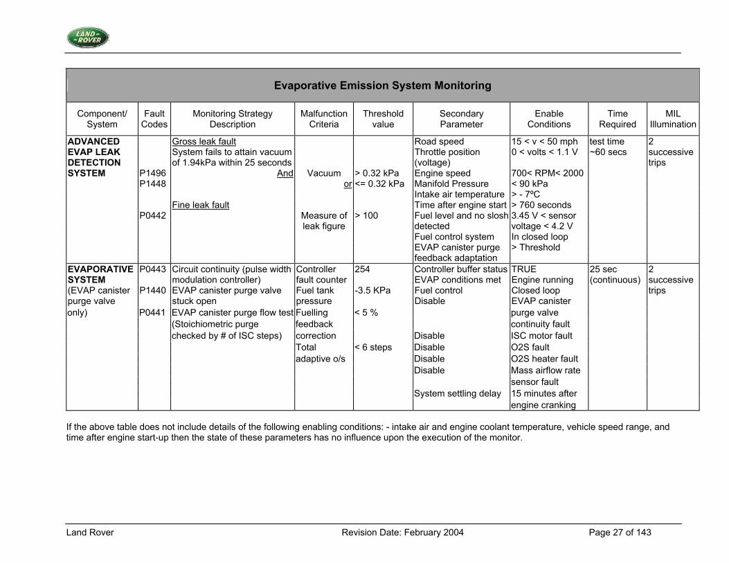
Evaporative Emission System Monitoring
Component/ System
Fault Codes
Monitoring Strategy Description
Malfunction Criteria
Threshold value
Secondary Parameter
Enable Conditions
Time Required
MIL Illumination
ADVANCED Gross leak fault Road speed 15 < v < 50 mph test time 2 EVAP LEAK System fails to attain vacuum Throttle position 0 < volts < 1.1 V ~60 secs successive DETECTION of 1.94kPa within 25 seconds (voltage) trips SYSTEM P1496 And Vacuum > 0.32 kPa Engine speed 700< RPM< 2000 P1448 or <= 0.32 kPa Manifold Pressure < 90 kPa Intake air temperature > - 7ºC Fine leak fault Time after engine start > 760 seconds P0442 Measure of > 100 Fuel level and no slosh 3.45 V < sensor leak figure detected voltage < 4.2 V Fuel control system In closed loop EVAP canister purge > Threshold feedback adaptation EVAPORATIVE P0443 Circuit continuity (pulse width Controller 254 Controller buffer status TRUE 25 sec 2 SYSTEM modulation controller) fault counter EVAP conditions met Engine running (continuous) successive (EVAP canister P1440 EVAP canister purge valve Fuel tank -3.5 KPa Fuel control Closed loop trips purge valve stuck open pressure Disable EVAP canister only) P0441 EVAP canister purge flow test Fuelling < 5 % purge valve (Stoichiometric purge feedback continuity fault checked by # of ISC steps) correction Disable ISC motor fault Total < 6 steps Disable O2S fault adaptive o/s Disable O2S heater fault Disable Mass airflow rate sensor fault System settling delay 15 minutes after engine cranking If the above table does not include details of the following enabling conditions: - intake air and engine coolant temperature, vehicle speed range, and time after engine start-up then the state of these parameters has no influence upon the execution of the monitor.
Land Rover Revision Date: February 2004 Page 28 of 143
3.4 EVAP Canister Closure Valve
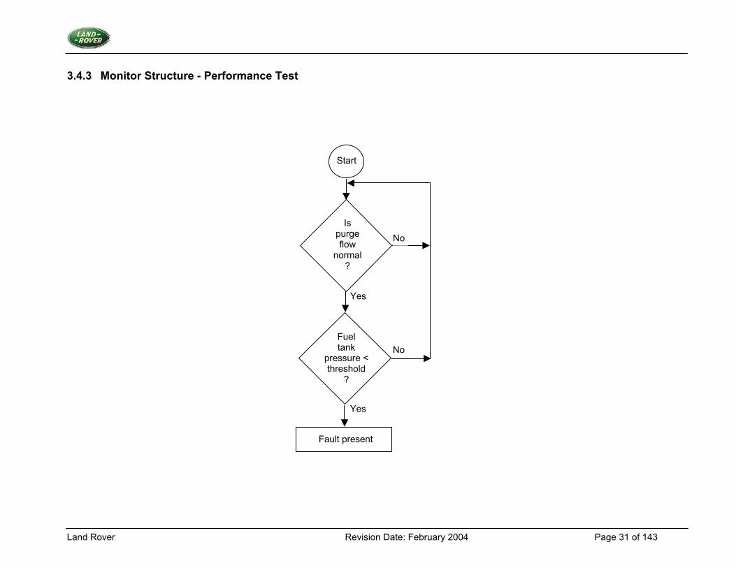
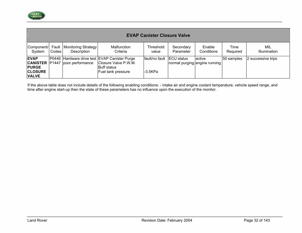
3.4.1 Description 1. Diagnostic Trouble Codes: EVAP canister closure valve malfunction: P0446 EVAP canister closure valve performance: P1447 2. Monitoring Procedure EVAP Canister Closure Valve PWM Drive Hardware Test The diagnostic test samples Close Valve Diag PWM Buff Status to determine whether a fault has occurred, and if so a counter Close Valve Diag PWM Fault Cntr is incremented up, to a limit of Close Valve Diag PWM Fault Limit. If no fault event occurs, then decrement Close Valve Diag PWM Fault Cntr down to a limit of zero. If the count reaches the limit Close Valve Diag PWM Fault Limit then an EVAP canister closure valve open or short circuit fault is present. EVAP Canister Closure Valve Performance Test The test compares the value of fuel tank pressure against a threshold, during normal purge operation. If the value of FUEL TANK PRESS VOLTS is less than CLOSE VALVE BLOCKED PRESS, then an appropriate fault counter is incremented up to a limit of close valve blocked diagnostic fault limit. Otherwise the fault counter is decremented down to a limit of zero. If the fault counter reaches the limit then an EVAP canister closure valve flow fault is present. 3. Primary Detection Parameter EVAP Canister Closure Valve PWM Drive Hardware Test Hardware fault status from EVAP canister closure valve drive ASIC which monitors line voltage before low side drive transistor. EVAP Canister Closure Valve Performance Test Fuel tank pressure - Measured in volts, the outcome of a potential divider calculation. 4. Fault Criteria Limits EVAP Canister Closure Valve Diag PWM Fault Limit 50 samples EVAP Canister Closure Valve Blocked Pressure -3.5 kPa 5. Monitoring Conditions The EVAP canister closure valve PWM drive hardware test occurs continuously. The performance test will take place during normal purge operation. 6. Monitoring Time Length / Frequency of Checks The frequency of the EVAP canister closure valve diagnostic is 10Hz. 7. Criteria for Storing a Diagnostic Trouble Code Two successive trips where the diagnostic routines indicate a failed valve or valve circuit.
Land Rover Revision Date: February 2004 Page 29 of 143
8. Criteria for Illuminating MIL Two successive trips where the diagnostic routines indicate a failed valve or valve circuit. 9. Criteria for Determining Out of Range Input Signals The hardware sampling technique monitors non-linear signals; the criteria will be signal/no signal.
Land Rover Revision Date: February 2004 Page 30 of 143
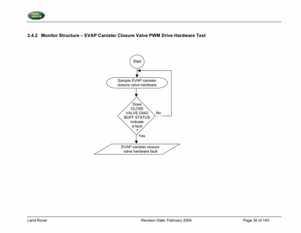
3.4.2 Monitor Structure – EVAP Canister Closure Valve PWM Drive Hardware Test
Start
Sample EVAP canister closure valve hardware
Does CLOSE
VALVE DIAG BUFF STATUS
indicate a fault
?
No
EVAP canister closure valve hardware fault
Yes
Land Rover Revision Date: February 2004 Page 31 of 143
3.4.3 Monitor Structure - Performance Test
Start
Fuel tank
pressure < threshold
?
No
Yes
Is purge flow
normal ?
No
Yes
Fault present
Land Rover Revision Date: February 2004 Page 32 of 143
EVAP Canister Closure Valve
Component/ System
Fault Codes
Monitoring StrategyDescription
Malfunction Criteria
Threshold value
Secondary Parameter
Enable Conditions
Time Required
MIL Illumination
EVAP P0446 Hardware drive test EVAP Canister Purge fault/no fault ECU status active 50 samples 2 successive trips CANISTER P1447 poor performance Closure Valve P.W.M. normal purging engine running PURGE Buff status CLOSURE Fuel tank pressure -3.5KPa VALVE If the above table does not include details of the following enabling conditions: - intake air and engine coolant temperature, vehicle speed range, and time after engine start-up then the state of these parameters has no influence upon the execution of the monitor.
Land Rover Revision Date: February 2004 Page 33 of 143
3.5 Oxygen Sensor and Fuel System Monitoring
3.5.1 Description 1. Diagnostic Trouble Codes:
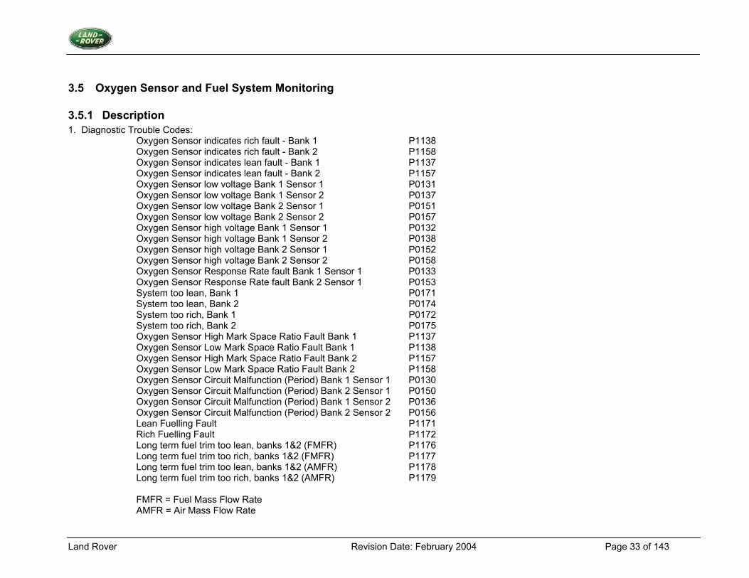
Oxygen Sensor indicates rich fault - Bank 1 P1138 Oxygen Sensor indicates rich fault - Bank 2 P1158 Oxygen Sensor indicates lean fault - Bank 1 P1137 Oxygen Sensor indicates lean fault - Bank 2 P1157 Oxygen Sensor low voltage Bank 1 Sensor 1 P0131 Oxygen Sensor low voltage Bank 1 Sensor 2 P0137 Oxygen Sensor low voltage Bank 2 Sensor 1 P0151 Oxygen Sensor low voltage Bank 2 Sensor 2 P0157 Oxygen Sensor high voltage Bank 1 Sensor 1 P0132 Oxygen Sensor high voltage Bank 1 Sensor 2 P0138 Oxygen Sensor high voltage Bank 2 Sensor 1 P0152 Oxygen Sensor high voltage Bank 2 Sensor 2 P0158 Oxygen Sensor Response Rate fault Bank 1 Sensor 1 P0133 Oxygen Sensor Response Rate fault Bank 2 Sensor 1 P0153 System too lean, Bank 1 P0171 System too lean, Bank 2 P0174 System too rich, Bank 1 P0172 System too rich, Bank 2 P0175 Oxygen Sensor High Mark Space Ratio Fault Bank 1 P1137 Oxygen Sensor Low Mark Space Ratio Fault Bank 1 P1138 Oxygen Sensor High Mark Space Ratio Fault Bank 2 P1157 Oxygen Sensor Low Mark Space Ratio Fault Bank 2 P1158 Oxygen Sensor Circuit Malfunction (Period) Bank 1 Sensor 1 P0130 Oxygen Sensor Circuit Malfunction (Period) Bank 2 Sensor 1 P0150 Oxygen Sensor Circuit Malfunction (Period) Bank 1 Sensor 2 P0136 Oxygen Sensor Circuit Malfunction (Period) Bank 2 Sensor 2 P0156 Lean Fuelling Fault P1171 Rich Fuelling Fault P1172 Long term fuel trim too lean, banks 1&2 (FMFR) P1176 Long term fuel trim too rich, banks 1&2 (FMFR) P1177 Long term fuel trim too lean, banks 1&2 (AMFR) P1178 Long term fuel trim too rich, banks 1&2 (AMFR) P1179 FMFR = Fuel Mass Flow Rate AMFR = Air Mass Flow Rate
Land Rover Revision Date: February 2004 Page 34 of 143
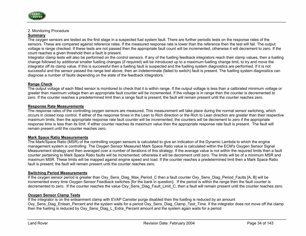
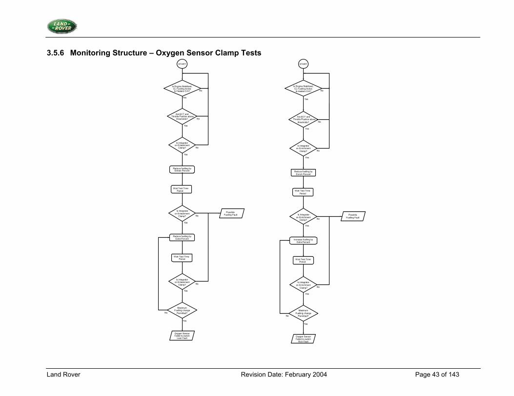
2. Monitoring Procedure Summary The oxygen sensors are tested as the first stage in a suspected fuel system fault. There are further periodic tests on the response rates of the sensors. These are compared against reference rates. If the measured response rate is lower than the reference then the test will fail. The output voltage is range checked. If these tests are not passed then the appropriate fault count will be incremented; otherwise it will decrement to zero. If the count reaches a given threshold then a fault is present. Integrator clamp tests will also be performed on the control sensors. If any of the fuelling feedback integrators reach their clamp values, then a fuelling change followed by additional smaller fuelling changes (if required) will be introduced up to a maximum fuelling change limit, to try and move the integrator off its clamp value. If this is successful then a fuelling fault is suspected and the fuelling system diagnostics are performed. If it is not successful and the sensor passed the range test above, then an indeterminate (failed to switch) fault is present. The fuelling system diagnostics can diagnose a number of faults depending on the state of the feedback integrators. Range Check The output voltage of each fitted sensor is monitored to check that it is within range. If the output voltage is less than a calibrated minimum voltage or greater than maximum voltage then an appropriate fault counter will be incremented. If the voltage is in range then the counter is decremented to zero. If the counter reaches a predetermined limit then a range fault is present; the fault will remain present until the counter reaches zero. Response Rate Measurements The response rates of the controlling oxygen sensors are measured. This measurement will take place during the normal sensor switching, which occurs in closed loop control. If either of the response times in the Lean to Rich direction or the Rich to Lean direction are greater than their respective maximum limits, then the appropriate response rate fault counter will be incremented; the counters will be decrement to zero if the appropriate response time is less than its limit. If either counter reaches its maximum value then the appropriate response rate fault is present. The fault will remain present until the counter reaches zero. Mark Space Ratio Measurements The Mark/Space Ratio (MSR) of the controlling oxygen sensors is calculated to give an indication of the Dynamic Lambda to which the engine management system is controlling. The Oxygen Sensor Measured Mark Space Ratio value is calculated within the ECM's Oxygen Sensor Signal Measurement strategy and then averaged over a number of iterations of this strategy. If the average value is not within the required limits then a fault counter pertaining to Mark Space Ratio faults will be incremented; otherwise it will be decrement until zero. The limits will be of a minimum MSR and maximum MSR. These limits will be mapped against engine speed and load. If the counter reaches a predetermined limit then a Mark Space Ratio fault is present; the fault will remain present until the counter reaches zero. Switching Period Measurements If the oxygen sensor period is greater than Oxy_Sens_Diag_Max_Period_C then a fault counter Oxy_Sens_Diag_Period_Faults [A, B] will be incremented every time Oxygen Sensor Feedback switches {for the bank in question}. If the period is within the range then the fault counter is decremented to zero. If the counter reaches the value Oxy_Sens_Diag_Fault_Limit_C, then a fault will remain present until the counter reaches zero. Oxygen Sensor Clamp Tests If the integrator is on the enleanment clamp with EVAP Canister purge disabled then the fuelling is reduced by an amount Oxy_Sens_Diag_Enlean_Percent and the system waits for a period Oxy_Sens_Diag_Clamp_Test_Time. If the integrator does not move off the clamp then the fuelling is reduced by Oxy_Sens_Diag_L_Extra_Percent amount and the system again waits for a period
Land Rover Revision Date: February 2004 Page 35 of 143
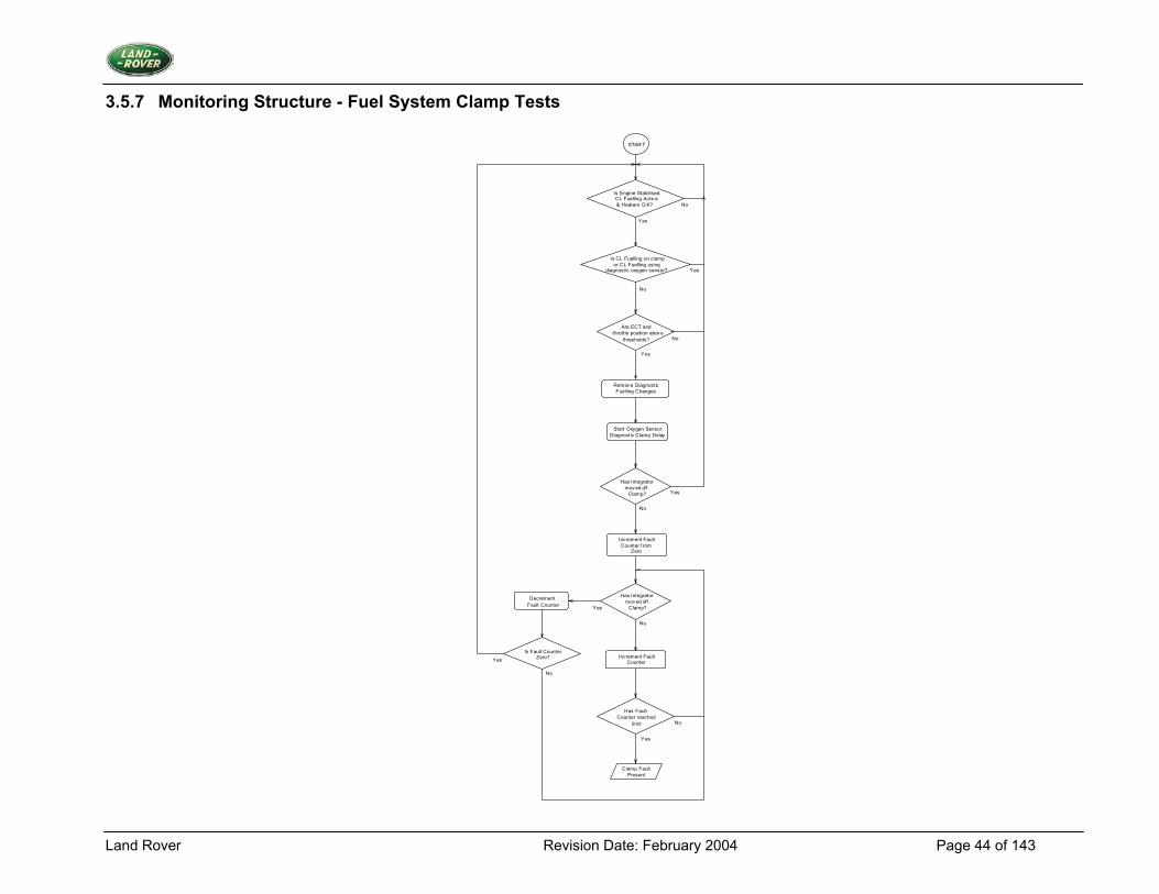
Oxy_Sens_Diag_Clamp_Test_Time. This will be repeated until the integrator moves off clamp or the fuelling has reached a maximum permitted fuelling change. If the fuelling change(s) caused the integrator to move off clamp then a fuelling fault is suspected and further fuel system diagnostics will be performed; if not then an Oxygen Sensor Failed to Switch Lean fault is present. All fuelling changes will be removed at this time. If the integrator is on the enrichment clamp then the fuelling is increased by an amount Oxy_Sens_Diag_Enrich_Percent and the system waits for a period Oxy_Sens_Diag_Clamp_Test_Time. If the integrator does not move off the clamp then the fuelling is increased by Oxy_Sens_Diag_R_Extra_Percent amount and the system again waits for a period Oxy_Sens_Diag_Clamp_Test_Time. This will be repeated until the integrator moves off clamp or the fuelling has reached a maximum permitted fuelling change. If the fuelling change(s) caused the integrator to move off clamp then a fuelling fault is suspected and further system diagnostics will be performed; if not then an Oxygen Sensor Failed to Switch Rich fault is present. All fuelling changes will be removed at this time. Note: Each bank's clamp test is considered to be a single intrusive test, only one test can be active at a time, with initial priority given to bank 1. Fuelling System Clamp Tests All diagnostic fuelling changes will be removed before performing the tests below. If an integrator returns to its clamp within a time designated by Oxy_Sens_Diag_Clamp_Delay then the conditions below will be applied. If this is not the case then this test is abandoned until again triggered by the oxygen sensor diagnostics. While a bank is on clamp, an appropriate fault counter for each bank will be incremented. If the bank moves off clamp then the counter will decrement until zero. An integrator clamp test for bank A or B is considered to be complete if the fault counter reaches zero or the fault limit. If the value of the fault counter reaches its limit value a clamp fault is present; the fault will remain present until the counter reaches zero. All clamp faults for that bank will be cleared when the counter reaches zero. When a clamp fault is present the conditions below will be applied to determine which fault is present. (1). One integrator is at the maximum enrichment clamp and the other not at the maximum enrichment clamp; a Reduced Fuel Flow Fault is present for the appropriate bank. (2). Both integrators are on the maximum enrichment clamp; a Lean Fuelling Fault is present. This diagnostic will be disabled if the fuel level is less than the permissible fuel level for the diagnostic. (3). One integrator is at the maximum enleanment clamp and the other is not at the maximum enleanment clamp; an Excess Fuel Flow Fault is present for the appropriate bank. (4). Both integrators are on the maximum enleanment clamp; a Rich Fuelling Fault is present. Long Term Fuel Trim Diagnostics These tests monitor the performance of the Adaptive Fuelling System. If the corrections it applies exceed limits, then the appropriate fault is present. The fault remains until the system returns to within limits. The checks performed are detailed below. If the ADAP_FMFR_CORR value is greater than FUEL_DIAG_MAX_POS_FMFR_CORR then a MAX_POSITIVE_FMFR_CORR_FAULT is present. If the ADAP_FMFR_CORR value is less than FUEL_DIAG_MAX_NEG_FMFR_CORR then a MAX_NEG_FMFR_CORR_FAULT is present. If the ADAP_AMFR_CORR value is greater than FUEL_DIAG_MAX_POS_AMFR_CORR then a MAX_POSITIVE_AMFR_CORR_FAULT is present. If the ADAP_AMFR_CORR value is less than FUEL_DIAG_MAX_NEG_AMFR_CORR then a MAX_NEGATIVE_AMFR_CORR_FAULT is present. 3. Primary Detection Parameter Range Check Oxygen Sensor Voltage - See Range Test Monitoring Structure.
Land Rover Revision Date: February 2004 Page 36 of 143
Response Rate Measurements The rise and fall times of the oxygen sensor output signal between two voltage levels. Mark Space Ratio Calculations The calculated ratio for each state that the output signal will attain during normal closed loop fuelling. Switching Period Measurements The measured time for a sensor to complete a full switching cycle. Oxygen Sensor Clamp Tests The output of an integration equation, normally observed as percentage enrichment or enleanment of fuelling – short term fuel trim. Fuelling System Clamp Tests An integrator swing from the clamp within a time, defined by the fault counter operation speed. Long Term Fuel Trim Tests. Adaptive Fuel Mass Flow rate correction 4. Fault Criteria Limits Range Check Oxygen Sensor Minimum Voltage 0.015 V Oxygen Sensor Maximum Voltage 4.98 V Response Rate Measurements Oxygen Sensor Maximum Rich to Lean Time 0.235 seconds Oxygen Sensor Maximum Lean to Rich Time 0.349 seconds Mark Space Ratio Calculations Oxygen Sensor Minimum MSR - An 8x8 map of speed and load sites - values from 0 to 13.7 Oxygen Sensor Maximum MSR - An 8x8 map of speed and load sites - values from 25.4 to 39.1 Switching Period measurements Maximum oxygen sensor switching period 1.2 seconds Oxygen Sensor Clamp Tests Oxygen Sensor clamp test time 7 seconds Fuelling System Clamp Tests. Fault counter limit 20 seconds
Land Rover Revision Date: February 2004 Page 37 of 143
Long Term Fuel Trim Tests. FUEL_DIAG_MAX_POS_FMFR_CORR +0.62 g/s (injector fuel flow rate) FUEL_DIAG_MAX_NEG_FMFR_CORR -0.62 g/s (injector fuel flow rate) FUEL_DIAG_MAX_POS_AMFR_CORR +5.48 kg/hr (air mass flow rate) FUEL_DIAG_MAX_NEG_AMFR_CORR -5.48 kg/hr (air mass flow rate) 5. Monitoring Conditions (1). Oxygen Sensor Diagnostics will only run when the Engine Stabilised [i.e.-internally calculated value] flag is set; and closed loop fuelling is active. If this is not the case then all fault counts will be suspended but not cleared; any clamp tests, which are in progress, will be aborted (2). Oxygen Sensor Period Diagnostics will only run when the Local Engine Stabilised Flag is set. This is a Global Engine Stabilised based off unsigned delta air per stroke. This Local Flag activates when the driver oscillates the throttle. (3). All tests will be abandoned if the oxygen sensor heater diagnostics report a fault with the heater for the sensor in question, or the heater control algorithm is inactive. (4). Response rate tests will not run when fuelling feedback is on clamp or when a fault has been detected which affects fuelling feedback control (i.e. misfire, injector failure or coil failure). (5). Clamp tests will only run above an engine coolant temperature threshold and a throttle position threshold. Clamp tests will be disabled if: A misfire fault has been detected on that bank An injector fault has been detected on that bank An ignition coil fault has been detected An Oxygen Sensor signal is out of range (on that sensor) An Oxygen Sensor response rate fault has been detected (on that sensor) A mass airflow sensor fault has been detected during the current journey A throttle position sensor fault has been detected (6) Fuel system clamp tests will be disabled when Oxygen sensor clamp tests are disabled or when fuelling feedback control is not using the normal Oxygen sensor. (7). While oxygen or fuel system clamp tests are running on one bank then clamp tests on the other bank cannot be started. (8). When clamp tests have been completed on either bank, they will not be repeated for the remainder of that trip. (9). The response rate and switching period diagnostics are only performed when the air mass flow rate exceeds a predetermined minimum, otherwise all fault counters are frozen. 6. Monitoring Time Length / Frequency of Checks The frequency of the oxygen sensor and fuel system diagnostic is 10Hz.
Land Rover Revision Date: February 2004 Page 38 of 143
7. Criteria for Storing Diagnostic Trouble Codes If the Oxygen Sensor and Fuel System Diagnostic indicates a failure, then a set of conditions are stored. A diagnostic trouble code will be stored if a failure is detected on a subsequent driving cycle while the conditions are still stored. The conditions can be erased on intervening fault free driving cycles as allowed in OBD II regulations. 8. Criteria for Illuminating MIL If the Oxygen Sensor and Fuel System Diagnostic indicates a failure, then a set of conditions are stored. The MIL will be illuminated if a failure is detected on a subsequent driving cycle while the conditions are still stored. The conditions can be erased on intervening fault free driving cycles as allowed in OBD II regulations. 9. Criteria for Determining Out of Range Input Signals The Oxygen Sensor is subject to low and high voltage limits of 0.015V & 4.98V respectively as above.
Land Rover Revision Date: February 2004 Page 39 of 143
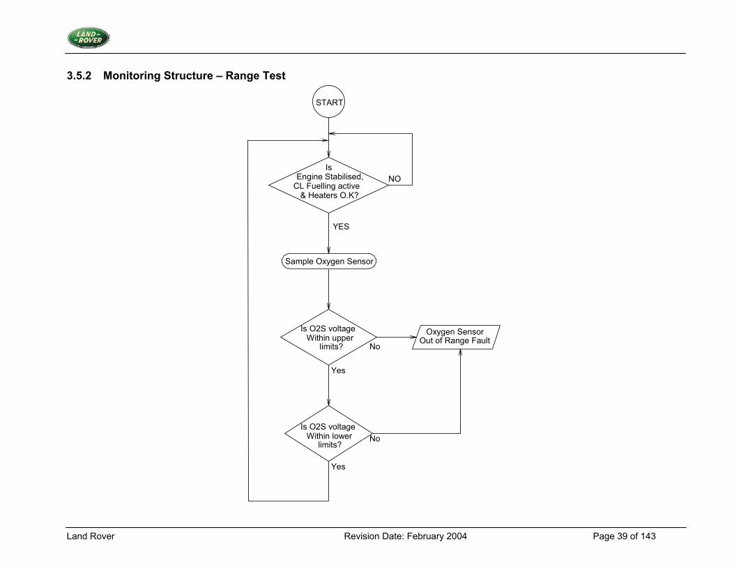
3.5.2 Monitoring Structure – Range Test
START
Engine Stabilised, CL Fuelling active & Heaters O.K?
No
No
Yes
Yes
Sample Oxygen Sensor
Is O2S voltageWithin upper
limits?
Is O2S voltageWithin lower
limits?
YES
NO
Oxygen SensorOut of Range Fault
Is
Land Rover Revision Date: February 2004 Page 40 of 143
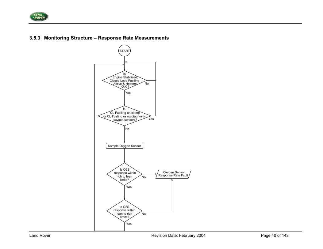
3.5.3 Monitoring Structure – Response Rate Measurements
START
Engine Stabilised, Closed Loop Fuelling
Active & Heaters
Yes
No
Yes
No
Sample Oxygen Sensor
Is O2S response within
rich to leanlimits?
Is O2S response within
lean to richlimits?
Yes
No
Yes
No
Yes
Oxygen SensorResponse Rate Fault
CL Fuelling on clamp or CL Fueling using diagnostic
oxygen sensors?
Is
O.K ?
Is
Land Rover Revision Date: February 2004 Page 41 of 143
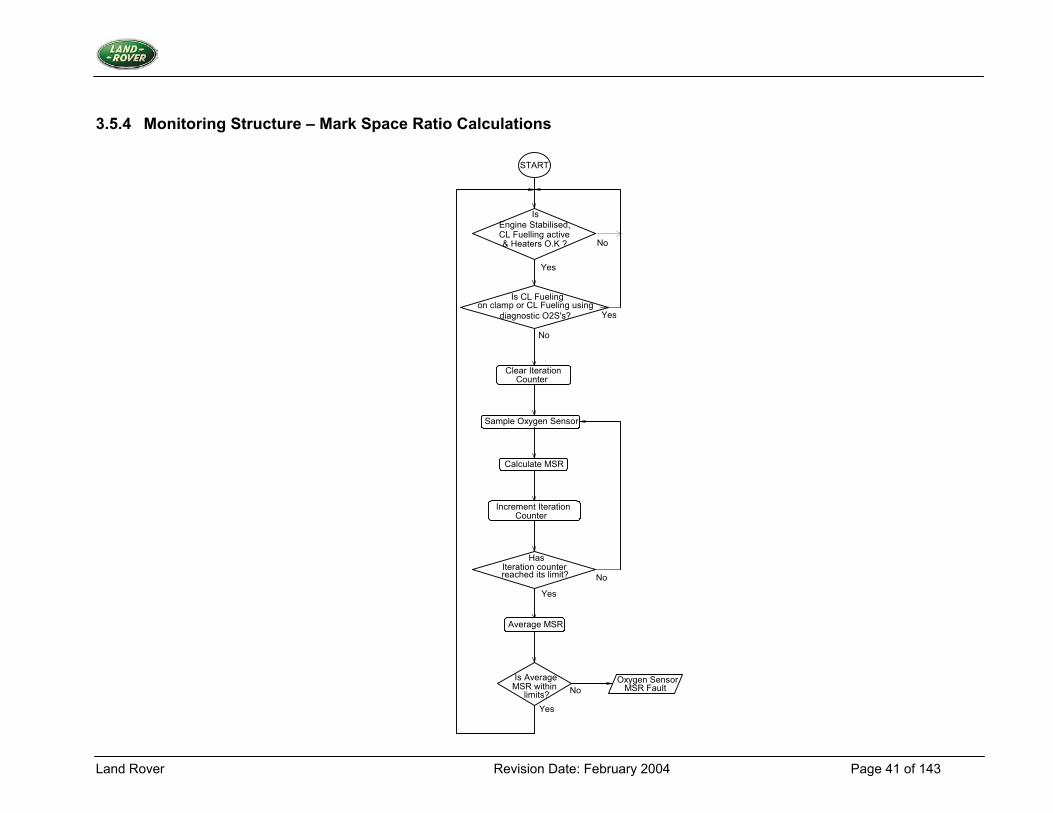
3.5.4 Monitoring Structure – Mark Space Ratio Calculations
START
Engine Stabilised,CL Fuelling active & Heaters O.K ?
Yes
No
Yes
No
Sample Oxygen Sensor
Iteration counter reached its limit? No
Yes
Is AverageMSR within
limits?
Oxygen SensorMSR FaultNo
Yes
Is CL Fueling on clamp or CL Fueling using
diagnostic O2S's?
Clear IterationCounter
Calculate MSR
Increment IterationCounter
Average MSR
Is
Has
Land Rover Revision Date: February 2004 Page 42 of 143
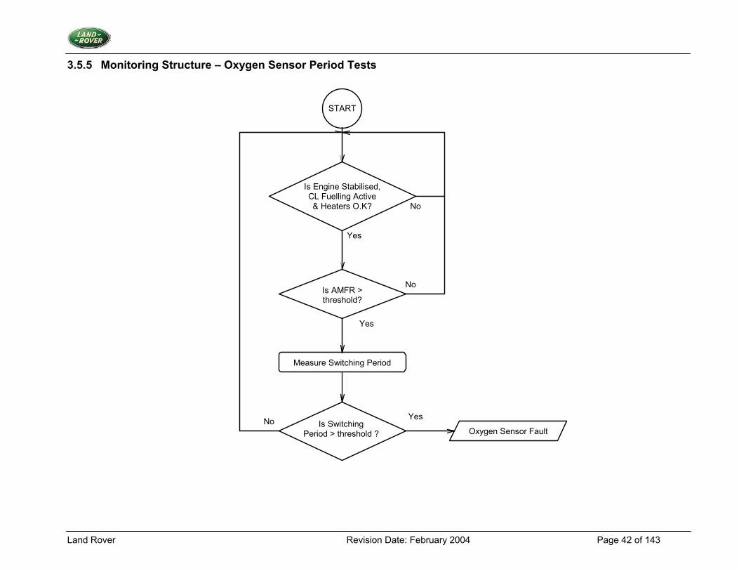
3.5.5 Monitoring Structure – Oxygen Sensor Period Tests
Is Engine Stabilised,CL Fuelling Active & Heaters O.K?
Yes
No
Is AMFR > threshold?
Yes
No
Measure Switching Period
START
YesNo Is Switching Period > threshold ? Oxygen Sensor Fault
Land Rover Revision Date: February 2004 Page 43 of 143
3.5.6 Monitoring Structure – Oxygen Sensor Clamp Tests START
Is Engine Stabilised, CL Fuelling Active & Heaters O.K?
Yes
No
START
Is Engine Stabilised, CL Fuelling Active
& Heaters O.K? No
Yes
Yes
No
Yes
No
Yes
No
Maximum Fuelling change
Permitted?
Yes
No
Yes
PossibleFuelling Fault
No
Is Integrator on Enrichment
Clamp?
Reduce fuelling by Enrich Percent
Is Integrator on Enrichment
Clamp?
Increase fuelling by Extra Percent
Is Integrator on Enrichment
Clamp?
Oxygen Sensor Failed to switch
Rich Fault
Are ECT and Throttle Position above
thresholds?
Wait Test Time Period
Wait Test Time Period
Yes
No
Yes
Is Integrator on Enleanment
Clamp? No
Is Integrator on Enleanment
Clamp?
Yes
No
Reduce fuelling by Extra Percent
MaximumFuelling change
Permitted?
Yes
Oxygen Sensor Failed to switch
Lean Fault
Is Integrator on Enleanment
Clamp? No
Yes
PossibleFuelling Fault
No
Reduce fuelling by Enlean Percent
Are ECT and Throttle Position above
thresholds?
Wait Test Time Period
Wait Test Time Period
Land Rover Revision Date: February 2004 Page 44 of 143
3.5.7 Monitoring Structure - Fuel System Clamp Tests
STAR T
Is Engine Stabilised, CL Fuelling Activ e & Heaters O.K?
Yes
No
Yes
No
No
Yes
Has Integrator mov ed off
Clamp? Yes
No
No
Has Integrator mov ed off
Clamp? Yes
Has Fault Counter reached
limit Yes
Is Fault Counter Zero? Yes
No
No
Clamp Fault Present
Are ECT and throttle position abov e
thresholds?
Is CL Fuelling on clamp or CL Fuelling using
diagnostic oxygen sensor?
Remov e Diagnostic Fuelling Changes
Start Oxygen Sensor Diagnostic Clamp Delay
Increment Fault Counter f rom
Zero
Decrement Fault Counter
Increment Fault Counter
Land Rover Revision Date: February 2004 Page 45 of 143
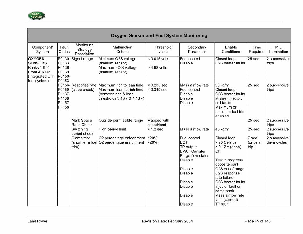
Oxygen Sensor and Fuel System Monitoring
Component/ System
Fault Codes
Monitoring Strategy
Description
Malfunction Criteria
Threshold value
Secondary Parameter
Enable Conditions
Time Required
MIL Illumination
OXYGEN P0130- Signal range Minimum O2S voltage < 0.015 volts Fuel control Closed loop 25 sec 2 successive SENSORS P0133 (titanium sensor) Disable O2S heater faults trips Banks 1 & 2 P0136- Maximum O2S voltage > 4.98 volts Front & Rear P0139 (titanium sensor) (Integrated with P0150- fuel system) P0153 P0156- Response rate Maximum rich to lean time < 0.235 sec Mass airflow rate 90 kg/hr 25 sec 2 successive P0159 (slope check) Maximum lean to rich time < 0.349 sec Fuel control Closed loop trips P1137- (between rich & lean Disable O2S heater faults P1138 thresholds 3.13 v & 1.13 v) Disable Misfire, injector, P1157- Disable coil faults P1158 Maximum or minimum fuel trim enabled Mark Space Outside permissible range Mapped with 25 sec 2 successive Ratio Check speed/load trips Switching High period limit > 1.2 sec Mass airflow rate 40 kg/hr 25 sec 2 successive period check trips Clamp test O2 percentage enleanment >20% Fuel control Closed loop 7 sec 2 successive (short term fuel O2 percentage enrichment >20% ECT > 70 Celsius (once a drive cycles trim) TP output > 0.12 v (open) trip) EVAP Canister Off Purge flow status Disable Test in progress opposite bank Disable O2S out of range Disable O2S response rate failure Disable O2S heater faults Disable Injector fault on same bank Disable Mass airflow rate fault (current) Disable TP fault
Land Rover Revision Date: February 2004 Page 46 of 143
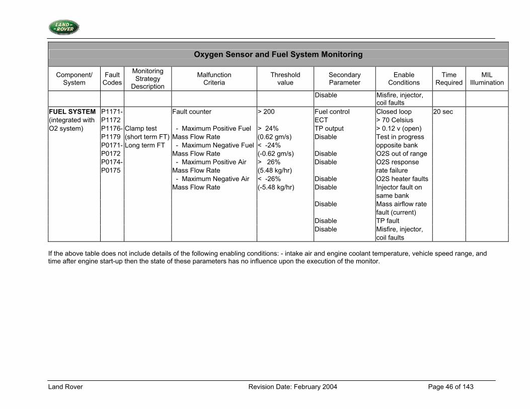
Oxygen Sensor and Fuel System Monitoring
Component/ System
Fault Codes
Monitoring Strategy
Description
Malfunction Criteria
Threshold value
Secondary Parameter
Enable Conditions
Time Required
MIL Illumination
Disable Misfire, injector, coil faults FUEL SYSTEM P1171- Fault counter > 200 Fuel control Closed loop 20 sec (integrated with P1172 ECT > 70 Celsius O2 system) P1176- Clamp test - Maximum Positive Fuel > 24% TP output > 0.12 v (open) P1179 (short term FT) Mass Flow Rate (0.62 gm/s) Disable Test in progress P0171- Long term FT - Maximum Negative Fuel < -24% opposite bank P0172 Mass Flow Rate (-0.62 gm/s) Disable O2S out of range P0174- - Maximum Positive Air > 26% Disable O2S response P0175 Mass Flow Rate (5.48 kg/hr) rate failure - Maximum Negative Air < -26% Disable O2S heater faults Mass Flow Rate (-5.48 kg/hr) Disable Injector fault on same bank Disable Mass airflow rate fault (current) Disable TP fault Disable Misfire, injector, coil faults If the above table does not include details of the following enabling conditions: - intake air and engine coolant temperature, vehicle speed range, and time after engine start-up then the state of these parameters has no influence upon the execution of the monitor.
Land Rover Revision Date: February 2004 Page 47 of 143
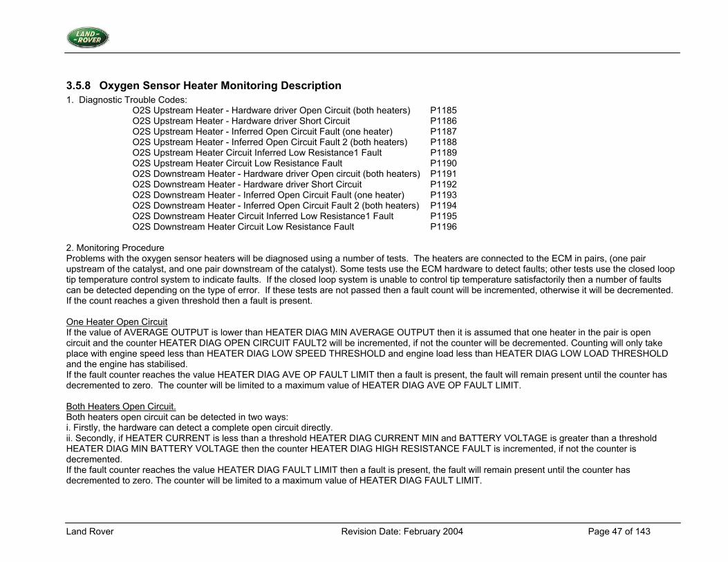
3.5.8 Oxygen Sensor Heater Monitoring Description 1. Diagnostic Trouble Codes:
O2S Upstream Heater - Hardware driver Open Circuit (both heaters) P1185 O2S Upstream Heater - Hardware driver Short Circuit P1186 O2S Upstream Heater - Inferred Open Circuit Fault (one heater) P1187 O2S Upstream Heater - Inferred Open Circuit Fault 2 (both heaters) P1188 O2S Upstream Heater Circuit Inferred Low Resistance1 Fault P1189 O2S Upstream Heater Circuit Low Resistance Fault P1190 O2S Downstream Heater - Hardware driver Open circuit (both heaters) P1191 O2S Downstream Heater - Hardware driver Short Circuit P1192 O2S Downstream Heater - Inferred Open Circuit Fault (one heater) P1193 O2S Downstream Heater - Inferred Open Circuit Fault 2 (both heaters) P1194 O2S Downstream Heater Circuit Inferred Low Resistance1 Fault P1195 O2S Downstream Heater Circuit Low Resistance Fault P1196
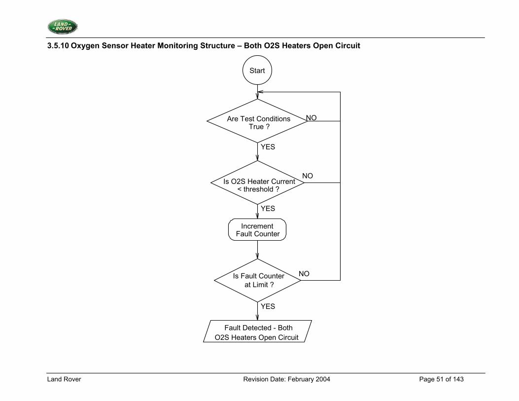
2. Monitoring Procedure Problems with the oxygen sensor heaters will be diagnosed using a number of tests. The heaters are connected to the ECM in pairs, (one pair upstream of the catalyst, and one pair downstream of the catalyst). Some tests use the ECM hardware to detect faults; other tests use the closed loop tip temperature control system to indicate faults. If the closed loop system is unable to control tip temperature satisfactorily then a number of faults can be detected depending on the type of error. If these tests are not passed then a fault count will be incremented, otherwise it will be decremented. If the count reaches a given threshold then a fault is present. One Heater Open Circuit If the value of AVERAGE OUTPUT is lower than HEATER DIAG MIN AVERAGE OUTPUT then it is assumed that one heater in the pair is open circuit and the counter HEATER DIAG OPEN CIRCUIT FAULT2 will be incremented, if not the counter will be decremented. Counting will only take place with engine speed less than HEATER DIAG LOW SPEED THRESHOLD and engine load less than HEATER DIAG LOW LOAD THRESHOLD and the engine has stabilised. If the fault counter reaches the value HEATER DIAG AVE OP FAULT LIMIT then a fault is present, the fault will remain present until the counter has decremented to zero. The counter will be limited to a maximum value of HEATER DIAG AVE OP FAULT LIMIT. Both Heaters Open Circuit. Both heaters open circuit can be detected in two ways: i. Firstly, the hardware can detect a complete open circuit directly. ii. Secondly, if HEATER CURRENT is less than a threshold HEATER DIAG CURRENT MIN and BATTERY VOLTAGE is greater than a threshold HEATER DIAG MIN BATTERY VOLTAGE then the counter HEATER DIAG HIGH RESISTANCE FAULT is incremented, if not the counter is decremented. If the fault counter reaches the value HEATER DIAG FAULT LIMIT then a fault is present, the fault will remain present until the counter has decremented to zero. The counter will be limited to a maximum value of HEATER DIAG FAULT LIMIT.
Land Rover Revision Date: February 2004 Page 48 of 143
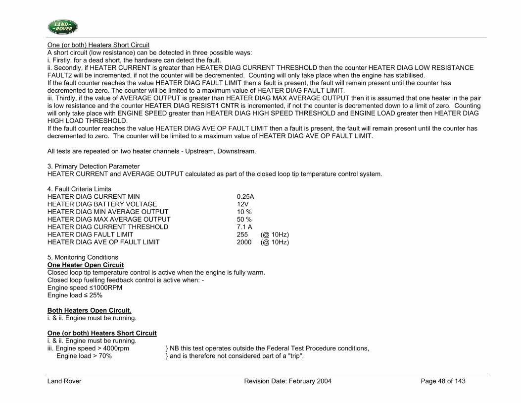
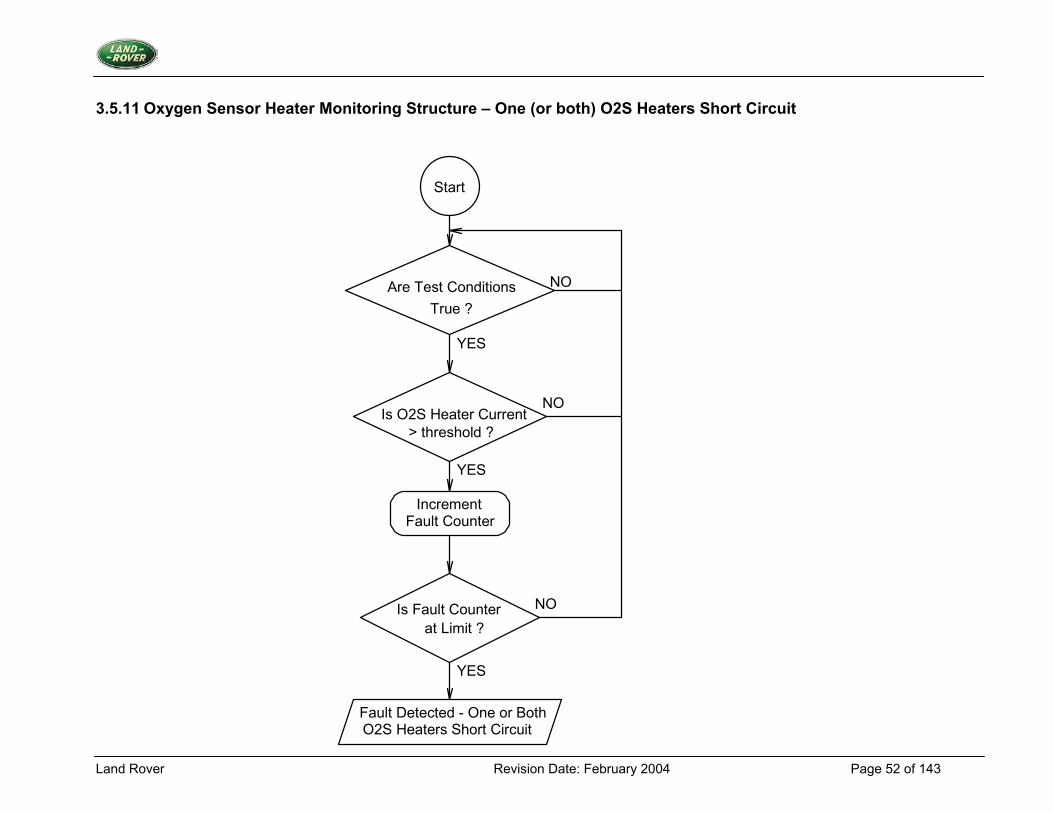
One (or both) Heaters Short Circuit A short circuit (low resistance) can be detected in three possible ways: i. Firstly, for a dead short, the hardware can detect the fault. ii. Secondly, if HEATER CURRENT is greater than HEATER DIAG CURRENT THRESHOLD then the counter HEATER DIAG LOW RESISTANCE FAULT2 will be incremented, if not the counter will be decremented. Counting will only take place when the engine has stabilised. If the fault counter reaches the value HEATER DIAG FAULT LIMIT then a fault is present, the fault will remain present until the counter has decremented to zero. The counter will be limited to a maximum value of HEATER DIAG FAULT LIMIT. iii. Thirdly, if the value of AVERAGE OUTPUT is greater than HEATER DIAG MAX AVERAGE OUTPUT then it is assumed that one heater in the pair is low resistance and the counter HEATER DIAG RESIST1 CNTR is incremented, if not the counter is decremented down to a limit of zero. Counting will only take place with ENGINE SPEED greater than HEATER DIAG HIGH SPEED THRESHOLD and ENGINE LOAD greater then HEATER DIAG HIGH LOAD THRESHOLD. If the fault counter reaches the value HEATER DIAG AVE OP FAULT LIMIT then a fault is present, the fault will remain present until the counter has decremented to zero. The counter will be limited to a maximum value of HEATER DIAG AVE OP FAULT LIMIT. All tests are repeated on two heater channels - Upstream, Downstream. 3. Primary Detection Parameter HEATER CURRENT and AVERAGE OUTPUT calculated as part of the closed loop tip temperature control system. 4. Fault Criteria Limits HEATER DIAG CURRENT MIN 0.25A HEATER DIAG BATTERY VOLTAGE 12V HEATER DIAG MIN AVERAGE OUTPUT 10 % HEATER DIAG MAX AVERAGE OUTPUT 50 % HEATER DIAG CURRENT THRESHOLD 7.1 A HEATER DIAG FAULT LIMIT 255 (@ 10Hz) HEATER DIAG AVE OP FAULT LIMIT 2000 (@ 10Hz) 5. Monitoring Conditions One Heater Open Circuit Closed loop tip temperature control is active when the engine is fully warm. Closed loop fuelling feedback control is active when: - Engine speed ≤1000RPM Engine load ≤ 25% Both Heaters Open Circuit. i. & ii. Engine must be running. One (or both) Heaters Short Circuit i. & ii. Engine must be running. iii. Engine speed > 4000rpm } NB this test operates outside the Federal Test Procedure conditions, Engine load > 70% } and is therefore not considered part of a "trip".
Land Rover Revision Date: February 2004 Page 49 of 143
6. Monitoring Time Length / Frequency of Checks The frequency of the Oxygen Sensor Heater Diagnostic is 10Hz. 7. Criteria for Storing Diagnostic Trouble Code Two successive trips where the Oxygen Sensor Heater Diagnostic indicates a failed Oxygen Sensor Heater. 8. Criteria for Illuminating MIL Two successive trips where the Oxygen Sensor Heater Diagnostic indicates a failed Oxygen Sensor Heater. 9. Criteria for Determining Out of Range Input Signals The input signal is subjected to the diagnostics as above.
Land Rover Revision Date: February 2004 Page 50 of 143
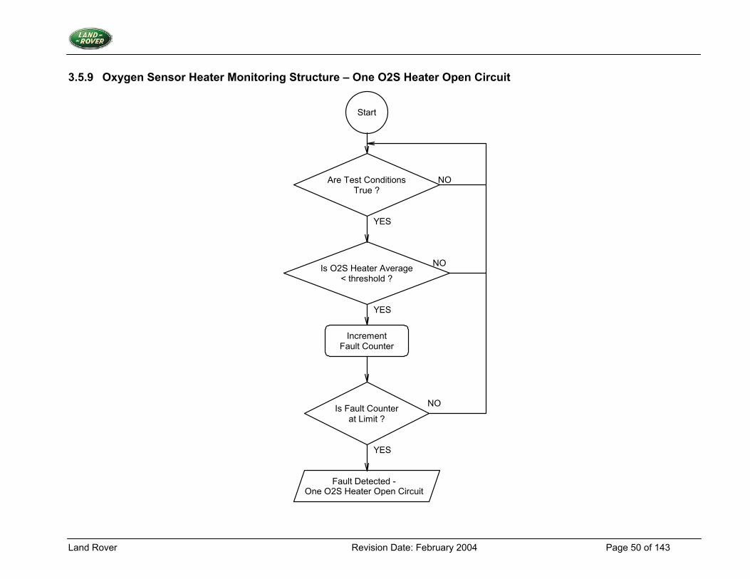
3.5.9 Oxygen Sensor Heater Monitoring Structure – One O2S Heater Open Circuit
Start
Are Test ConditionsTrue ?
Increment Fault Counter
Is Fault Counterat Limit ?
YES
YES
YES
NO
NO
NO
Is O2S Heater Average < threshold ?
Fault Detected - One O2S Heater Open Circuit
Land Rover Revision Date: February 2004 Page 51 of 143
3.5.10 Oxygen Sensor Heater Monitoring Structure – Both O2S Heaters Open Circuit
Start
Are Test ConditionsTrue ?
Increment Fault Counter
Is Fault Counterat Limit ?
YES
YES
YES
NO
NO
NO
Is O2S Heater Current< threshold ?
Fault Detected - BothO2S Heaters Open Circuit
Land Rover Revision Date: February 2004 Page 52 of 143
3.5.11 Oxygen Sensor Heater Monitoring Structure – One (or both) O2S Heaters Short Circuit
Start
Are Test ConditionsTrue ?
Is O2S Heater Current> threshold ?
Increment Fault Counter
Is Fault Counterat Limit ?
Fault Detected - One or BothO2S Heaters Short Circuit
YES
YES
YES
NO
NO
NO
Land Rover Revision Date: February 2004 Page 53 of 143
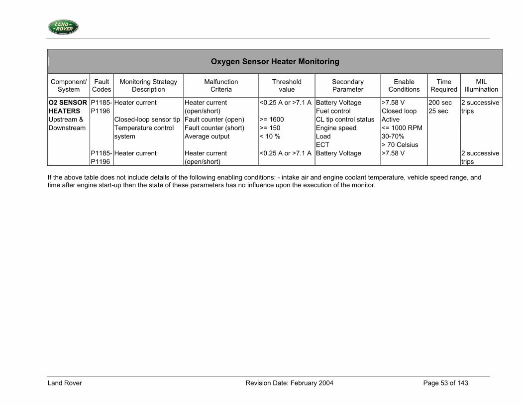
Oxygen Sensor Heater Monitoring
Component/ System
Fault Codes
Monitoring Strategy Description
Malfunction Criteria
Threshold value
Secondary Parameter
Enable Conditions
Time Required
MIL Illumination
O2 SENSOR P1185- Heater current Heater current <0.25 A or >7.1 A Battery Voltage >7.58 V 200 sec 2 successive HEATERS P1196 (open/short) Fuel control Closed loop 25 sec trips Upstream & Closed-loop sensor tip Fault counter (open) >= 1600 CL tip control status Active Downstream Temperature control Fault counter (short) >= 150 Engine speed <= 1000 RPM system Average output < 10 % Load 30-70% ECT > 70 Celsius P1185- Heater current Heater current <0.25 A or >7.1 A Battery Voltage >7.58 V 2 successive P1196 (open/short) trips If the above table does not include details of the following enabling conditions: - intake air and engine coolant temperature, vehicle speed range, and time after engine start-up then the state of these parameters has no influence upon the execution of the monitor.
Land Rover Revision Date: February 2004 Page 54 of 143
3.6 Fuel Tank Pressure Sensor Monitor
3.6.1 Description 1. Diagnostic Trouble Codes:
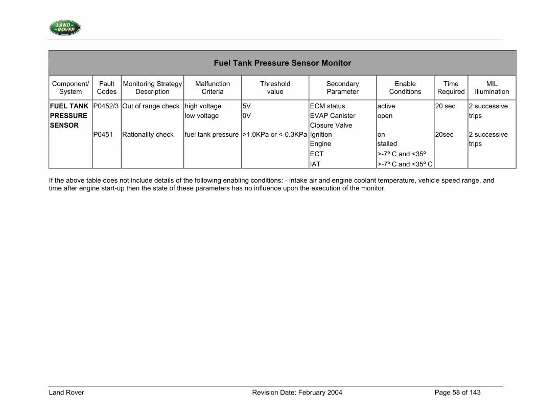
Fuel tank pressure sensor low fault: P0452 Fuel tank pressure sensor high fault: P0453 Fuel tank pressure sensor performance fault: P0451
2. Monitoring Procedure Summary The resistance of the fuel tank pressure sensor changes in relation to the pressure difference between the fuel tank and ambient pressure. Through connection to the input resistor networks of the ECM any disconnection of the sensor can generate both high and low input voltages, which are outside the normal operating voltage range. These are detected to diagnose a fuel tank pressure fault in the system.
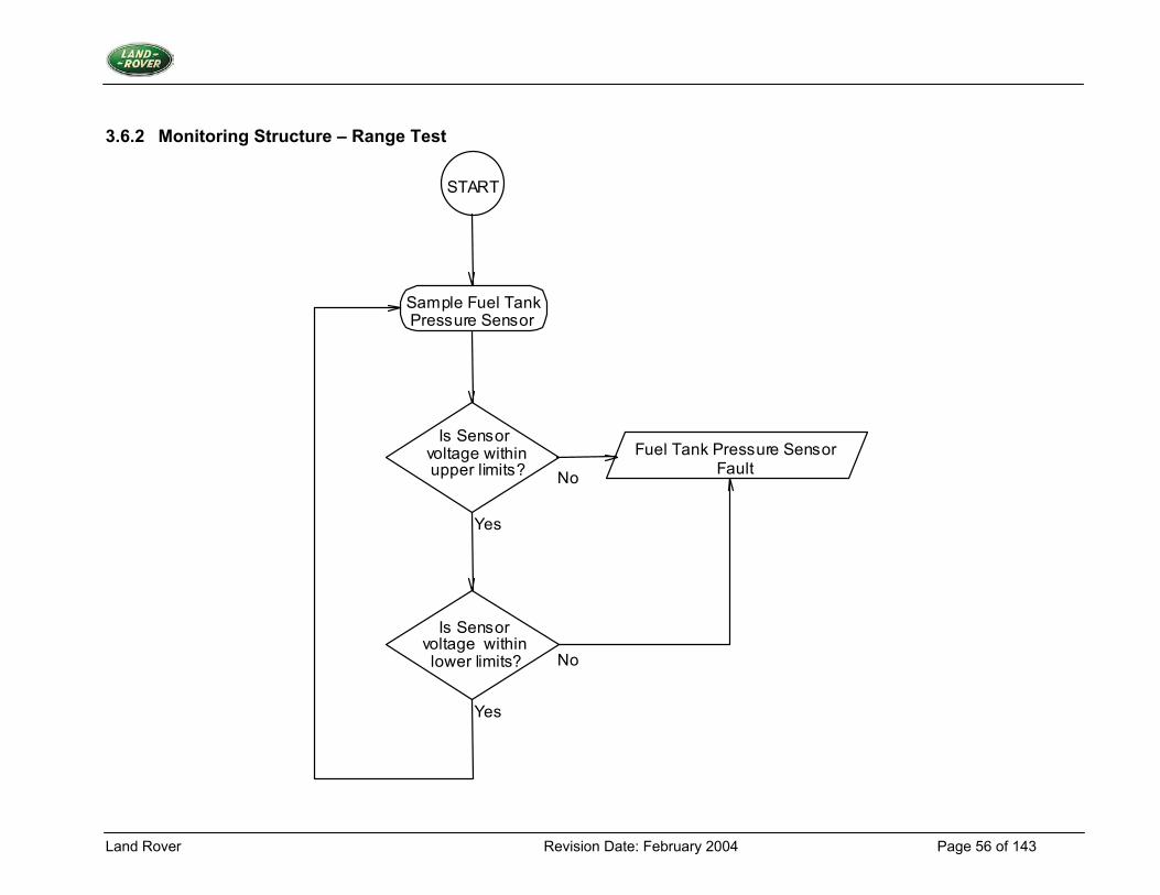
Range Test If the value of FUEL TANK PRESS VOLTS is less than FUEL TANK PRESS DIAG MIN VOLT THR or more than FUEL TANK PRESS DIAG MAX VOLT THR, then an appropriate fault counter is incremented up to a limit of fuel tank pressure diagnostic fault limit. Otherwise the fault counter is decremented down to a limit of zero. If the fault counter reaches the limit then a fuel tank pressure sensor fault is present.
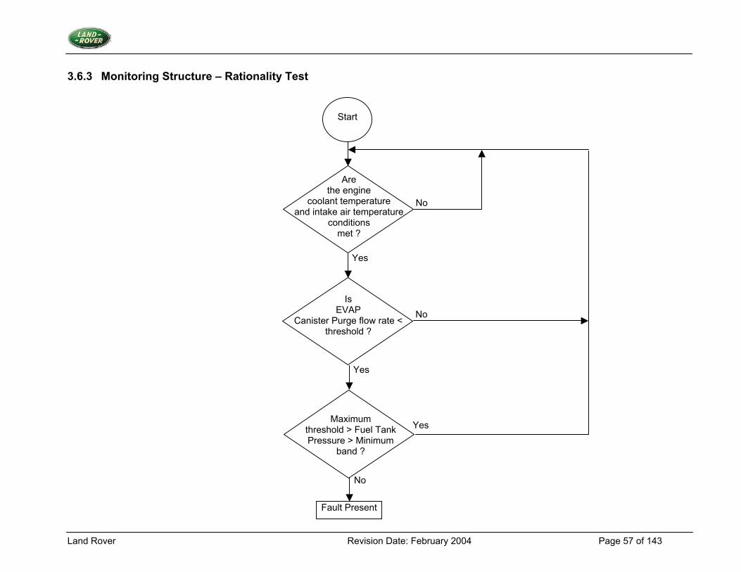
Rationality Test The test on the fuel tank pressure sensor comprises of comparing the output from the fuel tank pressure sensor with a tolerance band around ambient pressure. This is done during conditions of minimal vapour generation within the fuel tank. 3. Primary Detection Parameter Fuel tank pressure - Measured in volts, the outcome of a potential divider calculation. 4. Fault Criteria Limits Fuel Tank Pressure - Low out of range 0V Fuel Tank Pressure - High out of range 6V Error between fuel tank pressure and ambient pressure > 1 kPa or < -0.3 kPa 5. Monitoring Conditions The range test will take place when the EVAP canister closure valve is open. The rationality check will take place when the engine coolant temperature is between two thresholds, intake air temperature is between two thresholds, EVAP canister purge flow rate is below a threshold and the EVAP canister closure valve is open. 6. Monitoring Time Length / Frequency of Checks The frequency of the fuel tank pressure diagnostic is 40Hz. 7. Criteria for Storing Fault Code Two successive trips where the fuel tank pressure diagnostic indicates a failed fuel tank pressure sensor.
Land Rover Revision Date: February 2004 Page 55 of 143
8. Criteria for Illuminating MIL Two successive trips where the fuel tank pressure diagnostic indicates a failed fuel tank pressure sensor. 9. Criteria for Determining Out of Range Input Signals The fuel tank pressure sensor is subject to the range test above.
Land Rover Revision Date: February 2004 Page 56 of 143
3.6.2 Monitoring Structure – Range Test
START
No
No
Yes
Yes
Sample Fuel Tank Pressure Sensor
Is Sensor voltage within upper limits?
Is Sensor voltage within lower limits?
Fuel Tank Pressure Sensor Fault
Land Rover Revision Date: February 2004 Page 57 of 143
3.6.3 Monitoring Structure – Rationality Test
Start
Are the engine
coolant temperature and intake air temperature
conditions met ?
Is EVAP
Canister Purge flow rate < threshold ?
Maximum
threshold > Fuel Tank Pressure > Minimum
band ?
Fault Present
No
Yes
No
No
Yes
Yes
Land Rover Revision Date: February 2004 Page 58 of 143
Fuel Tank Pressure Sensor Monitor
Component/ System
Fault Codes
Monitoring StrategyDescription
Malfunction Criteria
Threshold value
Secondary Parameter
Enable Conditions
Time Required
MIL Illumination
FUEL TANK P0452/3 Out of range check high voltage 5V ECM status active 20 sec 2 successive PRESSURE low voltage 0V EVAP Canister open trips SENSOR Closure Valve P0451 Rationality check fuel tank pressure >1.0KPa or <-0.3KPa Ignition on 20sec 2 successive Engine stalled trips ECT >-7º C and <35º IAT >-7º C and <35º C If the above table does not include details of the following enabling conditions: - intake air and engine coolant temperature, vehicle speed range, and time after engine start-up then the state of these parameters has no influence upon the execution of the monitor.
Land Rover Revision Date: February 2004 Page 59 of 143
3.7 Crankshaft and Camshaft Position Sensor
3.7.1 Description 1. Diagnostic Trouble Codes:
Crankshaft Position Sensor Circuit Malfunction P0335 Crankshaft Position Sensor Range/Performance P0336 Camshaft Position Sensor Circuit Malfunction P0340
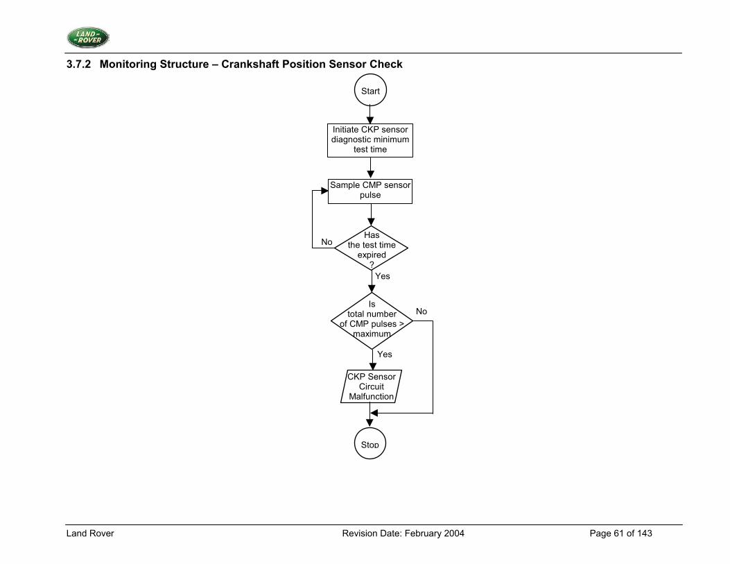
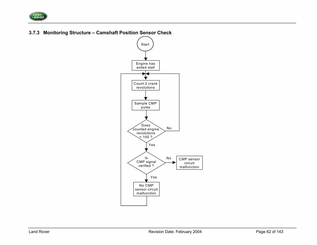
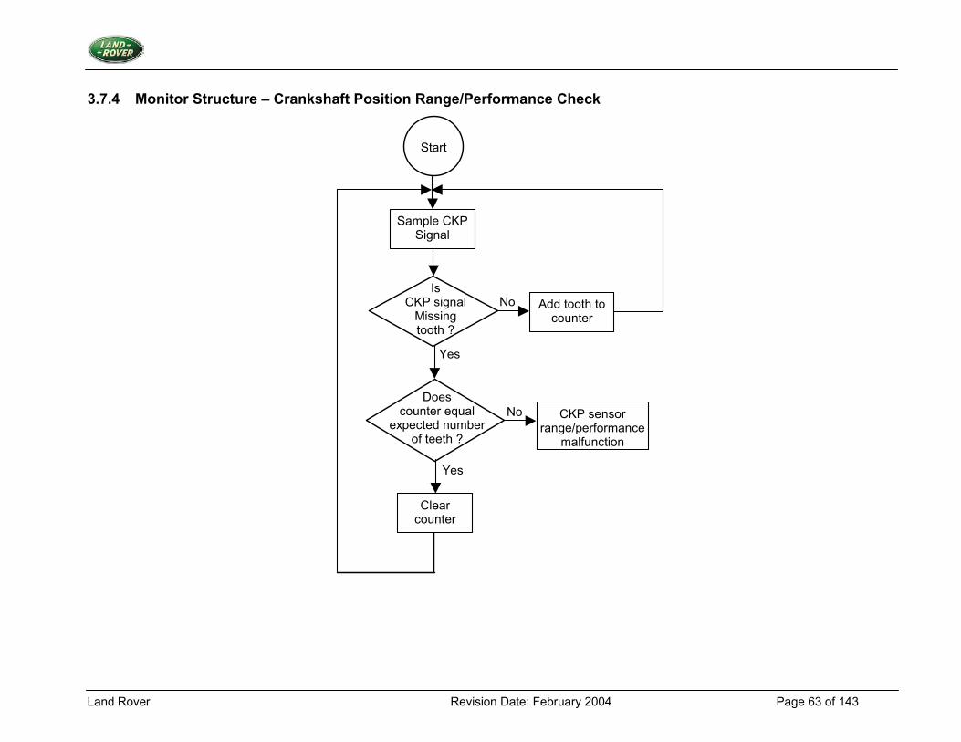
2. Monitoring Procedure Summary Problems with the crankshaft and camshaft position sensors will be detected by cross - checking each sensor's output, identifying when one sensor is operating and the other is not. A missing tooth check will test that all tooth edges are being correctly detected and that there is a missing tooth present. As the crankshaft speed sensor is central to engine management system operation there is no default operation, which would allow the car to run when there is a crankshaft position sensor circuit malfunction. Crankshaft Position Sensor Check If more than CRANK DIAG MAX CAM PULSES camshaft position sensor pulses are detected during CRANK DIAG MIN TEST TIME, while the engine is in STALL, then a crankshaft position sensor fault is present. When the engine enters CRANKING mode, implying the crankshaft position sensor is operational, there is no crankshaft position sensor circuit malfunction present. Camshaft Position Sensor Check If CRANK DIAG MIN CRANK REVS crankshaft revolutions occur from exiting STALL conditions, without CAM SIGNAL VERIFIED being detected, then there is a camshaft position sensor fault present. There is no fault present if CAM SIGNAL VERIFIED is detected on every engine revolution for CRANK DIAG MIN ENG REVS. Crankshaft Range / Performance Check Missing teeth are expected to be NO OF TEETH ON WHEEL crankshaft teeth apart. If the number of crankshaft position inaccurate fault event occurs then the fault event counter should be incremented by one, up to a limit of CRANK DIAG FAULT LIMIT. Every time the tooth count equals the actual number of teeth between missing teeth then decrement the fault event counter by one, down to a limit of zero. If the fault event count reaches CRANK DIAG FAULT LIMIT then there is a crankshaft position inaccurate fault present. There is no fault present only when the fault event counter reaches zero. The fault event counter is cleared to zero at the start of a trip. 3. Primary Detection Parameter Crankshaft Position Sensor – Crankshaft Position sensor signal edges. Camshaft Position Sensor – Camshaft Position sensor signal edges. 4. Fault Criteria Limits General - presence or not of sensor edges.
Land Rover Revision Date: February 2004 Page 60 of 143
Crankshaft Position Sensor Check The non-existence of at least 6 CRANK DIAG MAX CAM PULSES within the minimum CRANK DIAG MIN TEST TIME period of 9 seconds. Indicating an average speed of 80 rpm. Camshaft Position Sensor Check The non-setting of the Camshaft Position signal verified flag within the limit of CRANK DIAG MIN CRANK REVS' 100 revolutions. Crankshaft Range / Performance Check NO OF TEETH ON WHEEL constant is dependent upon the sensor wheel design (35 teeth), a fault is registered if the tooth count total between missing teeth is out by one or more. 5. Monitoring Conditions The crankshaft position sensor check will be run if the engine is in stall. The camshaft position sensor check will be run if the engine has exited stall and battery voltage is greater than 8V. The missing tooth position check will run when the engine is running. 6. Monitoring Time Length / Frequency of Checks The crankshaft position sensor check will be run if the engine is in stall. The camshaft position sensor check will be run if the engine has exited stall. The missing tooth position check will be run once every engine revolution. 7. Criteria for Storing a Diagnostic Trouble Code Two successive trips where the diagnostic routines indicate a failed crank or cam sensor. 8. Criteria for Illuminating MIL Two successive trips where the diagnostic routines indicate a failed crank or cam sensor. 9. Criteria for Determining Out of Range Input Signals The crank / cam sensors produce non-linear outputs; the criteria will be signal/no signal.
Land Rover Revision Date: February 2004 Page 61 of 143
3.7.2 Monitoring Structure – Crankshaft Position Sensor Check
Start
No
Yes
Yes
No
Stop
Initiate CKP sensor diagnostic minimum
test time
Sample CMP sensor pulse
Has the test time
expired ?
Is total number
of CMP pulses > maximum
CKP Sensor Circuit
Malfunction
Land Rover Revision Date: February 2004 Page 62 of 143
3.7.3 Monitoring Structure – Camshaft Position Sensor Check
Start
Yes
Yes
No
No
Engine has exited stall
Sample CMP pulse
Count 2 crank revolutions
Does counted engine
revolutions = 100 ?
Is CMP signal
verified ?
CMP sensor circuit
malfunction
No CMP sensor circuit malfunction
Land Rover Revision Date: February 2004 Page 63 of 143
3.7.4 Monitor Structure – Crankshaft Position Range/Performance Check
Start
No
Yes
Yes
Sample CKP Signal
Is CKP signal
Missing tooth ?
Add tooth to counter
Does counter equal
expected number of teeth ?
No CKP sensor range/performance
malfunction
Clear counter
Land Rover Revision Date: February 2004 Page 64 of 143
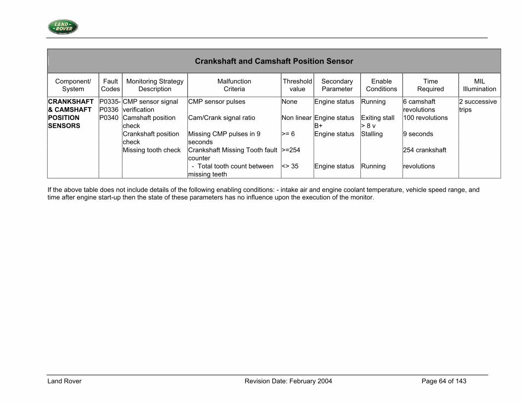
Crankshaft and Camshaft Position Sensor
Component/ System
Fault Codes
Monitoring Strategy Description
Malfunction Criteria
Threshold value
Secondary Parameter
Enable Conditions
Time Required
MIL Illumination
CRANKSHAFT P0335- CMP sensor signal CMP sensor pulses None Engine status Running 6 camshaft 2 successive & CAMSHAFT P0336 verification revolutions trips POSITION P0340 Camshaft position Cam/Crank signal ratio Non linear Engine status Exiting stall 100 revolutions SENSORS check B+ > 8 v Crankshaft position Missing CMP pulses in 9 >= 6 Engine status Stalling 9 seconds check seconds Missing tooth check Crankshaft Missing Tooth fault >=254 254 crankshaft counter - Total tooth count between <> 35 Engine status Running revolutions missing teeth If the above table does not include details of the following enabling conditions: - intake air and engine coolant temperature, vehicle speed range, and time after engine start-up then the state of these parameters has no influence upon the execution of the monitor.
Land Rover Revision Date: February 2004 Page 65 of 143
3.8 Engine Coolant Temperature Sensor
3.8.1 Description 1. Diagnostic Trouble Codes:
Engine Coolant Temperature Sensor - Low out of range P0117 Engine Coolant Temperature Sensor - High out of range P0118 Engine Coolant Temperature Sensor - Warm up time fault P0125 Engine Coolant Temperature Sensor - Falling temperature fault P0116
2. Monitoring Procedure Problems with the engine coolant temperature sensor will be detected using a number of tests. A range check will test for input values outside expected limits. A time to warm-up test will check that the sensor is responding to the rise in engine coolant temperature caused by the engine running. The engine coolant temperature in stall is used to index a map of expected warm-up times. This checks that the engine has gone into closed loop fuelling within a given time, (the engine coolant information is the only sensor it depends upon). A falling temperature test will check for abnormal falls in temperature once a temperature rise has been detected. This test uses a tracker which follows the normal engine coolant temperature rise but at a lower temperature. The tracker is not allowed to decrease and is limited at a maximum value. If the measure engine coolant temperature falls below the tracker a fault is flagged. If the range tested is not passed then the appropriate fault count will be incremented, otherwise it will be decremented. If the count reaches a given threshold then a fault is present. 3. Primary Detection Parameter Engine Coolant Temperature - measured in Volts, the outcome of a potential divider calculation. 4. Fault Criteria Limits Engine Coolant Temperature - Low out of range 0.059 V - equivalent to 145oC Engine Coolant Temperature - High out of range 4.922 V - equivalent to –40oC Engine Coolant Temperature - Warm up time limit, [closed loop fuel] typically 90 seconds at 20oC start temperature Engine Coolant Temperature - Falling temperature tracking limit 650C Engine Coolant Temperature - Warm up temperature 180C Engine Coolant Temperature -Tracker Lag 250C 5. Monitoring Conditions The range check will take place whenever there is power to the ECM. The warm-up time test will start each time the condition 'Engine_Running' is true. The falling temperature test will start each time the condition 'Engine_Running' is true. 6. Monitoring Time Length / Frequency of Checks The frequency of the Engine Coolant Thermistor diagnostic is 2Hz. 7. Criteria for Storing a Diagnostic Trouble Code Two successive trips where the Engine Coolant Thermistor diagnostic indicates a failed water temperature sensor.
Land Rover Revision Date: February 2004 Page 66 of 143
8. Criteria for Illuminating MIL Two successive trips where the engine coolant thermistor diagnostic indicates a failed water temperature sensor. 9. Criteria for Determining Out of Range Input Signals The engine coolant temperature thermistor is subject to maximum and minimum voltage limits of 0.211 V and 4.912 V respectively.
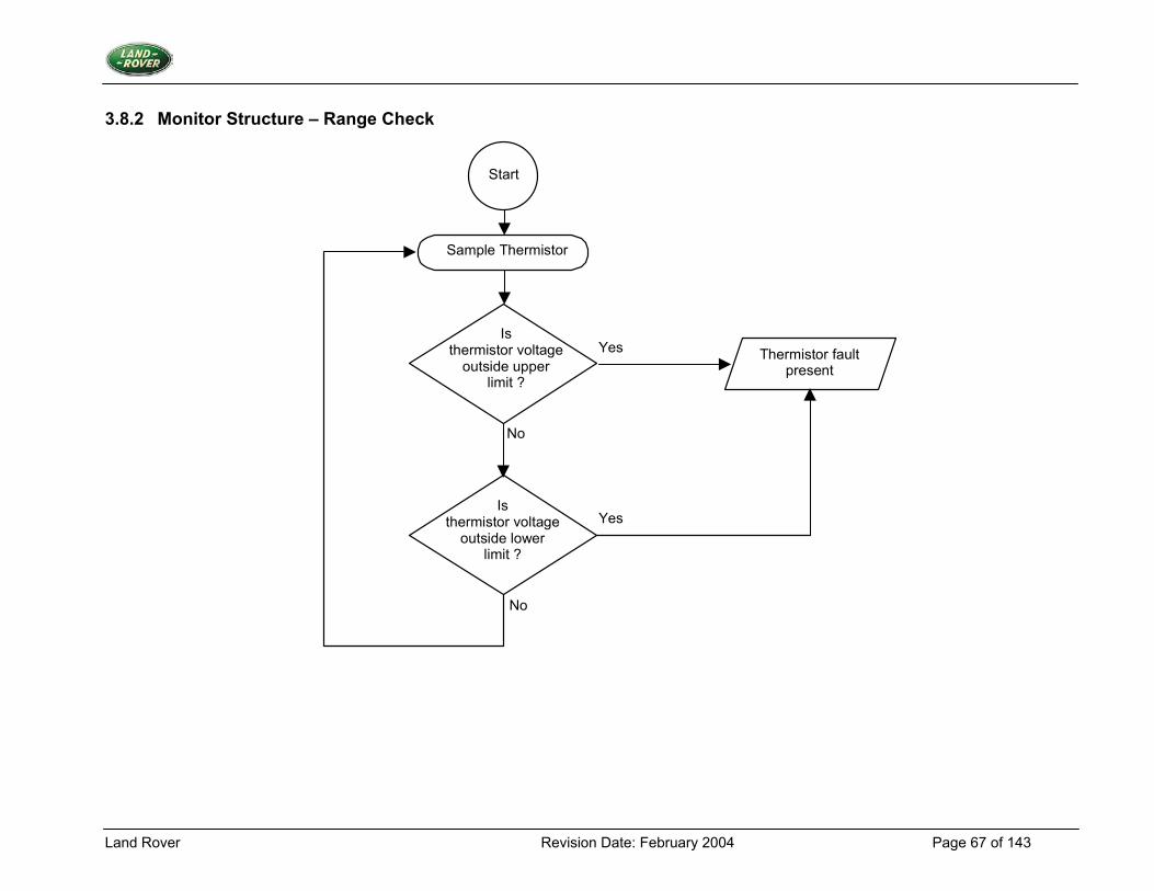
Land Rover Revision Date: February 2004 Page 67 of 143
3.8.2 Monitor Structure – Range Check
Sample Thermistor
Thermistor fault present
Start
Is thermistor voltage
outside upper limit ?
Is thermistor voltage
outside lower limit ?
Yes
Yes
No
No
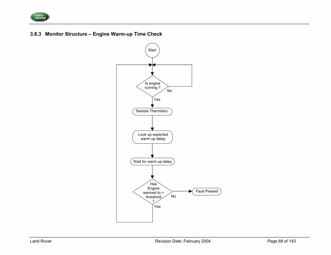
Land Rover Revision Date: February 2004 Page 68 of 143
3.8.3 Monitor Structure – Engine Warm-up Time Check
Start
Is engine running ?
Sample Thermistor
Yes
No
No
Yes
Has Engine
warmed to > threshold
?
Fault Present
Wait for warm up delay
Look up expected warm up delay
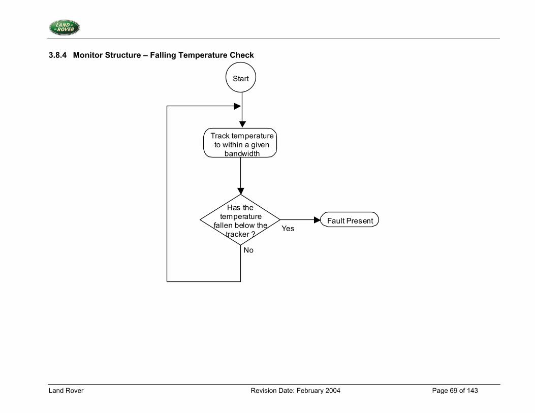
Land Rover Revision Date: February 2004 Page 69 of 143
3.8.4 Monitor Structure – Falling Temperature Check
Start
Track temperature to within a given
bandwidth
Has the temperature
fallen below the tracker ?
Fault Present
No
Yes
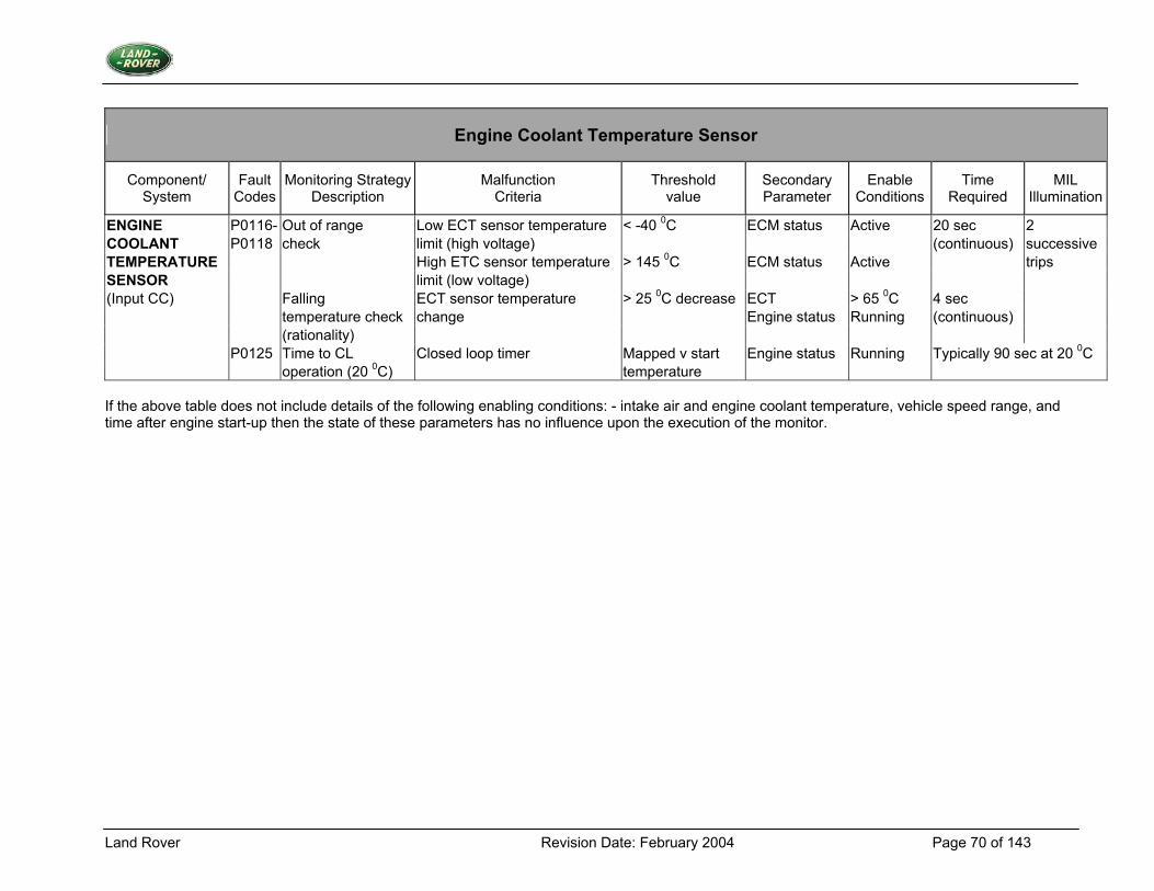
Land Rover Revision Date: February 2004 Page 70 of 143
Engine Coolant Temperature Sensor
Component/ System
Fault Codes
Monitoring StrategyDescription
Malfunction Criteria
Threshold value
Secondary Parameter
Enable Conditions
Time Required
MIL Illumination
ENGINE P0116- Out of range Low ECT sensor temperature < -40 0C ECM status Active 20 sec 2 COOLANT P0118 check limit (high voltage) (continuous) successive TEMPERATURE High ETC sensor temperature > 145 0C ECM status Active trips SENSOR limit (low voltage) (Input CC) Falling ECT sensor temperature > 25 0C decrease ECT > 65 0C 4 sec temperature check change Engine status Running (continuous) (rationality) P0125 Time to CL Closed loop timer Mapped v start Engine status Running Typically 90 sec at 20 0C operation (20 0C) temperature If the above table does not include details of the following enabling conditions: - intake air and engine coolant temperature, vehicle speed range, and time after engine start-up then the state of these parameters has no influence upon the execution of the monitor.
Land Rover Revision Date: February 2004 Page 71 of 143
3.9 Mass Airflow Sensor
3.9.1 Description 1. Diagnostic Trouble Code:
Mass Airflow Circuit - Low Input P0102 Mass Airflow Circuit - High Input P0103 Mass Airflow Circuit Range / Performance Problem P0101
2. Monitoring Procedure Summary Faults with the mass airflow sensor will be detected using three tests. A low range check will look for out of range values. Faults will be detected if the following circumstances are present, no signal (open circuit) at any time with the engine running, or high signal output below a given engine speed. An additional low signal check is performed with the throttle angle and engine speed above threshold values. Low Range Check The average value of the mass airflow sensor voltage is compared to lower limits (AIRFLOW DIAG AFM MIN VOLTAGE) when the engine is running. If the voltage is less than this limit then a counter is incremented, otherwise it is decremented. If the counter reaches a threshold limit, then a fault is present. High Signal Check The average value of the mass airflow sensor voltage is compared to an upper limit (AIRFLOW DIAG AFM MAX VOLTAGE) when the engine speed below a threshold (AIRFLOW DIAG AFM TEST SPEED). If the voltage is greater than this limit then a counter is incremented, otherwise it is decremented. If the counter reaches a threshold limit, then a fault is present. Low Signal Check A low signal test will check for a mass airflow sensor output consistent with other engine parameters. If the airflow meter gives a low signal when both throttle angle and engine speed are above thresholds (AIRFLOW DIAG THANG THRESH & AIRFLOW DIAG SPEED THRESH respectively), then a fault is present. If the tests are not passed then the appropriate fault counter, (AIRFLOW DIAG FAULT LIMIT), will be incremented, otherwise it will be decremented. If the count exceeds a given threshold then a fault is present. 3. Primary Detection Parameter Airflow sensor signal voltage - measured at the ECM input. 4. Fault Criteria Limits Mass airflow sensor - Low out of range 350mV Mass airflow sensor - High rationality limit 4.5V Mass airflow sensor - Low rationality limit 1.1V
Land Rover Revision Date: February 2004 Page 72 of 143
5. Monitoring Conditions The low range check will take place whenever the engine is running; the high signal check will take place when the engine speed is below a given threshold. The low signal check occurs when the throttle angle and engine speed are above respective thresholds. AIRFLOW DIAG AFM TEST SPEED, the maximum engine speed for the high signal check, 1000 rpm. AIRFLOW DIAG THANG THRESH, the absolute throttle potentiometer volts, must be above 2.5V. AIRFLOW DIAG SPEED THRESH, the minimum engine speed for the low signal test, 1500 rpm. AIRFLOW DIAG FAULT LIMIT, the amount of fault events required to flag a fault, 40. The Low Signal Check is inhibited whenever there is a fault present with the throttle position input 6. Monitoring Time Length / Frequency of Checks The frequency of the mass airflow sensor Diagnostic is 10Hz, throughout all engine-operating conditions. 7. Criteria for Storing a Diagnostic Trouble Code Two successive trips where the mass airflow sensor diagnostic indicates a failed mass airflow sensor. 8. Criteria for Illuminating MIL Two successive trips where the mass airflow sensor diagnostic indicates a failed mass airflow sensor. 9. Criteria for Determining Out of Range Input Signals The mass airflow meter voltage is range tested as described above. The engine speed signal is checked for the correct number of teeth on the wheel between missing teeth. The throttle angle input is subject to maximum & minimum range checks.
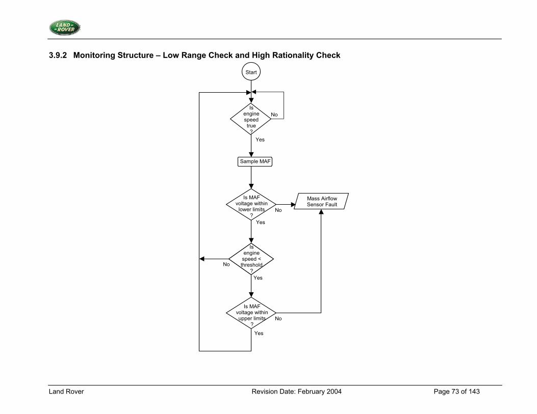
Land Rover Revision Date: February 2004 Page 73 of 143
3.9.2 Monitoring Structure – Low Range Check and High Rationality Check
Start
Yes
Is engine speed true
?
Sample MAF
Is MAF voltage within
lower limits ?
Mass Airflow Sensor Fault
Yes
No
No
Is engine
speed < threshold
? No
Is MAF voltage withinupper limits
?
No
Yes
Yes
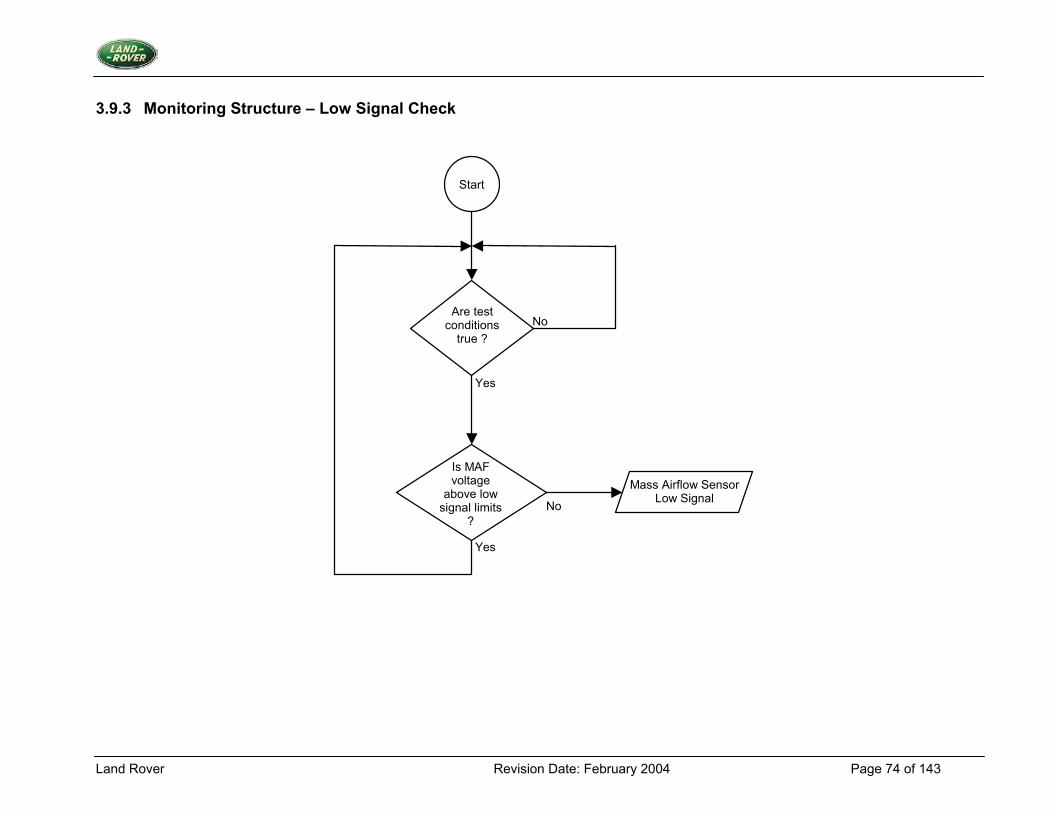
Land Rover Revision Date: February 2004 Page 74 of 143
3.9.3 Monitoring Structure – Low Signal Check
Start
Are test conditions
true ?
Yes
No
Is MAF voltage
above low signal limits
?
Mass Airflow Sensor Low Signal
No
Yes
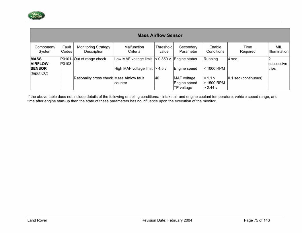
Land Rover Revision Date: February 2004 Page 75 of 143
Mass Airflow Sensor
Component/ System
Fault Codes
Monitoring Strategy Description
Malfunction Criteria
Thresholdvalue
Secondary Parameter
Enable Conditions
Time Required
MIL Illumination
MASS P0101- Out of range check Low MAF voltage limit < 0.350 v Engine status Running 4 sec 2 AIRFLOW P0103 successive SENSOR High MAF voltage limit > 4.5 v Engine speed < 1000 RPM trips (Input CC) Rationality cross check Mass Airflow fault 40 MAF voltage < 1.1 v 0.1 sec (continuous) counter Engine speed > 1500 RPM TP voltage > 2.44 v
If the above table does not include details of the following enabling conditions: - intake air and engine coolant temperature, vehicle speed range, and time after engine start-up then the state of these parameters has no influence upon the execution of the monitor.
Land Rover Revision Date: February 2004 Page 76 of 143
3.10 Intake Air Temperature Sensor
3.10.1 Description 1. Diagnostic Trouble Codes:
Intake Air Temperature Circuit Low Input P0112 Intake Air Temperature Circuit High Input P0113 Intake Air Temperature Sensor Rationality Check P0111
2. Monitoring Procedure Range Check Problems with the intake air temperature sensor are detected using a range test. The range test tests for input values outside expected limits. If the range tested is not passed then the appropriate fault count will be incremented, otherwise it will be decremented. If the counter reaches a given threshold then a fault is present. While fault counting is in progress a back-up value of intake air temperature will be supplied to avoid problems of incorrect values reaching the rest of the system. Rationality Check Once the engine coolant temperature has stabilised hot, the output of the intake air temperature sensor is compared at low and high airflow conditions. The test relies on the fact that the under bonnet temperature causes the intake air temperature to rise at idle compared to high airflow conditions, where the real external ambient temperature is being read. These tests will check that the sensor is correctly mounted and connected. The tests are two-sided, but only one flow chart has been shown. 3. Primary Detection Parameter Intake Air Temperature - measured as thermistor voltage. 4. Fault Criteria Limits Intake Air Temperature Circuit Low Input 0.059V - equivalent to 145oC Intake Air Temperature Circuit High Input 4.922V - equivalent to –40oC Intake Air Temperature rise/fall during rationality check approx 3oC 5. Monitoring Conditions The range check will take place whenever there is power to the ECM. For the rationality check, the following conditions must be met in consecutive order: i. engine coolant temperature is above a threshold (70oC). ii. engine operates at a constant mass airflow rate for a period of time. iii. the average mass airflow rate changes at a certain rate. iv. engine maintains the new mass airflow rate for the period of time that the sensor output test is being conducted. If any of the conditions fail to be true, the test is restarted. 6. Monitoring Time Length / Frequency of Checks The frequency of the Air Thermistor Diagnostic is 2Hz.
Land Rover Revision Date: February 2004 Page 77 of 143
The rationality check will take place at least once per trip. 7. Criteria for Storing a Diagnostic Trouble Code Two successive trips where the air thermistor diagnostic indicates a failed intake air temperature sensor. 8. Criteria for Illuminating MIL Two successive trips where the air thermistor diagnostic indicates a failed intake air temperature sensor. 9. Criteria for Determining Out of Range Input Signals Range check as above.
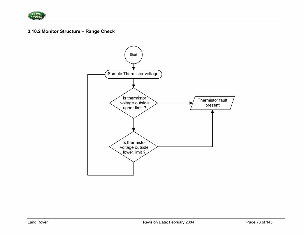
Land Rover Revision Date: February 2004 Page 78 of 143
3.10.2 Monitor Structure – Range Check
Start
Sample Thermistor voltage
Is thermistor voltage outside
upper limit ?
Is thermistor voltage outside
lower limit ?
Thermistor fault present
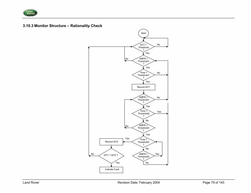
Land Rover Revision Date: February 2004 Page 79 of 143
3.10.3 Monitor Structure – Rationality Check
IAT1 ? IAT2 ?
Time > Threshold2
?
ECT > Threshold
?
AMFR < Threshold1
?
Time > Threshold1
?
AMFR > Threshold1
?
Record IAT1
Time ? Threshold3
?
AMFR > Threshold2
?
Record IAT2
Indicate Fault
Start
No
Yes
No
Yes
Yes
Yes
Yes
No
Yes
No
No
No
Yes
No
Yes
Yes
No
No
AMFR < Threshold2
?
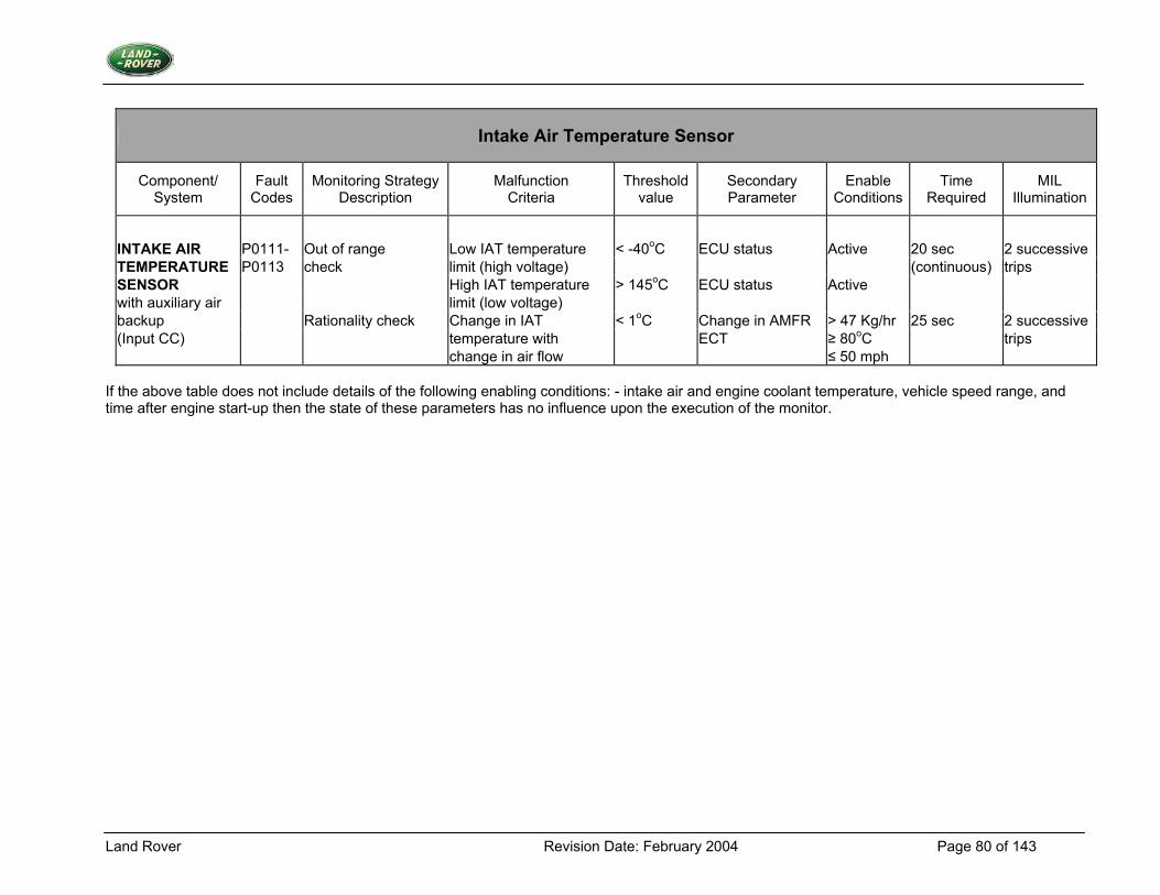
Land Rover Revision Date: February 2004 Page 80 of 143
Intake Air Temperature Sensor
Component/ System
Fault Codes
Monitoring Strategy Description
Malfunction Criteria
Threshold value
Secondary Parameter
Enable Conditions
Time Required
MIL Illumination
INTAKE AIR P0111- Out of range Low IAT temperature < -40oC ECU status Active 20 sec 2 successive TEMPERATURE P0113 check limit (high voltage) (continuous) trips SENSOR High IAT temperature > 145oC ECU status Active with auxiliary air limit (low voltage) backup Rationality check Change in IAT < 1oC Change in AMFR > 47 Kg/hr 25 sec 2 successive (Input CC) temperature with ECT ≥ 80oC trips change in air flow ≤ 50 mph
If the above table does not include details of the following enabling conditions: - intake air and engine coolant temperature, vehicle speed range, and time after engine start-up then the state of these parameters has no influence upon the execution of the monitor.
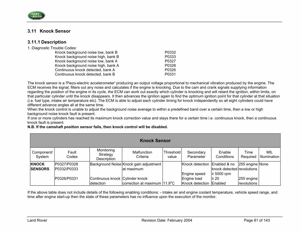
Land Rover Revision Date: February 2004 Page 81 of 143
3.11 Knock Sensor
3.11.1 Description 1. Diagnostic Trouble Codes:
Knock background noise low, bank B P0332 Knock background noise high, bank B P0333 Knock background noise low, bank A P0327 Knock background noise high, bank A P0328 Continuous knock detected, bank A P0326 Continuous knock detected, bank B P0331
The knock sensor is a 'Piezo-electric accelerometer' producing an output voltage proportional to mechanical vibration produced by the engine. The ECM receives the signal, filters out any noise and calculates if the engine is knocking. Due to the cam and crank signals supplying information regarding the position of the engine in its cycle, the ECM can work out exactly which cylinder is knocking and will retard the ignition, within limits, on that particular cylinder until the knock disappears. It then advances the ignition again to find the optimum ignition point for that cylinder at that situation (i.e. fuel type, intake air temperature etc). The ECM is able to adjust each cylinder timing for knock independently so all eight cylinders could have different advance angles all at the same time. When the knock control is unable to adjust the background noise average to within a predefined band over a certain time, then a low or high background noise knock fault is present. If one or more cylinders has reached its maximum knock correction value and stays there for a certain time i.e. continuous knock, then a continuous knock fault is present. N.B. If the camshaft position sensor fails, then knock control will be disabled.
Knock Sensor
Component/ System
Fault Codes
Monitoring Strategy
Description
Malfunction Criteria
Threshold value
Secondary Parameter
Enable Conditions
Time Required
MIL Illumination
KNOCK P0327/P0328 Background Noise Knock gain adjustment Knock detection Enabled & no 255 engine None SENSORS P0332/P0333 at maximum knock detected revolutions Engine speed ≥ 5000 rpm P0326/P0331 Continuous knock Cylinder knock Engine load ≥ 20 255 engine detection correction at maximum 11.9oC Knock detection Enabled revolutions
If the above table does not include details of the following enabling conditions: - intake air and engine coolant temperature, vehicle speed range, and time after engine start-up then the state of these parameters has no influence upon the execution of the monitor.
Land Rover Revision Date: February 2004 Page 82 of 143
3.12 Throttle Position Sensor
3.12.1 Description 1. Diagnostic Trouble Codes:
Throttle Position Sensor - Low out of range P0122 Throttle Position Sensor - High out of range P0123 Throttle Position Sensor - Signal error fault P0121
2. Monitoring Procedure Summary. Problems with the throttle potentiometer will be detected using a range test. If this test is not passed then the appropriate fault counter will be incremented, otherwise it will be decremented. If the count reaches a given threshold then a fault is present. Range check. A voltage being read from the sensor will be compared to upper and lower limits TPOT DIAG MAX VOLTAGE and TPOT DIAG MIN VOLTAGE. If the voltage is outside these limits then a fault counter will be incremented, if not then the counter will be decremented until zero. If the value of the fault counter reaches the limit value TPOT DIAG FAULT LIMIT then a range fault is present, the fault will remain present until the counter reaches zero. The test for maximum voltage will not be performed at high engine loads as full throttle can cause the maximum voltage to be read. The load threshold below which this test can be performed is TPOT DIAG MAX TEST LOAD. Also the fault counter will not be incremented until all of the required conditions for maximum voltage test to fail have been present for greater than a time TPOT DIAG RANGE DELAY. Signal Error Fault The system calculates a value for the current air mass flow rate through the engine based on the throttle signal, engine rpm, intake air temperature and ISC valve position. This estimate is compared to the real measured air mass flow rate. If the difference between the two values is greater than a given percentage, then a fault counter is incremented. If the difference is less, then the fault counter is decremented. A different percentage limit is applied in each direction (estimate > actual and actual > estimate). 3. Primary Detection Parameter Throttle voltage - measured in volts, the output of an Analogue to Digital converter circuit. 4. Fault Criteria Limits Throttle Position Sensor - Low out of range 40mV Throttle Position Sensor - High out of range 4V Throttle Signal Error (Lower than actual) 300 % Throttle Signal Error (Higher than actual) 450 %
Land Rover Revision Date: February 2004 Page 83 of 143
5. Monitoring Conditions The low range check will take place whenever there is power to the ECM; the high range check will take place when the engine speed and load is above and below a prescribed threshold respectively; and the system is in a steady state condition. The signal error check is performed at steady state conditions when both engine speed and engine load are above respective thresholds.
TPOT DIAG MAX TEST LOAD, defined in units of air per stroke: 16% TPOT DIAG RANGE DELAY allows engine load to rise after snap opening of the throttle: 2 seconds TPOT DIAG FAULT LIMIT, required number of fault events to flag a fault: 40 TPOT DIAG XCHK SPEED THRESH, used in signal error check: 600rpm TPOT DIAG XCHK LOAD THRESH, used in signal error check: 19.9 %
6. Monitoring Time Length / Frequency of Checks The frequency if the throttle potentiometer diagnostic is 40Hz. 7. Criteria for Storing Fault Code Two successive trips where the throttle potentiometer monitoring system indicates a failed potentiometer. 8. Criteria for Illuminating MIL Two successive trips where the throttle potentiometer monitoring system indicates a failed potentiometer. 9. Criteria for Determining Out of Range Input Signals The throttle potentiometer is subject to a minimum and maximum voltage limit of 40mV and 4.0V respectively.
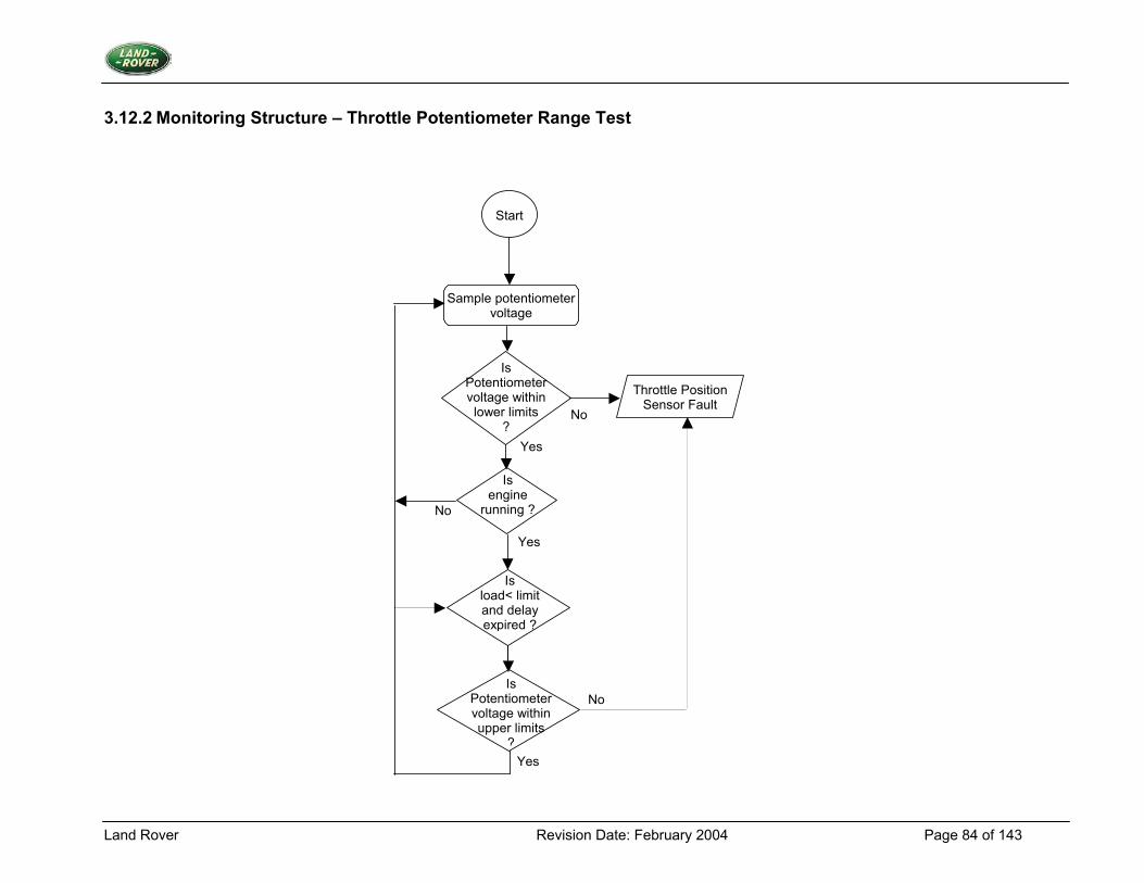
Land Rover Revision Date: February 2004 Page 84 of 143
3.12.2 Monitoring Structure – Throttle Potentiometer Range Test
Start
Sample potentiometer voltage
Is Potentiometer voltage within lower limits
?
Is engine
running ?No
Throttle Position Sensor Fault
Yes
Yes
No
Is Potentiometer voltage within upper limits
?Yes
No
Is load< limit and delay expired ?
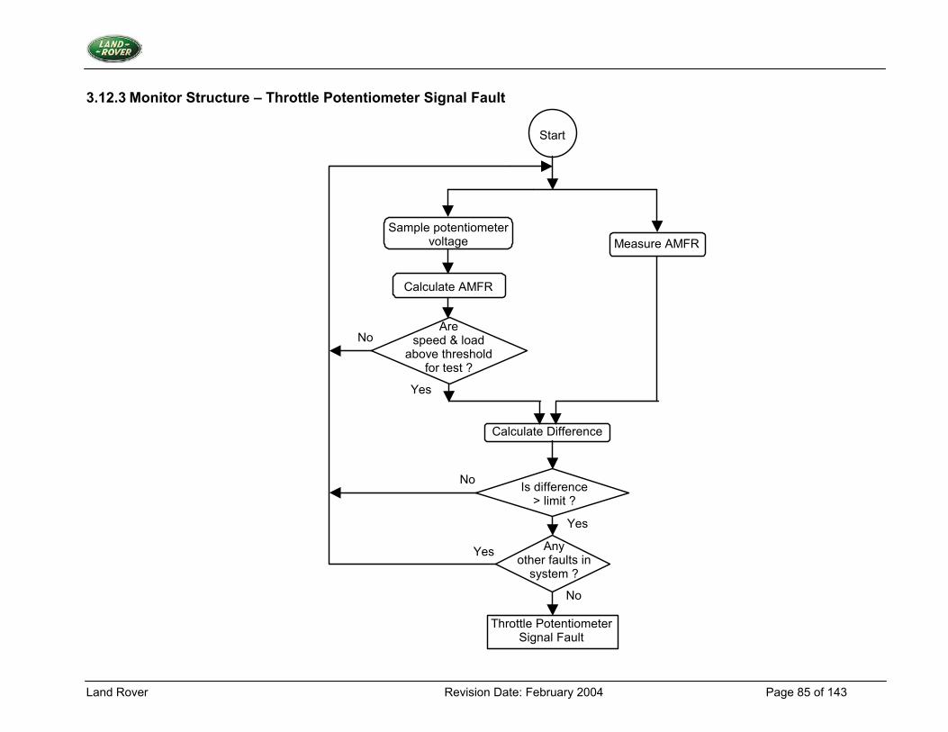
Land Rover Revision Date: February 2004 Page 85 of 143
3.12.3 Monitor Structure – Throttle Potentiometer Signal Fault
Sample potentiometer voltage
Calculate AMFR
Measure AMFR
Are speed & load
above threshold for test ?
Yes
Calculate Difference
Is difference > limit ?
No
Throttle Potentiometer Signal Fault
Any other faults in
system ?
Yes
Yes
No
No
Start
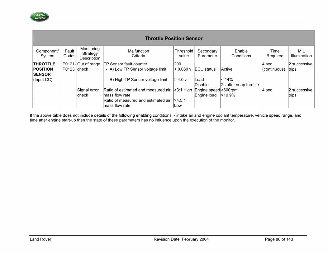
Land Rover Revision Date: February 2004 Page 86 of 143
Throttle Position Sensor
Component/ System
Fault Codes
Monitoring Strategy
Description
Malfunction Criteria
Threshold value
Secondary Parameter
Enable Conditions
Time Required
MIL Illumination
THROTTLE P0121- Out of range TP Sensor fault counter 200 4 sec 2 successive POSITION P0123 check - A) Low TP Sensor voltage limit < 0.060 v ECU status Active (continuous) trips SENSOR (Input CC) - B) High TP Sensor voltage limit > 4.0 v Load < 14% Disable 2s after snap throttle Signal error Ratio of estimated and measured air >3:1 High Engine speed >600rpm 4 sec 2 successive check mass flow rate Engine load >19.9% trips Ratio of measured and estimated air >4.5:1 mass flow rate Low
If the above table does not include details of the following enabling conditions: - intake air and engine coolant temperature, vehicle speed range, and time after engine start-up then the state of these parameters has no influence upon the execution of the monitor.
Land Rover Revision Date: February 2004 Page 87 of 143
3.13 Engine Control Module Self Test
3.13.1 Description 1. Diagnostic Trouble Code:
ECM Self Check Fault P0605 2. Monitoring Procedure The ECM uses EEPROM to store long term adapted values, tune set-up values, DTC's and freeze frame data etc. If the EEPROM becomes corrupted then the system cannot perform as designed. The ECM will then revert to default data to allow the vehicle to continue running. The EEPROM also stores a set of data, which holds the EEPROM_Calibration_Data. This data is used to determine whether the EEPROM has become corrupted. It is assumed that if this data is corrupt then the adaptive and tune data etc will also be corrupt. The ECM attempts to restore data from two separate sets of locations in the EEPROM. Each set of locations holds a copy of the entire set of data to be stored in EEPROM. The ECM checks each piece of data it restores using a Cyclic Redundancy Check (CRC). If this check fails then the ECM will try to retrieve the copy of that piece of data from the alternative memory location. This data is also subjected to a cyclic redundancy check. If the second check fails then the system will use a default for this piece of data and copy it to both sets of locations. If both sets of EEPROM_Calibration_Data Cyclic Redundancy Checks fail, then the system will recognise that there is an internal ECM fault present. 3. Primary Detection Parameter The test uses stored digital data from several memory locations. 4. Fault Criteria Limits Both sets of EEPROM_Calibration_Data retrieved from the EEPROM must fail the cyclic redundancy check. 5. Monitoring Conditions The ECM always performs this test. 6. Monitoring Time Length / Frequency of Checks The ECM performs the test immediately after power is restored from a dormant state. The test takes no more than 3 seconds to complete. 7. Criteria for Storing a Diagnostic Trouble Code A diagnostic trouble code will be stored immediately if the ECM cannot retrieve valid data from the EEPROM. 8. Criteria for Illuminating MIL The MIL will be illuminated immediately if the ECM cannot retrieve valid data from the EEPROM.
Land Rover Revision Date: February 2004 Page 88 of 143
9. Criteria for Determining Out of Range Input Signals The data is subjected to a cyclic redundancy check.
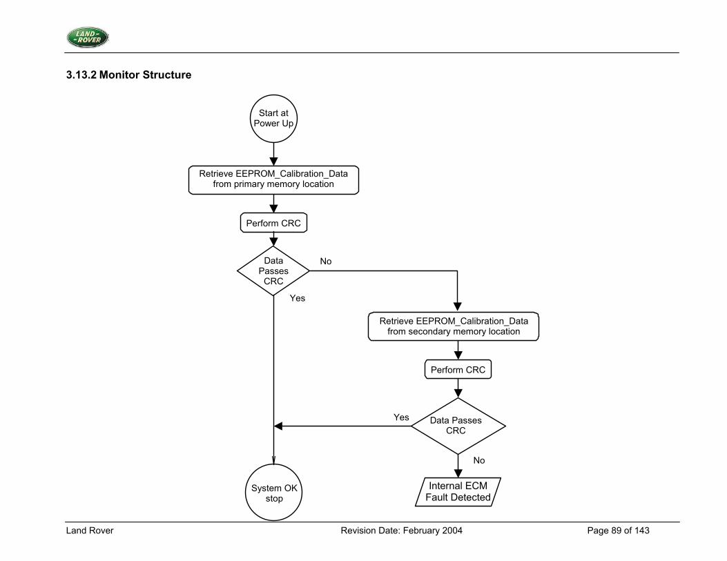
Land Rover Revision Date: February 2004 Page 89 of 143
3.13.2 Monitor Structure
Start at
Power Up
Retrieve EEPROM_Calibration_Data from primary memory location
Data Passes
CRC
Perform CRC
System OK stop
Retrieve EEPROM_Calibration_Data from secondary memory location
Perform CRC
Data Passes CRC
Yes
No
Yes
No
Internal ECM Fault Detected
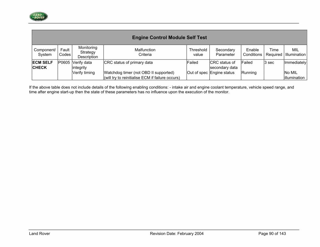
Land Rover Revision Date: February 2004 Page 90 of 143
Engine Control Module Self Test
Component/ System
Fault Codes
Monitoring Strategy
Description
Malfunction Criteria
Threshold value
Secondary Parameter
Enable Conditions
Time Required
MIL Illumination
ECM SELF P0605 Verify data CRC status of primary data Failed CRC status of Failed 3 sec Immediately CHECK integrity secondary data Verify timing Watchdog timer (not OBD II supported) Out of spec Engine status Running No MIL (will try to reinitialise ECM if failure occurs) illumination
If the above table does not include details of the following enabling conditions: - intake air and engine coolant temperature, vehicle speed range, and time after engine start-up then the state of these parameters has no influence upon the execution of the monitor.
Land Rover Revision Date: February 2004 Page 91 of 143
3.14 Fuel Level Sensor
3.14.1 Description 1. Diagnostic Trouble Codes:
Fuel level sensor fault: P0460 (P1199 for pre 1997MY vehicles) Fuel level rationality fault: P0461
2. Monitoring Procedure Range Check The resistance of the fuel level sensor changes in relation to the level of fuel in the tank. Through connection to the input resistor networks of the ECM; any disconnection of the sensor at different points in the harness can generate both high and low input voltages, which are outside the normal operating voltage range. These are detected to diagnose a fuel level fault in the system. If the value of FUEL LEVEL VOLTS is less than FUEL LEVEL DIAG MIN VOLTS or more than FUEL LEVEL DIAG MAX VOLTS, then an appropriate fault counter is incremented up to a limit of FUEL LEVEL DIAGNOSTIC FAULT LIMIT. Otherwise the fault counter is decremented down to a limit of zero. If the fault counter reaches the limit then a fuel level sensor fault is present. Rationality Check The rationality test on the fuel tank level sensor consists of monitoring the fuel level sensor output and ensuring that the output value changes during a period of time. This test will check that the sensor float is not stuck or holed. The test can be passed either through fuel slosh or a drop in level due to fuel usage. To ensure that the test can be completed even where the vehicle is being used for successive short journeys, the test parameters are stored at power down and retrieved at the next power up. 3. Primary Detection Parameter Fuel level - Measured in volts, the outcome of a potential divider calculation. 4. Fault Criteria Limits Fuel Level - Low out of range 0.49V Fuel Level - High 4.8V Fuel Level change must be less than 2 litres for a period of time greater than 59 minutes 5. Monitoring Conditions The range test will take place only when the engine is running. The rationality test will take place when the vehicle speed is greater than 50 mph. 6. Monitoring Time Length / Frequency of Checks The frequency of the fuel level diagnostic is 2Hz. 7. Criteria for Storing a Diagnostic Trouble Code Two successive trips where the fuel level diagnostic indicates a failed fuel level sensor.
Land Rover Revision Date: February 2004 Page 92 of 143
8. Criteria for Illuminating MIL Two successive trips where the fuel level diagnostic indicates a failed fuel level sensor. 9. Criteria for Determining Out of Range Input Signals The fuel level sensor is subject to the range test above.
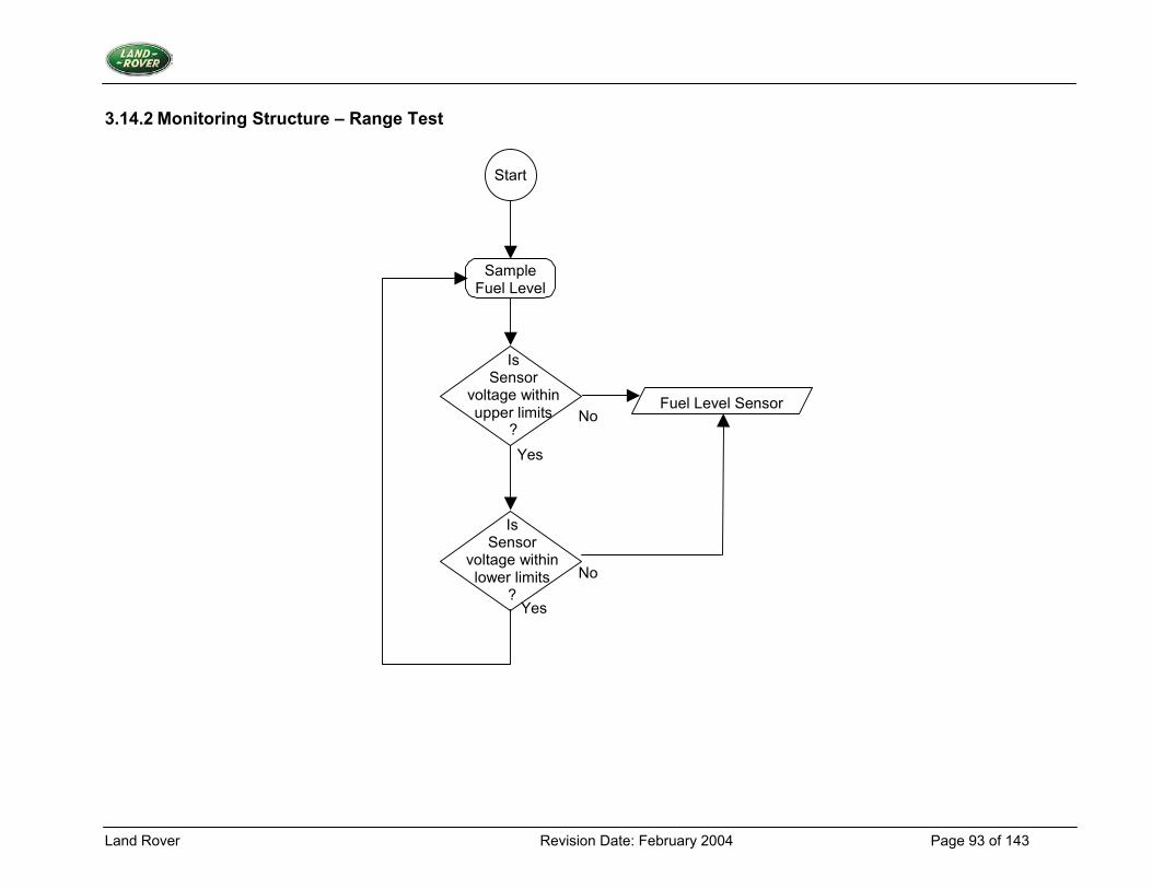
Land Rover Revision Date: February 2004 Page 93 of 143
3.14.2 Monitoring Structure – Range Test
Start
No
No
Yes
Yes
Sample Fuel Level
Is Sensor
voltage within upper limits
?
Is Sensor
voltage within lower limits
?
Fuel Level Sensor
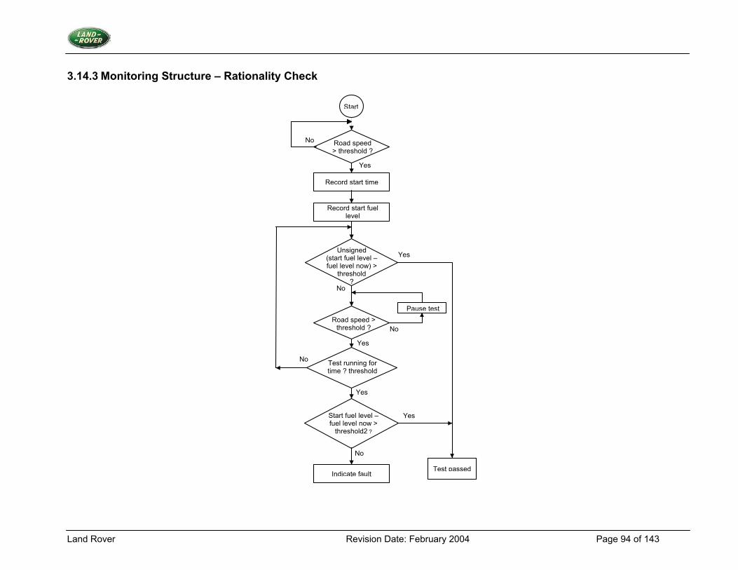
Land Rover Revision Date: February 2004 Page 94 of 143
3.14.3 Monitoring Structure – Rationality Check
Record start time
Road speed > threshold ?
Record start fuel level
Unsigned (start fuel level – fuel level now) >
threshold ?
Test running for time ? threshold
Indicate fault
Start
Start fuel level – fuel level now >
threshold2 ?
Road speed > threshold ?
Test passed
Pause test
Yes
No
Yes
No
Yes
No
Yes
No
No
Yes
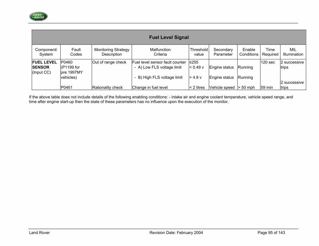
Land Rover Revision Date: February 2004 Page 95 of 143
Fuel Level Signal
Component/ System
Fault Codes
Monitoring Strategy Description
Malfunction Criteria
Thresholdvalue
Secondary Parameter
Enable Conditions
Time Required
MIL Illumination
FUEL LEVEL P0460 Out of range check Fuel level sensor fault counter ≥255 120 sec 2 successive SENSOR (P1199 for - A) Low FLS voltage limit < 0.49 v Engine status Running trips (Input CC) pre 1997MY vehicles) - B) High FLS voltage limit > 4.8 v Engine status Running 2 successive P0461 Rationality check Change in fuel level < 2 litres Vehicle speed > 50 mph 59 min trips
If the above table does not include details of the following enabling conditions: - intake air and engine coolant temperature, vehicle speed range, and time after engine start-up then the state of these parameters has no influence upon the execution of the monitor.

Land Rover Revision Date: February 2004 Page 96 of 143
3.15 Vehicle Speed Sensor
3.15.1 Description 1. Diagnostic Trouble Code:
Vehicle Speed Sensor Malfunction P0500 2. Monitoring Procedure Summary Problems with the vehicle speed sensor will be detected using a number of tests. An engine load test will check for a sustained high engine load being present within a given range of engine speeds and a low road speed. A check is performed using the gearbox retard request signal from the electronic automatic gearbox. If these requests are being received with a low road speed then the test will fail Engine Load Test If the engine load is above a constant, RS DIAG LOAD THRESHOLD for a time greater than RS DIAG LOAD TIME with the engine speed above RS DIAG ENGINE SPEED MIN and RS DIAG LOW ROAD SPEED is true then a fault counter (RS DIAG LOAD FAULTS) will be incremented. Should the test be passed then the fault counter will be decremented to until zero. If the value of the fault counter reaches the limit value RS DIAG FAULT LIMIT then a road speed fault is present. Gear Change Request Check On electronic automatic vehicles a signal is sent from the automatic transmission control module to request an ignition retard to smooth out gear changes. This signal, GEAR CHANGE REQUEST, will be monitored and if it occurs when RS DIAG LOW ROAD SPEED is true then a fault count RS DIAG GEAR FAULTS will be incremented. On each ignition retard request when RS DIAG LOW ROAD SPEED is false and also on each transition of the neutral/drive switch state NDSWITCH OUTPUT the fault counter is decremented. If the value of the fault counter reaches the limit value RS DIAG GEAR FAULT LIMIT then a gear change fault is present until the counter reaches zero. 3. Primary Detection Parameter Road Speed - Road speed sensor edges indicating > 1 mph. Presence of 30 gear change requests during low road speed conditions. 4. Fault Criteria Limits Presence or not of road speed sensor edges 5. Monitoring Conditions The check for road speed will occur under conditions where engine load and speed suggest that the engine is working against genuine road loads (not ancillary loads). RS DIAG LOAD THRESHOLD - 80% load RS DIAG LOAD TIME, a time period ensuring that load is constant, 5 seconds. RS DIAG ENGINE SPEED MIN, 2500 rpm RS DIAG FAULT LIMIT 40 events
Land Rover Revision Date: February 2004 Page 97 of 143
The check for a gear change request signal from the automatic transmission control module is performed whenever there is a low vehicle speed indicated from the vehicle speed sensor. 6. Monitoring Time Length / Frequency of Checks The vehicle speed sensor diagnostic operates at a frequency of 10Hz. 7. Criteria for Storing a Diagnostic Trouble Code Two successive trips where the vehicle speed diagnostic indicates a failed vehicle speed sensor. 8. Criteria for Illuminating MIL Two successive trips where the vehicle speed diagnostic indicates a failed vehicle speed sensor. 9. Criteria for Determining Sensor Functionality The vehicle speed sensor produces a non-linear output; the criteria will be signal/no signal.
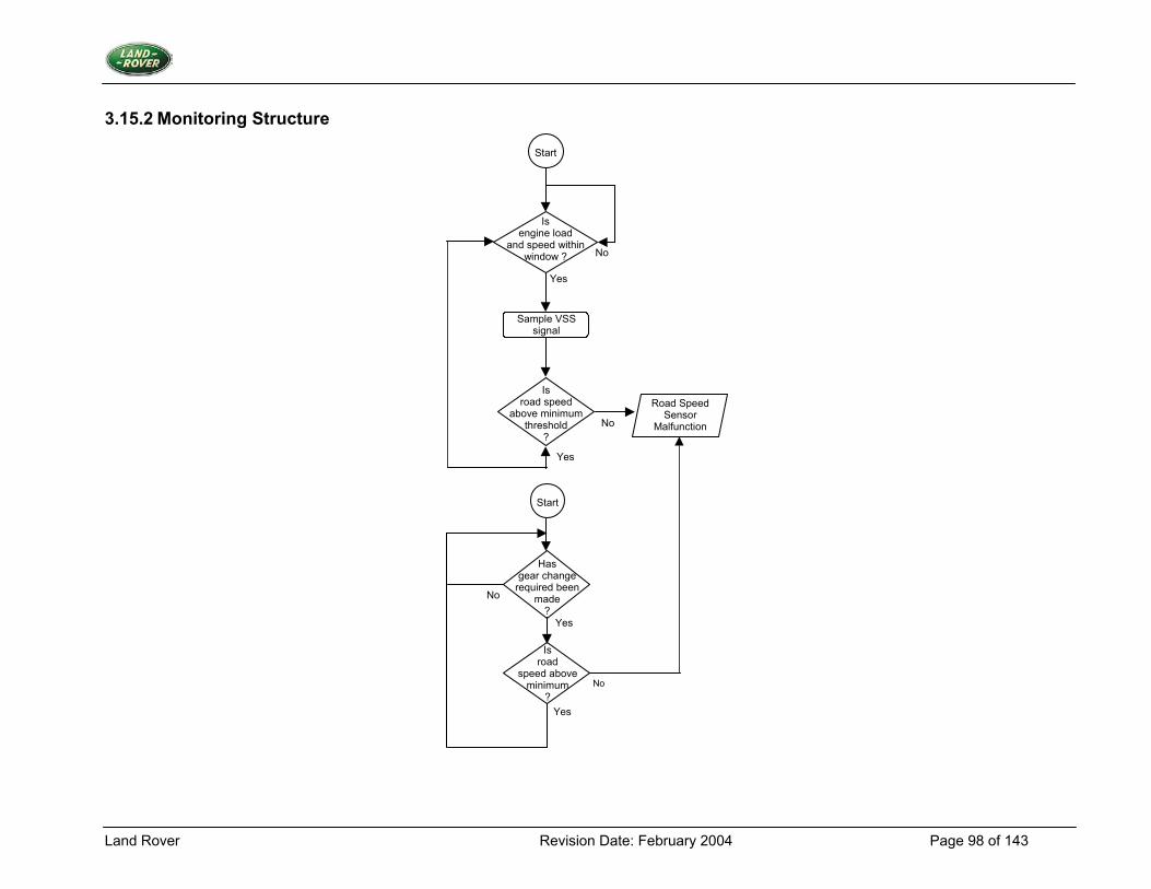
Land Rover Revision Date: February 2004 Page 98 of 143
3.15.2 Monitoring Structure
Start
Yes
No
Is engine load
and speed within window ?
Sample VSS signal
Is road speed
above minimum threshold
?
Road Speed Sensor
Malfunction
No
Yes
Yes
No
No
Is road
speed above minimum
?
Has gear change
required been made
?
Start
Yes
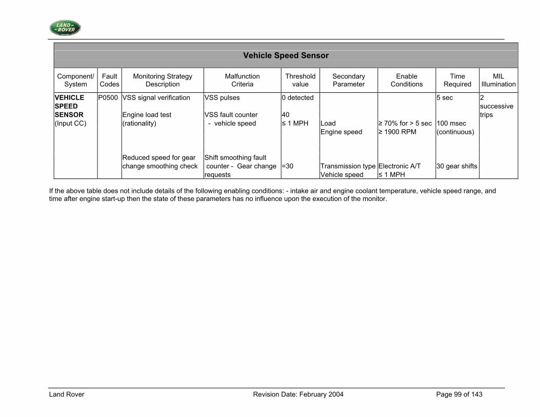
Land Rover Revision Date: February 2004 Page 99 of 143
Vehicle Speed Sensor
Component/ System
Fault Codes
Monitoring Strategy Description
Malfunction Criteria
Threshold value
Secondary Parameter
Enable Conditions
Time Required
MIL Illumination
VEHICLE P0500 VSS signal verification VSS pulses 0 detected 5 sec 2 SPEED successive SENSOR Engine load test VSS fault counter 40 trips (Input CC) (rationality) - vehicle speed ≤ 1 MPH Load ≥ 70% for > 5 sec 100 msec Engine speed ≥ 1900 RPM (continuous) Reduced speed for gear Shift smoothing fault change smoothing check counter - Gear change =30 Transmission type Electronic A/T 30 gear shifts requests Vehicle speed ≤ 1 MPH
If the above table does not include details of the following enabling conditions: - intake air and engine coolant temperature, vehicle speed range, and time after engine start-up then the state of these parameters has no influence upon the execution of the monitor.
Land Rover Revision Date: February 2004 Page 100 of 143
3.16 Power Supplies
3.16.1 Description 1. Diagnostic Trouble Code:
System Voltage Malfunction P0560 System Voltage Low P0562 System Voltage High P0563
2. Monitoring Procedure Two measurements of battery voltage are made, one coarse resolution and one fine resolution. The coarse resolution signal is subjected to out of range limits; whilst the fine resolution signal has a rationality check performed which ensures that the measured battery voltage is reasonably high when the engine speed is high. This ensures that the alternator is charging correctly. 3. Primary Detection Parameter The two battery voltage measurements both come from an ADC input. The battery voltage is scaled down using a different potential divider in each case to provide the two measurements. Battery Voltage - Fine resolution = 0 to 16 V
Coarse resolution = 0 to 32 V 4. Fault Criteria Limits Out of range limits: Low voltage: 3V High voltage: 29V Rationality check 10.5V 5. Monitoring Conditions The range test is conducted at all times. The rationality check is carried out when engine speed > 1600rpm 6. Monitoring Time Length / Frequency of Checks The tests are performed continuously. 7. Criteria for Storing a Diagnostic Trouble Code Two successive trips where the battery voltage diagnostic indicates a fault. 8. Criteria for Illuminating MIL Two successive trips where the battery voltage diagnostic indicates a fault. 9. Criteria for Determining Out of Range Input Signals The engine speed signal is subject to its own diagnostic strategy.
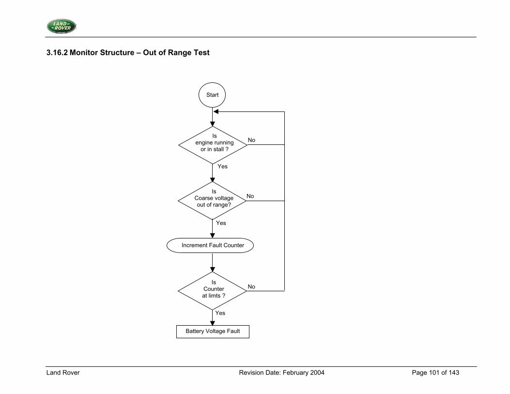
Land Rover Revision Date: February 2004 Page 101 of 143
3.16.2 Monitor Structure – Out of Range Test
Start
Is engine running
or in stall ?
Is Coarse voltage out of range?
Increment Fault Counter
Is Counter at limts ?
Battery Voltage Fault
No
No
No
Yes
Yes
Yes
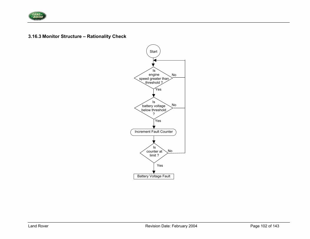
Land Rover Revision Date: February 2004 Page 102 of 143
3.16.3 Monitor Structure – Rationality Check
Start
No
No
Yes
Increment Fault Counter
No
Battery Voltage Fault
Yes
Is engine
speed greater than threshold ?
Is battery voltage below threshold
?
Yes
Is counter at
limit ?
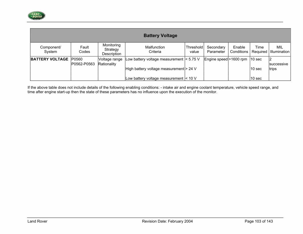
Land Rover Revision Date: February 2004 Page 103 of 143
Battery Voltage
Component/ System
Fault Codes
Monitoring Strategy
Description
Malfunction Criteria
Thresholdvalue
Secondary Parameter
Enable Conditions
Time Required
MIL Illumination
BATTERY VOLTAGE P0560 Voltage range Low battery voltage measurement < 5.75 V Engine speed >1600 rpm 10 sec 2 P0562-P0563 Rationality successive High battery voltage measurement > 24 V 10 sec trips Low battery voltage measurement < 10 V 10 sec
If the above table does not include details of the following enabling conditions: - intake air and engine coolant temperature, vehicle speed range, and time after engine start-up then the state of these parameters has no influence upon the execution of the monitor.
Land Rover Revision Date: February 2004 Page 104 of 143
3.17 Fuel Tank Temperature Sensor
3.17.1 Description 1. Diagnostic Trouble Codes:
Fuel Tank Temperature Sensor Circuit High Input P0183 Fuel Tank Temperature Sensor Circuit Low Input P0182 Fuel Tank Temperature Sensor Rationality Check P0181
2. Monitoring Procedure Range Check Problems with the fuel tank temperature (FTT) sensor are detected using a range test. The range test tests for input values outside expected limits. If this test is not passed then the appropriate fault counter will be incremented, otherwise it will be decremented. If the counter reaches a given threshold then a fault is present. While fault counting is in progress a back-up value of fuel tank temperature will be supplied to avoid the problems of incorrect values reaching the rest of the system. Rationality Check The test on the fuel tank temperature sensor comprises of comparing the output from the sensor with a tolerance band based around the value of engine coolant temperature. A fuel tank temperature test will check that the sensor does not have an altered resistance characteristic or the sensor has not fallen off. 3. Primary Detection Parameter Fuel Tank Temperature - measured as thermistor voltage. 4. Fault Criteria Limits Fuel Tank Temperature – Low voltage (out of range) < 0.0585 V (i.e. > 145 0C) Fuel Tank Temperature – High voltage (out of range) > 4.895 V (i.e. < -45 0C) Error between fuel tank temperature and engine coolant temperature > 20 0C or < -120 0C 5. Monitoring Conditions The range check will take place whenever there is power to the ECM. The rationality check will take place once the engine has been running for a time > 40 seconds. 6. Monitoring Time Length / Frequency of Checks The frequency of the fuel tank temperature diagnostic is 2Hz. 7. Criteria for Storing a Diagnostic Trouble Code Two successive trips where the fuel tank temperature diagnostic indicates a failed fuel tank temperature sensor. 8. Criteria for Illuminating MIL Two successive trips where the fuel tank temperature diagnostic indicates a failed fuel tank temperature sensor.
Land Rover Revision Date: February 2004 Page 105 of 143
9. Criteria for Determining Out of Range Input Signals The fuel tank temperature thermistor is subject to range testing as above.
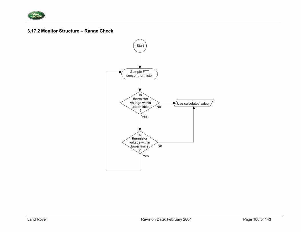
Land Rover Revision Date: February 2004 Page 106 of 143
3.17.2 Monitor Structure – Range Check
Start
Sample FTT sensor thermistor
Is thermistor
voltage within upper limits
? No
No
Yes
Yes
Use calculated value
Is thermistor
voltage within lower limits
?
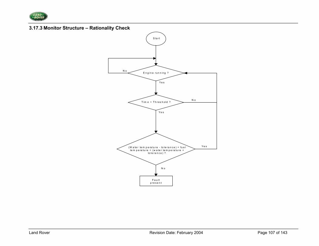
Land Rover Revision Date: February 2004 Page 107 of 143
3.17.3 Monitor Structure – Rationality Check
E n g in e run n ing ?
T im e = T h res h o ld ?
(W a te r te m p e ra tu re - to le ra n c e ) < fu e l te m p e ra tu re < (w a te r te m p e ra tu re +
to le ra n c e ) ?
F a u l t p re s e n t
S ta r t
N o
Y e s
Y e s
N o
Y e s
N o
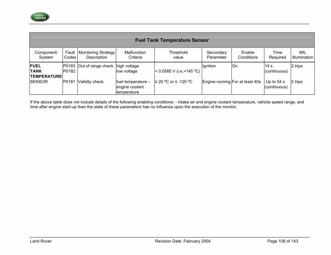
Land Rover Revision Date: February 2004 Page 108 of 143
FUEL P0183 Out of range check high voltage Ignition On 14 s 2 trips TANK P0182 low voltage < 0.0585 V (i.e.>145 ºC) (continuous) TEMPERATURE SENSOR P0181 Validity check fuel temperature – ≥ 20 ºC or ≤ -120 ºC Engine running For at least 40s Up to 54 s 2 trips engine coolant (continuous) temperature If the above table does not include details of the following enabling conditions: - intake air and engine coolant temperature, vehicle speed range, and time after engine start-up then the state of these parameters has no influence upon the execution of the monitor.
Fuel Tank Temperature Sensor
Component/ System
Fault Codes
Monitoring StrategyDescription
Malfunction Criteria
Threshold value
Secondary Parameter
Enable Conditions
Time Required
MIL Illumination
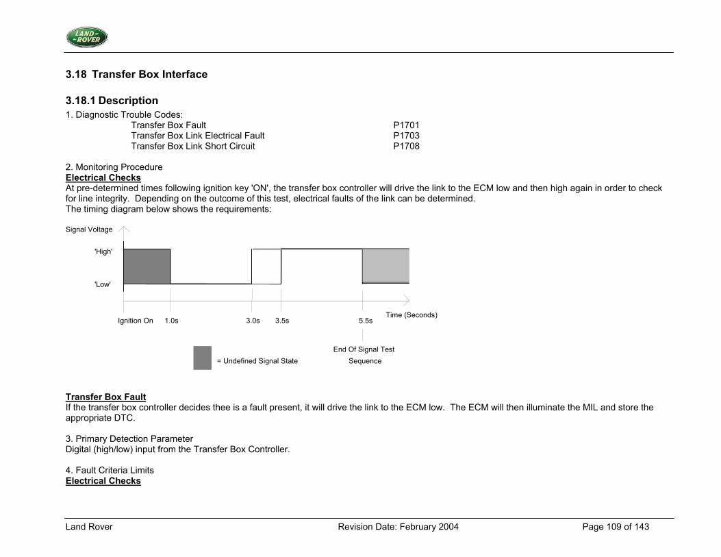
Land Rover Revision Date: February 2004 Page 109 of 143
3.18 Transfer Box Interface
3.18.1 Description 1. Diagnostic Trouble Codes:
Transfer Box Fault P1701 Transfer Box Link Electrical Fault P1703 Transfer Box Link Short Circuit P1708
2. Monitoring Procedure Electrical Checks At pre-determined times following ignition key 'ON', the transfer box controller will drive the link to the ECM low and then high again in order to check for line integrity. Depending on the outcome of this test, electrical faults of the link can be determined. The timing diagram below shows the requirements:
1.0s Ignition On 3.0s 5.5s3.5s
= Undefined Signal State
'High'
'Low'
End Of Signal TestSequence
Time (Seconds)
Signal Voltage
Transfer Box Fault If the transfer box controller decides thee is a fault present, it will drive the link to the ECM low. The ECM will then illuminate the MIL and store the appropriate DTC. 3. Primary Detection Parameter Digital (high/low) input from the Transfer Box Controller. 4. Fault Criteria Limits Electrical Checks
Land Rover Revision Date: February 2004 Page 110 of 143
The link must be driven low within 1.0s of ignition key 'ON' and then high again within a further 2.5s. The link must stay high for at least 2.0s. (See the timing diagram above.) Transfer Box Fault The transfer box controller must drive the link low for at least 2 seconds before fault is stored. 5. Monitoring Conditions The electrical checks are done after every ignition key 'ON'. The electrical checks will be aborted if the battery voltage drops below 8V. The system monitors constantly for a Transfer Box fault, provided there are no electrical faults. 6. Monitoring Time Length / Frequency of Checks The electrical check takes 5.5 seconds and is carried out once after ignition key 'ON' Whilst looking for a Transfer Box Fault, the link is monitored at a 10Hz-sampling rate for the rest of the ignition 'ON' cycle. 7. Criteria for Storing a Diagnostic Trouble Code A DTC will be stored immediately after detecting a fault. 8. Criteria for Illuminating MIL The MIL will be illuminated immediately after detecting a fault. 9. Criteria for Determining Out of Range Input Signals Electrical checks are performed as described above.
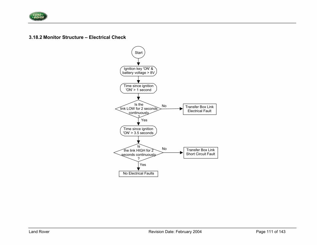
Land Rover Revision Date: February 2004 Page 111 of 143
3.18.2 Monitor Structure – Electrical Check
Yes
Transfer Box Link Electrical Fault
Transfer Box Link Short Circuit Fault
Time since ignition 'ON' > 1 second
Is the link LOW for 2 seconds
continuously ?
Time since ignition 'ON' > 3.5 seconds
Is the link HIGH for 2
seconds continuously ?
No Electrical Faults
No
Yes
No
Ignition key 'ON' & battery voltage > 8V
Start
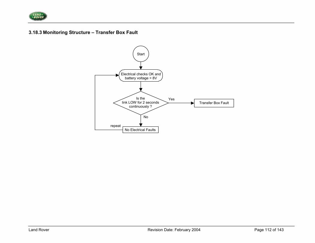
Land Rover Revision Date: February 2004 Page 112 of 143
3.18.3 Monitoring Structure – Transfer Box Fault
Is the link LOW for 2 seconds
continuously ?
No Electrical Faults
Start
Electrical checks OK and battery voltage > 8V
No
YesTransfer Box Fault
repeat
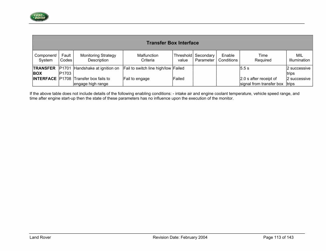
Land Rover Revision Date: February 2004 Page 113 of 143
Transfer Box Interface
Component/ System
Fault Codes
Monitoring Strategy Description
Malfunction Criteria
Threshold value
SecondaryParameter
Enable Conditions
Time Required
MIL Illumination
TRANSFER P1701 Handshake at ignition on Fail to switch line high/low Failed 5.5 s 2 successive BOX P1703 trips INTERFACE P1708 Transfer box fails to Fail to engage Failed 2.0 s after receipt of 2 successive engage high range signal from transfer box trips
If the above table does not include details of the following enabling conditions: - intake air and engine coolant temperature, vehicle speed range, and time after engine start-up then the state of these parameters has no influence upon the execution of the monitor.
Land Rover Revision Date: February 2004 Page 114 of 143
3.19 Park/Neutral Position Switch
3.19.1 Description 1. Diagnostic Trouble Codes:
High Load Neutral/Drive Fault P1514 Gear Change Neutral/Drive Fault P1516 Cranking Neutral/Drive Fault P1517
2. Monitoring Procedure Summary Problems with the Park/Neutral Position (PNP) Switch will be detected using a number of tests. Two tests check whether the switch is incorrectly indicating neutral, by detecting high load conditions or gear changes. A single test checks whether the switch is incorrectly indicating drive, by detecting cranking. If the tests are not passed then the appropriate fault counter will be incremented. If the counter reaches a given threshold then a fault is present. While a fault is present a default value for the Park/Neutral Position Switch will be supplied to the rest of the system. Cranking Test The drive position test will test for engine conditions that indicate that the gearbox is in neutral yet the switch reads drive. The drive position test involves monitoring whether CRANKING mode has been entered. Upon entry to CRANKING mode then a delay of a minimum period of NEUT DRV DIAG CRK INIT DELAY should occur to allow the systems voltages to recover from any start-up transients. The park/neutral position switch is then sampled during the remaining cranking period. The sampling technique is required to avoid the effects of electrical noise during CRANKING. Any switch samples that read drive while CRANKING are fault events. If a greater proportion of samples than NEUT DRV DIAG CRK PERCENT MIN indicate drive, then there is a fault present. Once cranking mode is entered, wait for NEUT DRV DIAG CRK INIT DELAY. As long as the engine is still cranking then start sampling, recording both the total number of samples and the number of those switch samples that were fault events, i.e. switch reads drive. Only stop sampling once the engine stops cranking or the total number of samples is NEUT DRV DIAG CRK SAMPLES MAX. As long as at least a minimum of NEUT DRV DIAG CRK SAMPLES MIN samples have occurred before the end of the cranking period, then continue the test. The proportion of samples that indicate drive will be calculated; if NEUT DRV DIAG CRK PERCENT MIN indicates drive then this indicates the switch is in drive hence there is a fault present.
Land Rover Revision Date: February 2004 Page 115 of 143
Neutral Position Test (i). High Load Test. This test establishes that there is a false indication of neutral from the park/neutral position switch whilst the gearbox is in drive by checking for high engine load whenever high engine speed is seen in neutral. High load indicates that the vehicle is in gear, and low load implies neutral. The test operates as follows:
1. While in neutral, if the engine load exceeds the NEUT_DRV_HIGH_LOAD_THRESH when the engine speed exceeds NEUT_DRV_DIAG_ENGINE_SPD_MIN, then the fault counter is incremented. If the counter reaches NEUT_DRV_DIAG_HIGH_LOAD_FAULT_LIMIT then a fault is recorded.
2. While in neutral, if the engine load is less than or equal to the NEUT_DRV_DIAG_HIGH_LOAD_THRESH when the engine speed still exceeds NEUT_DRV_DIAG_ENGINE_SPD_MIN, then decrement the fault counter.
3. If the park/neutral position switch equals drive, then the fault counter is decremented down to a limit of zero. (ii). Gear Change Test The test involves monitoring for gear change requests while the switch indicates neutral. This can be done by monitoring for ignition alteration due to the presence of the GEAR_CHANGE_IN_PROGRESS flag, which occurs during gear changes. If a gear change request occurs while the park/neutral position switch indicates neutral, then the gear change fault event counter will be incremented. If a gear change request occurs while the neutral drive switch indicates drive, then decrement the gear change fault event counter. If the counter reaches NEUT_DRV_DIAG_GEAR_FAULT _LIMIT then a fault is recorded. 3. Primary Detection Parameter Park/neutral position switch input - an internal state generated from the voltage output of the park/neutral position switch. 4. Fault Criteria Limits High load Test - false indication of neutral from the park/neutral position switch whilst the gearbox is in drive. Cranking Test - Indication from engine conditions that the gearbox is in neutral yet the switch reads drive. Gear Change Test - indication from the GEAR_CHANGE_IN_PROGRESS flag that a gear change is in progress when the park/neutral position switch indicates that the gearbox is in neutral. 5. Monitoring Conditions Cranking Test - The engine status is cranking. NEUT_DRV_DIAG_CRK_INIT_DELAY, used to ensure that the system's voltages is stable, 1.0sec NEUT_DRV_DIAG_CRK _SAMPLES_MAX, maximum number of samples taken to verify switch functionality, 50 NEUT_DRV_DIAG_CRK_SAMP_MIN, minimum number of samples taken to verify switch functionality, 15 NEUT_DRV_DIAG_CRK_PERCENT_MIN, minimum percentage of drive indications from samples taken required to indicate a fault, 90 High Load Test - The engine load must be equal to or below 80% and the engine speed must be equal to or above 1500RPM, the water temperature above 800C and the gearbox does not indicate a fault. Gear Change Test - The gearbox does not indicate a fault and the engine is not in stall.
Land Rover Revision Date: February 2004 Page 116 of 143
6. Monitoring Time Length / Frequency of Checks The frequency of the park/neutral position switch diagnostic is 10Hz. 7. Criteria for Storing a Diagnostic Trouble Code Two successive journeys where the diagnostic indicates a failed park/neutral position switch. 8. Criteria for Illuminating MIL The MIL will not be illuminated. 9. Criteria for Determining Out of Range Input Signals The park/neutral position switch produces a non-linear output; the criteria will be signal/no signal.
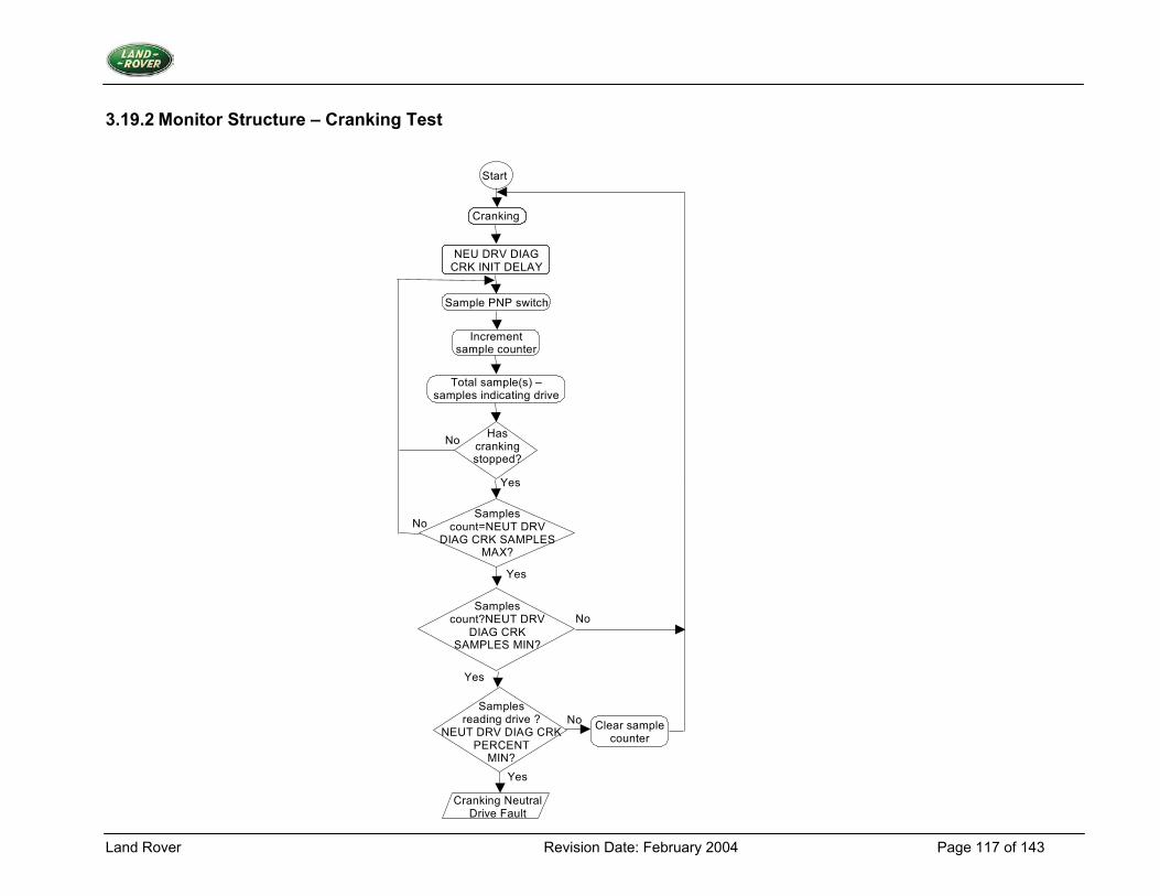
Land Rover Revision Date: February 2004 Page 117 of 143
3.19.2 Monitor Structure – Cranking Test
Start
Sample PNP switch
Increment sample counter
Total sample(s) – samples indicating drive
Samples count=NEUT DRV
DIAG CRK SAMPLES MAX?
Has cranking stopped?
No
Samples reading drive ?
NEUT DRV DIAG CRK PERCENT
MIN?
Clear sample counter
Cranking Neutral Drive Fault
Yes
Yes
Yes
Samples count?NEUT DRV
DIAG CRK SAMPLES MIN?
No
Yes
No
No
Cranking
NEU DRV DIAG CRK INIT DELAY
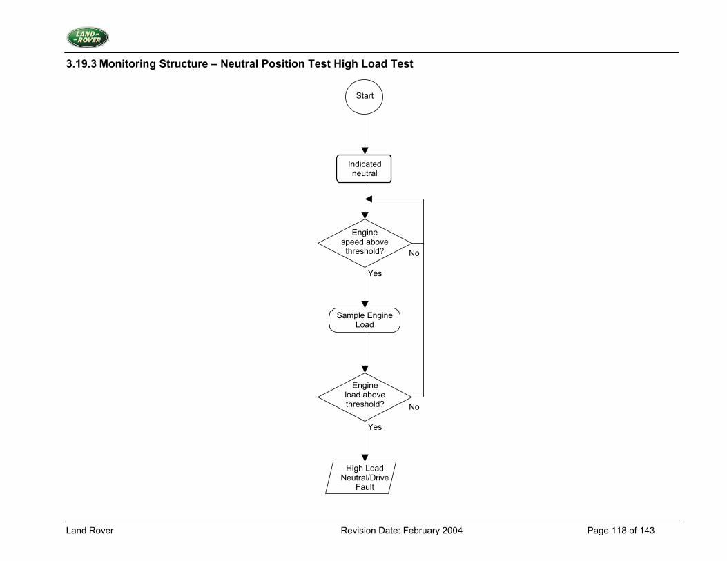
Land Rover Revision Date: February 2004 Page 118 of 143
3.19.3 Monitoring Structure – Neutral Position Test High Load Test
Start
Sample Engine Load
Engine speed above threshold?
Engine load above threshold?
High Load Neutral/Drive
Fault
No
No
Yes
Yes
Indicated neutral
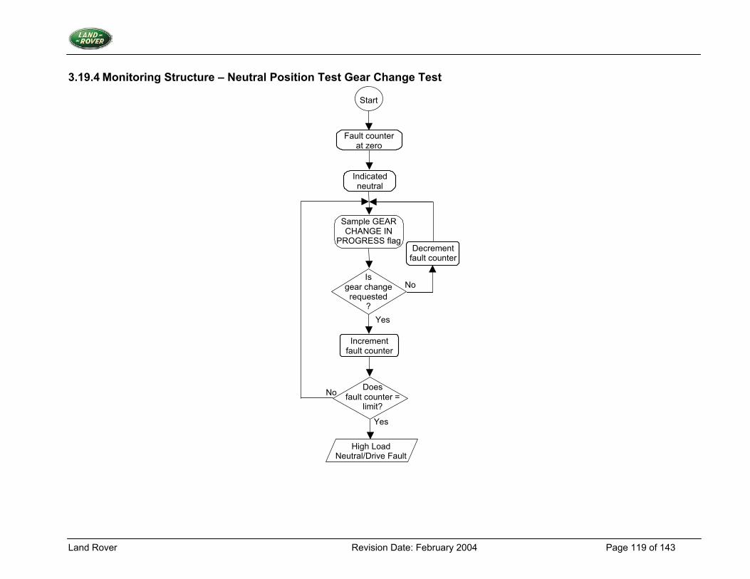
Land Rover Revision Date: February 2004 Page 119 of 143
3.19.4 Monitoring Structure – Neutral Position Test Gear Change Test
Sample GEAR CHANGE IN
PROGRESS flag
Yes
Is gear change requested
?
No
Does fault counter =
limit?
High Load Neutral/Drive Fault
Yes
Start
No
Fault counter at zero
Indicated neutral
Decrement fault counter
Increment fault counter
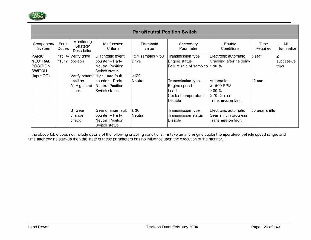
Land Rover Revision Date: February 2004 Page 120 of 143
Park/Neutral Position Switch
Component/ System
Fault Codes
Monitoring Strategy
Description
Malfunction Criteria
Threshold value
Secondary Parameter
Enable Conditions
Time Required
MIL Illumination
PARK/ P1514- Verify drive Diagnostic event 15 ≤ samples ≤ 50 Transmission type Electronic automatic 6 sec 2 NEUTRAL P1517 position counter – Park/ Drive Engine status Cranking after 1s delay successive POSITION Neutral Position Failure rate of samples ≥ 90 % trips SWITCH Switch status (Input CC) Verify neutral High Load fault ≥120 position counter – Park/ Neutral Transmission type Automatic 12 sec A) High load Neutral Position Engine speed ≥ 1500 RPM check Switch status Load ≥ 80 % Coolant temperature ≥ 70 Celsius Disable Transmission fault B) Gear Gear change fault ≥ 30 Transmission type Electronic automatic 30 gear shifts change counter – Park/ Neutral Transmission status Gear shift in progress check Neutral Position Disable Transmission fault Switch status
If the above table does not include details of the following enabling conditions: - intake air and engine coolant temperature, vehicle speed range, and time after engine start-up then the state of these parameters has no influence upon the execution of the monitor.
Land Rover Revision Date: February 2004 Page 121 of 143
3.20 Fuel Injectors
3.20.1 Description 1. Diagnostic Trouble Codes:
Cylinder 1 Injector Circuit Malfunction P0201 Cylinder 2 Injector Circuit Malfunction P0202 Cylinder 3 Injector Circuit Malfunction P0203 Cylinder 4 Injector Circuit Malfunction P0204 Cylinder 5 Injector Circuit Malfunction P0205 Cylinder 6 Injector Circuit Malfunction P0206 Cylinder 7 Injector Circuit Malfunction P0207 Cylinder 8 Injector Circuit Malfunction P0208 Cylinder 1 Injector Circuit open/short to ground P1201 Cylinder 2 Injector Circuit open/short to ground P1202 Cylinder 3 Injector Circuit open/short to ground P1203 Cylinder 4 Injector Circuit open/short to ground P1204 Cylinder 5 Injector Circuit open/short to ground P1205 Cylinder 6 Injector Circuit open/short to ground P1206 Cylinder 7 Injector Circuit open/short to ground P1207 Cylinder 8 Injector Circuit open/short to ground P1208
2. Monitoring Procedure Summary Problems with the injectors are detected using two tests, the first cannot distinguish between open circuit and short to battery or ground faults. The second isolates the short to battery condition. Injector Hardware Test This test determines whether the flag, INJ DIAG INJ BUFF STATUS [1.NCYLS] indicates a fault event while the vehicle status is ENGINE RUNNING. If a fault event has occurred, then increment that injectors' fault counter, INJ DIAG INJ FAULT CNTR [1.NCYLS], up to a limit of INJ DIAG FAULT LIMIT. If INJ DIAG NO FAULT LIMIT consecutive no fault events occur, then that injectors' fault counter is decremented, down to a limit of zero. If the count reaches INJ DIAG FAULT LIMIT then an injector hardware fault is present. Injector Open Circuit or Ground Short Test This test determines whether the flag, INJ DIAG INJ BUFF STATUS [1.NCYLS] indicates a fault event while the engine is in the STALL condition or during ECU POWER DOWN. If a fault event has occurred, then increment that injectors' fault counter, INJ DIAG OC FAULT CNTR [1.NCYLS], up to a limit of INJ DIAG FAULT LIMIT. If INJ DIAG NO FAULT LIMIT consecutive no fault events occur, then decrement that injectors' fault counter, down to a limit of zero. If the count reaches INJ DIAG FAULT LIMIT then an injector open circuit or ground short fault is present.
Land Rover Revision Date: February 2004 Page 122 of 143
3. Primary Detection Parameter Hardware fault status from injector drive ASIC which monitors line voltage before low side drive transistor. 4. Fault Criteria Limits Injector Diagnostic Fault limit = 10; limit used to define that there is a fault present with the injector. Injector Diagnostic/no Fault limit = 40; limit used to define that there is not a fault present with the injector. 5. Monitoring Conditions The injector hardware diagnostic will be run when the vehicle status is engine running. The injector open circuit or ground short test will be run when the engine is in stall or during ECM power down. 6. Monitoring Time Length / Frequency of Checks The injector hardware diagnostic will be run at a frequency of 10Hz whilst the engine is running. The injector open circuit or ground short test will be run whenever the engine is in the stall condition or during ECM power down. 7. Criteria for Storing a Diagnostic Trouble Code Two successive trips where the diagnostic routines indicate a failed injector or injector circuit. 8. Criteria for Illuminating MIL Two successive trips where the diagnostic routines indicate a failed injector or injector circuit. 9. Criteria for Determining Out of Range Input Signals The injector diagnostic sampling technique monitors non-linear signals; the criteria will be signal/no signal.
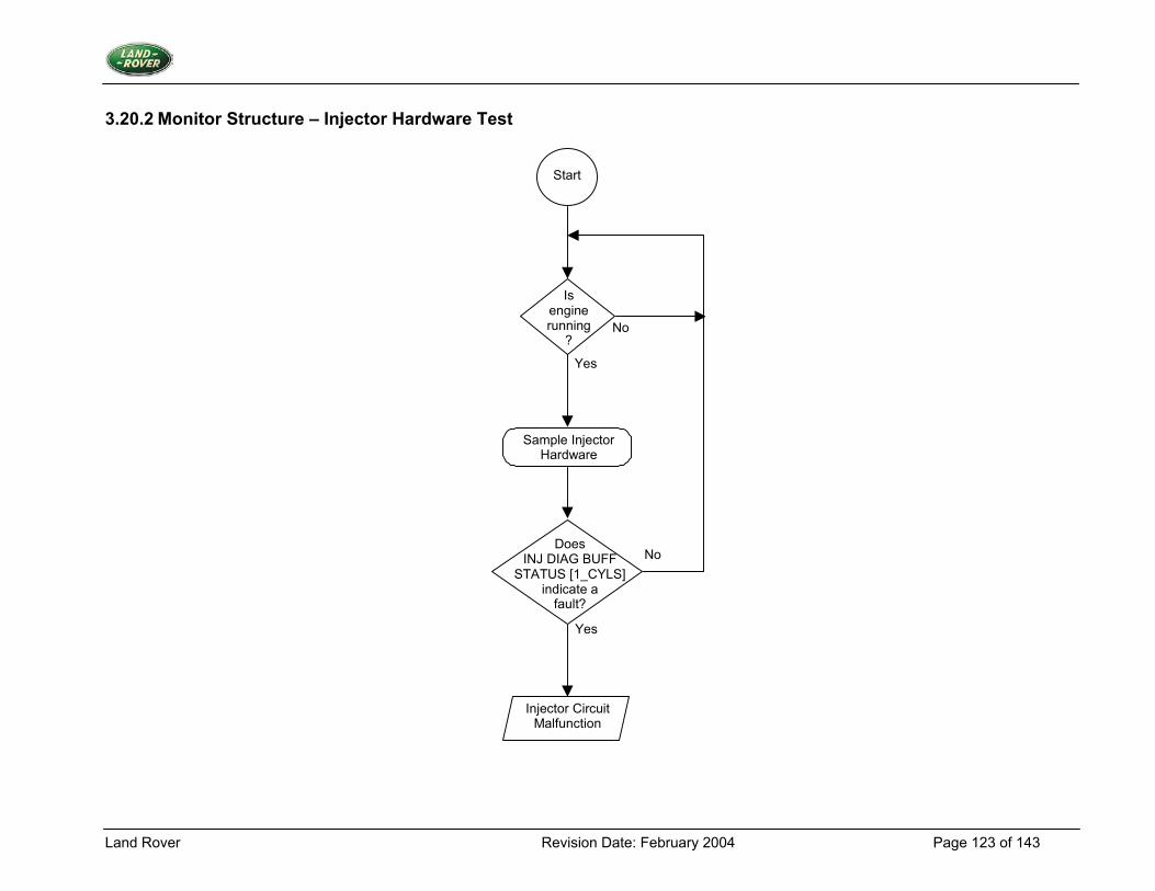
Land Rover Revision Date: February 2004 Page 123 of 143
3.20.2 Monitor Structure – Injector Hardware Test
Start
Is engine running
?
Yes
No
Sample Injector Hardware
Does INJ DIAG BUFF
STATUS [1_CYLS] indicate a
fault?
Yes
No
Injector Circuit Malfunction
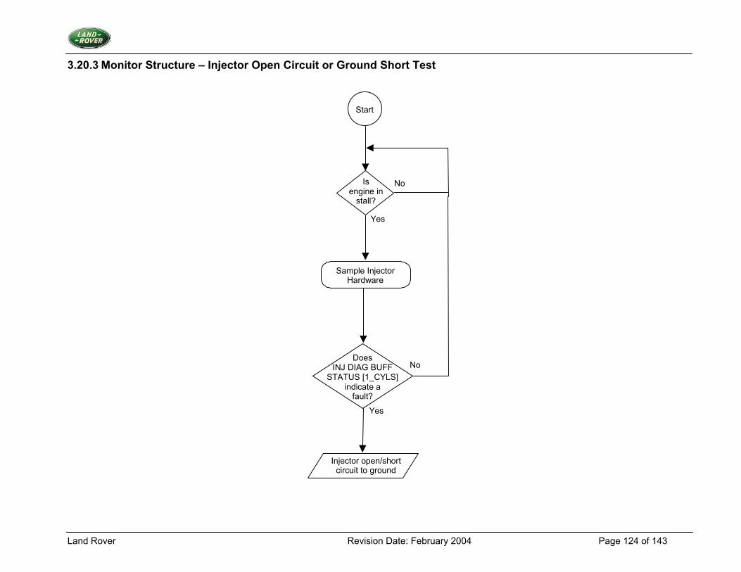
Land Rover Revision Date: February 2004 Page 124 of 143
3.20.3 Monitor Structure – Injector Open Circuit or Ground Short Test
Start
Yes
No
Sample Injector Hardware
Does INJ DIAG BUFF
STATUS [1_CYLS] indicate a
fault?
Yes
No
Is engine in
stall?
Injector open/short circuit to ground
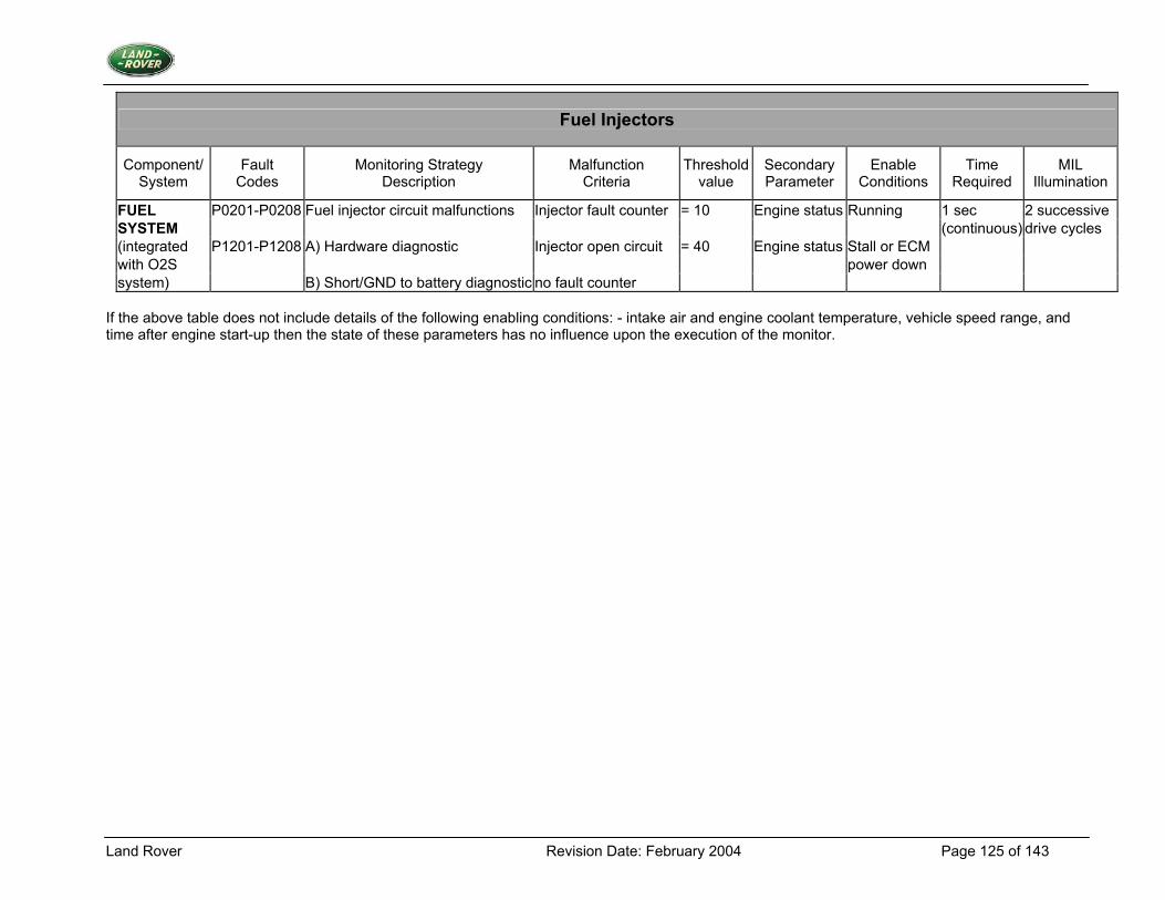
Land Rover Revision Date: February 2004 Page 125 of 143
Fuel Injectors
Component/ System
Fault Codes
Monitoring Strategy Description
Malfunction Criteria
Thresholdvalue
Secondary Parameter
Enable Conditions
Time Required
MIL Illumination
FUEL P0201-P0208 Fuel injector circuit malfunctions Injector fault counter = 10 Engine status Running 1 sec 2 successive SYSTEM (continuous) drive cycles (integrated P1201-P1208 A) Hardware diagnostic Injector open circuit = 40 Engine status Stall or ECM with O2S power down system) B) Short/GND to battery diagnostic no fault counter
If the above table does not include details of the following enabling conditions: - intake air and engine coolant temperature, vehicle speed range, and time after engine start-up then the state of these parameters has no influence upon the execution of the monitor.
Land Rover Revision Date: February 2004 Page 126 of 143
3.21 Idle Speed Control
3.21.1 Description 1. Diagnostic Trouble Codes:
Idle Speed Control System RPM Lower Than Expected P0506 Idle Speed Control System RPM Higher Than Expected P0507 Idle Speed Control System Open Circuit P1508 Idle Speed Control System Short Circuit P1509
2. Monitoring Procedure Summary The open and short circuit tests check for hardware fault events by sampling the stepper motor coils' fault status lines of the Serial Output Devices. The closed loop mode test monitors the cumulative opening and closing idle speed control steps, during closed loop control, a fault event being registered when the cumulative steps applied in either an opening or closing direction exceed threshold values, without causing a corresponding increase or decrease in airflow rate. Closed Loop Test At the start of any closed loop idle speed control, the airflow is sampled, ISC DIAG INIT AIRFLOW, and from that point, the count of the cumulative opening and closing idle speed control steps, ISC CUM STEP SUM CNTR is monitored. No further action is taken until ISC CUM STEP SUM CNTR is greater than ISC DIAG CLOSING STEP THRESH in the closing direction, or is greater than ISC DIAG OPENING STEP THRESH in the opening direction. Then the airflow is sampled again, ISC DIAG FINAL AIRFLOW, and the difference between ISC DIAG FINAL AIRFLOW and ISC DIAG INIT AIRFLOW calculated. If ISC CUM STEP SUM CNTR is greater than ISC DIAG CLOSING STEP THRESH in the closing direction, and the airflow decrease is less than ISC DIAG CLOSING AIRFLOW THRESH, then a closed loop fault event has occurred. If the airflow decreases by more than ISC DIAG CLOSING AIRFLOW THRESH, then the test was passed. If ISC CUM STEP SUM CNTR is greater than ISC DIAG OPENING STEP THRESH in the opening direction, and the airflow increase is less than ISC DIAG OPENING AIRFLOW THRESH, then a closed loop fault event has occurred. If the airflow increases by more than ISC DIAG OPENING AIRFLOW THRESH, then the test was passed. If a fault event has occurred the fault event counter, ISC DIAG CL FAULT CNTR, up to a limit of ISC DIAG CL FAULT LIMIT is incremented. If the test was passed then the closed loop fault event counter is decremented, down to a limit of zero. If the fault event counter reaches ISC DIAG CL FAULT LIMIT then a fault is present. If ISC DIAG CUM STEP CNTR is greater than ISC DIAG OPENING STEP THRESH in the opening direction then an ISC engine speed low fault is present, otherwise an ISC engine speed high fault is present. If the fault event counter equals zero, there are no ISC engine speed low, or high, faults present.
Land Rover Revision Date: February 2004 Page 127 of 143
If ISC STABILITY OCCURRED indicates that the stepper motor adaptive offset has been updated during closed loop control, then re-sample ISC DIAG INIT AIRFLOW, and calculate the airflow difference from this new value. The ISC CUM STEP SUM CNTR will have been reset, so monitor the cumulative step count from this new value. Short Circuit Test The short circuit test checks for short circuit fault events by sampling the stepper motor coils' fault status lines, ISC DIAG STATUS [A, B, C, D], of the Serial Output Device, which indicate the fault status of the coils. To check for short circuits, ISC DIAG STATUS [A, B, C, D] are sampled during the three most recent stepper motor steps, which were stepped in the same direction, guaranteeing that at some point the potential differences across both coils will reverse. For any stepper position, one of the ends of a shorted coil will indicate a fault on the fault status lines. Using the three most recent samples of a coils' fault status lines, if for each sample, either end of the coil indicates a fault, there is a short circuit fault event. At the start of stepper referencing, as indicated by STEPPER REFERENCING IN PROGRESS being set, the fault event counter, ISC DIAG SHORT FAULT CNTR is cleared. If a test results in a short circuit fault event on either coil then the hardware fault event counter is incremented up to a limit of ISC DIAG SHORT FAULT LIMIT. If, during the ISC position referencing, the fault event counter reaches ISC DIAG SHORT FAULT LIMIT, there is an ISC short circuit fault present. Open Circuit Test The open circuit test checks for open circuit fault events by sampling the stepper motor coils' fault status lines, ISC DIAG STATUS [A, B, C, D], of the Serial Output Device. During the open circuit test, compare the fault status signal at each end of a coil. If the ends of a coil have different values for the fault status, then there is an open circuit fault event. Thus, sample ISC DIAG STATUS [A, B, C, D], and if either A and B are not the same, or C and D are not the same, then there is an open circuit fault event. When the coils go tristate, as indicated by STEPPER COILS TRISTATE being set, clear the fault event counter, ISC DIAG OC FAULT CNTR. If a fault event occurs on either coil, increment the fault event counter, ISC DIAG OC FAULT CNTR. At least ISC DIAG OC FAULT LIMIT consecutive open circuit tests should occur during one power down test. If the fault event counter reaches ISC DIAG OC FAULT LIMIT, there is an ISC open circuit fault present. 3. Primary Detection Parameter Closed Loop Test Difference in airflow with respect to cumulative opening and closing of the stepper motor, i.e. slope of airflow Vs stepper position. Short Circuit Test Hardware fault status from stepper motor drive ASIC which monitors line voltage before low side drive transistor. Open Circuit Test Hardware fault status from stepper motor drive ASIC which monitors line voltage before low side drive transistor. Hardware fault status from stepper motor drive ASIC which monitors line voltage
Land Rover Revision Date: February 2004 Page 128 of 143
4. Fault Criteria Limits Closed Loop Test ISC DIAG CLOSING STEP THRESH 30 steps ISC DIAG OPENING STEP THRESH 50 steps Airflow Per Step = 0.3kg/hr/step ISC DIAG CLOSING AIRFLOW THRESH 0.3 x 30 = 9Kg/hr @ 30 steps ISC DIAG OPENING AIRFLOW THRESH 0.3 x 50 = 15Kg/hr @ 50 steps Short Circuit Test ISC DIAG SHORT FAULT LIMIT = 63; limit used to define that there is a fault present with the stepper motor. Open Circuit Test ISC DIAG OC FAULT LIMIT = 50; limit used to define that there is a fault present with the stepper motor. 5. Monitoring Conditions Closed Loop Test Closed Loop idle Speed Control is active. Engine coolant temperature is above 70oC. The engine speed is above a limiting value: 800rpm The vehicle speed sensor does not indicate a fault. The ISC open circuit test does not indicate a fault. The ISC short circuit test does not indicate a fault. Short Circuit Test The vehicle status is power down. The ISC power down referencing routine is taking place. Open Circuit Test The vehicle status is power down. The power is not removed from the ISC circuitry. The ISC coils are tristate, as indicated by the internal flag, STEPPER COILS TRISTATE. 6. Monitoring Time Length / Frequency of Checks The frequency of the ISC diagnostic routine is 10Hz. 7 Criteria for Storing a Diagnostic Trouble Code Two successive trips where the diagnostic routine indicates a failed stepper or stepper circuit. 8. Criteria for Illuminating MIL Two successive trips where the diagnostic routine indicates a failed stepper or stepper circuit.
Land Rover Revision Date: February 2004 Page 129 of 143
9. Criteria for Determining Out of Range Input Signals The mass airflow sensor is subject to out of range limits of 350mv and 4.5V.
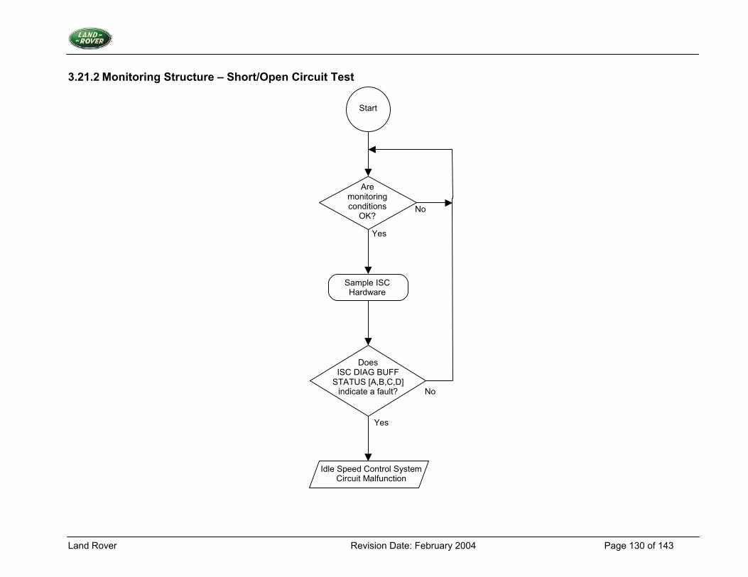
Land Rover Revision Date: February 2004 Page 130 of 143
3.21.2 Monitoring Structure – Short/Open Circuit Test
Start
Yes
No
Sample ISC Hardware
Yes
No
Are monitoringconditions
OK?
Does ISC DIAG BUFF
STATUS [A,B,C,D] indicate a fault?
Idle Speed Control System Circuit Malfunction
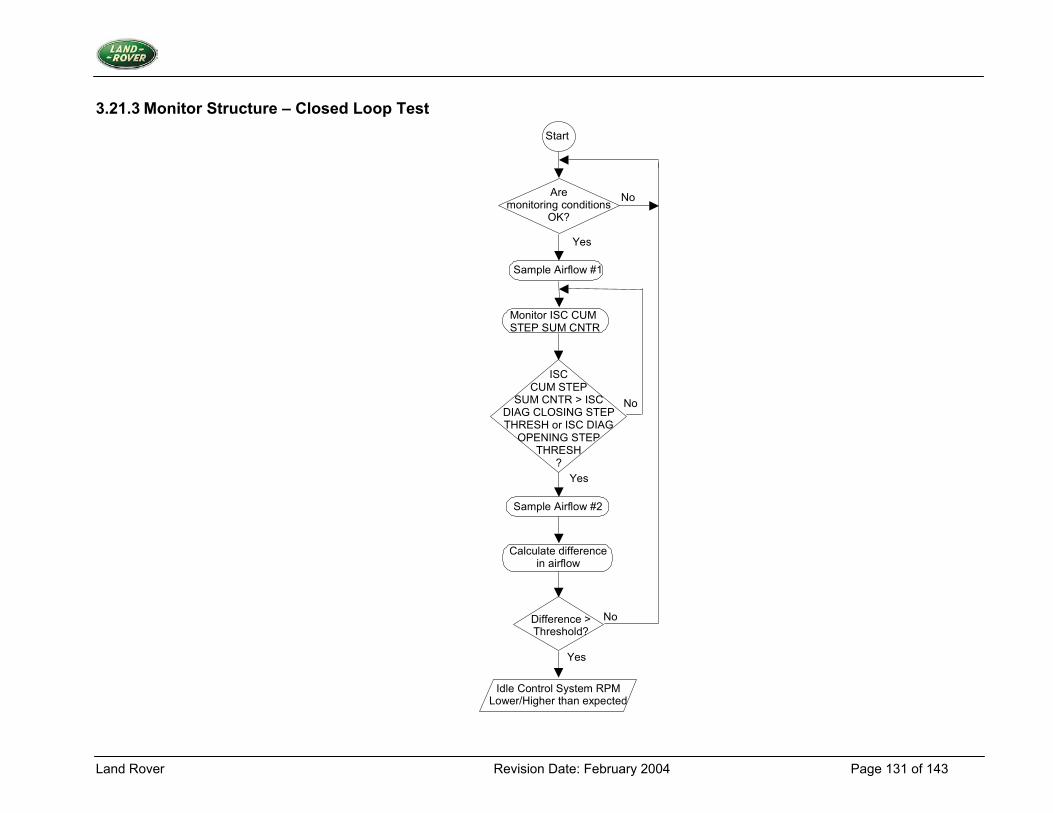
Land Rover Revision Date: February 2004 Page 131 of 143
3.21.3 Monitor Structure – Closed Loop Test Start
Yes
No Are monitoring conditions
OK?
Monitor ISC CUM STEP SUM CNTR
ISC CUM STEP
SUM CNTR > ISC DIAG CLOSING STEP THRESH or ISC DIAG
OPENING STEP THRESH
?
No
Yes
Sample Airflow #1
Sample Airflow #2
Calculate difference in airflow
Difference > Threshold?
Idle Control System RPM Lower/Higher than expected
No
Yes
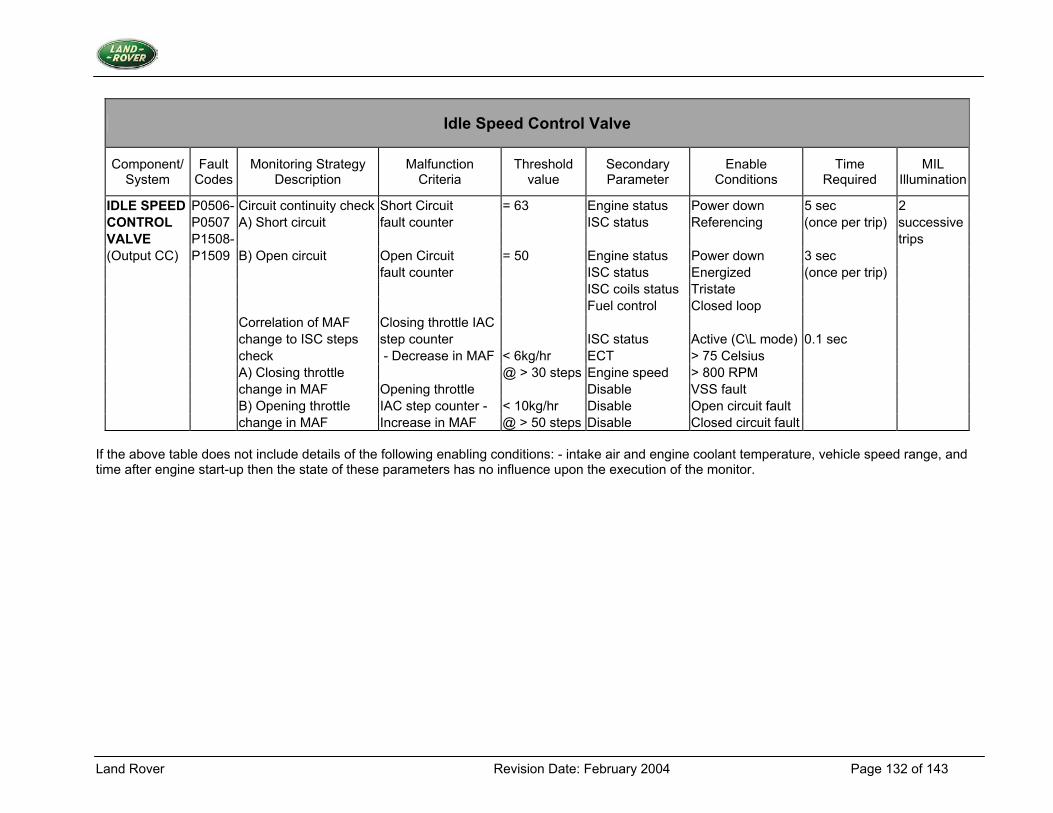
Land Rover Revision Date: February 2004 Page 132 of 143
Idle Speed Control Valve
Component/ System
Fault Codes
Monitoring Strategy Description
Malfunction Criteria
Threshold value
Secondary Parameter
Enable Conditions
Time Required
MIL Illumination
IDLE SPEED P0506- Circuit continuity check Short Circuit = 63 Engine status Power down 5 sec 2 CONTROL P0507 A) Short circuit fault counter ISC status Referencing (once per trip) successiveVALVE P1508- trips (Output CC) P1509 B) Open circuit Open Circuit = 50 Engine status Power down 3 sec fault counter ISC status Energized (once per trip) ISC coils status Tristate Fuel control Closed loop Correlation of MAF Closing throttle IAC change to ISC steps step counter ISC status Active (C\L mode) 0.1 sec check - Decrease in MAF < 6kg/hr ECT > 75 Celsius A) Closing throttle @ > 30 steps Engine speed > 800 RPM change in MAF Opening throttle Disable VSS fault B) Opening throttle IAC step counter - < 10kg/hr Disable Open circuit fault change in MAF Increase in MAF @ > 50 steps Disable Closed circuit fault
If the above table does not include details of the following enabling conditions: - intake air and engine coolant temperature, vehicle speed range, and time after engine start-up then the state of these parameters has no influence upon the execution of the monitor.
Land Rover Revision Date: February 2004 Page 133 of 143
3.22 Malfunction Indicator Lamp (MIL)
3.22.1 Description 1. Diagnostic Trouble Code:
MIL Line Fault P1607 2. Monitoring Procedure Whenever a fault event status is detected from the MIL drive hardware, a fault counter is incremented. When there is no fault event status from the MIL drive hardware the fault counter is decremented. When the fault counter reaches a given threshold there is a MIL lamp open or short circuit fault present. 3. Primary Detection Parameter Hardware fault status from the MIL drive ASIC, which monitors line voltage before low side drive transistor. 4. Fault Criteria Limits 255 continuous fault events detected from the MIL drive ASIC. 5. Monitoring Conditions Continuous 6. Monitoring Time Length / Frequency of Checks The hardware fault status is checked every 10ms. 7. Criteria for Storing a Diagnostic Trouble Code Two successive trips where the diagnostic routines indicate a failed MIL or MIL circuit. 8. Criteria for Illuminating MIL Two successive trips where the diagnostic routines indicate a failed MIL or MIL circuit. 9. Criteria for Determining Out of Range Input Signals The MIL monitoring procedure uses non-linear signals; the criteria will be signal/no signal.
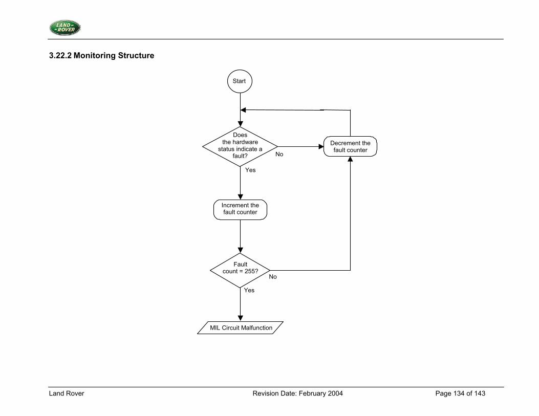
Land Rover Revision Date: February 2004 Page 134 of 143
3.22.2 Monitoring Structure
Start
Yes
Does the hardware
status indicate a fault?
Increment the fault counter
Fault count = 255?
MIL Circuit Malfunction
No
No
Yes
Decrement the fault counter
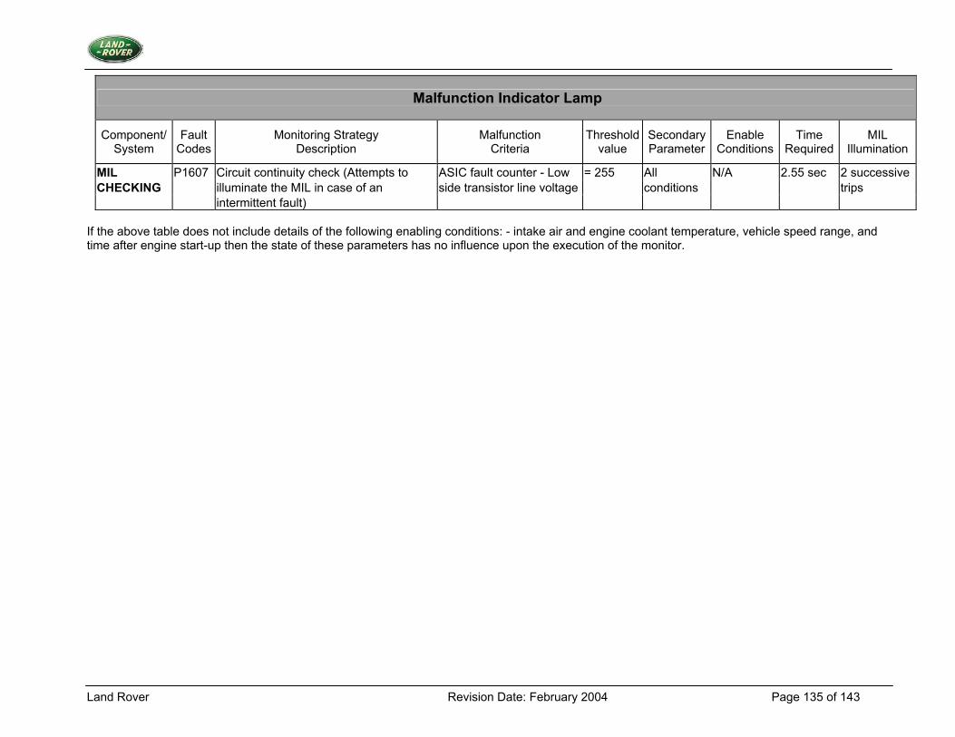
Land Rover Revision Date: February 2004 Page 135 of 143
Malfunction Indicator Lamp
Component/ System
Fault Codes
Monitoring Strategy Description
Malfunction Criteria
Thresholdvalue
SecondaryParameter
Enable Conditions
Time Required
MIL Illumination
MIL P1607 Circuit continuity check (Attempts to ASIC fault counter - Low = 255 All N/A 2.55 sec 2 successive CHECKING illuminate the MIL in case of an side transistor line voltage conditions trips intermittent fault)
If the above table does not include details of the following enabling conditions: - intake air and engine coolant temperature, vehicle speed range, and time after engine start-up then the state of these parameters has no influence upon the execution of the monitor.
Land Rover Revision Date: February 2004 Page 136 of 143
3.23 Ignition Coils
3.23.1 Description 1. Diagnostic Trouble Codes:
Ignition Coil 1 - early ignition coil activation fault P1371 Ignition Coil 2 - early ignition coil activation fault P1372 Ignition Coil 3 - early ignition coil activation fault P1373 Ignition Coil 4 - early ignition coil activation fault P1374 Ignition Coil 1 - no ignition coil activation fault P1361 Ignition Coil 2 - no ignition coil activation fault P1362 Ignition Coil 3 - no ignition coil activation fault P1363 Ignition Coil 4 - no ignition coil activation fault P1364
2. Monitoring Procedure Summary Problems with the ignition coils will be detected using two tests. The tests work by monitoring the coil current status signal when the ignition coils are turned on during normal engine running. The status signal indicates that a threshold coil current has been reached, fully charging the coil. The coils are monitored to detect lack of full charge activation or early activation of the coils, a coil fault event occurring in either case. If these tests are not passed then appropriate fault counter will be incremented, otherwise it will be decremented. If the count reaches a given threshold then a fault is present. No Activation Test. If the coil current status signal has not been asserted between the start and end of the coil activation period then there is a coil fault event, as long as the engine and battery conditions would normally guarantee that the signal would be asserted. Thus a coil fault event occurs if the COIL_CHARGE_EXPECTED flag is set, yet this logic signal was not asserted between the coil turn-on point and the coil turn-off point. If a coil fault event has occurred, the relevant ignition fault event counter is incremented up to a predetermined limit. If this limit is reached then a no ignition coil activation fault is present. If the ignition coil fault event does not occur after a test then the relevant fault event counter is decremented, down to a limit of zero. When a fault event counter reaches zero then there is no fault present. Early Activation Test When the coil is requested to be activated, if the above coil charge signal is asserted earlier than would normally be expected, then there is a coil fault event. Thus a coil fault event occurs if a measured dwell time is less than the minimum expected dwell time. If the relevant fault counter reaches a predetermined limit then an early ignition coil activation fault is present. If the ignition coil fault event does not occur after a test then the relevant ignition fault event counter is decremented, down to a limit of zero. When the fault event counter reaches zero no fault is present.
Land Rover Revision Date: February 2004 Page 137 of 143
3. Primary Detection Parameter Primary coil current status provided by the ignition coil drive ASIC, which compares coil current with a fixed (fully charged coil) threshold. 4. Fault Criteria Limits No Activation Test The presence or not of coil charge status signal within coil turn-on and turn-off point Early Activation Test Minimum expected time to fully charge the coil of 2ms 5. Monitoring Conditions Lack of Activation Test There must be a minimum battery voltage of 10 Volts for either test. There is a maximum engine speed during which the tests will operate, i.e. 3500 rpm, to allow sufficient coil charge discharge time. 6. Monitoring Time Length / Frequency of Checks The tests will be run every engine revolution, (double ended coils). 7. Criteria for Storing a Diagnostic Trouble Code Two successive trips where the diagnostic routine indicates a failed coil/charging circuit. 8. Criteria for Illuminating MIL Two successive trips where the diagnostic routine indicates a failed coil/charging circuit. 9. Criteria for Determining Out of Range Input Signals The coil current status signal is input as a digital high/low signal.
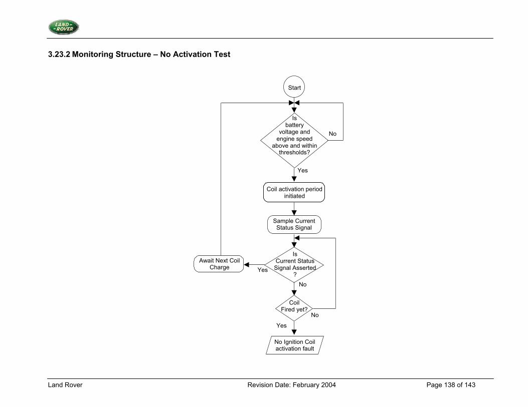
Land Rover Revision Date: February 2004 Page 138 of 143
3.23.2 Monitoring Structure – No Activation Test
Start
Sample Current Status Signal
Is battery
voltage and engine speed
above and within thresholds?
No
Yes
Is Current Status
Signal Asserted ?
No
No Ignition Coil activation fault
Coil Fired yet?
Yes
No
Await Next Coil Charge Yes
Coil activation period initiated
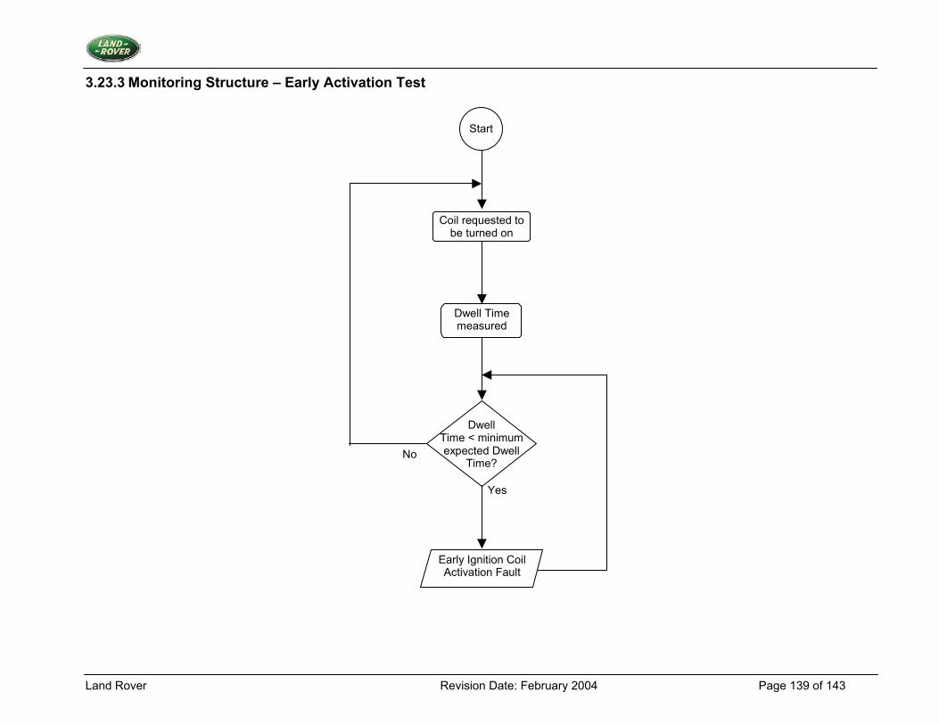
Land Rover Revision Date: February 2004 Page 139 of 143
3.23.3 Monitoring Structure – Early Activation Test
Dwell Time < minimum expected Dwell
Time?
Yes
No
Start
Early Ignition Coil Activation Fault
Coil requested to be turned on
Dwell Time measured
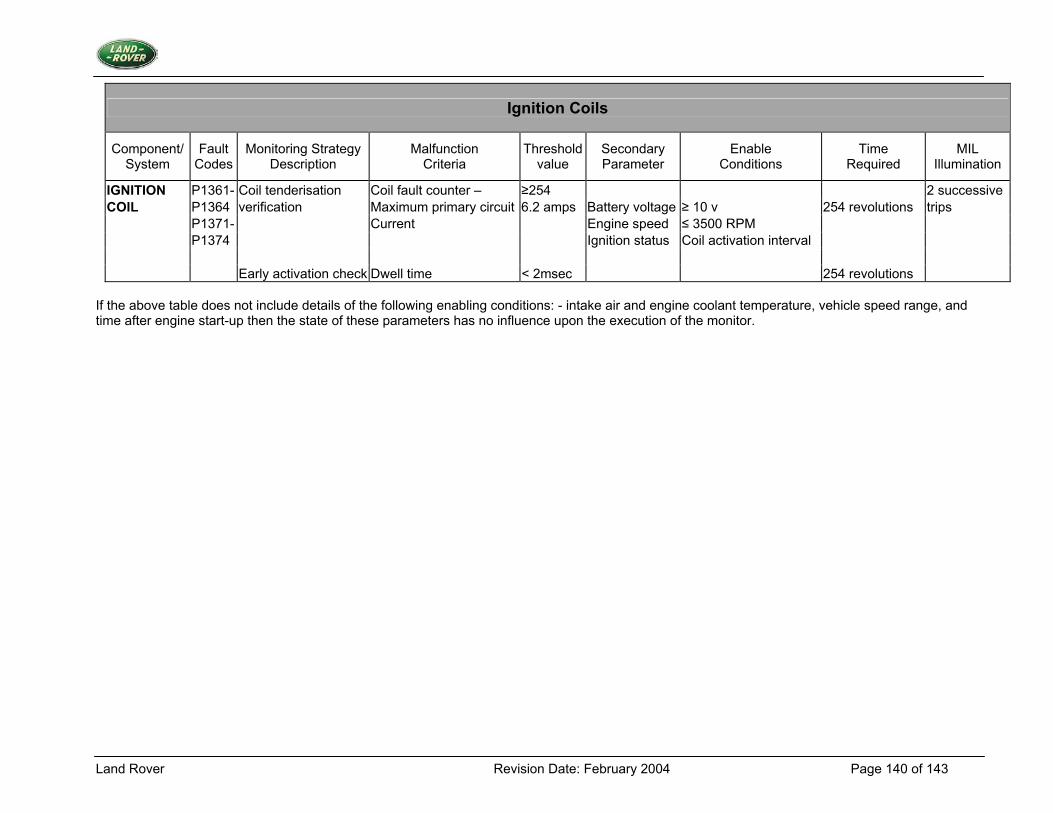
Land Rover Revision Date: February 2004 Page 140 of 143
Ignition Coils
Component/ System
Fault Codes
Monitoring Strategy Description
Malfunction Criteria
Thresholdvalue
Secondary Parameter
Enable Conditions
Time Required
MIL Illumination
IGNITION P1361- Coil tenderisation Coil fault counter – ≥254 2 successive COIL P1364 verification Maximum primary circuit 6.2 amps Battery voltage ≥ 10 v 254 revolutions trips P1371- Current Engine speed ≤ 3500 RPM P1374 Ignition status Coil activation interval Early activation check Dwell time < 2msec 254 revolutions
If the above table does not include details of the following enabling conditions: - intake air and engine coolant temperature, vehicle speed range, and time after engine start-up then the state of these parameters has no influence upon the execution of the monitor.
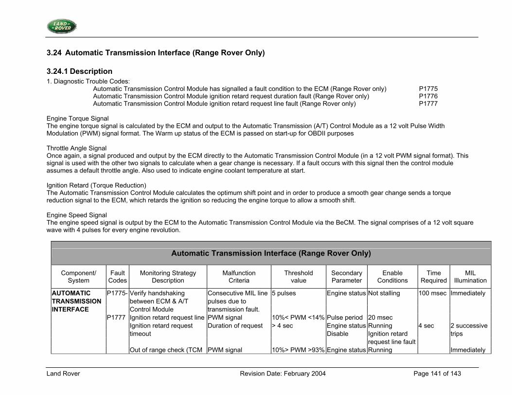
Land Rover Revision Date: February 2004 Page 141 of 143
3.24 Automatic Transmission Interface (Range Rover Only)
3.24.1 Description 1. Diagnostic Trouble Codes:
Automatic Transmission Control Module has signalled a fault condition to the ECM (Range Rover only) P1775 Automatic Transmission Control Module ignition retard request duration fault (Range Rover only) P1776 Automatic Transmission Control Module ignition retard request line fault (Range Rover only) P1777
Engine Torque Signal The engine torque signal is calculated by the ECM and output to the Automatic Transmission (A/T) Control Module as a 12 volt Pulse Width Modulation (PWM) signal format. The Warm up status of the ECM is passed on start-up for OBDII purposes Throttle Angle Signal Once again, a signal produced and output by the ECM directly to the Automatic Transmission Control Module (in a 12 volt PWM signal format). This signal is used with the other two signals to calculate when a gear change is necessary. If a fault occurs with this signal then the control module assumes a default throttle angle. Also used to indicate engine coolant temperature at start. Ignition Retard (Torque Reduction) The Automatic Transmission Control Module calculates the optimum shift point and in order to produce a smooth gear change sends a torque reduction signal to the ECM, which retards the ignition so reducing the engine torque to allow a smooth shift. Engine Speed Signal The engine speed signal is output by the ECM to the Automatic Transmission Control Module via the BeCM. The signal comprises of a 12 volt square wave with 4 pulses for every engine revolution.
Automatic Transmission Interface (Range Rover Only)
Component/ System
Fault Codes
Monitoring Strategy Description
Malfunction Criteria
Threshold value
Secondary Parameter
Enable Conditions
Time Required
MIL Illumination
AUTOMATIC P1775- Verify handshaking Consecutive MIL line 5 pulses Engine status Not stalling 100 msec Immediately TRANSMISSION between ECM & A/T pulses due to INTERFACE Control Module transmission fault. P1777 Ignition retard request line PWM signal 10%< PWM <14% Pulse period 20 msec Ignition retard request Duration of request > 4 sec Engine status Running 4 sec 2 successive timeout Disable Ignition retard trips request line fault Out of range check (TCM PWM signal 10%> PWM >93% Engine status Running Immediately
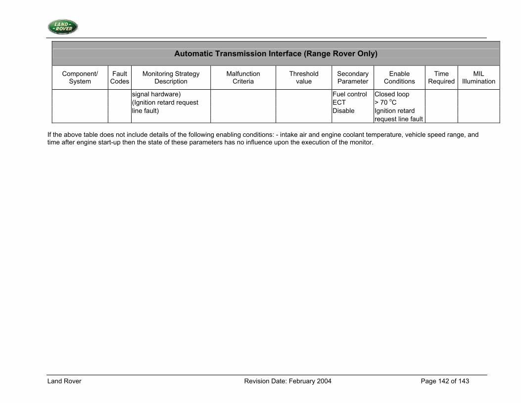
Land Rover Revision Date: February 2004 Page 142 of 143
Automatic Transmission Interface (Range Rover Only)
Component/ System
Fault Codes
Monitoring Strategy Description
Malfunction Criteria
Threshold value
Secondary Parameter
Enable Conditions
Time Required
MIL Illumination
signal hardware) Fuel control Closed loop (Ignition retard request ECT > 70 oC line fault) Disable Ignition retard request line fault
If the above table does not include details of the following enabling conditions: - intake air and engine coolant temperature, vehicle speed range, and time after engine start-up then the state of these parameters has no influence upon the execution of the monitor.
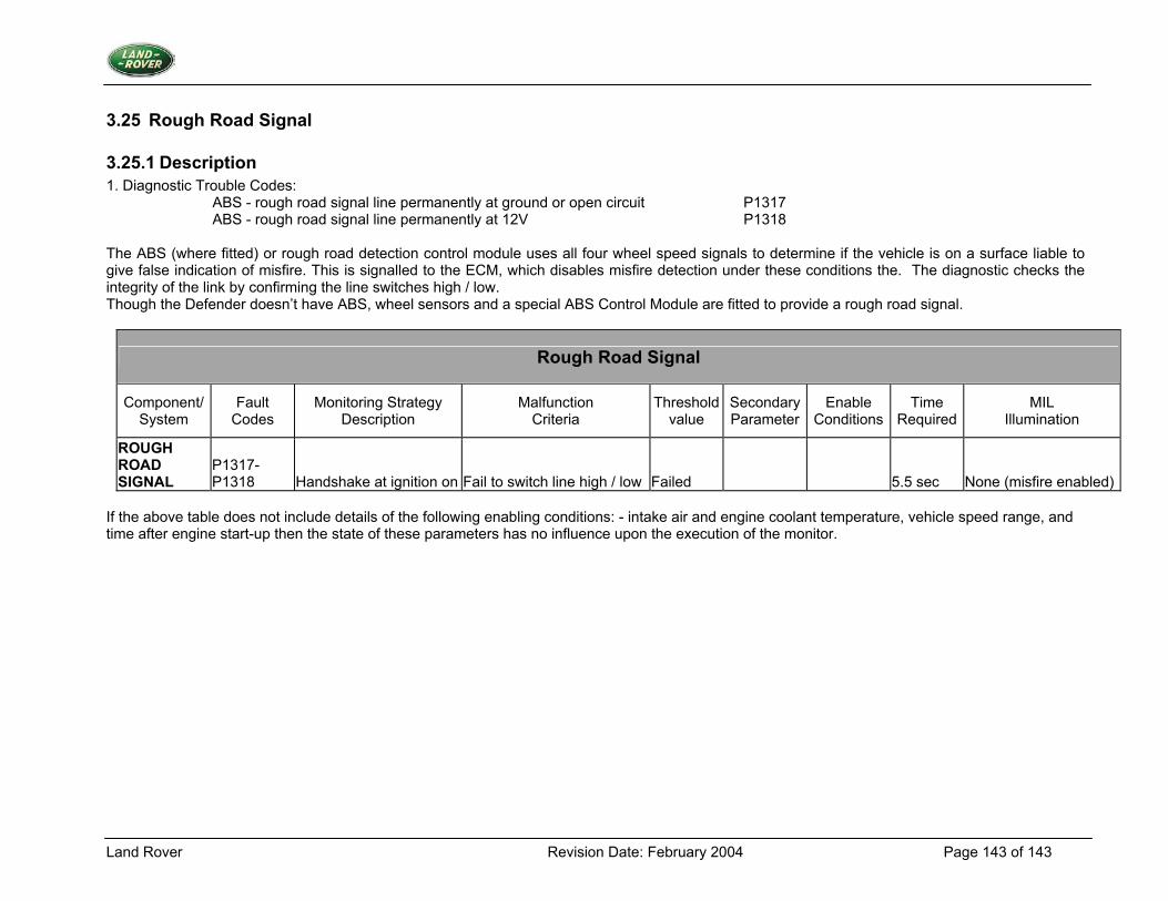
Land Rover Revision Date: February 2004 Page 143 of 143
3.25 Rough Road Signal
3.25.1 Description 1. Diagnostic Trouble Codes:
ABS - rough road signal line permanently at ground or open circuit P1317 ABS - rough road signal line permanently at 12V P1318
The ABS (where fitted) or rough road detection control module uses all four wheel speed signals to determine if the vehicle is on a surface liable to give false indication of misfire. This is signalled to the ECM, which disables misfire detection under these conditions the. The diagnostic checks the integrity of the link by confirming the line switches high / low. Though the Defender doesn’t have ABS, wheel sensors and a special ABS Control Module are fitted to provide a rough road signal.
Rough Road Signal
Component/ System
Fault Codes
Monitoring Strategy Description
Malfunction Criteria
Threshold value
SecondaryParameter
Enable Conditions
Time Required
MIL Illumination
ROUGH ROAD SIGNAL
P1317-P1318 Handshake at ignition on Fail to switch line high / low Failed 5.5 sec None (misfire enabled)
If the above table does not include details of the following enabling conditions: - intake air and engine coolant temperature, vehicle speed range, and time after engine start-up then the state of these parameters has no influence upon the execution of the monitor.