Embed Size (px)
Citation preview
HELIX TECHNOLOGY CORPORATIONMansfield Corporate Center, Nine Hampshire Street, Mansfield, Massachusetts 02048-9171 Telephone (508) 337-5000
CHELIX TECHNOLOGY CORPORATION
-TI CRYOGENICS
On-Board® Cryopump Installation and Maintenance Instructions
8040491Rev. E (9/99)

The information in this document is believed to be accurate and reliable. However, Helix Technology Corporation, cannot accept any financial or other responsibilities that may result from the use of this information. No warranties are granted or extended by this document.
Helix Technology Corporation reserves the right to change any or all information contained herein without prior written notice. Revisions may be issued at the time of such changes and/or deletions.
Any duplication of this manual or any of its parts without expressed written permission from Helix Technology Corporation is strictly prohibited.
Any correspondence regarding this document should be forwarded to:
Helix Technology CorporationMansfield Corporate CenterNine Hampshire StreetMansfield, Massachusetts 02048-9171 U.S.A.
Telephone: (508) 337-5000FAX: (508) 337-5464
The following Helix Technology Corporation trademarks and service marks may appear in this document:
CTI-CRYOGENICS® GUTS®
Cryo-Torr® Cryodyne®
On-Board® RetroFast®
Value Line™ RetroEase®
FastRegen™ TurboPlus®
TurboLink™
ThinLine™
All other trademarks or registered trademarks are the property of their respective holders.
Copyright© 2000 Helix Technology Corporation Printed in U.S.A.

On-Board Cryopump Installation and Maintenance Instructions
P/N 8040491 iii
CHELIX TECHNOLOGY CORPORATION
-TI CRYOGENICS
Table of Contents
SafetyIntroduction . . . . . . . . . . . . . . . . . . . . . . . . . . . . . . . . . . . . . . . . . . . . . . . . . . . . . . . S-1Warnings . . . . . . . . . . . . . . . . . . . . . . . . . . . . . . . . . . . . . . . . . . . . . . . . . . . . . . . . . S-1
Toxic, Corrosive, Dangerous Gases, or Liquids . . . . . . . . . . . . . . . . . . . . . . . . S-1Flammable or Explosive Gases . . . . . . . . . . . . . . . . . . . . . . . . . . . . . . . . . . . . . S-1High Voltage . . . . . . . . . . . . . . . . . . . . . . . . . . . . . . . . . . . . . . . . . . . . . . . . . . . S-2High Gas Pressure . . . . . . . . . . . . . . . . . . . . . . . . . . . . . . . . . . . . . . . . . . . . . . . S-2
Cautions . . . . . . . . . . . . . . . . . . . . . . . . . . . . . . . . . . . . . . . . . . . . . . . . . . . . . . . . . . S-2Cryopump Oxygen Procedures . . . . . . . . . . . . . . . . . . . . . . . . . . . . . . . . . . . . . . . . S-2
Section 1 - On-Board Cryopump DescriptionIntroduction . . . . . . . . . . . . . . . . . . . . . . . . . . . . . . . . . . . . . . . . . . . . . . . . . . . . . . . 1-1Installation, Operation, and Maintenance Instructions . . . . . . . . . . . . . . . . . . . . . . 1-1Microprocessor-Based Control System . . . . . . . . . . . . . . . . . . . . . . . . . . . . . . . . . . 1-1
Remote Operation Options . . . . . . . . . . . . . . . . . . . . . . . . . . . . . . . . . . . . . . . . 1-2Specifications . . . . . . . . . . . . . . . . . . . . . . . . . . . . . . . . . . . . . . . . . . . . . . . . . . . . . . 1-5 Theory of Operation . . . . . . . . . . . . . . . . . . . . . . . . . . . . . . . . . . . . . . . . . . . . . . . 1-14
Cold Head . . . . . . . . . . . . . . . . . . . . . . . . . . . . . . . . . . . . . . . . . . . . . . . . . . . . 1-14Vacuum Vessel and Arrays . . . . . . . . . . . . . . . . . . . . . . . . . . . . . . . . . . . . . . . 1-14Compressor Gas and Oil Flows . . . . . . . . . . . . . . . . . . . . . . . . . . . . . . . . . . . . 1-14
Section 2 - InstallationIntroduction . . . . . . . . . . . . . . . . . . . . . . . . . . . . . . . . . . . . . . . . . . . . . . . . . . . . . . . 2-1Keypad/Display Installation . . . . . . . . . . . . . . . . . . . . . . . . . . . . . . . . . . . . . . . . . . 2-2
Position A . . . . . . . . . . . . . . . . . . . . . . . . . . . . . . . . . . . . . . . . . . . . . . . . . . . . . 2-2Position B . . . . . . . . . . . . . . . . . . . . . . . . . . . . . . . . . . . . . . . . . . . . . . . . . . . . . . 2-3Position C . . . . . . . . . . . . . . . . . . . . . . . . . . . . . . . . . . . . . . . . . . . . . . . . . . . . . . 2-4Position D . . . . . . . . . . . . . . . . . . . . . . . . . . . . . . . . . . . . . . . . . . . . . . . . . . . . . 2-5
On-Board Cryopump Installation . . . . . . . . . . . . . . . . . . . . . . . . . . . . . . . . . . . . . . 2-6Vent Pipe Connection . . . . . . . . . . . . . . . . . . . . . . . . . . . . . . . . . . . . . . . . . . . . 2-6Roughing Pump Connection . . . . . . . . . . . . . . . . . . . . . . . . . . . . . . . . . . . . . . . 2-7Rough Valve Gas Connection . . . . . . . . . . . . . . . . . . . . . . . . . . . . . . . . . . . . . . 2-7Purge Gas Connection . . . . . . . . . . . . . . . . . . . . . . . . . . . . . . . . . . . . . . . . . . . . 2-7Helium Line Connections . . . . . . . . . . . . . . . . . . . . . . . . . . . . . . . . . . . . . . . . . 2-7Auxiliary (AUX) TC Gauge Installation . . . . . . . . . . . . . . . . . . . . . . . . . . . . . . 2-8
Setpoint Relays . . . . . . . . . . . . . . . . . . . . . . . . . . . . . . . . . . . . . . . . . . . . . . . . . . . . 2-8Remote Keypad/Display Installation (Optional) . . . . . . . . . . . . . . . . . . . . . . . . . . 2-10

On-Board Cryopump Installation and Maintenance Instructions
iv P/N 8040491
CHELIX TECHNOLOGY CORPORATION
-TI CRYOGENICS
Table of Contents (continued)
Section 3 - TroubleshootingTechnical Inquiries . . . . . . . . . . . . . . . . . . . . . . . . . . . . . . . . . . . . . . . . . . . . . . . . . 3-1
Section 4 - MaintenanceHelium Circuit Decontamination . . . . . . . . . . . . . . . . . . . . . . . . . . . . . . . . . . . . . . . 4-1
Background . . . . . . . . . . . . . . . . . . . . . . . . . . . . . . . . . . . . . . . . . . . . . . . . . . . . 4-2Equipment/Tools Requirements . . . . . . . . . . . . . . . . . . . . . . . . . . . . . . . . . . . . 4-3Method 1 - Decontaminate all On-Board Cryopumps . . . . . . . . . . . . . . . . . . . . 4-6
Decontamination Alternatives . . . . . . . . . . . . . . . . . . . . . . . . . . . . . . . . . . . . . . . . 4-10Method #1 Decontaminate All Cryopumps . . . . . . . . . . . . . . . . . . . . . . . . . . . 4-10Method # 2 Decontamination of Only Cold Cryopumps . . . . . . . . . . . . . . . . 4-10
Step 1 - Method #2 . . . . . . . . . . . . . . . . . . . . . . . . . . . . . . . . . . . . . . . . . . . 4-11Step 17 - Method #2 . . . . . . . . . . . . . . . . . . . . . . . . . . . . . . . . . . . . . . . . . . 4-11
Method # 3 Grouped Decontamination using Manifold . . . . . . . . . . . . . . . . . 4-11Step 5 - Method #3 . . . . . . . . . . . . . . . . . . . . . . . . . . . . . . . . . . . . . . . . . . . 4-11Step 6 - Method #3 . . . . . . . . . . . . . . . . . . . . . . . . . . . . . . . . . . . . . . . . . . . 4-12Step 10- Method #3. . . . . . . . . . . . . . . . . . . . . . . . . . . . . . . . . . . . . . . . . . . 4-12Steps 11 - 16 - Method #3. . . . . . . . . . . . . . . . . . . . . . . . . . . . . . . . . . . . . . 4-12
On-Board Cryopump Cleaning . . . . . . . . . . . . . . . . . . . . . . . . . . . . . . . . . . . . . . . 4-15
Appendix A - Customer Support Centers
Figures
Figure 1-1: On-Board Cryopumps . . . . . . . . . . . . . . . . . . . . . . . . . . . . . . . . . . . 1-3Figure 1-2: On-Board Cryopumps . . . . . . . . . . . . . . . . . . . . . . . . . . . . . . . . . . . 1-4Figure 1-3: Typical On-Board Cryopump System . . . . . . . . . . . . . . . . . . . . . 1-15Figure 1-4: Cutaway View of a Typical Flat On-Board Cryopump Vessel . . 1-16Figure 1-5: Cutaway View of a Typical Straight On-Board Cryopump Vessel 1-17Figure 1-6: Typical Flat On-Board Cryopump Component Identification . . . 1-18Figure 1-7: Typical Straight On-Board Cryopump Component Identification 1-19
Figure 2-1: Block Diagram for On-Board Cryopump Installation . . . . . . . . . . 2-1Figure 2-2: Keypad/Display Mounting Position A . . . . . . . . . . . . . . . . . . . . . . 2-2Figure 2-3: Keypad/Display Mounting Position B . . . . . . . . . . . . . . . . . . . . . . 2-3Figure 2-4: Keypad/Display Mounting Position C . . . . . . . . . . . . . . . . . . . . . . 2-4Figure 2-5: Keypad/Display Mounting Position D . . . . . . . . . . . . . . . . . . . . . . 2-5Figure 2-6: Setpoint Relays Connection and Pin Identification . . . . . . . . . . . . 2-9

On-Board Cryopump Installation and Maintenance Instructions
P/N 8040491 v
CHELIX TECHNOLOGY CORPORATION
-TI CRYOGENICS
Table of Contents (continued)
Figure 4-1: Decontamination Flowchart . . . . . . . . . . . . . . . . . . . . . . . . . . . . . . 4-4Figure 4-2: On-Board Cryopump Helium Supply and Return Lines . . . . . . . . . 4-8Figure 4-3: Maintenance Manifold Part Number 8032051G001 . . . . . . . . . . . 4-13Figure 4-4: Proper Helium Line Coupling Disconnection/Connection . . . . . . 4-14
Tables
Table 1-1:On-Board 8F High-Vacuum Cryopump Specifications . . . . . . . . . . 1-5Table 1-2:On-Board 8 High-Vacuum Cryopump Specifications . . . . . . . . . . . 1-6Table 1-3:On-Board 6 High-Vacuum Cryopump Specifications . . . . . . . . . . . 1-7Table 1-4:On-Board 4 High-Vacuum Cryopump Specifications . . . . . . . . . . . 1-8Table 1-5:On-Board 250F High-Vacuum Cryopump Specifications . . . . . . . . 1-9Table 1-6:On-Board 4F High-Vacuum Cryopump Specifications . . . . . . . . . 1-10Table 1-7:On-Board 10 High-Vacuum Cryopump Specifications . . . . . . . . . 1-11Table 1-8:On-Board 10F High-Vacuum Cryopump Specifications . . . . . . . . 1-12Table 1-9:On-Board 400 High-Vacuum Cryopump Specifications . . . . . . . . 1-13
Table 3-1:Cryopump Troubleshooting Procedures . . . . . . . . . . . . . . . . . . . . . . 3-2Table 3-1:Troubleshooting Procedures (continued) . . . . . . . . . . . . . . . . . . . . . 3-3
Table 4-1:Methods of Decontamination . . . . . . . . . . . . . . . . . . . . . . . . . . . . . . 4-1Table 4-2:Decontamination Tools and Equipment . . . . . . . . . . . . . . . . . . . . . . 4-3Table 4-3:Indium Gasket Screw Torque Specifications . . . . . . . . . . . . . . . . . 4-16
Table A-1:Customer Support Center Locations . . . . . . . . . . . . . . . . . . . . . . . . A-2
Safety
S-1
CHELIX TECHNOLOGY CORPORATION
-TI CRYOGENICS
Safety
Introduction
On-Board products have been designed to provide extremely safe and dependable operation when properly used. Safety precautions must be observed during normal operation and when servicing the On-Board system.
NOTE: Read this manual and follow these safety guidelines before installing, operating, or servicing On-Board products.
Warnings
A warning describes safety hazards or unsafe practices which could result in personal injury or loss of life. A warning message is accompanied by a symbol as described in the following paragraphs and is also surrounded by a box to attract your attention.
Toxic, Corrosive, Dangerous Gases, or Liquids
Toxic, corrosive, dangerous gases, or liquids which may be present in an On-Board product could cause severe injury upon contact. Make sure the following precautions are taken when handling toxic, corrosive, or dangerous gases.
1. Always vent toxic, corrosive, dangerous gases, or liquids to a safe location using an inert purge gas.
2. Clearly identify toxic, corrosive, dangerous gases, or liquids on containers used to store or ship equipment after such exposure.
Flammable or Explosive Gases
Flammable or explosive gases which may be present in an On-Board product could cause severe injury if ignited. Make sure the following precautions are taken when handling flammable or explosive gases:
1. Always vent flammable or explosive gases to a safe location using an inert purge gas.
2. Do not install a hot filament type vacuum gauge on the high vacuum side of the isolation valve. This could be an ignition source of flammable gases in On-Board products.
Safety
S-2
CHELIX TECHNOLOGY CORPORATION
-TI CRYOGENICS
High Voltage
High voltage electric shock can cause severe injury or loss of life. Take the following precautions to prevent high voltage risks:
1. Disconnect the high vacuum pump system from all power sources before making electrical connections between system components or before performing troubleshooting and mainte-nance procedures.
High Gas Pressure
High gas pressure may be present within high vacuum pump systems and can cause severe injury from propelled particles or parts.
1. Do not modify or remove the pressure relief valves, either on the On-Board pump or within the helium compressor.
2. Always depressurize the adsorber to atmospheric pressure before disposing.
3. Always bleed the helium charge down to atmospheric pressure before servicing or disassembling the self sealing couplings.
Cautions
A caution describes safety hazards or unsafe practices which could result in equipment damage.
Cryopump Oxygen Procedures
WARNINGCombustion supported by oxygen in the cryopump could causesevere injury when oxygen is used as a process gas. Special precau-tions described in the following text should be taken.
When oxygen is used as a process gas, the following precautions should be taken:
1. Insure that there are no sources of ignition (e.g. hot filament vacuum gauges) on the cryopump side of the high vacuum valve operating during the warming or venting of the cryopump.

Safety
S-3
CHELIX TECHNOLOGY CORPORATION
-TI CRYOGENICS
2. Perform inert gas purge regeneration cycles at flow rates recom-mended for cryopumps.
3. Regenerate as frequently as practical to minimize the amount of oxidizer present in the cryopump.
4. It is standard practice in the vacuum industry that any system exposed to richer-than-air oxygen levels should be prepared for oxygen service per the manufacturer’s recommendations, including use of oxygen service lubricating oils in roughing pumps.
WARNINGExplosion occurring from ozone in the cryopump could cause severe injury. Ozone can be present as a by product of oxygen processes. If ozone is present, special precautions described in the following text must be taken.
Ozone may be unknowingly produced in an ionizing process (e.g. sputter-ing, etching, glow discharge). Explosive conditions may exist if ozone is present, especially during the warming of the cryopump. Signs of ozone’s presence are:
1. Crackling, popping sounds (as in electrical arcing) occurring within the first few minutes of a regeneration cycle.
2. Gas venting from the cryopump during regeneration may have a pungent smell, similar to that present in an arc welding operation or after an electrical storm.
NOTE: A change in process may increase the amount of ozone present.
If ozone is present, the following precautions must be taken:
1. All of the above oxygen precautions must be followed. The required regeneration frequency is dependent upon flow and process conditions. Daily regeneration may be required. Call CTI-CRYOGENICS for assistance.
2. Reduce the oxygen mixture to the lowest level the process will allow.
On-Board Cryopump Installation and Maintenance Instructions
P/N 8040491 1-1
CHELIX TECHNOLOGY CORPORATION
-TI CRYOGENICS
Section 1 - On-Board Cryopump Description
Introduction
On-Board Cryopumps provide fast, clean pumping of all gases in the 10-3 to 10-9 torr range. An On-Board Cryopump operates on the principle that gases can be condensed and held at extremely low vapor pressures, achieving high speeds and throughputs as described in Tables 1-1 - 1-9.
The On-Board Cryopump is a highly-reliable and rugged unit that requires little maintenance. Since the On-Board Cryopump exposes no moving parts, operating fluids, or backing pumps to the vacuum, the possibility of system or process contamination from the On-Board Cryopump is eliminated.
Installation, Operation, and Maintenance Instructions
Installation, Operation, and Maintenance Instructions for your On-Board Cryopump provide easily accessible information. All personnel with installation, operation, and maintenance responsibilities should become familiar with the contents of these instructions to ensure safe, reliable, and high performance.
Microprocessor-Based Control System
The On-Board Cryopump is equipped with a microprocessor-based control system that allows you to both monitor and control a wide range of important vacuum system functions. Operations are performed on a keypad control/display panel that is mounted right on the cryopump. You can monitor and control cooldown, warm-up, regeneration, etc.
Refer to appropriate On-Board Module Programming and Operation Instructions, that came with your On-Board Cryopump, for a complete description of the numerous operational functions that are available.
On-Board Cryopump Description
P/N 8040491 1-2
CHELIX TECHNOLOGY CORPORATION
-TI CRYOGENICS
Remote Operation Options
A remote keypad/display is available which provides the same functions as the basic On-Board keypad/display.
On-Board Cryopumps can be controlled remotely using either a BITBUS™ or RS-232 protocol. The most common implementation, used in multiple On-Board Cryopump process tools, is to network the On-Board Cryopumps using the BITBUS™ protocol. In this configuration, the networked On-Board Cryopumps are managed as a group by the On-Board Network Terminal, which coordinates group regeneration cycles and provides a standardized communication link to the process tool host controller. Using this approach, control of the networked On-Board Cryopumps is fully integrated with process tool control.
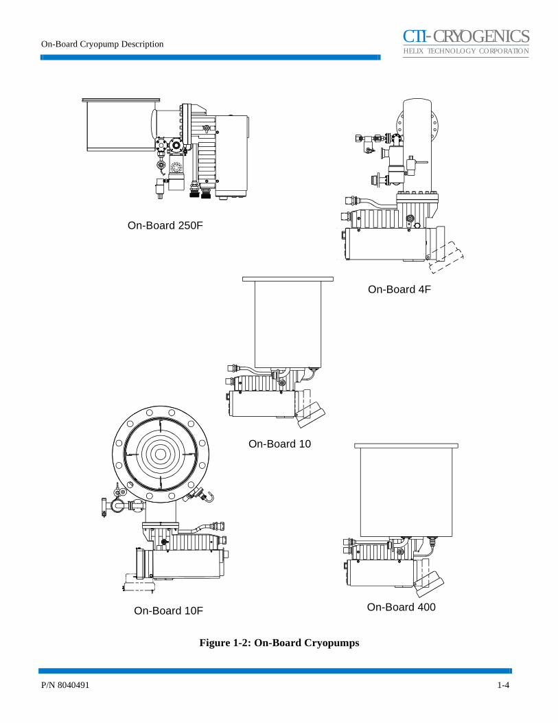
On-Board Cryopumps are available in a range of sizes and configurations to address different applications as shown in Figures 1-1 and 1-2. The specifications for each On-Board Cryopump are provided in Tables 1-1 - 1-9.

On-Board Cryopump Installation and Maintenance Instructions
P/N 8040491 1-3
CHELIX TECHNOLOGY CORPORATION
-TI CRYOGENICS
Figure 1-1: On-Board Cryopumps
On-Board 8
On-Board 8F
On-Board 4On-Board 6
On-Board Cryopump Description
P/N 8040491 1-4
CHELIX TECHNOLOGY CORPORATION
-TI CRYOGENICS
Figure 1-2: On-Board Cryopumps
On-Board 4F
On-Board 250F
On-Board 10F On-Board 400
On-Board 10

On-Board Cryopump Installation and Maintenance Instructions
P/N 8040491 1-5
CHELIX TECHNOLOGY CORPORATION
-TI CRYOGENICS
Specifications
Table 1-1: On-Board 8F High-Vacuum Cryopump Specifications
Parameter Specifications
Rough Pump Connection NW 25 ISO KF
Integrated Hardware Keypad/DisplayRoughing ValvePurge ValveCryopump TC Gauge1st Stage Diode2nd Stage Diode1st Stage Heater2nd Stage Heater2 Setpoint RelaysRS-232 Interface
Pumping Speeds:Water
AirHydrogen
Argon
4000 liters/sec1500 liters/sec2200 liters/sec1200 liters/sec
Argon Throughput 700 sccm (9 torr-liters/sec)
Capacity:Argon
Hydrogen1000 std. liters12 std. liters @ 5 x 10⁻⁶ torr
Crossover 150 torr-liters
Cooldown Time 2 hours nominal
Dimensions Refer to Installation/Interface Drawing
Weight 63 lbs.
On-Board Cryopump Description
P/N 8040491 1-6
CHELIX TECHNOLOGY CORPORATION
-TI CRYOGENICS
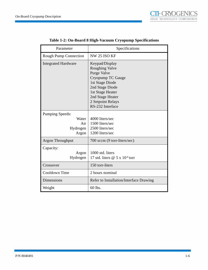
Table 1-2: On-Board 8 High-Vacuum Cryopump Specifications
Parameter Specifications
Rough Pump Connection NW 25 ISO KF
Integrated Hardware Keypad/DisplayRoughing ValvePurge ValveCryopump TC Gauge1st Stage Diode2nd Stage Diode1st Stage Heater2nd Stage Heater2 Setpoint RelaysRS-232 Interface
Pumping Speeds:Water
AirHydrogen
Argon
4000 liters/sec1500 liters/sec2500 liters/sec1200 liters/sec
Argon Throughput 700 sccm (9 torr-liters/sec)
Capacity:Argon
Hydrogen1000 std. liters17 std. liters @ 5 x 10⁻⁶ torr
Crossover 150 torr-liters
Cooldown Time 2 hours nominal
Dimensions Refer to Installation/Interface Drawing
Weight 60 lbs.
On-Board Cryopump Installation and Maintenance Instructions
P/N 8040491 1-7
CHELIX TECHNOLOGY CORPORATION
-TI CRYOGENICS
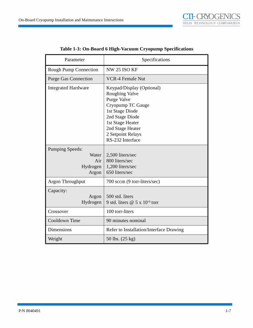
Table 1-3: On-Board 6 High-Vacuum Cryopump Specifications
Parameter Specifications
Rough Pump Connection NW 25 ISO KF
Purge Gas Connection VCR-4 Female Nut
Integrated Hardware Keypad/Display (Optional)Roughing ValvePurge ValveCryopump TC Gauge1st Stage Diode2nd Stage Diode1st Stage Heater2nd Stage Heater2 Setpoint RelaysRS-232 Interface
Pumping Speeds:Water
AirHydrogen
Argon
2,500 liters/sec800 liters/sec1,200 liters/sec650 liters/sec
Argon Throughput 700 sccm (9 torr-liters/sec)
Capacity:Argon
Hydrogen500 std. liters9 std. liters @ 5 x 10⁻⁶ torr
Crossover 100 torr-liters
Cooldown Time 90 minutes nominal
Dimensions Refer to Installation/Interface Drawing
Weight 50 lbs. (25 kg)
On-Board Cryopump Description
P/N 8040491 1-8
CHELIX TECHNOLOGY CORPORATION
-TI CRYOGENICS
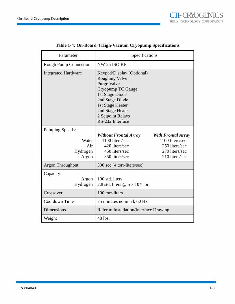
Table 1-4: On-Board 4 High-Vacuum Cryopump Specifications
Parameter Specifications
Rough Pump Connection NW 25 ISO KF
Integrated Hardware Keypad/Display (Optional)Roughing ValvePurge ValveCryopump TC Gauge1st Stage Diode2nd Stage Diode1st Stage Heater2nd Stage Heater2 Setpoint RelaysRS-232 Interface
Pumping Speeds:
WaterAir
HydrogenArgon
Without Frontal Array With Frontal Array 1100 liters/sec 1100 liters/sec 420 liters/sec 250 liters/sec 450 liters/sec 270 liters/sec 350 liters/sec 210 liters/sec
Argon Throughput 300 scc (4 torr-liters/sec)
Capacity:Argon
Hydrogen100 std. liters2.8 std. liters @ 5 x 10⁻⁶ torr
Crossover 100 torr-liters
Cooldown Time 75 minutes nominal, 60 Hz
Dimensions Refer to Installation/Interface Drawing
Weight 48 lbs.

On-Board Cryopump Installation and Maintenance Instructions
P/N 8040491 1-9
CHELIX TECHNOLOGY CORPORATION
-TI CRYOGENICS
Table 1-5: On-Board 250F High-Vacuum Cryopump Specifications
Parameter Specifications
Rough Pump Connection NW 25 ISO KF
Integrated Hardware Keypad/DisplayRoughing ValvePurge ValveCryopump TC Gauge1st Stage Diode2nd Stage Diode1st Stage Heater2nd Stage Heater2 Setpoint RelaysRS-232 Interface
Pumping Speeds:Water
AirHydrogen
Argon
6500 liters/sec1900 liters/sec4800 liters/sec1700 liters/sec
Argon Throughput 700 sccm (9 torr-liters/sec)
Capacity:Argon
Hydrogen1000 std. liters15 std. liters @ 5 x 10⁻⁶ torr
Crossover 200 torr-liters
Cooldown Time 2.5 hours nominal
Dimensions Refer to Installation/Interface Drawing
Weight 70 lbs.
On-Board Cryopump Description
P/N 8040491 1-10
CHELIX TECHNOLOGY CORPORATION
-TI CRYOGENICS
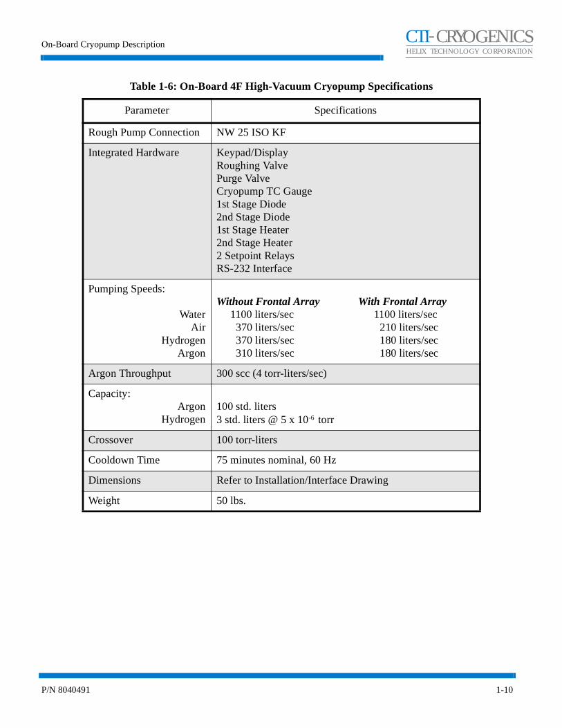
Table 1-6: On-Board 4F High-Vacuum Cryopump Specifications
Parameter Specifications
Rough Pump Connection NW 25 ISO KF
Integrated Hardware Keypad/DisplayRoughing ValvePurge ValveCryopump TC Gauge1st Stage Diode2nd Stage Diode1st Stage Heater2nd Stage Heater2 Setpoint RelaysRS-232 Interface
Pumping Speeds:
WaterAir
HydrogenArgon
Without Frontal Array With Frontal Array 1100 liters/sec 1100 liters/sec 370 liters/sec 210 liters/sec 370 liters/sec 180 liters/sec 310 liters/sec 180 liters/sec
Argon Throughput 300 scc (4 torr-liters/sec)
Capacity:Argon
Hydrogen100 std. liters3 std. liters @ 5 x 10⁻⁶ torr
Crossover 100 torr-liters
Cooldown Time 75 minutes nominal, 60 Hz
Dimensions Refer to Installation/Interface Drawing
Weight 50 lbs.
On-Board Cryopump Installation and Maintenance Instructions
P/N 8040491 1-11
CHELIX TECHNOLOGY CORPORATION
-TI CRYOGENICS
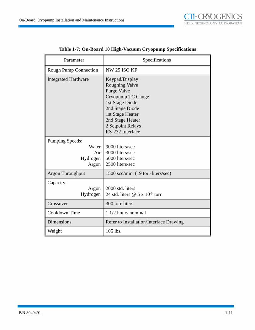
Table 1-7: On-Board 10 High-Vacuum Cryopump Specifications
Parameter Specifications
Rough Pump Connection NW 25 ISO KF
Integrated Hardware Keypad/DisplayRoughing ValvePurge ValveCryopump TC Gauge1st Stage Diode2nd Stage Diode1st Stage Heater2nd Stage Heater2 Setpoint RelaysRS-232 Interface
Pumping Speeds:Water
AirHydrogen
Argon
9000 liters/sec3000 liters/sec5000 liters/sec2500 liters/sec
Argon Throughput 1500 scc/min. (19 torr-liters/sec)
Capacity:Argon
Hydrogen2000 std. liters24 std. liters @ 5 x 10⁻⁶ torr
Crossover 300 torr-liters
Cooldown Time 1 1/2 hours nominal
Dimensions Refer to Installation/Interface Drawing
Weight 105 lbs.

On-Board Cryopump Description
P/N 8040491 1-12
CHELIX TECHNOLOGY CORPORATION
-TI CRYOGENICS
Table 1-8: On-Board 10F High-Vacuum Cryopump Specifications
Parameter Specifications
Rough Pump Connection NW 25 ISO KF
Integrated Hardware Keypad/DisplayRoughing ValvePurge ValveCryopump TC Gauge1st Stage Diode2nd Stage Diode1st Stage Heater2nd Stage Heater2 Setpoint RelaysRS-232 Interface
Pumping Speeds:Water
AirHydrogen
Argon
9500 liters/sec4000 liters/sec6800 liters/sec3300 liters/sec
Argon Throughput 1500 scc/min. (19 torr-liters/sec)
Capacity:Argon
Hydrogen2000 std. liters; 1,500,000 torr-liters24 std. liters @ 5 x 10⁻⁶ torr
Crossover 300 torr-liters
Cooldown Time 1 hour, 40 minutes nominal
Dimensions Refer to Installation/Interface Drawing
Weight 90 lbs.

On-Board Cryopump Installation and Maintenance Instructions
P/N 8040491 1-13
CHELIX TECHNOLOGY CORPORATION
-TI CRYOGENICS
Table 1-9: On-Board 400 High-Vacuum Cryopump Specifications
Parameter Specifications
Rough Pump Connection NW 25 ISO KF
Integrated Hardware Keypad/DisplayRoughing ValvePurge ValveCryopump TC Gauge1st Stage Diode2nd Stage Diode2nd Stage Heater2 Setpoint RelaysRS-232 Interface
Pumping Speeds:Water
AirHydrogen
Argon
16,000 liters/sec6,000 liters/sec12,000 liters/sec5,000 liters/sec
Argon Throughput 500 scc/min (6.3 torr-liters/sec)
CapacityArgon
Hydrogen2500 std. liters30 std. liters @ 5 x 10⁻⁶ torr
Crossover 300 torr-liters
Cooldown Time 2 1/2 hours nominal
Dimensions Refer to Installation/Interface Drawing
Weight 175 lbs.

On-Board Cryopump Description
P/N 8040491 1-14
CHELIX TECHNOLOGY CORPORATION
-TI CRYOGENICS
Theory of Operation
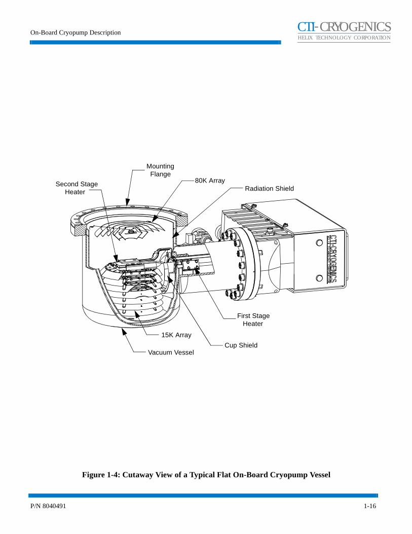
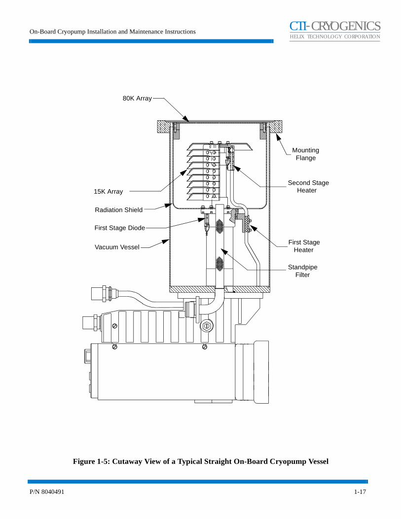
Each On-Board Cryopump consists of a cold head and a vacuum vessel as shown in Figures 1-4 or 1-5. An 80K condensing array, a 15K array, cold head station heaters, and an 80K radiation shield are located in the vacuum vessel. The cold station heaters and 15K array are secured to the cold head, which is welded to the vacuum vessel. The cold head provides cooling to the three arrays. Gases are removed from your vacuum chamber, thereby creating a vacuum when they are condensed or adsorbed on the cryogenically-cooled arrays.
Cold Head
The cold head consists of a two-stage cold head cylinder (part of the vacuum vessel) and drive unit displacer assembly, that together produce closed-cycle refrigeration at temperatures that range from 60 to 120K for the first-stage cold station and 10 to 20K for the second-stage cold station, depending on operating conditions. Within the drive unit displacer assembly, the drive unit actuates the displacer-regenerator assembly located in the cold head cylinder and thereby controls the flow of helium into the cold head. Within the drive unit are located the crankcase and drive motor, which is a direct-drive constant-speed motor, operating at 72 rpm on 60 Hz power and 60 rpm on 50 Hz power.
During operation, high pressure helium from the compressor enters the cold head at the helium supply connector, and flows through the displacer-regenerator assembly, crankcase, and motor housing before exiting through the helium gas return connector and returning to the compressor. Helium expansion in the displacer-regenerator assembly provides cooling at the first and second stage cold stations.
Vacuum Vessel and Arrays
The 80K array, as shown in Figures 1-4 or 1-5, condenses water and hydrocarbon vapors. The 15K array condenses nitrogen, oxygen, and argon while the specially processed charcoal of this array traps helium, hydrogen, and neon. The temperature of the cold head stations to which the 15K array and 80K radiation shield are attached, is measured by temperature sensors and transmitted to the On-Board controller for display.
Compressor Gas and Oil Flows
Helium returning from the cryopump cold head enters the compressor, and a small quantity of oil is injected into the gas stream, thereby overcoming helium’s low specific heat and inability to carry heat produced during compression. Helium is then compressed and passed through a heat exchanger for removal of compression-caused heat.
On-Board Cryopump Installation and Maintenance Instructions
P/N 8040491 1-15
CHELIX TECHNOLOGY CORPORATION
-TI CRYOGENICS
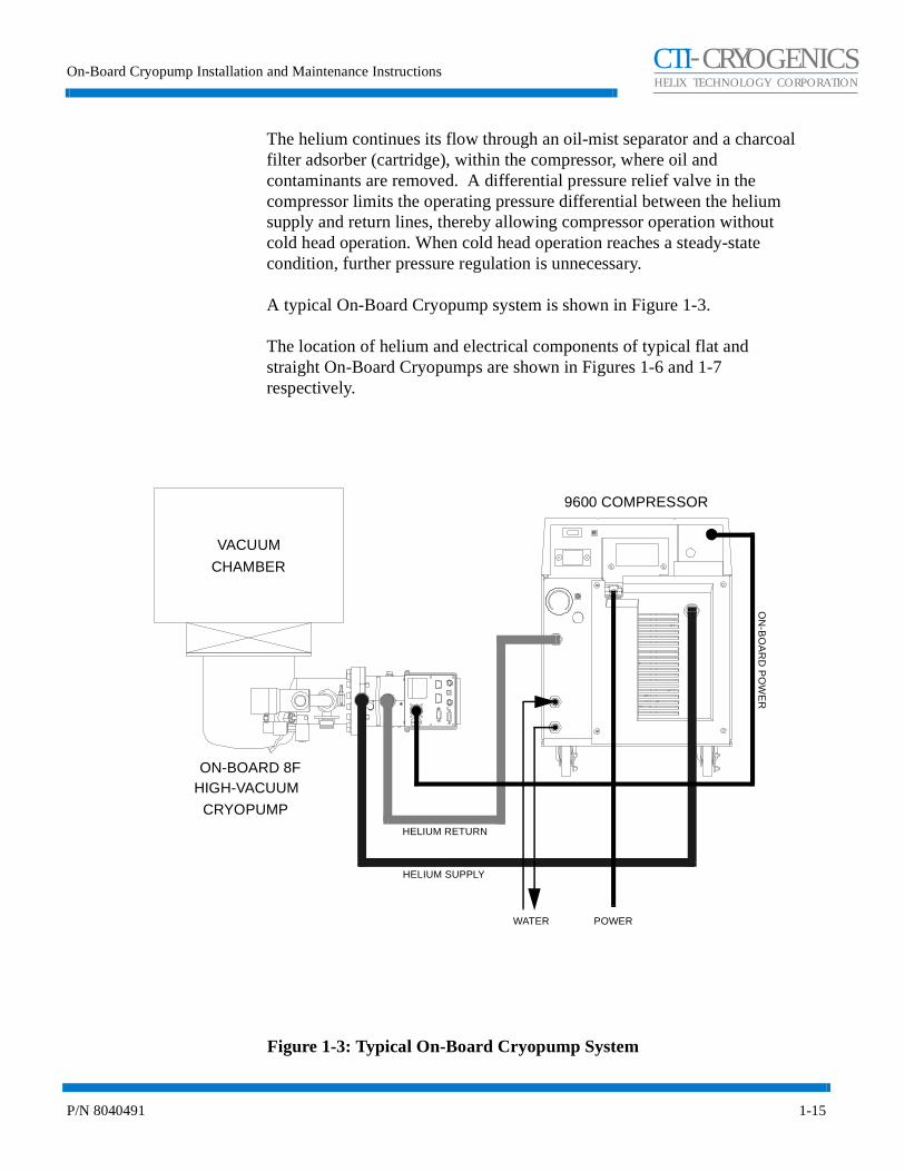
The helium continues its flow through an oil-mist separator and a charcoal filter adsorber (cartridge), within the compressor, where oil and contaminants are removed. A differential pressure relief valve in the compressor limits the operating pressure differential between the helium supply and return lines, thereby allowing compressor operation without cold head operation. When cold head operation reaches a steady-state condition, further pressure regulation is unnecessary.
A typical On-Board Cryopump system is shown in Figure 1-3.
The location of helium and electrical components of typical flat and straight On-Board Cryopumps are shown in Figures 1-6 and 1-7 respectively.
Figure 1-3: Typical On-Board Cryopump System
9600 COMPRESSOR
ON-BOARD 8FHIGH-VACUUM
CRYOPUMP
VACUUM
CHAMBER
ON
-BO
AR
D P
OW
ER
HELIUM SUPPLY
HELIUM RETURN
POWERWATER
On-Board Cryopump Description
P/N 8040491 1-16
CHELIX TECHNOLOGY CORPORATION
-TI CRYOGENICS
Figure 1-4: Cutaway View of a Typical Flat On-Board Cryopump Vessel
80K Array
Mounting
Radiation ShieldSecond Stage
15K Array
Vacuum Vessel
First Stage Heater
Heater
Flange
Cup Shield
On-Board Cryopump Installation and Maintenance Instructions
P/N 8040491 1-17
CHELIX TECHNOLOGY CORPORATION
-TI CRYOGENICS
Figure 1-5: Cutaway View of a Typical Straight On-Board Cryopump Vessel
80K Array
Mounting
Radiation Shield
Second Stage 15K Array
Vacuum VesselFirst Stage Heater
Heater
Flange
Standpipe Filter
First Stage Diode

On-Board Cryopump Description
P/N 8040491 1-18
CHELIX TECHNOLOGY CORPORATION
-TI CRYOGENICS
Figure 1-6: Typical Flat On-Board Cryopump Component Identification
12
3
2
4
5
6 7 8 9 10 11 12 13
LEGEND
1. Auxiliary Thermocouple Gauge Connector2. Network Connectors3. Network Pump Identification Switch4. Power Indicator Lamp5. RS-232 Computer Interface Connector6. Setpoint Relay Connector7. Remote Keypad Connector8. Safety Interlock Screw9. Input Power Connector10. Helium Return Connector11. Helium Supply Connector 12. Pressure Relief Valve13. Purge Gas Connection (10 - 25 psig or 40 - 80 psig) 1/8 NPT14. Rough Pump Connection15. Air Supply Connection (60 - 80 psi, 1/8 NPT)
1514
ON
-BO
AR
D®
FastRegen™
Control
Sputtering

On-Board Cryopump Installation and Maintenance Instructions
P/N 8040491 1-19
CHELIX TECHNOLOGY CORPORATION
-TI CRYOGENICS
Figure 1-7: Typical Straight On-Board Cryopump Component Identification
ON-BOARD®
FastRegen™ Control
Sputtering
2
3
4
5
6 7 6 8 9
12
13
15
16
17
14
LEGEND
1. Thermocouple Gauge2. Rough Pump Connection3. Air Supply Connection (60 - 80 psig 1/8 NPT)4. Purge Gas Connection (10 - 25 psig or 40 - 80 psig 1/8 NPT)5. Auxiliary Thermocouple Gauge Connector6. Network Connectors7. Network Pump Identification Switch8. Power Indicator Lamp9. RS-232 Computer Interface Connector10. Keypad/Display11. Setpoint Relay Connector12. Remote Keypad Connector13. Safety Interlock Screw14. Input Power Connector15. Pressure Relief Valve16. Helium Return Connector17. Helium Supply Connector
1
11
10
On-Board Cryopump Installation and Maintenance Instructions
P/N 8040491 2-1
CHELIX TECHNOLOGY CORPORATION
-TI CRYOGENICS
Section 2 - Installation
Introduction
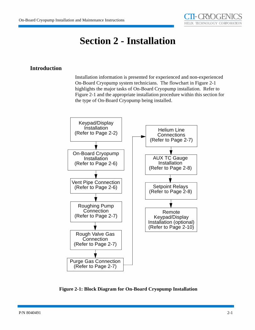
Installation information is presented for experienced and non-experienced On-Board Cryopump system technicians. The flowchart in Figure 2-1 highlights the major tasks of On-Board Cryopump installation. Refer to Figure 2-1 and the appropriate installation procedure within this section for the type of On-Board Cryopump being installed.
Figure 2-1: Block Diagram for On-Board Cryopump Installation
Keypad/DisplayInstallation
(Refer to Page 2-2)
On-Board Cryopump Installation
(Refer to Page 2-6)
Roughing Pump Connection
(Refer to Page 2-7)
Purge Gas Connection(Refer to Page 2-7)
AUX TC GaugeInstallation
(Refer to Page 2-8)
Setpoint Relays(Refer to Page 2-8)
RemoteKeypad/Display
Installation (optional)(Refer to Page 2-10)
Vent Pipe Connection(Refer to Page 2-6)
Helium Line Connections
(Refer to Page 2-7)
Rough Valve Gas Connection
(Refer to Page 2-7)
Installation
2-2 P/N 8040491
CHELIX TECHNOLOGY CORPORATION
-TI CRYOGENICS
Keypad/Display Installation
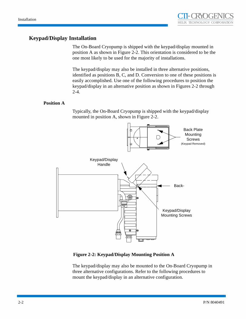
The On-Board Cryopump is shipped with the keypad/display mounted in position A as shown in Figure 2-2. This orientation is considered to be the one most likely to be used for the majority of installations.
The keypad/display may also be installed in three alternative positions, identified as positions B, C, and D. Conversion to one of these positions is easily accomplished. Use one of the following procedures to position the keypad/display in an alternative position as shown in Figures 2-2 through 2-4.
Position A
Typically, the On-Board Cryopump is shipped with the keypad/display mounted in position A, shown in Figure 2-2.
Figure 2-2: Keypad/Display Mounting Position A
The keypad/display may also be mounted to the On-Board Cryopump in three alternative configurations. Refer to the following procedures to mount the keypad/display in an alternative configuration.
Back PlateMounting Screws
(Keypad Removed)
Keypad/Display Handle
Back-
Keypad/Display Mounting Screws

On-Board Cryopump Installation and Maintenance Instructions
P/N 8040491 2-3
CHELIX TECHNOLOGY CORPORATION
-TI CRYOGENICS
Position B
Refer to Figure 2-3 and the following procedure to change keypad/display to position B.
1. Remove the 2 screws, washers, and nuts holding the keypad/display to the back plate.
2. Remove the 2 screws and washers holding the back plate.
3. Rotate the back plate, being careful not to strain the cable, so the keypad/display mounting screw holes are oriented as shown in Figure 2-3.
4. Mount the back plate using the 2 screws and washers removed during step 2.
5. Remount the keypad/display using the 2 screws, washers, and nuts removed in step 1 as shown in Figure 2-3.
Figure 2-3: Keypad/Display Mounting Position B
Back PlateMounting Screws
(Keypad Removed)
Keypad/Display Handle
Backplate
Keypad/Display Mounting Screws
Installation
2-4 P/N 8040491
CHELIX TECHNOLOGY CORPORATION
-TI CRYOGENICS
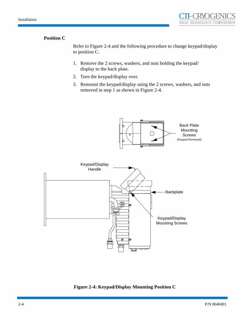
Position C
Refer to Figure 2-4 and the following procedure to change keypad/display to position C.
1. Remove the 2 screws, washers, and nuts holding the keypad/display to the back plate.
2. Turn the keypad/display over.
3. Remount the keypad/display using the 2 screws, washers, and nuts removed in step 1 as shown in Figure 2-4.
Figure 2-4: Keypad/Display Mounting Position C
Back PlateMounting Screws
(Keypad Removed)
Keypad/Display Handle
Backplate
Keypad/Display Mounting Screws

On-Board Cryopump Installation and Maintenance Instructions
P/N 8040491 2-5
CHELIX TECHNOLOGY CORPORATION
-TI CRYOGENICS
Position D
Refer to Figure 2-5 and the following procedure to change keypad/display to position D.
1. Remove the 2 screws, washers, and nuts holding the keypad/display to the back plate.
2. Remove the 2 screws and washers holding the back plate.
3. Rotate the back plate, being careful not to strain the cable, so the keypad/display mounting screw holes are oriented as shown in Figure 2-5.
4. Remount the back plate using the 2 screws and washers removed during step 2.
5. Remount the keypad/display using the 2 screws, washers, and nuts removed in step 1 as shown in Figure 2-5.
Figure 2-5: Keypad/Display Mounting Position D
Back PlateMounting Screws
(Keypad Removed)
Keypad/Display Handle
Backplate
Keypad/Display Mounting Screws
Installation
2-6 P/N 8040491
CHELIX TECHNOLOGY CORPORATION
-TI CRYOGENICS
On-Board Cryopump Installation
The On-Board Cryopump may be installed in any orientation without affecting its performance.
Before mounting the On-Board Cryopump to the vacuum system, a high-vacuum isolation valve (Hi-Vac valve) should be installed between the On-Board Cryopump and the vacuum chamber to isolate the On-Board Cryopump from the chamber during rough pumping, cooldown, and regeneration.
Install the On-Board Cryopump on the vacuum system as follows:
1. Remove the protective cover from the main flange of the On-Board Cryopump.
2. Clean all sealing surfaces and install the O-ring or metal seal gasket as appropriate.
3. Mount the On-Board Cryopump to the Hi-Vac valve or vacuum chamber mounting flange. Be sure all mounting bolts are secure.
Vent Pipe Connection
The On-Board Cryopump pressure relief valve can be vented directly into the room or can be connected to an exhaust system.
WARNINGIf toxic, corrosive, or flammable gases are pumped, a vent pipe must be connected to the On-Board Cryopump relief valve and directed to a safe location.
When connecting a vent pipe to your On-Board Cryopump, the 1.30-inch diameter x 1.38-inch long volume around the relief valve must remain open for proper relief valve operation.
NOTE: A Relief Valve Adapter Exhaust Kit (CTI- CRYOGENICS P/N 8080250K008) is available. Refer to Appendix A and call you local customer support center for more information.
The enhanced On-Board 8F Cryopump installation kit includes a 6 foot (11.83 m) length of 1/2 inch ID (12.7 mm) polytube with associated fittings to allow venting of the cold exhaust as desired in cases where a hard plumbed manifold is not used.

On-Board Cryopump Installation and Maintenance Instructions
P/N 8040491 2-7
CHELIX TECHNOLOGY CORPORATION
-TI CRYOGENICS
CAUTION
For the enhanced On-Board 8F Cryopump, if an exhaust manifold is used, it must have a minimum ID of a 1/2 inch ID (12.7 mm).
Roughing Pump Connection
NOTE: The roughing system must provide 10 cfm (measured at atmosphere and at each On-Board Cryopump) to successfully utilize On-Board FastRegen capability.
Connect your On-Board Cryopump to a roughing pump system using a roughing line with the largest inside diameter possible to minimize the roughing time required during start-up procedures prior to normal operation. The roughing pump should have a blank-off pressure of less than 20 microns.
The roughing pump connects to the On-Board Cryopump roughing valve as shown in Figures 1-6 or 1-7. The valve will accept an ISO NW-25 flange.
1. Install the roughing pump line to the On-Board Cryopump roughing valve port using the clamp provided. Tighten the clamp securely.
Rough Valve Gas Connection
Attach the gas supply line from a 60-80 psig gas supply to the 1/8 NPTF roughing valve fitting. Make sure to attach the gas supply line to the valve fitting that has a filter screen at the attachment connection.
Purge Gas Connection
Connect your purge gas supply line to the purge valve 1/8 NPTF fitting. Adjust the supply pressure to 10 - 25 psig or 40 - 80 psig, depending upon the label on the purge valve, yielding 1-2 cfm.
Helium Line Connections
Make the connections between the On-Board Cryopump and compressor. Refer to Figures 1-6 or 1-7 while making the component interconnections.
1. Remove all dust plugs and caps from the supply and return lines, compressor, and On-Board Cryopump. Check all fittings.

Installation
2-8 P/N 8040491
CHELIX TECHNOLOGY CORPORATION
-TI CRYOGENICS
2. Connect the helium-return line from the gas-return connector on the rear of the compressor to the gas-return connector on the On-Board Cryopump.
3. Connect the helium supply line from the supply connector on the cartridge to the gas-supply connector on the On-Board Cryopump.
4. Attach the supply and return line identification decals (CTI-CRYOGENICS supplied) to their respective connectors.
Verify proper helium supply static pressure as described in the Installation Section of the appropriate Compressor Manual.
Auxiliary (AUX) TC Gauge Installation
You may purchase an auxiliary TC gauge tube, P/N 8112096 and an auxiliary TC gauge cable assembly, P/N 8112098G001.
When used, the auxiliary TC gauge is an extra gauge that can be installed on the User’s equipment to read vacuum between 1 and 1000 microns. It comes with a 1/8 NPT pipe thread. Screw the TC tube into a 1/8 NPTfitting. Attach the auxiliary TC cable to the tube and to the connector on the On-Board module. Refer to Figure 2-6.
NOTE: It may be necessary to zero the auxiliary TC gauge. Refer to the appropriate On-Board Module Programming and Operation Instructions for more information.
Setpoint Relays
When the setpoint relays are used, connection to the relays (R1 and R2) is made via the setpoint relay connector located at the rear of the On-Board controller. If your On-Board Cryopump configuration requires use of the setpoint relays, refer to Figure 2-6 and proceed as follows:
The setpoint relays are two mechanical relays that are incorporated into the On-Board Cryopump for the User’s application. The relays are rated at 1 amp at 25V AC/DC. The relays have both normally-open and normally-closed contacts. Connection to the relays are made through the 9-pin D connector labeled (Relays) on the connector plate on the On-Board Cryopump. Refer to Figure 2-6 for pin identification.
Refer to the appropriate On-Board Module Programming and Operation Instructions for instructions on programming the setpoint relays.
On-Board Cryopump Installation and Maintenance Instructions
P/N 8040491 2-9
CHELIX TECHNOLOGY CORPORATION
-TI CRYOGENICS
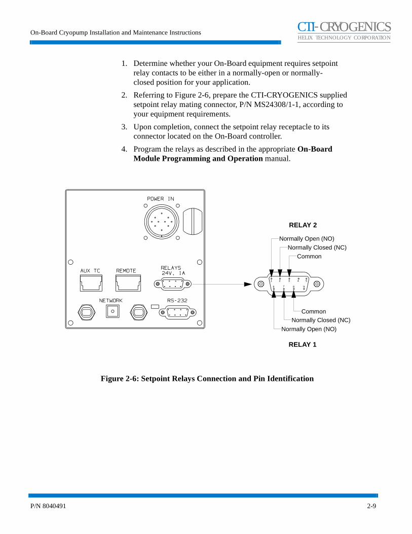
1. Determine whether your On-Board equipment requires setpoint relay contacts to be either in a normally-open or normally-closed position for your application.
2. Referring to Figure 2-6, prepare the CTI-CRYOGENICS supplied setpoint relay mating connector, P/N MS24308/1-1, according to your equipment requirements.
3. Upon completion, connect the setpoint relay receptacle to its connector located on the On-Board controller.
4. Program the relays as described in the appropriate On-Board Module Programming and Operation manual.
Figure 2-6: Setpoint Relays Connection and Pin Identification
Normally Open (NO)
Normally Closed (NC)
Common
CommonNormally Closed (NC)
Normally Open (NO)
1 2 3 4 5
6 7 8 9
RELAY 2
RELAY 1

Installation
2-10 P/N 8040491
CHELIX TECHNOLOGY CORPORATION
-TI CRYOGENICS
Remote Keypad/Display Installation (Optional)
When used, the remote keypad/display is a 19-inch rack-mountable unit. Mount the unit to a rack and then connect it to the REMOTE connector on the On-Board Cryopump Module using the cable supplied with the remote keypad.
The On-Board Cryopump can be operated both from the remote and from the attached keypad/display.
CAUTION
When installing remote keypad cable, care should be taken to route the cable away from power cables and any equipment that may generate excessive EMI conditions.

On-Board Cryopump Installation and Maintenance Instructions
P/N 8040491 3-1
CHELIX TECHNOLOGY CORPORATION
-TI CRYOGENICS
Section 3 - Troubleshooting
Introduction
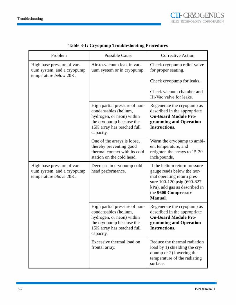
The primary indication of trouble in a vacuum pumping system is a rise in base pressure of your vacuum chamber. A rise in the base pressure may be caused by a leak in the vacuum system, a fault in the On-Board Cryopump, or by saturation of the 15K cryo-adsorbing charcoal array within the On-Board Cryopump (regeneration may be necessary). If the On-Board Cryopump temperature is below 20K it should pump at rated capacity; a high base pressure is usually caused by an air-to-vacuum leak in the system.
If you suspect a leak in your vacuum system, isolate the On-Board Cryopump by closing the Hi-Vac valve and leak check your vacuum chamber. If no leaks are found, a leak may be present below the Hi-Vac valve (cryopump). Leak checking below the Hi-Vac valve should be performed with the On-Board Cryopump shut off and at room temperature. Leak checking while the On-Board Cryopump is operating may mask leaks that are present (due to the ability of the cryopump to pump helium). If no leak is found, refer to the cryopump troubleshooting procedures summarized in Table 3-1.
The problems presented in Table 3-1 are followed by possible causes and corrective actions. The causes and corresponding actions are listed in their order of probability of occurrence.
Maintaining a log of certain parameters during normal operation can be a valuable tool in troubleshooting the cryopump. The log may contain many parameters, however, the following minimum parameters should be included: the cooldown time to 20K, the roughing time to 50µ, the time to base pressure at crossover, the time between regeneration cycles, and the compressor pressure reading.
Technical Inquiries
Please refer to Appendix A of this manual for a complete list of the CTI-CRYOGENICS’ world wide customer support centers.
Troubleshooting
3-2 P/N 8040491
CHELIX TECHNOLOGY CORPORATION
-TI CRYOGENICS
Table 3-1: Cryopump Troubleshooting Procedures
Problem Possible Cause Corrective Action
High base pressure of vac-uum system, and a cryopump temperature below 20K.
Air-to-vacuum leak in vac-uum system or in cryopump.
Check cryopump relief valve for proper seating.
Check cryopump for leaks.
Check vacuum chamber and Hi-Vac valve for leaks.
High partial pressure of non-condensables (helium, hydrogen, or neon) within the cryopump because the 15K array has reached full capacity.
Regenerate the cryopump as described in the appropriate On-Board Module Pro-gramming and Operation Instructions.
One of the arrays is loose, thereby preventing good thermal contact with its cold station on the cold head.
Warm the cryopump to ambi-ent temperature, and retighten the arrays to 15-20 inch/pounds.
High base pressure of vac-uum system, and a cryopump temperature above 20K.
Decrease in cryopump cold head performance.
If the helium return pressure gauge reads below the nor-mal operating return pres-sure 100-120 psig (690-827 kPa), add gas as described in the 9600 Compressor Manual.
High partial pressure of non-condensables (helium, hydrogen, or neon) within the cryopump because the 15K array has reached full capacity.
Regenerate the cryopump as described in the appropriate On-Board Module Pro-gramming and Operation Instructions.
Excessive thermal load on frontal array.
Reduce the thermal radiation load by 1) shielding the cry-opump or 2) lowering the temperature of the radiating surface.

On-Board Cryopump Installation and Maintenance Instructions
P/N 8040491 3-3
CHELIX TECHNOLOGY CORPORATION
-TI CRYOGENICS
Table 3-1: Troubleshooting Procedures (continued)
Problem Possible Cause Corrective Action
Cryopump fails to cool down to the required operating tem-perature or takes too long to reach that temperature (20K).
Low helium supply pressure. Add gas as described in the 9600 Compressor Manual.
Compressor problems. Refer to the 9600 Compres-sor Manual.
Leak in vacuum system or cryopump.
Check the cryopump relief valve for proper seating.
Check cryopump for leaks.
Check vacuum system for leaks.
Incomplete regeneration may not have fully cleaned the adsorbing array. Partial pres-sures of non-condensables (hydrogen, neon or helium) may remain.
Regenerate the cryopump as described in the appropriate On-Board Module Pro-gramming and Operation Instructions.
No display. No power to On-Board cry-opump.
Check electrical connec-tions; be sure the power switch at the compressor con-troller is turned on. Check fuses. If power is turned on, try turning it off and on to reboot the electronics. Change electronics module.
Display does not update, and/or keys do not function.
Electronics has locked up. Try to reboot the system by turning the On-Board power switch located at the com-pressor controller off and on. Replace the On-Board elec-tronic module.
Rough valve clicks but does not open and close.
Too little or no air pressure to drive valve.
Increase air pressure to 60 psig minimum, 80 psig maxi-mum.

On-Board Cryopump Installation and Maintenance Instructions
P/N 8040491 4-1
CHELIX TECHNOLOGY CORPORATION
-TI CRYOGENICS
Section 4 - Maintenance
Helium Circuit Decontamination
The information in Section 4 will guide you through the process of removing gaseous contamination from an On-Board Cryopump helium circuit by freezing the contaminant in the coldhead of the On-Board Cryopump. A contaminated helium circuit will cause the On-Board Cryopump to operate in a noisy manner, typically referred to as ratcheting, which degrades On-Board Cryopump performance.
Separate decontamination of the compressor is only required if the compressor has been opened to atmosphere or the helium pressure in the compressor has dropped to zero.
Three methods of decontamination are described in Table 4-1 and on the following pages. These methods all have isolating gaseous contamination in common by freezing them in one or more cold On-Board Cryopumps. The method to be used will most likely be determined by the amount of time available for the decontamination.
Table 4-1: Methods of Decontamination
MethodStarting
ConditionEstimated Time
Effectiveness of Decontamination
1. Cooldown and Sequential decon-tamination of all On-Board Cryopumps
Requires all On-Board Cryopumps to be cold.
After all On-Board Cryopumps are cold, 45 minutes to decon-taminate the first On-Board Cry-opump. 30 minutes for each additional On-Board Cryopump.
Maximum
2. Decontamination of only cold On-Board Cryopumps
Only one On-Board Cryopump needs to be cold.
45 minutes to decontaminate the first cold On-Board Cryopump. 30 minutes for each additional cold On-Board Cryopump.
Acceptable
3. Simultaneous decontamination of all On-Board Cryopumps using helium manifold
Only one On-Board Cryopump needs to be cold.
45 minutes Acceptable(may need to be
repeated in several months).
Maintenance
4-2 P/N 8040491
CHELIX TECHNOLOGY CORPORATION
-TI CRYOGENICS
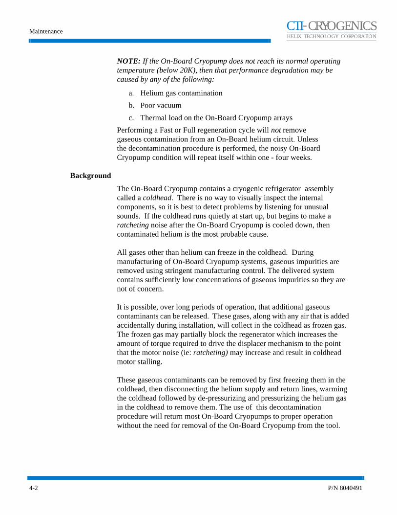
NOTE: If the On-Board Cryopump does not reach its normal operating temperature (below 20K), then that performance degradation may be caused by any of the following:
a. Helium gas contamination
b. Poor vacuum
c. Thermal load on the On-Board Cryopump arrays
Performing a Fast or Full regeneration cycle will not remove gaseous contamination from an On-Board helium circuit. Unless the decontamination procedure is performed, the noisy On-Board Cryopump condition will repeat itself within one - four weeks.
Background
The On-Board Cryopump contains a cryogenic refrigerator assembly called a coldhead. There is no way to visually inspect the internal components, so it is best to detect problems by listening for unusual sounds. If the coldhead runs quietly at start up, but begins to make a ratcheting noise after the On-Board Cryopump is cooled down, then contaminated helium is the most probable cause.
All gases other than helium can freeze in the coldhead. During manufacturing of On-Board Cryopump systems, gaseous impurities are removed using stringent manufacturing control. The delivered system contains sufficiently low concentrations of gaseous impurities so they are not of concern.
It is possible, over long periods of operation, that additional gaseous contaminants can be released. These gases, along with any air that is added accidentally during installation, will collect in the coldhead as frozen gas. The frozen gas may partially block the regenerator which increases the amount of torque required to drive the displacer mechanism to the point that the motor noise (ie: ratcheting) may increase and result in coldhead motor stalling.
These gaseous contaminants can be removed by first freezing them in the coldhead, then disconnecting the helium supply and return lines, warming the coldhead followed by de-pressurizing and pressurizing the helium gas in the coldhead to remove them. The use of this decontamination procedure will return most On-Board Cryopumps to proper operation without the need for removal of the On-Board Cryopump from the tool.

On-Board Cryopump Installation and Maintenance Instructions
P/N 8040491 4-3
CHELIX TECHNOLOGY CORPORATION
-TI CRYOGENICS
NOTE: It is strongly recommended that this procedure be performed as soon as possible after the ratcheting noise appears to minimize mechanical loading on the On-Board Cryopump drive mechanism.
NOTE: If any additional help is needed, refer to Appendix A in this manual for the location of the nearest CTI-CRYOGENICS Customer Support Center.
Equipment/Tools Requirements
The following tools and equipment must be available to perform this decontamination procedure. If you do not have this equipment, refer to Appendix A and call your local Customer Support Center to order the equipment needed.
NOTE: For best results, CTI-CRYOGENICS suggests the use of a dedicated helium bottle, regulator and charge line which are never separated.
Table 4-2: Decontamination Tools and Equipment
CTI-CRYOGENICS Part Number
Description Quantity
8080250K003 Maintenance Manifold Kit 1
7021002P001 Charging Hose 1
8043079G060 5 Ft. Flexlines(or longer)
2
- Ultra Pure Helium (99.999%) -
571716 1.0 Inch Self Sealing Coupling Wrench 1
571717 1 1/8 Inch Self Sealing Coupling Wrench 1
571718 1 3/16 Inch Self Sealing Coupling Wrench 1
8080015K001 Keypad/display 1
8031403 0-400/0-3000 psig Regulator 1

Maintenance
4-4 P/N 8040491
CHELIX TECHNOLOGY CORPORATION
-TI CRYOGENICS
Figure 4-1: Decontamination Flowchart
Cool On-Board Cryopump(s) until
temperature is stable for a minimum of 30 minutes.
Purge regulator, helium charging line, and
maintenance manifold with 99.999% pure helium.
Disconnect helium SUPPLY line at coldheads
on same manifold.
Immediately disconnect helium RETURN line at coldheads on same
manifold.
Immediatelyshut down the On-Board
Cryopump(s).
Warm the On-Board Cryopump(s) to
300K.
Shut downcompressor
Slowly open ball valve on maintenance manifold and depressurize the coldhead
to 30 - 50 psig.
Back-fill coldhead to the correct static helium
pressure and close Hoke valve.
Have you pressurized and depressurized
5 times?
Yes
No
Go to Page 4-5
Slowly open ball valve on maintenance manifold and depressurize the coldhead
to 30 - 50 psig.
Back-fill coldhead to the correct static helium
pressure.
Step1
Steps2,3,4
Step5
Step6
Steps7
Step8
Step9
Step11
Step12a
Step12b
Step12c
Step12d
Connect two 5 foot flexlines to the
maintenance manifold and the first On-Board Cryopump to be decontaminated.
Step10
On-Board Cryopump Installation and Maintenance Instructions
P/N 8040491 4-5
CHELIX TECHNOLOGY CORPORATION
-TI CRYOGENICS
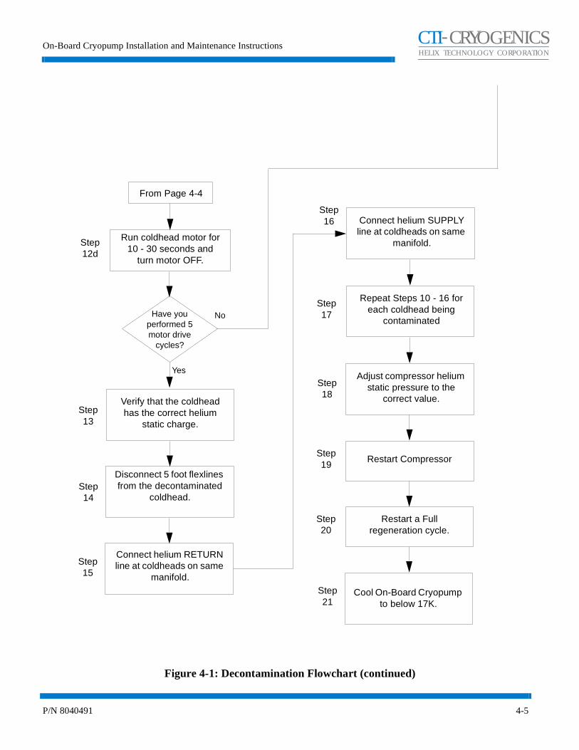
Figure 4-1: Decontamination Flowchart (continued)
Run coldhead motor for 10 - 30 seconds and
turn motor OFF.
Have you performed 5 motor drive
cycles?
Yes
No
Verify that the coldhead has the correct helium
static charge.
Disconnect 5 foot flexlines from the decontaminated
coldhead.
Connect helium SUPPLY line at coldheads on same
manifold.
Connect helium RETURN line at coldheads on same
manifold.
Adjust compressor helium static pressure to the
correct value.
Restart a Full regeneration cycle.
Cool On-Board Cryopump to below 17K.
Repeat Steps 10 - 16 for each coldhead being
contaminated
Step12d
Step13
Step14
Step15
Step16
Step18
Step17
Step20
Step21
From Page 4-4
Restart CompressorStep19

Maintenance
4-6 P/N 8040491
CHELIX TECHNOLOGY CORPORATION
-TI CRYOGENICS
Method 1 - Decontaminate all On-Board Cryopumps
This procedure removes gaseous contamination from the helium circuit by cooling each On-Board Cryopump so the gaseous contamination is frozen in the coldhead. Each On-Board Cryopump is then decontaminated in sequence. This procedure is outlined in Figure 4-1.
WARNINGHigh helium gas pressure may be present within high vacuum pump systems and can cause severe injury from propelled particles or parts.
1. All On-Board Cryopumps on the same manifold should have been running with second stage below 25K for at least 30 minutes. If not, then cool the remaining On-Board Cryopumps down and run for 30 minutes minimum after reaching 25K to trap contaminants in the coldhead. Continue with Step 2 even if any pump does not cool below 25K (its performance may already be affected by contamination). Close the high vacuum valves to isolate the On-Board Cryopumps from the vacuum chamber.
After Step 1 has been completed, all of the coldheads have been cooled and the contaminant gases frozen in the coldhead.
2. Attach a regulator (0-400/0-3000 psig) and charging line to a helium bottle (99.999% pure). DO NOT OPEN THE BOTTLE VALVE AT THIS TIME.
3. Purge the regulator and charging line as described in Steps a through d below. Use only 99.999% helium gas.
a. Open the regulator a small amount by turning the adjusting knob clockwise until it contacts the diaphragm, turn the adjusting knob so that the regulator is barely open.
b. Slowly open the bottle valve, and purge the regulator and line for 10 to 15 seconds. Keep the helium flowing to prevent re-contamination.
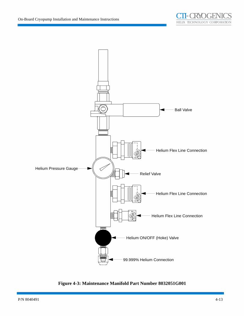
c. Loosely connect the charge line to the closed Hoke valve on the maintenance manifold. Refer to Figure 4-3.
d. Continue to purge the charge line for 30 seconds, and tighten the charge line flare fitting onto the Hoke valve while the helium is flowing.

On-Board Cryopump Installation and Maintenance Instructions
P/N 8040491 4-7
CHELIX TECHNOLOGY CORPORATION
-TI CRYOGENICS
4. Open the ball valve using the extended handle. Open the Hoke valve. Purge the manifold for 30 seconds, close the ball valve, then close the Hoke valve.
Steps 2 - 4 are required to ensure that the regulator, charging line and the maintenance manifold will be purged of air and that the air trapped in the regulator will not diffuse back into the helium bottle. For best results, CTI-CRYOGENICS suggests the use of a dedicated helium bottle, regulator and charge line which are never separated.
Once Step 4 has been completed, all of the coldheads have been cooled and the gaseous contaminant frozen in the coldhead. The maintenance manifold has also been connected to the helium bottle and filled with clean helium.
NOTE: The helium SUPPLY line should be disconnected first to prevent the crosshead relief valve from opening.
5. While each On-Board Cryopump is still operating, disconnect the helium SUPPLY line at all of the coldheads on the same manifold. The On-Board Cryopump helium supply line is shown in Figure 4-2.
CAUTION
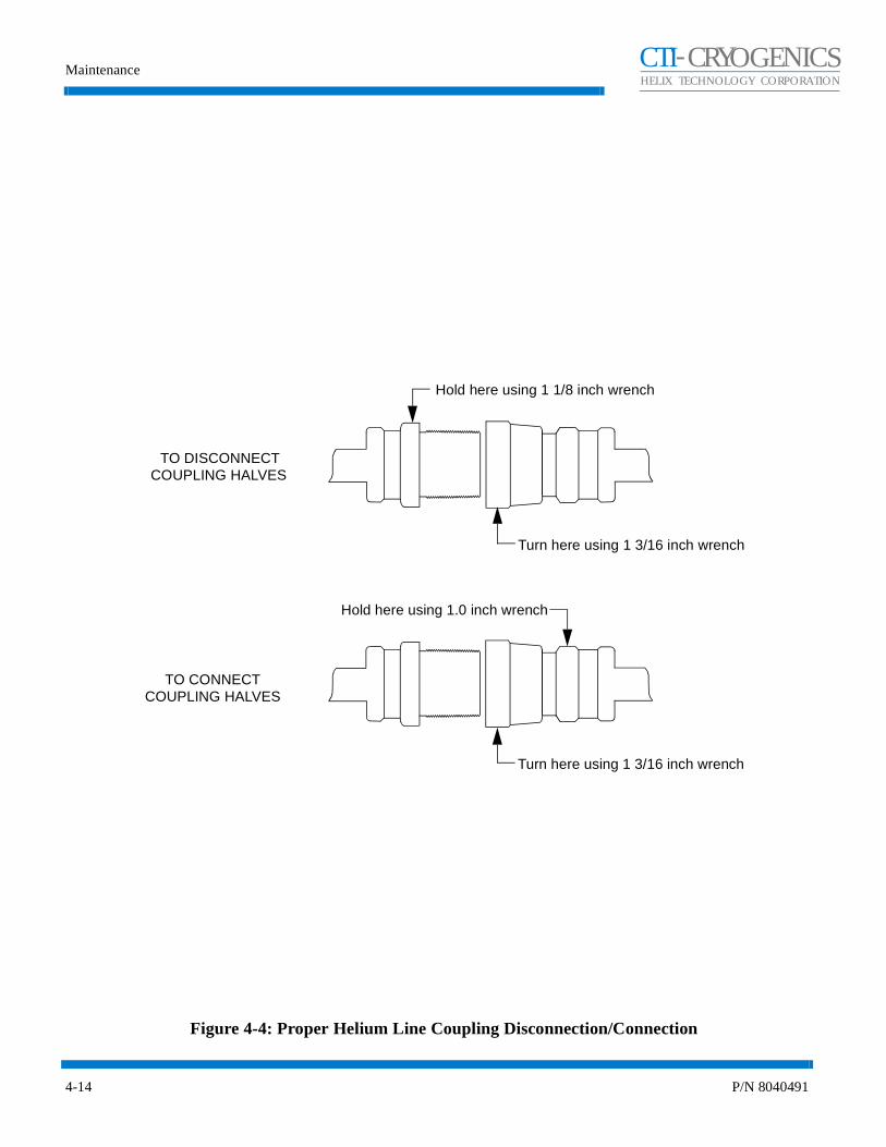
Be sure to use two wrenches to ensure that the self sealing coupling adapter does not back out during disassembly. Disconnect the helium supply line. Refer to Figure 4-4.
6. Immediately after Step 5, and while each On-Board Cryopump is still operating, disconnect the helium RETURN line at all of the coldheads on the same manifold. The On-Board Cryopump helium return line is shown in Figure 4-2.

Maintenance
4-8 P/N 8040491
CHELIX TECHNOLOGY CORPORATION
-TI CRYOGENICS
Figure 4-2: On-Board Cryopump Helium Supply and Return Lines
7. Immediately after Step 7, shut down all of the On-Board Cryopumps as described in the appropriate On-Board Module Programming and Operation Instructions manual.
8. Warm the On-Board Cryopumps to 300K as follows:
a. Regenerate each On-Board Cryopump to be decontaminated by pressing the REGEN button, followed by 1 then 2 on the Network Terminal keypad.
b. When the pumps reach 300K, discontinue the regeneration cycle by pressing REGEN and 0. Repeat this process on each pump.
After Step 8 has been completed, all of the coldheads have been cooled and the contaminant gases frozen in the coldhead. Helium gas lines have been disconnected at the coldheads, and the coldheads warmed up to 300K. The next step is to remove the contaminant from each coldhead in sequence.
9. Shut down the compressor.
10. Connect the two helium flexlines to the maintenance manifold and the coldhead of the first On-Board Cryopump to be decontaminated.
CAUTIONBe sure to use two wrenches to ensure that the self sealing coupling adapter does not back out during disassembly. Disconnect the helium supply line. Refer to Figure 4-4.
Helium Supply LineHelium Return Line
On-Board Cryopump Installation and Maintenance Instructions
P/N 8040491 4-9
CHELIX TECHNOLOGY CORPORATION
-TI CRYOGENICS
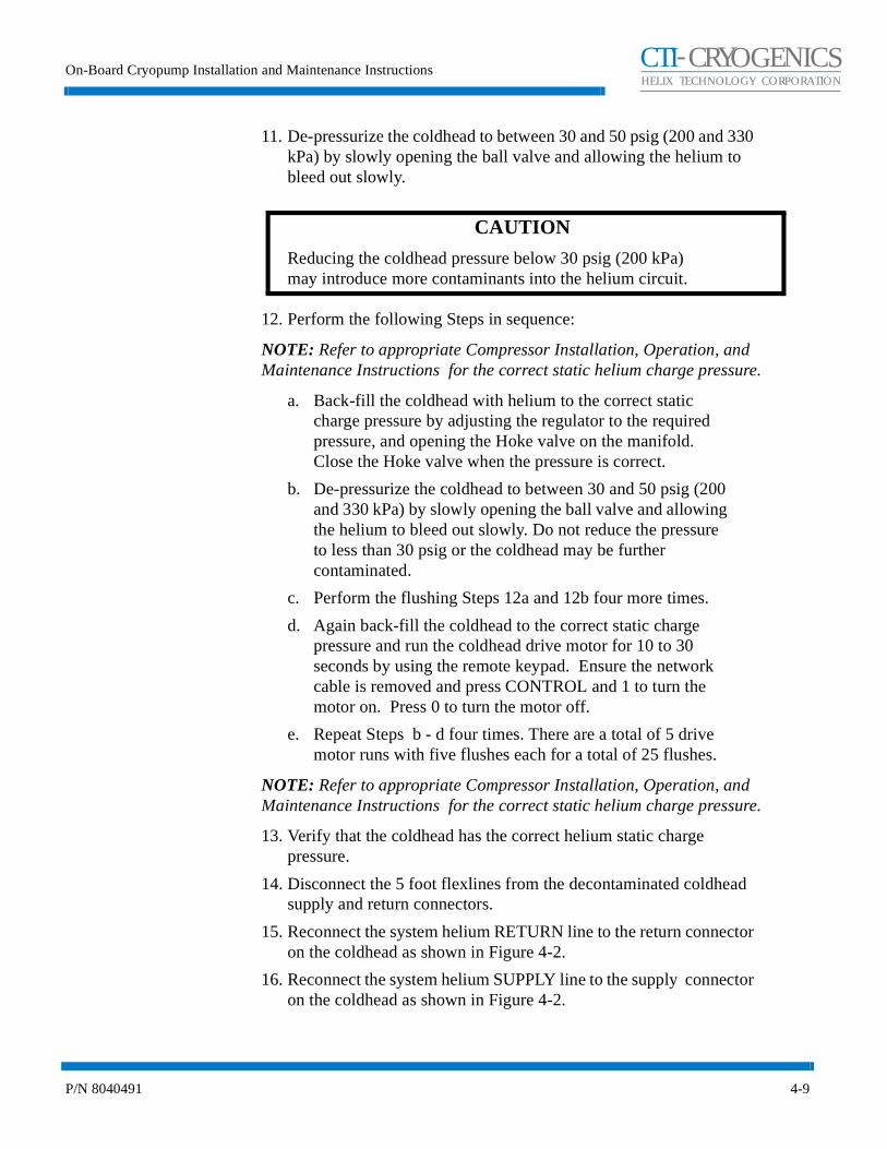
11. De-pressurize the coldhead to between 30 and 50 psig (200 and 330 kPa) by slowly opening the ball valve and allowing the helium to bleed out slowly.
CAUTION
Reducing the coldhead pressure below 30 psig (200 kPa) may introduce more contaminants into the helium circuit.
12. Perform the following Steps in sequence:
NOTE: Refer to appropriate Compressor Installation, Operation, and Maintenance Instructions for the correct static helium charge pressure.
a. Back-fill the coldhead with helium to the correct static charge pressure by adjusting the regulator to the required pressure, and opening the Hoke valve on the manifold. Close the Hoke valve when the pressure is correct.
b. De-pressurize the coldhead to between 30 and 50 psig (200 and 330 kPa) by slowly opening the ball valve and allowing the helium to bleed out slowly. Do not reduce the pressure to less than 30 psig or the coldhead may be further contaminated.
c. Perform the flushing Steps 12a and 12b four more times.
d. Again back-fill the coldhead to the correct static charge pressure and run the coldhead drive motor for 10 to 30 seconds by using the remote keypad. Ensure the network cable is removed and press CONTROL and 1 to turn the motor on. Press 0 to turn the motor off.
e. Repeat Steps b - d four times. There are a total of 5 drive motor runs with five flushes each for a total of 25 flushes.
NOTE: Refer to appropriate Compressor Installation, Operation, and Maintenance Instructions for the correct static helium charge pressure.
13. Verify that the coldhead has the correct helium static charge pressure.
14. Disconnect the 5 foot flexlines from the decontaminated coldhead supply and return connectors.
15. Reconnect the system helium RETURN line to the return connector on the coldhead as shown in Figure 4-2.
16. Reconnect the system helium SUPPLY line to the supply connector on the coldhead as shown in Figure 4-2.

Maintenance
4-10 P/N 8040491
CHELIX TECHNOLOGY CORPORATION
-TI CRYOGENICS
Once Step 16 has been completed, the decontamination of the first On-Board Cryopump is completed and charged to the correct pressure with clean helium. The remaining coldheads need to be decontaminated.
17. Repeat Steps 10 - 16 for each coldhead being decontaminated.
18. Once Step 17 has been completed, the On-Board Cryopumps are ready to be cooled down. Adjust the compressor pressure to the correct charge pressure.
NOTE: Refer to the appropriate Compressor Installation, Operation, and Maintenance Instructions for the correct static helium charge pressure value and adjustment procedure.
NOTE: The charging adapter can be inserted into any helium line at the tool to simplify the final adjustment of system pressure. It should be removed after final pressure adjustment.
19. Restart the compressor.
20. Start a Full Regeneration cycle on all the On-Board Cryopumps to prepare the vacuum side of the On-Board Cryopump.
21. Allow the On-Board Cryopumps cryopumps to cool to below 17K.
If ratcheting in the On-Board Cryopump reappears, refer to Appendix A and call your nearest CTI-CRYOGENICS Customer Support Center for additional technical assistance.
Decontamination Alternatives
Method #1 Decontaminate All Cryopumps
The preceding procedure is the most effective method to remove gaseous contaminants from the helium circuit. All On-Board Cryopumps were first cooled down and the contaminant frozen. Each On-Board Cryopump was decontaminated in sequence.
All On-Board Cryopumps that are cold must be decontaminated. If they are cold and not decontaminated, then gases frozen in these On-Board Cryopumps will re-contaminate the helium gas when they are warmed up.
Method # 2 Decontamination of Only Cold Cryopumps
If time is critical, then an alternate method of decontamination, using Method 1 as a basis may be used. This procedure will also remove gaseous contaminant in the system.
If certain On-Board Cryopumps are warm in Step 1 then they can remain at room temperature (i.e. over 290K). With the compressor on and cold

On-Board Cryopump Installation and Maintenance Instructions
P/N 8040491 4-11
CHELIX TECHNOLOGY CORPORATION
-TI CRYOGENICS
On-Board Cryopumps left on, run these “warm” On-Board Cryopumps for 5 minutes. Running these “warm” On-Board Cryopumps for a short time will move any concentrated contaminant out of these coldheads into the compressor. The contaminants will then be carried to the cold On-Board Cryopumps where they will be frozen.
In this method, the following Steps replace the corresponding Steps in Method 1:
Step 1 - Method #2
Any On-Board Cryopumps on the same manifold which are running should have been running below 25K for at least 30 minutes. Any pumps warmer than 290K should be kept warm. Continue with Step 2 even if any pump does not cool below 25K (its performance may already be affected by contamination). Close the high vacuum valves to isolate the On-Board Cryopumps from the vacuum chamber.
Step 17 - Method #2
Repeat Steps 10 - 16 for each On-Board Cryopump which is not above 290K.
Method # 3 Grouped Decontamination using Manifold
The time required to decontaminate each On-Board Cryopump in Method #1 after it is cooled and warmed up is about 30 minutes. If time is not available to decontaminate each On-Board Cryopump in sequence, then the alternate is to decontaminate all On-Board Cryopumps together, i.e.: Grouped Decontamination. At least one of the On-Board Cryopumps must be cold. The decontamination is performed from the compressor side of the common supply and return manifolds.
In this method the following Steps replace the previous Steps:
Step 5 - Method #3
While each On-Board Cryopump is still operating, disconnect the helium SUPPLY line at the compressor side of the common supply manifold at the tool.

Maintenance
4-12 P/N 8040491
CHELIX TECHNOLOGY CORPORATION
-TI CRYOGENICS
Step 6 - Method #3
While each On-Board Cryopump is still operating, disconnect the helium RETURN line at the compressor side of the common supply manifold at the tool.
Step 10- Method #3
Verify that the compressor is off. Connect the two 5 foot helium flexlines to the maintenance manifold and the compressor side of the common supply and return manifold.
CAUTION
Be sure to use two wrenches to ensure that the self sealing coupling adapter does not back out during disassembly. Disconnect the helium supply line. Refer to Figure 4-4.
Steps 11 - 16 - Method #3
All connections are to the manifold, not the individual coldheads. All coldhead drive motors are to be run for 10 to 30 seconds using the remote keypads per Step 12d. At the end of Step 16, all of the On-Board Cryopumps are decontaminated.
On-Board Cryopump Installation and Maintenance Instructions
P/N 8040491 4-13
CHELIX TECHNOLOGY CORPORATION
-TI CRYOGENICS
Figure 4-3: Maintenance Manifold Part Number 8032051G001
Helium Flex Line Connection
Helium Pressure Gauge
Ball Valve
99.999% Helium Connection
Helium ON/OFF (Hoke) Valve
Relief Valve
Helium Flex Line Connection
Helium Flex Line Connection
Maintenance
4-14 P/N 8040491
CHELIX TECHNOLOGY CORPORATION
-TI CRYOGENICS
Figure 4-4: Proper Helium Line Coupling Disconnection/Connection
TO CONNECT
Hold here using 1.0 inch wrench
Turn here using 1 3/16 inch wrench
Hold here using 1 1/8 inch wrench
Turn here using 1 3/16 inch wrench
COUPLING HALVES
TO DISCONNECT COUPLING HALVES

On-Board Cryopump Installation and Maintenance Instructions
P/N 8040491 4-15
CHELIX TECHNOLOGY CORPORATION
-TI CRYOGENICS
On-Board Cryopump Cleaning
WARNINGIf the On-Board Cryopump has been used to pump toxic or dangerous materials, you must take adequate precautions to safeguard personnel.
Cleaning the arrays or other interior surfaces of the On-Board Cryopump vacuum vessel is seldom required because dust buildup does not affect performance, and the special copper alloy cryo-condensing arrays are nickel plated for corrosion resistance.
If you wish to clean the arrays and other interior surfaces, follow the procedures below.
1. Confirm that an adequate supply of indium gasket material, P/N 7100001G006, is available to replace gaskets inadvertently damaged during disassembly.
2. Carefully disassemble the components in the vacuum vessel, including the arrays and radiation shield, to avoid damage to the indium gaskets.
3. Clean the interior surface of the vacuum vessel, the 80K condensing array, and the 80K radiation shield as follows:
a. Wash each item in strong soap or detergent solution and hot water.
b. Rinse the items in clean hot water.
c. Air or oven dry all items at 150° F (66° C) maximum before reinstalling into the On-Board Cryopump.
CAUTION
Do not clean the 15K cryo-adsorbing array, because you may severely contaminate the adsorbent in the cleaning process.
4. Wearing lint-free gloves, reassemble the On-Board Cryopump. Replace any indium gasket damaged during disassembly.
Appendix A - Customer Support Centers
A-1
CHELIX TECHNOLOGY CORPORATION
-TI CRYOGENICS
Appendix A - Customer Support Centers
Introduction
Refer to Table A-1 for the nearest Customer Support Center for technical assistance or service. North American customers may call 800-FOR-GUTS (800-367-4887) 24 hours a day, seven days a week. All other customers must call their local Customer Support Center.
Please have the following information available when calling so that we may assist you:
• Product Part Number
• Product Serial Number
• Product Application
• Specific Problem Area
• Hours of Operation
• Equipment Type
• Vacuum System Brand/Model/Date of Manufacture
For your convenience, you may also e-mail us at: [email protected]
Visit us at our corporate website: www.helixtechnology.com
Appendix A - Customer Support Centers
A-2
CHELIX TECHNOLOGY CORPORATION
-TI CRYOGENICS
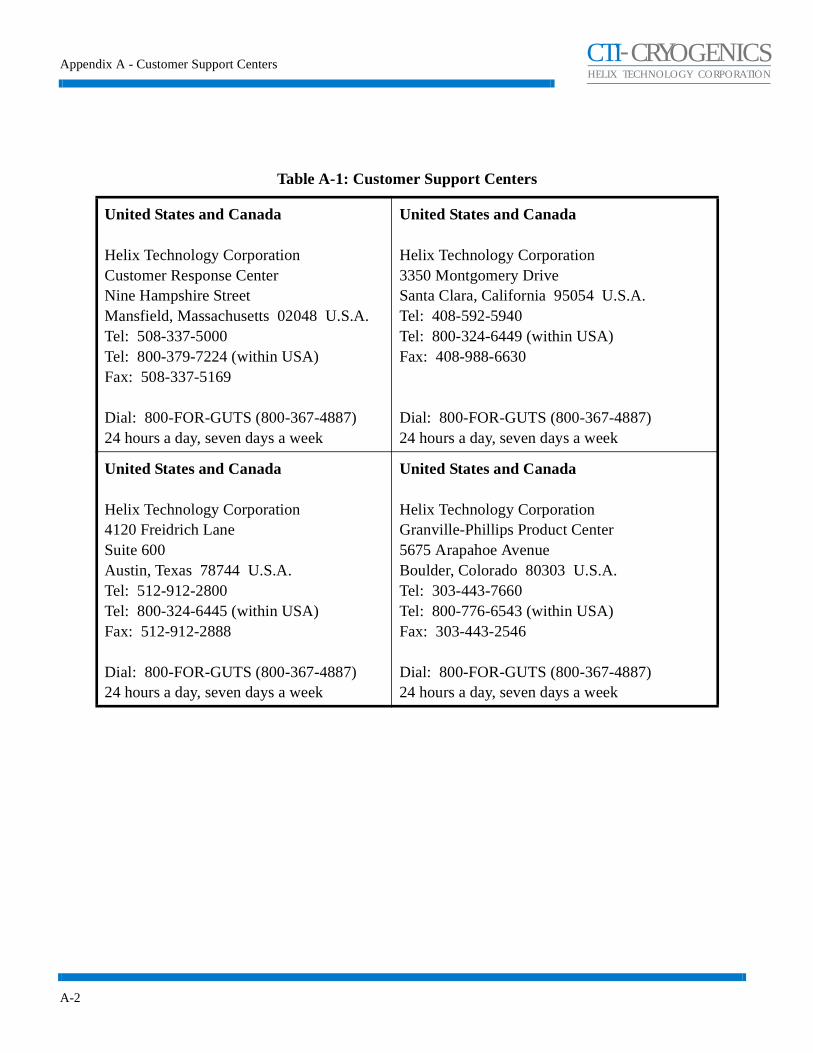
Table A-1: Customer Support Centers
United States and Canada
Helix Technology CorporationCustomer Response CenterNine Hampshire StreetMansfield, Massachusetts 02048 U.S.A.Tel: 508-337-5000Tel: 800-379-7224 (within USA)Fax: 508-337-5169
Dial: 800-FOR-GUTS (800-367-4887)24 hours a day, seven days a week
United States and Canada
Helix Technology Corporation3350 Montgomery DriveSanta Clara, California 95054 U.S.A.Tel: 408-592-5940Tel: 800-324-6449 (within USA)Fax: 408-988-6630
Dial: 800-FOR-GUTS (800-367-4887)24 hours a day, seven days a week
United States and Canada
Helix Technology Corporation4120 Freidrich LaneSuite 600Austin, Texas 78744 U.S.A.Tel: 512-912-2800Tel: 800-324-6445 (within USA)Fax: 512-912-2888
Dial: 800-FOR-GUTS (800-367-4887)24 hours a day, seven days a week
United States and Canada
Helix Technology CorporationGranville-Phillips Product Center5675 Arapahoe AvenueBoulder, Colorado 80303 U.S.A.Tel: 303-443-7660Tel: 800-776-6543 (within USA)Fax: 303-443-2546
Dial: 800-FOR-GUTS (800-367-4887)24 hours a day, seven days a week

Appendix A - Customer Support Centers
A-3
CHELIX TECHNOLOGY CORPORATION
-TI CRYOGENICS
Germany, Italy, Denmark, Switzerland, Holland, Norway, The Netherlands
Helix Technology CorporationHaasstrasse 15D-64293 DarmstadtGermany Tel: +(49) 6151-959-55Fax: +(49) 6151-959-57
Dial: +(49) 6151-959-5524 hours a day, seven days a week
France, Spain, Portugal, Greece
Helix TechnologyDomaine Technologique de Saclay4, rue Rene Razel, Bât ApolloF-91892 Orsay CedexFranceTel: +(33) 1-6935-2600Fax: +(33) 1-6985-3725
Dial: +(33) 1-6935-260024 hours a day, seven days a week
United Kingdom, Ireland, Sweden, N. Ireland
Helix Technology CorporationFleming RoadKirkton CampusLivingston. West LothianScotland EH54 7BNTel: +(44) 1-506-460017Fax: +(44) 1-506-411122
Dial: +(44) 1-506-46001724 hours a day, seven days a week
Japan
Helix Technology CorporationQueens Tower A 14F3-1, Minatomirai 2-chomeNishi-ku, YokohamaJapan 220-6014Tel: +(81) 45-682-5470Fax: +(81) 45-682-5475
Dial: +(81) 45-682-547024 hours a day, seven days a week
Table A-1: Customer Support Centers (Continued)
Appendix A - Customer Support Centers
A-4
CHELIX TECHNOLOGY CORPORATION
-TI CRYOGENICS
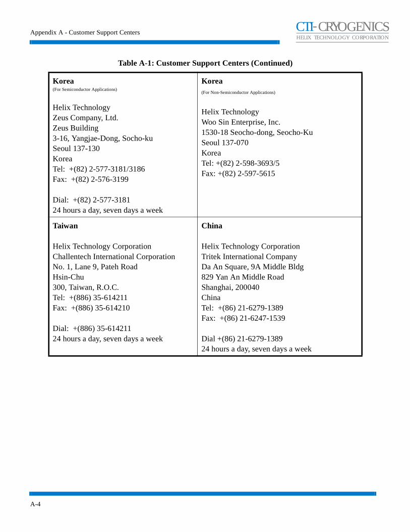
Korea(For Semiconductor Applications)
Helix TechnologyZeus Company, Ltd.Zeus Building3-16, Yangjae-Dong, Socho-kuSeoul 137-130KoreaTel: +(82) 2-577-3181/3186Fax: +(82) 2-576-3199
Dial: +(82) 2-577-318124 hours a day, seven days a week
Korea(For Non-Semiconductor Applications)
Helix TechnologyWoo Sin Enterprise, Inc.1530-18 Seocho-dong, Seocho-KuSeoul 137-070KoreaTel: +(82) 2-598-3693/5Fax: +(82) 2-597-5615
Taiwan
Helix Technology CorporationChallentech International CorporationNo. 1, Lane 9, Pateh RoadHsin-Chu300, Taiwan, R.O.C.Tel: +(886) 35-614211Fax: +(886) 35-614210
Dial: +(886) 35-61421124 hours a day, seven days a week
China
Helix Technology CorporationTritek International CompanyDa An Square, 9A Middle Bldg829 Yan An Middle RoadShanghai, 200040ChinaTel: +(86) 21-6279-1389Fax: +(86) 21-6247-1539
Dial +(86) 21-6279-138924 hours a day, seven days a week
Table A-1: Customer Support Centers (Continued)

Appendix A - Customer Support Centers
A-5
CHELIX TECHNOLOGY CORPORATION
-TI CRYOGENICS
Australia, New Zealand, Tasmania
Helix Technology CorporationCTI-Cryogenics ProductsAVT Services Pte. Ltd. Unit 1, 12 Pioneer AvenueThornleigh NSW 2120 Sydney, Australia Tel: +(612) 9-4810748Fax: +(612) 9-4810910
Dial: +(612) 9-481074824 hours a day, seven days a week
Australia, New Zealand, Tasmania
Helix Technology CorporationGranville-Phillips ProductsStanton Scientific2/6 Jonson St. Byron Bay, NSW 2481 Australia Tel: +(61) 66-856-902 Fax: +(61) 66-858-530
Singapore, Malaysia, Philippines, Indonesia
Helix Technology CorporationAPP Systems Services Pte Ltd.2 Corporation Road#06-14 Corporation PlaceSingapore 2261 Tel: +(65) 268-2024Fax: +(65) 268-6621
Dial: +(65) 268-202424 hours a day, seven days a week
India
Helix Technology CorporationCTI-Cryogenics ProductsGoodwill Cryogenics Enterprise213 Nirman, Sec. 17, VashiNew Bombay, 400703IndiaTel: +(91) 22-7632906Fax: +(91) 22-7822769
Dial: +(91) 22-763290624 hours a day, seven days a week
Table A-1: Customer Support Centers (Continued)

Appendix A - Customer Support Centers
A-6
CHELIX TECHNOLOGY CORPORATION
-TI CRYOGENICS
India
Helix Technology CorporationGranville-Phillips ProductsAshwini Enterprises C-2/13/03, Sector-16, Vashi New Bombay 400 705 India Tel: +(91) 22-766 1107 Fax: +(91) 22-766 2631
Israel
Helix Technology CorporationCTI-Cryogenics ProductsVacuum System & Technology Ltd.P.O. Box 4137Petach Tikva 49130IsraelTel: +(972) 3-9247710Fax: +(972) 3-9247711
Dial: +(972) 3-924771024 hours a day, seven days a week
Israel
Helix Technology CorporationGranville-Phillips ProductsEl-Tan TechnologiesP.O. Box 1020Hod-Hasharon 45110IsraelTel: +(972) 9-740-5551Fax: +(972) 9-740-6690
Table A-1: Customer Support Centers (Continued)