Embed Size (px)
Citation preview

On-board Communications for the Pioneer 3-AT Robot
A report submitted to the School of Engineering and Energy, Murdoch University in partial fulfilment of the requirements for the degrees of
Bachelor of Engineering and Bachelor of Commerce
Dylan Jones
Supervisor: Dr Graeme Cole Co Supervisor: Dr Gareth Lee
2012

On-board Communications for the Pioneer 3-AT Robot
Dylan Jones Page ii
Abstract
Originally the Pioneer Robot was purchased by Murdoch University with an on-board
Linux based personal computer to facilitate teaching Software Engineering. As
Murdoch’s Software Engineering program has since been abandoned, the computer
has been replaced with microcontrollers to facilitate Industrial Computer Systems
Engineering teachings. Given that existing industrial networking protocols often
require large memory allocations and significant processing power, this thesis looks at
building a protocol to connect these multiple microcontrollers that uses less
processing and memory requirements. Another key requirement is the ability to report
exceptional events outside routine polling undertaken by the communications master.
The outcome was the development of a new master-slave protocol over an RS-485
physical layer using an New Micros NMIS 5000 board and an Arduino shield built using
a National Semiconductors DS75176BN integrated circuit. The protocol was
implemented within a prototype system using personal computers connected by
Alfatron RS-232 to RS-485 interface converters. State machine program design was
used to develop the prototype protocol in the National Instruments Labview
environment. Data collision issues were overcome using a scheduling approach to
refine the ‘free bus’ idea for exceptional event reporting. Although the final prototype
would benefit from further refinement, it is advanced enough to be implemented in a
functioning network.
On-board Communications for the Pioneer 3-AT Robot
Dylan Jones Page iii
Academic Supervisor endorsement
I am satisfied with the progress of this thesis project and that the attached report is an
accurate reflection of the work undertaken.
Signed
Date

On-board Communications for the Pioneer 3-AT Robot
Dylan Jones Page iv
Acknowledgements
I would like to acknowledge and pay tribute to those who have supported me in
successfully completing this project.
Specifically Associate Professor Dr Graeme Cole and Senior Lecturer Dr Gareth Lee, my
academic supervisors, as well as the school technical staff, who provided their
experience and wisdom to help guide me through this learning experience.
I would also like to thank my family and friends who have provided so much support
and understanding over the course of my studies. Most importantly I wish to thank my
daughters Georgia and Monique, my parents, and also my dear friend Linda Jenkins.
These people will never fully know the depth of my gratitude for both their sacrifices
and support, and also the wisdom I have taken from their teachings. Thank you.
Finally I would like to thank my current and previous employers who over the last eight
years showed great understanding in providing flexible working arrangements to allow
me to meet my family, work and study commitments. Particular thanks to Graham
Wilcox, Kim Savage, Chris Traianou and Sandy Dunn.

On-board Communications for the Pioneer 3-AT Robot
Dylan Jones Page v
Contents
Nomenclature .......................................................................................................................... vii
List of figures ............................................................................................................................. ix
List of tables ............................................................................................................................... x
1. Introduction ........................................................................................................................ 1
2. Existing protocols ................................................................................................................ 5
2.1 Modbus ............................................................................................................... 5
2.2 Elektor Message Protocol ................................................................................... 6
2.3 Easy-A Protocol ................................................................................................... 8
2.4 Scaleable Node Address Protocol (SNAP) .......................................................... 8
3. Development of the communication network ................................................................. 11
3.1 OSI model layers ............................................................................................... 11
3.2 Objective P1: Network development ............................................................... 13
3.3 Objective P2: Specify the required hardware .................................................. 21
3.4 Defining the protocol ....................................................................................... 22
3.5 Objective P3: Protocol rules ............................................................................. 24
4. Building and refining the prototype network ................................................................... 30
4.1 Development outline ........................................................................................ 30
4.2 Confirming communications ............................................................................ 33
4.3 Developing a master slave relationship ........................................................... 37
4.4 Building data packets ....................................................................................... 38
4.5 Error detection ................................................................................................. 40
4.6 State machine implementation ........................................................................ 41
On-board Communications for the Pioneer 3-AT Robot
Dylan Jones Page vi
4.7 Free bus implementation ................................................................................. 44
4.8 Communications latency .................................................................................. 46
5. Conclusion ......................................................................................................................... 52
6. Future work ....................................................................................................................... 53
6.1 Prototyping ....................................................................................................... 53
6.2 Implementation ................................................................................................ 54
7. Bibliography ...................................................................................................................... 56

On-board Communications for the Pioneer 3-AT Robot
Dylan Jones Page vii
Nomenclature
6811 see 68HC11
68HC11 Motorolla HC6811 microcontroller
ANSI American National Standards Institute
Arduino Manufacturer of the Duemilanove, Uno and Mega
microcontrollers
ASCII American Standard Code for Information Interchange – binary
code used to represent alphanumeric and other special
characters
Baud Measurement equivalent to the number of bits per second
CAN Controller Area Network
DGPS Differential Global Positioning System
GPS Global Positioning System
I/O Input and output field devices
I2C Inter-integrated circuit
Linux Open source modular computer and microcontroller operating
system
Mb/s Mega bits per second
MC Master Controller
Mega Arduino Mega microcontroller
Microcontroller Single board computer featuring processing, memory and input

On-board Communications for the Pioneer 3-AT Robot
Dylan Jones Page viii
and output functionality
OSI Open Systems Interconnect (model)
PC Personal Computer
Pioneer Robot Pioneer 3-AT Robot manufactured by MobileRobots
SBC Single board computer
SNAP Scaleable Network Address Protocol
SPI Serial Peripheral Interface
TTL Transistor-Transistor Logic
RS-232 Electrical characteristics standard (also known as TIA/EIA-232)
RS-485 Electrical characteristics standard (also known as TIA/EIA-485)
USB Universal Serial Bus

On-board Communications for the Pioneer 3-AT Robot
Dylan Jones Page ix
List of figures
Figure 1 - Modbus Query-Response Cycle (Modicon Inc 1996) ........................................ 5
Figure 2 - Elektor Message Protocol (EMP) data packet (Nickel 2011) ............................ 7
Figure 3 - Elektor Message Protocol 'hybrid' mode (Nickel 2011) .................................... 7
Figure 4 - SNAP data packet (High Tech Horizon 2002) .................................................... 9
Figure 5 - SNAP header bytes (High Tech Horizon 2002) .................................................. 9
Figure 6 - OSI model depicting layers and functions (Zimmerman and Schweitzer III
1996) ............................................................................................................................... 12
Figure 7 - RS-485 network (Lammert Biers 2012) ........................................................... 15
Figure 8 - Simplified waveform example of RS-485 (Wikipedia 2012) ........................... 17
Figure 9 - Example of bias resistor installation (Kugelstadt 2011) ................................. 18
Figure 10 - Communications networks topologies (Rouse 2010) ................................... 20
Figure 11 - Resultant waveforms from a system with a 3 metre spur (left) and short
spurs (right) (Maxim Integrated 2001) ............................................................................ 21
Figure 12 - Max485 wiring diagram (Arduino 2012) ....................................................... 22
Figure 13 - Alfatron interface converters shown connected .......................................... 33
Figure 14 - Original Master (write message code shown) .............................................. 35
Figure 15 - Communications configuration settings subVI ............................................. 37
Figure 16 - Master prototype user interface (final) ........................................................ 38
Figure 17 - Slave prototype user interface (final) ........................................................... 38
Figure 18 - Message packet construction subVI ............................................................. 39
Figure 19 - Original unpack message subVI .................................................................... 40
Figure 20 - Early state machine implementation ............................................................ 42
Figure 21 - Free bus scheduling implementation ........................................................... 46
Figure 22 - Send-reply cycle observed in the prototype ................................................. 47
Figure 23 - Poll cycle ........................................................................................................ 48
Figure 24 - Free Bus message sent at 9600 baud ........................................................... 50
Figure 25 - Free Bus message sent at 9600 baud ........................................................... 51

On-board Communications for the Pioneer 3-AT Robot
Dylan Jones Page x
List of tables
Table 1 - Primary objectives of this thesis ........................................................................ 2
Table 2 - Secondary objective of thesis............................................................................. 3
Table 3 - Message packet structure ................................................................................ 25
Table 4 - Polled data packet (from master) .................................................................... 26
Table 5 - Polled data packet (from slave) ....................................................................... 26
Table 6 – Initiate free bus message packet structure ..................................................... 27
Table 7 – Free bus message packet structure (from slave) ............................................ 27
Table 8 – Free bus message packet structure (master acknowledgement) ................... 28
Table 9 – Emergency message packet structure ............................................................ 29
Table 10 - Development PCs specifications .................................................................... 31
Table 11 - A450 interface converter dip switch settings ................................................ 32
Table 12 - Initial communications configuration settings ............................................... 36

On-board Communications for the Pioneer 3-AT Robot
Dylan Jones Page 1
1. Introduction
Background
The Pioneer 3-AT Robot (Pioneer Robot) was designed and built by MobileRobots Inc.
(formerly ActivMedia Robotics) to be a powerful yet flexible all-purpose outdoor and
rough terrain four wheeled robot (MobileRobots.com 2012). Murdoch University
purchased a Pioneer 3-AT Robot many years ago, to be used as a demonstration tool
to encourage attendees of open days to study engineering at the university (Doyle
2010). The Pioneer 3-AT robot is marketed as a ‘research robot’, designed to be used
by those first learning robotics. The robot originally purchased by Murdoch University
featured an embedded Linux based personal computer as a controller, 16 sonar
sensors, on-board camera and payload grippers. The manufacturers information sheet
is attached in Appendix A - Pioneer 3-AT robot datasheet.
The original standard personal computer was programmed using computer science
methodologies. A subsequent renovation of the robot in 2010 by Doyle as part of a
thesis project saw the on-board PC replaced with microcontrollers. The purpose of this
was to shift the programming focus from a software engineering perspective to an
industrial computing systems perspective. As more systems are introduced to the
Pioneer Robot, more microcontrollers must be added to control these systems. This
thesis project looks at tying the existing systems together using a common
communications protocol while being flexible enough to cater for expected future
developments.
Previous work
A brief overview of the previous works undertaken is as follows. Doyle (2010)
undertook the task of refitting the Pioneer Robot with a new microcontroller. He
installed a new 68HC11 microcontroller that allowed the operation of the sonar
sensors, drive motors, drive encoders and the gripper mechanism. Churcher (2011)

On-board Communications for the Pioneer 3-AT Robot
Dylan Jones Page 2
worked in parallel with Doyle in 2010-11 to develop concurrently a differential global
positioning system (DGPS) designed to be later integrated into the Pioneer Robot to
allow for precise navigation. In 2012 two further advancements were made: a video
capture, streaming and camera control system (Leavy 2012) and further refinement by
Patelis (2012) of the on-board controller initially developed by Doyle.
The aim of this thesis project is to provide a means by which these previous works can
be integrated together in order to allow for coordination and data sharing between
microcontrollers, field input and output (I/O) devices and their operations. As a
secondary objective, this project will attempt to provide an expandable system easily
adaptable to integrate future additional microcontrollers. At the time of writing this
report only the master controller microcontroller and the DGPS currently exist in the
system.
Current project
At the highest level, the object of this thesis project is to develop an on board
communications network in order to facilitate communications between the various
current and future microcontrollers on the Pioneer Robot. Digging deeper, in order for
the microcontrollers to effectively communicate, the project will require the
specification, procurement, installation, configuration and commissioning of a physical
hardware communications network. Over this network the communications hardware
will transmit data between the two current microcontrollers. In order to be
successfully implemented, the project is envisaged as having three primary
requirements listed in Table 1 below:
P1 To determine the physical and electrical structure of the communications
network
P2 To specify and source the required hardware for the physical transmission
P3 To determine the communication protocol for transmitting the data
Table 1 - Primary objectives of this thesis

On-board Communications for the Pioneer 3-AT Robot
Dylan Jones Page 3
These objectives have been revised from the original objectives outlined in both the
project plan and the progress report. One of the original objectives envisaged was “To
determine the data that needs to be transmitted”. This objective has since been
replaced with item P1 as shown in Table 1 above which states “To determine the
physical and electrical structure of the communications network”. This change was
made as a robust physical layer was considered to be highly important as it is the
backbone of the communications network. Conversely, the determination of the exact
nature of data required to be transmitted was not required at the early stages of the
development of the protocol. A good general understanding of the data that needs to
be transmitted is a sufficient for the time being.
The project is to be implemented on the Pioneer Robot which currently contains a
68HC11 microcontroller controlling its core functions. There are two other Arduino
microprocessors, one controlling a differential global positioning system (DGPS), the
other controlling optical ranging functions. At this stage the optical ranging and video
control system will not be incorporated into the on-board communications bus.
In addition to the previously mentioned goals, there are several other objectives that
the finished communications network should, as far as practicable, meet. These
objectives, as shown in Table 2 below, are:
S1 Ability to transmit data in a timely manner
S2 Immunity to external electromagnetic interference
S3 Expandability to cater for future increase in data transmission by current
nodes
S4 Expandability to cater for additional network nodes
S5 Compatibility with most current microprocessors and foreseeable future
microprocessors
Table 2 - Secondary objective of thesis
It is not entirely certain as to the final data requirements which will be passed over the
finished communications bus. Presently the role of communications master will be

On-board Communications for the Pioneer 3-AT Robot
Dylan Jones Page 4
undertaken by the master control microcontroller. The video capture and camera
control are not expected to be integrated into this project and should operate parallel
to the remaining on board systems. As such the master control microcontroller will
only need to communicate at present with the differential global positioning system in
order to determine in which direction to travel. It is expected that more information
will be required to be shared as the project grows.

On-board Communications for the Pioneer 3-AT Robot
Dylan Jones Page 5
2. Existing protocols
Before an attempt is made to develop an entirely new protocol, it is sensible to review
similar protocols that have been previously developed and are currently being used in
similar types of installations. It is also important to consider any standards, guidance
documents or best practice learnings that may guide the development of this protocol.
In this section, existing protocols will be assessed to learn how they may be
incorporated into this project.
2.1 Modbus
A common, widely implemented communication protocol within industry is Modbus,
which was also developed to operate on an RS485 network. It is anticipated that the
protocol for the Pioneer Robot will be developed using similar packet structures as the
Modbus protocol. An example of Modbus communications is shown in Figure 1 below.
Figure 1 - Modbus Query-Response Cycle (Modicon Inc 1996)
Devices used in Modbus communications use a library of ‘functions’, which each node
on the communication bus knows how to implement. For example, a Modbus function
with the function code 01, is described as ‘Read Coil Status’. The receiving slave will

On-board Communications for the Pioneer 3-AT Robot
Dylan Jones Page 6
understand that function 01 means ‘send coil status’ and will reply with a value that
corresponds to the status of each coil. Using custom designed function codes in this
project that both the master and slave understand, will simplify communications
significantly.
Applying the example of function 01 to Figure 1 above, the communications packet the
master sends comprises the slave address, the function code and some data. In the
case of a function 01 request it will be the starting coil address and the number of coils
to be read and then error detection. The reply from the slave is the slave address
(unchanged), the function code (again unchanged if request is successful or changes to
an error code if returning an error), the values of the data requested and finally the
error detection.
Modbus was designed as a data transfer protocol and will not fully meet the
requirements of our system. It will cover most of the tasks we need to undertake, such
as routine data transfers, but does not allow for a slave to ‘interrupt’ the normal cycle
of the master to announce certain events. In the case of our Pioneer Robot, we will
need this function so that should a particular event occur (such as the activation of a
bumper switch, dropping of an object etc.) the slave needs to immediately (or at the
next occasion that the communication bus is available) inform the communications
master that he has an important message that requires relaying. Given that Modbus
does not have this function, it is very unlikely that be data collisions resulting in
undecipherable messages will occur within a Modbus network.
2.2 Elektor Message Protocol
To overcome the problem of important messages being received in a timely manner,
we will need to introduce a cyclic polling system with regular ‘free spaces’ where
slaves with an important message are free to announce these important messages.
This is based on another protocol – the Elektor Message Protocol (EMP). EMP was
developed by hobbyists with the task of home automation in mind where there are
two identified communication types – regular polling of data (such as analog values)

On-board Communications for the Pioneer 3-AT Robot
Dylan Jones Page 7
and irregular messages (such as digital signals). An example of an EMP message packet
is shown in Figure 2 below. Figure 3 shows how EMP is implemented in order to
operate in ‘hybrid mode’ to allow both regular polling and slave interrupt modes.
Figure 2 - Elektor Message Protocol (EMP) data packet (Nickel 2011)
Figure 3 - Elektor Message Protocol 'hybrid' mode (Nickel 2011)
In order to allow the nodes to send any important messages, the master must signal
that it is ready to receive. EMP does this by setting the receiving address to zero. When
the nodes receive the message addressed to node zero they understand it is possible
to send any important messages they require. The EMP packet structure also specifies
a sender’s address byte to be used. Given that the Pioneer Robot protocol
communications will be between the master and only one particular slave, it is
anticipated that only the slave’s address will be required in the data packet. The free
bus mode is enabled when the communications master sends out a special data packet

On-board Communications for the Pioneer 3-AT Robot
Dylan Jones Page 8
with the receiver’s address set to zero. Any slave requiring an urgent message to be
sent can be sent at this point.
2.3 Easy-A Protocol
The Easy-A protocol was developed by New Micros and has been designed to operate
using a master-slave relationship between the nodes. It differs from the two previously
discussed protocols by the use of the break character. The break character used in this
protocol is the control A (decimal 1) character which is defined in the ASCII character
set as ‘start of heading’ or ‘console interrupt’. This definition describes how the
character is implemented in the Easy-A protocol. Easy-A protocol has been expanded
to the Easy-AB protocol where the character control B is used as a break character to
indicate the start of a block of text.
At this stage it is not certain if a break character will need to be implemented as part of
the communications protocol for the Pioneer Robot. The downside to using break
characters is the fact that certain bytes of data become unavailable for other uses. This
may be overcome by varying the size of each byte in the data packet. For example the
data used by the devices may be 8 bits long. For the sake of the communications
protocol, the bytes may be extended to 9 bits. In implementing this method, the extra
bit (either MSB or LSB) will always be low unless the byte is being used to signify a
break character. If this method is implemented there will be 256 different break
characters available for use. Conversely the byte size could be reduced to 7 bits with
bit 8 being a signalling bit, reducing the number of break characters to 128. Presently it
does not seem necessary to implement this function, however the protocol will be
adaptable should the need require.
2.4 Scaleable Node Address Protocol (SNAP)
Scaleable Network Address Protocol or SNAP is an open peer to peer network protocol
developed for home automation systems. It was developed by High Tech Horizon to be
a generic protocol initially for implementation in PLM-24 (power line modem based)
control systems. It was designed to be generic in order to allow multiple vendors be

On-board Communications for the Pioneer 3-AT Robot
Dylan Jones Page 9
able to cross communicate through mains electricity cabling within a domicile. As the
name suggests, the protocol is scaleable, which leaves room for it to be adaptable to
many circumstances. Examples of this are the fact that the sender, receiver and some
‘protocol specific flag bytes’ can have varying lengths, determined by the header bytes.
Also different types of error detection may be employed and an acknowledgment can
be requested if required, again determined in the header bytes.
Figure 4 - SNAP data packet (High Tech Horizon 2002)
Figure 5 - SNAP header bytes (High Tech Horizon 2002)
An example of the data packet is shown in Figure 4 above. In the SNAP protocol the

On-board Communications for the Pioneer 3-AT Robot
Dylan Jones Page 10
two header bytes (which follow the synchronisation byte which signals the start of the
message, a similar concept to the Easy-A break character) define the rest of the
message. As was previously stated, several of the message fields have variable lengths.
The header bytes that define the remaining data packets that make up the message
are broken down in Figure 5 above. Given this protocol is able to work on a peer to
peer network, each node is going to have to know a lot about the other nodes with
which they must correspond, and the type of data packet they expect to receive, so
that comprehensible messages can be sent between them.

On-board Communications for the Pioneer 3-AT Robot
Dylan Jones Page 11
3. Development of the communication network
3.1 OSI model layers
The Open Systems Interconnect (OSI) model is a useful tool for developing a
communications protocol. It defines seven layers beginning at the physical layer (layer
one) and works up to high level application layers which utilise the data sent over the
communications system. According to Microsoft (2012), there are five principles
around which the model is based:
A layer should be created only when an additional level of abstraction is
required.
Each layer should perform a well-defined function.
The function of each layer should be chosen with the goal of defining
internationally standardized protocols.
The layer boundaries should be chosen to minimize the information flow across
the interfaces.
The number of layers should be large enough to enable distinct functions to be
separated, but few enough to keep the architecture from becoming unwieldy.

On-board Communications for the Pioneer 3-AT Robot
Dylan Jones Page 12
Figure 6 - OSI model depicting layers and functions (Zimmerman and Schweitzer III 1996)
OSI Layer 1 – Physical
The physical layer of the OSI model is used to define the physical characteristics of the
communication protocol such as: electrical rather than optical signals, two wire rather
than four wire and the specified voltage levels for different signal states. The physical
layer may be defined in conjunction with the protocol rules or separate to them. For
this project the physical layer will be defined separately to these rules defining the
network communications. This will allow for the chosen physical layer to be revisited if
circumstances or requirements change. The physical layer for the Pioneer Robot
protocol will include all the wiring, cabling and connections either used in the system
or specified by the implemented physical layer. Terminating resistors, driver hardware
and any repeaters (if used) also form part of the physical layer.

On-board Communications for the Pioneer 3-AT Robot
Dylan Jones Page 13
Higher OSI layers
After the physical layer has been defined, the remainder of the project will need to be
defined in the application layer. The data link layer is implemented but will be
managed by hardware drivers and handle issues such as framing errors, which will be
discussed later on, with any functionality in the data link layer being left unmodified
nor analysed by this project. The Pioneer Robot protocol is required to be designed to
handle issues arising from the network and transport layers and it is not anticipated
that this network will require functionality from the session or the presentation layers.
3.2 Objective P1: Network development
Some of the important characteristics to be considered when designing a protocol are:
electrical standard, topography, node relationships and data packet structure. The
topography along with node relationships will need to be considered to determine
how the microprocessors are able to initialise and conduct communications, the
electrical standard to determine the hardware requirements, interconnection and ease
of implementation while the data packet structure will need to be considered to
determine precisely how the data can be transferred and what form the data is in
when being processed by the main microcontroller or the remote systems
microcontrollers.
Electrical standard
The first objective of this thesis is to determine the physical and electrical structure of
the communications network. For the Pioneer Robot the RS-485 physical and electrical
standard was initially chosen. RS-485 is a commonly used communication layer used
throughout industry, defined by the American National Standards Institute (ANSI)
Telecommunication Industry Association/Electronic Industries Association (TIA/EIA) in
the ‘Electrical Characteristics of Generators and Receivers for Use in Balanced Digital
Multipoint Systems’ or RS-485 standard (Soltero, et al. 2010, 3). RS-485 is used as the
physical layer by many popular industrial protocols such as Profibus and Modbus. RS-

On-board Communications for the Pioneer 3-AT Robot
Dylan Jones Page 14
485 has also been incorporated into similar projects such as all-terrain robots
(Sanngeon, et al. 2009). RS-485 defines only the physical characteristics and nothing to
do with signalling or packet structure, which is why different protocols are able to
operate using the same RS-485 standard.
Other physical standards were also considered during the development of this
protocol. These are:
CAN bus
Ethernet
I2C
RS-232
SPI
USB
Zigbee
RS-485 was chosen primarily for its universal compatibility. There are readily available
kits to build an Arduino shield to provide Arduino connectivity. Similarly, New Micros,
who manufacture the 68HC11 used on the Pioneer Robot, manufacture an RS-485
board to suit the motherboard on the robot. While the other physical layers have
products which would enable connection to a communications network, some reasons
why they were not implemented were:
RS-232: only two devices can be connected without introducing a daisy chain
Ethernet: Increased complexity
CAN bus: No New Micros board available
Zigbee: primarily wireless, wireless not required
USB: Increased complexity
I2C: No New Micros board available
SPI: slave select physical wiring required

On-board Communications for the Pioneer 3-AT Robot
Dylan Jones Page 15
Overview of RS-485
The RS-485 electrical standard is a two wire, bi-directional half duplex, balanced
communications system. The system is specified to be carried across two wires
referenced to each other and not ground. This means that signals sent on the two wire
system suffer much less from electromagnetic interference that unbalanced systems
which reference a single signal line to ground. This property aligns closely with the
project objective S2: Immune from electromagnetic interference. An example of the
layout of a typical RS-485 network is shown in Figure 7 below. The wires are generally
labelled A and B. A is also known as the inverting pin and B is the non-inverting pin.
Ground is also used as a reference pin.
Figure 7 - RS-485 network (Lammert Biers 2012)
From the Interfacebus.com website, RS-485 is capable of having a maximum of 32
receiving nodes based upon each node having a ‘unit load’ of 12K ohms. It goes on to
state that this may be increased to 256 nodes if each unit load is one eighth of this
value (1.5K ohms each). Another option to increase the number of nodes on the
network other than reducing the unit load is through the use of repeaters. This will
ensure that the electrical demands on the system will not exceed the maximum level
by placing the additional nodes on another physical electrical network. For a single
network implemented as per RS-485 standards, a maximum data rate of up to ten
megabits per second (Mb/s) or a total cable length of 1200 metres is achievable. If,
however, a system is to be implemented at the maximum cable length, a loss of speed

On-board Communications for the Pioneer 3-AT Robot
Dylan Jones Page 16
will occur (90kb/s is a generally accepted achievable speed at 1200 metres)
(Zimmerman and Schweitzer III 1996).
There are several other considerations to make when implementing an RS-485 which
relate to cabling, terminating resistors and bias resistors. There is no defined cable
required to be used in the EIA-485 standard but it is generally recommended to use
twisted pair (Maxim Integrated 2001). This helps eliminate electromagnetic
interference, however it introduces increased impedance. Depending on the number
of twists per metre of cable, the size of the cable as well as and insulation properties, a
certain impedance or characteristic impedance will be seen in the cable. Again there is
no characteristic impedance specified by the EIA-485 standard, however 120Ω is
recommended. To compensate for this characteristic impedance, termination resistors
are used. These are shown designated by the letter R in Figure 7 above and are
installed at each of the furthest ends of communications network.
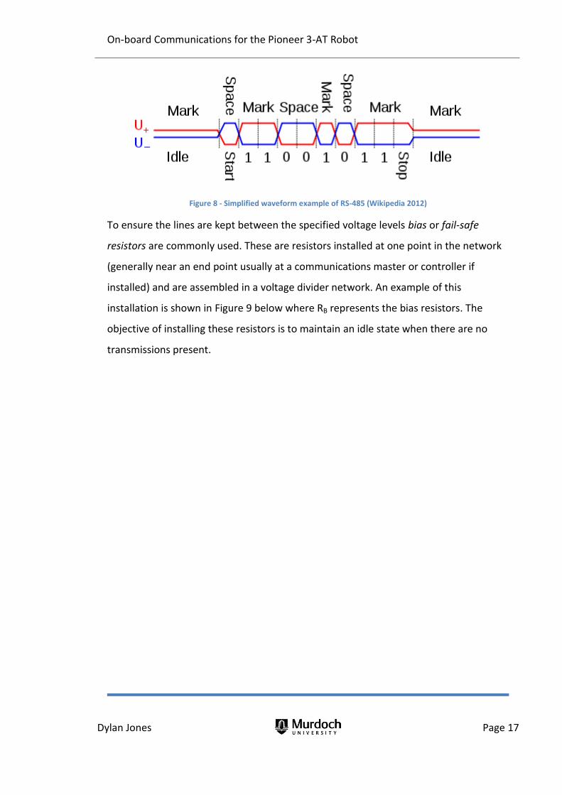
Implementation of the bi-directional half duplex is effected by reversing the polarity of
the two signal wires by the sending node’s driver to indicate the system is ready to
begin transmission. This concept is shown in Figure 8 below and is known as line
assertion (line A is represented by U+ and line B uses U-). Other nodes are able to
detect that the line is asserted and stand by to receive a transmission as well as also
locking these receiving nodes from sending. Due to the process of asserting the lines,
the signal wire that is positive (with respect to the other signal wire) when idle
becomes negative when the line has been asserted and before transmission occurs.
RS-485 operates with a signal range between -7Vdc and +12Vdc with voltages between
-200mV and +200mV undefined. If the line B voltage is between 200mV and 12V
greater than the line A voltage a binary one, which is referred to as a mark, is
registered. If the voltage of line A is between 7 and 0.2 volts less than line B, a space is
registered. The period where the line is not asserted is referred to as being idle.
On-board Communications for the Pioneer 3-AT Robot
Dylan Jones Page 17
Figure 8 - Simplified waveform example of RS-485 (Wikipedia 2012)
To ensure the lines are kept between the specified voltage levels bias or fail-safe
resistors are commonly used. These are resistors installed at one point in the network
(generally near an end point usually at a communications master or controller if
installed) and are assembled in a voltage divider network. An example of this
installation is shown in Figure 9 below where RB represents the bias resistors. The
objective of installing these resistors is to maintain an idle state when there are no
transmissions present.

On-board Communications for the Pioneer 3-AT Robot
Dylan Jones Page 18
Figure 9 - Example of bias resistor installation (Kugelstadt 2011)
Node hierarchy
The electrical characteristics are not the only considerations to make for the physical
network. To be successfully implemented, it is important to specify what data needs to
be transferred and by which microcontrollers. Presently there are two microcontrollers
that require communications – the main 68HC11 microcontroller and the differential
global positioning system (DGPS) microcontroller. A third system has also been
developed, a video and payload systems microcontroller, yet given the high bandwidth
requirements of video transmission, the image and associated ranging and control
signals will be communicated separately.
Given there will be multiple nodes requiring access to the communications bus, two
styles of communication have been considered. These are: (i) a master slave
arrangement, or (ii) a token ring. A token ring is generally implemented using a daisy

On-board Communications for the Pioneer 3-AT Robot
Dylan Jones Page 19
chain topology, however may also be implemented on a bus. Communication is only
permitted by the node holding the ‘token’ which is passed from node to node. The
master-slave arrangement can be implemented on a bus topology and uses a
communications master who determines which node will communicate and when. For
this particular project, the master-slave topology will be implemented primarily due to
the fact that all communications will be via the master.
A master slave arrangement will allow for a level of control over communications that
a token ring cannot. Given the Pioneer Robot will operate transferring both analogue
and digital signals between microcontrollers, there will need to be an opportunity for
urgent data to be transferred, with the possibility of the need arising midway through
routine scheduled data transfers. The master-slave arrangement will hopefully also
avoid communication collisions and will require the use of addressing so each node will
know when the received message is intended for it.
Other considerations that need to be made when considering a communications
system will be data transfer scheduling. In addition to the routine transfer that will
occur, allowances for exceptional events will need to be considered. One possible
implementation would be that of a physical interrupt that may be to use a digital input
channel that is constantly monitored by the microcontroller. This is similar to the
system used by the SPI bus, but instead of the master signalling the slave, the slave
signals the master, by setting a line high. The purpose behind the interrupt is to signal
to the microprocessor that an exceptional event has taken place and an urgent
response is required. If a large number of nodes were to be attached to the bus, the
corresponding number of digital inputs would be required by the master to identify
the slave communicating. If there are a large number of slaves this system will not be
able to be cost effectively implemented.
Topology
There are several topographical arrangements that could be implemented in order to

On-board Communications for the Pioneer 3-AT Robot
Dylan Jones Page 20
reliably allow communications between nodes, and RS-485 is capable of operating
across many different network topologies. These are shown in Figure 10 below. Given
the small geographical distance between the nodes, a bus topology has been chosen.
Given the nature of the installation, a ring or mesh topology featuring redundant links
is not required. Using the chosen RS-485 communication standard will avoid the need
to implement a token ring communications protocol.
Figure 10 - Communications networks topologies (Rouse 2010)
Care should be taken when implementing the final bus to ensure any stub or spur
branches off the main bus are kept to a minimum. Having excessively long spurs can
affect the resultant waveform transmitted upon the bus. An example of this is shown
in Figure 11 below, which shows the same waveform transmitted over an RS-485
system that contains both a three metre spur line to a node and another that only
utilises short spurs.

On-board Communications for the Pioneer 3-AT Robot
Dylan Jones Page 21
Figure 11 - Resultant waveforms from a system with a 3 metre spur (left) and short spurs (right) (Maxim Integrated 2001)
3.3 Objective P2: Specify the required hardware
It has been determined that the Pioneer Robot protocol will operate using an RS-485
physical layer, so the next step is to specify and source the required hardware in order
to implement the network. Currently there are two nodes that need to be connected:
(i) the communications master (New Micros 68HC11), and (ii) the DGPS controller
(Arduino mega). It has been found that a communications card to suit the New Micros
68HC11 microcontroller, a New Micros NMIS 5000, is currently held by the technical
department of the School of Engineering and Energy. The datasheet for the NMIS 5000
is attached in Appendix B – NMIS 5000 Datasheet.
For the Arduino, a little more engineering was undertaken. A conversion circuit was
required to convert the 3.3V transistor-transistor logic (TTL) signals from the Arduino
to the higher voltages utilised in the RS-485 network. A suitable prototyping board was
sourced from nuelectronics.com with which a ‘shield’ was constructed using a National
Semiconductors DS75176BN converter chip. The National Semiconductors chip has
almost identical characteristics and the same pinout to the Max485 chip so the circuit
diagram shown in Figure 12 below was used, with the exception of the omission of the
termination resistor. A datasheet for the DS75176BN converter chip has been attached
in Appendix D – DS75176BN Datasheet.

On-board Communications for the Pioneer 3-AT Robot
Dylan Jones Page 22
Figure 12 - Max485 wiring diagram (Arduino 2012)
3.4 Defining the protocol
In order to have an effective communications protocol for the transmission of data, a
structured format that each node MUST adhere to needs to be developed. There are
many aspects requiring consideration, with some of the steps required to define the
protocol being: the data packet contents and assembly, hierarchy of nodes, addressing
of nodes, message types, responses to messages and error handling. Whilst the
protocol is originally being developed to operate on the RS-485 physical layer, there is
nothing to stop the protocol rules being applied to other physical layers.
Hierarchy and addressing
To begin with, we can define the node hierarchy. It is intended that the protocol will
be implemented in such a way that there will be one master node, the
communications master, with the rest being slave nodes, an arrangement commonly
referred to as a master-slave hierarchy. The communications master will be
responsible for all the messages passed across the communications network. The
remaining slave nodes will act as peers, with the option of introducing sub groups of

On-board Communications for the Pioneer 3-AT Robot
Dylan Jones Page 23
peers being retained for future use to add extra functionality to the protocol. The
master would be given address zero and all other nodes being assigned unique
addresses. With the use of RS-485, only 32 unit loads are available. This means that
while more than 32 addresses are available to be messaged, the RS-485 system will
only support a combined physical load of 32 slaves. There is however the ability to
expand this number by implementing repeating systems which could be investigated in
future if the need should arise.
It is anticipated that sub groups can be later implemented to communicate with
several nodes at the same time. Nodes that would be grouped together would most
likely be nodes performing a similar task. An example is drive motors. Presently the
drive motors are controlled using outputs from the master controller. In future, these
motors may be replaced by smart motors that have inbuilt communication units. If the
robot was required to travel forwards at full speed, a command could be sent to all the
drive motors simultaneously so that they all responded at the same time. This would
minimise bandwidth across the network. It does however introduce the issue of
message acknowledgement in that the master would need to know that the slaves
have acknowledged its request, and communications errors would occur if multiple
slaves replied at the same time.
Message interpretation and error detection
As with any communications method, there is the potential to have messages that are
received or interpreted differently by the receiver than was originally intended by the
sender. To avoid message perception problems, it is intended that a function code be
incorporated into the data packet structure. This would be set by the sender and read
by the receiver. If the function is understood, the receiver should reply appropriately
to acknowledge the message. If the message is not understood, the receiver should
reply with an unacknowledged message which could be actioned by subsequent
programming, which may include resending the message or a communications fail

On-board Communications for the Pioneer 3-AT Robot
Dylan Jones Page 24
error alert.
The function code implementation would require each node to contain a function code
library in order to understand each message addressed to it. In theory, each node
could use the same message codes but take different actions as tasks to perform. This
may become problematic however, due to confusion by programmers. It is therefore
intended that a single function serve a single purpose and not be reused by different
nodes.
There are many methods to implement error detection. A parity bit is perhaps the
most simple, implemented by setting a bit in a message high or low depending on (i)
how many high bits are contained in the message, and (ii) if parity is set to be odd or
even. Parity is often used in lower layers of the OSI model, however it could be
implemented at the application layer as well. Other error checking systems require
more processing, such as cyclic redundancy checks. For the Pioneer Robot protocol, it
has been decided to implement a simple summation or checksum. This process is
described in the implementation section of this report.
3.5 Objective P3: Protocol rules
This is a summary of the rules developed for the communications protocol:
1. All nodes shall have a unique address. Address 0 shall be reserved for
the master. Address 255 shall be reserved for an all nodes group
address.
2. Packets will generally be constructed in the format shown in Table 3
below.

On-board Communications for the Pioneer 3-AT Robot
Dylan Jones Page 25
Byte number Function
0 Message Length
1 Addressee
2 Function code
3 to (n-1) Data (optional)
n Checksum
Table 3 - Message packet structure
2.1 The message length value shall not include the message length
byte.
2.2 The checksum will consist of the sum of all the previous byte
values. Where characters are used as data (as in addressing, data,
function codes) they will be converted to ASCII codes which will be
summed to determine the checksum value.
3. There will two modes of communication – free bus and polled.
4. No slave will initiate communications unless either (i) the free bus has
been enabled, or (ii) the slave determines an emergency condition has
occurred.
5. Polled communications may consist of the master polling an individual
slave or multiple slaves.
6. The master may poll an individual slave:
6.1 The master will send a message in the format shown in Table 4
below.
Byte number Function
0 Message Length
1 Address of slave
2 Function code
3 to (n-1) Data for the slave (optional)
n Checksum
On-board Communications for the Pioneer 3-AT Robot
Dylan Jones Page 26
Table 4 - Polled data packet (from master)
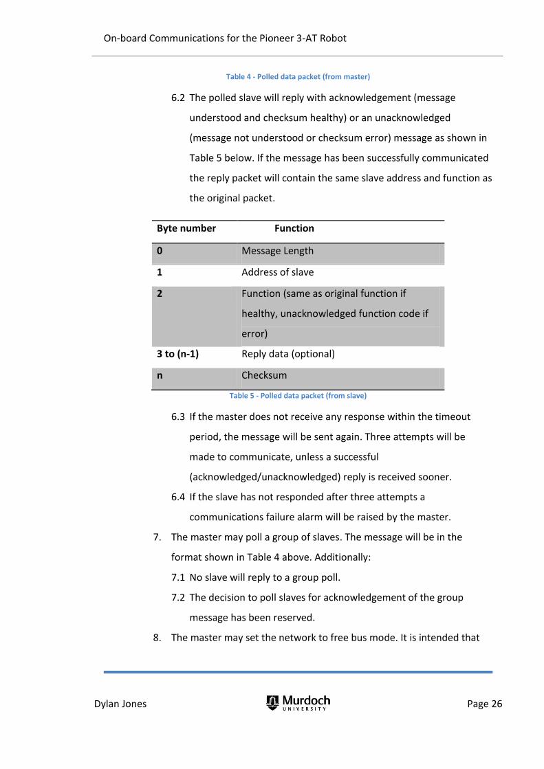
6.2 The polled slave will reply with acknowledgement (message
understood and checksum healthy) or an unacknowledged
(message not understood or checksum error) message as shown in
Table 5 below. If the message has been successfully communicated
the reply packet will contain the same slave address and function as
the original packet.
Byte number Function
0 Message Length
1 Address of slave
2 Function (same as original function if
healthy, unacknowledged function code if
error)
3 to (n-1) Reply data (optional)
n Checksum
Table 5 - Polled data packet (from slave)
6.3 If the master does not receive any response within the timeout
period, the message will be sent again. Three attempts will be
made to communicate, unless a successful
(acknowledged/unacknowledged) reply is received sooner.
6.4 If the slave has not responded after three attempts a
communications failure alarm will be raised by the master.
7. The master may poll a group of slaves. The message will be in the
format shown in Table 4 above. Additionally:
7.1 No slave will reply to a group poll.
7.2 The decision to poll slaves for acknowledgement of the group
message has been reserved.
8. The master may set the network to free bus mode. It is intended that

On-board Communications for the Pioneer 3-AT Robot
Dylan Jones Page 27
the network will be set to free bus mode unless the master is actively
polling slaves. Free bus mode will allow any slave to send a message to
the master.
8.1 Free bus mode will be disabled should any node send a message.
8.2 The packet sent by the master to indicate to all slaves that the
network is in free bus mode is shown in Table 6 below.
Byte number Function
0 Message Length (4)
1 Addressee (255)
2 Function (255)
3 Data (Free bus loop number 0 -number
of nodes)
4 Checksum
Table 6 – Initiate free bus message packet structure
8.3 Any slave addressing the master while in free bus mode will send a
message in the format shown in Table 7 below.
Byte number Function
0 Message Length
1 Address (Slave Address)
2 Function
3 to (n-1) Data
n Checksum
Table 7 – Free bus message packet structure (from slave)
8.4 The master will respond to the slave using a packet in the format
shown in Table 8 below.
Byte number Function

On-board Communications for the Pioneer 3-AT Robot
Dylan Jones Page 28
0 Message Length
1 Address (Slave Address)
2 Function
(Acknowledged/Unacknowledged)
3 to (n-1) Data (if required)
n Checksum
Table 8 – Free bus message packet structure (master acknowledgement)
8.5 If the slave does not receive an acknowledged packet within the
timeout period it will attempt to send the original packet again.
Three attempts will be made to communicate, unless a successful
(acknowledged/unacknowledged) reply is received sooner.
8.6 If the master has not responded after three attempts, a
communications error will be raised by the slave. The error will stay
active until such time as a healthy message addressed to the slave,
is received by the slave. If required, an attempt to send the
message will be made at the next opportunity when free bus mode
is enabled.
9. All nodes will be capable of entering an ‘emergency’ state.
9.1 The emergency state may be triggered by a condition within the
node itself or by receiving an emergency data packet.
9.2 If a node internally enters an emergency state, it will send an
emergency data packet to all other nodes. This is irrespective of
whether or not the network is in free bus mode. The packet will be
in the form shown in Table 9 below.
Byte number Function
0 Message Length
1 Addressee (255)
2 Function (Emergency – 251)

On-board Communications for the Pioneer 3-AT Robot
Dylan Jones Page 29
3 Data (Address of slave calling
emergency)
4 Checksum
Table 9 – Emergency message packet structure
9.3 The node will send this packet three times. Upon receiving this
message the master will again send the message three times.
9.4 The decision to poll slaves when the system is in an emergency
state has been reserved.

On-board Communications for the Pioneer 3-AT Robot
Dylan Jones Page 30
4. Building and refining the prototype network
4.1 Development outline
As discussed previously, the final protocol for the Pioneer Robot is currently required
to operate on two different platforms, a Motorolla 68HC11 microcontroller for the
communications master and the existing Arduino Mega for the DGPS slave. There is
also the prospect of the protocol operating on other types of microcontrollers in the
future, depending on how the project grows. Also previously discussed was the fact
that the protocol is intended to be implemented in a master slave relationship over an
RS-485 physical layer laid out in a bus topology. The application of the rules previously
developed can now be carried out in a laboratory environment in order to determine if
the protocol would achieve the required objectives.
Before tailoring the communications program to a single type of microcontroller, a
prototype program was developed. The prototype was developed as a generic form of
the protocol, adaptable to multiple platforms, using National Instrument’s Labview.
Labview was selected due to its graphical nature, which presented the best
opportunity to easily visualise the protocol in action. Labview allows users to program
in a graphical environment which can often speed up not only the design process, but
also the debugging and fault finding as well. Labview was found to be an efficient tool
for this purpose as well as providing an opportunity for user friendly front panels to be
built, enabling the rapid testing of data flows with real time visual feedback of the
program performance.
Before any progress could be made with testing and refining the protocol, a suitable
development environment needed to be created. The environment chosen was the
Mechatronics lab at Murdoch University’s South Street campus. The development of
the protocol was undertaken on three standard university desktop personal computers
(PCs), being the Dell Optiplex 790, using Labview and communicating through the on
board RS-232 serial ports. Labview was run within the Windows 7 operating system,

On-board Communications for the Pioneer 3-AT Robot
Dylan Jones Page 31
with one PC functioning as the master and the two others as slaves. The PCs used
during the development phase had the specifications mentioned in Table 10 below.
Parameter Specification
Computer Model Dell OptiPlex 790
BIOS Vendor Dell Inc.
BIOS Version DELL - 6222004
BIOS Date 09-10-11
Window Version Microsoft Windows 7 Enterprise
Processor Intel(R) Core(TM) i5-2500 CPU @
3.30GHz
Clock Speed 3.4GHz
L2 Cache Size 1024
RAM 8 GB
Table 10 - Development PCs specifications
The design process began using two computers and a very simple communications
program. Initially the two computers were connected using the serial port (COM1) on
both computers. Given that these are the only ports fitted to the computer, and they
actually use the RS-232 electrical standards, interface converters (Alfatron ASeries
A450) were employed to convert the RS-232 to the RS-485 intended to be used in the
Pioneer Robot. The A450 units have a number of user programmable dip switches, the
settings of the switches used for this project are shown in Table 11 below. The
interface converters are externally powered (although they functioned adequately
when unpowered) using a 9V DC power supply. They were connected together in a two
wire bus using ‘figure 8’ flexible low voltage PVC insulated 1.5 mm2 cable for the initial
phase of the protocol development. This initial stage was used to ensure the
computers were set up correctly and simple communications could be established
between them using the hardware mentioned previously. The figure 8 flexible cable
was eventually replaced by Profibus DP cable, as shown in Figure 13 below, to ensure

On-board Communications for the Pioneer 3-AT Robot
Dylan Jones Page 32
the testing of the prototype protocol was undertaken in an environment that closely
matched the final installation configuration as possible. Profibus DP cable is designed
to meet the required physical specifications of RS-485. The manual for the Alfatron
A450 is attached in Appendix C – Alfatron A450 Datasheet.
Switch Setting Description
DCE/DTE DCE Data communications equipment
Dip Sw 1 On
2 wire bus Dip Sw 2 On
Dip Sw 3 Off
Dip Sw 4 On LED on indicates active
Dip Sw 5 Off No termination resistance (4 wire RS-485
bus)
Dip Sw 6 Off No termination resistance (2 wire RS-485
bus)
Table 11 - A450 interface converter dip switch settings

On-board Communications for the Pioneer 3-AT Robot
Dylan Jones Page 33
Figure 13 - Alfatron interface converters shown connected
For this project, the interface between the Labview program and the hardware was
undertaken using the Virtual Instruments Software Architecture (VISA) interface. The
VISA interface consists of subVI’s which are called inside the Labview program. These
subVI’s are actually high level drivers (which are software programs to enable the
correct operating and functioning of a piece of hardware or device) that operate as an
interface between the Labview program and more low level or device specific drivers
(National Instruments 2007). Referring back to the OSI model, Labview would be the
uppermost application layer, VISA the next layer down and the actual device drivers
sitting just above perhaps the BIOS serial port controller and the physical layer.
4.2 Confirming communications
Once the physical network had been constructed the process of implementing, testing,
verifying and refining the rules of the protocol could begin. Initially there was only one

On-board Communications for the Pioneer 3-AT Robot
Dylan Jones Page 34
program which was duplicated on each machine. Either instance of the program could
be manually switched to perform either ‘read’ or ‘write’ actions. One program could
send a basic message to the other which would take some simple action, such as
turning on an indicator lamp. This phase of the project was important for reaching the
following outcomes:
a good understanding of Labview programming,
familiarisation with the hardware being utilised, and
initial testing of the protocol packet specification.
This was a very rudimentary communications program, however it enabled a good
understanding of the behaviour of the programming environment. Once these
concepts had been proven, the program was further developed to send a response
back to the master in order to understand basic automated responses. Part of this
program is shown in Figure 14 below.

On-board Communications for the Pioneer 3-AT Robot
Dylan Jones Page 35
Figure 14 - Original Master (write message code shown)

On-board Communications for the Pioneer 3-AT Robot
Dylan Jones Page 36
Once the network was shown to operate correctly, steps were taken to ensure the
appropriate settings were captured and maintained for all nodes to share. Part of this
is in determining the configuration settings of the network, which gives each node on
the network the ability to understand the physical layout of the packet structures. The
configuration settings used for these initial stages are shown in Table 12 below.
Parameter Setting
Data bits 8
VISA refnum in COM1
Flow Control None
Stop Bits 1.0
Parity None
Baud Rate 9600
Table 12 - Initial communications configuration settings
Aside from the VISA refnum in, which determines which physical port on the PC will be
used for communications, the configuration settings are required to be set identically
on each node communicating on the bus. It is for this particular purpose that the code
in Labview was condensed into a subVI which was reused by each PC during the
protocol development. This subVI is shown in Figure 15 below. The settings used as
shown in Table 12 were chosen as they were the default settings used by the VISA
setup and in the initial stages there was no apparent reason or need for changing
them.

On-board Communications for the Pioneer 3-AT Robot
Dylan Jones Page 37
Figure 15 - Communications configuration settings subVI
4.3 Developing a master slave relationship
After some basic functionality had been developed, two new programs based on the
original were then constructed – one master and one slave program, with the slave
program being designed to be duplicated as many times as necessary to simulate the
many slave nodes on the actual network. In the beginning of development, only one
slave was used on the communications bus; it was used to determine if the basic
communications concepts would function, in order to expedite program development
and testing. The initial master and slave programs were written using case statements
in such a way that they could be manually switched between the ‘read’ or ‘write’
activities. The programs have been written so both the master and slave programs
would default to ‘listen’ mode. If there had been activity detected then further action
described previously would be acted on. The user interface panels for the prototype
programs are shown in Figure 16 and Figure 17 respectively.

On-board Communications for the Pioneer 3-AT Robot
Dylan Jones Page 38
Figure 16 - Master prototype user interface (final)
Figure 17 - Slave prototype user interface (final)
4.4 Building data packets
The next task in developing the communications protocol was to determine precisely
in what format the data was to be sent across the network and how this would be
accomplished. As no status, control or other special bytes had been developed for the
prototype system, all messages were in a character format, either a letter or a number,
so transmitting the ASCII representation of the character made sense. It would be just
as easy to send a special status or control byte in the data field using the protocol too.
From the rules developed, each data packet would contain a message packet length,

On-board Communications for the Pioneer 3-AT Robot
Dylan Jones Page 39
address, function code, some data if required, and a checksum value.
Each of the components of the message would need to be assembled together into the
data packet ready for transmission. Given that both the master and any slave nodes
would both need to perform this activity it was again decided to build a subVI to
perform both the collating and assembly and another for the disassembly and
dissemination. Within Labview, the actual packet was assembled into an array that is
then sent element by element. The subVI that was developed to build the data packet
is shown in Figure 18 below, it has the inputs of address, function and data. These are
assembled into the message packet. The length byte is also added to the beginning of
the data packet, although it is not included in the calculated length of the data packet,
and an error detection byte is added at the end. The final packet is an output of this
subVI.
Figure 18 - Message packet construction subVI
Similarly, at the other end of the communications link, the message packet needs to be
stripped out into its components (array elements) to understand what the sender
intends with the message. This process is shown in Figure 19 below. Essentially this
process is a reversal of the building process, whereby each element of the array is

On-board Communications for the Pioneer 3-AT Robot
Dylan Jones Page 40
removed from the array and stored ready to be actioned. There are however two
exceptions to this, the message length and the checksum. As the message packet
arrives at the node read buffer and before the message is stripped down, the message
length is removed from the beginning of the packet in order for the node to determine
how many bytes to expect in the read buffer. The node then reads this number of
bytes from the buffer and splits the message out into the function, address and the
data. The output of this subVI is the components of the message (the function, the
address and the data) as well as a checksum healthy flag which will be discussed in the
next paragraph.
Figure 19 - Original unpack message subVI
4.5 Error detection
According to rule three of the proposed protocol rules, a checksum should be
implemented to detect data packets that have not been transferred correctly. Looking
closely at Figure 18, this error detection implementation can be seen. It was decided
that a basic process should be used in order to keep future slave processing to a
minimum. The final detection technique chosen to be implemented is perhaps also the
simplest concept to understand, the checksum, which is simply a summation of the
corresponding ASCII value (binary representation of each character) of each byte in the

On-board Communications for the Pioneer 3-AT Robot
Dylan Jones Page 41
data packet. In the Labview implementation, it is the summation of the elements in the
array before it is sent. This value is then appended to the end of the data packet. It
should also be noted in Figure 18 that the extra functionality of using a wrong
checksum value in the message packet has been added for the purpose of testing the
checksum function during development. After the rest of the message has been read
from the buffer and before it is stripped down, the elements of the array are summed
and this value is compared to the checksum value. If the two are equal then the
message is deemed to be healthy and a checksum OK flag is set true (high) and, along
with the function the address and the data, used as an output from the subVI.
4.6 State machine implementation
Once the two major components of the communications network, which are the
physical communications between the nodes and the format of the messages
described by the protocol, had been implemented and proven to work, a system to
test the rest of the rules could be developed and placed into practice. In order to do
this properly at real time speeds, an automated system needed to be developed. This
was accomplished by further developing the previously mentioned master slave
programs using state machine methodology.
There is a large number of ways the testing and refining of the protocol rules could be
accomplished, so careful consideration toward the best means that would allow for
present and future functionality was required. To begin with, five states were
developed: ‘Listen’, ‘Initiate’, ‘Reply’, ‘Process’ and ‘Emergency’. Both master and slave
nodes were designed so that they would always default to the listen state, in order to
monitor the communications network for traffic. If a message was detected, it would
then transition to the process state. Similarly, in the master node, if an operator
wished to send a message it would transition to the ‘Reply’ state. In the case of the
slave node, if the machine detected a message, it would transition to the process state,
process the message, and if necessary transition to the send state to send a reply if
necessary. The machines could be ‘locked out’ in the emergency state if an emergency

On-board Communications for the Pioneer 3-AT Robot
Dylan Jones Page 42
stop button (only added to slaves in the early prototypes) was pressed or an
emergency stop data packet was received on the bus.
As the protocol was tested, further refinements were made and the machines became
more and more complex. An example of an early version of the master state machine
is shown in Figure 20 below. The slave has also generally been designed with very
similar functionality; the differences will be highlighted as they arise. Figure 20 shows
the master in the default ‘Listen’ state where the machine is dormant, waiting for
either an input from an operator or a message across the bus. The test machine has
been designed as described in the following paragraphs.
Figure 20 - Early state machine implementation
The Labview model of the state machine has been broken up broadly into a number of

On-board Communications for the Pioneer 3-AT Robot
Dylan Jones Page 43
different areas which control different aspects of the program. Returning to Figure 20,
the various areas can be seen highlighted, numbered and boxed where appropriate.
Although this early version of the program shown above appears complex the final
version is even more so. Beginning with number one is the code that controls the state
transition. From the ‘Listen’ state the machine is able to transition to the ‘Process’
state if it receives a message on the bus. It is also designed to transition to the ‘Initiate’
state if, after twenty seconds, the master has been dormant. This sends a free bus
enabled data packet to all the slave nodes. There is similar code in the other states to
move between states depending upon conditions encountered by the state machine.
Item two simply highlights the case structures that are used to update the received bus
if a new message is received. There are similar structures on the send bus also, that
update when a message has been built and is ready to send.
Item three is used to determine the address number. For the master this uses a
constant which sets the address to zero. For the slaves this address can be changed to
suit the address of the slave in the system. In Figure 20, the item numbered four is the
input to the case (machine state) selector. At this point it should also be noted that the
items outside the outer grey lines (which represent a ‘while’ loop) are initialisation
values and remain the same once the program has started until it is stopped. Item five
is a controller to adjust the cycle time which pauses the program for the amount of
time the user inputs so that the program doesn’t run continuously and use all the PCs
CPU resources. The next four items reference the internal busses used by the machine.
Within the machine there are four buses, which are implemented using shift registers.
These in turn act in a similar fashion to local variables in order for each state to have
access to them. These busses are shown numbered in Figure 20 previously: six - sent
message bus, seven – received message bus, eight – free bus enabled bus, and nine –
communications bus. These busses are available to all states of the machine and are
able to be updated by each state. The values stored on the bus are passed back from
state to state using the shift registers. The communications bus features two ‘wires’:

On-board Communications for the Pioneer 3-AT Robot
Dylan Jones Page 44
the configuration wire and the error wire. These are used by each VISA instance to
operate with the correct protocol settings and to feedback errors. The other busses
are a little more complex.
The received message bus features three wires: address, function and data. The blue
wire shown for the function and address node indicates a numeric data type while the
pink wire indicates a string data type. As mentioned previously, this bus is updated if a
new and valid (checksum healthy) message is received by the node through the use of
case statements. In the slaves, the additional requirement of the received address
corresponds to that of the slave before the bus is updated. The sent message bus
operates the same as the received message bus, except that the data on the bus
comes from the operator and not from the bus. It can also be observed that there are
indicators attached to both the send and receive buses so that an operator can easily
identify the messages being sent and received.
4.7 Free bus implementation
From Figure 20 the final bus is the free message bus. The free bus is a concept set in
the protocol rules to allow nodes to communicate to the master without being polled.
This would occur if there is an important message to send such as a digital input that
does not necessarily need to be polled on a routine basis. In the master this bus is set
to true when the free bus message is created and ready to be sent. In a slave it is set to
true if the slave node receives a free bus message, which is described in rule 10 of the
protocol rules, and simply has an address of 255 and a function of 255. It is returned to
false whenever a new message is received (or any other activity on the bus is detected)
or an emergency condition occurs.
It was found in later testing that the process of free bus may not function as expected,
resulting in miscommunications. In the initial prototype design each slave node was
able to attempt to send a message as soon as they had received a free bus message
and the free bus had been enabled within the machine. This means that there was
nothing stopping two nodes trying to communicate at the same time as soon as the
On-board Communications for the Pioneer 3-AT Robot
Dylan Jones Page 45
free bus had been enabled. This is a problem because when this occurs both slaves
assert line A high before they begin to transmit. This means that there is the potential
for no message to be transmitted as line A may be held high by one slave when the
other slave is attempting to drop it back low to signal a high (or ‘on’). Any other node
attempting to receive this message may encounter a framing error where, due to the
overlapped bits within the data packet, the message is incomprehensible. In the
prototype model this occurred in the VISA system in a lower (possibly hardware) level
layer that was handled by the serial port drivers and not by the Pioneer Robot
protocol.
To overcome this problem, a new element to the program was added. Ideally the
solution would be to test for the asserted line at a hardware level and disable any
transmission if this was detected. A means of performing this using VISA subVIs in
Labview was not apparent, so instead a scheduling approach was developed and is
shown implemented in Figure 21 below. This approach works by adding a number
(between zero and one minus the number of slaves in the system) in the data field of a
free bus message as sent by the communications master. When the free bus message
is received by the slave it uses this number as a column reference along with its slave
address as a row reference to access an element in a matrix (shown as one in Figure 21
below) of size determined by the number of slaves in the system. The number that is
returned is placed on a delay bus (shown in item four in Figure 21) to be used as a time
delay before it can begin transmitting a free bus message.
The matrix used to determine this time delay is identical for all slaves on the system
and works by rotating the time delay between the slaves. In the first instance slave one
will receive no delay, slave two will receive a one millisecond delay, slave three will
receive a two millisecond delay and so on. On the next instance of free bus enabled
slave one will receive the maximum delay, slave two no delay, slave three a one
millisecond delay and so on. This approach is used in order to share the access equally
between the slaves, to ensure that no one slave can constantly ‘hog’ the bus during
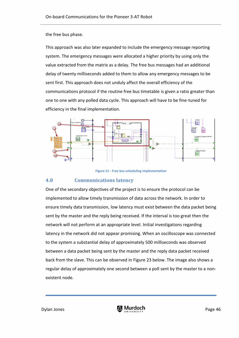
On-board Communications for the Pioneer 3-AT Robot
Dylan Jones Page 46
the free bus phase.
This approach was also later expanded to include the emergency message reporting
system. The emergency messages were allocated a higher priority by using only the
value extracted from the matrix as a delay. The free bus messages had an additional
delay of twenty milliseconds added to them to allow any emergency messages to be
sent first. This approach does not unduly affect the overall efficiency of the
communications protocol if the routine free bus timetable is given a ratio greater than
one to one with any polled data cycle. This approach will have to be fine-tuned for
efficiency in the final implementation.
Figure 21 - Free bus scheduling implementation
4.8 Communications latency
One of the secondary objectives of the project is to ensure the protocol can be
implemented to allow timely transmission of data across the network. In order to
ensure timely data transmission, low latency must exist between the data packet being
sent by the master and the reply being received. If the interval is too great then the
network will not perform at an appropriate level. Initial investigations regarding
latency in the network did not appear promising. When an oscilloscope was connected
to the system a substantial delay of approximately 500 milliseconds was observed
between a data packet being sent by the master and the reply data packet received
back from the slave. This can be observed in Figure 23 below. The image also shows a
regular delay of approximately one second between a poll sent by the master to a non-
existent node.

On-board Communications for the Pioneer 3-AT Robot
Dylan Jones Page 47
Figure 22 - Send-reply cycle observed in the prototype
Investigations were made into the cause of this latency. All delays that had been
purposely introduced to allow the system to wait on events were removed. Three
exceptions were made, these were the delay between the assertion of the line and
the beginning of transmission of the data packet (reduced to one millisecond), the
delay before de-asserting the line after sending the data packet (again one millisecond)
and the delay in checking the port for a new message (also one millisecond). With
these delays removed the latency still remained. One possible explanation is that the
delays are introduced as part of the VISA read and write subVIs. The polling cycle code
is shown in Figure 23. This delay between the polls to non-existent nodes is interesting
as during the polling testing the maximum number of polls was set to around 350
which equates to a 350 millisecond delay.

On-board Communications for the Pioneer 3-AT Robot
Dylan Jones Page 48
Figure 23 - Poll cycle

On-board Communications for the Pioneer 3-AT Robot
Dylan Jones Page 49
One area that latency may propagate is in the microcontroller itself and may be caused
by delays due to processing other code. The original concept implemented for polling
data was to (i) send the message, then (ii) wait for 500 milliseconds, and (iii) then read
the contents of the buffer where hopefully the reply was waiting. There was no check
prior to reading from the port to ensure a reply had first been received. This
methodology was later changed to check the port first before reading from it. If there
was a delay introduced by the original methodology, it would more so affect the
processing of other functions of code rather than affecting the communications
latency.
Finally in attempt to increase communications speed the original communications
settings were revisited. The baud rate was increased from the original 9600 baud to
115200 baud, an increase in communications speed of 12 times. The results of this
change can be seen in Figure 24 and Figure 25 below. Figure 24 also shows the original
line asset and de-assert times of 10 and 40 milliseconds while those seen in Figure 25
show the reduced times of 5 milliseconds for both. The data packet took significantly
less time to transmit, going from ten milliseconds at 9600 baud to approximately three
milliseconds at 115200 baud. While the time to transmit the packet dramatically
decreased the latency between the sent packet and the returned packet still remained.

On-board Communications for the Pioneer 3-AT Robot
Dylan Jones Page 50
Figure 24 - Free Bus message sent at 9600 baud

On-board Communications for the Pioneer 3-AT Robot
Dylan Jones Page 51
Figure 25 - Free Bus message sent at 9600 baud

On-board Communications for the Pioneer 3-AT Robot
Dylan Jones Page 52
5. Conclusion
The objective of this project was to specify and develop a communications protocol to
be implemented on the Pioneer Robot. This general objective was expanded on to give
some clear lower level objectives to enable goals to be set in order to accomplish this
objective. While the protocol was not implemented in the final microcontroller
environment, a prototype version was successfully implemented.
Firstly the physical layer has been specified to be RS-485 and was able to be
implemented using PCs in a laboratory environment. Network adapters were also
specified and sourced, with a NMIS 5000 to suit the 68HC11 available off the shelf. A
shield was constructed using a DS75176BN chip as the interface between the RS-485
network and the TTL used by the processor. The NMIS 5000 RS-485 card for the
68HC11 microcontroller has a maximum baud rate of only 38400 which may become
the limiting factor in the final microcontroller network speed.
The last objective was to develop a new protocol to network the microcontrollers on-
board the Pioneer Robot. It was shown through prototyping that a new
communications protocol could be successfully developed for a microcontroller
communications system. The original purpose of developing a new protocol was to
limit the memory required to store the protocol as well as the processing power to
implement it. The protocol developed was more complex than first envisaged however
refinements may be able to cut back some of the overhead, particularly by
programmers with a knowledge of programming more intimate than this author.
Although the exact data required to be transmitted has not been determined, the
format of the communications protocol will allow for all manner of messages to be
transmitted.

On-board Communications for the Pioneer 3-AT Robot
Dylan Jones Page 53
6. Future work
6.1 Prototyping
There are several issues that still require finalising in the prototyping program before
migrating the protocol to the final implementation.
Length testing
While not currently required, there was no maximum length specified for the protocol.
It would be prudent to look at two areas to ensure a maximum message size is
specified if required. These two areas are:
(i) The maximum buffer sizes used by the devices in the final implementation
to ensure no communications overflows occur,
(ii) Efficient data transmission. Messages may have to be broken into smaller
messages so other equally important messages are transmitted in a timely
manner.
Latency
The cause of the latency documented in Section 4.8 can be further investigated to find
the source. While it may be a problem particular to the prototype environment it
should be investigated to ensure this latency is not carried into the final product.
Data collisions
A system was developed and implemented to allow scheduling for messages in the
free bus phase. It is intended that this should also be applied to emergency messages
but was not implemented in the prototyping program. The system uses the delay
introduced by the time delay matrix previously discussed, and the delay used by each
node changes each time the free bus mode is enabled. It was originally intended that a
node could send an emergency message at any time, however this arrangement may
cause data collisions so it was decided that emergency messages should wait until free

On-board Communications for the Pioneer 3-AT Robot
Dylan Jones Page 54
bus mode to be sent. The emergency message would have priority over all other
routine messages.
6.2 Implementation
The most obvious next step in implementing the Pioneer Robot protocol is to migrate
the prototype program from Labview to both the 68HC11 microcontroller and the
Arduino. Given the complexity of the state machine that was developed for the
prototype it may be easier to begin again using the rules defined previously rather
than translating the Labview code.
The development of functioning code took much longer than anticipated. An outcome
of the extended development phase was less time to test the code that had been
produced. Therefore, after implementing the code in the 68HC11 system, some
significant time should be set aside to function test the system and check for
communications issues. This should ideally be performed with multiple nodes
connected to the network, all engaged in routine scheduled communications.
Exceptional events as well as emergency conditions should then be triggered in several
nodes to test that data collisions do not occur. While the final code has been altered to
eliminate collisions using the scheduling matrix, it has not been ’in depth’ and
adequately tested.
Once the protocol is developed in the microcontroller environment the next step is to
determine the actual data that will be sent across the network. This will need to be
undertaken in conjunction with a thorough understanding of the coding in each
microcontroller as implementation could be performed in a variety of ways. An
example of this is communications between the master control microcontroller and
the DGPS microcontroller. Would it be more efficient to send a co-ordinate from the
master to the DGPS, which in turn calculates the required direction and range to
travel? Or is it more expedient to send the co-ordinate from the DGPS system to the
master microcontroller? These questions will need to be answered by all future

On-board Communications for the Pioneer 3-AT Robot
Dylan Jones Page 55
communicating microcontrollers and the data they need to share.
Another interesting area of research is intelligent nodes. A potential application of this
thesis is to research and implement smart devices that are controlled via the Pioneer
Robot protocol. An example is drive motors, where only the full power and a network
cable are supplied to the motor. The master controller microcontroller would still
control the motor, however the control would be implemented by the microcontroller
communicating with the motor directly using the Pioneer Robot protocol, rather than
controlling through an external motor controller.
Finally the issue of testing for line assertion on the RS-485 network by nodes wishing to
communicate during the free bus phase could be undertaken. This may potentially
counter the requirement to schedule free bus and emergency messages.

On-board Communications for the Pioneer 3-AT Robot
Dylan Jones Page 56
7. Bibliography
Arduino. Arduino Forum. 17 November 2012.
http://arduino.cc/forum/index.php?action=profile;u=27258;sa=showPosts
(accessed November 17, 2012).
Churcher, Bradley J. Differential Global Positioning System. Honours Thesis, Perth:
Murdoch University, 2011.
Doyle, Finbarr. Pioneer Robot Upgrade. Honours Thesis, Perth: Murdoch University,
2010.
High Tech Horizon. “Scaleable Network Addressable Protocol.” High Tech Horizon's On-
Line Catalog. 25 October 2002.
http://www.hth.com/filelibrary/pdffiles/snap.pdf (accessed October 2, 2012).
Kugelstadt, Thomas. Implement Idle-Bus Failsafe In Multipoint Networks. 28 November
2011. http://electronicdesign.com/article/communications/implement-idle-
bus-failsafe-in-multipoint-networks (accessed November 11, 2012).
Lammert Biers. “RS485 serial information.” Lammertbies. 11 November 2012.
http://www.lammertbies.nl/comm/info/RS-485.html (accessed November 11,
2012).
Leavy, Andrew. Developing a Sensor Payload Module for the Pioneer Robot. Honours
Thesis, Perth: Murdoch University, 2012.
Maxim Integrated. “Guidelines for Proper Wiring of an RS-485 (TIA/EIA-485-A)
Network.” Maxim Integrated. 19 November 2001.
http://pdfserv.maximintegrated.com/en/an/AN763.pdf (accessed November
11, 2012).
Microsoft. Data Flow in the OSI Model. 2012. http://technet.microsoft.com/en-
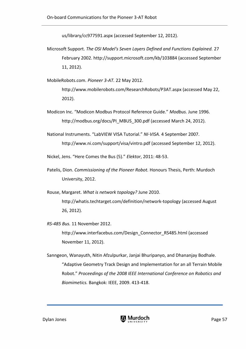
On-board Communications for the Pioneer 3-AT Robot
Dylan Jones Page 57
us/library/cc977591.aspx (accessed September 12, 2012).
Microsoft Support. The OSI Model's Seven Layers Defined and Functions Explained. 27
February 2002. http://support.microsoft.com/kb/103884 (accessed September
11, 2012).
MobileRobots.com. Pioneer 3-AT. 22 May 2012.
http://www.mobilerobots.com/ResearchRobots/P3AT.aspx (accessed May 22,
2012).
Modicon Inc. “Modicon Modbus Protocol Reference Guide.” Modbus. June 1996.
http://modbus.org/docs/PI_MBUS_300.pdf (accessed March 24, 2012).
National Instruments. “LabVIEW VISA Tutorial.” NI-VISA. 4 September 2007.
http://www.ni.com/support/visa/vintro.pdf (accessed September 12, 2012).
Nickel, Jens. “Here Comes the Bus (5).” Elektor, 2011: 48-53.
Patelis, Dion. Commissioning of the Pioneer Robot. Honours Thesis, Perth: Murdoch
University, 2012.
Rouse, Margaret. What is network topology? June 2010.
http://whatis.techtarget.com/definition/network-topology (accessed August
26, 2012).
RS-485 Bus. 11 November 2012.
http://www.interfacebus.com/Design_Connector_RS485.html (accessed
November 11, 2012).
Sanngeon, Wanayuth, Nitin Afzulpurkar, Janjai Bhuripanyo, and Dhananjay Bodhale.
“Adaptive Geometry Track Design and Implementation for an all Terrain Mobile
Robot.” Proceedings of the 2008 IEEE International Conference on Robotics and
Biomimetics. Bangkok: IEEE, 2009. 413-418.

On-board Communications for the Pioneer 3-AT Robot
Dylan Jones Page 58
Soltero, Manny, Jing Zhang, Chris Cockril, Kevin Zhang, Clark Kinnaird, and Thomas
Kugelstadt. RS-422 and RS-485 Standards Overview and System Configurations.
Application, Dallas: Texas Instruments, 2010.
Wikipedia. RS-485. 11 November 2012. http://en.wikipedia.org/wiki/RS-485 (accessed
November 11, 2012).
Zimmerman, Karl, and Edmund O Schweitzer III. “Substation Communications: When
Should I Use EIA-232, EIA-485, And Optical Fiber?” Western Protective Relay
Conference. Spokane: Schweitzer Engineering Laboratories Inc, 1996.

On-board Communications for the Pioneer 3-AT Robot
Dylan Jones
Appendix A - Pioneer 3-AT robot datasheet
Sourced from http://www.mobilerobots.com/Libraries/Downloads/Pioneer3AT-P3AT-
RevA.sflb.ashx (Accessed 22/5/2012)

On-board Communications for the Pioneer 3-AT Robot
Dylan Jones

On-board Communications for the Pioneer 3-AT Robot
Dylan Jones

On-board Communications for the Pioneer 3-AT Robot
Dylan Jones
Appendix B – NMIS 5000 Datasheet

On-board Communications for the Pioneer 3-AT Robot
Dylan Jones
Appendix C – Alfatron A450 Datasheet

On-board Communications for the Pioneer 3-AT Robot
Dylan Jones
Appendix D – DS75176BN Datasheet

On-board Communications for the Pioneer 3-AT Robot
Dylan Jones
Appendix E – Prototype protocol program
As provided on accompanying compact disk.
Note: The Master Controller program is labelled “Comms State Machine Master” and
the slave program “Comms State Machine Slave 1”. Only these two programs need to
be opened as the other dependencies should load from them.