Embed Size (px)
Citation preview

On Advancing the Topology Optimization Technique to
Compliant Mechanisms and Robots
A Thesis Submitted to the College of
Graduate Studies and Research
In Partial Fulfillment of the Requirements
For the Degree of Doctor of Philosophy
In the Department of Mechanical Engineering
University of Saskatchewan
Saskatoon
By
Lin Cao
Copyright Lin Cao, March 2015. All rights reserved.

i
PERMISSION TO USE
In presenting this thesis in partial fulfilment of the requirements for a Postgraduate
degree from the University of Saskatchewan, I agree that the Libraries of this University may
make it freely available for inspection. I further agree that permission for copying of this thesis
in any manner, in whole or in part, for scholarly purposes may be granted by the professor or
professors who supervised my thesis work or, in their absence, by the Head of the Department or
the Dean of the College in which my thesis work was done. It is understood that any copying or
publication or use of this thesis or parts thereof for financial gain shall not be allowed without
my written permission. It is also understood that due recognition shall be given to me and to the
University of Saskatchewan in any scholarly use which may be made of any material in my
thesis.
Requests for permission to copy or to make other use of material in this thesis in whole or
part should be addressed to:
Head of the Department of Mechanical Engineering
Engineering Building
57 Campus Drive
University of Saskatchewan
Saskatoon, Saskatchewan
Canada
S7N 5A9

ii
ABSTRACT
Compliant mechanisms (CMs) take advantage of the deformation of their flexible
members to transfer motion, force, or energy, offering attractive advantages in terms of
manufacturing and performance over traditional rigid-body mechanisms (RBMs). This
dissertation aims to advance the topology optimization (TO) technique (1) to design CMs that are
more effective in performing their functions while being sufficiently strong to resist yield or
fatigue failure; and (2) to design CMs from the perspective of mechanisms rather than that of
structures, particularly with the insight into the concepts of joints, actuations, and functions of
mechanisms. The existing TO frameworks generally result in CMs that are much like
load-bearing structures, limiting the applications of CMs. These CMs (1) do not have joints, (2)
are actuated by a translational force, and (3) can only do simple work such as amplifying motion
or gripping.
Three TO frameworks for the synthesis of CMs are proposed in this dissertation and they
are summarized below.
First, a framework was developed for the design of efficient and strong CMs. The widely
used stiffness-flexibility criterion for CM design with TO results in lumped CMs that are
intrinsically efficient in transferring motion, force, or energy but are prone to high localized
stress and thus weak to resist yield or fatigue failure. Indeed, distributed CMs may have a better
stress distribution than lumped CMs but have the weakness of being less efficient in motion,
force, or energy transfer than lumped CMs. Based on this observation, the proposed framework
rendered the concept of hybrid systems, hybrid CMs in this case. Further, the hybridization was
achieved by a proposed super flexure hinge element and a design criterion called input stroke

iii
criterion in addition to the traditional stiffness-flexibility criterion. Both theoretical exploration
and CM design examples are presented to show the effectiveness of the proposed approach. The
proposed framework has two main contributions to the field of CMs: (1) a new design
philosophy, i.e., hybrid CMs through TO techniques and (2) a new design criterion—input
stroke.
Second, a systematic framework was developed for the integrated design of CMs and
actuators for the motion generation task. Both rotary actuators and bending actuators were
considered. The approach can simultaneously synthesize the optimal structural topology and
actuator placement for the desired position, orientation, and shape of the target link in the system
while satisfying the constraints such as buckling constraint, yield stress constraint and valid
connectivity constraint. A geometrically nonlinear finite element analysis was performed for
CMs driven by a bending actuator and CMs driven by a rotary actuator. Novel parameterization
schemes were developed to represent the placements of both types of actuators. A new valid
connectivity scheme was also developed to check whether a design has valid connectivity among
regions of interest based on the concept of directed graphs. Three design examples were
constructed and a compliant finger was designed and fabricated. The results demonstrated that
the proposed approach is able to simultaneously determine the structure of a CM and the optimal
locations of actuators, either a bending actuator or a rotary actuator, to guide a flexible link into
desired configurations.
Third, the concept of a module view of mechanisms was proposed to represent RBMs
and CMs in a general way, particularly using five basic modules: compliant link, rigid link, pin
joint, compliant joint, and rigid joint; this concept was further developed for the unified synthesis
of the two types of mechanisms, and the synthesis approach was thus coined as module

iv
optimization technique—a generalization of TO. Based on the hinge element in the finite
element approach developed at TU Delft (Netherlands in early 1970), a beam-hinge model was
proposed to describe the connection among modules, which result in a finite element model for
both RBMs and CMs. Then, the concept of TO was borrowed to module optimization,
particularly to determine the “stay” or “leave” of modules that mesh a design domain. The salient
merits with the hinge element include (1) a natural way to describe various types of connections
between two elements or modules and (2) a provision of the possibility to specify the rotational
input and output motion as a design problem. Several examples were constructed to demonstrate
that one may obtain a RBM, or a partially CM, or a fully CM for a given mechanical task using
the module optimization approach.

v
ACKNOWLEDGEMENTS
Four years ago, Professor W. J. (Chris) Zhang, my supervisor, showed me a compliant
mechanism that was fabricated as a single piece of material and was used for cell manipulation.
It was at that moment my journey on compliant mechanisms started, along with curiosity as well
as wonders and questions. I am grateful for the unique guidance received from Professor Zhang
who is knowledgeable, insightful, and open-minded. I was always challenged by Professor
Zhang to criticize the literature, raise questions, come up with new ideas, implement the ideas,
and eventually develop publishable papers. He often encouraged me to generalize things and
look for the essence of problems. He also gave me much freedom to develop my own ideas and
to think and work independently. His encouragement was the great motivation for me to keep
exploring.
I would like to express my sincere gratitude to Professor A. T. Dolovich, my
co-supervisor, for his help and guidance on my research. I appreciate his efforts to teach me FEA.
He was always willing to explain things with fundamental concepts, which turns mathematic
equations into amazing logic thoughts. His attitudes to research and teaching were impressive.
Although his health condition was not quite well, he tried his best to meet me for discussions; I
always remember that he insisted on teaching the course of Finite Elasticity although he had to
sit in a wheelchair. I am also grateful for his suggestions regarding my future career.
I would like to thank other committee members, Professor D. Chen, Professor M.
Boulfiza, and Professor A. Odeshi for their valuable suggestions and insightful questions. P.Eng
R. Retzlaff from the Engineering Workshop helped fabricate the prototype of a compliant finger
(used in the Chapter 6) that I designed, and he is also acknowledged.

vi
I want to extend my gratitude to Professor A. Schwab who was my instructor during my
stay at the Delft University of Technology. He helped me a lot with SPACAR, and his comments
during our meetings have also deepened my understanding to my work. I also appreciate his
considerate help on my daily life in Delft. My gratitude also goes to Professor J. Meijaard from
the University of Twente for his help with SPACAR.
I have broaden my horizons during my stay in the lab of Interactive Mechanisms directed
by Professor J. Herder at the Delft University of Technology. I sincerely thank Professor Herder
for giving me the opportunity to be exposed to many interesting studies on compliant
mechanisms.
I acknowledge the financial support from the Chinese Scholarship Council.
I would like to take this chance to thank my middle school teacher Mr. Xingdong Yu.
Without his great encouragement and inspiration, I would not have gone this far.
My deepest gratitude goes to my wife Jeanie for her unfailing love, for being my friend,
companion, and support. Jeanie did everything she could do for me as a wife: accompanying and
encouraging me throughout the toughest time, being supportive all the time, and helping edit
papers and this dissertation. If possible, I would like to add her as the honorary co-author of this
dissertation. I also owe a lot to my son, Timmy. There were so many nights that I had to keep
working and could not stay with him. My sincerest appreciation also goes to my parents for their
unconditional love and support. I also would like to thank my brothers and sisters for many
things they did for me. Particularly, I am grateful to my sister Huachun for her continuous
support in all aspects. Last but not least, I would like to gratefully thank my Mom-in-law for
helping my family when I was busy writing this dissertation.

vii
For my wife Jeanie, my son Timmy,
my Dad and Mom,
and my brothers and sisters.
You are the treasures of my life.

viii
TABLE OF CONTENTS
Permission to Use ................................................................................................................ i
Abstract ............................................................................................................................... ii
Acknowledgements ..............................................................................................................v
Table of Contents ............................................................................................................. viii
List of Tables ................................................................................................................... xiv
List of Figures .................................................................................................................. xvi
List of Abbreviations ...................................................................................................... xxii
1. Introduction ......................................................................................................................1
1.1 Compliant Mechanisms ............................................................................................ 1
1.1.1 Definition and Classifications of Compliant Mechanisms ............................ 1
1.1.2 Advantages and Disadvantages of Compliant Mechanisms .......................... 3
1.1.3 Applications of Compliant Mechanisms ....................................................... 5
1.2 Synthesis Approaches of Compliant Mechanisms ................................................... 8
1.2.1 Pseudo-Rigid-Body Model ............................................................................ 8
1.2.2 Topology Optimization ................................................................................ 10
1.3 Motivation and Objective ....................................................................................... 19
1.3.1 Research Motivation .................................................................................... 20
1.3.2 Research Objective ...................................................................................... 21
1.4 Organization of the Dissertation ............................................................................ 22
1.5 Contributions of the Primary Investigator ............................................................. 24
2. Topology Optimization of Compliant Mechanisms: State of the Art ............................25

ix
2.1 Introduction ............................................................................................................ 25
2.2 Background ............................................................................................................ 28
2.2.1 Categories of Compliant Mechanisms ......................................................... 28
2.2.2 Topology Optimization for Structures ......................................................... 30
2.2.3 Topology Optimization for Compliant Mechanisms ................................... 34
2.3 Literature Review ................................................................................................... 37
2.3.1 Design Problems and Optimization Formulations ....................................... 37
2.3.2 Lumped Compliance and Distributed Compliance ..................................... 41
2.3.3 Parameterization Approach ......................................................................... 44
2.3.4 Larege-Displacement Compliant Mechanisms ............................................ 50
2.3.5 Integrated Design of Compliant Mechanisms and Actuators ...................... 52
2.3.6 Optimization Algorithms ............................................................................. 55
2.4 Conclusions ............................................................................................................ 58
3. Formulations of Design Problems for Compliant Mechanisms through Topology
Optimization ......................................................................................................................61
3.1 Introduction ............................................................................................................ 62
3.2 Design Problems for Compliant Mechanisms ....................................................... 65
3.3 Critical Review of the Literature ........................................................................... 73
3.3.1 Boundary Conditions ................................................................................... 73
3.3.2 Formulations for Functional Requirements ................................................. 76
3.3.3 Formulations for Point Flexure Problem ..................................................... 87
3.4 Conclusions and Future Work ................................................................................ 90

x
4. Hybrid Compliant Mechanism Design by a Mixed Mesh of Beam Elements and a New
Super Flexure Hinge Element through a Topology Optimization Technique ...................93
4.1 Introduction ............................................................................................................ 94
4.2 Super Flexure Hinge Element ................................................................................ 96
4.2.1 Stiffness Matrix ........................................................................................... 96
4.2.2 Model Verification ...................................................................................... 99
4.3 A Simple Compliant Mechanism ......................................................................... 101
4.4 Topology Optimization ........................................................................................ 105
4.5 Design Examples .................................................................................................. 107
4.5.1 Example 1: Force Inverter ......................................................................... 108
4.5.2 Example 2: Displacement Amplifier ......................................................... 111
4.5.3 Effects of Link Widths .............................................................................. 114
4.5.4 Effects of the Radii of Flexure Hinges ...................................................... 116
4.6 Conclusions .......................................................................................................... 118
Appendix: Stiffness Equations .................................................................................... 119
5. Design of Hybrid Compliant Mechanisms through Topology Optimization with an Input
Stroke Criterion ................................................................................................................121
5.1 Introduction .......................................................................................................... 122
5.2 Compliance Distribution and Input Stroke .......................................................... 125
5.3 Super Flexure Hinge Element .............................................................................. 126
5.3.1 Von-Mises Stress with Stress Concentration Factors ................................ 127
5.3.2 Model Verification .................................................................................... 129
5.4 A Simple Compliant Mechanism ......................................................................... 134
xi
5.5 Topology Optimization ........................................................................................ 138
5.6 Synthesis Examples .............................................................................................. 141
5.6.1 Displacement Amplifier Design ................................................................ 141
5.6.2 Compliance Distribution and Input Stroke ................................................ 148
5.7 Conclusions .......................................................................................................... 150
Appendix: Stiffness Matrix of the Super Flexure Hinge Element .............................. 152
6. Integrated Design of Compliant Mechanisms and Rotary/Bending Actuators for Motion
Generation through Topology Optimization ....................................................................155
6.1 Introduction .......................................................................................................... 156
6.1.1 Motivation ................................................................................................. 157
6.1.2 Problem Statement ..................................................................................... 160
6.2 Methodology Overview ....................................................................................... 162
6.2.1 Genetic Algorithm ..................................................................................... 162
6.2.2 Objective Function and Constraints .......................................................... 163
6.2.3 Valid Connectivity Check ......................................................................... 165
6.2.4 Finite Element Analysis Using SPACAR ................................................. 169
6.2.5 Parameterization ........................................................................................ 173
6.3 Design Examples .................................................................................................. 176
6.3.1 Motion-Generating Compliant Mechanism Design .................................. 177
6.3.2 Integrated Design of Compliant Mechanisms and Bending Actuators ..... 180
6.3.3 Integrated Design of Compliant Mechanisms and Rotary Actuator .......... 181
6.4 Conclusions .......................................................................................................... 182

xii
7. Towards a Unified Design Approach for both Compliant Mechanisms and Rigid-Body
Mechanisms: Module Optimization .................................................................................184
7.1 Introduction .......................................................................................................... 185
7.2 Modularization of Rigid-Body Mechanisms and Compliant Mechanisms .......... 188
7.3 Finite Element Modeling ..................................................................................... 190
7.3.1 Planar Beam Element ................................................................................ 191
7.3.2 Planar Hinge Element ................................................................................ 192
7.3.3 New Beam-Hinge Model and Conventional Beam-Only Model .............. 193
7.3.4 Finite Element Representation ................................................................... 195
7.4 Module Optimization of Mechanisms .................................................................. 196
7.4.1 Design Domain and Design Variables ....................................................... 196
7.4.2 Objective Function .................................................................................... 198
7.4.3 Constraints ................................................................................................. 199
7.5 Design Examples .................................................................................................. 201
7.5.1 Design Specifications ................................................................................ 201
7.5.2 Design Illustrations .................................................................................... 204
7.6 Results and Discussion ......................................................................................... 204
7.6.1 Joint Conventions ...................................................................................... 204
7.6.2 Results and Discussion .............................................................................. 206
7.7 Conclusions .......................................................................................................... 210
8. Conclusions, Contributions, and Future Work ............................................................213
8.1 Conclusions .......................................................................................................... 213
8.2 Contributions ........................................................................................................ 217

xiii
8.3 Future Work ......................................................................................................... 219
8.3.1 Design of Efficient and Strong Compliant Mechanisms ........................... 219
8.3.2 Integrated Design of Compliant Mechanisms and Actuators for Motion
Generation ............................................................................................................ 220
8.3.3 Module Optimization for Rigid-Body Mechanisms and Compliant
Mechanisms ......................................................................................................... 220
List of References ............................................................................................................222
xiv
LIST OF TABLES
Table 3-1 Four Design Specifications of CM Design. .......................................................67
Table 3-2 Formulations in the Literature ...........................................................................77
Table 4-1 Specifications for verification .........................................................................101
Table 4-2 Parameters of the compliant lever ...................................................................103
Table 4-3 Design parameters for example 1 and example 2 ............................................109
Table 4-4 Analysis result comparison ..............................................................................111
Table 4-5 Comparisons between distributed design and hybrid design ..........................111
Table 4-6 Analysis result comparison ..............................................................................114
Table 4-7 Link widths W (mm) in the six design cases ...................................................115
Table 4-8 Radii of existing hinges in the seven design cases ..........................................116
Table 4-9 Coefficients (𝑐𝑖) of the polynomial functions in the equations for 𝑘𝑥 and 𝑘𝑦
[168] ..............................................................................................................................120
Table 5-1 Specifications for verification .........................................................................129
Table 5-2 Parameters of the inverter ................................................................................132
Table 5-3 Analysis results and comparisons with the results from ANSYS ...................134
Table 5-4 Parameters of the compliant lever ...................................................................135
Table 5-5 Design specifications .......................................................................................143
Table 5-6 Objective functions and elements used for T1, T2, T3, and T4 ......................144
Table 5-7 Performance of T1~T6 ....................................................................................147
Table 5-8 A case where 𝑛𝑝 does not match with 𝑈𝑖𝑛, 𝑠 ...............................................149

xv
Table 5-9 Coefficients (𝑐𝑖) of the polynomial functions in the equations for 𝑘𝑥 and 𝑘𝑦
[168] ..............................................................................................................................154
Table 6-1 Nodal coordinates and deformation parameters ..............................................170
Table 6-2 Desired values and obtained values of the motion generation parameters for
T1~T6. .............................................................................................................................178
Table 7-1 Nodal coordinates and deformation parameters ..............................................191
Table 7-2 Design parameters ...........................................................................................203
Table 7-3 Design variables. ...........................................................................................203
Table 7-4 Beam elements for different states of the link modules ..................................203

xvi
LIST OF FIGURES
Figure 1-1 Four types of four-bar mechanisms ....................................................................3
Figure 1-2 (a) A compliant windshield wiper of a single piece [13] and (b) a conventional
rigid-body wiper shown disassembled [14] .........................................................................4
Figure 1-3 A compliant amplifier for a piezoelectric micro-actuator [15] ..........................6
Figure 1-4 A compliant micro-precision stage developed at Advanced Design
Engineering Laboratory, University of Saskatchewan ........................................................6
Figure 1-5 (a) A micro compliant crimping mechanism and (b) a micro compliant
four-bar mechanism [14] ......................................................................................................7
Figure 1-6 An ankle rehabilitation device using compliant joints [31] ...............................7
Figure 1-7 A flea-inspired compliant jumping robot [29] ...................................................8
Figure 1-8 (a) Cantilever beam with a flexure hinge and (b) its PRBM ..............................9
Figure 1-9 Understanding mechanism topologies .............................................................11
Figure 1-10 Structure design problem ...............................................................................13
Figure 1-11 Two commonly used discretization approaches ............................................14
Figure 1-12 A structure design example based on continuum discretization ....................16
Figure 1-13 CM design problem ........................................................................................17
Figure 1-14 Compliant displacement inverters designed through (a) the continuum
approach and (b) the ground structure approach ................................................................19
Figure 2-1 Four types of four-bar mechanisms ..................................................................29
Figure 2-2 Structure design problem .................................................................................30
Figure 2-3 Two commonly used discretization approaches ..............................................32

xvii
Figure 2-4 A structure design example based on continuum discretization ......................34
Figure 2-5 CM design problem ..........................................................................................35
Figure 2-6 Compliant displacement inverters designed through (a) the continuum
approach and (b) the ground structure approach ................................................................36
Figure 2-7 Point flexures (circled regions) adapted from [48] ..........................................41
Figure 2-8 Categories of parameterization approaches .....................................................45
Figure 2-9 Continuum discretization with (a) Homogenization method (hole-in-cell), (b)
quadrilateral units, and (c) hexagonal units .......................................................................45
Figure 2-10 Checkerboard pattern .....................................................................................47
Figure 2-11 Modified quadrilateral discretization model ..................................................47
Figure 2-12 A cantilevered bending actuator (unimorph) of rectangular shape (adapted
from [130]) .........................................................................................................................55
Figure 3-1 A compliant gripper. Courtesy of the Compliant Mechanisms Research Group
at Brigham Young University ............................................................................................62
Figure 3-2 Inputs and outputs of a CM ..............................................................................66
Figure 3-3 Compliant-segment motion generation [143] ..................................................72
Figure 3-4 Path with counter loads [58] ............................................................................84
Figure 3-5 An optimal topology for a compliant gripper from F13 [48] ...........................87
Figure 3-6 An optimal topology for a path-following CM from F16 [58] ........................87
Figure 4-1 Three types of CMs ..........................................................................................96
Figure 4-2 (a) a circular flexure hinge, (b) the super flexure hinge element, and (c) one
deformed configuration of the element under a specified loading case .............................97
Figure 4-3 Verification for the super flexure hinge element ...........................................100

xviii
Figure 4-4 (a) 𝑈3, 𝑥 calculated from the new model and ANSYS, (b) 𝑈3, 𝑦 calculated
from the new model and ANSYS, and (c) relative errors between results from the new
model and those from ANSYS. .......................................................................................101
Figure 4-5 (a) a compliant lever and (b) its rigid counterpart ..........................................102
Figure 4-6. Performance of the compliant lever with different hinge locations and t/R
ratios. ..............................................................................................................................104
Figure 4-7 Discretized design domain .............................................................................106
Figure 4-8 Design domain for the force inverter design ..................................................109
Figure 4-9 (a) displacement contour of the obtained force inverter with flexure hinges and
beams (in ANSYS) and (b) displacement contour of the force inverter with only beams
(in ANSYS) ......................................................................................................................110
Figure 4-10 Design domain for the displacement amplifier ............................................113
Figure 4-11 Displacement contour of the displacement amplifier (one quarter) in ANSYS .
..............................................................................................................................113
Figure 4-12 A displacement amplifier (GA = 14.07) .......................................................114
Figure 4-13 Performance of all the designs in the six design cases .................................115
Figure 4-14 Performance of all design cases (D1-D7) ....................................................117
Figure 4-15 Displacement amplifier with an actuator (W = 1.5 mm and GA=18.41) .....118
Figure 5-1 (a) a circular flexure hinge, (b) the super flexure hinge element ...................127
Figure 5-2 Verification of the super flexure hinge element .............................................130
Figure 5-3 Comparisons between the results from the newly developed model and those
from ANSYS ....................................................................................................................131
Figure 5-4 Displacement amplifier (the displacement is scaled 30 times up) .................133
xix
Figure 5-5 (a) a compliant lever and (b) its rigid counterpart ..........................................134
Figure 5-6 Performance metrics of compliant levers with different hinge locations and t/R
ratios ..............................................................................................................................137
Figure 5-7 Discretized design domain .............................................................................139
Figure 5-8 Displacement amplifier design problem ........................................................143
Figure 5-9 Design results of the four design tests. ...........................................................146
Figure 5-10 Design results (a) T5 and (b) T6 ..................................................................148
Figure 5-11 GAs and input strokes of T1, T5, and T6 .....................................................148
Figure 5-12 Two designs for the comparison of the compliance distribution and the input
stroke: (a) design A and (b) design B ..............................................................................150
Figure 5-13 A deformed configuration of the element under a specified loading case ...152
Figure 6-1 A cantilevered bending actuator (unimorph) of rectangular shape (adapted
from [130]) .......................................................................................................................158
Figure 6-2 A four-bar CM with different types of actuations ..........................................159
Figure 6-3 Motion generation of a compliant link (Adapted from [185]) .......................159
Figure 6-4 Four types of actuation ...................................................................................161
Figure 6-5 Motion generation for desired precision positions, orientations, and shapes 164
Figure 6-6 Designs with valid or invalid connectivity .....................................................166
Figure 6-7 Connectivity check for different designs based on their directed graphs ......168
Figure 6-8 (a) the coordinates and deformation parameters of the beam element and (b)
the hinge element between two connected beam elements ..............................................173
Figure 6-9 Design domain for CMs of motion generation ..............................................174
Figure 6-10 Determining the location of the rotary actuator. ..........................................176

xx
Figure 6-11 (a) Design result of T1 (the width of lines indicates the in-plane-width of
links), (b) the deformed (solid lines) and un-deformed (dashed lines) configurations of
T1’s result, (c) design result of T2, and (b) the deformed and un-deformed configurations.
Note that the deformed configurations were obtained using three beam elements per link ..
..........................................................................................................................................178
Figure 6-12 Design domain for bio-mimic compliant finger design and the desired
orientation of the target link.. ...........................................................................................179
Figure 6-13 Design results ...............................................................................................179
Figure 6-14 (a) design result of T3; (b) the deformed and un-deformed configurations of
T3’s result, and the green line indicates that the actuation of the CM is the third
deformation mode of the link; (c) design result of T4; (d) the deformed and un-deformed
configurations of T4’s result, and the blue line indicates that the actuation of the CM is
the second deformation mode of the link. ........................................................................181
Figure 6-15 (a) design result of T5; (b) the deformed and un-deformed configurations of
T5’s result; (c) design result of T6; (d) the deformed and un-deformed configurations of
T6’s result; The two red lines in each result represent the two pin-connected links that the
rotary motor drives ...........................................................................................................182
Figure 7-1 Modularization of four-bar mechanisms ........................................................189
Figure 7-2 (a) the coordinates and deformation parameters of the beam element and (b)
the hinge element between two connected beam elements ..............................................193
Figure 7-3 Conventional beam-only model and the proposed beam-hinge model ..........194
Figure 7-4 (a) FEM representation of the modularized four-bar mechanism and (b) FEM
representation of the general modularized mechanism ....................................................196
xxi
Figure 7-5 Design domain based on the beam-hinge model............................................197
Figure 7-6 Desired path and generated path ....................................................................199
Figure 7-7 Design domain ...............................................................................................202
Figure 7-8 Joint connection when the intermediate link is absent ...................................205
Figure 7-9 Joint interpreting conventions ........................................................................206
Figure 7-10 Design results of Examples I~III .................................................................207
Figure 7-11 Result interpretation of Example I—Rigid-body path generator .................208
Figure 7-12 Interpretation of the results of Examples II~IV and the deformed
configurations of the CMs ...............................................................................................209
Figure 7-13 Modeling of the result of Example III using the explicit model and the
implicit model ..................................................................................................................210

xxii
LIST OF ABBREVIATIONS
CJ compliant joint module
CL compliant link module
CM compliant mechanism
DPA (B,C,…L) design problem A (B,C,…L)
F1 (2,3,…,25) formulation 1 (2,3,…,25)
GA geometric advantage
LSE least square error
MA mechanical advantage
ME mechanical efficiency
MMA method of moving asymptotes
MSE mutual strain energy
PJ pin joint module
PRBM pseudo-rigid-body-model
RBM rigid-body mechanism
RJ rigid joint module
RL rigid link module
SE strain energy
SIMP solid isotropic material with penalization
SLP sequential linear programming
SQP sequential quadratic programming
TO topology optimization

1
CHAPTER 1
INTRODUCTION
1.1 Compliant Mechanisms
1.1.1 Definition and Classifications of Compliant Mechanisms
Traditionally, a mechanism is built with “rigid” bodies or links connected through
kinematic pairs such as pin joints to transfer the motion and forces between the mechanism and
its environment. However, this is not the case in nature, where many creatures are structurally
compliant and gain their mobility from the deformation of their organisms as well as large
position change or displacement. For instance, trees bend their trunks and branches to reduce the
dragging forces from the wind, jumping insects such as fleas use catapult mechanisms [1] in their
bodies to jump much higher than their body lengths, and birds rely upon their flexible wings to
flap and fly. Compliance plays an important role in nature and inspires the modern machinery
engineering community with a new category of mechanisms—compliant mechanisms (CMs).
Unlike a rigid-body mechanism (RBM) which gains motion from the kinematic pairs, a
CM obtains at least some of its mobility from the deformation of its flexible components [2].
Figure 1-1a shows a rigid-body four bar mechanism where all the links are rigid and connected
through the pin joints. The mobility of the mechanism is attributed to the pin joints which permit
the relative rotation between the connected links. If the pin joints are replaced with short thin
compliant segments, i.e., compliant joints or flexure hinges, a CM is formed, as shown in Figure
1-1b. The motion of this CM is due to the deformation of the flexure hinges. Figure 1-1c and
Figure 1-1d depict two other CMs.

2
Lumped CMs and distributed CMs. CMs can be classified into lumped CMs and
distributed CMs, depending on whether the deformation is from the localized regions of the
mechanisms or not. The CM given in Figure 1-1b is a lumped CM because the deformation is
localized at the flexure hinges which mimic pin joints. In contrast, in Figure 1-1c is a distributed
CM where the deformation is more evenly distributed on the slender links. However, there is no
relative rotation between any two connected links; thus the links are considered as rigidly
connected through rigid joints.
Commonly used flexure hinges are notch flexure hinges which have regions of abruptly
reduced cross sections. A notch flexure hinge generally is prone to high stress and stress
concentration and thus limits the motion range and fatigue life of the mechanism. Thus, a lumped
CM generally has higher stress and short motion range than its distributed counterparts. However,
a distributed CM may consume more energy to deform since it has more or larger deformed
regions than its lumped counterpart. Thus, a lumped CM is able to transfer more energy to the
output port and is more energy efficient than its distributed counterpart.
There are also some durable large-displacement flexure hinges with complex structures in
[3-9]. In this dissertation lumped CMs refer to CMs with notch flexure hinges unless stated
otherwise.
Fully CMs and partially CMs. CMs can also be classified into partially CMs and fully
CMs, depending on whether all the mobility of the CM comes from the deformation of flexible
components or not. A partially CM has both kinematic pairs (such as pin joints) and flexible
components, and its motion is a combination of the motion permitted by the kinematic pairs and
the deformation of the flexible components. A fully CM does not have kinematic pairs, and its
motion is attributed to the deformation of flexible components only. The CMs in Figure 1-1b and

3
c are both fully CMs while the CM in Figure 1-1d is a partially CM which consists of not only
flexure hinges and flexible links, but also pin joints. The motion of the partially CM consists of
the rotation permitted by the pin joints and the deformation at the slender links and flexure
hinges. A fully CM can usually be manufactured as a single piece of material (monolithic
structure).
Figure 1-1 Four types of four-bar mechanisms: (a) a four-bar RBM, (b) a four-bar lumped fully
CM, (c) a four-bar distributed fully CM, and (d) a four-bar partially CM
1.1.2 Advantages and Disadvantages of Compliant Mechanisms
There are two special features with CMs: (1) The CM has less or no kinematic pairs than
its rigid-body counterpart; (2) The CM stores strain energy in its body when deformed. With
these features, the advantages of CMs are as follows [2, 10, 11]:
(1) Reduced parts and reduced assembly and manufacturing requirements. Fully CMs may be
constructed from one piece and do not need any assembly process because they have no
kinematic pairs. For instance, the compliant windshield wipers shown in Figure 1-2a is of
one piece but its rigid-body counterpart in Figure 1-2b consists of 20 parts.
Rigid link Pin joint
Flexure hinge
Rigid joint
Compliant link
(a) (b)
(c) (d)

4
(2) Less maintenance needed. CMs have fewer kinematic pairs, which results in reduced
friction, wear, and the need for lubrication and repairs.
(3) Improved precision. CMs have fewer joints and thus less backlash and friction, which
improves the precision of CMs.
(4) Easy to be miniaturized. CMs have reduced parts and joints, which results in the ease with
the fabrication of micro-mechanisms and Micro-Electro-Mechanical Systems (MEMS).
(5) Function as elastic components. CMs stores strain energy in the flexible components and
thus are essentially like springs; therefore, CMs may be used in any applications where
springs are incorporated: energy can be easily stored or transformed and released when
needed. For instance, CMs can be used for bio-inspired jumping robots [1]. In addition,
CMs can be used to obtain specified force-deflection relationships [12].
Figure 1-2 (a) A compliant windshield wiper of a single piece [13] and (b) a conventional
rigid-body wiper shown disassembled [14]
Some of the disadvantages of CMs include
(1) Limited range of motion. A CM relies on material deformation and thus has a limited range
of motion due to the limited strength of the material. Furthermore, a flexible link or flexure
hinge cannot produce a full rotation which is readily available with a pin joint.
(a)
(b)

5
(2) Fatigue failure. Cyclic loading induces fluctuating stresses in flexible members and can
result in fatigue failure.
(3) Low energy efficiency. Storing strain energy in the compliant body can be a disadvantage
when the energy transfer capability of a CM is the concern.
(4) Analysis and synthesis challenges. Unlike RBMs whose kinematics only involves
geometry, CMs rely on material deformation which is determined by not only geometry
but also forces and material properties. These result in challenges in analyzing and
synthesizing CMs.
1.1.3 Applications of Compliant Mechanisms
Due to the many advantages, CMs have attracted numerous attentions and have been
utilized in various applications such as actuator tailoring [15-17], precision stages [15, 18, 19],
MEMS [14, 20-23], medical devices [24-27], and bio-inspired robots [11, 28-30].
Actuator tailoring. Unconventional actuators such as piezoelectric, shape memory alloy,
thermal, and magnetostrictive actuators, made of smart materials, have wide applications in
precision engineering. However, these actuators all have limited motion ranges or strokes. In
addition, these actuators may not have the desired force-displacement relationships in some
applications. Therefore, CMs have been widely used to (1) amplify the motion or (2) tailor the
force-displacement relationships of these actuators because CMs have no (or less) backlash and
thus high accuracy. Figure 1-3 shows a compliant amplifier which amplifies the motion of a
piezoelectric micro-actuator 6.9 times larger [15]. An example of using CMs to tailor an actuator
for a desired constant output force can be found in [16].

6
Figure 1-3 A compliant amplifier for a piezoelectric micro-actuator [15]
Precision stages. CMs have also been widely used in precision engineering because they
provide high precision due to the absence of kinematic joints. Figure 1-4 shows a compliant
micro-precision stage for cell manipulation developed at University of Saskatchewan. The
precision stage uses flexure hinges to transfer the motion of the piezoelectric actuators, and it has
three degrees of freedom. A 6-axis spatial compliant nano-manipulator can be found in [19].
Figure 1-4 A compliant micro-precision stage developed at Advanced Design Engineering
Laboratory, University of Saskatchewan
Micro-Electro-Mechanical Systems. In MEMS, backlash in kinematic joints is
undesirable, and assembling separate parts into a system at the micro scale is difficult and
Piezoelectric micro-actuator Compliant amplifier
Piezoelectric actuator Flexure hinge

7
undesirable. CMs have no (less) kinematic joints, require no (or little) assembly, and offer high
precision. Thus, CMs are attractive to be used in MEMS. Figure 1-5 shows two examples of
CMs for MEMS.
Figure 1-5 (a) A micro compliant crimping mechanism and (b) a micro compliant four-bar
mechanism [14]
Medical devices. CMs also have potential to be used in medical devices such as
minimally invasive surgery tools, prosthetic devices, and physical therapy devices. CMs have
fewer kinematic pairs, which results in reduced friction, wear, and the need for lubrication and
repairs. Surgery tools utilizing CMs have simplified structures and require less maintenance,
which lowers the risk in surgeries. In addition, CMs can also mimic the flexibility of human
body and thus can be used in prosthetic and physical therapy devices. Figure 1-6 shows an ankle
rehabilitation device where compliant joints are used to measure the torque produced by human
ankles.
Figure 1-6 An ankle rehabilitation device using compliant joints [31]
(a) (b)
Compliant joint
8
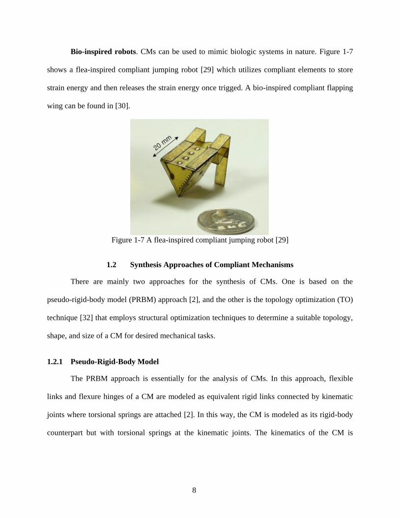
Bio-inspired robots. CMs can be used to mimic biologic systems in nature. Figure 1-7
shows a flea-inspired compliant jumping robot [29] which utilizes compliant elements to store
strain energy and then releases the strain energy once trigged. A bio-inspired compliant flapping
wing can be found in [30].
Figure 1-7 A flea-inspired compliant jumping robot [29]
1.2 Synthesis Approaches of Compliant Mechanisms
There are mainly two approaches for the synthesis of CMs. One is based on the
pseudo-rigid-body model (PRBM) approach [2], and the other is the topology optimization (TO)
technique [32] that employs structural optimization techniques to determine a suitable topology,
shape, and size of a CM for desired mechanical tasks.
1.2.1 Pseudo-Rigid-Body Model
The PRBM approach is essentially for the analysis of CMs. In this approach, flexible
links and flexure hinges of a CM are modeled as equivalent rigid links connected by kinematic
joints where torsional springs are attached [2]. In this way, the CM is modeled as its rigid-body
counterpart but with torsional springs at the kinematic joints. The kinematics of the CM is

9
equivalent to that of its rigid-body counterpart, and the compliance of the CM is represented by
the torsional springs.
Figure 1-8 (a) Cantilever beam with a flexure hinge and (b) its PRBM
Figure 1-8 shows a cantilever beam with a flexure hinge and its PRBM. The motion of
the beam mainly results from the deflection of the flexure hinge. In the PRBM approach, the
flexure hinge is modeled as a pin joint and the compliance of the flexure hinge is represented
through a torsional spring of stiffness 𝐾𝑠. Note that the location of the pin joint and the stiffness
of the torsional spring are the key factors for accurate modelling. The PRBMs for other
compliant segments in CMs refer to [2].
The synthesis of CMs based on the PRBM approach consists of two major classes:
rigid-body replacement synthesis and synthesis with compliance. The rigid-body replacement
synthesis is a two-step approach. First, an appropriate PRBM for a CM for desired kinematic
tasks is determined. In this step, the type of the mechanism is assumed, e.g., a four-bar
mechanism, but the lengths of links and locations of pin joints are adjustable (design variables).
Second, the PRBM is directly converted to a CM by considering the stress or input requirements.
In this step, many different CMs may be generated from one PRBM [2]. If the energy storage is
𝑙/2
𝑙
(a)
(b)
Torsional spring 𝐾𝑠
Pin joint

10
also concerned in the synthesis of CMs, besides the lengths of links and locations of pin joints,
the stiffness values of torsional springs are also the design variables to be determined. In this
case, it is called synthesis with compliance.
The PRBM approach takes advantage of the knowledge in the kinematics of RBMs and
thus provides designers with an intuitive and efficient tool for the analysis and synthesis of CMs.
However, with the PRBM approach, a designer needs to start from a given mechanism type, such
as a four-bar or a five-bar mechanism, which may thus limit the scope of candidate designs for
the best performance.
1.2.2 Topology Optimization
TO is to determine a suitable topology, shape, and size of a CM for desired mechanical
tasks based on structural optimization techniques. The term “topology” here for CMs, similar
with the term “type” for RBMs, includes the number of links and joints, the types of joints, the
connectivity of links and joints, input and their locations, and boundaries with respect to the
environment (ground in mechanism theory) [33, 34]. For example, although the four mechanisms
shown in Figure 1-1 all have four links (including the ground link), they represent four different
topologies due to the different types of links and joints they have. Another example is given in
Figure 1-9 where the link connectivity (solid black lines) among the four points (black squares)
determines the topology of the CMs in a space (dashed quadrilaterals). Those in Figure 1-9a, b,
and c represent CMs of different topologies. However, those in Figure 1-9a and d have the same
topology but with different geometries particularly with different locations of the connection
point and the in-plane widths of the links.

11
Figure 1-9 Understanding mechanism topologies
TO has been developed originally for the synthesis of load-bearing structures. A structure
is an assembly of parts, which is intended to sustain loads [35]. Motion is undesirable in a
structure. TO for structures is to determine the material or “part” distribution (or link
connectivity) in a given design domain (i.e., the space where the final structure should locate) to
achieve maximum stiffness, given the amount of materials or “parts” and boundary conditions.
Comprehensive reviews on the TO for structures are given in [36, 37].
To design CMs using TO, the function requirements on mechanisms such as output
displacements must be considered. Thus, TO for CMs determines the material or “part”
distribution (or link connectivity) in a given design domain so that the CM formed by the
distributed material fulfills the functional requirements [38]. The significance of TO lies in the
fact that the choice of appropriate topology of a structure or a CM in the design process is the
most decisive factor (and often difficult) for the efficient design of novel products [37]. TO for
the synthesis of CMs automates the design process and does not require a given/initial
mechanism topology but gives topologically optimized results. This feature is the main
advantage of the TO compared with the PRBM approach which requires a given mechanism type
or topology. In this dissertation, the focus is on the TO of CMs.
(a) (b)
(c) (d)

12
TO is a highly integrated systematic approach for structural synthesis, and it involves
four aspects: parameterization of design domains, optimization formulations, optimization
algorithms, and finite element analysis. The parameterization of a design domain consists of the
discretization of the domain and the definitions of design variables. A design domain is first
discretized into discrete units. Then, design variables which are related to the physical
parameters of those units such as material density [39] or cross-sectional area [40] are assigned
to these units. By determining the values of the design variables and thus the states of those units
(removed or kept), the topology and geometry of a CM can be determined. Optimization
formulations, including objective functions and constraints, are formulated to represent the
design criteria (functional requirements and constraints). Together with mechanism evaluations
based on the finite element analysis, an optimization algorithm is used to find the optimal values
of the design variables and hence to give optimized topologies. In the following, TO for
structures and TO for CMs are briefly introduced, respectively, to facilitate the subsequent
discussions particularly related to the motivations and objectives of the study in this dissertation.
Topology optimization for structures. The optimal design problem for structure
synthesis, as depicted in Figure 1-10, is to find the optimal choice of the stiffness tensor 𝐸𝑖𝑗𝑘𝑙(𝑥)
which is a design variable throughout a given design domain Ω (the grey area) to achieve
maximum stiffness of the overall structure along the direction of loading, given the amount of
materials and boundary conditions (loads and supports) [32]. This is essentially to find the layout
of the structure which occupies a domain Ωs (a subset of design domain Ω).

13
Figure 1-10 Structure design problem
For given external forces, the maximum stiffness of a structure indicates the minimum
work done by the external forces (assuming small deformation and thus linear force-deflection
relationship). The load linear form and the energy bilinear form are 𝑙(𝑢) = ∫ 𝑏𝑢 𝑑𝛺𝛺
+
∫ 𝑓𝑢 𝑑ГГ
and 𝑎(𝑢, 𝑣) = ∫ 𝐸𝑖𝑗𝑘𝑙(𝑥)휀𝑖𝑗(𝑢)휀𝑘𝑙(𝑣)𝑑𝛺𝛺, respectively, where 𝑙(𝑢) is the external
work done by body force 𝑏 and surface force 𝑓 on an elastic body which is at equilibrium 𝑢
(the displacement field due to 𝑏 and 𝑓) and 𝑎(𝑢, 𝑣) is the internal virtual work of an elastic
body at equilibrium 𝑢 with a virtual displacement 𝑣 [32].
To achieve the goal of the maximum stiffness, the external work done by the specified
external forces should be minimized. The optimal design problem [32] is thus
to find 𝐸𝑖𝑗𝑘𝑙(𝑥) to minimize 𝑙(𝑢),
subject to 𝑎(𝑢, 𝑣) = 𝑙(𝑣) and ∫ 1𝑑ΩΩs
≤ 𝑉∗, (1.1)
where 𝑎(𝑢, 𝑣) = 𝑙(𝑣) is the equilibrium Equation based on the principle of virtual power and
𝑉∗ is the maximum amount of material allowed (“1” represents the presence of material in the
domain Ωs, and other regions in the design domain Ω have no material, denoted with “0”).
Equation (1.1) is the general form of TO for structure synthesis. The design problem is
solved based on the finite element method which discretizes the design domain Ω with elements.
The discrete form of Equation (1.1) is
Load
Support Design domain Ω
Ωs ?

14
to find 𝑬𝒆 to minimize 𝐅𝑇𝐔,
subject to K(𝑬𝒆) 𝐔= 𝐅 and ∑𝑣𝑒 ≤ 𝑉∗, (1.2)
where 𝐅 and 𝐔 are the nodal external force vector and nodal displacement vector, respectively.
𝐅𝑇𝐔 indicates the strain energy stored in the elastic body. 𝑬𝒆 and 𝑣𝑒 represent the elasticity
matrix and material volume of each finite element e (e=1,2…N, N is the number of elements),
respectively. 𝐸𝑖𝑗𝑘𝑙(𝑥) is assumed to be constant, 𝑬𝒆, throughout the body of each element. Now
𝑬𝒆 is the design variable for each element. K(𝑬𝒆) is the assembly of the global stiffness matrice
𝑲𝑒(𝑬𝒆) of all the finite elements: K=∑𝑲𝑒(𝑬𝒆).
A design domain is discretized into a mesh of finite elements or discrete units. By
determining which units to keep and which to remove, one gets a specific stiffness matrix K that
actually represents the material distribution. Two commonly used discretization schemes are the
continuum approach and the ground structure approach. The continuum approach completely
fills the design domain using polygonal elements such as quadrilateral elements (shown in Figure
1-11a) and hexagonal elements [41]. The ground structure approach utilizes a network of truss or
beam elements (shown in Figure 1-11b) to represent the design domain which is only partially
occupied.
Figure 1-11 Two commonly used discretization approaches: (a) continuum discretization with
quadrilateral finite elements and (b) ground structure with beam or truss elements
(a) (b)

15
Each element 𝑒 is assigned with a variable 𝜌𝑒 which represents the presence (𝜌𝑒 = 1,
solid state) or absence (𝜌𝑒 = 0, void state) of the element. The stiffness property of the element
is
𝑬𝒆 = 𝜌𝑒𝑬∗, 𝜌𝑒 = {
1, if element 𝑒 is present (solid),
0, if element 𝑒 is absent (void), (1.3)
where 𝑬∗ is the finite element elasticity matrix of the given material in its solid state. Thus, the
material distribution problem is essentially a discrete 0-1 problem.
The most widely used approach for this discrete 0-1 problem is to change it into a
continuous problem: 𝜌𝑒 becomes continuous between 0 and 1. With this treatment, the use of
gradient-based optimization algorithms becomes possible and the design problem becomes a
sizing problem. If the ground structure approach is used, 𝜌𝑒 can be interpreted as the
cross-sectional area of truss elements or in-plane width of beam elements. Different values
between 0 and 1, intermediate values, represents different cross-sectional areas or in-plane width.
However, if the continuum discretization approach is used, the continuous form of 𝜌𝑒 may lead
to elements with undesirable intermediate values since ρ𝑒 now represents the relative density of
material. “𝜌𝑒=0” means no material exists and “𝜌𝑒=1” the solid material exists, while an
intermediate value (for example, 𝜌𝑒=0.5) is not practical. Thus, a penalization scheme may be
used to penalize intermediate values. An efficient penalty approach is the Solid Isotropic
Material with Penalization (SIMP) approach which is as follows:
𝑬𝒆 = 𝜌𝑒𝑝𝑬∗, 𝑝 > 1, 0 < ρ𝑚𝑖𝑛 ≤ ρ𝑒 ≤ 1,∑ ρ𝑒v
0 ≤𝑉∗, (1.4)
In the above equation, where the power index 𝑝 penalizes the intermediate value and
pushes it to the extreme values 0 or 1. Note that the “0” is usually represented by a small value
𝜌𝑚𝑖𝑛. This treatment is to avoid the singularity of the stiffness matrix K.) 𝜌𝑒v0 is the material
volume occupied by element e. With a limited source of material, TO tends to economically use

16
material for maximum stiffness instead of consuming materials on the elements of intermediate
values. The Equation (1.2) now becomes
to find 𝜌𝑒 to minimize 𝐅𝑇𝐔,
subject to K(𝜌𝑒) 𝐔= 𝐅 and ∑𝜌𝑒 𝑣0 ≤ 𝑉∗, (1.5)
where K(𝜌𝑒)=∑𝜌𝑒𝑝𝑲𝑒∗ , 𝑲𝑒
∗ is the global stiffness matrix of element e in its solid state (𝜌𝑒 = 1).
To solve the design problem in Equation (1.5) using the gradient-based optimization
algorithm, sensitivity (gradient) analysis is necessary. The key point here is to derive the
derivative of 𝐔 with respect to design variables 𝜌𝑒 (The detailed derivation can be found in
[32]). Once the derivatives of the objective function and the constraints with respect to the design
variables are obtained, one can apply a nonlinear optimization solver such as Sequential Linear
Programming (SLP), Sequential Quadratic Programming (SQP), and Method of Moving
Asymptotes (MMA) [42]. MMA is recommended since it is versatile and efficient for large scale
TO problems. The code of MMA may be obtained by contacting Professor Krister Svanberg at
KTH Royal Institute of Technology. An example of the structure design with TO based on the
continuum discretization of the design domain for the design problem of Figure 1-10 is shown in
Figure 1-12.
Figure 1-12 A structure design example based on continuum discretization
Topology optimization for compliant mechanisms. Mobility of CMs distinguishes a
CM from a structure. A structure is designed to support external loads with minimum
Load
Support

17
deformation while a CM is designed to deliver output displacements via deformation of the
material of CM (i.e., the flexibility of the system in this case). Thus, flexibility is a significant
factor for the mobility of CMs. In addition, a CM also needs to be stiff enough to resist external
loads. Therefore, the optimal design of CMs has two conflicting design criteria: (1) be flexible
enough to deliver output displacement; and (2) be stiff enough to support external loads. Any
formulation with the simultaneous considerations of both criteria is the so-called
stiffness-flexibility multi-criteria formulation. Many multi-criteria formulations have been
developed, such as the ratio form of mutual strain energy (MSE) and strain energy (SE) [40, 43],
Mechanical Advantage (MA), Geometric Advantage (GA), and Mechanical Efficiency (ME) [44,
45]. Although those formulations are different in forms, they are essentially similar. In the
following, the ratio form of MSE and SE is discussed in detail.
The SE of a CM is the same as the measure for the optimal design of the structure.
Simply speaking, MSE is numerically equal to the output displacement [46]. Thus, by
maximizing the ratio of MSE and SE, both the output displacement and the stiffness can be
maximized, which meets the stiffness-flexibility criterion above.
A design domain with specified loads and boundary conditions is shown in Figure 1-13.
A spring with stiffness of 𝑘𝑠 at the output port is attached to the output port to represent the
reaction force from the environment (e.g., work-piece) with which the CM interacts.
Figure 1-13 CM design problem
Input force
Support
Ωs?
ks
Design domain Ω

18
The way to calculate the output deformation is as follows. Suppose that a unit dummy
force 𝑝𝑑 is first applied at the output port in the direction of the desired deformation; then, the
input force is applied. During the loading process of the input force, the work done by the
dummy force is MSE as calculated by
𝑝𝑑∆𝑜𝑢𝑡= |∆𝑜𝑢𝑡| = ∫ 𝜎𝑑𝑇휀𝑑𝛺′
𝛺′, (1.6)
where Ω′ represents the combination of the design domain Ω and the spring, and 𝜎𝑑 is the
stress field when only the unit dummy load is applied. 휀 and ∆𝑜𝑢𝑡 are the strain field and
output displacement when only the input force is applied, respectively. The strain energy, SE, is
SE=1
2∫ 𝜎𝑇휀𝑑𝛺′𝛺′
, (1.7)
where 𝜎 is the stress field when only the input force is applied.
Linear finite element method is employed to calculate MSE and SE. The equilibrium
equation when only input force is applied is
KU=F, (1.8)
where K is the combination of the global stiffness matrices of the structure and the spring,
and F is the nodal force vector consisting of the input force, and U is the nodal displacement
vector due to the input force.
The equilibrium equation when only the unit dummy force is applied is
KV=𝑭𝒅, (1.9)
where 𝐅𝒅 is the nodal force vector consisting of unit dummy force 𝑝𝑑, and V is the nodal
displacement vector due to the dummy force. The MSE and SE can be computed by
MSE=𝐕𝑇𝑲𝐔,
SE=𝟏
𝟐𝐔𝑇𝑲𝐔. (1.10)

19
The CM design problem is
to find 𝜌𝑒 to maximize 𝑀𝑆𝐸/𝑆𝐸,
subject to K(𝜌𝑒) 𝐔= 𝐅, K(𝜌𝑒)V=𝐅𝒅, and ∑ρ𝑒 ≤ 𝑉∗. (1.11)
Procedures (sensitivity analysis and optimization algorithm) to solve the problem in
Equation(1.11) are similar with those of structure design and are not detailed. Two compliant
displacement inverters designed using the continuum approach and ground structure approach,
respectively, are shown in Figure 1-14.
Figure 1-14 Compliant displacement inverters designed through (a) the continuum approach and
(b) the ground structure approach
1.3 Motivation and Objective
This dissertation is devoted to developing TO techniques for the synthesis of CMs. In this
section, the motivations of the work are outlined, followed by the research objectives. Detailed
descriptions on each motivation can be found in the “Introduction” section of each manuscript,
accordingly. A comprehensive review on the relevant issues in the literature is presented in
Chapter 2 and Chapter 3, respectively.
(a) (b)

20
1.3.1 Research Motivation
The first motivation is from the fact that a CM needs to be efficient in transferring motion,
force, or energy and meanwhile strong to resist yield or fatigue failure. In the literature, the main
focus of this field was on formulating the stiffness-flexibility criterion into optimization
formulations [2, 40, 43-45, 47, 48]. These formulations are essentially similar—all seeking to
maximize the force, motion, or energy transfer capabilities of CMs; thus, they all result in
lumped CMs which are generally more efficient in transferring force, motion, or energy than
distributed CMs. However, a lumped CM is locally stressed (with higher stress levels) and thus
weaker to resist yield or fatigue failure than its distributed counterparts. Therefore, some studies
[49-53] have attempted to develop TO for distributed CMs. A distributed CM generally has
lower stress levels and but lower efficiency than its lumped counterpart. To optimize the design
of CMs (which are both efficient and strong) is the first motivation of this dissertation.
The second motivation originates from the comparisons between the CM and structure. In
the literature, except for the objective functions, all other TO procedures for CMs are basically
the same as those for structures. However, in fact, there are at least three aspects that make a CM
significantly different from a structure: functional requirements, joints, and types of actuations.
First, the main goal of the structure is to be stiff enough to support the external load; however,
the typical functional requirements of mechanisms are (1) function generation, (2) path
generation, and (3) motion generation [54]. Second, the concept of joints in mechanisms is
highly important because joints are the source of the mobility of a mechanism. However, for a
structure, the concept of joint is not important as long as the structure is stiff and stable. Third, a
CM can be driven by different types of input motions such as translational motion or rotary
motion depending on applications while a structure only needs to sustain external loads such as
self-weight. Thus, the second motivation of this dissertation is to develop an improved design

21
procedure along with theories for CMs more from a mechanism perspective particularly with the
foregoing three differences between the mechanism and structure.
1.3.2 Research Objective
The research objectives based on the motivations are as follows:
(1) Objective 1: To understand the formulation of the design problem of TO for CMs. General
problems associated with the design of CMs through TO are to be defined. Standard design
problems associated with rigid body mechanisms, i.e. function generation, path generation,
and motion generation, will be extended to CMs. Functional requirements and associated
formulations in the literature are comprehensively reviewed along with their limitations.
(2) Objective 2: To develop TO for the design of CMs which are efficient in transferring
motion, force, or energy and meanwhile strong to resist yield failure. Components of
distributed compliance (beams) and those of lumped compliance (flexure hinges) are to be
integrated into TO; meanwhile, a new design criteria for the purpose of strong CMs is to be
formulated into optimization objective functions.
(3) Objective 3: To develop TO for the design of CMs for motion generation. Given design
specifications such as the design domain and boundary conditions, a CM is to be
determined to guide a flexible link into desired configurations.
(4) Objective 4: To develop TO for the integrated design of CMs and actuators for motion
generation. The locations of actuators are to be simultaneously determined with the
determination of the CM structure. Bending actuators and rotary actuators are to be
considered.

22
(5) Objective 5: To develop TO for the design of CMs with the consideration of joints. The
connection between links will not be assumed rigid any more. Instead, a joint could be a
pin joint (PJ), compliant joint (CJ), or rigid joint (RJ).
1.4 Organization of the Dissertation
The presentation of this dissertation takes a manuscript style. The dissertation consists of
an introduction chapter (Chapter 1), six body chapters (Chapter 2~7), and a conclusion chapter
(Chapter 8). Each body chapter consists of a manuscript published or accepted for publication or
submitted under review. At the beginning of each manuscript, a brief introduction is included to
describe the connection of the manuscript to the context of the thesis. All manuscripts have been
formatted to be consistent throughout the dissertation. A brief introduction to each chapter is
provided below.
Chapter 1 introduces the backgrounds, motivations, and objectives of this dissertation.
Chapter 2 presents a comprehensive review on TO techniques for CM design on six
topics: (1) design problems and optimization formulations; (2) lumped CMs and distributed CMs;
(3) parameterization approaches; (4) large-displacement CMs; (5) integrated design of CMs and
actuators; (6) optimization algorithms. This review also motivates the objectives of the studies in
the dissertation.
Chapter 3 presents the study for Objective 1. General problems associated with the
design of CMs through TO techniques are defined due to the lack of comprehensive definitions
for these problems in the literature. Standard design problems associated with rigid body
mechanisms, i.e., function generation, path generation, and motion generation, are extended to
CMs. Functional requirements and 25 formulations in the literature are comprehensively
reviewed along with the discussion of their limitations. Based on whether the output is controlled

23
quantitatively or not, these formulations are categorized into two types: (1) formulations for
quantitative design and (2) formulations for qualitative design. In addition, formulations that aim
to solve the point flexure problem are also discussed. Future work is recommended with respect
to the discussion on each topic.
Chapter 4 and Chapter 5 present the studies for Objective 2. Specifically, in Chapter 4,
the concept of hybrid CMs is highlighted. Hybrid CMs provide a way to integrate lumped
compliance of flexure hinges and distributed compliance of beams together for better
performance. Chapter 4 proposes a framework for the systematic analysis and synthesis of hybrid
CMs. In this framework, a new type of finite element, i.e., super flexure hinge element, is
incorporated with the classical beam elements to mesh design domains, leading to a new TO
technique for hybrid CM design. Based on the work presented in Chapter 4, an input stroke
design criterion is proposed in Chapter 5 for the purpose of efficient and strong CMs. Further, in
this chapter, an input stroke metric based on the von-Mises yield criterion is defined and
formulated into the objective function of the TO of CMs. It is in this chapter (Chapter 5), both
the parameterization and formulation in TO are carefully developed to facilitate the integration
of lumped compliance and distributed compliance and eventually this leads to efficient and
strong CMs.
Chapter 6 presents the studies for Objective 3 and Objective 4. In Chapter 6, a
systematic approach for the integrated design of CMs and actuators for motion generation is
presented. Both rotary actuators and bending actuators are considered. The approach
simultaneously synthesizes the optimal structural topology and the actuator placement for
desired position, orientation, and shape of a target link in the system, while satisfying the
constraints such as buckling constraint, yield stress constraint and valid connectivity constraint.

24
The approach has the following key features: (1) the use of bending actuator and rotary actuator
as the actuation of CMs, (2) the simultaneous optimization of the location and orientation of the
actuator concurrent with the topology of the CM, (3) the implementation of guiding a flexible
link through the initial and desired configurations, including precision positions, orientations,
and shapes, and (4) a new valid connectivity scheme to check whether a design has valid
connectivity among the regions of interest based on the concept of the directed graph.
Chapter 7 presents the study for Objective 5. Chapter 7 proposes the analysis models and
synthesis approach which are appropriate for both RBMs and CMs. The concept of a
modularized mechanism is proposed to generally represent RBMs and CMs in an unified way.
Compliant link (CL), rigid rink (RL), pin joint (PJ), compliant joint (PJ), and rigid joint (RJ) are
the five basic modules. The finite element models of modularized mechanisms are developed
based on a new beam-hinge model. The model can conveniently describe the five modules and
allow for the specification of rotational input or output motion. Based on the concept of
modularized mechanisms and the beam-hinge model, a link and joint determination approach,
module optimization, is developed for the type and dimension synthesis of RBMs and CMs
together. The states (existence and sizes) of joints and those of links are all considered as design
variables. With module optimization, one may obtain a RBM, or a partially CM, or a fully CM
for a given mechanical task.
Chapter 8 concludes the dissertation and summarizes the contributions. Also, the
directions for future research are identified and discussed.
1.5 Contributions of the Primary Investigator
In this dissertation, all included manuscripts are co-authored. However, it is the mutual
understanding of all authors that Lin Cao, as the first author, is the primary investigator.

25
CHAPTER 2
TOPOLOGY OPTIMIZATION OF COMPLIANT MECHANISMS: STATE OF THE ART
This chapter presents a comprehensive review on TO for CMs, covering six topics. This
review sets a literature foundation for the motivations of this dissertation.
The work presented in this chapter is included in the following manuscript:
Cao, L., Dolovich, A., and Zhang, W. J., 2014, "Topology Optimization of Compliant
Mechanisms: State of the Art," Mechanical Science, submitted as Review Paper, under review,
manuscript ID: ms-2014-59.
Abstract
The most challenging part of CM design is the selection of a proper topology for the
desired mechanical tasks. TO techniques do not require a given/initial mechanism topology but
gives topologically optimized designs; thus, substantial efforts of research have been devoted to
developing TO techniques for CM design. This paper presents a comprehensive review on TO
techniques for CM design on six topics: (1) design problems and optimization formulations; (2)
lumped CMs and distributed CMs; (3) parameterization approaches; (4) large-displacement CMs;
(5) integrated design of CMs and actuators; (6) optimization algorithms. Future research
directions are also discussed on each of these topics.
2.1 Introduction
A CM is a mechanism that obtains at least some of its mobility from the deformation of
its flexible components [2]. Using CMs as solutions to mechanical tasks may lead to advantages
such as reduced cost (reduced parts, reduced assembly time, and simplified fabrication process)

26
and improved performances (improved precision, improved reliability, less wear, less weight,
and less maintenance). CMs have attracted numerous attentions in recent years due to these
advantages and have been utilized in various applications such as precision stages [15, 18, 19],
MEMS [14, 20-23], and biomedical devices [24-26].
The most challenging part of CM design is the selection of a proper topology for desired
mechanical tasks. A systematic design approach for CMs without the need of the initial topology
is TO [32]. TO is developed originally for the synthesis of load-bearing structures. A structure is
an assembly of material that is intended to sustain loads [35] with motion being undesirable. TO
for the structure is thus to determine the material distribution in a given design domain (the space
where the final structure should locate) to achieve a maximum stiffness given the amount of
material allowed to occupy the design domain and boundary conditions. Some excellent reviews
on TO for the structure may refer to [36, 37]. When TO is tailored to the design of CMs, the
function requirements and constraints such as output displacements need to be considered. Thus,
TO for CMs is to determine the material distribution in a design domain such that the formed
CM fulfills these function requirements and constraints [38].
The significance of TO lies in the fact that the selection of a proper topology of the
structure or CM is of no need, so the subjectivity in both designs of the structure and mechanism
is reduced. Note that the selection of an initial topology to start with design, a very traditional
thinking in rigid body mechanism design, is a difficult task and notoriously called type synthesis
[55]. TO for the synthesis of CMs or structures thus significantly automates the design process
and gives topologically optimized designs. TO is therefore the most efficient technique for the
synthesis of CMs or structures from this perspective.

27
TO is a highly integrated systematic approach for structural synthesis, and it involves
four aspects: parameterization of design domains, optimization formulations, optimization
algorithms, and finite element analysis. The parameterization of a design domain consists of the
discretization of a domain and the definitions of design variables. A design domain is first
discretized into discrete units. Then, design variables which are related to the physical
parameters of these units such as material density [39] or cross-sectional area [40] are taken as a
surrogate of these units. By determining the values of the design variables and thus the states of
these units: removed or kept and even the sizes, the topology and geometry of a CM can be
determined. Optimization formulations, including objective functions and constraints, are
formulated to represent design criteria (function requirements and constraints). Together with the
evaluation of designs in progress or evolving with finite element analysis, an optimization
algorithm can be taken to find the optimal values of the design variables, which in fact give the
optimized topologies.
In 1994, Ananthasuresh [38] initiated the TO technique for the design of CMs. In the past
two decades, many studies have further advanced TO techniques for the design of CMs [32, 40,
41, 44, 45, 47-49, 51, 53, 56-75]. A variety of problems have been addressed, such as more
complex parameterization schemes, different design problems and formulations, geometric
nonlinearity, integrated designs of the mechanism structure and actuator, and the use of genetic
algorithms as an optimization solver. There are two review papers [48, 76] on TO for CMs, but
their topics are limited to the CM design problems or optimization formulations only. The
present paper presents a critical comprehensive review on six essential topics: (1) design
problems and optimization formulations; (2) lumped CMs and distributed CMs; (3)
parameterization approaches; (4) large-displacement CMs; (5) integrated design of CMs and

28
actuators; and (6) optimization algorithms. Future research directions are also discussed on each
of these topics.
The present paper is organized as follows: In Section 2.2, backgrounds on the categories
of CMs, TO for structures, and TO for CMs are presented. Section 2.3 presents a critical review
of TO for CM design. Studies on the aforementioned six topics are reviewed and commented,
and future research directions are thus derived. Section 2.4 concludes the paper.
2.2 Background
2.2.1 Categories of Compliant Mechanisms
Fully CMs and partially CMs. CMs can be categorized into partially CMs and fully
CMs, depending on whether all the mobility of the CM comes from the deformation of flexible
components. A partially CM has both kinematic pairs (such as pin joints) and flexible
components, and its motion is a combination of the motion permitted by the kinematic pairs and
the deformation of the flexible components. A fully CM does not have any kinematic pair, and
its motion is attributed to the deformation of flexible components only. The CMs in Figure 2-1b
and c are both fully CMs while the CM in Figure 2-1d is a partially CM which consists of not
only flexure hinges and flexible links, but also pin joints. The motion of the partially CM
consists of the rotation permitted by the pin joints and the deformation at the slender links and
flexure hinges. A fully CM is usually manufactured as a single piece of material (monolithic
structure).
Lumped CMs and distributed CMs. CMs are also categorized into lumped CMs and
distributed CMs, depending on where the deformation comes from in the CM. If the deformation
comes from localized regions, the CM has lumped compliance (or localized compliance) and is a
lumped CM. In contrast, if the deformation does not come from localized regions but broader

29
regions, the CM has distributed compliance and is a distributed CM. The CM shown in Figure
2-1b is a lumped CM because the deformation is localized at the flexure hinges that mimic pin
joints. In contrast, Figure 2-1c shows a distributed CM where the deformation is more evenly
distributed on the slender links (broader regions). There is no relative rotation between the
connected links; thus the links are considered as rigidly connected through rigid joints.
Commonly used flexure hinges are notch flexure hinges that have regions of abruptly
reduced cross sections. A notch flexure hinge generally is prone to high stress and stress
concentration and thus limits the motion range and fatigue life of the mechanism. Thus, a lumped
CM generally has higher stress and short motion range than its distributed counterparts. However,
a distributed CM may cost more energy to deform since it has more or lager deformed regions
than its lumped counterparts. Thus, a lumped CM is able to transfer more energy to the output
port and thus more energy efficient than its distributed counterparts. Some durable
large-displacement flexure hinges with complex structures refer to [3-9].
Figure 2-1 Four types of four-bar mechanisms: (a) a four-bar RBM, (b) a four-bar lumped fully
CM, (c) a four-bar distributed fully CM, and (d) a four-bar partially CM
Rigid link Pin joint
Flexure hinge
Rigid joint
Compliant link
(a) (b)
(c) (d)

30
2.2.2 Topology Optimization for Structures
The optimal design problem for structure synthesis, as depicted in Figure 2-2, is to find
the optimal choice of the stiffness tensor 𝐸𝑖𝑗𝑘𝑙(𝑥) that is a design variable throughout a given
design domain Ω (the grey area) to achieve the maximum stiffness, given the amount of material
allowed to occupy the design domain and boundary conditions (loads and supports). This is
essentially to find the layout of the structure that occupies a domain Ωs (a subset of the design
domain Ω) [32].
Figure 2-2 Structure design problem
Given external forces, the maximum stiffness of a structure means the minimum work
done by the external forces (assuming the small deformation and thus linear force-deflection
relationship). The linear form of load and the bilinear form of energy are 𝑙(𝑢) = ∫ 𝑏𝑢 𝑑Ω𝛺
+
∫ 𝑓𝑢 𝑑ГГ
and 𝑎(𝑢, 𝑣) = ∫ 𝐸𝑖𝑗𝑘𝑙(𝑥)휀𝑖𝑗(𝑢)휀𝑘𝑙(𝑣)𝑑𝛺𝛺, respectively, where 𝑙(𝑢) is the external
work done by body force 𝑏 and surface force 𝑓 on an elastic body at equilibrium 𝑢 (the
displacement field due to 𝑏 and 𝑓, respectively) and 𝑎(𝑢, 𝑣) is the internal virtual work of the
elastic body at equilibrium 𝑢 with a virtual displacement 𝑣 [32].
To achieve the maximum stiffness, the external work done by specified external forces is
minimized. The optimal design problem [32] is:
to find 𝐸𝑖𝑗𝑘𝑙(𝑥) to minimize 𝑙(𝑢),
Load
Support Design domain Ω
Ωs ?

31
subject to 𝑎(𝑢, 𝑣) = 𝑙(𝑣) and ∫ 1𝑑ΩΩs
≤ 𝑉∗, (2.1)
where 𝑎(𝑢, 𝑣) = 𝑙(𝑣) is the equilibrium equation based on the principle of virtual power and
𝑉∗ is the maximum allowed amount of material (“1” represents the presence of material in the
domain Ωs, other regions in the design domain Ω have no material, denoted by “0”).
Equation (2.1) is the general form of TO for structure synthesis. The design problem is
solved with a finite element method that discretizes the design domain Ω with finite elements.
The mesh that defines the design variable 𝐸𝑖𝑗𝑘𝑙(𝑥) and the mesh that defines the displacement
field 𝑢 are usually the same but they can also be different. In this paper, we assume that the
same mesh is used for simplicity. The discrete form of Equation (2.1) is:
to find 𝑬𝒆 to minimize 𝐅𝑇𝐔,
subject to K(𝑬𝒆) 𝐔= 𝐅 and ∑v𝑒 ≤ 𝑉∗, (2.2)
where 𝐅 and 𝐔 are the nodal external force vector and nodal displacement vector, respectively.
𝐅𝑇𝐔 indicates the strain energy stored in the elastic body. 𝑬𝒆 and v𝑒 represent the elasticity
matrix and material volume of each finite element e (e=1, 2…N, N is the number of elements),
respectively. 𝐸𝑖𝑗𝑘𝑙(𝑥) is assumed to be constant, 𝑬𝒆, throughout the body of each element. Now
𝑬𝒆 is the design variable for each element. K(𝑬𝒆) is the assembly of the global stiffness matrice
𝑲𝑒(𝑬𝒆) of all the finite elements: K=∑𝑲𝑒(𝑬𝒆).
A design domain is discretized into a mesh with many finite elements or discrete units.
By determining which units to keep and which to remove, one gets a specific stiffness matrix K
or material distribution. Two commonly used discretization schemes are the continuum approach
and the ground structure approach. The continuum approach completely fills the design domain
using polygonal elements such as quadrilateral elements (shown in Figure 2-3a) and hexagonal

32
elements [41]. The ground structure approach utilizes a network of truss or beam elements
(shown in Figure 2-3b) to represent the design domain which is only partially occupied.
Each element 𝑒 is assigned with a variable 𝜌𝑒 which represents the presence (𝜌𝑒 = 1,
solid state) or absence (𝜌𝑒 = 0, void state) of the element. The stiffness property of the element
is:
𝑬𝒆 = 𝜌𝑒𝑬∗, 𝜌𝑒 = {
1, if element 𝑒 is present (solid),
0, if element 𝑒 is absent (void), (2.3)
where 𝑬∗ is the finite element elasticity matrix of the given material in its solid state. Thus, the
material distribution problem is essentially a discrete 0-1 problem.
Figure 2-3 Two commonly used discretization approaches: (a) continuum discretization with
quadrilateral finite elements and (b) ground structure with beam or truss elements
The most widely used approach for this discrete 0-1 problem is to change it into a
continuous problem: ρ𝑒 becomes continuous between 0 and 1. With this treatment, the use of
gradient-based optimization algorithms becomes possible and the design problem becomes a
sizing problem. If the ground structure approach is used, 𝜌𝑒 can be interpreted as the
cross-sectional area of truss elements or in-plane width of beam elements. Different values
between 0 and 1, intermediate values, represents different cross-sectional areas or in-plane width.
However, if the continuum discretization approach is used, the continuous form of ρ𝑒 may lead
to elements with undesirable intermediate values since 𝜌𝑒 now represents the relative density of
material. “𝜌𝑒 = 0” means no material exists and the solid material exists, while an intermediate
(a) (b)

33
value (for example, 𝜌𝑒 = 0.5) is not practical. Thus, a penalization scheme may be used to
penalize intermediate values. An efficient penalty approach is the SIMP approach for
intermediate densities:
𝑬𝒆 = 𝜌𝑒𝑝𝑬∗, 𝑝 > 1, 0 < 𝜌𝑚𝑖𝑛 ≤ 𝜌𝑒 ≤ 1,∑𝜌𝑒𝑣
0 ≤𝑉∗ (2.4)
where the power index 𝑝 penalizes intermediate values and pushes 𝜌𝑒 to the extreme values
𝜌𝑚𝑖𝑛 or 1. Note that 𝜌𝑚𝑖𝑛 is a small value which is close to zero, and it is used to avoid the
singularity of the stiffness matrix K. 𝜌𝑒v0 is the material volume occupied by element e. With a
limited source of material, TO tends to economically use materials for the maximum stiffness
instead of wasting materials on elements of intermediate values.
Equation (2.4) now becomes:
to find 𝜌𝑒 to minimize 𝐅𝑇𝐔,
subject to K(𝜌𝑒) 𝐔= 𝐅 and ∑ρ𝑒 v0 ≤ 𝑉∗, (2.5)
where K(𝜌𝑒)=∑𝜌𝑒𝑝𝑲𝑒∗ , 𝑲𝑒
∗ is the global stiffness matrix of element e in its solid state (𝜌𝑒 = 1).
To solve the design problem in Equation (2.5) using the gradient-based optimization
algorithm, sensitivity (gradient) analysis is necessary. The key point here is to derive the
derivative of 𝐔 with respect to design variables 𝜌𝑒 (the detailed derivation can be found in
[32]). Once the derivatives of the objective function and the constraints with respect to the design
variables are obtained, one can easily apply a nonlinear optimization solver such as SLP, SQP,
and MMA. MMA is recommended since it is versatile and efficient for large scale TO problem.
The code of MMA may be obtained by contacting Prof. Krister Svanberg at the KTH Royal
Institute of Technology. A structure design example based on the continuum discretization for
the design problem in Equation (2.5) is shown in Figure 2-4.

34
Figure 2-4 A structure design example based on continuum discretization
2.2.3 Topology Optimization for Compliant Mechanisms
Mobility of CMs distinguishes a CM from a structure. A structure is designed to support
external loads with minimum deformation while a CM is designed to flex and deliver output
displacement. Thus, flexibility is significant for mobility of CMs. In addition, a CM also needs to
be stiff enough to resist external loads. Therefore, the optimal design of CMs has two conflicting
design objectives: (1) be flexible enough to deliver output displacement; (2) be stiff enough to
support external loads. The formulations of TO for CMs should consider both objectives. Many
formulations have been developed by considering the two objectives. One widely used
multi-criteria formulation—MSE/SE—is introduced here. MSE and SE represent Mutual Strain
Energy [46] and Strain Energy, respectively.
SE of CMs is the same as the measure for optimal design of structure. MSE is
numerically equal to output deformation (will be detailed later). Thus, by maximizing the ratio of
MSE and SE, output deformation is maximized and the stiffness is maximized, which meets the
flexibility-stiffness criteria above.
Consider a design domain with specified loads and boundary conditions depicted in
Figure 2-5. A spring with stiffness of 𝑘𝑠 at the output port is attached to the output port to
model the reaction force from the work-piece (flexible) with which the CM interacts.
Load
Support
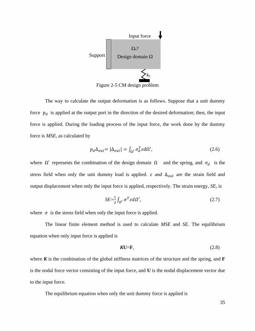
35
Figure 2-5 CM design problem
The way to calculate the output deformation is as follows. Suppose that a unit dummy
force 𝑝𝑑 is applied at the output port in the direction of the desired deformation; then, the input
force is applied. During the loading process of the input force, the work done by the dummy
force is MSE, as calculated by
𝑝𝑑∆𝑜𝑢𝑡= |∆𝑜𝑢𝑡| = ∫ 𝜎𝑑𝑇휀dΩ′
Ω′, (2.6)
where Ω′ represents the combination of the design domain Ω and the spring, and 𝜎𝑑 is the
stress field when only the unit dummy load is applied. 휀 and ∆𝑜𝑢𝑡 are the strain field and
output displacement when only the input force is applied, respectively. The strain energy, SE, is
SE=1
2∫ 𝜎𝑇휀𝑑𝛺′𝛺′
, (2.7)
where 𝜎 is the stress field when only the input force is applied.
The linear finite element method is used to calculate MSE and SE. The equilibrium
equation when only input force is applied is
KU=F, (2.8)
where K is the combination of the global stiffness matrices of the structure and the spring, and F
is the nodal force vector consisting of the input force, and U is the nodal displacement vector due
to the input force.
The equilibrium equation when only the unit dummy force is applied is
Input force
Support Design domain Ω
Ωs?
ks

36
KV=𝐅𝒅, (2.9)
where 𝐅𝒅 is the nodal force vector consisting of unit dummy force 𝑝𝑑, and V is the nodal
displacement vector due to the dummy force. The MSE and SE can be computed as
MSE=𝐕𝑇𝑲𝐔,
SE=𝟏
𝟐𝐔𝑇𝑲𝐔. (2.10)
The CM design problem is
to find 𝜌𝑒 to maximize MSE/SE,
subject to K(𝜌𝑒) 𝐔= 𝐅, K(𝜌𝑒)V=𝐅𝒅, and ∑𝜌𝑒 ≤ 𝑉∗. (2.11)
Procedures (sensitivity analysis and optimization algorithm) to solve the problem in
Equation (2.11) is similar with those in the TO formulation for the design of the structure and is
not detailed here. Two compliant displacement inverters design examples based on the
continuum approach and ground structure approach are shown in Figure 2-6.
Figure 2-6 Compliant displacement inverters designed through (a) the continuum approach and (b)
the ground structure approach
(a) (b)

37
2.3 Literature Review
2.3.1 Design Problems and Optimization Formulations
TO is originally developed for structure design, and the goal is to use a limited source of
materials to achieve maximum stiffness, given the design domain and boundary conditions. As
detailed in Section 2.1, the goal of maximum stiffness is formulated as the minimization of strain
energy (with specified input forces) in an elastic body. However, the main difference between
the CM and the structure is the mobility of the CM: a CM needs to be able to flex and deliver
output displacement while a structure does not. Thus, the first challenge of TO for CMs is to
formulate this function requirement into optimization formulations. Note that simply maximizing
the output displacement would lead to too flexible and invalid designs where no material is
distributed to connect the input and output ports to the specified displacement boundary supports.
The most widely used design problem formulation compromises between stiffness and flexibility.
Some studies also considered shape-morphing CM design and path-generating CM design.
Besides studies on the three design problems, studies on stress constraints are also discussed. The
review papers on design problem formulations can also be found in [48, 76].
Stiffness-flexibility. Ananthasuresh [38] made the first attempt to address this challenge.
Among many formulations he developed, one is the minimization of SE but with a spring
attached to the output port. The spring represents the flexible work-piece at the output port of the
CM. The formulation leads to stiff structures. However, the spring model provides a way to
account for the reaction force from the work-piece; moreover, the stiffness of the spring drives
the algorithm to distribute material at the output port, and the material connection between input
port and output port is therefore guaranteed. Noted that increasing the stiffness of the spring
often increases the stiffness at the output port [15]. Due to these features, the spring model is

38
widely used now but with different objective functions. Ananthasuresh [24] also developed a
multi-criteria formulation which minimizes the weighted linear combination of SE and MSE.
This multi-criteria (stiffness-flexibility) formulation aims to balance the stiffness and the
flexibility with a weighting factor. However, inappropriate weighting factors may lead to too
stiff CMs (stiff structures) or too flexible CMs (invalid connections).
The multi-criteria formulation for a balanced stiffness-flexibility property was then
extended by considering the ratio form of MSE and SE [40, 43], which does not require the
specification of weighting factors. Saxena and Ananthasuresh [56] replaced the MSE with the
output energy, 1
2𝑘𝑠 ∙ 𝑀𝑆𝐸
2, to maximize the energy delivered to the output port. Saxena and
Ananthasuresh [77] further generalized the multi-criteria formulation by defining the flexibility
requirement with an increasing function of the MSE, i.e., f(MSE), where ∂f/∂MSE > 0, and the
stiffness requirement an increasing function of SE, g(SE), where ∂g/∂SE > 0.
Instead of using the multi-criteria formulations, some researchers have emphasized the
direct uses of mechanical function requirements as objective functions. Sigmund [44] maximized
MA for the design of CMs. Lau et al. [45] directly employed MA, geometrical advantage, and
energy efficiency, respectively, as the objective functions. But these objective functions need an
extra upper-bounded constraint on either the input displacement or the output displacement to
ensure material connectivity among input/output port and displacement boundary supports.
Larsen et al. [78] minimized the least-squares errors between the obtained and prescribed values
of MA and geometrical advantage. This formulation allows designers to specify the desired MA
or geometrical advantage of CMs.
Note that with the specified input force and spring stiffness at output port, formulations
based on MA, geometrical advantage, and energy efficiency are basically similar (sometimes the

39
same) with the stiffness-flexibility formulations of ratio form. In addition, those formulations
often lead to lumped CMs or even CMs with undesirable point flexures (or de facto hinges) [48,
49, 64]. This problem has been a primary concern of the field. The topic on the problems of point
flexures, lumped compliance, and distributed compliance will be discussed in detail in Section
2.3.2.
Stress constraints. Stress distribution is another significant concern to CMs and
structures. TO for structures with stress constraints is briefly discussed here since CMs and
structures do not have a significant difference in this aspect. Two major challenges in dealing
stress constraints are (1) the “singularity” phenomenon and (2) the large number of constraints
due to the localized behavior of stress distribution [79-82]. The singularity phenomenon is about
the stress constraints on elements that are close to the lower bound (non-existing states). A
non-existing element may violate the stress constraint since its calculated stress appears to be
nonzero finite values. This phenomenon is referred to as a singularity because the stress of an
element appears to be nonzero value at the non-existing state [83]. To overcome this problem, a
relaxation approach is usually used to relax the stress constraints on elements approaching their
non-existing states [80, 81]. The second problem is that the stresses at all the elements should be
constraint, which results in too many local stress constraints in the optimization formulation, and
the sensitivity analysis for these constraints is costly in computation. A solution to this problem
is to introduce a global stress constraint for the whole structure rather than local stress constraint
for each finite element of the structure [79, 80]. The global stress constraint approximates the
maximum stress based on selected differentiable functions. However, the selection of appropriate
differentiable functions is a challenge.

40
Shape morph. Shape morph or shape change is related to the changes of the shapes of
mechanical compliant systems. Many systems such as aircraft wings and antenna reflectors need
to change their components’ shapes adaptively [84]. Lu and Kota [84] initiated the design of
shape morphing CMs using TO. Two different formulations—least square errors and a modified
Fourier transformation—were used to capture the difference between the desired shape and the
generated shape. The difference between the two formulations is that the former one includes not
only shape requirements but also dimension requirements while the latter one includes shape
requirements only. Including dimension requirements in the formulation may limit the potential
designs when the shape is the only concern in the design of shape-morphing CMs.
Path generation. Path generation is defined as the control of a point on a mechanism
such that it follows a prescribed path [85]. For path generating CMs, linear finite element
analysis is not sufficient since it assumes linear relationship between the input and output of a
CM, which is invalid in most path generating applications. Path generation is formulated as the
minimization of lest square errors between the generated path and the desired path. Studies on
path-generating CMs refer to [47, 63, 86-89], where the geometrical nonlinearity was considered.
Note that most of these studies used genetic algorithms instead of gradient-based
algorithms to solve the corresponding optimization problem. This is because the gradient-based
algorithm in this case requires sensitivity analysis with the geometrical nonlinearity being
considered, but genetic algorithm does not require sensitivity analysis. The topic on optimization
algorithms will be discussed in detail in Section 2.3.6.
Path generation is one of the three typical mechanism design problems known in RBMs.
The other two are function generation and motion generation. Discussion on the three design

41
problems for CM design refers to [76]. It is noted that neither function-generating CMs nor
motion-generating CMs have been studied in the field of TO for CMs.
2.3.2 Lumped Compliance and Distributed Compliance
This section first reviews studies on a problem called point-flexure in TO and then
studies on the lumped CMs and distributed CMs.
CM design based on the continuum discretization approach is prone to numerical
problems such as local minima, checkerboard pattern, mesh dependency, and point flexure. The
former three problems are also found in TO for the structure, and approaches to dealing with the
three problems can be found in [90]. Here we are interested in the point-flexure problem which is
encountered in TO for CMs only.
A point flexure is a local region with two solid quadrilateral elements connecting to each
other diagonally by only one node, as shown in Figure 2-7, highlighted with circles. Point
flexures are undesirable in CMs since they are impossible to be manufactured. A solution to this
problem is to replace point flexures with flexure hinges, which is a so-called post-processing
design [91]. However, behaviors of post-processed designs may greatly deviate from the original
intended designs [92]. Moreover, although replacements may be used, they may still suffer from
the high stress problem, which may lead to yield failure or fatigue failure.
Figure 2-7 Point flexures (circled regions) adapted from [48]
Point flexure

42
Studies [48, 49, 64] have shown that those stiffness-flexibility formulations are the main
causes of the point-flexure problem. Those formulations, although in different forms, mainly
have two objectives: maximizing output energy (flexibility criteria) and minimizing input energy
(stiffness criteria). The two objectives lead to designs with minimum strain energy stored in the
elastic bodies but maximum output energy. A best choice for the two objectives would be a
rigid-body linkage with revolute (pin) joints: no strain energy stored and energy transfer
efficiency is 100%. A point flexure is actually a pin joint through which connected links are free
to rotate (no moment transfer). The motion of a design with point flexures is mainly attributed to
the rigid-body rotation permitted by point flexures (no material deformation at point flexures).
Thus, designs with point flexures actually mimic rigid-body linkages, and they are found as
“optimal” choices, although impractical, by TO algorithms.
Avoiding point flexures in CMs or designing hinge-free CMs has been a primary concern
in the field of CM design. Two categories of strategies have been developed to avoid point
flexures in CMs: (1) one is based on the mechanical properties of point flexures, (2) and the
other is based on the geometric pattern of point flexures. Strategies in the first category aim to
design CMs where the mechanical properties of point flexures are unfavorable for a good design.
These strategies include restraining the relative rotation at every node [49], ensuring some extent
of strain energy stored in a CM using a new multi-criteria formulation [50] or a strain energy
maximization formulation (input is displacement) [52], limiting the local strain using a total
equivalent strain minimization formulation [51], and maximizing the characteristic stiffness at
the input and output ports [53]. Strategies in the second category directly expel the point-flexure
geometric pattern from designs. These strategies include using alternative parameterization (or
discretization) schemes [93-97] (more discussions refer to Section 2.3.3) and using a

43
differentiable constraint which mathematically describes the geometric pattern of point flexures
[98].
A point flexure is essentially a pin joint and an extreme case of lumped compliance.
Eliminating point flexures, essentially, is to design CMs for more distributed compliance.
Distributed CMs, in general, tend to have larger motion range and lower stresses than lumped
CMs [49, 99]. Deepak et al. [48] conducted a comparative study on five optimization
formulations. From the data in the comparative study, it is found that some formulations tend to
generate CMs of more distributed compliance but those mechanisms have less capability to
transfer force, motion, or energy.
The above mentioned strategies are possible solutions to the design of distributed CMs.
However, none of them have a quantitative metric to distributed CMs. Krishnan et al. [100]
defined a performance metric for compliance distribution, which is the ratio of the average strain
energy density experienced by the entire material volume to the maximum strain energy density
experienced at a local region with the highest stress magnitude. The metric essentially represents
the fraction of the material volume that is maximally utilized. It also indicates the amount of
work that can be performed on the material for a given maximum permissible stress. However,
the effectiveness of this metric for the TO of distributed CMs is unknown since no study can be
found using this metric for the TO of CMs.
While seeking formulations for distributed CM design, it is worthwhile to note that
distributed CM may not be a good solution to many applications. In general, a distributed CM
may have lower stress level and larger motion range than a lumped CM. However, a distributed
CM needs more energy to be flexed, which leads to poor energy/force/motion transfer capability.
Thus, when the mechanical functions such as energy/force/motion transfer capability are the

44
primary concern of an application and the required motion range is relatively small (such as
compliant amplifiers for piezoelectric actuators), lumped CMs are better solutions than
distributed CMs as long as no yield or fatigue failure in the motion range. Certainly, when a wide
motion range is the primary concern, distributed CMs may be better options than lumped CMs.
Furthermore, when both mechanical functions and motion range are equally important, designs
with both lumped compliance and distributed compliance may be preferred. CMs with such a
mixture of lumped compliance and distributed compliance can be found in [101-103].
In short, regardless of lumped compliance or distributed compliance, the fundamental
criteria for a CM include the desired mechanical functions such as energy/force/motion transfer
capability and the sufficiently large motion range without failure. In the literature, those
stiffness-flexibility formulations focus on the former only so that extremely lumped but efficient
designs are often obtained. Those formulations for distributed or point-flexure-free CMs
emphasize the importance of the latter criterion so that more distributed but less efficient CMs
are often obtained. However, a good formulation should seek to fulfill or balance these criteria,
and such formulation may generate CMs of either distributed or lumped compliance, or a
combination of both. Thus, a future direction of research is to develop TO for trading off the two
criteria.
2.3.3 Parameterization Approach
The purposes of parameterization are to discretize design domain for design variables and
to facilitate finite element (FE) analysis with the mesh. Note that the discretization of a design
domain for design variables and the mesh for FE analysis are normally the same for simplicity
unless special treatments on analysis are required for an alternative FE mesh [41, 94].

45
Figure 2-8 lists different categories of the parameterization approaches for CM design:
the continuum approach and the ground structure approach. The continuum approach completely
covers a design domain with discrete units. Three types of commonly used discrete units in the
continuum approach are cells with holes (homogenization), quadrilateral units, and hexagonal
units (honeycomb), as shown in Figure 2-9. Discrete units for the ground structure approach
include truss units, beam units or hinged beam units.
Figure 2-8 Categories of parameterization approaches
Figure 2-9 Continuum discretization with (a) Homogenization method (hole-in-cell), (b)
quadrilateral units, and (c) hexagonal units
Parameterization
Continuum approach Ground structure approach
Homogenization
(hole-in-cell)
Quadrilateral
units
Beam
units
Truss
units
Hinged-bea
m units
Hexagonal
units
(a)
(b) (c)

46
Homogenization method (hole-in-cell). Homogenization method [104] treats the TO
problem as a composite material distribution problem by having two material constituents: solid
and void. A void is regarded as a highly soft material so that its influence on the properties of the
structure is ignorable. The design domain is discretized into a group of cells (microstructures),
and each cell is comprised of both solid and void with a certain geometry. The geometry of a
microstructure is usually a quadrilateral with a centered hole of the same shape embedded in it,
as shown in Figure 2-9a. Parameters l and w are specified by the mesh, and parameters a, b, and
𝜃 are design variables which determine the sizes of the hole (void), and 𝜃 determines the
orientation of the cell (considering anisotropic materials). The cell gets completely filled with
material if a=b=0 and empty if a=l and b=w. Intermediate values of a and b represent a porous
microstructure. By determining a, b, and 𝜃 of each cell in the design domain, a structure or
mechanism is obtained.
The average or macroscopic properties of any porous microstructure is derived based on
the homogenization theory. The homogenization theory finds the macroscopic properties of a
composite material whose properties change rapidly at microscope. Details on homogenization
method refer to [38, 104-106].
Intermediate values (porous microstructure) in design results and a large number of
design variables (each cell or unit has three design variables) are the disadvantages of this
method. The homogenization method was applied for CM design at early studies [38, 40, 107].
Quadrilateral units. Figure 2-9b shows a design domain discretized with quadrilaterals.
Each quadrilateral 𝑒 is assigned with a variable 𝜌𝑒 which represents the presence (𝜌𝑒 = 1,
solid state) or absence (𝜌𝑒 = 0, void state) of the element. The stiffness property determined by
the variable 𝜌𝑒 is described in Equation (2.3).

47
The widely used SIMP approach [45, 48, 51, 64, 108-110] is often implemented using
quadrilaterals. Sigmund [44] first introduced this method for the design of CMs. Problems with
the method are local minima, checkerboard pattern, mesh dependency, and the above introduced
point flexure pattern [90, 111]. The checkerboard pattern, as shown in Figure 2-10, is a periodic
pattern of high and low values of material density arranged in the fashion of a checker-board
[111].
Figure 2-10 Checkerboard pattern
Zhou and Killekar [93] introduced a modified quadrilateral discretization model (or
brick-like model) to get point-flexure-free CMs, as shown in Figure 2-11a. Each quadrilateral is
assigned a design variable and meshed with eight triangular finite elements (this is a case where
the design discretization is different from the finite element mesh). In this way, quadrilaterals
only have edge-edge connections and no node connection. Thus, point flexures are completely
eliminated from the design domain. A similar study refers to [94], where a hybrid discretization
model is developed to eliminate point flexures.
Figure 2-11 Modified quadrilateral discretization model (a) design domain with quadrilaterals and
(b) a quadrilateral meshed with eight triangular finite elements
(a) (b)

48
Hexagonal units. Saxena and Mankame [112] proposed to discretize a design domain
into a honeycomb pattern using hexagonal units, as shown in Figure 2-9c. Each hexagonal unit is
divided into two four-node finite elements for analysis. Since hexagonal units in the assembly
only have edge-edge connection, point flexures can be completely eliminated.
Ground structure approach. A design domain can also be discretized with a network of
links as shown in Figure 2-3b. The network of links forms a ground structure. By removing some
links from the ground structure, a CM may be obtained. The link may be modeled by truss
elements or beam elements. Design variables for the links are the cross-sectional area (for truss
elements) or in-plane thickness (for beam elements). A truss element only has one deformation
mode—elongation, and it connects with other truss elements through revolute joint (or pivot
joint). Thus, a truss element does not have a bending mode, does not transmit moments, and
permits relative rotations with other connected elements. A beam element has both elongation
and bending modes, and it is often assumed rigidly connected with other beam elements—no
relative rotation between two connected beam elements. Intermediate elements in the ground
structure approach, different from those in the continuum approach, can be manufactured.
Ground structure approach is often used to design CMs because (1) it is simple in analysis, (2)
design results can be interpreted straightforwardly, and (3) straight links are easy to manufacture.
Frecker et al. [40] first applied the ground structure approach using truss elements to the
design of CMs. Joo et al. [97] used beam elements to design CMs. Saxena and Ananthasuresh
[77] derived an optimality criteria condition for CM design based on the ground structure
approach. Saxena and Ananthasuresh [82] designed CMs with the local stress constraints on
beam elements, and the derivatives of local stress constraints with respect to design variables
were derived. Hetrick [113] considered the nodal position of links (beam elements) as design

49
variables, and derivatives of the objective functions and constraints with respect to nodal
positions were derived. Joo and Kota [61] used nonlinear finite beam elements to design CMs by
assuming large displacement CM but small strain. Sauter et al. [114] considered complex-shaped
beam elements (the shapes of beam elements were the design variables) for the design of ground
structure-based CMs. Ramrakhyani et al. [115] introduced a hinged beam element for the design
of CMs. The hinged beam element has three possibilities: a pin connection on either side with a
rigid connection on the other side, pin connections on both sides, or rigid connections on both
sides. With the hinged beam element, designing partially CMs using the TO technique becomes
possible. This study was extended using nonlinear finite element analysis (assumed large
deformation but small strain) for path-generating mechanism design [86]. Limaye et al. [116]
introduced a kit for CM design using flexible beams and connectors, which can be easily
hand-assembled. The kit enables designers to efficiently conceive and verify designs. They also
pointed out a discrepancy in the finite element modeling of beam-based CM: when two or more
beams are joined at one point, the actual stiffness of the structure is higher than that of the finite
element model. Through an empirical (numerical) modelling of the connectors in the kit, the
discrepancy is eliminated.
Parameterization has direct effects on what types of designs can be expected, and
different parameterization approaches may bring special features to designs. For example, point
flexures will not appear in designs if honey comb units are used for parameterization while they
may appear if quadrilateral units are used; similarly, the design of partially CMs becomes
possible if hinged beam units are used while impossible if rigidly connected beam units are used.
A future study is to consider more discrete units or mixing different types of units in a design
domain, which may lead to designs with special features.

50
Currently, quadrilateral units and beam units are the most widely used units for
parameterization. As seen from Section 2.2 and also from many studies in the literature [48, 99],
a standard TO is mainly for CMs of relatively simple and limited functions, e.g., gripping or
amplifying motion or force; moreover, those CMs are all fully CMs that do not have joints
(compliant links or bodies are the only type of components). However, generally, CMs are far
more than these simple mechanisms. In fact, in machinery, there are a variety of different RBMs,
and many compliant counterparts can be found for any RBMs according to the PRBM approach
[2]. Taking the four-bar RBM in Figure 2-1a for example, its compliant counterparts include a
lumped four-bar CM (Figure 2-1b), a distributed four-bar CM (Figure 2-1c), and a partially
compliant four-bar mechanism (Figure 2-1d). In addition, in the current ground structure
approaches (with truss, beam, or hinged beam), the relative angle between two elements cannot
be explicitly described and actively varied. It is also noted that CMs designed through TO are all
for translational actuation while rotary motion as actuation for CMs has not yet been addressed.
Rotary actuation has been widely used for RBMs and should not be excluded for CMs. In short,
CMs are diverse in terms of functions and structural components, and how to design them
through TO remains to be a question. A future research direction is to develop a more versatile
TO scheme so that more types of CMs can be designed.
2.3.4 Larege-Displacement Compliant Mechanisms
When designing CMs using TO, small deformation and small strain is often assumed so
that linear finite element analysis may be employed. However, this assumption constrains CMs
to be used for simple functions only such as grippers, crimpers, or inverters. In fact, this
assumption may not be valid even for simple functions [109].

51
Based on the continuum parameterization, Pedersen et al. [109] proposed the synthesis of
large-displacement path-generating CMs using a total lagrangian finite element formulation, the
sensitivity analysis was performed, and the optimization problem was solved using MMA. Their
results show that linear finite element analysis may not able to catch some nonlinear behavior
such as locking phenomenon or large rotations. It was also observed that considering
nonlinearity in synthesis makes the analysis more accurate but does not necessarily lead to CMs
with increased output deformation. Non-convergence of the equilibrium iterations due to
unstable elements were also reported in their study. Low-density element may lead to indefinite
or even negative definite tangent stiffness matrix. By relaxing the convergence criterion for
nodal points surrounded by void elements, the non-convergence problem is solved. Saxena and
Ananthasuresh [47] considered geometrical nonlinearity of CMs based on the beam ground
structure approach. Sensitivity analysis was performed and the optimization problem was solved
using a SQP algorithm. A two-point nonlinear force-deflection relationship was the objective
function. Cho and Jung [117] proposed continuum-based geometrically nonlinear CMs by
specifying input displacements rather than input forces. They suggested that specifying input
displacements rather than input forces leads to the improved convergence of equilibrium
iterations. Using large deformation analysis, Joo and Kota [61] presents a methodology for
topology synthesis based on a multi-criteria objective function: maximizing GA and minimizing
SE.
Some studies also considered nonlinear input load-displacement relationships (at the
input port). A synthesis methodology of nonlinear springs for prescribed load-displacement
functions is presented in [12] where ABAQUS is used for large deformation analysis. Gallego

52
Sánchez [118] proposed the TO of statically balanced CMs using the nonlinear input
load-displacement relationship (buckling phenomenon) based on a genetic algorithm.
Nagendra Reddy et al. [119] developed TO for contact-aided CMs to trace non-smooth
curves. The commercial software, ABAQUS, was used for large displacement contact analysis.
Procedures are developed to identify contact pairs with two different element types: the curved
frame and the two-dimensional quadrilateral elements. A mutation-based stochastic optimization
algorithm was employed.
As CMs are used in more applications in different working situations, more complex
force-deflection behaviors have to be considered in the design phase and nonlinearity analysis
becomes a necessity. This is a new and promising trend for CM design.
2.3.5 Integrated Design of Compliant Mechanisms and Actuators
TO was also extended by considering the interaction between CMs and actuators. The
magnitudes, locations, and directions of input forces for CMs in TO are usually specified prior to
the design process. However, except for hydraulic and pneumatic actuators, the maximum
attainable output forces of many actuators (such as piezoelectric or piezoelectric actuators,
electrostatic actuators, thermal expansion actuators, shape memory actuator, muscle) vary with
displacements [16]. Thus, if CMs are to be driven by these actuators, considering the interaction
between actuators and CMs in the design phase is a necessity. In addition, with the specified
locations and directions of input forces, possible CM designs (or searching space of TO) may be
limited. In contrast, an improved design may be obtained if the location and direction of input
forces (or actuators) are not predetermined. Thus, designing CMs with the consideration of
actuators—integrated design of CMs and actuators—is another focus in the field of CM design.
53
Lau et al. [120] designed displacement-amplifying CMs for a piezoelectric stack actuator
which was modeled as a translational spring of constant stiffness. Harmonic input forces, rather
than static loading, were considered for the first time. The spring at the input port, similar to a
input displacement constraint [45], restricts the input displacements so that the input energy is
bounded. Maddisetty and Frecker [121], aiming to maximize energy efficiency, attempted to
simultaneously determine a CM’s structure and the cross-sectional area of its piezoelectric stack
actuator. The input force, which was assumed as the blocking force (maximum force when
elongation is suppressed) of the actuator, was calculated in terms of the cross-sectional area of
the actuator and the specified input voltage. However, the approach often generates the smallest
(cross-sectional area) piezoelectric actuator which provides a minimum energy to the CM it
interacts with. This is not desired as one expects an “optimal” size of piezoelectric actuator for
different situations. This is possibly because that input energy in the employed formulation
dominates the value of the objective function. Thus, an improved formulation may be in need to
address this problem. The force and displacement coupling between the actuator and the CM has
to be considered for appropriate modelling of input forces. Kota et al. [122] considered this
coupling when tailoring a piezoelectric actuator to a desired operational point using a CM. The
coupling was also investigated by Abdalla et al. [123], where a generic system consisting of a
piezoelectric stack actuator, CM, and a flexible work-piece was modeled. Energy efficiency of
the system was maximized. They concluded that the design of the piezoelectric stack can be
separated from the design of CMs. This is true because once a CM and the work-piece is given,
the energy efficiency is also specified and the energy efficiency of the whole system (actuator,
CM, and work-piece) depends on the actuator only: the actuator has to be designed with the
maximum energy (under given input voltage) being delivered to the CM. However, this

54
conclusion is true only when the relationship between the input and output is the functional
requirement, i.e., the ME or the GA. If the maximum output displacement of CMs is the
requirement, this separation is not valid. This is because the output displacement depends on the
GA of the CM (known if the CM and work-piece is known) and also the input displacement of
the CM which is dependent on the actuator. Pedersen et al. [16] proposed to design a CM to
modify an actuator’s characteristic to deliver a constant output force. Trease and Kota [124]
proposed the integrated design of CMs and actuators. The locations, orientations, and sizes of
actuators were determined simultaneously with the CM structure. Each actuator is modeled as a
truss element with two axial forces applied at the two ends of the truss element.
Although significant progresses have been made towards CM design with the
consideration of actuators, the type of actuator is only limited to piezoelectric stack actuators
which are for linear motion (elongation) only. No study has addressed the TO of CMs with
rotary motors and the TO of CMs with bending actuators. A rotary motor can actively change the
relative angles between the two bodies it connects. Rotary motors have seen many applications
in both macro and micro-mechanical devices [125]. Employing rotary motion as inputs to CMs
may lead to improved performances and more possibilities. Van Ham et al. [126] used a rotary
actuator to mechanically adjust the stiffness of a compliant biped robot. Different from a rotary
motor or a linear actuator, a bending actuator drives its connected bodies through bending.
Figure 2-12 illustrates a rectangular bending actuator (or unimorph actuator) under activation.
The actuator consists of an active (piezoelectric) layer bonded to a passive elastic layer. When
voltage is applied across the thickness of the active layer, longitudinal and transverse strain
develop and bend the passive elastic layer. A different type bending actuator can also be found in
[127]. Bending actuators usually generates large deflection with low weight. Some applications

55
of bending actuators for micromechanical flapping mechanisms can be found in [128-130].
Nguyen et al. [127] also designed a compliant four-bar translational mechanism based on two
bending actuators. Although many potential applications may be expected, systematic design
approaches for CMs with rotary motors and CMs with bending actuators are still in demand, and
the integrated design approaches of CMs and actuators are also in need.
Figure 2-12 A cantilevered bending actuator (unimorph) of rectangular shape (adapted from [130])
2.3.6 Optimization Algorithms
In the early studies of TO for CMs, Optimality Criteria (OC) approach was used to solve
optimization problems [38]. Optimality conditions (necessary conditions) for minimum are
derived first, then the conditions are used to derive an iterative update scheme for design
variables to improve the objective function [131]. OC often provides designers physical intuitive
understanding of the design problem. For example, for the above generalized stiffness-flexibility
multi-criteria formulation, Saxena and Ananthasuresh [77] derived that for an optimal compliant
topology that satisfies both flexibility and stiffness requirements, the ratio of the mutual strain
energy density and the strain energy density is uniform throughout the continuum (portions at the
bounds of range constraints of design variables are not included) provided that the continuum
stiffness is linear in design variables (penalty factor p = 1). OC is widely used in TO for structure
synthesis because it can efficiently solve optimization problems of simple objective functions
(SE), one constraint (on volume), but many variables. However, OC is generally based on
heuristic updating schemes [44]. If any of the objective function or constraint is changed, the
V
−
+
Active layer VPassive layer

56
update scheme has to be derived again, which is challenging or even impossible to designers.
Also, OC is often for specific objective functions and constraints and difficult to be generalized
for other objective functions and constraints, while many other objective functions and
constraints may be employed for CM design depending on applications. Compared with OC
optimization solver, mathematical programming such as SLP, SQP, and MMA are more versatile
in terms of handling different objective functions and constraints. Thus, mathematical
programming is more often used than OC. Larsen et al. [78] solved the problem minimization of
least-squares errors using a SLP algorithm. Frecker et al. [40] also used a SLP procedure to solve
the multi-criteria formulation of the ratio form. Sigmund [44] solved the maximization of MA
with an upper-bound on the input displacement using a SLP algorithm. Saxena and
Ananthasuresh [82] designed CMs with local stress constraints using a SQP algorithm. Lau et al.
[45] employed the MMA optimizer to solve the formultion which also has a displcemnt
constraint. Bendsoe and Sigmund [32] also suggested the use of MMA to solve CM design
problems.
Although reasonable results may be obtained, those optimizers may be trapped by local
optimums. Frecker et al. [132] pointed out that although MSE and SE are individually convex
functions (with the assumption that stiffness is linearly dependent on design variables, i.e.,
penalization factor p=1 and linear finite element analysis is performed), the ratio of MSE and SE
may not be convex function. With the same assumption, Lau et al. [110] studied the convexity of
the maximization of MA (and geometrical advantage) with volume constraint and input
displacement constraint. Both the volume constraint and input displacement constraint were
mathematically proved convex functions. But numerical examples suggested that the objective
function of MA or geometrical advantage are non-convex functions.

57
Another disadvantage of gradient-based algorithms is that optimization formulations need
to be differentiable with respect to design variables, although CM design is a discrete problem in
nature. Converting a discrete problem to a differentiable problem needs special treatments like
penalty schemes, but undesirable intermediate values may still appear in results. Moreover, some
design problems or constraints such as optimal locations of actuators and fatigue strength
constraint may be difficult or impossible to be formulated in differentiable forms.
The disadvantages of gradient-based algorithms may be avoided by using stochastic
optimization algorithms such as genetic algorithms [133]. A genetic algorithm introduces
randomness during the optimization process and is therefore possible to escape from a local
minimum to the global minimum. Moreover, genetic algorithms can conveniently handle both
discrete variables and continuous variables and give designers much more freedom than
gradient-based algorithms on the selection of formulation and design variables. Lu and Kota [134]
used a genetic algorithm to design shape-changing CMs. Parsons and Canfield [135] considered
maximum compressive load as one of objective functions while using a genetic algorithm.
Genetic algorithms were also employed for the design of path-generating CMs [63, 86-89] where
geometrical nonlinearity were considered. Based on a genetic algorithm, Tai and Akhtar [62]
proposed a morphological geometric representation scheme. Gallego Sánchez [118] designed
statically balanced CMs with requirements on the input force-displacement relationship of CMs
using a genetic algorithm. Trease and Kota [124] used genetic algorithms for the integrated
design of CMs and actuators, where design variables for both CMs and actuators were
considered. Many other studies using genetic algorithms refer to [86, 93, 124, 136, 137].
Using genetic algorithms has greatly changed the way to design CMs. They give
designers much more freedom than gradient-based algorithms. Various function requirements

58
and constraints can conveniently be considered so that designers only need to focus on what
function requirements or constraints to be considered for CMs without thinking of how to
formulate those criteria. As CMs are used in more applications in different working situations,
more complex function requirements have to be considered in the design phase and more types
of structural components are used in CMs, using genetic algorithms set designers free from
formulating those requirements.
2.4 Conclusions
The creativity and efficiency of TO for CM design has attracted a growing interest in the
field of CM design. Many techniques have emerged since it was first introduced. A
comprehensive review of the work related to TO for CMs is presented in this paper. Six topics
are covered: (1) design problems and optimization formulations; (2) lumped CMs and distributed
CMs; (3) parameterization; (4) large-displacement CMs; (5) integrated design of CMs and
actuators; (6) optimization algorithms.
TO is a highly integrated systematic approach for structural synthesis. It mainly involves
four aspects: optimization formulations, parameterization of design domains, optimization
algorithms, and finite element analysis. When TO is applied for CM design, the understanding to
both design problems (design criteria) and structures of CMs has direct effects on the four
aspects involved in TO and the design results. This might be the theme of the whole
field—developing TO based on the understanding to the design problems and structures of CMs
or compliant systems. This theme can be seen from the progresses that were made and the future
work that is expected.
The multi-criteria formulations on stiffness and flexibility lead to extremely lumped CMs
(even CMs with point flexures) which mimic their rigid-body counterparts. Although efficient in

59
transferring motion, force, or energy, lumped CMs, in general, have short motion ranges due to
localized high stress. Thus, strategies have been then developed for distributed CMs. Despite
improved motion ranges with distributed compliance, distributed CMs generally are less efficient
than lumped CMs. Thus, new strategies and formulations of the design model are in demand for
the tradeoff between efficiency and motion ranges.
CMs, in general, are a very broad category of mechanisms. In fact, there are a variety of
different RBMs, and many compliant counterparts can be found for any RBMs. However, a
standard TO is mainly for fully CMs of simple functions such as amplifying motion or gripping.
Some studies have been conducted for the design of CMs of more complex functions such as
path-generating CMs, statically balanced CMs, and contact-aided CMs. Some studies considered
hinge joints in for the design of partially CMs. Thus, a future direction of research is to develop
TO for the design of CMs with the consideration of the diversity of CMs in structural
components and mechanical functions.
Many studies have attempted to consider the interactions between CMs and actuators.
Although significant progress has been made toward this direction, the type of actuators
considered is limited to piezoelectric stack actuators which are for translational motion
(elongation) only. No study has addressed the TO of CMs with rotary motors and the TO of CMs
with bending actuators. Although many potential applications may be expected, systematic
design approaches for CMs with rotary motors and CMs with bending actuators are still in
demand, and the integrated design approaches to the design of CMs and actuators are also in
need.
In addition, there is a trend that CM design problems in various applications are
becoming increasingly complicated (such as complex functions or constraints or more

60
components in CMs). Formulating the design problems into differentiable objective functions
and constraints becomes challenging so that the use of gradient-based optimization algorithms
becomes challenging or even impossible. Thus, with increasingly complicated design problems,
researchers tend to use stochastic algorithms such as genetic algorithm for the implementation of
optimization.
Acknowledgements
The authors acknowledge the financial support from the China Scholarship Council to the
first author and the NSERC through a discovery grant to the second author.

61
CHAPTER 3
FORMULATIONS OF DESIGN PROBLEMS FOR COMPLIANT MECHANISMS
THROUGH TOPOLOGY OPTIMIZATION
Chapter 3 presents the study for Objective 1. This chapter defines the design problems of
CMs. General design problems of CMs are first defined from the perspective of TO with the
consideration of inputs and outputs of CMs, and then standard design problems associated with
rigid body mechanisms, i.e., function generation, path generation, and motion generation, are
extended to CMs. Then, the optimization formulations that are used for CMs are grouped and
discussed.
The work presented in this chapter is included in the following paper:
Cao, L., Dolovich, A., and Zhang, W. J., 2013, "On understanding of design problem
formulation for compliant mechanisms through topology optimization," Mech. Sci., 4(2), pp.
357-369.
Abstract
General problems associated with the design of CMs through the TO technique are
defined in this paper due to the lack of comprehensive definitions for these problems in the
literature. Standard design problems associated with rigid body mechanisms, i.e., function
generation, path generation and motion generation, are extended to CMs. Functional
requirements and the associated 25 formulations in the literature are comprehensively reviewed
along with their limitations. Based on whether the output is controlled quantitatively or not, these
formulations are categorized into two types: (1) formulations for quantitative design; and (2)

62
formulations for qualitative design. In addition, formulations that aim to solve the point flexure
problem are also discussed. Future work is identified based on the discussion of each topic.
3.1 Introduction
A CM is a mechanism that gains at least part of its mobility from the deformation of its
flexible members [2]. Figure 3-1 shows a compliant gripper, and the arrows denote the input
forces which drive the flexural hinges at A, B, C to deform, thereby causing the deformation at
the output port D.
Figure 3-1 A compliant gripper. Courtesy of the Compliant Mechanisms Research Group at
Brigham Young University
The TO technique is an approach to determine the topology as well as shape of a
mechanism or structure for desired functions using optimization techniques. The term “topology”
in the context of CMs means material distribution such as holes and interconnecting segments
among various points of interest including points which serve input and output forces and points
on the ground object [38]. For instance, different numbers of holes in CMs mean different
topologies. It is noted that different topologies as well as shapes have different functions
according to the general knowledge framework called FCBPSS (F: function; C: context; B:
behavior; P: principle; SS: structure/state) [138]. In the design of CMs, different CMs, which can
be understood as material distributions, fulfill the functional requirements. Thus, designers need

63
to select the most appropriate one to fulfill the functional requirements from those distributions
or design solutions in a general sense. The performances of all these solutions are analyzed to see
if they meet the requirements and the one that best meets the requirements would be chosen as
the final design.
In the TO, the objective function and constraints are defined to represent different design
problems. Variables in the objective function and constraints represent material distributions.
The Finite element model technique is applied to calculate the response of the material
distributions (solutions). The solutions are further evaluated against the objective function and
constraints. An optimization algorithm is employed to update the design variables to generate
new topologies. In all, the basic idea of the TO is to determine the material distribution in a given
design domain for specified function requirements, and optimization techniques are employed to
determine the best material distribution.
Objective functions and constraints are formulated for function requirements as metrics
in the TO for the design of CMs. In the literature, flexibility, stiffness, mechanical efficiency ME,
MA, GA, weight, strength and so on, have been defined as objective functions or constraints [2,
48, 82]. Ananthasuresh [38] pioneered the TO of CM design with a multi-criteria model and a
spring model. In both cases, a CM is desired to be sufficiently flexible to deform and sufficiently
stiff to bear external loads. Formulations with different combinations of flexibility and stiffness
have been studied and generalized, leading to CMs with a balance between flexibility and
stiffness [40, 77]. These formulations are all energy-based and originally from structural
optimization which designs structures with the concepts strain energy or mutual strain energy.
Moreover, the underlying logic is that we first try to find and borrow reasonable and feasible
formulations from structural optimization, and then define CM design problems, accordingly.

64
This, however, is precisely in the inverse order of the design process. As a designer, one always
starts with the design problem, and then tries to search for tools or techniques (formulations in
the case of the TO) to solve the problem.
Instead of formulating CM design problems with energy-based concepts, Lau et al. [45]
implemented three formulations for the design of CMs based on functional requirements of
mechanisms, i.e., MA, GA and ME. Luo and Zhang [139] designed CMs with a formulation
involving both ME and strain energy with input displacement constraint and dynamic response
constraint. However, MA, GA and ME are all of secondary importance in terms of the functional
specifications of mechanisms, and the essential functional requirements for mechanism design,
e.g., displacement or force, need to be considered as the first priority.
Deepak et al. [48] had a comparative study of five formulations, i.e., stiffness-flexibility,
MA, work ratio, characteristic stiffness and artificial springs. Three design problems, namely
inverters, crimpers and grippers, were implemented based on these formulations.
Wang [140] classified CMs into four types according to the forms of inputs and outputs:
(1) displacement-displacement, (2) displacement-force, (3) force-displacement, and (4)
force-force. However, design problems and formulations as defined with these attributes are not
the main streams associated with mechanism design. To the contrary, the main streams for
mechanism design are (1) function generation, (2) path generation, and (3) motion generation.
Therefore, it is necessary to critically evaluate the literature, and define design problems for CMs
in such a way that they are treated as mechanism design problems from the very beginning of the
process. This will provide the necessary foundation for future work in CM design.

65
3.2 Design Problems for Compliant Mechanisms
A mechanism is a device which can transfer or transform force or motion [2]. The
synthesis of mechanisms is to determine the topology and geometry for desired motions (motion
or force transmission) and other mechanical characteristics. Kinematics and kinetics are two
aspects in respect to the synthesis. For RBMs, kinematics is the study of motion without
involving any forces, while kinetics is the study of force-motion relations. In the design of
mechanisms, desired motions are considered first, and then the forces associated with these
motions are investigated using, for example, Newton’s second law (F = ma) to compute the
force F given the acceleration (a) and inertia (m) of the mechanism [85].
In rigid body kinematics, applied forces are not considered, since the motion is governed
only by the geometry, material distribution, and input motions. For a CM, however, the applied
forces from actuators and/or the environment must be considered, since the motion is not only
governed by the geometry and mass distribution, but also by the forces (i.e., external forces and
body forces). That is, in the case of a CM, kinematics and kinetics merge. This implies that the
design problem, which is generally related to the input and output ports, is always associated
with both the motion and forces.
In the most general form, generalized input motions (and forces) and output motions (and
forces) are described by
XIT = [xI
T θIT] and XO
T = [xOT θO
T] (3.1)
PIT = [fI
T τIT] and PO
T = [fOT τO
T], (3.2)
where XI, XO, PI, PO denote the inputs and outputs of a CM, i.e., vectors of input displacements,
output displacements, input driving forces and output loads (Figure 3-2). Further, x and θ denote
the vectors of translational and rotational displacements while f and τ denote the vectors of

66
forces and moments [140]. Clearly, there could be CMs with multiple inputs and multiple
outputs, but without loss of generality, our study only focuses on CMs with a single input and a
single output.
Figure 3-2 Inputs and outputs of a CM
The inputs and outputs of a CM are governed by the system’s static equilibrium equations
in a matrix form (assuming that the inertia and damping are negligible).
[K ] [
XIXOXS
] = [
PIPOPS
] (3.3)
where [K ] is the stiffness matrix of the system andXI (PI), XO (PO), XS (PS) are the nodal
displacements (loads) of nodes in the input port I, the output port O and the remaining region S.
The stiffness matrix is not necessarily restricted to the CM, but could also contain the stiffness
information of other components in the system. For example, for a system consisting of a CM, an
actuator, and a work-piece, the stiffness matrix [K ] equals [KC] + [KA] + [KW], where [KC],
[KA], [KW] are the global stiffness matrices of the CM, the actuator, and the work-piece,
respectively. Thus, Equation (3.3) could represent a system of CMs, actuators and work-pieces.
Note that XS and PS are dependent on XI , PI , XO and PO so that the system equilibrium
equation can be re-written as:
[K ] [XIXO] = [
PIPO] (3.4)
PI, XI PO, XO
I O
S

67
where [K ] is the transformation of the system matrix[K ], and XI, PI, XO, PO are the inputs
and outputs of the system [140].
The inputs and outputs of the system, i.e., XI, PI, XO and PO, are the excitations and
responses of the system governed by Equation (3.4) due to the equilibrium of the system. The
design problem for such a system is to determine the parameters so that the system has desired
responses with specified excitations. The final designs can be different depending on the design
specifications. Specifications of actuators and work-pieces have significant influence on the
design so that four design specifications, as shown in Table 3-1, are considered to define design
problems for CMs depending on whether actuators/work-pieces are considered or not in the
design.
Table 3-1 Four Design Specifications of CM Design.
Without actuator With actuators
Without work-piece ① ③
With work-pieces ② ④
In the case ①, none of actuators and work-piece is considered in the design, which
means [K ] is just the stiffness of the CM.
In the case ②, work-pieces are considered in the design while no actuator is considered,
that is, [K ] = [KC] + [KW]. Therefore, the interaction between the output port and the loading
object (or work piece) is considered. An example of this would be modeling the work-piece as a
one-dimensional linear spring attached to the output port of a CM, so that [KW] is just the
global stiffness matrix of the spring in the system.

68
In the case ③, actuators are considered while no work-piece is considered in the design,
that is, [K ] = [KC] + [KA] .In the literature, for example, the actuator is simplified as a
one-dimensional linear spring with an applied force.
In the case ④, both actuators and work-pieces are considered in the design, that
is, [K ] = [KC] + [KA] + [KW] . The interactions between the CM and the actuators and
work-pieces are considered.
In what follows, design problems of CMs are defined based on these four cases. The
inputs and outputs of a CM, i.e., XI, PI, XO and PO, are used to describe the design problems, so
they are called “problem state variables”.
Case ①. For the analysis of a CM in the Case ①, PO has to be specified. In addition,
there are four problem state variables and two governing equations for the system, as shown in
Equation (3.4), so that one more problem state variable (one of XI, PI, XO) needs to be specified
as well to solve the system.
For the design of a CM in the Case ①, the output displacement is desired to achieve XO∗ ,
i.e., XO=XO∗ . In other words, in Equation (3.4), either XI orPI could be the known problem state
variable so that the system can be solved. It is noted that by considering “known” there are two
situations: (a) being prescribed or given or (b) being a design variable to achieve a “best”
objective. The same interpretation of “known” is also true for the case ②, ③ and ④. With the
foregoing discussion, design Problems (DPs) can now be stated as follows:
DPA: given XI and PO, design a CM so that its XO achieves XO∗ .
DPB: given PI and PO, design a CM so that its XO achieves XO∗ .
Note that any one or two of the PI and XI could also be unknown (unknowns) and need
to be optimally determined. For example, givenPO, design a CM and optimally determine its

69
corresponding XIso that its XOcan achieve XO∗ .It is obvious that, for different inputs (magnitudes
or directions or locations), the results of the TO might be very different. Thus, considering inputs
as design variables could lead to more spaces of solutions. Optimally determining inputs does
not only mean the optimal determination of input magnitudes, but also directions or locations.
These design problems are not listed but they can be easily extended based on the basic design
problems, e.g., DPA or DPB. This treatment can also be found in other cases and will not be
mentioned again unless necessary.
Case ② . For the analysis of a CM in the Case② , the output force and output
displacements are coupled by the work-piece whose global stiffness [KW]. Therefore, one of the
problem state variables XI, PI, XO, PO should be known to solve the system.
For the design of a CM in the case ②, either XO = XO∗ or PO = PO
∗ could be the
desired output. Either XI or PI could be the known problem state variable so that the system can
be solved. Design problems are stated as follows:
DPC: given XI and [KW], design a CM so that its XO achieves XO∗ .
DPD: given PI and [KW], design a CM so that its XO achieves XO∗ .
DPE: given XI and [KW], design a CM so that its PO achieves PO∗.
DPF: given PI and [KW], design a CM so that its PO achieves PO∗.
Note that any one or two or three of the PI , XI and [KW] could also be unknown
(unknowns) and need to be optimally determined. By optimally determining [KW], the global
stiffness matrix of the work-piece, we actually determine the local stiffness matrix of the
work-piece and the location of the work-piece.
Case ③. For the analysis of a CM in the case ③, PO due to the loading-object has to be
specified and either XI or PI has to be specified as well.

70
For the design of a CM in the Case ③, the output displacement is desired to achieveXO∗ .
Design problems are stated as follows:
DPG: given PI, PO and [KA], design a CM so that its XOcan achieve XO∗ .
DPH: given XI, PO and [KA], design a CM so that its XO can achieve XO∗ .
Note that any one or two or three of the PI , XI and [KA] could also be unknown
(unknowns) and need to be optimally determined. Be noticed that, by optimally determining [KA],
the global stiffness matrix of the actuator, we actually determine the local stiffness matrix of the
actuator and the location of the actuator.
Case ④. For the design of a CM in the Case ④, the output displacement is desired to
achieveXO∗ . Design problems are stated as follows:
DPI: given XI and [KA] and [KW], design a CM so that its XOcan achieve XO∗ .
DPJ: given PI and [KA] and [KW], design a CM so that its XOcan achieve XO∗ .
DPK: given XI and [KA] and [KW], design a CM so that its POcan achieve PO∗.
DPL: given PI and [KA] and [KW], design a CM so that its POcan achieve PO∗.
Note that any one or two or three or four of the PI, XI, [KA] and [KW] could also be
unknown and need to be optimally determined.
The above design problems are general in the sense that they are not explicitly tied with
mechanism design problems, i.e., function generation, path generation and motion generation.
Note that these three design problems are typical for the design of RBMs. For the design of CMs,
they need to be modified to fit into the above-defined general design problems from DPA to
DPL.
Function generation for RBMs is defined as the correlation of an input motion with an
output motion in a mechanism [85]. A function generator is conceptually a black box that, for a

71
given value of input motion, an output value of motion is also specified through a function which
relates input motions and output motions. For example, in a rigid four-bar mechanism, the
function shows the relationship between rotations of input link and rotations of output crank.
While it comes to CMs, function generation is the correlation of the input with the output in the
context of deformable object, which means that not only displacements but also forces can be
one of the correlated problem state variables. For example, for a CM for function generation
designed from DPB, the output displacements of the CM are correlated with the input forces. All
design problems from DPA to DPL can be extended for the design of CMs for function
generation by simply considering a function between inputs and outputs. There are many
potential applications of CMs for function generation, e.g., displacement amplifiers for
piezoelectric actuators [141], optical modulating component modulator (driven by comb
actuators) which needs a planar angular rotator to control different angles and to modulate the
dissimilar light [142].
Path generation is defined as the control of a point on a mechanism such that it follows a
prescribed path [85]. The position of this point can either be correlated to the input motion or not.
Since the point on a mechanism cannot completely follow the prescribed path, some precision
points on the path are selected so that the point on the mechanism can approximately follow the
path by going through all the precision points. Design problems of DPA, DPB, DPC, DPD, DPG,
DPH, DPI, DPJ, DPH and DPI can be extended for the design of CMs for path generation by
simply considering a sequence of different values of output displacements, i.e., XO, to represent
precision points. If the correlation between inputs and outputs is not required, then the inputs can
be optimally determined as well.

72
Figure 3-3 Compliant-segment motion generation [143]
Motion generation is defined as guiding an entire (rigid) body, which is usually a part of
a rigid floating link, through a prescribed motion sequence, which comprises of desired positions
and orientations of the floating link. However, if the body to be guided is compliant (flexible), its
deformation should be counted into the position changes. Thus, the task of a CM for motion
generation is to guide a given slender flexible segment to different desired configurations. That is,
the given flexible segment is to be deformed into another specified definite smooth shape while
moving it from its initial configuration to another specified configuration as illustrated in Figure
3-3. Such a task is called “compliant-segment motion generation” task [143]. In this paper
hereafter we use “motion generation” to represent “compliant-segment motion generation” for
short. Thus, motion generation is to guide a flexible segment of a mechanism through a sequence
of discrete prescribed configurations. The configurations can either be correlated to the input
motion or not. By defining the configuration changes as the output displacements XO, design
problems of DPA, DPB, DPC, DPD, DPG, DPH, DPI, DPJ, DPH and DPI can be extended for
the design of CMs for motion generation. If the correlation between inputs and outputs is not
required, then the inputs can be optimally determined as well.
The above discussion is applicable to both planar and spatial CMs. The next section gives
a critical review of the literature on the design of CMs through the TO technique.
Initial configuration
Specified configuration
A
a b
B

73
3.3 Critical Review of the Literature
Two key aspects of CM design through the TO technique are: (1) the working conditions
or boundary conditions, particularly force boundary conditions and displacement boundary
conditions; (2) the design purposes, i.e., functional requirements. Boundary conditions determine
how a CM interacts with its environments, i.e., the support regions, actuators and load objects,
and they determine the working conditions of a CM, particularly force or displacement
conditions at the input port and output port of the CM (the support region also make a great
difference). The functional requirements depend on applications, and they determine how the
CM is expected to response under given boundary conditions.
Design specifications that reveal working conditions of a CM are defined in the previous
section of the paper, and these working conditions are reviewed in the first part of the literature
review section. Functional requirements from the perspective of mechanism design are defined
in the previous section, and functional requirements considered in the literature are also reviewed
in the second part through discussions of the formulations that have been built. The third part
discusses about the point-flexure problem in the TO of CMs.
3.3.1 Boundary Conditions
Many studies have, incompletely or with some differences, designed CMs by considering
the work conditions in the design specification ①, ②, ③, or ④.
Ananthasuresh [38] specified the input force PI and output force PO in a multi-criteria
model. In the model, two loadings were considered separately. First, a CM was deformed to
contact with a stiff work-piece under the input force PI. Second, as a force of resistance, the
work-piece applied output force PO to the CM; meanwhile, the input force increased to PI + ∆PI.
The output displacement XO was considered only from the first loading, i.e., the input force PI.

74
Although the loads described in the model were the same with those in the DPB of the case ①,
the loadings were different from the real situation because the output force PO had influence on
the XO and the PO should be considered into the calculation of XO. The same loadings were
also considered in [40, 144]. Hetrick [113] also used two loadings, though, in a different way.
First, the output force PO was applied while the input port was held fixed, then the actuator
generated an input force to actuate the input port so that the output port moved in the desired
direction. The loads described in the model were the same with those in the DPB of the case ①,
and the calculated output deformation included the influence from the PO. Designs based on these
approaches are highly dependent on the output forces. Moreover, the loads of a CM are usually
separated into different loading steps. This is appropriate, most of the time, for the design of
CMs in the linear force-deflection range, however, may not be appropriate in the non-linear
force-deflection range.
To account for the stiffness of elastic work-pieces, i.e., the case ②, a so-called spring
model have been developed [38, 48, 77]. In the model, the work-piece was modeled as a spring
of constant stiffness, i.e., given [KW]. However, most studies have specified input force, as
stated in the DPD and DPF, but not input displacements, as stated in the DPC and DPE. One
exception is the study in [61]. They specified, at stated in the DPC and DPE, the input
displacement XI and the stiffness of the spring at the output port. The influence of different
stiffness values of springs at output port on the optimal topologies were explored in [15, 145].
Their research shows that the stiffness of the spring makes a great difference to the results.
Regarding the way a CM interacts with a work-piece, Sigmund [44] considered three
different loading situations: (1) the work-piece was stiff and there was no gap between the
work-piece and the output port; (2) the work-piece was elastic and there was no gap; (3) the

75
work-piece was elastic and there is a gap. The first situation, in fact, is not a loading case of a
mechanism since there is no displacement at the output port. In the second and third situations,
the input force PI and the [KW], the same as that in the DPD, were specified. The third situation
can be understood as the nonlinear behavior of the work-piece. Saxena and Ananthasuresh [47]
designed CMs for path generation, specifying a sequence of input forces, PI1, PI2, etc., while
two linear springs of constant stiffness along two orthogonal directions were used to model the
work-pieces. This is an extension of the DPD for the path generation problem. However, they did
not consider the coupling between the two linear springs and the nonlinear behaviour of
work-pieces.
To account for the stiffness of both the actuator and work-piece, i.e., the same as those in
the DPJ and DPL in the case ④, Du et al. [146] modeled a actuator as a rod element (stiffness is
[KA]) and a force PI; on the other hand, the work-piece was modeled as a linear spring (stiffness
is [KW]). Luo et al. [145] also considered the same problem.
Pedersen et al. [58] considered path generation, specifying a sequence of input
displacements, XI1, XI2, ect., while output forces, PO1, PO2, etc., were considered at precision
points. Tai and Akhtar [62] considered path generation, specifying input displacements, XI1, XI2,
ect., while the output forces were specified as zeros. Both studies are the extensions of the DPA
for the path generation problem. Rai et al. [63] considered path generation, specifying a
sequence of input forces, PI1, PI2, etc., while the output force were specified as zeros. This is an
extension of the DPB for the path generation problem.
Regardless of the functional requirements of CMs, there is no universal boundary
condition for the design CMs in the literature. Certainly, the loading cases ①, ② and ④ have

76
been considered, at least to some degree. However, it is important to note that they are still
incomplete and the loading case ③ has yet to be considered.
To account for the work-piece at the output of a CM, a spring has been added to the
output port to model the behaviour of the work-piece [38, 44].To account for both the actuator
and the work-piece, a spring is added to each port [15, 145-147]. The spring model, which is
widely accepted in the literature, captures the behaviour of the actuator and work-piece.
However, optimal results are highly dependent on the stiffness of springs [145, 148] so that the
optimal CMs can only work properly with certain actuators or work-pieces which have the same
stiffness.
Translational motions or forces have been considered in the literature, however,
rotational motions or torques (Equations (3.1) and (3.2)) have not yet while rotational inputs or
outputs are essential and common in applications, e.g., optical modulating component modulator
(driven by a comb actuator). The modulator needs a planar angular rotator to control different
angles and to modulate the dissimilar light [142].
Future work regarding boundary conditions lies in: (1) the accurate modeling of
work-pieces in the case of path generation and motion generation CMs; (2) the design of CMs
that are not sensitive to the stiffness of the work-piece or actuators; (3) the design of CMs with
variable boundary conditions, e.g., input forces or support regions are design variable; (4) the
consideration of rotational inputs and outputs; (5) the design of CMs with specified actuators and
output forces, i.e., the design specification ③.
3.3.2 Formulations for Functional Requirements
Although various functional requirements have been considered in the design of CMs
(e.g., inverters, crimpers and grippers), the design problems can be generalized into two kinds:
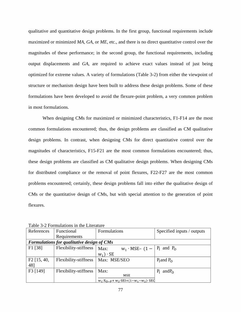
77
qualitative and quantitative design problems. In the first group, functional requirements include
maximized or minimized MA, GA, or ME, etc., and there is no direct quantitative control over the
magnitudes of these performance; in the second group, the functional requirements, including
output displacements and GA, are required to achieve exact values instead of just being
optimized for extreme values. A variety of formulations (Table 3-2) from either the viewpoint of
structure or mechanism design have been built to address these design problems. Some of these
formulations have been developed to avoid the flexure-point problem, a very common problem
in most formulations.
When designing CMs for maximized or minimized characteristics, F1-F14 are the most
common formulations encountered; thus, the design problems are classified as CM qualitative
design problems. In contrast, when designing CMs for direct quantitative control over the
magnitudes of characteristics, F15-F21 are the most common formulations encountered; thus,
these design problems are classified as CM qualitative design problems. When designing CMs
for distributed compliance or the removal of point flexures, F22-F27 are the most common
problems encountered; certainly, these design problems fall into either the qualitative design of
CMs or the quantitative design of CMs, but with special attention to the generation of point
flexures.
Table 3-2 Formulations in the Literature
References Functional
Requirements
Formulations Specified inputs / outputs
Formulations for qualitative design of CMs
F1 [38] Flexibility-stiffness Max: w1 ∙ MSE– (1 −w1) ∙ SE
PI and PO
F2 [15, 40,
48]
Flexibility-stiffness Max: MSE/SEO
PIand PO
F3 [149] Flexibility-stiffness Max: MSE
w1∙XO−P+ w2∙SEI+(1−w1−w2)∙ SEO
PI andPO

78
F4 [97] Flexibility-stiffness Max: MSE
w1∙SEI+(1−w1)∙ SEO XI andPO
F5 [77] Flexibility-stiffness Min: −ƞ(MSE)/μ(SEI),
where ∂ƞ(XO)
∂XO> 0;
∂g(SEI)
∂SEI> 0.
PI andPO = kO ∙ XO;
F6 [150] Flexibility-stiffness Max: output energy
SEI PI andPO = kO ∙ XO
F7 [14] Flexibility-stiffness Max: GA
SE
F8 [38] Flexibility-stiffness Min: SE PI andPO = kO ∙ XO
F9 [32] Output
displacement Max: XO PI , PI =g( XI ) and PO =
f(XO) F10 [44, 45,
48, 151]
MA Max: MA, s.t. XI≤ XI∗ PI and PO = f(XO)
F11 [45] GA Max: GA, s.t. XO≤ XO∗ PI and PO = ks ∙ XO
F12 [45] ME Max: ME, s.t. XO≤ XO∗ PI and PO = ks ∙ XO
F13 [48,
113]
ME Max: ME PI and PO
F14 [141] ME Max: ME PI and PO = ks ∙ XO
Formulations for quantitative design of CMs
F15 [152] GA* Min:
w1 ∙ (GA∗ −
XO
XI)2+(1-w1)(w2 ∙ SEI +
(1 − w2) ∙ SEO)
PI and PO
F16 [58] path generation Min: LSE1 XI and PO
F17 [47] path generation Min: LSE2 XI and PO = ks ∙ XO
F18 [89] path generation Min: LSE3 XI and PO
F19 [88] path generation Min: LSE4 PI and PO
F20 [63, 87] path generation Min: ∑wi ∙ erri PI and PO
Formulations for point flexure problem
F21 [153] Flexibility-stiffness Max: w1 ∙ MSE − (1 −w1) ∙ ∑ εi
2
PI and PO
F22 [49] Output
displacement Min: −
MSE
Φ PI and PO
F23 [48,
154]
Output
displacement Max:XO1,
subjecting toX∗ ≤ XI2
PI and PO = ks ∙ XO
F24 [52] Flexibility-stiffness Max: SE PI and PO = ks ∙ XO
F25 [48,
155]
GA* Max: e−(GA−GA∗)2K11K22 PI and PO
MSE: Mutual Strain Energy; SE: Strain Energy due to PI and PO.
SEO: Strain Energy due to the output force PO with the input port and the support region being
fixed.
SEI: Strain Energy due to input force PI with the output port and the support region being fixed.
w1, w2, … , wi: weighting factors.
XO−P: the displacement of the output port perpendicular to the desired direction.

79
erri: Fourier coefficients errors between the desired and actual paths.
εi: the strain due to input forces and output forces.
Φ: the sum of local relative rotations.
XO1: output displacement when two springs of high stiffness are connected both at the input and
at the output.
XI2: output displacement when only a spring of moderate stiffness is connected to the output.
K11, K22: the condensed stiffness matrices.
LSE1: min Φ = ∑ αj2j=0 ∑ [∆out,i,j − ∆out,i
∗ ]2Mi=1 ; LSE2: Φ = ∑ [(δxi − δxi
∗)2 + (δyi − δyi∗)2]M
i=1
LSE3: Φ = 1
M∑ [(δxi − δxi
∗)2 + (δyi − δyi∗)2]1/2M
i=1 .
LSE4: Φ = (Qi − Pi) ∙ (Qi − Pi) , where Qi denotes the actual deformation of the output port
for the actuation forces Fi while Pi is the desired deformation, i=1, 2, 3,…,n; n is number of
precision points (the un-deformed output position is not included).
Formulations for qualitative design of CMs: F1-F14. Within F1-F14, F1-F8 are for the
purpose of flexibility-stiffness, while F9-F14 are for mechanical functional requirements, e.g.,
MA, GA, etc. In F1-F8, the strain energy, a concept commonly used in the structural optimization,
is employed. Moreover, these formulations become a trend to design CMs for the so-called
flexibility-stiffness purpose: (1) flexibility to undergo desired deformations (kinematic
requirement); (2) Stiffness to bear external loads (structural requirement). Hence, multi-criteria
formulations are built to design CMs so that the CMs are flexible enough to deform and stiff
enough to resist loads. The flexibility is always formulated as Mutual Strain Energy (F1, F2, F3,
and F4) which numerically equals output deformation. Other formulations for flexibility include
a variant of MSE (F5), or mechanical properties, e.g., output energy (F6, F8), GA (F7). Since
stiffness, on the other hand, represents the compliance of a structure, so stiffness is formulated as
SE, which is essentially the compliance of a structure. The lower the strain energy, the stiffer the
structure. It is preferable to formulate these criteria in the form of a ratio (F2-F5) than to
formulate them in the form of a summation (F1). With the form of a ratio of these criteria, there
is no need to select weighting factors, and the multiple criteria have the same importance in the
objective function so that none of them will appear to dominate the combined objective function.

80
Regarding these multi-criteria formulations (F1-F7), researchers argued that if there was
no structural requirement, the optimal results tended to be infinitely flexible and connections
among points of interest could not be assured. However, this is not true for the following reasons:
First, from the viewpoint of the design problems of CMs, stiffness is not even a primary
requirement for a mechanism; therefore, it is not reasonable to consider it as the primary
requirement in formulations, e.g., output forces, output displacement. Second, the reason why
connections are not ensured is that the employed optimization algorithms cannot avoid
topologically disconnected topologies. However, connected topologies can actually be guaranteed
by improving the ability of algorithms instead of considering stiffness in formulations. Lu and
Kota [59] developed a representation of load path scheme to avoid topological disconnected
structures. The scheme excludes topological disconnected structures at the beginning of
optimization. Zhou and Ting [156] introduced spanning tree theory to weed out invalid
disconnected topologies. Third, maximizing stiffness, either explicitly or implicitly, leads to
lumped CMs, where point flexures appear, so that these CMs cannot be manufactured and
function well in practical use. The point flexure problem is discussed further in the next section.
Fourth, infinitely flexible topologies can be avoided by considering constraints on input or output
displacements, stress, etc. To sum up, stiffness should not be as important as functional
requirements as a criterion of mechanisms, e.g., output forces and output displacements, in the
design of CMs.
Ananthasuresh [38] designed CMs by minimizing SE (F8) under the case of spring model,
where SE equals the difference of input energy and energy stored in the spring. The spring model
captures the feature of the work-piece the mechanism works with. The stiffness of the spring is
chosen depending on the stiffness of the work-piece, a hard work-piece can be modeled as a

81
spring with high stiffness and vice versa. Minimizing SE is actually to find a balance of input
energy (minimizing input energy) and energy stored in the spring (maximizing energy stored in
the spring). The input energy is determined by the input force and input displacement while the
energy stored in the spring is determined by deformation of the spring (or the output
displacement) and the stiffness of the spring. Comparing with F1-F7, F8 is compact and it gives
more reasonable results. However, in F8, a very careful choice of input force and stiffness of the
spring is required to get reasonable optimal topology. Both of the input force and the stiffness of
the spring need to match each other so that neither of them dominates the value of SE.
Nevertheless, in the practical use of CMs, there is no much space for designers to pick input
forces and work-pieces. Further, the output displacement is only implicitly included in the
objective function while mechanisms are always designed for explicit displacement
requirements.
In F9-F14, instead of being designed for structural properties, i.e., maximized strain
energy, CMs are designed purely for mechanical functional requirements, e.g., output
displacement (F9), MA (F10), GA (F11) ME (F12-F14). Sigmund [147] designed displacement
amplifiers by maximizing the output displacement (F9). Both the actuator and work-piece were
modeled as springs. Sigmund [44] formulated MA (F10) as objective function to design CMs and
two loading conditions were considered, i.e., with gap or without gap between the CM and the
work-piece. Lau et al. [45] considered MA (F10), GA (F11) and ME (F12) as objective functions
respectively. Resistance force due to work-piece was considered using the spring model. The
properties of obtained topologies were consistent with the employed objective functions from the
viewpoint of mechanical performances. By considering formulations for mechanical functional
requirements in the design of CMs, instead of getting the same results with those for

82
flexibility-stiffness purpose, optimal topologies, whose performances are consistent with the
mechanical functional requirements, can be obtained. However, there are nonlinear constraints in
all the formulations for MA and GA, which brings difficulty in algorithm convergence [48] and
the results suffer from point flexure problem [48, 148].
Canfield and Frecker [141] designed compliant displacement amplifier for stack
actuators by maximizing ME (F14), which was the product of GA and MA. GA is measured
under the free displacement condition and the MA is measured under the blocked force condition,
and these conditions cannot be simultaneously obtained, the defined ME does not exactly capture
the real mechanical efficiency of the system and it only represents a theoretical maximum [17].
Moreover, even though the spring model is considered for the work-piece, the resistance force
from the work-piece is not included into the kinematic analysis and it is only for the calculation
of output energy which is stored in the spring.
For formulations regarding ME, it is not necessary to add any kinematic constraints, since
ME is naturally constrained to be less than one. From this point of view, it is more convenient to
implement the optimization problem of the ME formulations (F13 and F14). However, it is
mainly dependent on the design problems regarding which formulation to select.
Besides the above discussion regarding these formulations, several problems need to be
pointed out:
First, the results are all sensitive to the output loads, i.e., the magnitude of output forces,
the stiffness of springs at the output port. Second, the results suffer from point flexure problem
and it is essentially common in all formulations. Third, CMs are designed in a qualitative sense
instead of a quantitative sense. However, according to the discussions on DPA to DPN, CMs are
always required to generate exact magnitude of displacements or forces. Fourth, most
83
formulations specify input forces rather than input displacements. However, according to the
previously defined design problems (DPA-DPN), not only forces, but also motions could be
specified as inputs of a mechanism. In addition, specifying displacements as inputs have several
benefits, i.e., the solutions are less sensitive to the lower bounds of design variables. Last but not
the least, inputs could also be set design variables instead of being specified since in the case of
large deformation, specifying inputs may result in the missing of possible optimal topologies of
CMs which can generate the motion required under the actuation of other inputs. This point also
fits to the mechanism kinematic design problem, i.e., path generation without prescribed timing
and motion generation without prescribed timing design problem, only the output motions are
concerned. Fifth, only translational inputs are considered in these formulations, however,
rotational motions or forces are not considered (Equations (3.1) and (3.2)) while rotational inputs
or outputs are essential and common in applications, i.e., optical modulating component
modulator (driven by a comb actuator) which needs a planar angular rotator to control different
angles and to modulate the dissimilar light [142].
Formulations for quantitative design of CMs: F15-F21. Min and Kim [152] designed
CMs for specified magnitude of GA (F15) so that GA could be controlled directly and
quantitatively. F16-F20 are formulations to design CMs for path generation based on the
previously defined DPB or DPF. Pedersen et al. [58] designed path-following CMs (F16) so that
the output port passes the precision points due to corresponding input displacements, and it also
passes the same precision points when two separate counter loads (output forces) are applied at
each precision points. One is against the output direction and one is perpendicular to the output
direction (Figure 3-4).The input forces are constrained to upper limits. A weighted sum of Least

84
Square Errors (LSE), which is the difference between the desired output displacements and the
obtained output displacement, is formulated for the synthesis of CMs for path generation.
Figure 3-4 Path with counter loads [58]
Including the counter loads in this model makes the optimal mechanism stiff enough to
resist the counter loads. However the counter load in this model is selected based on the
input/output displacement and the actuator, which is not true. In reality, the counter load is
dependent on the work-piece the mechanism works with, instead of actuators. In addition, this
model only guarantees the deformation in the desired direction, the deformation in its
perpendicular direction is not concerned so that the output port may not pass through the
precision points even though the error function is very close to zero.
Saxena and Ananthasuresh [47] designed CMs for path generation (F17) with a sum of
least square errors (LSE2) in a x-y coordinate system while the work-piece the CM works with
are modeled as linear springs. Precision points in the design domain are described with an x-y
coordinates so that the output port needs to traverse through points P𝑖 of coordinates (𝛿xi∗, 𝛿yi
∗)
with respect to its undeformed position due to input forces. The work piece at the output port is
modeled as two linear springs. Here, two linear springs are added along the x and y displacement
directions at the output port to simulate the resistance along the linear path. However, like all
other models based on the spring model, the optimal results highly depend on the stiffness of the
Precision points
Counter loads
Path

85
two springs. Moreover, the spring model cannot precisely capture the complicated interaction
between the CM and the work-piece in the case of path generation.
Tai et al. [89] designed path following CMs (F18) so that the output port passed a
sequence of precision points on a path with specified input displacements and specified output
forces (output forces are specified as zero). The magnitudes of the input displacements were
given, and the forces that needed to generate the input displacements were constrained to an
upper limit. However, the output loads were specified as zero so that the connections cannot be
guaranteed if no other filter were employed.
Saxena [88] designed path following CMs (F19) so that the output port passed a sequence
of precision points on a path with specified input forces and specified stiffness of spring at the
output port. There were n objectives functions for n precision points. The multiple objectives
were minimized simultaneously, and a set of Pareto optimal solutions among were obtained. In
these solutions, a solution that corresponds to the minimum of each objective existed, and the
solution of the combined summation of all the individual objective functions also existed. This
idea may provide designers more choices for desired solution from these Pareto optimal ones.
But results showed that all the optimal results could only capture the trend of the specified path,
but could not be desirably close to the specified path.
The optimal synthesis of mechanisms for path generation commonly minimizes the sum
of error functions, taking the mean squared distance between the obtained curve and the desired
curve over a number of precision points as the structural error. The error function attempts to
compare the shape, size, orientation, and location of a desired curve with an actually obtained
curve all at once thereby simultaneously limiting the search space and making the search
intractable.

86
Besides the LSE functions, Fourier Descriptors method [157] was employed to formulate
the objective function (F20) for the path following CMs optimal synthesis by Rai et al. [63]. The
Fourier Descriptors objective function compares purely the shape of two plane curves without
being affected by the location, size, or orientation differences between curves. If the shape of the
actual obtained curve is the same as the desired one, by translating, rotating and scaling the
solution mechanism appropriately, without changing topology of the mechanism, the solution
curve can be made to coincide with the desired curve in shape, position, orientation and size.
Apparently this may make the design non-systematic since human interruptions are required to
change the design to meet the function requirements.
We conclude that there are mainly two types of formulations for the design of
path-following CMs. One is the formulations based on the LSE and the other is based on the
Fourier Descriptors. Although there are different forms of LSE functions, the essence in these
forms is the same, i.e., the coordinate differences of precision points on the path. With the LSE
formulation, one can design CMs for any kinds of output displacement requirements or any kinds
of input-output relationships. For example, one can design CMs for linear or nonlinear
input-output relationship [47, 58]; one can also design CMs to follow linear or nonlinear paths
[58, 88]. This is very essential since designers can directly, precisely and quantitatively control
the inputs and outputs; while F1-F14 are only for the qualitative design CMs. In contrast, with
the formulations based on Fourier Descriptors, one can only design a CM to follow the shape of
a path; thus, this approach is only useful when the shape of a path is the concern.
In addition, formulations for the design of path-following CMs also have the same
problems as stated as the first, second and fifth points in previous part of this section.

87
3.3.3 Formulations for Point Flexure Problem
A common problem in the above mentioned formulations is the presence of point
flexures, i.e., two solid elements connect to each other diagonally by one node, as shown in the
circled regions in Figure 3-5 and Figure 3-6. Point flexures undesirable in CMs since it is
impossible to manufacture them, and replacements have to be employed [49]. Moreover, even
replacements are used, they still suffer high stress, which leads to yield failure, or fatigue failure.
The presence of point flexures leads to a lumped compliant system whose compliance is
concentrated on several local regions as opposed to the desired one called distributed CM whose
compliance is distributed evenly to the whole body of the CM. There are methods taking efforts
to design CMs without point flexures by considering alternative parameterization methods or
filters; however, only methods on alternative formulations are discussed in the paper.
Figure 3-5 An optimal topology for a compliant gripper from F13 [48]
Figure 3-6 An optimal topology for a path-following CM from F16 [58]
Yin and Ananthasuresh [49] proposed a method to restrain local, relative rotation with a
novel that hopes to make the local deformation uniform throughout the structure. It is explained
that the optimization algorithm tends to generate point flexures since they undergo for large
Point flexure
Point flexure
88
displacements without the cost of high strain energy, both of which are just what are desired in
the formulations. For example, in F2, the ratio of output displacement to the strain energy is
maximized, point flexures is just the ideal component that can maximize the ratio. With the
relative rotation being restrained, the formulation (F22) is able to remove point flexures and give
distributed compliant designs. However, this approach only restrains the relative rotations, which
actually limits the degree of lumped compliance but it does not touch the essence of the problem,
i.e., it is the formulation that prefers to topologies with minimum strain energy in a CM and
maximum displacement at the output port, which leads to the tendency of lumped compliance,
even point flexures. Restricting the relative rotation can only prevent the relative rotation but it
cannot change the tendency of lumped compliance.
With the similar explanation for the point flexure problem, Cardoso and Fonseca [52]
stated that strain energy should not be minimized since a distributed CM must spend a part of the
input energy in the form of strain energy to deform. Therefore, Cardoso and Fonseca [52]
maximized the strain energy (F25), imposing kinematic functional requirements as constraints.
However, enough strain energy in the elastic body is only a necessary condition to be a
distributed CM but not a sufficient condition; therefore, the formulation cannot ensure the
removal of point flexures in optimal topologies. In addition, the specifications of the design
should be very carefully selected, e.g., kinematic constraints, input force and output forces need
to be selected carefully to guarantee distributed CMs without point flexures. Lastly, a CM
designed from this formulation has low ME since the stored strain energy is large inside the
elastic body.
Wang [140] developed F26 to eliminate point flexures, arguing that the true optimum of
the optimization problem as posed was a rigid-body linkage with revolute joints. More

89
specifically, a kinematically permissible solution can generate large output displacement and has
minimum strain energy; therefore, the optimization algorithm tends to generate solutions that
closely imitate a rigid-body linkage by means of point flexures. Wang [140] also found three
necessary conditions on the derived input stiffness matrix KI, output stiffness matrix KO and
strucrue stiffness matrix KS from the mechanism stiffness matrix Km which was ultimately
from the global stiffness matrix. Both KI and KO have to be non-singular to ensure point
flexure-free. For example, if any of KI and KO is singular, the Km is semi-definite so that the
mechanism’s structure permits an internal rigid-body displacement mode which results in point
flexures in the optimal design. Thus, it is necessary to eliminate any rigid-body displacement
mode in the CM to avoid any point flexures by maintaining KI and KO non-singular. These
necessary conditions are formulated into F26. However, the presence of lumped compliance or
point flexures cannot be completely prevented, since it similarly restrains the rigid-body motion.
Wang [64] and Yin and Ananthasuresh [49] shared the same idea, i.e., to restrain the motion;
however, they did not change the tendency of lumped compliance. In addition, Deepak et al. [48]
also found that when the mechanical specification was not set properly, e.g., the desired GA was
too large, point flexures still appeared in the optimum.
Lee [153] designed CMs with a strain based formulation. He argued that in the
conventional strain energy based formulation, an element with large strain but low material
density had no priority to get more material distribution even though it was supposed to get more,
which leaded to localized deformation or even point flexures. Thus, a strain based formulation
(F21) was developed to eliminate this distortion by formulating the strain rather than strain
energy of each element in the objective function. The new formulation reduced localized high

90
deformation in CMs in some degree but the presence of point flexures was still hard to be
avoided in the demonstrated examples.
The underlying reasons for the presence of point flexures in the topological design of
CMs are still in debate in the literature, and a variety of formulations have been taken to deal
with this problem. However, most of the formulations, though with more criteria, are still based
on the conventional formulations, which tend to generate point flexures. Thus, no universal
formulation in the literature completely avoids this problem. Efforts must be taken to find out
new formulations which are not limited by the ideas behind conventional formulations.
3.4 Conclusions and Future Work
In the literature, CMs have been mostly designed for the balance of flexibility and
stiffness, and maximized MA, GA or ME. However, design problems and formulations as
defined with these attributes are not the main streams of design problems of mechanisms, i.e.,
function generation, path generation and motion generation. Thus, general Design Problems
(DPA~DPL) of CMs through the TO are defined in this paper due to the lack of comprehensive
definitions for design problems of CMs in the literature. Typical design problems of rigid body
mechanisms, i.e. function generation, path generation and motion generation, are extended to the
design problems of CMs based on DPA~DPL.
Boundary conditions or working conditions that have been considered in the literature are
also reviewed. The spring model captures the behavior of actuators or work-piece and it has been
widely accepted in the literature. However, the optimal results are highly dependent on the
stiffness of springs [145, 148] so that the optimal CMs can only work properly with work-pieces
which have the same stiffness as the one in the design specification, while in practice a CM may
interact with different work-pieces. In addition, the modeling of work-pieces or actuators needs

91
to be improved and rotational motions or forces need to be considered since only translational
motions or forces have been considered in the literature.
Future work regarding boundary conditions lies in (1) the accurate modeling of
work-pieces in the case of path generation and motion generation CMs; (2) the design of CMs
which are not sensitive to the stiffness of work-piece or actuators; (3) the design of CMs with
variable boundaries conditions, e.g., consider input force as an design variable or support regions
as an design variable; (4) consider rotational inputs and outputs; (5) the design of CMs with
specified actuators and output forces, i.e., the design specification ③.
Functional requirements and the associated formulations (F1-F25) in the literature are
comprehensively reviewed along with their limitations. Based on whether the output is
controlled quantitatively or not, the formulations can be categorized into two types: (1)
formulations for quantitative design of CMs; (2) formulations for qualitative design of CMs. In
addition, formulations that aim to solve the point flexure problem are also discussed.
Formulations for the qualitative design of CMs cannot satisfy the defined design problems while
formulations for the design of path following CMs partly satisfy the defined design problem in
some degree although it is incomplete, and the improvement of the modeling of actuators and
work-pieces is still in demand.
Lastly, an overview of the formulations for the point flexure problem is presented. Most
of these formulations, although with more criteria, are still based on the conventional
formulations, generating point flexures in results. Thus, no universal formulation yet in the
literature ensures point flexure-free results. New formulations, point flexure-free by their nature,
need to be developed in the future.

92
Acknowledgements
The first author wants to acknowledge the financial supports from the China Scholarship
Council and the East China University of Science and Technology. The corresponding author
wants to acknowledge the financial support received from the NSERC through a discovery grant.
The first author also thanks Heather Mcwhinney for assisting in proof-reading this paper.

93
CHAPTER 4
HYBRID COMPLIANT MECHANISM DESIGN BY A MIXED MESH OF BEAM
ELEMENTS AND A NEW SUPER FLEXURE HINGE ELEMENT THROUGH A
TOPOLOGY OPTIMIZATION TECHNIQUE
Chapter 4 presents the first study for Objective 2. Specifically, the concept of hybrid
CMs is highlighted, and a framework for the systematic analysis and synthesis of hybrid CMs is
presented. This study integrates flexure hinges and beams for hybrid CM design by taking
advantage of their complementary inherent properties in stress distribution and energy efficiency.
Hybrid CMs provide a way to physically integrate lumped compliance of flexure hinges and
distributed compliance of beams together for better performance. Note that the focus of this
chapter is on integrating flexure hinges and beams for hybrid CM design, without the
consideration of stress issues. The design results are only efficient and may not be strong. Stress
issues are considered in Chapter 5.
The work presented in this chapter is included in the following manuscript:
Cao, L., Dolovich, A., and Zhang, W. J., 2014, “Hybrid Compliant Mechanism Design
using a Super Flexure Hinge Element through a Topology Optimization Technique”, ASME
Journal of Mechanical Design, Research Paper, Accepted with minor revision pending,
manuscript ID: MD-14-1780.
Abstract
This paper proposes a topology optimization framework to design compliant mechanisms
by meshing the design domain with both beams and flexure hinges. Both the presence or absence
of beams and flexure hinges and the locations and sizes of flexure hinges were defined as design
variables to be determined by the optimization process. Further, a new type of finite element, i.e.,

94
super flexure hinge element, was developed to model flexure hinges. The proposed meshing
scheme and topology optimization technique allow designers to utilize flexure hinges in
compliant mechanisms and facilitate the rational decision on the locations and sizes of flexure
hinges in lumped compliant mechanisms with flexure hinges and hybrid compliant mechanisms
with both flexible beams and flexure hinges. Furthermore, an investigation into the effects of the
location and size of a flexure hinge in a simple compliant mechanism explains why the problem
of point flexures often occurs when the conventional stiffness-flexibility criteria are used in
topology optimization. Two design examples were presented to verify the proposed technique.
The effects of link widths and hinge radii were also investigated. The results indicate that the
proposed super flexure hinge element makes the analysis and synthesis of hybrid compliant
mechanisms more efficient and accurate.
Keywords: compliant mechanism, flexure hinge, topology optimization.
4.1 Introduction
A CM is a mechanism that generates at least parts of its motion through the deformation
of its flexible components [2]. A main type of flexible component in CMs is the flexure hinge
[158-162], as shown in Figure 4-1a. Flexure hinges mimic the pin joints in rigid-body
mechanisms; therefore, a typical way to design CMs is to directly replace the pin joints in a
selected rigid-body mechanism with flexure hinges, namely the rigid-body replacement method
[2, 163]. However, this replacement method needs to start from an initially selected rigid-body
mechanism. This selection, a very traditional thinking in rigid-body mechanism design, is a
difficult task and called type synthesis [55]. This paper aims to develop a TO framework which
designs CMs with flexure hinges being explicitly considered in the design process and does not
rely on an initially selected mechanism.

95
Many research efforts have been devoted in developing TO techniques [32] for CM
design [38, 48, 164-166]. The significance of TO lies in the fact that the initial selection of a
proper mechanism topology is not required. One of the most widely used approaches among
these techniques is the ground structure approach [61, 97] which discretize a design domain with
beam elements; the design results using this approach consists of only beams, as shown in Figure
4-1b. This study further developed the ground structure approach by meshing the design domain
with both beams and flexure hinges. Both the presence or absence of beams and flexure hinges
and the locations and sizes of flexure hinges were considered as design variables. Further, a new
type of finite element—super flexure hinge element—was developed to model flexure hinges.
The proposed technique facilitates the design of lumped CMs with flexure hinges (Figure 4-1a)
and hybrid CMs [101, 103] with both flexible beams and flexure hinges (Figure 4-1c). Hybrid
CMs take advantages of the complementary mechanical properties of beams and flexure hinges
in stress distribution, ability to generate pure rotation, or natural frequency [101-103] to achieve
good or balanced performance in these properties. The focus of this study was to incorporate
both flexure hinges and beams in the TO technique, leaving the question of how to balance their
complementary properties as a future work. Thus, CMs in this study were designed to fulfill the
stiffness-flexibility criterion [48, 76] only, and a rational decision on the locations and sizes of
flexure hinges in the design domain was the target.
The remainder of this paper is organized as follows. In Section 4.2, the super flexure
hinge element is developed. Using this element, Section 4.3 investigates the effects of the
location and size of a flexure hinge in a simple CM. In Section 4.4, the proposed TO technique
using both super flexure hinge elements and beam elements is described. Two design examples
are presented in Section 4.5. Section 4.6 concludes the paper.

96
Figure 4-1 Three types of CMs: (a) a lumped CM with flexure hinges [162], (b) a distributed CM
with beams [167], and (c) a hybrid CM with both flexure hinges and beams [102]
4.2 Super Flexure Hinge Element
In this section, we introduce the super flexure hinge element to model one type of the
most commonly used flexure hinges—circular flexure hinges (Figure 4-2a). The stiffness matrix
of the element was derived from the stiffness equations in [168, 169] and was then verified
using ANSYS.
4.2.1 Stiffness Matrix
Figure 4-2a shows a two-dimensional circular flexure hinge whose stiffness properties in
three directions are essential: the rotational stiffness 𝑘𝛼 (𝑀𝛼 𝛼)⁄ and the translational stiffness
components 𝑘𝑥 (𝐹𝑥 ∆𝑥⁄ ) and 𝑘𝑦 (𝐹𝑦 ∆𝑦⁄ ). The equations for these stiffness properties can be
found in [169-172]. The accuracy of these equations highly depends on the t/R ratio (t is the
in-plane thickness of the thinnest section of a flexure hinge, and R is the radius of the circular
shape of the flexure hinge) [168]. In our case, the equations are desired to be accurate over a
wide range of the t/R ratio. The rotational stiffness equation 𝑘𝛼 in [169] was used because it is
the most accurate one (average error is 1.2% compared to the results from ANSYS) with the
widest range of the t/R ratio (0.05 ≤t/R≤ 0.65) compared to other equations. The empirical
(a) (b) (c)
Flexure hinge

97
equations in [168] (based on ANSYS results) were used for the translational stiffness equations
of 𝑘𝑥 and 𝑘𝑦. The average errors of the equations of 𝑘𝑥 and 𝑘𝑦, with the t/R ratio in the range
of 0.5 to 0.8, are 0.07% and 0.08%, respectively. The three stiffness equations were further used
to derive the stiffness matrix of the super flexure hinge element. The three equations are included
in the Appendix of this paper.
The super flexure hinge element has two nodes, and each node has three degrees of
freedom, as shown in Figure 4-2b. The equilibrium equation (in the local coordinate system) for
the element is:
𝐹6×1 = 𝐾6×6 ∙ 𝑈6×1, (4.1)
where 𝐹6×1 is the external force vector, i.e., [𝐹𝑖𝑥 𝐹𝑖𝑦 𝑀𝑖𝛼 𝐹𝑗𝑥 𝐹𝑗𝑦 𝑀𝑗𝛼]𝑇
, 𝐾6×6 is the
stiffness matrix, and 𝑈6×1 is the displacement vector.
𝑀𝑗𝛼
𝐹𝑖𝑥
𝐹𝑖𝑦
𝑀𝑖𝛼
i
𝐹𝑗𝑦
𝐹𝑗𝑥 j
𝐹𝑗𝑦
𝐹𝑗𝑥 j
𝑀𝑗𝛼
𝐹𝑖𝑦
𝑀𝑖𝛼
i
(b)
𝑀𝑗𝛼
𝐹𝑖𝑥
𝐹𝑗𝑦
𝑀𝑖𝛼
i
j 𝐹𝑗𝑥 𝐹𝑖𝑦
(a)
Figure 4-2 (a) a circular flexure hinge, (b) the super flexure hinge element, and (c) one
deformed configuration of the element under a specified loading case
(c)
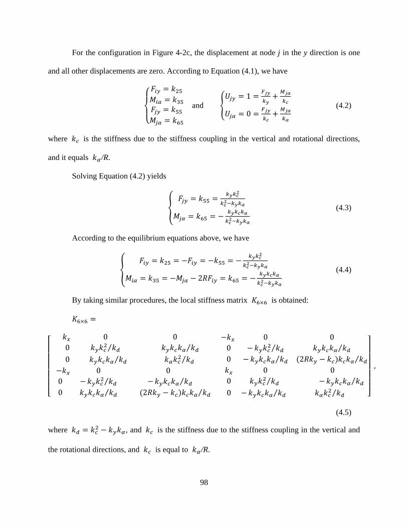
98
For the configuration in Figure 4-2c, the displacement at node j in the y direction is one
and all other displacements are zero. According to Equation (4.1), we have
{
𝐹𝑖𝑦 = 𝑘25𝑀𝑖𝛼 = 𝑘35𝐹𝑗𝑦 = 𝑘55𝑀𝑗𝛼 = 𝑘65
and {𝑈𝑗𝑦 = 1 =
𝐹𝑗𝑦
𝑘𝑦+𝑀𝑗𝛼
𝑘𝑐
𝑈𝑗𝛼 = 0 =𝐹𝑗𝑦
𝑘𝑐+𝑀𝑗𝛼
𝑘𝛼
(4.2)
where 𝑘𝑐 is the stiffness due to the stiffness coupling in the vertical and rotational directions,
and it equals 𝑘𝛼/R.
Solving Equation (4.2) yields
{𝐹𝑗𝑦 = 𝑘55 =
𝑘𝑦𝑘𝑐2
𝑘𝑐2−𝑘𝑦𝑘𝛼
𝑀𝑗𝛼 = 𝑘65 = −𝑘𝑦𝑘𝑐𝑘𝛼
𝑘𝑐2−𝑘𝑦𝑘𝛼
(4.3)
According to the equilibrium equations above, we have
{𝐹𝑖𝑦 = 𝑘25 = −𝐹𝑖𝑦 = −𝑘55 = −
𝑘𝑦𝑘𝑐2
𝑘𝑐2−𝑘𝑦𝑘𝛼
𝑀𝑖𝛼 = 𝑘35 = −𝑀𝑗𝛼 − 2𝑅𝐹𝑖𝑦 = 𝑘65 = −𝑘𝑦𝑘𝑐𝑘𝛼
𝑘𝑐2−𝑘𝑦𝑘𝛼
(4.4)
By taking similar procedures, the local stiffness matrix 𝐾6×6 is obtained:
𝐾6×6 =
[
𝑘𝑥 0 0
0 𝑘𝑦𝑘𝑐2 𝑘𝑑⁄ 𝑘𝑦𝑘𝑐𝑘𝛼 𝑘𝑑⁄
0 𝑘𝑦𝑘𝑐𝑘𝛼 𝑘𝑑 ⁄ 𝑘𝛼𝑘𝑐2 𝑘𝑑⁄
−𝑘𝑥 0 0
0 −𝑘𝑦𝑘𝑐2 𝑘𝑑⁄ 𝑘𝑦𝑘𝑐𝑘𝛼 𝑘𝑑⁄
0 −𝑘𝑦𝑘𝑐𝑘𝛼 𝑘𝑑⁄ (2𝑅𝑘𝑦 − 𝑘𝑐)𝑘𝑐𝑘𝛼 𝑘𝑑⁄
−𝑘𝑥 0 0
0 − 𝑘𝑦𝑘𝑐2 𝑘𝑑⁄ − 𝑘𝑦𝑘𝑐𝑘𝛼 𝑘𝑑⁄
0 𝑘𝑦𝑘𝑐𝑘𝛼 𝑘𝑑⁄ (2𝑅𝑘𝑦 − 𝑘𝑐)𝑘𝑐𝑘𝛼 𝑘𝑑⁄
𝑘𝑥 0 0
0 𝑘𝑦𝑘𝑐2 𝑘𝑑⁄ − 𝑘𝑦𝑘𝑐𝑘𝛼 𝑘𝑑 ⁄
0 −𝑘𝑦𝑘𝑐𝑘𝛼 𝑘𝑑⁄ 𝑘𝛼𝑘𝑐2 𝑘𝑑⁄ ]
,
(4.5)
where 𝑘𝑑 = 𝑘𝑐2 − 𝑘𝑦𝑘𝛼, and 𝑘𝑐 is the stiffness due to the stiffness coupling in the vertical and
the rotational directions, and 𝑘𝑐 is equal to 𝑘𝛼/R.

99
Note that Equation (4.5) is accurate in the range of 0.05 ≤t/R≤ 0.65 due to the
limitation of the employed rotational stiffness equation [169].
4.2.2 Model Verification
An example was taken to verify the stiffness matrix of the super flexure hinge element.
Figure 4-3a shows two beams connected through a flexure hinge. The left end of the structure is
clamped, while the right end is loaded with an axial force 𝐹𝑥 and a transverse force 𝐹𝑦. The t/R
ratio of the flexure hinge varies from 0.05 to 0.65 with an increment of 0.01. The specifications
of the structure are listed in Table 4-1.
The structure was first analyzed using the new model, i.e., two beam elements (𝑒1 and 𝑒3)
and one super flexure hinge element (𝑒2), as shown in Figure 4-3b; then, the structure was also
analyzed using PLANE82 elements in ANSYS, as shown in Figure 4-3c. Mapped mesh was used
to mesh the structure for better control of elements and nodes. Sensitivity analysis (refining the
mesh and changing material properties and input forces) was also performed to ensure that the
analysis results were not mesh-dependent. Analysis and comparisons between the two above
approaches were conducted by varying the t/R ratio from 0.05 to 0.65, with an increment of 0.01.
Three terms are considered: the horizontal and vertical displacements (𝑈3,𝑥 and 𝑈3,𝑦) of the
point at the location of node 3. Node 3 was chosen because the cross section at node 3 bears
moments, vertical forces, and horizontal forces, so that the stiffness matrix of the flexure hinge
element could be verified in all types of loadings.
Figure 4-4 shows the results from the new model (using the super flexure hinge element)
and ANSYS. The displacements calculated through the new model and ANSYS were fairly close:
the relative errors for 𝑈3,𝑥 vary from 4% to -4.2%, and those for 𝑈3,𝑦 vary from -2.5% to -6.3%
when the t/R ratio increases from 0.05 to 0.65. These errors are acceptable and suggest that the

100
stiffness matrix for the flexure hinge element is accurate enough for the analysis of CMs which
have flexure hinges. Moreover, the super flexure hinge element is fairly efficient in terms of
computational cost and thus it is incorporated into the TO technique for CM design in this study.
Figure 4-3 Verification for the super flexure hinge element
(a)
(b)
R
L L
W 𝐹𝑥
𝐹𝑦
𝑒1 𝑒2 𝑒3
1 2
3 4
(c)

101
Table 4-1 Specifications for verification
Young’s
Modulus
Poisson
ratio
Horizontal
force 𝐹𝑥
Vertical
force 𝐹𝑦
In-plane
width W
Out-of-plane
depth
Length L of
each link
105 GPa 0.33 100 N 100 N 10 mm 10 mm 40 mm
Figure 4-4 (a) 𝑈3,𝑥 calculated from the new model and ANSYS, (b) 𝑈3,𝑦 calculated from the new
model and ANSYS, and (c) relative errors between results from the new model and those from
ANSYS.
4.3 A Simple Compliant Mechanism
The existing TO techniques based on quadrilateral finite elements often get lumped CMs
and even CMs with point-hinges [49, 52, 53, 153]. Studies [48, 49, 64] have shown that the
(b)
(c)
(a)

102
fundamental optimization formulations is mainly responsible for the problem. The existing
formulations such as the ratio of strain energy and mutual strain energy, mechanical advantage
(MA), geometric advantage (GA), and mechanical efficiency (ME) all tend to transfer as much
energy, motion, or force as possible from the input port to the output port of the mechanism.
Thus, TO algorithms with those formulations often result in CMs with point hinges or highly
lumped CMs. Few studies have studied the effects of the size and location of a flexure hinge on a
CM. In this study, we investigated how the performance of a simple compliant lever changes by
changing the size and location of a flexure hinge in it. The super flexure hinge element was used.
Figure 4-5 (a) a compliant lever and (b) its rigid counterpart
Figure 4-5a shows a compliant lever which amplifies the input motion at the output port.
The output port is attached with a spring which would apply a resistance force to the lever if
deformed. A flexure hinge locates between the input port and the left end of the lever. In essence,
the compliant leverage mimics the function of a rigid lever in Figure 4-5b: the flexure hinge in
Figure 4-5a mimics the pin joint in Figure 4-5b. The relevant parameters are listed in Table 4-2.
The location of the flexure hinge on a link is determined by the generalized coordinate χ
(non-dimensional) of the hinge, which is the ratio of the distance from the first end point of the
link to the center of the flexure hinge and the total length of the link. For instance, if the length of
the link is L (from the first end to the other end of the link), the hinge locates on the link and the
Input Input
𝜒 × 𝐿
𝐿 𝐿
(a) (b)
Output spring 𝐾𝑠
Output spring 𝐾𝑠

103
distance from first end to the center of the hinge is χ × 𝐿. In the study, five different hinge
locations were considered, i.e., χ = 0.25, 0.40, 0.55, 0.70, and 0.85, respectively. For each hinge
location, the t/R ratio of the hinge is varied from 0.05 to 0.65 with an increment of 0.01. Every
set of hinge location and t/R ratio represents a different leverage design. Note that, with specified
in-plane width of a link, increasing t/R ratio of a flexure hinge on the link actually increases the
in-plane thickness t of the thinnest section of the flexure hinge and decreases the radius R of the
flexure hinge. The input displacement 𝑢𝑖𝑛, mechanical efficiency ME, geometrical advantage GA,
and mechanical advantage MA of these designs were investigated.
Table 4-2 Parameters of the compliant lever
Young’s
modulus
Input force
𝐹𝑖𝑛
Spring
stiffness 𝐾𝑠 In-plane
width W
Out-of-plane
depth
Length L
1.4 GPa 1 N 300 N/m 6 mm 5 mm 40 mm
Figure 4-6 shows the performance of the compliant lever with different sizes and
locations of hinges. It is seen that, when the hinge is at the thinnest size (t/R = 0.05) and at the
left end (χ = 0.25) of the link, the lever has maximum 𝑢𝑖𝑛, 𝑢𝑜𝑢𝑡 and MA, and ME in this case is
also at relatively large (83%). This means that the lever is very flexible and meanwhile has good
force and energy transfer capability, which satisfies the criteria of stiffness and flexibility [48,
76]. It is also seen that GA increases rapidly but then drops slowly or does not change when the
hinge becomes thicker (t/R increases). GA reaches the maximum when t/R is around 0.2 and χ is
0.7. These results suggest that the location of the hinge on the link makes a big difference on the
performance of the CM. In addition, these results explain why point flexures often occur in TO
results when the stiffness-flexibility multi-criterion is formulated as objective functions—a point
flexure, similar as a flexure hinge, improves the flexibility and stiffness of a design.

104
Figure 4-6. Performance of the compliant lever with different hinge locations and t/R ratios: (a)
input displacement 𝑢𝑖𝑛 , (b) Output displacement 𝑢𝑜𝑢𝑡 , (c) geometrical advantage GA, (d)
mechanical advantage MA, and (e) mechanical efficiency ME.
(a) (b)
(c) (d)
(e)
χ = 0.25
χ = 0.40
χ = 0.55
χ = 0.70
χ = 0.85

105
4.4 Topology Optimization
TO is a highly integrated systematic approach for structural synthesis, and it involves
four aspects: parameterization of design domain, optimization formulation, optimization
algorithm, and finite element analysis. The parameterization of a design domain consists of the
discretization of the domain and the definitions of design variables. A design domain is first
discretized into discrete units. Then, design variables which are related to the physical
parameters of those units such as material density [39] or cross-sectional area [40] are assigned
to these units. By determining the values of the design variables and thus the states of those units:
removed or kept and even the sizes, the topology and geometry of a CM can be determined.
Optimization formulations, including objective functions and constraints, are formulated to
represent design criteria (function requirements and constraints). Together with mechanism
evaluations based on finite element analysis, an optimization algorithm is used to find the
optimal values of the design variables and hence gives optimized topologies.
This section introduces the parameterization scheme, finite element analysis, and the
optimization algorithm that were employed in this study. The objective functions for
optimization problems are application-specific and thus are introduced in Section 4.5 where
examples are discussed.
Parameterization. In this TO approach, a design domain is discretized into a network of
straight links, as shown in Figure 4-7. Each link has three possible states during the design
process: being removed from the domain, stays in the domain and without a flexure hinge on it,
or stays in the domain but with a flexure hinge on it. The design task is to determine (1) which
links to keep in the domain and their in-plane widths 𝑊; (2) whether a flexure hinge exists on a
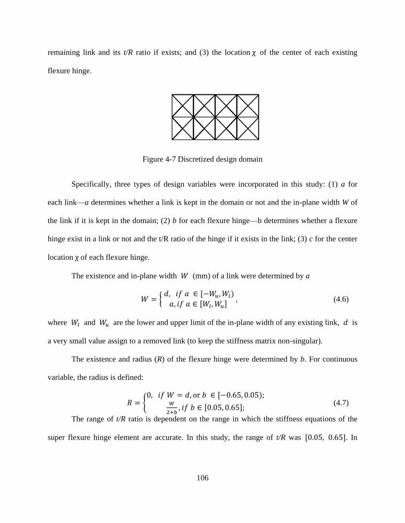
106
remaining link and its t/R ratio if exists; and (3) the location χ of the center of each existing
flexure hinge.
Figure 4-7 Discretized design domain
Specifically, three types of design variables were incorporated in this study: (1) a for
each link—a determines whether a link is kept in the domain or not and the in-plane width W of
the link if it is kept in the domain; (2) b for each flexure hinge—b determines whether a flexure
hinge exist in a link or not and the t/R ratio of the hinge if it exists in the link; (3) c for the center
location χ of each flexure hinge.
The existence and in-plane width 𝑊 (mm) of a link were determined by a
𝑊 = { 𝑑, 𝑖𝑓 𝑎 ∈ [−𝑊𝑢,𝑊𝑙)
𝑎, 𝑖𝑓 𝑎 ∈ [𝑊𝑙 ,𝑊𝑢] , (4.6)
where 𝑊𝑙 and 𝑊𝑢 are the lower and upper limit of the in-plane width of any existing link, 𝑑 is
a very small value assign to a removed link (to keep the stiffness matrix non-singular).
The existence and radius (R) of the flexure hinge were determined by b. For continuous
variable, the radius is defined:
𝑅 = {0, 𝑖𝑓 𝑊 = 𝑑, or 𝑏 ∈ [−0.65, 0.05);
𝑊
2+𝑏, 𝑖𝑓 𝑏 ∈ [0.05, 0.65];
(4.7)
The range of t/R ratio is dependent on the range in which the stiffness equations of the
super flexure hinge element are accurate. In this study, the range of t/R was [0.05, 0.65]. In

107
addition, a flexure hinge does not exist (R=0) if the link does not exist or 𝑏 ∈ [−0.65, 0,0.5). A
link without a hinge was modeled as three beam elements of length L/3.
The location of the center of a flexure hinge on a link is determined by c
χ = 𝑐, 𝑐 ∈ [0.1, 0.9], (4.8)
where χ represents the ratio of the distance from the first end point of the link to the center of
the flexure hinge and the total length of the link. Ideally, χ ranges from 0 to 1 but it was limited
from 0.1 to 0.9 to avoid the interference between connected links on the hinge.
Finite element analysis. In the design process, a design is analyzed with linear finite
element analysis, using finite beam elements and the proposed super flexure hinge element
(Equation (4.5)). Specifically, if a link remains in the domain with a flexure hinge on it, the link
is modeled with two beam elements which are connected through a super flexure hinge element;
otherwise, the link is modeled with three beam elements of the same length.
Optimization algorithm. The optimization problems were solved using a genetic
algorithm in the Global Optimization Toolbox in Matlab [173]. The toolbox can solve the
optimization problems which have both continuous and discrete variables [133, 174].
4.5 Design Examples
Two examples were studied to verify the proposed method. The first example was to
design force inverters, and the second was to design displacement amplifiers. For each design
test, the program was run 20 runs. The size of population and number of optimization
generations for each run were 100 and 150, respectively, and each run gave one result (20 runs
gave 20 results). For each design test, the best design is selected out of the 20 results.
In the first example, the goal was to design a force inverter to get a maximum output
force for a given input force, i.e., maximum Mechanical Advantage (MA). Two design tests were

108
conducted. A force inverter with both beam elements and flexure hinge elements was designed
and verified using ANSYS. Then, a force inverter with only beam elements was also designed
for comparisons.
In the second example, a displacement amplifier was designed using more beam elements
and more flexure hinge elements. The effect of link widths and the effect of hinge radii on final
designs were also investigated.
4.5.1 Example 1: Force Inverter
A force inverter is a mechanism used to change the direction of a force. Figure 4-8a
shows a square domain where a force inverter is assumed to be. Given a force at the input port in
the negative horizontal direction, the inverter will deflect, generating an output force in the
positive horizontal direction on the spring at the output port. The spring, with constant stiffness,
was employed to model the behavior of a work-piece. A spring at the output port ensures the
force transfer capability of a design [48]. The design domain and loadings were symmetric
(Figure 4-8a). Thus, half of the design domain and the symmetric boundaries were employed for
the design (Figure 4-8b).
The main goal of a force inverter was to achieve a maximum output force for a given
input force, i.e., to achieve a maximum MA. MA is the ratio of the output force to the input force.
In the study, the MA was negative. Thus, to maximize the magnitude of MA, we need to
minimize MA. The formulation was to
Minimize MA
Subject to: 𝐾𝑈 = 𝐹; 𝑢𝑖𝑛≤𝑢𝑖𝑛∗ ;
𝑎𝑖 = [−1,1], 𝑏𝑖 ∈ [−0.65,0.65], 𝑐𝑖 ∈ [0.1,0.9], i=1,2,…,n (4.9)

109
where K is the global stiffness matrix of the structure (including the spring); U is the
displacement vector, and F is the force vector. 𝑢𝑖𝑛 is the input displacement while 𝑢𝑖𝑛∗ is the
upper limit of the input displacement. A constraint on the input displacement was applied to
ensure small deformation so that linear finite element analysis is applicable. 𝑎𝑖 , 𝑏𝑖 , 𝑐𝑖 are the
design variables. n is the number of links. Table 4-3 presents the design parameters for the
design.
Figure 4-8 Design domain for the force inverter design
Table 4-3 Design parameters for example 1 and example 2
Young’s modulus 𝑃𝑖𝑛 𝑊𝑢 𝑢𝑖𝑛∗ Out-of-plane depth 𝐾𝑠
Example 1 2 GPa 1 N 1 mm 2 mm 1 mm 1000 N/m
Example 2 105 Gpa 1N 1 mm 2 mm 2 mm 1000 N/m
Figure 4-9a shows the obtained force inverter (the best one among 20 runs) and its nodal
displacement contour in ANSYS. The force inverter was analyzed using beam elements and
flexure hinge elements, and it was also analyzed using PLANE82 elements in ANSYS. The
obtained displacements are listed in Table 4-4. The relative errors between the two sets of results
are 0.04% and 0.29% for 𝑢𝑖𝑛 and 𝑢𝑜𝑢𝑡, respectively. It means that the proposed super flexure
hinge element is accurate. To be noted that in ANSYS, 34454 PLANE82 elements were used
while only three super flexure hinge elements and six beam elements were required to model this
Input Spring
?
40 mm
(a) (b)
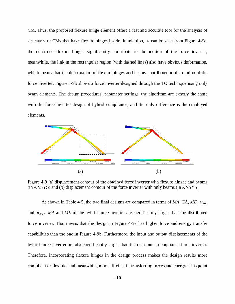
110
CM. Thus, the proposed flexure hinge element offers a fast and accurate tool for the analysis of
structures or CMs that have flexure hinges inside. In addition, as can be seen from Figure 4-9a,
the deformed flexure hinges significantly contribute to the motion of the force inverter;
meanwhile, the link in the rectangular region (with dashed lines) also have obvious deformation,
which means that the deformation of flexure hinges and beams contributed to the motion of the
force inverter. Figure 4-9b shows a force inverter designed through the TO technique using only
beam elements. The design procedures, parameter settings, the algorithm are exactly the same
with the force inverter design of hybrid compliance, and the only difference is the employed
elements.
Figure 4-9 (a) displacement contour of the obtained force inverter with flexure hinges and beams
(in ANSYS) and (b) displacement contour of the force inverter with only beams (in ANSYS)
As shown in Table 4-5, the two final designs are compared in terms of MA, GA, ME, 𝑢𝑖𝑛,
and 𝑢𝑜𝑢𝑡. MA and ME of the hybrid force inverter are significantly larger than the distributed
force inverter. That means that the design in Figure 4-9a has higher force and energy transfer
capabilities than the one in Figure 4-9b. Furthermore, the input and output displacements of the
hybrid force inverter are also significantly larger than the distributed compliance force inverter.
Therefore, incorporating flexure hinges in the design process makes the design results more
compliant or flexible, and meanwhile, more efficient in transferring forces and energy. This point
(b) (a)

111
satisfies the stiffness-flexibility criteria for CMs. However, it was also noticed that the stress of
the force inverter in Figure 4-9a is much higher than that of the one in Figure 4-9b, which means
the latter has a larger motion range before yield failure. This is because no criterion on stress
control was considered in the design formulation. However, while in the motion range of former
inverter, the hybrid design (with beams and flexure hinges) renders a mechanism with better
efficiency in transferring motion, force, or energy than the mechanism with only beams. In
addition, to accurately capture the stress of a flexure hinge using the super flexure hinge element,
the stress concentration effects have to be considered. The abrupt area reduction in the thin
region of a flexure hinge results in a localized increase in stress, causing the actual maximum
stress to be significantly larger than that predicted by elementary mechanics of materials
equations [161].
Table 4-4 Analysis result comparison
Displacement ANSYS result Result using beam and flexure hinge elements Relative error
𝑢𝑖𝑛 -0.9983mm -0.9987 mm 0.04%
𝑢𝑜𝑢𝑡 0.8942mm 0.8968 mm 0.29%
Table 4-5 Comparisons between distributed design and hybrid design
Terms Beam-only Beams and flexure hinges Improvement
|MA| 0.6431 0.8968 39.5%
|GA| 0.8889 0.8979 1.0%
ME 0.5717 0.8052 40.8%
|𝑢𝑖𝑛| 0.7235 mm 0.9987 mm 38.0%
|𝑢𝑜𝑢𝑡 | 0.6431 mm 0.8968 mm 39.5%
4.5.2 Example 2: Displacement Amplifier
A displacement amplifier is a mechanism that amplifies displacements. Displacement
amplifiers have been widely used for actuators such as PZT stack actuators that have short

112
strokes. As shown in Figure 4-10a, the actuator drives an amplifier with a displacement 𝑢𝑖𝑛 at
the input ports; then the amplifier undergoes a displacement 𝑢𝑜𝑢𝑡 at the output ports; meanwhile,
there are also resistance forces 𝑃𝑒𝑥𝑡 from external loads at the output ports. Since the design
domain and loadings are symmetric, only one quarter of the design domain were employed for
the design, as shown Figure 4-10b. Figure 4-10c shows the discretization of the design domain.
The design goal for a displacement amplifier is to achieve a large amplification ratio, that
is, a large magnitude of GA. To maximize the magnitude of GA, GA needs to be minimized in
the study since GA is negative due to the desired directions.
Minimize GA
Subject to: 𝐾𝑈 = 𝐹; 𝑢𝑖𝑛≤𝑢𝑖𝑛∗ ;
𝑎𝑖 = [−1,1], 𝑏𝑖 ∈ [−0.65,0.65], 𝑐𝑖 ∈ [0.1,0.9], i=1,2,…,n (4.10)
Table 4-3 shows the design parameters for example 2. Figure 4-11 shows the obtained
displacement amplifier (the best one among 20 results) and its nodal displacement contour in
ANSYS. The analysis results using super flexure hinge elements and ANSYS are compared in
Table 4-6. The maximum error between results from the two approaches is 6.46%, which further
demonstrates that the proposed flexure hinge model is accurate enough to analyze CMs that have
flexure hinges inside and the proposed TO technique is effective to design these mechanisms.
Figure 4-12 shows the full drawing of the displacement amplifier with an actuator.

113
Figure 4-10 Design domain for the displacement amplifier
Figure 4-11 Displacement contour of the displacement amplifier (one quarter) in ANSYS
𝑢𝑖𝑛 𝑢𝑖𝑛
𝑢𝑜𝑢𝑡
𝑢𝑜𝑢𝑡
𝑃𝑒𝑥𝑡
𝑃𝑒𝑥𝑡
Design
domain
Actuator
(a)
(b)
21 mm
30 mm
14 mm
20 mm
(c)

114
Table 4-6 Analysis result comparison
Terms ANSYS results Results using beam & flexure hinge elements Relative error
𝑢𝑖𝑛 -2.16 µm -2.30 µm 6.46%
𝑢𝑜𝑢𝑡 32.08 µm 32.39 µm 0.96%
|GA| 14.83 14.07 5.16%
Figure 4-12 A displacement amplifier (GA = 14.07)
4.5.3 Effects of Link Widths
In the subsection we investigate the effects of link widths. The amplifier design problem
was solved using links of different in-plane widths to study the effects of different link widths on
the mechanical characteristics of designs, i.e., 𝑢𝑖𝑛, 𝑢𝑜𝑢𝑡, GA, MA, and ME.
Six design cases with different link widths were studied, as shown in Table 4-7. Each
case was solved by running the program 20 times; thus, a group of 20 designs were obtained for
each case. In each group, the average and maximum performance, and the performance of the
best designs (designs with largest magnitudes of GA) were compared. Figure 4-13 shows the
performance of the designs and shows that, by increasing link widths, the magnitudes of GAs of
the best designs in D1-D5 tend to gradually increase while the MAs and MEs tend to gradually
decrease. The average of each design group also has similar trend. This means that by increasing
link widths, the best designs tend to be more capable of amplifying displacements but less
capable of transferring forces and energy. This is different from our intuition, i.e., with wider

115
links, the design tends to be more rigid and more energy efficient. The reason for this
counter-intuitive result may be attributed to the consideration of flexure hinges in designs. The
best and average designs in D6 have smaller GAs than those in D5 but larger GAs than those in
D1-D4. It means that, by considering the link widths as continuous design variables, we may not
get better results. In fact, all the links in the best design of D5 have the tendency to reach the
upper limit of widths, i.e., 1.5 mm. It means that the design tends to use the links of larger widths
for maximum geometric advantage.
Table 4-7 Link widths W (mm) in the six design cases
D1 D2 D3 D4 D5 D6
0.50 0.75 1.00 1.25 1.50 0.50 to 1.50
Figure 4-13 Performance of all the designs in the six design cases

116
4.5.4 Effects of the Radii of Flexure Hinges
In this subsection, the amplifier design problem was solved using flexure hinges of
different radii to study the effects of hinge radii on the performance of designs, i.e., 𝑢𝑖𝑛, 𝑢𝑜𝑢𝑡,
GA, MA, ME.
Table 4-8 Radii of existing hinges in the seven design cases
D1 D2 D3 D4 D5 D6 D7
0.5 0.6 0.7 0.8 0.9 1.0 0.5 to 1.0
As shown in Table 4-8, seven design cases with different hinge radii were investigated.
Each case was solved by running the program for 20 times; thus, a group of 20 designs were
obtained for each case. In each group, the average and maximum mechanical characteristics, the
mechanical characteristics of the best designs (designs with largest magnitudes of GA) were
compared. Figure 4-14 shows the performance of all the designs, and Figure 4-15 shows the best
design in D7.
As can be seen from Figure 4-14, with the increase of radii of flexure hinges in D1-D6,
the average performance of the designs also gradually increases. That means, the designs are
more flexible to deform and more efficient to transfer motions, forces and energy. Thus, with the
hinges of larger radius (thinner hinges), better results are more likely to be obtained. In addition,
as can be seen, the best design among all the designs was obtained in D7, where the radii of
hinges were considered as continuous design variables. It indicates that larger radii are not
always the only choices to generate better results; in fact, in a CM, some regions need thick
flexure hinges while some other regions may need thinner flexure hinges, i.e., the compliance are
various over the design domain. In addition, as can be seen from Figure 4-15, both flexure hinges
and long links exist, which makes the CM hybrid in terms of compliance although on a low level

117
of hybridization. Although it is more accurate to define compliance distribution in terms of
“stress distribution” [100]. We initiate our work by focusing on the force-deflection relationship,
which is the most significant characteristic of CMs. Stress distribution over the members of CMs,
although important, is the secondary characteristic. Moreover, with our framework as a
foundation, one can further control and investigate how stress is distributed over beams or
flexural hinges in a CM, then, come up with a more appropriate formulation for the design of
hybrid CMs. To do so, the stress concentration effects in flexure hinges have to be considered.
Figure 4-14 Performance of all design cases (D1-D7)

118
Figure 4-15 Displacement amplifier with an actuator (W = 1.5 mm and GA=18.41)
4.6 Conclusions
In this paper, a new type of finite element, i.e., super flexure hinge element, was
incorporated with the beam elements in the ground structure approach of TO techniques to
design hybrid CMs. The effects of the location and size of a flexure hinge in a compliant lever
was also investigated. Two design examples, force inverter design and displacement amplifier
design were presented to verify the proposed method.
Flexure hinges are complicated in geometry due to its varying cross sections so that the
numerical analysis is often computationally costly. The defined super flexure hinge element, as
verified using ANSYS, makes the analysis of flexure hinges efficient and accurate. By
integrating super flexure hinge elements and beam elements, both the analysis and synthesis of
hybrid CMs become efficient and accurate.
Using the super flexure element, the effects of the location and size of a flexure hinge in a
simple CM was investigated. These results explain why point flexures are often in TO results
when the stiffness-flexibility criteria are formulated as objective functions—a point flexure,
similar as a flexure hinge, improves the flexibility and stiffness of a design.
Super flexure hinge elements and classic beam elements were incorporated to develop a
new TO technique in this study. Design results demonstrated that the proposed framework is

119
effective for the design of hybrid CMs and incorporating flexure hinges greatly improves the
performance of designs. The effects of in-plane widths of links and radii of hinges were also
investigated. It was shown that improved results can be obtained by controlling link widths and
hinge radii.
It is also noted that the design results are hybrid in terms of compliance only on a low
level. This is because the employed TO formulation does not have control on the
stress/compliance distribution of CMs and might not naturally lead to hybrid CMs with proper
integration of lumped compliance and distributed compliance; thus, a future work is to develop
more appropriate formulations from the perspective of stress distribution to better utilize flexure
hinges and beams in hybrid CMs.
Appendix: Stiffness Equations
In this paper, the employed equations for 𝑘𝑥 and 𝑘𝑦 are from [168], and the equation
for 𝑘𝛼 is from [169]. These three equations are listed below:
𝑘𝑥 = 𝐸 ∙ 𝑑 ∙ ∑ 𝑐𝑖 (𝑡
𝑅)𝑖
𝑛𝑖=0 (4.11)
𝑘𝑦 = 𝐸 ∙ 𝑑 ∙ ∑ 𝑐𝑖 (𝑡
𝑅)𝑖
𝑛𝑖=0 (4.12)
𝑘𝛼 =𝐸∙𝑑∙𝑡2
12[−0.0089 + 1.3556√
𝑡
2𝑅− 0.5227(√
𝑡
2𝑅)
2
] (4.13)
where E is the Young’s Modulus of the material, d is the out-of-plane depth of the flexure hinge,
t is the in-plane thickness of the thinnest section of the flexure hinge, R is the radius of the
circular shape the flexure hinge, and 𝑐𝑖 are the coefficients listed in Table 4-9.

120
Table 4-9 Coefficients (𝑐𝑖) of the polynomial functions in the equations for 𝑘𝑥 and 𝑘𝑦 [168]
Coefficients 𝑘𝑥 (fifth order) 𝑘𝑦 (sixth order)
𝑐0 0.036343 1.92× 10⁻⁵
𝑐1 0.98683 -0.00083463
𝑐2 -1.5469 0.021734
𝑐3 3.1152 0.064783
𝑐4 -3.0831 -0.088075
𝑐5 1.2031 0.062278
𝑐6 / -0.018781
Acknowledgements
The first author acknowledges the financial support from the China Scholarship Council.
This research is also partially supported by NSERC Discovery Grant to the corresponding author.

121
CHAPTER 5
DESIGN OF HYBRID COMPLIANT MECHANISMS THROUGH TOPOLOGY
OPTIMIZATION WITH AN INPUT STROKE CRITERION
Chapter 5 presents the second study for Objective 2. In the previous chapter, beams and
flexure hinges are incorporated to initialize the design domain in TO, and the design results with
both beams and flexure hinges are obtained. However, the design results are highly lumped in
compliance and thus are energy efficient but not strong; this result is because only the
stiffness-flexibility criteria are considered in the optimization formulation and thus is no
preference for distributed compliance in the optimization formulation. In this chapter, an input
stroke criterion, representing the requirement on the allowable input displacement before yield
failure of CMs, is incorporated with the stiffness-flexibility criteria into the optimization
formulation. The input stroke criterion provides a better control over the stress distribution of
CMs during TO. With the formulation based on the three criteria, i.e., stiffness, flexibility, and
input stroke criteria, and also the parameterization using beam elements and super flexure hinge
elements, strong and efficient CMs are obtained.
The work presented in this chapter is included in the following manuscript:
Cao, L., Dolovich, A., and Zhang, W. J., 2014, “Hybrid Compliant Mechanism Design
through Topology Optimization with an Input Stroke Criterion”, ASME Journal of Mechanisms
and Robotics, submitted as Research Paper, under review, manuscript ID: JMR-14-1345.
Abstract
Designing a CM that can efficiently transfer motion, force, or energy while being
sufficiently strong to resist yield or fatigue failure is a challenge. Using distributed CMs is

122
traditionally a primary approach to achieving strong CMs as a distributed CM generally exhibits
a lower stress level as opposed to a lumped CM. However, a distributed CM has the shortcoming
of lower energy transfer efficiency. This paper presents the following contributions to the design
of CMs. First, a new design philosophy with topology optimization toward hybrid CMs is
proposed for. Such a hybrid CM consists of both flexure hinges and beams and may benefit from
their complementary inherent properties in stress distribution and energy efficiency. Second, a
new design criterion is proposed—a CM should have a sufficiently large input stroke without
yield failure. With the proposed new philosophy and new criterion, the proposed topology
optimization technique can properly integrate lumped compliance and distributed compliance.
Both theoretical explorations and design examples are presented to show the effectiveness of the
proposed approach. As a natural derivation of this study, two findings are made (1) a lumped CM
may not necessarily have a poor stress situation and (2) a distributed CM may not necessarily
have a large input stroke. These findings strongly support the need of research to new approaches
to the design of CMs, such as the one presented in this paper.
5.1 Introduction
A CM gains at least part of its mobility from the deformation of its flexible component(s)
[2]. Using CMs as a solution to mechanical tasks may lead to the advantages such as reduced
cost (reduced parts and simplified fabrication process) and improved performance (improved
precision and reduced maintenance). CMs have attracted significant attention in recent years due
to these advantages and have been utilized in various applications such as precision stages [18,
19, 175, 176], MEMS [14, 22], and biomedical devices [24, 25].
Similar to rigid-body mechanisms, CMs are used to transfer motion, force, or energy.
However, the performance of CMs is inherently limited because CMs require a fraction of the

123
input energy to deform parts, thereby reducing the energy transfer efficiency. Furthermore, the
stress distribution in CMs has significant effects on the performance of CMs; poorly designed
CMs may have high localized stresses (i.e., stress concentration), making them prone to yield or
fatigue failure. As a result, the challenge is to design CMs that are efficient in motion and force
transfer and energy utilization while at the same time strong enough to resist failure. The goal of
the study presented in this paper was to tackle this challenge.
A widely used synthesis approach to CMs is TO [38, 47, 48, 82, 97, 165]. In TO, two
design criteria are often considered: a CM should be sufficiently flexible to be deformed to
transfer motion and be sufficiently stiff to transfer force or bear external loads. The two criteria
are the so-called stiffness-flexibility criterion that has been widely used [38, 40, 44, 45, 48, 77,
97]. This stiffness-flexibility criterion has been formulated into many optimization formulations
such as the ratio of the mutual strain energy and the strain energy [40, 77], MA, GA, and ME [44,
45]. These formulations, despite different forms, all converge to designs that deliver the
maximum output energy through the output ports but store the minimum strain energy in the
elastic bodies. In other words, these formulations often lead to lumped CMs, or even CMs with
undesirable point flexures [48, 49] that are efficient in transferring motion, force or energy but
suffer from localized high stress.
Many strategies have been developed to avoid lumped CMs (or CMs with point flexures)
[49, 51, 53] and to get more distributed CMs that exhibit lower stress levels and larger motion
ranges than lumped CMs [49, 82, 99]. Krishnan et al. [100] quantified the distribution of
compliance as a metric to facilitate the size optimization of distributed CMs. However,
distributed CMs may not be a good solution in all cases because a distributed CM has the
weakness of lower energy utilization efficiency than its lumped counterpart. Therefore, when
124
both the energy efficiency and stress levels are the concerns of the design requirements, a CM
with a mixture of lumped compliance and distributed compliance may be a good structural
choice; this CM consists of components with complementary mechanical properties in stress
distribution and energy efficiency, and these components are rationally located and sized so that
the CM may be efficient and strong. Such a CM can be also called as a hybrid CM. Refer to [103,
177] for hybrid CMs that were designed by taking advantage of different complementary
properties (other than stresses and efficiency) of their components. Furthermore, regardless of
how to avoid point flexures or how to distribute compliance, one cannot forget that the ultimate
goal is to produce CMs that allow sufficiently large input displacement prior to yield failure.
Therefore, it is reasonable to consider a new design criterion—large enough input stroke (large
enough input displacement before yield failure)—to constrain the searching process for CMs.
This new criterion is called input stroke criterion hereafter.
The design philosophy in this study was to design hybrid CMs, governed by the proposed
input stroke criterion and the stiffness-flexibility criterion. Flexure hinges and slender beams
were considered as the constructive units of a hybrid CM. Note that (1) a flexure hinge mimics a
revolute joint and tends to bring lumped compliance to a CM [64] and (2) a slender beam, if
properly used, tends to bend throughout its body and thus brings distributed compliance to a CM.
Therefore, the proposed approach integrates lumped compliance and distributed compliance for
hybrid CM design from the perspectives of both design criteria and physical constructions.
In the following, the input stroke metric is presented in Section 5.2 where the metric for
compliance distribution defined by Krishnan et al. [100] is also introduced. In Section 5.3, a
super flexure hinge element is developed to model the force-deflection relationship and stress
(with stress concentrations factors being considered) of flexure hinges. The element is then

125
verified through simulations using ANSYS. In Section 5.4, the effects of the location and size of
a flexure hinge in a simple CM are investigated. In Section 5.5, the proposed TO technique is
introduced. Section 5.6 presents six design tests for compliant displacement amplifiers.
Krishnan’s metric for compliance distribution and the input stroke metric are also compared and
commented. Section 5.7 concludes the paper.
5.2 Compliance Distribution and Input Stroke
Based on the concept of fully stressed design [178], Krishnan et al. [100] quantified the
distribution of compliance by proposing a metric 𝑛𝑝 which is the ratio of the average strain
energy density experienced by the entire material volume to the maximum strain energy density
experienced at a local region with the highest stress magnitude. In this study, 𝑛𝑝 was calculated
as [100]
𝑛𝑝 =(𝑓𝑖𝑛𝑢𝑖𝑛−𝐾𝑠𝑢𝑜𝑢𝑡
2 )𝐸
𝜎𝑣,𝑚𝑎𝑥2 ×𝑉
, (5.1)
where 𝑢𝑖𝑛 and 𝑢𝑜𝑢𝑡 are the input and output displacements of a CM, respectively, when an
input force 𝑓𝑖𝑛 is applied at the input port and a spring of stiffness 𝐾𝑠 is attached at the output
port. 𝜎𝑣,𝑚𝑎𝑥 is the maximum von-Mises stress, and 𝑉 is the total volume of material used in a
CM. The metric essentially represents the fraction of the material volume that is maximally
utilized to bear loads or stresses. The metric also indicates the amount of work that can be
performed on the material for a given maximum permissible stress. The logic behind this
definition is that the more the material is evenly stressed, the more distributed the compliance is.
The maximum allowable input stroke of a CM is
𝑈𝑖𝑛,𝑠 =𝜎𝑦
𝜎𝑣,𝑚𝑎𝑥𝑢𝑖𝑛, (5.2)

126
where 𝜎𝑦 is the yield strength of material, and 𝑢𝑖𝑛 is the input displacement of a CM under a
specified input force. The metric 𝑈𝑖𝑛,𝑠 is the maximum allowable input displacement of a CM
before its maximum von-Mises stress reaches the yield strength of the material. This metric is
proposed for the linear elastic property and small deformation analysis. However, this metric is
also qualitatively applicable to large deformation problems because the metric indicates the
stress cost per input motion regardless of whether the motion is large or small: a large 𝑈𝑖𝑛,𝑠
indicates a low stress cost per input displacement.
5.3 Super Flexure Hinge Element
In this section, a super flexure hinge element is introduced to model a commonly used
type of flexure hinges—circular flexure hinges [103, 177].
Figure 4-2a shows a two-dimensional circular flexure hinge whose stiffness properties in
three directions are essential: the rotational stiffness 𝑘𝛼 (𝑀𝛼 𝛼)⁄ and the translational stiffness
components 𝑘𝑥 (𝐹𝑥 ∆𝑥⁄ ) and 𝑘𝑦 (𝐹𝑦 ∆𝑦⁄ ). The equations for these stiffness properties can be
found in [169-172]. The accuracy of these equations highly depends on the t/R ratio (t is the
in-plane thickness of the thinnest region of a hinge, and R is the radius of a hinge) [168]. In our
case, the equations should be accurate over a wide range of the t/R ratio. The rotational stiffness
equation 𝑘𝛼 in [169] was used because it is the most accurate one (average error is 1.2%
compared to the results from ANSYS) with the widest range of the t/R ratio (0.05 ≤t/R≤ 0.65)
compared to other equations. The empirical equations in [168] (based on the ANSYS results)
were used for the translational stiffness equations of 𝑘𝑥 and 𝑘𝑦. The average errors of the
equations of 𝑘𝑥 and 𝑘𝑦, with the t/R ratio in the range of 0.5 to 0.8, are 0.07% and 0.08%,
respectively. The three stiffness equations were further used to derive the stiffness matrix of the

127
super flexure hinge element. Refer to the Appendix for the details of the derivation and the
obtained stiffness matrix.
5.3.1 Von-Mises Stress with Stress Concentration Factors
The abrupt area reduction in the thin region of a flexure hinge results in a localized
increase in stress, causing the actual maximum stress to be significantly larger than that predicted
by the elementary mechanics of materials equations [179]. A quantitative metric of the stress
increase is the stress concentration factor, which is the ratio of the maximum stress to the
nominal stress (or the reference stress); therefore, in the super flexure hinge element, its stress
concentration factor can be used to estimate the actual maximum stress from the nominal stress
in the element. This stress concentration factor is dependent solely on the geometry of the notch
region and the type of loading [179]. The equation for the von-Mises stress is
𝜎𝑉 = √𝜎𝑥𝑥2 + 3𝜏𝑥𝑦
2 (5.3)
where 𝜎𝑥𝑥 and 𝜏𝑥𝑦 are the normal stress and the shear stress, respectively. The in-plane loads
of a flexure hinge consist of the axial force 𝐹𝑥, the pure bending moment 𝑀𝛼, and the transverse
force 𝐹𝑦. The axial force (𝐹𝑥) and the resultant bending moment 𝑀 (caused by 𝑀𝛼 and 𝐹𝑦)
result in normal stresses, and the transverse force 𝐹𝑦 results in shear stresses. In flexure hinges
𝑀𝑗𝛼
𝐹𝑖𝑥
𝐹𝑖𝑦
𝑀𝑖𝛼
i
𝐹𝑗𝑦
𝐹𝑗𝑥 j
𝐹𝑗𝑦
𝐹𝑗𝑥 j
𝑀𝑗𝛼
𝐹𝑖𝑦
𝑀𝑖𝛼
i
(b) (a)
Figure 5-1 (a) a circular flexure hinge, (b) the super flexure hinge element

128
and slender beams, shear stresses are negligible because normal stresses are more dominant than
shear stresses.
In a flexure hinge, the maximum normal stress due to the resultant bending moment 𝑀
(caused by 𝑀𝛼 and 𝐹𝑦) occurs at the lower or upper bound (y = ±𝑡 2⁄ ) of the thinnest section
(𝑥 = 𝑅):
𝜎𝑚𝑎𝑥𝑏 = 𝑘𝑐𝑠,𝑏𝜎𝑛𝑜𝑚
𝑏 , (5.4)
where 𝜎𝑛𝑜𝑚𝑏 is the nominal maximum bending stress and 𝑘𝑐𝑠,𝑏 is the stress concentration factor
for bending. 𝜎𝑛𝑜𝑚𝑏 is calculated by
𝜎𝑛𝑜𝑚𝑏 =
6𝑀
𝑏𝑡2=
6(𝑀𝛼+𝐹𝑦𝑅)
𝑏𝑡2, (5.5)
where 𝑏 is the out-of-plane width of the flexure hinge.
From [179], the stress concentration factor for bending is calculated by
𝑘𝑐𝑠,𝑏 =𝑅 𝑡⁄ +0.188
𝑅 𝑡⁄ +0.014 (5.6)
The maximum normal stress due to the axial force 𝐹𝑥 is
𝜎𝑚𝑎𝑥𝑥 = 𝑘𝑐𝑠,𝑥𝜎𝑛𝑜𝑚
𝑏 , (5.7)
where 𝑘𝑐𝑠,𝑥 is the stress concentration factor for the axial force 𝐹𝑥, and 𝜎𝑛𝑜𝑚𝑥 is the nominal
maximum tensile or compressive stress caused by the axial force 𝐹𝑥:
𝜎𝑛𝑜𝑚𝑥 =
𝐹𝑥
𝑤𝑡 (5.8)
From [179], the stress concentration factor for the axial force is calculated by
𝑘𝑐𝑠,𝑥 =𝑅 𝑡⁄ +0.335
𝑅 𝑡⁄ +0.035 (5.9)
Thus, the maximum von-Mises stress is
𝜎𝑉,𝑚𝑎𝑥 = 𝜎𝑚𝑎𝑥𝑥 +𝜎𝑚𝑎𝑥
𝑏 = 𝑘𝑐𝑠,𝑥𝜎𝑚𝑎𝑥,𝑥 + 𝑘𝑐𝑠,𝑏𝜎𝑚𝑎𝑥,𝑏. (5.10)

129
5.3.2 Model Verification
Two examples are used to verify the equations for the stiffness matrix and the maximum
von-Mises stress of the super flexure hinge element.
Example 1. Figure 5-2a shows two beams connected through a flexure hinge. The left
end of the structure is clamped, while the right end is loaded with an axial force 𝐹x and a
transverse force 𝐹y. The specifications of the structure are listed in Table 5-1.
The structure is analyzed using two beam elements (𝑒1 and 𝑒3) and the proposed super
flexure hinge element (𝑒2), as shown in Figure 5-2b. ANSYS is also used to analyze the structure.
A mapped meshing technique is used to mesh the structure for better control over the elements
(PLANE82) and nodes, as seen from Figure 5-2c. Sensitivity analysis (mesh refinement and
different material and input forces) was performed to ensure the analysis results were not
mesh-dependent. Analysis and comparisons are conducted by varying the t/R ratio from 0.05 to
1.5, with an increment of 0.01. Three terms are considered: the horizontal and vertical
displacements (𝑈3,𝑥 and 𝑈3,𝑦) of the point at the location of node 3 in Figure 5-2b and the
maximum von-Mises stress 𝜎𝑉,𝑚𝑎𝑥 of the structure. Node 3 is chosen because the cross section
at node 3 bears moments, vertical forces and horizontal forces, so that the stiffness matrix of the
flexure hinge element could be verified in all types of loadings.
Table 5-1 Specifications for verification
Young’s modules E 105 GPa
Poisson ratio 𝜇 0.33
Horizontal force 𝐹𝑥 100 N
Vertical force 𝐹𝑦 100 N
In-plane width W 10 mm
Out-of-plane depth 10 mm
Length of each link L 40 mm

130
Figure 5-2 Verification of the super flexure hinge element
(a)
(b)
R
L L
W 𝐹𝑥
𝐹𝑦
𝑒1 𝑒2 𝑒3
1 2
3 4
(c)
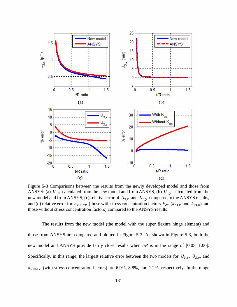
131
Figure 5-3 Comparisons between the results from the newly developed model and those from
ANSYS: (a) 𝑈3,𝑥 calculated from the new model and from ANSYS, (b) 𝑈3,𝑦 calculated from the
new model and from ANSYS, (c) relative error of 𝑈3,𝑥 and 𝑈3,𝑦 compared to the ANSYS results,
and (d) relative error for 𝜎𝑉,𝑚𝑎𝑥 (those with stress concentration factors 𝑘𝑐𝑠 (𝑘𝑐𝑠,𝑥 and 𝑘𝑐𝑠,𝑏) and
those without stress concentration factors) compared to the ANSYS results
The results from the new model (the model with the super flexure hinge element) and
those from ANSYS are compared and plotted in Figure 5-3. As shown in Figure 5-3, both the
new model and ANSYS provide fairly close results when t/R is in the range of [0.05, 1.00].
Specifically, in this range, the largest relative error between the two models for 𝑈3,𝑥, 𝑈3,𝑦, and
𝜎𝑉,𝑚𝑎𝑥 (with stress concentration factors) are 6.9%, 8.8%, and 1.2%, respectively. In the range
(a) (b)
(c) (d)
132
of (1.00, 1.50], the errors for both 𝑈3,𝑦 and 𝜎𝑉,𝑚𝑎𝑥 are fairly small as well, but that for 𝑈3,𝑥
increases to 16.9%. These comparisons suggest that the stiffness matrix and the stress
concentration factors of the super flexure hinge element are accurate when the t/R is in the range
of [0.05, 1.00].
In addition, as shown in Figure 5-3d, the error would be notably large (up to 20.9%) if the
stress concentration factors are not considered in the calculation of 𝜎𝑉,𝑚𝑎𝑥 . This result
demonstrates the effect of stress concentration and suggests the necessity to consider stress
concentration factors for the calculation of 𝜎𝑉,𝑚𝑎𝑥.
Example 2. A flexure-based displacement inverter is also analyzed using beam elements
and super flexure hinge elements. The results are compared to the ANSYS results. Figure 5-4a
shows the inverter analyzed using the new model and using ANSYS. Due to the symmetrical
geometry, only the upper-half of the inverter is shown and analyzed. The parameters of the
inverter are listed in Table 5-2. In addition, the hinge on link I is in the middle of the link, and
the two hinges on link II (and III) locate at one quarter and three quarters of the length of the link,
respectively.
Table 5-2 Parameters of the inverter
Young’s modulus 1.4 GPa
Input force Fin 1 N
Radius R of all hinges 2 mm
In-plane width of the links 6 mm
Out-of-plane width 5 mm
L 40 mm
Table 5-3 lists the input/output displacements and the maximum von-Mises stresses
calculated from the hinge-based model and from ANSYS. These calculated results are all fairly

133
close, which means the super flexure hinge element are accurate enough for deformation and
stress analysis of flexure-based CMs.
Figure 5-4 Displacement amplifier (the displacement is scaled 30 times up): (a) the initial shape
and the deformed shape that is analyzed through the beam elements and the super flexure hinge
element (8 beam elements and 5 hinge elements). The red dots indicate hinges, the green lines
denote beam elements, and the dashed line denotes the deformed shape of the inverter whose
location of the maximum von-Mises stress is indicated by a red dashed line section; (b) the initial
and deformed shape analyzed using ANSYS (4062 PLANE82 elements are used)
From the above two examples, it can be concluded that the super flexure hinge element is
accurate for the deformation and stress analysis of flexure-based CMs. Using super flexure hinge
elements can dramatically decrease the number of elements required, making it computationally
efficient. In this study, the super hinge element was incorporated in TO to design hybrid CMs.
(a)
L L
L
I
II
III
Fin
Input port Output port
(b)
MX
MN
MX

134
Table 5-3 Analysis results and comparisons with the results from ANSYS
Input displacement Output displacement 𝜎𝑉,𝑚𝑎𝑥
ANSYS 0.1153 mm -0.1079 mm 4.5829 MPa
New model 0.1187 mm -0.1118 mm 4.5976 MPa
Relative error 2.9% 3.6% 0.3%
5.4 A Simple Compliant Mechanism
Traditional formulations such as the ratio of the mutual strain energy and the strain
energy, MA, GA and ME in TO all similarly seek to transfer as much energy, force, or motion as
possible from the input port to the output port of a CMs. Flexure hinges are fairly efficient in
transferring energy, force, or motion. Thus, TO algorithms using these traditional formulations
often result in CMs with point flexures or highly lumped CMs [53]. A lumped CM generally has
localized high stress and thus limited motion range before yield or fatigue failure. However, few
studies have studied the relationship between the criteria in these existing formulations and the
stress distribution of different designs. In this following, the relationship between the
performance and the design of a simple compliant lever is investigated.
Figure 5-5 (a) a compliant lever and (b) its rigid counterpart
Figure 5-5a shows a compliant lever that amplifies the input motion at the output port.
The output port is attached to a spring, which would apply a resistance force to the lever if
deformed. A flexure hinge is located between the input port and the left end of the lever. In
Input Input
𝜒 × 𝐿
𝐿 𝐿
(a) (b)
Output spring 𝐾𝑠
Output spring 𝐾𝑠

135
essence, the compliant lever mimics the function of the rigid lever shown in Figure 5-5b. The
parameters of the compliant lever are listed in Table 5-4.
The location of the flexure hinge on a link is determined by the generalized coordinate χ
(non-dimensional) of the hinge, which is the ratio of the distance from the first end point of the
link to the center of the flexure hinge and the total length of the link For instance, if the length of
the link is L (from the first end to the other end of the link), the hinge locates on the link and the
distance from first end to the center of the hinge is χ × 𝐿. In this investigation, five different
hinge locations were considered, i.e., 𝜒=0.25, 0.40, 0.55, 0.70, and 0.85. For each hinge location,
the t/R ratio of the hinge is varied from 0.05 to 1.00, with an increment of 0.01. Every set of
hinge location and t/R ratio represents a different lever design. Note that, with the specified
in-plane width of the link, increasing the t/R ratio of a flexure hinge on the link actually increases
the in-plane thickness t of the thinnest section of the flexure hinge and decreases the radius R of
the flexure hinge. Seven performance metrics are investigated: input displacement 𝑢𝑖𝑛 under the
specified input force, ME, GA, MA, maximum von-Mises stress 𝜎𝑣,𝑚𝑎𝑥 , 𝑛𝑝 proposed by
Krishnan et al. [100], and 𝑈𝑖𝑛,𝑠 proposed in the study. Figure 5-6 shows the performance
metrics of the compliant lever with different sizes and locations of hinges.
Table 5-4 Parameters of the compliant lever
Young’s modulus E 1.4 GPa
Input force Fin 1 N
𝐾𝑠 300 N/m
In-plane width W of the links 6 mm
Out-of-plane depth 5 mm
L 40 mm
By increasing t/R ratio (i.e., increasing t and decreasing R), 𝑢𝑖𝑛, MA, 𝑛𝑝, and 𝑈𝑖𝑛,𝑠
decrease while ME, GA, and 𝜎𝑣,𝑚𝑎𝑥 increase initially but then decrease. 𝑢𝑖𝑛 is large when the

136
hinge is thin (t/R ratio is small) because a thin hinge makes the system more flexible.
Encouragingly, when 𝑢𝑖𝑛 is at its maximum, 𝜎𝑣,𝑚𝑎𝑥 is at its minimum, which is different from
our intuition. Normally, if there is no output spring at the output port, the maximum 𝑢𝑖𝑛 always
corresponds to the maximum 𝜎𝑣,𝑚𝑎𝑥. However, when there is a spring at the output port, the
maximum 𝑢𝑖𝑛 does not necessarily correspond to the maximum 𝜎𝑣,𝑚𝑎𝑥. This behavior can also
be observed from the trends of 𝑛𝑝 and 𝑈𝑖𝑛,𝑠, which reaches maximum when the hinge is thin
and 𝑢𝑖𝑛 is large. Moreover, the lever is also energy efficient when the hinge is thin, as observed
from the relative high values of ME when the hinge is thin. Therefore, when the hinge is thin, the
lever has large input stroke (and well distributed compliance) and relatively high
energy-efficiency, which is desirable in the CM design. This result suggests that flexure hinges
are not always undesirable in CMs, even when the stress issues are concerned: flexure hinges
may make a CM energy-efficient without leading to a poor input stroke or poor compliance
distribution.
When the location of the hinge on the link changes from the left to the right (i.e., χ increases),
the lever becomes stiffer and thus 𝑢𝑖𝑛 decreases; the portion of energy that can be transferred to
the spring also decreases, i.e., ME decreases; this also decreases MA and 𝜎𝑣,𝑚𝑎𝑥 but increases
GA and 𝑛𝑝; 𝑈𝑖𝑛,𝑠 initially decreases and then increases. When the hinge is thin (t/R ratio is
small), the value of 𝑛𝑝 when the hinge is at the right end (χ = 0.85) is much higher than those
at other locations. In fact, the input stroke does not significantly change at all these locations.
Note that when the hinge is at the right end, the value of GA is relatively high, and 𝑛𝑝 and 𝑈𝑖𝑛,𝑠
achieve their maximums, which is desirable for a compliant amplifier.

137
Figure 5-6 Performance metrics of compliant levers with different hinge locations and t/R ratios: (a)
input displacement 𝑢𝑖𝑛 , (b) mechanical efficiency ME, (c) geometrical advantage GA, (d)
mechanical advantage MA, and (e) maximum von-Mises stress 𝜎𝑣,𝑚𝑎𝑥. (Continued)
(a) (b)
(c) (d)
(e)
χ = 0.25 χ = 0.40 χ = 0.55 χ = 0.70 χ = 0.85

138
Figure 5-6 Performance metrics of compliant levers with different hinge locations and t/R ratios: (f)
compliance distribution metric 𝑛𝑝, and (g) input stroke 𝑈𝑖𝑛,𝑠. (Continued from the previous page.)
In summary, if flexure hinges are properly sized and located in a CM, the CM may
exhibit good performance in terms of both input stroke and motion, force, or energy transfer
capabilities.
5.5 Topology Optimization
This section introduces the following aspects of the proposed TO: discretization of the
design domain, design variables, finite element analysis, and optimization algorithm. The
optimization formulation (objective functions and constraints) is application-specific and thus are
introduced in Section 5.6.1 where examples are presented.
Discretization. A hybrid CM consists of both segments of distributed compliance and
segments of lumped compliance. A slender beam, if properly used, tend to bend throughout its
body and thus brings distributed compliance to a CM. A flexure hinge mimics a revolute joint
and tends to bring lumped compliance to a CM [180]. Thus, beams of constant cross sections and
the widely used circular flexure hinges were considered as segments of distributed compliance
and segments of lumped compliance, respectively. Compared to other types of flexure hinges, a
(f) (g)

139
circular flexure hinge is accurate in rotational motion as the center of the rotational motion is
close to the center of the hinge [102, 168].
As shown in Figure 5-7, the design domain in this approach is discretized into a network
of straight links or beams (the green lines), and each straight link allows one flexure hinge (the
red dots) on it at most. Each link has three possible states during the design process: being
removed from the domain, staying in the domain without a flexure hinge on it, or staying in the
domain with a flexure hinge on it. The design task is to determine (1) which links are kept in the
domain and their in-plane widths 𝑊; (2) whether a flexure hinge exists on a remaining link and
its t/R ratio if it exists; and (3) the location or generalized coordinate χ of the center of each
existing flexure hinge on the link (refer to Section 5.4 for the detailed definition of χ).
Figure 5-7 Discretized design domain
Design variables. Three types of design variables were incorporated in this study: (1) a
for each link—a determines whether a link is kept in the domain or not and the in-plane width W
of the link if it is kept in the domain; (2) b for each flexure hinge—b determines whether a
flexure hinge exists in a link or not and the t/R ratio of the hinge if it exists in the link; (3) c for
the location of each flexure hinge, i.e., the generalized coordinate χ.
The existence and in-plane width 𝑊 (mm) of a link were determined by variable a
𝑊 = { 𝑑, 𝑖𝑓 𝑎 = −2,−1, or 0 𝑎, 𝑖𝑓 𝑎 = 1, 2, or 3
, (5.11)
where 𝑊 has three discrete possible values, 𝑑 is a very small value assign to a removed link
(to keep the stiffness matrix non-singular).

140
The existence and radius (R) of the flexure hinge were determined by b. For continuous
variable, the radius is defined:
𝑅 = {0, 𝑖𝑓 𝑏 ∈ [−1, 0.05); 𝑊
2+𝑏, 𝑖𝑓 𝑏 ∈ [0.05, 1];
(5.12)
The limits of t/R ratio are dependent on the range in which the stiffness equations of the
flexure hinge element are accurate. In this study, the range of t/R for accurate analysis was
deemed as [0.05, 1]. A flexure hinge does not exist (R=0) if 𝑏 ∈ [0,0.5). A link without a
hinge was modeled as three beam elements of length L/3.
The location of the center of a flexure hinge on a link is determined by c
χ = 𝑐, 𝑐 ∈ [0.25, 0.75], (5.13)
Ideally, ℎ𝑙 ranges from 0 to 1 but it was limited from 0.25 to 0.75. In practice, a flexure hinge
cannot be too close to the ends of the link; otherwise, there might be geometric interference on
the geometry of the hinge due to the other connected link.
Note that the ranges of these design variables are case-specific, and the designers can specify
these ranges based on their specific design problems.
Finite element Analysis. In the design process, a design is analyzed with linear finite
element analysis, using finite beam elements and the proposed super flexure hinge element
(Equations (4.5) and Equation (5.10)). Specifically, if a link remains in the domain with a flexure
hinge on it, the link is modeled with two beam elements which are connected through a super
flexure hinge element; otherwise, the link is modeled with three beam elements of the same
length.
Optimization algorithm. The optimization problems were solved using a genetic
algorithm in the Global Optimization Toolbox in Matlab [173]. The toolbox can solve the
optimization problems which have both continuous and discrete variables [133, 174], and this is
the case of the present study.

141
5.6 Synthesis Examples
5.6.1 Displacement Amplifier Design
The TO approach is demonstrated through a displacement amplifier design problem, as
illustrated in Figure 5-8a. An amplifier within the design domain (the grey region) undergoes a
displacement of 𝑢𝑜𝑢𝑡 at the output port (loaded with an external load 𝑃𝑒𝑥𝑡) in response to a
displacement 𝑢𝑖𝑛 due to the actuator at the input port, As shown in Figure 5-8b, only one
quarter of the design domain is considered because the design domain and loads for the amplifier
are symmetric. The one quarter of the design domain is then discretized into a network of
straight links (the green lines), and each straight link allows one flexure hinge (the red dots) on it
at most, as shown in Figure 5-8c. A unit force 𝐹𝑖𝑛 is applied at the input port, and a linear
spring is attached at the output port to model the resistance from the environment (the stiffness of
the spring is 𝐾𝑠). Table 5-5 lists the design specifications.
Two types of the objective functions were used separately in different design tests: the
first objective function is:
to minimize 𝑂𝑏𝑗𝐴 = −𝐺𝐴 = −𝑢𝑜𝑢𝑡 𝑢𝑖𝑛⁄ (5.14)
and the second objective function is:
to minimize 𝑂𝑏𝑗𝐵 = −1000 × sign(𝐺𝐴) × 𝐺𝐴2 × 𝑈𝑖𝑛,𝑠, (5.15)
where 𝑈𝑖𝑛,𝑠 is calculated based on Equation (5.2). By having a squared GA, more priority is
given to the criterion of GA than the input stroke criterion. A negative sign is added to both
objective functions. By minimizing the objective functions, GA and/or 𝑈𝑖𝑛,𝑠 in the positive
directions are actually maximized. In addition, all parameters in the formulations are expressed
based on the International System of Units. The objective functions are subject to the structural
equilibrium equations and the limits of the design variables. Every candidate design is checked

142
whether the regions of interest, such as the input port, boundary supports, and the output port, are
connected. If a design passes the check, then it is a valid design, and a finite element analysis is
further performed; otherwise it is not a valid design, and a high penalty value is assigned to its
objective value (in this study, the penalty value was 100).
Four design tests were conducted, and the program was run 20 times for each test. The
population size and optimization generations of each run were 100 and 150, respectively, and
each run produced one result, i.e., 20 design results were generated from the 20 runs. The best
result was selected out of the 20 results of each test. The best results of the four design tests are
denoted by T1, T2, T3, and T4, respectively. The objective functions and elements used for the
four design results are described in Table 5-6. The purposes of the four design tests were to
investigate: (1) the effect of the input stroke criterion on the design results and (2) the effect of
flexure hinges on the design results.

143
Figure 5-8 Displacement amplifier design problem: (a) design problem description, (b) one quarter
of the design domain, and (c) the discretized design domain
Table 5-5 Design specifications
Material Polypropylene
Young’s Modulus 𝐸 1.4 GPa
Yield strength 𝑆𝑦 35 MPa
Input force 𝐹𝑖𝑛 1 N
Output spring stiffness 𝐾𝑠 100 N/m
Out-of-plane depth of the links 5 mm
Discrete range of the in-plane width W of each existing link 1mm, 2 mm, 3 mm
Range of the hinge location χ 0.25 ~ 0.75
Range of the t/R ratio of the hinges 0.05~1.00
𝑢𝑖𝑛 𝑢𝑖𝑛
𝑢𝑜𝑢𝑡
𝑢𝑜𝑢𝑡
𝑃𝑒𝑥𝑡
𝑃𝑒𝑥𝑡
Design
domain
Actuator
21 mm
30 mm
14 mm
20 mm
(a) (b)
(c)
Fin
𝐾𝑠

144
Table 5-6 Objective functions and elements used for T1, T2, T3, and T4
Beam only Beams and flexure hinges
ObjA (GA only) T1 T2
ObjB (GA and 𝑈𝑖𝑛,𝑠) T3 T4
Figure 5-9 shows the design results of the four tests. The performance of the four results
is listed in Table 5-7. Comparisons between these results are discussed below:
T2 vs. T1. T2 has significantly better performance than T1 in terms of the metrics of GA
and ME: the GA and ME of the former are 2.55 and 12.45 times larger, respectively, than those
of the latter. However, the 𝑈𝑖𝑛,𝑠 and 𝑛𝑝 of the former are only 31.80% and 4.79% of those of
the latter, respectively. Note that the T2 consists of seven flexure hinges, and these hinges are the
main source of the deformation of the mechanism and enable the mechanism to be more efficient
in transferring energy. For example, both designs have a thick link (Link A) at the same location.
T1 needs to bend the overall body of the thick link to transfer energy, which is
energy-consuming. In contrast, T2 only needs to bend a local region, the flexure hinge on the
link, to transfer energy, which is more energy-efficient. The comparison suggests that if GA (or
ME) is the only objective, TO tend to generate CMs that are efficient in transferring motion and
energy with the sacrifice of the input strokes (short) or the compliance distribution (lumped).
This also explains the point-flexure problem [49, 53].
T3 vs. T1. T3 has significantly better performance than T1 in terms of ME, 𝑈𝑖𝑛,𝑠, and 𝑛𝑝:
the three metrics of T3 are 9.89, 8.41, and 1.73 times larger than those of T1, respectively.
However, the GA of T3 is only 40.88% of that of T1. Note that T3 does not have a thick link at
the same location as the link A in T1, and the motion of T3 is mainly attributed to the
deformation of the slender links at the output port. Thus, T3 is more energy-efficient and also
145
exhibits more distributed compliance. The comparison between T3 and T1 suggests that with a
requirement on the input stroke, TO tends to generate more distributed CMs.
T4 vs. T2. T4 has significantly better performance than T2 in terms of 𝑈𝑖𝑛,𝑠 and 𝑛𝑝:
𝑈𝑖𝑛,𝑠 of T4 almost doubles that of T2, and 𝑛𝑝 of T4 is 3.7 times larger than that of T2.
Moreover, GA of T4 is only slightly smaller than that of T2. The comparison suggests that: (1)
compliance distribution of designs can be significantly improved with only a slight decrease on
the motion transfer capability of designs and (2) incorporating the proposed performance metric
𝑈𝑖𝑛,𝑠 into TO facilitates the control of the compliance distribution and leads to better results.
T4 vs. T3. Although the 𝑈𝑖𝑛,𝑠 and 𝑛𝑝 of T3 are significantly larger than those of T4,
the GA of T3 is also significantly smaller than that of T4. This, again, highlights the importance
to incorporate flexure hinges in designs.
In summary, incorporating hinges in TO not only significantly improves the motion,
force, or energy transfer capabilities but also decreases the level of distributed compliance and
the input stroke. However, by incorporating both the input stroke and GA into the design criteria,
compromising the designs becomes possible.

146
Figure 5-9 Design results of the four design tests. Results (a), (b), (c), and (d) represent T1, T2, T3,
and T4, respectively. Green lines with in-plane widths represent the remaining links (unreformed)
of different in-plane widths, and dotted lines indicate the deformed configurations of the designs.
Displacements are scaled up with scale factors for the visualization of the deformed configurations.
Red dotted lines indicate the locations of the maximum von-Mises stress in the designs. The red
dots on the links indicate the locations of the flexure hinges on the links. Note that there is a spring
(𝐾𝑠) at the output port of each design
(a)
(c)
(b)
(d)
Scale factor = 50 Scale factor = 50
Scale factor = 5 Scale factor = 50
Link A Link A
Slender Links

147
Table 5-7 Performance of T1~T6
GA ME
(%) 𝑈𝑖𝑛,𝑠 (μm)
𝑛𝑝
(%)
𝜎𝑉,𝑚𝑎𝑥
(MPa)
𝑢𝑖𝑛
(μm)
V
(mm3)
ObjB
(mm)
T1 6.36 2.64 389.90 1.88 0.58 6.51 1378.78 15.77
T2 16.20 32.87 123.98 0.09 3.54 12.52 1058.47 32.54
T3 2.64 26.10 3280.18 3.26 3.99 374.01 746.20 22.86
T4 15.62 23.92 243.25 0.33 1.41 9.80 1602.55 59.35
T5 17.80 33.26 145.41 0.12 2.53 10.50 1305.37 46.07
T6 14.75 22.81 292.34 0.57 1.26 10.49 1252.17 63.57
Two other design tests were conducted based on the link connectivity of T1 by
incorporating flexure hinges, and the design results are denoted as T5 and T6. T5 was obtained
using ObjA, while T6 was obtained using ObjB. T5 and T6 are displayed in Figure 5-10, and
their performance is presented in Table 5-7. The GA and 𝑈𝑖𝑛,𝑠 of T1, T5, and T6 are compared
in Figure 5-11. T1 has the largest input stroke but the smallest GA. By incorporating flexure
hinges, T5 has the largest GA but the smallest input stroke. The GA of T6 is 82% of that of T5,
but the input stroke of T6 doubles that of T5. The input stroke of T6 is 74.89% of that of T1, but
the GA of T6 is 2.32 times larger than that of T1. Therefore, by including flexure hinges and the
proposed input stroke criterion in the design, good trade-off designs can be obtained.
Note that T6 is comparable to T4 in terms of GA and the input stroke. This result
indicates a more efficient scheme for the design of CMs: first, generating designs with only
beams for maximum motion/force/energy-transfer capabilities through TO; then, based on the
link connectivity obtained from the first step, generating designs with both beams and flexure
hinges for both maximum motion/force/energy-transfer capabilities and maximum input stroke.
This scheme may be more computationally efficient than the design scheme for T4 because the
above two steps involves fewer design variables and a reduced amount of stress analysis.

148
Figure 5-10 Design results (a) T5 and (b) T6
Figure 5-11 GAs and input strokes of T1, T5, and T6
5.6.2 Compliance Distribution and Input Stroke
Note that in all the six design results above, the Krishnan’s metric 𝑛𝑝 and the input
stroke 𝑈𝑖𝑛,𝑠 of each design result match each other—if the value of 𝑛𝑝 of design A is larger
than that of design B, then the value of 𝑈𝑖𝑛,𝑠 of design A is larger than that of design B. This
result matches the intuition that a more distributed CM normally has a larger input stroke.
However, this condition is not always true. As presented in Table 5-8, the 𝑛𝑝 of design A is
more than 10 times larger than that of design B; however, the 𝑈𝑖𝑛,𝑠 of design A is only 90.51%
(a) (b) Scale factor = 50 Scale factor = 50

149
of that of design B, i.e., the design A would achieve yield failure before design B. This result
indicates that a more distributed CM does not necessary mean a stronger CM.
Table 5-8 A case where 𝑛𝑝 does not match with 𝑈𝑖𝑛,𝑠
GA ME
(%) 𝑈𝑖𝑛,𝑠 (μm)
𝑛𝑝
(%)
𝜎𝑉,𝑚𝑎𝑥
(MPa)
𝑢𝑖𝑛
(μm)
V
(mm3)
ObjB
A 6.36 2.64 389.90 1.88 0.58 6.51 1378.78 15.77
B 9.06 0.31 430.76 0.18 3.07 37.81 2142.99 35.34
Krishnan’s metric for compliance distribution indicates the fraction of the material
volume that is maximally utilized (to bear loads or internal stress). The calculation of 𝑛𝑝
involves the total material volume of a CM. As shown in Equation (5.1), the material volume V
is in the denominator of 𝑛𝑝. That is, if all other parameters are the same, the larger the material
volume V is, the smaller the value of 𝑛𝑝. In designs A and B, as presented in Table 5-8, the
material volume of design B is 1.55 times larger than that of design A. The large material
volume causes small 𝑛𝑝 of design B although the input stroke of design B is larger than that of
design A.
In fact, as seen from Figure 5-12, design B has more lumped compliance than design A,
and the motion of design B is mainly from the deformation of its flexure hinges. Many other
regions in design B are not deformed; as a result, its material is not efficiently utilized to bear the
loads or internal stresses, which is the focus of Krishnan’s metric 𝑛𝑝. Therefore, from this
perspective, it is reasonable that the value of 𝑛𝑝 of design B is smaller than that of design A.
However, design B, due to its proper topology, has a larger motion range before yield failure
than that of design A.

150
Figure 5-12 Two designs for the comparison of the compliance distribution and the input stroke:
(a) design A and (b) design B
5.7 Conclusions
Obtaining CMs that are efficient in transferring motion, force, or energy while being
sufficiently strong to resist failure is highly desired in all CM designs. This paper presents the
following contributions to this objective. First, a new design philosophy—hybrid CMs—is
proposed for the TO of CMs. Hybrid CMs integrate lumped compliance and distributed
compliance by taking advantage of their complementary inherent properties in stress distribution
and energy efficiency. Second, a new design criterion is proposed: a CM should have a
sufficiently large input stroke. The integration of lumped compliance and distributed compliance
in the design phase (TO) is guided by the proposed input stroke criterion and the
stiffness-flexibility criterion. With the new philosophy and the new criterion, the proposed TO
technique can properly integrate lumped compliance and distributed compliance from the
perspectives of both physical constructions and design criteria to achieve efficient and strong
CMs.
(a) (b) Scale factor = 50 Scale factor = 25

151
In the proposed TO technique, a new type of finite element for circular flexure
hinges—super flexure hinge element—is incorporated with classic beam elements to initialize a
design domain. A flexure hinge and a beam, if properly sized and located, physically represent
lumped compliance and distributed compliance, respectively. However, this scheme does not
guarantee the proper integration of lumped compliance and distributed compliance. In contrast, if
only the stiffness-flexibility criterion is considered in the objective function of TO, the design
results will be extremely lumped with many thin flexure hinges and thick beams, as
demonstrated by the design result T2. This is because the objective function has no preference to
distributed compliance. Thus, the input stroke criterion was incorporated with the
stiffness-flexibility criterion into the objective function. The input stroke of a CM, defined
according to the von-Mises yield criterion, represents the maximum allowable input
displacement of the CM before yield failure. Indeed, a strong CM is inherently a CM that has a
large input stroke. In this way, strong and efficient CMs can be obtained, as demonstrated by the
design result T4. This result can also be explained through an investigation on the effects of the
location and size of a flexure hinge in a compliant lever. The investigation suggested that flexure
hinges, if properly sized and located, may make a CM efficient without leading to poor input
stroke and poor compliance distribution.
It is worthwhile to point out that a more distributed CM does not guarantee a larger input
stroke. The reason is that the compliance distribution of a CM only depends on how materials are
utilized to bear stresses or loads while the input stroke of a CM depends on not only the stress
distribution on the materials but also the input displacement per the cost of the stress. Thus, when
evaluating whether a CM is strong to resist yield failure, it is more precise and practical to
evaluate from the perspective of input strokes rather than that of compliance distribution.

152
Appendix: Stiffness Matrix of the Super Flexure Hinge Element
The super flexure hinge element has two nodes, and each node has three degrees of
freedom, as shown in Figure 5-1b. The equilibrium equation (in the local coordinate system) for
the element is:
𝐹6×1 = 𝐾6×6 ∙ 𝑈6×1, (5.16)
where 𝐹6×1 is the external force vector, i.e., [𝐹𝑖𝑥 𝐹𝑖𝑦 𝑀𝑖𝛼 𝐹𝑗𝑥 𝐹𝑗𝑦 𝑀𝑗𝛼]𝑇
, 𝐾6×6 is the
stiffness matrix, and 𝑈6×1 is the displacement vector.
For the case shown in Figure 5-13, the displacement at node j in the y direction is one and
all other displacements are zeros. According to Equation (5.16), we have
{
𝐹𝑖𝑦 = 𝑘25𝑀𝑖𝛼 = 𝑘35𝐹𝑗𝑦 = 𝑘55𝑀𝑗𝛼 = 𝑘65
and {𝑈𝑗𝑦 = 1 =
𝐹𝑗𝑦
𝑘𝑦+𝑀𝑗𝛼
𝑘𝑐
𝑈𝑗𝛼 = 0 =𝐹𝑗𝑦
𝑘𝑐+𝑀𝑗𝛼
𝑘𝛼
(5.17)
where 𝑘𝑐 is the stiffness due to the stiffness coupling in the vertical and rotational directions,
and it equals 𝑘𝛼/R.
Solving Equation (5.17) yields
𝑀𝑗𝛼
𝐹𝑖𝑥
𝐹𝑗𝑦
𝑀𝑖𝛼
i
j 𝐹𝑗𝑥 𝐹𝑖𝑦
Figure 5-13 A deformed configuration of the element under a specified loading case

153
{𝐹𝑗𝑦 = 𝑘55 =
𝑘𝑦𝑘𝑐2
𝑘𝑐2−𝑘𝑦𝑘𝛼
𝑀𝑗𝛼 = 𝑘65 = −𝑘𝑦𝑘𝑐𝑘𝛼
𝑘𝑐2−𝑘𝑦𝑘𝛼
(5.18)
According to the equilibrium equations above, we have
{𝐹𝑖𝑦 = 𝑘25 = −𝐹𝑖𝑦 = −𝑘55 = −
𝑘𝑦𝑘𝑐2
𝑘𝑐2−𝑘𝑦𝑘𝛼
𝑀𝑖𝛼 = 𝑘35 = −𝑀𝑗𝛼 − 2𝑅𝐹𝑖𝑦 = 𝑘65 = −𝑘𝑦𝑘𝑐𝑘𝛼
𝑘𝑐2−𝑘𝑦𝑘𝛼
(5.19)
By taking similar procedures, the local stiffness matrix 𝐾6×6 is obtained:
𝐾6×6 =
[
𝑘𝑥 0 0
0 𝑘𝑦𝑘𝑐2 𝑘𝑑⁄ 𝑘𝑦𝑘𝑐𝑘𝛼 𝑘𝑑⁄
0 𝑘𝑦𝑘𝑐𝑘𝛼 𝑘𝑑 ⁄ 𝑘𝛼𝑘𝑐2 𝑘𝑑⁄
−𝑘𝑥 0 0
0 −𝑘𝑦𝑘𝑐2 𝑘𝑑⁄ 𝑘𝑦𝑘𝑐𝑘𝛼 𝑘𝑑⁄
0 −𝑘𝑦𝑘𝑐𝑘𝛼 𝑘𝑑⁄ (2𝑅𝑘𝑦 − 𝑘𝑐)𝑘𝑐𝑘𝛼 𝑘𝑑⁄
−𝑘𝑥 0 0
0 − 𝑘𝑦𝑘𝑐2 𝑘𝑑⁄ − 𝑘𝑦𝑘𝑐𝑘𝛼 𝑘𝑑⁄
0 𝑘𝑦𝑘𝑐𝑘𝛼 𝑘𝑑⁄ (2𝑅𝑘𝑦 − 𝑘𝑐)𝑘𝑐𝑘𝛼 𝑘𝑑⁄
𝑘𝑥 0 0
0 𝑘𝑦𝑘𝑐2 𝑘𝑑⁄ − 𝑘𝑦𝑘𝑐𝑘𝛼 𝑘𝑑 ⁄
0 −𝑘𝑦𝑘𝑐𝑘𝛼 𝑘𝑑⁄ 𝑘𝛼𝑘𝑐2 𝑘𝑑⁄ ]
,
(5.20)
where 𝑘𝑑 = 𝑘𝑐2 − 𝑘𝑦𝑘𝛼, and 𝑘𝑐 is the stiffness due to the stiffness coupling in the vertical and
the rotational directions, and 𝑘𝑐 is equal to 𝑘𝛼/R.
In this paper, the employed equations for 𝑘𝑥 and 𝑘𝑦 are from [168], and the equation
for 𝑘𝛼 is from [169]. The three equations are listed below:
𝑘𝑥 = 𝐸 ∙ 𝑑 ∙ ∑ 𝑐𝑖 (𝑡
𝑅)𝑖
𝑛𝑖=0 (5.21)
𝑘𝑦 = 𝐸 ∙ 𝑑 ∙ ∑ 𝑐𝑖 (𝑡
𝑅)𝑖
𝑛𝑖=0 (5.22)
𝑘𝛼 =𝐸∙𝑑∙𝑡2
12[−0.0089 + 1.3556√
𝑡
2𝑅− 0.5227(√
𝑡
2𝑅)
2
] (5.23)
where E is the Young’s Modulus of the material, d is the out-of-plane depth of the flexure hinge,
t is the in-plane thickness of the thinnest section of the flexure hinge, R is the radius of the
circular shape the flexure hinge, and 𝑐𝑖 are the coefficients listed in Table 5-9.

154
Table 5-9 Coefficients (𝑐𝑖) of the polynomial functions in the equations for 𝑘𝑥 and 𝑘𝑦 [168]
Coefficients 𝑘𝑥 (fifth order) 𝑘𝑦 (sixth order)
𝑐0 0.036343 1.92× 10⁻⁵
𝑐1 0.98683 -0.00083463
𝑐2 -1.5469 0.021734
𝑐3 3.1152 0.064783
𝑐4 -3.0831 -0.088075
𝑐5 1.2031 0.062278
𝑐6 / -0.018781
Acknowledgements
The first author acknowledges the financial support from the China Scholarship Council.
This research is also partially supported by the NSERC Discovery Grant to the corresponding
author.

155
CHAPTER 6
INTEGRATED DESIGN OF COMPLIANT MECHANISMS AND ROTARY/BENDING
ACTUATORS FOR MOTION GENERATION THROUGH TOPOLOGY OPTIMIZATION
Chapter 6 presents the work for Objective 3 and Objective 4. CMs are designed from the
perspectives of actuations and functional requirements of mechanisms. Specifically, a systematic
approach for the integrated design of CMs and actuators for motion generation is presented. Both
rotary actuators and bending actuators are considered. The approach simultaneously synthesizes
the optimal structural topology and the actuator placement for desired positions, orientations, and
shapes of a target link in the system, while satisfying constraints such as buckling constraint,
yield stress constraint and valid connectivity constraint.
The work presented in this chapter is included in the following manuscript:
Cao, L., Dolovich, A., Schwab, A. L., Herder, J. L., and Zhang, W. J., 2014, “Integrated
Design of Compliant Mechanisms and Rotary/Bending Actuators for Motion Generation through
Topology Optimization”, ASME Journal of Mechanical Design, submitted as Research Paper,
under review, manuscript ID: MD-14-1781.
Abstract
The paper first defines a new robot called compliant robot. A compliant robot consists of
one piece of material, sensors, actuators, and a controller. The compliant robot, different from a
rigid body robot, is a seamless integration of the physical structure, sensors, and actuators. The
design of compliant robots thus calls for a new theory, that is, the integrated design of all the
three sub-systems. In this paper, we propose a novel approach to the integrated design of the
physical structure and actuators. For simplicity, the physical structure is called a CM, and the

156
CM with the actuator is called a compliant robot. Without loss of generality, we consider that a
compliant robot generates a series of body positions, orientations, and shapes, and the types of
actuators considered are rotary actuators and bending actuators. The proposed approach
simultaneously synthesizes the optimal structural topology and actuator placement for the
desired positions, orientations, and shapes of the robot’s end-effector while satisfying the
buckling constraint, yield stress constraint, and connectivity constraint. The approach is
implemented with a general-purpose code for the geometrically nonlinear finite element analysis
of compliant robots developed at TU Delft. Three design examples are presented with one being
fabricated to demonstrate the concept and the effectiveness of the proposed approach.
6.1 Introduction
A robot is broadly defined as a mechanical system that includes reprogrammable axes.
Traditionally, the mechanical structure is composed of rigid bodies which are connected to form
a rigid-body mechanism. The mechanism is usually considered to be uncoupled with
reprogrammable axes in terms of the dynamics of systems (inertia, damping, and stiffness) in the
design and analysis of rigid-body robots (robotic machine tools in particular).
In the last couple of decades, the so-called CM has emerged, which generates motion
based on the deformation of materials [2]. For long, the actuator that drives the CM is considered
“external” to the CM—the dynamics of the actuator is not considered in the design and synthesis
of a CM [181]. Note that in the analysis of the CM which embeds actuators, both dynamics of
the mechanism and actuators are considered [182]. This situation in CM design changes owing to
the work reported in [124], in which the placements of embedded actuators are considered in the
synthesis of CMs.

157
By generalizing the literature work on CMs, a compliant robot can be defined. A
compliant robot consists of a CM, sensors (embedded and/or external to the CM), actuators
(embedded and/or external to the CM), and a controller. Different from rigid body robots or
traditional robots, the compliant robot represents a seamless integration of the physical structure,
sensors, and actuators.
The most promising approach to the synthesis of a compliant robot is the TO technique
[32]. This technique determines the material distribution in a design domain so that the CM
formed by the distributed material can fulfill specified functional requirements and constraints
[38]. The significance of TO lies in its ability to determine the topology of a mechanism, robot,
or structure; the determination of the topology of a system in design is notoriously known as
difficult or rather subjective. Note that the notion of “topology” for a compliant robot represents
not only the number of links and joints, the types of joints, the connectivity of links and joints,
and the assignment of links to the ground, but also (actuation) inputs and their locations and
orientations [33, 34].
6.1.1 Motivation
In the following discussion, a compliant robot is called for a CM with actuators (no
matter whether they are embedded or not). Therefore, the phrase ‘compliant robot’ and the
phrase ‘CM with actuator’ or ‘CM and actuator’ are used interchangeably throughout the
remainder of the paper.
Integrated design of CMs and actuators. CMs are traditionally designed with
prescribed translational input forces or displacements (locations, directions, and magnitudes)
[48], which is certainly rather subjective. Some studies [124, 183] have addressed the integrated
design of CMs and actuators, but the type of actuators is limited to linear actuators that generate

158
translational motion only. No study has been found to address the integrated design of CMs with
rotary actuators and bending actuators despite the fact they have a variety of applications.
A rotary actuator can actively change the relative angles between two connected bodies.
Rotary actuators are very common in robots and have seen many applications in both macro and
micro-mechanical devices [125]. Employing rotary actuators for CMs may lead to improved
performance and other design possibilities. Van Ham et al. [126] used a rotary actuator to
mechanically adjust the stiffness of a compliant biped robot. Fenelon and Furukawa [184] used a
rotary actuator to actively drive a micro-aerial aircraft.
A bending actuator drives its connected bodies by bending itself. Figure 6-1 illustrates a
rectangular bending actuator (or unimorph) under activation. The actuator consists of an active
(piezoelectric) layer bonded to a passive elastic layer. When a voltage is applied across the
thickness of the active layer, longitudinal and transverse strains develop and lead to the bending
deformation of the passive elastic layer. Bending actuators usually generates large deflection
with low weights. Some applications of bending actuators for micromechanical flapping
mechanisms refer to [128-130]. Nguyen et al. [127] also designed a compliant four-bar
translational mechanism using two bending actuators.
Figure 6-1 A cantilevered bending actuator (unimorph) of rectangular shape (adapted from [130])
Figure 6-2 shows a four-bar CM actuated by different actuation types, which
demonstrates that all these types of actuations may be used to drive the four-bar CM. Although
many potential applications may be expected, a systematic design approach for CMs with rotary
Active layer Passive elastic layer V
+
−

159
actuators and CMs with bending actuators is in need and further, a systematic design approach to
the integrated design of CMs and actuators is also in need.
Figure 6-2 A four-bar CM with different types of actuations: (a) translational input, (b) the
elongation of the active link A as actuation, (c) the bending of the active link A as actuation, and (d)
the rotary motion of the motor as actuation (the two-circle symbol indicates the motor between the
two pin-connected links)
Motion generation. Motion generation is traditionally defined as guiding an entire rigid
body through a prescribed motion sequence, including the desired (or precision) positions and
orientations of the body [76]. However, in CMs, the body to be guided is flexible and thus the
deformed shape of the flexible body may also be desired [185]. Thus, the task of motion
generation for a CM is to guide a target flexible link to desired configurations, including
precision positions, precision shapes, and precision orientations, as illustrated in Figure 6-3.
Figure 6-3 Motion generation of a compliant link (Adapted from [185])
Many potential applications of compliant motion generators can be expected. For
instance, a reflective surface on a flexible space structure need to be oriented in different
Link A Link A
Motor
(a) (b) (c) (d)
Initial configuration
Final configuration
P
p
q
Q

160
directions and also shaped into different curvatures to modulate the characteristics of reflecting
sound or light waves [185]; robotic flapping wings [65, 184, 186, 187] and shape-morphing
wings [84, 188] for aircrafts also need to change the shapes and orientations of wings for the best
aero-dynamic performance; robotic fingers [189, 190] are required to move closer to objects
(deformable) and meanwhile conform to the shapes of the objects that have different curvatures.
All such applications demand techniques to design CMs to fulfill these tasks.
6.1.2 Problem Statement
Figure 6-4a shows a schematic diagram of a compliant system for motion generation;
particularly, the design problem is to find the CM under a pre-determined actuation (type,
location, and direction) such that the compliant link A in the corresponding compliant body
moves into a desired configuration (position, orientation, and shape of the link). Figure 6-4b
shows a compliant body driven by a linear actuator whose location (position and orientation) in
the body is not pre-determined. The design problem is to find the CM as well as the location of
the actuator such that the compliant link A moves into a desired configuration. It is noted that the
study on the design problem of Figure 4b can be found in [124]. The study in the present paper
was focused on a similar problem of Figure 4b but with bending actuators and rotary actuators
(Figure 6-4c and Figure 6-4d).

161
Figure 6-4 Four types of actuation: (a) translational actuation outside the compliant body, (b)
elongation of the embedded active member, (c) bending of the embedded active member, and (d)
rotation (or rotary motion) of the embedded motor
The problem statement for this study can be thus stated as: to determine a CM and its
actuator placement (bending actuator or rotary actuator) such that a target compliant link goes
through a sequence of desired configurations (positions, orientations, and shapes).
It is worthwhile to emphasize that the compliant systems are traditionally designed with
either pre-a determined structural topology [185] or actuation [76] which is chosen based on a
designer’s experience or intuition; such a design approach inherently loses some potential
optimal designs. The proposed approach presented in this paper is expected to simultaneously
synthesize the optimal structural topology and actuator placement for a desired task (motion
generation in this case), which will broaden the design possibilities.
Initial configuration Desired configuration
External loads
Compliant body
A
A′
Elongation
A
Bending
A
Rotation
A
𝜃
(d) (c)
(b) (a)

162
6.2 Methodology Overview
TO involves four main aspects: design domain parameterization, optimization
formulation, optimization algorithm, and finite element analysis. A design domain defines the
dimensions of the space where the desired CM is to be located. The parameterization of a design
domain consists of two parts: the discretization of the design domain and the definition of design
variables. The design domain is first discretized into discrete units. Then, design variables which
are related to the physical parameters of these units such as material density [39] or
cross-sectional area [40] are assigned to these units. By determining the values of the design
variables and thus the states of these units: removed or kept and even the sizes, the topology and
geometry of a CM can be determined. Optimization formulations, including objective functions
and constraints, are formulated to represent design criteria (function requirements and
constraints). Together with the evaluation based on finite element analysis, an optimization
algorithm is used to find the optimal values of the design variables and hence gives optimized
topologies as well as shapes and sizes. In this study, two novel parameterization schemes (refer
to Section 6.2.5) were developed with consideration of bending actuators and rotary actuators,
respectively.
6.2.1 Genetic Algorithm
In this study, the optimization problems were solved using a genetic algorithm in the
Global Optimization Toolbox in Matlab [173] that can solve optimization problems with both
continuous and discrete variables.
Genetic algorithms are bio-inspired optimization algorithms which are based on the
principle of “survival of the fittest” in evolutionary theory. The values of design variables are
converted into a sequence of genes that can be propagated from generations to generations with

163
the operations of selection, crossover and mutation [133]. Incorporating genetic algorithms in TO
makes the selection of design variables and optimization formulations (objective functions and
constraints) more flexible since genetic algorithms can solve discrete and/or continuous
problems and do not require the sensitivity information of objective functions and constraints.
6.2.2 Objective Function and Constraints
Objective function. The task of motion generation for a CM is to guide a flexible link
into a sequence of desired configurations that consist of three terms: precision positions,
precision orientations, and precision shapes. The three terms specify the translation, rigid-body
rotation, and bending deformation of the link, respectively. Figure 6-5 illustrates the
configuration change of a flexible link from the initial configuration PQ to a desired
configuration pq. The configuration change is the combination of (1) the position change
attributed to the translation (∆𝑥𝑝∗ , ∆𝑦𝑝
∗) from P to p, (2) the orientation change attributed to the
rigid-body rotation (∆∅∗) from PQ to pq, and (3) the shape change (or nodal rotation) attributed
to the bending deformation (∆𝜃𝑝∗, ∆𝜃𝑞
∗) at the two ends of the link. In fact, the shape of this
flexible link is determined by one cubic shape function (third order polynomial) [185] that is the
same as that of the beam element (defined in Section 6.2.4) in FEA. The cubic shape function
has four constants that are determined by the transverse deflections and bending rotations at the
two ends of the link. Certainly, more complex shapes can be described if more cubic shape
functions are employed together, and this requires more beam elements to be used to discretize
the flexible link. Without the loss of generality, we use only one beam element for a flexible link
in the study, assuming that the shape of the flexible link can be adequately represented by a cubic
shape function. One can use more beam elements to discretize the shape of a flexible link if more
complex shapes are desired. In addition, we also considers two configurations only—the initial

164
configuration to the final configuration. One can consider more configurations if desired in
applications.
Figure 6-5 Motion generation for desired precision positions, orientations, and shapes
The objective function is to minimize
𝑤1 ∙ |∆𝑥𝑝 − ∆𝑥𝑝∗| + 𝑤2 ∙ |∆𝑦𝑝 − ∆𝑦𝑝
∗| …
…+𝑤3 ∙ |∆∅ − ∆∅∗| + 𝑤4 ∙ |∆𝜃𝑝 − ∆𝜃𝑝
∗| + 𝑤5 ∙ |∆𝜃𝑞 − ∆𝜃𝑞∗|, (6.1)
where the five terms account for horizontal translation, vertical translation, rigid-body rotation,
and the rotations at the ends p and q due to bending deformation, respectively. 𝑤1~𝑤5 are the
weighting factors for these terms. “∆” indicates the change of configurations, i.e., displacements.
Parameters with “*” represent the desired values, and parameters without “*” represent the
generated values. The unit for translation and that for rotation are millimeter (mm) and degree (°),
respectively. Refer to Section 6.2.4 for further descriptions on 𝑥𝑝, 𝑦𝑝, ∅, 𝜃𝑝, and 𝜃𝑞.
Constraints. Three constraints were considered: (1) a valid-connectivity constraint, (2) a
buckling constraint, and (3) a yielding stress constraint. First, a valid CM should at least has
connections among all the regions of interest—input port, output port, and boundary supports. A
new method is proposed to perform valid connectivity checks (refer to Section 6.2.3 for details).
Bending deformation (∆𝜃𝑞∗)
Rigid-body rotation (∆∅∗)
Translation (∆𝑥𝑝∗ , ∆𝑦𝑝
∗)
Bending deformation (∆𝜃𝑝∗)
p
P
Q
q

165
A CM is checked to see whether it is valid; only a valid CM is further analyzed using FEA, and
an invalid design is penalized with a large fitness value. Second, a CM should be stable to resist
external loads without buckling failure. A linear buckling analysis [191] is performed to ensure
the CM is stable. Theoretically, a structure is stable if the ratio of the critical buckling force and
the input force is larger than 1.0. In the study, we use a safety factor of 5.0. Third, the maximum
von-Mises stress of a CM should be less than the yield strength of the selected material. The
stress of a link is the combined effect of the direct stress attributed to the axial forces, transverse
forces, and bending moments on the link. Shear stress is neglected since the links are slender.
Note that the stress constraint ensures small axial strain so that the length change of the target
flexible link is ignorable.
6.2.3 Valid Connectivity Check
A novel scheme for valid connectivity check is introduced based on the concept of
directed graph in Graph theory. Figure 6-6a shows a design domain with three regions of interest:
the input port, the output port, and the boundary support. A design with valid connectivity should
at least have connections among the three regions such as the one in Figure 6-6b. If any two of
the three regions are not connected, the design is invalid.
Zhou and Ting [192] developed a scheme for connectivity check based on the concept of
spanning tree in Graph theory. But the spanning tree method needs to count all the paths or walks
from a node to all other nodes (this is repeated for all the nodes). In essence, Zhou’s method
checks every existing node to make sure there is path to all other existing nodes, which may be
inefficient if many nodes exist.
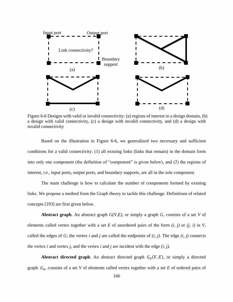
166
Figure 6-6 Designs with valid or invalid connectivity: (a) regions of interest in a design domain, (b)
a design with valid connectivity, (c) a design with invalid connectivity, and (d) a design with
invalid connectivity
Based on the illustration in Figure 6-6, we generalized two necessary and sufficient
conditions for a valid connectivity: (1) all existing links (links that remain) in the domain form
into only one component (the definition of “component” is given below), and (2) the regions of
interest, i.e., input ports, output ports, and boundary supports, are all in the sole component.
The main challenge is how to calculate the number of components formed by existing
links. We propose a method from the Graph theory to tackle this challenge. Definitions of related
concepts [193] are first given below.
Abstract graph. An abstract graph G(V,E), or simply a graph G, consists of a set V of
elements called vertex together with a set E of unordered pairs of the form (i, j) or (j, i) in V,
called the edges of G; the vertex i and j are called the endpoints of (i, j). The edge (i, j) connects
the vertex i and vertex j, and the vertex i and j are incident with the edge (i, j).
Abstract directed graph. An abstract directed graph 𝐺𝑑(𝑉, 𝐸), or simply a directed
graph 𝐺𝑑, consists of a set V of elements called vertex together with a set E of ordered pairs of
Input port Output port
Boundary
support
Link connectivity?
(a) (b)
(c) (d)
167
the form (i, j), i and j in V, called the directed edges (or simply edges) of 𝐺𝑑;the vertex i is called
the initial vertex and vertex j the terminal vertex. Together they are called the endpoints of (i, j).
The only difference between a graph and a directed graph is that the edges of a directed
graph are ordered pairs of vertices while the edges of a graph are not. The edge (i, j) is directed
or oriented from node i to node j in Gd, and that (i, j) is incident with nodes i and j or
alternatively that (i, j) is directed away or outgoing from i and directed toward or terminating at j.
Component. A component of a graph or undirected graph is a connected sub-graph
containing the maximal number of edges.
In TO, a component can be understand as a connected structure where all the existing
vertices are connected one another through the existing links. For instance, for the design in
Figure 6-6b (and also the one in Figure 6-6d), there is only one component. But for the design in
Figure 6-6c, there are two components that are disconnected from each other.
Rank. The rank r of a graph or undirected graph with n vertices (or nodes) and c
components is defined as the number 𝑟 = 𝑛 − 𝑐.
Vertex-edge incidence matrix. The vertex-edge incidence matrix, denoted by 𝑉𝐸, of a
directed graph Gd is a 𝑛 × 𝑚 matrix such that if 𝑉𝐸 = [𝑉𝐸𝑖𝑗], then
(1) 𝑉𝐸𝑖𝑗 = 1, if edge 𝑒𝑗 is incident at vertex i and is directed away from node i,
(2) 𝑉𝐸𝑖𝑗 = −1, if edge 𝑒𝑗 is incident at vertex i and is directed toward node i,
(3) 𝑉𝐸𝑖𝑗 = 0, if edge 𝑒𝑗 is not incident at node i,
where n is number of vertices and m is number of edges in the directed graph.

168
Figure 6-7 Connectivity check for different designs based on their directed graphs: (a) a valid
design; (b) an invalid design; and (c) an invalid design. VE is the vetex-edge matrix; r is rank of VE;
n is number of existing nodes; c is the number of components
In TO, each mechanism design is an assembly of links that remain in the design domain,
(existing links). Apparently, the nodes of these existing links also exist in the design domain. The
existing links and existing nodes of a design is abstracted as a directed graph (existing links are
the edges and existing nodes are the vertices). In the directed graph, the directions of the edges
are randomly predetermined since the directions of the edges are not important in the study as
long as they are predetermined and fixed throughout the checking process. The vertex-edge
incidence matrix VE and the rank (r) of this matrix are first calculated. Then the number (n) of
the existing nodes is calculated. According to the definition of the rank of a directed graph, i.e.,
𝑟 = 𝑛 − 𝑐, the number (c) of components in the directed graph is
VE =
(a)
1 2
3
1 2
1 2
5 4
4
3
3
(c)
𝑒1 𝑒2
𝑒3 𝑒4
𝑒1 𝑒2
𝑒3
𝑒1 𝑒2
VE =
r = 3
n = 4
VE =
r = 3
n = 5
n = 3
r = 2
(b)

169
𝑐 = 𝑛 − 𝑟. (6.2)
Based on the two conditions for a valid connectivity, if c = 1 and all the regions of
interest are in the only component, the design has valid connectivity; otherwise, the design has
invalid connectivity. Figure 6-7 shows the connectivity check for the three design examples in
Figure 6-6. In Figure 6-7a, c equals one, and all the regions of interest are in the only component,
and thus the design is valid; in Figure 6-7b, c equals two, and thus the design is invalid; in Figure
6-7c, c equals one, but the boundary support is not among the existing nodes, and thus the design
is invalid.
6.2.4 Finite Element Analysis Using SPACAR
In this study, a program—SPACAR [194-196] that was originally developed at TU
Delft—was employed for the geometrically nonlinear finite element analysis of CMs. Three
special features of the finite element theory in SPACAR are (1) both links and joints can be
modeled as specific finite elements, i.e., beam elements and hinge elements, respectively; (2) the
rigid-body rotation and bending deformation of a beam element are explicitly and separately
defined; (3) the deformation of elements can be specified as input motion. This section briefs the
finite element approach in SPACAR by focusing on fundamental concepts, the planar beam
element, and the hinge element.
Fundamental concepts. A mechanism is divided into an assembly of finite elements.
The configuration of an element is described by a set of nodal coordinates and deformation
parameters. Nodal coordinates includes the Cartesian coordinates and orientation coordinates.
The Cartesian coordinates describe the position of an element in a global coordinate system, and
orientation coordinates describe the orientation of the ends of the element to its reference
position (initial position). A deformation parameter describes the relevant deformation of an

170
element and is defined as a function of the nodal coordinates of the element. The deformation
modes of all the elements of a mechanism are described as
𝜺 = 𝜺(𝒙), (6.3)
where 𝒙 and 𝜺 are the vector of nodal coordinates and the vector of deformation parameters of
all the elements, respectively. The nodal coordinates are classified into three groups:
𝒙(0), 𝒙(𝑚), 𝒙(𝑐); also, the deformation parameters are classified into three groups: 𝜺(0), 𝜺(𝑚), 𝜺(𝑐).
Definitions of these groups are listed in Table 6-1. Equation (6.3) can further be expressed as
[𝜺(0)
𝜺(𝑚)
𝜺(c)] = [
𝜺(0)(𝒙(0), 𝒙(m), 𝒙(c))
𝜺(𝑚)(𝒙(0), 𝒙(m), 𝒙(c))
𝜺(𝑐)(𝒙(0), 𝒙(m), 𝒙(c))
]. (6.4)
Equation (6.4) defines the equations for kinematic analysis. The objective of kinematic
analysis is to solve the system of equations for vectors 𝒙(c) and 𝜺(c). Static analysis and
dynamic analysis are performed based on the principle of virtual power, given the
inertia/stiffness/damping properties [195, 196].
Table 6-1 Nodal coordinates and deformation parameters
Note that if the deformation of elements is the input motion of a mechanism, the input
can be specified through 𝜺(𝑚). This is one of the special features of the finite element approach in
SPACAR and was exploited to specify the bending motion of bending actuators and the rotary
motion of rotary actuators in this study.
Parameter Definition
𝑥(0) vector of coordinates specified as displacement boundary conditions
𝑥(𝑚) vector of coordinates specified as inputs
𝑥(𝑐) vector of dependent coordinates to be calculated
휀(0) vector of deformation parameters specified as zero, i.e., no deformation
휀(𝑚) vector of deformation parameters specified as inputs
휀(𝑐) vector of dependent deformation parameters to be calculated

171
Planar beam element. Figure 6-8a illustrates the definition of the beam element in
SPACAR. The beam element has two end nodes: node p and node q. Each end node has two
Cartesian coordinates and one orientation coordinate; the vector of the nodal coordinates of the
beam element is
𝒙 = [𝒙𝑝
𝒙𝑞] = [𝑥𝑝, 𝑦𝑝, ∅𝑝, 𝑥𝑞 , 𝑦𝑞 , ∅𝑞]𝑇, (6.5)
where (𝑥𝑝, 𝑦𝑝) and (𝑥𝑞 , 𝑦𝑞) are the Cartesian coordinates describing the positions of the element,
and ∅𝑝 and ∅𝑞 are the orientation coordinates describing the orientation of the nodes. The
orientation coordinate ∅𝑝 (∅𝑞) is the angle between the tangent of the beam’s deformed shape
at node p (q) and the reference or original orientation of the beam element; in other words,
∅𝑝 (∅𝑞) is defined with respect to the reference orientation of the element.
The changes of orientation coordinates are attributed to both the rigid-body rotation and
bending deformation of the element. The rigid-body rotation is captured by the dashed line—the
co-rotated line—between nodes p and q. (The co-rotated line rotates as the rigid-body rotation
changes.) The measure of the rigid-body rotation is (∅ − ∅𝑟), where ∅ and ∅𝑟 represent the
instantaneous and original orientations of the co-rotated line in the global x-y coordinate system,
respectively. Thus, ∅𝑝 − (∅ − ∅𝑟) represents the nodal orientation change (or nodal rotation) of
node p due to bending deformation, and ∅𝑞 − (∅ − ∅𝑟) represents the nodal orientation change
(or nodal rotation) of node q due to bending deformation. Other than the two bending
deformation modes, 휀2 and 휀3, the element also has an elongation deformation mode, 휀1,
describing the length change of the element. The measures for the three deformation modes are
given in Equation (6.6):
휀1 = ((𝑥𝑞 − 𝑥𝑝)2 + (𝑦𝑞 − 𝑦𝑝)2)1 2⁄ − 𝑙𝑟,
휀2 = sin(𝜃𝑝) ∙ 𝑙 = sin[(∅𝑝 − (∅ − ∅𝑟)] ∙ 𝑙,

172
휀3 = sin(𝜃𝑞) ∙ 𝑙 = −sin[∅𝑞 − (∅ − ∅𝑟)] ∙ 𝑙, (6.6)
where 𝑙 and 𝑙𝑟 are the instantaneous length and original length the element, respectively; ∅𝑝
(∅𝑞) is the angle between the tangent of the beam shape at node p (q) and the reference line; 𝜃𝑝
(𝜃𝑞) is the orientation change (or nodal rotation) of node p (q) due to bending deformation of the
element, and ∅ describes the orientation of the element: tan(∅) = 𝑦𝑞−𝑦𝑝
𝑥𝑞−𝑥𝑝 . For node p, 𝜃𝑝 =
∅𝑝 − (∅ − ∅r); similarly, for node q, 𝜃𝑞 = −[∅𝑞 − (∅ − ∅𝑟)]. 𝜃𝑝 and 𝜃𝑞 describes the shape of
the element. The shape function for the beam element is a cubic function.
With the definition of the beam element, we now further explain the objective function
introduced in Section 6.2.2. The target flexible link is modeled by one beam element. According
to the Equations (6.5) and (6.6), the configuration of a beam element can be described by six
coordinates. However, in this study, since the elongation of a beam element is very small
(otherwise yield failure) and its influence on the kinematics of the beam element is ignorable,
only five parameters are required to describe the configuration of the beam element (the target
flexible link), including the translational coordinates (𝑥𝑝, 𝑦𝑝) of a end node, the orientation ∅ of
the element, and the angle change 𝜃𝑝 and 𝜃𝑞 at the two end node.
Planar hinge element. The planar hinge element, with its axis perpendicular to the plane
of described motion, describes the relative rotation between two connected beam elements, as
shown in Figure 6-8b. The planar hinge element has two orientation nodes (p and q), and each
node has one orientation coordinate. The vector of the nodal coordinates of the hinge element is
𝒙 = [∅𝑝, ∅𝑞]T, (6.7)
where ∅𝑝 (∅𝑞) is the orientation coordinate of node p (q). When a hinge element is connected
to a beam element, the two elements share the same orientation node and orientation coordinate

173
at the connecting orientation node. The hinge element has only one deformation mode (the
relative rotation angle),
휀1 = ∅𝑞 − ∅𝑝. (6.8)
where 휀1 also represents the relative angle change between two connected beam elements.
Figure 6-8 (a) the coordinates and deformation parameters of the beam element and (b) the hinge
element between two connected beam elements
6.2.5 Parameterization
Parameterization defines the design variables that represent the physical systems to be
designed. In this study, three different systems were concerned: (1) a CM, (2) a CM actuated by
an optimally located bending actuator, and (3) a CM actuated by an optimally located rotary
motor.
Parameterization for CM design. In this case, the structure of a CM is the only design
goal. A design domain is discretized into a network of passive slender links whose
in-plane-widths (𝑊𝑖) are the design variables. Each design variable, representing the state of the
associated link in the domain (removed, or kept, and the in-plane-width if kept), has an integer
value from 0 to 5. “𝑊𝑖 = 0” means that the link is removed from the domain. Other values
represent the in-plane-width (unit: mm) of the link. For example, “𝑊𝑖 = 1” indicates that the link
(b) (a)
∅𝑝
Deformed beam element B
Original orientation
of beam element A
∅𝑞 Original orientation
of beam element B
Deformed beam element A
Hinge element

174
remains in the domain with an in-plane-width of 1 mm. Figure 6-9 depicts a design domain
which are discretized into 60 links with 16 blue dots. A line between two blue dots represents a
link. The specifications of a design problem include the length, width, out-of-plane thickness of
the design domain; boundary supports; the location, direction, and magnitude of actuation;
material; and the required configurations for the target link. Each link should be modeled by at
least one beam element for the analysis of CMs. In this study, without the loss of generality, each
link was modeled using only one beam element. Increasing the number of beam elements for
each link may (1) improve the power and accuracy of analysis and (2) allow more complex
shapes of the target link to be described but (3) increase computational costs.
Figure 6-9 Design domain for CMs of motion generation
Parameterization for CMs and bending actuators. In this case, both the structure of a
CM and the location of its bending actuator are the design goals. Based on the parameterization
scheme in the first case, two extra discrete design variables are added for the bending actuator.
The first variable has an integer value from 1 to n, where n is the number of links that discretize
the design domain. Its value marks the beam element selected to be active, i.e., the bending
actuator. The second variable equals to 2 or 3, and it represents the active bending deformation
mode of the active beam element. A beam element has two bending deformation modes, 휀2 and
Link A
Input motion
Link B

175
휀3, as illustrated in Equation (6.6). For instance, two extra variables need to be added to define a
bending actuator in the design domain illustrated in Figure 6-9. The first variable has an integer
value from 1 to 60, and the second variable has an integer value from 2 to 3.
Parameterization for CM and rotary actuator. In this case, both the structure of a CM
and the location of its rotary actuator are the design goals. Based on the parameterization scheme
of the first case, two extra design variables are added to define the location of the rotary actuator.
The rotary actuator connects two links and can actively change the relative angle between the
two links. Thus, the two links indicate the location of the rotary actuator in the design domain.
More precisely, the rotary actuator connects one end of each of the two links—“end1” and
“end2”, and the two ends are determined by the two extra design variables. Detailed steps on the
specification of the two design variables are given below:
(1) Number the ends of all links in order. Each link has two ends, and thus the total number of
ends is 2 times n, where n is the total number of links. In Figure 6-10, there are 60 links and
thus 120 ends.
(2) Among all the ends, select one end as “end1” based on the first discrete design variable “a”.
“a” has an integer value from 1 to 2n. In Figure 6-10, if “a” is 62, the B end of the link 31
(red line) is “end1”.
Note: Once “end1”is selected, “end2” can only be those ends that are connected at
the same location as “end1”. In Figure 6-10, since the B end of the link 31 is
selected as “end1”, “end2”can only be the other three ends that are connected at
the same location as “end1”.
(3) Among all the ends that are connected at the same location as “end1”, select one end as
“end2” based on the second discrete design variable “b”.
Note: We use ncs to denote the number of all the ends (except “end1”) that
connect at the same location as “end1”. Depending on where “end1” locates, ncs
may be different. For instance, if “end1” is the A end of link 31, ncs equals 7; if

176
“end1” is the B end of link 31, ncs equals 3. In the design domain in Figure 6-10,
ncs may have the value of 2, 3, 4, or 7, depending on where “end1” locates; thus,
“b” has an integer value from 1 to 84. 84 is the least common multiple of all the
possible values of ncs, i.e., 2, 3, 4, and 7. We determine the location of “end2”
through the discrete variable “b”. For example, if “enda” and “endb” are the only
two other ends at the same connection point with “end1” (ncs equals 2), when b is
in the range of 1~42, “enda” is selected as “end2”; when “b” is in the range of
43~84, “endb” is selected as “end2”. Similarly, if three other ends (ncs equals
3)—“enda”, “endb”, and “endc”—are at the same connection point with “end1”,
when “b” is in the range of 1~28, “enda” is selected as “end2”; when “b” is in the
range of 29~56, “endb” is selected as “end2”; when “b” is in the range of 57~84,
the “endc” is selected as “end2”. In this way, “end2” of the rotary motor can be
determined using the discrete variable “b”. This parameterization scheme may be
called as “roulette parameterization” since it has the same idea with a roulette.
For the case in Figure 6-10, the value of discrete variables “a” and “b” are 62 and 5 (5 is
in the range of 1~28).
Figure 6-10 Determining the location of the rotary actuator. The red line and blue line indicate the
two links connected by the rotary actuator
6.3 Design Examples
Three synthesis examples are presented to demonstrate the methodology described above.
The first example is to design CMs for motion generation, i.e., the structure of the CM is the only
design goal. For the first example, two design tests were conducted, and a compliant finger was
designed and manufactured. The second example aims to simultaneously determine the structure
of the CM and the location of its bending actuator while the third example determines the
structure of the CM and the location of its rotary actuator.
B
31
A

177
6.3.1 Motion-Generating Compliant Mechanism Design
Using the design domain shown in Figure 6-9, the first design test (T1) aims to design a
CM so that the target link is to be guided to a desired position, orientation, and shape. Different
from the first test, the second test (T2) has requirements only on the shape, i.e., bending
deformations, of the target link. The length, width, and out-of-plane thickness of the design
domain are 400 mm, 150 mm, and 10 mm, respectively. The maximum input motion is 5.6 mm,
and the material is polypropylene.
The desired configuration for T1 is defined in terms of five parameters: ∆x, ∆y, ∆∅,
∆𝜃𝑝 , and ∆𝜃𝑞 , whose values are 10.00 mm, −10.00 mm, 10.00°, −10.00°, and 10.00°
respectively, with the weighting factors of these terms all equal 1. The weighting factors were
determined by experimentally run the program to know the approximate average values of the
five terms. For T2, there are only requirements on ∆𝜃𝑝 and ∆𝜃𝑞 (i.e., 𝑤1 = 𝑤2 = 𝑤3 = 0, and
𝑤4 = 𝑤5 = 1): −10.00° and 10.00°.
Figure 6-11 shows the design results and their deformed configurations for T1 and T2,
respectively. The motion generation parameters of the results are listed in Table 6-2. As can be
seen, the target links in the results of the two tests have similar configurations. The values of the
objective functions for T1 and T2 are 4.36 and 0.04, respectively. In T2, the generated shape is
closer to the desired shape. This is because the shape change is the only concern, which provides
a more precise control over the deformed shape of the target link.
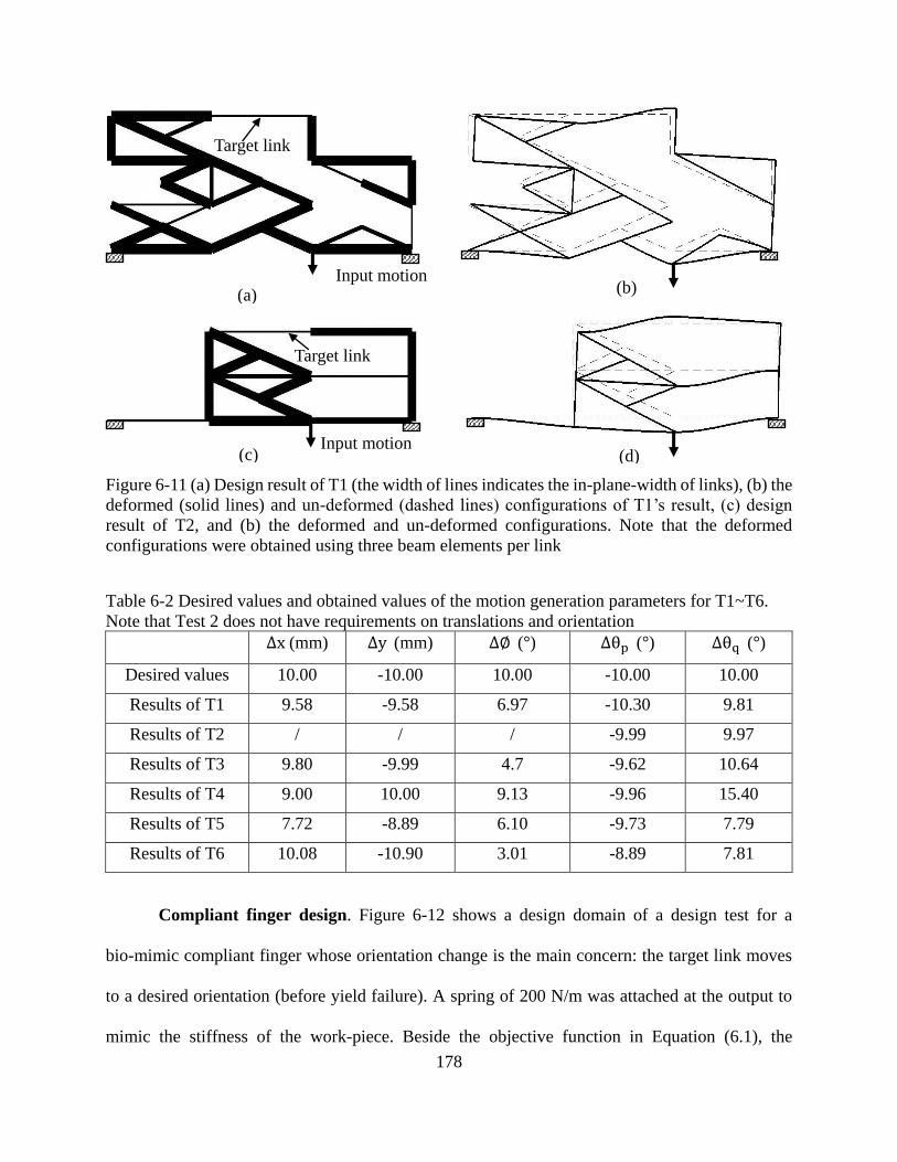
178
Figure 6-11 (a) Design result of T1 (the width of lines indicates the in-plane-width of links), (b) the
deformed (solid lines) and un-deformed (dashed lines) configurations of T1’s result, (c) design
result of T2, and (b) the deformed and un-deformed configurations. Note that the deformed
configurations were obtained using three beam elements per link
Table 6-2 Desired values and obtained values of the motion generation parameters for T1~T6.
Note that Test 2 does not have requirements on translations and orientation
∆x (mm) ∆y (mm) ∆∅ (°) ∆θp (°) ∆θq (°)
Desired values 10.00 -10.00 10.00 -10.00 10.00
Results of T1 9.58 -9.58 6.97 -10.30 9.81
Results of T2 / / / -9.99 9.97
Results of T3 9.80 -9.99 4.7 -9.62 10.64
Results of T4 9.00 10.00 9.13 -9.96 15.40
Results of T5 7.72 -8.89 6.10 -9.73 7.79
Results of T6 10.08 -10.90 3.01 -8.89 7.81
Compliant finger design. Figure 6-12 shows a design domain of a design test for a
bio-mimic compliant finger whose orientation change is the main concern: the target link moves
to a desired orientation (before yield failure). A spring of 200 N/m was attached at the output to
mimic the stiffness of the work-piece. Beside the objective function in Equation (6.1), the
Target link
Input motion (a) (b)
Target link
Input motion (c) (d)

179
required input displacement was also minimized. Figure 6-13 shows the design results. It is
shown that the deformed configurations from both the SPACAR simulation and the hand
manipulation over the prototype match to each other.
Figure 6-12 Design domain for bio-mimic compliant finger design and the desired orientation of
the target link. The height, width, and out-of-plane thickness of the design domain are 100 mm, 38
mm, and 5 mm, respectively.
Figure 6-13 Design results: (a) the link connectivity of the design; (b) the deformed and
un-deformed configurations analyzed using SPACAR (three beam elements per link); a truss
element (the blue line) is attached at the tip of the finger in the design process to ensure the
obtained design are stiff enough to transfer force; (c) the prototype made with polypropylene
through laser cutting; (d) the deformed prototype when actuated
60°
Target link
(b) (a) (c) (d)
Input motion

180
6.3.2 Integrated Design of Compliant Mechanisms and Bending Actuators
In this case, both the structure of a CM and the location of its bending actuator are the
design goals. Two design tests were performed (T3 and T4). Design specifications for both tests
are the same as those in T1 in Section 6.3.1 except the input motion. The direction and location
of the input motion is not specified in the two tests. The desired configurations for the target link
are 10.00 mm, -10.00 mm, 10.00°, −10.00°, and 10.00° for ∆x, ∆y, ∆∅, ∆𝜃𝑝, and ∆𝜃𝑞 ,
respectively.
Design results are shown in Figure 6-14. The objective values of the two tests are 6.62,
and 7.31, respectively. Table 6-2 shows the values of the motion parameters of the two tests. It is
seen that the two designs are both actuated by bending actuators at different locations. The
deformed shapes of the target link in the two designs are both close to the desired configuration
with some errors, which means the approach is able to generate designs which can approximately
fulfill the desired configuration. Size optimization may be applied for improvements. In addition,
it is noticed that the shape change of the target link is significantly larger than that in the bending
actuator—the bending deformation of the actuator is amplified. Thus, the approach may be
applied for the design of compliant amplifiers for bending actuators.

181
Figure 6-14 (a) design result of T3; (b) the deformed and un-deformed configurations of T3’s
result, and the green line indicates that the actuation of the CM is the third deformation mode of the
link; (c) design result of T4; (d) the deformed and un-deformed configurations of T4’s result, and
the blue line indicates that the actuation of the CM is the second deformation mode of the link.
6.3.3 Integrated Design of Compliant Mechanisms and Rotary Actuator
In this case, both the structure of a CM and the location of the rotary actuator (or motor)
are the design goals. Two tests (T5 and T6) were performed for the same objective as above.
Design results are shown in Figure 6-15. The objective function value of the three tests are 10.90
and 11.32, respectively. Table 6-2 shows the design parameters of the two tests. It is seen that the
three designs are all actuated by rotary actuators at different locations. The relative angle
between links connected by the rotary actuator changes. In addition, the two designs are both
close to the desired configuration with some errors, which means the approach is able to generate
designs which can approximately fulfill the desired configuration. To improve designs, size
optimization may be applied.
(a) (b)
Target link
Bending actuator
Target link
Bending actuator
(c) (d)

182
Figure 6-15 (a) design result of T5; (b) the deformed and un-deformed configurations of T5’s
result; (c) design result of T6; (d) the deformed and un-deformed configurations of T6’s result; The
two red lines in each result represent the two pin-connected links that the rotary motor drives
6.4 Conclusions
This paper presented a novel TO approach for the design of compliant robots (including
CMs and actuators) for motion generation. Motion generation was formulated in terms of the
position, orientation, and shape of a flexible link in the CM. Bending actuators and rotary motors
were incorporated as active components in the robot. The input motion of a bending actuator and
that of a rotary motor were modeled through the bending deformation of the beam element and
hinge element, respectively, in the finite element approach developed at TU Delft (the
Netherlands in the early 1970s). Novel parameterization schemes were developed for the optimal
placements of actuators. Based on the concept of directed graph theory, a new approach was
developed to check whether a design has valid connectivity among regions of interest. The three
design examples demonstrated that the proposed approach was able to simultaneously determine
(a) (b)
Target link
Rotary motor
(c)
Target link
(d)
Rotary motor
183
the structure of the CM and the optimal location of the actuator either a bending actuator or a
rotary motor, to guide a flexible link into desired configurations. The proposed approach has
potential applications in adaptive compliant systems where the properties of the systems must
actively change with respect to their environments. A future direction of research is to consider
more actuators in a CM.
Acknowledgements
The authors acknowledge a partial financial support to this research from the NSERC
Discovery Grant and the China Scholarship Council. We also thank Dr. Jaap Meijaard from the
University of Twente for his help with SPACAR. We acknowledge P.Eng Rick Retzlaff for
helping fabricate the compliant finger prototype.

184
CHAPTER 7
TOWARDS A UNIFIED DESIGN APPROACH FOR BOTH COMPLIANT MECHANISMS
AND RIGID-BODY MECHANISMS: MODULE OPTIMIZATION
Chapter 7 presents the study for Objective 5. CMs are designed by considering joints in
mechanisms. Specifically, Chapter 7 proposes analysis models and synthesis approaches which
are appropriate for both RBMs and CMs. The concept of a modularized mechanism is proposed
to generally represent RBMs and CMs. Compliant link (CL), rigid rink (RL), pin joint (PJ),
compliant joint (PJ), and rigid joint (RJ) are the five basic modules. Finite element models of
modularized mechanisms were developed based on a new beam-hinge model. Based on the
concept of modularized mechanisms and the beam-hinge model, a link and joint determination
approach, module optimization, was developed for the type and dimension synthesis of RBMs
and CMs together.
The work presented in this chapter is included in the following manuscript:
Cao, L., Dolovich, A., Schwab, A. L., Herder, J. L., and Zhang, W. J., 2014, “Towards a
Unified Design Approach for both Compliant Mechanisms and Rigid-Body Mechanisms:
Module Optimization”, ASME Journal of Mechanical Design, submitted as Research Paper,
under review, manuscript ID: MD-14-1782.
Abstract
RBMs and CMs have traditionally been viewed and treated in significantly different ways.
In this paper, we present an analysis approach and a synthesis approach that are appropriate for
both RBMs and CMs. RBMs and CMs were generalized into modularized mechanisms that
consist of five basic modules: compliant links, rigid links, pin joints, compliant joints, and rigid
joints. The finite element model of modularized mechanisms based on a new beam-hinge model

185
was developed to represent the five modules and to specify rotational input motion. A link and
joint determination approach—module optimization—was then developed for the type and
dimensional synthesis of both RBMs and CMs. In the module optimization approach, the states
(existence and sizes) of joints and links were all design variables, and one may obtain a RBM, a
partially CM, or a fully CM for a given mechanical task. Three design examples of path
generators demonstrated the effectiveness of the proposed approach to the type and dimensional
synthesis of RBMs and CMs.
7.1 Introduction
Two major categories of mechanisms are RBMs and CMs. A RBM gains all its motion
from the relative movements between its rigid members through kinematic pairs or joints. In
contrast, a CM gains at least part of its motion from the deformation of its deformable members
[2]. This difference makes RBMs and CMs quite different in analysis and synthesis. However,
RBMs can be practically viewed as a CM because there is no absolutely rigid component. Along
this line of thinking, a new approach to mechanism synthesis called module optimization is
presented in this paper. The idea is to not distinguish between RBMs and CMs, and a component
in a mechanism is thus called a module. Further, with this approach, there is no separation of
type synthesis and dimensional synthesis (the two design activities are separated in traditional
mechanism design theory).
Type synthesis involves determining a proper mechanism topology to best suit a desired
mechanical task [197]. The “topology” here includes the number of links and joints, the types of
the joints, the connectivity of the links and the joints, the types and locations of inputs, and the
displacement boundaries (ground) [33, 34]. Dimensional synthesis involves determining the
geometry of a mechanism to accomplish a specified task [2]. Approaches to type synthesis (i.e.,

186
no dimension information is considered) and approaches to concurrent synthesis of both type and
dimension can be found in the literature for both RBMs and CMs [38, 40, 61, 97, 115, 198-203].
A typical approach to the type synthesis of RBMs is to enumerate the basic kinematic
chains based on a matrix representation of mechanism topology and to perform analysis based on
graph theory [33, 204, 205]. The number and the connectivity of links and joints are to be
determined. This approach has also been extended for the type synthesis of CMs [55]. It is clear
that type synthesis only accomplishes a partial task.
Two approaches exist for the concurrent type and dimensional synthesis of RBMs. One is
based on a truss ground structure model [199, 200, 202], and the other is based on a
spring-connected rigid block model [203]. In the first approach, a network of rigid truss links are
used to initialize in a design domain. By removing some links in the design domain based on an
iterative optimization and analysis scheme, the remaining truss links form a RBM and thus
provide the topology and dimension of the mechanism in design. This approach can be called a
link determination approach, as the final topology of a RBM is determined by the remaining
links in the design domain. In the second approach, rigid blocks, in a design domain, are
connected through the zero-length springs. By keeping or removing some of these springs, the
connectivity among the rigid blocks can be determined: disconnected, rigidly connected, or
connected through pin joints. Note that blocks or links are not removed in this approach, and the
topology of a mechanism is only determined by the remaining springs (joints). The approach can
thus be called a joint determination approach.
Ananthasuresh [38] pioneered the type and dimensional synthesis of CMs based on TO
that was originally used for stiff structures. TO was then further developed based on a truss
(truss-only) ground structure model [40] and a beam (beam-only) ground structure model [61,

187
97]. Ramrakhyani et al. [115] developed a type of hinged-beam element that has a pin joint at
one end and a rigid joint on the other end. Similar to the truss ground structure approach for
RBM synthesis, approaches for the synthesis of CMs based on the truss-only, beam-only, and
hinged-beam ground structure models can be viewed as a link determination approach because
the final design is determined by the remaining links in the design domain.
The purpose of this study was to extend TO techniques to an integrated link and joint
determination approach called module optimization for the type and dimensional synthesis of
both RBMs and CMs. RBMs and CMs were modularized into a general mechanism that is
comprised of link modules and joint modules, including compliant links (CLs), rigid links (RLs),
pin joints (PJs), compliant joints (CJs), and rigid joints (RJs). The assembly of these modules
forms the topology and dimension of a mechanism. A new beam-hinge model was proposed
based on the planar beam element and hinge element in SPACAR (a finite element program
originally developed at TU Delft [196]) to represent link modules (beam elements) and joints
modules (hinge elements). A design domain is initialized with both beam elements and hinge
elements. By determining the state (PJ, CJ, or RJ) of each hinge element and that (absent, CL of
different sizes, or RL) of each beam element, a mechanism can be obtained. The proposed
approach for the synthesis of mechanisms has the following special features:
(1) The approach is used for the concurrent type and dimensional synthesis of RBMs, partially
CMs, and fully CMs. One may obtain a RBM, a partially CM, or a fully CM using this
approach.
(2) Designers are able to select their desired category of mechanisms prior to the design
process by prescribing the appropriate basic modules to be included in the design process.

188
For example, if a RBM is desired, one may exclude the CL and CJ modules and prescribe
RL, RJ, and PJ as basic modules to initialize design domains.
(3) The approach provides a new perspective on the relationship between RBMs and CMs:
their designs can be unified, which is philosophically correct because the rigid body is just
an assumption on the bodies with ignorable deformations.
(4) The approach is a combined link and joint determination approach. The states of links and
those of joints are all design variables, while the joint determination approach and link
determination approach predetermine the states of links and those of joints, respectively.
(5) Rotational input motion can be specified in a natural way due to the advantage of the
proposed beam-hinge model (refer to Section 7.3.3 for details). This feature facilitates the
synthesis of mechanisms (especially CMs) for more complicated motion tasks that are
defined by rotational motion. In the literature, CMs are mainly designed through TO for
simple tasks such as amplifying motion or gripping [48], and the type of motion is mainly
translational motion.
(6) CJs are incorporated into the type and dimensional synthesis of CMs. CJs have long been
considered in the architecture of CMs [4, 5, 7, 9, 206] but have never been considered in the
type and dimensional synthesis of CMs.
7.2 Modularization of Rigid-Body Mechanisms and Compliant Mechanisms
Figure 7-1a shows a four-bar RBM whose links are rigid and connected by PJs. By
replacing the PJs with CJs, e.g., notch-type CJs, one can obtain a lumped four-bar CM, as shown
in Figure 7-1b. The links in the lumped CM are relatively rigid but are connected by the
notch-type compliant joints that permit relative rotation (through deformation) between the
connected links. Instead of using CJs, a distributed four-bar CM, as shown in Figure 7-1c,

189
consists of CLs that connect through RJs. RJs do not permit relative rotation between the
connected links, but the links are flexible and can be deformed throughout the bodies. Figure
7-1d is a partially compliant mechanism where the motion is from the deformation of its
compliant components and the relative rotation of the links permitted by the PJs. With these
observations, these mechanisms can be generally viewed as an assembly of link modules and
joint modules, as shown in Figure 7-1e. Link modules consist of RL and CL modules, and joint
modules consist of PJ, CJ, and RJ modules. In general, as shown in Figure 7-1f, any type of
mechanisms can be modularized as an assembly of link modules and joint modules. The type of
a mechanism is determined by the types of modules and how the modules are connected.
Figure 7-1 Modularization of four-bar mechanisms: (a) a four-bar rigid-body mechanism, (b) a
four-bar lumped fully CM, (c) a four-bar distributed fully CM, (d) a four-bar partially CM, (e) a
modularized four-bar mechanism with link and joint modules, and (f) a general modularized
mechanism with link and joint modules (the dotted lines represent any possible connectivity)
(e)
?
Rigid joint
Compliant joint
Pin joint
Rigid link
Compliant link
Legend
?
(f)
Rigid link Pin joint
Flexure hinge
Rigid joint
Compliant link
(a) (b) (c)
(d)
?
?
?
?
?
? ?
? ?
?
?
?
?
?
?
?

190
7.3 Finite Element Modeling
This section introduces the finite element program, SPACAR [195, 196], to model
modularized mechanisms. One special characteristic of this finite element theory is that both
links and joints can be modeled using specific finite elements, i.e., the beam element and the
hinge elements, respectively. Fundamental concepts, such as the beam element and hinge
element, are briefly introduced here (refer to [194-196, 207] for details), followed by the finite
element representations of modularized mechanisms.
A mechanism is divided into an assembly of finite elements. The configuration of an
element is described by a set of nodal coordinates and deformation parameters. Nodal
coordinates include the Cartesian coordinates and orientation coordinates. The Cartesian
coordinates describe the position of an element in a global coordinate system, and the orientation
coordinates describe the orientation of an element to its reference position (usually the initial
position). A deformation parameter describes the relevant elastic deformation mode of an
element and is defined as a function of the nodal coordinates of the element. One important
principle for deformation modes is Principle I: the number of deformation modes of an element
equals the number of nodal coordinates minus the number of degrees of freedom of the element
as a rigid body [196]. All the deformation parameters of the elements of a mechanism are
described as
𝜺 = 𝜺(𝒙), (7.1)
where 𝒙 is the vector of the nodal coordinates of all the elements that represent the mechanism,
and 𝜺 is the vector of the deformation parameters. The nodal coordinates are classified into three
groups: 𝒙(0), 𝒙(𝑚), 𝒙(𝑐) ; also, the deformation parameters are classified into three groups:
𝜺(0), 𝜺(𝑚), 𝜺(𝑐). Definitions for these groups are listed in Table 7-1. With the specified parameters
𝒙(0), 𝒙(𝑚), 𝜺(0), and 𝜺(𝑚), Equation (7.1) is expressed as
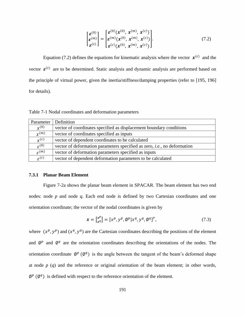
191
[𝜺(0)
𝜺(𝑚)
𝜺(c)] = [
𝜺(0)(𝒙(0), 𝒙(𝑚), 𝒙(𝑐))
𝜺(𝑚)(𝒙(0), 𝒙(𝑚), 𝒙(𝑐))
𝜺(𝑐)(𝒙(0), 𝒙(𝑚), 𝒙(𝑐))
]. (7.2)
Equation (7.2) defines the equations for kinematic analysis where the vector 𝒙(c) and the
vector 𝜺(c) are to be determined. Static analysis and dynamic analysis are performed based on
the principle of virtual power, given the inertia/stiffness/damping properties (refer to [195, 196]
for details).
Table 7-1 Nodal coordinates and deformation parameters
7.3.1 Planar Beam Element
Figure 7-2a shows the planar beam element in SPACAR. The beam element has two end
nodes: node p and node q. Each end node is defined by two Cartesian coordinates and one
orientation coordinate; the vector of the nodal coordinates is given by
𝒙 = [𝒙𝑝
𝒙𝑞] = [𝑥𝑝, 𝑦𝑝, ∅𝑝|𝑥𝑞 , 𝑦𝑞 , ∅𝑞]𝑇, (7.3)
where (𝑥𝑝, 𝑦𝑝) and (𝑥𝑞 , 𝑦𝑞) are the Cartesian coordinates describing the positions of the element
and ∅𝑝 and ∅𝑞 are the orientation coordinates describing the orientations of the nodes. The
orientation coordinate ∅𝑝 (∅𝑞) is the angle between the tangent of the beam’s deformed shape
at node p (q) and the reference or original orientation of the beam element; in other words,
∅𝑝 (∅𝑞) is defined with respect to the reference orientation of the element.
Parameter Definition
𝑥(0) vector of coordinates specified as displacement boundary conditions
𝑥(𝑚) vector of coordinates specified as inputs
𝑥(𝑐) vector of dependent coordinates to be calculated
휀(0) vector of deformation parameters specified as zero, i.e., no deformation
휀(𝑚) vector of deformation parameters specified as inputs
휀(𝑐) vector of dependent deformation parameters to be calculated

192
The change of orientation coordinates is attributed to both the rigid-body rotation and
material deformation of the element. The rigid-body rotation is indicated by the co-rotated line
(the dashed line) between nodes p and q. The rigid-body rotation equals (∅ − ∅𝑟), where ∅ and
∅𝑟 represent the instantaneous and original orientations of the co-rotated line, respectively. Thus,
∅𝑝 − (∅ − ∅𝑟) and ∅𝑞 − (∅ − ∅𝑟) represent the nodal orientation change of node p and that of
node q, respectively, due to the bending of the material. In addition to the two bending
deformation modes, 휀2 and 휀3, the element also has an elongation deformation mode, 휀1,
describing the length change of the element. The three deformation modes are calculated by
휀1 = ((𝑥𝑞 − 𝑥𝑝)2 + (𝑦𝑞 − 𝑦𝑝)2)1 2⁄ − 𝑙𝑟,
휀2 = sin[(∅𝑝 − (∅ − ∅𝑟)] ∙ 𝑙,
휀3 = −sin[∅𝑞 − (∅ − ∅𝑟)] ∙ 𝑙, (7.4)
where 𝑙 and 𝑙𝑟 are the instantaneous length and original length the element, respectively. The
deformation parameters in Equation (7.4) are invariant with respect to rigid-body movements of
the element [195].
7.3.2 Planar Hinge Element
The planar hinge element, with its axis perpendicular to the plane of described motion, is
developed to describe the relative rotation between two connected beam elements. The planar
hinge element has two orientation nodes (p and q), and each node has one orientation coordinate,
as shown in Figure 7-2b. The vector of the nodal coordinates of the element is
𝒙 = [∅𝑝, ∅𝑞]T, (7.5)
where ∅𝑝 (∅𝑞) is the orientation coordinate of the node p (q). The orientation coordinates are
defined with respect to the original orientations of the beam elements that are connected by the

193
hinge element. According to Principle I, the planar hinge element has only one deformation
mode:
휀1 = ∅𝑞 − ∅𝑝. (7.6)
where 휀1 represents the change of the relative angles between two connected beam elements.
Note that both the planar beam element and planar hinge element can be defined with relevant
stiffness properties.
Figure 7-2 (a) the coordinates and deformation parameters of the beam element and (b) the hinge
element between two connected beam elements
7.3.3 New Beam-Hinge Model and Conventional Beam-Only Model
With the beam element and hinge element, a new beam-hinge ground structure model is
proposed based on the beam element and hinge element introduced above. The new beam-hinge
model has two essential features compared with the beam-only model that is widely used in TO.
First, the joint stiffness between two connected beam elements can be described and controlled
through the hinge element, while the joint in the conventional beam-only model is simply
assumed rigid. Second, the relative angle between two connected beam elements can be
explicitly described and actively varied through either the orientation coordinate or the
deformation mode of the hinge element.
(b) (a)
∅𝑝
Deformed beam element B
Original orientation
of beam element A
∅𝑞 Original orientation
of beam element B
Deformed beam element A
Hinge element

194
The two features are demonstrated through an example. Figure 7-3a shows a
conventional beam-only model: two beam elements A and B are connected at the node 3 whose
coordinates are described through displacements (𝑢3, 𝑣3, 𝜃3). 𝑢3 and 𝑣3 indicate the position of
the node, and 𝜃3 indicates the orientation (or rotation) of the node. The two beam elements
share the same rotation coordinate at node 3, i.e., 𝜃3, which means that the relative angle
between A and B is fixed. In other words, A and B are rigidly connected. Figure 7-3b shows a
beam-hinge model: two beam elements A and B are connected at the translation node 3, and their
orientation nodes 4̃ and 5̃ are connected through a hinge element C (a circle filled with blue
color). The two beam elements have the same translation node but different orientation nodes.
The coordinates of 4̃ and 5̃ are ∅4 and ∅
5, respectively. ∅
4 and ∅
5 are measured with
reference to the original configuration of the structure, i.e., they equal zero in the original
configuration. The relative angle between A and B is thus ∅5 − ∅
4 which equals the
deformation 휀1 of the hinge element. One can specify the relative angle by specifying
either ∅4 and ∅5 , or 휀1 . Given the relative angle or deformation parameter, the moment
transferred between A and B is determined by the torsional stiffness of the hinge element C. In
other words, the hinge stiffness determines how strongly A and B are connected (in the torsional
direction).
Figure 7-3 Conventional beam-only model and the proposed beam-hinge model
Beam element A
Beam element B
Rigid joint 3 (𝑢3, 𝑣3, 𝜃3)
1
2
Beam element A
Beam element B
Hinge element C 1
2
3
(𝑥3 , 𝑦3) 5̃ (∅5)
4̃
(∅4 )
(a) (b)

195
7.3.4 Finite Element Representation
Based on the beam-hinge model, Figure 7-4a and Figure 7-4b show the finite element
representations of the modularized mechanisms in Figure 7-1e and Figure 7-1f, respectively.
Beam elements and hinge elements model the link modules and the joint modules, respectively.
The stiffness properties of the beam elements and hinge elements also indicates those of the
modules. For instance, a PJ is modeled as a hinge element of zero torsional stiffness while a CJ is
modeled as a hinge element with a specified positive torsional stiffness, and a RJ is modeled by a
hinge element with fairly large stiffness.
In the generalized modularized mechanism, multiple joints may exist at the same
connection point, so that multiple hinge elements are required to explicitly describe these joints.
Specifically, 𝑛 − 1 hinge elements are required to describe the connections between n beam
elements that are connected at the same location. One of the n beam elements is selected as the
intermediate beam element, and each of the other beam elements is connected to the intermediate
beam element through a hinge element. Each hinge element i shares one orientation node �̃�𝑖
with the intermediate beam element, and the other orientation node �̃�𝑖 of the hinge element is
shared with another beam element in that region. To aid understanding, a dashed circle is used to
indicate a multi-hinge region where multiple hinge elements exist at the same connecting
location (the center of the multi-hinge region). In one multi-hinge region, each beam element
(except the intermediate element) is adjacent to a hinge element that connects the beam element
to the intermediate beam element.

196
Figure 7-4 (a) FEM representation of the modularized four-bar mechanism and (b) FEM
representation of the general modularized mechanism
7.4 Module Optimization of Mechanisms
This section introduces the module optimization of mechanisms. Section 7.4.1 introduces
the design domain and design variables. The objective function and constraints are introduced in
Section 7.4.2 and Section 7.4.3, respectively.
7.4.1 Design Domain and Design Variables
Figure 7-5 shows a design domain where a group of points was selected to be connection
points, and the beam elements were connected through the hinge elements at these points. In a
multi-hinge region, each beam element (except the intermediate element) is adjacent to a hinge
element, which connects the beam element to the intermediate beam element. Refer to Section
7.3.4 for details.
Two strategies can be used to model a modularized mechanism in a given design domain:
an explicit model and an implicit model. The explicit model explicitly defines the state of a
module. Specifically, the removed (non-existing) links and joints are not modeled, and rigid links
and rigid joints are modeled with beam elements whose deformation modes are suppressed, i.e.,
휀 = 0. The implicit model, however, defines the state of a module in a way that the removed
links and joints are modeled with very small stiffness so that their effects on the mechanism
behaviors is negligible. Meanwhile, RLs (or RJs) are modeled with the beam elements (or hinge
Hinge element
Beam element
Multi-hinge
region
(a) (b)

197
elements), and all of their deformation modes are released, i.e., no constraint on 휀, but these
elements are assigned with relatively higher stiffness than those of CLs (or CJs). The first
strategy is straightforward, but the second strategy is more convenient to be implemented and
thus is used in this study.
Figure 7-5 Design domain based on the beam-hinge model
There are three groups of design variables. The first group is the continuous position
variables, (𝒙𝑝, 𝒚𝑝), of the connection points. Each connection point could locate at any
positions in a surrounding rectangular region, i.e., the floating region. One floating region of a
connection point is shown in Figure 7-5 as a sample. A floating region provides a connection
point with greater geometric freedom [113]. Note that these rectangular regions should not have
any intersection with one another. The second group of design variables is the discrete state
variables, 𝑳, of the links. Each link has three discrete states: removed from the domain,
remaining in the domain and compliant (remaining CL), and remaining in the domain and rigid
Hinge element
Beam element
Multi-hinge
region
Connection
point floating
region

198
(remaining RL). A remaining CL also has three levels of in-plane widths. A remaining RL is
assigned with a much larger bending stiffness and elongation stiffness compared with a present
CL. The state (and the in-plane width if it is a CL) of a link module 𝑖 is determined by 𝐿𝑖. Note
that a RL is only viewed as a piece of material with a relatively very large stiffness. The type of
the material and size (except the length) of a RL are not the concern in the present study and
should be considered in the embodiment design. The third group is the discrete state variables, 𝑱,
of the joints. Each joint has three states: PJ, CJ, and RJ.
7.4.2 Objective Function
The design problem in this study is to find the type and dimension of a mechanism (a
RBM or a CM) so that the mechanism follows a prescribed or desired path when actuated by a
rotational input motion. Thus, the functional requirement in this case is path generation, i.e., the
control of a point on a mechanism such that it follows a prescribed path [208]. Thus, the
objective function is to minimize the mean distance between the desired path and the generated
path:
Minimize mean distance =1
𝑛∑ 𝑑𝑖𝑛𝑖=1 , (7.7)
where n is the number of selected precision points on the desired path, and 𝑑𝑖 is the distance
from a precision point i to the generated path of a mechanism candidate. The mean distance is
schematically shown in Figure 7-6. The general idea is to determine the mean distance from the
selected precision points on the desired path to the generated path.

199
Figure 7-6 Desired path and generated path
7.4.3 Constraints
The purpose of the module optimization in the present study was
to find: 𝒙𝑝, 𝒚𝑝, 𝑳, 𝑱
to minimize 1
𝑛∑ 𝑑𝑖𝑛𝑖=1 ,
subject to:
Valid connectivity check
𝒙𝑝𝑙𝑜𝑤𝑒𝑟 ≤ 𝒙𝑝 ≤ 𝒙𝑝
𝑢𝑝𝑝𝑒𝑟
𝒚𝑝𝑙𝑜𝑤𝑒𝑟 ≤ 𝒚𝑝 ≤ 𝒚𝑝
𝑢𝑝𝑝𝑒𝑟
1.5 < 𝜆𝑏𝑢𝑐𝑘𝑙𝑖𝑛𝑔
|𝜎𝑚𝑎𝑥 _𝐶𝐿| < [𝜎]
|휀max _𝐶𝐽| < [휀𝐶𝐽]
|휀max _𝑅𝐽| < [휀𝑅𝐽]
|𝜃max _𝑅𝐿| < [𝜃𝑅𝐿]. (7.8)
Some notes on Equation (7.8) are given below:
(1) Valid connectivity check was performed for each candidate design to secure the
connections between the input port, the output port, and the displacement boundaries of a
mechanism.
𝑑𝑖
𝑖
Generated Path
Desired Path
Distance line Precision Point

200
(2) 𝒙𝑝 and 𝒚𝑝 are the vectors of the horizontal coordinates and the vertical coordinates of the
connection points, respectively. 𝒙𝑝 ragnes from 𝒙𝑝𝑙𝑜𝑤𝑒𝑟 to 𝒙𝑝
𝑢𝑝𝑝𝑒𝑟, and 𝒚𝑝 ranges from
𝒚𝑝𝑙𝑜𝑤𝑒𝑟 and 𝒚𝑝
𝑢𝑝𝑝𝑒𝑟.
(3) 𝑳 and 𝑱 are the vectors of the state values of the links and the joints, respectively.
(4) 𝜆𝑏𝑢𝑐𝑘𝑙𝑖𝑛𝑔 is the critical buckling load multiplier which equals the critical buckling load
over the input force or torque. 𝜆𝑏𝑢𝑐𝑘𝑙𝑖𝑛𝑔 is constrained to be larger than 1.5. This
constraint is imposed to ensure that the applied input force or torque was not large enough
to buckle the mechanism (refer to [191] for details).
(5) |𝜎𝑚𝑎𝑥 _CL| and [𝜎] are the maximum stress (absolute value) of a mechanism on all CLs
and the yield strength of the material used, respectively. The stress is the normal stress due
to bending and axial loadings.
(6) |휀𝑚𝑎𝑥 _CJ| and [휀CJ] are the maximum deformation (absolute value) of CJs and the
deformation limit, respectively. A CJ can only rotate in a limited range, depending on the
structure of the CJ. For example, the Free-Flex® Pivot (a CJ) designed by Riverhawk
Company can travel up to 60o [209].
(7) |𝜃𝑚𝑎𝑥 _RL| and [𝜃RL] are the maximum angular rotation (absolute) of RLs due to bending
deformation and the limit. A RL has two bending modes: 휀2 and 휀3. The angular rotations
due to bending deformation are 𝜃2 = 휀2 𝑙⁄ and 𝜃3 = 휀3 𝑙⁄ , where 𝑙 is the instantaneous
length of the RL. In the study, each RL is implicitly modeled using a beam element of high
stiffness, but with deformation modes being released, i.e., free to be deformed. The beam
element is supposed to function as a RL by implicitly suppressing deformation. However,
RLs may be undesirably deformed due to inappropriate topologies or dimensions. This
constraint limits the undesirable deformation of RLs to negligible small deformation.

201
(8) |휀𝑚𝑎𝑥 _RJ| and [휀RJ] are the maximum deformation (absolute value) and the deformation
limit of RJs, respectively. This constraint limits the undesirable deformation of RJs to
negligible small deformation.
Note that the constraints on RLs and RJs and the strength constraint on CLs ensure that
the mobility of a mechanism mainly comes from the bending of CLs, the relative rotation
permitted by PJs, and the deformation of CJs.
The optimization problem was solved using the genetic algorithm in the Global
Optimization Toolbox in Matlab [173]. The toolbox can solve optimization problems that have
both continuous and discrete variables [133].
7.5 Design Examples
Three design examples are presented to demonstrate the effectiveness of the proposed
module optimization technique. The three examples aim to design a RBM, a fully CM, and a
partially CM, for the same path generation task with the selected modules.
Design specifications on design parameters, design variables, beam elements, and hinge
elements are introduced in Section 7.5.1, followed by a description of the three design examples
in Section 7.5.2.
7.5.1 Design Specifications
The space has an area of 400×400 mm2, with a grid of 3×3 nodes, creating 20 beam
elements and 31 hinge elements, as shown in Figure 7-7. Each block has an area of 200 ×
200 mm2, and the location of each connection point is allowed to vary in a floating region of
190 × 190 mm2 surrounding it.

202
Table 7-2 and Table 7-3 list the design parameters and design variables, respectively. The
state of each link module is represented by the in-plane width of its beam element in FEA, as
presented in Table 7-4.
The in-plane-width and the Young’s modulus of each absent link were 1 × 109 mm and
1 × 10⁻¹³ Pa, respectively, for two reasons: (1) the stiffness of an absent link must be small
enough to be negligible, and (2) no buckling failure on an absent link if its 𝐸𝐴 ≪ 𝐸𝐼, where E, A,
and I is the Young’s modulus, the cross-sectional area, and the moment of inertia, respectively.
𝐸𝐴 and 𝐸𝐼 represent the axial rigidity and the flexural rigidity (in the bending direction),
respectively. The torsional stiffness of the hinge elements for PJ, CJ, and RJ was 0, 0.006, and
2.460 (unit: N ∙ m/rad). The stiffness of the CJs was selected so that the flexural rigidity
properties of the CJs and the CLs were on the same level. The stiffness of the RJs and the
in-plane width of the RLs were selected so that their flexural rigidity was far larger than those of
the CJs and the CLs.
Figure 7-7 Design domain
Hinge element
Beam element
Multi-hinge
region
Connection
point floating
region
Desired Path
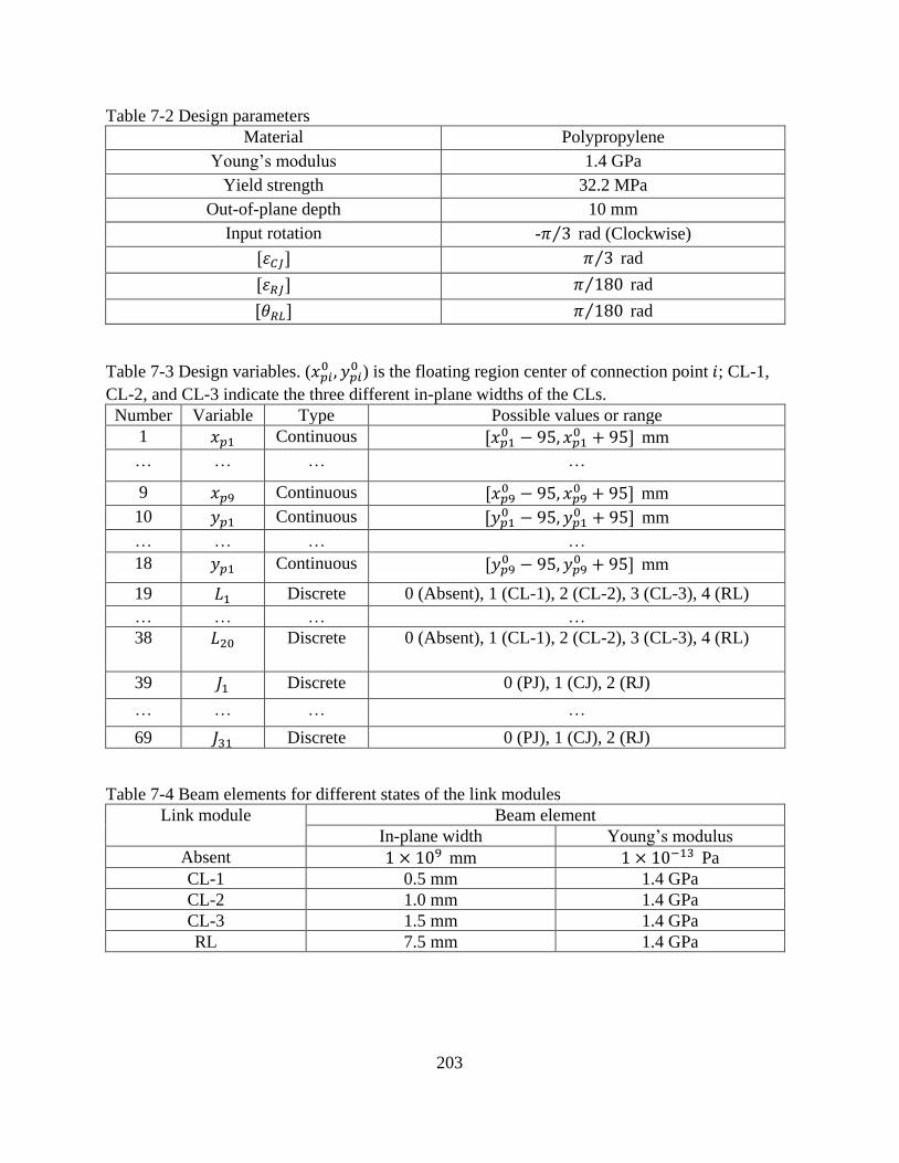
203
Table 7-2 Design parameters
Material Polypropylene
Young’s modulus 1.4 GPa
Yield strength 32.2 MPa
Out-of-plane depth 10 mm
Input rotation -𝜋 3⁄ rad (Clockwise)
[휀𝐶𝐽] 𝜋 3⁄ rad
[휀𝑅𝐽] 𝜋 180⁄ rad
[𝜃𝑅𝐿] 𝜋 180⁄ rad
Table 7-3 Design variables. (𝑥𝑝𝑖0 , 𝑦𝑝𝑖
0 ) is the floating region center of connection point 𝑖; CL-1,
CL-2, and CL-3 indicate the three different in-plane widths of the CLs.
Number Variable Type Possible values or range
1 𝑥𝑝1 Continuous [𝑥𝑝10 − 95, 𝑥𝑝1
0 + 95] mm
… … … …
9 𝑥𝑝9 Continuous [𝑥𝑝90 − 95, 𝑥𝑝9
0 + 95] mm
10 𝑦𝑝1 Continuous [𝑦𝑝10 − 95, 𝑦𝑝1
0 + 95] mm
… … … …
18 𝑦𝑝1 Continuous [𝑦𝑝90 − 95, 𝑦𝑝9
0 + 95] mm
19 𝐿1 Discrete 0 (Absent), 1 (CL-1), 2 (CL-2), 3 (CL-3), 4 (RL)
… … … …
38 𝐿20 Discrete 0 (Absent), 1 (CL-1), 2 (CL-2), 3 (CL-3), 4 (RL)
39 𝐽1 Discrete 0 (PJ), 1 (CJ), 2 (RJ)
… … … …
69 𝐽31 Discrete 0 (PJ), 1 (CJ), 2 (RJ)
Table 7-4 Beam elements for different states of the link modules
Link module Beam element
In-plane width Young’s modulus
Absent 1 × 109 mm 1 × 10⁻¹³ Pa
CL-1 0.5 mm 1.4 GPa
CL-2 1.0 mm 1.4 GPa
CL-3 1.5 mm 1.4 GPa
RL 7.5 mm 1.4 GPa

204
7.5.2 Design Illustrations
The three examples are to design a RBM, a fully CM, and a partially CM, respectively,
for the same path generation problem with selected modules. In the first example, RL, PJ, and RJ
modules are selected to be the basic modules in design; in the second example, except the PJ
module, all other modules are selected as basic modules, in the third example, all the five
modules are selected as basic modules. The desired path is defined as the curve of a quadratic
function:
𝑦 = −10(𝑥 − 𝑥𝑜𝑢𝑡𝑝𝑜𝑟𝑡)2+ 𝑦𝑜𝑢𝑡𝑝𝑜𝑟𝑡, 𝑥 ∈ [𝑥𝑜𝑢𝑡𝑝𝑜𝑟𝑡, 𝑥𝑜𝑢𝑡𝑝𝑜𝑟𝑡 + 0.12], (7.9)
where (𝑥, 𝑦) is the position coordinates of points on the curve, and (𝑥𝑜𝑢𝑡𝑝𝑜𝑟𝑡, 𝑦𝑜𝑢𝑡𝑝𝑜𝑟𝑡) is the
initial position coordinates of the output port of a mechanism. The curve was defined to make the
shape and size of the curve independent from the initial position (considered as design variables
in the study) of the output port of a mechanism. Note that the change in the x-coordinate from
the start to the end of the output path is 120 mm which is 30% of the characteristic length (400
mm) of the design domain.
7.6 Results and Discussion
7.6.1 Joint Conventions
To correctly interpret results, some conventions on joints must be described first. At each
connection point, 𝑛 − 1 hinge elements are used to describe the connections between n beam
elements that are connected at the same location. Specifically, one of the n beam elements is
selected as a intermediate beam element, and each of the other beam elements is connected to the
intermediate beam element through a hinge element. For example, as shown in Figure 7-8a, three
beam elements A, B, and C are connected at connection point 1. Element A is selected as the

205
intermediate beam element. The other two beam elements B and C are directly connected to A
through hinge elements d and e. Meanwhile, beam elements B and C are indirectly connected.
The interpretation of the joint connections of a design result is straightforward if the
intermediate link (intermediate beam element) remains in the design domain. Each joint
connection can be described by the relevant hinge element in a one-to-one manner: one hinge
element represents one joint module. However, this one-to-one manner of description is not
applicable when the intermediate link is absent (removed). For example, as shown in Figure 7-8b,
the intermediate beam A is absent, and link B and link C are present. The joints between link A
and link B and between link A and link C are a CJ and a RJ (Figure 7-8c), respectively. However,
the joint connection between link B and link C must be directly described by one joint module.
Thus, the combination of the CJ and RJ is interpreted as one CJ which connects link B and link C,
as shown in Figure 7-8d. Figure 7-9 shows the conventions.
Figure 7-8 Joint connection when the intermediate link is absent
A
B
C
4̃
2̃
3̃
(a) (b)
(c) (d)
A
B
C
A
B
C
B
C
d
e 1

206
Figure 7-9 Joint interpreting conventions. In each convention, the first term represents the joint
between a link B and an intermediate link A, and the second term represents the joint between the
other link C and the intermediate link A. The third term represents the joint between the link B and
link C. Joint interpreting conventions are used when the intermediate link is absent.
7.6.2 Results and Discussion
Design results using the genetic algorithm for Examples I ~ III are listed in Figure 7-10.
The first column shows both the absent links and the present links in the results, generated paths,
and desired paths. The in-plane widths of links are denoted by the widths of lines. The second
column shows both the link and joint modules in the design results. The first row to the third row
represent the design results for Examples I, II, and III, respectively. The values of the objective
functions of the three results are 0.0054, 0.0020, and 0.0017, respectively.
The result interpretation of Example I is depicted in Figure 7-11. The link and joint
modules of the original resulted mechanism (Figure 7-11a) is interpreted into the configuration
shown in Figure 7-11b according to the joint interpreting conventions. The interpreted
configuration consists of five RLs (besides the ground link), four PJs, and two RJs. The motion
of the mechanism is due to the relative rotation permitted by the PJs. Furthermore, the
mechanism in Figure 7-11b is equivalent to a rigid-body four-bar mechanism (Figure 7-11c)
because the clamped RL3 can be removed and the rigidly connected RL2 and RL1 can be viewed
as one RL. The kinematic degree of freedom of the mechanism was perfectly and correctly
limited to one due to the appropriate use of RJs and PJs, although five RLs (besides the ground
link) were used. Thus, it can be concluded that, on one hand, PJs provide a RBM with mobility;
+ =
+ =
+ =
+ =
+ =
+ =
Pin joint
Compliant joint
Rigid joint

207
Figure 7-10 Design results of Examples I~III
Legend

208
Figure 7-11 Result interpretation of Example I—Rigid-body path generator: (a) the joint and link
modules of the original result mechanism, (b) the interpreted joint and link modules of the
mechanism, and (c) the equivalent four-bar rigid-body mechanism
on the other hand, RJs and PJs together provide a RBM with the correct number of degrees of
freedom.
The first row and second row of Figure 7-12 depict the result interpretations of Examples
II and III, respectively. The first column, second column, and third column show the link and
joint modules of the original result mechanisms, those of the interpreted mechanisms (interpreted
according to the joint interpreting conventions), and the deformed configurations of the
interpreted mechanisms, respectively.
The interpreted fully compliant path generator of Example II (Figure 7-12b) consists of
five CLs, three CJs, and three RJs. No PJ appeared in the result. As seen from the deformed
configuration (Figure 7-12c), the CJs permit the relative rotation (deformation of CJs) between
the connected links and transmit bending moments. Both the rotational deformation of the CJs
and the bending deformation of the CLs contribute to the motion of the mechanism.
The interpreted partially compliant path generator of Example III (Figure 7-12e) consists
of eight CLs, two rigid links, six PJs, six CJs, and three RJs. All the five basic modules appeared
in the result. As seen from the deformed configuration (Figure 7-12f), the RLs and RJs do not
have any deformation, the PJs permit relative rotation between links without transmitting
(a) (b) (c)
RL3
RL1
RL2

209
moments, and the CJs permitted relative rotation with moment transmissions. All the modules
function as they were defined.
The implicit model (introduced in Section 7.4.1) used during the module optimization
process must be verified. Taking the design result of Example III for example, the generated path
based on the implicit model and the generated path based on the explicit model are almost the
same (as shown in Figure 7-13), which means that the implicit model used is accurate enough for
the proposed module optimization approach. Note that in the explicit model, each link of the
mechanism was discretized into three beam elements to ensure accuracy.
Figure 7-12 Interpretation of the results of Examples II~IV and the deformed configurations of the
CMs
(a) (c) (b)
(d) (f) (e)

210
Figure 7-13 Modeling of the result of Example III using the explicit model and the implicit model
7.7 Conclusions
A module view of mechanisms was proposed to generally represent RBMs and CMs,
using five basic modules: CLs, RLs, PJs, CJs, and RJs. The concept is general in the sense that
RBMs, fully CMs, and partially CMs can be all represented by these modules. Next, a finite
element model of both RBMs and CMs was established using a beam-hinge model that consists
of the beam element and the hinge element in a finite element approach developed at TU Delft
(Netherlands in early 1970). Subsequently, the concept of TO was borrowed to module
optimization, particularly to determine the “stay” or “leave” of modules that mesh a design
domain. The salient merits of introducing the hinge element include (1) a natural way to describe
various types of connections between two elements or modules and (2) a provision of the
possibility to specify rotational input motion in a design problem.
The module optimization approach covers both the so-called link determination approach
and the joint determination approach to the concurrent type and dimensional synthesis of
mechanisms in the literature. With the module optimization approach, one may obtain a RBM, a
211
partially CM, or a fully CM for a given mechanical task. The states of the joints and links do not
need to be predetermined, which allows more flexibility than both the joint determination
approach and the link determination approach. Furthermore, this approach also enables designers
to prescribe the types of modules prior to the design phase to obtain the desired categories of
mechanisms. Additionally, this work represents the first time that CJs are considered as the basic
modules in the type and dimensional synthesis of CMs, although many CJs for large rotation
have been designed and used in practice.
The proposed approach sets a foundation for the type and dimensional synthesis of RBMs
and CMs. With this foundation, one may design mechanisms for other functional requirements
such as function generation or motion generation.
In this study, a CJ was modeled using a hinge element that can only describe the
rotational stiffness of a CJ. The limitations of the model are listed below:
(1) The stiffness in translational directions was assumed to be infinite, i.e., a CJ is rigid in
translational directions (two beams connected by a CJ can only have relative rotation but
not relative translation). This approximation is reasonable when a CJ is designed with
lower rotational stiffness and higher translational stiffness. Some of these CJs can be
found in [4, 7, 9, 209].
(2) Although conventional notch type CJs can only travel over small limited ranges, the
angular travel of a CJ in this study was assumed to cover a large angle (60°) without yield
failure. Refer to [4, 7, 9, 209] for CJs with large travel angles.
(3) The size and physical construction of a CJ were not considered.

212
Another limitation of this study is that multiple joints may appear at the same connection
point (location). This limitation may require special treatments to locate these joints in
manufacturing; otherwise, the modeling is an approximation.
Acknowledgements
The authors acknowledge the partial financial support from the NSERC Discovery Grant
and the Chinese CSC. We also thank Prof. Jaap Meijaard from the University of Twente for
providing the advanced version of SPACAR and for his instructions on the use of SPACAR.
213
CHAPTER 8
CONCLUSIONS, CONTRIBUTIONS, AND FUTURE WORK
This dissertation set out to design (1) efficient and strong CMs and (2) CMs with the
insight on the joints, actuations, and functional requirements of mechanisms. Three frameworks
are proposed in this dissertation: (1) the design of efficient and strong CMs, (2) the integrated
design of CMs and rotary motors or bending actuators for motion generation, and (3) the module
optimization for RBMs and CMs.
8.1 Conclusions
The traditional stiffness-flexibility criterion results in lumped CMs that are efficient in
transferring motion, force, or energy but are prone to localized high stress and thus weak to resist
yield or fatigue failure. Researchers thus have attempted to design distributed CMs that generally
have better stress distribution than lumped CMs. However, distributed CMs generally are not as
efficient as their lumped counterparts. In this dissertation, a new TO framework is presented for
the systematic design of efficient and strong CMs based on the concept of hybrid CMs and an
input stroke design criterion. Hybrid CMs provide a way to integrate lumped compliance and
distributed compliance in a CM (i.e., hybrid CM). Meanwhile, the input stroke criterion, together
with the stiffness-flexibility criterion, leads to an effective way to integrate lumped compliance
and distributed compliance for efficient and strong CMs. In this work, a hybrid CM was assumed
as consisting of both circular flexure hinges and straight beams. A circular flexure hinge tends to
provide lumped compliance while a straight beam provides distributed compliance to the hybrid
CM. A new type of finite element for circular flexure hinges—super flexure hinge element—is
incorporated with classic beam elements to mesh or initialize a design domain. Thus, the design

214
results from such a design domain may have both flexure hinges and beams, i.e., hybrid CMs.
However, this does not necessarily lead to a proper integration of lumped compliance and
distributed compliance. In contrast, if only the stiffness-flexibility criterion is considered in the
optimization design model formulation, the design results may be extremely lumped with many
thin flexure hinges and thick beams, as can be seen from the results in Chapter 4. The reason is
that there is no preference for distributed compliance in the model. Thus, the input stroke
criterion was incorporated with the stiffness-flexibility criterion into the model formulation. The
input stroke of a CM, defined according to the von-Mises yield criteria, represents the maximum
allowable input displacement of the CM before yield failure. Indeed, a strong CM, ultimately, is
a CM that has large input motion range, i.e., large input stroke. With the formulation based on
the three criteria, i.e., stiffness, flexibility, and input stroke, and also the parameterization using
beam elements and super flexure hinge elements, strong and efficient CMs can be obtained, as
demonstrated by the design examples in Chapter 5. This result can also be explained through an
investigation on the effects of the location and size of a flexure hinge in a simple CM. The
investigation suggested that flexure hinges, if properly sized and located, may make a CM
efficient without leading to poor input stroke or poor compliance distribution. It is worthwhile to
point out that a more distributed CM does not guarantee a larger input stroke although it does in
many cases. The reason is that the compliance distribution of a CM is only dependent on how
materials are utilized to bear stresses or loads while the input stroke of a CM is dependent on not
only the stress distribution on the materials but also the input displacement per the cost of the
stress. Thus, when evaluating whether a CM is strong to resist yield failure, it is more precise and
practical to evaluate from the perspective of the input stroke rather than from the perspective of
the compliance distribution of the mechanism.

215
In traditional TO frameworks for CMs, except for the requirement on output
displacements, all the other procedures under these frameworks are basically the same as those
for structures. These frameworks naturally leads to the designed CMs much like the structures.
These CMs (1) do not have joints, (2) are actuated by a translational force, and (3) can only do
simple work such as amplifying motion or gripping. These features limit the applications of CMs.
In fact, CMs can have pin joints and compliant joints; also, many types of actuators can be used
to actuate a CM, e.g., rotary motors or bending actuators, and these CMs may be used for a
variety of different tasks. In the work of this dissertation, with the insight on the joints,
actuations, and functional requirements of mechanisms, two systematic design approaches were
developed to design CMs and they are concluded below.
First, a systematic design approach was developed for the integrated design of CMs and
actuators for motion generation. Both rotary actuators and bending actuators were considered.
The approach can simultaneously synthesize the optimal structural topology and actuator
placement for the desired position, orientation, and shape of a target link in the system, while
satisfying the constraints such as buckling constraint, yield stress constraint and valid
connectivity constraint. A geometrical nonlinear finite element analysis was performed for CMs
driven by a bending actuator and CMs driven by a rotary actuator. Novel parameterization
schemes were developed to represent the placements of both types of actuators. A new valid
connectivity scheme was also developed to check whether a design has valid connectivity among
regions of interest based on the concept of directed graph. Three design examples were
conducted and a compliant finger was designed and fabricated for the purpose of
proof-of-concept. The results demonstrated that the proposed approach is able to simultaneously
determine the structure of a CM and the optimal locations of actuators, either a bending actuator
216
or a rotary motor, to guide a flexible link into desired configurations. This approach has the
potential to be used for adaptive compliant systems, particularly for adaptive shape-morphing
compliant systems such as morphing airplane wings, whose behaviors or properties need to be
adapted or changed in response to the environment around them.
Second, with the concept of joints in mind, this study developed the analysis model and
synthesis approach that are appropriate for both RBMs and CMs. The concept of a module view
of mechanisms was proposed to represent RBMs and CMs in a general way particularly with five
basic modules—compliant link (CL), rigid rink (RL), pin joint (PJ), compliant joint (PJ), and
rigid joint (RJ). The concept is very general in the sense that RBMs, fully CMs, and partially
CMs were all readily represented by these modules. A beam-hinge model was proposed to
describe the connection among modules, in which a hinge element in the finite element approach
developed at TU Delft (Netherlands in early 1970) was borrowed. After that, a finite element
model of both RBMs and CMs was established. Then, the idea of TO was borrowed to module
optimization particularly with the essence of synthesis being to decide the “stay” or “leave” of
modules that mesh a design domain. The merits with the hinge element are (1) a natural way to
describe various types of connections between two elements or modules and (2) a provision of
the possibility to specify the rotational input and output motion as a design problem. The module
optimization approach covers both the so-called link determination approaches and joint
determination approaches to the concurrent type and dimensional synthesis of mechanism in the
literature. With the module optimization approach, one may obtain a RBM, or a partially CM, or
a fully CM for a given mechanical task. It is possible that designers can select different modules
prior to design to get desired categories of mechanisms. In addition, the states of joints and links
have no need to be predetermined, and thus this gives design more flexibility than the joint

217
determination approaches as well as link determination approaches. Also, this is the first time
that CJs are considered as basic modules in the type and dimensional synthesis although many
CJs for large rotation have been designed and used in practice. In short, the proposed module
optimization sets a foundation for the type and dimensional synthesis of RBMs and CMs. With
this foundation, one may design mechanisms with many other kinds of functional requirements,
such as for function generation, motion generation and so on.
8.2 Contributions
The main contributions of this dissertation to the field of CMs are highlighted below:
(1) Provision of a systematic framework for the design of strong and efficient hybrid CMs,
incorporating flexure hinges and the input stroke design criterion. The feature of this
framework is that it nicely integrates lumped compliance and distributed compliance for
the compromise or mutual benefits of the efficiency of transferring motion, force, or
energy and the capability of resisting failure of CMs.
(2) Provision of a super flexure hinge finite element. The element was verified and deemed
accurate and computationally efficient. This element can be used for the force-deflection
analysis and stress analysis of CMs with circular flexure hinges, with the consideration of
stress concentration in the flexure hinges.
(3) An input stroke metric that can be used to evaluate whether a CM is strong to resist yield
failure. The unique feature of this metric is that it indicates not only how materials are
utilized to bear stresses or loads but also the input displacement per the cost of the stress.
(4) Provision of a systematic framework for the integrated design of CMs and actuators for
motion generation. The framework has the following key features:
The use of bending actuator and rotary actuator as the actuation of CMs.

218
The simultaneous optimization of the location and orientation of the actuator concurrent
with the topology of CMs.
The implementation of guiding a flexible link through the initial and desired configurations,
including precision positions, orientations, and shapes.
(5) A beam-hinge analysis model and synthesis framework for both RBMs and CMs. The
analysis model can be used for the analysis of any rigid-body or compliant linkages. The
synthesis framework has the following specific merits:
The framework is for the concurrent type and dimensional synthesis of RBMs, partially
CMs, and fully CMs. One may obtain a RBM, or a partially CM, or a fully CM with this
approach.
Designers are able to select their desired category of mechanism prior to the design
process by prescribing appropriate basic modules to be included in the design process. For
example, if a RBM is desired, one may exclude the CL and CJ modules and prescribe RL,
RJ, and PJ as basic modules to mesh the design domain.
The framework provides a new perspective on the relationship between RBMs and CMs:
their designs can be unified, which is philosophically correct because the so called “rigid
body” is just an assumption on the body with negligible small deformation only.
The framework is a combined link and joint determination approach while each of the two
is available the in literature. The states of links and of joints are all design variables, while
both the joint determination approach and link determination approach predetermine the
states of links or joints, respectively.
The rotational input and output motion can be specified in a very natural way. This feature
is attributed to the advantage of the new beam-hinge model, where the relative angle

219
between any two connected beam elements can be explicitly described and actively varied.
With this advantage, one can design CMs for more complex motion tasks that are defined
by either rotational motion or translational motion or both.
CJs are incorporated into type and dimensional synthesis of CMs. Note that CJs have long
been considered in the architecture of CMs but they have never been considered in type
and dimensional synthesis of CMs. This means that the contemporary approach in the
literature to the synthesis of CMs is incomplete.
(6) Development of a new valid connectivity scheme to check whether a design has valid
connectivity among regions of interest based on the concept of directed graph.
8.3 Future Work
The future research directions are identified and discussed in terms of the three proposed
frameworks: (1) the design of efficient and strong CMs, (2) the integrated design of CMs and
actuators for motion generation, and (3) the module optimization for RBMs and CMs.
8.3.1 Design of Efficient and Strong Compliant Mechanisms
In this framework, although a spring is attached at the output port of the design domain to
model the resistance of the work-piece, the effects of the stiffness of the spring on design results
as well as the performance (efficiency and input stroke) of a CM are unknown. Furthermore, the
input force for CMs in the framework is also assumed constant. However, the output forces of
some widely used actuators, such as piezoelectric or electrostatic actuators, for CMs may vary
with displacements. This displacement-specific feature of actuators may alter the performance of
a CM. Therefore, further studies are required to investigate the effects of these issues and to
develop new design frameworks with these issues being considered.

220
In addition, this work integrated flexure hinges and beams for hybrid CM design by
taking advantage of their complementary inherent properties in stress distribution and energy
efficiency. In fact, flexure hinges have some other advantages compared with beams. For
instance, flexure hinges can better mimic pin joints and provide more accurate parallel
movement than beams. This feature of flexure hinges has been widely used for the design of
compliant parallel gripping mechanisms where the end-effectors must have parallel motion.
Hence, this feature may provide a novel direction to harness the advantages of such a beam
embedded with flexure hinges while mutually compensating their inherent limitations.
8.3.2 Integrated Design of Compliant Mechanisms and Actuators for Motion Generation
The benefit of considering actuators in the design phase of CMs is that the system may be
more adaptive in response to the environment changes. For instance, the performance of a CM is
highly sensitive to the loading at its output port; mostly, the mechanism has good performance
only for certain limited loading cases, and it cannot perform well once the loading changes. If
actuators are considered in the design phase, the system may be designed so that it is able to
adjust its properties to perform better in more loading cases by controlling the actuators.
However, the current framework only considers one actuator for a CM; it is worthwhile to have
more actuators in one CM, which would increase the capability of the system to adapt to external
loads and also increase the degrees of freedom of the system. Additionally, the framework may
be applied for the design of adaptive morphing wings for airplanes that can actively change
shapes to adapt to external varying loads.
8.3.3 Module Optimization for Rigid-Body Mechanisms and Compliant Mechanisms
Within the current framework of module optimization, only five passive modules are
considered, and the location, orientation, and type of input motion are specified prior to the
221
design phase. However, in essence, the “topology” of mechanisms includes the number of links
and joints, the types of joints, the connectivity of the links and joints, the input types and
locations, and the displacement boundaries (ground). From this perspective, the current module
optimization can be further developed to incorporate active modules such as translational
actuators, rotary actuators, and bending actuators in the design phase. This promising future
work will combine the second and third frameworks presented in this dissertation and result in a
more advanced module optimization approach.

222
LIST OF REFERENCES
[1] Je-Sung, K., Sun-Pill, J., Noh, M., Seung-Won, K., and Kyu-Jin, C., "Flea inspired catapult
mechanism with active energy storage and release for small scale jumping robot," Proc. Robotics
and Automation (ICRA), 2013 IEEE International Conference on, pp. 26-31.
[2] Howell, L. L., 2001, Compliant Mechanisms, John Wiley & Sons, New York.
[3] Kozuka, H., Arata, J., Okuda, K., Onaga, A., Ohno, M., Sano, A., and Fujimoto, H., 2013, "A
Compliant-Parallel Mechanism with Bio-Inspired Compliant Joints for High Precision Assembly
Robot," Procedia CIRP, 5(0), pp. 175-178.
[4] Kang, D., and Gweon, D., 2013, "Analysis and design of a cartwheel-type flexure hinge,"
Precision Engineering, 37(1), pp. 33-43.
[5] Hou, C.-W., and Lan, C.-C., 2013, "Functional joint mechanisms with constant-torque
outputs," Mech Mach Theory, 62(0), pp. 166-181.
[6] Luharuka, R., and Hesketh, P. J., 2012, "Compliant rotary mechanism and method," Google
Patents.
[7] Martin, J., and Robert, M., 2011, "Novel Flexible Pivot with Large Angular Range and Small
Center Shift to be Integrated into a Bio-Inspired Robotic Hand," J Intel Mat Syst Str, 22(13), pp.
1431-1437.
[8] Pavlović, N. T., and Pavlović, N. D., 2005, "Mobility of the compliant joints and compliant
mechanisms," Theoretical and Applied Mechanics, 32(4), pp. 341-357.
[9] Trease, B. P., Moon, Y.-M., and Kota, S., 2004, "Design of Large-Displacement Compliant
Joints," J Mech Design, 127(4), pp. 788-798.

223
[10] Krishnan, G., 2011, "An Intrinsic and Geometric Framework for the Synthesis and Analysis
of Distributed Compliant Mechanisms,"Ph.D., University of Michigan, Ann Arbor.
[11] Lu, K.-J., 2004, "Synthesis of shape morphing compliant mechanisms,"PhD, The University
of Michigan.
[12] Jutte, C. V., 2008, "Generalized synthesis methodology of nonlinear springs for prescribed
load-displacement functions,"PhD, University of Michigan.
[13] Kota, S., and Herrick, J., 2006, "Compliant windshield wiper systems," Google Patents.
[14] Kota, S., Joo, J., Li, Z., Rodgers, S., and Sniegowski, J., 2001, "Design of Compliant
Mechanisms: Applications to MEMS," Analog Integr Circ S, 29(1-2), pp. 7-15.
[15] Huang, S.-C., and Lan, G.-J., 2006, "Design and fabrication of a micro-compliant amplifier
with a topology optimal compliant mechanism integrated with a piezoelectric microactuator," J
Micromech Microeng, 16(3), pp. 531-538.
[16] Pedersen, C. B., Fleck, N. A., and Ananthasuresh, G. K., 2005, "Design of a Compliant
Mechanism to Modify an Actuator Characteristic to Deliver a Constant Output Force," J Mech
Design, 128(5), pp. 1101-1112.
[17] Frecker, M., and Canfield, S., 2000, "Optimal Design and Experimental Validation of
Compliant Mechanical Amplifiers for Piezoceramic Stack Actuators," J Intel Mat Syst Str, 11(5),
pp. 360-369.
[18] Awtar, S., and Parmar, G., 2013, "Design of a Large Range XY Nanopositioning System,"
Journal of Mechanisms and Robotics, 5(2), pp. 021008-021008.
[19] Culpepper, M. L., and Anderson, G., 2004, "Design of a low-cost nano-manipulator which
utilizes a monolithic, spatial compliant mechanism," Precision Engineering, 28(4), pp. 469-482.

224
[20] Sauceda-Carvajal, A., Kennedy-Cabrera, H. D., Hernández-Torres, J., Herrera-May, A. L.,
and Mireles Jr, J., "Compliant MEMS mechanism to extend resolution in Fourier transform
spectroscopy," Proc. Micromachining and Microfabrication Process Technology XIX, SPIE.
[21] Khan, S., and Ananthasuresh, G. K., 2014, "A micromachined wide-band in-plane single-axis
capacitive accelerometer with a displacement-amplifying compliant mechanism," Mech Based
Des Struc, 42(3), pp. 355-370.
[22] Kemeny, D. C., Howell, L. L., and Magleby, S. P., "Using compliant mechanisms to improve
manufacturability in MEMS," Proc. 7th Design for Manufacturing Conference, pp. 247-254.
[23] Tolou, N., Henneken, V. A., and Herder, J. L., "Statically balanced compliant micro
mechanisms (SB-MEMS): Concepts and simulation," Proc. ASME 2010 International Design
Engineering Technical Conferences and Computers and Information in Engineering Conference,
IDETC/CIE2010, pp. 447-454.
[24] Rubbert, L., Renaud, P., Caro, S., and Gangloff, J., 2014, "Design of a compensation
mechanism for an active cardiac stabilizer based on an assembly of planar compliant
mechanisms," Mec. Ind., 15(2), pp. 147-151.
[25] Kota, S., Lu, K. J., Kreiner, Z., Trease, B., Arenas, J., and Geiger, J., 2005, "Design and
Application of Compliant Mechanisms for Surgical Tools," J. Biomech. Eng., 127(6), pp.
981-989.
[26] Pant, S., Limbert, G., Curzen, N. P., and Bressloff, N. W., 2011, "Multiobjective design
optimisation of coronary stents," Biomaterials, 32(31), pp. 7755-7773.
[27] Ma, R., Slocum Jr, A. H., Sung, E., Bean, J. F., and Culpepper, M. L., 2013, "Torque
measurement with compliant mechanisms," Journal of Mechanical Design, Transactions of the
ASME, 135(3).

225
[28] Scarfogliero, U., Stefanini, C., and Dario, P., 2009, "The use of compliant joints and elastic
energy storage in bio-inspired legged robots," Mech Mach Theory, 44(3), pp. 580-590.
[29] Minkyun, N., Seung-Won, K., Sungmin, A., Je-Sung, K., and Kyu-Jin, C., 2012,
"Flea-Inspired Catapult Mechanism for Miniature Jumping Robots," Robotics, IEEE Transactions
on, 28(5), pp. 1007-1018.
[30] C.T, B., 2010, "Flapping wing actuation using resonant compliant mechanisms: An
insect-inspired design," PhD, Delft University of Technique.
[31] Ma, R., Slocum, J. A. H., Sung, E., Bean, J. F., and Culpepper, M. L., 2013, "Torque
Measurement With Compliant Mechanisms," J Mech Design, 135(3), pp. 034502-034502.
[32] Bendsoe, M. P., and Sigmund, O., 2003, Topology optimization: theory, methods and
applications, Springer.
[33] Freudenstein, F., and Dobrjanskyj, L., 1966, "On a theory for the type synthesis of
mechanisms," Applied Mechanics, H. Görtler, ed., Springer Berlin Heidelberg, pp. 420-428.
[34] Zhang, W. J., and Li, Q., 1999, "On a new approach to mechanism topology identification," J
Mech Design, 121(1), pp. 57-64.
[35] Gordon, J. E., 2003, Structures, or, Why things don't fall down, Da Capo Press.
[36] Rozvany, G. I. N., 2009, "A critical review of established methods of structural topology
optimization," Struct Multidiscip O, 37(3), pp. 217-237.
[37] Eschenauer, H. A., and Olhoff, N., 2001, "Topology optimization of continuum structures: A
review*," Applied Mechanics Reviews, 54(4), pp. 331-390.
[38] Ananthasuresh, G. K., 1994, "A new design paradigm for micro-electro-mechanical systems
and investigations on the compliant mechanisms," Ph.D, University of Michigan, Ann Arbor.

226
[39] Sigmund, O., 2001, "A 99 line topology optimization code written in Matlab," Struct
Multidiscip O, 21(2), pp. 120-127.
[40] Frecker, M. I., Ananthasuresh, G. K., Nishiwaki, S., Kikuchi, N., and Kota, S., 1997,
"Topological Synthesis of Compliant Mechanisms Using Multi-Criteria Optimization," J Mech
Design, 119(2), p. 238.
[41] Saxena, R., and Saxena, A., 2007, "On honeycomb representation and SIGMOID material
assignment in optimal topology synthesis of compliant mechanisms," Finite Elem Anal Des,
43(14), pp. 1082-1098.
[42] Svanberg, K., 1987, "The method of moving asymptotes—a new method for structural
optimization," Int J Numer Meth Eng, 24(2), pp. 359-373.
[43] Nishiwaki, S., Frecker, M. I., Min, S., and Kikuchi, N., 1998, "Topology optimization of
compliant mechanisms using the homogenization method," Int J Numer Meth Eng, 42(3), pp.
535-559.
[44] Sigmund, O., 1997, "On the Design of Compliant Mechanisms Using Topology
Optimization*," Mech Struct Mach, 25(4), pp. 493-524.
[45] Lau, G. K., Du, H., and Lim, M. K., 2001, "Use of functional specifications as objective
functions in topological optimization of compliant mechanism," Comput Method Appl M, 190(34),
pp. 4421-4433.
[46] Shield, R., and Prager, W., 1970, "Optimal structural design for given deflection," Journal of
Applied Mathematics and Physics (ZAMP), 21(4), pp. 513-523.
[47] Saxena, A., and Ananthasuresh, G. K., 2001, "Topology Synthesis of Compliant Mechanisms
for Nonlinear Force-Deflection and Curved Path Specifications," J Mech Design, 123(1), p. 33.

227
[48] Deepak, S. R., Dinesh, M., Sahu, D. K., and Ananthasuresh, G. K., 2009, "A Comparative
Study of the Formulations and Benchmark Problems for the Topology Optimization of Compliant
Mechanisms," Journal of Mechanisms and Robotics, 1(1), p. 011003.
[49] Yin, L., and Ananthasuresh, G. K., 2003, "Design of Distributed Compliant Mechanisms,"
Mechanics Based Design of Structures and Machines, 31(2), pp. 151-179.
[50] Benliang, Z., Xianmin, Z., Quan, Z., and Fatikow, S., "Topology optimization of hinge-free
compliant mechanisms using a two-step FEA method," Proc. Manipulation, Manufacturing and
Measurement on the Nanoscale (3M-NANO), 2013 International Conference on, pp. 49-54.
[51] Lee, E., and Gea, H. C., 2014, "A strain based topology optimization method for compliant
mechanism design," Struct Multidiscip O, 49(2), pp. 199-207.
[52] Cardoso, E. L., and Fonseca, J. S. O., 2004, "Strain energy maximization approach to the
design of fully compliant mechanisms using topology optimization," Latin American Journal of
Solids and Structures, 1(3), pp. 263-275.
[53] Wang, M. Y., and Chen, S., 2009, "Compliant Mechanism Optimization: Analysis and
Design with Intrinsic Characteristic Stiffness," Mech Based Des Struc, 37(2), pp. 183-200.
[54] Cao, L., Dolovich, A., and Zhang, W. J., 2013, "On understanding of Design Problem
Formulation for Compliant Mechanisms through Topology Optimization," Mechanical Science.
[55] Murphy, M. D., Midha, A., and Howell, L. L., 1996, "The topological synthesis of compliant
mechanisms," Mech Mach Theory, 31(2), pp. 185-199.
[56] Saxena, A., and Ananthasuresh, G. K., 1998, "An optimality criteria approach for the
topology synthesis of compliant mechanisms," ASME Deign Engineering Technical Conferences,
Proceedings of the DETC'98(DETC98/MECH-5937).

228
[57] Ejima, S., Nishiwaki, S., Sekiguchi, M., and Kikuchi, N., 2000, "Optimal Structural Design of
Compliant Mechanisms (Considering of Quantitative Displacement Constraint)," JSME
International Journal Series A, 43(2), pp. 130-137.
[58] Pedersen, C. B. W., Buhl, T., and Sigmund, O., 2001, "Topology synthesis of
large-displacement compliant mechanisms," Int J Numer Meth Eng, 50(12), pp. 2683-2705.
[59] Lu, K. J., and Kota, S., 2003, "Design of compliant mechanisms for morphing structural
shapes," J Intel Mat Syst Str, 14(6), pp. 379-391.
[60] Lu, K.-J., and Kota, S., 2003, "Synthesis of shape morphing compliant mechanisms using a
load path representation method," Smart Structures and Materials 2003, 5049, pp. 337-348.
[61] Joo, J., and Kota, S., 2004, "Topological Synthesis of Compliant Mechanisms Using
Nonlinear Beam Elements," Mech Based Des Struc, 32(1), pp. 17-38.
[62] Tai, K., and Akhtar, S., 2005, "Structural topology optimization using a genetic algorithm
with a morphological geometric representation scheme," Struct Multidiscip O, 30(2), pp. 113-127.
[63] Rai, A. K., Saxena, A., and Mankame, N. D., 2007, "Synthesis of Path Generating Compliant
Mechanisms Using Initially Curved Frame Elements," J Mech Design, 129(10), p. 1056.
[64] Wang, M. Y., 2009, "A Kinetoelastic Formulation of Compliant Mechanism Optimization,"
Journal of Mechanisms and Robotics, 1(2), pp. 021011-021010.
[65] Stanford, B., Beran, P., and Kobayashi, M., 2013, "Simultaneous topology optimization of
membrane wings and their compliant flapping mechanisms," Aiaa J, 51(6), pp. 1431-1441.
[66] Meisel, N. A., Gaynor, A., Williams, C. B., and Guest, J. K., "Multiple-material topology
optimization of compliant mechanisms created via polyjet 3D printing," Proc. 24th International
Solid Freeform Fabrication Symposium - An Additive Manufacturing Conference, SFF 2013,
University of Texas at Austin (freeform), pp. 980-997.

229
[67] Lum, G. Z., Teo, T. J., Yang, G., Yeo, S. H., and Sitti, M., "A hybrid topological and
structural optimization method to design a 3-DOF planar motion compliant mechanism," Proc.
2013 IEEE/ASME International Conference on Advanced Intelligent Mechatronics: Mechatronics
for Human Wellbeing, AIM 2013, pp. 247-254.
[68] Li, Z. K., Zhang, X. M., Bian, H. M., and Niu, X. T., 2013, "Multiobjective topology
optimization of multi -input and multi -output compliant mechanisms with geometrically
nonlinearity," 2013 3rd International Conference on Mechatronics and Intelligent Materials, MIM
2013XiShuangBanNa, pp. 864-877.
[69] Jin, M., Zhang, X., Zhu, B., and Wang, N., 2013, "Spring-joint method for topology
optimization of planar passive compliant mechanisms," Chinese Journal of Mechanical
Engineering (English Edition), 26(6), pp. 1063-1072.
[70] Zhou, H., 2010, "Topology optimization of compliant mechanisms using hybrid discretization
model," Journal of Mechanical Design, Transactions of the ASME, 132(11).
[71] Panganiban, H., Jang, G.-W., and Chung, T.-J., 2010, "Topology optimization of
pressure-actuated compliant mechanisms," Finite Elem Anal Des, 46(3), pp. 238-246.
[72] Kinoshita, T., and Ohsaki, M., 2009, "Synthesis of Bistable Compliant Structures from Truss
Mechanisms," Journal of Computational Science and Technology, 3, pp. 417-425.
[73] Du, Y.-X., Chen, L.-P., Tian, Q.-H., and Wu, Z.-J., 2009, "Topology synthesis of
thermomechanical compliant mechanisms with geometrical nonlinearities using meshless
method," Adv Eng Softw, 40(5), pp. 315-322.
[74] Oh, Y., 2008, Synthesis of multistable equilibrium compliant mechanisms, ProQuest.

230
[75] Mankame, N. D., and Ananthasuresh, G. K., 2004, "Topology optimization for synthesis of
contact-aided compliant mechanisms using regularized contact modeling," Comput Struct, 82(15–
16), pp. 1267-1290.
[76] Cao, L., Dolovich, A., and Zhang, W. J., 2013, "On understanding of design problem
formulation for compliant mechanisms through topology optimization," Mech. Sci., 4(2), pp.
357-369.
[77] Saxena, A., and Ananthasuresh, G. K., 2000, "On an optimal property of compliant
topologies," Structural and Multidisciplinary Optimization, 19(1), pp. 36-49.
[78] Larsen, U. D., Sigmund, O., and Bouwstra, S., "Design and fabrication of compliant
micromechanisms and structures with negative Poisson's ratio," Proc. Micro Electro Mechanical
Systems, 1996, MEMS'96, Proceedings. An Investigation of Micro Structures, Sensors, Actuators,
Machines and Systems. IEEE, The Ninth Annual International Workshop on, IEEE, pp. 365-371.
[79] Le, C., Norato, J., Bruns, T., Ha, C., and Tortorelli, D., 2010, "Stress-based topology
optimization for continua," Struct Multidiscip O, 41(4), pp. 605-620.
[80] París, J., Navarrina, F., Colominas, I., and Casteleiro, M., 2009, "Topology optimization of
continuum structures with local and global stress constraints," Struct Multidiscip O, 39(4), pp.
419-437.
[81] Duysinx, P., and Bendsøe, M. P., 1998, "Topology optimization of continuum structures with
local stress constraints," Int J Numer Meth Eng, 43(8), pp. 1453-1478.
[82] Saxena, A., and Ananthasuresh, G., 2001, "TOPOLOGY OPTIMIZATION OF
COMPLIANT MECHANISMS WITH STRENGTH CONSIDERATIONS*," Mech Struct Mach,
29(2), pp. 199-221.

231
[83] Kirsch, U., 1990, "On singular topologies in optimum structural design," Struct Optimization,
2(3), pp. 133-142.
[84] Lu, K.-J., and Kota, S., 2003, "Design of compliant mechanisms for morphing structural
shapes," J Intel Mat Syst Str, 14(6), pp. 379-391.
[85] Norton, R. L., 2003, Design of Machinery: An Introduction to the Synthesis and Analysis of
Mechanisms and Machines, McGraw-Hill College.
[86] Rai, A., Saxena, A., and Mankame, N., 2010, "Unified synthesis of compact planar
path-generating linkages with rigid and deformable members," Struct Multidiscip O, 41(6), pp.
863-879.
[87] Rai, A. K., Saxena, A., and Mankame, N. D., 2009, "Unified synthesis of compact planar
path-generating linkages with rigid and deformable members," Struct Multidiscip O, 41(6), pp.
863-879.
[88] Saxena, A., 2005, "Synthesis of Compliant Mechanisms for Path Generation using Genetic
Algorithm," J Mech Design, 127(4), p. 745.
[89] Tai, K., Cui, G. Y., and Ray, T., 2002, "Design Synthesis of Path Generating Compliant
Mechanisms by Evolutionary Optimization of Topology and Shape," J Mech Design, 124(3), p.
492.
[90] Sigmund, O., and Petersson, J., 1998, "Numerical instabilities in topology optimization: a
survey on procedures dealing with checkerboards, mesh-dependencies and local minima," Struct
Optimization, 16(1), pp. 68-75.
[91] Shih, C. J., and Lin, C. F., 2006, "A two-stage topological optimum design for monolithic
compliant microgripper integrated with flexure hinges," Journal of Physics: Conference Series,
34(1), p. 840.

232
[92] Yoon, G., Kim, Y., Bendsøe, M. P., and Sigmund, O., 2004, "Hinge-free topology
optimization with embedded translation-invariant differentiable wavelet shrinkage," Struct
Multidiscip O, 27(3), pp. 139-150.
[93] Zhou, H., and Killekar, P. P., 2011, "The Modified Quadrilateral Discretization Model for the
Topology Optimization of Compliant Mechanisms," J Mech Design, 133(11), pp. 111007-111007.
[94] Zhou, H., 2010, "Topology Optimization of Compliant Mechanisms Using Hybrid
Discretization Model," J Mech Design, 132(11), pp. 111003-111003.
[95] Talischi, C., Paulino, G. H., Pereira, A., and Menezes, I. F. M., 2010, "Polygonal finite
elements for topology optimization: A unifying paradigm," Int J Numer Meth Eng, 82(6), pp.
671-698.
[96] Kim, C. J., 2005, "A conceptual approach to the computational synthesis of compliant
mechanisms," 3192675 Ph.D., University of Michigan, Ann Arbor.
[97] Joo, J., Kota, S., and Kikuchi, N., 2000, "Topological Synthesis of Compliant Mechanisms
Using Linear Beam Elements*," Mech Struct Mach, 28(4), pp. 245-280.
[98] Poulsen, T. A., 2002, "A simple scheme to prevent checkerboard patterns and one-node
connected hinges in topology optimization," Struct Multidiscip O, 24(5), pp. 396-399.
[99] Dinesh, M., and Ananthasuresh, G., 2010, "Micro-mechanical stages with enhanced range,"
Int J Adv Eng Sci Appl Math, 2(1-2), pp. 35-43.
[100] Krishnan, G., Kim, C., and Kota, S., 2013, "A metric to evaluate and synthesize distributed
compliant mechanisms," Journal of Mechanical Design, Transactions of the ASME, 135(1).
[101] Zubir, M. N. M., and Shirinzadeh, B., 2009, "Development of a novel flexure based
microgripper for precision manipulation of micro-objects," Proceedings of the 2009 IEEE
International Conference on Industrial Technology, IEEE Computer Society, pp. 1-6.
233
[102] Yong, Y. K., Aphale, S. S., and Moheimani, S. R., 2009, "Design, identification, and control
of a flexure-based XY stage for fast nanoscale positioning," IEEE Transactions on
Nanotechnology, 8(1), p. 46.
[103] Polit, S., and Dong, J., 2009, "Design of high-bandwidth high-precision flexure-based
nanopositioning modules," Journal of Manufacturing Systems, 28(2–3), pp. 71-77.
[104] Bendsøe, M. P., and Kikuchi, N., 1988, "Generating optimal topologies in structural design
using a homogenization method," Comput Method Appl M, 71(2), pp. 197-224.
[105] Hassani, B., and Hinton, E., 1998, "A review of homogenization and topology optimization
III—topology optimization using optimality criteria," Comput Struct, 69(6), pp. 739-756.
[106] Franců, J., 1982, "Homogenization of linear elasticity equations," Aplikace matematiky,
27(2), pp. 96-117.
[107] Nishiwaki, S., Frecker, M. I., Min, S., and Kikuchi, N., 1998, "Topology optimization of
compliant mechanisms using the homogenization method."
[108] Zhen, L., Yixian, D., Liping, C., Jingzhou, Y., and Abdel-Malek, K., 2006, "Continuum
topology optimization for monolithic compliant mechanisms of micro-actuators," Acta Mech
Solida Sin, 19(1), pp. 58-68.
[109] Pedersen, C. B., Buhl, T., and Sigmund, O., 2001, "Topology synthesis of large‐
displacement compliant mechanisms," Int J Numer Meth Eng, 50(12), pp. 2683-2705.
[110] Lau, G. K., Du, H., and Lim, M. K., 2001, "Convex analysis for topology optimization of
compliant mechanisms," Struct Multidiscip O, 22(4), pp. 284-294.
[111] Diaz, A., and Sigmund, O., 1995, "Checkerboard patterns in layout optimization," Struct
Optimization, 10(1), pp. 40-45.

234
[112] Saxena, A., and Mankame, N. D., "Design for manufacture of optimal compliant topologies
with honeycomb continuum representation," Proc. Evolutionary Computation, 2007. CEC 2007.
IEEE Congress on, pp. 2956-2963.
[113] Hetrick, J. A., 1999, "An energy efficiency approach for unified topological and dimensional
synthesis of compliant mechanisms," Ph.D. 9959775, University of Michigan, United States --
Michigan.
[114] Sauter, M., Kress, G., Giger, M., and Ermanni, P., 2008, "Complex-shaped beam element
and graph-based optimization of compliant mechanisms," Struct Multidiscip O, 36(4), pp.
429-442.
[115] Ramrakhyani, D., Frecker, M., and Lesieutre, G., 2009, "Hinged beam elements for the
topology design of compliant mechanisms using the ground structure approach," Struct
Multidiscip O, 37(6), pp. 557-567.
[116] Limaye, P., Ramu, G., Pamulapati, S., and Ananthasuresh, G. K., 2012, "A compliant
mechanism kit with flexible beams and connectors along with analysis and optimal synthesis
procedures," Mech Mach Theory, 49(0), pp. 21-39.
[117] Cho, S., and Jung, H.-S., 2003, "Design sensitivity analysis and topology optimization of
displacement–loaded non-linear structures," Comput Method Appl M, 192(22–24), pp.
2539-2553.
[118] Gallego Sánchez, J. A., 2013, "Statically Balanced Compliant Mechanisms: Theory and
Synthesis," Ph.D, Delft University of Technolongy.
[119] Nagendra Reddy, B. V. S., Naik, S. V., and Saxena, A., 2012, "Systematic Synthesis of
Large Displacement Contact-Aided Monolithic Compliant Mechanisms," J Mech Design, 134(1),
pp. 011007-011007.

235
[120] Lau, G. K., Du, H., Guo, N., and Lim, M. K., 2000, "Systematic Design of
Displacement-Amplifying Mechanisms for Piezoelectric Stacked Actuators Using Topology
Optimization," J Intel Mat Syst Str, 11(9), pp. 685-695.
[121] Maddisetty, H., and Frecker, M., 2004, "Dynamic Topology Optimization of Compliant
Mechanisms and Piezoceramic Actuators," J Mech Design, 126, pp. 975-983.
[122] Kota, S., Hetrick, J., Li, Z., and Saggere, L., 1999, "Tailoring unconventional actuators using
compliant transmissions: design methods and applications," Mechatronics, IEEE/ASME
Transactions on, 4(4), pp. 396-408.
[123] Abdalla, M., Frecker, M., Gürdal, Z., Johnson, T., and Lindner, D. K., 2005, "Design of a
piezoelectric actuator and compliant mechanism combination for maximum energy efficiency,"
Smart materials and structures, 14(6), p. 1421.
[124] Trease, B., and Kota, S., 2009, "Design of Adaptive and Controllable Compliant Systems
With Embedded Actuators and Sensors," J Mech Design, 131(11), pp. 111001-111001.
[125] Kota, S., Ananthasuresh, G., Crary, S., and Wise, K., 1994, "Design and fabrication of
microelectromechanical systems," J Mech Design, 116(4), pp. 1081-1088.
[126] Van Ham, R., Vanderborght, B., Van Damme, M., Verrelst, B., and Lefeber, D., 2007,
"MACCEPA, the mechanically adjustable compliance and controllable equilibrium position
actuator: Design and implementation in a biped robot," Robotics and Autonomous Systems,
55(10), pp. 761-768.
[127] Nguyen, C. H., Alici, G., and Mutlu, R., 2014, "A Compliant Translational Mechanism
Based on Dielectric Elastomer Actuators," J Mech Design, 136(6), pp. 061009-061009.

236
[128] Sitti, M., 2003, "Piezoelectrically actuated four-bar mechanism with two flexible links for
micromechanical flying insect thorax," Mechatronics, IEEE/ASME Transactions on, 8(1), pp.
26-36.
[129] Cox, A., Monopoli, D., Cveticanin, D., Goldfarb, M., and Garcia, E., 2002, "The
Development of Elastodynamic Components for Piezoelectrically Actuated Flapping Micro-Air
Vehicles," J Intel Mat Syst Str, 13(9), pp. 611-615.
[130] Sitti, M., Campolo, D., Yan, J., and Fearing, R. S., "Development of PZT and PZN-PT based
unimorph actuators for micromechanical flapping mechanisms," Proc. Robotics and Automation,
2001. Proceedings 2001 ICRA. IEEE International Conference on, pp. 3839-3846 vol.3834.
[131] Venkayya, V., 1989, "Optimality criteria: a basis for multidisciplinary design optimization,"
Comput Mech, 5(1), pp. 1-21.
[132] Frecker, M., Kikuchi, N., and Kota, S., 1999, "Topology optimization of compliant
mechanisms with multiple outputs," Struct Optimization, 17(4), pp. 269-278.
[133] Goldberg, D. E., 1989, Genetic algorithms in search, optimization, and machine learning,
Addison-wesley Reading Menlo Park.
[134] Lu, K. J., and Kota, S., 2002, "Compliant mechanism synthesis for shape-change
applications: Preliminary results," Smart Structures and Materials 2002: Modeling, Signal
Processing, and Control, 4693, pp. 161-172.
[135] Parsons, R., and Canfield, S. L., 2002, "Developing genetic programming techniques for the
design of compliant mechanisms," Struct Multidiscip O, 24(1), pp. 78-86.
[136] Zhou, H., and Mandala, A. R., 2012, "Topology optimization of compliant mechanisms
using the improved quadrilateral discretization model," Journal of Mechanisms and Robotics,
4(2).

237
[137] Rai, A. K., Saxena, A., and Mankame, N. D., 2006, "Synthesis of Path Generating
Compliant Mechanisms Using Initially Curved Frame Elements," J Mech Design, 129(10), pp.
1056-1063.
[138] Lin, Y., and Zhang, W. J., 2004, "Towards a novel interface design framework: function–
behavior–state paradigm," International Journal of Human-Computer Studies, 61(3), pp. 259-297.
[139] Luo, Z., and Zhang, N., 2012, "A multi-criteria topology optimization for systematic design
of compliant mechanisms," Computers, Materials and Continua, 28(1), pp. 27-55.
[140] Wang, M. Y., 2009, "A kinetoelastic formulation of compliant mechanism optimization,"
Journal of Mechanisms and Robotics, 1(2), pp. 1-10.
[141] Canfield, S., and Frecker, M., 2000, "Topology optimization of compliant mechanical
amplifiers for piezoelectric actuators," Struct Multidiscip O, 20(4), pp. 269-279.
[142] Lin, C. F., and Shih, C. J., 2002, "Topological optimum design of a compliant mechanism
for planar optical modulator," Tamkang Journal of Science and Engineering, 5(3), pp. 151-158.
[143] Saggere, L., and Kota, S., 2001, "Synthesis of Planar, Compliant Four-Bar Mechanisms for
Compliant-Segment Motion Generation," J Mech Design, 123(4), p. 535.
[144] Kikuchi, N., Nishiwaki, S., Fonseca, J. S. O., and Silva, E. C. N., 1998, "Design optimization
method for compliant mechanisms and material microstructure," Comput Method Appl M, 151(3–
4), pp. 401-417.
[145] Luo, Z., Chen, L., Yang, J., Zhang, Y., and Abdel-Malek, K., 2005, "Compliant mechanism
design using multi-objective topology optimization scheme of continuum structures," Struct
Multidiscip O, 30(2), pp. 142-154.

238
[146] Du, H., Lau, G. K., Lim, M. K., and Qui, J., 2000, "Topological optimization of mechanical
amplifiers for piezoelectric actuators under dynamic motion," Smart Materials and Structures, 9(6),
p. 788.
[147] Sigmund, O., 2002, "Optimum Design of Microelectromechanical Systems," Mechanics for
a New Mellennium, H. Aref, and J. Phillips, eds., Springer Netherlands, pp. 505-520.
[148] Wang, M. Y., "An analysis of the compliant mechanism models," Proc. Reconfigurable
Mechanisms and Robots, 2009. ReMAR 2009. ASME/IFToMM International Conference on, pp.
377-385.
[149] Nishiwaki, S., Min, S., Yoo, J., and Kikuchi, N., 2001, "Optimal structural design
considering flexibility," Comput Method Appl M, 190(34), pp. 4457-4504.
[150] Saxena, A., and Ananthasuresh, G. K., "An optimality criteria approach for the topology
synthesis of compliant mechanisms," Proc. ASME Deign Engineering Technical Conferences.
[151] Wang, M. Y., 2009, "Mechanical and geometric advantages in compliant mechanism
optimization," Frontiers of Mechanical Engineering in China.
[152] Min, S., and Kim, Y., 2004, "Topology Optimization of Compliant Mechanism with
Geometrical Advantage," JSME International Journal Series C Mechanical Systems, Machine
Elements and Manufacturing, 47(2), pp. 610-615.
[153] Lee, E., 2011, "A strain based topology optimization method," Ph.D. 3498449, Rutgers The
State University of New Jersey - New Brunswick, United States -- New Jersey.
[154] Rahmatalla, S., and Swan, C. C., 2005, "Sparse monolithic compliant mechanisms using
continuum structural topology optimization," Int J Numer Meth Eng, 62(12), pp. 1579-1605.

239
[155] Chen, S., and Wang, M. Y., "Designing distributed compliant mechanisms with
characteristic stiffness," Proc. the ASME 2007 International Design Engineering Technical
Conferences & Computers and Information in Engineering Conference IDETC/CIE.
[156] Zhou, H., and Ting, K. L., 2005, "Topological synthesis of compliant mechanisms using
spanning tree theory," J Mech Design, 127, p. 753.
[157] Ullah, I., and Kota, S., 1997, "Optimal synthesis of mechanisms for path generation using
Fourier descriptors and global search methods," J Mech Design, 119(4), pp. 504-510.
[158] Hopkins, J. B., and Culpepper, M. L., 2010, "Synthesis of multi-degree of freedom, parallel
flexure system concepts via Freedom and Constraint Topology (FACT)–Part I: Principles,"
Precision Engineering, 34(2), pp. 259-270.
[159] Verotti, M., Crescenzi, R., Balucani, M., and Belfiore, N. P., 2015, "MEMS-Based
Conjugate Surfaces Flexure Hinge," J Mech Design, 137(1), pp. 012301-012301.
[160] Lobontiu, N., 2014, "In-Plane Compliances of Planar Flexure Hinges With Serially
Connected Straight- and Circular-Axis Segments," J Mech Design, 136(12), pp. 122301-122301.
[161] Chen, G., Wang, J., and Liu, X., 2014, "Generalized Equations for Estimating Stress
Concentration Factors of Various Notch Flexure Hinges," J Mech Design, 136(3), pp.
031009-031009.
[162] Clement, R., Huang, J. L., Sun, Z. H., Wang, J. Z., and Zhang, W. J., 2013, "Motion and
stress analysis of direct-driven compliant mechanisms with general-purpose finite element
software," Int J Adv Manuf Technol, 65(9-12), pp. 1409-1421.
[163] Rubbert, L., Caro, S., Gangloff, J., and Renaud, P., 2014, "Using Singularities of Parallel
Manipulators to Enhance the Rigid-body Replacement Design Method of Compliant
Mechanisms," J Mech Design, 136(5), p. 051010.

240
[164] Krishnakumar, A., and Suresh, K., 2015, "Hinge-Free Compliant Mechanism Design Via the
Topological Level-Set," J Mech Design, 137(3), pp. 031406-031406.
[165] Saxena, A., 2011, "An Adaptive Material Mask Overlay Method: Modifications and
Investigations on Binary, Well Connected Robust Compliant Continua," J Mech Design, 133(4),
pp. 041004-041004.
[166] Wang, F., Lazarov, B., and Sigmund, O., 2011, "On projection methods, convergence and
robust formulations in topology optimization," Struct Multidiscip O, 43(6), pp. 767-784.
[167] Dinesh, M., and Ananthasuresh, G. K., 2010, "Micro-mechanical stages with enhanced
range," Int J Adv Eng Sci Appl Math, 2(1-2), pp. 35-43.
[168] Yong, Y. K., Lu, T.-F., and Handley, D. C., 2008, "Review of circular flexure hinge design
equations and derivation of empirical formulations," Precision Engineering, 32(2), pp. 63-70.
[169] Schotborgh, W. O., Kokkeler, F. G., Tragter, H., and van Houten, F. J., 2005,
"Dimensionless design graphs for flexure elements and a comparison between three flexure
elements," Precision Engineering, 29(1), pp. 41-47.
[170] Wu, Y., and Zhaoying, Z., 2002, "Design calculations for flexure hinges," Review of
Scientific Instruments, 73(8), pp. 3101-3106.
[171] Lobontiu, N., 2010, Compliant mechanisms: design of flexure hinges, CRC press.
[172] Paros, J. M., and Weisbord, L., 1965, "How to design flexure hinges," Mach Des, 37, pp.
151-156.
[173] MathWorks, I., 2015, "Global Optimization Toolbox User's Guide (R2015a).",
http://www.mathworks.com/help/pdf_doc/gads/gads_tb.pdf.
[174] Eiben, A. E., and Smith, J. E., 2003, Introduction to evolutionary computing, springer, New
York.

241
[175] Ouyang, P. R., Zhang, W. J., Gupta, M. M., and Zhao, W., 2007, "Overview of the
development of a visual based automated bio-micromanipulation system," Mechatronics, 17(10),
pp. 578-588.
[176] Ouyang, P. R., Tjiptoprodjo, R. C., Zhang, W. J., and Yang, G. S., 2008, "Micro-motion
devices technology: The state of arts review," Int J Adv Manuf Technol, 38(5-6), pp. 463-478.
[177] Zubir, M. N. M., Shirinzadeh, B., and Tian, Y., 2009, "Development of a novel
flexure-based microgripper for high precision micro-object manipulation," Sensors and Actuators
A: Physical, 150(2), pp. 257-266.
[178] Venkayya, V., 1971, "Design of optimum structures," Comput Struct, 1(1), pp. 265-309.
[179] Chen, G., Wang, J., and Liu, X., 2014, "Generalized Equations for Estimating Stress
Concentration Factors of Various Notch Flexure Hinges," J Mech Design, 136(3), p. 031009.
[180] Wang, M. Y., "A kinetoelastic approach to continuum compliant mechanism optimization,"
pp. 183-195.
[181] Ouyang, P. R., 2011, "A spatial hybrid motion compliant mechanism: Design and
optimization," Mechatronics, 21(3), pp. 479-489.
[182] Huang, J. L., Clement, R., Sun, Z. H., Wang, J. Z., and Zhang, W. J., 2013, "Global stiffness
and natural frequency analysis of distributed compliant mechanisms with embedded actuators with
a general-purpose finite element system," Int J Adv Manuf Technol, 65(5-8), pp. 1111-1124.
[183] Bharti, S., and Frecker, M., 2007, "Compliant Mechanical Amplifier Design using Multiple
Optimally Placed Actuators," J Intel Mat Syst Str, 18(3), pp. 209-217.
[184] Fenelon, M. A. A., and Furukawa, T., 2010, "Design of an active flapping wing mechanism
and a micro aerial vehicle using a rotary actuator," Mech Mach Theory, 45(2), pp. 137-146.

242
[185] Saggere, L., and Kota, S., 2001, "Synthesis of planar, compliant four-bar mechanisms for
compliant-segment motion generation," J Mech Design, 123(4), pp. 535-541.
[186] Ryan, M., 2012, "Design Optimization and Classification of Compliant Mechanisms for
Flapping Wing Micro Air Vehicles," The Ohio State University.
[187] Bolsman, C. T., 2010, "Flapping wing actuation using resonant compliant mechanisms: An
insect-inspired design," PhD, Delft University of Technology.
[188] Sofla, A. Y. N., Meguid, S. A., Tan, K. T., and Yeo, W. K., 2010, "Shape morphing of
aircraft wing: Status and challenges," Mater Design, 31(3), pp. 1284-1292.
[189] Ohev-Zion, A., and Shapiro, A., 2011, "Grasping of deformable objects applied to organic
produce," Towards Autonomous Robotic Systems, Springer, pp. 396-397.
[190] Miller, A. T., and Allen, P. K., 2004, "Graspit! a versatile simulator for robotic grasping,"
Robotics & Automation Magazine, IEEE, 11(4), pp. 110-122.
[191] Aarts, R., Meijaard, J., and Jonker, J., 2011, "SPACAR User Manual."
[192] Zhou, H., and Ting, K.-L., 2004, "Topological Synthesis of Compliant Mechanisms Using
Spanning Tree Theory," J Mech Design, 127(4), pp. 753-759.
[193] Chen, W. K., 2012, Applied Graph Theory, NORTH-HOLLAND PUBLISHING CO. -
AMSTERDAM, THE NETHERLANDS.
[194] Zhang, W. J., and van der Werf, K., 1998, "Automatic communication from a neutral object
model of mechanism to mechanism analysis programs based on a finite element approach in a
software environment for CADCAM of mechanisms," Finite Elem Anal Des, 28(3), pp. 209-239.
[195] Jonker, B., 1989, "A finite element dynamic analysis of spatial mechanisms with flexible
links," Comput Method Appl M, 76(1), pp. 17-40.

243
[196] van der, W. K., 1977, "Kinematic and Dynamic Analysis of Mechanisms: A Finite Element
Approach. Ph.D, Delft University of Technology.," Ph. D, Delft University of Technology, Delft,
The Netherlands.
[197] Erdman, A. G., and Sandor, G. N., 1997, Mechanism design: analysis and synthesis,
Prentice-Hall.
[198] Kawamoto, A., Bendsøe, M. P., and Sigmund, O., 2004, "Articulated mechanism design
with a degree of freedom constraint," Int J Numer Meth Eng, 61(9), pp. 1520-1545.
[199] Kawamoto, A., 2005, "Path-generation of articulated mechanisms by shape and topology
variations in non-linear truss representation," Int J Numer Meth Eng, 64(12), pp. 1557-1574.
[200] Eberhard, P., Gaugele, T., and Sedlaczek, K., 2009, "Topology Optimized Synthesis of
Planar Kinematic Rigid Body Mechanisms," Advanced Design of Mechanical Systems: From
Analysis to Optimization, J. A. C. Ambrosio, and P. Eberhard, eds., Springer-Verlag Wien, Vienna,
pp. 287-302.
[201] Eberhard, P., and Sedlaczek, K., 2009, "Grid-Based Topology Optimization of Rigid Body
Mechanisms," Advanced Design of Mechanical Systems: From Analysis to Optimization, J. C.
Ambrósio, and P. Eberhard, eds., Springer Vienna, pp. 303-315.
[202] Sedlaczek, K., and Eberhard, P., 2009, "Topology Optimization of Large Motion Rigid
Body Mechanisms With Nonlinear Kinematics," J. Comput. Nonlinear Dyn., 4(2).
[203] Kim, Y. Y., Jang, G.-W., Park, J. H., Hyun, J. S., and Nam, S. J., 2006, "Automatic Synthesis
of a Planar Linkage Mechanism With Revolute Joints by Using Spring-Connected Rigid Block
Models," J Mech Design, 129(9), pp. 930-940.
[204] He, P., Zhang, W., Li, Q., and Wu, F., 2003, "A new method for detection of graph
isomorphism based on the quadratic form," J Mech Design, 125(3), pp. 640-642.

244
[205] Kong, F., Li, Q., and Zhang, W., 1999, "An artificial neural network approach to mechanism
kinematic chain isomorphism identification," Mech Mach Theory, 34(2), pp. 271-283.
[206] Dao, T. P., and Huang, S. C., 2013, "Design and analysis of compliant rotary joint,"Kuala
Lumpur, pp. 467-470.
[207] W.J, Z., 1994, "An integrated environment for CAD/CAM of mechanical systems," PhD,
Delft University of Technology.
[208] Norton, R. L., 2004, Design of Machinery: An Introduction to the Synthesis and Analysis of
Mechanisms and Machines, McGraw-Hill Higher Education.
[209] Report, 2014, "Flexural Pivot: Specify the Original," Riverhawk Company.


![A Level Biology B (Advancing Biology) - … · A Level Biology B (Advancing Biology) ... Fundamentals of biology . Practice paper ... Your answer [1] 5. Gram staining is a technique](https://img.pdfslide.us/doc/110x75/5b0a44447f8b9a99488bf00f/a-level-biology-b-advancing-biology-level-biology-b-advancing-biology-.jpg)