Embed Size (px)
Citation preview
computtr$ & strwtwcs Vol. 29. No. I, pp. 117-132, 1988 0045-7949/m $3.00 + 0.00 Printed in Great Britain. Q m3PeQtmonPmsplc
ON A NONLINEAR THEORY OF PLATES AND SHELLS INCLUDING CONSISTENT AND
INCONSISTENT KINEMATICS AND THE FINITE ELEMENT METHOD
KAMAL A. MEROUEH Department of Aerospace Engineering, The University of Michigan, Ann Arbor, MI 48109, U.S.A.
(Receiued 1 Jtole 1987)
Abntmct-A nonlinear theory of plates and shells for thick and thin models accounting for consistent and inconsistent kinematical approximations is presented in general curvilinear tensorial form. The in- cremental shell governing equations for the finite element formulation of boundary value problems for finite strains and large deformations are derived employing the incremental virtual work principle deiined in a Lagrangian description.
Sample problems are investigated numerically employing a hyperekxstic material model for which both general and speci6c forms are introduced. Finite element solutions of thick and thin plate and shell problems are obtained by employing lower and higher order displacement models and are compared with results deduced from application of the finite element method based on exact equations of continuum mechanics.
It is found that the kinematical theories, which are based on one general formulation, adequately predict displacements and normal stresses. However, major discrepancies arise in the shear stress distributions at finite strains when exact and lower order theories are compared. Finally, it is noted that the consistent kinematical theory described by a cubic variation of in-plane and transverse displacements through the thickness coordinate yields the most accurate and meaningful solutions. Furthermore, it is shown that higher order kinematical theories become significant in the analysis of thick structures.
1. INTRODUCI’ION
The formulation of an adequate kinematical approxi- mation has become one of the main issues in the field of plate and shell theories. During recent years, the research trend in shell theories has shown an in- creasing interest in constructing a higher order theory accounting for a nonlinear variation of the displace- ments through the shell thickness. In addition, a great deal of emphasis has been focussed upon shear stress effect for plate problems [ 1,2].
The significance of higher order terms in the expan- sion of the displacement field has been discussed by Hilderbrand et al. [3], Nelson and Larch [4] and Lo et al. [l] in the context of linear elasticity. On the other hand, the importance of a nonlinear kin- ematical approximation has been evaluated for finite strain and large deformation analyses of thin and thick plates and shells by the present author [5].
Despite the development of higher order theories, very little effort is being made to investigate plate and shell structures undergoing large displacements and finite strains. Indeed, the motivation of such non- linear types of research stems from the need to adequately analyse problems involving complex geo- metrical deformation and material behavior of shell- like bodies. Such applications concern, for instance, press formability of sheet metals which has recently found a growing interest in industry.
A nonlinear plate and shell theory accounting for consistent and inconsistent kinematical approxi-
mations is presented herein. The terminologies con- sistent and inconsistent approximations are employed to describe respectively equal and unequal distribu- tions of in-plane and transverse displacements through the thickness. Lower and progressively higher order theories are investigated. The lowest and highest order theories are described respectively by linear and cubic variations of the displacements through the shell thickness coordinate.
The theory which incorporates finite strains and large deformations is derived in a suitable form for the 6nite element method. Moreover, the constitutive model utilized is valid for a wide class of materials. And, in particular, hyperelastic material laws are of interest in the present work.
Subsequently the kinematical approximation is introduced in a general form. Then, starting from the three-dimensional vjrtual work based on Lagrangian description, the shell resultant stresses and equi- librium equations accounting for consistent and in- consistent displacement fields are derived. Also the resultant stresses and governing equations are ob- tained in incremental format. Next, an energy density function for nonlinear compressible materials is presented in both general and specific forms.
The development of the incremental virtual prin- ciple which constitutes the basis for the derivation of the governing equations for a finite element formu- lation of shell boundary value problems is then given. Numerical results for semi-infinite thick and thin
117
118 KAMAL A. MEROUEH
plates subjected to distributed and eccentric loads are provided to demonstrate the effectiveness of the various orders of kinematical approximations presented. Furthermore, semi-infinite thick and thin shallow shells subjected to a prescribed transverse displacement at mid-thickness are investigated. Finite element models taking into account the exact elas- ticity equations are employed to compare results obtained by implementing the theory presented herein.
The outcome shows that the shell theory yields accurate displacements and normal stresses (the in- plane ones) in comparison with the exact finite ele- ment solutions for plates. Besides, it is found that the higher order terms in the displacement approxi- mation become significant in adequately predicting the shear stresses. We may finally note that the consistent theory accounting for four generalized displacements predicts more accurately the displace- ments, and normal and shear stresses when compared to the other kinematical theories in relation to the exact theory. Moreover, the displacements obtained at mid-arc of the thick and thin shallow shell prob- lems show that the higher order theories are kine- matically in good agreement, while the formulation based on a linear variation of the in-plane and transverse displacements though the thickness coor- dinate exhibits noticeable discrepancies.
initial configuration described by the vector P may not necessarily be the undeformed configuration.
The counterparts of eqn (1) defined in the reference surface where e3 = 0 may be written as
r(C”, t) = WY) + WY, t),
where, by definition,
tit”, t) = tit=, 0, t)
R(P) = WC”, 0)
ucea,~)=u(r2,0,f).
Let the expressions g (gi) and Gi (C’) be re- spectively the covariant (contravariant) base vectors of an arbitrary point in the deformed and un- deformed configurations and let their duals in the reference surface be respectively ai (a’) and A, (A’), then in view of (1) and (2) we have
gi = ap/ayi
ci = aplay) (3)
and
a, = arlaym
A, = aRlay=
a3 = a, xa, . _ 2. SHELL THEORY
A3 = A’ = A, xAJ(A, XA2 1. (4) A shell is defined as a three-dimensional body R
embedded in a Euclidean 3-space whose upper aR+ Employing eqns (3) and (4), the metric tensors and and lower dR_ surface boundaries are respectively at their conjugates may be written as a distance h, and h, measured normal to the reference gi’gj=gij
surface F and whose lateral surface boundary XJ,, is generated by the normal N,. The sum of h, and hz
p’.g’=+j
constitutes the thickness of the shell. Gi.Gj= Gij
Geometrical relations and kinematics G’.Gj=G” (5)
Let the material points in n be identified by a set of convected curvilinear coordinate system r ’ (here and subsequently Latin indices range from 1 to 3 and Greek indices from 1 to 2 unless stated otherwise), where [C ‘, 5 2] .sr and the thickness variable r ‘E [II,, h2], then at time t in the deformed state the position vector p of a generic point characterizing a particle is transformed with respect to a fixed origin to
PG’V 5*, t3. t) = PG’, 5*, e3> + W’, P, r3, t), (1)
where P denotes the position vector relative to the same fixed origin at the initial configuration and U is the displacement vector of the same material point.7 For simplicity the position vector P is defined at time I = 0; however, it should be emphasized that the
and
ai*aj=aij
ai.a.i= aii
A,.A,= A,
A’.&= A”. (6)
The scalar product of the covariant and the con- travariant base vectors of a typical particle in the current and reference configurations yields the iden- tity tensor, viz.
and
t For convenience we shall use lower case to refer to a,.a = s;.i
quantities defined in the current configuration and upper case for the ones in the initial configuration. A,*Aj= &.i. (7)
Nonlinear theory of plates and shells 119
z I/
ILL Y
X
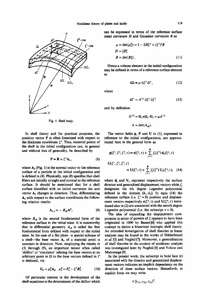
Fig. 1. Shell body.
In shell theory and for practical purposes, the position vector P is often linearized with respect to the thickness coordinate c’. Thus, material points of the shell in the initial configuration can, in general and without loss of generality, be described by
P=R+r3A3, (8)
where A, (Fig. 1) is the normal vector to the reference surface of a particle in the initial configuration and is defined in (4). Physically, eqn (8) specifies that shell fibers are initially straight and normal to the reference surface. It should be mentioned that for a shell surface identified with an initial curvature the unit vector A, changes in direction. Thus, differentiating A, with respect to the surface coordinates the follow- ing relation results:
A,., = - 4#, (9)
where B,@ is the second fundamental form of the reference surface in the initial state. It is noteworthy that in differential geometry A, is called the first fundamental form defined with respect to the initial state. In the case of a flat plate-a special subcase of a shell-the base vector A, of a material point is constant in direction. Now, employing the results in (3) through (9), an important tensor often called ‘shiftor’ or ‘translator’ relating the base vectors at an arbitrary point in R to the base vectors defined in r is deduced, viz.
Of particular interest in the development of the shell equations is the determinant of the shiftor which
can be expressed in terms of the reference surface mean curvature H and Gaussian curvature B as
p = de+:) = 1 - 2Ht3 + (t3)*B
H=fB:
B = det(B;). (11)
Hence a volume element in the initial configuration may be defined in terms of a reference surface element as
where
(12)
dr = A”*dt’dt*
and by definition
(13)
G”* = G,xG,.G, = /iA”*
A = det(AaB).
The vector fields p, P and U in (1), expressed in reference to the initial configuration, are approxi- mated here in the general form as
WC”, e*, r3, t)
= U(5”, t) + 5 L(?) WV, r), (14) r-1
where d, and U, represent respectively the surface director and generalized displacement vectors whilef, designates the rth degree Legendre polynomial defined in the domain [h,,h,]. In eqns (14) the reference surface (i.e. r3 = 0) position and displace- ment vectors respectively r(r”, t) and U(C”. t) intro- duced also in (2) are associated with the xeroth degree Legendre polynomial (i.e. the subscript r = 0).
The idea of expanding the displacement com- ponents in series of powers of c appears to have been originated in 1890 by Basset [6] who applied this concept to derive a linearized isotropic shell theory. An extended investigation of shell theories in linear analysis may be found in the works of Hilderbrand et al. [3] and Naghdi [A. Moreover, a generalization of shell theories in the context of nonlinear analysis was investigated later by Naghdi [8] and Yokoo and Matsunaga [9].
In the present work, the subscript in bold face (r) associated with the director and generalized displace- ment vectors indicates an implicit dependency on the direction of these surface vectors. Henceforth, in explicit form we may write
120 KAMAL A.
For instance, the components of the generalized displacements in the summation terms in (14) can be expressed as
(15) r,o = 1
Thus, the subscripts (i) associated with the italic r should be specified in agreement with the directions defined by the surface displacement vectors. Now, in (15) the limiting integer values R(,), Ru, and &, are not necessarily equal. The choice of the order merely depends on the kinematical approximation favored (note that in general 4,) = Z$)). As an example consider a consistent second order theory, where the displacement components in rectangular Cartesian system are given, in view of (14) and (15), by
0, = u, +A UI, +h u12
02 = u2 +A u2, +h u22
~s=~,+.h~,,+fi~,,~ (16)
which clearly shows that for this choice of kine- matical approximation RuJ = R(,, = J+,, = 2 (see Meroueh [5]).
Some authors have also considered the case where r(,, and rC2) are given the values 1 and 3 and rcn = 0 and 2 (see [lo, 1 l]), thus neglecting in-plane modes of deformations. Consequently, divers types of theories may be adopted and implemented by appropriately defining the values and the ranges of rCo.
Lo et al. [l] refer to various theories as level (N) theories. In this paper, different levels of the theory will be distinguished by the notation
R =mn, (17)
where m specifies the order of approximation of the in-plane displacements keeping in mind that RI, = R2) and n describes the degree of approxi- mation of the transverse displacement.
Resultant forces and governing equations
There exist a number of ways to derive the re- sultant stresses and equilibrium equations for plates and shells based on various conjugate stress and strain tensors. In particular, one may adopt a Eu- lerian or a Lagrangian description. In the former case all field quantities and equations are derived with respect to the current configuration and in the latter formulation all static and kinematical variables are referred to the initial configuration. It is noted that in numerical work the Lagrangian description is
t The scalar product of two tensors de&d by K..U is a scalar, for instance in the rectangular Cartesian system K..IJ = $U,. $ By abuse of terminology, we call resultant stresses w
and III, although in the literature m, is often called the stress couple.
characterized as a total Lagrangian formulation when the initial configuration is defined at time t = 0 and is referred to as the updated Lagrangian formu- lation when the field quantities are determined based on the last calculated configuration. The choice of formulation merely depends on the problems considered.
In continuum mechanics, for a three-dimensional solid acted upon by a surface traction vector f and body force B, the exact statement of the principle of virtual work based on Lagrangian description is
s n T+dn=~$%Jd/L + jnB.cWdn (18)
where dG as defined in (12) and dA are volume and surface elements at the initial configuration (an = Xl+ UaR_ C.kQ)t. It is recalled that the ini- tial configuration may not necessarily be character- ized at time t = 0. The quantity T = G,T’ is the first nonsymmetric Piola-Kirchhoff stress tensor and F = giGi is the deformation gradient. The internal virtual work in (18) may also be postulated in terms of the symmetric Piola-Kirchhoff stress tensor and its conjugate strain tensor.
Starting from the three-dimensional virtual work formulation given in (18) we may obtain the shell resultant stresses and applied forces. Indeed, using (lo)-(14) and the left hand side term in (18) we arrive at
S[ 5 WW,, + 5 m.SU, df, r r-0 r-1 1 where the resultant stresses are defined ass
m= h2f;T3pdr3, s hl
(19)
(20)
where r=0,1,2,. . . , R. By (“) we designate the partial derivative with respect to the convected coor- dinates ca, whereas ( )’ indicates the derivative with respect to c3. The covariant derivative of field vari- ables follows the usual rules defined in tensor analysis
(see [121). Similarly, noting that t = N-T the terms including
the traction vector and body force in (18) become
II
Z[S r-o r (q,+B,)*WdF +/~rt,.Wdr], (21)
in which the following have been introduced
e=f,tw/ at Vrl,h21
Nonlinear theory of plates and shells 121
(22) shells with arbitrary geometry and for a wide class of materials can be cast in the form
with A*liI,+k,+&=rh, on r
and where dr in (21) is the element boundary of r and GM are simply contravariant components of the metric tensor in the initial state of the shell previously defined in eqn (5). The quantity W is introduced to take into account a variable thickness [El].
For later purposes, we may also record the quan- tities in (20) and (22) in component form as follows:
mi,,, = s h2f;,,,‘I’3.Aip de’ hl
and
t:,, = s h* Cf,,,,t.A’N=v,& dC3 hl
B:,,, = 1 h2 Cf,,,B*A’d dt3, (23) hl
where r(,,=O, 1,2 ,..., q,,. It is important to realize that in the results just
outlined, the appearance of a repeated index referring to the subscripts (i) associated with the subscript r of the Legendre polynomials and the superscripts i of the basis vectors does not imply summation.
Equating (19) and (21) and employing the Gauss theorem, the shell equilibrium equations and bound- ary conditions for consistent and inconsistent kine- matical formulations expressed in general form are
A*M,+B,+a=m, on r
M;v =t, on ar, (24)
where 0 < r 6 R and A = A” a/aca. Because these equations are based on a Lagrangian description, the incremental form need not be rederived, and these may be obtained by simply superposing with a dot ( ’ ) (representing time-like derivatives) all quantities subscripted with r in (24). It is also noted that the partial derivative as well as the covariant derivative of a vector or tensor follow the standard rules defined in tensor analysis. Thus, the incremental equations of
[email protected]=t, on ar.
For future reference we present the components of the equilibrium equations (24) in the following manner:
Af:;,,a - M$, Bt + B&, + q&, = m&,
a3 a8 3 3_ 3 Mq,,la + Mr,p,B.s + 4(,, + qr<a, - rn,,, on r
AC&v, = f!@, M”3v =t’ ‘(3) @. ,,,, on ar,
wherero=0,1r2 ,..., handro,=0,1,2 ,..., I$,,. A vertical stroke denotes covariant differentiation with respect to the undeformed metric and Bar are the components of the curvature tensor defined by the relation (9). We note that although the equations in component form are cumbersome, their inter- pretation is rather straightforward.
Constitutive relations for shells
What follows is the introduction of the incremental relations entering in the formulation of shell struc- tures for which the initial geometry is known.
The incremental constitutive equations presented subsequently are valid for a wide class of in- crementally linear materials and can be expressed in general three-dimensional form as
+=H:R, (25)
where H represents the three-dimensional incremen- tal moduli. For finite strains and large deformations, these moduli are in general dependent on the current stresses, displacements and history parameters. In component form the fourth order tensor is defined as
H = H’~G,g,&G,. (26)
Thus, in view of (20), (25) and (26) the incremental stress resultants can be cast in the form
while the two-dimensional incremental moduli for the shell are given explicitly by
s
hz HN ~uPl~1 = f;,,,&,(A’G’* .H. .G’Ak)p dr’ (28)
hI
122
and
KAMAL A. Maaouau
noteworthy that for the plane strain case the elastic potential proposed is strongly elliptic (for an account on the ellipticity conditions see Knowles and Sternberg [13]). This latter condition is imposed merely to avoid instabilities which may add difficulties in evaluating the kinematical behavior of the sample problems considered in further parts of this paper.
Although we have considered only nonlinear elas- tic materials in this work it should be emphasized that the aforementioned theory is not limited to such constitutive models. Indeed, shell problems including hypoelastic and elasto-plastic constitutive laws are also being investigated by the author.
The existence of a strain energy density W offers the possibility of reconstructing the resultant stresses directly from a quantity defined as the surface density function which may be obtained by appropriately integrating the material function with respect to the thickness, namely:
@, = &.4JA’
e.3 = C%*WA’, (29)
wherer(,,=0,1,2 ,..., ~oands,,,=0,1,2,...,S,,,.
It is clear that eqns (27) are linearly dependent on the increment of the generalized vectors d,. The advantage of this feature will be obvious in the numerical formulation.
Constitutive equations for nonlinear compressible materials
Of special interest in this paper are compressible hyperelastic materials for which a strain energy func- tion exists. A general form of an energy density function for rubber-like materials is presented, namely:
w = M(J) + c &,(I - 3)“(ZZ - 3)“(J - 1)” (30) “,U.W
A<0 and ,liy++(J)=-co, _
where Z, ZZ and J* are the invariants of the Cauchy-Green deformation tensor. The latter condi- tions simply insure a singular behavior of the mate- rial. Indeed, we see that the function Win (30) meets the growth condition which requires an infinite amount of energy to reduce the body volume to zero. In practice, to avoid mechanical types of failures, one may also apply the ellipticity conditions outlined by Knowles and Stemberg [13] to a specific material model.
Rivlin [14] has previously proposed an energy density function of the strain invariants composed of the terms under the summation sign on the right hand side of (30). Similar types of energy functions have also been advanced by Ogden [15] who has shown that particular cases of (30) predict quite well experi- mental applications on rubber-like materials. A for- mal and practical study of nonlinear elastic materials is of interest here. For an extensive development on the mathematical requirements of the existence, con- vexity and ellipticity conditions the reader is referred to the works of Ball [16], Oden and Kikuchi [17] and Oden [18].
In what follows a specific strain energy function derived from (30) for finite plane deformations of a compressible hyperelastic solid is proposed, namely:
W=(X+p)-(lnJ+J-Z)+(ji/2)(1-2J), (31)
in which 1 and ji designate respectively the Lame and shear modulus constants of elasticity. The function in (31) is constructed in such a form as to yield the two-dimensional elastic moduli upon linearization. It can be further shown that in the limit as J-P 1 and Z + 2 the function W and the stresses are zero. It is
(32)
where p given in (11) accounts for the shell curvature. Thus the variational principle may be formulated by employing the following definitions of the resultant stresses
aY mr=G’ (33)
Taking into account the parameters introduced in (29), the relations in (33) can be cast as follows:
ay W=ae,.
av m,=Ky (34)
where r=O, 1,2,. . . , R. Similarly, these quantities may be expressed in component form as
av jp =- ‘0) de,+
ay ml,,, = -
Wc,,3i (35)
and r,,=O,1,2 ,..., 4,. Finally, for a nonlinear elastic material structure
which admits the existence of an energy density function W, the shell incremental moduli are given by
H”k’ a*y ‘(I)‘(‘) = ae,fj,,ae,,,' (36)
Nonlinear theory of pIates and shells 123
These are of course formulated on the basis of various orders of kinematical approximations. It should be mentioned that the parameters in (29) and (33)-(35) are the generalized strain-like quantities and do not represent strain components.
3. FINITE ELEMENT ANALYSIS FOR PLATES AND SHRLLS
Fotmulation
Rome problem models including geometrical and physical nonlinear&s are examined employing the finite element method. In particular, semi-infinite plate and shell problems are investigated. Never- theless, we shall present the finite element equations in general form valid for shell and plate analyses. The interest here is focussed on studying displacement, stress and strain behaviors resulting from consistent and inconsistent kinematical approximations. Lower and progressively higher order generalized displace- ments arc accounted for in the theory to investigate plate and shell problems. The lower order theories wili be specified by R = 11, 12, 13 and 31 and the higher order ones by R = 33,32,23 and 22 (we recall that in regard to the expression R = mrr, we have t(,, = tc2) = 0, 1, . . ., m and rC3) = 0, 1, . . . , n).
It is emphasized that the choice of analysing semi- infinite structures is rather due to their geometrical simplicity.
As in any nonlinear calculation, the loading and unloading (elastic-plastic) behavior is in general asso- ciated with an incremental process. Hence, in what follows we establish the incremental equations uti- lized in the numerical scheme. In particular a linear incremental method is adopted throughout the anal- ysis. Furthermore, the incremental punters of the principle of virtual work defined by (19) and (21), to lowest order, is employed for plate and shell prob- lems
= ?0 Jr]{4 + R>*W,,l dr, (37)
while the generalized strain-like quantities are given
by
@)m = (AI*U,,,)A’
and
ts,, = (A, *U,)A’. (38)
It is noteworthy that the shell finite element may also be formulated employing the concept of degener- ate shell theory (for account see Hughes and Liu [19] and Bathe and Bolourchi [20]),
Now, the derivation of the incremental counterpart of the shell traction and body forces given in eqns (22) is straightforward. The expression for the in- crement of the variational principle in terms of the two-dimensional incremental moduli is obtained by substituting (27) into (37) and taking into account (28)-(29) and (38), we arrive at
(39)
It is important to realize that these equations are linearly dependent on the generalized incremental displacements. Furthermore, consistent and inconsis- tent kinematical approximations of any order can be applied to the formulation by properly truncating the series keeping in mind that the choice of &, Rcl and & depends on the particular theory adopted.
Subsequently, the increment of the variational principle (39) shall form the basis for the finite element analysis of the problems. The variational relation expressed in (39) may be easily adopted to linear analyses. For small strain and small defor- mation theory the incremental shell moduli ~~~,~ reduce to the well-known two-dimensional elastic stiffness matrix of the shell structure.
The finite element formulation is characterized by a total Lagrangian description. The shell region r is discretized into finite number of elements and the ~~~b~urn equations resulting from (39) are applied to each element. The complete shell structure equi- librium is assumed established by the requirement of nodal equilibrium and compatibility of the displace- ment method.
In each of the finite elements, the generalized ~spla~ments are represented in terms of the nodal generalized displacements by
U,=N,U: r-0,1,2 ,..., R, (40)
where N, is the interpolation model corresponding to the u-node in the element. And the virtual generalized displa~ments are expressed in terms of the nodal virtual generalized displacements simply as
6U, = N&J;. (41)
The isoparametric concept is adopted and hence the shell curvilinear coordinates as well as the gener- alized displacements @I)-(41) are discretized with the same shape functions. Moreover, only Co continuity is required given that the field variable is continuous at element interfaces. In component form the virtual
124 KNML A. M~ROIJEH
displacements in (41) are
where r,,)=O,1,2 ,..., &,. Substituting (42) into (38) and the results into (39),
the element matrix equation takes the following form
K’U=Q’, (43)
where K’ designates the element incremental stiffness matrix and U and Q’ denote the incremental gener- alized element displacement and force vectors. Upon assembly of eqns (43) over each element the global matrix equation is obtained.
Results
The accuracy of the plate finite element solutions employing the various aforementioned shell theories will be assessed by direct comparison with the finite element results based on the exact equations of a continuum, whereas for the shell models, the sol- utions obtained from the various kinematical theories are compared considering that the displacement theory involving R = 33 exhibits high accuracy as is shown in [S]. A linear incremental solution technique for the nonlinear problems is achieved by considering a number of incremental load steps. And the true equilibrium state resulting from the internal stresses and external loads is reached by applying an iterative process at each incremental load step using a simple Newton-Raphson method.
For simplicity semi-infinite plates and shells are investigated throughout this work. Thus, the plain strain condition is imposed perpendicular to the plane of deformation. The lack of literature on the present type of nonlinear analysis leads us to formu- late and utilize the exact two-dimensional plate finite element counterpart of the same problems. There- fore, two computer programs for plates are devel- oped:
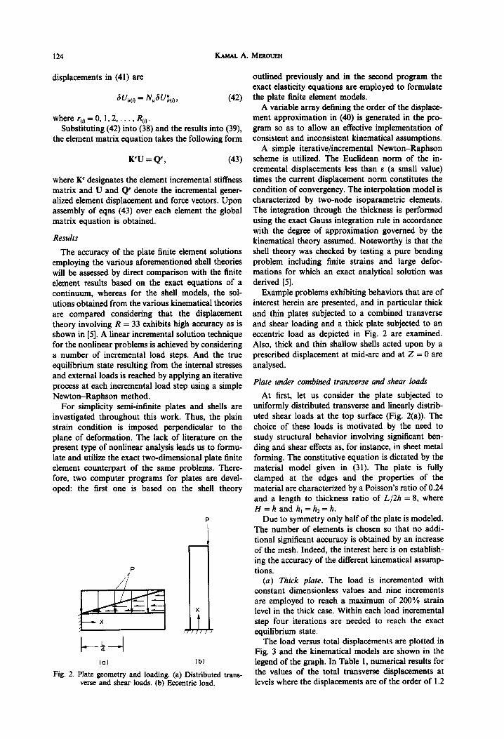
Fig. 2.
the first one is based on the shell theory
(al (b)
Plate geometry and loading. (a) Distributed trans- verse and shear loads. (b) Eccentric load.
outlined previously and in the second program the exact elasticity equations are employed to formulate the plate finite element models.
A variable array defining the order of the displace- ment approximation in (40) is generated in the pro- gram so as to allow an effective implementation of consistent and inconsistent kinematical assumptions.
A simple iterative/incremental Newton-Raphson scheme is utilized. The Euclidean norm of the in- cremental displacements less than E (a small value) times the current displacement norm constitutes the condition of convergency. The interpolation model is characterized by two-node isoparametric elements. The integration through the thickness is performed using the exact Gauss integration rule in accordance with the degree of approximation governed by the kinematical theory assumed. Noteworthy is that the shell theory was checked by testing a pure bending problem including finite strains and large defor- mations for which an exact analytical solution was derived [5].
Example problems exhibiting behaviors that are of interest herein are presented, and in particular thick and thin plates subjected to a combined transverse and shear loading and a thick plate subjected to an eccentric load as depicted in Fig. 2 are examined. Also, thick and thin shallow shells acted upon by a prescribed displacement at mid-arc and at Z = 0 are analysed.
Plate under combined transverse and shear loads
At first, let us consider the plate subjected to uniformly distributed transverse and linearly distrib- uted shear loads at the top surface (Fig. 2(a)). The choice of these loads is motivated by the need to study structural behavior involving significant ben- ding and shear effects as, for instance, in sheet metal forming. The constitutive equation is dictated by the material model given in (31). The plate is fully clamped at the edges and the properties of the material are characterized by a Poisson’s ratio of 0.24 and a length to thickness ratio of L/2h = 8, where H = h and h, = h2 = h.
Due to symmetry only half of the plate is modeled. The number of elements is chosen so that no addi- tional significant accuracy is obtained by an increase of the mesh. Indeed, the interest here is on establish- ing the accuracy of the different kinematical assump- tions.
(a) Thick plate. The load is incremented with constant dimensionless values and nine increments are employed to reach a maximum of 200% strain level in the thick case. Within each load incremental step four iterations are needed to reach the exact equilibrium state.
The load versus total displacements are plotted in Fig. 3 and the kinematical models are shown in the legend of the graph. In Table 1, numerical results for the values of the total transverse displacements at levels where the displacements are of the order of 1.2
Nonlinear theory of plates and shells 125
PLATE DISPLACEMENTS Al X=l/Z.D Dirtrlbuted Tmnrvwr~ and Shear Loads
/
_. ._ _ __ _ __
Fig. 3. Load vs displacement at Z/h = - 1.
: ,..’
. ..”
/
Thick Case . EXACT . *pp R-J3
0 !PP_R%____.
q ws .._.... D &pprt=ztJ
v *ppRS?_. 0 *pp. R=,2
. AJlJF!=l3 .-.-.- * &R-J’ ---
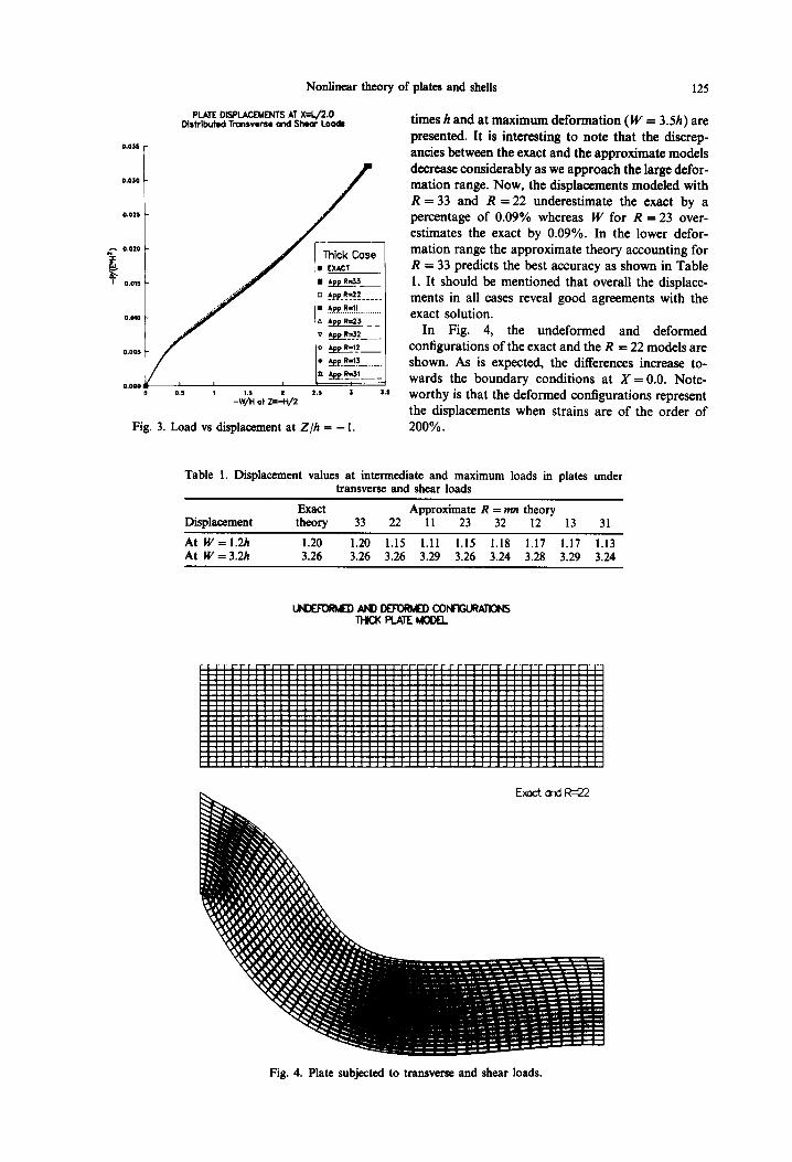
times h and at maximum deformation (W = 3.5h) are presented. It is interesting to note that the discrep- ancies between the exact and the approximate models decrease considerably as we approach the large defor- mation range. Now, the displacements modeled with R = 33 and R = 22 underestimate the exact by a percentage of 0.09% whereas W for R = 23 over- estimates the exact by 0.09%. In the lower defor- mation range the approximate theory accounting for R = 33 predicts the best accuracy as shown in Table 1. It should be mentioned that overall the displace- ments in all cases reveal good agreements with the exact solution.
In Fig. 4, the undeformed and deformed configurations of the exact and the R = 22 models are shown. As is expected, the differences increase to- wards the boundary conditions at X = 0.0. Note- worthy is that the deformed configurations represent the displacements when strains are of the order of 200%.
Table 1. Displacement values at intermediate and maximum loads in plates under transverse and shear loads
Displacement Exact Approximate R = mn theory theory 33 22 11 23 32 12 13 31
At W=l.U 1.20 1.20 1.15 1.11 1.15 1.18 1.17 1.17 1.13 At W=3.2/1 3.26 3.26 3.26 3.29 3.26 3.24 3.28 3.29 3.24
Fig. 4. Plate subjected to transverse and shear loads.
KARL A. MBROUEH
Sexmd PIOLA-KIRCHHOFF STRESS Dlrtrlbuted Tunrvws~ and Show Loads
Distributions at X=L/&D at ZDOX MAX STRAIN
Fig. 5. Normal stress vs thickness (distributed loads).
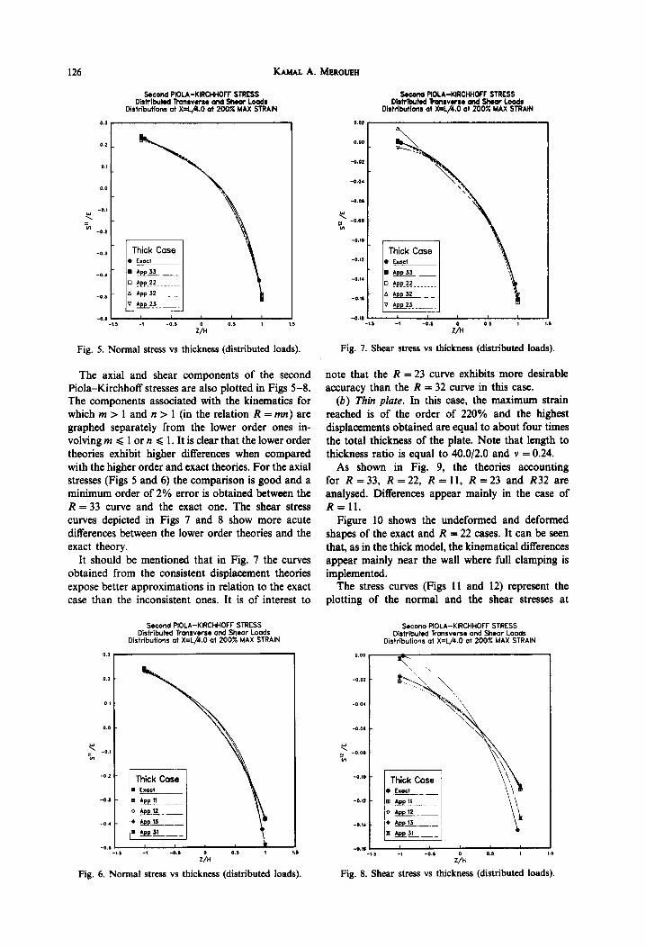
The axial and shear components of the second Piola-Kirchhoff stresses are also plotted in Figs 5-8. The components associated with the kinematics for which m > 1 and n > 1 (in the relation R = mn) are graphed separately from the lower order ones in- volving m c 1 or n Q 1. It is clear that the lower order theories exhibit higher differences when compared with the higher order and exact theories. For the axial stresses (Figs 5 and 6) the comparison is good and a minimum order of 2% error is obtained between the R = 33 curve and the exact one. The shear stress curves depicted in Figs 7 and 8 show more acute differences between the lower order theories and the exact theory.
It should be mentioned that in Fig. 7 the curves obtained from the consistent displacement theories expose better approximations in relation to the exact case than the inconsistent ones. It is of interest to
Second PIOLA-KIRCHHOFF STRESS Distributed Transverse and Shear Loads
Distributions at X=L/4.0 at 200X MAX STRAIN
-0.3 -1.) -‘ -a* $4 0.1 1
Fig. 6. Normal stress vs thickness (distributed loads).
Second PIOLA-KIRCHHOFF STRESS DktrlbtM i+anrvwu and Shmr Loads
Dirtrlbutlons at X+/4.0 at 200% MAX STRAIN
Fig. 7. Shear stress vs thickness (distributed loads).
note that the R = 23 curve exhibits more desirable accuracy than the R = 32 curve in this case.
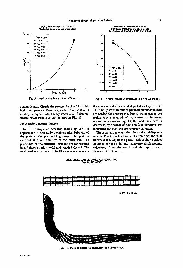
(b) Thin plate. In this case, the maximum strain reached is of the order of 220% and the highest displacements obtained are equal to about four times the total thickness of the plate. Note that length to thickness ratio is equal to 40.0/2.0 and v = 0.24.
As shown in Fig. 9, the theories accounting for R = 33, R = 22, R = 11, R 3: 23 and R32 are analysed. Differences appear mainly in the case of R = 11.
Figure 10 shows the undeformed and deformed shapes of the exact and R = 22 cases. It can be seen that, as in the thick model, the kinematical differences appear mainly near the wall where full clamping is implemented.
The stress curves (Figs 11 and 12) represent the plotting of the normal and the shear stresses at
Second PIOLA-KIRCHHOFF STRESS Distributed Transverse and Shear Loads
Distributions at X=L/4.0 at 200X MAX STRAIN
-0.n 1 -1.1 -I -0.3 ZiH 0.) I ,
Fig. 8. Shear stress vs thickness (distributed loads).
Nonlinear theory of plates and she& 127
Fig. 9. Load vs displacement at Z/h = - I.
smondFioLA-K-SIRESS DbtdbUM~VUSOand~LW$
Dlstributlms ot X=L,kO at 220% MAX STRAIN
Fig. 11. Normal stress vs thickness (distributed loads).
quarter length. Clearly the stresses for R = 11 exhibit high discrepancies. Moreover, aside from the R = 33 model, the higher order theory where R = 32 demon- strates better remits as can be seen in Fig. 11.
Plate under eccentric loading
In this example an eccentric load (Fig. 2(b)) is applied at x = L to study the kinematical behavior of the plate in the postbuckling range. The plate is clamped at X = 0 and free at the other end. The properties of the structural element are represented by a Poisson’s ratio v = 0.3 and length L/2h = 8. The total load is subdivided into 1X increments to reach
the maximum displacement depicted in Figs 13 and 14. Initially seven iterations per load incremental step are needed for convergency but as we approach the region where reversal of transverse displacement occurs, as shown in Fig. 13, the load increment is decreased by a factor of half and four iterations per increment satisfied the convergency criterion.
The calculations reveal that the total axial displace- ment at X = L reaches a value of seven times the totai thickness (i.e. 2h) of the plate. Table 2 shows values obtained for the axial and transverse displacements calculated from the exact and the approximate theories at Z/h = + 1.
Fig. 10. Plate subjected to transverse and shear loads.
C.A.S. 29114
128 K.A~AL A. MERO~
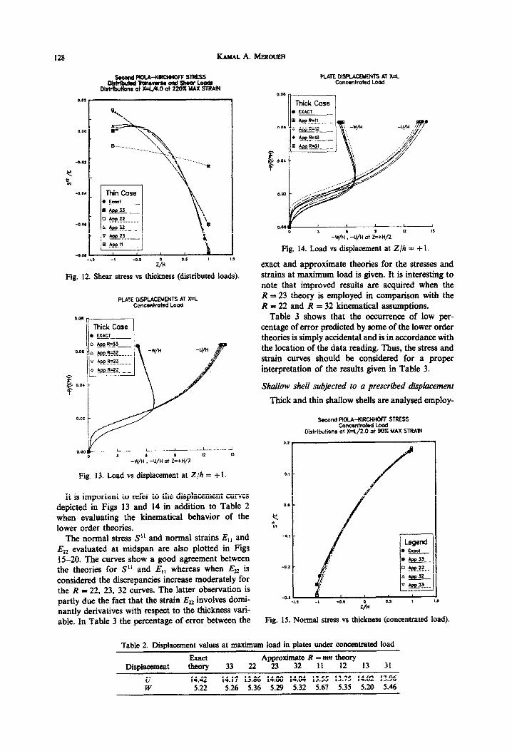
Fig. 12, Shear stress vs thickness (distributed loads).
PLATE DISPLACEMENTS AT X=L Ccncmkatsd Load
Thick Case , EXACT --- l
__.-. i- , , ____.L_-.._ _I
Fig. 13. Load vs displacement at Z/h = + I.
It is important to refer to the displacement curves depicted in Figs 13 and 14 in addition to Table 2 when evaluating the kinematical behavior of the lower order theories.
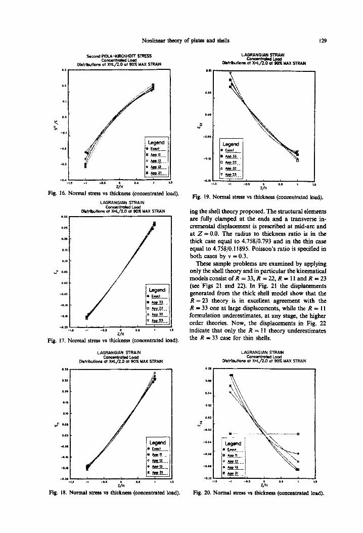
The normal stress S” and normal strains E,, and Ezz evaluated at midspan are also plotted in Figs 15-20. The curves show a good agreement between the theories for S” and E,, whereas when Ez2 is considered the discrepancies increase moderately for the R = 22, 23, 32 curves. The latter observation is partly due the fact that the strain Eu involves domi- nantly derivatives with respect to the thickness vari- able. In Table 3 the percentage of error between the
PLATE DISPLAWNTS AT X=L conc*ntmt.d LOod
@.W 0 1 -W/N: -U/H at Z:+H/2 ‘* ”
Fig. 14. Load vs displacement at Z/h = + 1.
exact and approximate theories for the stresses and strains at maximum load is given. It is interesting to note that improved results are acquired when the R = 23 theory is employed in comparison with the R = 22 and R = 32 kinematical assumptions.
Table 3 shows that the occurrence of low per- centage of error predicted by some of the lower order theories is simply accidental and is in accordance with the location of the data reading. Thus, the stress and strain curves should be considered for a proper interpretation of the results given in Table 3.
Shallow shell subjected to a prescribed displacement
Thick and thin shallow shells are analysed employ-
Fig. 15. Normal stress vs thickness (concentrated load).
Table 2. Displacement values at maximum load in plates under concentrated load
Exact Approximate R = mn theory Diisplacement theory 33 22 23 32 II 12 13 31
u 14.42 14.17 13.86 14;00 14.04 13.55 13.75 14.02 13.96 w 5.22 5.26 5.36 5.29 5.32 5.67 5.35 5.20 5.46
129
s.wnd PmA-xstctlNaff STRESS
Oirtributionr %=$i?tt% MAX STRAIN
Fig. 16. Normal stress vs thickness (conoentnitwi Ioad).
LAGRANGIAN STRAIN
lMrikrtionr %?%%t%! MAX STRAIN
Fig.
-1,s -1 as 2% as t
17. Normal stress vs thickness (concentrated load).
LAGRANGIAN STRAIN -Load
Wtrtbuttons ot X=&/2.0 at 90% MAX STRAIN
0.n
0.m
0.11
cl.*
-= LO$
0.00
-0.05
-aI0
-au
am ‘LS -1 -03 25 aa , IS
Fig. 18. Normal stress vs thi&ness (concentrated load),
Distribution8 at X=l&G at 90% MAX STRAIN
Fig. 19. Norma1 stress vs thickness (concentrated foad).
ing the shell theory proposed. The structural elements are fully clamped at the ends and a transverse in- cremental ~sp~~nt is prescribed at mid-arc and at Z = 0.0. The radius to thickness ratio is in the thick case equal to 4.75830.793 and in the thin case equal ta 4758/O. 11895. Poisson’s ratio is specified in both cases by v = 0.3.
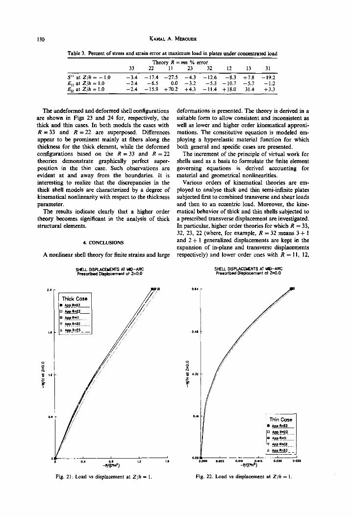
These sample problems are examined by applying only the shell theory and in particular the kinematical mod&consistofR =33,R =2&R = IlandR =23 (see .Figs 21 and 22). In Fig. 21 the displacements generated from the thick shell model show that the R = 23 theory is in excellent agreement with the R = 33 one at large displacements, while the R = 11 formulation underestimates, at any stage, the higher order theories. Now, the displacements in Fig. 22 indicate that only the R = I1 them-y underestimates the R = 33 case for thin shells. _
LAGRANGIAN STRAIN
Dist&utiom %$%tL MAX STRAtN
Fig. 20. Normal stress vs thickness (concentrated bad).
130 KAMAL A. MEROUEH
Table 3. Percent of stress and strain error at maximum load in plates under concentrated load
Theory R = mn % error 33 22 11 23 32 12 13 31
S” at Z/h = - 1 ’ 0 -3.4 -17.4 -27.5 -4.3 -12.6 -8.3 +7.8 -19.2 E,, at Z/h = 1.0 -2.4 -6.5 0.0 -3.2 -5.3 -10.7 -5.7 -1.2 E,, at Z/h = 1.0 -2.4 -15.9 +70.2 +4.3 -11.4 +18.0 31.4 +3.3
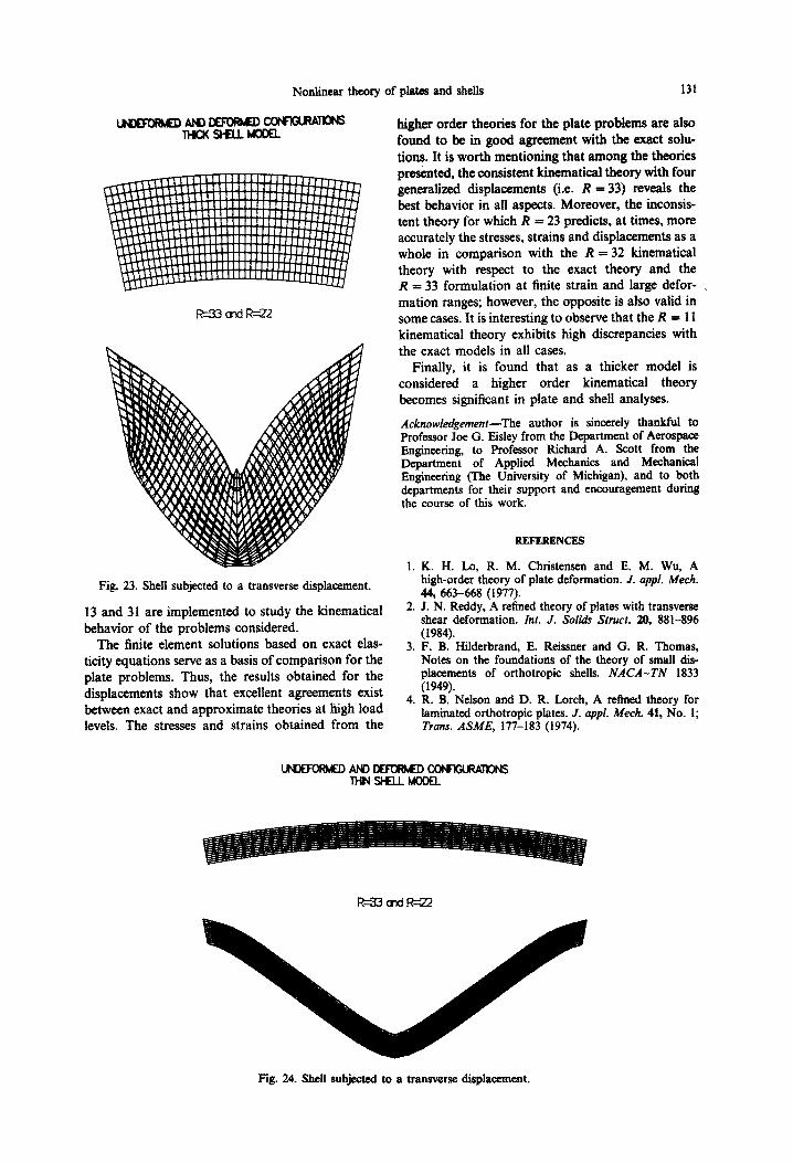
The undeformed and deformed shell configurations are shown in Figs 23 and 24 for, respectively, the thick and thin cases. In both models the cases with R = 33 and R = 22 are superposed. Differences appear to be prominent mainly at fibers along the thickness for the thick element, while the deformed configurations based on the R = 33 and R = 22 theories demonstrate graphically perfect super- position in the thin case. Such observations are evident at and away from the boundaries. It is interesting to realize that the discrepancies in the thick shell models are characterized by a degree of kinematical nonlinearity with respect to the thickness parameter.
The results indicate clearly that a higher order theory becomes significant in the analysis of thick structural elements.
4. CONCLUSIONS
A nonlinear shell theory for finite strains and large
SHELL DISPLACEMENTS AT MID-ARC SHELL DISPLACEMENTS AT MID-ARC Prescribed Displacement at Z=O.O Prescribed Displacement at 20.0
Fig. 21. Load vs displacement at Z/h = 1.
deformations is presented. The theory is derived in a suitable form to allow consistent and inconsistent as well as lower and higher order kinematical approxi- mations. The constitutive equation is modeled em- ploying a hyperelastic material function for which both general and specific cases are presented.
The increment of the principle of virtual work for shells used as a basis to formulate the finite element governing equations is derived accounting for material and geometrical nonlinearities.
Various orders of kinematical theories are em- ployed to analyse thick and thin semi-infinite plates subjected first to combined transverse and shear loads and then to an eccentric load. Moreover, the kine- matical behavior of thick and thin shells subjected to a prescribed transverse displacement are investigated. In particular, higher order theories for which R = 33, 32, 23, 22 (where, for example, R = 32 means 3 + 1 and 2 + 1 generalized displacements are kept in the expansion of in-plane and transverse displacements respectively) and lower order ones with R = 11, 12,
Fig. 22. Load vs displacement at Z/h = I.
Nonlinear theory of plates and shells 131
Fig. 23. Shell subjected to a transverse displacement.
13 and 31 are implements to study the kinematical behavior of the problems considered.
The finite element solutions based on exact elas- ticity equations serve as a basis of comparison for the plate problems. Thus, the results obtained for the displacements show that excellent agreements exist between exact and approximate theories at high load levels. The stresses and strains obtained from the
higher order theories for the plate problems are also found to be in good agreement with the exact solu- tions. It is worth mentioning that among the theories presented, the consistent kinematical theory with four generalized displacements (i.e. R = 33) reveals the best behavior in all aspects. Moreover, the inconsis- tent theory for which R = 23 predicts, at times, more accurately the stresses, strains and displacements as a whole in comparison with the R = 32 kinematical theory with respect to the exact theory and the R = 33 formulation at tinite strain and large defer- ., mation ranges; however, the opposite is also valid in some cases. It is interesting to observe that the R = 11 kinematical theory exhibits high discrepancies with the exact models in all cases.
Finally, it is found that as a thicker model is considered a higher order kinematical theory becomes si~ifi~nt in plate and shell analyses.
Acknowledgement-The author is sincerely thankful to Professor Joe G. Eisley from the Department of Aerospace Engineering, to Professor Richard A. Scott from the Department of Applied Mechanics and Mechanical Engineering (The University of Michigan), and to both departments for their support and encouragement during the course of this work.
REFERENCES
K. H. Lo, R. M. Christensen and E. M. Wu, A high-order theory of plate deformation. J. appf. Me&. 44,663-668 (1977). J. N. Reddy, A refined theory of plates with transverse shear deformation. ht. J. S&h Sfmct. 20, 881-896 (1984). F. B. Hilderbrand, E. Reissner and G. R. Thomas, Notes on the foundations of the theory of small dis- placements of orthotropic shells. NACA-TN 1833 (1949). R. B. Nelson and D. R. Larch, A refmed theory for laminated orthotropic plates. J. appl. Meek. 41, No. I; Trans. ASME, 177-183 (1974).
Fig. 24. Shell subjected to a transverse displacement.
132 KAMAL A. Mwoue~
5. K. A. Meroueh, Gn a formulation of a nonlinear theory of plates and shells with applications. Cotnpur. Strucr. 24,691-705 (1986).
6. A. B. Basset, On the extension and flexure of cylindrical and spherical thin elastic shells. Phil. Trans. R. Sot. 15. (Land.), Ser. A 181, 433-480 (1890).
7. P. M. Naghdi, Foundations of elastic shell theory. In Progress in Solids Mechanics (Edited by 1. N. Sneddon), no. l-90. Vol. IV, Amsterdam (1963). 16.
8. k M. Naghdi, Theory of plates and shells. In Hundbush der Phvsics vi. al2 (Edited bv S. Fliigge), DP. 425-640. Spring&, Berlin’(l971). _ -- __ 17.
9. Y. Yokoo and H. Matsunaga, A general nonlinear theory of elastic shells. Int. J. Solids Struct. 10, 261-274 (1974).
10. E. Reissner, On transverse bending of plates, including 18. the effects of transverse shear deformation. Int. J. Solids Struct. 11, 569-573 (1975).
11. T. Kant, Numerical Analysis of Thick Plates. Comput. Merh. appl. Mech. Engng. 31, l-18 (1982).
12. A. E. Green and W. Zcma, Theoretical Elasticity. 19. Clarendon, Oxford (1954).
13. J. K. Knowles and E. Stemberg, On the failure of ellipticity of the equations for finite elastostatic plane 20. strain. Arch. Rat. Mech. Anal. 63. 321-336 (1977).
14. R. S. Rivlin, Some topics in finite’elasticity. Structural
mechanics. In Proceedings of the First Symposium on Naval Structural Mechanics (Edited by J. N. Goodiey and N. J. Hoff), pp. 169-198. Pergamon, London (1960). R. W. Ogden, Large deformation isotropic elasticity: on the comlation of theory and experiment for com- pressible rubberlike solids. Proc. R. Sot. Land. A328, 567-583 (1972). J. M. Ball, Convexity conditions and existence theorems in nonlinear elasticity. Arch. Rur. Mech. Anal. 63, 337403 (1977). J. T. Gden and N. Kikuchi, Existence theory for a class of problems in nonlinear elasticity: finite plane strains for compressible hyperelastic body. TICOM Rep. 78-13, The University of Texas (1978). J. T. Gden, Finite element methods of a class of nonlinear boundary-value problems in finite elasticity. In The Mathematics of Finite Elemenls and Applications III Mapelap (1978) (Edited by J. R. Whiteman), pp. 327-339: Academic. Press, London (1979). T. J. R. Hushes and W. K. Liu. Nonlinear finite element analysis oFshells: part I. Three dimensional shells. Comput. Meth. appl. Mech. Engng 26, 331-362 (1981). K. J. Bathe and S. Bolourchi, A geometric and material nonlinear plate and shell element. Comput. Struct. 11, 23-48 (1980).

![of use of the elements plates, shells, [] This · shells SHB, grids and membranes Summarized: This document is a note of use for the voluminal modelizations plates, shells, shells](https://img.pdfslide.us/doc/110x75/5ee0e005ad6a402d666bf4b1/of-use-of-the-elements-plates-shells-this-shells-shb-grids-and-membranes-summarized.jpg)