Embed Size (px)
Citation preview

AppNote_Temp_Cntl_002.0_E5_N-H
Application Note – Pan Americas Page 1 of 13
OMRON APPLICATION NOTE Automatic PID Selection for E5_N-H
and E5_N-HT Temperature Controllers
This document explains:
Parameters used for automatic PID selection
Provides application examples using Analog inputs and using Process Value, Set Values andDeviation Values for the Selection Data.
Provides application examples using Thermocouple inputs and using Process Value, SetValues and Deviation Values for the Selection Data.
Will also show information/reaction based on the selection of PV (Process Value), SP (SetPoint) and DV (Deviation Value) when setting the “Automatic Selection Data” parameter.
Author: Keith HillDate: 2/22/2017
Cat. No H53I-E-01
AppNote_Temp_Cntl_002.0_E5_N-H
Application Note – Pan Americas Page 2 of 13
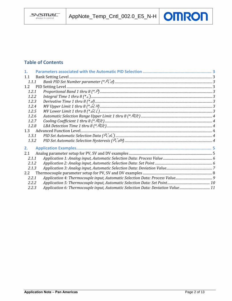
Table of Contents
1. Parameters associated with the Automatic PID Selection ........................................................ 3 1.1 Bank Setting Level ..................................................................................................................................................................... 3
1.1.1 Bank PID Set Number parameter (*.pid) ....................................................................................................................... 3 1.2 PID Setting Level ........................................................................................................................................................................ 3
1.2.1 Proportional Band 1 thru 8 (*.p) ......................................................................................................................................... 3 1.2.2 Integral Time 1 thru 8 (*.i) .................................................................................................................................................... 3 1.2.3 Derivative Time 1 thru 8 (*.d) ............................................................................................................................................... 3 1.2.4 MV Upper Limit 1 thru 8 (*.olh) ......................................................................................................................................... 3 1.2.5 MV Lower Limit 1 thru 8 (*.oll) ......................................................................................................................................... 3 1.2.6 Automatic Selection Range Upper Limit 1 thru 8 (*.aut) ....................................................................................... 4 1.2.7 Cooling Coefficient 1 thru 8 (*.aut) ................................................................................................................................... 4 1.2.8 LBA Detection Time 1 thru 8 (*.aut) ................................................................................................................................. 4
1.3 Advanced Function Level ........................................................................................................................................................ 4 1.3.1 PID Set Automatic Selection Data (pidi) ...................................................................................................................... 4 1.3.2 PID Set Automatic Selection Hysteresis (pidh) ........................................................................................................... 4
2. Application Examples .............................................................................................................. 5 2.1 Analog parameter setup for PV, SV and DV examples ................................................................................................ 5
2.1.1 Application 1: Analog input, Automatic Selection Data: Process Value ............................................................ 6 2.1.2 Application 2: Analog input, Automatic Selection Data: Set Point ...................................................................... 6 2.1.3 Application 3: Analog input, Automatic Selection Data: Deviation Value ........................................................ 7
2.2 Thermocouple parameter setup for PV, SV and DV examples ................................................................................ 8 2.2.1 Application 4: Thermocouple input, Automatic Selection Data: Process Value ............................................. 9 2.2.2 Application 5: Thermocouple input, Automatic Selection Data: Set Point .................................................... 10 2.2.3 Application 6: Thermocouple input, Automatic Selection Data: Deviation Value ..................................... 11

AppNote_Temp_Cntl_002.0_E5_N-H
Application Note – Pan Americas Page 3 of 13
1. Parameters associated with the Automatic PID Selection The following parameters are used to set up automatic PID selection, not all parameters maybe needed or viewed
depending on the application.
1.1 Bank Setting Level
1.1.1 Bank PID Set Number parameter (*.pid)
Since the unit allows up to 8 different banks each bank can have its own PID set. The user can set a specific set of PID’s for each bank or choose to automatically select the PID according to present conditions. These conditions can be based on PV (Process Value), SV (Set Point Value) or deviation from set point. Setting the Bank PID Set Number parameter (*.pid) for the bank used for this purpose to a “0” will enable the Automatic PID Selection function for that bank. Up to 8 zones can be selected, depending on how many zones are needed will determine if other PID sets can be used for other banks.
1.2 PID Setting Level
1.2.1 Proportional Band 1 thru 8 (*.p)
This parameter allows user to manually enter proportional band values for PID 1 thru 8, or by auto tuning when the PV is in that present zone. If the user uses auto tune, this value will be automatically calculated based on the auto tune calculation.
1.2.2 Integral Time 1 thru 8 (*.i)
This parameter allows user to manually enter integral time values for PID 1 thru 8, or by auto tuning when the PV is in that present zone. If the user uses auto tune, this value will be automatically calculated based on the auto tune calculation.
1.2.3 Derivative Time 1 thru 8 (*.d)
This parameter allows user to manually enter derivative time values for PID 1 thru 8, or by auto tuning when the PV is in that present zone. If the user uses auto tune, this value will be automatically calculated based on the auto tune calculation.
1.2.4 MV Upper Limit 1 thru 8 (*.olh)
This parameter allows user to manually change manipulative upper limit (%Power) for PID 1 thru 8. This is defaulted at 105% and can be lowered to limit the amount of output power at the high end.
1.2.5 MV Lower Limit 1 thru 8 (*.oll)
This parameter allows user to manually change manipulative lower limit (%Power) for PID 1 thru 8. This is defaulted at -5.0% for standard operation and -105.0 Heating/Cooling and can be raised to limit the amount of output power at the low end.

AppNote_Temp_Cntl_002.0_E5_N-H
Application Note – Pan Americas Page 4 of 13
1.2.6 Automatic Selection Range Upper Limit 1 thru 8 (*.aut)
This parameter allows user to manually change Automatic Selection Range Upper Limit for PID 1 thru 8. This is used to determine upper limit for each zone.
1.2.7 Cooling Coefficient 1 thru 8 (*.aut)
This parameter allows user to manually change Cooling Coefficient for PID 1 thru 8. This parameter is only available if heating and cooling is selected. This will allow the user to change the cooling proportional band if it differs from the heating proportional band.
1.2.8 LBA Detection Time 1 thru 8 (*.aut)
This parameter allows user to manually change LBA Detection Time for PID 1 thru 8. This parameter is only available if Loop Burnout Alarm is enabled. This will allow the user to set the detection time for a loop burnout.
1.3 Advanced Function Level
1.3.1 PID Set Automatic Selection Data (pidi)
This parameter allows user to select what the automatic selection data is based on (PV -----> Process Value, SP ----> Set Point or DV -----> Deviation Value from set point)
1.3.2 PID Set Automatic Selection Hysteresis (pidh)
PID Set automatic selection hysteresis allows the user to enter a hysteresis value for all zones.
AppNote_Temp_Cntl_002.0_E5_N-H
Application Note – Pan Americas Page 5 of 13
2. Application Examples
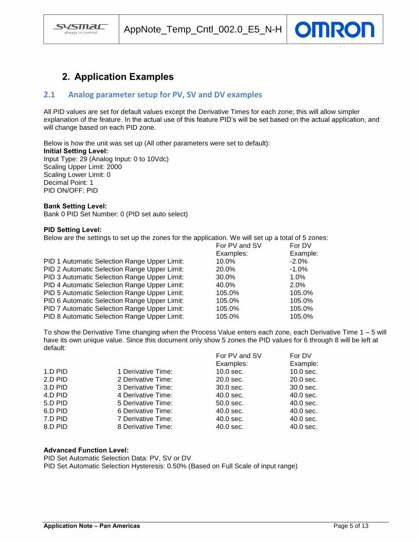
2.1 Analog parameter setup for PV, SV and DV examples All PID values are set for default values except the Derivative Times for each zone; this will allow simpler explanation of the feature. In the actual use of this feature PID’s will be set based on the actual application, and will change based on each PID zone. Below is how the unit was set up (All other parameters were set to default): Initial Setting Level: Input Type: 29 (Analog Input: 0 to 10Vdc) Scaling Upper Limit: 2000 Scaling Lower Limit: 0 Decimal Point: 1 PID ON/OFF: PID Bank Setting Level: Bank 0 PID Set Number: 0 (PID set auto select) PID Setting Level: Below are the settings to set up the zones for the application. We will set up a total of 5 zones:
For PV and SV For DV Examples: Example:
PID 1 Automatic Selection Range Upper Limit: 10.0% -2.0% PID 2 Automatic Selection Range Upper Limit: 20.0% -1.0% PID 3 Automatic Selection Range Upper Limit: 30.0% 1.0% PID 4 Automatic Selection Range Upper Limit: 40.0% 2.0% PID 5 Automatic Selection Range Upper Limit: 105.0% 105.0% PID 6 Automatic Selection Range Upper Limit: 105.0% 105.0% PID 7 Automatic Selection Range Upper Limit: 105.0% 105.0% PID 8 Automatic Selection Range Upper Limit: 105.0% 105.0% To show the Derivative Time changing when the Process Value enters each zone, each Derivative Time 1 – 5 will have its own unique value. Since this document only show 5 zones the PID values for 6 through 8 will be left at default:
For PV and SV For DV Examples: Example:
1.D PID 1 Derivative Time: 10.0 sec. 10.0 sec. 2.D PID 2 Derivative Time: 20.0 sec. 20.0 sec. 3.D PID 3 Derivative Time: 30.0 sec. 30.0 sec. 4.D PID 4 Derivative Time: 40.0 sec. 40.0 sec. 5.D PID 5 Derivative Time: 50.0 sec. 40.0 sec. 6.D PID 6 Derivative Time: 40.0 sec. 40.0 sec. 7.D PID 7 Derivative Time: 40.0 sec. 40.0 sec. 8.D PID 8 Derivative Time: 40.0 sec. 40.0 sec. Advanced Function Level: PID Set Automatic Selection Data: PV, SV or DV PID Set Automatic Selection Hysteresis: 0.50% (Based on Full Scale of input range)

AppNote_Temp_Cntl_002.0_E5_N-H
Application Note – Pan Americas Page 6 of 13
2.1.1 Application 1: Analog input, Automatic Selection Data: Process Value
This application is to show how the unit works with an analog input using an Automatic PID selection. The PID Set Automatic Selection Data will be based on the process value. Since the unit uses full scale % for Analog Input types the Automatic Selection Range values the limits used will need to be based on Scaling Upper Limit + Scaling Lower Limit. In this application we are using 0 to 2000, so full range will be 2000. Since 10% setting for the Automatic Selection Range Upper Limit for zone 1 is used we can then calculate the value. E.g. 2000 x 10% = 200. Since we are using 1 decimal point it would then be 20.0 counts.
The chart below shows the process value range for each zone in this application:
Zone Automatic Selection Range Upper Limit PV Zone Value
1 10.0% 0 - 20.0
2 20.0% 20.0 - 40.0
3 30.0% 40.0 - 60.0
4 40.0% 60.0 - 80.0
5 105.0% 80.0 - 200.0
Below shows an actual trend chart of applying several different voltages to the input to show the automatic selection process working. The chart shows when the Process Value (RED) enters each zone the Derivative Time (Light Blue) changes as well as the PID Set No. Monitor value (Orange), based on the zone requirements:
2.1.2 Application 2: Analog input, Automatic Selection Data: Set Point
Using the Set Point as the automatic selection data is very similar to using the Process Value. When using the Set Value the PID zone will be based on the set point rather than the Process Value. In the applications above the set point was always set to 0. So it was purely based on the Process Value for the zone determination. When
AppNote_Temp_Cntl_002.0_E5_N-H
Application Note – Pan Americas Page 7 of 13
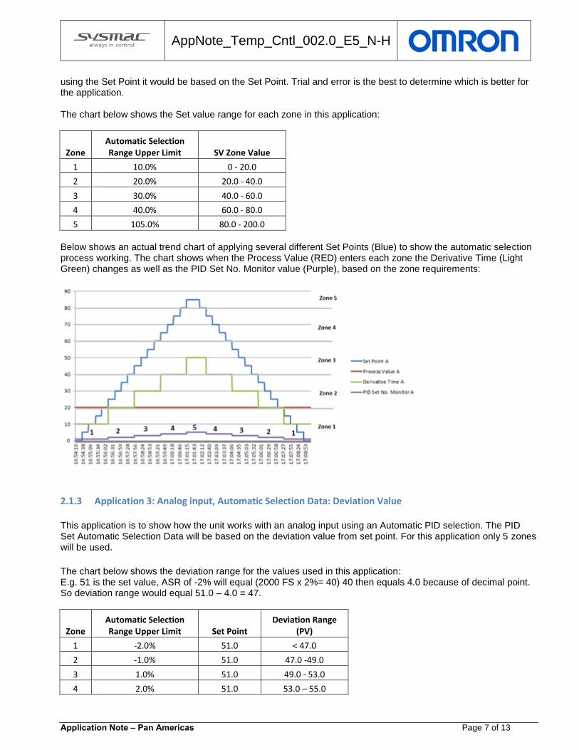
using the Set Point it would be based on the Set Point. Trial and error is the best to determine which is better for the application. The chart below shows the Set value range for each zone in this application:
Zone Automatic Selection Range Upper Limit SV Zone Value
1 10.0% 0 - 20.0
2 20.0% 20.0 - 40.0
3 30.0% 40.0 - 60.0
4 40.0% 60.0 - 80.0
5 105.0% 80.0 - 200.0
Below shows an actual trend chart of applying several different Set Points (Blue) to show the automatic selection process working. The chart shows when the Process Value (RED) enters each zone the Derivative Time (Light Green) changes as well as the PID Set No. Monitor value (Purple), based on the zone requirements:
2.1.3 Application 3: Analog input, Automatic Selection Data: Deviation Value
This application is to show how the unit works with an analog input using an Automatic PID selection. The PID Set Automatic Selection Data will be based on the deviation value from set point. For this application only 5 zones will be used.
The chart below shows the deviation range for the values used in this application: E.g. 51 is the set value, ASR of -2% will equal (2000 FS x 2%= 40) 40 then equals 4.0 because of decimal point. So deviation range would equal 51.0 – 4.0 = 47.
Zone Automatic Selection Range Upper Limit Set Point
Deviation Range (PV)
1 -2.0% 51.0 < 47.0
2 -1.0% 51.0 47.0 -49.0
3 1.0% 51.0 49.0 - 53.0
4 2.0% 51.0 53.0 – 55.0
AppNote_Temp_Cntl_002.0_E5_N-H
Application Note – Pan Americas Page 8 of 13
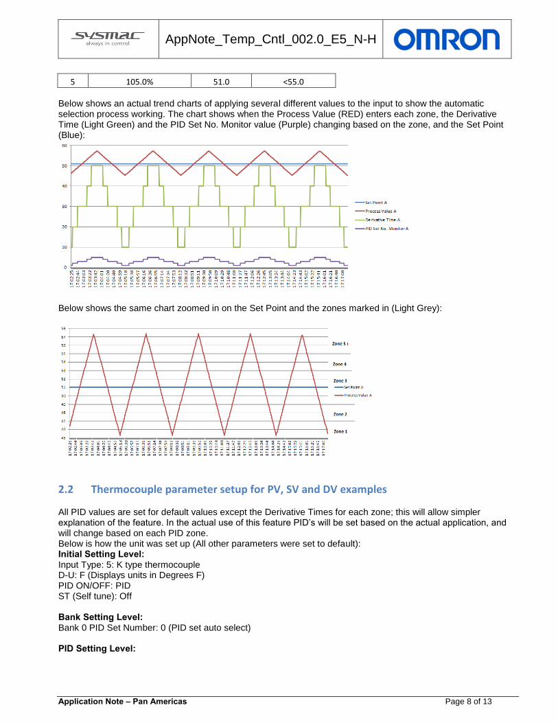
5 105.0% 51.0 <55.0 Below shows an actual trend charts of applying several different values to the input to show the automatic selection process working. The chart shows when the Process Value (RED) enters each zone, the Derivative Time (Light Green) and the PID Set No. Monitor value (Purple) changing based on the zone, and the Set Point (Blue):
Below shows the same chart zoomed in on the Set Point and the zones marked in (Light Grey):
2.2 Thermocouple parameter setup for PV, SV and DV examples All PID values are set for default values except the Derivative Times for each zone; this will allow simpler explanation of the feature. In the actual use of this feature PID’s will be set based on the actual application, and will change based on each PID zone. Below is how the unit was set up (All other parameters were set to default): Initial Setting Level: Input Type: 5: K type thermocouple D-U: F (Displays units in Degrees F) PID ON/OFF: PID ST (Self tune): Off Bank Setting Level: Bank 0 PID Set Number: 0 (PID set auto select) PID Setting Level:

AppNote_Temp_Cntl_002.0_E5_N-H
Application Note – Pan Americas Page 9 of 13
Below are the settings to set up the zones for the application. We will set up a total of 5 zones. Since 5 zones are required PID Automatic Selection Range Upper Limit 5 to 8 will be left at default. The unit will then only go up to zone 5 and use the PID values in zone 5 regardless of the PID in zone 6 through 8:
PV and SV DV Examples: Example: PID 1 Automatic Selection Range Upper Limit: 50.0° F -50° F PID 2 Automatic Selection Range Upper Limit: 70.0° F -25° F PID 3 Automatic Selection Range Upper Limit: 90.0° F 25° F PID 4 Automatic Selection Range Upper Limit: 110.0° F 50° F PID 5 Automatic Selection Range Upper Limit: 2340.0° F 2340.0° F PID 6 Automatic Selection Range Upper Limit: 2340.0° F 2340.0° F PID 7 Automatic Selection Range Upper Limit: 2340.0° F 2340.0° F PID 8 Automatic Selection Range Upper Limit: 2340.0° F 2340.0° F
To show the Derivative Time changing when the Process Value enters each zone, each Derivative Time 1 – 5 will have its own unique value. Since we only need 5 zones the PID values for 6 through 8 will be left at default:
PV and SV DV Examples: Example:
1.D PID 1 Derivative Time: 10.0 sec. 10.0 sec. 2.D PID 2 Derivative Time: 20.0 sec. 20.0 sec. 3.D PID 3 Derivative Time: 30.0 sec. 30.0 sec. 4.D PID 4 Derivative Time: 40.0 sec. 40.0 sec. 5.D PID 5 Derivative Time: 50.0 sec. 50.0 sec. 6.D PID 6 Derivative Time: 40.0 sec. 40.0 sec. 7.D PID 7 Derivative Time: 40.0 sec. 40.0 sec. 8.D PID 8 Derivative Time: 40.0 sec. 40.0 sec. Advanced Function Level: PID Set Automatic Selection Data: PV, SV or DV PID Set Automatic Selection Hysteresis: 0.50% (Based on Full Scale of input range)
2.2.1 Application 4: Thermocouple input, Automatic Selection Data: Process Value
This application is to show how the unit works with a Thermocouple input using an Automatic PID selection. The PID Set Automatic Selection Data will be based on the process value. For this application only 5 zones will be used. In this application it is set up having a thermocouple as an input. So the zone will be based on actual temperature.
The graph below shows the relation of the Process Value to zone selection:
Zone Automatic Selection Range Upper Limit PV Displayed Value
1 50.0° F <50.0° F
2 70.0° F 50.0 – 70.0° F
3 90.0° F 70.0 – 90.0° F
4 110.0° F 90.0 –110.0° F
5 2340.0° F 110.0- 2340.0° F

AppNote_Temp_Cntl_002.0_E5_N-H
Application Note – Pan Americas Page 10 of 13
Since the PID Set Automatic Selection Hysteresis is set to 0.50% (Full Scale), below is the calculation to determine actual degrees: K Type input has a full scale range of -300°F to 2300°F. Full scale value would then be -300°F + 2300°F = 2600°F, So 2600°F x 0.50% = 13°F. Below shows an actual trend chart of applying several different temperatures to the input to show the automatic selection process working. The chart Shows when the Process Value (RED) enters each zone the Derivative Time (Light Green) changes as well as the PID Set No. Monitor value (Purple), based on the zone requirements:
Note: In the above graph a portion of the graph is circled to show how the hysteresis value has a part in the PID Automatic Selection Function. Even though the temperature is within zone 1 (50°F) it still has not reached the hysteresis level. Once the process value reaches 37°F or less the process will fall into zone 1.
2.2.2 Application 5: Thermocouple input, Automatic Selection Data: Set Point
Using the Set Point as the automatic selection data is very similar to using the Process Value. When using the Set Value the PID zone will be based on the set point rather than the Process Value. In the applications above the set point was always set to 0. So it was purely based on the Process Value for the zone determination. When using the Set Point it would be based on the Set Point. Trial and error is the best to determine which is better for the application. The chart below shows the Set value range for each zone in this application:
Zone Automatic Selection Range Upper Limit SV Zone Value
1 50.0° F <50.0° F
2 70.0° F 50.0 - 70.0° F
3 90.0° F 70.0 - 90.0° F
4 110.0° F 90.0 - 110.0° F
5 2340.0° F 110.0° F >
AppNote_Temp_Cntl_002.0_E5_N-H
Application Note – Pan Americas Page 11 of 13
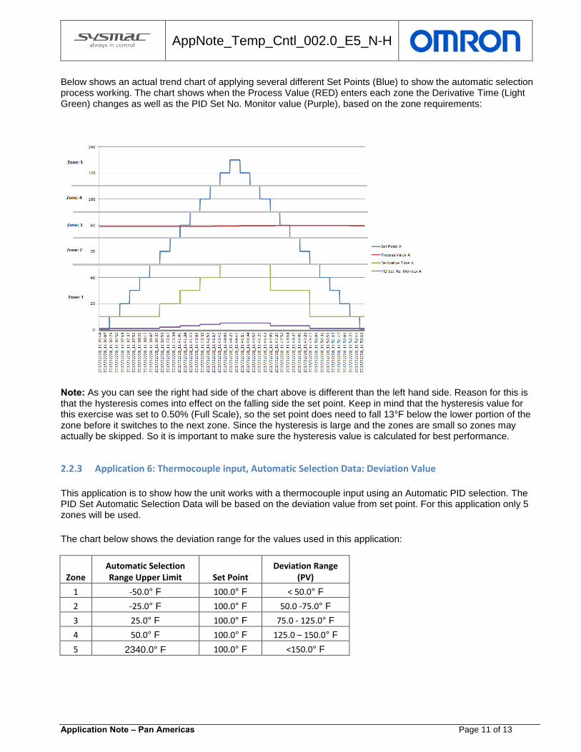
Below shows an actual trend chart of applying several different Set Points (Blue) to show the automatic selection process working. The chart shows when the Process Value (RED) enters each zone the Derivative Time (Light Green) changes as well as the PID Set No. Monitor value (Purple), based on the zone requirements:
Note: As you can see the right had side of the chart above is different than the left hand side. Reason for this is that the hysteresis comes into effect on the falling side the set point. Keep in mind that the hysteresis value for this exercise was set to 0.50% (Full Scale), so the set point does need to fall 13°F below the lower portion of the zone before it switches to the next zone. Since the hysteresis is large and the zones are small so zones may actually be skipped. So it is important to make sure the hysteresis value is calculated for best performance.
2.2.3 Application 6: Thermocouple input, Automatic Selection Data: Deviation Value
This application is to show how the unit works with a thermocouple input using an Automatic PID selection. The PID Set Automatic Selection Data will be based on the deviation value from set point. For this application only 5 zones will be used.
The chart below shows the deviation range for the values used in this application:
Zone Automatic Selection Range Upper Limit Set Point
Deviation Range (PV)
1 -50.0° F 100.0° F < 50.0° F
2 -25.0° F 100.0° F 50.0 -75.0° F
3 25.0° F 100.0° F 75.0 - 125.0° F
4 50.0° F 100.0° F 125.0 – 150.0° F
5 2340.0° F 100.0° F <150.0° F

AppNote_Temp_Cntl_002.0_E5_N-H
Application Note – Pan Americas Page 12 of 13
Since the PID Set Automatic Selection Hysteresis is set to 0.50% (Full Scale), below is the calculation to determine actual degrees: K Type input has a full scale range of -300°F to 2300°F. Full scale value would then be -300°F + 2300°F = 2600°F, So 2600°F x 0.50% = 13°F. The chart below shows how the hysteresis value (dashed lines) reacts in relation to the deviation range:
Below shows an actual trend charts of applying several different values to the input to show the automatic selection process working. The chart shows when the Process Value (RED) enters each zone, the Derivative Time (Light Green) and the PID Set No. Monitor value (Purple) changing based on the zone, and the Set Point (Blue):
Note: In the above graph a portion of the graph is circled to show how the hysteresis value has a part in the PID Automatic Selection Function. Even though the temperature is within zone 2 (68°F) it still has not reached the hysteresis level. Once the process value reaches 61°F or less the process will fall into zone 2.

AppNote_Temp_Cntl_002.0_E5_N-H
Application Note – Pan Americas Page 13 of 13
Useful tools: CX-Thermo: PID Set No. Monitor can be used when trending to indicate the PID set that is being used based on the present Automatic Selection Data selection. d.PId screen on the unit will also display the PID set that is being used based on the present Automatic Selection Data selection.

OMRON CANADA, INC. • HEAD OFFICEToronto, ON, Canada • 416.286.6465 • 866.986.6766 • www.omron247.com
OMRON ELECTRONICS DE MEXICO • HEAD OFFICEMéxico DF • 52.55.59.01.43.00 • 01-800-226-6766 • [email protected]
OMRON ELECTRONICS DE MEXICO • SALES OFFICEApodaca, N.L. • 52.81.11.56.99.20 • 01-800-226-6766 • [email protected]
OMRON ELETRÔNICA DO BRASIL LTDA • HEAD OFFICESão Paulo, SP, Brasil • 55.11.2101.6300 • www.omron.com.br
OMRON ARGENTINA • SALES OFFICECono Sur • 54.11.4783.5300
OMRON CHILE • SALES OFFICESantiago • 56.9.9917.3920
OTHER OMRON LATIN AMERICA SALES54.11.4783.5300
Authorized Distributor:
H53I-E-01 06/17 Note: Specifications are subject to change. © 2017 Omron. All Rights Reserved. Printed in U.S.A.
Printed on recycled paper.
OMRON AUTOMATION AMERICAS HEADQUARTERS • Chicago, IL USA • 847.843.7900 • 800.556.6766 • www.omron247.com
OMRON EUROPE B.V. • Wegalaan 67-69, NL-2132 JD, Hoofddorp, The Netherlands. • +31 (0) 23 568 13 00 • www.industrial.omron.eu
Controllers & I/O • Machine Automation Controllers (MAC) • Motion Controllers • Programmable Logic Controllers (PLC) • Temperature Controllers • Remote I/O
Robotics • Industrial Robots • Mobile Robots
Operator Interfaces• Human Machine Interface (HMI)
Motion & Drives• Machine Automation Controllers (MAC) • Motion Controllers • Servo Systems • Frequency Inverters
Vision, Measurement & Identification• Vision Sensors & Systems • Measurement Sensors • Auto Identification Systems
Sensing• Photoelectric Sensors • Fiber-Optic Sensors • Proximity Sensors • Rotary Encoders • Ultrasonic Sensors
Safety • Safety Light Curtains • Safety Laser Scanners • Programmable Safety Systems • Safety Mats and Edges • Safety Door Switches • Emergency Stop Devices • Safety Switches & Operator Controls • Safety Monitoring/Force-guided Relays
Control Components • Power Supplies • Timers • Counters • Programmable Relays • Digital Panel Meters • Monitoring Products
Switches & Relays • Limit Switches • Pushbutton Switches • Electromechanical Relays • Solid State Relays
Software • Programming & Configuration • Runtime