Embed Size (px)
Citation preview

Cat. No. I576-E1-01
USER’S MANUAL
OMNUC G5 SERIES
R88M-K@(AC Servomotors)
R88D-KN@-ECT(AC Servo Drives)
AC SERVOMOTORS/SERVO DRIVESWITH BUILT-IN EtherCAT COMMUNICATIONS
Trademarks and Copyrights
•
OMRON, 2010All rights reserved. No part of this publication may be reproduced, stored in a retrieval system, or transmitted, in anyform, or by any means, mechanical, electronic, photocopying, recording, or otherwise, without the prior written permis-sion of OMRON.
No patent liability is assumed with respect to the use of the information contained herein. Moreover, because OMRON isconstantly striving to improve its high-quality products, the information contained in this manual is subject to changewithout notice. Every precaution has been taken in the preparation of this manual. Nevertheless, OMRON assumes noresponsibility for errors or omissions. Neither is any liability assumed for damages resulting from the use of the informa-tion contained in this publication.
EtherCAT is a registered trademark of Beckhoff Automation Gmbh (Germany). EtherCAT technology is protected by patents.Other system names and product names that appear in this manual are the trademarks or registered trademarks of the relevant companies.
•
Introduction
IntroductionThank you for purchasing an OMNUC G5-series Servo Drive. This manual explains how to installand wire the Servo Drive, set parameters needed to operate the Servo Drive, and remedies to betaken and inspection methods to be used should problems occur.
Intended ReadersThis manual is intended for the following individuals.
Those having electrical knowledge (certified electricians or individuals having equivalent knowledge) and also being qualified for one of the following:• Introducing FA equipment• Designing FA systems• Managing FA sites
NoticeThis manual contains information you need to know to correctly use the Servo Drive and peripheralequipment. Before using the Servo Drive, read this manual and gain a full understanding of theinformation provided herein.After you finished reading this manual, keep it in a convenient place so that it can be referenced atany time.Make sure this manual is delivered to the end user.
1OMNUC G5-series AC Servomotors and Servo Drives User’s Manual (with Built-in EtherCAT Communications)
Read and Understand this Manual
Read and Understand this Manual
Warranty and Limitations of LiabilityWARRANTY
OMRON's exclusive warranty is that the products are free from defects in materials and workmanship for a period of one year (or other period if specified) from date of sale by OMRON.
OMRON MAKES NO WARRANTY OR REPRESENTATION, EXPRESS OR IMPLIED, REGARDING NONINFRINGEMENT, MERCHANTABILITY, OR FITNESS FOR PARTICULAR PURPOSE OF THE PRODUCTS. ANY BUYER OR USER ACKNOWLEDGES THAT THE BUYER OR USER ALONE HAS DETERMINED THAT THE PRODUCTS WILL SUITABLY MEET THE REQUIREMENTS OF THEIR INTENDED USE. OMRON DISCLAIMS ALL OTHER WARRANTIES, EXPRESS OR IMPLIED.
LIMITATIONS OF LIABILITYOMRON SHALL NOT BE RESPONSIBLE FOR SPECIAL, INDIRECT, OR CONSEQUENTIAL DAMAGES, LOSS OF PROFITS OR COMMERCIAL LOSS IN ANY WAY CONNECTED WITH THE PRODUCTS, WHETHER SUCH CLAIM IS BASED ON CONTRACT, WARRANTY, NEGLIGENCE, OR STRICT LIABILITY.
In no event shall the responsibility of OMRON for any act exceed the individual price of the product on which liability is asserted.
IN NO EVENT SHALL OMRON BE RESPONSIBLE FOR WARRANTY, REPAIR, OR OTHER CLAIMS REGARDING THE PRODUCTS UNLESS OMRON'S ANALYSIS CONFIRMS THAT THE PRODUCTS WERE PROPERLY HANDLED, STORED, INSTALLED, AND MAINTAINED AND NOT SUBJECT TO CONTAMINATION, ABUSE, MISUSE, OR INAPPROPRIATE MODIFICATION OR REPAIR.
2 OMNUC G5-series AC Servomotors and Servo Drives User’s Manual (with Built-in EtherCAT Communications)
Read and Understand this Manual
Application ConsiderationsSUITABILITY FOR USE
OMRON shall not be responsible for conformity with any standards, codes, or regulations that apply to the combination of products in the customer's application or use of the products.
At the customer's request, OMRON will provide applicable third party certification documents identifying ratings and limitations of use that apply to the products. This information by itself is not sufficient for a complete determination of the suitability of the products in combination with the end product, machine, system, or other application or use.
The following are some examples of applications for which particular attention must be given. This is not intended to be an exhaustive list of all possible uses of the products, nor is it intended to imply that the uses listed may be suitable for the products:
• Outdoor use, uses involving potential chemical contamination or electrical interference, or conditions or usesnot described in this manual.
• Nuclear energy control systems, combustion systems, railroad systems, aviation systems, medicalequipment, amusement machines, vehicles, safety equipment, and installations subject to separate industryor government regulations.
• Systems, machines, and equipment that could present a risk to life or property. Please know and observe allprohibitions of use applicable to the products.
NEVER USE THE PRODUCTS FOR AN APPLICATION INVOLVING SERIOUS RISK TO LIFE OR PROPERTY WITHOUT ENSURING THAT THE SYSTEM AS A WHOLE HAS BEEN DESIGNED TO ADDRESS THE RISKS, AND THAT THE OMRON PRODUCTS ARE PROPERLY RATED AND INSTALLED FOR THE INTENDED USE WITHIN THE OVERALL EQUIPMENT OR SYSTEM.
PROGRAMMABLE PRODUCTSOMRON shall not be responsible for the user's programming of a programmable product, or any consequence thereof.
3OMNUC G5-series AC Servomotors and Servo Drives User’s Manual (with Built-in EtherCAT Communications)
Read and Understand this Manual
DisclaimersCHANGE IN SPECIFICATIONS
Product specifications and accessories may be changed at any time based on improvements and other reasons. It is our practice to change model numbers when published ratings or features are changed, or when significant construction changes are made. However, some specifications of the products may be changed without any notice. When in doubt, special model numbers may be assigned to fix or establish key specifications for your application on your request. Please consult with your OMRON representative at any time to confirm actual specifications of purchased products.
DIMENSIONS AND WEIGHTSDimensions and weights are nominal and are not to be used for manufacturing purposes, even when tolerances are shown.
PERFORMANCE DATAPerformance data given in this manual is provided as a guide for the user in determining suitability and does not constitute a warranty. It may represent the result of OMRON's test conditions, and the users must correlate it to actual application requirements. Actual performance is subject to the OMRON Warranty and Limitations of Liability.
ERRORS AND OMISSIONSThe information in this manual has been carefully checked and is believed to be accurate; however, no responsibility is assumed for clerical, typographical, or proofreading errors, or omissions.
4 OMNUC G5-series AC Servomotors and Servo Drives User’s Manual (with Built-in EtherCAT Communications)
Safety Precautions
Safety PrecautionsTo ensure that the OMNUC G5-series Servomotor and Servo Drive as well as peripheral equipment are usedsafely and correctly, be sure to read this Safety Precautions section and the main text before using the productin order to learn items you should know regarding the equipment as well as required safety information andprecautions.Make an arrangement so that this manual also gets to the end user of this product.After reading this manual, keep it in a convenient place so that it can be referenced at any time.
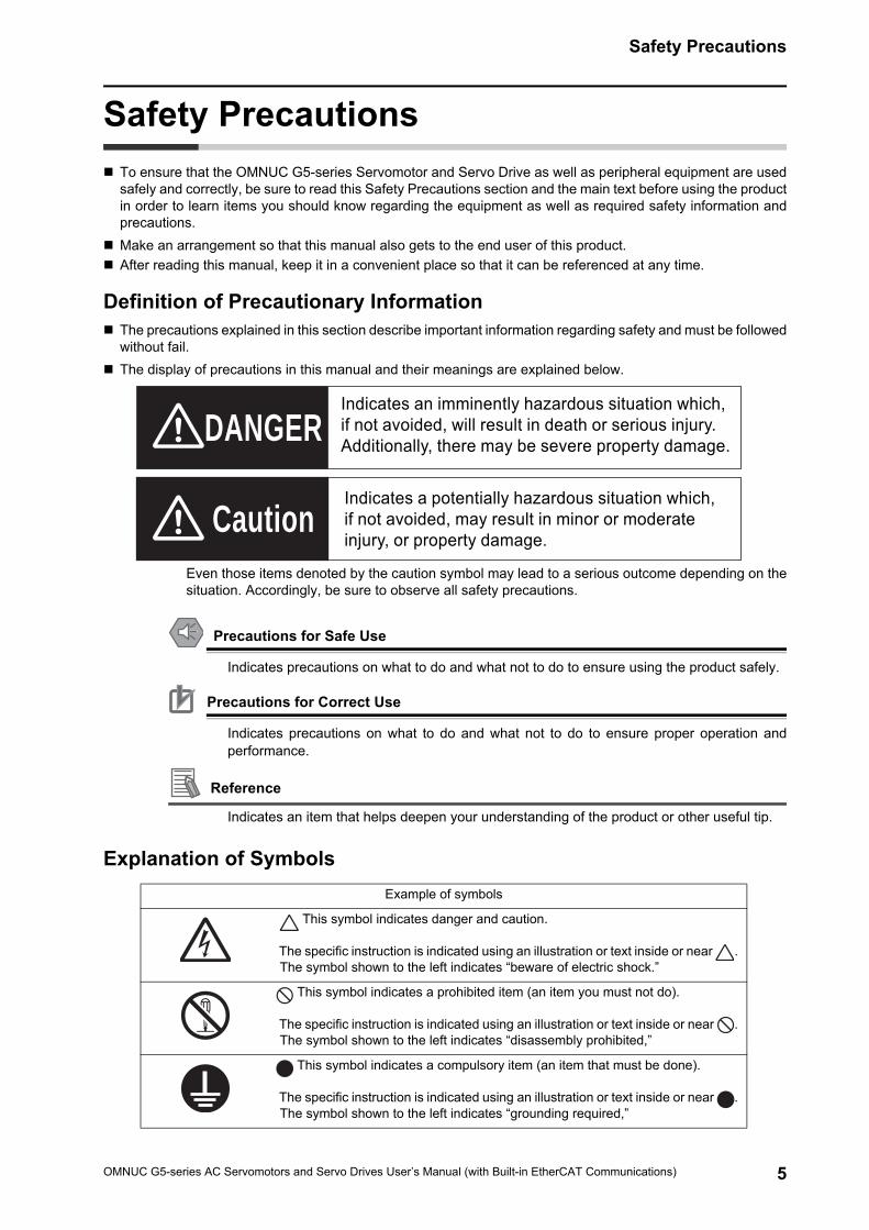
Definition of Precautionary InformationThe precautions explained in this section describe important information regarding safety and must be followedwithout fail.The display of precautions in this manual and their meanings are explained below.
Even those items denoted by the caution symbol may lead to a serious outcome depending on thesituation. Accordingly, be sure to observe all safety precautions.
Precautions for Safe Use
Indicates precautions on what to do and what not to do to ensure using the product safely.
Precautions for Correct Use
Indicates precautions on what to do and what not to do to ensure proper operation andperformance.
Reference
Indicates an item that helps deepen your understanding of the product or other useful tip.
Explanation of SymbolsExample of symbols
This symbol indicates danger and caution.
The specific instruction is indicated using an illustration or text inside or near . The symbol shown to the left indicates “beware of electric shock.”
This symbol indicates a prohibited item (an item you must not do).
The specific instruction is indicated using an illustration or text inside or near . The symbol shown to the left indicates “disassembly prohibited,”
This symbol indicates a compulsory item (an item that must be done).
The specific instruction is indicated using an illustration or text inside or near . The symbol shown to the left indicates “grounding required,”
DANGER
Caution
Indicates an imminently hazardous situation which, if not avoided, will result in death or serious injury. Additionally, there may be severe property damage.
Indicates a potentially hazardous situation which, if not avoided, may result in minor or moderate injury, or property damage.
5OMNUC G5-series AC Servomotors and Servo Drives User’s Manual (with Built-in EtherCAT Communications)
Safety Precautions
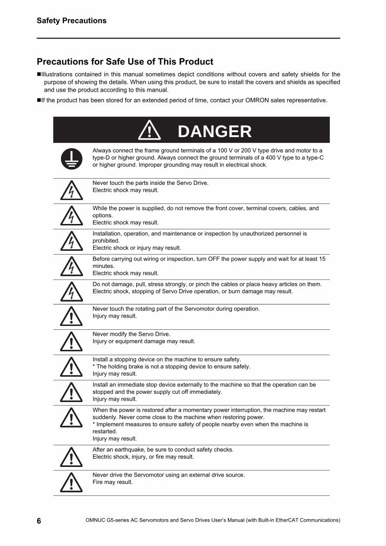
Precautions for Safe Use of This ProductIllustrations contained in this manual sometimes depict conditions without covers and safety shields for thepurpose of showing the details. When using this product, be sure to install the covers and shields as specifiedand use the product according to this manual.
If the product has been stored for an extended period of time, contact your OMRON sales representative.
Always connect the frame ground terminals of a 100 V or 200 V type drive and motor to a type-D or higher ground. Always connect the ground terminals of a 400 V type to a type-C or higher ground. Improper grounding may result in electrical shock.
Never touch the parts inside the Servo Drive.Electric shock may result.
While the power is supplied, do not remove the front cover, terminal covers, cables, and options.Electric shock may result.
Installation, operation, and maintenance or inspection by unauthorized personnel is prohibited.Electric shock or injury may result.
Before carrying out wiring or inspection, turn OFF the power supply and wait for at least 15 minutes.Electric shock may result.
Do not damage, pull, stress strongly, or pinch the cables or place heavy articles on them.Electric shock, stopping of Servo Drive operation, or burn damage may result.
Never touch the rotating part of the Servomotor during operation.Injury may result.
Never modify the Servo Drive.Injury or equipment damage may result.
Install a stopping device on the machine to ensure safety.* The holding brake is not a stopping device to ensure safety.Injury may result.
Install an immediate stop device externally to the machine so that the operation can be stopped and the power supply cut off immediately.Injury may result.
When the power is restored after a momentary power interruption, the machine may restart suddenly. Never come close to the machine when restoring power.* Implement measures to ensure safety of people nearby even when the machine is restarted.Injury may result.
After an earthquake, be sure to conduct safety checks.Electric shock, injury, or fire may result.
Never drive the Servomotor using an external drive source.Fire may result.
DANGER
6 OMNUC G5-series AC Servomotors and Servo Drives User’s Manual (with Built-in EtherCAT Communications)
Safety Precautions
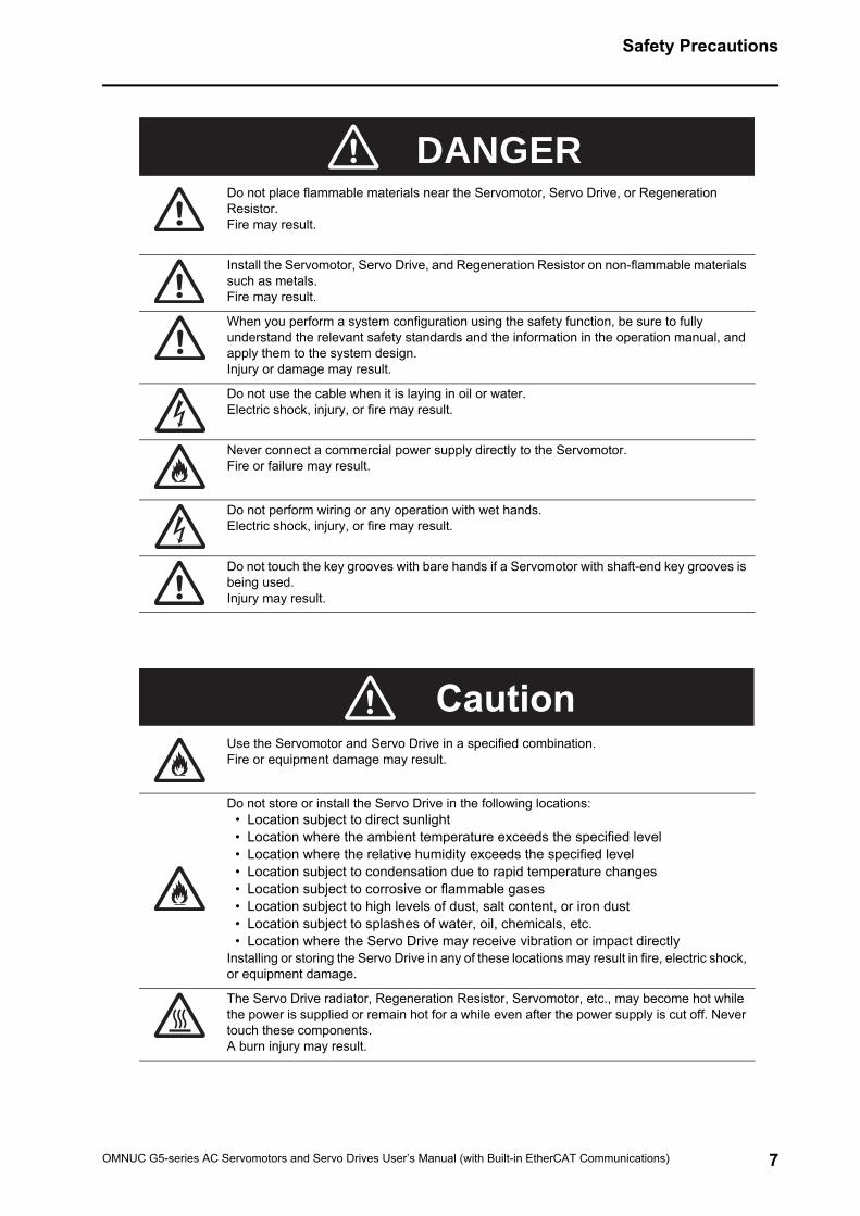
Do not place flammable materials near the Servomotor, Servo Drive, or Regeneration Resistor.Fire may result.
Install the Servomotor, Servo Drive, and Regeneration Resistor on non-flammable materials such as metals.Fire may result.
When you perform a system configuration using the safety function, be sure to fully understand the relevant safety standards and the information in the operation manual, and apply them to the system design.Injury or damage may result.
Do not use the cable when it is laying in oil or water.Electric shock, injury, or fire may result.
Never connect a commercial power supply directly to the Servomotor.Fire or failure may result.
Do not perform wiring or any operation with wet hands.Electric shock, injury, or fire may result.
Do not touch the key grooves with bare hands if a Servomotor with shaft-end key grooves is being used.Injury may result.
Use the Servomotor and Servo Drive in a specified combination.Fire or equipment damage may result.
Do not store or install the Servo Drive in the following locations:• Location subject to direct sunlight• Location where the ambient temperature exceeds the specified level• Location where the relative humidity exceeds the specified level• Location subject to condensation due to rapid temperature changes• Location subject to corrosive or flammable gases• Location subject to high levels of dust, salt content, or iron dust• Location subject to splashes of water, oil, chemicals, etc.• Location where the Servo Drive may receive vibration or impact directly
Installing or storing the Servo Drive in any of these locations may result in fire, electric shock, or equipment damage.
The Servo Drive radiator, Regeneration Resistor, Servomotor, etc., may become hot while the power is supplied or remain hot for a while even after the power supply is cut off. Never touch these components.A burn injury may result.
DANGER
Caution
7OMNUC G5-series AC Servomotors and Servo Drives User’s Manual (with Built-in EtherCAT Communications)
Safety Precautions
Storage and Transportation
When transporting the Servo Drive, do not hold it by the cables or Servomotor shaft.Injury or failure may result.
Do not overload the Servo Drive or Servomotor. (Follow the instructions on the product label.) Injury or failure may result.
Use the Servomotor eye-bolts only when transporting the Servomotor.Do not use them to transport the machine.Injury or failure may result.
When lifting a 15 kW or higher Servo Drive during moving or installation, always have two people lift the product by grasping a metal part. Do not grasp a plastic part.Risk of injury or product damage.
Caution
8 OMNUC G5-series AC Servomotors and Servo Drives User’s Manual (with Built-in EtherCAT Communications)
Safety Precautions
Installation and Wiring
Do not step on the Servo Drive or place heavy articles on it.Injury may result.
Do not block the intake or exhaust openings. Do not allow foreign objects to enter the Servo Drive.Fire may result.
Be sure to observe the mounting direction.Failure may result.
Provide the specified clearance between the Servo Drive and the inner surface of the control panel or other equipment.Fire or failure may result.
Do not apply strong impact on the Servomotor shaft or Servo Drive.Failure may result.
Wire the cables correctly and securely.Runaway Servomotor, injury, or failure may result.
Securely tighten the mounting screws, terminal block screws, and cable screws.Failure may result.
Use crimp terminals for wiring.If simple twisted wires are connected directly to the protective ground terminal, fire may result.
Only use the power supply voltage specified in this manual.Burn damage may result.
In locations where the power supply infrastructure is poor, make sure the rated voltage can be supplied.Equipment damage may result.
Provide safety measures, such as a breaker, to protect against short circuiting of external wiring.Fire may result.
If the Servo Drive is used in the following locations, provide sufficient shielding measures.• Location subject to noise e.g., due to static electricity• Location subject to a strong electric or magnetic field• Location where exposure to radioactivity may occur• Location near power supply lines
Using the Servo Drive in any of these locations may result in equipment damage.
Connect an immediate stop relay in series with the brake control relay.Injury or failure may result.
When connecting the battery, make sure the polarity is correct.Battery damage or explosion may result.
Caution
9OMNUC G5-series AC Servomotors and Servo Drives User’s Manual (with Built-in EtherCAT Communications)
Safety Precautions
Operation and Adjustment
Maintenance and Inspection
Conduct a test operation after confirming that the equipment is not affected.Equipment damage may result.
Before operating the Servo Drive in an actual environment, check if it operates correctly based on the parameters you have set.Equipment damage may result.
Never adjust or set parameters to extreme values, because it will make the operation unstable.Injury may result.
Separate the Servomotor from the mechanical system and check its operation before installing the Servomotor to the machine.Injury may result.
If an error occurs, remove the cause of the error and ensure safety, and then reset the alarm and restart the operation.Injury may result.
Do not use the built-in brake of the Servomotor for normal braking operation.Failure may result.
Do not operate the Servomotor connected to an excessive load inertia.Failure may result.
Install safety devices to prevent idling or locking of the electromagnetic brake or the gear head, or leakage of grease from the gear head.Injury, damage, or taint damage result.
If the Servo Drive fails, cut off the power supply to the Servo Drive at the power supply.Fire may result.
Do not turn ON and OFF the main Servo Drive power supply frequently.Failure may result.
After replacing the Servo Drive, transfer to the new Servo Drive all data needed to resume operation, before restarting operation.Equipment damage may result.
Never repair the Servo Drive by disassembling it.Electric shock or injury may result.
Be sure to turn OFF the power supply when the Servo Drive is not going to be used for a prolonged period of time.Injury may result.
Caution
Caution
10 OMNUC G5-series AC Servomotors and Servo Drives User’s Manual (with Built-in EtherCAT Communications)
Safety Precautions
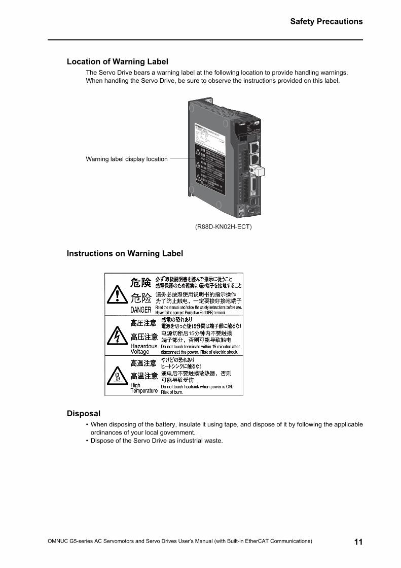
Location of Warning LabelThe Servo Drive bears a warning label at the following location to provide handling warnings.When handling the Servo Drive, be sure to observe the instructions provided on this label.
Instructions on Warning Label
Disposal• When disposing of the battery, insulate it using tape, and dispose of it by following the applicable
ordinances of your local government.• Dispose of the Servo Drive as industrial waste.
Warning label display location
(R88D-KN02H-ECT)
VOLTAGE 100~120V1Ø
3Ø0-120V
INPUTOUTPUT
PHASE
2.6A50/60Hz
0~500.0Hz
1.7A
100WA09080004
FREQPOWER
OMRON Corporation
MADE IN JAPAN
SERIAL No.
F L C
11OMNUC G5-series AC Servomotors and Servo Drives User’s Manual (with Built-in EtherCAT Communications)
Items to Check after Unpacking
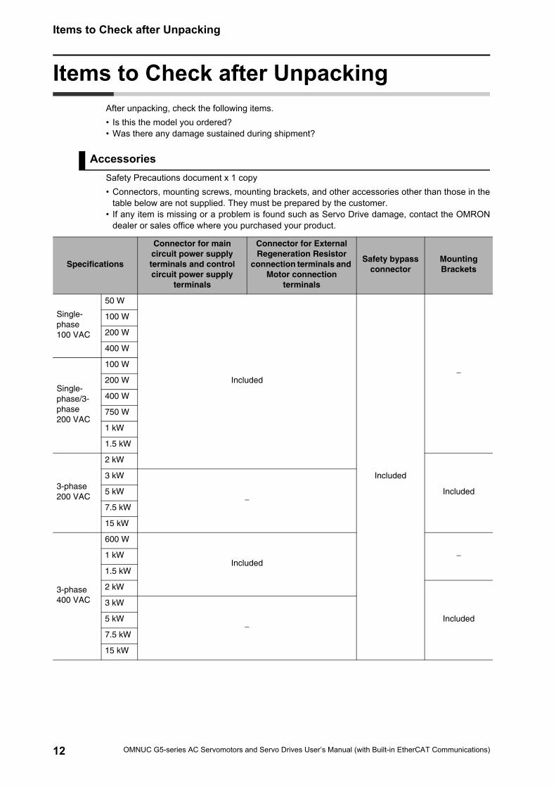
Items to Check after UnpackingAfter unpacking, check the following items.• Is this the model you ordered?• Was there any damage sustained during shipment?
AccessoriesSafety Precautions document x 1 copy• Connectors, mounting screws, mounting brackets, and other accessories other than those in the
table below are not supplied. They must be prepared by the customer.• If any item is missing or a problem is found such as Servo Drive damage, contact the OMRON
dealer or sales office where you purchased your product.
Specifications
Connector for main circuit power supply terminals and control circuit power supply
terminals
Connector for External Regeneration Resistor
connection terminals and Motor connection
terminals
Safety bypass connector
Mounting Brackets
Single-phase 100 VAC
50 W
Included
Included
−
100 W
200 W
400 W
Single-phase/3-phase 200 VAC
100 W
200 W
400 W
750 W
1 kW
1.5 kW
3-phase 200 VAC
2 kW
Included
3 kW
−5 kW
7.5 kW
15 kW
3-phase 400 VAC
600 W
Included−1 kW
1.5 kW
2 kW
Included
3 kW
−5 kW
7.5 kW
15 kW
12 OMNUC G5-series AC Servomotors and Servo Drives User’s Manual (with Built-in EtherCAT Communications)
Revision History
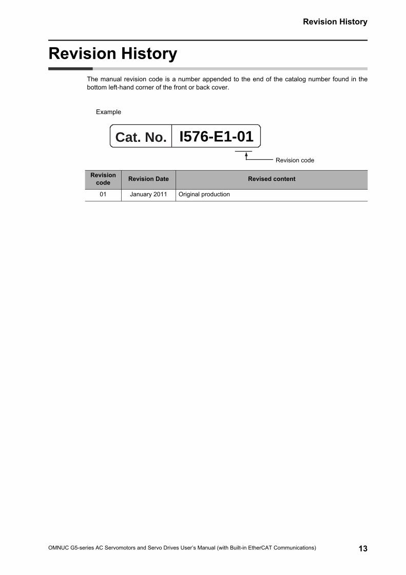
Revision HistoryThe manual revision code is a number appended to the end of the catalog number found in thebottom left-hand corner of the front or back cover.
Example
Revision code Revision Date Revised content
01 January 2011 Original production
I576-E1-01Revision code
Cat. No.
13OMNUC G5-series AC Servomotors and Servo Drives User’s Manual (with Built-in EtherCAT Communications)
Structure of This Document
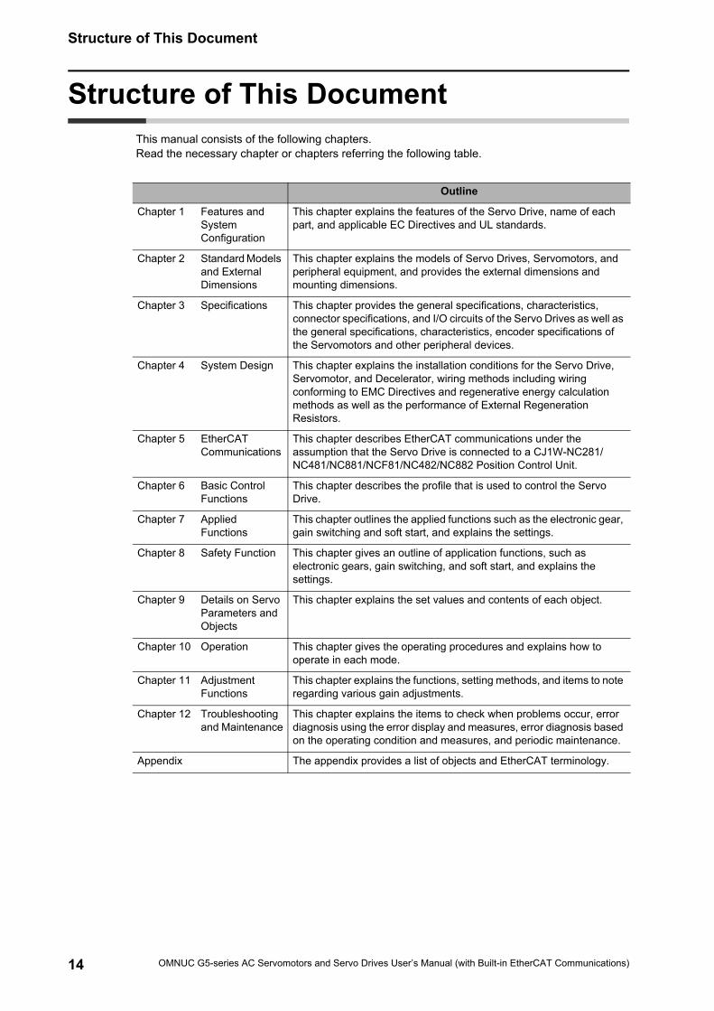
Structure of This DocumentThis manual consists of the following chapters.Read the necessary chapter or chapters referring the following table.
Outline
Chapter 1 Features and System Configuration
This chapter explains the features of the Servo Drive, name of each part, and applicable EC Directives and UL standards.
Chapter 2 Standard Models and External Dimensions
This chapter explains the models of Servo Drives, Servomotors, and peripheral equipment, and provides the external dimensions and mounting dimensions.
Chapter 3 Specifications This chapter provides the general specifications, characteristics, connector specifications, and I/O circuits of the Servo Drives as well as the general specifications, characteristics, encoder specifications of the Servomotors and other peripheral devices.
Chapter 4 System Design This chapter explains the installation conditions for the Servo Drive, Servomotor, and Decelerator, wiring methods including wiring conforming to EMC Directives and regenerative energy calculation methods as well as the performance of External Regeneration Resistors.
Chapter 5 EtherCAT Communications
This chapter describes EtherCAT communications under the assumption that the Servo Drive is connected to a CJ1W-NC281/NC481/NC881/NCF81/NC482/NC882 Position Control Unit.
Chapter 6 Basic Control Functions
This chapter describes the profile that is used to control the Servo Drive.
Chapter 7 Applied Functions
This chapter outlines the applied functions such as the electronic gear, gain switching and soft start, and explains the settings.
Chapter 8 Safety Function This chapter gives an outline of application functions, such as electronic gears, gain switching, and soft start, and explains the settings.
Chapter 9 Details on Servo Parameters and Objects
This chapter explains the set values and contents of each object.
Chapter 10 Operation This chapter gives the operating procedures and explains how to operate in each mode.
Chapter 11 Adjustment Functions
This chapter explains the functions, setting methods, and items to note regarding various gain adjustments.
Chapter 12 Troubleshooting and Maintenance
This chapter explains the items to check when problems occur, error diagnosis using the error display and measures, error diagnosis based on the operating condition and measures, and periodic maintenance.
Appendix The appendix provides a list of objects and EtherCAT terminology.
14 OMNUC G5-series AC Servomotors and Servo Drives User’s Manual (with Built-in EtherCAT Communications)

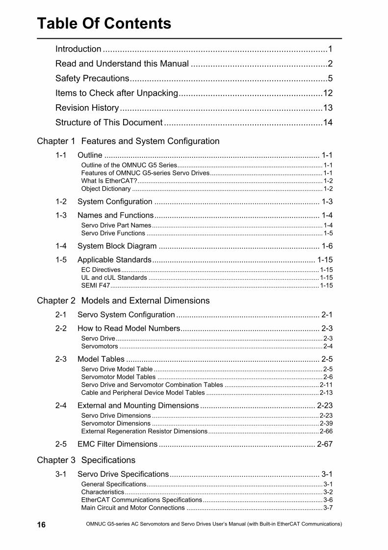
Table Of Contents
Introduction ............................................................................................1Read and Understand this Manual ........................................................2
Safety Precautions.................................................................................5
Items to Check after Unpacking...........................................................12
Revision History...................................................................................13
Structure of This Document .................................................................14
Chapter 1 Features and System Configuration1-1 Outline ................................................................................................... 1-1
Outline of the OMNUC G5 Series................................................................................1-1Features of OMNUC G5-series Servo Drives..............................................................1-1What Is EtherCAT?......................................................................................................1-2Object Dictionary .........................................................................................................1-2
1-2 System Configuration ............................................................................ 1-3
1-3 Names and Functions............................................................................ 1-4Servo Drive Part Names..............................................................................................1-4Servo Drive Functions .................................................................................................1-5
1-4 System Block Diagram .......................................................................... 1-6
1-5 Applicable Standards........................................................................... 1-15EC Directives............................................................................................................. 1-15UL and cUL Standards .............................................................................................. 1-15SEMI F47................................................................................................................... 1-15
Chapter 2 Models and External Dimensions2-1 Servo System Configuration .................................................................. 2-1
2-2 How to Read Model Numbers................................................................ 2-3Servo Drive.................................................................................................................. 2-3Servomotors ................................................................................................................2-4
2-3 Model Tables ......................................................................................... 2-5Servo Drive Model Table .............................................................................................2-5Servomotor Model Tables ...........................................................................................2-6Servo Drive and Servomotor Combination Tables .................................................... 2-11Cable and Peripheral Device Model Tables .............................................................. 2-13
2-4 External and Mounting Dimensions ..................................................... 2-23Servo Drive Dimensions ............................................................................................ 2-23Servomotor Dimensions ............................................................................................ 2-39External Regeneration Resistor Dimensions............................................................. 2-66
2-5 EMC Filter Dimensions ........................................................................ 2-67
Chapter 3 Specifications3-1 Servo Drive Specifications..................................................................... 3-1
General Specifications.................................................................................................3-1Characteristics.............................................................................................................3-2EtherCAT Communications Specifications..................................................................3-6Main Circuit and Motor Connections ...........................................................................3-7
16 OMNUC G5-series AC Servomotors and Servo Drives User’s Manual (with Built-in EtherCAT Communications)
Table Of Contents
EtherCAT Communications Connector Specifications (RJ45) .................................. 3-16Control I/O Connector Specifications (CN1).............................................................. 3-17Control Input Circuits ................................................................................................. 3-20Control Input Details .................................................................................................. 3-21Control Output Circuits .............................................................................................. 3-23Control Output Details ............................................................................................... 3-24Encoder Connector Specifications (CN2).................................................................. 3-28External Encoder Connector Specifications (CN4).................................................... 3-28Analog Monitor Connector Specifications (CN5) ....................................................... 3-32USB Connector Specifications (CN7)........................................................................ 3-33Safety Connector Specifications (CN8) ..................................................................... 3-34
3-2 Overload Characteristics (Electronic Thermal Function) ......................3-36Overload Characteristics Graphs .............................................................................. 3-36
3-3 Servomotor Specifications....................................................................3-37General Specifications............................................................................................... 3-37Characteristics........................................................................................................... 3-38Encoder Specifications .............................................................................................. 3-62
3-4 Cable and Connector Specifications ....................................................3-63Encoder Cable Specifications.................................................................................... 3-63Absolute Encoder Battery Cable Specifications ........................................................ 3-65Motor Power Cable Specifications............................................................................. 3-66Connector Specifications........................................................................................... 3-73EtherCAT Communications Cable Specifications ..................................................... 3-76Analog Monitor Cable Specifications......................................................................... 3-79Control Cable Specifications ..................................................................................... 3-81
3-5 External Regeneration Resistor Specifications ....................................3-86External Regeneration Resistor Specifications ......................................................... 3-86
3-6 EMC Filter Specifications .....................................................................3-88
Chapter 4 System Design4-1 Installation Conditions ............................................................................4-1
Servo Drive Installation Conditions.............................................................................. 4-1Servomotor Installation Conditions.............................................................................. 4-2Decelerator Installation Conditions.............................................................................. 4-5
4-2 Wiring .....................................................................................................4-6Peripheral Equipment Connection Examples .............................................................. 4-7Main Circuit and Motor Connections ......................................................................... 4-17
4-3 Wiring Conforming to EMC Directives ..................................................4-30Wiring Method ........................................................................................................... 4-30Selecting Connection Component ............................................................................. 4-38
4-4 Regenerative Energy Absorption..........................................................4-49Calculating the Regenerative Energy ........................................................................ 4-49Servo Drive Regeneration Absorption Capacity ........................................................ 4-51Regenerative Energy Absorption with an External Regeneration Resistor ............... 4-52Connecting an External Regeneration Resistor ........................................................ 4-53
Chapter 5 EtherCAT Communications5-1 Display Area and Settings ......................................................................5-1
Node Address Setting.................................................................................................. 5-1Status Indicators.......................................................................................................... 5-2
17OMNUC G5-series AC Servomotors and Servo Drives User’s Manual (with Built-in EtherCAT Communications)
Table Of Contents
5-2 Structure of the CAN Application Protocol over EtherCAT .................... 5-3
5-3 EtherCAT State Machine ....................................................................... 5-4
5-4 Process Data Objects (PDOs) ............................................................... 5-5PDO Mapping Settings ................................................................................................5-5Sync Manager PDO Assignment Settings...................................................................5-6Fixed PDO Mapping ....................................................................................................5-6
5-5 Service Data Objects (SDOs) ................................................................ 5-9Abort Codes.................................................................................................................5-9
5-6 Synchronization with Distributed Clocks.............................................. 5-10Communications Cycle (DC Cycle) ........................................................................... 5-10
5-7 Emergency Messages ......................................................................... 5-11
Chapter 6 Basic Control Functions6-1 Cyclic Synchronous Position Mode ....................................................... 6-1
Related Objects ...........................................................................................................6-2Block Diagram for Position Control Mode....................................................................6-3
6-2 Cyclic Synchronous Velocity Mode........................................................ 6-4Related Objects ...........................................................................................................6-5Objects Requiring Settings ..........................................................................................6-5Related Functions........................................................................................................6-5Block Diagram for Speed Control Mode ......................................................................6-6
6-3 Cyclic Synchronous Torque Mode......................................................... 6-7Related Objects ...........................................................................................................6-8Objects Requiring Settings ..........................................................................................6-8Related Functions........................................................................................................6-9Block Diagram for Torque Control Mode ................................................................... 6-10
6-4 Homing Mode ...................................................................................... 6-11
6-5 Fully-closed Control ............................................................................. 6-12Outline of Operation .................................................................................................. 6-12Objects Requiring Settings ........................................................................................ 6-13Block Diagram for Fully-closed Control Mode ........................................................... 6-18
6-6 Connecting with OMRON Controllers .................................................. 6-19Related Objects ......................................................................................................... 6-19
Chapter 7 Applied Functions7-1 Sequence I/O Signals ............................................................................ 7-1
Input Signals................................................................................................................7-1Output Signals .............................................................................................................7-4
7-2 Forward and Reverse Drive Prohibition Functions ................................ 7-6Objects Requiring Settings ..........................................................................................7-6
7-3 Overrun Protection................................................................................. 7-9Operating Conditions...................................................................................................7-9Objects Requiring Settings ..........................................................................................7-9Operation Example.................................................................................................... 7-10
7-4 Backlash Compensation ...................................................................... 7-11Objects Requiring Settings ........................................................................................ 7-11
18 OMNUC G5-series AC Servomotors and Servo Drives User’s Manual (with Built-in EtherCAT Communications)
Table Of Contents
7-5 Brake Interlock......................................................................................7-13Objects Requiring Settings........................................................................................ 7-13Operation Timing....................................................................................................... 7-14
7-6 Electronic Gear Function ......................................................................7-18Objects Requiring Settings........................................................................................ 7-18Operation Example.................................................................................................... 7-20
7-7 Torque Limit Switching .........................................................................7-21Operating Conditions................................................................................................. 7-21Objects Requiring Settings........................................................................................ 7-21
7-8 Soft Start...............................................................................................7-23Objects Requiring Settings........................................................................................ 7-23Soft Start Acceleration or Deceleration Time ............................................................ 7-23S-curve Acceleration or Deceleration Time............................................................... 7-24
7-9 Gain Switching Function.......................................................................7-25Objects Requiring Settings........................................................................................ 7-26Gain Switching Based on the Control Mode.............................................................. 7-27Diagrams of Gain Switching Setting .......................................................................... 7-32
7-10 Gain Switching 3 Function....................................................................7-35Operating Conditions................................................................................................. 7-35Objects Requiring Settings........................................................................................ 7-35Operation Example.................................................................................................... 7-36
7-11 Touch Probe Function (Latch Function) ...............................................7-37Related Objects ......................................................................................................... 7-37Trigger Signal Settings .............................................................................................. 7-37Operation Sequences................................................................................................ 7-38
Chapter 8 Safety Function8-1 Safe Torque OFF Function.....................................................................8-1
I/O Signal Specifications.............................................................................................. 8-2
8-2 Operation Example.................................................................................8-4
8-3 Connection Examples.............................................................................8-6
Chapter 9 Details on Servo Parameter Objects9-1 Basic Settings.........................................................................................9-1
9-2 Gain Settings ..........................................................................................9-7
9-3 Vibration Suppression Settings ............................................................9-20
9-4 Analog Control Objects.........................................................................9-26
9-5 Interface Monitor Settings.....................................................................9-31
9-6 Extended Objects .................................................................................9-40
9-7 Special Objects.....................................................................................9-47
Chapter 10Operation10-1 Operational Procedure .........................................................................10-1
10-2 Preparing for Operation ........................................................................10-2
19OMNUC G5-series AC Servomotors and Servo Drives User’s Manual (with Built-in EtherCAT Communications)
Table Of Contents
Items to Check Before Turning ON the Power Supply .............................................. 10-2Turning ON the Power Supply................................................................................... 10-3Checking the Displays ............................................................................................... 10-4Absolute Encoder Setup............................................................................................ 10-6Setting Up an Absolute Encoder from the CX-Drive.................................................. 10-6
10-3 Trial Operation ..................................................................................... 10-7Preparations for Trial Operation ................................................................................ 10-7Test Operation via USB Communications from the CX-Drive ................................... 10-8
Chapter 11Adjustment Functions11-1 Analog Monitor..................................................................................... 11-1
Objects Requiring Settings ........................................................................................ 11-1
11-2 Gain Adjustment .................................................................................. 11-4Purpose of the Gain Adjustment................................................................................ 11-4Gain Adjustment Methods ......................................................................................... 11-4Gain Adjustment Procedure ...................................................................................... 11-5
11-3 Realtime Autotuning ............................................................................ 11-6Objects Requiring Settings ........................................................................................ 11-7Setting Realtime Autotuning ...................................................................................... 11-7Setting Machine Rigidity ............................................................................................ 11-8
11-4 Manual Tuning ................................................................................... 11-13Basic Settings.......................................................................................................... 11-13
11-5 Damping Control................................................................................ 11-15Outline of Operation ................................................................................................ 11-15Objects Requiring Settings ...................................................................................... 11-15
11-6 Adaptive Filter.................................................................................... 11-18Objects Requiring Settings ...................................................................................... 11-19Operating Procedure ............................................................................................... 11-20
11-7 Notch Filters....................................................................................... 11-21Objects Requiring Settings ...................................................................................... 11-22
11-8 Disturbance Observer Function ......................................................... 11-24Operating Conditions............................................................................................... 11-24Objects Requiring Settings ...................................................................................... 11-25Operating Procedure ............................................................................................... 11-25
11-9 Friction Torque Compensation Function............................................ 11-26Operating Conditions............................................................................................... 11-26Objects Requiring Settings ...................................................................................... 11-26Operation Example.................................................................................................. 11-27
11-10 Hybrid Vibration Suppression Function ............................................ 11-28Operating Conditions............................................................................................... 11-28Objects Requiring Settings ...................................................................................... 11-28Operating Procedure ............................................................................................... 11-28
11-11 Feed-forward Function...................................................................... 11-29Objects Requiring Settings ...................................................................................... 11-29Operating Procedure ............................................................................................... 11-30
11-12 Instantaneous Speed Observer Function ......................................... 11-32Operating Conditions............................................................................................... 11-32
20 OMNUC G5-series AC Servomotors and Servo Drives User’s Manual (with Built-in EtherCAT Communications)
Table Of Contents
Objects Requiring Settings...................................................................................... 11-32Operating Procedure ............................................................................................... 11-33
Chapter 12Troubleshooting and Maintenance12-1 Troubleshooting....................................................................................12-1
Preliminary Checks When a Problem Occurs ........................................................... 12-1Precautions When a Problem Occurs ....................................................................... 12-2Replacing the Servomotor or Servo Drive ................................................................. 12-2
12-2 Warnings ..............................................................................................12-4Related Objects ......................................................................................................... 12-4Warning List............................................................................................................... 12-5
12-3 Errors....................................................................................................12-7Immediate Stop Operation at Errors........................................................................ 12-11
12-4 Troubleshooting..................................................................................12-13Troubleshooting with Error Displays........................................................................ 12-13Troubleshooting Using the Operation State ............................................................ 12-27
12-5 Periodic Maintenance .........................................................................12-33Servomotor Life Expectancy.................................................................................... 12-33Servo Drive Life Expectancy ................................................................................... 12-34Replacing the Absolute Encoder Battery ................................................................ 12-35
Chapter A AppendixA-1 CiA402 Drive Profile .............................................................................. A-1
Controlling the State Machine of the Servo Drive........................................................A-1Modes of Operation .....................................................................................................A-4Communications Cycles and Corresponding Modes of Operation..............................A-4Modes of Operation and Applied Functions ................................................................A-6Changing the Mode of Operation ................................................................................A-7Homing Mode Specifications .....................................................................................A-11Object Dictionary .......................................................................................................A-17Communication Objects ............................................................................................A-19PDO Mapping Objects...............................................................................................A-25Sync Manager Communication Objects ....................................................................A-34Manufacturer Specific Objects...................................................................................A-38Servo Drive Profile Object .........................................................................................A-43Reserved Objects ......................................................................................................A-63
A-2 Object List............................................................................................ A-64
A-3 EtherCAT Terminology ........................................................................ A-81
Index
21OMNUC G5-series AC Servomotors and Servo Drives User’s Manual (with Built-in EtherCAT Communications)

1
Features and System ConfigurationThis chapter explains the features of the Servo Drive, name of each part, andapplicable EC Directives and UL standards.1-1 Outline ...........................................................................1-11-2 System Configuration ..................................................1-31-3 Names and Functions ..................................................1-41-4 System Block Diagram.................................................1-61-5 Applicable Standards.................................................1-15
OMNUC G5-series AC Servomotors and Servo Drives User’s Manual (with Built-in EtherCAT Communications)
1-1 Outline
1
Feat
ures
and
Sys
tem
Con
figur
atio
n
1-1 Outline
Outline of the OMNUC G5 SeriesThe OMNUC G5-series Servo Drives with Built-in EtherCAT Communications support 100-Mbps EtherCAT. When you use the Servo Drive with a Position Control Unit with EtherCAT interface (CJ1W-NC@8@), you can create a sophisticated positioning control system. Also, you need only onecommunications cable to connect the Servo Drive and the Controller. Therefore, you canrealize a position control system easily with reduced wiring effort.With real time autotuning, adaptive filter, notch filter, and damping control, you can set up asystem that provides stable operation by suppressing vibration in low-rigidity machines.
Features of OMNUC G5-series Servo DrivesOMNUC G5-series Servo Drives have the following features.
Data Transmission Using EtherCAT CommunicationsWhen you use it with a Position Control Unit with EtherCAT interface (CJ1W-NC@8@), you canexchange all control data between the Servo Drive and the Controller through high-speed datacommunications.Since the various control commands are transmitted via data communications, Servomotor'soperational performance is maximized without being limited by interface specifications such asthe response frequency of the encoder feedback pulses.You can use the Servo Drive's various control parameters and monitor data on a hostcontroller, and unify the system data for management.
Achievement of Accurate Positioning by Fully-closed ControlFeedback from the external encoder connected to the motor is used to accurately controlpositioning. Position control is not affected by deviations caused by ball screws or temperaturechanges.
Wide Range of Power Supplies to Meet Any NeedThe OMNUC G5 Series now has models supporting 400 V for use with large equipment, atoverseas facilities and in wide-ranging applications and environment. Since the utilization ratioof facility equipment also increases, the TCO (total cost of ownership) will come down.
Safe Torque OFF (STO) Function to Ensure SafetyYou can cut off the motor current to stop the motor based on a signal from an emergency stopbutton or other safety equipment. This can be used for an emergency stop circuit that iscompliant with safety standards without using an external contactor. Even during the torqueOFF status, the present position of the motor is monitored by the control circuits to eliminatethe need to perform an origin search when restarting.
1-1 OMNUC G5-series AC Servomotors and Servo Drives User’s Manual (with Built-in EtherCAT Communications)
1-1 Outline
1
Features and System C
onfiguration
Suppressing Vibration of Low-rigidity Mechanisms during Acceleration/Deceleration
The damping control function suppresses vibration of low-rigidity mechanisms or deviceswhose tips tend to vibrate.Two damping filters are provided to enable switching the damping frequency automaticallyaccording to the rotation direction and also via an external signal. In addition, the settings canbe made easily by setting the damping frequency and filter values. You are assured of stableoperation even if the set values are inappropriate.
What Is EtherCAT?EtherCAT is an open high-speed industrial network system that conforms to Ethernet (IEEE802.3). Each node achieves a short cycle time by transmitting Ethernet frames at high speed.A mechanism that allows sharing clock information enables high-precision synchronizationcontrol with low communications jitter. EtherCAT is a registered trademark of Beckhoff Automation Gmbh (Germany). EtherCATtechnology is protected by patents.
Object DictionaryOMNUC G5-series Servo Drives with Built-in EtherCAT Communications use the objectdictionary for CAN application protocol over EtherCAT (CoE) as a base for communications.An object is a special data structure inside a device that consists of data, parameters, andmethods. An object dictionary is a data structure that describes the data type objects, communicationsobjects, and application objects. All objects are assigned four-digit hexadecimal numbers in the areas shown in the followingtable.
*1 OMNUC G5-series Servo Drive parameters (Pn@@@) are allocated to objects 3000 to 3999 hex. Indexes 3@@@ hex correspond to OMNUC G5-series Servo Drive parameters Pn@@@. For example, object 3504 hex is the same as parameter Pn504. Pn@@@ uses decimal numbers but object 3@@@ is a hexadecimal number. For details on servo parameters, refer to Chapter 9 Details on Servo Parameter Objects.
Indexes Area Contents
0000 to 0FFF hex Data Type Area Definitions of data types.
1000 to 1FFF hex CoE Communications Area Definitions of variables that can be used by all servers for designated communications.
2000 to 2FFF hex Manufacturer Specific Area 1 Variables with common definitions for all OMRON products.
3000 to 5FFF hex Manufacturer Specific Area 2 Variables with common definitions for all OMNUC G5-series Servo Drives (servo parameters).*1
6000 to 9FFF hex Device Profile Area Variables defined in the Servo Drive's CiA402 drive profile.
A000 to FFFF hex Reserved Area Area reserved for future use.
1-2OMNUC G5-series AC Servomotors and Servo Drives User’s Manual (with Built-in EtherCAT Communications)
1-2 System Configuration
1
Feat
ures
and
Sys
tem
Con
figur
atio
n
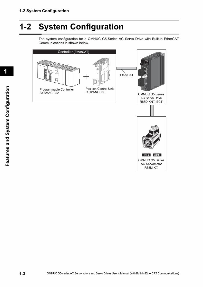
1-2 System ConfigurationThe system configuration for a OMNUC G5-Series AC Servo Drive with Built-in EtherCATCommunications is shown below.
INCNC ABSBS
EtherCAT
Controller (EtherCAT(EtherCAT)
OMNUC G5 SeriesAC Servo DriveR88D-KN@-ECT
OMNUC G5 SeriesAC Servomotor
R88M-K@
Programmable ControllerSYSMAC CJ2
Position Control UnitCJ1W-NC@8@
1-3 OMNUC G5-series AC Servomotors and Servo Drives User’s Manual (with Built-in EtherCAT Communications)
1-3 Names and Functions
1
Features and System C
onfiguration
1-3 Names and FunctionsThis section describes the names and functions of Servo Drive parts.
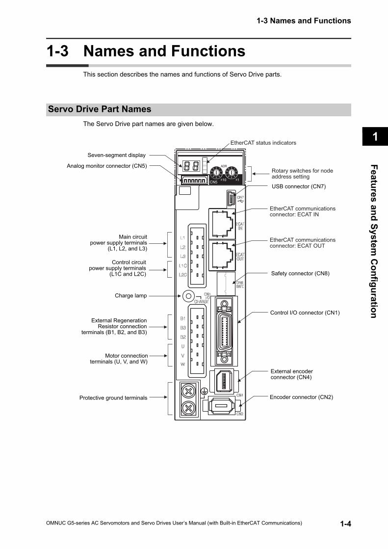
Servo Drive Part NamesThe Servo Drive part names are given below.
USB connector (CN7)
Analog monitor connector (CN5)
Motor connectionterminals (U, V, and W)
Control circuitpower supply terminals
(L1C and L2C)
Main circuitpower supply terminals
(L1, L2, and L3)
External RegenerationResistor connection
terminals (B1, B2, and B3)
Protective ground terminals
Control I/O connector (CN1)
Safety connector (CN8)
External encoderconnector (CN4)
Encoder connector (CN2)
Charge lamp
ADR
Seven-segment display
EtherCAT status indicators
Rotary switches for node address setting
EtherCAT communications connector: ECAT IN
EtherCAT communications connector: ECAT OUT
1-4OMNUC G5-series AC Servomotors and Servo Drives User’s Manual (with Built-in EtherCAT Communications)
1-3 Names and Functions
1
Feat
ures
and
Sys
tem
Con
figur
atio
n
Servo Drive FunctionsThe functions of each part are described below.
DisplayA 2-digit 7-segment display shows the node address, error codes, and other Servo Drivestatus.
Charge LampLights when the main circuit power supply is turned ON.
EtherCAT Status IndicatorsThese indicators show the status of EtherCAT communications.For details, refer to Status Indicators on page 5-2.
Control I/O Connector (CN1)Used for command input signals and I/O signals.
Encoder Connector (CN2)Connector for the encoder installed in the Servomotor.
External Encoder Connector (CN4)Connector for an encoder signal used during fully-closed control.
EtherCAT Communications Connectors (ECAT IN and ECAT OUT)These connectors are for EtherCAT communications.
Analog Monitor Connector (CN5)You can use a special cable to monitor values, such as the motor rotation speed, torquecommand value, etc.
USB Connector (CN7)Communications connector for the computer.
Safety Connector (CN8)Connector for safety devices.If no safety devices are used, keep the factory-set safety bypass connector installed.
1-5 OMNUC G5-series AC Servomotors and Servo Drives User’s Manual (with Built-in EtherCAT Communications)
1-4 System Block Diagram
1
Features and System C
onfiguration
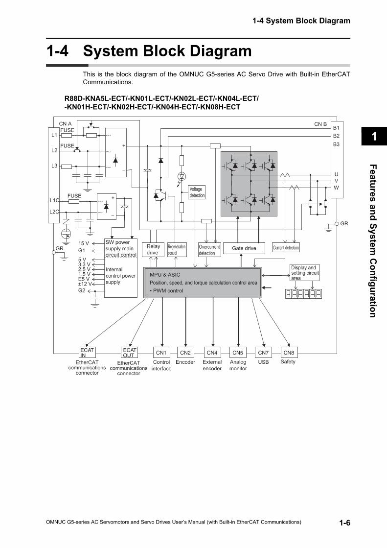
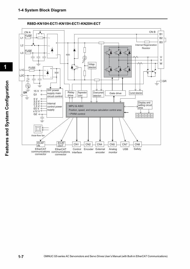
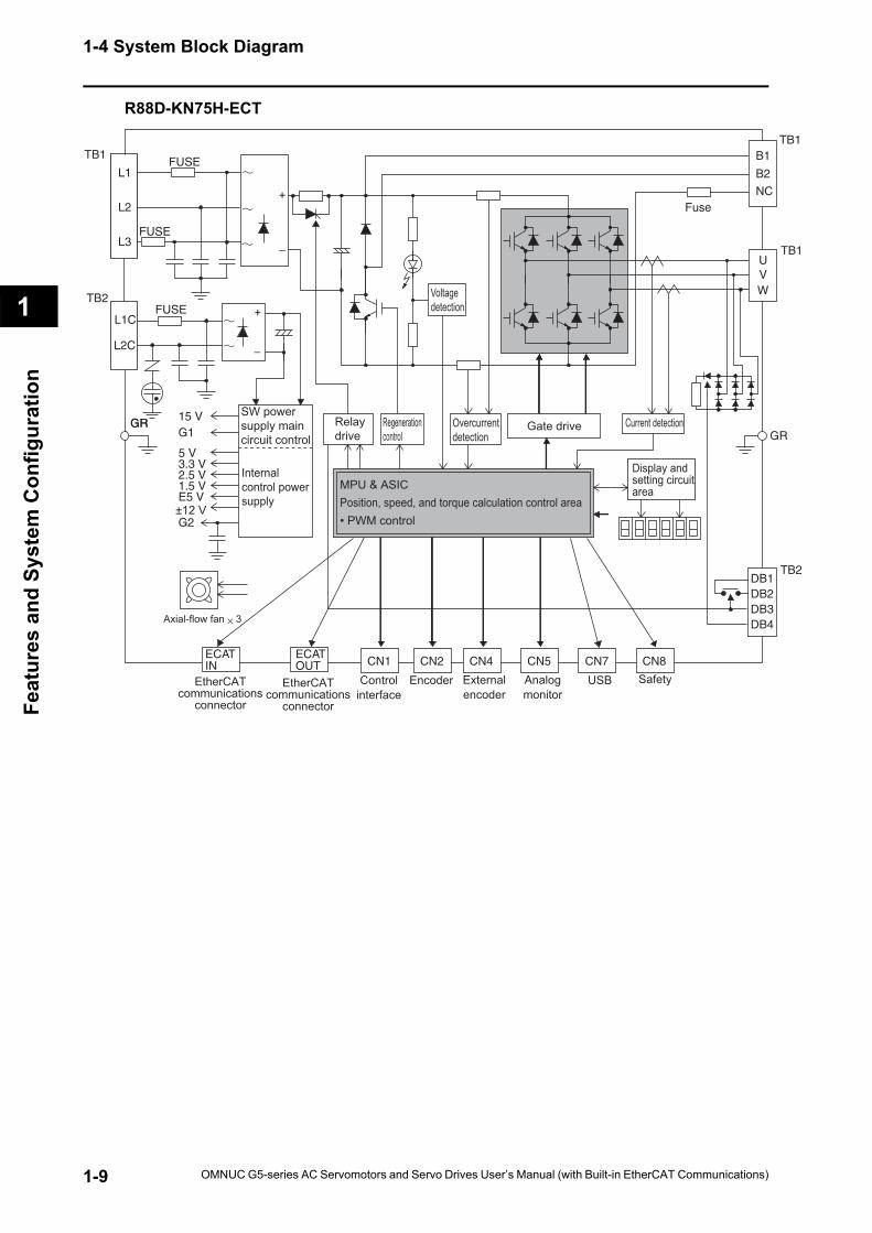
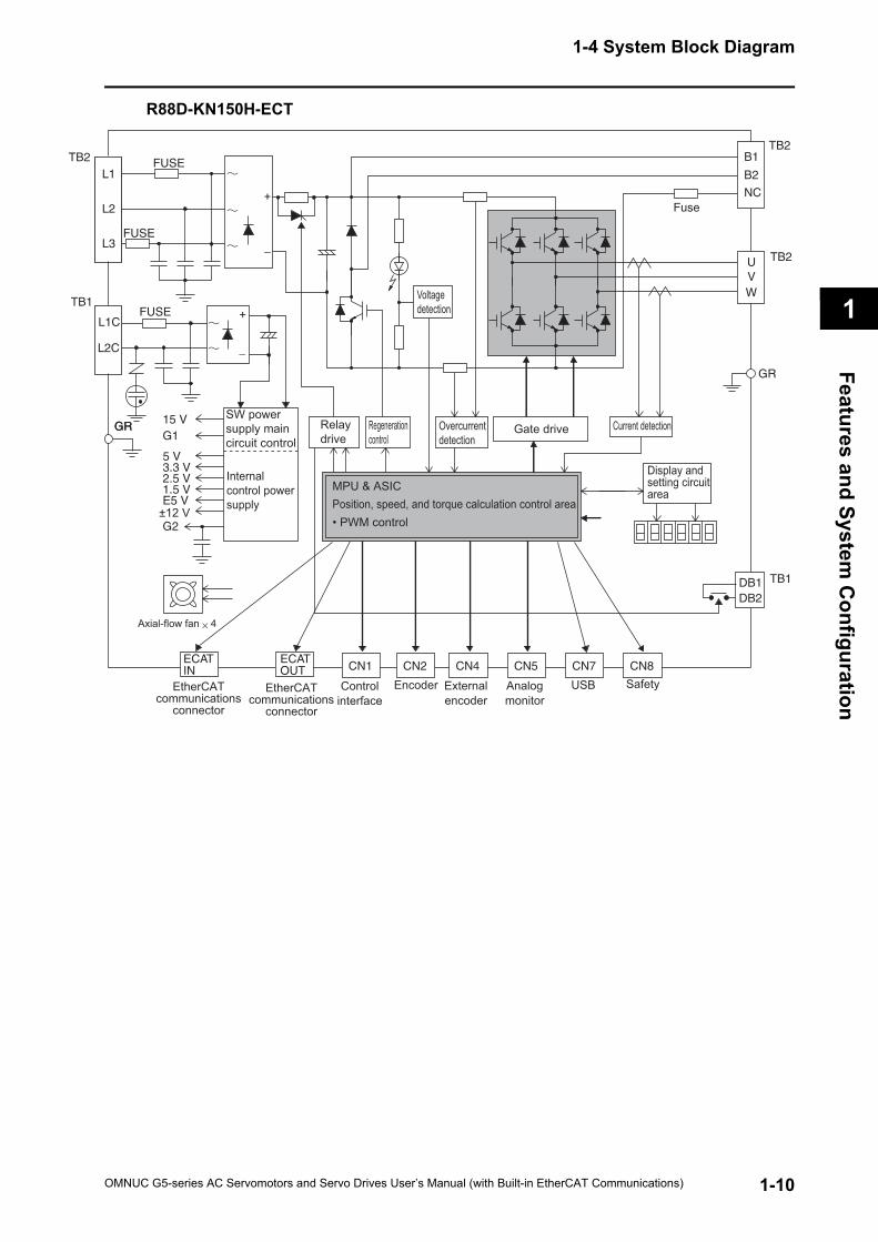
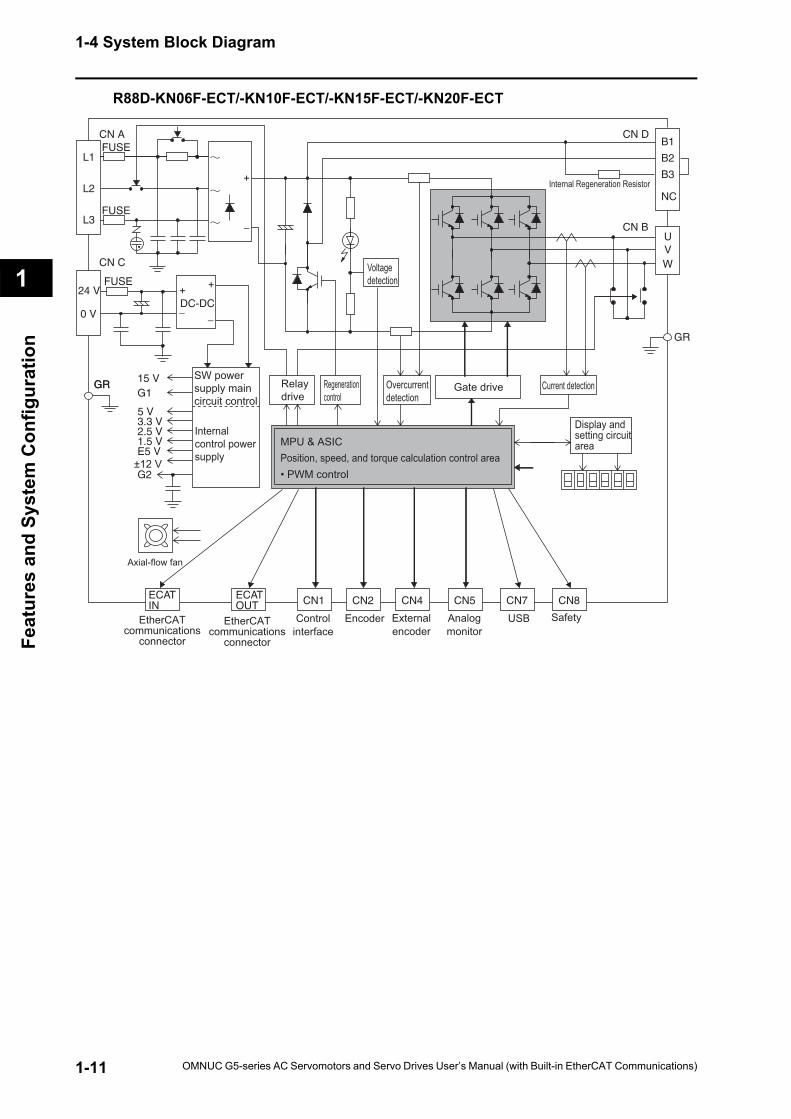
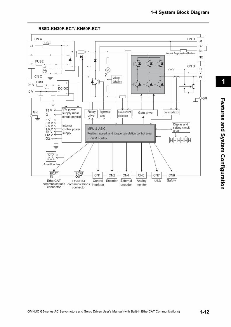
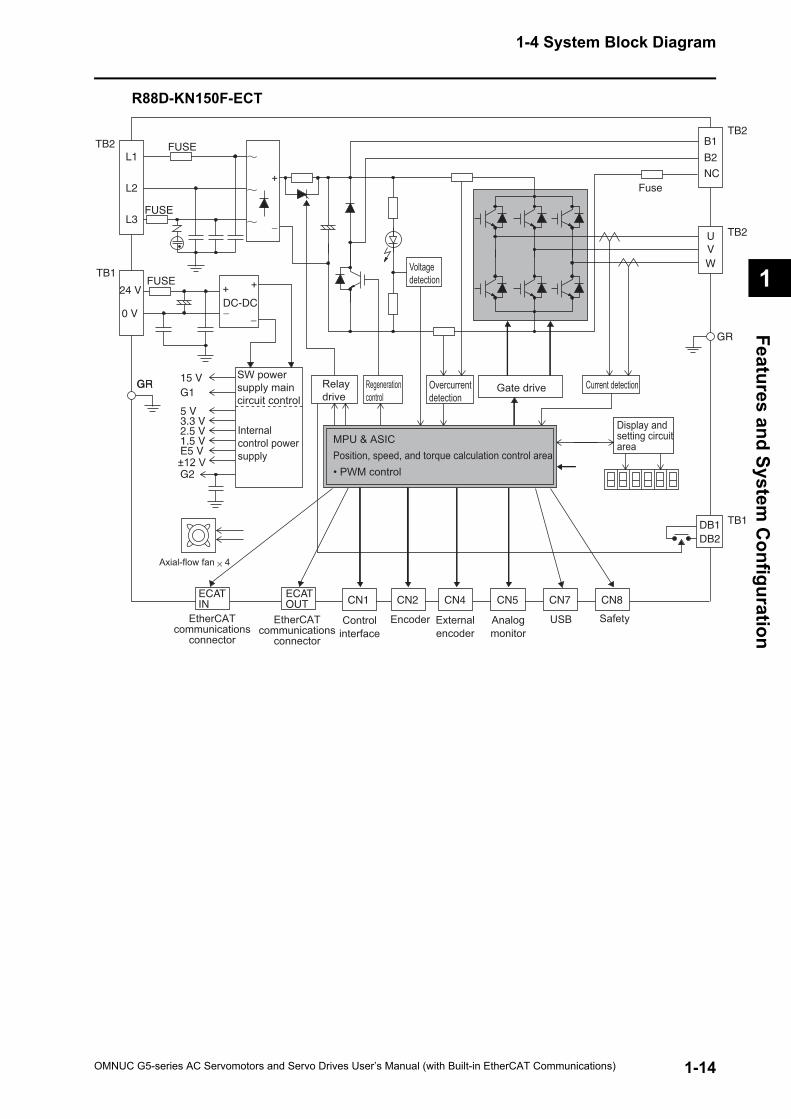
1-4 System Block DiagramThis is the block diagram of the OMNUC G5-series AC Servo Drive with Built-in EtherCATCommunications.
R88D-KNA5L-ECT/-KN01L-ECT/-KN02L-ECT/-KN04L-ECT/-KN01H-ECT/-KN02H-ECT/-KN04H-ECT/-KN08H-ECT
CN2 CN4 CN5 CN7 CN8CN1
Display andsetting circuitarea
Gate driveSW powersupply maincircuit control
Internalcontrol powersupply
GR
L2C
L1C
L3
L2
L1
FUSE
FUSE
FUSE
CN A
+
−
+
−
15 VG1
5 V
2.5 V1.5 V
±12 VE5 V
G2
3.3 V
Overcurrentdetection
Current detection
Voltagedetection
Regenerationcontrol
Relaydrive
GR
Controlinterface
B1B2B3
CN B
UVW
MPU & ASICPosition, speed, and torque calculation control area• PWM control
Encoder Externalencoder
Analogmonitor
USB Safety
ECATIN
ECATOUT
EtherCAT communications
connector
EtherCAT communications
connector
1-6OMNUC G5-series AC Servomotors and Servo Drives User’s Manual (with Built-in EtherCAT Communications)
1-4 System Block Diagram
1
Feat
ures
and
Sys
tem
Con
figur
atio
n
R88D-KN10H-ECT/-KN15H-ECT/-KN20H-ECT
GRGR
L2C
L1C
L3
L2
L1
FUSE
FUSE
FUSE
CN A
15 VG1
5 V
2.5 V1.5 VE5 V
G2
3.3 V
GR
CN2 CN4 CN5 CN7
B1
B2
B3
CN B
UVW
CN8CN1
Display andsetting circuitarea
Gate driveSW powersupply maincircuit control
Internalcontrol powersupply
+
−
+
−
±12 V
Overcurrentdetection
Current detection
Voltagedetection
Regenerationcontrol
Relaydrive
Controlinterface
MPU & ASICPosition, speed, and torque calculation control area• PWM control
Encoder Externalencoder
Analogmonitor
USB Safety
Internal RegenerationResistor
Axial-flow fan
ECATIN
ECATOUT
EtherCAT communications
connector
EtherCAT communications
connector
1-7 OMNUC G5-series AC Servomotors and Servo Drives User’s Manual (with Built-in EtherCAT Communications)

1-4 System Block Diagram
1
Features and System C
onfiguration
R88D-KN30H-ECT/-KN50H-ECT
GRGR
L2C
L1C
L3
L2
L1
FUSE
FUSE
FUSE
CN A
15 VG1
5 V
2.5 V1.5 VE5 V
G2
3.3 V
GR
CN2 CN4 CN5 CN7
B1
B2
B3
NC
CN C
CN BUVW
CN8CN1
Display andsetting circuitarea
Gate driveSW powersupply maincircuit control
Internalcontrol powersupply
+
−
+
−
±12 V
Overcurrentdetection
Current detection
Voltagedetection
Regenerationcontrol
Relaydrive
Controlinterface
MPU & ASICPosition, speed, and torque calculation control area• PWM control
Encoder Externalencoder
Analogmonitor
USB Safety
Internal Regeneration Resistor
Axial-flow fan
ECATIN
ECATOUT
EtherCAT communications
connector
EtherCAT communications
connector
1-8OMNUC G5-series AC Servomotors and Servo Drives User’s Manual (with Built-in EtherCAT Communications)
1-4 System Block Diagram
1
Feat
ures
and
Sys
tem
Con
figur
atio
n
B1
B1
B2
R88D-KN75H-ECT
GRGR
L2C
L1C
L3
L2
L1
FUSE
FUSE
FUSE
15 VG1
5 V
2.5 V1.5 VE5 V
G2
3.3 V
GR
CN2 CN4 CN5 CN7
B1
B2
NC
UVW
CN8CN1
DB1DB2DB3DB4
Display andsetting circuitarea
Gate driveSW powersupply maincircuit control
Internalcontrol powersupply
+
−
+
−
±12 V
Overcurrentdetection
Current detection
Voltagedetection
Regenerationcontrol
Relaydrive
Controlinterface
MPU & ASICPosition, speed, and torque calculation control area• PWM control
Encoder Externalencoder
Analogmonitor
USB Safety
Axial-flow fan × 3
Fuse
ECATIN
ECATOUT
EtherCAT communications
connector
EtherCAT communications
connector
T
T
T
TB1
TB2
1-9 OMNUC G5-series AC Servomotors and Servo Drives User’s Manual (with Built-in EtherCAT Communications)
1-4 System Block Diagram
1
Features and System C
onfiguration
TB2
TB1
R88D-KN150H-ECT
GRGR
L2C
L1C
L3
L2
L1
FUSE
FUSE
FUSE
15 VG1
5 V
2.5 V1.5 VE5 V
G2
3.3 V
GR
CN2 CN4 CN5 CN7
B1
B2
NC
UVW
CN8CN1
DB1DB2
Display andsetting circuitarea
Gate driveSW powersupply maincircuit control
Internalcontrol powersupply
+
−
+
−
±12 V
Overcurrentdetection
Current detection
Voltagedetection
Regenerationcontrol
Relaydrive
Controlinterface
MPU & ASICPosition, speed, and torque calculation control area• PWM control
Encoder Externalencoder
Analogmonitor
USB Safety
Axial-flow fan × 4
Fuse
ECATIN
ECATOUT
EtherCAT communications
connector
EtherCAT communications
connector
TB2
TB2
TB1
1-10OMNUC G5-series AC Servomotors and Servo Drives User’s Manual (with Built-in EtherCAT Communications)
1-4 System Block Diagram
1
Feat
ures
and
Sys
tem
Con
figur
atio
n
R88D-KN06F-ECT/-KN10F-ECT/-KN15F-ECT/-KN20F-ECT
GRGR
0 V
24 V
L3
L2
L1
FUSE
FUSE
FUSE
CN A
CN C
15 VG1
5 V
2.5 V1.5 VE5 V
G2
3.3 V
GR
CN2 CN4 CN5 CN7
B1
B2
B3
NC
CN D
CN BUVW
CN8CN1
DC-DC
Display andsetting circuitarea
Gate driveSW powersupply maincircuit control
Internalcontrol powersupply
+
−
+
−
±12 V
Overcurrentdetection
Current detection
Voltagedetection
Regenerationcontrol
Relaydrive
Controlinterface
MPU & ASICPosition, speed, and torque calculation control area• PWM control
Encoder Externalencoder
Analogmonitor
USB Safety
Internal Regeneration Resistor
Axial-flow fan
+
−
ECATIN
ECATOUT
EtherCAT communications
connector
EtherCAT communications
connector
1-11 OMNUC G5-series AC Servomotors and Servo Drives User’s Manual (with Built-in EtherCAT Communications)
1-4 System Block Diagram
1
Features and System C
onfiguration
R88D-KN30F-ECT/-KN50F-ECT
GRGR
0 V
24 V
L3
L2
L1
FUSE
FUSE
FUSE
CN A
CN C
15 VG1
5 V
2.5 V1.5 VE5 V
G2
3.3 V
GR
CN2 CN4 CN5 CN7
B1
B2
B3
NC
CN D
CN BUVW
CN8CN1
DC-DC
Display andsetting circuitarea
Gate driveSW powersupply maincircuit control
Internalcontrol powersupply
+
−
+
−
±12 V
Overcurrentdetection
Current detection
Voltagedetection
Regenerationcontrol
Relaydrive
Controlinterface
MPU & ASICPosition, speed, and torque calculation control area• PWM control
Encoder Externalencoder
Analogmonitor
USB Safety
Internal Regeneration Resistor
Axial-flow fan
+
−
ECATIN
ECATOUT
EtherCAT communications
connector
EtherCAT communications
connector
1-12OMNUC G5-series AC Servomotors and Servo Drives User’s Manual (with Built-in EtherCAT Communications)

1-4 System Block Diagram
1
Feat
ures
and
Sys
tem
Con
figur
atio
n
B1
B1
B2
R88D-KN75F-ECT
GR
0 V
24 V
L3
L2
L1
FUSE
FUSE
FUSE
15 VG1
5 V
2.5 V1.5 VE5 V
G2
3.3 V
GR
CN2 CN4 CN5 CN7
B1
B2
NC
UVW
CN8CN1
DB1DB2DB3DB4
DC-DC
Display andsetting circuitarea
Gate driveSW powersupply maincircuit control
Internalcontrol powersupply
+
−
+
−
±12 V
Overcurrentdetection
Current detection
Voltagedetection
Regenerationcontrol
Relaydrive
Controlinterface
MPU & ASICPosition, speed, and torque calculation control area• PWM control
Encoder Externalencoder
Analogmonitor
USB Safety
Axial-flow fan × 3
−
+
Fuse
ECATIN
ECATOUT
EtherCAT communications
connector
EtherCAT communications
connector
T
T
T
TB1
TB2
1-13 OMNUC G5-series AC Servomotors and Servo Drives User’s Manual (with Built-in EtherCAT Communications)
1-4 System Block Diagram
1
Features and System C
onfiguration
TB2
TB2
TB1
R88D-KN150F-ECT
GRGR
0 V
24 V
L3
L2
L1
FUSE
FUSE
FUSE
15 VG1
5 V
2.5 V1.5 VE5 V
G2
3.3 V
GR
CN4 CN5 CN7
B1
B2
NC
UVW
CN8
DC-DC
CN2CN1
DB1DB2
Display andsetting circuitarea
Gate driveSW powersupply maincircuit control
Internalcontrol powersupply
+
−
+
−
±12 V
Overcurrentdetection
Current detection
Voltagedetection
Regenerationcontrol
Relaydrive
Controlinterface
MPU & ASICPosition, speed, and torque calculation control area• PWM control
Encoder Externalencoder
Analogmonitor
USB Safety
Axial-flow fan × 4
+
−
Fuse
ECATIN
ECATOUT
EtherCAT communications
connector
EtherCAT communications
connector
TB2
TB1
1-14OMNUC G5-series AC Servomotors and Servo Drives User’s Manual (with Built-in EtherCAT Communications)
1-5 Applicable Standards
1
Feat
ures
and
Sys
tem
Con
figur
atio
n
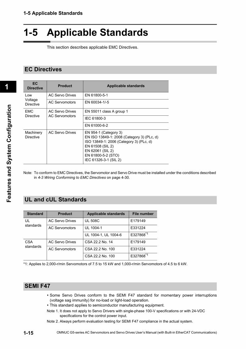
1-5 Applicable StandardsThis section describes applicable EMC Directives.
EC Directives
Note: To conform to EMC Directives, the Servomotor and Servo Drive must be installed under the conditions described in 4-3 Wiring Conforming to EMC Directives on page 4-30.
UL and cUL Standards
*1: Applies to 2,000-r/min Servomotors of 7.5 to 15 kW and 1,000-r/min Servomotors of 4.5 to 6 kW.
SEMI F47Some Servo Drives conform to the SEMI F47 standard for momentary power interruptions(voltage sag immunity) for no-load or light-load operation.This standard applies to semiconductor manufacturing equipment.
Note 1. It does not apply to Servo Drivers with single-phase 100-V specifications or with 24-VDC specifications for the control power input.
Note 2. Always perform evaluation testing for SEMI F47 compliance in the actual system.
EC Directive Product Applicable standards
Low Voltage Directive
AC Servo Drives EN 61800-5-1
AC Servomotors EN 60034-1/-5
EMC Directive
AC Servo DrivesAC Servomotors
EN 55011 class A group 1
IEC 61800-3
EN 61000-6-2
Machinery Directive
AC Servo Drives EN 954-1 (Category 3)EN ISO 13849-1: 2008 (Category 3) (PLc, d)ISO 13849-1: 2006 (Category 3) (PLc, d)EN 61508 (SIL 2)EN 62061 (SIL 2)EN 61800-5-2 (STO)IEC 61326-3-1 (SIL 2)
Standard Product Applicable standards File number
UL standards
AC Servo Drives UL 508C E179149
AC Servomotors UL 1004-1 E331224
UL 1004-1, UL 1004-6 E327868*1
CSA standards
AC Servo Drives CSA 22.2 No. 14 E179149
AC Servomotors CSA 22.2 No. 100 E331224
CSA 22.2 No. 100 E327868*1
1-15 OMNUC G5-series AC Servomotors and Servo Drives User’s Manual (with Built-in EtherCAT Communications)
2
Models and External DimensionsThis chapter explains the models of Servo Drive, Servomotor, and peripheraldevices, and provides the external dimensions and mounting dimensions.
2-1 Servo System Configuration .......................................2-12-2 How to Read Model Numbers ......................................2-32-3 Model Tables .................................................................2-52-4 External and Mounting Dimensions..........................2-232-5 EMC Filter Dimensions...............................................2-67
OMNUC G5-series AC Servomotors and Servo Drives User’s Manual (with Built-in EtherCAT Communications)
2-1 Servo System Configuration
2
Mod
els
and
Exte
rnal
Dim
ensi
ons
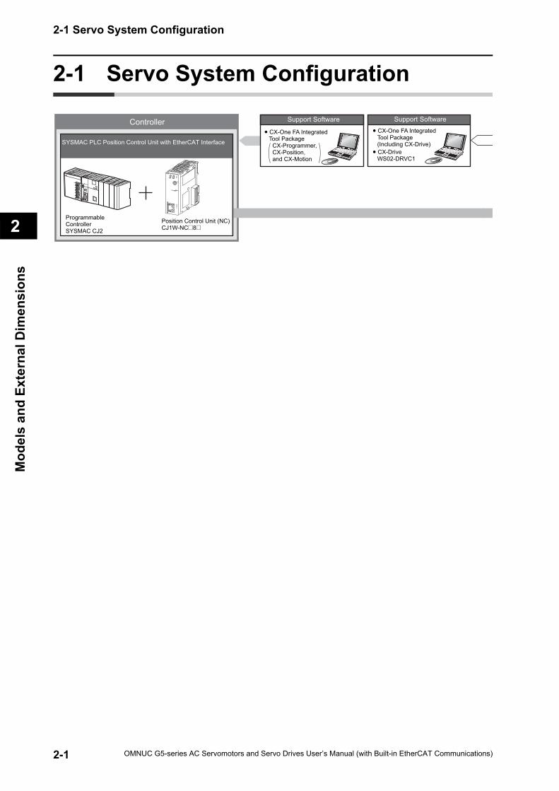
2-1 Servo System Configuration
SYSMAC PLC Position Control Unit with EtherCAT Interface
CX-One FA IntegratedTool Package
CX-Programmer, CX-Position, and CX-Motion
Support Software CX-One FA Integrated
Tool Package (Including CX-Drive)
CX-DriveWS02-DRVC1
Support SoftwareController
Programmable ControllerSYSMAC CJ2
Position Control Unit (NC)CJ1W-NC@8@
2-1 OMNUC G5-series AC Servomotors and Servo Drives User’s Manual (with Built-in EtherCAT Communications)
2-1 Servo System Configuration
2
Models and External D
imensions
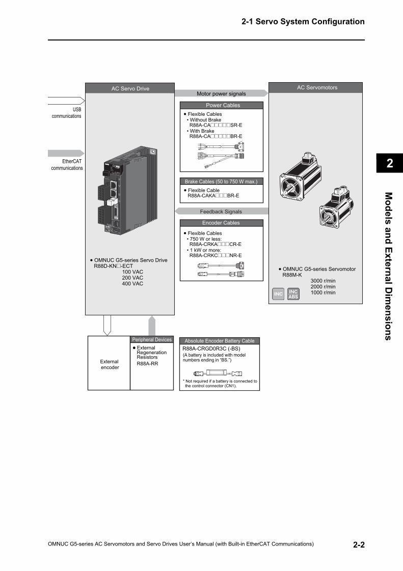
EtherCAT communications
AC Servo Drive
Peripheral Devices External
Regeneration ResistorsR88A-RRExternal
encoder
AC Servomotors
OMNUC G5-series Servo DriveR88D-KN@-ECT
100 VAC 200 VAC 400 VAC
OMNUC G5-series ServomotorR88M-K
3000 r/min 2000 r/min 1000 r/min
Motor power signals
Feedback Signals
Power Cables
• Without BrakeR88A-CA@@@@@SR-E
• With BrakeR88A-CA@@@@@BR-E
Flexible Cables
• 750 W or less:R88A-CRKA@@@CR-E
• 1 kW or more:R88A-CRKC@@@NR-E
Flexible Cables
Encoder Cables
Brake Cables (50 to 750 W max.) Flexible Cable
R88A-CAKA@@@BR-E
USBcommunications
Absolute Encoder Battery Cable
* Not required if a battery is connected to the control connector (CN1).
(A battery is included with model numbers ending in “BS.”)
R88A-CRGD0R3C (-BS)
2-2OMNUC G5-series AC Servomotors and Servo Drives User’s Manual (with Built-in EtherCAT Communications)
2-2 How to Read Model Numbers
2
Mod
els
and
Exte
rnal
Dim
ensi
ons
2-2 How to Read Model NumbersThis section describes how to read and understand the model numbers of Servo Drives andServomotors.
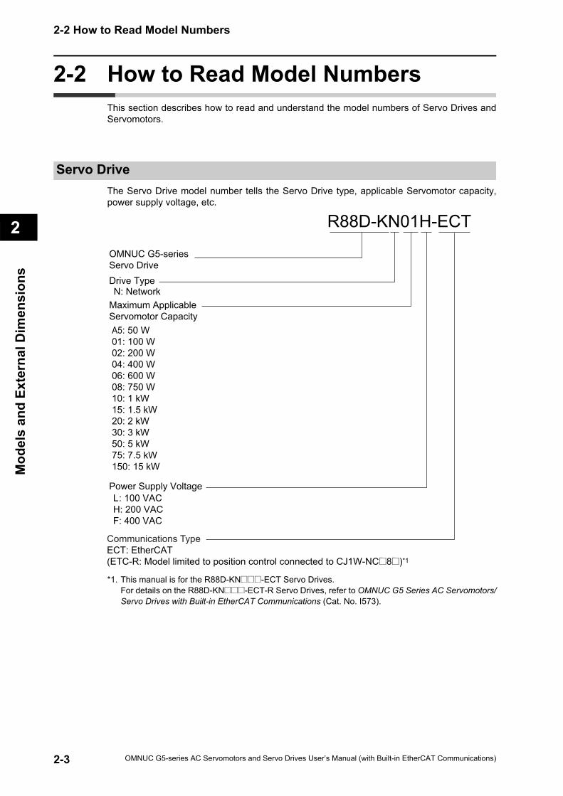
Servo DriveThe Servo Drive model number tells the Servo Drive type, applicable Servomotor capacity,power supply voltage, etc.
*1. This manual is for the R88D-KN@@@-ECT Servo Drives.For details on the R88D-KN@@@-ECT-R Servo Drives, refer to OMNUC G5 Series AC Servomotors/Servo Drives with Built-in EtherCAT Communications (Cat. No. I573).
OMNUC G5-seriesServo DriveDrive Type
Power Supply Voltage
Maximum Applicable Servomotor CapacityA5: 50 W01: 100 W02: 200 W04: 400 W06: 600 W08: 750 W10: 1 kW15: 1.5 kW20: 2 kW30: 3 kW50: 5 kW75: 7.5 kW150: 15 kW
L: 100 VACH: 200 VACF: 400 VAC
N: Network
R88D-KN01H-ECT
Communications TypeECT: EtherCAT(ETC-R: Model limited to position control connected to CJ1W-NC@8@)*1
2-3 OMNUC G5-series AC Servomotors and Servo Drives User’s Manual (with Built-in EtherCAT Communications)
2-2 How to Read Model Numbers
2
Models and External D
imensions
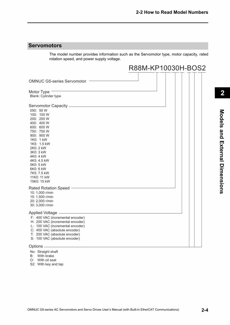
ServomotorsThe model number provides information such as the Servomotor type, motor capacity, ratedrotation speed, and power supply voltage.
R88M-KP10030H-BOS2
OMNUC G5-series Servomotor
Servomotor Capacity
Rated Rotation Speed
Motor TypeBlank: Cylinder type
050: 50 W100: 100 W200: 200 W400: 400 W600: 600 W750: 750 W900: 900 W1K0: 1 kW1K5: 1.5 kW2K0: 2 kW3K0: 3 kW4K0: 4 kW4K5: 4.5 kW5K0: 5 kW6K0: 6 kW7K5: 7.5 kW11K0: 11 kW15K0: 15 kW
10: 1,000 r/min15: 1,500 r/min20: 2,000 r/min30: 3,000 r/min
Applied VoltageF: 400 VAC (incremental encoder)H: 200 VAC (incremental encoder) L: 100 VAC (incremental encoder)C: 400 VAC (absolute encoder)T: 200 VAC (absolute encoder)S: 100 VAC (absolute encoder)
OptionsNo: Straight shaftB: With brakeO: With oil sealS2: With key and tap
2-4OMNUC G5-series AC Servomotors and Servo Drives User’s Manual (with Built-in EtherCAT Communications)
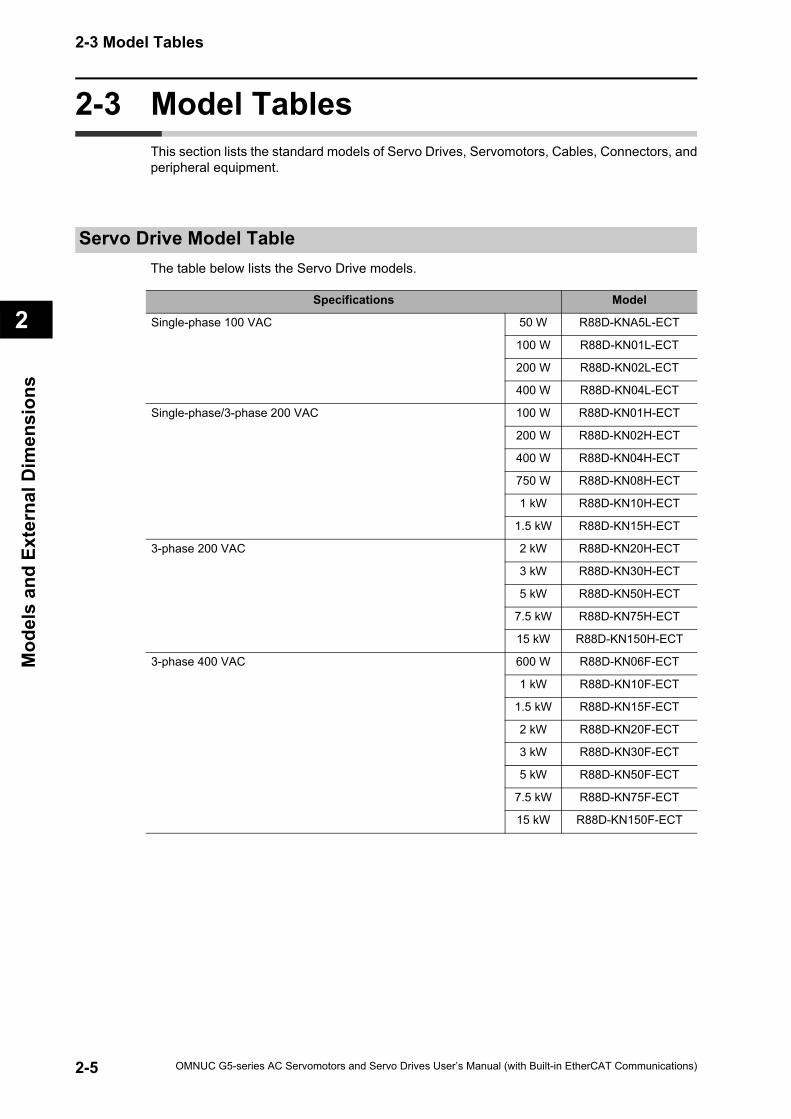
2-3 Model Tables
2
Mod
els
and
Exte
rnal
Dim
ensi
ons
2-3 Model TablesThis section lists the standard models of Servo Drives, Servomotors, Cables, Connectors, andperipheral equipment.
Servo Drive Model TableThe table below lists the Servo Drive models.
Specifications Model
Single-phase 100 VAC 50 W R88D-KNA5L-ECT
100 W R88D-KN01L-ECT
200 W R88D-KN02L-ECT
400 W R88D-KN04L-ECT
Single-phase/3-phase 200 VAC 100 W R88D-KN01H-ECT
200 W R88D-KN02H-ECT
400 W R88D-KN04H-ECT
750 W R88D-KN08H-ECT
1 kW R88D-KN10H-ECT
1.5 kW R88D-KN15H-ECT
3-phase 200 VAC 2 kW R88D-KN20H-ECT
3 kW R88D-KN30H-ECT
5 kW R88D-KN50H-ECT
7.5 kW R88D-KN75H-ECT
15 kW R88D-KN150H-ECT
3-phase 400 VAC 600 W R88D-KN06F-ECT
1 kW R88D-KN10F-ECT
1.5 kW R88D-KN15F-ECT
2 kW R88D-KN20F-ECT
3 kW R88D-KN30F-ECT
5 kW R88D-KN50F-ECT
7.5 kW R88D-KN75F-ECT
15 kW R88D-KN150F-ECT
2-5 OMNUC G5-series AC Servomotors and Servo Drives User’s Manual (with Built-in EtherCAT Communications)
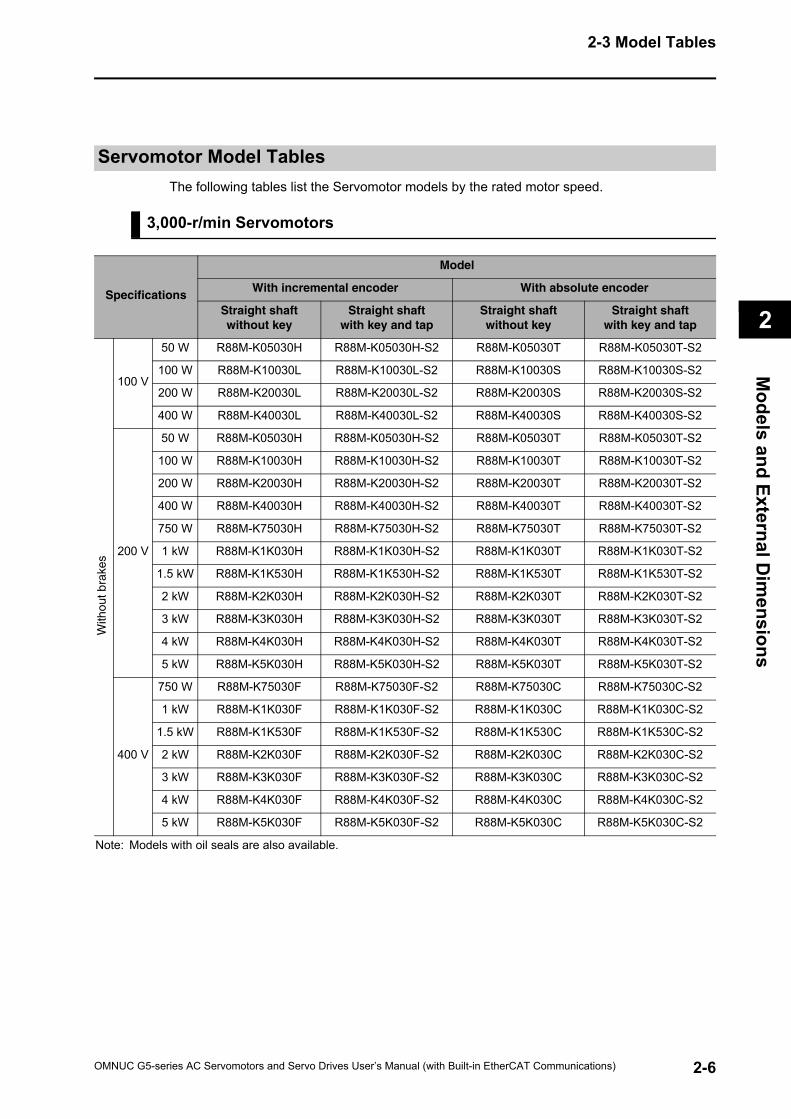
2-3 Model Tables
2
Models and External D
imensions
Servomotor Model TablesThe following tables list the Servomotor models by the rated motor speed.
3,000-r/min Servomotors
Specifications
Model
With incremental encoder With absolute encoder
Straight shaft without key
Straight shaft with key and tap
Straight shaft without key
Straight shaft with key and tap
100 V
50 W R88M-K05030H R88M-K05030H-S2 R88M-K05030T R88M-K05030T-S2
100 W R88M-K10030L R88M-K10030L-S2 R88M-K10030S R88M-K10030S-S2
200 W R88M-K20030L R88M-K20030L-S2 R88M-K20030S R88M-K20030S-S2
400 W R88M-K40030L R88M-K40030L-S2 R88M-K40030S R88M-K40030S-S2
200 V
50 W R88M-K05030H R88M-K05030H-S2 R88M-K05030T R88M-K05030T-S2
100 W R88M-K10030H R88M-K10030H-S2 R88M-K10030T R88M-K10030T-S2
200 W R88M-K20030H R88M-K20030H-S2 R88M-K20030T R88M-K20030T-S2
400 W R88M-K40030H R88M-K40030H-S2 R88M-K40030T R88M-K40030T-S2
750 W R88M-K75030H R88M-K75030H-S2 R88M-K75030T R88M-K75030T-S2
1 kW R88M-K1K030H R88M-K1K030H-S2 R88M-K1K030T R88M-K1K030T-S2
1.5 kW R88M-K1K530H R88M-K1K530H-S2 R88M-K1K530T R88M-K1K530T-S2
2 kW R88M-K2K030H R88M-K2K030H-S2 R88M-K2K030T R88M-K2K030T-S2
3 kW R88M-K3K030H R88M-K3K030H-S2 R88M-K3K030T R88M-K3K030T-S2
4 kW R88M-K4K030H R88M-K4K030H-S2 R88M-K4K030T R88M-K4K030T-S2
5 kW R88M-K5K030H R88M-K5K030H-S2 R88M-K5K030T R88M-K5K030T-S2
400 V
750 W R88M-K75030F R88M-K75030F-S2 R88M-K75030C R88M-K75030C-S2
1 kW R88M-K1K030F R88M-K1K030F-S2 R88M-K1K030C R88M-K1K030C-S2
1.5 kW R88M-K1K530F R88M-K1K530F-S2 R88M-K1K530C R88M-K1K530C-S2
2 kW R88M-K2K030F R88M-K2K030F-S2 R88M-K2K030C R88M-K2K030C-S2
3 kW R88M-K3K030F R88M-K3K030F-S2 R88M-K3K030C R88M-K3K030C-S2
4 kW R88M-K4K030F R88M-K4K030F-S2 R88M-K4K030C R88M-K4K030C-S2
5 kW R88M-K5K030F R88M-K5K030F-S2 R88M-K5K030C R88M-K5K030C-S2
Note: Models with oil seals are also available.
With
out b
rake
s
2-6OMNUC G5-series AC Servomotors and Servo Drives User’s Manual (with Built-in EtherCAT Communications)
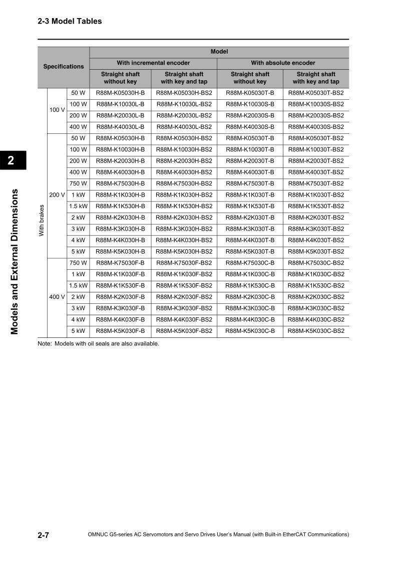
2-3 Model Tables
2
Mod
els
and
Exte
rnal
Dim
ensi
ons
Note: Models with oil seals are also available.
100 V
50 W R88M-K05030H-B R88M-K05030H-BS2 R88M-K05030T-B R88M-K05030T-BS2
100 W R88M-K10030L-B R88M-K10030L-BS2 R88M-K10030S-B R88M-K10030S-BS2
200 W R88M-K20030L-B R88M-K20030L-BS2 R88M-K20030S-B R88M-K20030S-BS2
400 W R88M-K40030L-B R88M-K40030L-BS2 R88M-K40030S-B R88M-K40030S-BS2
200 V
50 W R88M-K05030H-B R88M-K05030H-BS2 R88M-K05030T-B R88M-K05030T-BS2
100 W R88M-K10030H-B R88M-K10030H-BS2 R88M-K10030T-B R88M-K10030T-BS2
200 W R88M-K20030H-B R88M-K20030H-BS2 R88M-K20030T-B R88M-K20030T-BS2
400 W R88M-K40030H-B R88M-K40030H-BS2 R88M-K40030T-B R88M-K40030T-BS2
750 W R88M-K75030H-B R88M-K75030H-BS2 R88M-K75030T-B R88M-K75030T-BS2
1 kW R88M-K1K030H-B R88M-K1K030H-BS2 R88M-K1K030T-B R88M-K1K030T-BS2
1.5 kW R88M-K1K530H-B R88M-K1K530H-BS2 R88M-K1K530T-B R88M-K1K530T-BS2
2 kW R88M-K2K030H-B R88M-K2K030H-BS2 R88M-K2K030T-B R88M-K2K030T-BS2
3 kW R88M-K3K030H-B R88M-K3K030H-BS2 R88M-K3K030T-B R88M-K3K030T-BS2
4 kW R88M-K4K030H-B R88M-K4K030H-BS2 R88M-K4K030T-B R88M-K4K030T-BS2
5 kW R88M-K5K030H-B R88M-K5K030H-BS2 R88M-K5K030T-B R88M-K5K030T-BS2
400 V
750 W R88M-K75030F-B R88M-K75030F-BS2 R88M-K75030C-B R88M-K75030C-BS2
1 kW R88M-K1K030F-B R88M-K1K030F-BS2 R88M-K1K030C-B R88M-K1K030C-BS2
1.5 kW R88M-K1K530F-B R88M-K1K530F-BS2 R88M-K1K530C-B R88M-K1K530C-BS2
2 kW R88M-K2K030F-B R88M-K2K030F-BS2 R88M-K2K030C-B R88M-K2K030C-BS2
3 kW R88M-K3K030F-B R88M-K3K030F-BS2 R88M-K3K030C-B R88M-K3K030C-BS2
4 kW R88M-K4K030F-B R88M-K4K030F-BS2 R88M-K4K030C-B R88M-K4K030C-BS2
5 kW R88M-K5K030F-B R88M-K5K030F-BS2 R88M-K5K030C-B R88M-K5K030C-BS2
Specifications
Model
With incremental encoder With absolute encoder
Straight shaft without key
Straight shaft with key and tap
Straight shaft without key
Straight shaft with key and tap
With
bra
kes
2-7 OMNUC G5-series AC Servomotors and Servo Drives User’s Manual (with Built-in EtherCAT Communications)
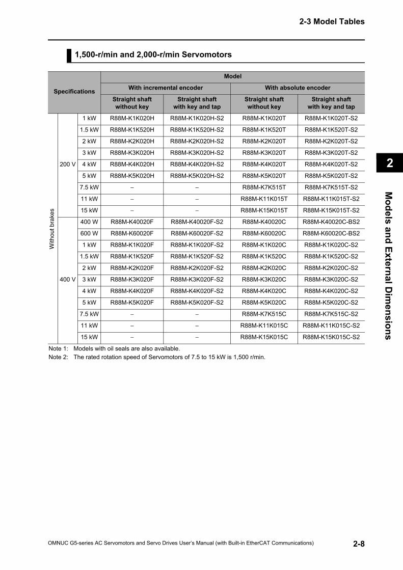
2-3 Model Tables
2
Models and External D
imensions
1,500-r/min and 2,000-r/min Servomotors
Specifications
Model
With incremental encoder With absolute encoder
Straight shaft without key
Straight shaft with key and tap
Straight shaft without key
Straight shaft with key and tap
200 V
1 kW R88M-K1K020H R88M-K1K020H-S2 R88M-K1K020T R88M-K1K020T-S2
1.5 kW R88M-K1K520H R88M-K1K520H-S2 R88M-K1K520T R88M-K1K520T-S2
2 kW R88M-K2K020H R88M-K2K020H-S2 R88M-K2K020T R88M-K2K020T-S2
3 kW R88M-K3K020H R88M-K3K020H-S2 R88M-K3K020T R88M-K3K020T-S2
4 kW R88M-K4K020H R88M-K4K020H-S2 R88M-K4K020T R88M-K4K020T-S2
5 kW R88M-K5K020H R88M-K5K020H-S2 R88M-K5K020T R88M-K5K020T-S2
7.5 kW − − R88M-K7K515T R88M-K7K515T-S2
11 kW − − R88M-K11K015T R88M-K11K015T-S2
15 kW − − R88M-K15K015T R88M-K15K015T-S2
400 V
400 W R88M-K40020F R88M-K40020F-S2 R88M-K40020C R88M-K40020C-BS2
600 W R88M-K60020F R88M-K60020F-S2 R88M-K60020C R88M-K60020C-BS2
1 kW R88M-K1K020F R88M-K1K020F-S2 R88M-K1K020C R88M-K1K020C-S2
1.5 kW R88M-K1K520F R88M-K1K520F-S2 R88M-K1K520C R88M-K1K520C-S2
2 kW R88M-K2K020F R88M-K2K020F-S2 R88M-K2K020C R88M-K2K020C-S2
3 kW R88M-K3K020F R88M-K3K020F-S2 R88M-K3K020C R88M-K3K020C-S2
4 kW R88M-K4K020F R88M-K4K020F-S2 R88M-K4K020C R88M-K4K020C-S2
5 kW R88M-K5K020F R88M-K5K020F-S2 R88M-K5K020C R88M-K5K020C-S2
7.5 kW − − R88M-K7K515C R88M-K7K515C-S2
11 kW − − R88M-K11K015C R88M-K11K015C-S2
15 kW − − R88M-K15K015C R88M-K15K015C-S2
Note 1: Models with oil seals are also available. Note 2: The rated rotation speed of Servomotors of 7.5 to 15 kW is 1,500 r/min.
With
out b
rake
s
2-8OMNUC G5-series AC Servomotors and Servo Drives User’s Manual (with Built-in EtherCAT Communications)
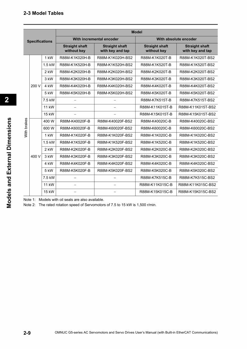
2-3 Model Tables
2
Mod
els
and
Exte
rnal
Dim
ensi
ons
Note 1: Models with oil seals are also available. Note 2: The rated rotation speed of Servomotors of 7.5 to 15 kW is 1,500 r/min.
200 V
1 kW R88M-K1K020H-B R88M-K1K020H-BS2 R88M-K1K020T-B R88M-K1K020T-BS2
1.5 kW R88M-K1K520H-B R88M-K1K520H-BS2 R88M-K1K520T-B R88M-K1K520T-BS2
2 kW R88M-K2K020H-B R88M-K2K020H-BS2 R88M-K2K020T-B R88M-K2K020T-BS2
3 kW R88M-K3K020H-B R88M-K3K020H-BS2 R88M-K3K020T-B R88M-K3K020T-BS2
4 kW R88M-K4K020H-B R88M-K4K020H-BS2 R88M-K4K020T-B R88M-K4K020T-BS2
5 kW R88M-K5K020H-B R88M-K5K020H-BS2 R88M-K5K020T-B R88M-K5K020T-BS2
7.5 kW − − R88M-K7K515T-B R88M-K7K515T-BS2
11 kW − − R88M-K11K015T-B R88M-K11K015T-BS2
15 kW − − R88M-K15K015T-B R88M-K15K015T-BS2
400 V
400 W R88M-K40020F-B R88M-K40020F-BS2 R88M-K40020C-B R88M-K40020C-BS2
600 W R88M-K60020F-B R88M-K60020F-BS2 R88M-K60020C-B R88M-K60020C-BS2
1 kW R88M-K1K020F-B R88M-K1K020F-BS2 R88M-K1K020C-B R88M-K1K020C-BS2
1.5 kW R88M-K1K520F-B R88M-K1K520F-BS2 R88M-K1K520C-B R88M-K1K520C-BS2
2 kW R88M-K2K020F-B R88M-K2K020F-BS2 R88M-K2K020C-B R88M-K2K020C-BS2
3 kW R88M-K3K020F-B R88M-K3K020F-BS2 R88M-K3K020C-B R88M-K3K020C-BS2
4 kW R88M-K4K020F-B R88M-K4K020F-BS2 R88M-K4K020C-B R88M-K4K020C-BS2
5 kW R88M-K5K020F-B R88M-K5K020F-BS2 R88M-K5K020C-B R88M-K5K020C-BS2
7.5 kW − − R88M-K7K515C-B R88M-K7K515C-BS2
11 kW − − R88M-K11K015C-B R88M-K11K015C-BS2
15 kW − − R88M-K15K015C-B R88M-K15K015C-BS2
Specifications
Model
With incremental encoder With absolute encoder
Straight shaft without key
Straight shaft with key and tap
Straight shaft without key
Straight shaft with key and tap
With
bra
kes
2-9 OMNUC G5-series AC Servomotors and Servo Drives User’s Manual (with Built-in EtherCAT Communications)
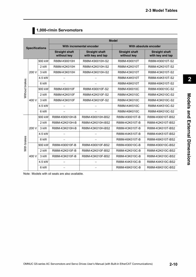
2-3 Model Tables
2
Models and External D
imensions
1,000-r/min Servomotors
Note: Models with oil seals are also available.
Specifications
Model
With incremental encoder With absolute encoder
Straight shaft without key
Straight shaft with key and tap
Straight shaft without key
Straight shaft with key and tap
200 V
900 kW R88M-K90010H R88M-K90010H-S2 R88M-K90010T R88M-K90010T-S2
2 kW R88M-K2K010H R88M-K2K010H-S2 R88M-K2K010T R88M-K2K010T-S2
3 kW R88M-K3K010H R88M-K3K010H-S2 R88M-K3K010T R88M-K3K010T-S2
4.5 kW − − R88M-K4K510T R88M-K4K510T-S2
6 kW − − R88M-K6K010T R88M-K6K010T-S2
400 V
900 kW R88M-K90010F R88M-K90010F-S2 R88M-K90010C R88M-K90010C-S2
2 kW R88M-K2K010F R88M-K2K010F-S2 R88M-K2K010C R88M-K2K010C-S2
3 kW R88M-K3K010F R88M-K3K010F-S2 R88M-K3K010C R88M-K3K010C-S2
4.5 kW − − R88M-K4K510C R88M-K4K510C-S2
6 kW − − R88M-K6K010C R88M-K6K010C-S2
200 V
900 kW R88M-K90010H-B R88M-K90010H-BS2 R88M-K90010T-B R88M-K90010T-BS2
2 kW R88M-K2K010H-B R88M-K2K010H-BS2 R88M-K2K010T-B R88M-K2K010T-BS2
3 kW R88M-K3K010H-B R88M-K3K010H-BS2 R88M-K3K010T-B R88M-K3K010T-BS2
4.5 kW − − R88M-K4K510T-B R88M-K4K510T-BS2
6 kW − − R88M-K6K010T-B R88M-K6K010T-BS2
400 V
900 kW R88M-K90010F-B R88M-K90010F-BS2 R88M-K90010C-B R88M-K90010C-BS2
2 kW R88M-K2K010F-B R88M-K2K010F-BS2 R88M-K2K010C-B R88M-K2K010C-BS2
3 kW R88M-K3K010F-B R88M-K3K010F-BS2 R88M-K3K010C-B R88M-K3K010C-BS2
4.5 kW − − R88M-K4K510C-B R88M-K4K510C-BS2
6 kW − − R88M-K6K010C-B R88M-K6K010C-BS2
With
out b
rake
sW
ith b
rake
s
2-10OMNUC G5-series AC Servomotors and Servo Drives User’s Manual (with Built-in EtherCAT Communications)
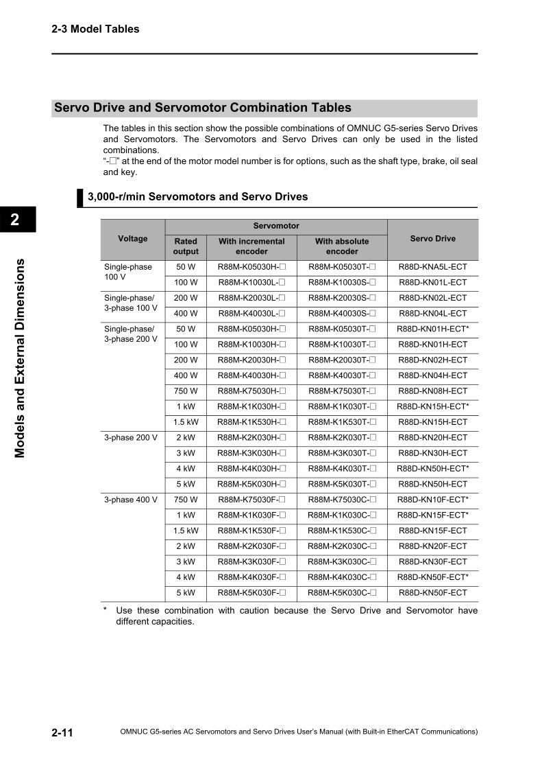
2-3 Model Tables
2
Mod
els
and
Exte
rnal
Dim
ensi
ons
Servo Drive and Servomotor Combination TablesThe tables in this section show the possible combinations of OMNUC G5-series Servo Drivesand Servomotors. The Servomotors and Servo Drives can only be used in the listedcombinations.“-@” at the end of the motor model number is for options, such as the shaft type, brake, oil sealand key.
3,000-r/min Servomotors and Servo Drives
* Use these combination with caution because the Servo Drive and Servomotor havedifferent capacities.
VoltageServomotor
Servo DriveRated output
With incremental encoder
With absolute encoder
Single-phase 100 V
50 W R88M-K05030H-@ R88M-K05030T-@ R88D-KNA5L-ECT
100 W R88M-K10030L-@ R88M-K10030S-@ R88D-KN01L-ECT
Single-phase/3-phase 100 V
200 W R88M-K20030L-@ R88M-K20030S-@ R88D-KN02L-ECT
400 W R88M-K40030L-@ R88M-K40030S-@ R88D-KN04L-ECT
Single-phase/3-phase 200 V
50 W R88M-K05030H-@ R88M-K05030T-@ R88D-KN01H-ECT*
100 W R88M-K10030H-@ R88M-K10030T-@ R88D-KN01H-ECT
200 W R88M-K20030H-@ R88M-K20030T-@ R88D-KN02H-ECT
400 W R88M-K40030H-@ R88M-K40030T-@ R88D-KN04H-ECT
750 W R88M-K75030H-@ R88M-K75030T-@ R88D-KN08H-ECT
1 kW R88M-K1K030H-@ R88M-K1K030T-@ R88D-KN15H-ECT*
1.5 kW R88M-K1K530H-@ R88M-K1K530T-@ R88D-KN15H-ECT
3-phase 200 V 2 kW R88M-K2K030H-@ R88M-K2K030T-@ R88D-KN20H-ECT
3 kW R88M-K3K030H-@ R88M-K3K030T-@ R88D-KN30H-ECT
4 kW R88M-K4K030H-@ R88M-K4K030T-@ R88D-KN50H-ECT*
5 kW R88M-K5K030H-@ R88M-K5K030T-@ R88D-KN50H-ECT
3-phase 400 V 750 W R88M-K75030F-@ R88M-K75030C-@ R88D-KN10F-ECT*
1 kW R88M-K1K030F-@ R88M-K1K030C-@ R88D-KN15F-ECT*
1.5 kW R88M-K1K530F-@ R88M-K1K530C-@ R88D-KN15F-ECT
2 kW R88M-K2K030F-@ R88M-K2K030C-@ R88D-KN20F-ECT
3 kW R88M-K3K030F-@ R88M-K3K030C-@ R88D-KN30F-ECT
4 kW R88M-K4K030F-@ R88M-K4K030C-@ R88D-KN50F-ECT*
5 kW R88M-K5K030F-@ R88M-K5K030C-@ R88D-KN50F-ECT
2-11 OMNUC G5-series AC Servomotors and Servo Drives User’s Manual (with Built-in EtherCAT Communications)
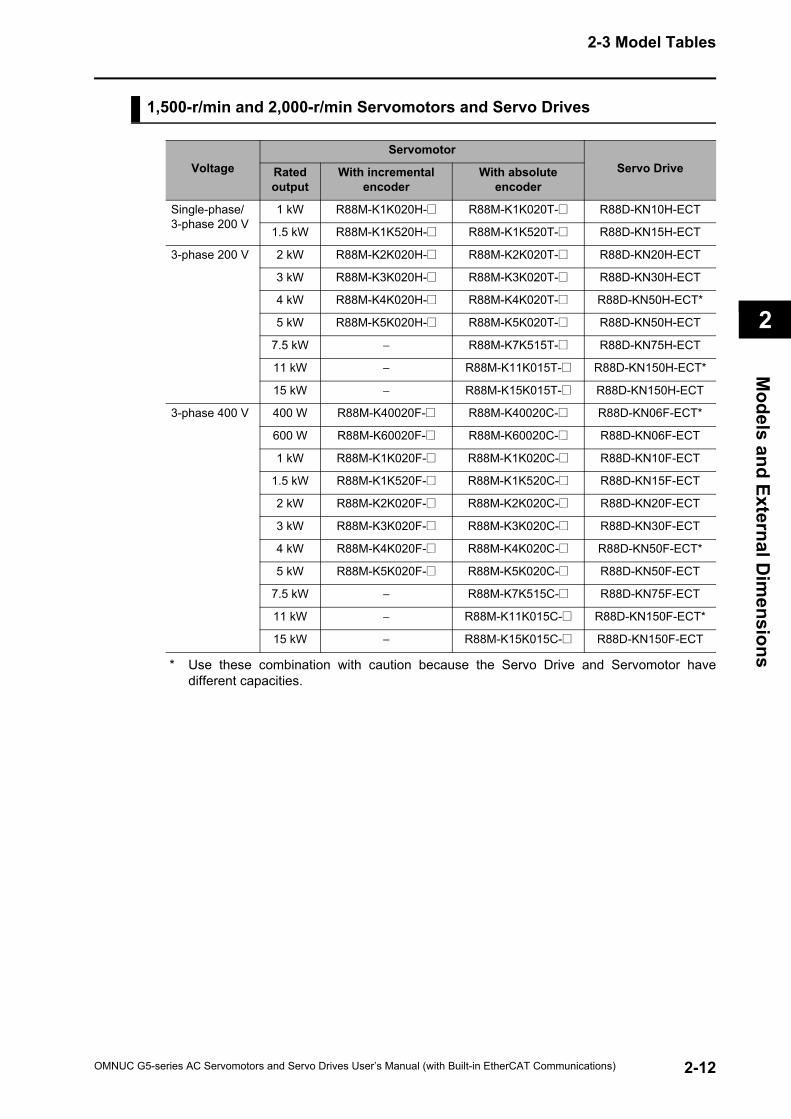
2-3 Model Tables
2
Models and External D
imensions
1,500-r/min and 2,000-r/min Servomotors and Servo Drives
* Use these combination with caution because the Servo Drive and Servomotor havedifferent capacities.
VoltageServomotor
Servo DriveRated output
With incremental encoder
With absolute encoder
Single-phase/3-phase 200 V
1 kW R88M-K1K020H-@ R88M-K1K020T-@ R88D-KN10H-ECT
1.5 kW R88M-K1K520H-@ R88M-K1K520T-@ R88D-KN15H-ECT
3-phase 200 V 2 kW R88M-K2K020H-@ R88M-K2K020T-@ R88D-KN20H-ECT
3 kW R88M-K3K020H-@ R88M-K3K020T-@ R88D-KN30H-ECT
4 kW R88M-K4K020H-@ R88M-K4K020T-@ R88D-KN50H-ECT*
5 kW R88M-K5K020H-@ R88M-K5K020T-@ R88D-KN50H-ECT
7.5 kW − R88M-K7K515T-@ R88D-KN75H-ECT
11 kW − R88M-K11K015T-@ R88D-KN150H-ECT*
15 kW − R88M-K15K015T-@ R88D-KN150H-ECT
3-phase 400 V 400 W R88M-K40020F-@ R88M-K40020C-@ R88D-KN06F-ECT*
600 W R88M-K60020F-@ R88M-K60020C-@ R88D-KN06F-ECT
1 kW R88M-K1K020F-@ R88M-K1K020C-@ R88D-KN10F-ECT
1.5 kW R88M-K1K520F-@ R88M-K1K520C-@ R88D-KN15F-ECT
2 kW R88M-K2K020F-@ R88M-K2K020C-@ R88D-KN20F-ECT
3 kW R88M-K3K020F-@ R88M-K3K020C-@ R88D-KN30F-ECT
4 kW R88M-K4K020F-@ R88M-K4K020C-@ R88D-KN50F-ECT*
5 kW R88M-K5K020F-@ R88M-K5K020C-@ R88D-KN50F-ECT
7.5 kW − R88M-K7K515C-@ R88D-KN75F-ECT
11 kW − R88M-K11K015C-@ R88D-KN150F-ECT*
15 kW − R88M-K15K015C-@ R88D-KN150F-ECT
2-12OMNUC G5-series AC Servomotors and Servo Drives User’s Manual (with Built-in EtherCAT Communications)
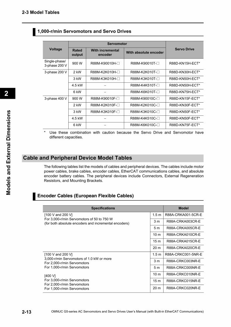
2-3 Model Tables
2
Mod
els
and
Exte
rnal
Dim
ensi
ons
1,000-r/min Servomotors and Servo Drives
* Use these combination with caution because the Servo Drive and Servomotor havedifferent capacities.
Cable and Peripheral Device Model TablesThe following tables list the models of cables and peripheral devices. The cables include motorpower cables, brake cables, encoder cables, EtherCAT communications cables, and absoluteencoder battery cables. The peripheral devices include Connectors, External RegenerationResistors, and Mounting Brackets.
Encoder Cables (European Flexible Cables)
VoltageServomotor
Servo DriveRated output
With incremental encoder With absolute encoder
Single-phase/3-phase 200 V 900 W R88M-K90010H-@ R88M-K90010T-@ R88D-KN15H-ECT*
3-phase 200 V 2 kW R88M-K2K010H-@ R88M-K2K010T-@ R88D-KN30H-ECT*
3 kW R88M-K3K010H-@ R88M-K3K010T-@ R88D-KN50H-ECT*
4.5 kW − R88M-K4K510T-@ R88D-KN50H-ECT*
6 kW − R88M-K6K010T-@ R88D-KN75H-ECT*
3-phase 400 V 900 W R88M-K90010F-@ R88M-K90010C-@ R88D-KN15F-ECT*
2 kW R88M-K2K010F-@ R88M-K2K010C-@ R88D-KN30F-ECT*
3 kW R88M-K3K010F-@ R88M-K3K010C-@ R88D-KN50F-ECT*
4.5 kW − R88M-K4K510C-@ R88D-KN50F-ECT*
6 kW − R88M-K6K010C-@ R88D-KN75F-ECT*
Specifications Model
[100 V and 200 V]For 3,000-r/min Servomotors of 50 to 750 W(for both absolute encoders and incremental encoders)
1.5 m R88A-CRKA001-5CR-E
3 m R88A-CRKA003CR-E
5 m R88A-CRKA005CR-E
10 m R88A-CRKA010CR-E
15 m R88A-CRKA015CR-E
20 m R88A-CRKA020CR-E
[100 V and 200 V]3,000-r/min Servomotors of 1.0 kW or moreFor 2,000-r/min ServomotorsFor 1,000-r/min Servomotors
[400 V]For 3,000-r/min ServomotorsFor 2,000-r/min Servomotors For 1,000-r/min Servomotors
1.5 m R88A-CRKC001-5NR-E
3 m R88A-CRKC003NR-E
5 m R88A-CRKC005NR-E
10 m R88A-CRKC010NR-E
15 m R88A-CRKC015NR-E
20 m R88A-CRKC020NR-E
2-13 OMNUC G5-series AC Servomotors and Servo Drives User’s Manual (with Built-in EtherCAT Communications)
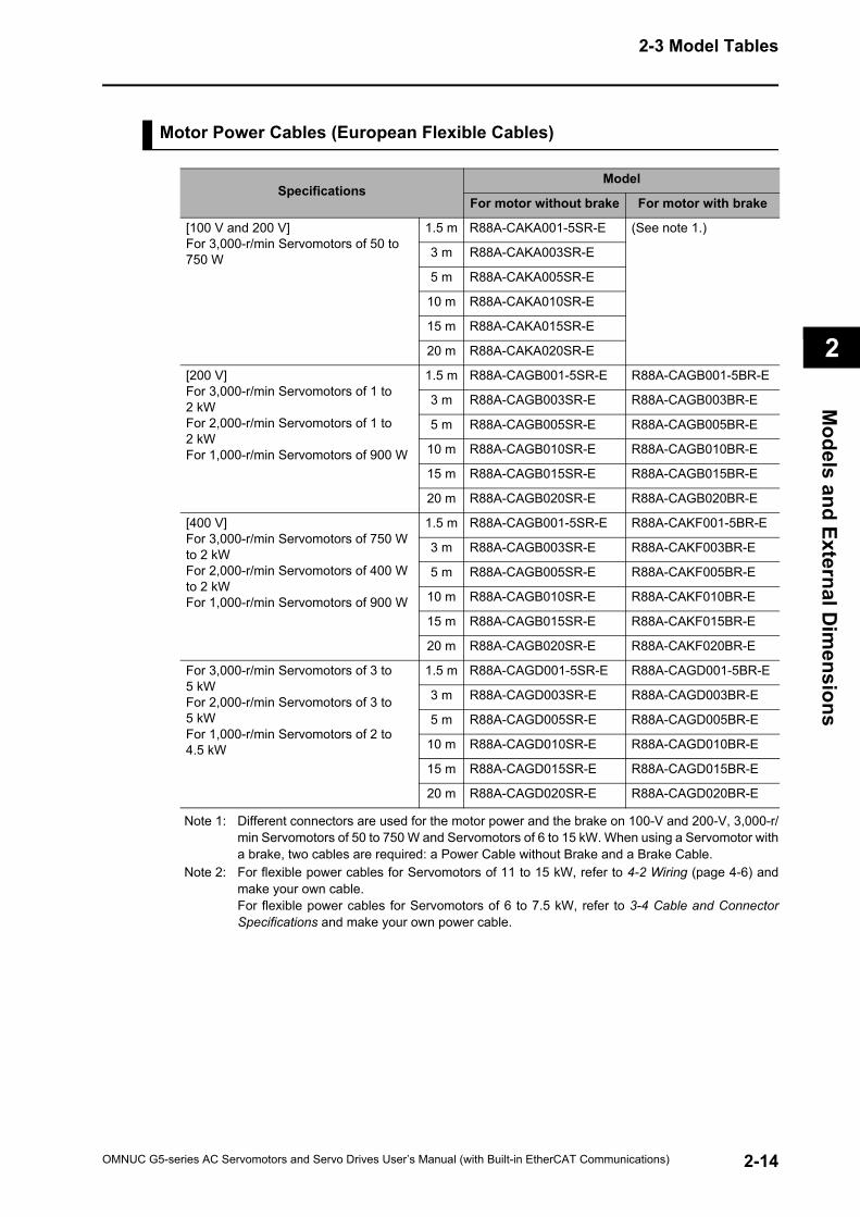
2-3 Model Tables
2
Models and External D
imensions
Motor Power Cables (European Flexible Cables)
Note 1: Different connectors are used for the motor power and the brake on 100-V and 200-V, 3,000-r/min Servomotors of 50 to 750 W and Servomotors of 6 to 15 kW. When using a Servomotor witha brake, two cables are required: a Power Cable without Brake and a Brake Cable.
Note 2: For flexible power cables for Servomotors of 11 to 15 kW, refer to 4-2 Wiring (page 4-6) andmake your own cable.For flexible power cables for Servomotors of 6 to 7.5 kW, refer to 3-4 Cable and ConnectorSpecifications and make your own power cable.
SpecificationsModel
For motor without brake For motor with brake
[100 V and 200 V]For 3,000-r/min Servomotors of 50 to 750 W
1.5 m R88A-CAKA001-5SR-E (See note 1.)
3 m R88A-CAKA003SR-E
5 m R88A-CAKA005SR-E
10 m R88A-CAKA010SR-E
15 m R88A-CAKA015SR-E
20 m R88A-CAKA020SR-E
[200 V]For 3,000-r/min Servomotors of 1 to 2 kWFor 2,000-r/min Servomotors of 1 to 2 kWFor 1,000-r/min Servomotors of 900 W
1.5 m R88A-CAGB001-5SR-E R88A-CAGB001-5BR-E
3 m R88A-CAGB003SR-E R88A-CAGB003BR-E
5 m R88A-CAGB005SR-E R88A-CAGB005BR-E
10 m R88A-CAGB010SR-E R88A-CAGB010BR-E
15 m R88A-CAGB015SR-E R88A-CAGB015BR-E
20 m R88A-CAGB020SR-E R88A-CAGB020BR-E
[400 V]For 3,000-r/min Servomotors of 750 W to 2 kWFor 2,000-r/min Servomotors of 400 W to 2 kWFor 1,000-r/min Servomotors of 900 W
1.5 m R88A-CAGB001-5SR-E R88A-CAKF001-5BR-E
3 m R88A-CAGB003SR-E R88A-CAKF003BR-E
5 m R88A-CAGB005SR-E R88A-CAKF005BR-E
10 m R88A-CAGB010SR-E R88A-CAKF010BR-E
15 m R88A-CAGB015SR-E R88A-CAKF015BR-E
20 m R88A-CAGB020SR-E R88A-CAKF020BR-E
For 3,000-r/min Servomotors of 3 to 5 kWFor 2,000-r/min Servomotors of 3 to 5 kWFor 1,000-r/min Servomotors of 2 to 4.5 kW
1.5 m R88A-CAGD001-5SR-E R88A-CAGD001-5BR-E
3 m R88A-CAGD003SR-E R88A-CAGD003BR-E
5 m R88A-CAGD005SR-E R88A-CAGD005BR-E
10 m R88A-CAGD010SR-E R88A-CAGD010BR-E
15 m R88A-CAGD015SR-E R88A-CAGD015BR-E
20 m R88A-CAGD020SR-E R88A-CAGD020BR-E
2-14OMNUC G5-series AC Servomotors and Servo Drives User’s Manual (with Built-in EtherCAT Communications)
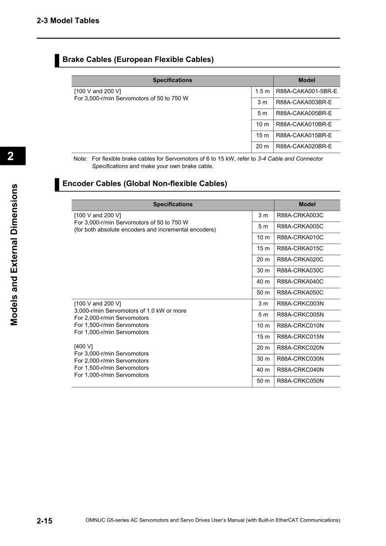
2-3 Model Tables
2
Mod
els
and
Exte
rnal
Dim
ensi
ons
Brake Cables (European Flexible Cables)
Note: For flexible brake cables for Servomotors of 6 to 15 kW, refer to 3-4 Cable and Connector Specifications and make your own brake cable.
Encoder Cables (Global Non-flexible Cables)
Specifications Model
[100 V and 200 V]For 3,000-r/min Servomotors of 50 to 750 W
1.5 m R88A-CAKA001-5BR-E
3 m R88A-CAKA003BR-E
5 m R88A-CAKA005BR-E
10 m R88A-CAKA010BR-E
15 m R88A-CAKA015BR-E
20 m R88A-CAKA020BR-E
Specifications Model
[100 V and 200 V]For 3,000-r/min Servomotors of 50 to 750 W(for both absolute encoders and incremental encoders)
3 m R88A-CRKA003C
5 m R88A-CRKA005C
10 m R88A-CRKA010C
15 m R88A-CRKA015C
20 m R88A-CRKA020C
30 m R88A-CRKA030C
40 m R88A-CRKA040C
50 m R88A-CRKA050C
[100 V and 200 V]3,000-r/min Servomotors of 1.0 kW or moreFor 2,000-r/min ServomotorsFor 1,500-r/min ServomotorsFor 1,000-r/min Servomotors
[400 V]For 3,000-r/min ServomotorsFor 2,000-r/min Servomotors For 1,500-r/min ServomotorsFor 1,000-r/min Servomotors
3 m R88A-CRKC003N
5 m R88A-CRKC005N
10 m R88A-CRKC010N
15 m R88A-CRKC015N
20 m R88A-CRKC020N
30 m R88A-CRKC030N
40 m R88A-CRKC040N
50 m R88A-CRKC050N
2-15 OMNUC G5-series AC Servomotors and Servo Drives User’s Manual (with Built-in EtherCAT Communications)
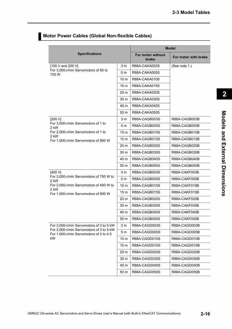
2-3 Model Tables
2
Models and External D
imensions
Motor Power Cables (Global Non-flexible Cables)
SpecificationsModel
For motor without brake For motor with brake
[100 V and 200 V]For 3,000-r/min Servomotors of 50 to 750 W
3 m R88A-CAKA003S (See note 1.)
5 m R88A-CAKA005S
10 m R88A-CAKA010S
15 m R88A-CAKA015S
20 m R88A-CAKA020S
30 m R88A-CAKA030S
40 m R88A-CAKA040S
50 m R88A-CAKA050S
[200 V]For 3,000-r/min Servomotors of 1 to 2 kWFor 2,000-r/min Servomotors of 1 to 2 kWFor 1,000-r/min Servomotors of 900 W
3 m R88A-CAGB003S R88A-CAGB003B
5 m R88A-CAGB005S R88A-CAGB005B
10 m R88A-CAGB010S R88A-CAGB010B
15 m R88A-CAGB015S R88A-CAGB015B
20 m R88A-CAGB020S R88A-CAGB020B
30 m R88A-CAGB030S R88A-CAGB030B
40 m R88A-CAGB040S R88A-CAGB040B
50 m R88A-CAGB050S R88A-CAGB050B
[400 V]For 3,000-r/min Servomotors of 750 W to 2 kWFor 2,000-r/min Servomotors of 400 W to 2 kWFor 1,000-r/min Servomotors of 900 W
3 m R88A-CAGB003S R88A-CAKF003B
5 m R88A-CAGB005S R88A-CAKF005B
10 m R88A-CAGB010S R88A-CAKF010B
15 m R88A-CAGB015S R88A-CAKF015B
20 m R88A-CAGB020S R88A-CAKF020B
30 m R88A-CAGB030S R88A-CAKF030B
40 m R88A-CAGB040S R88A-CAKF040B
50 m R88A-CAGB050S R88A-CAKF050B
For 3,000-r/min Servomotors of 3 to 5 kWFor 2,000-r/min Servomotors of 3 to 5 kWFor 1,000-r/min Servomotors of 2 to 4.5 kW
3 m R88A-CAGD003S R88A-CAGD003B
5 m R88A-CAGD005S R88A-CAGD005B
10 m R88A-CAGD010S R88A-CAGD010B
15 m R88A-CAGD015S R88A-CAGD015B
20 m R88A-CAGD020S R88A-CAGD020B
30 m R88A-CAGD030S R88A-CAGD030B
40 m R88A-CAGD040S R88A-CAGD040B
50 m R88A-CAGD050S R88A-CAGD050B
2-16OMNUC G5-series AC Servomotors and Servo Drives User’s Manual (with Built-in EtherCAT Communications)
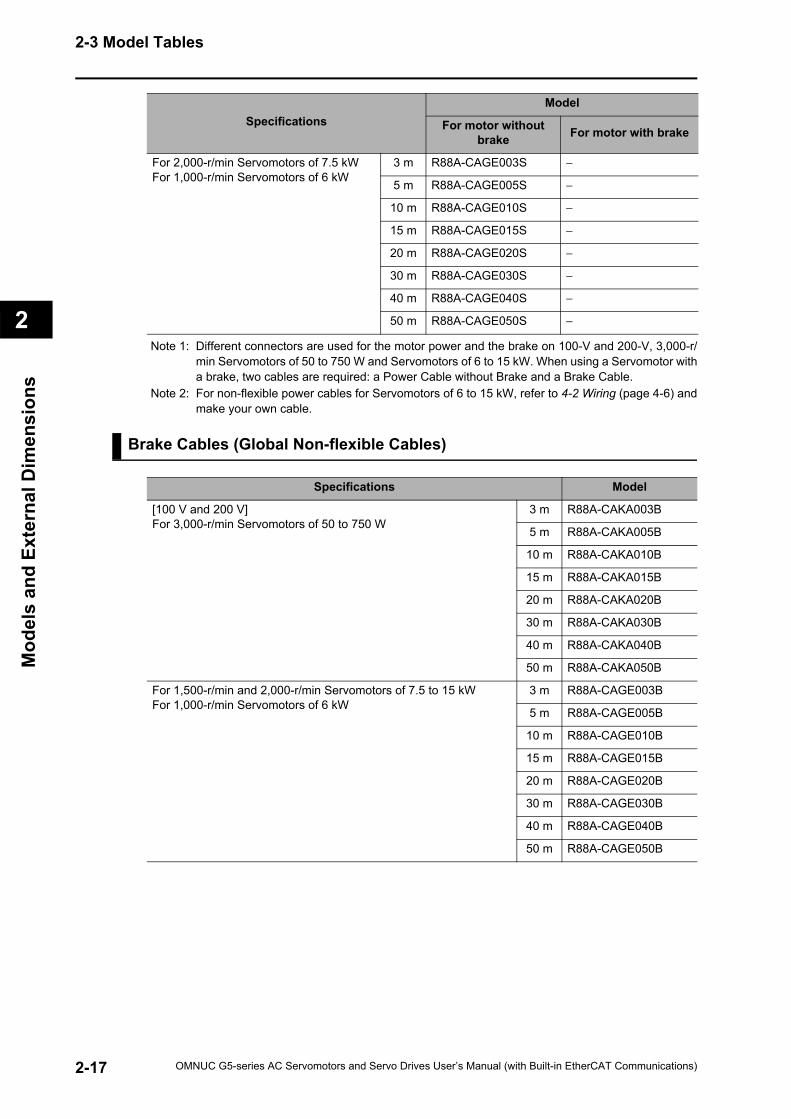
2-3 Model Tables
2
Mod
els
and
Exte
rnal
Dim
ensi
ons
Note 1: Different connectors are used for the motor power and the brake on 100-V and 200-V, 3,000-r/min Servomotors of 50 to 750 W and Servomotors of 6 to 15 kW. When using a Servomotor witha brake, two cables are required: a Power Cable without Brake and a Brake Cable.
Note 2: For non-flexible power cables for Servomotors of 6 to 15 kW, refer to 4-2 Wiring (page 4-6) andmake your own cable.
Brake Cables (Global Non-flexible Cables)
For 2,000-r/min Servomotors of 7.5 kWFor 1,000-r/min Servomotors of 6 kW
3 m R88A-CAGE003S −
5 m R88A-CAGE005S −
10 m R88A-CAGE010S −
15 m R88A-CAGE015S −
20 m R88A-CAGE020S −
30 m R88A-CAGE030S −
40 m R88A-CAGE040S −
50 m R88A-CAGE050S −
SpecificationsModel
For motor without brake For motor with brake
Specifications Model
[100 V and 200 V]For 3,000-r/min Servomotors of 50 to 750 W
3 m R88A-CAKA003B
5 m R88A-CAKA005B
10 m R88A-CAKA010B
15 m R88A-CAKA015B
20 m R88A-CAKA020B
30 m R88A-CAKA030B
40 m R88A-CAKA040B
50 m R88A-CAKA050B
For 1,500-r/min and 2,000-r/min Servomotors of 7.5 to 15 kWFor 1,000-r/min Servomotors of 6 kW
3 m R88A-CAGE003B
5 m R88A-CAGE005B
10 m R88A-CAGE010B
15 m R88A-CAGE015B
20 m R88A-CAGE020B
30 m R88A-CAGE030B
40 m R88A-CAGE040B
50 m R88A-CAGE050B
2-17 OMNUC G5-series AC Servomotors and Servo Drives User’s Manual (with Built-in EtherCAT Communications)
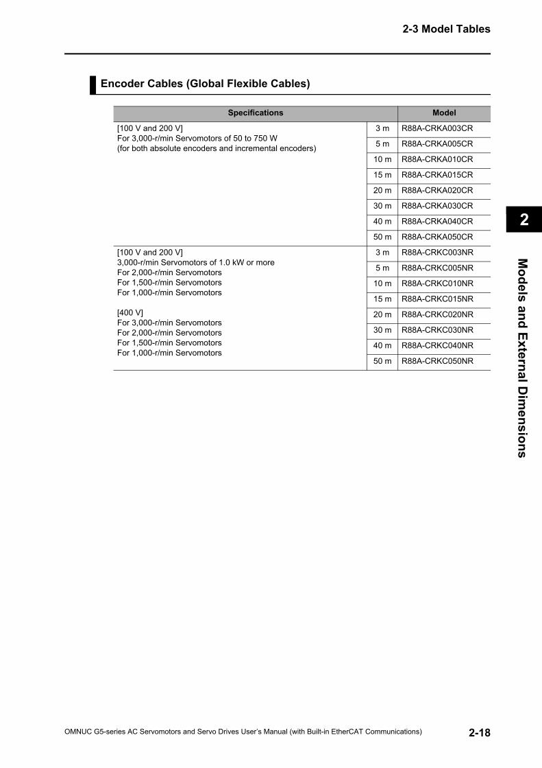
2-3 Model Tables
2
Models and External D
imensions
Encoder Cables (Global Flexible Cables)
Specifications Model
[100 V and 200 V]For 3,000-r/min Servomotors of 50 to 750 W (for both absolute encoders and incremental encoders)
3 m R88A-CRKA003CR
5 m R88A-CRKA005CR
10 m R88A-CRKA010CR
15 m R88A-CRKA015CR
20 m R88A-CRKA020CR
30 m R88A-CRKA030CR
40 m R88A-CRKA040CR
50 m R88A-CRKA050CR
[100 V and 200 V]3,000-r/min Servomotors of 1.0 kW or more For 2,000-r/min Servomotors For 1,500-r/min ServomotorsFor 1,000-r/min Servomotors
[400 V]For 3,000-r/min ServomotorsFor 2,000-r/min ServomotorsFor 1,500-r/min ServomotorsFor 1,000-r/min Servomotors
3 m R88A-CRKC003NR
5 m R88A-CRKC005NR
10 m R88A-CRKC010NR
15 m R88A-CRKC015NR
20 m R88A-CRKC020NR
30 m R88A-CRKC030NR
40 m R88A-CRKC040NR
50 m R88A-CRKC050NR
2-18OMNUC G5-series AC Servomotors and Servo Drives User’s Manual (with Built-in EtherCAT Communications)
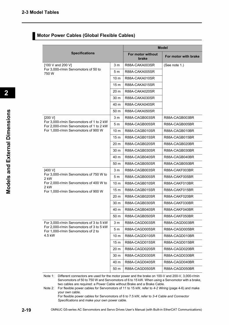
2-3 Model Tables
2
Mod
els
and
Exte
rnal
Dim
ensi
ons
Motor Power Cables (Global Flexible Cables)
Note 1: Different connectors are used for the motor power and the brake on 100-V and 200-V, 3,000-r/min Servomotors of 50 to 750 W and Servomotors of 6 to 15 kW. When using a Servomotor with a brake, two cables are required: a Power Cable without Brake and a Brake Cable.
Note 2: For flexible power cables for Servomotors of 11 to 15 kW, refer to 4-2 Wiring (page 4-6) and make your own cable. For flexible power cables for Servomotors of 6 to 7.5 kW, refer to 3-4 Cable and Connector Specifications and make your own power cable.
SpecificationsModel
For motor without brake For motor with brake
[100 V and 200 V]For 3,000-r/min Servomotors of 50 to 750 W
3 m R88A-CAKA003SR (See note 1.)
5 m R88A-CAKA005SR
10 m R88A-CAKA010SR
15 m R88A-CAKA015SR
20 m R88A-CAKA020SR
30 m R88A-CAKA030SR
40 m R88A-CAKA040SR
50 m R88A-CAKA050SR
[200 V]For 3,000-r/min Servomotors of 1 to 2 kW For 2,000-r/min Servomotors of 1 to 2 kW For 1,000-r/min Servomotors of 900 W
3 m R88A-CAGB003SR R88A-CAGB003BR
5 m R88A-CAGB005SR R88A-CAGB005BR
10 m R88A-CAGB010SR R88A-CAGB010BR
15 m R88A-CAGB015SR R88A-CAGB015BR
20 m R88A-CAGB020SR R88A-CAGB020BR
30 m R88A-CAGB030SR R88A-CAGB030BR
40 m R88A-CAGB040SR R88A-CAGB040BR
50 m R88A-CAGB050SR R88A-CAGB050BR
[400 V]For 3,000-r/min Servomotors of 750 W to 2 kWFor 2,000-r/min Servomotors of 400 W to 2 kWFor 1,000-r/min Servomotors of 900 W
3 m R88A-CAGB003SR R88A-CAKF003BR
5 m R88A-CAGB005SR R88A-CAKF005BR
10 m R88A-CAGB010SR R88A-CAKF010BR
15 m R88A-CAGB015SR R88A-CAKF015BR
20 m R88A-CAGB020SR R88A-CAKF020BR
30 m R88A-CAGB030SR R88A-CAKF030BR
40 m R88A-CAGB040SR R88A-CAKF040BR
50 m R88A-CAGB050SR R88A-CAKF050BR
For 3,000-r/min Servomotors of 3 to 5 kWFor 2,000-r/min Servomotors of 3 to 5 kWFor 1,000-r/min Servomotors of 2 to 4.5 kW
3 m R88A-CAGD003SR R88A-CAGD003BR
5 m R88A-CAGD005SR R88A-CAGD005BR
10 m R88A-CAGD010SR R88A-CAGD010BR
15 m R88A-CAGD015SR R88A-CAGD015BR
20 m R88A-CAGD020SR R88A-CAGD020BR
30 m R88A-CAGD030SR R88A-CAGD030BR
40 m R88A-CAGD040SR R88A-CAGD040BR
50 m R88A-CAGD050SR R88A-CAGD050BR
2-19 OMNUC G5-series AC Servomotors and Servo Drives User’s Manual (with Built-in EtherCAT Communications)
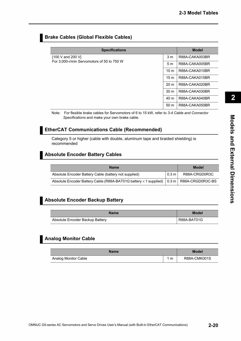
2-3 Model Tables
2
Models and External D
imensions
Brake Cables (Global Flexible Cables)
Note: For flexible brake cables for Servomotors of 6 to 15 kW, refer to 3-4 Cable and Connector Specifications and make your own brake cable.
EtherCAT Communications Cable (Recommended)
Category 5 or higher (cable with double, aluminum tape and braided shielding) is recommended
Absolute Encoder Battery Cables
Absolute Encoder Backup Battery
Analog Monitor Cable
Specifications Model
[100 V and 200 V]For 3,000-r/min Servomotors of 50 to 750 W
3 m R88A-CAKA003BR
5 m R88A-CAKA005BR
10 m R88A-CAKA010BR
15 m R88A-CAKA015BR
20 m R88A-CAKA020BR
30 m R88A-CAKA030BR
40 m R88A-CAKA040BR
50 m R88A-CAKA050BR
Name Model
Absolute Encoder Battery Cable (battery not supplied) 0.3 m R88A-CRGD0R3C
Absolute Encoder Battery Cable (R88A-BAT01G battery × 1 supplied) 0.3 m R88A-CRGD0R3C-BS
Name Model
Absolute Encoder Backup Battery R88A-BAT01G
Name Model
Analog Monitor Cable 1 m R88A-CMK001S
2-20OMNUC G5-series AC Servomotors and Servo Drives User’s Manual (with Built-in EtherCAT Communications)
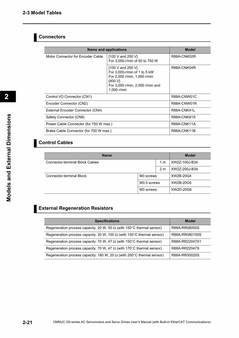
2-3 Model Tables
2
Mod
els
and
Exte
rnal
Dim
ensi
ons
Connectors
Control Cables
External Regeneration Resistors
Name and applications Model
Motor Connector for Encoder Cable [100 V and 200 V]For 3,000-r/min of 50 to 750 W
R88A-CNK02R
[100 V and 200 V]For 3,000-r/min of 1 to 5 kWFor 2,000 r/min, 1,000 r/min[400 V]For 3,000 r/min, 2,000 r/min and 1,000 r/min
R88A-CNK04R
Control I/O Connector (CN1) R88A-CNW01C
Encoder Connector (CN2) R88A-CNW01R
External Encoder Connector (CN4) R88A-CNK41L
Safety Connector (CN8) R88A-CNK81S
Power Cable Connector (for 750 W max.) R88A-CNK11A
Brake Cable Connector (for 750 W max.) R88A-CNK11B
Name Model
Connector-terminal Block Cables 1 m XW2Z-100J-B34
2 m XW2Z-200J-B34
Connector-terminal Block M3 screws XW2B-20G4
M3.5 screws XW2B-20G5
M3 screws XW2D-20G6
Specifications Model
Regeneration process capacity: 20 W, 50 Ω (with 150°C thermal sensor) R88A-RR08050S
Regeneration process capacity: 20 W, 100 Ω (with 150°C thermal sensor) R88A-RR080100S
Regeneration process capacity: 70 W, 47 Ω (with 150°C thermal sensor) R88A-RR22047S1
Regeneration process capacity: 70 W, 47 Ω (with 170°C thermal sensor) R88A-RR22047S
Regeneration process capacity: 180 W, 20 Ω (with 200°C thermal sensor) R88A-RR50020S
2-21 OMNUC G5-series AC Servomotors and Servo Drives User’s Manual (with Built-in EtherCAT Communications)
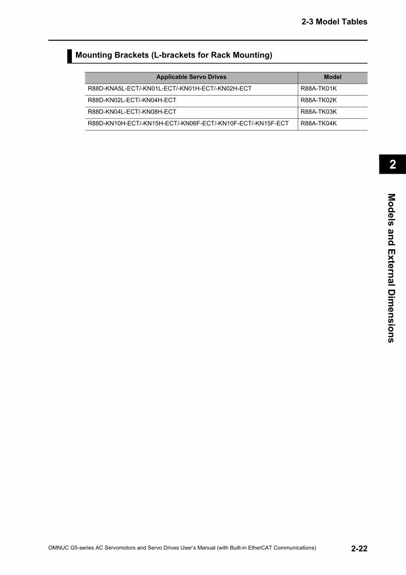
2-3 Model Tables
2
Models and External D
imensions
Mounting Brackets (L-brackets for Rack Mounting)
Applicable Servo Drives Model
R88D-KNA5L-ECT/-KN01L-ECT/-KN01H-ECT/-KN02H-ECT R88A-TK01K
R88D-KN02L-ECT/-KN04H-ECT R88A-TK02K
R88D-KN04L-ECT/-KN08H-ECT R88A-TK03K
R88D-KN10H-ECT/-KN15H-ECT/-KN06F-ECT/-KN10F-ECT/-KN15F-ECT R88A-TK04K
2-22OMNUC G5-series AC Servomotors and Servo Drives User’s Manual (with Built-in EtherCAT Communications)
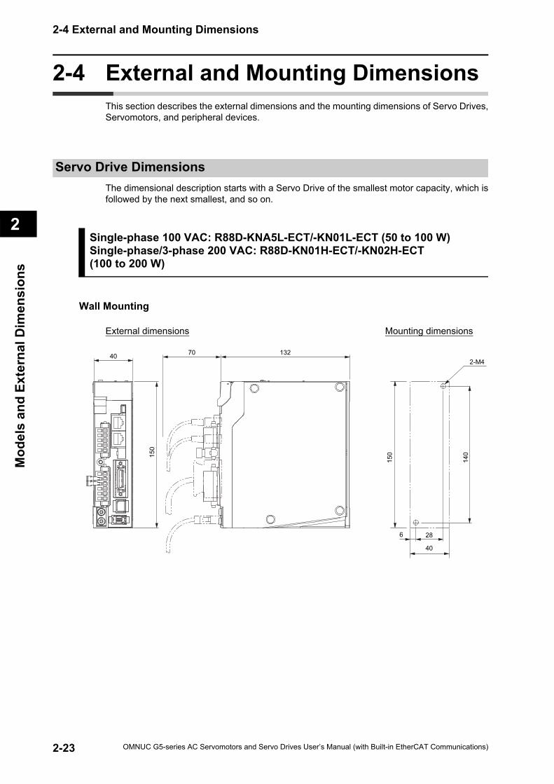
2-4 External and Mounting Dimensions
2
Mod
els
and
Exte
rnal
Dim
ensi
ons
2-4 External and Mounting DimensionsThis section describes the external dimensions and the mounting dimensions of Servo Drives,Servomotors, and peripheral devices.
Servo Drive DimensionsThe dimensional description starts with a Servo Drive of the smallest motor capacity, which isfollowed by the next smallest, and so on.
Single-phase 100 VAC: R88D-KNA5L-ECT/-KN01L-ECT (50 to 100 W) Single-phase/3-phase 200 VAC: R88D-KN01H-ECT/-KN02H-ECT (100 to 200 W)
Wall Mounting
External dimensions Mounting dimensions
1327040
150
40
286
150
140
2-M4
2-23 OMNUC G5-series AC Servomotors and Servo Drives User’s Manual (with Built-in EtherCAT Communications)
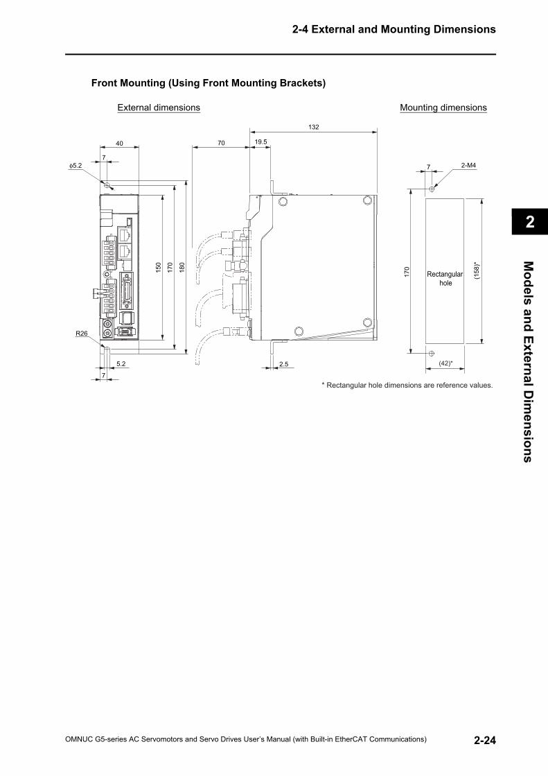
2-4 External and Mounting Dimensions
2
Models and External D
imensions
Front Mounting (Using Front Mounting Brackets)
External dimensions Mounting dimensions
40
7
180
170
150
5.2
R26
7
φ5.2
2.5
132
19.5
7 2-M4
70
170
(42)*
(158
)*
* Rectangular hole dimensions are reference values.
Rectangular hole
2-24OMNUC G5-series AC Servomotors and Servo Drives User’s Manual (with Built-in EtherCAT Communications)
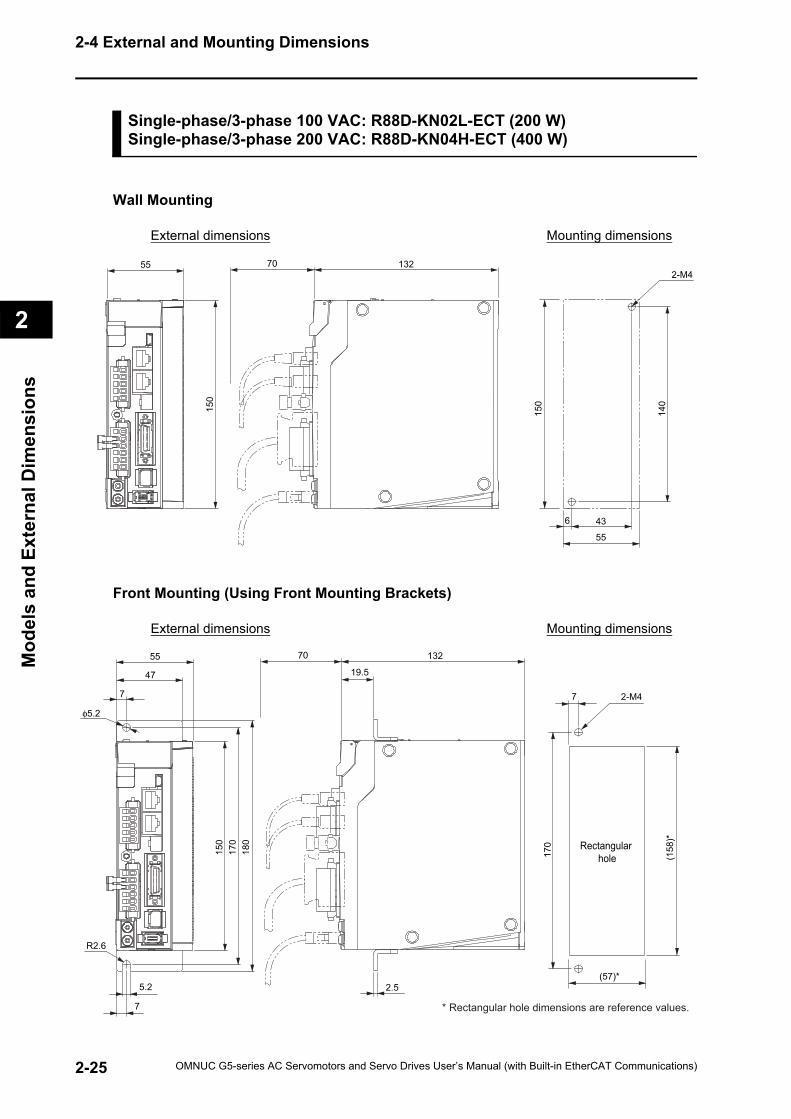
2-4 External and Mounting Dimensions
2
Mod
els
and
Exte
rnal
Dim
ensi
ons
Single-phase/3-phase 100 VAC: R88D-KN02L-ECT (200 W)Single-phase/3-phase 200 VAC: R88D-KN04H-ECT (400 W)
Wall Mounting
External dimensions Mounting dimensions
Front Mounting (Using Front Mounting Brackets)
External dimensions Mounting dimensions
55
150
132
150
436
55
140
702-M4
55
47
7
φ5.2
180
170
150
7
5.2
R2.6
2.5
132
19.5
7
170
70
2-M4
(57)*
(158
)*
* Rectangular hole dimensions are reference values.
Rectangular hole
2-25 OMNUC G5-series AC Servomotors and Servo Drives User’s Manual (with Built-in EtherCAT Communications)
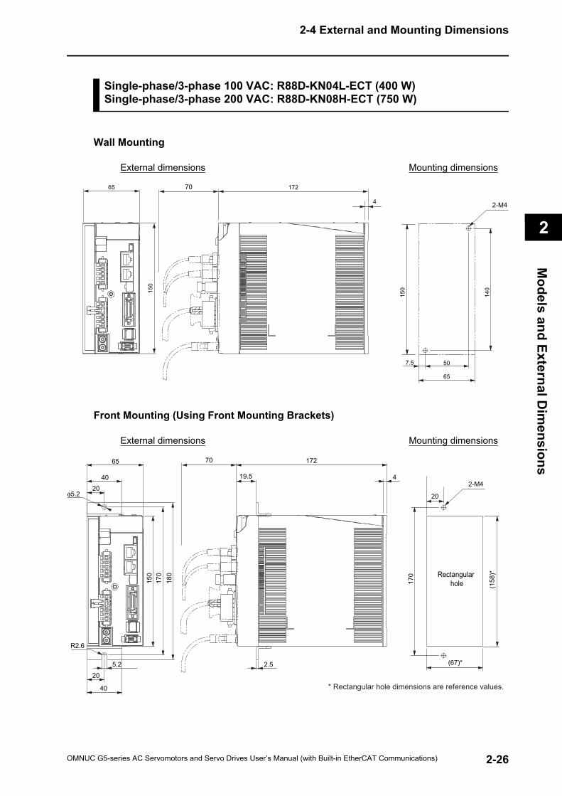
2-4 External and Mounting Dimensions
2
Models and External D
imensions
Single-phase/3-phase 100 VAC: R88D-KN04L-ECT (400 W) Single-phase/3-phase 200 VAC: R88D-KN08H-ECT (750 W)
Wall Mounting
External dimensions Mounting dimensions
Front Mounting (Using Front Mounting Brackets)
External dimensions Mounting dimensions
172
4
65
150
150
140
507.5
65
70
2-M4
65
4020
φ5.2
R2.6
20
40
5.2
180
170
150
172
419.5
2.5
170
20
70
2-M4
(67)*
(158
)*
* Rectangular hole dimensions are reference values.
Rectangular hole
2-26OMNUC G5-series AC Servomotors and Servo Drives User’s Manual (with Built-in EtherCAT Communications)
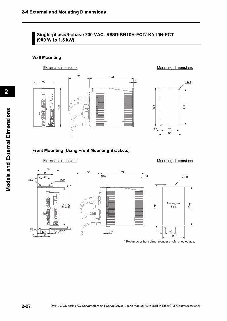
2-4 External and Mounting Dimensions
2
Mod
els
and
Exte
rnal
Dim
ensi
ons
Single-phase/3-phase 200 VAC: R88D-KN10H-ECT/-KN15H-ECT(900 W to 1.5 kW)
Wall Mounting
External dimensions Mounting dimensions
Front Mounting (Using Front Mounting Brackets)
External dimensions Mounting dimensions
86
150
1724 2-M4
140
150
708.586
70
170
4011R2.6
R2.6
φ5.2 φ5.2
170
180
150
86
604010
5.25.24010
19.5172
470
4-M4
2.5(88)*
(158
)*
* Rectangular hole dimensions are reference values.
Rectangular hole
2-27 OMNUC G5-series AC Servomotors and Servo Drives User’s Manual (with Built-in EtherCAT Communications)
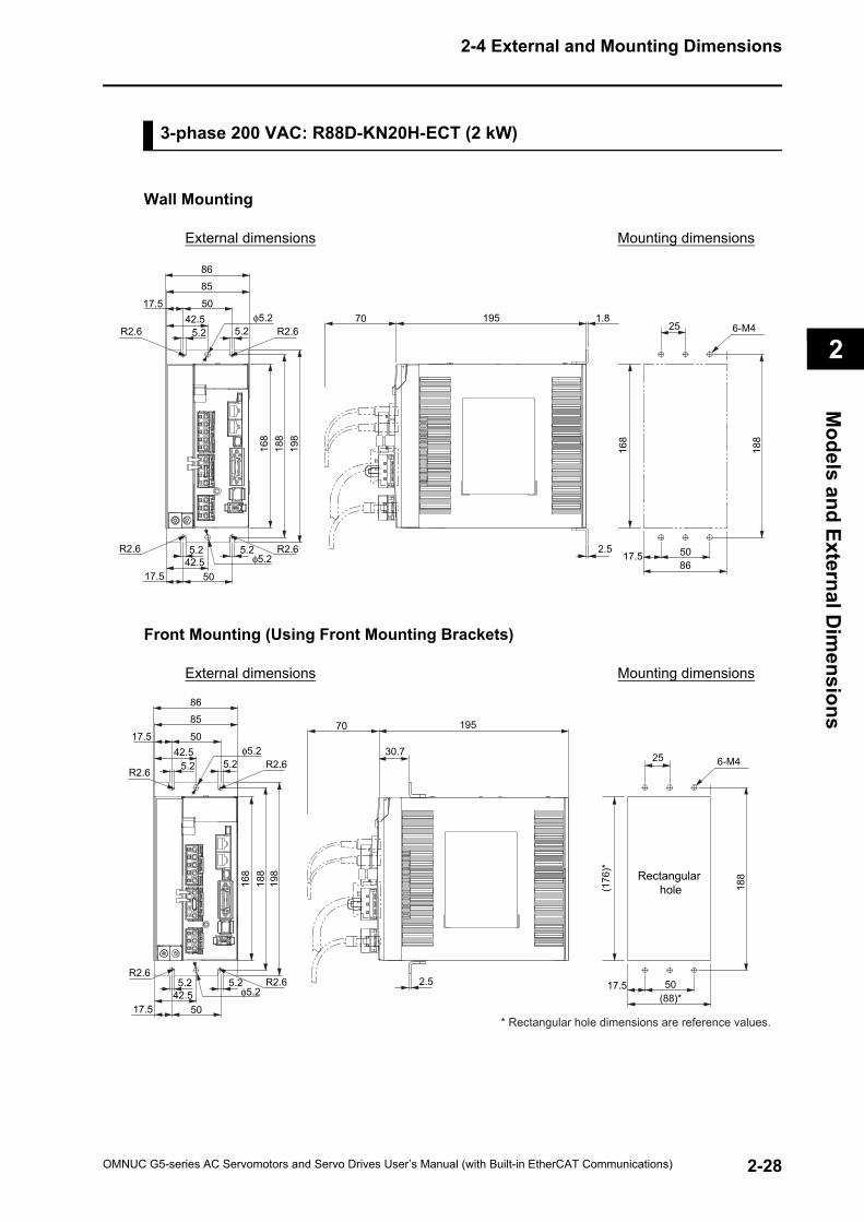
2-4 External and Mounting Dimensions
2
Models and External D
imensions
3-phase 200 VAC: R88D-KN20H-ECT (2 kW)
Wall Mounting
External dimensions Mounting dimensions
Front Mounting (Using Front Mounting Brackets)
External dimensions Mounting dimensions
86
85
5017.542.5
5.2 5.2φ5.2
R2.6 R2.619570
198
188
168
17.5 50
5.25.242.5 φ5.2
R2.6 R2.6
1.825
188
5017.5
6-M4
168
862.5
86
85
5017.542.5
5.2 5.2
198
188
168
φ5.2
R2.6R2.6
195
30.7
70
17.5 50
5.25.242.5 φ5.2
R2.6R2.6 2.5
25
188
5017.5
6-M4
(88)*
(176
)*
* Rectangular hole dimensions are reference values.
Rectangular hole
2-28OMNUC G5-series AC Servomotors and Servo Drives User’s Manual (with Built-in EtherCAT Communications)
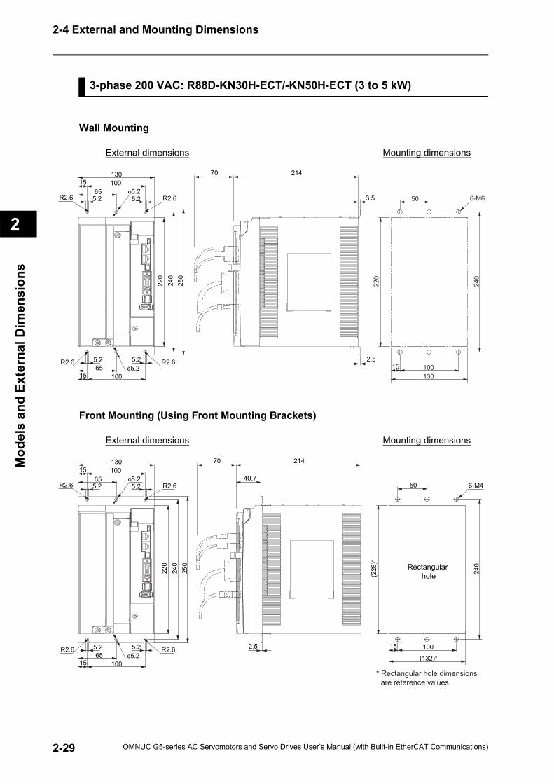
2-4 External and Mounting Dimensions
2
Mod
els
and
Exte
rnal
Dim
ensi
ons
3-phase 200 VAC: R88D-KN30H-ECT/-KN50H-ECT (3 to 5 kW)
Wall Mounting
External dimensions Mounting dimensions
Front Mounting (Using Front Mounting Brackets)
External dimensions Mounting dimensions
R2.6R2.6φ5.2
R2.6R2.6φ5.2
13010015
655.2 5.2
220
240
250
5.2 5.265
10015
21470
3.5 6-M650
240
100130
1522
0
2.5
R2.6R2.6φ5.2
R2.6R2.6φ5.2
13010015
655.2 5.2
220
240
250
5.2 5.265
10015
214
40.7
2.5
70
6-M45024
0
100
(132)*
15
(228
)*
Rectangular hole
* Rectangular hole dimensions are reference values.
2-29 OMNUC G5-series AC Servomotors and Servo Drives User’s Manual (with Built-in EtherCAT Communications)
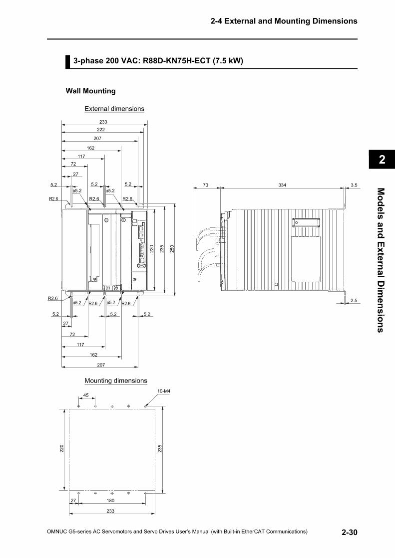
2-4 External and Mounting Dimensions
2
Models and External D
imensions
3-phase 200 VAC: R88D-KN75H-ECT (7.5 kW)
Wall Mounting
External dimensions
Mounting dimensions
334 3.5
2.5
70
27
72117
162
207
222233
5.2 5.2 5.2
R2.6 R2.6 R2.6
φ5.2 φ5.2
220
235
250
5.2 5.2 5.2
72
117
162
207
R2.6
27
R2.6φ5.2 φ5.2 R2.6
10-M4
235
45
220
27 180
233
2-30OMNUC G5-series AC Servomotors and Servo Drives User’s Manual (with Built-in EtherCAT Communications)
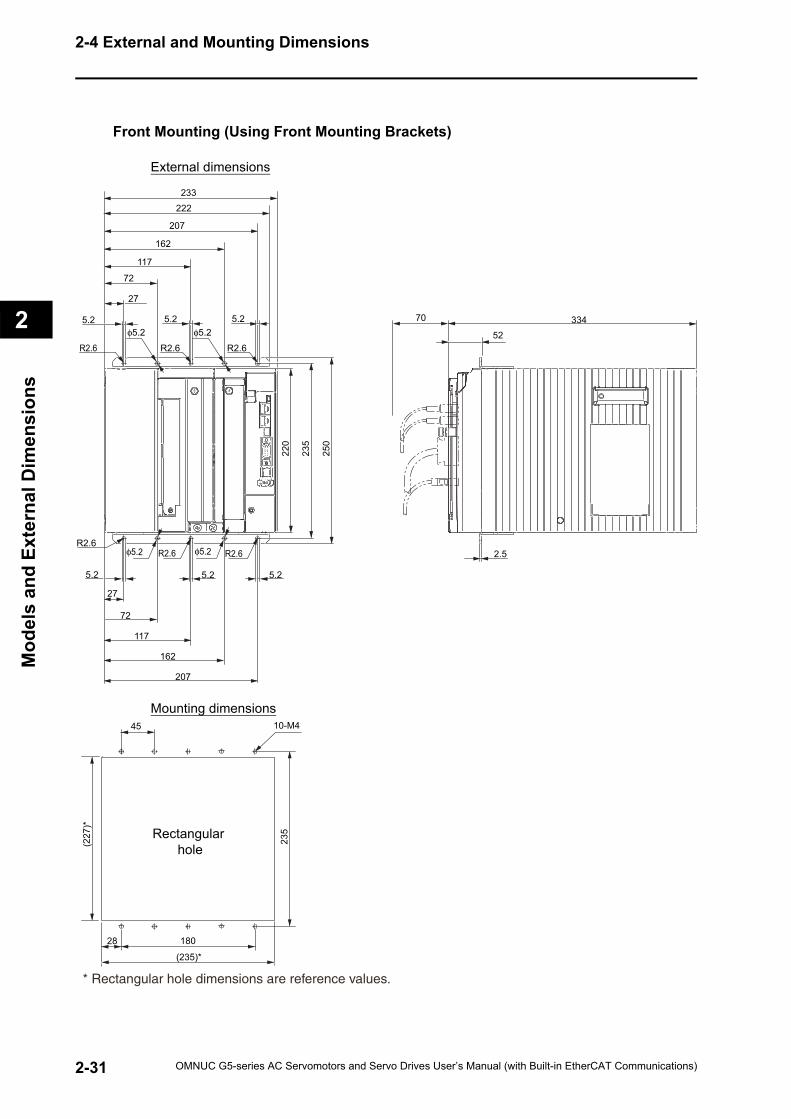
2-4 External and Mounting Dimensions
2
Mod
els
and
Exte
rnal
Dim
ensi
ons
Front Mounting (Using Front Mounting Brackets)
External dimensions
Mounting dimensions
27
72
117
162
207
222233
5.2 5.2 5.2
220
235
250
5.2 5.2 5.2
72
117
162
207
R2.6
27
R2.6φ5.2 φ5.2 R2.6
R2.6 R2.6 R2.6
φ5.2 φ5.233470
2.5
52
10-M4
235
45
(227
)*
28 180
(235)*
Rectangular hole
* Rectangular hole dimensions are reference values.
2-31 OMNUC G5-series AC Servomotors and Servo Drives User’s Manual (with Built-in EtherCAT Communications)
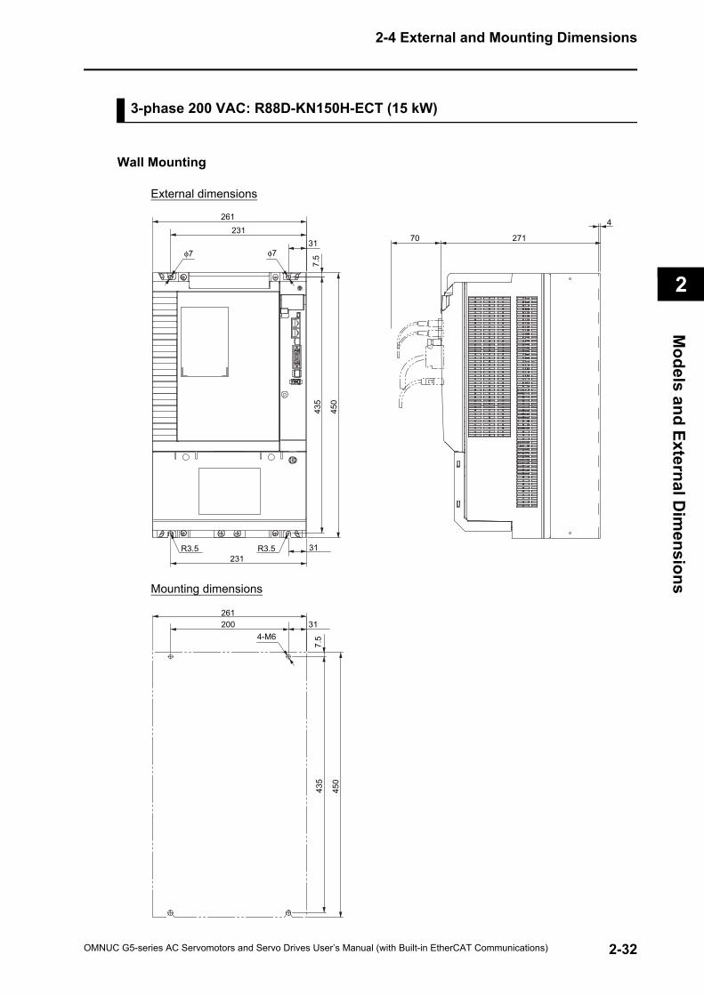
2-4 External and Mounting Dimensions
2
Models and External D
imensions
3-phase 200 VAC: R88D-KN150H-ECT (15 kW)
Wall Mounting
External dimensions
Mounting dimensions
261231
31
450
7.5
435
31231
4
271
R3.5 R3.5
φ7φ7
70
450
435
261200 31
7.54-M6
2-32OMNUC G5-series AC Servomotors and Servo Drives User’s Manual (with Built-in EtherCAT Communications)
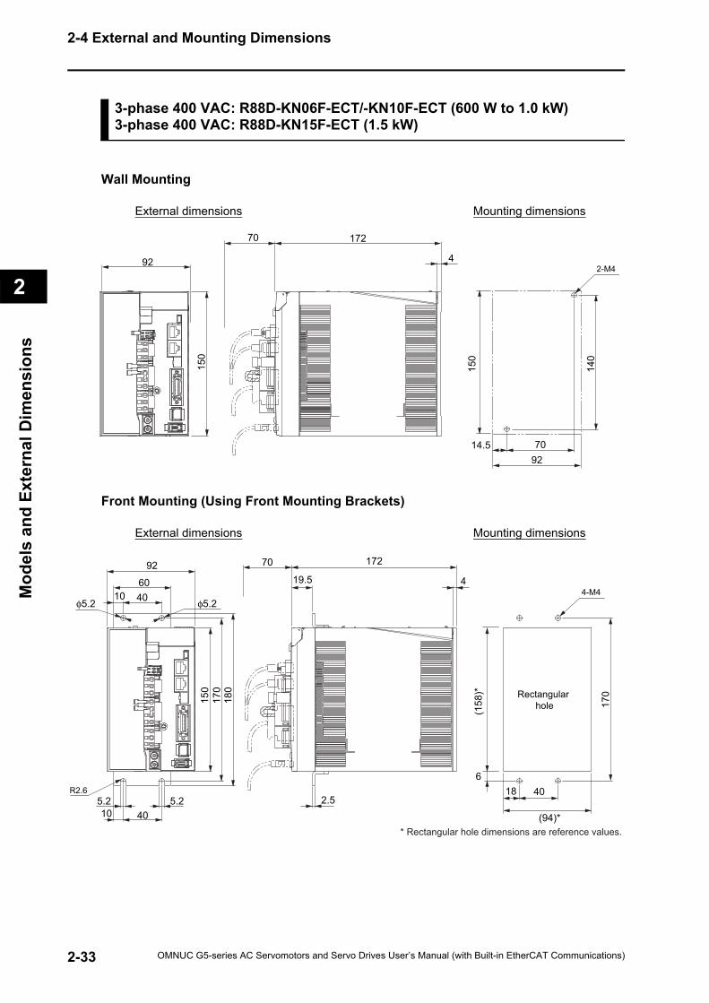
2-4 External and Mounting Dimensions
2
Mod
els
and
Exte
rnal
Dim
ensi
ons
3-phase 400 VAC: R88D-KN06F-ECT/-KN10F-ECT (600 W to 1.0 kW) 3-phase 400 VAC: R88D-KN15F-ECT (1.5 kW)
Wall Mounting
External dimensions Mounting dimensions
Front Mounting (Using Front Mounting Brackets)
External dimensions Mounting dimensions
92
150
172
4
150
140
7014.5
70
2-M4
92
92
604010
φ5.2 φ5.2
170
180
150
5.2 5.210 40
R2.6
17270
419.5
2.54018
6
(94)*
170
(158
)*
4-M4
* Rectangular hole dimensions are reference values.
Rectangular hole
2-33 OMNUC G5-series AC Servomotors and Servo Drives User’s Manual (with Built-in EtherCAT Communications)
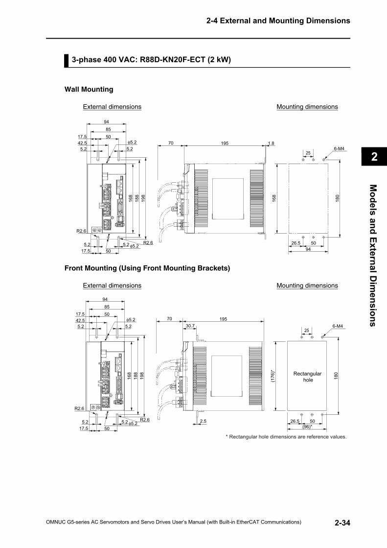
2-4 External and Mounting Dimensions
2
Models and External D
imensions
3-phase 400 VAC: R88D-KN20F-ECT (2 kW)
Wall Mounting
External dimensions Mounting dimensions
Front Mounting (Using Front Mounting Brackets)
External dimensions Mounting dimensions
φ5.2
R2.6
R2.6φ5.2
25
180
5094
168
195 1.8
94855017.5
42.55.2 5.2
5.2 5.25017.5
168
188
198
706-M4
26.5
φ5.2
R2.6
R2.6φ5.2
2518
0
50(96)*
(176
)*
195
94855017.5
42.55.2 5.2
5.2 5.25017.5
168
188
198
706-M4
26.52.5
30.7
* Rectangular hole dimensions are reference values.
Rectangular hole
2-34OMNUC G5-series AC Servomotors and Servo Drives User’s Manual (with Built-in EtherCAT Communications)
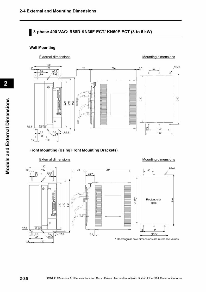
2-4 External and Mounting Dimensions
2
Mod
els
and
Exte
rnal
Dim
ensi
ons
3-phase 400 VAC: R88D-KN30F-ECT/-KN50F-ECT (3 to 5 kW)
Wall Mounting
External dimensions Mounting dimensions
Front Mounting (Using Front Mounting Brackets)
External dimensions Mounting dimensions
φ5.2
R2.6φ5.2
R2.6
100
5.25.265
15
15130100
655.2 5.2
220
240
250
50
240
220
13010015
214 3.5706-M4
φ5.2
R2.6φ5.2
R2.6
100
5.25.265
15
15130100
655.2 5.2
220
240
250
5024
0
(228
)*
(132)*10015
214706-M4
2.5
40.7
* Rectangular hole dimensions are reference values.
Rectangular hole
2-35 OMNUC G5-series AC Servomotors and Servo Drives User’s Manual (with Built-in EtherCAT Communications)
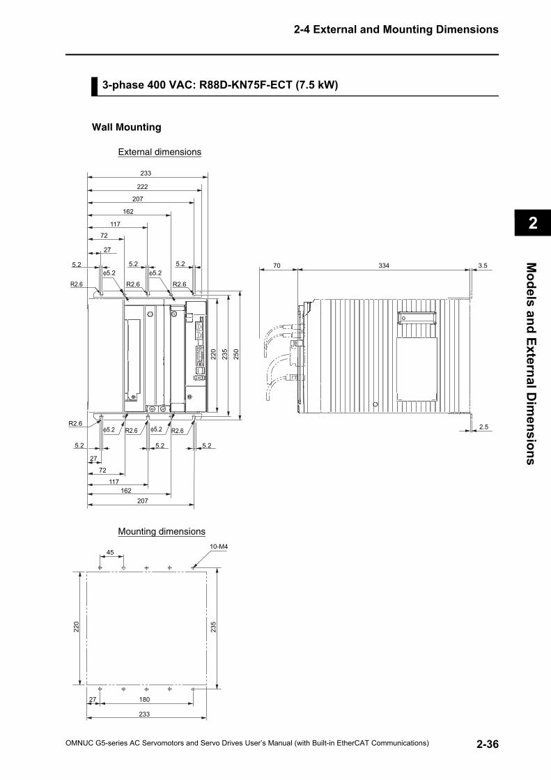
2-4 External and Mounting Dimensions
2
Models and External D
imensions
3-phase 400 VAC: R88D-KN75F-ECT (7.5 kW)
Wall Mounting
External dimensions
Mounting dimensions
334 3.5
2.5
70
27
72
117
162
207
222
233
5.2 5.2 5.2
R2.6 R2.6 R2.6
φ5.2 φ5.2
220
235
250
5.2 5.2 5.2
72
117162
207
R2.6
27
R2.6φ5.2 φ5.2 R2.6
10-M4
235
45
220
27 180
233
2-36OMNUC G5-series AC Servomotors and Servo Drives User’s Manual (with Built-in EtherCAT Communications)
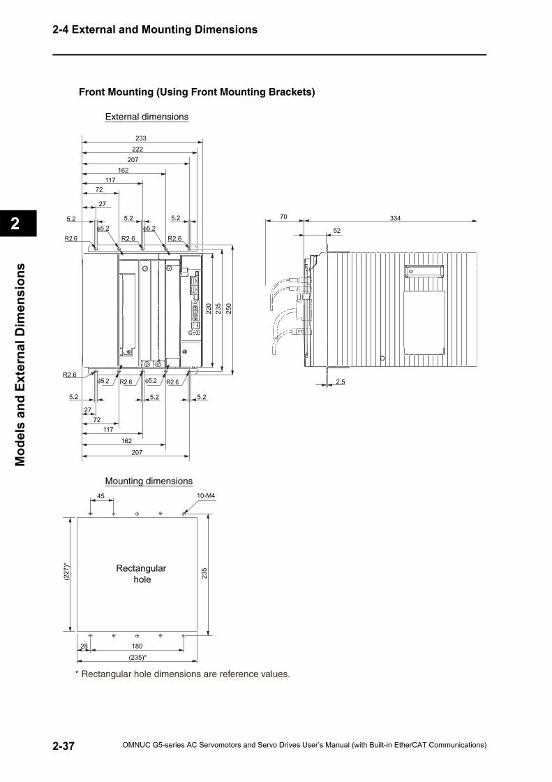
2-4 External and Mounting Dimensions
2
Mod
els
and
Exte
rnal
Dim
ensi
ons
Front Mounting (Using Front Mounting Brackets)
External dimensions
Mounting dimensions
27
72117
162207
222233
5.2 5.2 5.222
023
525
0
5.2 5.2 5.2
72117
162
207
R2.6
27
R2.6φ5.2 φ5.2 R2.6
R2.6 R2.6 R2.6φ5.2 φ5.2
33470
2.5
52
10-M4
235
45
(227
)*
28 180
(235)*
Rectangular hole
* Rectangular hole dimensions are reference values.
2-37 OMNUC G5-series AC Servomotors and Servo Drives User’s Manual (with Built-in EtherCAT Communications)
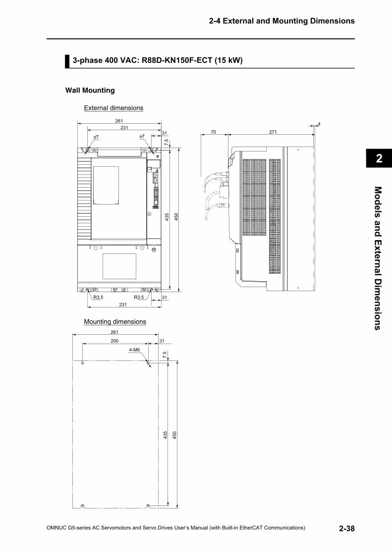
2-4 External and Mounting Dimensions
2
Models and External D
imensions
3-phase 400 VAC: R88D-KN150F-ECT (15 kW)
Wall Mounting
External dimensions
Mounting dimensions
261231
31
450
7.5
435
31231
4
271
R3.5 R3.5
φ7φ770
450
435
261
200 31
7.54-M6
2-38OMNUC G5-series AC Servomotors and Servo Drives User’s Manual (with Built-in EtherCAT Communications)
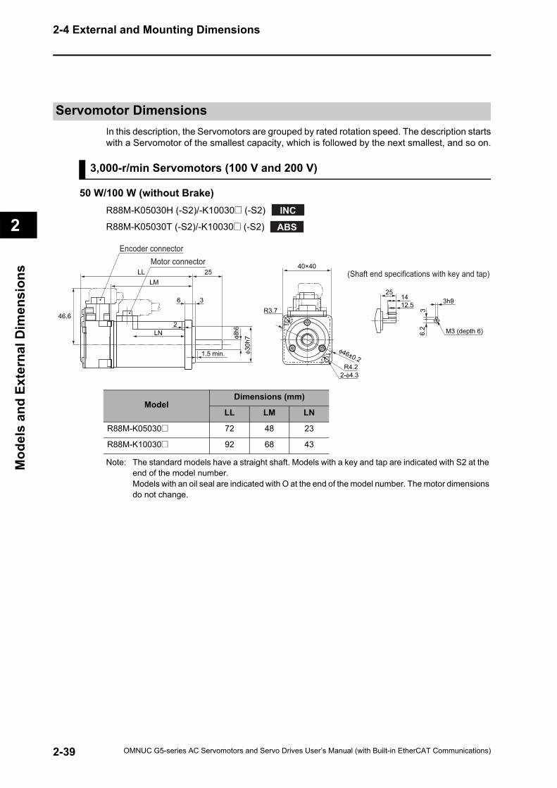
2-4 External and Mounting Dimensions
2
Mod
els
and
Exte
rnal
Dim
ensi
ons
Servomotor DimensionsIn this description, the Servomotors are grouped by rated rotation speed. The description startswith a Servomotor of the smallest capacity, which is followed by the next smallest, and so on.
3,000-r/min Servomotors (100 V and 200 V)
50 W/100 W (without Brake)R88M-K05030H (-S2)/-K10030@ (-S2)
R88M-K05030T (-S2)/-K10030@ (-S2)
Note: The standard models have a straight shaft. Models with a key and tap are indicated with S2 at the end of the model number.Models with an oil seal are indicated with O at the end of the model number. The motor dimensions do not change.
INC
ABS
M3 (depth 6)
φ8h6
φ30h
7
251412.5 3h9
36.
2
25LLLM
6 3
1.5 min.
2LN
R3.7
R4.22-φ4.3
φ46±0.2
40×40(Shaft end specifications with key and tap)
Encoder connectorMotor connector
46.6
ModelDimensions (mm)
LL LM LN
R88M-K05030@ 72 48 23
R88M-K10030@ 92 68 43
2-39 OMNUC G5-series AC Servomotors and Servo Drives User’s Manual (with Built-in EtherCAT Communications)
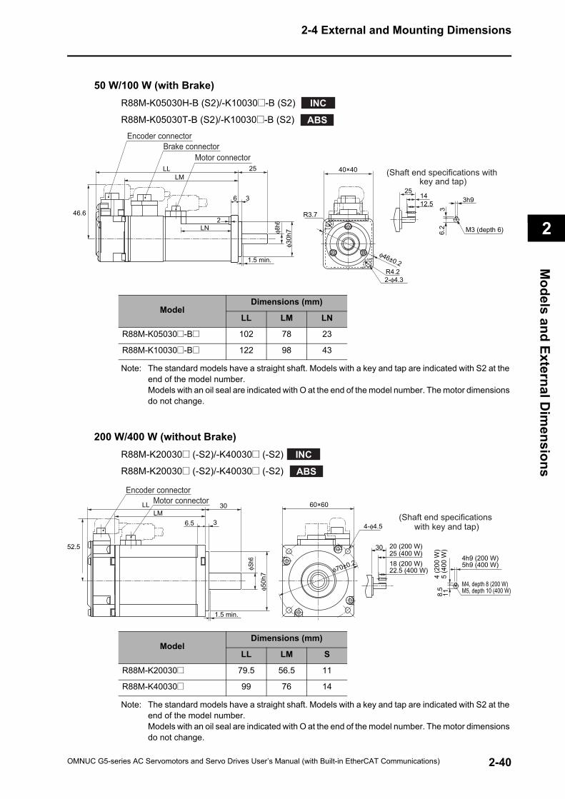
2-4 External and Mounting Dimensions
2
Models and External D
imensions
50 W/100 W (with Brake)R88M-K05030H-B (S2)/-K10030@-B (S2)
R88M-K05030T-B (S2)/-K10030@-B (S2)
Note: The standard models have a straight shaft. Models with a key and tap are indicated with S2 at the end of the model number.Models with an oil seal are indicated with O at the end of the model number. The motor dimensions do not change.
200 W/400 W (without Brake)R88M-K20030@ (-S2)/-K40030@ (-S2)
R88M-K20030@ (-S2)/-K40030@ (-S2)
Note: The standard models have a straight shaft. Models with a key and tap are indicated with S2 at the end of the model number.Models with an oil seal are indicated with O at the end of the model number. The motor dimensions do not change.
INC
ABS
M3 (depth 6)
251412.5 3h9
36.
2
R3.7
R4.22-φ4.3
φ46±0.2
40×40LLLM
Motor connector
φ8h6
φ30h
7
25
36
2
1.5 min.
LN
(Shaft end specifications with key and tap)
Brake connectorEncoder connector
46.6
ModelDimensions (mm)
LL LM LN
R88M-K05030@-B@ 102 78 23
R88M-K10030@-B@ 122 98 43
INC
ABS
φSh6
φ50h
7
30 20 (200 W)25 (400 W)
22.5 (400 W)
5 (4
00 W
)4
(200
W)
8.5
11
LLLM
30
36.5
φ70±0.2
60×60
(Shaft end specifications with key and tap)
1.5 min.
4h9 (200 W)5h9 (400 W)
M4, depth 8 (200 W) M5, depth 10 (400 W)
18 (200 W)
4-φ4.5
Motor connectorEncoder connector
52.5
ModelDimensions (mm)
LL LM S
R88M-K20030@ 79.5 56.5 11
R88M-K40030@ 99 76 14
2-40OMNUC G5-series AC Servomotors and Servo Drives User’s Manual (with Built-in EtherCAT Communications)
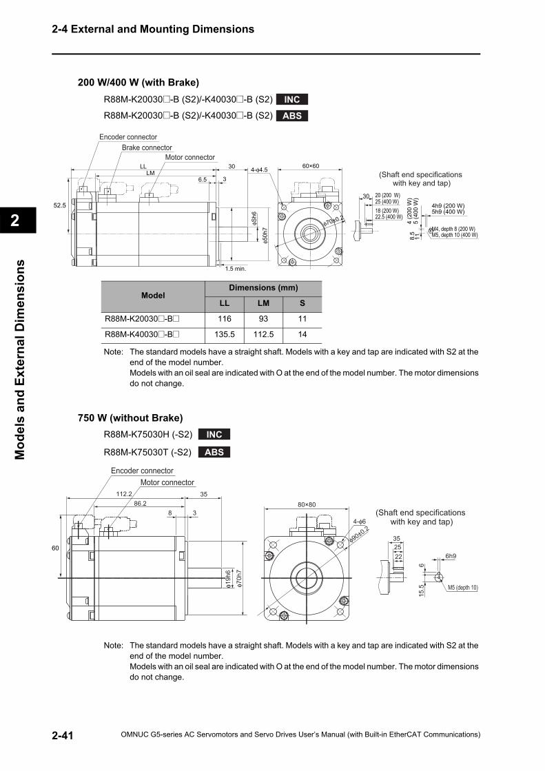
2-4 External and Mounting Dimensions
2
Mod
els
and
Exte
rnal
Dim
ensi
ons
200 W/400 W (with Brake)R88M-K20030@-B (S2)/-K40030@-B (S2)
R88M-K20030@-B (S2)/-K40030@-B (S2)
Note: The standard models have a straight shaft. Models with a key and tap are indicated with S2 at the end of the model number.Models with an oil seal are indicated with O at the end of the model number. The motor dimensions do not change.
750 W (without Brake)R88M-K75030H (-S2)
R88M-K75030T (-S2)
Note: The standard models have a straight shaft. Models with a key and tap are indicated with S2 at the end of the model number.Models with an oil seal are indicated with O at the end of the model number. The motor dimensions do not change.
INC
ABS
30 20 (200 W)25 (400 W)
22.5 (400 W)
5 (4
00 W
)4
(200
W)
8.5
11
φ70±0.2
60×60(Shaft end specifications
with key and tap)
1.5 min.
6.5 3
LLLM
30
4h9 (200 W)5h9 (400 W)
M4, depth 8 (200 W) M5, depth 10 (400 W)
18 (200 W)
φSh6
φ50h
7
4-φ4.5
Brake connectorEncoder connector
Motor connector
52.5
ModelDimensions (mm)
LL LM S
R88M-K20030@-B@ 116 93 11
R88M-K40030@-B@ 135.5 112.5 14
INC
ABS
(Shaft end specifications with key and tap)
352522 6h9
15.5
6
112.2 3586.2
8 3
φ19h
6
φ70h
7
Motor connectorEncoder connector
80×80
4-φ6
φ90±0.2
M5 (depth 10)
60
2-41 OMNUC G5-series AC Servomotors and Servo Drives User’s Manual (with Built-in EtherCAT Communications)
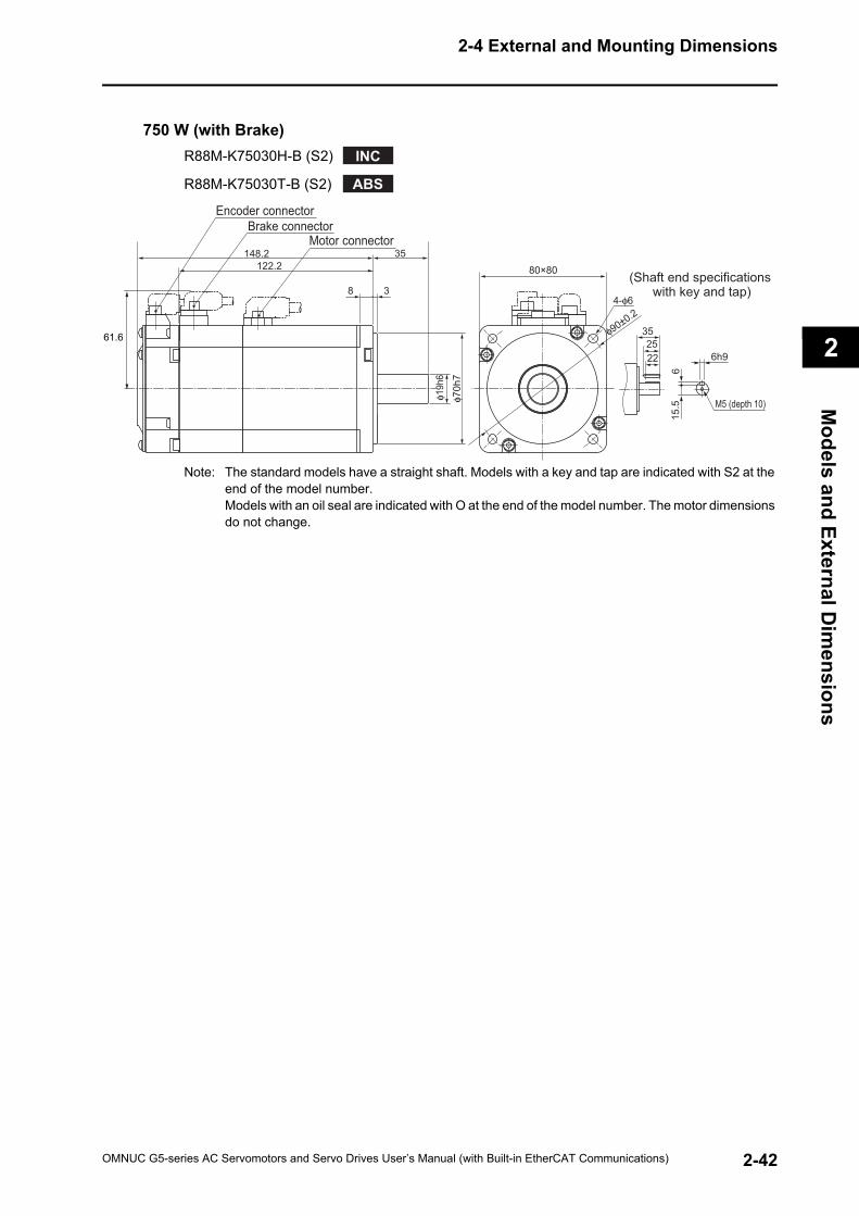
2-4 External and Mounting Dimensions
2
Models and External D
imensions
750 W (with Brake)R88M-K75030H-B (S2)
R88M-K75030T-B (S2)
Note: The standard models have a straight shaft. Models with a key and tap are indicated with S2 at the end of the model number.Models with an oil seal are indicated with O at the end of the model number. The motor dimensions do not change.
INC
ABS
Motor connectorBrake connector
Encoder connector
(Shaft end specifications with key and tap)
148.2 35122.2
352522
8 3
φ19h
6
φ70h
7
4-φ6
80×80
φ90±0.2
M5 (depth 10)
6h9
15.5
6
61.6
2-42OMNUC G5-series AC Servomotors and Servo Drives User’s Manual (with Built-in EtherCAT Communications)
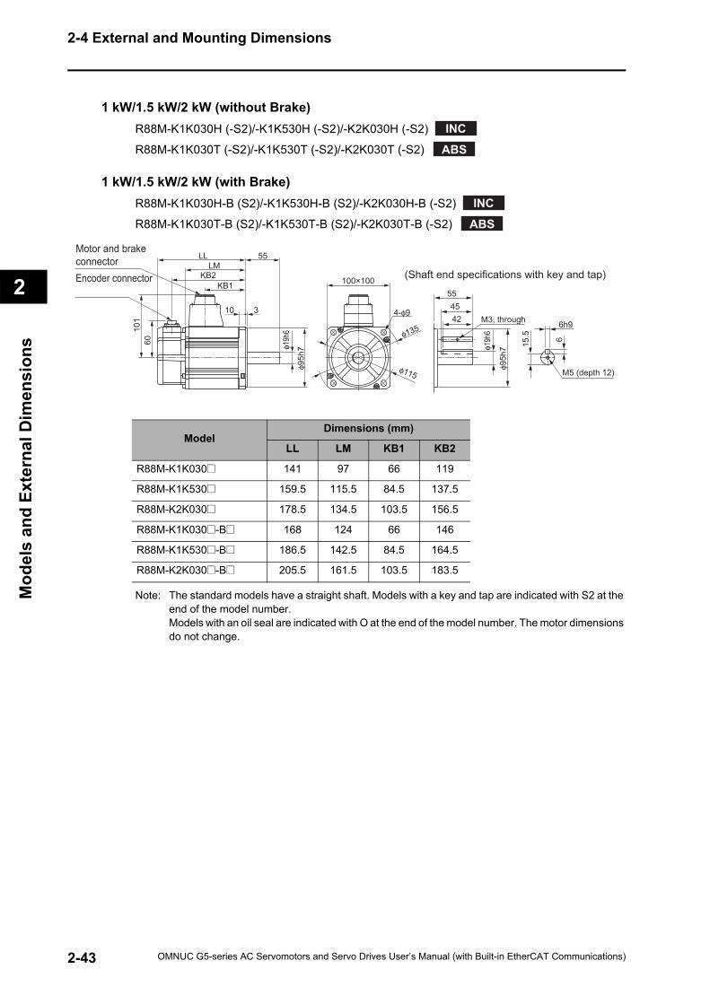
2-4 External and Mounting Dimensions
2
Mod
els
and
Exte
rnal
Dim
ensi
ons
1 kW/1.5 kW/2 kW (without Brake)R88M-K1K030H (-S2)/-K1K530H (-S2)/-K2K030H (-S2)
R88M-K1K030T (-S2)/-K1K530T (-S2)/-K2K030T (-S2)
1 kW/1.5 kW/2 kW (with Brake)R88M-K1K030H-B (S2)/-K1K530H-B (S2)/-K2K030H-B (-S2)
R88M-K1K030T-B (S2)/-K1K530T-B (S2)/-K2K030T-B (-S2)
Note: The standard models have a straight shaft. Models with a key and tap are indicated with S2 at the end of the model number.Models with an oil seal are indicated with O at the end of the model number. The motor dimensions do not change.
ModelDimensions (mm)
LL LM KB1 KB2
R88M-K1K030@ 141 97 66 119
R88M-K1K530@ 159.5 115.5 84.5 137.5
R88M-K2K030@ 178.5 134.5 103.5 156.5
R88M-K1K030@-B@ 168 124 66 146
R88M-K1K530@-B@ 186.5 142.5 84.5 164.5
R88M-K2K030@-B@ 205.5 161.5 103.5 183.5
INC
ABS
INC
ABS
LMKB2
KB1
55LL
3
101
60
10
φ19h
6
φ95h
7
φ115
4-φ94245
55
φ135
100×100Encoder connector
Motor and brakeconnector
M3, through 6h9
φ19h
6
615.5
φ95h
7
M5 (depth 12)
(Shaft end specifications with key and tap)
2-43 OMNUC G5-series AC Servomotors and Servo Drives User’s Manual (with Built-in EtherCAT Communications)
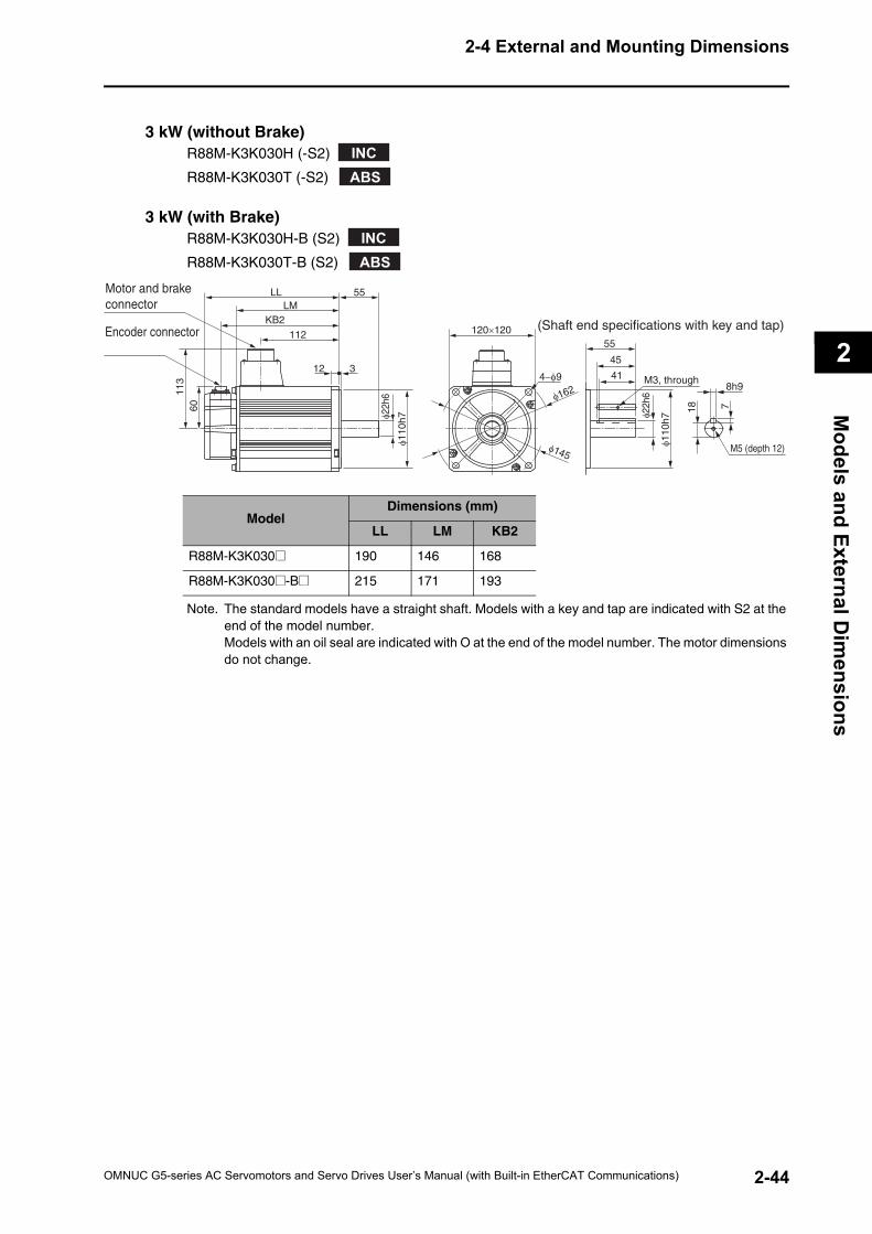
2-4 External and Mounting Dimensions
2
Models and External D
imensions
3 kW (without Brake)R88M-K3K030H (-S2)
R88M-K3K030T (-S2)
3 kW (with Brake)R88M-K3K030H-B (S2)
R88M-K3K030T-B (S2)
Note. The standard models have a straight shaft. Models with a key and tap are indicated with S2 at the end of the model number.Models with an oil seal are indicated with O at the end of the model number. The motor dimensions do not change.
INCABS
INCABS
Encoder connector
Motor and brakeconnector LM
KB2112
55LL
113
60
312
φ22h
6
φ110
h7
120×120
4−φ9
φ145
φ162
41
45
55
M3, through
M5 (depth 12)
φ22h
6
φ110
h7
8h9
718
(Shaft end specifications with key and tap)
ModelDimensions (mm)
LL LM KB2
R88M-K3K030@ 190 146 168
R88M-K3K030@-B@ 215 171 193
2-44OMNUC G5-series AC Servomotors and Servo Drives User’s Manual (with Built-in EtherCAT Communications)
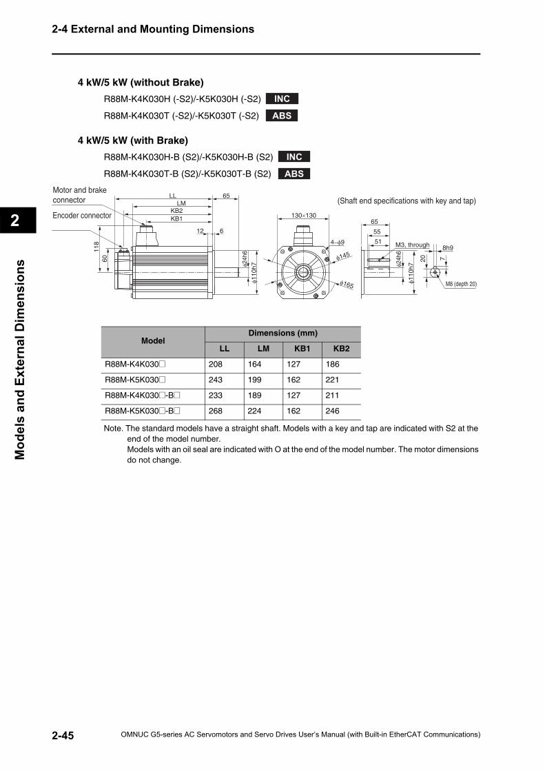
2-4 External and Mounting Dimensions
2
Mod
els
and
Exte
rnal
Dim
ensi
ons
4 kW/5 kW (without Brake)
R88M-K4K030H (-S2)/-K5K030H (-S2)
R88M-K4K030T (-S2)/-K5K030T (-S2)
4 kW/5 kW (with Brake)
R88M-K4K030H-B (S2)/-K5K030H-B (S2)
R88M-K4K030T-B (S2)/-K5K030T-B (S2)
Note. The standard models have a straight shaft. Models with a key and tap are indicated with S2 at the end of the model number.Models with an oil seal are indicated with O at the end of the model number. The motor dimensions do not change.
INC
ABS
INC
ABS
Encoder connector
Motor and brakeconnector LM
KB2KB1
65LL
118
60
612
φ24h
6φ1
10h7
130×130
4−φ9
φ165
φ145
51
55
65
M3, through
M8 (depth 20)
φ24h
6
φ110
h7
8h9
720
(Shaft end specifications with key and tap)
ModelDimensions (mm)
LL LM KB1 KB2
R88M-K4K030@ 208 164 127 186
R88M-K5K030@ 243 199 162 221
R88M-K4K030@-B@ 233 189 127 211
R88M-K5K030@-B@ 268 224 162 246
2-45 OMNUC G5-series AC Servomotors and Servo Drives User’s Manual (with Built-in EtherCAT Communications)
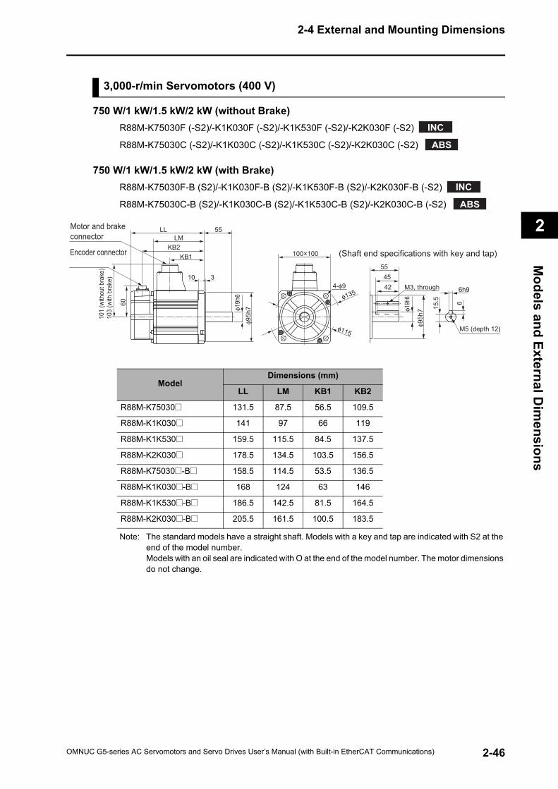
2-4 External and Mounting Dimensions
2
Models and External D
imensions
3,000-r/min Servomotors (400 V)
750 W/1 kW/1.5 kW/2 kW (without Brake)R88M-K75030F (-S2)/-K1K030F (-S2)/-K1K530F (-S2)/-K2K030F (-S2)
R88M-K75030C (-S2)/-K1K030C (-S2)/-K1K530C (-S2)/-K2K030C (-S2)
750 W/1 kW/1.5 kW/2 kW (with Brake)R88M-K75030F-B (S2)/-K1K030F-B (S2)/-K1K530F-B (S2)/-K2K030F-B (-S2)
R88M-K75030C-B (S2)/-K1K030C-B (S2)/-K1K530C-B (S2)/-K2K030C-B (-S2)
Note: The standard models have a straight shaft. Models with a key and tap are indicated with S2 at the end of the model number.Models with an oil seal are indicated with O at the end of the model number. The motor dimensions do not change.
INC
ABS
INC
ABS
Encoder connector
Motor and brakeconnector LM
KB2KB1
55LL
101
(with
out b
rake
) 10
3 (w
ith b
rake
)
60
310
φ19h
6φ9
5h7
100×100
4-φ9
φ115
φ1354245
55
M3, through
M5 (depth 12)
φ19h
6
φ95h
7
6h9
6
15.5
(Shaft end specifications with key and tap)
ModelDimensions (mm)
LL LM KB1 KB2
R88M-K75030@ 131.5 87.5 56.5 109.5
R88M-K1K030@ 141 97 66 119
R88M-K1K530@ 159.5 115.5 84.5 137.5
R88M-K2K030@ 178.5 134.5 103.5 156.5
R88M-K75030@-B@ 158.5 114.5 53.5 136.5
R88M-K1K030@-B@ 168 124 63 146
R88M-K1K530@-B@ 186.5 142.5 81.5 164.5
R88M-K2K030@-B@ 205.5 161.5 100.5 183.5
2-46OMNUC G5-series AC Servomotors and Servo Drives User’s Manual (with Built-in EtherCAT Communications)
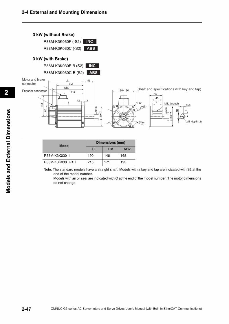
2-4 External and Mounting Dimensions
2
Mod
els
and
Exte
rnal
Dim
ensi
ons
3 kW (without Brake)
R88M-K3K030F (-S2)
R88M-K3K030C (-S2)
3 kW (with Brake)
R88M-K3K030F-B (S2)
R88M-K3K030C-B (S2)
0
Note. The standard models have a straight shaft. Models with a key and tap are indicated with S2 at the end of the model number.Models with an oil seal are indicated with O at the end of the model number. The motor dimensions do not change.
INC
ABS
INC
ABS
Encoder connector
Motor and brakeconnector LM
KB2112
55LL
113
60
312
φ22h
6
φ110
h7
120×120
4-φ9
φ145
φ162
41
45
55
M3, through
M5 (depth 12)
φ22h
6
φ110
h7
8h9
718
(Shaft end specifications with key and tap)
ModelDimensions (mm)
LL LM KB2
R88M-K3K030@ 190 146 168
R88M-K3K030@-B@ 215 171 193
2-47 OMNUC G5-series AC Servomotors and Servo Drives User’s Manual (with Built-in EtherCAT Communications)
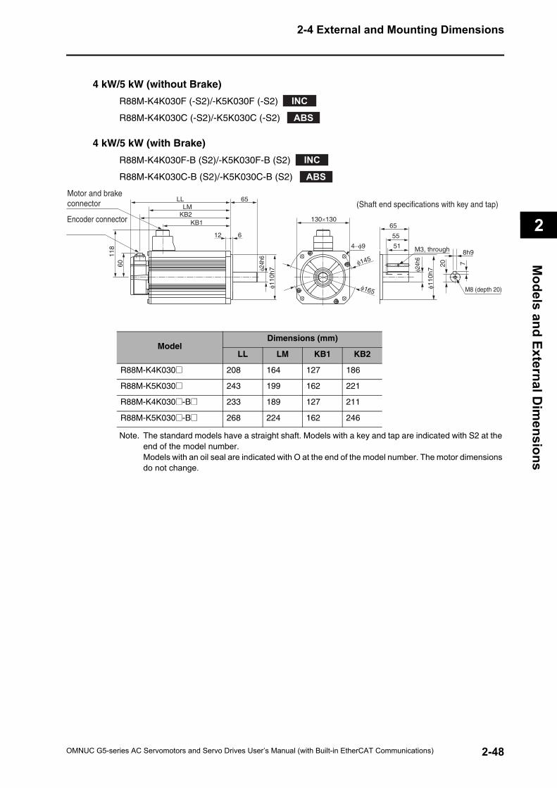
2-4 External and Mounting Dimensions
2
Models and External D
imensions
4 kW/5 kW (without Brake)
R88M-K4K030F (-S2)/-K5K030F (-S2)
R88M-K4K030C (-S2)/-K5K030C (-S2)
4 kW/5 kW (with Brake)
R88M-K4K030F-B (S2)/-K5K030F-B (S2)
R88M-K4K030C-B (S2)/-K5K030C-B (S2)
Note. The standard models have a straight shaft. Models with a key and tap are indicated with S2 at the end of the model number.Models with an oil seal are indicated with O at the end of the model number. The motor dimensions do not change.
INC
ABS
INC
ABS
Encoder connector
Motor and brakeconnector LM
KB2KB1
65LL
118
60
612
φ24h
6
φ110
h7
130×130
4−φ9
φ165
φ145
51
55
65
M3, through
M8 (depth 20)
φ24h
6
φ110
h7
8h9
720
(Shaft end specifications with key and tap)
ModelDimensions (mm)
LL LM KB1 KB2
R88M-K4K030@ 208 164 127 186
R88M-K5K030@ 243 199 162 221
R88M-K4K030@-B@ 233 189 127 211
R88M-K5K030@-B@ 268 224 162 246
2-48OMNUC G5-series AC Servomotors and Servo Drives User’s Manual (with Built-in EtherCAT Communications)
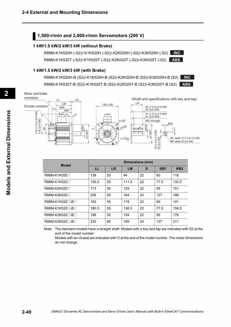
2-4 External and Mounting Dimensions
2
Mod
els
and
Exte
rnal
Dim
ensi
ons
1,500-r/min and 2,000-r/min Servomotors (200 V)
1 kW/1.5 kW/2 kW/3 kW (without Brake)R88M-K1K020H (-S2)/-K1K520H (-S2)/-K2K020H (-S2)/-K3K020H (-S2)
R88M-K1K020T (-S2)/-K1K520T (-S2)/-K2K020T (-S2)/-K3K020T (-S2)
1 kW/1.5 kW/2 kW/3 kW (with Brake)R88M-K1K020H-B (S2)/-K1K520H-B (S2)/-K2K020H-B (S2)/-K3K020H-B (S2)
R88M-K1K020T-B (S2)/-K1K520T-B (S2)/-K2K020T-B (S2)/-K3K020T-B (S2)
Note: The standard models have a straight shaft. Models with a key and tap are indicated with S2 at the end of the model number.Models with an oil seal are indicated with O at the end of the model number. The motor dimensions do not change.
ModelDimensions (mm)
LL LR LM S KB1 KB2
R88M-K1K020@ 138 55 94 22 60 116
R88M-K1K520@ 155.5 55 111.5 22 77.5 133.5
R88M-K2K020@ 173 55 129 22 95 151
R88M-K3K020@ 208 65 164 24 127 186
R88M-K1K020@-B@ 163 55 119 22 60 141
R88M-K1K520@-B@ 180.5 55 136.5 22 77.5 158.5
R88M-K2K020@-B@ 198 55 154 22 95 176
R88M-K3K020@-B@ 233 65 189 24 127 211
INC
ABS
INC
ABS
Encoder connector
Motor and brakeconnector
LMKB2
KB1
LRLL
116
(1.0
to 2
.0 k
W)
118
(3.0
kW
)
60
130×13045 (1.0 to 2.0 kW)55 (3.0 kW)
41 (1.0 to 2.0 kW)51 (3.0 kW)
LR
M3, through
M5, depth 12 (1.0 to 2.0 kW)M8, depth 20 (3.0 kW)
8h9
7
18 (1
.0 to
2.0
kW
)20
(3.0
kW
)
(Shaft end specifications with key and tap)
612
φSh6
φSh6
φ110
h7
4−φ9
φ165
φ145
φ110
h7
2-49 OMNUC G5-series AC Servomotors and Servo Drives User’s Manual (with Built-in EtherCAT Communications)
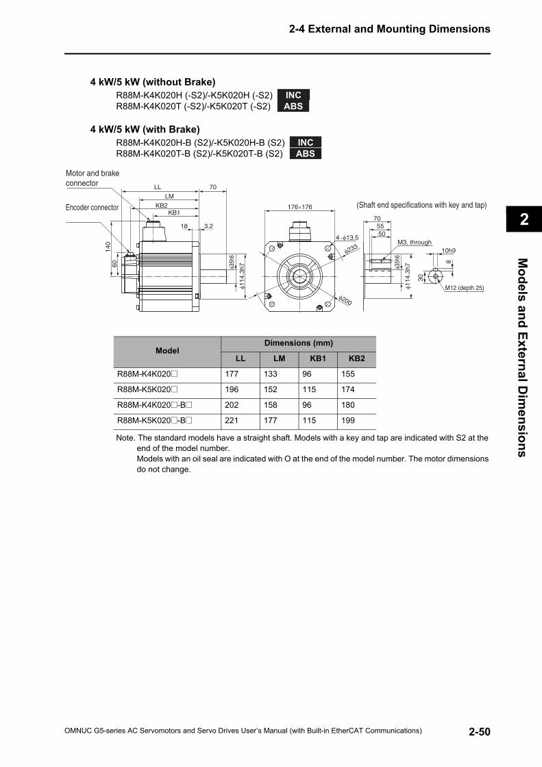
2-4 External and Mounting Dimensions
2
Models and External D
imensions
4 kW/5 kW (without Brake)R88M-K4K020H (-S2)/-K5K020H (-S2) R88M-K4K020T (-S2)/-K5K020T (-S2)
4 kW/5 kW (with Brake)R88M-K4K020H-B (S2)/-K5K020H-B (S2) R88M-K4K020T-B (S2)/-K5K020T-B (S2)
Note. The standard models have a straight shaft. Models with a key and tap are indicated with S2 at the end of the model number.Models with an oil seal are indicated with O at the end of the model number. The motor dimensions do not change.
ModelDimensions (mm)
LL LM KB1 KB2
R88M-K4K020@ 177 133 96 155
R88M-K5K020@ 196 152 115 174
R88M-K4K020@-B@ 202 158 96 180
R88M-K5K020@-B@ 221 177 115 199
INCABS
INCABS
Encoder connector
Motor and brakeconnector
LMKB2
KB1
70LL
140
60
176×176
705550
M3, through
(Shaft end specifications with key and tap)
3.218
φ114
.3h7
4−φ13.5
φ200
φ233
φ35h
6
φ35h
6
φ114
.3h7
M12 (depth 25)
10h9
8
30
2-50OMNUC G5-series AC Servomotors and Servo Drives User’s Manual (with Built-in EtherCAT Communications)

2-4 External and Mounting Dimensions
2
Mod
els
and
Exte
rnal
Dim
ensi
ons
7.5 kW (without Brake)
R88M-K7K515T (-S2)
7.5 kW (with Brake)
R88M-K7K515T-B (S2)
Note. The standard models have a straight shaft. Models with a key and tap are indicated with S2 at the end of the model number.Models with an oil seal are indicated with O at the end of the model number. The motor dimensions do not change.
ABS
ABS
M4, through
4-φ13.5
176 × 176
43.5 43.5
φ200
φ233
M16 (depth 32 min.)
8
12h9
90
37 0 -0
.2
45
φ Sh6
φ114
.3h7
96LR
Encoder connector
Motor connector Brake connector
3.2
φ 114
.3h7
φ Sh6
LR
24
LMKB2
60
KB1
11048
L3L2
61.5
184
LL44
L1
(Shaft end specifications with key and tap)
(Key groove P9)
(for model with brake only)
2 min.Boss insertion position
ModelDimensions (mm)
LL LR LM S KB1 KB2 L1 L2 L3
R88M-K7K515T@ 312 113 268 42 219 290 117.5 117.5 149
R88M-K7K515T-B@ 337 113 293 42 253 315 117.5 152.5 183
2-51 OMNUC G5-series AC Servomotors and Servo Drives User’s Manual (with Built-in EtherCAT Communications)
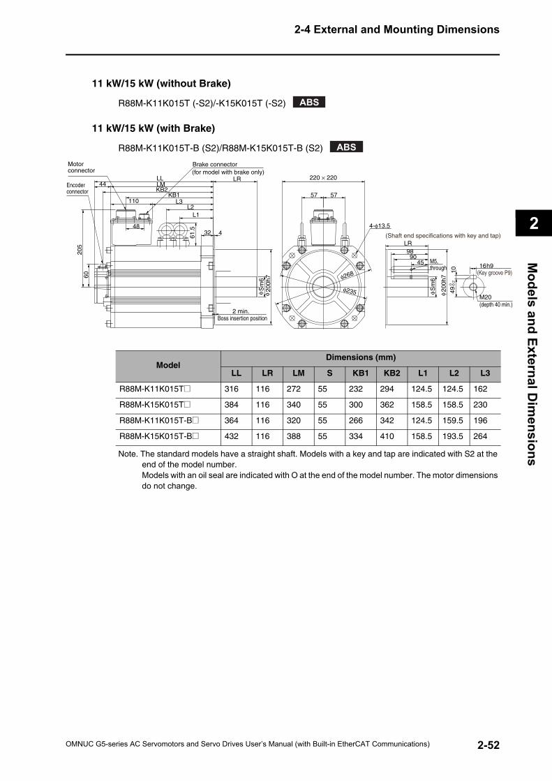
2-4 External and Mounting Dimensions
2
Models and External D
imensions
9)
.)
11 kW/15 kW (without Brake)
R88M-K11K015T (-S2)/-K15K015T (-S2)
11 kW/15 kW (with Brake)
R88M-K11K015T-B (S2)/R88M-K15K015T-B (S2)
Note. The standard models have a straight shaft. Models with a key and tap are indicated with S2 at the end of the model number.Models with an oil seal are indicated with O at the end of the model number. The motor dimensions do not change.
ABS
ABS
(Key groove P
M5, through
φ 200
h7
4590
98
49 0 -0
.210
16h9
LR
φ Sm
6
Encoder connector
Brake connectorMotor connector
4-φ13.532
205
60
61.548
LR 220 × 220
φ Sm
6
KB1KB2
L3110
φ 200
h7
LL44
L2
LM
57 57
L1
4
φ235
φ268
(Shaft end specifications with key and tap)
M20 (depth 40 min
(for model with brake only)
2 min.Boss insertion position
ModelDimensions (mm)
LL LR LM S KB1 KB2 L1 L2 L3
R88M-K11K015T@ 316 116 272 55 232 294 124.5 124.5 162
R88M-K15K015T@ 384 116 340 55 300 362 158.5 158.5 230
R88M-K11K015T-B@ 364 116 320 55 266 342 124.5 159.5 196
R88M-K15K015T-B@ 432 116 388 55 334 410 158.5 193.5 264
2-52OMNUC G5-series AC Servomotors and Servo Drives User’s Manual (with Built-in EtherCAT Communications)
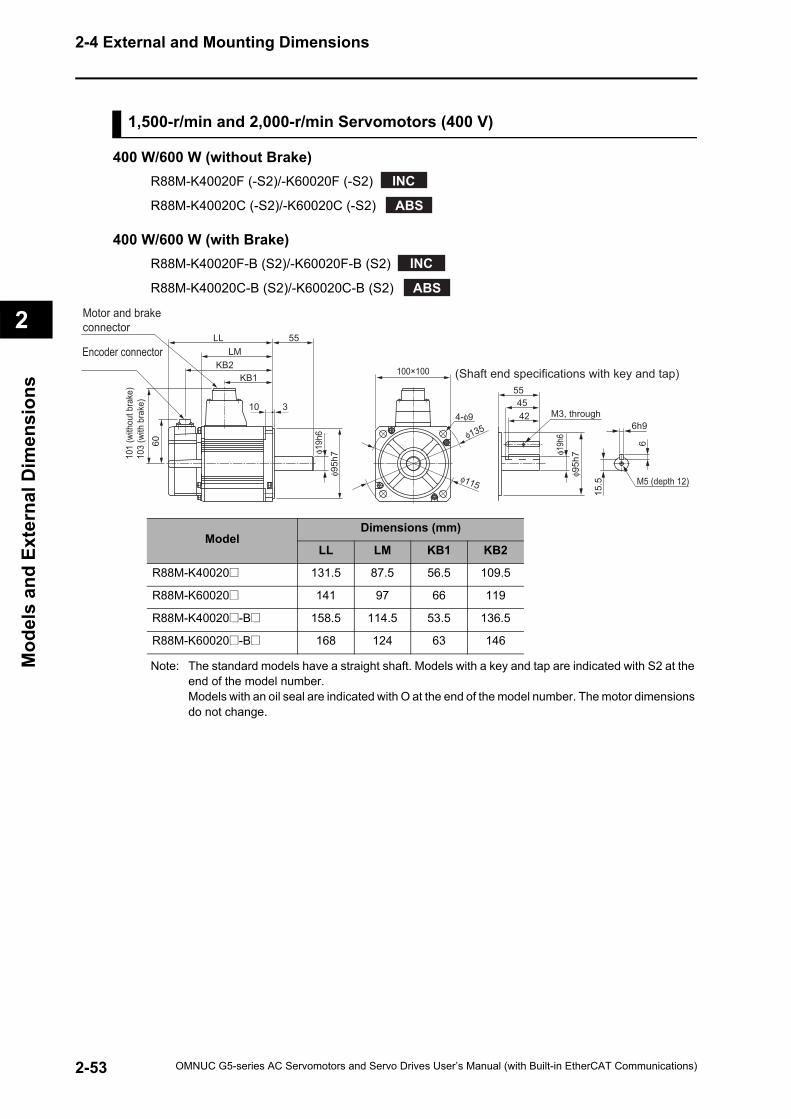
2-4 External and Mounting Dimensions
2
Mod
els
and
Exte
rnal
Dim
ensi
ons
1,500-r/min and 2,000-r/min Servomotors (400 V)
400 W/600 W (without Brake)R88M-K40020F (-S2)/-K60020F (-S2)
R88M-K40020C (-S2)/-K60020C (-S2)
400 W/600 W (with Brake)R88M-K40020F-B (S2)/-K60020F-B (S2)
R88M-K40020C-B (S2)/-K60020C-B (S2)
Note: The standard models have a straight shaft. Models with a key and tap are indicated with S2 at the end of the model number.Models with an oil seal are indicated with O at the end of the model number. The motor dimensions do not change.
ModelDimensions (mm)
LL LM KB1 KB2
R88M-K40020@ 131.5 87.5 56.5 109.5
R88M-K60020@ 141 97 66 119
R88M-K40020@-B@ 158.5 114.5 53.5 136.5
R88M-K60020@-B@ 168 124 63 146
INC
ABS
INC
ABS
100×100
4-φ9
Encoder connector
Motor and brakeconnector
101
(with
out b
rake
) 10
3 (w
ith b
rake
)60
LMKB2
KB1
55LL
310
φ95h
7
φ115
φ135
554542 M3, through
φ95h
7φ19h
6
φ19h
6
M5 (depth 12)
6h9
6
15.5
(Shaft end specifications with key and tap)
2-53 OMNUC G5-series AC Servomotors and Servo Drives User’s Manual (with Built-in EtherCAT Communications)
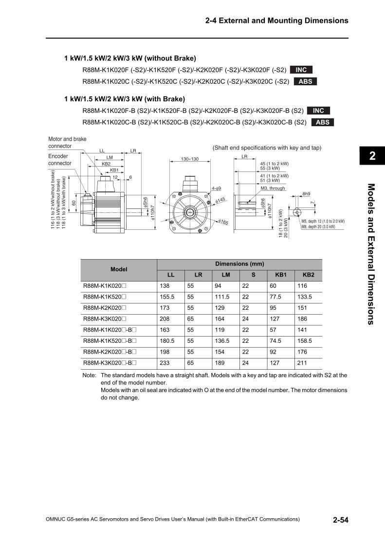
2-4 External and Mounting Dimensions
2
Models and External D
imensions
1 kW/1.5 kW/2 kW/3 kW (without Brake)R88M-K1K020F (-S2)/-K1K520F (-S2)/-K2K020F (-S2)/-K3K020F (-S2)
R88M-K1K020C (-S2)/-K1K520C (-S2)/-K2K020C (-S2)/-K3K020C (-S2)
1 kW/1.5 kW/2 kW/3 kW (with Brake)R88M-K1K020F-B (S2)/-K1K520F-B (S2)/-K2K020F-B (S2)/-K3K020F-B (S2)
R88M-K1K020C-B (S2)/-K1K520C-B (S2)/-K2K020C-B (S2)/-K3K020C-B (S2)
Note: The standard models have a straight shaft. Models with a key and tap are indicated with S2 at the end of the model number.Models with an oil seal are indicated with O at the end of the model number. The motor dimensions do not change.
INC
ABS
INC
ABS
Encoderconnector
Motor and brakeconnector
LMKB2
KB1
LRLL
116
(1 to
2 k
W/w
ithou
t bra
ke)
118
(3 k
W/w
ithou
t bra
ke)
118
(1 to
3 k
W/w
ith b
rake
)
60
130×13045 (1 to 2 kW)55 (3 kW)
41 (1 to 2 kW)51 (3 kW)
LR
M3, through
M5, depth 12 (1.0 to 2.0 kW) M8, depth 20 (3.0 kW)
8h9
7
18 (
1 to
2 k
W)
20 (
3 kW
)
(Shaft end specifications with key and tap)
612
φSh6
φ110
h7
4-φ9
φ165
φ145
φSh6
φ110
h7Model
Dimensions (mm)
LL LR LM S KB1 KB2
R88M-K1K020@ 138 55 94 22 60 116
R88M-K1K520@ 155.5 55 111.5 22 77.5 133.5
R88M-K2K020@ 173 55 129 22 95 151
R88M-K3K020@ 208 65 164 24 127 186
R88M-K1K020@-B@ 163 55 119 22 57 141
R88M-K1K520@-B@ 180.5 55 136.5 22 74.5 158.5
R88M-K2K020@-B@ 198 55 154 22 92 176
R88M-K3K020@-B@ 233 65 189 24 127 211
2-54OMNUC G5-series AC Servomotors and Servo Drives User’s Manual (with Built-in EtherCAT Communications)

2-4 External and Mounting Dimensions
2
Mod
els
and
Exte
rnal
Dim
ensi
ons
4 kW/5 kW (without Brake)R88M-K4K020F (-S2)/-K5K020F (-S2) R88M-K4K020C (-S2)/-K5K020C (-S2)
4 kW/5 kW (with Brake)R88M-K4K020F-B (S2)/-K5K020F-B (S2) R88M-K4K020C-B (S2)/-K5K020C-B (S2)
Note. The standard models have a straight shaft. Models with a key and tap are indicated with S2 at the end of the model number.Models with an oil seal are indicated with O at the end of the model number. The motor dimensions do not change.
ModelDimensions (mm)
LL LM KB1 KB2
R88M-K4K020@ 177 133 96 155
R88M-K5K020@ 196 152 115 174
R88M-K4K020@-B@ 202 158 96 180
R88M-K5K020@-B@ 221 177 115 199
INCABS
INCABS
Encoderconnector
Motor and brakeconnector
LMKB2
KB1
70LL
140
60
176×176
705550
M3, through
(Shaft end specifications with key and tap)
3.218
φ35h
6
φ114
.3h7
4-φ13.5
φ200
φ233
φ35h
6
φ114
.3h7
M12 (depth 25)
10h9
8
30
2-55 OMNUC G5-series AC Servomotors and Servo Drives User’s Manual (with Built-in EtherCAT Communications)
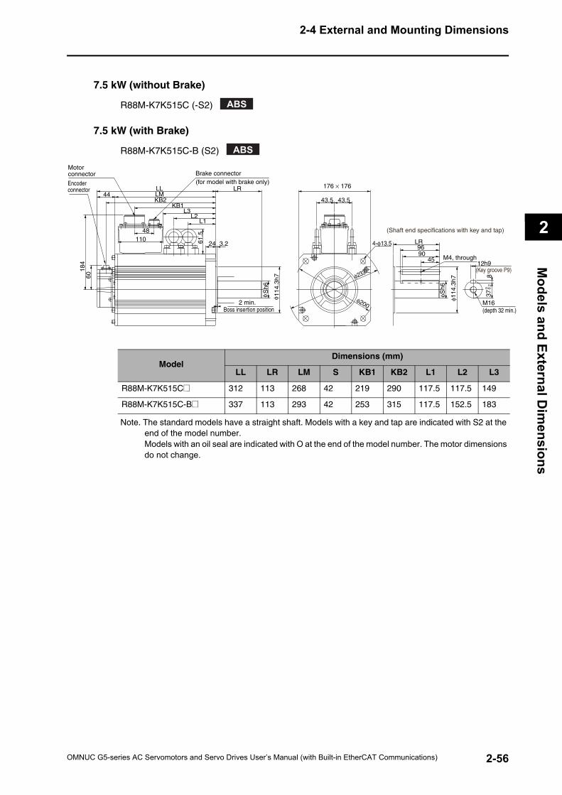
2-4 External and Mounting Dimensions
2
Models and External D
imensions
7.5 kW (without Brake)
R88M-K7K515C (-S2)
7.5 kW (with Brake)
R88M-K7K515C-B (S2)
Note. The standard models have a straight shaft. Models with a key and tap are indicated with S2 at the end of the model number.Models with an oil seal are indicated with O at the end of the model number. The motor dimensions do not change.
ABS
ABS
4-φ13.5
43.543.5
φ233
φ200
(Key groove P9)
φ114
.3h7
φSh6
45
37 0 -0
.2
90
12h9
8
LR96
L1
44LL
184
61.5
L2L3
48110
KB1
60
KB2LM
24
LR
φ Sh6
φ 114
.3h7
3.2
M4, through
Encoder connector
Brake connectorMotor connector
176 × 176
(Shaft end specifications with key and tap)
M16 (depth 32 min.)
(for model with brake only)
2 min.Boss insertion position
ModelDimensions (mm)
LL LR LM S KB1 KB2 L1 L2 L3
R88M-K7K515C@ 312 113 268 42 219 290 117.5 117.5 149
R88M-K7K515C-B@ 337 113 293 42 253 315 117.5 152.5 183
2-56OMNUC G5-series AC Servomotors and Servo Drives User’s Manual (with Built-in EtherCAT Communications)
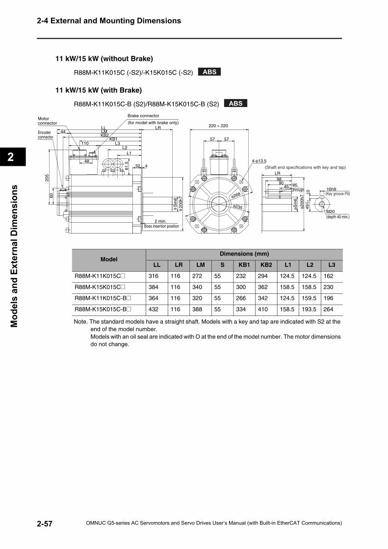
2-4 External and Mounting Dimensions
2
Mod
els
and
Exte
rnal
Dim
ensi
ons
)
)
11 kW/15 kW (without Brake)
R88M-K11K015C (-S2)/-K15K015C (-S2)
11 kW/15 kW (with Brake)
R88M-K11K015C-B (S2)/R88M-K15K015C-B (S2)
Note. The standard models have a straight shaft. Models with a key and tap are indicated with S2 at the end of the model number.Models with an oil seal are indicated with O at the end of the model number. The motor dimensions do not change.
ABS
ABS
(Key groove P9
LR
16h9
1049
0 -0.2
9890
45
φ200
h7
φSm
6
4-φ13.5
L1
5757
LM
L2
44LL
φ20
0h7
110 L3
KB2KB1
φS
m6
LR
48
61.5
6020
5
32 4
φ268
φ235
M5, through
Encoder connector
Brake connectorMotor connector
220 × 220
(Shaft end specifications with key and tap)
M20(depth 40 min.
(for model with brake only)
2 min.Boss insertion position
ModelDimensions (mm)
LL LR LM S KB1 KB2 L1 L2 L3
R88M-K11K015C@ 316 116 272 55 232 294 124.5 124.5 162
R88M-K15K015C@ 384 116 340 55 300 362 158.5 158.5 230
R88M-K11K015C-B@ 364 116 320 55 266 342 124.5 159.5 196
R88M-K15K015C-B@ 432 116 388 55 334 410 158.5 193.5 264
2-57 OMNUC G5-series AC Servomotors and Servo Drives User’s Manual (with Built-in EtherCAT Communications)
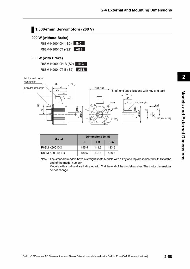
2-4 External and Mounting Dimensions
2
Models and External D
imensions
1,000-r/min Servomotors (200 V)
900 W (without Brake)R88M-K90010H (-S2)
R88M-K90010T (-S2)
900 W (with Brake)R88M-K90010H-B (S2)
R88M-K90010T-B (S2)
Note: The standard models have a straight shaft. Models with a key and tap are indicated with S2 at the end of the model number.Models with an oil seal are indicated with O at the end of the model number. The motor dimensions do not change.
INC
ABS
INC
ABS
Encoder connector
Motor and brakeconnector
LMKB2
77.5
70LL
116
60
130×130
45
41
70
M3, through8h9
718
(Shaft end specifications with key and tap)
612
φ22h
6
φ 110
h7
4-φ9
φ165
φ145
φ22h
6
φ 110
h7
M5 (depth 12)
ModelDimensions (mm)
LL LM KB2
R88M-K90010@ 155.5 111.5 133.5
R88M-K90010@-B@ 180.5 136.5 158.5
2-58OMNUC G5-series AC Servomotors and Servo Drives User’s Manual (with Built-in EtherCAT Communications)
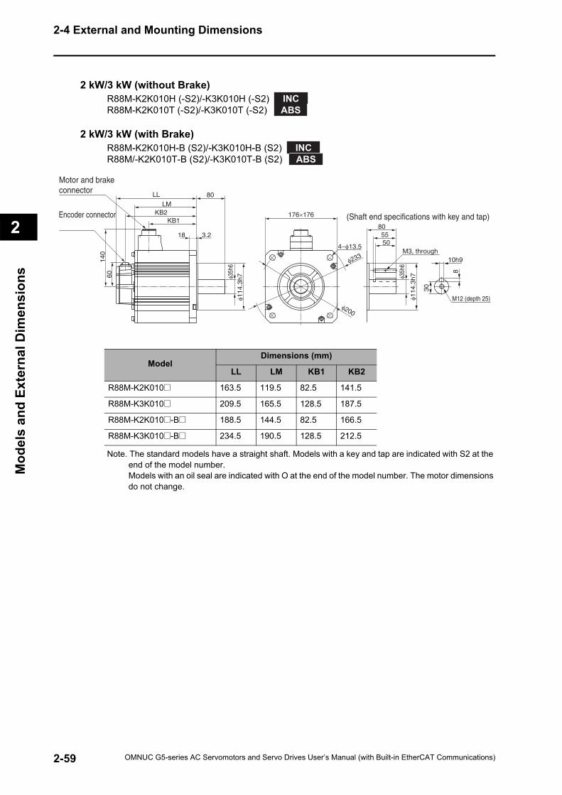
2-4 External and Mounting Dimensions
2
Mod
els
and
Exte
rnal
Dim
ensi
ons
2 kW/3 kW (without Brake)R88M-K2K010H (-S2)/-K3K010H (-S2) R88M-K2K010T (-S2)/-K3K010T (-S2)
2 kW/3 kW (with Brake)R88M-K2K010H-B (S2)/-K3K010H-B (S2) R88M/-K2K010T-B (S2)/-K3K010T-B (S2)
Note. The standard models have a straight shaft. Models with a key and tap are indicated with S2 at the end of the model number.Models with an oil seal are indicated with O at the end of the model number. The motor dimensions do not change.
INCABS
INCABS
Encoder connector
Motor and brakeconnector
LMKB2
KB1
80LL
140
60
176×176
805550
M3, through
(Shaft end specifications with key and tap)
3.218φ3
5h6
φ35h
6
φ114
.3h7
4−φ13.5
φ200
φ233
φ114
.3h7
M12 (depth 25)
10h9
8
30
ModelDimensions (mm)
LL LM KB1 KB2
R88M-K2K010@ 163.5 119.5 82.5 141.5
R88M-K3K010@ 209.5 165.5 128.5 187.5
R88M-K2K010@-B@ 188.5 144.5 82.5 166.5
R88M-K3K010@-B@ 234.5 190.5 128.5 212.5
2-59 OMNUC G5-series AC Servomotors and Servo Drives User’s Manual (with Built-in EtherCAT Communications)
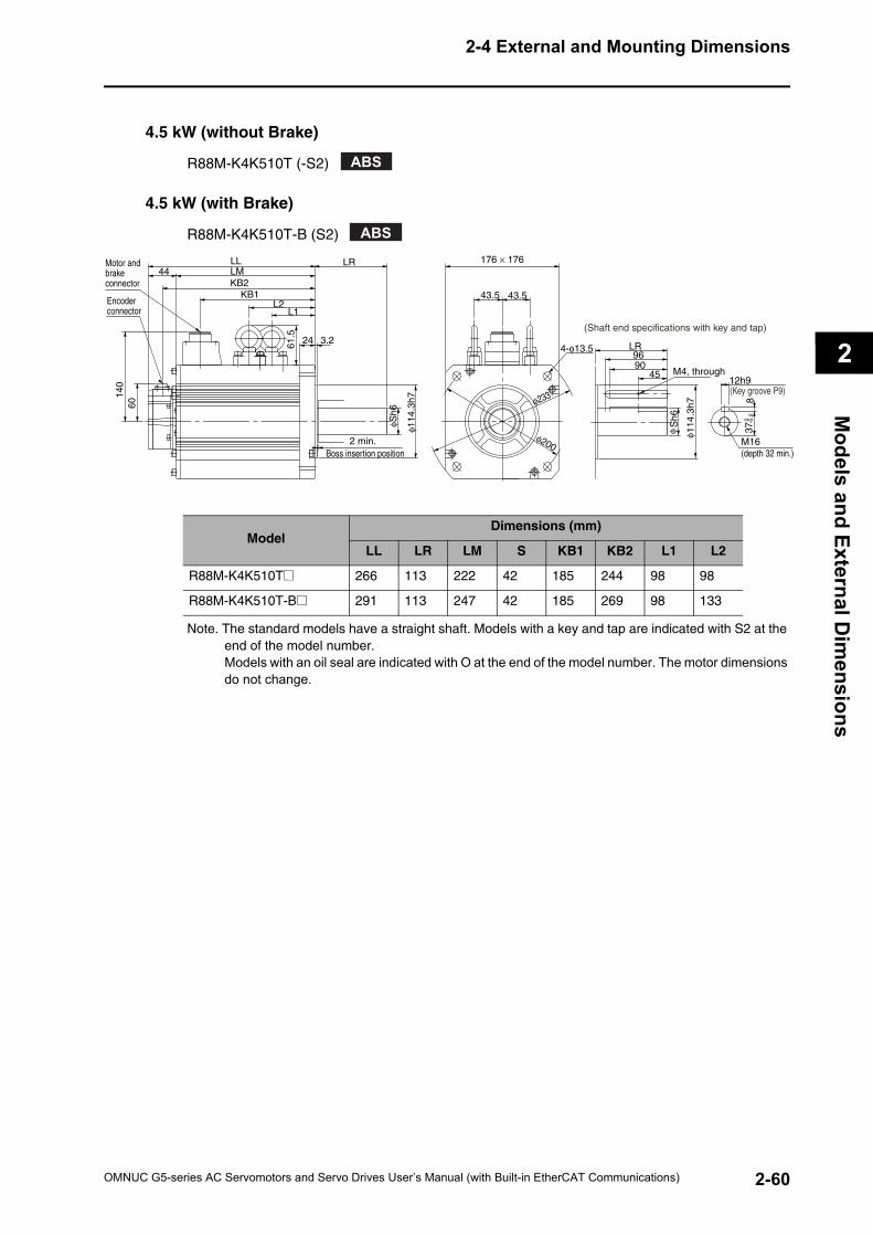
2-4 External and Mounting Dimensions
2
Models and External D
imensions
4.5 kW (without Brake)
R88M-K4K510T (-S2)
4.5 kW (with Brake)
R88M-K4K510T-B (S2)
Note. The standard models have a straight shaft. Models with a key and tap are indicated with S2 at the end of the model number.Models with an oil seal are indicated with O at the end of the model number. The motor dimensions do not change.
ABS
ABS
4-φ13.5
43.543.5
φ233
φ200
(Key groove P9)
φ 114
.3h7
φS
h6
45
37 0 -0
.2
90
12h9
8
LR96
Motor and brake connector
L1
61.5
L2
60
KB2LM
24
LR
φSh6
φ114
.3h7
3.2
KB1
140
LL44
M4, through
Encoder connector
176 × 176
(Shaft end specifications with key and tap)
M16(depth 32 min.)
2 min.Boss insertion position
ModelDimensions (mm)
LL LR LM S KB1 KB2 L1 L2
R88M-K4K510T@ 266 113 222 42 185 244 98 98
R88M-K4K510T-B@ 291 113 247 42 185 269 98 133
2-60OMNUC G5-series AC Servomotors and Servo Drives User’s Manual (with Built-in EtherCAT Communications)

2-4 External and Mounting Dimensions
2
Mod
els
and
Exte
rnal
Dim
ensi
ons
6 kW (without Brake)
R88M-K6K010T (-S2)
6 kW (with Brake)
R88M-K6K010T-B (S2)
Note. The standard models have a straight shaft. Models with a key and tap are indicated with S2 at the end of the model number.Models with an oil seal are indicated with O at the end of the model number. The motor dimensions do not change.
ABS
ABS
4-φ13.5
43.543.5
φ233
φ200
(Key groove P9)
φ 114
.3h7
φS
h6
45
37 0 -0
.2
90
12h9
8
LR96
L1
LL
184
61.5
L2L3
48110
KB1
60
KB2LM
24
LR
φ Sh6
φ 114
.3h7
3.2
44
M4, through
Encoder connector
Brake connectorMotor connector
176 × 176
(Shaft end specifications with key and tap)
M16(depth 32 min.)
(for model with brake only)
2 min.Boss insertion position
ModelDimensions (mm)
LL LR LM S KB1 KB2 L1 L2 L3
R88M-K6K010T@ 312 113 268 42 219 290 117.5 117.5 149
R88M-K6K010T-B@ 337 113 293 42 253 315 117.5 152.5 183
2-61 OMNUC G5-series AC Servomotors and Servo Drives User’s Manual (with Built-in EtherCAT Communications)
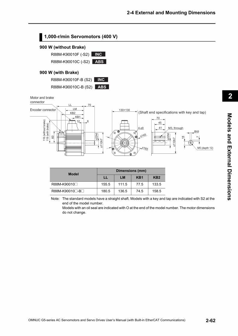
2-4 External and Mounting Dimensions
2
Models and External D
imensions
1,000-r/min Servomotors (400 V)
900 W (without Brake)R88M-K90010F (-S2)
R88M-K90010C (-S2)
900 W (with Brake)R88M-K90010F-B (S2)
R88M-K90010C-B (S2)
Note: The standard models have a straight shaft. Models with a key and tap are indicated with S2 at the end of the model number.Models with an oil seal are indicated with O at the end of the model number. The motor dimensions do not change.
INC
ABS
INC
ABS
Encoder connector
Motor and brakeconnector
LMKB2
KB1
70LL
60
130×130
45
41
70
M3, through
M5 (depth 12)
8h9
718
(Shaft end specifications with key and tap)
612
φ22h
6
φ110
h7
4-φ9
φ165
φ145
φ22h
6
φ 110
h7116
(with
out b
rake
) 11
8 (w
ith b
rake
)
ModelDimensions (mm)
LL LM KB1 KB2
R88M-K90010@ 155.5 111.5 77.5 133.5
R88M-K90010@-B@ 180.5 136.5 74.5 158.5
2-62OMNUC G5-series AC Servomotors and Servo Drives User’s Manual (with Built-in EtherCAT Communications)
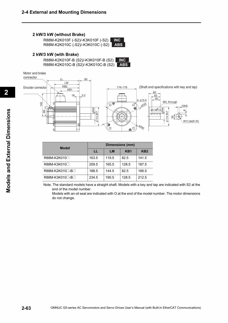
2-4 External and Mounting Dimensions
2
Mod
els
and
Exte
rnal
Dim
ensi
ons
2 kW/3 kW (without Brake)R88M-K2K010F (-S2)/-K3K010F (-S2) R88M-K2K010C (-S2)/-K3K010C (-S2)
2 kW/3 kW (with Brake)R88M-K2K010F-B (S2)/-K3K010F-B (S2) R88M-K2K010C-B (S2)/-K3K010C-B (S2)
Note. The standard models have a straight shaft. Models with a key and tap are indicated with S2 at the end of the model number.Models with an oil seal are indicated with O at the end of the model number. The motor dimensions do not change.
INCABS
INCABS
Encoder connector
Motor and brakeconnector
LMKB2
KB1
80LL
140
60
176×176
805550
M3, through
(Shaft end specifications with key and tap)
3.218φ3
5h6
φ35h
6
φ114
.3h7
4−φ13.5
φ200
φ233
φ114
.3h7
M12 (depth 25)
10h9
8
30
ModelDimensions (mm)
LL LM KB1 KB2
R88M-K2K010@ 163.5 119.5 82.5 141.5
R88M-K3K010@ 209.5 165.5 128.5 187.5
R88M-K2K010@-B@ 188.5 144.5 82.5 166.5
R88M-K3K010@-B@ 234.5 190.5 128.5 212.5
2-63 OMNUC G5-series AC Servomotors and Servo Drives User’s Manual (with Built-in EtherCAT Communications)
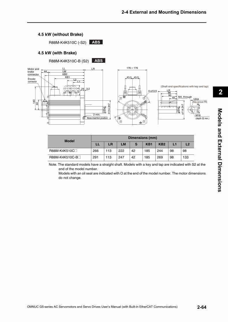
2-4 External and Mounting Dimensions
2
Models and External D
imensions
4.5 kW (without Brake)
R88M-K4K510C (-S2)
4.5 kW (with Brake)
R88M-K4K510C-B (S2)
Note. The standard models have a straight shaft. Models with a key and tap are indicated with S2 at the end of the model number.Models with an oil seal are indicated with O at the end of the model number. The motor dimensions do not change.
ABS
ABS
4-φ13.5
43.5 43.5
φ200
φ233 (Key groove P9)
8
12h9
90
37 0 -0
.2
45
φSh6
φ114
.3h7
96LR
44LL
140
KB1
3.2
φ 114
.3h7
φ Sh6
LR
24
LMKB2
60
L261
.5
L1
M4, through
Encoder connector
Motor and brake connector
176 × 176
(Shaft end specifications with key and tap)
M16(depth 32 min.)
2 min.Boss insertion position
ModelDimensions (mm)
LL LR LM S KB1 KB2 L1 L2
R88M-K4K510C@ 266 113 222 42 185 244 98 98
R88M-K4K510C-B@ 291 113 247 42 185 269 98 133
2-64OMNUC G5-series AC Servomotors and Servo Drives User’s Manual (with Built-in EtherCAT Communications)
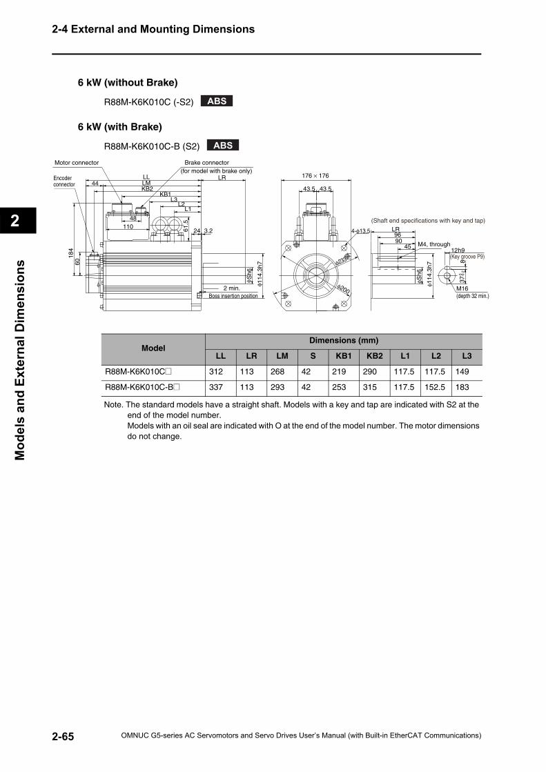
2-4 External and Mounting Dimensions
2
Mod
els
and
Exte
rnal
Dim
ensi
ons
6 kW (without Brake)
R88M-K6K010C (-S2)
6 kW (with Brake)
R88M-K6K010C-B (S2)
Note. The standard models have a straight shaft. Models with a key and tap are indicated with S2 at the end of the model number.Models with an oil seal are indicated with O at the end of the model number. The motor dimensions do not change.
ABS
ABS
4-φ13.5
43.5 43.5
φ200
φ233 (Key groove P9)
8
12h9
90
37 0 -0
.2
45
φSh6
φ114
.3h7
96LR3.2
φ 114
.3h7
φ Sh6
LR
24
LMKB2
60
KB1
11048
L3L2
61.5
184
LL44
L1
M4, through
Encoder connector
176 × 176
(Shaft end specifications with key and tap)
Motor connector Brake connector
M16(depth 32 min.)
(for model with brake only)
2 min.Boss insertion position
ModelDimensions (mm)
LL LR LM S KB1 KB2 L1 L2 L3
R88M-K6K010C@ 312 113 268 42 219 290 117.5 117.5 149
R88M-K6K010C-B@ 337 113 293 42 253 315 117.5 152.5 183
2-65 OMNUC G5-series AC Servomotors and Servo Drives User’s Manual (with Built-in EtherCAT Communications)
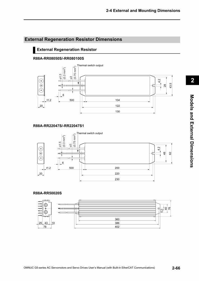
2-4 External and Mounting Dimensions
2
Models and External D
imensions
External Regeneration Resistor Dimensions
External Regeneration Resistor
R88A-RR08050S/-RR080100S
R88A-RR22047S/-RR22047S1
R88A-RR50020S
20
t1.2 104
122
130
43.5
28
4.2
6
Thermal switch output
500
ϕ3 (0.7
5 m
m2 )
ϕ1.5
(0.3
mm
2 )
20
t1.2 200
220
230
6248
4.2
6
Thermal switch output
500
ϕ3 (0.7
5 m
m2 )
ϕ1.5
(0.3
mm
2 )
360386402
4325 1078
76405.
2
2-66OMNUC G5-series AC Servomotors and Servo Drives User’s Manual (with Built-in EtherCAT Communications)
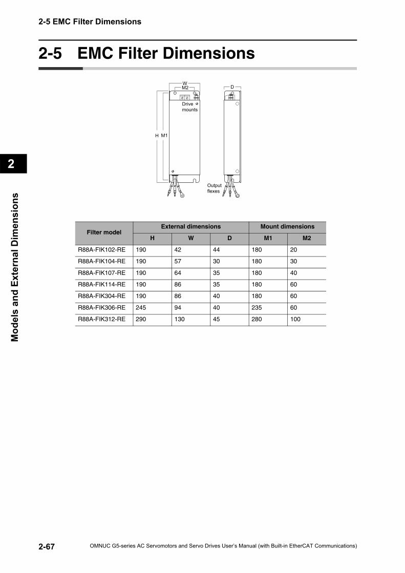
2-5 EMC Filter Dimensions
2
Mod
els
and
Exte
rnal
Dim
ensi
ons
2-5 EMC Filter Dimensions
H
WD
Drivemounts
M1
M2
Outputflexes
Filter modelExternal dimensions Mount dimensions
H W D M1 M2
R88A-FIK102-RE 190 42 44 180 20
R88A-FIK104-RE 190 57 30 180 30
R88A-FIK107-RE 190 64 35 180 40
R88A-FIK114-RE 190 86 35 180 60
R88A-FIK304-RE 190 86 40 180 60
R88A-FIK306-RE 245 94 40 235 60
R88A-FIK312-RE 290 130 45 280 100
2-67 OMNUC G5-series AC Servomotors and Servo Drives User’s Manual (with Built-in EtherCAT Communications)
3
SpecificationsThis chapter provides the general specifications, characteristics, connectorspecifications, and I/O circuits of the Servo Drives as well as the generalspecifications, characteristics, encoder specifications of the Servomotors andother peripheral devices.
3-1 Servo Drive Specifications ..........................................3-13-2 Overload Characteristics
(Electronic Thermal Function)...................................3-363-3 Servomotor Specifications ........................................3-373-4 Cable and Connector Specifications ........................3-633-5 External Regeneration Resistor Specifications.......3-863-6 EMC Filter Specifications...........................................3-88
OMNUC G5-series AC Servomotors and Servo Drives User’s Manual (with Built-in EtherCAT Communications)
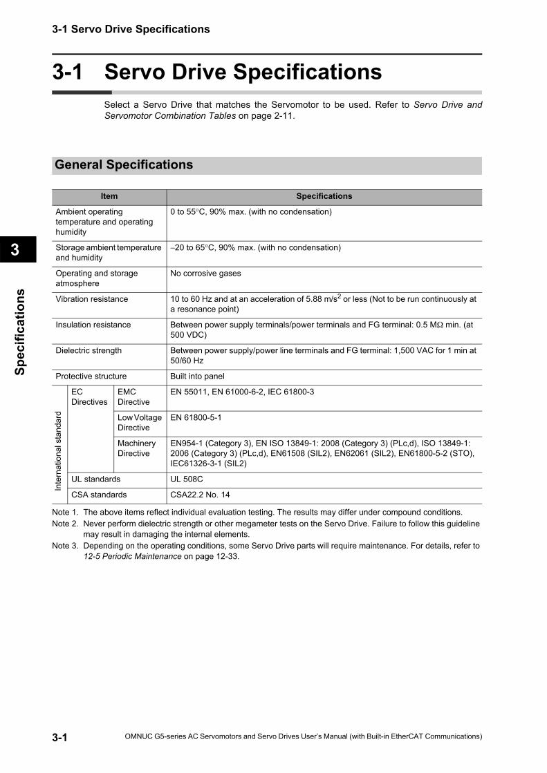
3-1 Servo Drive Specifications
3
Spec
ifica
tions
3-1 Servo Drive SpecificationsSelect a Servo Drive that matches the Servomotor to be used. Refer to Servo Drive andServomotor Combination Tables on page 2-11.
General Specifications
Note 1. The above items reflect individual evaluation testing. The results may differ under compound conditions.Note 2. Never perform dielectric strength or other megameter tests on the Servo Drive. Failure to follow this guideline
may result in damaging the internal elements.Note 3. Depending on the operating conditions, some Servo Drive parts will require maintenance. For details, refer to
12-5 Periodic Maintenance on page 12-33.
Item Specifications
Ambient operating temperature and operating humidity
0 to 55°C, 90% max. (with no condensation)
Storage ambient temperature and humidity
−20 to 65°C, 90% max. (with no condensation)
Operating and storage atmosphere
No corrosive gases
Vibration resistance 10 to 60 Hz and at an acceleration of 5.88 m/s2 or less (Not to be run continuously at a resonance point)
Insulation resistance Between power supply terminals/power terminals and FG terminal: 0.5 MΩ min. (at 500 VDC)
Dielectric strength Between power supply/power line terminals and FG terminal: 1,500 VAC for 1 min at 50/60 Hz
Protective structure Built into panel
EC Directives
EMC Directive
EN 55011, EN 61000-6-2, IEC 61800-3
Low Voltage Directive
EN 61800-5-1
Machinery Directive
EN954-1 (Category 3), EN ISO 13849-1: 2008 (Category 3) (PLc,d), ISO 13849-1: 2006 (Category 3) (PLc,d), EN61508 (SIL2), EN62061 (SIL2), EN61800-5-2 (STO), IEC61326-3-1 (SIL2)
UL standards UL 508C
CSA standards CSA22.2 No. 14
Inte
rnat
iona
l sta
ndar
d
3-1 OMNUC G5-series AC Servomotors and Servo Drives User’s Manual (with Built-in EtherCAT Communications)
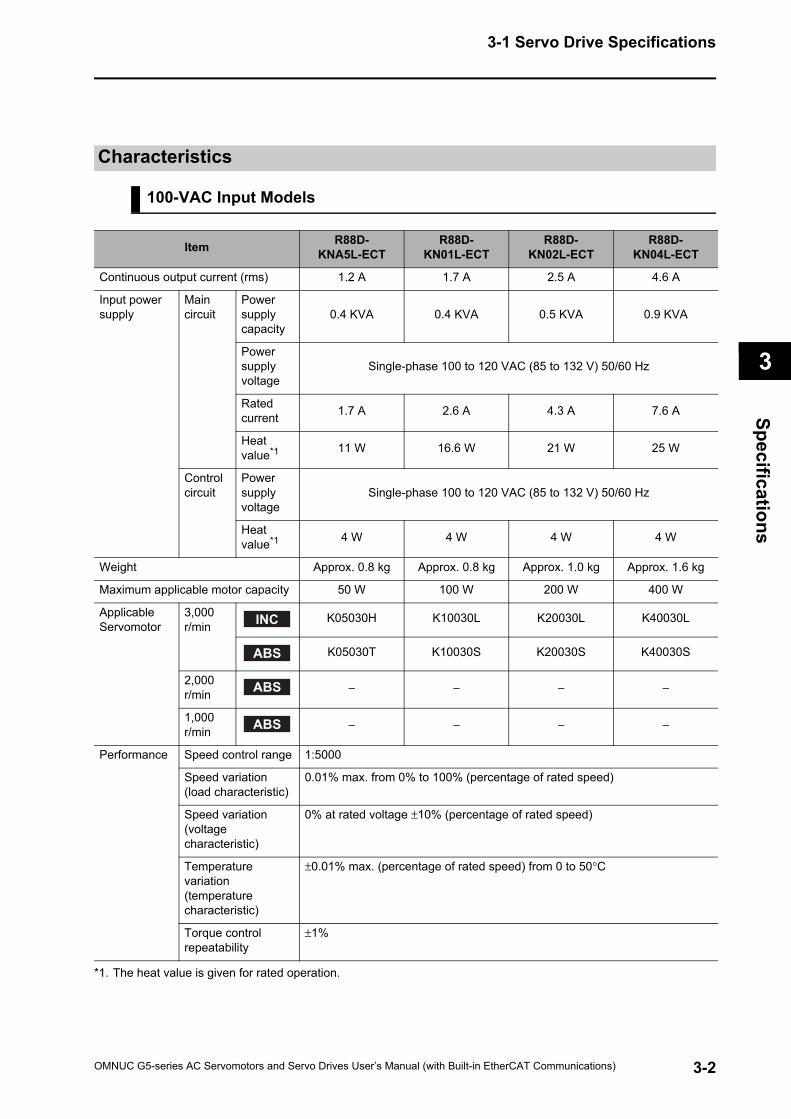
3-1 Servo Drive Specifications
3
Specifications
Characteristics
100-VAC Input Models
*1. The heat value is given for rated operation.
Item R88D-KNA5L-ECT
R88D-KN01L-ECT
R88D-KN02L-ECT
R88D-KN04L-ECT
Continuous output current (rms) 1.2 A 1.7 A 2.5 A 4.6 A
Input power supply
Main circuit
Power supply capacity
0.4 KVA 0.4 KVA 0.5 KVA 0.9 KVA
Power supply voltage
Single-phase 100 to 120 VAC (85 to 132 V) 50/60 Hz
Rated current 1.7 A 2.6 A 4.3 A 7.6 A
Heat value*1 11 W 16.6 W 21 W 25 W
Control circuit
Power supply voltage
Single-phase 100 to 120 VAC (85 to 132 V) 50/60 Hz
Heat value*1 4 W 4 W 4 W 4 W
Weight Approx. 0.8 kg Approx. 0.8 kg Approx. 1.0 kg Approx. 1.6 kg
Maximum applicable motor capacity 50 W 100 W 200 W 400 W
Applicable Servomotor
3,000 r/min
K05030H K10030L K20030L K40030L
K05030T K10030S K20030S K40030S
2,000 r/min − − − −
1,000 r/min − − − −
Performance Speed control range 1:5000
Speed variation (load characteristic)
0.01% max. from 0% to 100% (percentage of rated speed)
Speed variation (voltage characteristic)
0% at rated voltage ±10% (percentage of rated speed)
Temperature variation (temperature characteristic)
±0.01% max. (percentage of rated speed) from 0 to 50°C
Torque control repeatability
±1%
INC
ABS
ABS
ABS
3-2OMNUC G5-series AC Servomotors and Servo Drives User’s Manual (with Built-in EtherCAT Communications)
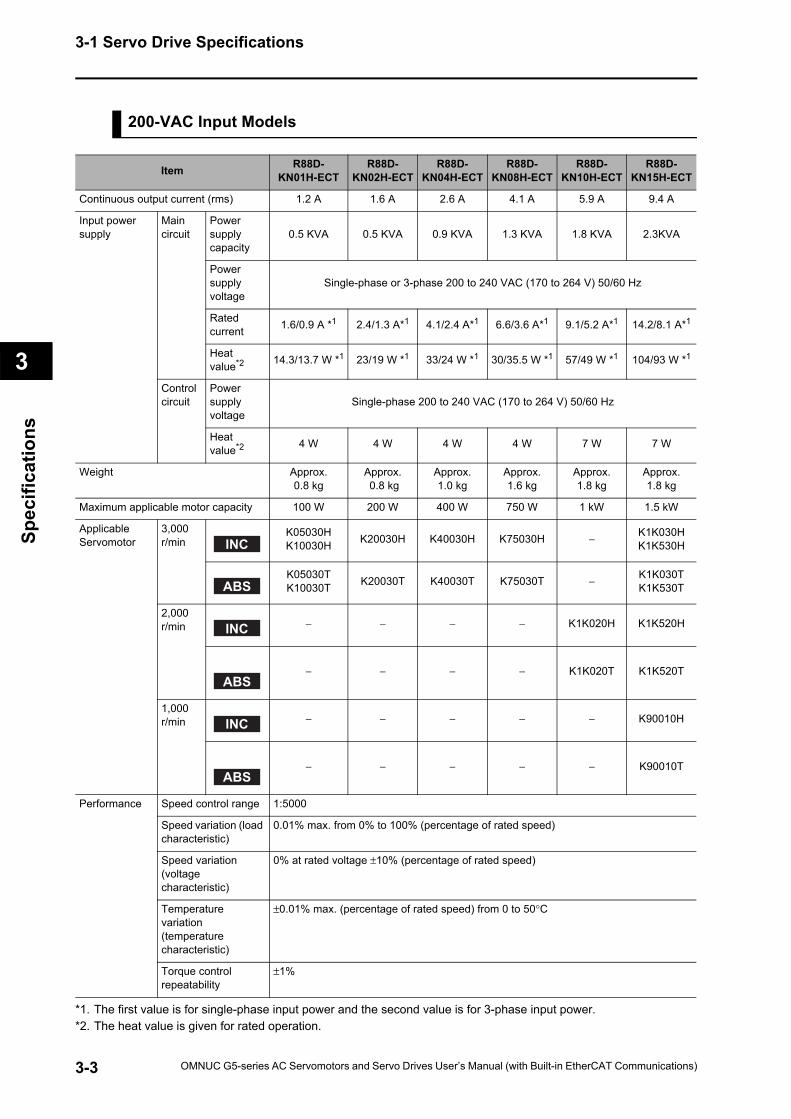
3-1 Servo Drive Specifications
3
Spec
ifica
tions
200-VAC Input Models
*1. The first value is for single-phase input power and the second value is for 3-phase input power. *2. The heat value is given for rated operation.
Item R88D-KN01H-ECT
R88D-KN02H-ECT
R88D-KN04H-ECT
R88D-KN08H-ECT
R88D-KN10H-ECT
R88D-KN15H-ECT
Continuous output current (rms) 1.2 A 1.6 A 2.6 A 4.1 A 5.9 A 9.4 A
Input power supply
Main circuit
Power supply capacity
0.5 KVA 0.5 KVA 0.9 KVA 1.3 KVA 1.8 KVA 2.3KVA
Power supply voltage
Single-phase or 3-phase 200 to 240 VAC (170 to 264 V) 50/60 Hz
Rated current 1.6/0.9 A *1 2.4/1.3 A*1 4.1/2.4 A*1 6.6/3.6 A*1 9.1/5.2 A*1 14.2/8.1 A*1
Heat value*2 14.3/13.7 W *1 23/19 W *1 33/24 W *1 30/35.5 W *1 57/49 W *1 104/93 W *1
Control circuit
Power supply voltage
Single-phase 200 to 240 VAC (170 to 264 V) 50/60 Hz
Heat value*2 4 W 4 W 4 W 4 W 7 W 7 W
Weight Approx. 0.8 kg
Approx. 0.8 kg
Approx. 1.0 kg
Approx. 1.6 kg
Approx. 1.8 kg
Approx. 1.8 kg
Maximum applicable motor capacity 100 W 200 W 400 W 750 W 1 kW 1.5 kW
Applicable Servomotor
3,000 r/min
K05030HK10030H K20030H K40030H K75030H − K1K030H
K1K530H
K05030TK10030T K20030T K40030T K75030T − K1K030T
K1K530T
2,000 r/min − − − − K1K020H K1K520H
− − − − K1K020T K1K520T
1,000 r/min − − − − − K90010H
− − − − − K90010T
Performance Speed control range 1:5000
Speed variation (load characteristic)
0.01% max. from 0% to 100% (percentage of rated speed)
Speed variation (voltage characteristic)
0% at rated voltage ±10% (percentage of rated speed)
Temperature variation (temperature characteristic)
±0.01% max. (percentage of rated speed) from 0 to 50°C
Torque control repeatability
±1%
INC
ABS
INC
ABS
INC
ABS
3-3 OMNUC G5-series AC Servomotors and Servo Drives User’s Manual (with Built-in EtherCAT Communications)
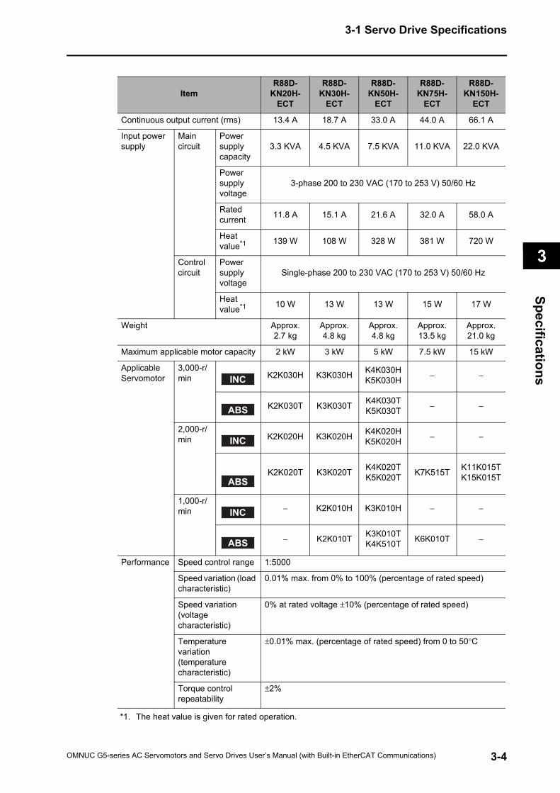
3-1 Servo Drive Specifications
3
Specifications
*1. The heat value is given for rated operation.
ItemR88D-
KN20H-ECT
R88D-KN30H-
ECT
R88D-KN50H-
ECT
R88D-KN75H-
ECT
R88D-KN150H-
ECT
Continuous output current (rms) 13.4 A 18.7 A 33.0 A 44.0 A 66.1 A
Input power supply
Main circuit
Power supply capacity
3.3 KVA 4.5 KVA 7.5 KVA 11.0 KVA 22.0 KVA
Power supply voltage
3-phase 200 to 230 VAC (170 to 253 V) 50/60 Hz
Rated current 11.8 A 15.1 A 21.6 A 32.0 A 58.0 A
Heat value*1 139 W 108 W 328 W 381 W 720 W
Control circuit
Power supply voltage
Single-phase 200 to 230 VAC (170 to 253 V) 50/60 Hz
Heat value*1 10 W 13 W 13 W 15 W 17 W
Weight Approx. 2.7 kg
Approx. 4.8 kg
Approx. 4.8 kg
Approx. 13.5 kg
Approx. 21.0 kg
Maximum applicable motor capacity 2 kW 3 kW 5 kW 7.5 kW 15 kW
Applicable Servomotor
3,000-r/min K2K030H K3K030H K4K030H
K5K030H − −
K2K030T K3K030T K4K030TK5K030T − −
2,000-r/min K2K020H K3K020H K4K020H
K5K020H − −
K2K020T K3K020T K4K020TK5K020T K7K515T K11K015T
K15K015T
1,000-r/min − K2K010H K3K010H − −
− K2K010T K3K010TK4K510T K6K010T −
Performance Speed control range 1:5000
Speed variation (load characteristic)
0.01% max. from 0% to 100% (percentage of rated speed)
Speed variation (voltage characteristic)
0% at rated voltage ±10% (percentage of rated speed)
Temperature variation (temperature characteristic)
±0.01% max. (percentage of rated speed) from 0 to 50°C
Torque control repeatability
±2%
INC
ABS
INC
ABS
INC
ABS
3-4OMNUC G5-series AC Servomotors and Servo Drives User’s Manual (with Built-in EtherCAT Communications)
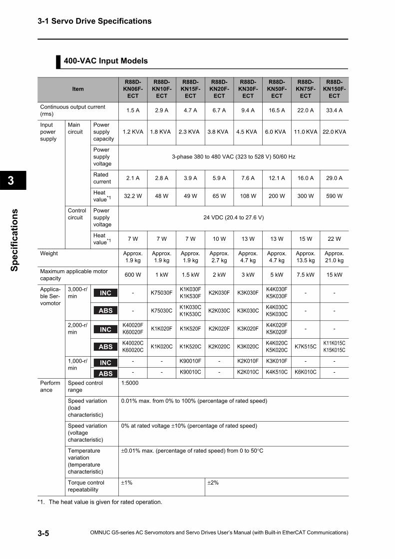
3-1 Servo Drive Specifications
3
Spec
ifica
tions
400-VAC Input Models
*1. The heat value is given for rated operation.
ItemR88D-
KN06F-ECT
R88D-KN10F-
ECT
R88D-KN15F-
ECT
R88D-KN20F-
ECT
R88D-KN30F-
ECT
R88D-KN50F-
ECT
R88D-KN75F-
ECT
R88D-KN150F-
ECT
Continuous output current (rms) 1.5 A 2.9 A 4.7 A 6.7 A 9.4 A 16.5 A 22.0 A 33.4 A
Input power supply
Main circuit
Power supply capacity
1.2 KVA 1.8 KVA 2.3 KVA 3.8 KVA 4.5 KVA 6.0 KVA 11.0 KVA 22.0 KVA
Power supply voltage
3-phase 380 to 480 VAC (323 to 528 V) 50/60 Hz
Rated current 2.1 A 2.8 A 3.9 A 5.9 A 7.6 A 12.1 A 16.0 A 29.0 A
Heat value*1 32.2 W 48 W 49 W 65 W 108 W 200 W 300 W 590 W
Control circuit
Power supply voltage
24 VDC (20.4 to 27.6 V)
Heat value*1 7 W 7 W 7 W 10 W 13 W 13 W 15 W 22 W
Weight Approx. 1.9 kg
Approx. 1.9 kg
Approx. 1.9 kg
Approx. 2.7 kg
Approx. 4.7 kg
Approx. 4.7 kg
Approx. 13.5 kg
Approx. 21.0 kg
Maximum applicable motor capacity 600 W 1 kW 1.5 kW 2 kW 3 kW 5 kW 7.5 kW 15 kW
Applica-ble Ser-vomotor
3,000-r/min - K75030F K1K030F
K1K530F K2K030F K3K030F K4K030FK5K030F - -
- K75030C K1K030CK1K530C K2K030C K3K030C K4K030C
K5K030C - -
2,000-r/min
K40020FK60020F K1K020F K1K520F K2K020F K3K020F K4K020F
K5K020F - -
K40020CK60020C K1K020C K1K520C K2K020C K3K020C K4K020C
K5K020C K7K515C K11K015CK15K015C
1,000-r/min
- - K90010F - K2K010F K3K010F - -
- - K90010C - K2K010C K4K510C K6K010C -
Performance
Speed control range
1:5000
Speed variation (load characteristic)
0.01% max. from 0% to 100% (percentage of rated speed)
Speed variation (voltage characteristic)
0% at rated voltage ±10% (percentage of rated speed)
Temperature variation (temperature characteristic)
±0.01% max. (percentage of rated speed) from 0 to 50°C
Torque control repeatability
±1% ±2%
INC
ABS
INC
ABS
INCABS
3-5 OMNUC G5-series AC Servomotors and Servo Drives User’s Manual (with Built-in EtherCAT Communications)
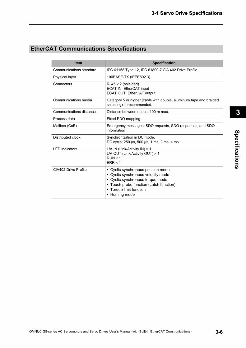
3-1 Servo Drive Specifications
3
Specifications
EtherCAT Communications Specifications
Item Specification
Communications standard IEC 61158 Type 12, IEC 61800-7 CiA 402 Drive Profile
Physical layer 100BASE-TX (IEEE802.3)
Connectors RJ45 × 2 (shielded)ECAT IN: EtherCAT inputECAT OUT: EtherCAT output
Communications media Category 5 or higher (cable with double, aluminum tape and braided shielding) is recommended.
Communications distance Distance between nodes: 100 m max.
Process data Fixed PDO mapping
Mailbox (CoE) Emergency messages, SDO requests, SDO responses, and SDO information
Distributed clock Synchronization in DC mode.DC cycle: 250 µs, 500 µs, 1 ms, 2 ms, 4 ms
LED indicators L/A IN (Link/Activity IN) × 1L/A OUT (Link/Activity OUT) × 1RUN × 1ERR × 1
CiA402 Drive Profile Cyclic synchronous position modeCyclic synchronous velocity modeCyclic synchronous torque modeTouch probe function (Latch function)Torque limit functionHoming mode
3-6OMNUC G5-series AC Servomotors and Servo Drives User’s Manual (with Built-in EtherCAT Communications)
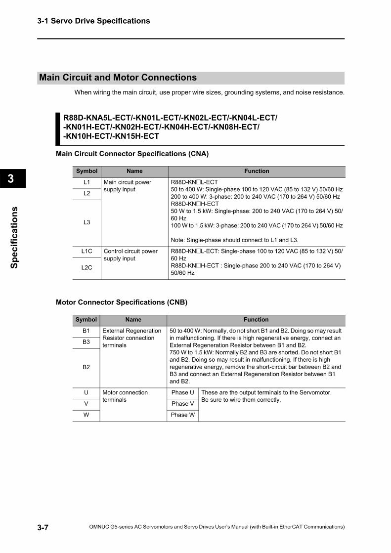
3-1 Servo Drive Specifications
3
Spec
ifica
tions
Main Circuit and Motor ConnectionsWhen wiring the main circuit, use proper wire sizes, grounding systems, and noise resistance.
R88D-KNA5L-ECT/-KN01L-ECT/-KN02L-ECT/-KN04L-ECT/-KN01H-ECT/-KN02H-ECT/-KN04H-ECT/-KN08H-ECT/-KN10H-ECT/-KN15H-ECT
Main Circuit Connector Specifications (CNA)
Motor Connector Specifications (CNB)
Symbol Name Function
L1 Main circuit power supply input
R88D-KN@L-ECT50 to 400 W: Single-phase 100 to 120 VAC (85 to 132 V) 50/60 Hz200 to 400 W: 3-phase: 200 to 240 VAC (170 to 264 V) 50/60 HzR88D-KN@H-ECT50 W to 1.5 kW: Single-phase: 200 to 240 VAC (170 to 264 V) 50/60 Hz100 W to 1.5 kW: 3-phase: 200 to 240 VAC (170 to 264 V) 50/60 Hz
Note: Single-phase should connect to L1 and L3.
L2
L3
L1C Control circuit power supply input
R88D-KN@L-ECT: Single-phase 100 to 120 VAC (85 to 132 V) 50/60 HzR88D-KN@H-ECT : Single-phase 200 to 240 VAC (170 to 264 V) 50/60 Hz
L2C
Symbol Name Function
B1 External Regeneration Resistor connection terminals
50 to 400 W: Normally, do not short B1 and B2. Doing so may result in malfunctioning. If there is high regenerative energy, connect an External Regeneration Resistor between B1 and B2.750 W to 1.5 kW: Normally B2 and B3 are shorted. Do not short B1 and B2. Doing so may result in malfunctioning. If there is high regenerative energy, remove the short-circuit bar between B2 and B3 and connect an External Regeneration Resistor between B1 and B2.
B3
B2
U Motor connection terminals
Phase U These are the output terminals to the Servomotor.Be sure to wire them correctly.
V Phase V
W Phase W
3-7 OMNUC G5-series AC Servomotors and Servo Drives User’s Manual (with Built-in EtherCAT Communications)
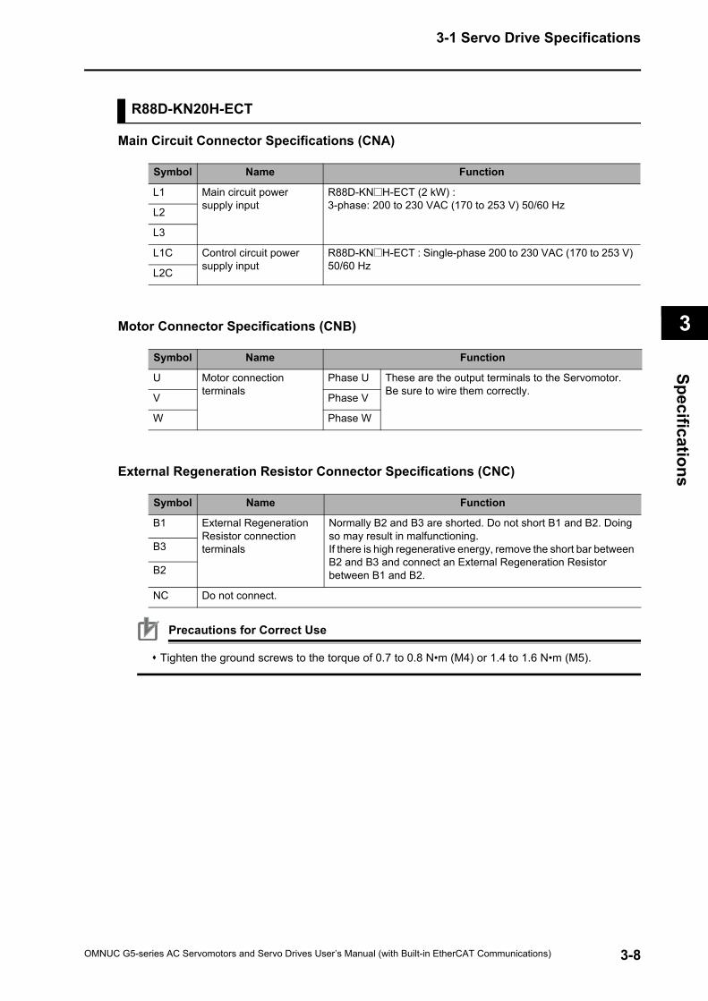
3-1 Servo Drive Specifications
3
Specifications
R88D-KN20H-ECT
Main Circuit Connector Specifications (CNA)
Motor Connector Specifications (CNB)
External Regeneration Resistor Connector Specifications (CNC)
Precautions for Correct Use
Tighten the ground screws to the torque of 0.7 to 0.8 N•m (M4) or 1.4 to 1.6 N•m (M5).
Symbol Name Function
L1 Main circuit power supply input
R88D-KN@H-ECT (2 kW) : 3-phase: 200 to 230 VAC (170 to 253 V) 50/60 Hz
L2
L3
L1C Control circuit power supply input
R88D-KN@H-ECT : Single-phase 200 to 230 VAC (170 to 253 V) 50/60 Hz
L2C
Symbol Name Function
U Motor connection terminals
Phase U These are the output terminals to the Servomotor.Be sure to wire them correctly.
V Phase V
W Phase W
Symbol Name Function
B1 External Regeneration Resistor connection terminals
Normally B2 and B3 are shorted. Do not short B1 and B2. Doing so may result in malfunctioning.If there is high regenerative energy, remove the short bar between B2 and B3 and connect an External Regeneration Resistor between B1 and B2.
B3
B2
NC Do not connect.
3-8OMNUC G5-series AC Servomotors and Servo Drives User’s Manual (with Built-in EtherCAT Communications)
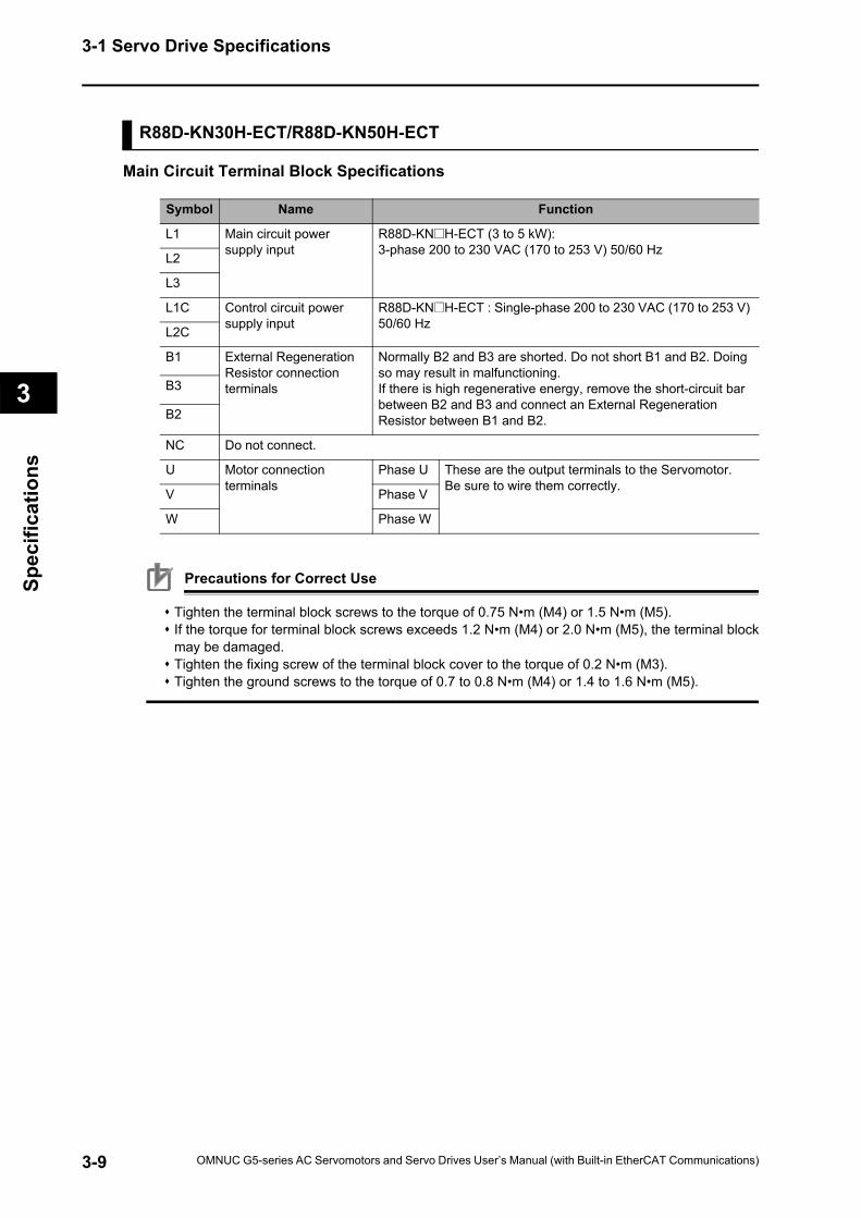
3-1 Servo Drive Specifications
3
Spec
ifica
tions
R88D-KN30H-ECT/R88D-KN50H-ECT
Main Circuit Terminal Block Specifications
Precautions for Correct Use
Tighten the terminal block screws to the torque of 0.75 N•m (M4) or 1.5 N•m (M5).If the torque for terminal block screws exceeds 1.2 N•m (M4) or 2.0 N•m (M5), the terminal blockmay be damaged.Tighten the fixing screw of the terminal block cover to the torque of 0.2 N•m (M3).Tighten the ground screws to the torque of 0.7 to 0.8 N•m (M4) or 1.4 to 1.6 N•m (M5).
Symbol Name Function
L1 Main circuit power supply input
R88D-KN@H-ECT (3 to 5 kW):3-phase 200 to 230 VAC (170 to 253 V) 50/60 Hz
L2
L3
L1C Control circuit power supply input
R88D-KN@H-ECT : Single-phase 200 to 230 VAC (170 to 253 V) 50/60 Hz
L2C
B1 External Regeneration Resistor connection terminals
Normally B2 and B3 are shorted. Do not short B1 and B2. Doing so may result in malfunctioning.If there is high regenerative energy, remove the short-circuit bar between B2 and B3 and connect an External Regeneration Resistor between B1 and B2.
B3
B2
NC Do not connect.
U Motor connection terminals
Phase U These are the output terminals to the Servomotor.Be sure to wire them correctly.
V Phase V
W Phase W
3-9 OMNUC G5-series AC Servomotors and Servo Drives User’s Manual (with Built-in EtherCAT Communications)
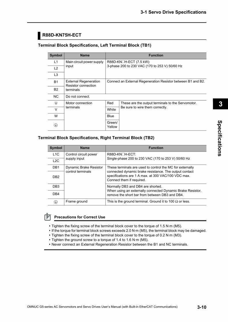
3-1 Servo Drive Specifications
3
Specifications
R88D-KN75H-ECT
Terminal Block Specifications, Left Terminal Block (TB1)
Terminal Block Specifications, Right Terminal Block (TB2)
Precautions for Correct Use
Tighten the fixing screw of the terminal block cover to the torque of 1.5 N·m (M5).If the torque for terminal block screws exceeds 2.0 N·m (M5), the terminal block may be damaged.Tighten the fixing screw of the terminal block cover to the torque of 0.2 N·m (M3).Tighten the ground screw to a torque of 1.4 to 1.6 N·m (M5).Never connect an External Regeneration Resistor between the B1 and NC terminals.
Symbol Name Function
L1 Main circuit power supply input
R88D-KN@H-ECT (7.5 kW): 3-phase 200 to 230 VAC (170 to 253 V) 50/60 Hz
L2
L3
B1 External Regeneration Resistor connection terminals
Connect an External Regeneration Resistor between B1 and B2.
B2
NC Do not connect.
U Motor connection terminals
Red These are the output terminals to the Servomotor.Be sure to wire them correctly.
V White
W Blue
Green/Yellow
Symbol Name Function
L1C Control circuit power supply input
R88D-KN@H-ECT: Single-phase 200 to 230 VAC (170 to 253 V) 50/60 Hz
L2C
DB1 Dynamic Brake Resistor control terminals
These terminals are used to control the MC for externally connected dynamic brake resistance. The output contact specifications are 1 A max. at 300 VAC/100 VDC max.Connect them if required.
DB2
DB3 Normally DB3 and DB4 are shorted.When using an externally connected Dynamic Brake Resistor, remove the short bar from between DB3 and DB4.DB4
Frame ground This is the ground terminal. Ground it to 100 Ω or less.
3-10OMNUC G5-series AC Servomotors and Servo Drives User’s Manual (with Built-in EtherCAT Communications)
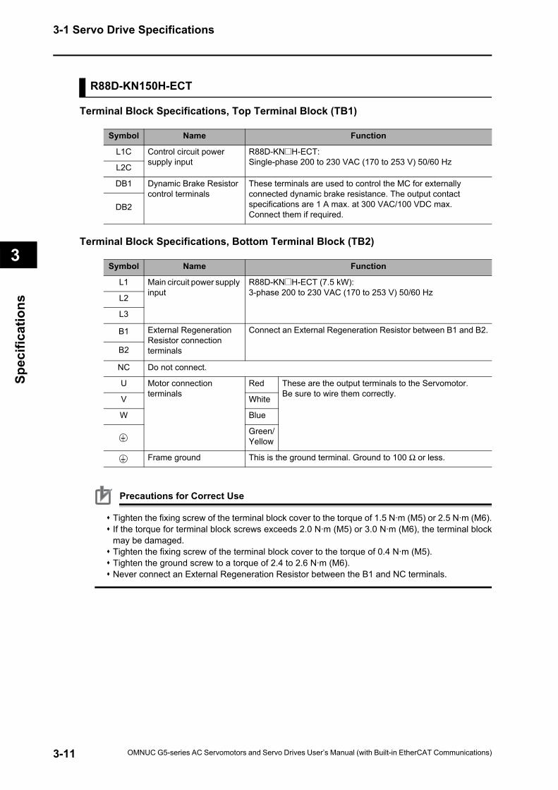
3-1 Servo Drive Specifications
3
Spec
ifica
tions
R88D-KN150H-ECT
Terminal Block Specifications, Top Terminal Block (TB1)
Terminal Block Specifications, Bottom Terminal Block (TB2)
Precautions for Correct Use
Tighten the fixing screw of the terminal block cover to the torque of 1.5 N·m (M5) or 2.5 N·m (M6).If the torque for terminal block screws exceeds 2.0 N·m (M5) or 3.0 N·m (M6), the terminal blockmay be damaged.Tighten the fixing screw of the terminal block cover to the torque of 0.4 N·m (M5).Tighten the ground screw to a torque of 2.4 to 2.6 N·m (M6).Never connect an External Regeneration Resistor between the B1 and NC terminals.
Symbol Name Function
L1C Control circuit power supply input
R88D-KN@H-ECT: Single-phase 200 to 230 VAC (170 to 253 V) 50/60 Hz
L2C
DB1 Dynamic Brake Resistor control terminals
These terminals are used to control the MC for externally connected dynamic brake resistance. The output contact specifications are 1 A max. at 300 VAC/100 VDC max.Connect them if required.
DB2
Symbol Name Function
L1 Main circuit power supply input
R88D-KN@H-ECT (7.5 kW): 3-phase 200 to 230 VAC (170 to 253 V) 50/60 Hz
L2
L3
B1 External Regeneration Resistor connection terminals
Connect an External Regeneration Resistor between B1 and B2.
B2
NC Do not connect.
U Motor connection terminals
Red These are the output terminals to the Servomotor.Be sure to wire them correctly.
V White
W Blue
Green/Yellow
Frame ground This is the ground terminal. Ground to 100 Ω or less.
3-11 OMNUC G5-series AC Servomotors and Servo Drives User’s Manual (with Built-in EtherCAT Communications)
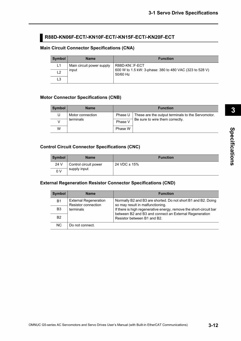
3-1 Servo Drive Specifications
3
Specifications
R88D-KN06F-ECT/-KN10F-ECT/-KN15F-ECT/-KN20F-ECT
Main Circuit Connector Specifications (CNA)
Motor Connector Specifications (CNB)
Control Circuit Connector Specifications (CNC)
External Regeneration Resistor Connector Specifications (CND)
Symbol Name Function
L1 Main circuit power supply input
R88D-KN@F-ECT600 W to 1.5 kW: 3-phase: 380 to 480 VAC (323 to 528 V) 50/60 HzL2
L3
Symbol Name Function
U Motor connection terminals
Phase U These are the output terminals to the Servomotor.Be sure to wire them correctly.
V Phase V
W Phase W
Symbol Name Function
24 V Control circuit power supply input
24 VDC ± 15%
0 V
Symbol Name Function
B1 External Regeneration Resistor connection terminals
Normally B2 and B3 are shorted. Do not short B1 and B2. Doing so may result in malfunctioning.If there is high regenerative energy, remove the short-circuit bar between B2 and B3 and connect an External Regeneration Resistor between B1 and B2.
B3
B2
NC Do not connect.
3-12OMNUC G5-series AC Servomotors and Servo Drives User’s Manual (with Built-in EtherCAT Communications)
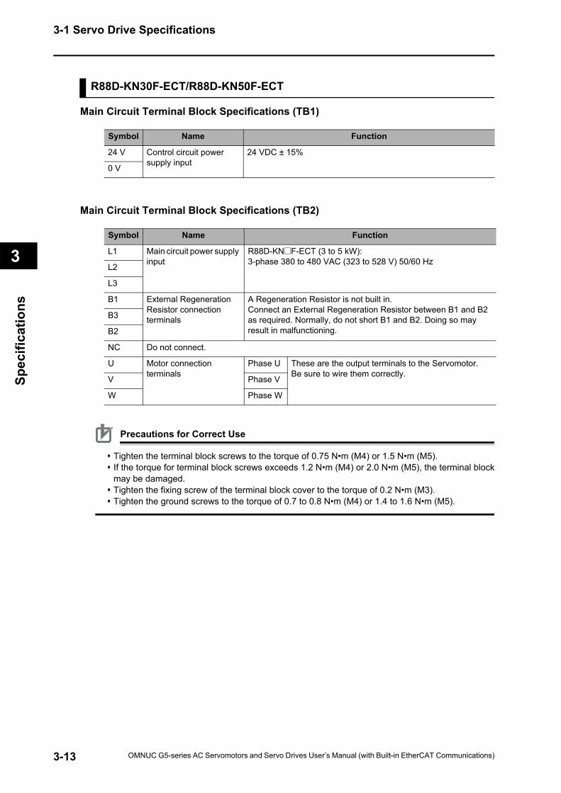
3-1 Servo Drive Specifications
3
Spec
ifica
tions
R88D-KN30F-ECT/R88D-KN50F-ECT
Main Circuit Terminal Block Specifications (TB1)
Main Circuit Terminal Block Specifications (TB2)
Precautions for Correct Use
Tighten the terminal block screws to the torque of 0.75 N•m (M4) or 1.5 N•m (M5).If the torque for terminal block screws exceeds 1.2 N•m (M4) or 2.0 N•m (M5), the terminal blockmay be damaged.Tighten the fixing screw of the terminal block cover to the torque of 0.2 N•m (M3).Tighten the ground screws to the torque of 0.7 to 0.8 N•m (M4) or 1.4 to 1.6 N•m (M5).
Symbol Name Function
24 V Control circuit power supply input
24 VDC ± 15%
0 V
Symbol Name Function
L1 Main circuit power supply input
R88D-KN@F-ECT (3 to 5 kW):3-phase 380 to 480 VAC (323 to 528 V) 50/60 Hz
L2
L3
B1 External Regeneration Resistor connection terminals
A Regeneration Resistor is not built in.Connect an External Regeneration Resistor between B1 and B2 as required. Normally, do not short B1 and B2. Doing so may result in malfunctioning.
B3
B2
NC Do not connect.
U Motor connection terminals
Phase U These are the output terminals to the Servomotor.Be sure to wire them correctly.
V Phase V
W Phase W
3-13 OMNUC G5-series AC Servomotors and Servo Drives User’s Manual (with Built-in EtherCAT Communications)
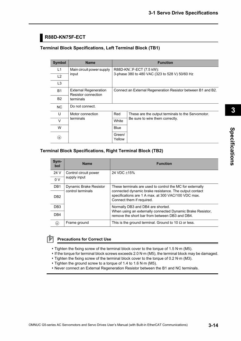
3-1 Servo Drive Specifications
3
Specifications
R88D-KN75F-ECT
Terminal Block Specifications, Left Terminal Block (TB1)
Terminal Block Specifications, Right Terminal Block (TB2)
Precautions for Correct Use
Tighten the fixing screw of the terminal block cover to the torque of 1.5 N·m (M5).If the torque for terminal block screws exceeds 2.0 N·m (M5), the terminal block may be damaged.Tighten the fixing screw of the terminal block cover to the torque of 0.2 N·m (M3).Tighten the ground screw to a torque of 1.4 to 1.6 N·m (M5).Never connect an External Regeneration Resistor between the B1 and NC terminals.
Symbol Name Function
L1 Main circuit power supply input
R88D-KN@F-ECT (7.5 kW): 3-phase 380 to 480 VAC (323 to 528 V) 50/60 Hz
L2
L3
B1 External Regeneration Resistor connection terminals
Connect an External Regeneration Resistor between B1 and B2.
B2
NC Do not connect.
U Motor connection terminals
Red These are the output terminals to the Servomotor.Be sure to wire them correctly.
V White
W Blue
Green/Yellow
Sym-bol Name Function
24 V Control circuit power supply input
24 VDC ±15%
0 V
DB1 Dynamic Brake Resistor control terminals
These terminals are used to control the MC for externally connected dynamic brake resistance. The output contact specifications are 1 A max. at 300 VAC/100 VDC max.Connect them if required.
DB2
DB3 Normally DB3 and DB4 are shorted.When using an externally connected Dynamic Brake Resistor, remove the short bar from between DB3 and DB4.DB4
Frame ground This is the ground terminal. Ground to 10 Ω or less.
3-14OMNUC G5-series AC Servomotors and Servo Drives User’s Manual (with Built-in EtherCAT Communications)
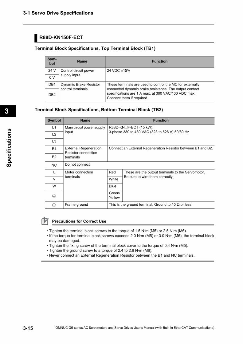
3-1 Servo Drive Specifications
3
Spec
ifica
tions
R88D-KN150F-ECT
Terminal Block Specifications, Top Terminal Block (TB1)
Terminal Block Specifications, Bottom Terminal Block (TB2)
Precautions for Correct Use
Tighten the terminal block screws to the torque of 1.5 N·m (M5) or 2.5 N·m (M6).If the torque for terminal block screws exceeds 2.0 N·m (M5) or 3.0 N·m (M6), the terminal blockmay be damaged.Tighten the fixing screw of the terminal block cover to the torque of 0.4 N·m (M5).Tighten the ground screw to a torque of 2.4 to 2.6 N·m (M6).Never connect an External Regeneration Resistor between the B1 and NC terminals.
Sym-bol Name Function
24 V Control circuit power supply input
24 VDC ±15%
0 V
DB1 Dynamic Brake Resistor control terminals
These terminals are used to control the MC for externally connected dynamic brake resistance. The output contact specifications are 1 A max. at 300 VAC/100 VDC max.Connect them if required.
DB2
Symbol Name Function
L1 Main circuit power supply input
R88D-KN@F-ECT (15 kW): 3-phase 380 to 480 VAC (323 to 528 V) 50/60 Hz
L2
L3
B1 External Regeneration Resistor connection terminals
Connect an External Regeneration Resistor between B1 and B2.
B2
NC Do not connect.
U Motor connection terminals
Red These are the output terminals to the Servomotor.Be sure to wire them correctly.
V White
W Blue
Green/Yellow
Frame ground This is the ground terminal. Ground to 10 Ω or less.
3-15 OMNUC G5-series AC Servomotors and Servo Drives User’s Manual (with Built-in EtherCAT Communications)
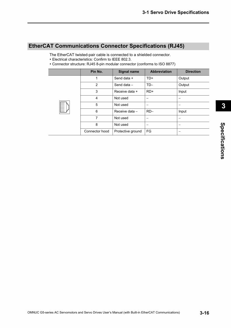
3-1 Servo Drive Specifications
3
Specifications
EtherCAT Communications Connector Specifications (RJ45)The EtherCAT twisted-pair cable is connected to a shielded connector.
Electrical characteristics: Confirm to IEEE 802.3.Connector structure: RJ45 8-pin modular connector (conforms to ISO 8877)
Pin No. Signal name Abbreviation Direction
1 Send data + TD+ Output
2 Send data − TD− Output
3 Receive data + RD+ Input
4 Not used − −
5 Not used − −
6 Receive data − RD− Input
7 Not used − −
8 Not used − −
Connector hood Protective ground FG −
3-16OMNUC G5-series AC Servomotors and Servo Drives User’s Manual (with Built-in EtherCAT Communications)
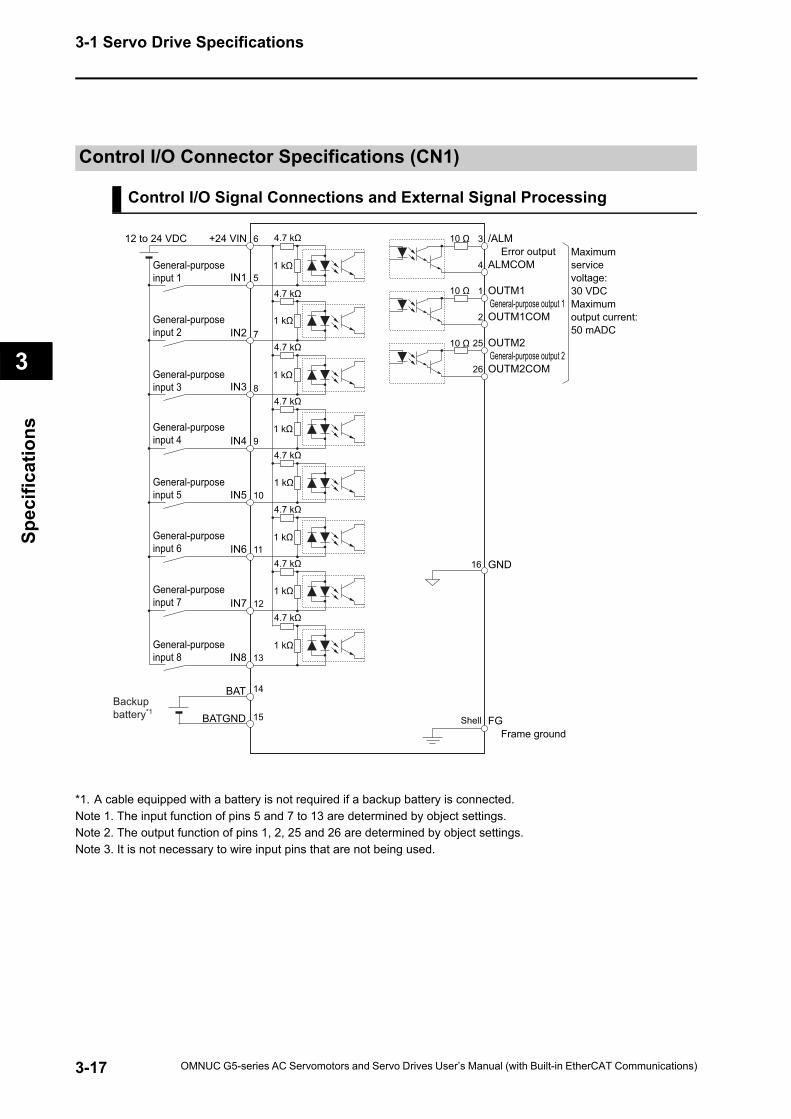
3-1 Servo Drive Specifications
3
Spec
ifica
tions
Control I/O Connector Specifications (CN1)
Control I/O Signal Connections and External Signal Processing
*1. A cable equipped with a battery is not required if a backup battery is connected.Note 1. The input function of pins 5 and 7 to 13 are determined by object settings.Note 2. The output function of pins 1, 2, 25 and 26 are determined by object settings.Note 3. It is not necessary to wire input pins that are not being used.
General-purposeinput 1
/ALMError output
General-purpose output 1
General-purpose output 2
ALMCOM
3
4
OUTM1
OUTM1COM
OUTM2COM
1
2
OUTM225
26
12IN7
11IN6
10IN5
9IN4
8IN3
7IN2
5IN1
6+24 VIN
General-purposeinput 7
General-purposeinput 6
General-purposeinput 5
General-purposeinput 4
General-purposeinput 3
General-purposeinput 2
12 to 24 VDCMaximum service voltage:30 VDC Maximum output current:50 mADC
13IN8General-purposeinput 8
Frame groundFGShell
4.7 kΩ
4.7 kΩ
4.7 kΩ
4.7 kΩ
4.7 kΩ
4.7 kΩ
4.7 kΩ
BAT
BATGNDBackupbattery*1
14
15
1 kΩ
4.7 kΩ
1 kΩ
1 kΩ
1 kΩ
1 kΩ
1 kΩ
1 kΩ
1 kΩ
16 GND
10 Ω
10 Ω
10 Ω
3-17 OMNUC G5-series AC Servomotors and Servo Drives User’s Manual (with Built-in EtherCAT Communications)
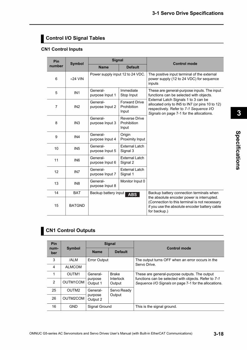
3-1 Servo Drive Specifications
3
Specifications
Control I/O Signal Tables
CN1 Control Inputs
CN1 Control Outputs
Pin number Symbol
SignalControl mode
Name Default
6 +24 VINPower supply input 12 to 24 VDC. The positive input terminal of the external
power supply (12 to 24 VDC) for sequence inputs
5 IN1 General-purpose Input 1
Immediate Stop Input
These are general-purpose inputs. The input functions can be selected with objects. External Latch Signals 1 to 3 can be allocated only to IN5 to IN7 (or pins 10 to 12) respectively. Refer to 7-1 Sequence I/O Signals on page 7-1 for the allocations.
7 IN2General-purpose Input 2
Forward Drive Prohibition Input
8 IN3General-purpose Input 3
Reverse Drive Prohibition Input
9 IN4 General-purpose Input 4
Origin Proximity Input
10 IN5 General-purpose Input 5
External Latch Signal 3
11 IN6 General-purpose Input 6
External Latch Signal 2
12 IN7 General-purpose Input 7
External Latch Signal 1
13 IN8 General-purpose Input 8
Monitor Input 0
14 BAT Backup battery input Backup battery connection terminals when the absolute encoder power is interrupted. (Connection to this terminal is not necessary if you use the absolute encoder battery cable for backup.)
15 BATGND
ABS
Pin num-ber
SymbolSignal
Control modeName Default
3 /ALM Error Output The output turns OFF when an error occurs in the Servo Drive.
4 ALMCOM
1 OUTM1 General-purpose Output 1
Brake Interlock Output
These are general-purpose outputs. The output functions can be selected with objects. Refer to 7-1 Sequence I/O Signals on page 7-1 for the allocations.2 OUTM1COM
25 OUTM2 General-purpose Output 2
Servo Ready Output
26 OUTM2COM
16 GND Signal Ground This is the signal ground.
3-18OMNUC G5-series AC Servomotors and Servo Drives User’s Manual (with Built-in EtherCAT Communications)
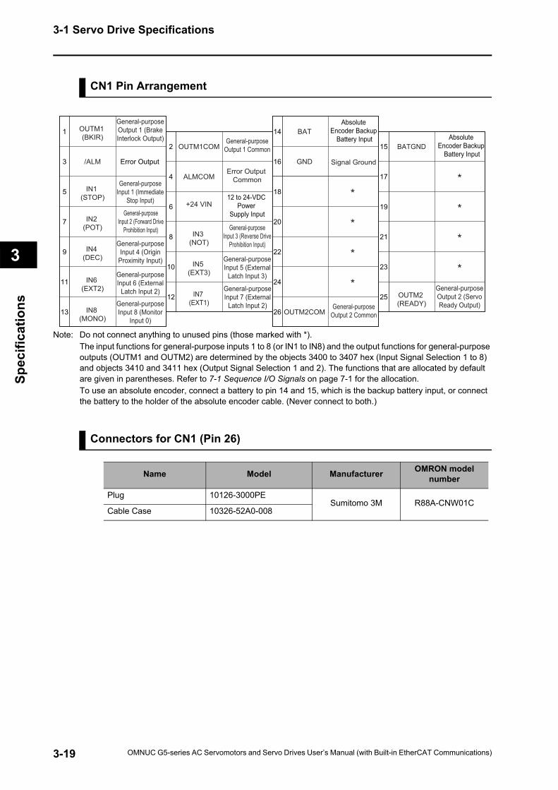
3-1 Servo Drive Specifications
3
Spec
ifica
tions
CN1 Pin Arrangement
Note: Do not connect anything to unused pins (those marked with *).The input functions for general-purpose inputs 1 to 8 (or IN1 to IN8) and the output functions for general-purpose outputs (OUTM1 and OUTM2) are determined by the objects 3400 to 3407 hex (Input Signal Selection 1 to 8) and objects 3410 and 3411 hex (Output Signal Selection 1 and 2). The functions that are allocated by default are given in parentheses. Refer to 7-1 Sequence I/O Signals on page 7-1 for the allocation.To use an absolute encoder, connect a battery to pin 14 and 15, which is the backup battery input, or connect the battery to the holder of the absolute encoder cable. (Never connect to both.)
Connectors for CN1 (Pin 26)
Name Model Manufacturer OMRON model number
Plug 10126-3000PESumitomo 3M R88A-CNW01C
Cable Case 10326-52A0-008
1
3
5
7
9
11
13
2
4
6
8
10
12
14
16
18
20
22
24
26
15
17
19
21
23
25
IN2 (POT)
IN1 (STOP)
OUTM1 (BKIR)
*
BAT
BATGND
OUTM2 (READY)
ALMCOM
/ALM
IN8 (MONO)
IN3 (NOT)
IN4 (DEC)
IN5 (EXT3)
IN6 (EXT2)
IN7 (EXT1)
OUTM1COM
*
GND
OUTM2COM
*
*
*
*
*
*
General-purposeOutput 2 Common
General-purposeOutput 1 Common
+24 VIN
Absolute Encoder Backup
Battery Input
Absolute Encoder Backup
Battery Input
12 to 24-VDC Power
Supply Input
Error Output Common
Error Output Signal Ground
General-purposeOutput 1 (Brake Interlock Output)
General-purposeInput 2 (Forward Drive
Prohibition Input) General-purposeInput 3 (Reverse Drive
Prohibition Input)
General-purposeOutput 2 (Servo Ready Output)
General-purposeInput 1 (Immediate
Stop Input)
General-purposeInput 4 (Origin
Proximity Input)
General-purposeInput 6 (External
Latch Input 2)
General-purposeInput 8 (Monitor
Input 0)
General-purposeInput 5 (External
Latch Input 3)
General-purposeInput 7 (External
Latch Input 2)
3-19 OMNUC G5-series AC Servomotors and Servo Drives User’s Manual (with Built-in EtherCAT Communications)
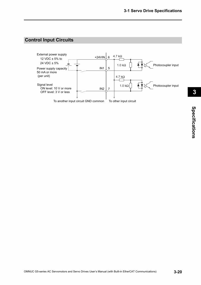
3-1 Servo Drive Specifications
3
Specifications
Control Input Circuits
4.7 kΩ
1.0 kΩ5
7
IN1
IN2
6+24VIN
To other input circuit
External power supply 12 VDC ± 5% to 24 VDC ± 5%
Power supply capacity 50 mA or more(per unit)
Signal level ON level: 10 V or more OFF level: 3 V or less
To another input circuit GND common
Photocoupler input
4.7 kΩ
1.0 kΩ Photocoupler input
3-20OMNUC G5-series AC Servomotors and Servo Drives User’s Manual (with Built-in EtherCAT Communications)
3-1 Servo Drive Specifications
3
Spec
ifica
tions
Control Input DetailsThis is the detailed information about the CN1 connector input pins.
General-purpose Inputs (IN1 to IN8)
Note: The functions that are allocated by default are given in brackets. Refer to 7-1 Sequence I/O Signals on page 7-1 for the allocation procedures.
Immediate Stop Input (STOP)STOP is used when an external sequence such as the host forcibly turns OFF the servo. If the input is turned OFF during the Servomotor rotation, the dynamic brake makes a decelerationstop. After the motor stops, it remains in servo-free state. If the Immediate Stop Input (STOP) turns ON when the motor is energized, an Immediate StopInput Error (Error No. 87.0) will occur.This input is allocated to the pin 5 with the default setting.
Precautions for Safe Use
Turn OFF the Immediate Stop Input (STOP) at the same time when you turn OFF the mainpower. When the main power turns OFF due to an external immediate stop, the motor willcontinues to rotate due to residual voltage. This may cause human injuries or damages to themachine and devices.
Pin 5: General-purpose Input 1 (IN1) [Immediate Stop Input (STOP)]
Pin 7: General-purpose Input 2 (IN2) [Forward Drive Prohibition Input (POT)]
Pin 8: General-purpose Input 3 (IN3) [Reverse Drive Prohibition Input (NOT)]
Pin 9: General-purpose Input 4 (IN4) [Origin Proximity Input (DEC)]
Pin 10: General-purpose Input 5 (IN5) [External Latch Input 3 (EXT3)]
Pin 11: General-purpose Input 6 (IN6) [External Latch Input 2 (EXT2)]
Pin 12: General-purpose Input 7 (IN7) [External Latch Input 1 (EXT1)]
Pin 13: General-purpose Input 8 (IN8) [Monitor Input 0 (MON0)]
3-21 OMNUC G5-series AC Servomotors and Servo Drives User’s Manual (with Built-in EtherCAT Communications)
3-1 Servo Drive Specifications
3
Specifications
]
Forward Drive Prohibition Input (POT) and Reverse Drive Prohibition Input (NOT)These two signals are the inputs to prohibit forward and reverse rotation (over-travel inputs).When these terminals are shorted (factory setting), the Servo Drive can rotate in the specifieddirection.In the drive prohibition state, Servomotor switches to servo lock state after a deceleration stop.The maximum torque for a deceleration stop is the same as the maximum Servomotor torque.In the drive prohibition state, the Servo Drive does not switch to an error state.When the Drive Prohibition Input Selection (3504 hex) is set to 1, the operation at a drive prohibitinput can be selected in the Stop Selection for Drive Prohibition Input (3505 hex).If the Drive Prohibition Input Selection (3504 hex) is set to 2, a Drive Prohibition Input Error (ErrorNo. 38.0) will occur when there is a drive prohibition input.With the default settings, the Forward Drive Prohibition Input (POT) is allocated to pin 7, and theReverse Drive Prohibition Input (NOT) is allocated to pin 8.
Precautions for Correct Use
Both signals are disabled (in a state in which drive prohibition will not operation) in the defaultsettings. If prohibiting the drive input is required, set the Drive Prohibit Input Selection (3504hex) to either 0 or 2. The setting on the Input Signal Selection 1 to 10 (3400 to 3409 hex) canchange the logic and allocation for the respective Input terminals (CN1 to 7 and 8).
Origin Proximity Input (DEC)This is the deceleration signal for origin returns.If the Origin Proximity Input turns ON while the Servomotor is traveling at the origin proximity inputsearch speed, it will decelerate to the Speed during search for zero (6099 hex).With the default settings, the Origin Proximity Input is assigned to pin 9.
External Latch Input Signals (EXT1, EXT2, and EXT3)These are the external input signals to latch the actual value in the feedback pulse counter.The encoder position data is obtained when the External Latch Input is turned ON.With the default settings, External Latch Input 1 is allocated to pin 12, External Latch Input 2 to pin11, and External Latch Input 3 to pin 10.
Precautions for Correct Use
The external latch inputs are detected by on the rising edge of the signal, but the minimal signalON and OFF widths must be 2 ms.The external latch inputs can only be set to NO (normally open) contacts.The external latch inputs can be allocated to pins 10 to 12 only.
3-22OMNUC G5-series AC Servomotors and Servo Drives User’s Manual (with Built-in EtherCAT Communications)
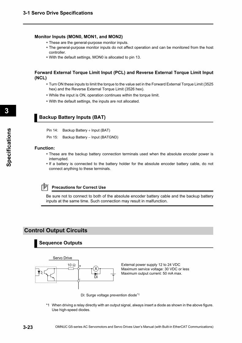
3-1 Servo Drive Specifications
3
Spec
ifica
tions
Monitor Inputs (MON0, MON1, and MON2)These are the general-purpose monitor inputs.The general-purpose monitor inputs do not affect operation and can be monitored from the hostcontroller. With the default settings, MON0 is allocated to pin 13.
Forward External Torque Limit Input (PCL) and Reverse External Torque Limit Input(NCL)
Turn ON these inputs to limit the torque to the value set in the Forward External Torque Limit (3525hex) and the Reverse External Torque Limit (3526 hex). While the input is ON, operation continues within the torque limit. With the default settings, the inputs are not allocated.
Backup Battery Inputs (BAT)
Function:These are the backup battery connection terminals used when the absolute encoder power isinterrupted.If a battery is connected to the battery holder for the absolute encoder battery cable, do notconnect anything to these terminals.
Precautions for Correct Use
Be sure not to connect to both of the absolute encoder battery cable and the backup batteryinputs at the same time. Such connection may result in malfunction.
Control Output Circuits
Sequence Outputs
*1 When driving a relay directly with an output signal, always insert a diode as shown in the above figure.Use high-speed diodes.
Pin 14: Backup Battery + Input (BAT)
Pin 15: Backup Battery − Input (BATGND)
-
X
Di
+
Di: Surge voltage prevention diode*1
External power supply 12 to 24 VDC Maximum service voltage: 30 VDC or less Maximum output current: 50 mA max.
Servo Drive
10 Ω
3-23 OMNUC G5-series AC Servomotors and Servo Drives User’s Manual (with Built-in EtherCAT Communications)
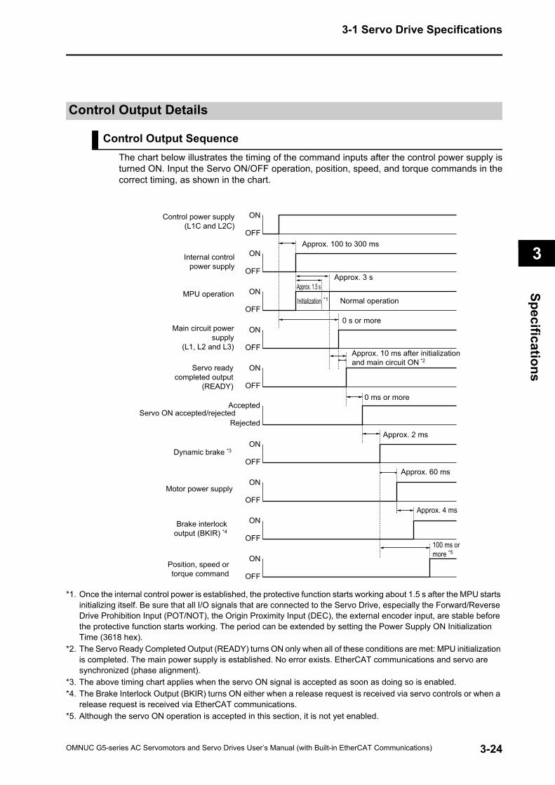
3-1 Servo Drive Specifications
3
Specifications
Control Output Details
Control Output SequenceThe chart below illustrates the timing of the command inputs after the control power supply isturned ON. Input the Servo ON/OFF operation, position, speed, and torque commands in thecorrect timing, as shown in the chart.
*1. Once the internal control power is established, the protective function starts working about 1.5 s after the MPU starts initializing itself. Be sure that all I/O signals that are connected to the Servo Drive, especially the Forward/Reverse Drive Prohibition Input (POT/NOT), the Origin Proximity Input (DEC), the external encoder input, are stable before the protective function starts working. The period can be extended by setting the Power Supply ON Initialization Time (3618 hex).
*2. The Servo Ready Completed Output (READY) turns ON only when all of these conditions are met: MPU initialization is completed. The main power supply is established. No error exists. EtherCAT communications and servo are synchronized (phase alignment).
*3. The above timing chart applies when the servo ON signal is accepted as soon as doing so is enabled. *4. The Brake Interlock Output (BKIR) turns ON either when a release request is received via servo controls or when a
release request is received via EtherCAT communications.*5. Although the servo ON operation is accepted in this section, it is not yet enabled.
Control power supply(L1C and L2C)
Internal controlpower supply
MPU operation
Main circuit powersupply
(L1, L2 and L3)
Servo readycompleted output
(READY)
Approx. 100 to 300 ms
Approx. 3 sApprox. 1.5 s
Initialization *1
Approx. 10 ms after initializationand main circuit ON *2
Dynamic brake *3
Motor power supply
Brake interlockoutput (BKIR) *4
Position, speed ortorque command
Approx. 60 ms
Approx. 2 ms
Approx. 4 ms
0 ms or more
0 s or more
100 ms ormore *5
ON
OFF
ON
OFF
ON
OFF
ON
OFF
ON
OFF
Servo ON accepted/rejected
ON
OFF
ON
OFF
ON
OFF
ON
OFF
Normal operation
Accepted
Rejected
3-24OMNUC G5-series AC Servomotors and Servo Drives User’s Manual (with Built-in EtherCAT Communications)
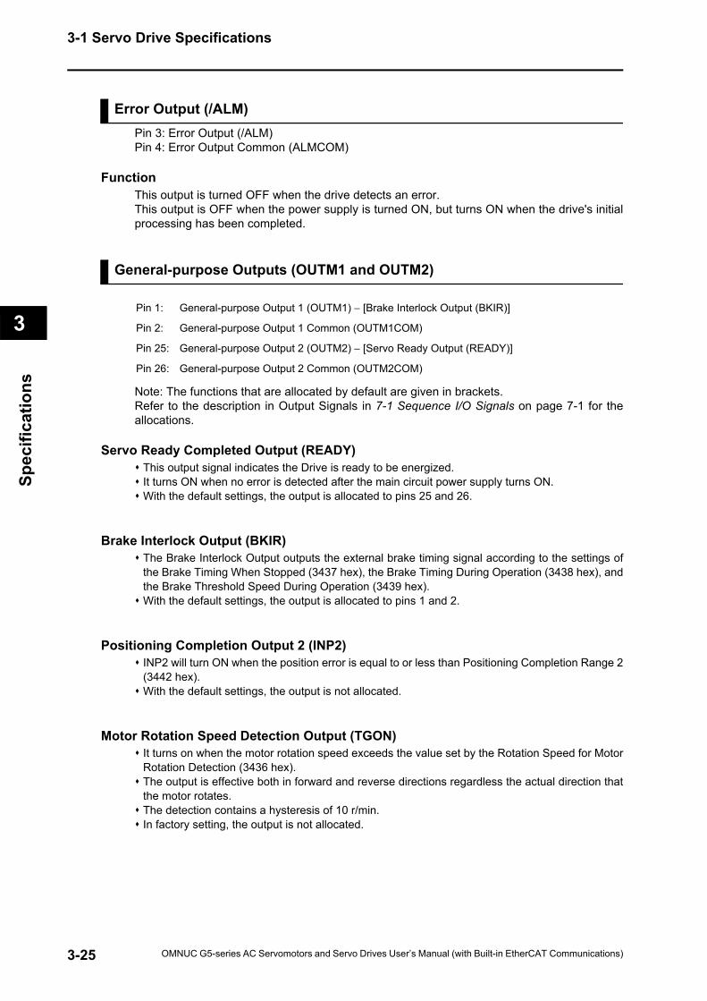
3-1 Servo Drive Specifications
3
Spec
ifica
tions
Error Output (/ALM)Pin 3: Error Output (/ALM)Pin 4: Error Output Common (ALMCOM)
FunctionThis output is turned OFF when the drive detects an error.This output is OFF when the power supply is turned ON, but turns ON when the drive's initialprocessing has been completed.
General-purpose Outputs (OUTM1 and OUTM2)
Note: The functions that are allocated by default are given in brackets. Refer to the description in Output Signals in 7-1 Sequence I/O Signals on page 7-1 for theallocations.
Servo Ready Completed Output (READY)This output signal indicates the Drive is ready to be energized.It turns ON when no error is detected after the main circuit power supply turns ON.With the default settings, the output is allocated to pins 25 and 26.
Brake Interlock Output (BKIR)The Brake Interlock Output outputs the external brake timing signal according to the settings ofthe Brake Timing When Stopped (3437 hex), the Brake Timing During Operation (3438 hex), andthe Brake Threshold Speed During Operation (3439 hex).With the default settings, the output is allocated to pins 1 and 2.
Positioning Completion Output 2 (INP2)INP2 will turn ON when the position error is equal to or less than Positioning Completion Range 2(3442 hex). With the default settings, the output is not allocated.
Motor Rotation Speed Detection Output (TGON)It turns on when the motor rotation speed exceeds the value set by the Rotation Speed for MotorRotation Detection (3436 hex).The output is effective both in forward and reverse directions regardless the actual direction thatthe motor rotates.The detection contains a hysteresis of 10 r/min.In factory setting, the output is not allocated.
Pin 1: General-purpose Output 1 (OUTM1) − [Brake Interlock Output (BKIR)]
Pin 2: General-purpose Output 1 Common (OUTM1COM)
Pin 25: General-purpose Output 2 (OUTM2) − [Servo Ready Output (READY)]
Pin 26: General-purpose Output 2 Common (OUTM2COM)
3-25 OMNUC G5-series AC Servomotors and Servo Drives User’s Manual (with Built-in EtherCAT Communications)
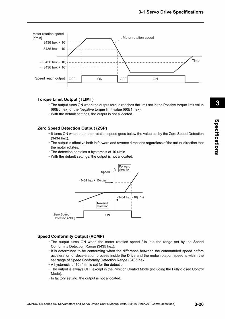
3-1 Servo Drive Specifications
3
Specifications
Torque Limit Output (TLIMT)The output turns ON when the output torque reaches the limit set in the Positive torque limit value(60E0 hex) or the Negative torque limit value (60E1 hex).With the default settings, the output is not allocated.
Zero Speed Detection Output (ZSP)It turns ON when the motor rotation speed goes below the value set by the Zero Speed Detection(3434 hex).The output is effective both in forward and reverse directions regardless of the actual direction thatthe motor rotates.The detection contains a hysteresis of 10 r/min.With the default settings, the output is not allocated.
Speed Conformity Output (VCMP)The output turns ON when the motor rotation speed fills into the range set by the SpeedConformity Detection Range (3435 hex). It is determined to be conforming when the difference between the commanded speed beforeacceleration or deceleration process inside the Drive and the motor rotation speed is within theset range of Speed Conformity Detection Range (3435 hex).A hysteresis of 10 r/min is set for the detection.The output is always OFF except in the Position Control Mode (including the Fully-closed ControlMode).In factory setting, the output is not allocated.
Motor rotation speed [r/min] Motor rotation speed
Time
3436 hex + 10
Speed reach output
3436 hex − 10
− (3436 hex − 10)− (3436 hex + 10)
OFF OFFON ON
Speed
Reversedirection
ON
(3434 hex + 10) r/min
Forwarddirection
(3434 hex - 10) r/min
Zero Speed Detection (ZSP)
3-26OMNUC G5-series AC Servomotors and Servo Drives User’s Manual (with Built-in EtherCAT Communications)
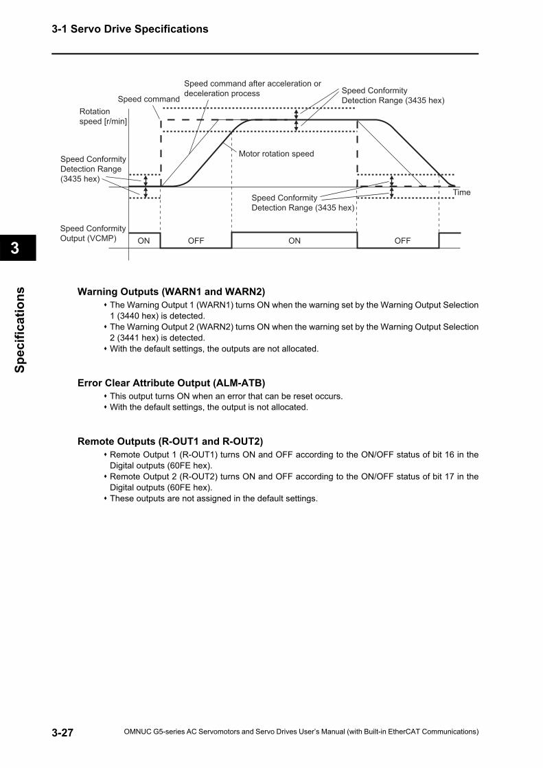
3-1 Servo Drive Specifications
3
Spec
ifica
tions
Warning Outputs (WARN1 and WARN2)The Warning Output 1 (WARN1) turns ON when the warning set by the Warning Output Selection1 (3440 hex) is detected.The Warning Output 2 (WARN2) turns ON when the warning set by the Warning Output Selection2 (3441 hex) is detected.With the default settings, the outputs are not allocated.
Error Clear Attribute Output (ALM-ATB)This output turns ON when an error that can be reset occurs.With the default settings, the output is not allocated.
Remote Outputs (R-OUT1 and R-OUT2)Remote Output 1 (R-OUT1) turns ON and OFF according to the ON/OFF status of bit 16 in theDigital outputs (60FE hex). Remote Output 2 (R-OUT2) turns ON and OFF according to the ON/OFF status of bit 17 in theDigital outputs (60FE hex). These outputs are not assigned in the default settings.
Rotation speed [r/min]
Speed command after acceleration or deceleration process
Speed command
Motor rotation speed
ON ONOFF OFF
Speed Conformity Detection Range (3435 hex)
Speed Conformity Detection Range (3435 hex)
Speed Conformity Detection Range (3435 hex)
Time
Speed Conformity Output (VCMP)
3-27 OMNUC G5-series AC Servomotors and Servo Drives User’s Manual (with Built-in EtherCAT Communications)
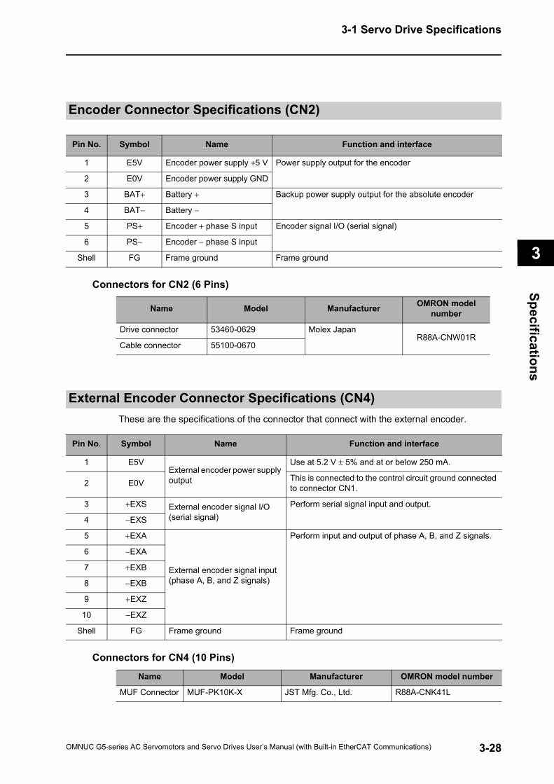
3-1 Servo Drive Specifications
3
Specifications
Encoder Connector Specifications (CN2)
Connectors for CN2 (6 Pins)
External Encoder Connector Specifications (CN4)These are the specifications of the connector that connect with the external encoder.
Connectors for CN4 (10 Pins)
Pin No. Symbol Name Function and interface
1 E5V Encoder power supply +5 V Power supply output for the encoder
2 E0V Encoder power supply GND
3 BAT+ Battery + Backup power supply output for the absolute encoder
4 BAT− Battery −
5 PS+ Encoder + phase S input Encoder signal I/O (serial signal)
6 PS− Encoder − phase S input
Shell FG Frame ground Frame ground
Name Model Manufacturer OMRON model number
Drive connector 53460-0629 Molex JapanR88A-CNW01R
Cable connector 55100-0670
Pin No. Symbol Name Function and interface
1 E5VExternal encoder power supply output
Use at 5.2 V ± 5% and at or below 250 mA.
2 E0V This is connected to the control circuit ground connected to connector CN1.
3 +EXS External encoder signal I/O(serial signal)
Perform serial signal input and output.
4 −EXS
5 +EXA
External encoder signal input(phase A, B, and Z signals)
Perform input and output of phase A, B, and Z signals.
6 −EXA
7 +EXB
8 −EXB
9 +EXZ
10 −EXZ
Shell FG Frame ground Frame ground
Name Model Manufacturer OMRON model number
MUF Connector MUF-PK10K-X JST Mfg. Co., Ltd. R88A-CNK41L
3-28OMNUC G5-series AC Servomotors and Servo Drives User’s Manual (with Built-in EtherCAT Communications)
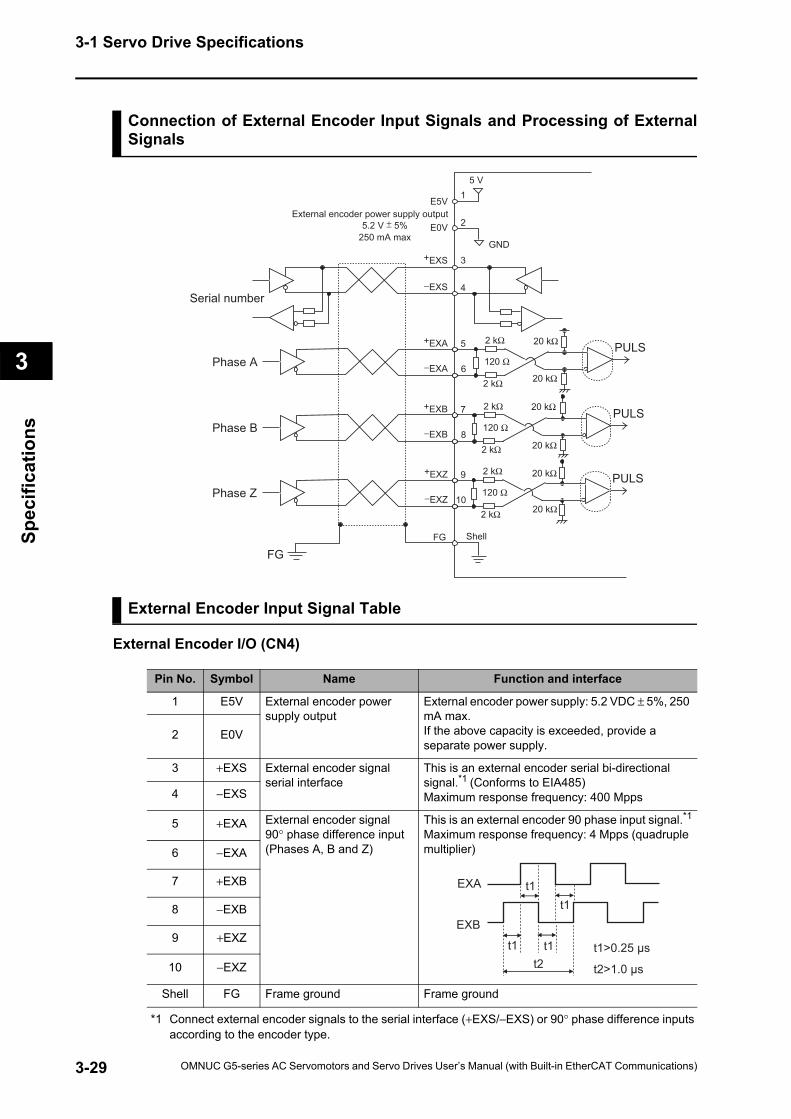
3-1 Servo Drive Specifications
3
Spec
ifica
tions
Connection of External Encoder Input Signals and Processing of ExternalSignals
External Encoder Input Signal Table
External Encoder I/O (CN4)
*1 Connect external encoder signals to the serial interface (+EXS/−EXS) or 90° phase difference inputs according to the encoder type.
Phase APULS+EXA
+EXS
E0V
E5V
5 V
−EXS
−EXA
5
1
2
3
4
62 kΩ
Phase B
+EXB
−EXB
7
8
Phase Z
+EXZ
−EXZ
9
10
ShellFG
FG
GND
External encoder power supply output5.2 V ± 5%
250 mA max
Serial number
120 Ω
2 kΩ
PULS
2 kΩ
120 Ω
2 kΩ
PULS
2 kΩ
120 Ω
2 kΩ
20 kΩ
20 kΩ
20 kΩ
20 kΩ
20 kΩ
20 kΩ
Pin No. Symbol Name Function and interface
1 E5V External encoder power supply output
External encoder power supply: 5.2 VDC ± 5%, 250 mA max.If the above capacity is exceeded, provide a separate power supply.
2 E0V
3 +EXS External encoder signal serial interface
This is an external encoder serial bi-directional signal.*1 (Conforms to EIA485)Maximum response frequency: 400 Mpps4 −EXS
5 +EXA External encoder signal90° phase difference input(Phases A, B and Z)
This is an external encoder 90 phase input signal.*1Maximum response frequency: 4 Mpps (quadruple multiplier)6 −EXA
7 +EXB
8 −EXB
9 +EXZ
10 −EXZ
Shell FG Frame ground Frame ground
EXA
EXB
t1 t1
t1t1
t2t1>0.25 μs
t2>1.0 μs
3-29 OMNUC G5-series AC Servomotors and Servo Drives User’s Manual (with Built-in EtherCAT Communications)
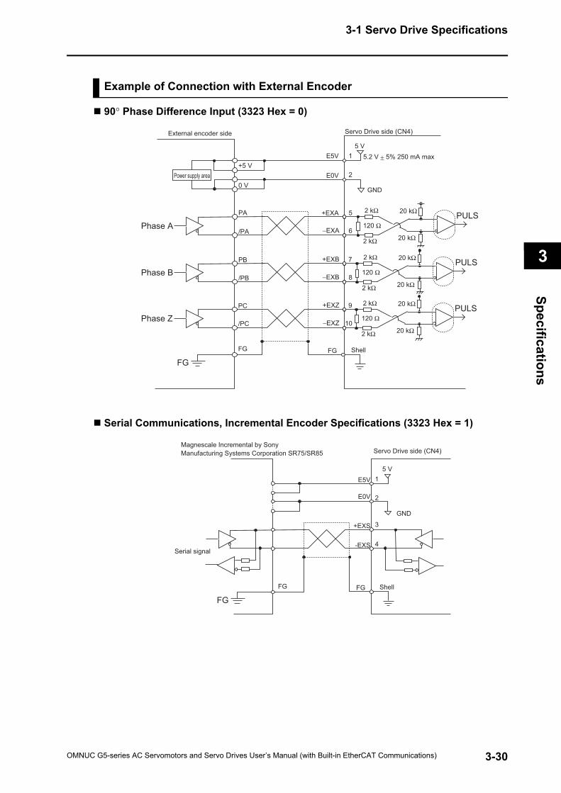
3-1 Servo Drive Specifications
3
Specifications
Example of Connection with External Encoder
90° Phase Difference Input (3323 Hex = 0)
Serial Communications, Incremental Encoder Specifications (3323 Hex = 1)
5.2 V ± 5% 250 mA max
Phase Z+EXZ
−EXZ
9
10
Phase A −EXA
+EXA
GND
E5V5 V
E0V
6
5
2
1
Phase B+EXB
−EXB
7
8
ShellFG
FG
+5 V
0 V
PA
/PA
PB
/PB
PC
/PC
FG
Servo Drive side (CN4)External encoder side
Power supply area
PULS20 kΩ
2 kΩ 20 kΩ
120 Ω
2 kΩ
PULS20 kΩ
2 kΩ 20 kΩ
120 Ω
2 kΩ
PULS20 kΩ
2 kΩ 20 kΩ
120 Ω
2 kΩ
+EXS
-EXS
GND
E5V5 V
E0V 2
3
4
1
ShellFG
Servo Drive side (CN4)
FG
FG
Serial signal
Magnescale Incremental by Sony Manufacturing Systems Corporation SR75/SR85
3-30OMNUC G5-series AC Servomotors and Servo Drives User’s Manual (with Built-in EtherCAT Communications)
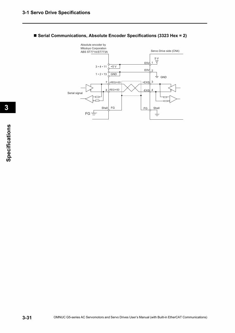
3-1 Servo Drive Specifications
3
Spec
ifica
tions
Serial Communications, Absolute Encoder Specifications (3323 Hex = 2)
+EXS+REQ/+SD
-REQ/+SD -EXS
GNDGND
E5V5 V
E0V 2
37
8 4
1
ShellShell FG
Servo Drive side (CN4)
FG
FG
Serial signal
Absolute encoder by Mitutoyo Corporation ABS ST771A/ST773A
+5 V3 • 4 • 11
1 • 2 • 13
3-31 OMNUC G5-series AC Servomotors and Servo Drives User’s Manual (with Built-in EtherCAT Communications)
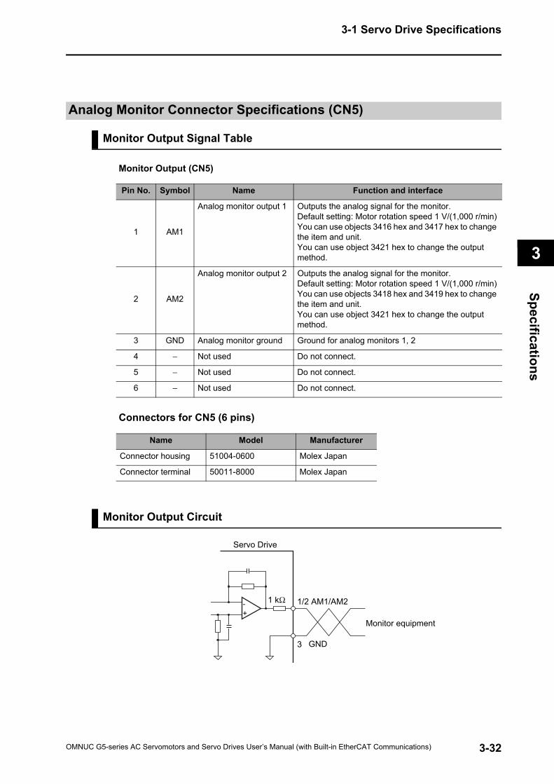
3-1 Servo Drive Specifications
3
Specifications
Analog Monitor Connector Specifications (CN5)
Monitor Output Signal Table
Monitor Output (CN5)
Connectors for CN5 (6 pins)
Monitor Output Circuit
Pin No. Symbol Name Function and interface
1 AM1
Analog monitor output 1 Outputs the analog signal for the monitor.Default setting: Motor rotation speed 1 V/(1,000 r/min)You can use objects 3416 hex and 3417 hex to change the item and unit.You can use object 3421 hex to change the output method.
2 AM2
Analog monitor output 2 Outputs the analog signal for the monitor.Default setting: Motor rotation speed 1 V/(1,000 r/min)You can use objects 3418 hex and 3419 hex to change the item and unit.You can use object 3421 hex to change the output method.
3 GND Analog monitor ground Ground for analog monitors 1, 2
4 − Not used Do not connect.
5 − Not used Do not connect.
6 − Not used Do not connect.
Name Model Manufacturer
Connector housing 51004-0600 Molex Japan
Connector terminal 50011-8000 Molex Japan
Servo Drive
Monitor equipment
3 GND
1/2 AM1/AM21 kΩ+-
3-32OMNUC G5-series AC Servomotors and Servo Drives User’s Manual (with Built-in EtherCAT Communications)
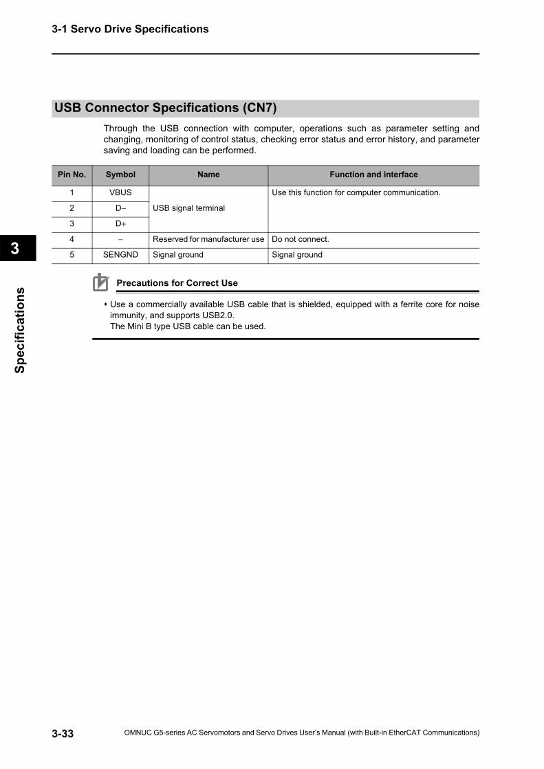
3-1 Servo Drive Specifications
3
Spec
ifica
tions
USB Connector Specifications (CN7)Through the USB connection with computer, operations such as parameter setting andchanging, monitoring of control status, checking error status and error history, and parametersaving and loading can be performed.
Precautions for Correct Use
Use a commercially available USB cable that is shielded, equipped with a ferrite core for noiseimmunity, and supports USB2.0.The Mini B type USB cable can be used.
Pin No. Symbol Name Function and interface
1 VBUS
USB signal terminal
Use this function for computer communication.
2 D−
3 D+
4 − Reserved for manufacturer use Do not connect.
5 SENGND Signal ground Signal ground
3-33 OMNUC G5-series AC Servomotors and Servo Drives User’s Manual (with Built-in EtherCAT Communications)
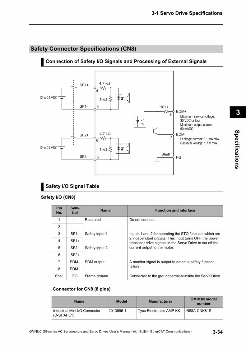
3-1 Servo Drive Specifications
3
Specifications
Safety Connector Specifications (CN8)
Connection of Safety I/O Signals and Processing of External Signals
Safety I/O Signal Table
Safety I/O (CN8)
Connector for CN8 (8 pins)
SF1+
12 to 24 VDC
SF1-
4
3
SF2+
12 to 24 VDC
SF2-
6
8EDM+
EDM-
FG
7
5
10 Ω
4.7 kΩ
1 kΩ
4.7 kΩ
1 kΩ
Maximum service voltage:30 VDC or less Maximum output current:50 mADC
Shell
Leakage current: 0.1 mA max.Residual voltage: 1.7 V max.
Pin No.
Sym-bol Name Function and interface
1 - Reserved Do not connect.
2 -
3 SF1− Safety input 1 Inputs 1 and 2 for operating the STO function, which are 2 independent circuits. This input turns OFF the power transistor drive signals in the Servo Drive to cut off the current output to the motor.
4 SF1+
5 SF2− Safety input 2
6 SF2+
7 EDM− EDM output A monitor signal is output to detect a safety function failure.
8 EDM+
Shell FG Frame ground Connected to the ground terminal inside the Servo Drive.
Name Model Manufacturer OMRON model number
Industrial Mini I/O Connector(D-SHAPE1)
2013595-1 Tyco Electronics AMP KK R88A-CNK81S
3-34OMNUC G5-series AC Servomotors and Servo Drives User’s Manual (with Built-in EtherCAT Communications)
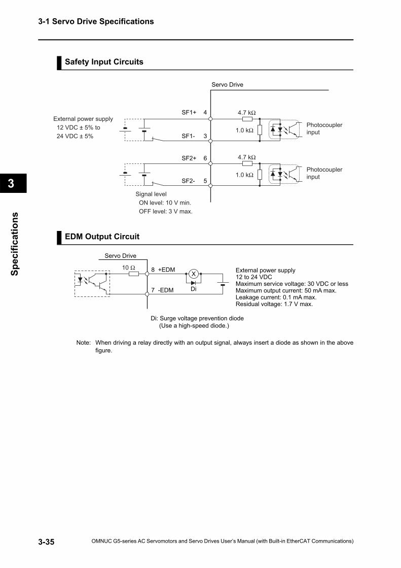
3-1 Servo Drive Specifications
3
Spec
ifica
tions
Safety Input Circuits
EDM Output Circuit
Note: When driving a relay directly with an output signal, always insert a diode as shown in the abovefigure.
Servo Drive
External power supply 12 VDC ± 5% to 24 VDC ± 5%
Signal level ON level: 10 V min. OFF level: 3 V max.
4.7 kΩ
1.0 kΩ
SF1+ 4
SF1- 3
SF2+ 6
SF2- 5
Photocoupler input
4.7 kΩ
1.0 kΩPhotocoupler input
External power supply 12 to 24 VDC Maximum service voltage: 30 VDC or less Maximum output current: 50 mA max.Leakage current: 0.1 mA max.Residual voltage: 1.7 V max.
Di: Surge voltage prevention diode (Use a high-speed diode.)
7 -EDM
8 +EDM
Di
10 Ω
Servo Drive
X
3-35 OMNUC G5-series AC Servomotors and Servo Drives User’s Manual (with Built-in EtherCAT Communications)
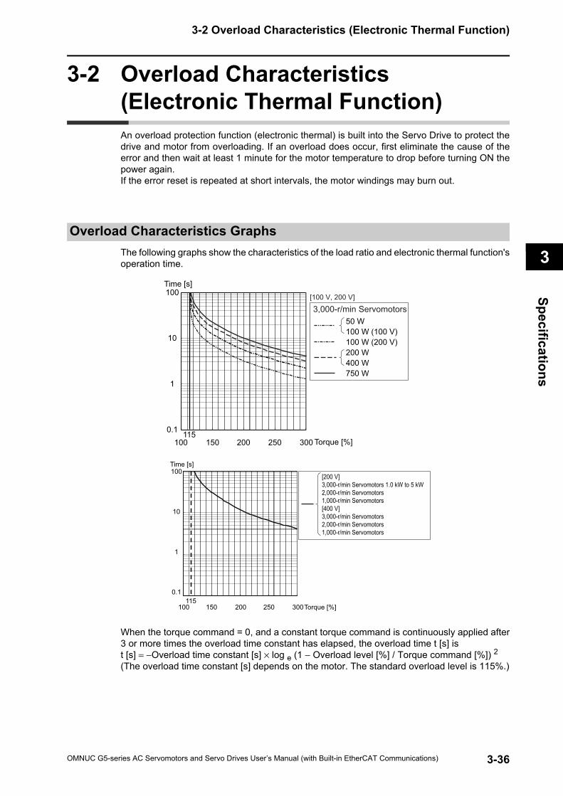
3-2 Overload Characteristics (Electronic Thermal Function)
3
Specifications
3-2 Overload Characteristics (Electronic Thermal Function)An overload protection function (electronic thermal) is built into the Servo Drive to protect thedrive and motor from overloading. If an overload does occur, first eliminate the cause of theerror and then wait at least 1 minute for the motor temperature to drop before turning ON thepower again.If the error reset is repeated at short intervals, the motor windings may burn out.
Overload Characteristics GraphsThe following graphs show the characteristics of the load ratio and electronic thermal function'soperation time.
When the torque command = 0, and a constant torque command is continuously applied after3 or more times the overload time constant has elapsed, the overload time t [s] ist [s] = −Overload time constant [s] × log e (1 − Overload level [%] / Torque command [%]) 2(The overload time constant [s] depends on the motor. The standard overload level is 115%.)
1000.1
1
10
100
150 200 250 300 Torque [%]115
Time [s]
50 W100 W (100 V)100 W (200 V)200 W400 W750 W
3,000-r/min Servomotors[100 V, 200 V]
100115
0.1
1
10
100
150 200 250 300 Torque [%]
Time [s]
[200 V]3,000-r/min Servomotors 1.0 kW to 5 kW2,000-r/min Servomotors1,000-r/min Servomotors[400 V]3,000-r/min Servomotors2,000-r/min Servomotors1,000-r/min Servomotors
3-36OMNUC G5-series AC Servomotors and Servo Drives User’s Manual (with Built-in EtherCAT Communications)
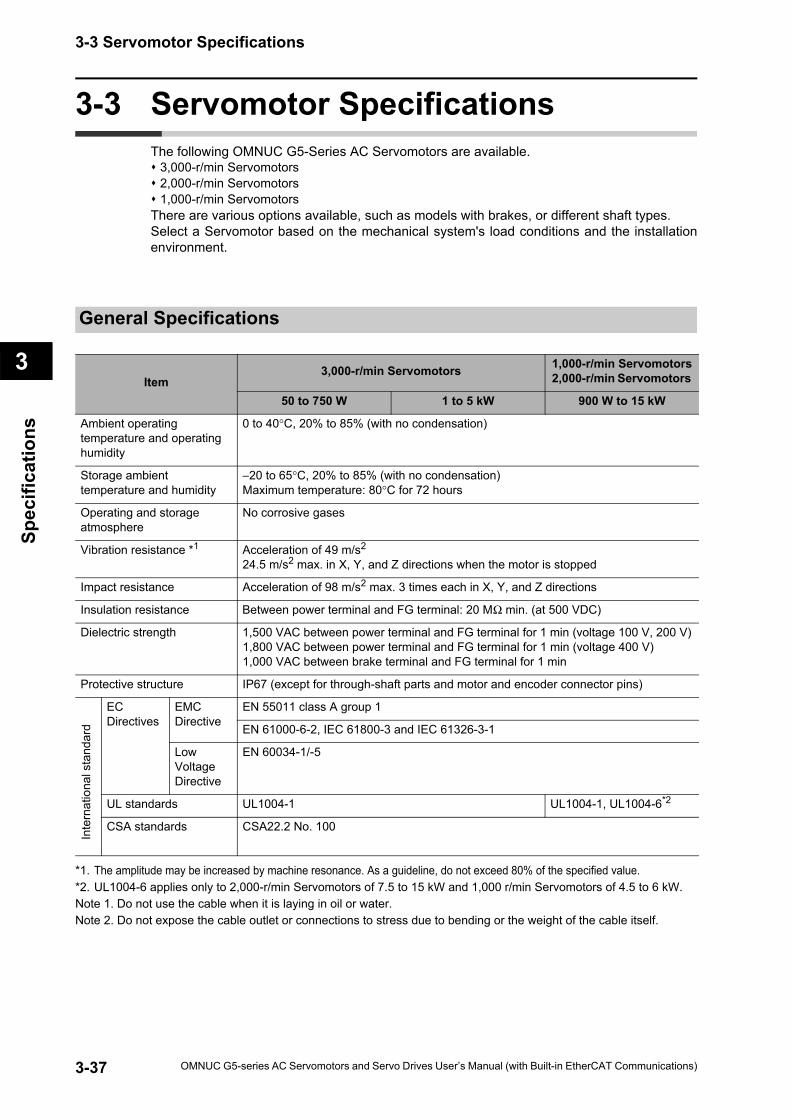
3-3 Servomotor Specifications
3
Spec
ifica
tions
3-3 Servomotor SpecificationsThe following OMNUC G5-Series AC Servomotors are available.
3,000-r/min Servomotors2,000-r/min Servomotors1,000-r/min Servomotors
There are various options available, such as models with brakes, or different shaft types.Select a Servomotor based on the mechanical system's load conditions and the installationenvironment.
General Specifications
*1. The amplitude may be increased by machine resonance. As a guideline, do not exceed 80% of the specified value.*2. UL1004-6 applies only to 2,000-r/min Servomotors of 7.5 to 15 kW and 1,000 r/min Servomotors of 4.5 to 6 kW.Note 1. Do not use the cable when it is laying in oil or water.Note 2. Do not expose the cable outlet or connections to stress due to bending or the weight of the cable itself.
Item3,000-r/min Servomotors 1,000-r/min Servomotors
2,000-r/min Servomotors
50 to 750 W 1 to 5 kW 900 W to 15 kW
Ambient operating temperature and operating humidity
0 to 40°C, 20% to 85% (with no condensation)
Storage ambient temperature and humidity
−20 to 65°C, 20% to 85% (with no condensation)Maximum temperature: 80°C for 72 hours
Operating and storage atmosphere
No corrosive gases
Vibration resistance *1 Acceleration of 49 m/s2
24.5 m/s2 max. in X, Y, and Z directions when the motor is stopped
Impact resistance Acceleration of 98 m/s2 max. 3 times each in X, Y, and Z directions
Insulation resistance Between power terminal and FG terminal: 20 MΩ min. (at 500 VDC)
Dielectric strength 1,500 VAC between power terminal and FG terminal for 1 min (voltage 100 V, 200 V)1,800 VAC between power terminal and FG terminal for 1 min (voltage 400 V)1,000 VAC between brake terminal and FG terminal for 1 min
Protective structure IP67 (except for through-shaft parts and motor and encoder connector pins)
EC Directives
EMC Directive
EN 55011 class A group 1
EN 61000-6-2, IEC 61800-3 and IEC 61326-3-1
Low VoltageDirective
EN 60034-1/-5
UL standards UL1004-1 UL1004-1, UL1004-6*2
CSA standards CSA22.2 No. 100
Inte
rnat
iona
l sta
ndar
d
3-37 OMNUC G5-series AC Servomotors and Servo Drives User’s Manual (with Built-in EtherCAT Communications)
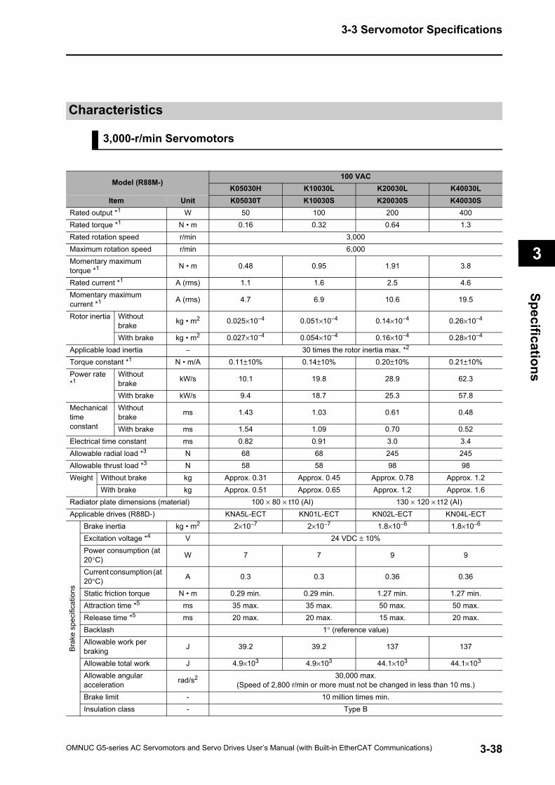
3-3 Servomotor Specifications
3
Specifications
Characteristics
3,000-r/min Servomotors
Model (R88M-)100 VAC
K05030H K10030L K20030L K40030LItem Unit K05030T K10030S K20030S K40030S
Rated output *1 W 50 100 200 400Rated torque *1 N • m 0.16 0.32 0.64 1.3Rated rotation speed r/min 3,000Maximum rotation speed r/min 6,000Momentary maximum torque *1 N • m 0.48 0.95 1.91 3.8
Rated current *1 A (rms) 1.1 1.6 2.5 4.6Momentary maximum current *1 A (rms) 4.7 6.9 10.6 19.5
Rotor inertia Without brake kg • m2 0.025×10⁻⁴ 0.051×10⁻⁴ 0.14×10⁻⁴ 0.26×10⁻⁴
With brake kg • m2 0.027×10⁻⁴ 0.054×10⁻⁴ 0.16×10⁻⁴ 0.28×10⁻⁴
Applicable load inertia − 30 times the rotor inertia max. *2
Torque constant *1 N • m/A 0.11±10% 0.14±10% 0.20±10% 0.21±10%Power rate *1
Without brake kW/s 10.1 19.8 28.9 62.3
With brake kW/s 9.4 18.7 25.3 57.8Mechanical time constant
Without brake ms 1.43 1.03 0.61 0.48
With brake ms 1.54 1.09 0.70 0.52Electrical time constant ms 0.82 0.91 3.0 3.4Allowable radial load *3 N 68 68 245 245Allowable thrust load *3 N 58 58 98 98Weight Without brake kg Approx. 0.31 Approx. 0.45 Approx. 0.78 Approx. 1.2
With brake kg Approx. 0.51 Approx. 0.65 Approx. 1.2 Approx. 1.6Radiator plate dimensions (material) 100 × 80 × t10 (AI) 130 × 120 × t12 (AI)Applicable drives (R88D-) KNA5L-ECT KN01L-ECT KN02L-ECT KN04L-ECT
Bra
ke s
peci
ficat
ions
Brake inertia kg • m2 2×10⁻⁷ 2×10⁻⁷ 1.8×10⁻⁶ 1.8×10⁻⁶
Excitation voltage *4 V 24 VDC ± 10%Power consumption (at 20°C) W 7 7 9 9
Current consumption (at 20°C) A 0.3 0.3 0.36 0.36
Static friction torque N • m 0.29 min. 0.29 min. 1.27 min. 1.27 min.Attraction time *5 ms 35 max. 35 max. 50 max. 50 max.Release time *5 ms 20 max. 20 max. 15 max. 20 max.Backlash 1° (reference value)Allowable work per braking J 39.2 39.2 137 137
Allowable total work J 4.9×10³ 4.9×10³ 44.1×10³ 44.1×10³
Allowable angular acceleration rad/s2 30,000 max.
(Speed of 2,800 r/min or more must not be changed in less than 10 ms.)Brake limit - 10 million times min.Insulation class - Type B
3-38OMNUC G5-series AC Servomotors and Servo Drives User’s Manual (with Built-in EtherCAT Communications)
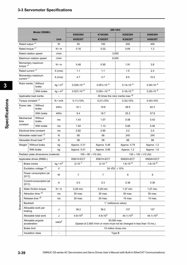
3-3 Servomotor Specifications
3
Spec
ifica
tions
Model (R88M-)200 VAC
K05030H K10030H K20030H K40030H
Item Unit K05030T K10030T K20030T K40030T
Rated output *1 W 50 100 200 400
Rated torque *1 N • m 0.16 0.32 0.64 1.3
Rated rotation speed r/min 3,000
Maximum rotation speed r/min 6,000
Momentary maximum torque *1 N • m 0.48 0.95 1.91 3.8
Rated current *1 A (rms) 1.1 1.1 1.5 2.4
Momentary maximum current *1 A (rms) 4.7 4.7 6.5 10.2
Rotor inertia Without brake kg • m2 0.025×10⁻⁴ 0.051×10⁻⁴ 0.14×10⁻⁴ 0.26×10⁻⁴
With brake kg • m2 0.027×10⁻⁴ 0.054 ×10⁻⁴ 0.16×10⁻⁴ 0.28×10⁻⁴
Applicable load inertia - 30 times the rotor inertia max.*2
Torque constant *1 N • m/A 0.11±10% 0.21±10% 0.32±10% 0.40±10%
Power rate *1
Without brake kW/s 10.1 19.8 28.9 62.3
With brake kW/s 9.4 18.7 25.3 57.8
Mechanical time constant
Without brake ms 1.43 1.07 0.58 0.43
With brake ms 1.54 1.13 0.66 0.46
Electrical time constant ms 0.82 0.90 3.2 3.4
Allowable radial load *3 N 68 68 245 245
Allowable thrust load *3 N 58 58 98 98
Weight Without brake kg Approx. 0.31 Approx. 0.46 Approx. 0.79 Approx. 1.2
With brake kg Approx. 0.51 Approx. 0.66 Approx. 1.2 Approx. 1.6
Radiator plate dimensions (material) 100 × 80 × t10 (AI) 130 × 120 × t12 (AI)
Applicable drives (R88D-) KN01H-ECT KN01H-ECT KN02H-ECT KN04H-ECT
Bra
ke s
peci
ficat
ions
Brake inertia kg • m2 2×10⁻⁷ 2×10⁻⁷ 1.8×10⁻⁶ 1.8×10⁻⁶
Excitation voltage *4 V 24 VDC ± 10%
Power consumption (at 20°C) W 7 7 9 9
Current consumption (at 20°C) A 0.3 0.3 0.36 0.36
Static friction torque N • m 0.29 min. 0.29 min. 1.27 min. 1.27 min.
Attraction time *5 ms 35 max. 35 max. 50 max. 50 max.
Release time *5 ms 20 max. 20 max. 15 max. 15 max.
Backlash 1° (reference value)
Allowable work per braking J 39.2 39.2 137 137
Allowable total work J 4.9×10³ 4.9×10³ 44.1×10³ 44.1×10³
Allowable angular acceleration rad/s2 30,000 max.
(Speed of 2,800 r/min or more must not be changed in less than 10 ms.)
Brake limit - 10 million times min.
Insulation class - Type B
3-39 OMNUC G5-series AC Servomotors and Servo Drives User’s Manual (with Built-in EtherCAT Communications)
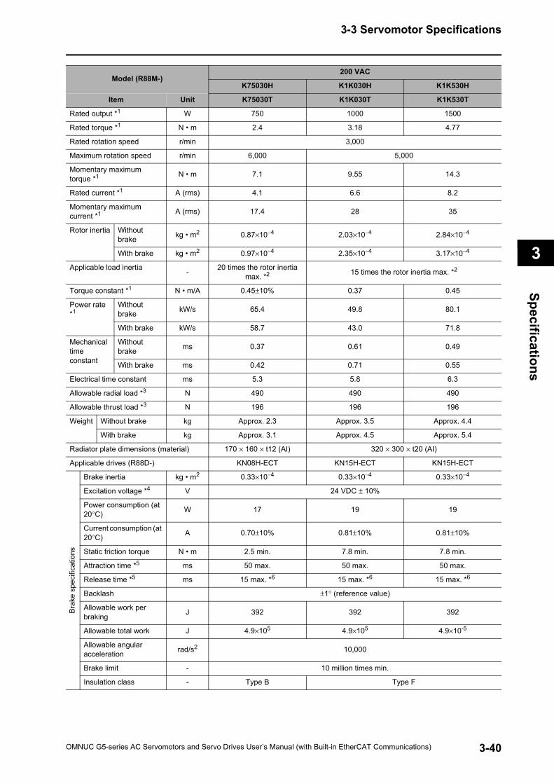
3-3 Servomotor Specifications
3
Specifications
Model (R88M-)200 VAC
K75030H K1K030H K1K530H
Item Unit K75030T K1K030T K1K530T
Rated output *1 W 750 1000 1500
Rated torque *1 N • m 2.4 3.18 4.77
Rated rotation speed r/min 3,000
Maximum rotation speed r/min 6,000 5,000
Momentary maximum torque *1 N • m 7.1 9.55 14.3
Rated current *1 A (rms) 4.1 6.6 8.2
Momentary maximum current *1 A (rms) 17.4 28 35
Rotor inertia Without brake kg • m2 0.87×10⁻⁴ 2.03×10⁻⁴ 2.84×10⁻⁴
With brake kg • m2 0.97×10⁻⁴ 2.35×10⁻⁴ 3.17×10⁻⁴
Applicable load inertia - 20 times the rotor inertia max. *2 15 times the rotor inertia max. *2
Torque constant *1 N • m/A 0.45±10% 0.37 0.45
Power rate *1
Without brake kW/s 65.4 49.8 80.1
With brake kW/s 58.7 43.0 71.8
Mechanical time constant
Without brake ms 0.37 0.61 0.49
With brake ms 0.42 0.71 0.55
Electrical time constant ms 5.3 5.8 6.3
Allowable radial load *3 N 490 490 490
Allowable thrust load *3 N 196 196 196
Weight Without brake kg Approx. 2.3 Approx. 3.5 Approx. 4.4
With brake kg Approx. 3.1 Approx. 4.5 Approx. 5.4
Radiator plate dimensions (material) 170 × 160 × t12 (AI) 320 × 300 × t20 (AI)
Applicable drives (R88D-) KN08H-ECT KN15H-ECT KN15H-ECT
Bra
ke s
peci
ficat
ions
Brake inertia kg • m2 0.33×10⁻⁴ 0.33×10⁻⁴ 0.33×10⁻⁴
Excitation voltage *4 V 24 VDC ± 10%
Power consumption (at 20°C) W 17 19 19
Current consumption (at 20°C) A 0.70±10% 0.81±10% 0.81±10%
Static friction torque N • m 2.5 min. 7.8 min. 7.8 min.
Attraction time *5 ms 50 max. 50 max. 50 max.
Release time *5 ms 15 max. *6 15 max. *6 15 max. *6
Backlash ±1° (reference value)
Allowable work per braking J 392 392 392
Allowable total work J 4.9×10⁵ 4.9×10⁵ 4.9×10⁻⁵
Allowable angular acceleration rad/s2 10,000
Brake limit - 10 million times min.
Insulation class - Type B Type F
3-40OMNUC G5-series AC Servomotors and Servo Drives User’s Manual (with Built-in EtherCAT Communications)

3-3 Servomotor Specifications
3
Spec
ifica
tions
Model (R88M-)200 VAC
K2K030H K3K030H K4K030H K5K030H
Item Unit K2K030T K3K030T K4K030T K5K030T
Rated output *1 W 2000 3000 4000 5000
Rated torque *1 N • m 6.37 9.55 12.7 15.9
Rated rotation speed r/min 3,000
Maximum rotation speed r/min 5,000 4,500 4,500
Momentary maximum torque *1 N • m 19.1 28.6 38.2 47.7
Rated current *1 A (rms) 11.3 18.1 19.6 24.0
Momentary maximum current *1 A (rms) 48 77 83 102
Rotor inertia Without brake kg • m2 3.68×10⁻⁴ 6.50×10⁻⁴ 12.9×10⁻⁴ 17.4×10⁻⁴
With brake kg • m2 4.01×10⁻⁴ 7.85×10⁻⁴ 14.2×10⁻⁴ 18.6×10⁻⁴
Applicable load inertia - 15 times the rotor inertia max. *2
Torque constant *1 N • m/A 0.44 0.41 0.49 0.49
Power rate *1
Without brake kW/s 110 140 126 146
With brake kW/s 101 116 114 136
Mechanical time constant
Without brake ms 0.44 0.41 0.51 0.50
With brake ms 0.48 0.49 0.56 0.54
Electrical time constant ms 6.7 11 12 13
Allowable radial load *3 N 490 490 784 784
Allowable thrust load *3 N 196 196 343 343
Weight Without brake kg Approx. 5.3 Approx. 8.3 Approx. 11.0 Approx. 14.0
With brake kg Approx. 6.3 Approx. 9.4 Approx. 12.6 Approx. 16.0
Radiator plate dimensions (material) 380 × 350 × t30 (AI)
Applicable drives (R88D-) KN20H-ECT KN30H-ECT KN50H-ECT KN50H-ECT
Bra
ke s
peci
ficat
ions
Brake inertia kg • m2 0.33×10⁻⁴ 0.33×10⁻⁴ 1.35×10⁻⁴ 1.35×10⁻⁴
Excitation voltage *4 V 24 VDC ± 10%
Power consumption (at 20°C) W 19 19 22 22
Current consumption (at 20°C) A 0.81±10% 0.81±10% 0.90±10% 0.90±10%
Static friction torque N • m 7.8 min. 11.8 min. 16.1 min. 16.1 min.
Attraction time *5 ms 50 max. 80 max. 110 max. 110 max.
Release time *5 ms 15 max. *6 15 max. *6 50 max. *7 50 max. *7
Backlash ±1° (reference value)
Allowable work per braking J 392 392 1470 1470
Allowable total work J 4.9×10⁶ 4.9×10⁶ 2.2×10⁶ 2.2×10⁶
Allowable angular acceleration rad/s2 10,000
Brake limit - 10 million times min.
Rating - Continuous
Insulation class - Type F
3-41 OMNUC G5-series AC Servomotors and Servo Drives User’s Manual (with Built-in EtherCAT Communications)
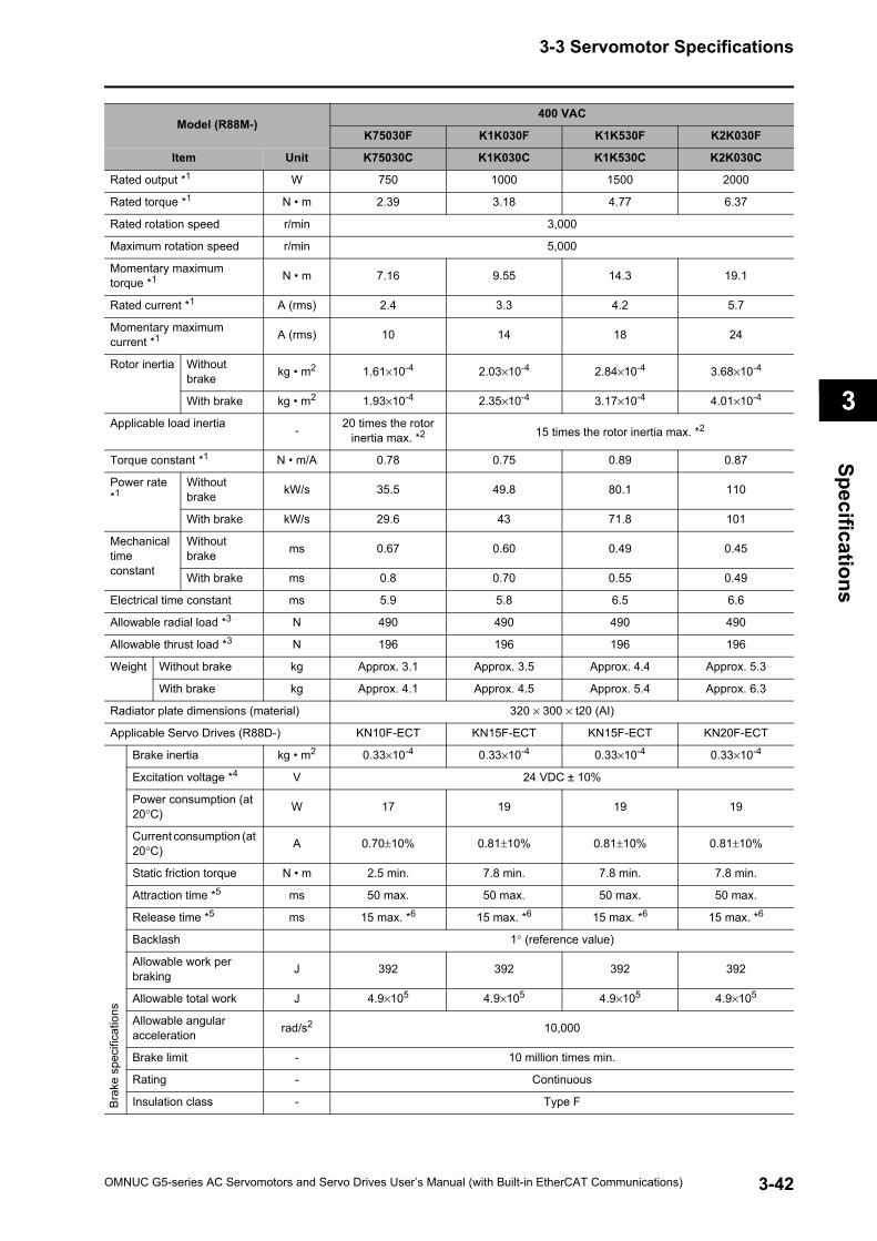
3-3 Servomotor Specifications
3
Specifications
Model (R88M-)400 VAC
K75030F K1K030F K1K530F K2K030F
Item Unit K75030C K1K030C K1K530C K2K030C
Rated output *1 W 750 1000 1500 2000
Rated torque *1 N • m 2.39 3.18 4.77 6.37
Rated rotation speed r/min 3,000
Maximum rotation speed r/min 5,000
Momentary maximum torque *1 N • m 7.16 9.55 14.3 19.1
Rated current *1 A (rms) 2.4 3.3 4.2 5.7
Momentary maximum current *1 A (rms) 10 14 18 24
Rotor inertia Without brake kg • m2 1.61×10⁻⁴ 2.03×10⁻⁴ 2.84×10⁻⁴ 3.68×10⁻⁴
With brake kg • m2 1.93×10⁻⁴ 2.35×10⁻⁴ 3.17×10⁻⁴ 4.01×10⁻⁴
Applicable load inertia - 20 times the rotor inertia max. *2 15 times the rotor inertia max. *2
Torque constant *1 N • m/A 0.78 0.75 0.89 0.87
Power rate *1
Without brake kW/s 35.5 49.8 80.1 110
With brake kW/s 29.6 43 71.8 101
Mechanical time constant
Without brake ms 0.67 0.60 0.49 0.45
With brake ms 0.8 0.70 0.55 0.49
Electrical time constant ms 5.9 5.8 6.5 6.6
Allowable radial load *3 N 490 490 490 490
Allowable thrust load *3 N 196 196 196 196
Weight Without brake kg Approx. 3.1 Approx. 3.5 Approx. 4.4 Approx. 5.3
With brake kg Approx. 4.1 Approx. 4.5 Approx. 5.4 Approx. 6.3
Radiator plate dimensions (material) 320 × 300 × t20 (AI)
Applicable Servo Drives (R88D-) KN10F-ECT KN15F-ECT KN15F-ECT KN20F-ECT
Bra
ke s
peci
ficat
ions
Brake inertia kg • m2 0.33×10⁻⁴ 0.33×10⁻⁴ 0.33×10⁻⁴ 0.33×10⁻⁴
Excitation voltage *4 V 24 VDC ± 10%
Power consumption (at 20°C) W 17 19 19 19
Current consumption (at 20°C) A 0.70±10% 0.81±10% 0.81±10% 0.81±10%
Static friction torque N • m 2.5 min. 7.8 min. 7.8 min. 7.8 min.
Attraction time *5 ms 50 max. 50 max. 50 max. 50 max.
Release time *5 ms 15 max. *6 15 max. *6 15 max. *6 15 max. *6
Backlash 1° (reference value)
Allowable work per braking J 392 392 392 392
Allowable total work J 4.9×10⁵ 4.9×10⁵ 4.9×10⁵ 4.9×10⁵
Allowable angular acceleration rad/s2 10,000
Brake limit - 10 million times min.
Rating - Continuous
Insulation class - Type F
3-42OMNUC G5-series AC Servomotors and Servo Drives User’s Manual (with Built-in EtherCAT Communications)
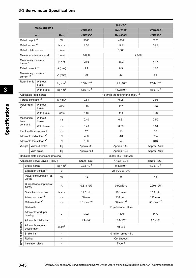
3-3 Servomotor Specifications
3
Spec
ifica
tions
Model (R88M-)400 VAC
K3K030F K4K030F K5K030F
Item Unit K3K030C K4K030C K5K030C
Rated output *1 W 3000 4000 5000
Rated torque *1 N • m 9.55 12.7 15.9
Rated rotation speed r/min 3,000
Maximum rotation speed r/min 5,000 4,500
Momentary maximum torque *1 N • m 28.6 38.2 47.7
Rated current *1 A (rms) 9.2 9.9 12.0
Momentary maximum current *1 A (rms) 39 42 51
Rotor inertia Without brake kg • m2 6.50×10⁻⁴ 12.9×10⁻⁴ 17.4×10⁻⁴
With brake kg • m2 7.85×10⁻⁴ 14.2×10⁻⁴ 18.6×10⁻⁴
Applicable load inertia - 15 times the rotor inertia max. *2
Torque constant *1 N • m/A 0.81 0.98 0.98
Power rate *1
Without brake kW/s 140 126 146
With brake kW/s 116 114 136
Mechanical time constant
Without brake ms 0.40 0.51 0.50
With brake ms 0.49 0.56 0.54
Electrical time constant ms 12 13 13
Allowable radial load *3 N 490 784 784
Allowable thrust load *3 N 196 343 343
Weight Without brake kg Approx. 8.3 Approx. 11.0 Approx. 14.0
With brake kg Approx. 9.4 Approx. 12.6 Approx. 16.0
Radiator plate dimensions (material) 380 × 350 × t30 (AI)
Applicable Servo Drives (R88D-) KN30F-ECT KN50F-ECT KN50F-ECT
Bra
ke s
peci
ficat
ions
Brake inertia kg • m2 0.33×10⁻⁴ 0.33×10⁻⁴ 1.35×10⁻⁴
Excitation voltage *4 V 24 VDC ± 10%
Power consumption (at 20°C) W 19 22 22
Current consumption (at 20°C) A 0.81±10% 0.90±10% 0.90±10%
Static friction torque N • m 11.8 min. 16.1 min. 16.1 min.
Attraction time *5 ms 80 max. 110 max. 110 max.
Release time *5 ms 15 max. *6 50 max. *7 50 max. *7
Backlash 1° (reference value)
Allowable work per braking J 392 1470 1470
Allowable total work J 4.9×10⁵ 2.2×10⁶ 2.2×10⁶
Allowable angular acceleration rad/s2 10,000
Brake limit - 10 million times min.
Rating - Continuous
Insulation class - Type F
3-43 OMNUC G5-series AC Servomotors and Servo Drives User’s Manual (with Built-in EtherCAT Communications)
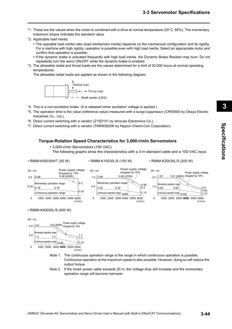
3-3 Servomotor Specifications
3
Specifications
*1. These are the values when the motor is combined with a drive at normal temperature (20°C, 65%). The momentary maximum torque indicates the standard value.
*2. Applicable load inertia. The operable load inertia ratio (load inertia/rotor inertia) depends on the mechanical configuration and its rigidity.For a machine with high rigidity, operation is possible even with high load inertia. Select an appropriate motor andconfirm that operation is possible.
If the dynamic brake is activated frequently with high load inertia, the Dynamic Brake Resistor may burn. Do notrepeatedly turn the servo ON/OFF while the dynamic brake is enabled.
*3. The allowable radial and thrust loads are the values determined for a limit of 20,000 hours at normal operating temperatures.The allowable radial loads are applied as shown in the following diagram.
*4. This is a non-excitation brake. (It is released when excitation voltage is applied.)*5. The operation time is the value (reference value) measured with a surge suppressor (CR50500 by Okaya Electric
Industries Co., Ltd.). *6. Direct current switching with a varistor (Z15D151 by Ishizuka Electronics Co.). *7. Direct current switching with a varistor (TNR9G820K by Nippon Chemi-Con Corporation).
Torque-Rotation Speed Characteristics for 3,000-r/min Servomotors3,000-r/min Servomotors (100 VAC) The following graphs show the characteristics with a 3-m standard cable and a 100-VAC input.
• R88M-K05030H/T (50 W) • R88M-K10030L/S (100 W) • R88M-K20030L/S (200 W)
• R88M-K40030L/S (400 W)
Note 1. The continuous operation range is the range in which continuous operation is possible. Continuous operation at the maximum speed is also possible. However, doing so will reduce the output torque.
Note 2. If the motor power cable exceeds 20 m, the voltage drop will increase and the momentary operation range will become narrower.
Radial load
Thrust load
Shaft center (LR/2)
0.25
0 1000 2000 3000 4000 6000 (r/min)
5000
0.5 0.48
0.16 0.16
0.48 (4000)
0.3
(N • m)
Momentary operation range
Continuous operation range
Power supply voltage dropped by 10%
0.08
0.5
0 1000 2000 3000 40004300
6000 (r/min)
5000
1.0 0.95 0.95 (3700)
0.560.40.32 0.32
(N • m)
Momentary operation range
Continuous operation range
Power supply voltage dropped by 10%
0.16
1.0
0 1000 2000 3000 40004000 6000 (r/min)
5000
2.0 1.91
0.80.64
1.91 (2600)
0.64 0.64
(N • m)
Momentary operation range
Continuous operation range
Power supply voltage dropped by 10%
0.32 3100
2.0
0 1000 2000 3000 40004000 6000 (r/min)
5000
4.0 3.8 3.8 (2600)
1.71.31.3 1.3
(N • m)
Momentary operation range
Continuous operation range
Power supply voltage dropped by 10%
0.323100
3-44OMNUC G5-series AC Servomotors and Servo Drives User’s Manual (with Built-in EtherCAT Communications)
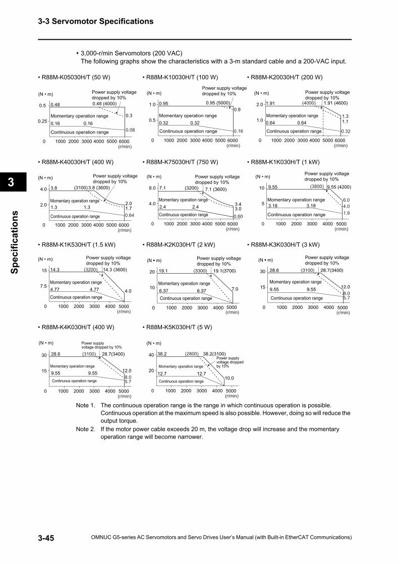
3-3 Servomotor Specifications
3
Spec
ifica
tions
3,000-r/min Servomotors (200 VAC) The following graphs show the characteristics with a 3-m standard cable and a 200-VAC input.
• R88M-K05030H/T (50 W) • R88M-K10030H/T (100 W) • R88M-K20030H/T (200 W)
• R88M-K40030H/T (400 W) • R88M-K75030H/T (750 W) • R88M-K1K030H/T (1 kW)
• R88M-K1K530H/T (1.5 kW) • R88M-K2K030H/T (2 kW) • R88M-K3K030H/T (3 kW)
• R88M-K4K030H/T (400 W) • R88M-K5K030H/T (5 W)
Note 1. The continuous operation range is the range in which continuous operation is possible. Continuous operation at the maximum speed is also possible. However, doing so will reduce the output torque.
Note 2. If the motor power cable exceeds 20 m, the voltage drop will increase and the momentary operation range will become narrower.
0.5
0 1000 2000 3000 4000 6000 (r/min)
5000
1.0 0.95
0.32 0.32
0.95 (5000)0.9
(N • m)
Momentary operation range
Continuous operation range
Power supply voltage dropped by 10%
0.16
1.0
0 1000 2000 3000 4000 6000 (r/min)
5000
2.0 1.91
0.64 0.64
1.91 (4600)
1.3 1.1
(N • m)
Momentary operation range
Continuous operation range
Power supply voltage dropped by 10%
0.32
(4000)
0.25
0 1000 2000 3000 4000 6000 (r/min)
5000
0.5 0.48
0.16 0.16
0.48 (4000)
0.3
(N • m)
Momentary operation range
Continuous operation range
Power supply voltage dropped by 10%
0.08
2.0
0 1000 2000 3000 4000 6000 (r/min)
5000
4.0 3.8
1.3 1.3 1.72.0
3.8 (3600)
(N • m)
Momentary operation range
Continuous operation range
Power supply voltage dropped by 10%
0.64
(3100)
4.0
0 1000 2000 3000
(3200)
4000 6000(r/min)
5000
8.0 7.1
3.43.0
7.1 (3600)
2.4 2.4
(N • m)
Momentary operation range
Continuous operation range
Power supply voltage dropped by 10%
0.60
5
0 1000 2000 3000 4000 5000(r/min)
10 9.55 9.55 (4200)
3.18 3.18
(N • m)
Momentary operation range
Continuous operation range
Power supply voltage dropped by 10%
6.04.01.9
(3800)
7.5
0 1000 2000 3000 4000 5000(r/min)
15 14.3 14.3 (3600)
4.77 4.77
(N • m)
Momentary operation range
Continuous operation range
Power supply voltage dropped by 10%
4.0
(3200)
10
0 1000 2000 3000 4000
20 19.1 19.1(3700)
6.37 6.37 7.0
(3300)
Power supply voltage dropped by 10%
(N • m)
Momentary operation range
Continuous operation range
5000 (r/min)
15
0 1000 2000 3000 4000
30 28.6 28.7(3400)
9.55 9.55 12.0
5.78.0
(3100)
Power supply voltage dropped by 10%
(N • m)
Momentary operation range
Continuous operation range
5000 (r/min)
15
0 1000 2000 3000 4000 5000 (r/min)
30 28.6 28.7(3400)
9.55 9.55 12.0
5.78.0
(3100)
Power supply voltage dropped by 10%
Momentary operation range
(N • m)
Continuous operation range
20
0 1000 2000 3000 4000 5000 (r/min)
40 38.2
12.7 12.7
38.2(3100)
10.0
(2800)Power supply voltage dropped by 10%
(N • m)
Momentary operation range
Continuous operation range
3-45 OMNUC G5-series AC Servomotors and Servo Drives User’s Manual (with Built-in EtherCAT Communications)
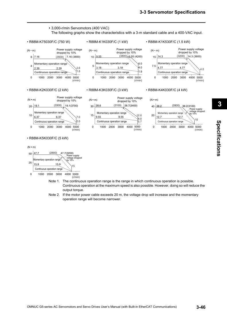
3-3 Servomotor Specifications
3
Specifications
3,000-r/min Servomotors (400 VAC) The following graphs show the characteristics with a 3-m standard cable and a 400-VAC input.
• R88M-K75030F/C (750 W) • R88M-K1K030F/C (1 kW) • R88M-K1K530F/C (1.5 kW)
• R88M-K2K030F/C (2 kW) • R88M-K3K030F/C (3 kW) • R88M-K4K030F/C (4 kW)
• R88M-K5K030F/C (5 kW)
Note 1. The continuous operation range is the range in which continuous operation is possible. Continuous operation at the maximum speed is also possible. However, doing so will reduce the output torque.
Note 2. If the motor power cable exceeds 20 m, the voltage drop will increase and the momentary operation range will become narrower.
4
0 1000 2000 3000 4000 5000 (r/min)
8 7.16 7.16 (3800)
2.39 2.39
(N • m)
Momentary operation range
Continuous operation range
Power supply voltage dropped by 10%
2.61.6
(3500)
5
0 1000 2000 3000 4000 5000 (r/min)
10 9.55 9.55 (4200)
3.18 3.18
(N • m)
Momentary operation range
Continuous operation range
Power supply voltage dropped by 10%
1.9
6.04.0
(3800)
7.5
0 1000 2000 3000 4000 5000 (r/min)
15 14.3 14.3 (3600)
4.77 4.77
(N • m)
Momentary operation range
Continuous operation range
Power supply voltage dropped by 10%
4.0
(3200)
10
0 1000 2000 3000 4000
20 19.1
6.37 6.37
19.1(3700)
7.0
2.0
(3300)
Power supply voltage dropped by 10%(N • m)
Momentary operation range
Continuous operation range
5000(r/min)
15
0 1000 2000 3000 4000
30 28.6 28.7(3400)
9.55 9.55
5.7
12.08.0
(3100)
Power supply voltage dropped by 10%
Momentary operation range
(N • m)
Continuous operation range
5000 (r/min)
20
0 1000 2000 3000 4000
40 38.2
12.7 12.7
38.2(3100)
10
(2800)Power supply voltage dropped by 10%Momentary operation range
(N • m)
Continuous operation range
5000 (r/min)
25
0 1000 2000 3000 4000
50 47.7 47.7(3200)
15.9 15.9 15
(2800)Power supply voltage dropped by 10%
(N • m)
Momentary operation range
Continuous operation range
5000 (r/min)
3-46OMNUC G5-series AC Servomotors and Servo Drives User’s Manual (with Built-in EtherCAT Communications)
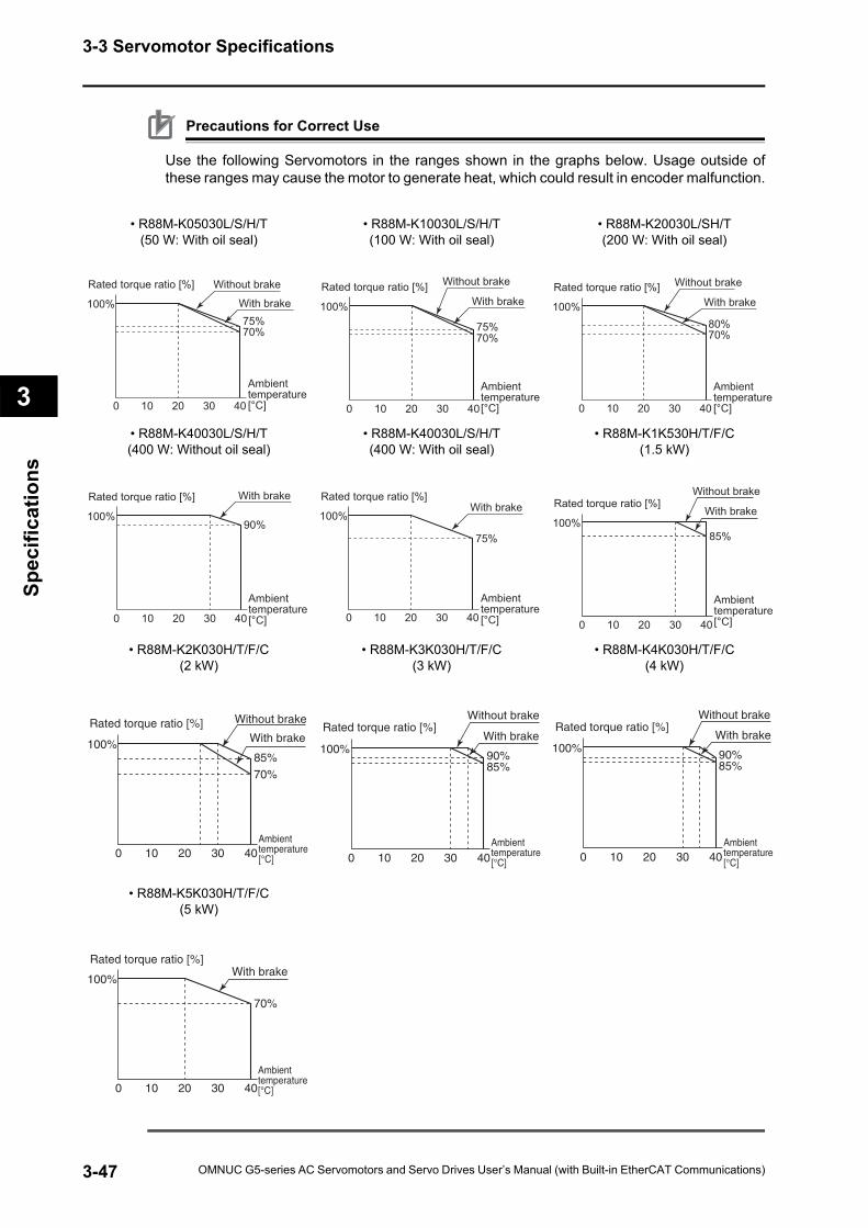
3-3 Servomotor Specifications
3
Spec
ifica
tions
Precautions for Correct Use
Use the following Servomotors in the ranges shown in the graphs below. Usage outside ofthese ranges may cause the motor to generate heat, which could result in encoder malfunction.
• R88M-K05030L/S/H/T(50 W: With oil seal)
• R88M-K10030L/S/H/T (100 W: With oil seal)
• R88M-K20030L/SH/T(200 W: With oil seal)
• R88M-K40030L/S/H/T(400 W: Without oil seal)
• R88M-K40030L/S/H/T(400 W: With oil seal)
• R88M-K1K530H/T/F/C(1.5 kW)
• R88M-K2K030H/T/F/C(2 kW)
• R88M-K3K030H/T/F/C(3 kW)
• R88M-K4K030H/T/F/C(4 kW)
• R88M-K5K030H/T/F/C(5 kW)
Rated torque ratio [%]
Ambient temperature [°C]
100%75%70%
100 20 30 40
Without brake
With brakeRated torque ratio [%]
100%
75%70%
100 20 30 40
Without brake
With brake
Ambient temperature [°C]
Rated torque ratio [%]
100%80%70%
100 20 30 40
Without brake
With brake
Ambient temperature [°C]
Rated torque ratio [%]
100%90%
100 20 30 40
With brake
Ambient temperature [°C]
Rated torque ratio [%]
100%
75%
100 20 30 40
With brake
Ambient temperature [°C]
Rated torque ratio [%]
100%85%
100 20 30 40
Without brake
With brake
Ambient temperature [°C]
100%85%70%
100 20 30 40
Without brake
With brake
Ambient temperature [°C]
Rated torque ratio [%]
100%
85%90%
100 20 30 40
Without brake
With brake
Ambient temperature [°C]
Rated torque ratio [%]
100%
85%90%
100 20 30 40
Without brake
With brake
Ambient temperature [°C]
Rated torque ratio [%]
100%
70%
100 20 30 40
With brakeRated torque ratio [%]
Ambient temperature [°C]
3-47 OMNUC G5-series AC Servomotors and Servo Drives User’s Manual (with Built-in EtherCAT Communications)
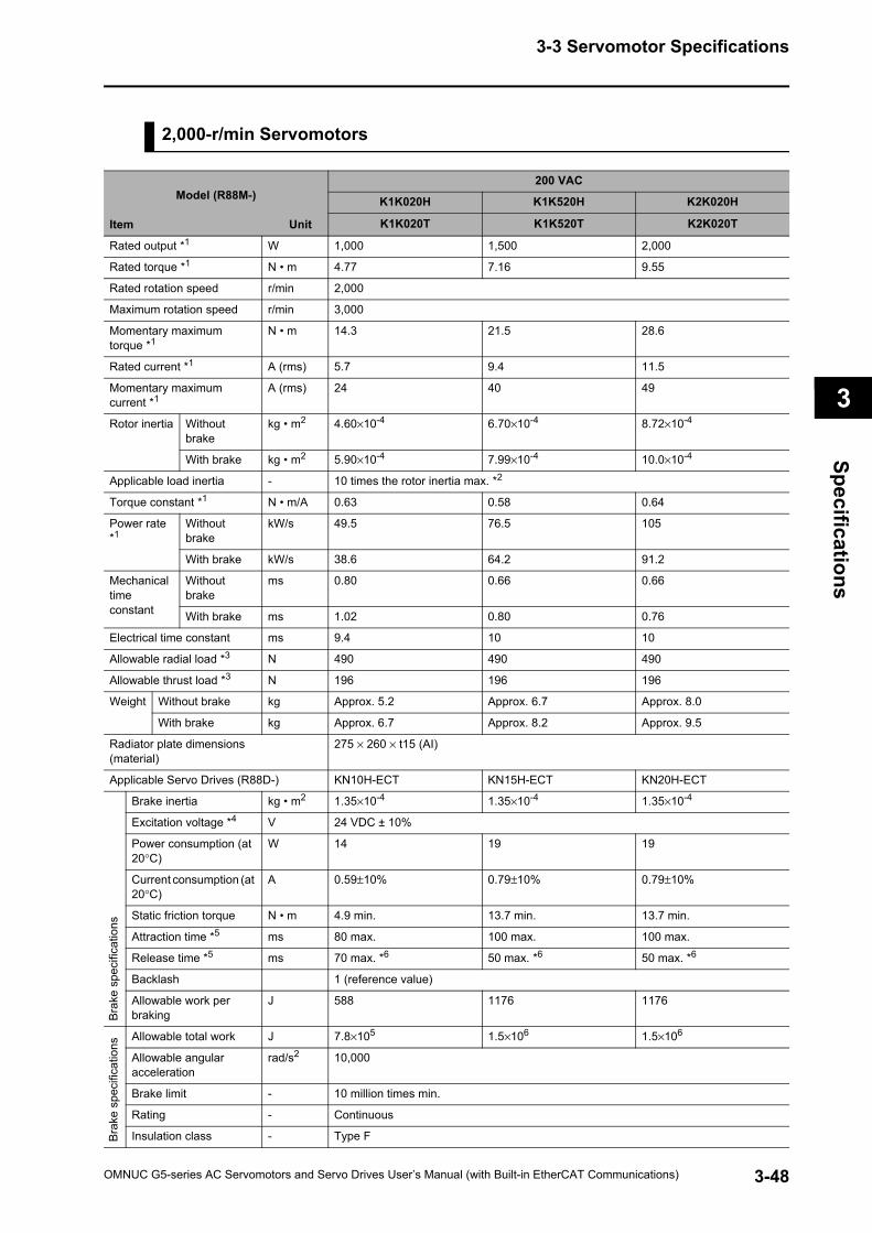
3-3 Servomotor Specifications
3
Specifications
2,000-r/min Servomotors
Model (R88M-)
Item Unit
200 VAC
K1K020H K1K520H K2K020H
K1K020T K1K520T K2K020T
Rated output *1 W 1,000 1,500 2,000
Rated torque *1 N • m 4.77 7.16 9.55
Rated rotation speed r/min 2,000
Maximum rotation speed r/min 3,000
Momentary maximum torque *1
N • m 14.3 21.5 28.6
Rated current *1 A (rms) 5.7 9.4 11.5
Momentary maximum current *1
A (rms) 24 40 49
Rotor inertia Without brake
kg • m2 4.60×10⁻⁴ 6.70×10⁻⁴ 8.72×10⁻⁴
With brake kg • m2 5.90×10⁻⁴ 7.99×10⁻⁴ 10.0×10⁻⁴
Applicable load inertia - 10 times the rotor inertia max. *2
Torque constant *1 N • m/A 0.63 0.58 0.64
Power rate *1
Without brake
kW/s 49.5 76.5 105
With brake kW/s 38.6 64.2 91.2
Mechanical time constant
Without brake
ms 0.80 0.66 0.66
With brake ms 1.02 0.80 0.76
Electrical time constant ms 9.4 10 10
Allowable radial load *3 N 490 490 490
Allowable thrust load *3 N 196 196 196
Weight Without brake kg Approx. 5.2 Approx. 6.7 Approx. 8.0
With brake kg Approx. 6.7 Approx. 8.2 Approx. 9.5
Radiator plate dimensions(material)
275 × 260 × t15 (AI)
Applicable Servo Drives (R88D-) KN10H-ECT KN15H-ECT KN20H-ECT
Bra
ke s
peci
ficat
ions
Brake inertia kg • m2 1.35×10⁻⁴ 1.35×10⁻⁴ 1.35×10⁻⁴
Excitation voltage *4 V 24 VDC ± 10%
Power consumption (at 20°C)
W 14 19 19
Current consumption (at 20°C)
A 0.59±10% 0.79±10% 0.79±10%
Static friction torque N • m 4.9 min. 13.7 min. 13.7 min.
Attraction time *5 ms 80 max. 100 max. 100 max.
Release time *5 ms 70 max. *6 50 max. *6 50 max. *6
Backlash 1 (reference value)
Allowable work per braking
J 588 1176 1176
Bra
ke s
peci
ficat
ions
Allowable total work J 7.8×10⁵ 1.5×10⁶ 1.5×10⁶
Allowable angular acceleration
rad/s2 10,000
Brake limit - 10 million times min.
Rating - Continuous
Insulation class - Type F
3-48OMNUC G5-series AC Servomotors and Servo Drives User’s Manual (with Built-in EtherCAT Communications)
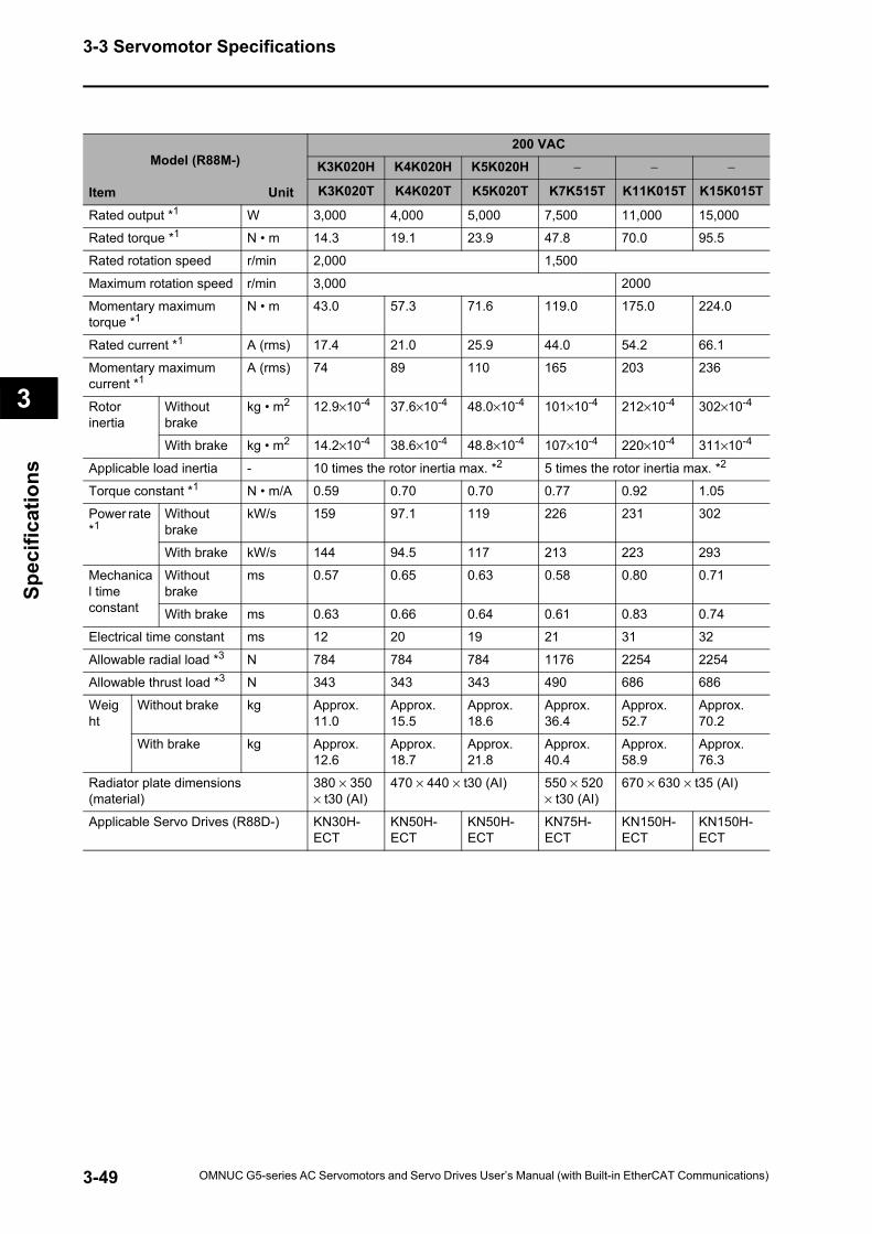
3-3 Servomotor Specifications
3
Spec
ifica
tions
Model (R88M-)
Item Unit
200 VACK3K020H K4K020H K5K020H − − −
K3K020T K4K020T K5K020T K7K515T K11K015T K15K015T
Rated output *1 W 3,000 4,000 5,000 7,500 11,000 15,000
Rated torque *1 N • m 14.3 19.1 23.9 47.8 70.0 95.5
Rated rotation speed r/min 2,000 1,500
Maximum rotation speed r/min 3,000 2000
Momentary maximum torque *1
N • m 43.0 57.3 71.6 119.0 175.0 224.0
Rated current *1 A (rms) 17.4 21.0 25.9 44.0 54.2 66.1
Momentary maximum current *1
A (rms) 74 89 110 165 203 236
Rotor inertia
Without brake
kg • m2 12.9×10⁻⁴ 37.6×10⁻⁴ 48.0×10⁻⁴ 101×10-4 212×10-4 302×10-4
With brake kg • m2 14.2×10⁻⁴ 38.6×10⁻⁴ 48.8×10⁻⁴ 107×10-4 220×10-4 311×10-4
Applicable load inertia - 10 times the rotor inertia max. *2 5 times the rotor inertia max. *2
Torque constant *1 N • m/A 0.59 0.70 0.70 0.77 0.92 1.05
Power rate *1
Without brake
kW/s 159 97.1 119 226 231 302
With brake kW/s 144 94.5 117 213 223 293
Mechanical time constant
Without brake
ms 0.57 0.65 0.63 0.58 0.80 0.71
With brake ms 0.63 0.66 0.64 0.61 0.83 0.74
Electrical time constant ms 12 20 19 21 31 32
Allowable radial load *3 N 784 784 784 1176 2254 2254
Allowable thrust load *3 N 343 343 343 490 686 686
Weight
Without brake kg Approx. 11.0
Approx. 15.5
Approx. 18.6
Approx. 36.4
Approx. 52.7
Approx. 70.2
With brake kg Approx. 12.6
Approx. 18.7
Approx. 21.8
Approx. 40.4
Approx. 58.9
Approx. 76.3
Radiator plate dimensions (material)
380 × 350 × t30 (AI)
470 × 440 × t30 (AI) 550 × 520 × t30 (AI)
670 × 630 × t35 (AI)
Applicable Servo Drives (R88D-) KN30H-ECT
KN50H-ECT
KN50H-ECT
KN75H-ECT
KN150H-ECT
KN150H-ECT
3-49 OMNUC G5-series AC Servomotors and Servo Drives User’s Manual (with Built-in EtherCAT Communications)
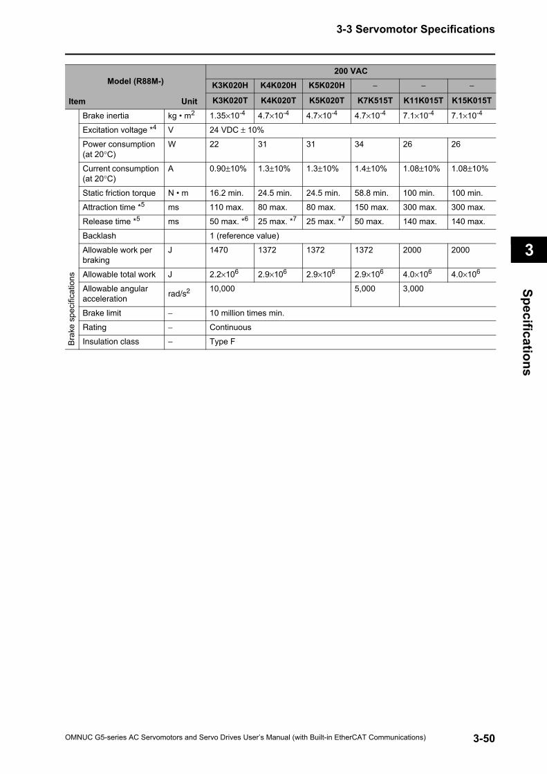
3-3 Servomotor Specifications
3
Specifications
Bra
ke s
peci
ficat
ions
Brake inertia kg • m2 1.35×10⁻⁴ 4.7×10⁻⁴ 4.7×10⁻⁴ 4.7×10⁻⁴ 7.1×10⁻⁴ 7.1×10⁻⁴
Excitation voltage *4 V 24 VDC ± 10%
Power consumption (at 20°C)
W 22 31 31 34 26 26
Current consumption (at 20°C)
A 0.90±10% 1.3±10% 1.3±10% 1.4±10% 1.08±10% 1.08±10%
Static friction torque N • m 16.2 min. 24.5 min. 24.5 min. 58.8 min. 100 min. 100 min.
Attraction time *5 ms 110 max. 80 max. 80 max. 150 max. 300 max. 300 max.
Release time *5 ms 50 max. *6 25 max. *7 25 max. *7 50 max. 140 max. 140 max.
Backlash 1 (reference value)
Allowable work per braking
J 1470 1372 1372 1372 2000 2000
Allowable total work J 2.2×10⁶ 2.9×10⁶ 2.9×10⁶ 2.9×10⁶ 4.0×10⁶ 4.0×10⁶
Allowable angular acceleration
rad/s2 10,000 5,000 3,000
Brake limit − 10 million times min.
Rating − Continuous
Insulation class − Type F
Model (R88M-)
Item Unit
200 VACK3K020H K4K020H K5K020H − − −
K3K020T K4K020T K5K020T K7K515T K11K015T K15K015T
3-50OMNUC G5-series AC Servomotors and Servo Drives User’s Manual (with Built-in EtherCAT Communications)
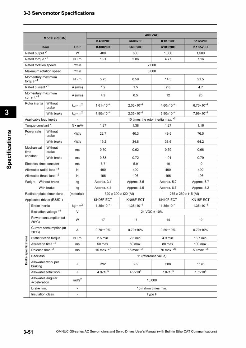
3-3 Servomotor Specifications
3
Spec
ifica
tions
Model (R88M-)400 VAC
K40020F K60020F K1K020F K1K520F
Item Unit K40020C K60020C K1K020C K1K520C
Rated output *1 W 400 600 1,000 1,500
Rated torque *1 N • m 1.91 2.86 4.77 7.16
Rated rotation speed r/min 2,000
Maximum rotation speed r/min 3,000
Momentary maximum torque *1 N • m 5.73 8.59 14.3 21.5
Rated current *1 A (rms) 1.2 1.5 2.8 4.7
Momentary maximum current *1 A (rms) 4.9 6.5 12 20
Rotor inertia Without brake kg • m2 1.61×10⁻⁴ 2.03×10⁻⁴ 4.60×10⁻⁴ 6.70×10⁻⁴
With brake kg • m2 1.90×10⁻⁴ 2.35×10⁻⁴ 5.90×10⁻⁴ 7.99×10⁻⁴
Applicable load inertia - 10 times the rotor inertia max. *2
Torque constant *1 N • m/A 1.27 1.38 1.27 1.16
Power rate *1
Without brake kW/s 22.7 40.3 49.5 76.5
With brake kW/s 19.2 34.8 38.6 64.2
Mechanical time constant
Without brake ms 0.70 0.62 0.79 0.66
With brake ms 0.83 0.72 1.01 0.79
Electrical time constant ms 5.7 5.9 10 10
Allowable radial load *3 N 490 490 490 490
Allowable thrust load *3 N 196 196 196 196
Weight Without brake kg Approx. 3.1 Approx. 3.5 Approx. 5.2 Approx. 6.7
With brake kg Approx. 4.1 Approx. 4.5 Approx. 6.7 Approx. 8.2
Radiator plate dimensions (material) 320 × 300 × t20 (AI) 275 × 260 × t15 (AI)
Applicable drives (R88D-) KN06F-ECT KN06F-ECT KN10F-ECT KN15F-ECT
Bra
ke s
peci
ficat
ions
Brake inertia kg • m2 1.35×10⁻⁴ 1.35×10⁻⁴ 1.35×10⁻⁴ 1.35×10⁻⁴
Excitation voltage *4 V 24 VDC ± 10%
Power consumption (at 20°C) W 17 17 14 19
Current consumption (at 20°C) A 0.70±10% 0.70±10% 0.59±10% 0.79±10%
Static friction torque N • m 2.5 min. 2.5 min. 4.9 min. 13.7 min.
Attraction time *5 ms 50 max. 50 max. 80 max. 100 max.
Release time *5 ms 15 max. *7 15 max. *7 70 max. *6 50 max. *6
Backlash 1° (reference value)
Allowable work per braking J 392 392 588 1176
Allowable total work J 4.9×10⁵ 4.9×10⁵ 7.8×10⁵ 1.5×10⁶
Allowable angular acceleration rad/s2 10,000
Brake limit - 10 million times min.
Insulation class - Type F
3-51 OMNUC G5-series AC Servomotors and Servo Drives User’s Manual (with Built-in EtherCAT Communications)
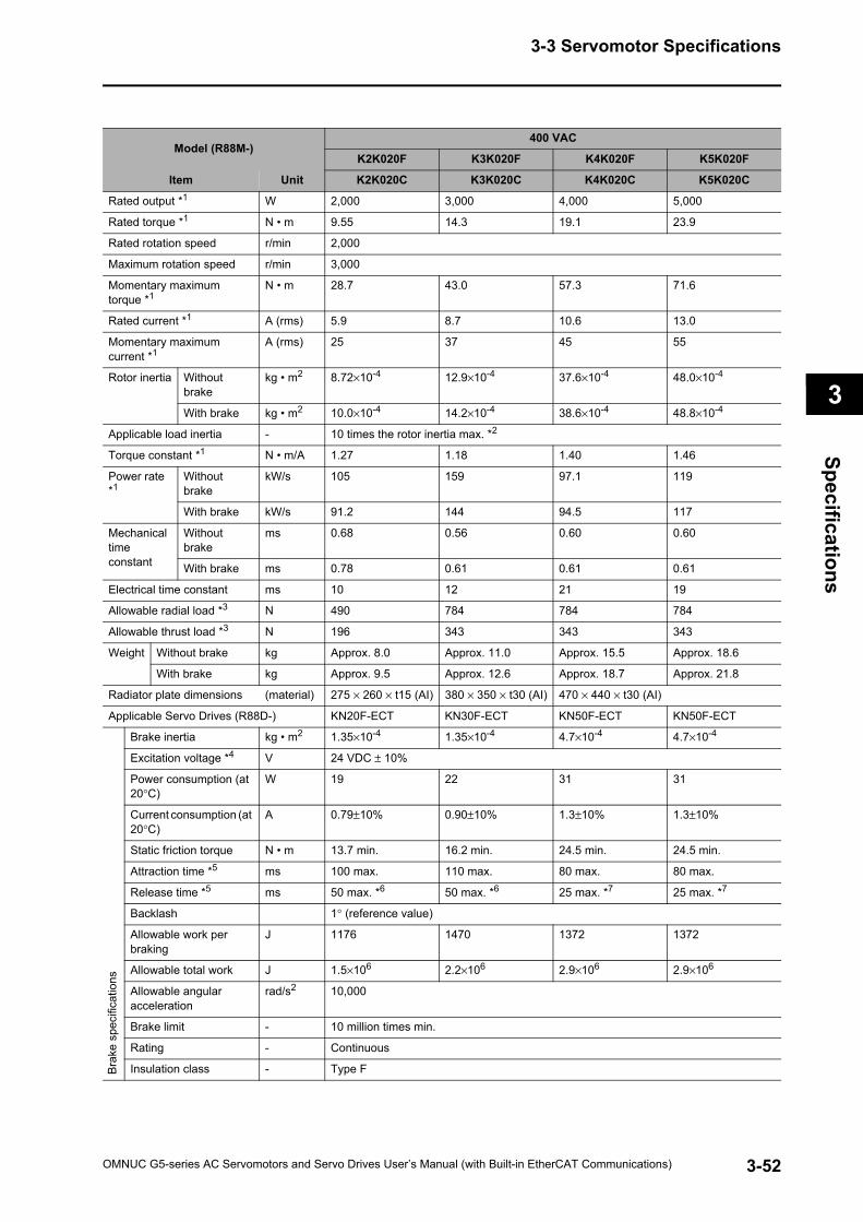
3-3 Servomotor Specifications
3
Specifications
Model (R88M-)400 VAC
K2K020F K3K020F K4K020F K5K020F
Item Unit K2K020C K3K020C K4K020C K5K020C
Rated output *1 W 2,000 3,000 4,000 5,000
Rated torque *1 N • m 9.55 14.3 19.1 23.9
Rated rotation speed r/min 2,000
Maximum rotation speed r/min 3,000
Momentary maximum torque *1
N • m 28.7 43.0 57.3 71.6
Rated current *1 A (rms) 5.9 8.7 10.6 13.0
Momentary maximum current *1
A (rms) 25 37 45 55
Rotor inertia Without brake
kg • m2 8.72×10⁻⁴ 12.9×10⁻⁴ 37.6×10⁻⁴ 48.0×10⁻⁴
With brake kg • m2 10.0×10⁻⁴ 14.2×10⁻⁴ 38.6×10⁻⁴ 48.8×10⁻⁴
Applicable load inertia - 10 times the rotor inertia max. *2
Torque constant *1 N • m/A 1.27 1.18 1.40 1.46
Power rate *1
Without brake
kW/s 105 159 97.1 119
With brake kW/s 91.2 144 94.5 117
Mechanical time constant
Without brake
ms 0.68 0.56 0.60 0.60
With brake ms 0.78 0.61 0.61 0.61
Electrical time constant ms 10 12 21 19
Allowable radial load *3 N 490 784 784 784
Allowable thrust load *3 N 196 343 343 343
Weight Without brake kg Approx. 8.0 Approx. 11.0 Approx. 15.5 Approx. 18.6
With brake kg Approx. 9.5 Approx. 12.6 Approx. 18.7 Approx. 21.8
Radiator plate dimensions (material) 275 × 260 × t15 (AI) 380 × 350 × t30 (AI) 470 × 440 × t30 (AI)
Applicable Servo Drives (R88D-) KN20F-ECT KN30F-ECT KN50F-ECT KN50F-ECT
Bra
ke s
peci
ficat
ions
Brake inertia kg • m2 1.35×10⁻⁴ 1.35×10⁻⁴ 4.7×10⁻⁴ 4.7×10⁻⁴
Excitation voltage *4 V 24 VDC ± 10%
Power consumption (at 20°C)
W 19 22 31 31
Current consumption (at 20°C)
A 0.79±10% 0.90±10% 1.3±10% 1.3±10%
Static friction torque N • m 13.7 min. 16.2 min. 24.5 min. 24.5 min.
Attraction time *5 ms 100 max. 110 max. 80 max. 80 max.
Release time *5 ms 50 max. *6 50 max. *6 25 max. *7 25 max. *7
Backlash 1° (reference value)
Allowable work per braking
J 1176 1470 1372 1372
Allowable total work J 1.5×10⁶ 2.2×10⁶ 2.9×10⁶ 2.9×10⁶
Allowable angular acceleration
rad/s2 10,000
Brake limit - 10 million times min.
Rating - Continuous
Insulation class - Type F
3-52OMNUC G5-series AC Servomotors and Servo Drives User’s Manual (with Built-in EtherCAT Communications)
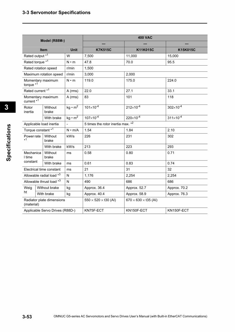
3-3 Servomotor Specifications
3
Spec
ifica
tions
Model (R88M-)400 VAC
--- --- ---Item Unit K7K515C K11K015C K15K015C
Rated output *1 W 7,500 11,000 15,000
Rated torque *1 N • m 47.8 70.0 95.5
Rated rotation speed r/min 1,500
Maximum rotation speed r/min 3,000 2,000
Momentary maximum torque *1
N • m 119.0 175.0 224.0
Rated current *1 A (rms) 22.0 27.1 33.1
Momentary maximum current *1
A (rms) 83 101 118
Rotor inertia
Without brake
kg • m2 101×10-4 212×10-4 302×10-4
With brake kg • m2 107×10-4 220×10-4 311×10-4
Applicable load inertia - 5 times the rotor inertia max. *2
Torque constant *1 N • m/A 1.54 1.84 2.10
Power rate *1
Without brake
kW/s 226 231 302
With brake kW/s 213 223 293
Mechanical time constant
Without brake
ms 0.58 0.80 0.71
With brake ms 0.61 0.83 0.74
Electrical time constant ms 21 31 32
Allowable radial load *3 N 1,176 2,254 2,254
Allowable thrust load *3 N 490 686 686
Weight
Without brake kg Approx. 36.4 Approx. 52.7 Approx. 70.2
With brake kg Approx. 40.4 Approx. 58.9 Approx. 76.3
Radiator plate dimensions (material)
550 × 520 × t30 (AI) 670 × 630 × t35 (AI)
Applicable Servo Drives (R88D-) KN75F-ECT KN150F-ECT KN150F-ECT
3-53 OMNUC G5-series AC Servomotors and Servo Drives User’s Manual (with Built-in EtherCAT Communications)
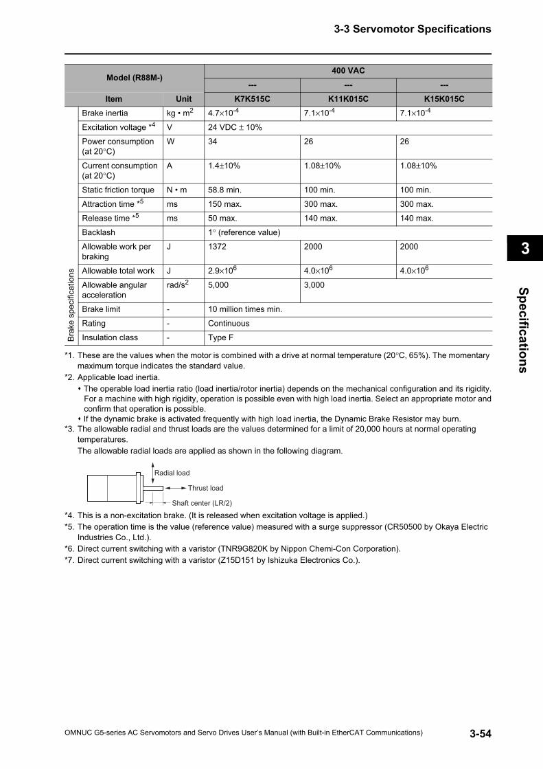
3-3 Servomotor Specifications
3
Specifications
*1. These are the values when the motor is combined with a drive at normal temperature (20°C, 65%). The momentary maximum torque indicates the standard value.*2. Applicable load inertia. The operable load inertia ratio (load inertia/rotor inertia) depends on the mechanical configuration and its rigidity.For a machine with high rigidity, operation is possible even with high load inertia. Select an appropriate motor andconfirm that operation is possible.
If the dynamic brake is activated frequently with high load inertia, the Dynamic Brake Resistor may burn.*3. The allowable radial and thrust loads are the values determined for a limit of 20,000 hours at normal operating
temperatures. The allowable radial loads are applied as shown in the following diagram.
*4. This is a non-excitation brake. (It is released when excitation voltage is applied.)*5. The operation time is the value (reference value) measured with a surge suppressor (CR50500 by Okaya Electric
Industries Co., Ltd.). *6. Direct current switching with a varistor (TNR9G820K by Nippon Chemi-Con Corporation). *7. Direct current switching with a varistor (Z15D151 by Ishizuka Electronics Co.).
Bra
ke s
peci
ficat
ions
Brake inertia kg • m2 4.7×10⁻⁴ 7.1×10⁻⁴ 7.1×10⁻⁴
Excitation voltage *4 V 24 VDC ± 10%
Power consumption (at 20°C)
W 34 26 26
Current consumption (at 20°C)
A 1.4±10% 1.08±10% 1.08±10%
Static friction torque N • m 58.8 min. 100 min. 100 min.
Attraction time *5 ms 150 max. 300 max. 300 max.
Release time *5 ms 50 max. 140 max. 140 max.
Backlash 1° (reference value)
Allowable work per braking
J 1372 2000 2000
Allowable total work J 2.9×10⁶ 4.0×10⁶ 4.0×10⁶
Allowable angular acceleration
rad/s2 5,000 3,000
Brake limit - 10 million times min.
Rating - Continuous
Insulation class - Type F
Model (R88M-)400 VAC
--- --- ---Item Unit K7K515C K11K015C K15K015C
Radial load
Thrust load
Shaft center (LR/2)
3-54OMNUC G5-series AC Servomotors and Servo Drives User’s Manual (with Built-in EtherCAT Communications)
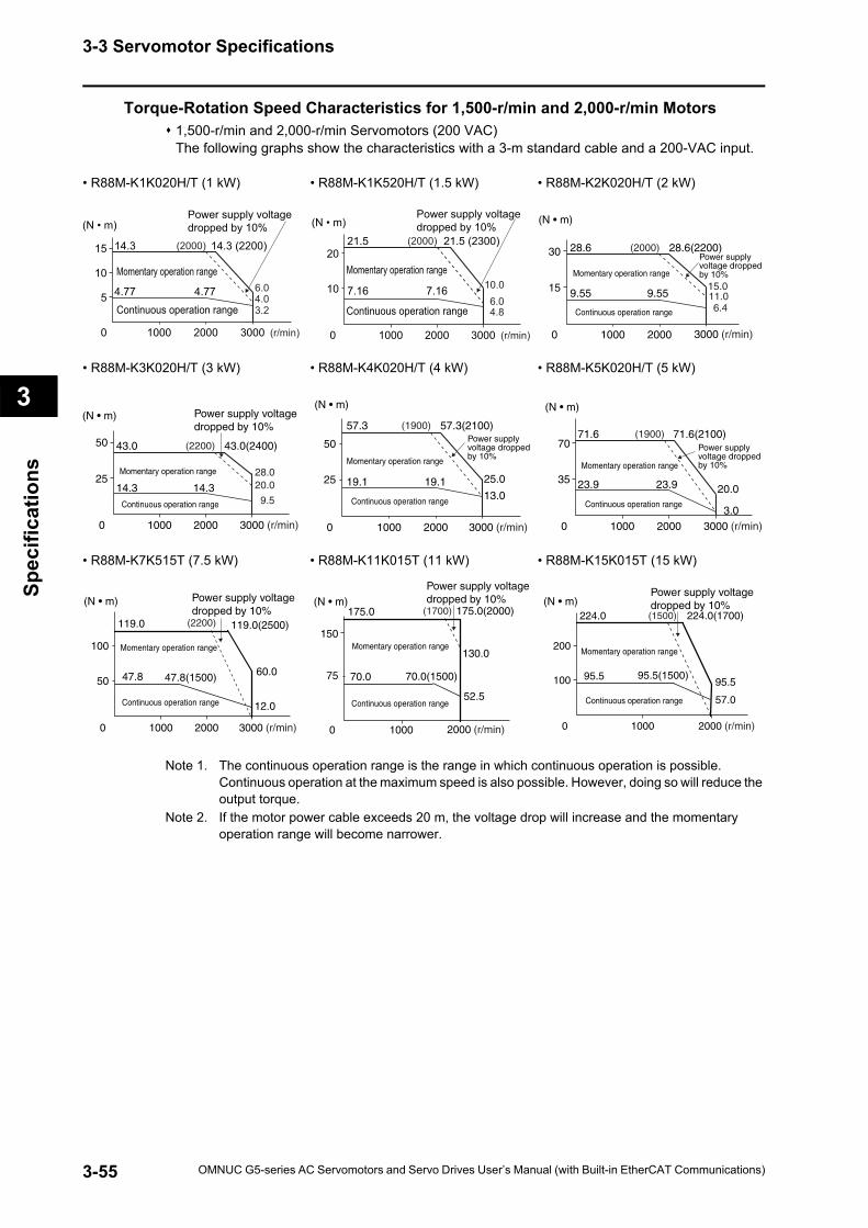
3-3 Servomotor Specifications
3
Spec
ifica
tions
Torque-Rotation Speed Characteristics for 1,500-r/min and 2,000-r/min Motors1,500-r/min and 2,000-r/min Servomotors (200 VAC) The following graphs show the characteristics with a 3-m standard cable and a 200-VAC input.
• R88M-K1K020H/T (1 kW) • R88M-K1K520H/T (1.5 kW) • R88M-K2K020H/T (2 kW)
• R88M-K3K020H/T (3 kW) • R88M-K4K020H/T (4 kW) • R88M-K5K020H/T (5 kW)
• R88M-K7K515T (7.5 kW) • R88M-K11K015T (11 kW) • R88M-K15K015T (15 kW)
Note 1. The continuous operation range is the range in which continuous operation is possible. Continuous operation at the maximum speed is also possible. However, doing so will reduce the output torque.
Note 2. If the motor power cable exceeds 20 m, the voltage drop will increase and the momentary operation range will become narrower.
(N • m)
0 1000 2000
5
10
15 14.3
4.77 4.77
14.3 (2200)
Momentary operation range
Continuous operation range
3000 (r/min)
Power supply voltage dropped by 10%
6.04.0
(2000)
3.2
(N • m)
10
0
2021.5
7.16 7.16
21.5 (2300)
1000 2000
Momentary operation range
Continuous operation range
3000 (r/min)
Power supply voltage dropped by 10%
10.06.0
(2000)
4.8
15
0
30 28.6
9.55 9.55
28.6(2200)
1000 2000
15.011.0
(2000)
6.4
Power supply voltage dropped by 10%
(N • m)
Momentary operation range
Continuous operation range
3000 (r/min)
25
0
50 43.0
14.3 14.3
43.0(2400)
1000 2000
28.0
(2200)
20.0
9.5
Power supply voltage dropped by 10%
Momentary operation range
(N • m)
Continuous operation range
3000 (r/min)
25
0
50
57.3
19.1 19.1
57.3(2100)
1000 2000
25.0
13.0
(1900)Power supply voltage dropped by 10%
(N • m)
Momentary operation range
Continuous operation range
3000 (r/min)
35
0
7071.6 71.6(2100)
23.9 23.9
1000 2000
20.0
3.0
(1900)Power supply voltage dropped by 10%
(N • m)
Momentary operation range
Continuous operation range
3000 (r/min)
50
0
100
119.0
47.8 47.8(1500)
119.0(2500)
1000 2000 3000 (r/min)
60.0
12.0
(2200)
Power supply voltage dropped by 10%
Momentary operation range
(N • m)
Continuous operation range
75
0
150
175.0
70.0 70.0(1500)
175.0(2000)
1000 2000 (r/min)
130.0
52.5
(1700)
Power supply voltage dropped by 10%
Momentary operation range
(N • m)
Continuous operation range
100
0
200
224.0
95.5 95.5(1500)
224.0(1700)
1000 2000 (r/min)
95.5
57.0
(1500)
Power supply voltage dropped by 10%
Momentary operation range
(N • m)
Continuous operation range
3-55 OMNUC G5-series AC Servomotors and Servo Drives User’s Manual (with Built-in EtherCAT Communications)
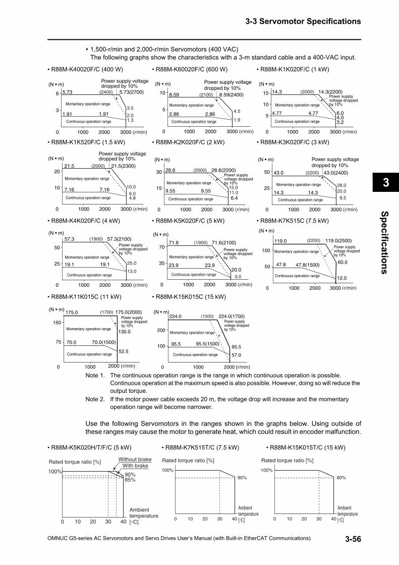
3-3 Servomotor Specifications
3
Specifications
1,500-r/min and 2,000-r/min Servomotors (400 VAC) The following graphs show the characteristics with a 3-m standard cable and a 400-VAC input.
• R88M-K40020F/C (400 W) • R88M-K60020F/C (600 W) • R88M-K1K020F/C (1 kW)
• R88M-K1K520F/C (1.5 kW) • R88M-K2K020F/C (2 kW) • R88M-K3K020F/C (3 kW)
• R88M-K4K020F/C (4 kW) • R88M-K5K020F/C (5 kW) • R88M-K7K515C (7.5 kW)
• R88M-K11K015C (11 kW) • R88M-K15K015C (15 kW)
Note 1. The continuous operation range is the range in which continuous operation is possible. Continuous operation at the maximum speed is also possible. However, doing so will reduce the output torque.
Note 2. If the motor power cable exceeds 20 m, the voltage drop will increase and the momentary operation range will become narrower.
Use the following Servomotors in the ranges shown in the graphs below. Using outside ofthese ranges may cause the motor to generate heat, which could result in encoder malfunction.
• R88M-K5K020H/T/F/C (5 kW) • R88M-K7K515T/C (7.5 kW) • R88M-K15K015T/C (15 kW)
0 1000 2000
3
6 5.73
1.91 1.91
5.73(2700)
3000 (r/min)
3.5
(2400)
2.01.3
Power supply voltage dropped by 10%(N • m)
Momentary operation range
Continuous operation range
0 1000 2000
5
10 8.59
2.86 2.86
8.59(2400)
3000 (r/min)
4.5
(2100)
1.9
Power supply voltage dropped by 10%
Momentary operation range
Continuous operation range
(N • m)
0 1000 2000
5
10
15 14.3
4.77 4.77
14.3(2200)
3000 (r/min)
6.04.03.2
(2000)Power supply voltage dropped by 10%
(N • m)
Momentary operation range
Continuous operation range
10
0
2021.5
7.16 7.16
21.5(2300)
1000 2000 3000 (r/min)
10.0
6.04.8
(2000)
Power supply voltage dropped by 10%(N • m)
Momentary operation range
Continuous operation range
Power supply voltage dropped by 10%
15
0
30 28.6
9.55 9.55
28.6(2200)
1000 2000 3000 (r/min)
15.011.06.4
(2000)
(N • m)
Momentary operation range
Continuous operation range
25
0
50 43.0
14.3 14.3
43.0(2400)
1000 2000 3000 (r/min)
28.020.09.5
(2200)
Power supply voltage dropped by 10%
(N • m)
Momentary operation range
Continuous operation range
25
0
50
57.3
19.1 19.1
57.3(2100)
1000 2000 3000 (r/min)
25.0
13.0
(1900)Power supply voltage dropped by 10%
Momentary operation range
(N • m)
Continuous operation range
35
0
7071.6
23.9 23.9
71.6(2100)
1000 2000 3000 (r/min)
20.03.0
(1900)Power supply voltage dropped by 10%
(N • m)
Momentary operation range
Continuous operation range
50
0
100
119.0
47.8 47.8(1500)
119.0(2500)
1000 2000 3000 (r/min)
60.0
12.0
(2200)Power supply voltage dropped by 10%
Momentary operation range
(N • m)
Continuous operation range
75
0
150
175.0
70.0 70.0(1500)
175.0(2000)
1000
130.0
52.5
(1700)Power supply voltage dropped by 10%
Momentary operation range
(N • m)
Continuous operation range
2000 (r/min)
100
0
200
224.0
95.5 95.5(1500)
224.0(1700)
1000 2000 (r/min)
95.5
57.0
(1500)Power supply voltage dropped by 10%
Momentary operation range
(N • m)
Continuous operation range
Rated torque ratio [%]
Ambient temperature [°C]
100%
85%90%
100 20 30 40
Without brakeWith brake
100%
90%
100 20 30 40
Rated torque ratio [%]
Ambient temperature [°C]
100%
90%
100 20 30 40
Rated torque ratio [%]
Ambient temperature [°C]
3-56OMNUC G5-series AC Servomotors and Servo Drives User’s Manual (with Built-in EtherCAT Communications)
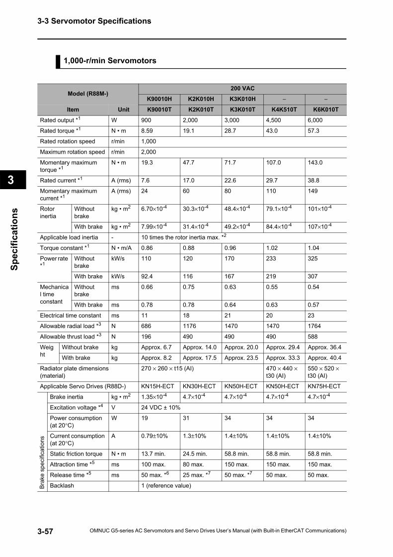
3-3 Servomotor Specifications
3
Spec
ifica
tions
1,000-r/min Servomotors
Model (R88M-)200 VAC
K90010H K2K010H K3K010H − −
Item Unit K90010T K2K010T K3K010T K4K510T K6K010T
Rated output *1 W 900 2,000 3,000 4,500 6,000
Rated torque *1 N • m 8.59 19.1 28.7 43.0 57.3
Rated rotation speed r/min 1,000
Maximum rotation speed r/min 2,000
Momentary maximum torque *1
N • m 19.3 47.7 71.7 107.0 143.0
Rated current *1 A (rms) 7.6 17.0 22.6 29.7 38.8
Momentary maximum current *1
A (rms) 24 60 80 110 149
Rotor inertia
Without brake
kg • m2 6.70×10⁻⁴ 30.3×10⁻⁴ 48.4×10⁻⁴ 79.1×10⁻⁴ 101×10-4
With brake kg • m2 7.99×10⁻⁴ 31.4×10⁻⁴ 49.2×10⁻⁴ 84.4×10⁻⁴ 107×10-4
Applicable load inertia - 10 times the rotor inertia max. *2
Torque constant *1 N • m/A 0.86 0.88 0.96 1.02 1.04
Power rate *1
Without brake
kW/s 110 120 170 233 325
With brake kW/s 92.4 116 167 219 307
Mechanical time constant
Without brake
ms 0.66 0.75 0.63 0.55 0.54
With brake ms 0.78 0.78 0.64 0.63 0.57
Electrical time constant ms 11 18 21 20 23
Allowable radial load *3 N 686 1176 1470 1470 1764
Allowable thrust load *3 N 196 490 490 490 588
Weight
Without brake kg Approx. 6.7 Approx. 14.0 Approx. 20.0 Approx. 29.4 Approx. 36.4
With brake kg Approx. 8.2 Approx. 17.5 Approx. 23.5 Approx. 33.3 Approx. 40.4
Radiator plate dimensions (material)
270 × 260 × t15 (AI) 470 × 440 × t30 (AI)
550 × 520 × t30 (AI)
Applicable Servo Drives (R88D-) KN15H-ECT KN30H-ECT KN50H-ECT KN50H-ECT KN75H-ECT
Bra
ke s
peci
ficat
ions
Brake inertia kg • m2 1.35×10⁻⁴ 4.7×10⁻⁴ 4.7×10⁻⁴ 4.7×10⁻⁴ 4.7×10⁻⁴
Excitation voltage *4 V 24 VDC ± 10%
Power consumption (at 20°C)
W 19 31 34 34 34
Current consumption (at 20°C)
A 0.79±10% 1.3±10% 1.4±10% 1.4±10% 1.4±10%
Static friction torque N • m 13.7 min. 24.5 min. 58.8 min. 58.8 min. 58.8 min.
Attraction time *5 ms 100 max. 80 max. 150 max. 150 max. 150 max.
Release time *5 ms 50 max. *6 25 max. *7 50 max. *7 50 max. 50 max.
Backlash 1 (reference value)
3-57 OMNUC G5-series AC Servomotors and Servo Drives User’s Manual (with Built-in EtherCAT Communications)
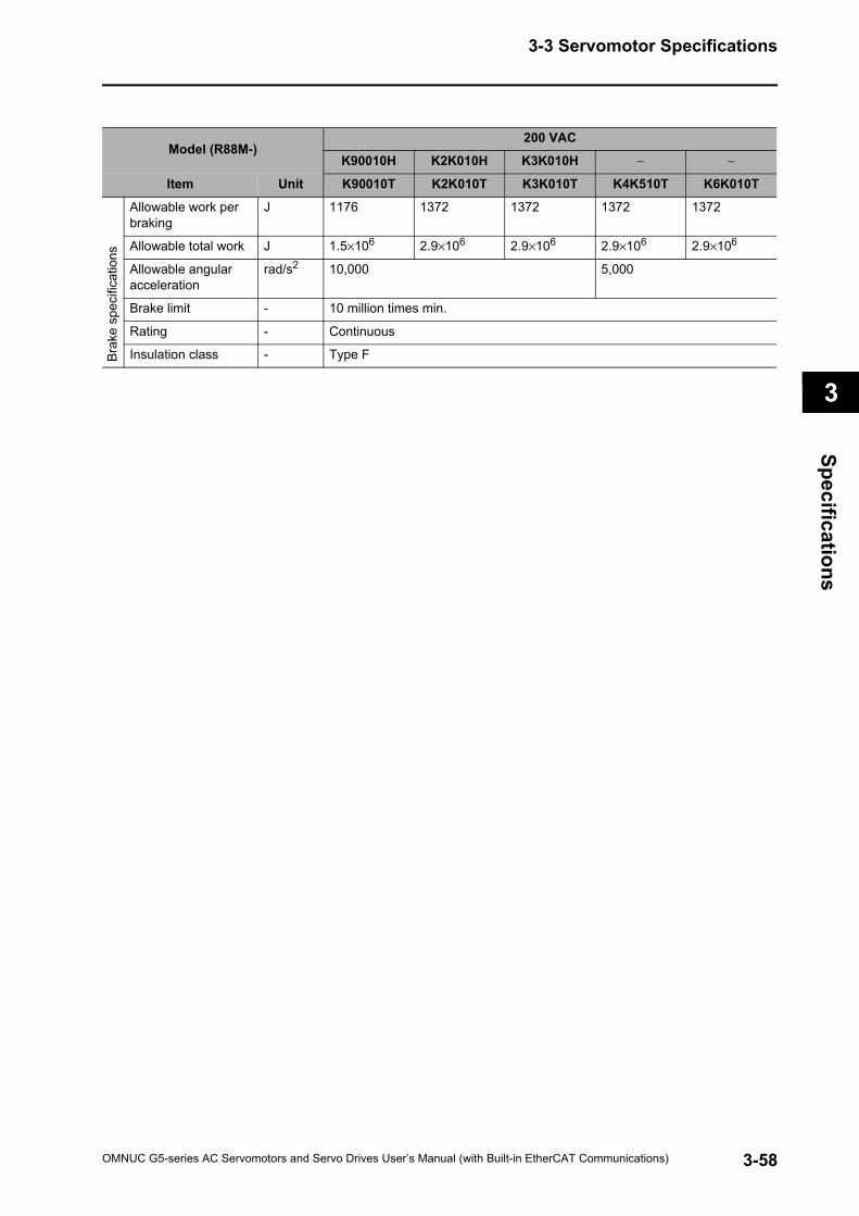
3-3 Servomotor Specifications
3
Specifications
Model (R88M-)200 VAC
K90010H K2K010H K3K010H − −
Item Unit K90010T K2K010T K3K010T K4K510T K6K010T
Bra
ke s
peci
ficat
ions
Allowable work per braking
J 1176 1372 1372 1372 1372
Allowable total work J 1.5×10⁶ 2.9×10⁶ 2.9×10⁶ 2.9×10⁶ 2.9×10⁶
Allowable angular acceleration
rad/s2 10,000 5,000
Brake limit - 10 million times min.
Rating - Continuous
Insulation class - Type F
3-58OMNUC G5-series AC Servomotors and Servo Drives User’s Manual (with Built-in EtherCAT Communications)
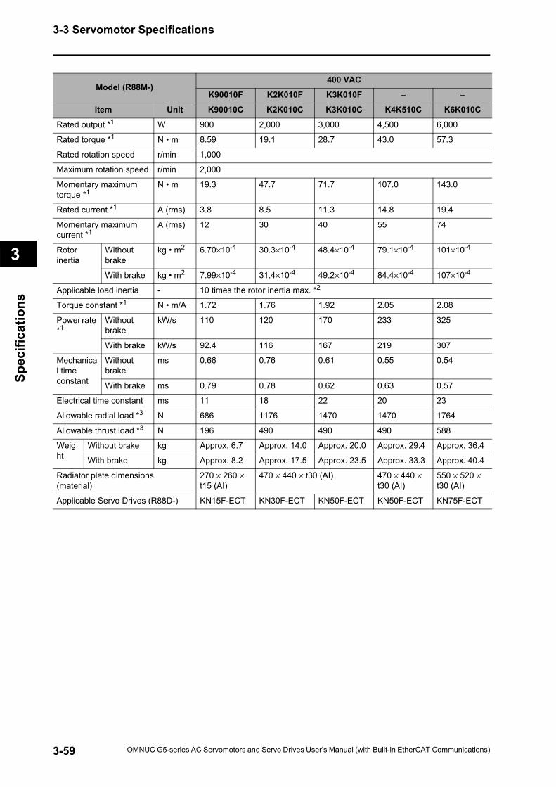
3-3 Servomotor Specifications
3
Spec
ifica
tions
Model (R88M-)400 VAC
K90010F K2K010F K3K010F − −
Item Unit K90010C K2K010C K3K010C K4K510C K6K010C
Rated output *1 W 900 2,000 3,000 4,500 6,000
Rated torque *1 N • m 8.59 19.1 28.7 43.0 57.3
Rated rotation speed r/min 1,000
Maximum rotation speed r/min 2,000
Momentary maximum torque *1
N • m 19.3 47.7 71.7 107.0 143.0
Rated current *1 A (rms) 3.8 8.5 11.3 14.8 19.4
Momentary maximum current *1
A (rms) 12 30 40 55 74
Rotor inertia
Without brake
kg • m2 6.70×10⁻⁴ 30.3×10⁻⁴ 48.4×10⁻⁴ 79.1×10⁻⁴ 101×10-4
With brake kg • m2 7.99×10⁻⁴ 31.4×10⁻⁴ 49.2×10⁻⁴ 84.4×10⁻⁴ 107×10-4
Applicable load inertia - 10 times the rotor inertia max. *2
Torque constant *1 N • m/A 1.72 1.76 1.92 2.05 2.08
Power rate *1
Without brake
kW/s 110 120 170 233 325
With brake kW/s 92.4 116 167 219 307
Mechanical time constant
Without brake
ms 0.66 0.76 0.61 0.55 0.54
With brake ms 0.79 0.78 0.62 0.63 0.57
Electrical time constant ms 11 18 22 20 23
Allowable radial load *3 N 686 1176 1470 1470 1764
Allowable thrust load *3 N 196 490 490 490 588
Weight
Without brake kg Approx. 6.7 Approx. 14.0 Approx. 20.0 Approx. 29.4 Approx. 36.4
With brake kg Approx. 8.2 Approx. 17.5 Approx. 23.5 Approx. 33.3 Approx. 40.4
Radiator plate dimensions (material)
270 × 260 × t15 (AI)
470 × 440 × t30 (AI) 470 × 440 × t30 (AI)
550 × 520 × t30 (AI)
Applicable Servo Drives (R88D-) KN15F-ECT KN30F-ECT KN50F-ECT KN50F-ECT KN75F-ECT
3-59 OMNUC G5-series AC Servomotors and Servo Drives User’s Manual (with Built-in EtherCAT Communications)
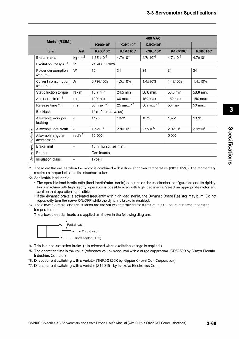
3-3 Servomotor Specifications
3
Specifications
*1. These are the values when the motor is combined with a drive at normal temperature (20°C, 65%). The momentary maximum torque indicates the standard value.
*2. Applicable load inertia. The operable load inertia ratio (load inertia/rotor inertia) depends on the mechanical configuration and its rigidity.For a machine with high rigidity, operation is possible even with high load inertia. Select an appropriate motor andconfirm that operation is possible.
If the dynamic brake is activated frequently with high load inertia, the Dynamic Brake Resistor may burn. Do notrepeatedly turn the servo ON/OFF while the dynamic brake is enabled.
*3. The allowable radial and thrust loads are the values determined for a limit of 20,000 hours at normal operating temperatures. The allowable radial loads are applied as shown in the following diagram.
*4. This is a non-excitation brake. (It is released when excitation voltage is applied.)*5. The operation time is the value (reference value) measured with a surge suppressor (CR50500 by Okaya Electric
Industries Co., Ltd.). *6. Direct current switching with a varistor (TNR9G820K by Nippon Chemi-Con Corporation). *7. Direct current switching with a varistor (Z15D151 by Ishizuka Electronics Co.).
Model (R88M-)400 VAC
K90010F K2K010F K3K010F − −
Item Unit K90010C K2K010C K3K010C K4K510C K6K010C
Brak
e sp
ecifi
catio
ns
Brake inertia kg • m2 1.35×10⁻⁴ 4.7×10⁻⁴ 4.7×10⁻⁴ 4.7×10⁻⁴ 4.7×10⁻⁴
Excitation voltage *4 V 24 VDC ± 10%
Power consumption (at 20°C)
W 19 31 34 34 34
Current consumption (at 20°C)
A 0.79±10% 1.3±10% 1.4±10% 1.4±10% 1.4±10%
Static friction torque N • m 13.7 min. 24.5 min. 58.8 min. 58.8 min. 58.8 min.
Attraction time *5 ms 100 max. 80 max. 150 max. 150 max. 150 max.
Release time *5 ms 50 max. *6 25 max. *7 50 max. *7 50 max. 50 max.
Backlash 1° (reference value)
Allowable work per braking
J 1176 1372 1372 1372 1372
Allowable total work J 1.5×10⁶ 2.9×10⁶ 2.9×10⁶ 2.9×10⁶ 2.9×10⁶
Allowable angular acceleration
rad/s2 10,000 5,000
Brake limit - 10 million times min.
Rating - Continuous
Insulation class - Type F
Radial load
Thrust load
Shaft center (LR/2)
3-60OMNUC G5-series AC Servomotors and Servo Drives User’s Manual (with Built-in EtherCAT Communications)
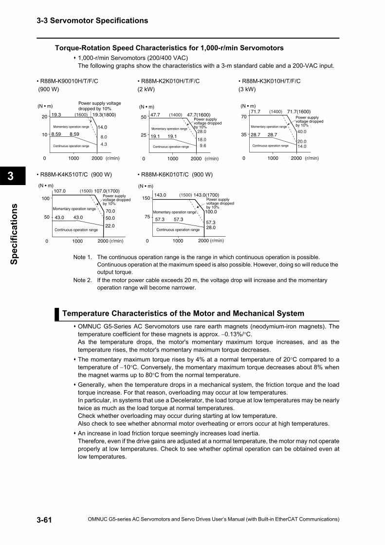
3-3 Servomotor Specifications
3
Spec
ifica
tions
Torque-Rotation Speed Characteristics for 1,000-r/min Servomotors1,000-r/min Servomotors (200/400 VAC) The following graphs show the characteristics with a 3-m standard cable and a 200-VAC input.
• R88M-K90010H/T/F/C • R88M-K2K010H/T/F/C • R88M-K3K010H/T/F/C (900 W) (2 kW) (3 kW)
• R88M-K4K510T/C (900 W) • R88M-K6K010T/C (900 W)
Note 1. The continuous operation range is the range in which continuous operation is possible. Continuous operation at the maximum speed is also possible. However, doing so will reduce the output torque.
Note 2. If the motor power cable exceeds 20 m, the voltage drop will increase and the momentary operation range will become narrower.
Temperature Characteristics of the Motor and Mechanical SystemOMNUC G5-Series AC Servomotors use rare earth magnets (neodymium-iron magnets). Thetemperature coefficient for these magnets is approx. −0.13%/°C.As the temperature drops, the motor's momentary maximum torque increases, and as thetemperature rises, the motor's momentary maximum torque decreases.The momentary maximum torque rises by 4% at a normal temperature of 20°C compared to atemperature of −10°C. Conversely, the momentary maximum torque decreases about 8% whenthe magnet warms up to 80°C from the normal temperature.Generally, when the temperature drops in a mechanical system, the friction torque and the loadtorque increase. For that reason, overloading may occur at low temperatures.In particular, in systems that use a Decelerator, the load torque at low temperatures may be nearlytwice as much as the load torque at normal temperatures.Check whether overloading may occur during starting at low temperature.Also check to see whether abnormal motor overheating or errors occur at high temperatures.An increase in load friction torque seemingly increases load inertia.Therefore, even if the drive gains are adjusted at a normal temperature, the motor may not operateproperly at low temperatures. Check to see whether optimal operation can be obtained even atlow temperatures.
10
0
20 19.3(1800)19.3
8.598.59
1000 2000 (r/min)
14.0
8.0
4.3
(1600)
Power supply voltage dropped by 10%(N • m)
Momentary operation range
Continuous operation range
25
0
50
1000 2000 (r/min)
19.119.1
47.7(1600)47.7
28.0
18.09.6
(1400)Power supply voltage dropped by 10%
(N • m)
Momentary operation range
Continuous operation range
35
0
70
1000 2000 (r/min)
28.728.7
71.7(1600)71.7
40.0
20.014.0
(1400)Power supply voltage dropped by 10%
(N • m)
Momentary operation range
Continuous operation range
50
0
100
107.0
43.0 43.0
107.0(1700)
1000 2000 (r/min)
50.0
70.0
(1500)Power supply voltage dropped by 10%
Momentary operation range
(N • m)
Continuous operation range22.0
75
0
150143.0
57.3 57.3
143.0(1700)
1000 2000 (r/min)
57.3
100.0
(1500)Power supply voltage dropped by 10%
Momentary operation range
(N • m)
Continuous operation range 28.0
3-61 OMNUC G5-series AC Servomotors and Servo Drives User’s Manual (with Built-in EtherCAT Communications)
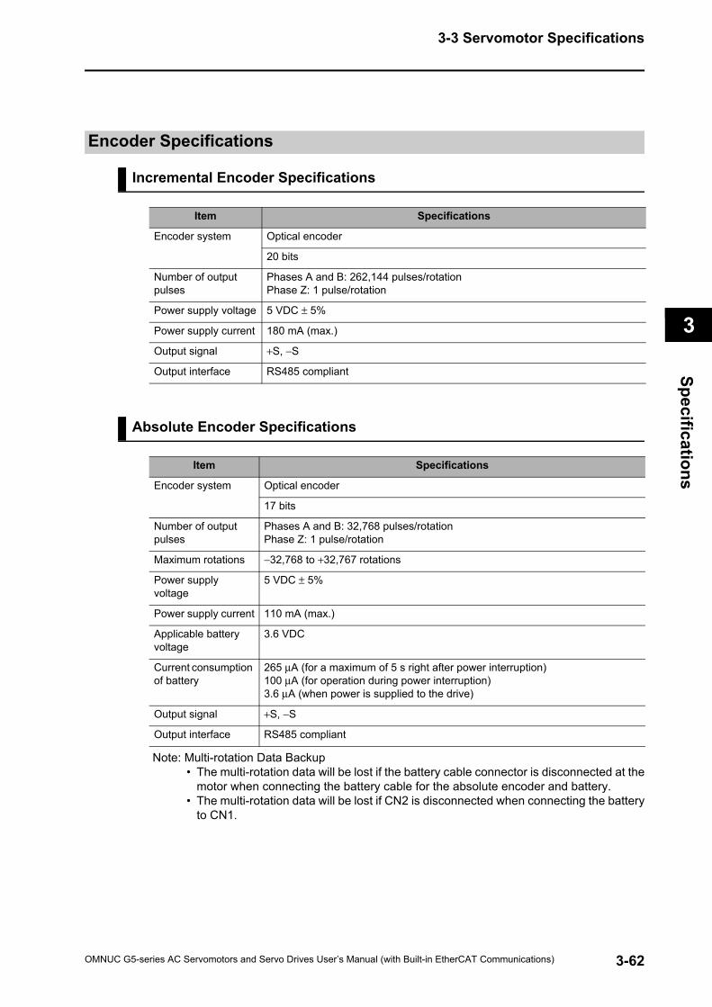
3-3 Servomotor Specifications
3
Specifications
Encoder Specifications
Incremental Encoder Specifications
Absolute Encoder Specifications
Note: Multi-rotation Data Backup• The multi-rotation data will be lost if the battery cable connector is disconnected at the
motor when connecting the battery cable for the absolute encoder and battery. • The multi-rotation data will be lost if CN2 is disconnected when connecting the battery
to CN1.
Item Specifications
Encoder system Optical encoder
20 bits
Number of output pulses
Phases A and B: 262,144 pulses/rotationPhase Z: 1 pulse/rotation
Power supply voltage 5 VDC ± 5%
Power supply current 180 mA (max.)
Output signal +S, −S
Output interface RS485 compliant
Item Specifications
Encoder system Optical encoder
17 bits
Number of output pulses
Phases A and B: 32,768 pulses/rotation Phase Z: 1 pulse/rotation
Maximum rotations −32,768 to +32,767 rotations
Power supply voltage
5 VDC ± 5%
Power supply current 110 mA (max.)
Applicable battery voltage
3.6 VDC
Current consumption of battery
265 µA (for a maximum of 5 s right after power interruption)100 µA (for operation during power interruption)3.6 µA (when power is supplied to the drive)
Output signal +S, −S
Output interface RS485 compliant
3-62OMNUC G5-series AC Servomotors and Servo Drives User’s Manual (with Built-in EtherCAT Communications)
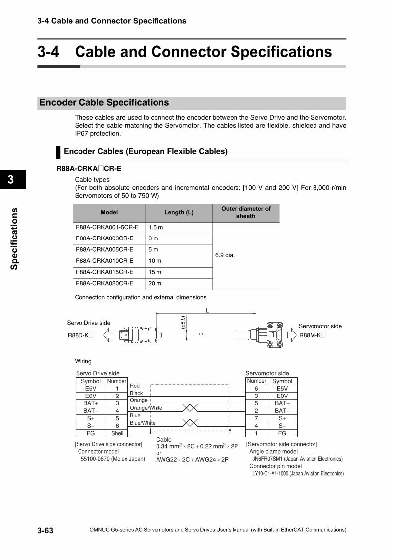
3-4 Cable and Connector Specifications
3
Spec
ifica
tions
3-4 Cable and Connector Specifications
Encoder Cable Specifications
These cables are used to connect the encoder between the Servo Drive and the Servomotor.Select the cable matching the Servomotor. The cables listed are flexible, shielded and haveIP67 protection.
Encoder Cables (European Flexible Cables)
R88A-CRKA@CR-E Cable types(For both absolute encoders and incremental encoders: [100 V and 200 V] For 3,000-r/minServomotors of 50 to 750 W)
Connection configuration and external dimensions
Wiring
Model Length (L) Outer diameter of sheath
R88A-CRKA001-5CR-E 1.5 m
6.9 dia.
R88A-CRKA003CR-E 3 m
R88A-CRKA005CR-E 5 m
R88A-CRKA010CR-E 10 m
R88A-CRKA015CR-E 15 m
R88A-CRKA020CR-E 20 m
L
(φ6.
9)
Servo Drive side Servomotor side
R88D-K@ R88M-K@
SymbolServo Drive side
E5V 1E0V 2
BAT+ 3BAT− 4
S+ 5S− 6FG Shell
Black
Cable 0.34 mm2 × 2C + 0.22 mm2 × 2PorAWG22 × 2C + AWG24 × 2P
6 E5VSymbol
Servomotor side
35274
E0VBAT+BAT−
S+S−FG1
[Servomotor side connector] Angle clamp model JN6FR07SM1 (Japan Aviation Electronics) Connector pin model LY10-C1-A1-1000 (Japan Aviation Electronics)
[Servo Drive side connector] Connector model 55100-0670 (Molex Japan)
Red
Orange
Orange/WhiteBlueBlue/White
Number Number
3-63 OMNUC G5-series AC Servomotors and Servo Drives User’s Manual (with Built-in EtherCAT Communications)
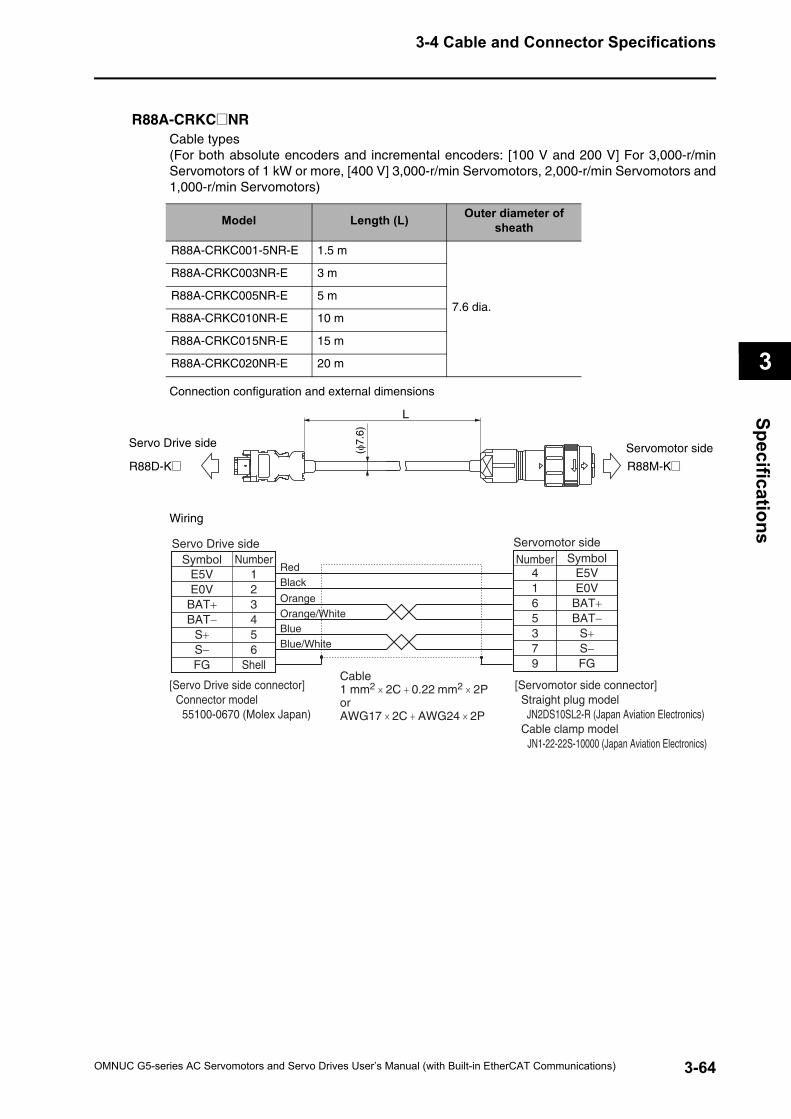
3-4 Cable and Connector Specifications
3
Specifications
R88A-CRKC@NR Cable types(For both absolute encoders and incremental encoders: [100 V and 200 V] For 3,000-r/minServomotors of 1 kW or more, [400 V] 3,000-r/min Servomotors, 2,000-r/min Servomotors and1,000-r/min Servomotors)
Connection configuration and external dimensions
Wiring
Model Length (L) Outer diameter of sheath
R88A-CRKC001-5NR-E 1.5 m
7.6 dia.
R88A-CRKC003NR-E 3 m
R88A-CRKC005NR-E 5 m
R88A-CRKC010NR-E 10 m
R88A-CRKC015NR-E 15 m
R88A-CRKC020NR-E 20 m
L
(φ7.
6)
Servo Drive side Servomotor side
R88D-K@ R88M-K@
SymbolServo Drive side
E5V 1E0V 2
BAT+ 3BAT− 4
S+ 5S− 6FG Shell
Cable1 mm2 × 2C + 0.22 mm2 × 2PorAWG17 × 2C + AWG24 × 2P
4 E5VSymbol
Servomotor side
16537
E0VBAT+BAT−
S+S−FG9
[Servomotor side connector] Straight plug model JN2DS10SL2-R (Japan Aviation Electronics) Cable clamp model JN1-22-22S-10000 (Japan Aviation Electronics)
[Servo Drive side connector] Connector model 55100-0670 (Molex Japan)
OrangeOrange/WhiteBlueBlue/White
BlackRed
Number Number
3-64OMNUC G5-series AC Servomotors and Servo Drives User’s Manual (with Built-in EtherCAT Communications)
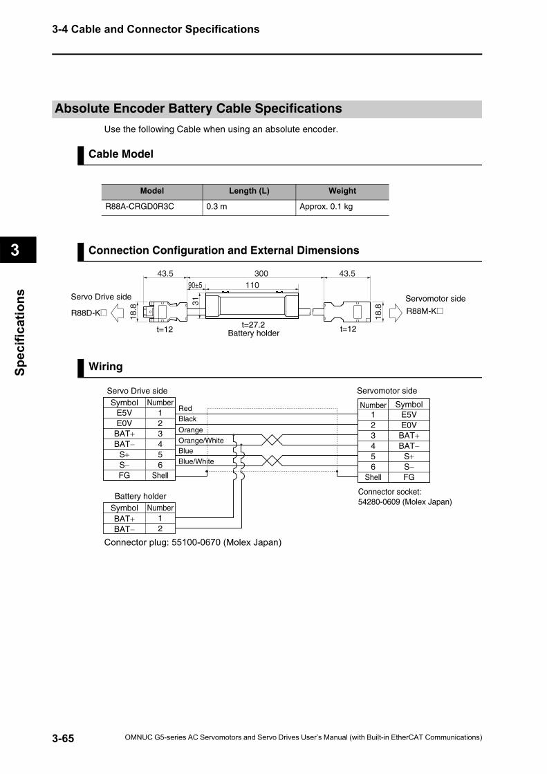
3-4 Cable and Connector Specifications
3
Spec
ifica
tions
Absolute Encoder Battery Cable Specifications
Use the following Cable when using an absolute encoder.
Cable Model
Connection Configuration and External Dimensions
Wiring
Connector plug: 55100-0670 (Molex Japan)
Model Length (L) Weight
R88A-CRGD0R3C 0.3 m Approx. 0.1 kg
Servo Drive side Servomotor side
R88D-K@ R88M-K@
Battery holder t=12t=12
43.530011090±5
43.5
8.81
8.81
13
t=27.2
SymbolServo Drive side
E5V 1E0V 2
BAT+ 3BAT− 4
S+ 5S− 6FG Shell
1 E5VSymbol
Servomotor side
23456
E0VBAT+BAT−
S+S−FGShell
Connector socket: 54280-0609 (Molex Japan)
OrangeOrange/WhiteBlueBlue/White
BlackRed
Number Number
Battery holder Symbol
12
BAT+BAT−
Number
3-65 OMNUC G5-series AC Servomotors and Servo Drives User’s Manual (with Built-in EtherCAT Communications)

3-4 Cable and Connector Specifications
3
Specifications
Motor Power Cable Specifications
These cables connect the Servo Drive and the Servomotor. Select the cable matching theServomotor.
The cables listed are flexible, shielded and have IP67 protection.
Power Cables without Brakes (European Flexible Cables)
R88A-CAKA@SR-E
Cable types[100 V and 200 V] (For 3,000-r/min Servomotors of 50 to 750 W)
Connection configuration and external dimensions
Wiring
Note: For servomotors with brake a separate cable R88A-CAKA@@@BR-E is needed.
Model Length (L) Outer diameter of sheath
R88A-CAKA001-5SR-E 1.5 m
6.7 dia.
R88A-CAKA003SR-E 3 m
R88A-CAKA005SR-E 5 m
R88A-CAKA010SR-E 10 m
R88A-CAKA015SR-E 15 m
R88A-CAKA020SR-E 20 m
(50) L
(φ6.
7)
Servo Drive side Servomotor side
R88D-K@ R88M-K@
1234
Phase UPhase VPhase W
FG
SymbolServo Drive side
RedWhiteBlueGreen/Yellow
Cable0.5 mm2 × 4C or AWG20 × 4C
M4 crimp terminal
Servomotor side
[Servomotor side connector]
Angle plug model
JN8FT04SJ1 (Japan Aviation Electronics)
Connector pin model
ST-TMH-S-C1B-3500-A534G (Japan Aviation Electronics)
Number
3-66OMNUC G5-series AC Servomotors and Servo Drives User’s Manual (with Built-in EtherCAT Communications)
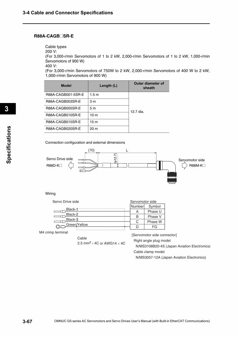
3-4 Cable and Connector Specifications
3
Spec
ifica
tions
R88A-CAGB@SR-E
Cable types200 V:(For 3,000-r/min Servomotors of 1 to 2 kW, 2,000-r/min Servomotors of 1 to 2 kW, 1,000-r/minServomotors of 900 W)400 V:(For 3,000-r/min Servomotors of 750W to 2 kW, 2,000-r/min Servomotors of 400 W to 2 kW,1,000-r/min Servomotors of 900 W)
Connection configuration and external dimensions
Wiring
Model Length (L) Outer diameter of sheath
R88A-CAGB001-5SR-E 1.5 m
12.7 dia.
R88A-CAGB003SR-E 3 m
R88A-CAGB005SR-E 5 m
R88A-CAGB010SR-E 10 m
R88A-CAGB015SR-E 15 m
R88A-CAGB020SR-E 20 m
(70) L
(φ12
.7)
Servo Drive side Servomotor side
R88D-K@ R88M-K@
NumberABCD
Phase UPhase VPhase W
FG
SymbolServo Drive side
Black-1Black-2Black-3Green/Yellow
Cable 2.5 mm2 × 4C or AWG14 × 4C
M4 crimp terminal
Servomotor side
[Servomotor side connector]
Right angle plug model
N/MS3108B20-4S (Japan Aviation Electronics)
Cable clamp model
N/MS3057-12A (Japan Aviation Electronics)
3-67 OMNUC G5-series AC Servomotors and Servo Drives User’s Manual (with Built-in EtherCAT Communications)
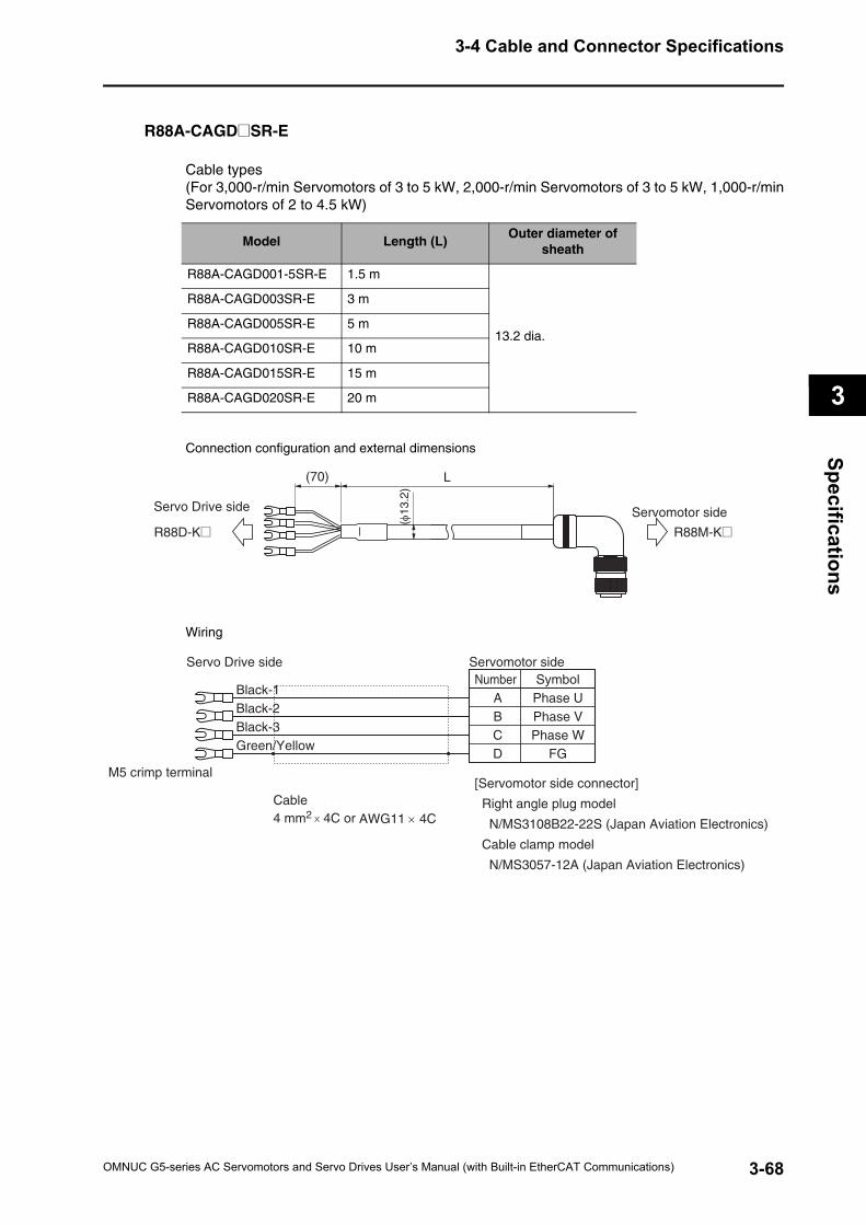
3-4 Cable and Connector Specifications
3
Specifications
R88A-CAGD@SR-E
Cable types(For 3,000-r/min Servomotors of 3 to 5 kW, 2,000-r/min Servomotors of 3 to 5 kW, 1,000-r/minServomotors of 2 to 4.5 kW)
Connection configuration and external dimensions
Wiring
Model Length (L)Outer diameter of
sheath
R88A-CAGD001-5SR-E 1.5 m
13.2 dia.
R88A-CAGD003SR-E 3 m
R88A-CAGD005SR-E 5 m
R88A-CAGD010SR-E 10 m
R88A-CAGD015SR-E 15 m
R88A-CAGD020SR-E 20 m
(70) L
(φ13
.2)
Servo Drive side Servomotor side
R88D-K@ R88M-K@
ABCD
Phase UPhase VPhase W
FG
SymbolNumberServo Drive side
Black-1Black-2Black-3Green/Yellow
Cable4 mm2 × 4C or AWG11 × 4C
M5 crimp terminal
Servomotor side
[Servomotor side connector]
Right angle plug model
N/MS3108B22-22S (Japan Aviation Electronics)
Cable clamp model
N/MS3057-12A (Japan Aviation Electronics)
3-68OMNUC G5-series AC Servomotors and Servo Drives User’s Manual (with Built-in EtherCAT Communications)
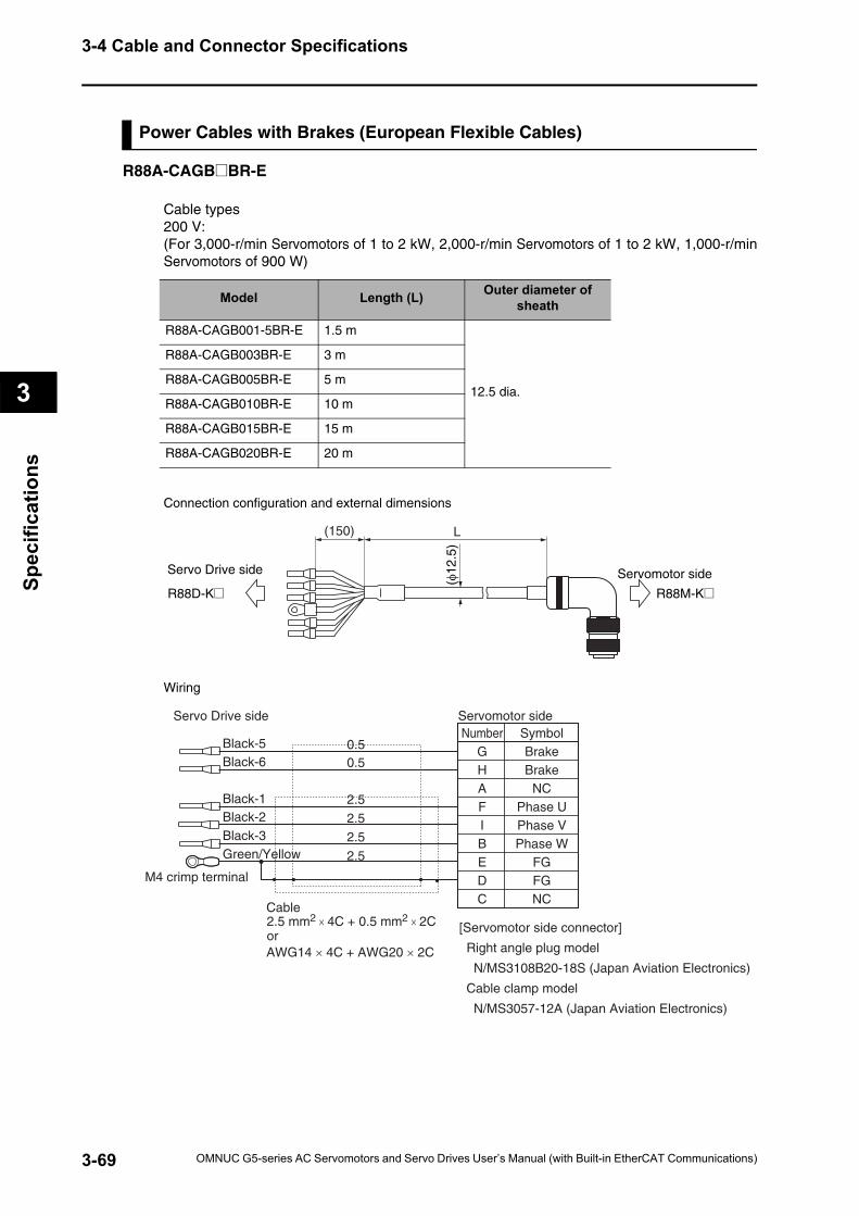
3-4 Cable and Connector Specifications
3
Spec
ifica
tions
Power Cables with Brakes (European Flexible Cables)
R88A-CAGB@BR-E
Cable types200 V:(For 3,000-r/min Servomotors of 1 to 2 kW, 2,000-r/min Servomotors of 1 to 2 kW, 1,000-r/minServomotors of 900 W)
Connection configuration and external dimensions
Wiring
Model Length (L) Outer diameter of sheath
R88A-CAGB001-5BR-E 1.5 m
12.5 dia.
R88A-CAGB003BR-E 3 m
R88A-CAGB005BR-E 5 m
R88A-CAGB010BR-E 10 m
R88A-CAGB015BR-E 15 m
R88A-CAGB020BR-E 20 m
L(150)
(φ12
.5)
Servo Drive side Servomotor side
R88D-K@ R88M-K@
NumberGHAF
BrakeBrake
NCPhase U
SymbolServo Drive side
Black-5Black-6
Black-1
IBEDC
Phase WFGFGNC
Phase VBlack-3Green/Yellow
Black-2
Servomotor side
Cable 2.5 mm2 × 4C + 0.5 mm2 × 2C orAWG14 × 4C + AWG20 × 2C
M4 crimp terminal
[Servomotor side connector]
Right angle plug model
N/MS3108B20-18S (Japan Aviation Electronics)
Cable clamp model
N/MS3057-12A (Japan Aviation Electronics)
0.50.5
2.52.52.52.5
3-69 OMNUC G5-series AC Servomotors and Servo Drives User’s Manual (with Built-in EtherCAT Communications)
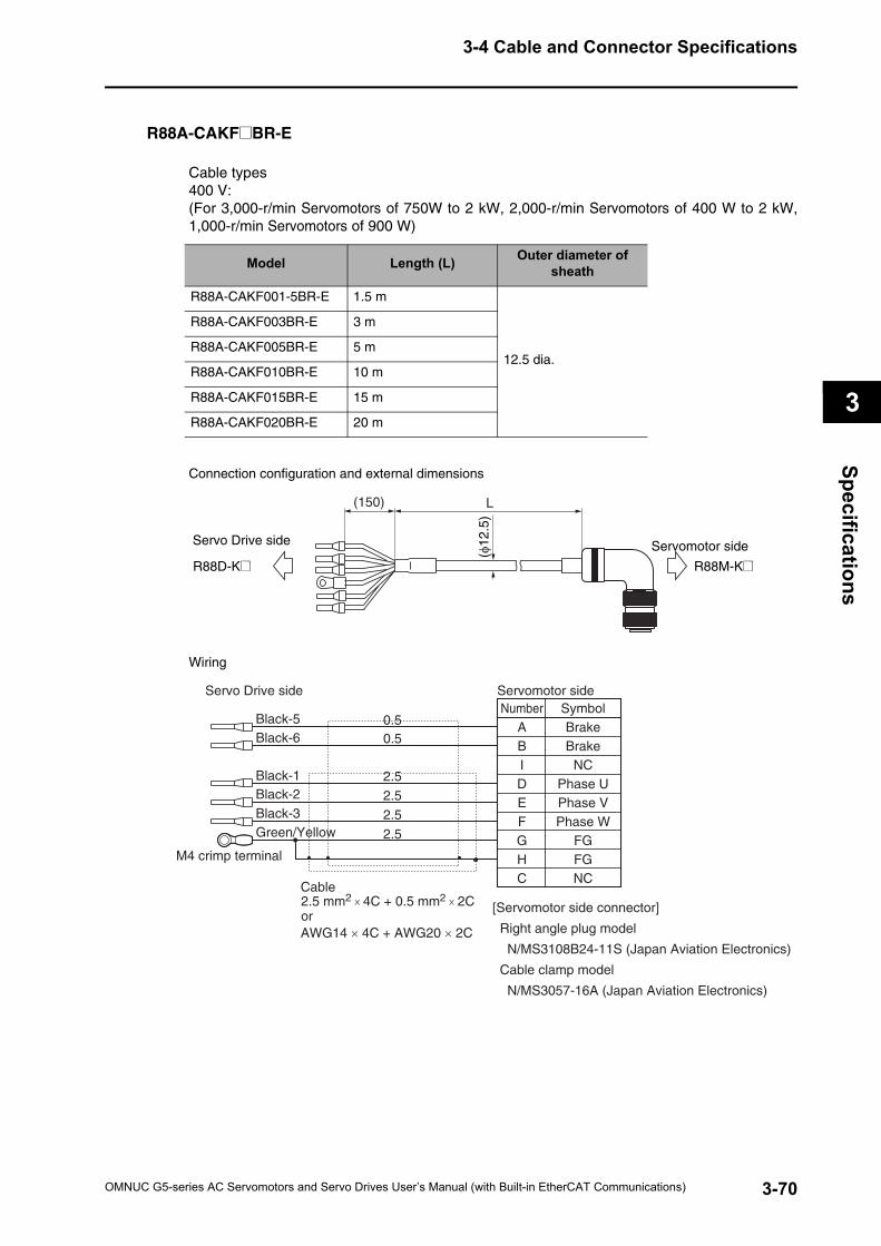
3-4 Cable and Connector Specifications
3
Specifications
R88A-CAKF@BR-E
Cable types400 V: (For 3,000-r/min Servomotors of 750W to 2 kW, 2,000-r/min Servomotors of 400 W to 2 kW,1,000-r/min Servomotors of 900 W)
Connection configuration and external dimensions
Wiring
Model Length (L) Outer diameter of sheath
R88A-CAKF001-5BR-E 1.5 m
12.5 dia.
R88A-CAKF003BR-E 3 m
R88A-CAKF005BR-E 5 m
R88A-CAKF010BR-E 10 m
R88A-CAKF015BR-E 15 m
R88A-CAKF020BR-E 20 m
L(150)(φ
12.5
)
Servo Drive side Servomotor side
R88D-K@ R88M-K@
NumberABID
BrakeBrake
NCPhase U
SymbolServo Drive side
Black-5Black-6
Black-1
EFGHC
Phase WFGFGNC
Phase VBlack-3Green/Yellow
Black-2
Servomotor side
Cable 2.5 mm2 × 4C + 0.5 mm2 × 2C orAWG14 × 4C + AWG20 × 2C
M4 crimp terminal
[Servomotor side connector]
Right angle plug model
N/MS3108B24-11S (Japan Aviation Electronics)
Cable clamp model
N/MS3057-16A (Japan Aviation Electronics)
0.50.5
2.52.52.52.5
3-70OMNUC G5-series AC Servomotors and Servo Drives User’s Manual (with Built-in EtherCAT Communications)
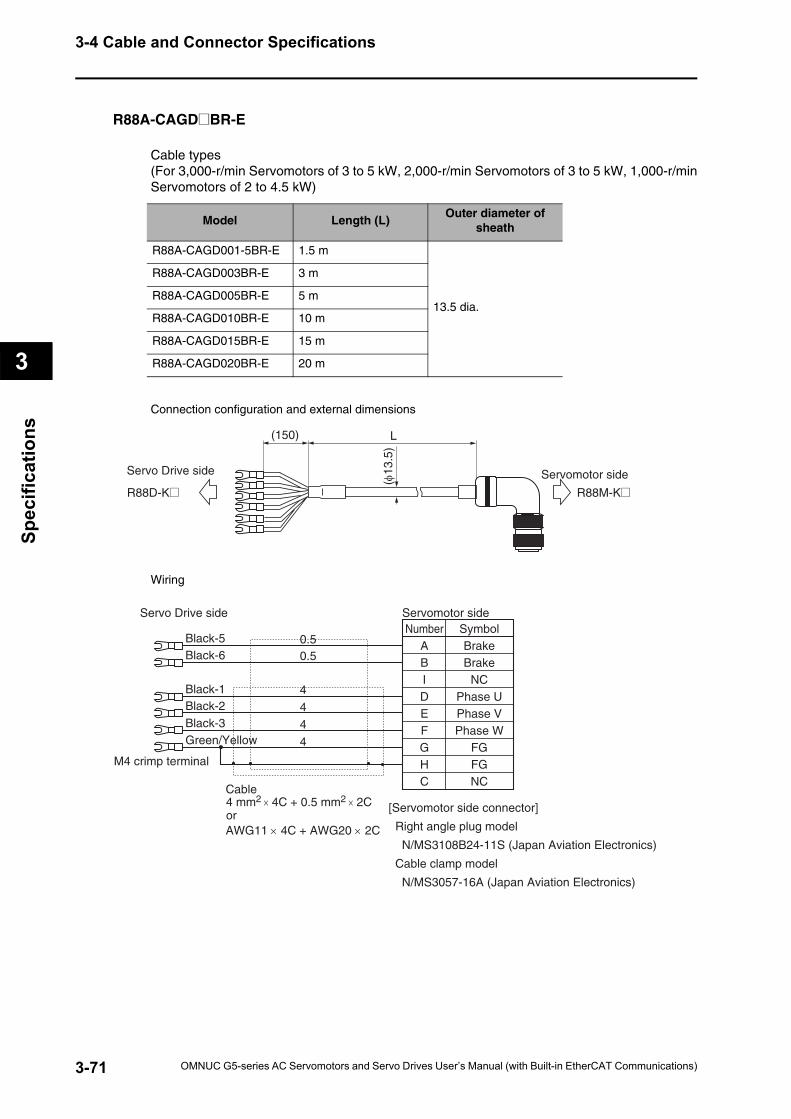
3-4 Cable and Connector Specifications
3
Spec
ifica
tions
R88A-CAGD@BR-E
Cable types(For 3,000-r/min Servomotors of 3 to 5 kW, 2,000-r/min Servomotors of 3 to 5 kW, 1,000-r/minServomotors of 2 to 4.5 kW)
Connection configuration and external dimensions
Wiring
Model Length (L)Outer diameter of
sheath
R88A-CAGD001-5BR-E 1.5 m
13.5 dia.
R88A-CAGD003BR-E 3 m
R88A-CAGD005BR-E 5 m
R88A-CAGD010BR-E 10 m
R88A-CAGD015BR-E 15 m
R88A-CAGD020BR-E 20 m
L(150)
(φ13
.5)
Servo Drive side Servomotor side
R88D-K@ R88M-K@
NumberABID
BrakeBrake
NCPhase U
SymbolServo Drive side
Black-5Black-6
Black-1
EFGHC
Phase WFGFGNC
Phase VBlack-3Green/Yellow
Black-2
Servomotor side
Cable 4 mm2 × 4C + 0.5 mm2 × 2C orAWG11 × 4C + AWG20 × 2C
M4 crimp terminal
[Servomotor side connector]
Right angle plug model
N/MS3108B24-11S (Japan Aviation Electronics)
Cable clamp model
N/MS3057-16A (Japan Aviation Electronics)
0.50.5
4444
3-71 OMNUC G5-series AC Servomotors and Servo Drives User’s Manual (with Built-in EtherCAT Communications)
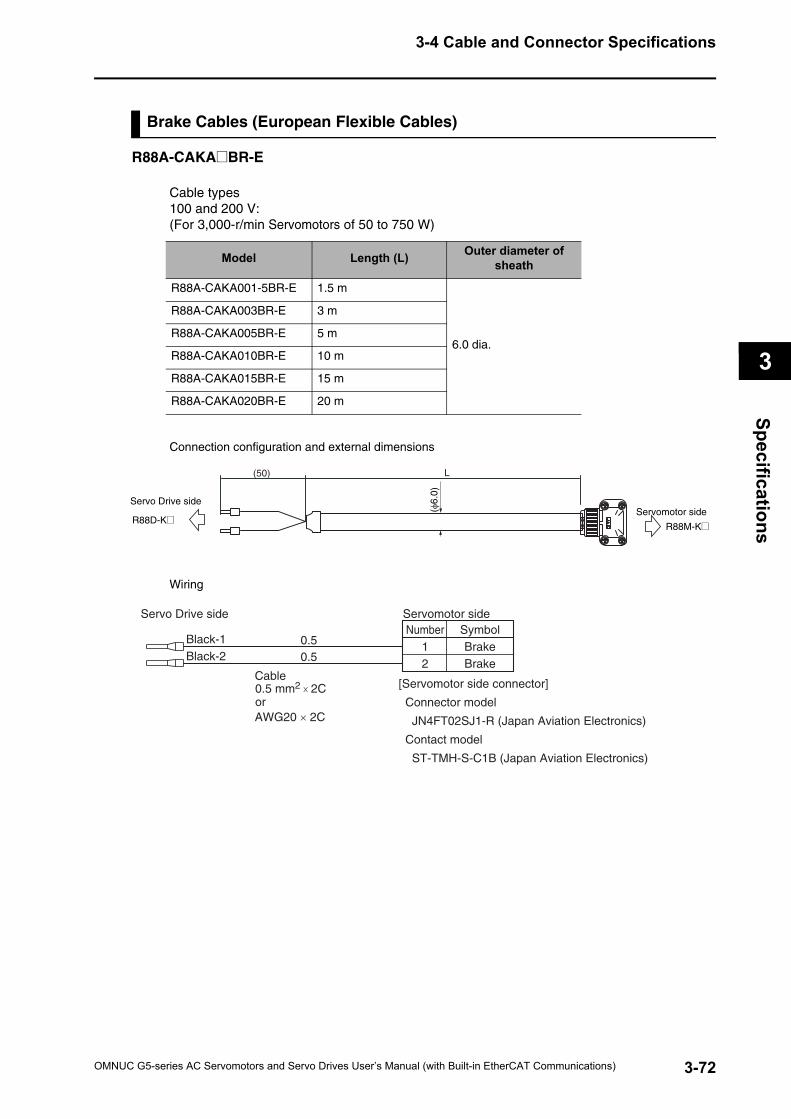
3-4 Cable and Connector Specifications
3
Specifications
Brake Cables (European Flexible Cables)
R88A-CAKA@BR-E
Cable types100 and 200 V:(For 3,000-r/min Servomotors of 50 to 750 W)
Connection configuration and external dimensions
Wiring
Model Length (L) Outer diameter of sheath
R88A-CAKA001-5BR-E 1.5 m
6.0 dia.
R88A-CAKA003BR-E 3 m
R88A-CAKA005BR-E 5 m
R88A-CAKA010BR-E 10 m
R88A-CAKA015BR-E 15 m
R88A-CAKA020BR-E 20 m
(φ6.
0)
(50) L
Servo Drive side
R88D-K@Servomotor side
R88M-K@
Number12
BrakeBrake
SymbolServo Drive side
Black-1Black-2
Servomotor side
Cable 0.5 mm2 × 2C orAWG20 × 2C
[Servomotor side connector]
Connector model
JN4FT02SJ1-R (Japan Aviation Electronics)
Contact model
ST-TMH-S-C1B (Japan Aviation Electronics)
0.50.5
3-72OMNUC G5-series AC Servomotors and Servo Drives User’s Manual (with Built-in EtherCAT Communications)
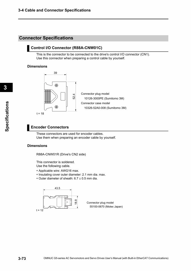
3-4 Cable and Connector Specifications
3
Spec
ifica
tions
Connector Specifications
Control I/O Connector (R88A-CNW01C)This is the connector to be connected to the drive's control I/O connector (CN1).Use this connector when preparing a control cable by yourself.
Dimensions
Encoder ConnectorsThese connectors are used for encoder cables.Use them when preparing an encoder cable by yourself.
Dimensions
R88A-CNW01R (Drive's CN2 side)
This connector is soldered.Use the following cable.
Applicable wire: AWG16 max.Insulating cover outer diameter: 2.1 mm dia. max.Outer diameter of sheath: 6.7 ± 0.5 mm dia.
52.4
39
t = 18
Connector plug model 10126-3000PE (Sumitomo 3M)Connector case model 10326-52A0-008 (Sumitomo 3M)
t = 12
43.5
18.8
Connector plug model 55100-0670 (Molex Japan)
3-73 OMNUC G5-series AC Servomotors and Servo Drives User’s Manual (with Built-in EtherCAT Communications)
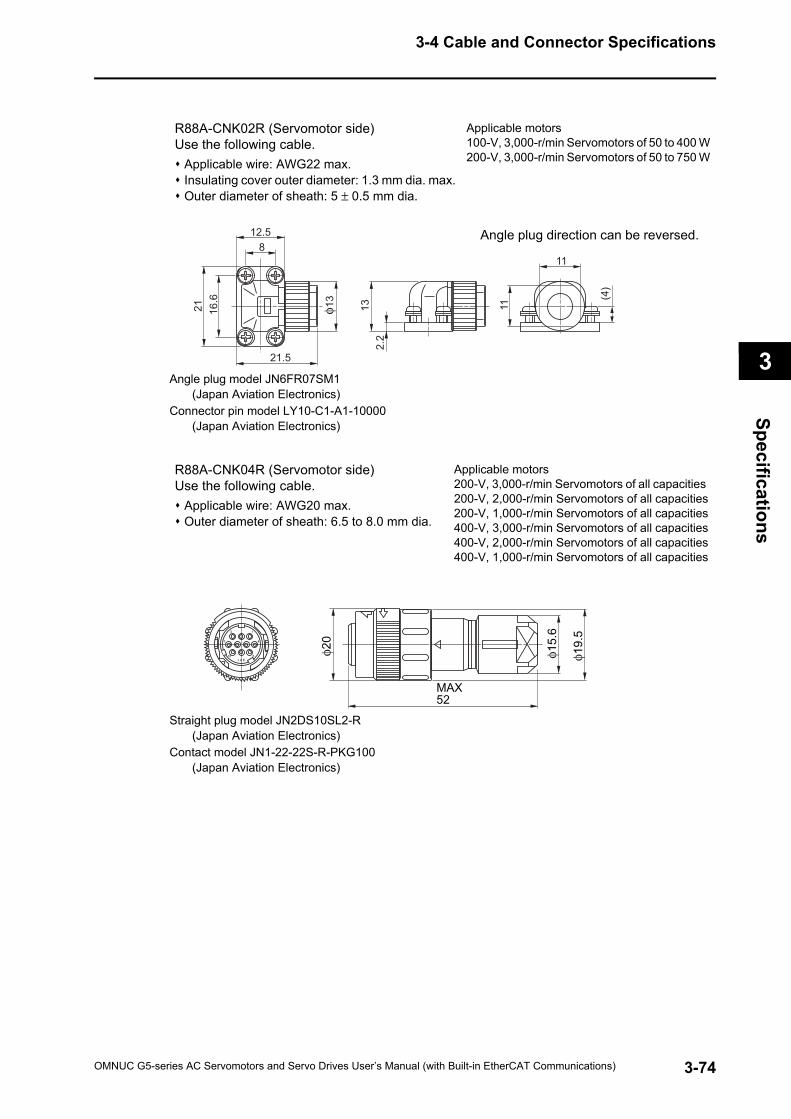
3-4 Cable and Connector Specifications
3
Specifications
Angle plug model JN6FR07SM1 (Japan Aviation Electronics)
Connector pin model LY10-C1-A1-10000 (Japan Aviation Electronics)
Straight plug model JN2DS10SL2-R (Japan Aviation Electronics)
Contact model JN1-22-22S-R-PKG100 (Japan Aviation Electronics)
R88A-CNK02R (Servomotor side)Use the following cable.
Applicable wire: AWG22 max.Insulating cover outer diameter: 1.3 mm dia. max.Outer diameter of sheath: 5 ± 0.5 mm dia.
Applicable motors100-V, 3,000-r/min Servomotors of 50 to 400 W 200-V, 3,000-r/min Servomotors of 50 to 750 W
12.5
21.5
φ13
21 16.6
8
132.
2
11
11
(4)
Angle plug direction can be reversed.
R88A-CNK04R (Servomotor side)Use the following cable.
Applicable wire: AWG20 max.Outer diameter of sheath: 6.5 to 8.0 mm dia.
Applicable motors200-V, 3,000-r/min Servomotors of all capacities 200-V, 2,000-r/min Servomotors of all capacities 200-V, 1,000-r/min Servomotors of all capacities 400-V, 3,000-r/min Servomotors of all capacities 400-V, 2,000-r/min Servomotors of all capacities 400-V, 1,000-r/min Servomotors of all capacities
3 1
47
10J A E
8 φ15.
6
MAX52
φ20
φ19.
5
3-74OMNUC G5-series AC Servomotors and Servo Drives User’s Manual (with Built-in EtherCAT Communications)
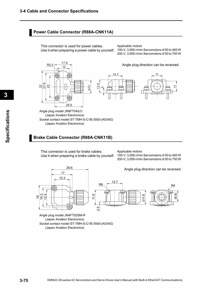
3-4 Cable and Connector Specifications
3
Spec
ifica
tions
Power Cable Connector (R88A-CNK11A)
Angle plug model JN8FT04SJ1 (Japan Aviation Electronics)
Socket contact model ST-TMH-S-C1B-3500-(A534G) (Japan Aviation Electronics)
Brake Cable Connector (R88A-CNK11B)
Angle plug model JN4FT02SM-R (Japan Aviation Electronics)
Socket contact model ST-TMH-S-C1B-3500-(A534G) (Japan Aviation Electronics)
This connector is used for power cables.Use it when preparing a power cable by yourself.
Applicable motors100-V, 3,000-r/min Servomotors of 50 to 400 W 200-V, 3,000-r/min Servomotors of 50 to 750 W
17.6
28.8
φ1332 27.6
22
12R5.5
14.7
13.5
3 11
11
Angle plug direction can be reversed.
This connector is used for brake cables.Use it when preparing a brake cable by yourself.
Applicable motors100-V, 3,000-r/min Servomotors of 50 to 400 W 200-V, 3,000-r/min Servomotors of 50 to 750 W
29.6
12.317
12.5
14.3
19
2.5
11.8
R612.7
φ11.
6
(8.8
)
R4
Angle plug direction can be reversed.
3-75 OMNUC G5-series AC Servomotors and Servo Drives User’s Manual (with Built-in EtherCAT Communications)
3-4 Cable and Connector Specifications
3
Specifications
EtherCAT Communications Cable SpecificationsFor the EtherCAT communications cable, use a cable with double, aluminum tape and braidedshielding of category 5 or higher.
Precautions for Correct Use
The maximum length between nodes is 100 m. However, some cables are specified for lessthan 100 m. Generally speaking, if the conductors are twisted wire rather than solid wire,transmission performance will be lower, and reliable communications may not be possible at100 m. Confirm details with the cable manufacturer.
Reference
If an Ethernet cable of category 5 or higher is used, communications will be possible even ifthe cable is not shielded. However, we recommend a cable with double, aluminum tape andbraided shielding to ensure sufficient noise immunity.
Recommended Connector (Modular Plug)Use a shielded connector of category 5 or higher.
Precautions for Correct Use
When selecting a connector, confirm that it is applicable to the cable that will be used. Confirmthe following items: Conductor size, conductor type (solid wire or twisted wire), number oftwisted pairs (2 or 4), outer diameter, etc.
3-76OMNUC G5-series AC Servomotors and Servo Drives User’s Manual (with Built-in EtherCAT Communications)
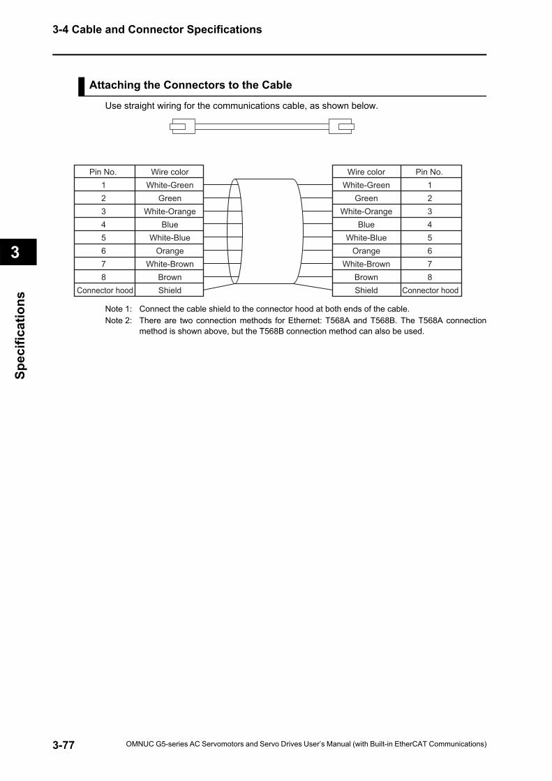
3-4 Cable and Connector Specifications
3
Spec
ifica
tions
Attaching the Connectors to the Cable
Use straight wiring for the communications cable, as shown below.
Note 1: Connect the cable shield to the connector hood at both ends of the cable. Note 2: There are two connection methods for Ethernet: T568A and T568B. The T568A connection
method is shown above, but the T568B connection method can also be used.
12345678
12345678
Wire colorWhite-Green
GreenWhite-Orange
BlueWhite-Blue
OrangeWhite-Brown
BrownShield Connector hood
Pin No. Wire colorWhite-Green
GreenWhite-Orange
BlueWhite-Blue
OrangeWhite-Brown
BrownShieldConnector hood
Pin No.
3-77 OMNUC G5-series AC Servomotors and Servo Drives User’s Manual (with Built-in EtherCAT Communications)
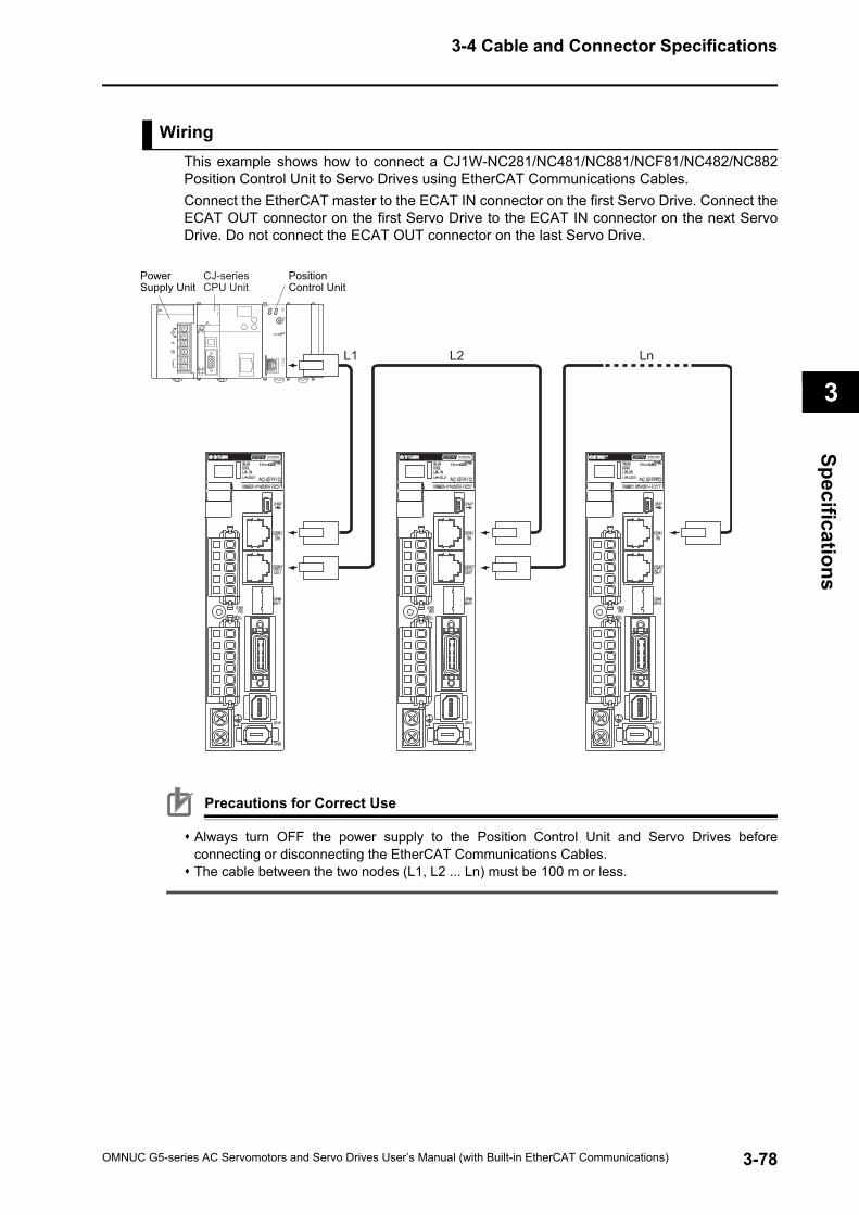
3-4 Cable and Connector Specifications
3
Specifications
WiringThis example shows how to connect a CJ1W-NC281/NC481/NC881/NCF81/NC482/NC882Position Control Unit to Servo Drives using EtherCAT Communications Cables.Connect the EtherCAT master to the ECAT IN connector on the first Servo Drive. Connect theECAT OUT connector on the first Servo Drive to the ECAT IN connector on the next ServoDrive. Do not connect the ECAT OUT connector on the last Servo Drive.
Precautions for Correct Use
Always turn OFF the power supply to the Position Control Unit and Servo Drives beforeconnecting or disconnecting the EtherCAT Communications Cables.The cable between the two nodes (L1, L2 ... Ln) must be 100 m or less.
L1 L2 Ln
CJ-series CPU Unit
Power Supply Unit
Position Control Unit
3-78OMNUC G5-series AC Servomotors and Servo Drives User’s Manual (with Built-in EtherCAT Communications)
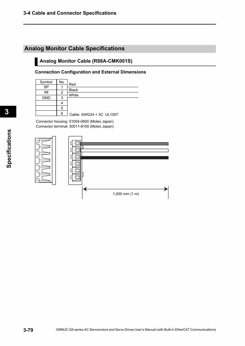
3-4 Cable and Connector Specifications
3
Spec
ifica
tions
Analog Monitor Cable Specifications
Analog Monitor Cable (R88A-CMK001S)
Connection Configuration and External Dimensions
No.12
Symbol
BlackRed
White
Cable: AWG24 × 3C UL1007
3456
Connector housing: 51004-0600 (Molex Japan)Connector terminal: 50011-8100 (Molex Japan)
SPIM
GND
1,000 mm (1 m)
3-79 OMNUC G5-series AC Servomotors and Servo Drives User’s Manual (with Built-in EtherCAT Communications)
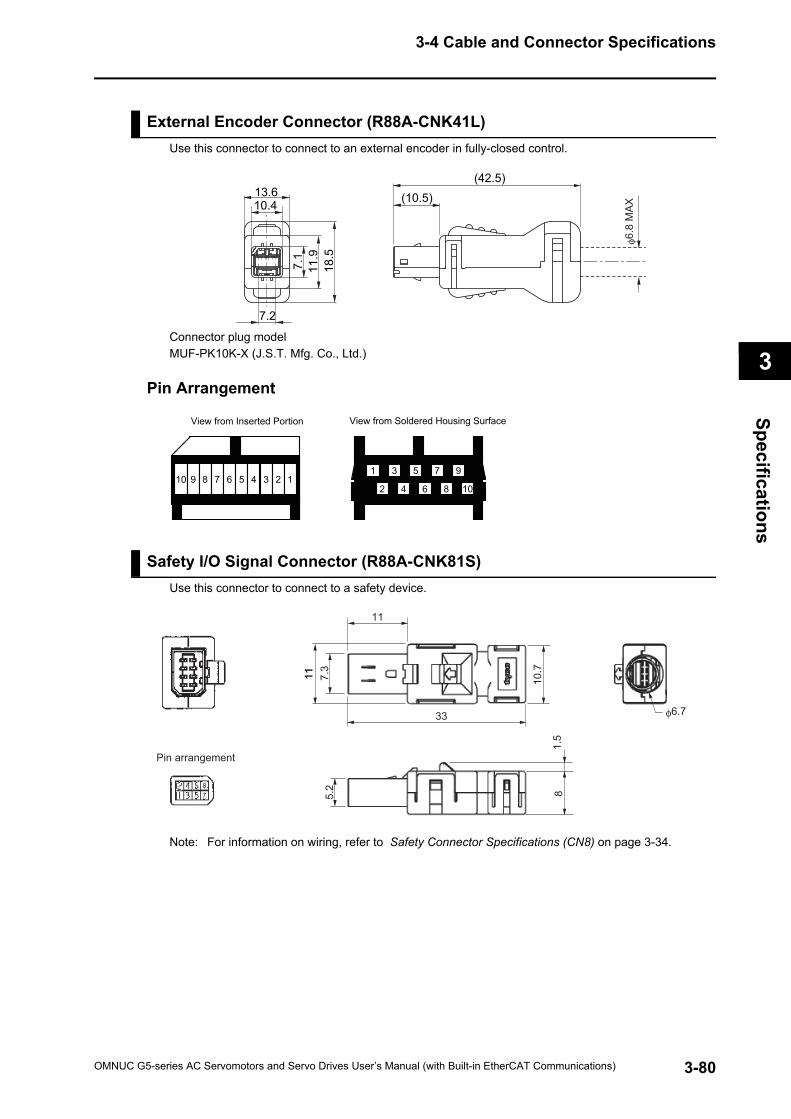
3-4 Cable and Connector Specifications
3
Specifications
External Encoder Connector (R88A-CNK41L)Use this connector to connect to an external encoder in fully-closed control.
Connector plug modelMUF-PK10K-X (J.S.T. Mfg. Co., Ltd.)
Pin Arrangement
Safety I/O Signal Connector (R88A-CNK81S) Use this connector to connect to a safety device.
Note: For information on wiring, refer to Safety Connector Specifications (CN8) on page 3-34.
7.2
13.610.4
7.1
11.9
18.5
(42.5)(10.5)
φ6.8
MA
X
10 9 8 7 6 5 4 3 2 1
View from Inserted Portion View from Soldered Housing Surface
10
9
8
7
6
5
4
3
2
1
7.3
5.2
1111 10.7
81.
5
11
33 φ6.7
Pin arrangement
8
7
3-80OMNUC G5-series AC Servomotors and Servo Drives User’s Manual (with Built-in EtherCAT Communications)
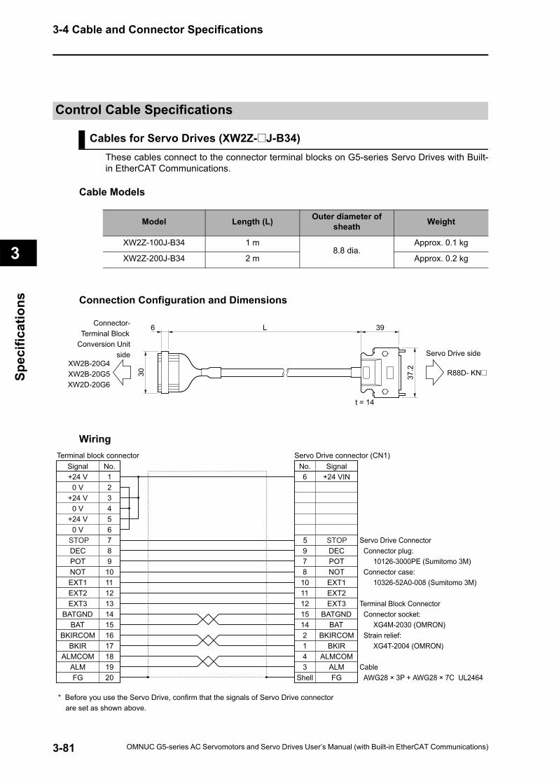
3-4 Cable and Connector Specifications
3
Spec
ifica
tions
Control Cable Specifications
Cables for Servo Drives (XW2Z-@J-B34)These cables connect to the connector terminal blocks on G5-series Servo Drives with Built-in EtherCAT Communications.
Cable Models
Connection Configuration and Dimensions
Wiring
Model Length (L) Outer diameter of sheath Weight
XW2Z-100J-B34 1 m8.8 dia.
Approx. 0.1 kg
XW2Z-200J-B34 2 m Approx. 0.2 kg
37.230
39L6
t = 14
R88D- KN@
Servo Drive side
Connector-Terminal Block
Conversion Unitside
XW2B-20G4XW2B-20G5XW2D-20G6
123456789
1011121314151617181920
No.6 +24 VIN
DEC97 POT8 NOT
10 EXT1EXT211
12
21
EXT3BATGND
1415
BATBKIRCOM
BKIR4
ALM3ALMCOM
FG
No.+24 V
0 V+24 V
0 V+24 V
0 V
DECPOTNOTEXT1EXT2EXT3
BATGNDBAT
BKIRCOMBKIR
ALMALMCOM
FG
STOP STOP5
Terminal block connector
Servo Drive Connector Connector plug: 10126-3000PE (Sumitomo 3M) Connector case: 10326-52A0-008 (Sumitomo 3M)
Terminal Block Connector Connector socket: XG4M-2030 (OMRON) Strain relief: XG4T-2004 (OMRON)
Cable AWG28 × 3P + AWG28 × 7C UL2464
* Before you use the Servo Drive, confirm that the signals of Servo Drive connector are set as shown above.
SignalServo Drive connector (CN1)
Shell
Signal
3-81 OMNUC G5-series AC Servomotors and Servo Drives User’s Manual (with Built-in EtherCAT Communications)
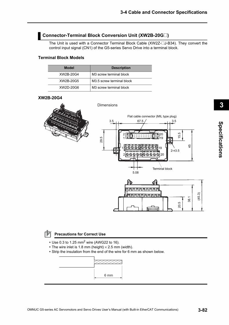
3-4 Cable and Connector Specifications
3
Specifications
Connector-Terminal Block Conversion Unit (XW2B-20G@)The Unit is used with a Connector Terminal Block Cable (XW2Z-@J-B34). They convert thecontrol input signal (CN1) of the G5-series Servo Drive into a terminal block.
Terminal Block Models
XW2B-20G4
Precautions for Correct Use
Use 0.3 to 1.25 mm2 wire (AWG22 to 16).The wire inlet is 1.8 mm (height) × 2.5 mm (width).Strip the insulation from the end of the wire for 6 mm as shown below.
Model Description
XW2B-20G4 M3 screw terminal block
XW2B-20G5 M3.5 screw terminal block
XW2D-20G6 M3 screw terminal block
3.5 3.5
2-φ3.5
67.5
5.08
29.5 15
.520
.5
38.1 (45.
3)
45
2
1
12
20
19
1920
Terminal block
Flat cable connector (MIL type plug)
Dimensions
6 mm
3-82OMNUC G5-series AC Servomotors and Servo Drives User’s Manual (with Built-in EtherCAT Communications)
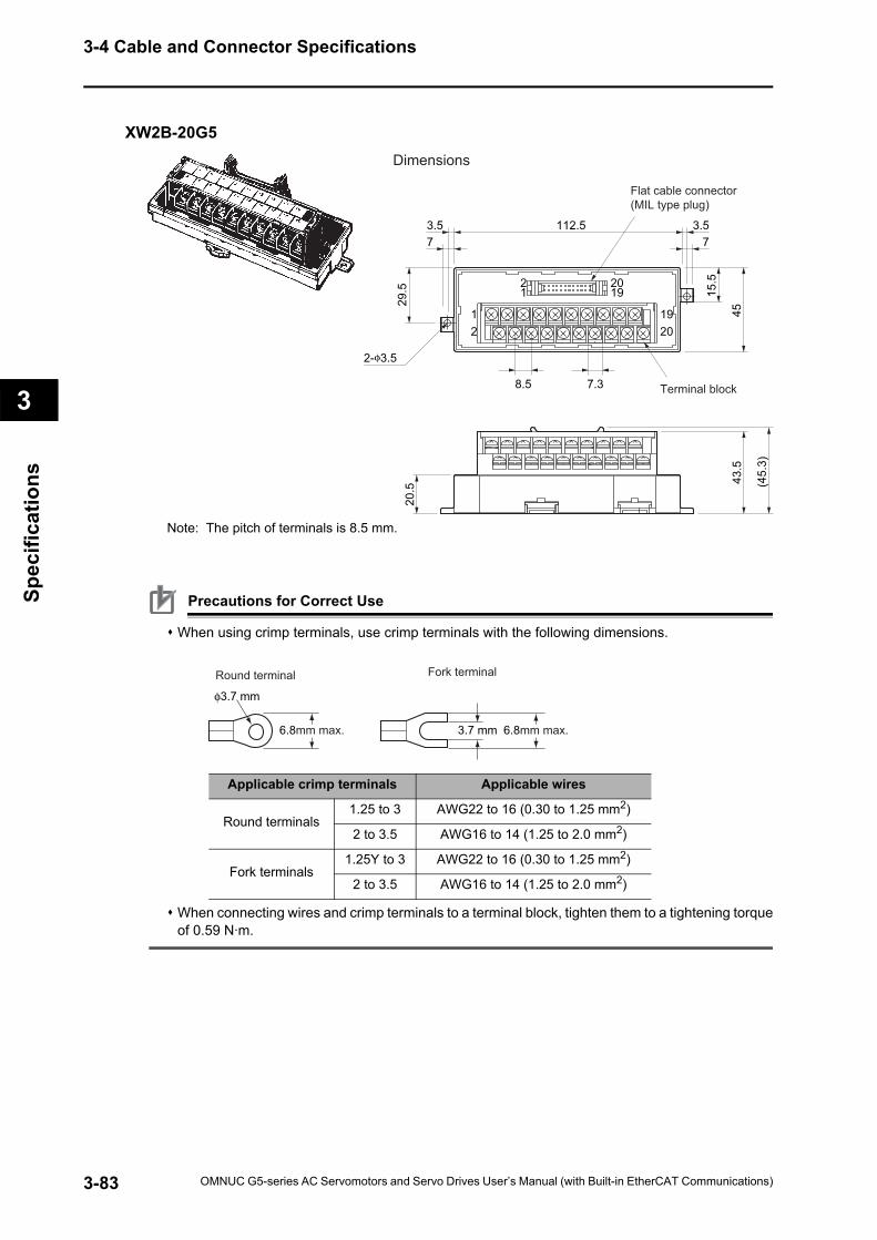
3-4 Cable and Connector Specifications
3
Spec
ifica
tions
XW2B-20G5
Note: The pitch of terminals is 8.5 mm.
Precautions for Correct Use
When using crimp terminals, use crimp terminals with the following dimensions.
When connecting wires and crimp terminals to a terminal block, tighten them to a tightening torqueof 0.59 N·m.
21
12
2019
1920
(45.
3)
43.5
29.5
7
8.5 7.3
3.57
3.5112.5
15.5
45
2-φ3.5
20.5
Dimensions
Flat cable connector (MIL type plug)
Terminal block
φ3.7 mm
3.7 mm6.8mm max. 6.8mm max.
Round terminal Fork terminal
Applicable crimp terminals Applicable wires
Round terminals1.25 to 3 AWG22 to 16 (0.30 to 1.25 mm2)
2 to 3.5 AWG16 to 14 (1.25 to 2.0 mm2)
Fork terminals1.25Y to 3 AWG22 to 16 (0.30 to 1.25 mm2)
2 to 3.5 AWG16 to 14 (1.25 to 2.0 mm2)
3-83 OMNUC G5-series AC Servomotors and Servo Drives User’s Manual (with Built-in EtherCAT Communications)
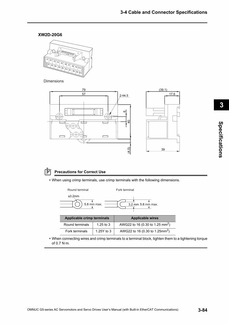
3-4 Cable and Connector Specifications
3
Specifications
XW2D-20G6
Precautions for Correct Use
When using crimp terminals, use crimp terminals with the following dimensions.
When connecting wires and crimp terminals to a terminal block, tighten them to a tightening torqueof 0.7 N·m.
79 (39.1)
39
57 17.6
640
(4.5
)
2-φ4.5
Dimensions
φ3.2mm
3.2 mm
Round terminal Fork terminal
5.8 mm max. 5.8 mm max.
Applicable crimp terminals Applicable wires
Round terminals 1.25 to 3 AWG22 to 16 (0.30 to 1.25 mm2)
Fork terminals 1.25Y to 3 AWG22 to 16 (0.30 to 1.25mm2)
3-84OMNUC G5-series AC Servomotors and Servo Drives User’s Manual (with Built-in EtherCAT Communications)
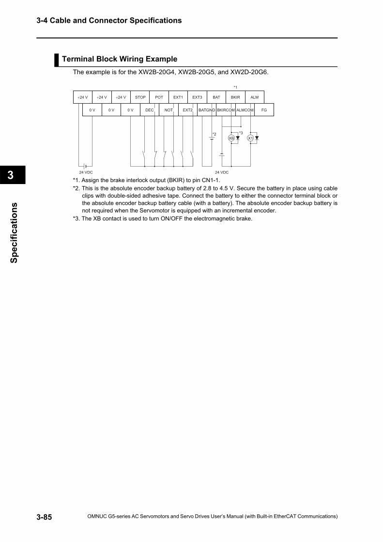
3-4 Cable and Connector Specifications
3
Spec
ifica
tions
Terminal Block Wiring Example The example is for the XW2B-20G4, XW2B-20G5, and XW2D-20G6.
*1. Assign the brake interlock output (BKIR) to pin CN1-1.*2. This is the absolute encoder backup battery of 2.8 to 4.5 V. Secure the battery in place using cable
clips with double-sided adhesive tape. Connect the battery to either the connector terminal block orthe absolute encoder backup battery cable (with a battery). The absolute encoder backup battery isnot required when the Servomotor is equipped with an incremental encoder.
*3. The XB contact is used to turn ON/OFF the electromagnetic brake.
+24 V
0 V
+24 V +24 V POT EXT1 EXT3 BAT BKIR ALM
0 V 0 V DEC EXT2 BATGNDNOT BKIRCOM FG
24 VDC 24 VDC
*3*2
*1
ALMCOM
XB X1
STOP
3-85 OMNUC G5-series AC Servomotors and Servo Drives User’s Manual (with Built-in EtherCAT Communications)
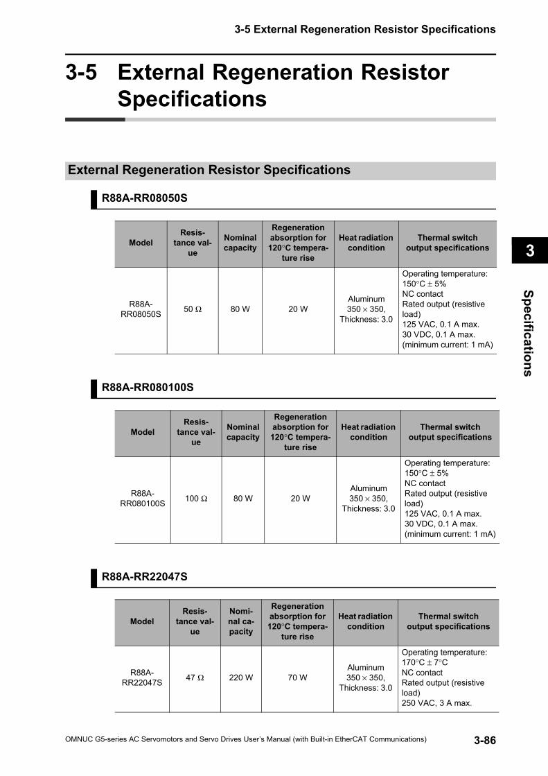
3-5 External Regeneration Resistor Specifications
3
Specifications
3-5 External Regeneration ResistorSpecifications
External Regeneration Resistor Specifications
R88A-RR08050S
R88A-RR080100S
R88A-RR22047S
ModelResis-
tance val-ue
Nominal capacity
Regeneration absorption for 120°C tempera-
ture rise
Heat radiation condition
Thermal switch output specifications
R88A-RR08050S 50 Ω 80 W 20 W
Aluminum 350 × 350,
Thickness: 3.0
Operating temperature: 150°C ± 5% NC contactRated output (resistive load)125 VAC, 0.1 A max.30 VDC, 0.1 A max.(minimum current: 1 mA)
ModelResis-
tance val-ue
Nominal capacity
Regeneration absorption for 120°C tempera-
ture rise
Heat radiation condition
Thermal switch output specifications
R88A-RR080100S 100 Ω 80 W 20 W
Aluminum 350 × 350,
Thickness: 3.0
Operating temperature: 150°C ± 5% NC contactRated output (resistive load)125 VAC, 0.1 A max.30 VDC, 0.1 A max.(minimum current: 1 mA)
ModelResis-
tance val-ue
Nomi-nal ca-pacity
Regeneration absorption for 120°C tempera-
ture rise
Heat radiation condition
Thermal switch output specifications
R88A-RR22047S 47 Ω 220 W 70 W
Aluminum 350 × 350,
Thickness: 3.0
Operating temperature: 170°C ± 7°CNC contactRated output (resistive load)250 VAC, 3 A max.
3-86OMNUC G5-series AC Servomotors and Servo Drives User’s Manual (with Built-in EtherCAT Communications)
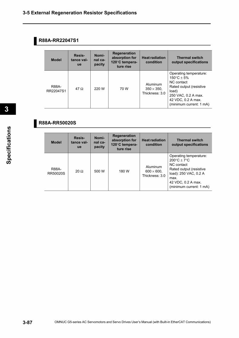
3-5 External Regeneration Resistor Specifications
3
Spec
ifica
tions
R88A-RR22047S1
R88A-RR50020S
ModelResis-
tance val-ue
Nomi-nal ca-pacity
Regeneration absorption for 120°C tempera-
ture rise
Heat radiation condition
Thermal switch output specifications
R88A-RR22047S1 47 Ω 220 W 70 W
Aluminum 350 × 350,
Thickness: 3.0
Operating temperature: 150°C ± 5% NC contactRated output (resistive load)250 VAC, 0.2 A max.42 VDC, 0.2 A max.(minimum current: 1 mA)
ModelResis-
tance val-ue
Nomi-nal ca-pacity
Regeneration absorption for 120°C tempera-
ture rise
Heat radiation condition
Thermal switch output specifications
R88A-RR50020S 20 Ω 500 W 180 W
Aluminum 600 × 600,
Thickness: 3.0
Operating temperature: 200°C ± 7°CNC contactRated output (resistive load): 250 VAC, 0.2 A max.42 VDC, 0.2 A max. (minimum current: 1 mA)
3-87 OMNUC G5-series AC Servomotors and Servo Drives User’s Manual (with Built-in EtherCAT Communications)
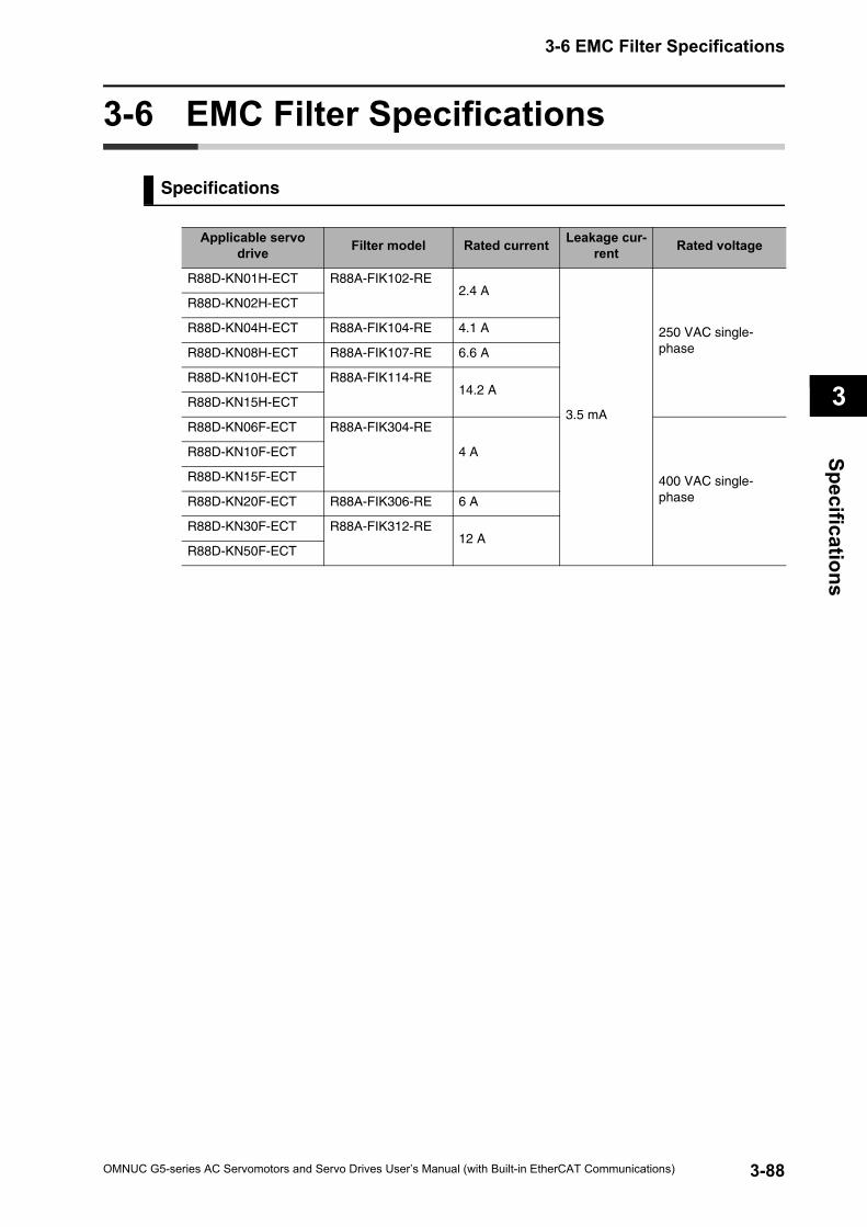
3-6 EMC Filter Specifications
3
Specifications
3-6 EMC Filter Specifications
Specifications
Applicable servo drive Filter model Rated current Leakage cur-
rent Rated voltage
R88D-KN01H-ECT R88A-FIK102-RE2.4 A
3.5 mA
250 VAC single-phase
R88D-KN02H-ECT
R88D-KN04H-ECT R88A-FIK104-RE 4.1 A
R88D-KN08H-ECT R88A-FIK107-RE 6.6 A
R88D-KN10H-ECT R88A-FIK114-RE14.2 A
R88D-KN15H-ECT
R88D-KN06F-ECT R88A-FIK304-RE
4 A
400 VAC single-phase
R88D-KN10F-ECT
R88D-KN15F-ECT
R88D-KN20F-ECT R88A-FIK306-RE 6 A
R88D-KN30F-ECT R88A-FIK312-RE12 A
R88D-KN50F-ECT
3-88OMNUC G5-series AC Servomotors and Servo Drives User’s Manual (with Built-in EtherCAT Communications)
3-6 EMC Filter Specifications
3
Spec
ifica
tions
3-89 OMNUC G5-series AC Servomotors and Servo Drives User’s Manual (with Built-in EtherCAT Communications)
OMNUC G5-series AC Servomotors and Servo Drives User’s Manual (with Built-in EtherCAT Communications)
4
System DesignThis chapter explains the installation conditions, wiring methods (including wiringconforming to EMC Directives), and regenerative energy calculation methods forthe Servo Drive and Servomotor. It also explains the performance of ExternalRegeneration Resistors.
4-1 Installation Conditions .................................................4-14-2 Wiring.............................................................................4-64-3 Wiring Conforming to EMC Directives......................4-304-4 Regenerative Energy Absorption..............................4-49
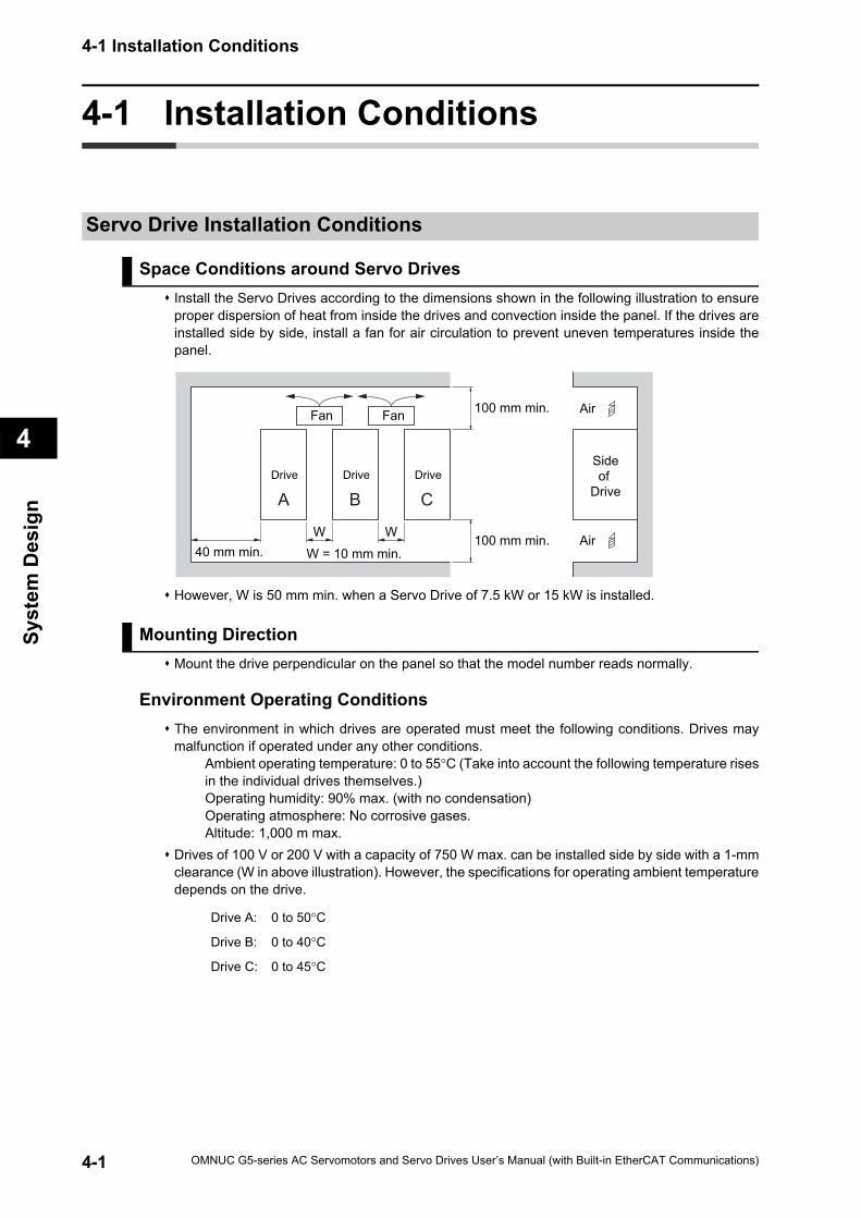
4-1 Installation Conditions
4
Syst
em D
esig
n
4-1 Installation Conditions
Servo Drive Installation Conditions
Space Conditions around Servo DrivesInstall the Servo Drives according to the dimensions shown in the following illustration to ensureproper dispersion of heat from inside the drives and convection inside the panel. If the drives areinstalled side by side, install a fan for air circulation to prevent uneven temperatures inside thepanel.
However, W is 50 mm min. when a Servo Drive of 7.5 kW or 15 kW is installed.
Mounting DirectionMount the drive perpendicular on the panel so that the model number reads normally.
Environment Operating ConditionsThe environment in which drives are operated must meet the following conditions. Drives maymalfunction if operated under any other conditions.
Ambient operating temperature: 0 to 55°C (Take into account the following temperature risesin the individual drives themselves.)Operating humidity: 90% max. (with no condensation)Operating atmosphere: No corrosive gases.Altitude: 1,000 m max.
Drives of 100 V or 200 V with a capacity of 750 W max. can be installed side by side with a 1-mmclearance (W in above illustration). However, the specifications for operating ambient temperaturedepends on the drive.
Drive A: 0 to 50°C
Drive B: 0 to 40°C
Drive C: 0 to 45°C
WW
Sideof
DriveA B CDrive Drive Drive
40 mm min.100 mm min.
Air
Air
Fan Fan
W = 10 mm min.
100 mm min.
4-1 OMNUC G5-series AC Servomotors and Servo Drives User’s Manual (with Built-in EtherCAT Communications)
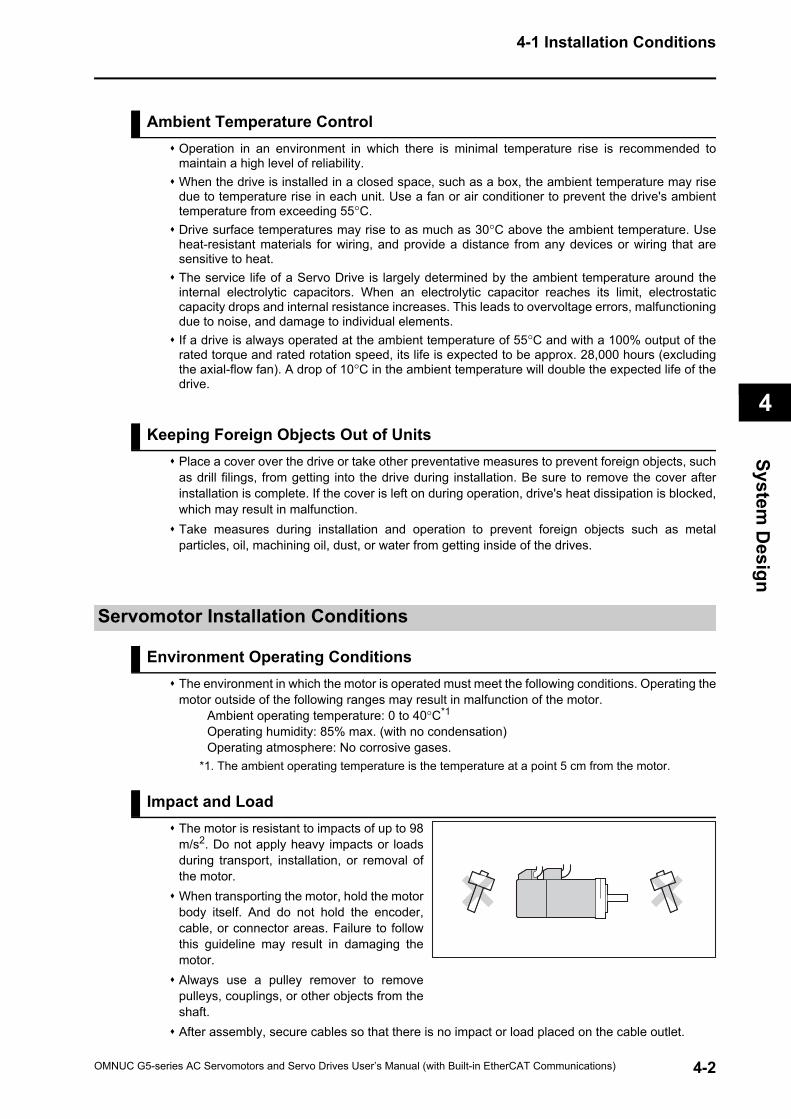
4-1 Installation Conditions
4
System D
esign
Ambient Temperature ControlOperation in an environment in which there is minimal temperature rise is recommended tomaintain a high level of reliability.When the drive is installed in a closed space, such as a box, the ambient temperature may risedue to temperature rise in each unit. Use a fan or air conditioner to prevent the drive's ambienttemperature from exceeding 55°C.Drive surface temperatures may rise to as much as 30°C above the ambient temperature. Useheat-resistant materials for wiring, and provide a distance from any devices or wiring that aresensitive to heat.The service life of a Servo Drive is largely determined by the ambient temperature around theinternal electrolytic capacitors. When an electrolytic capacitor reaches its limit, electrostaticcapacity drops and internal resistance increases. This leads to overvoltage errors, malfunctioningdue to noise, and damage to individual elements.If a drive is always operated at the ambient temperature of 55°C and with a 100% output of therated torque and rated rotation speed, its life is expected to be approx. 28,000 hours (excludingthe axial-flow fan). A drop of 10°C in the ambient temperature will double the expected life of thedrive.
Keeping Foreign Objects Out of UnitsPlace a cover over the drive or take other preventative measures to prevent foreign objects, suchas drill filings, from getting into the drive during installation. Be sure to remove the cover afterinstallation is complete. If the cover is left on during operation, drive's heat dissipation is blocked,which may result in malfunction.Take measures during installation and operation to prevent foreign objects such as metalparticles, oil, machining oil, dust, or water from getting inside of the drives.
Servomotor Installation Conditions
Environment Operating ConditionsThe environment in which the motor is operated must meet the following conditions. Operating themotor outside of the following ranges may result in malfunction of the motor.
Ambient operating temperature: 0 to 40°C*1
Operating humidity: 85% max. (with no condensation)Operating atmosphere: No corrosive gases.
*1. The ambient operating temperature is the temperature at a point 5 cm from the motor.
Impact and LoadThe motor is resistant to impacts of up to 98m/s2. Do not apply heavy impacts or loadsduring transport, installation, or removal ofthe motor.When transporting the motor, hold the motorbody itself. And do not hold the encoder,cable, or connector areas. Failure to followthis guideline may result in damaging themotor.Always use a pulley remover to removepulleys, couplings, or other objects from theshaft.After assembly, secure cables so that there is no impact or load placed on the cable outlet.
4-2OMNUC G5-series AC Servomotors and Servo Drives User’s Manual (with Built-in EtherCAT Communications)
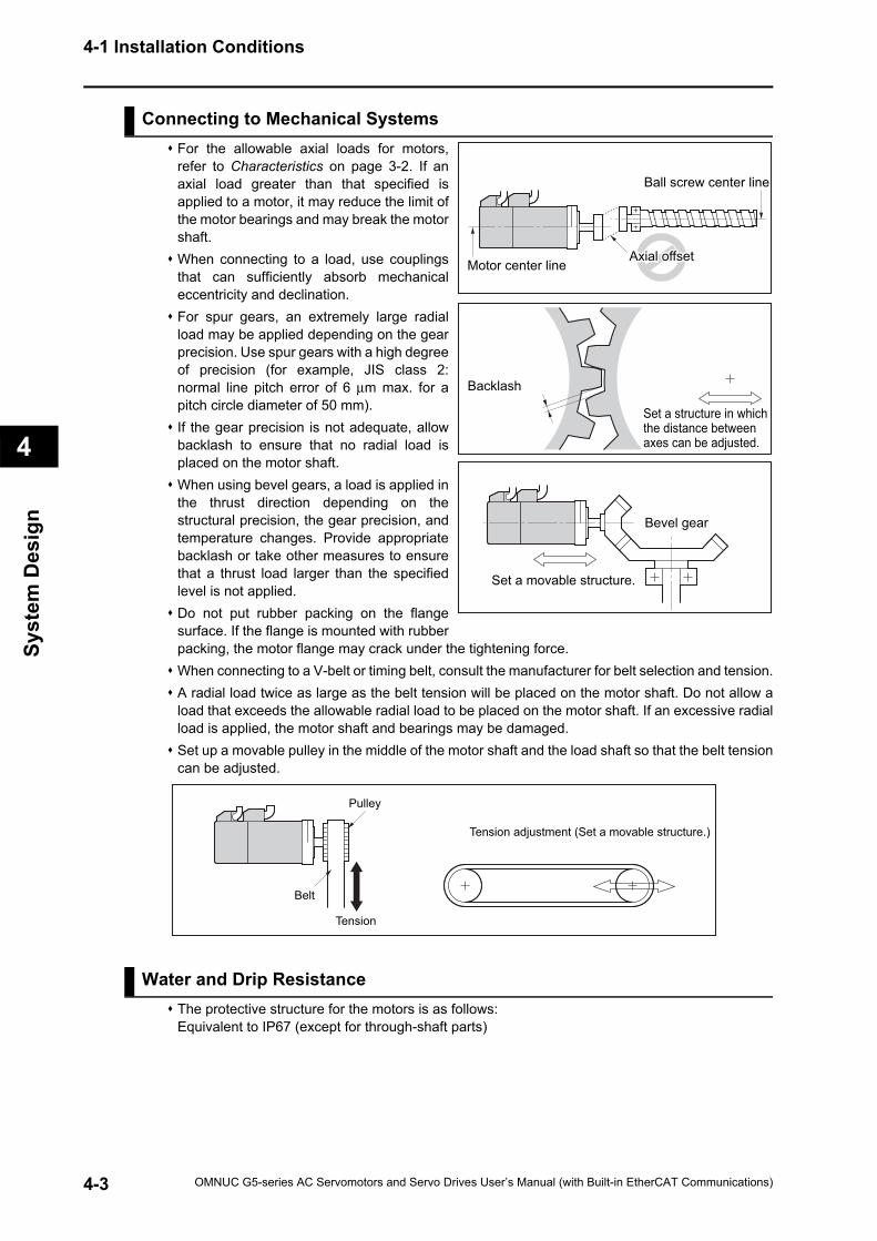
4-1 Installation Conditions
4
Syst
em D
esig
n
Connecting to Mechanical SystemsFor the allowable axial loads for motors,refer to Characteristics on page 3-2. If anaxial load greater than that specified isapplied to a motor, it may reduce the limit ofthe motor bearings and may break the motorshaft.When connecting to a load, use couplingsthat can sufficiently absorb mechanicaleccentricity and declination.For spur gears, an extremely large radialload may be applied depending on the gearprecision. Use spur gears with a high degreeof precision (for example, JIS class 2:normal line pitch error of 6 µm max. for apitch circle diameter of 50 mm).If the gear precision is not adequate, allowbacklash to ensure that no radial load isplaced on the motor shaft.When using bevel gears, a load is applied inthe thrust direction depending on thestructural precision, the gear precision, andtemperature changes. Provide appropriatebacklash or take other measures to ensurethat a thrust load larger than the specifiedlevel is not applied.Do not put rubber packing on the flangesurface. If the flange is mounted with rubberpacking, the motor flange may crack under the tightening force.When connecting to a V-belt or timing belt, consult the manufacturer for belt selection and tension.A radial load twice as large as the belt tension will be placed on the motor shaft. Do not allow aload that exceeds the allowable radial load to be placed on the motor shaft. If an excessive radialload is applied, the motor shaft and bearings may be damaged.Set up a movable pulley in the middle of the motor shaft and the load shaft so that the belt tensioncan be adjusted.
Water and Drip ResistanceThe protective structure for the motors is as follows:Equivalent to IP67 (except for through-shaft parts)
Set a movable structure.
Bevel gear
Set a structure in whichthe distance betweenaxes can be adjusted.
Backlash
Motor center line
Ball screw center line
Axial offsetAxial offsetAxial offset
Pulley
Belt
Tension
Tension adjustment (Set a movable structure.)
4-3 OMNUC G5-series AC Servomotors and Servo Drives User’s Manual (with Built-in EtherCAT Communications)
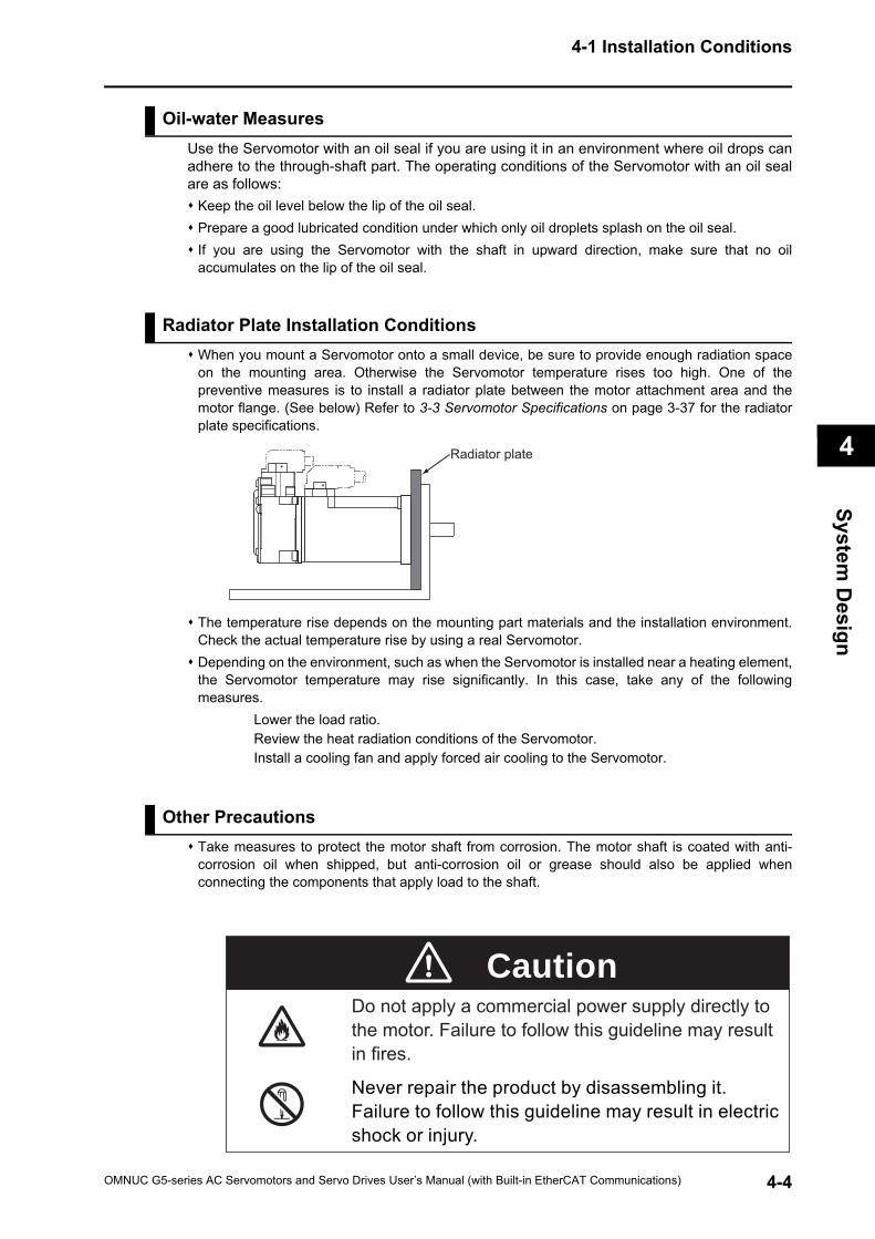
4-1 Installation Conditions
4
System D
esign
Oil-water MeasuresUse the Servomotor with an oil seal if you are using it in an environment where oil drops canadhere to the through-shaft part. The operating conditions of the Servomotor with an oil sealare as follows:
Keep the oil level below the lip of the oil seal.Prepare a good lubricated condition under which only oil droplets splash on the oil seal.If you are using the Servomotor with the shaft in upward direction, make sure that no oilaccumulates on the lip of the oil seal.
Radiator Plate Installation ConditionsWhen you mount a Servomotor onto a small device, be sure to provide enough radiation spaceon the mounting area. Otherwise the Servomotor temperature rises too high. One of thepreventive measures is to install a radiator plate between the motor attachment area and themotor flange. (See below) Refer to 3-3 Servomotor Specifications on page 3-37 for the radiatorplate specifications.
The temperature rise depends on the mounting part materials and the installation environment.Check the actual temperature rise by using a real Servomotor.Depending on the environment, such as when the Servomotor is installed near a heating element,the Servomotor temperature may rise significantly. In this case, take any of the followingmeasures.
Lower the load ratio. Review the heat radiation conditions of the Servomotor. Install a cooling fan and apply forced air cooling to the Servomotor.
Other PrecautionsTake measures to protect the motor shaft from corrosion. The motor shaft is coated with anti-corrosion oil when shipped, but anti-corrosion oil or grease should also be applied whenconnecting the components that apply load to the shaft.
Radiator plate
CautionDo not apply a commercial power supply directly to the motor. Failure to follow this guideline may result in fires.
Never repair the product by disassembling it. Failure to follow this guideline may result in electric shock or injury.
4-4OMNUC G5-series AC Servomotors and Servo Drives User’s Manual (with Built-in EtherCAT Communications)
4-1 Installation Conditions
4
Syst
em D
esig
n
Decelerator Installation Conditions
Using Another Company's Decelerator (Reference)If the system configuration requires another company's decelerator to be used in combinationwith an OMNUC G5-series Servomotor, select the decelerator so that the loads on the motorshaft (i.e., both the radial and thrust loads) are within the allowable ranges. (Refer toCharacteristics on page 3-2 for details on the allowable loads for the motors.)Also, select the decelerator so that the allowable input rotation speed and allowable inputtorque of the decelerator are not exceeded.
4-5 OMNUC G5-series AC Servomotors and Servo Drives User’s Manual (with Built-in EtherCAT Communications)
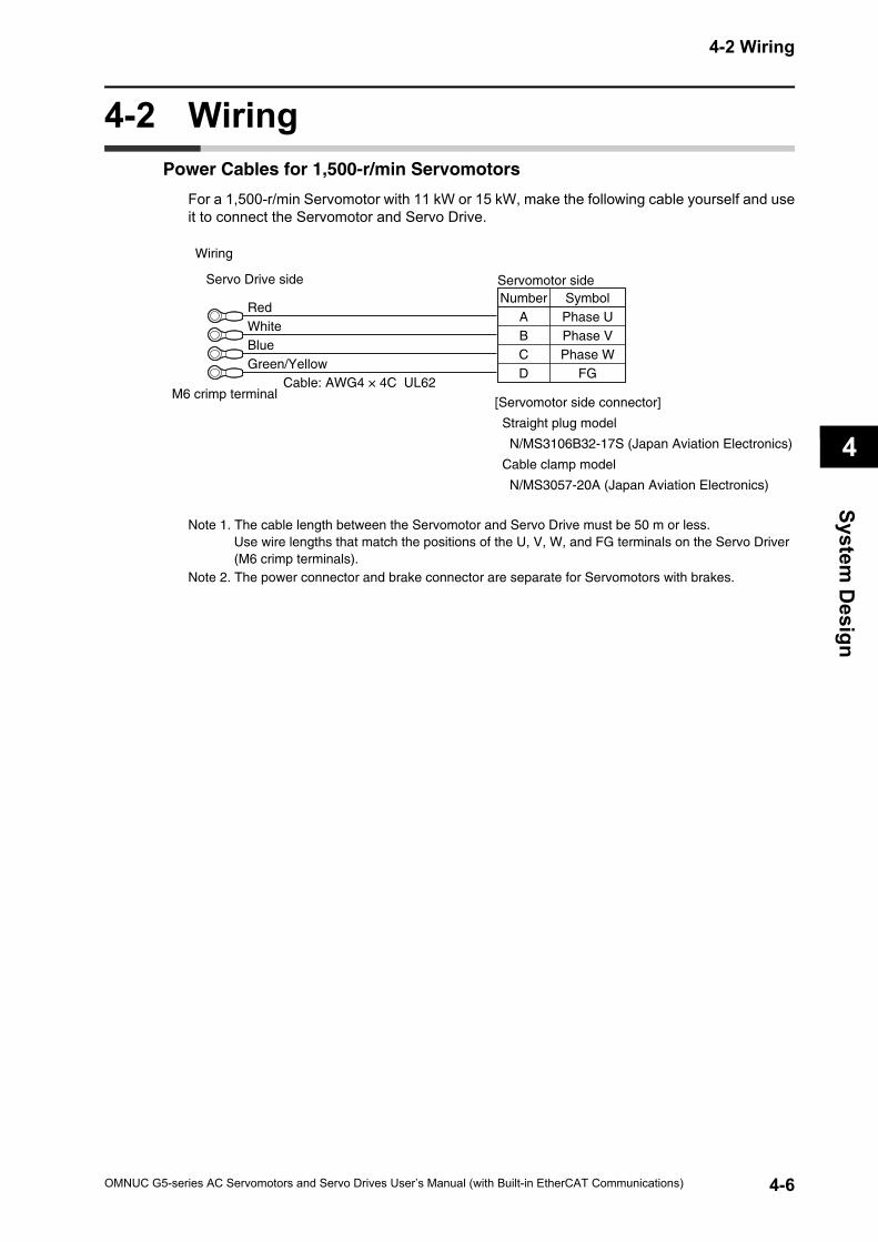
4-2 Wiring
4
System D
esign
4-2 WiringPower Cables for 1,500-r/min Servomotors
For a 1,500-r/min Servomotor with 11 kW or 15 kW, make the following cable yourself and useit to connect the Servomotor and Servo Drive.
Note 1. The cable length between the Servomotor and Servo Drive must be 50 m or less. Use wire lengths that match the positions of the U, V, W, and FG terminals on the Servo Driver (M6 crimp terminals).
Note 2. The power connector and brake connector are separate for Servomotors with brakes.
Cable: AWG4 × 4C UL62
Wiring
Servo Drive side
RedWhiteBlueGreen/Yellow
M6 crimp terminal
NumberABCD
Phase UPhase VPhase W
FG
SymbolServomotor side
[Servomotor side connector]
Straight plug model
N/MS3106B32-17S (Japan Aviation Electronics)
Cable clamp model
N/MS3057-20A (Japan Aviation Electronics)
4-6OMNUC G5-series AC Servomotors and Servo Drives User’s Manual (with Built-in EtherCAT Communications)
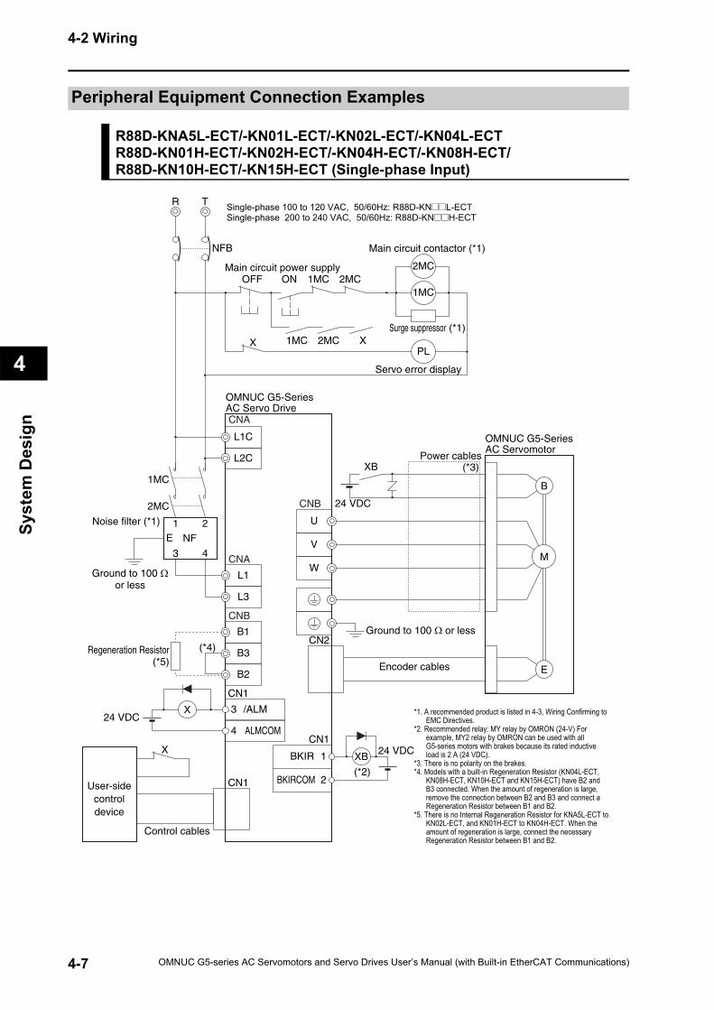
4-2 Wiring
4
Syst
em D
esig
n
Peripheral Equipment Connection Examples
R88D-KNA5L-ECT/-KN01L-ECT/-KN02L-ECT/-KN04L-ECTR88D-KN01H-ECT/-KN02H-ECT/-KN04H-ECT/-KN08H-ECT/R88D-KN10H-ECT/-KN15H-ECT (Single-phase Input)
Single-phase 100 to 120 VAC, 50/60Hz: R88D-KN@@L-ECTSingle-phase 200 to 240 VAC, 50/60Hz: R88D-KN@@H-ECT
*1. A recommended product is listed in 4-3, Wiring Confirming to EMC Directives.
*2. Recommended relay: MY relay by OMRON (24-V) For example, MY2 relay by OMRON can be used with all G5-series motors with brakes because its rated inductive load is 2 A (24 VDC).
*3. There is no polarity on the brakes.*4. Models with a built-in Regeneration Resistor (KN04L-ECT,
KN08H-ECT, KN10H-ECT and KN15H-ECT) have B2 and B3 connected. When the amount of regeneration is large, remove the connection between B2 and B3 and connect a Regeneration Resistor between B1 and B2.
*5. There is no Internal Regeneration Resistor for KNA5L-ECT to KN02L-ECT, and KN01H-ECT to KN04H-ECT. When the amount of regeneration is large, connect the necessary Regeneration Resistor between B1 and B2.
R T
NFB
Noise filter (*1) 1 2
3 4
E NF
Ground to 100 Ωor less
Main circuit contactor (*1)
1MC
PL
Surge suppressor (*1)
Servo error display
L1C
L2C
L1
L3
OMNUC G5-SeriesAC Servo Drive
2MC
ALMCOM
/ALM3
4
User-sidecontroldevice
CN1
X24 VDC
1
2
BKIR
BKIRCOM
XB24 VDC
Control cables
OMNUC G5-SeriesAC Servomotor
W
V
U
B
E
M
CN2Ground to 100 Ω or less
Encoder cables
Power cables
24 VDC
XB (*3)
(*2)
CN1
CN1
B1
B3
B2
(*4)Regeneration Resistor(*5)
CNB
CNB
CNA
CNA
OFF
X
ON
1MC X
X
Main circuit power supply
2MC
1MC 2MC2MC
1MC
4-7 OMNUC G5-series AC Servomotors and Servo Drives User’s Manual (with Built-in EtherCAT Communications)
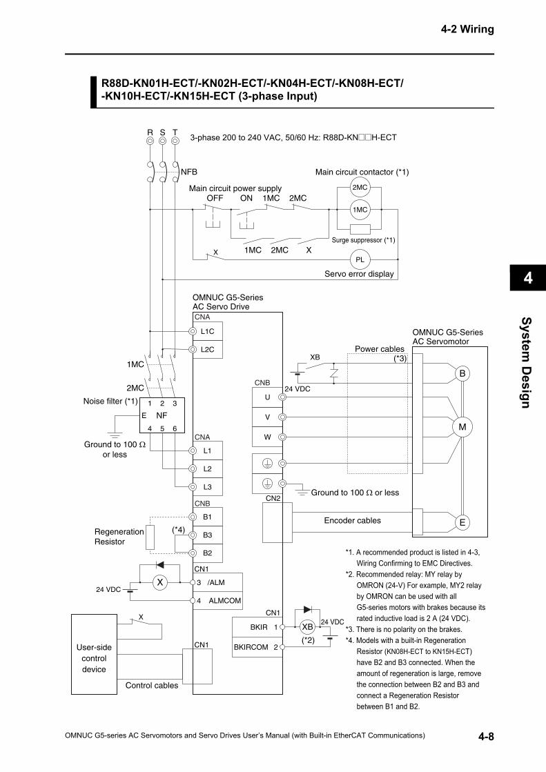
4-2 Wiring
4
System D
esign
R88D-KN01H-ECT/-KN02H-ECT/-KN04H-ECT/-KN08H-ECT/-KN10H-ECT/-KN15H-ECT (3-phase Input)
3-phase 200 to 240 VAC, 50/60 Hz: R88D-KN@@H-ECT
*1. A recommended product is listed in 4-3, Wiring Confirming to EMC Directives.
*2. Recommended relay: MY relay by OMRON (24-V) For example, MY2 relay by OMRON can be used with all G5-series motors with brakes because its rated inductive load is 2 A (24 VDC).
*3. There is no polarity on the brakes.*4. Models with a built-in Regeneration
Resistor (KN08H-ECT to KN15H-ECT) have B2 and B3 connected. When the amount of regeneration is large, remove the connection between B2 and B3 and connect a Regeneration Resistor between B1 and B2.
R T
NFB
S
Noise filter (*1) 1 2 3
4 5 6
E NF
Ground to 100 Ωor less
Main circuit contactor (*1)
PL
Servo error display
L1C
L2C
L1
L2
L3
OMNUC G5-SeriesAC Servo Drive
ALMCOM
/ALM3
4
User-sidecontroldevice
CN1
X24 VDC
1
2
BKIR
BKIRCOM
XB24 VDC
Control cables
OMNUC G5-SeriesAC Servomotor
W
V
U
B
E
M
CN2
Encoder cables
Power cables
24 VDC
(*3)
(*2)
CN1
CN1
B1
B3
B2
(*4)RegenerationResistor
CNB
CNB
CNA
CNA
Ground to 100 Ω or less
X
XB
2MC
X
1MC
Surge suppressor (*1)
OFF ON
1MC X
Main circuit power supply
2MC
1MC 2MC2MC
1MC
4-8OMNUC G5-series AC Servomotors and Servo Drives User’s Manual (with Built-in EtherCAT Communications)

4-2 Wiring
4
Syst
em D
esig
n
R88D-KN20H-ECT
R T
NFB
S
Noise filter (*1) 1 2 3
4 5 6
E NF
Ground to 100 Ωor less
3-phase 200 to 230 VAC, 50/60 Hz: R88D-KN@@H-ECT
Main circuit contactor (*1)
PL
Servo alarm display
L1C
L2C
L1
L2
L3
OMNUC G5-seriesAC Servo Drive
ALMCOM
/ALM37
36
User-sidecontroldevice
CN1
X24 VDC
11
10
BKIR
BKIRCOM
XB 24 VDC
Control cables
OMNUC G5-seriesAC Servomotor
W
V
U
B
E
M
CN2
Encoder cables
Power cables
24 VDC
(*2)
CN1
CN1
*1. Recommended products are listed in 4-3, Wiring Conforming to EMC Directives.
*2. Recommended relay: MY relay by OMRON (24-V) For example, MY2 relay by OMRON can be used with all G5-series motors with brakes because its rated induction load is 2 A (24 VDC).
*3. There is no polarity on the brakes.*4. The Regeneration Resistor built-in type
(KN20H-ECT) shorts B2 and B3. When the amount of regeneration is large, remove the connection between B2 and B3 and connect the Regeneration Resistor between B1 and B2.
B1
B3
B2
(*4)RegenerationResistor
CNB
CNC
CNA
CNA
Ground to 100 Ω or less
X
XB
2MC
X
1MC
Surge suppressor (*1)
OFF ON
1MC X
Main circuit power supply
2MC
1MC 2MC2MC
1MC(*3)
4-9 OMNUC G5-series AC Servomotors and Servo Drives User’s Manual (with Built-in EtherCAT Communications)
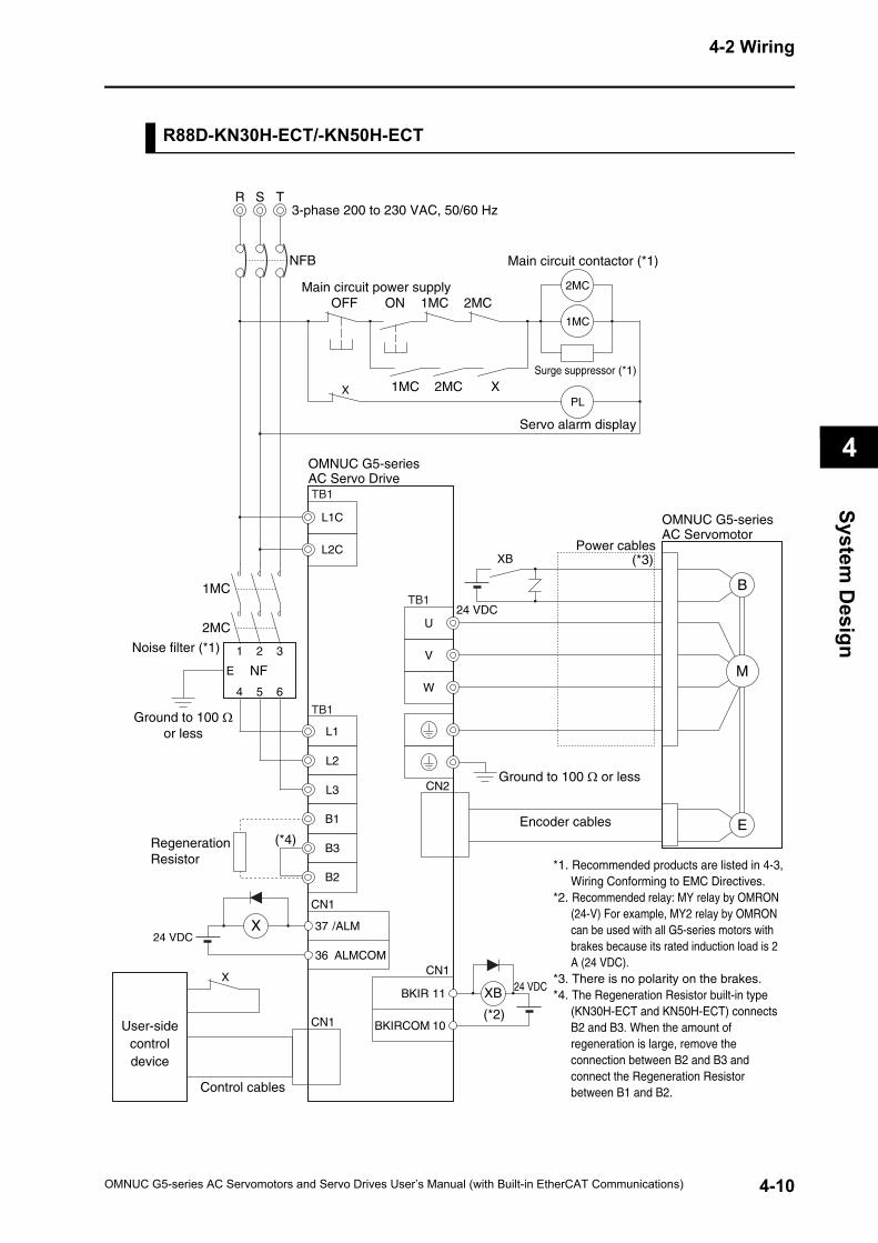
4-2 Wiring
4
System D
esign
R88D-KN30H-ECT/-KN50H-ECT
R T
NFB
S
Noise filter (*1) 1 2 3
4 5 6
E NF
Ground to 100 Ωor less
3-phase 200 to 230 VAC, 50/60 Hz
PL
Servo alarm display
L1C
L2C
L1
L2
L3
OMNUC G5-seriesAC Servo Drive
ALMCOM
/ALM37
36
User-sidecontroldevice
CN1
X24 VDC
11
10
BKIR
BKIRCOM
XB 24 VDC
Control cables
OMNUC G5-seriesAC Servomotor
W
V
U
B
E
M
CN2
Encoder cables
Power cables
24 VDC
(*2)
CN1
CN1
*1. Recommended products are listed in 4-3, Wiring Conforming to EMC Directives.
*2. Recommended relay: MY relay by OMRON (24-V) For example, MY2 relay by OMRON can be used with all G5-series motors with brakes because its rated induction load is 2 A (24 VDC).
*3. There is no polarity on the brakes.*4. The Regeneration Resistor built-in type
(KN30H-ECT and KN50H-ECT) connects B2 and B3. When the amount of regeneration is large, remove the connection between B2 and B3 and connect the Regeneration Resistor between B1 and B2.
B1
B3
B2
(*4)RegenerationResistor
TB1
TB1
TB1
Ground to 100 Ω or less
X
XB
2MC
X
Main circuit contactor (*1)
1MC
Surge suppressor (*1)
OFF ON
1MC X
Main circuit power supply
2MC
1MC 2MC2MC
1MC
(*3)
4-10OMNUC G5-series AC Servomotors and Servo Drives User’s Manual (with Built-in EtherCAT Communications)
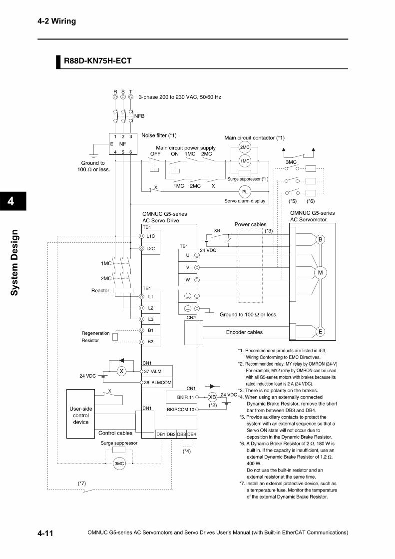
4-2 Wiring
4
Syst
em D
esig
n
R88D-KN75H-ECT
R T
NFB
S
1 2 3
4 5 6
E NF
PL
L1C
L2C
L1
L2
L3
ALMCOM
/ALM37
36
CN1
X
11
10
BKIR
BKIRCOM
XB
W
V
U
B
E
M
CN2
(*3)
(*2)
CN1
CN1
B1
B2
Reactor
TB1
TB1
TB1
X
XB
2MC
X
1MC
OFF ON
1MC X2MC
1MC 2MC2MC
1MC
DB1 DB2 DB3 DB4
(*4)
3-phase 200 to 230 VAC, 50/60 Hz
Noise filter (*1) Main circuit contactor (*1)
Main circuit power supply
Surge suppressor (*1)
Servo alarm display
OMNUC G5-seriesAC Servo Drive
Power cables
OMNUC G5-seriesAC Servomotor
Encoder cablesRegeneration
Resistor
24 VDC
24 VDC
24 VDC
User-sidecontroldevice
Control cables
Surge suppressor
*1. Recommended products are listed in 4-3, Wiring Conforming to EMC Directives.
*2. Recommended relay: MY relay by OMRON (24-V) For example, MY2 relay by OMRON can be used with all G5-series motors with brakes because its rated induction load is 2 A (24 VDC).
*3. There is no polarity on the brakes.*4. When using an externally connected
Dynamic Brake Resistor, remove the short bar from between DB3 and DB4.
*5. Provide auxiliary contacts to protect the system with an external sequence so that a Servo ON state will not occur due to deposition in the Dynamic Brake Resistor.
*6. A Dynamic Brake Resistor of 2 Ω, 180 W is built in. If the capacity is insufficient, use an external Dynamic Brake Resistor of 1.2 Ω, 400 W.Do not use the built-in resistor and an external resistor at the same time.
*7. Install an external protective device, such as a temperature fuse. Monitor the temperature of the external Dynamic Brake Resistor.
Ground to 100 Ω or less.
Ground to 100 Ω or less.
3MC
3MC
(*5) (*6)
(*7)
4-11 OMNUC G5-series AC Servomotors and Servo Drives User’s Manual (with Built-in EtherCAT Communications)
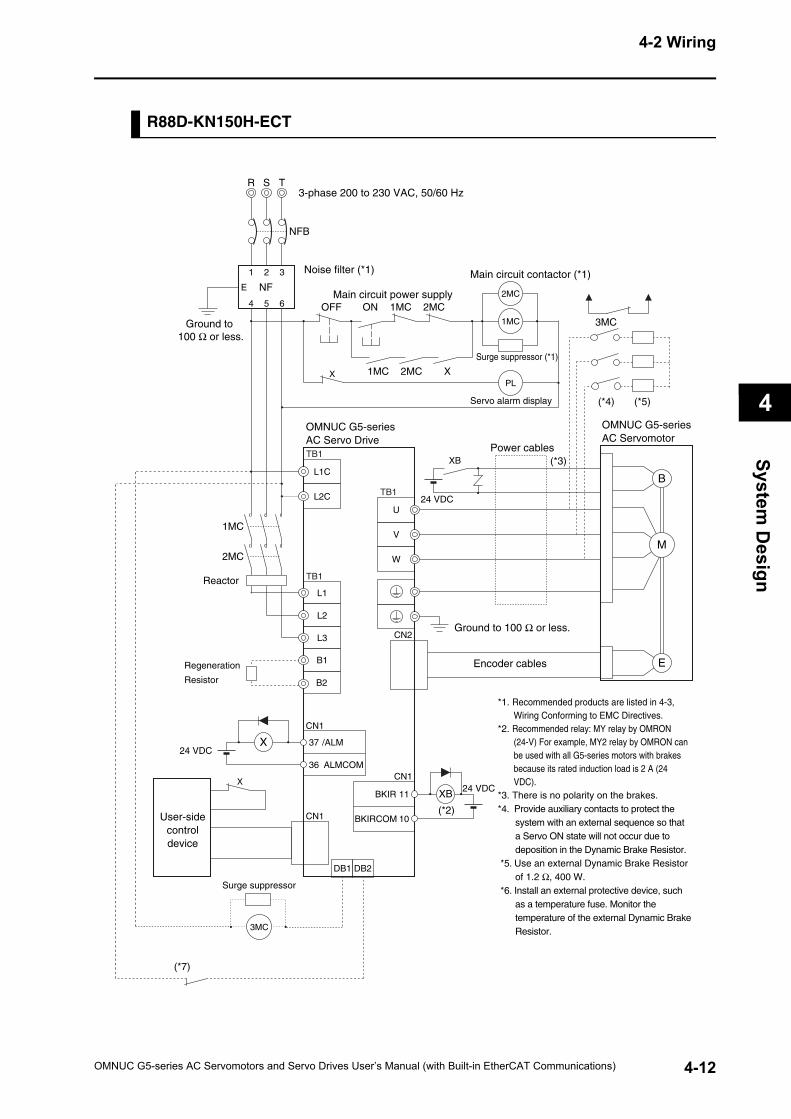
4-2 Wiring
4
System D
esign
R88D-KN150H-ECT
R T
NFB
S
1 2 3
4 5 6
E NF
PL
L1C
L2C
L1
L2
L3
ALMCOM
/ALM37
36
CN1
X
11
10
BKIR
BKIRCOM
XB
W
V
U
B
E
M
CN2
(*3)
(*2)
CN1
CN1
B1
B2
Reactor
TB1
TB1
TB1
X
XB
2MC
X
1MC
OFF ON
1MC X2MC
1MC 2MC2MC
1MC
DB1 DB2
3-phase 200 to 230 VAC, 50/60 Hz
Noise filter (*1) Main circuit contactor (*1)
Main circuit power supply
Surge suppressor (*1)
Servo alarm display
OMNUC G5-seriesAC Servo Drive
Power cables
OMNUC G5-seriesAC Servomotor
Encoder cablesRegeneration
Resistor
User-sidecontroldevice
Surge suppressor
24 VDC
24 VDC
24 VDC
*1. Recommended products are listed in 4-3, Wiring Conforming to EMC Directives.
*2. Recommended relay: MY relay by OMRON (24-V) For example, MY2 relay by OMRON can be used with all G5-series motors with brakes because its rated induction load is 2 A (24 VDC).
*3. There is no polarity on the brakes.*4. Provide auxiliary contacts to protect the
system with an external sequence so that a Servo ON state will not occur due to deposition in the Dynamic Brake Resistor.
*5. Use an external Dynamic Brake Resistor of 1.2 Ω, 400 W.
*6. Install an external protective device, such as a temperature fuse. Monitor the temperature of the external Dynamic Brake Resistor.
Ground to 100 Ω or less.
Ground to 100 Ω or less.
3MC
(*4) (*5)
(*7)
3MC
4-12OMNUC G5-series AC Servomotors and Servo Drives User’s Manual (with Built-in EtherCAT Communications)
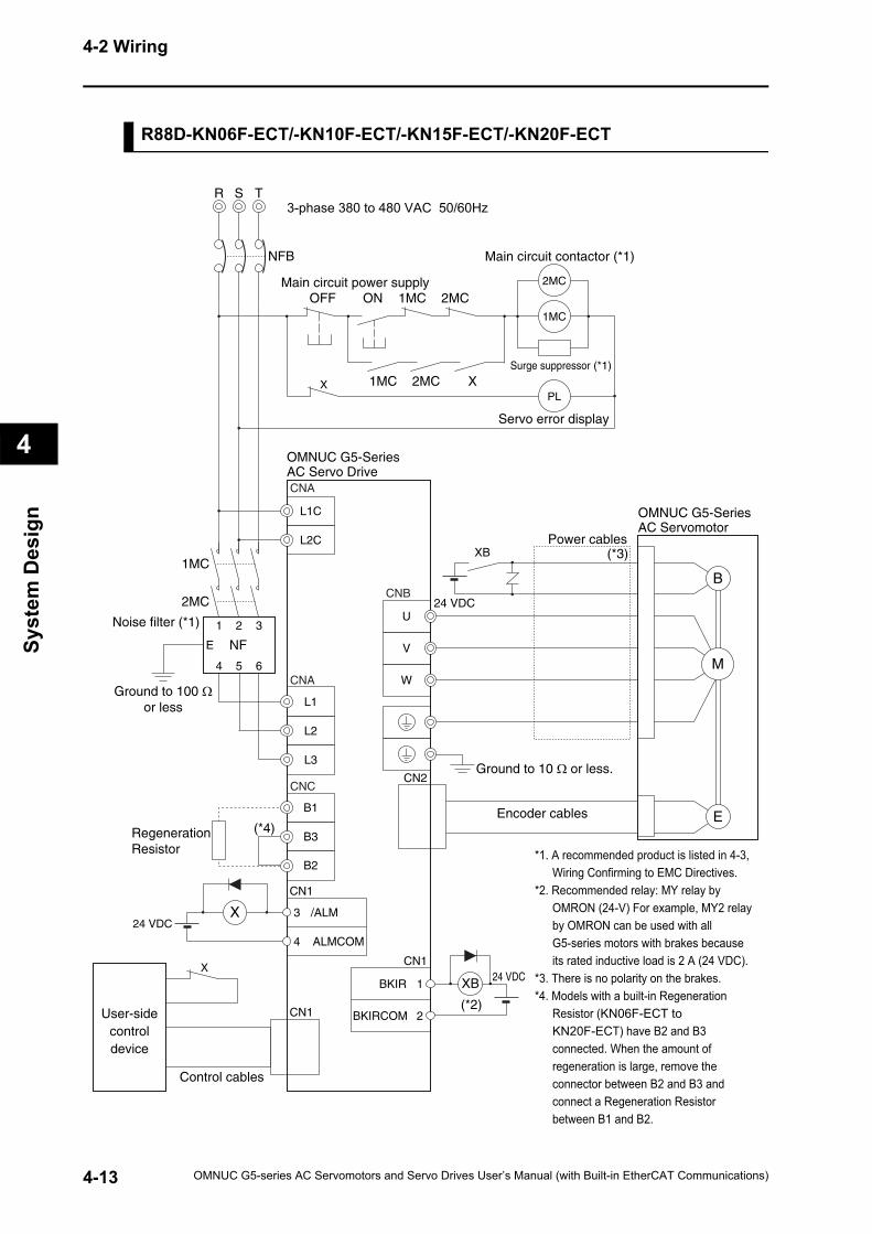
4-2 Wiring
4
Syst
em D
esig
n
R88D-KN06F-ECT/-KN10F-ECT/-KN15F-ECT/-KN20F-ECT
3-phase 380 to 480 VAC 50/60Hz
*1. A recommended product is listed in 4-3, Wiring Confirming to EMC Directives.
*2. Recommended relay: MY relay by OMRON (24-V) For example, MY2 relay by OMRON can be used with all G5-series motors with brakes because its rated inductive load is 2 A (24 VDC).
*3. There is no polarity on the brakes.*4. Models with a built-in Regeneration
Resistor (KN06F-ECT to KN20F-ECT) have B2 and B3 connected. When the amount of regeneration is large, remove the connector between B2 and B3 and connect a Regeneration Resistor between B1 and B2.
R T
NFB
S
Noise filter (*1) 1 2 3
4 5 6
E NF
Ground to 100 Ωor less
Main circuit contactor (*1)
PL
Servo error display
L1C
L2C
L1
L2
L3
OMNUC G5-SeriesAC Servo Drive
ALMCOM
/ALM3
4
User-sidecontroldevice
CN1
X24 VDC
1
2
BKIR
BKIRCOM
XB 24 VDC
Control cables
OMNUC G5-SeriesAC Servomotor
W
V
U
B
E
M
CN2
Encoder cables
Power cables
24 VDC
(*2)
CN1
CN1
B1
B3
B2
(*4)RegenerationResistor
CNB
CNC
CNA
CNA
Ground to 10 Ω or less.
X
XB
2MC
X
1MC
Surge suppressor (*1)
OFF ON
1MC X
Main circuit power supply
2MC
1MC 2MC2MC
1MC(*3)
4-13 OMNUC G5-series AC Servomotors and Servo Drives User’s Manual (with Built-in EtherCAT Communications)
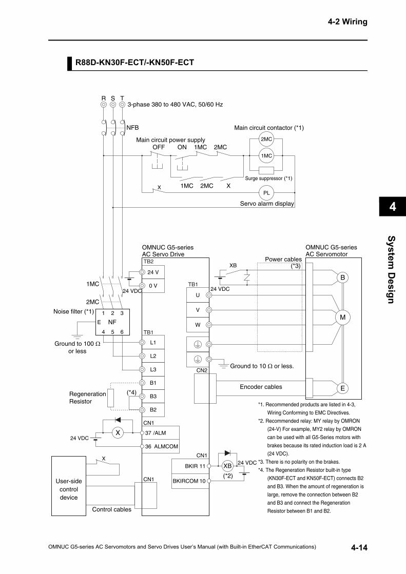
4-2 Wiring
4
System D
esign
R88D-KN30F-ECT/-KN50F-ECT
R T
NFB
S
Noise filter (*1) 1 2 3
4 5 6
E NF
Ground to 100 Ωor less
3-phase 380 to 480 VAC, 50/60 Hz
PL
Servo alarm display
24 V
0 V
OMNUC G5-seriesAC Servo Drive
ALMCOM
/ALM37
36
User-sidecontroldevice
CN1
X24 VDC
11
10
BKIR
BKIRCOM
XB 24 VDC
Control cables
OMNUC G5-seriesAC Servomotor
W
V
U
B
E
M
CN2
Encoder cables
Power cables
24 VDC
(*2)
CN1
CN1
*1. Recommended products are listed in 4-3,
Wiring Conforming to EMC Directives.
*2. Recommended relay: MY relay by OMRON
(24-V) For example, MY2 relay by OMRON
can be used with all G5-Series motors with
brakes because its rated induction load is 2 A
(24 VDC).
*3. There is no polarity on the brakes.
*4. The Regeneration Resistor built-in type
(KN30F-ECT and KN50F-ECT) connects B2
and B3. When the amount of regeneration is
large, remove the connection between B2
and B3 and connect the Regeneration
Resistor between B1 and B2.
TB1
TB2
Ground to 10 Ω or less.
X
XB
2MC
X
Main circuit contactor (*1)
1MC
Surge suppressor (*1)
OFF ON
1MC X
Main circuit power supply
2MC
1MC 2MC2MC
1MC24 VDC
(*3)
L1
L2
L3
B1
B3
B2
(*4)RegenerationResistor
TB1
4-14OMNUC G5-series AC Servomotors and Servo Drives User’s Manual (with Built-in EtherCAT Communications)
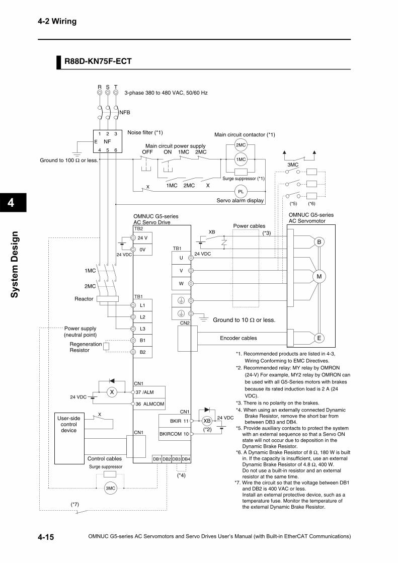
4-2 Wiring
4
Syst
em D
esig
n
R88D-KN75F-ECT
R T
NFB
S
1 2 3
4 5 6
E NF
Ground to 100 Ω or less.
PL
24 V
0V
L1
L2
L3
ALMCOM
/ALM37
36
CN1
X
11
10
BKIR
BKIRCOM
XB
W
V
U
B
E
M
CN2
(*3)
(*2)
CN1
CN1
Reactor
TB1
TB2
TB1
Ground to 10 Ω or less.
X
XB
2MC
X
1MC
OFF ON
1MC X2MC
1MC 2MC2MC
1MC
3-phase 380 to 480 VAC, 50/60 Hz
Noise filter (*1) Main circuit contactor (*1)
Main circuit power supply
OMNUC G5-seriesAC Servo Drive
OMNUC G5-seriesAC Servomotor
Power cables
Encoder cablesRegenerationResistor
User-sidecontroldevice
24 VDC
Control cables
Servo alarm display
Surge suppressor (*1)
Surge suppressor
24 VDC
24 VDC
*1. Recommended products are listed in 4-3, Wiring Conforming to EMC Directives.
*2. Recommended relay: MY relay by OMRON (24-V) For example, MY2 relay by OMRON can be used with all G5-Series motors with brakes because its rated induction load is 2 A (24 VDC).
*3. There is no polarity on the brakes. *4. When using an externally connected Dynamic
Brake Resistor, remove the short bar from between DB3 and DB4.
*5. Provide auxiliary contacts to protect the system with an external sequence so that a Servo ON state will not occur due to deposition in the Dynamic Brake Resistor.
*6. A Dynamic Brake Resistor of 8 Ω, 180 W is built in. If the capacity is insufficient, use an external Dynamic Brake Resistor of 4.8 Ω, 400 W.Do not use a built-in resistor and an external resistor at the same time.
*7. Wire the circuit so that the voltage between DB1 and DB2 is 400 VAC or less.Install an external protective device, such as a temperature fuse. Monitor the temperature of the external Dynamic Brake Resistor.
24 VDC
B1
B2
(*5) (*6)
DB1 DB2 DB3 DB4
(*4)
Power supply(neutral point)
(*7)
3MC
3MC
4-15 OMNUC G5-series AC Servomotors and Servo Drives User’s Manual (with Built-in EtherCAT Communications)
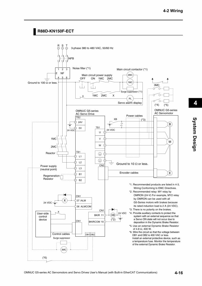
4-2 Wiring
4
System D
esign
R88D-KN150F-ECT
R T
NFB
S
1 2 3
4 5 6
E NF
Ground to 100 Ω or less.
PL
24V
0V
L1
L2
L3
ALMCOM
/ALM37
36
CN1
X
11
10
BKIR
BKIRCOM
XB
W
V
U
B
E
M
CN2
(*3)
(*2)
CN1
CN1
Reactor
TB1
TB2
TB1
Ground to 10 Ω or less.
X
XB
2MC
X
1MCOFF ON
1MC X2MC
1MC 2MC2MC
1MC
3-phase 380 to 480 VAC, 50/60 Hz
Noise filter (*1) Main circuit contactor (*1)
Main circuit power supply
OMNUC G5-seriesAC Servo Drive
OMNUC G5-seriesAC Servomotor
Power cables
Encoder cablesRegenerationResistor
User-sidecontroldevice
24 VDC
Control cables
Servo alarm display
Surge suppressor (*1)
Surge suppressor
24 VDC
24 VDC
24 VDC
*1. Recommended products are listed in 4-3, Wiring Conforming to EMC Directives.
*2. Recommended relay: MY relay by OMRON (24-V) For example, MY2 relay by OMRON can be used with all G5-Series motors with brakes because its rated induction load is 2 A (24 VDC).
*3. There is no polarity on the brakes. *4. Provide auxiliary contacts to protect the
system with an external sequence so that a Servo ON state will not occur due to deposition in the Dynamic Brake Resistor.
*5. Use an external Dynamic Brake Resistor of 4.8 Ω, 400 W.
*6. Wire the circuit so that the voltage between DB1 and DB2 is 400 VAC or less.Install an external protective device, such as a temperature fuse. Monitor the temperature of the external Dynamic Brake Resistor.
B1
B2
(*5)
(*6)
DB1 DB2
(*4)
Power supply(neutral point)
3MC
3MC
4-16OMNUC G5-series AC Servomotors and Servo Drives User’s Manual (with Built-in EtherCAT Communications)
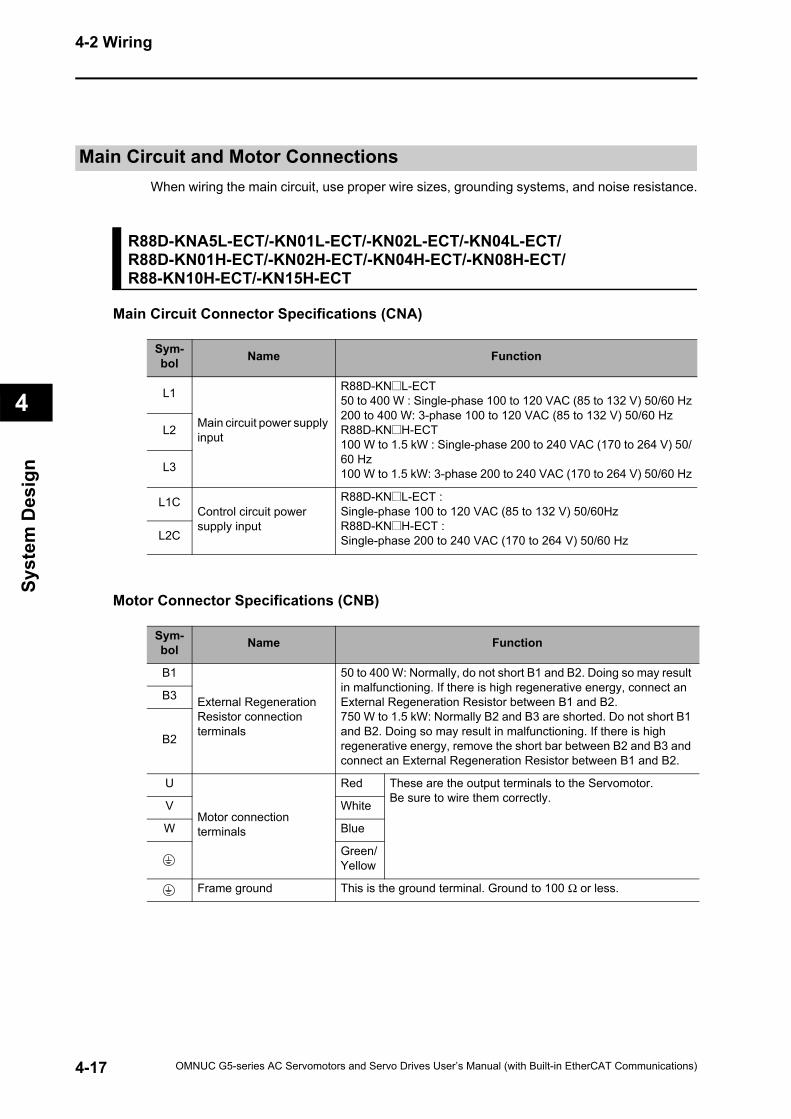
4-2 Wiring
4
Syst
em D
esig
n
Main Circuit and Motor ConnectionsWhen wiring the main circuit, use proper wire sizes, grounding systems, and noise resistance.
R88D-KNA5L-ECT/-KN01L-ECT/-KN02L-ECT/-KN04L-ECT/R88D-KN01H-ECT/-KN02H-ECT/-KN04H-ECT/-KN08H-ECT/R88-KN10H-ECT/-KN15H-ECT
Main Circuit Connector Specifications (CNA)
Motor Connector Specifications (CNB)
Sym-bol Name Function
L1
Main circuit power supply input
R88D-KN@L-ECT50 to 400 W : Single-phase 100 to 120 VAC (85 to 132 V) 50/60 Hz200 to 400 W: 3-phase 100 to 120 VAC (85 to 132 V) 50/60 HzR88D-KN@H-ECT100 W to 1.5 kW : Single-phase 200 to 240 VAC (170 to 264 V) 50/60 Hz100 W to 1.5 kW: 3-phase 200 to 240 VAC (170 to 264 V) 50/60 Hz
L2
L3
L1CControl circuit power supply input
R88D-KN@L-ECT :Single-phase 100 to 120 VAC (85 to 132 V) 50/60HzR88D-KN@H-ECT :Single-phase 200 to 240 VAC (170 to 264 V) 50/60 HzL2C
Sym-bol Name Function
B1
External Regeneration Resistor connection terminals
50 to 400 W: Normally, do not short B1 and B2. Doing so may result in malfunctioning. If there is high regenerative energy, connect an External Regeneration Resistor between B1 and B2.750 W to 1.5 kW: Normally B2 and B3 are shorted. Do not short B1 and B2. Doing so may result in malfunctioning. If there is high regenerative energy, remove the short bar between B2 and B3 and connect an External Regeneration Resistor between B1 and B2.
B3
B2
U
Motor connection terminals
Red These are the output terminals to the Servomotor.Be sure to wire them correctly.
V White
W Blue
Green/Yellow
Frame ground This is the ground terminal. Ground to 100 Ω or less.
4-17 OMNUC G5-series AC Servomotors and Servo Drives User’s Manual (with Built-in EtherCAT Communications)
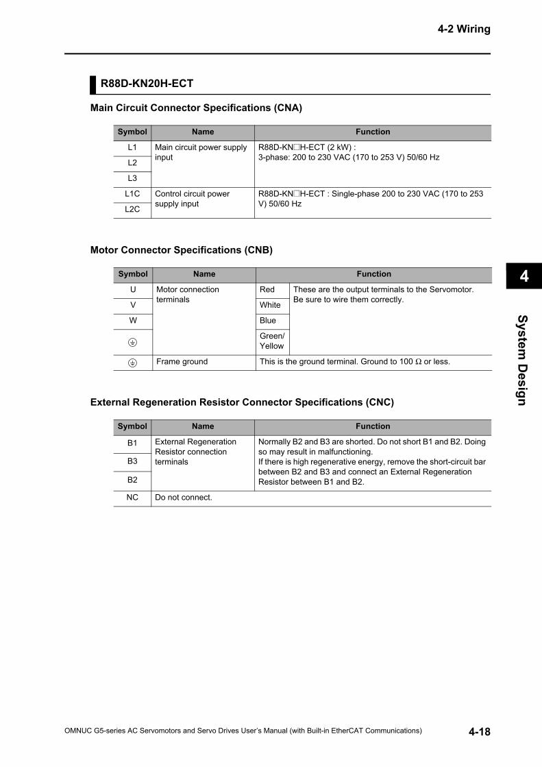
4-2 Wiring
4
System D
esign
R88D-KN20H-ECT
Main Circuit Connector Specifications (CNA)
Motor Connector Specifications (CNB)
External Regeneration Resistor Connector Specifications (CNC)
Symbol Name Function
L1 Main circuit power supply input
R88D-KN@H-ECT (2 kW) :3-phase: 200 to 230 VAC (170 to 253 V) 50/60 Hz
L2
L3
L1C Control circuit power supply input
R88D-KN@H-ECT : Single-phase 200 to 230 VAC (170 to 253 V) 50/60 Hz
L2C
Symbol Name Function
U Motor connection terminals
Red These are the output terminals to the Servomotor.Be sure to wire them correctly.
V White
W Blue
Green/Yellow
Frame ground This is the ground terminal. Ground to 100 Ω or less.
Symbol Name Function
B1 External Regeneration Resistor connection terminals
Normally B2 and B3 are shorted. Do not short B1 and B2. Doing so may result in malfunctioning.If there is high regenerative energy, remove the short-circuit bar between B2 and B3 and connect an External Regeneration Resistor between B1 and B2.
B3
B2
NC Do not connect.
4-18OMNUC G5-series AC Servomotors and Servo Drives User’s Manual (with Built-in EtherCAT Communications)
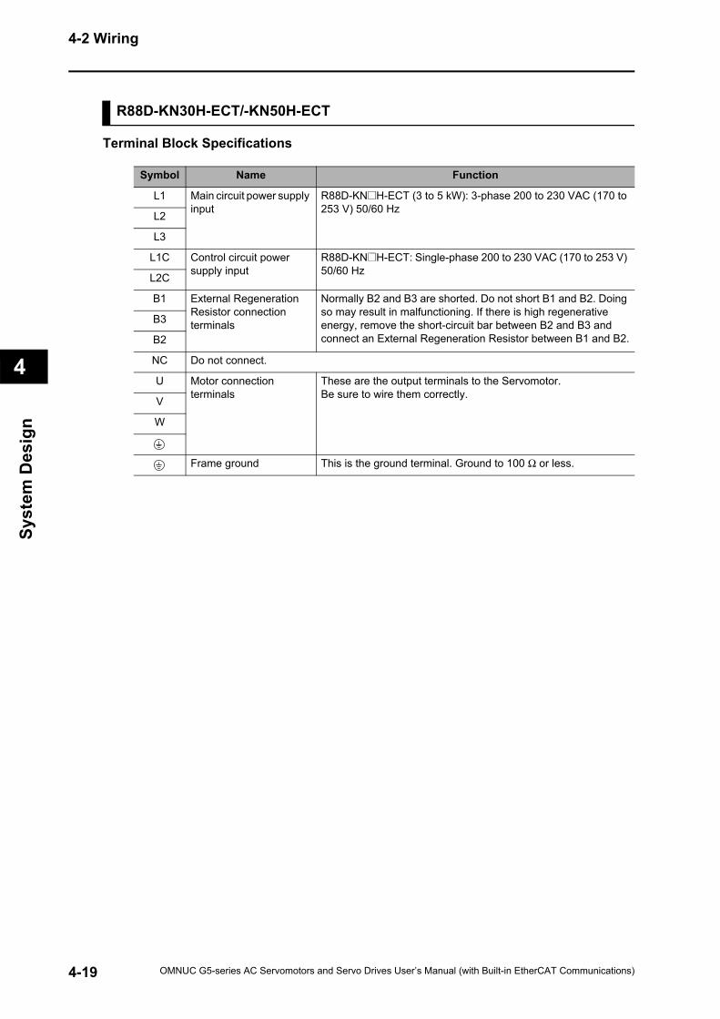
4-2 Wiring
4
Syst
em D
esig
n
R88D-KN30H-ECT/-KN50H-ECT
Terminal Block Specifications
Symbol Name Function
L1 Main circuit power supply input
R88D-KN@H-ECT (3 to 5 kW): 3-phase 200 to 230 VAC (170 to 253 V) 50/60 Hz
L2
L3
L1C Control circuit power supply input
R88D-KN@H-ECT: Single-phase 200 to 230 VAC (170 to 253 V) 50/60 Hz
L2C
B1 External Regeneration Resistor connection terminals
Normally B2 and B3 are shorted. Do not short B1 and B2. Doing so may result in malfunctioning. If there is high regenerative energy, remove the short-circuit bar between B2 and B3 and connect an External Regeneration Resistor between B1 and B2.
B3
B2
NC Do not connect.
U Motor connection terminals
These are the output terminals to the Servomotor.Be sure to wire them correctly.
V
W
Frame ground This is the ground terminal. Ground to 100 Ω or less.
4-19 OMNUC G5-series AC Servomotors and Servo Drives User’s Manual (with Built-in EtherCAT Communications)
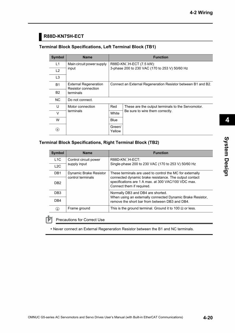
4-2 Wiring
4
System D
esign
R88D-KN75H-ECT
Terminal Block Specifications, Left Terminal Block (TB1)
Terminal Block Specifications, Right Terminal Block (TB2)
Precautions for Correct Use
Never connect an External Regeneration Resistor between the B1 and NC terminals.
Symbol Name Function
L1 Main circuit power supply input
R88D-KN@H-ECT (7.5 kW): 3-phase 200 to 230 VAC (170 to 253 V) 50/60 Hz
L2
L3
B1 External Regeneration Resistor connection terminals
Connect an External Regeneration Resistor between B1 and B2.
B2
NC Do not connect.
U Motor connection terminals
Red These are the output terminals to the Servomotor.Be sure to wire them correctly.
V White
W Blue
Green/Yellow
Symbol Name Function
L1C Control circuit power supply input
R88D-KN@H-ECT: Single-phase 200 to 230 VAC (170 to 253 V) 50/60 Hz
L2C
DB1 Dynamic Brake Resistor control terminals
These terminals are used to control the MC for externally connected dynamic brake resistance. The output contact specifications are 1 A max. at 300 VAC/100 VDC max.Connect them if required.
DB2
DB3 Normally DB3 and DB4 are shorted.When using an externally connected Dynamic Brake Resistor, remove the short bar from between DB3 and DB4.DB4
Frame ground This is the ground terminal. Ground it to 100 Ω or less.
4-20OMNUC G5-series AC Servomotors and Servo Drives User’s Manual (with Built-in EtherCAT Communications)
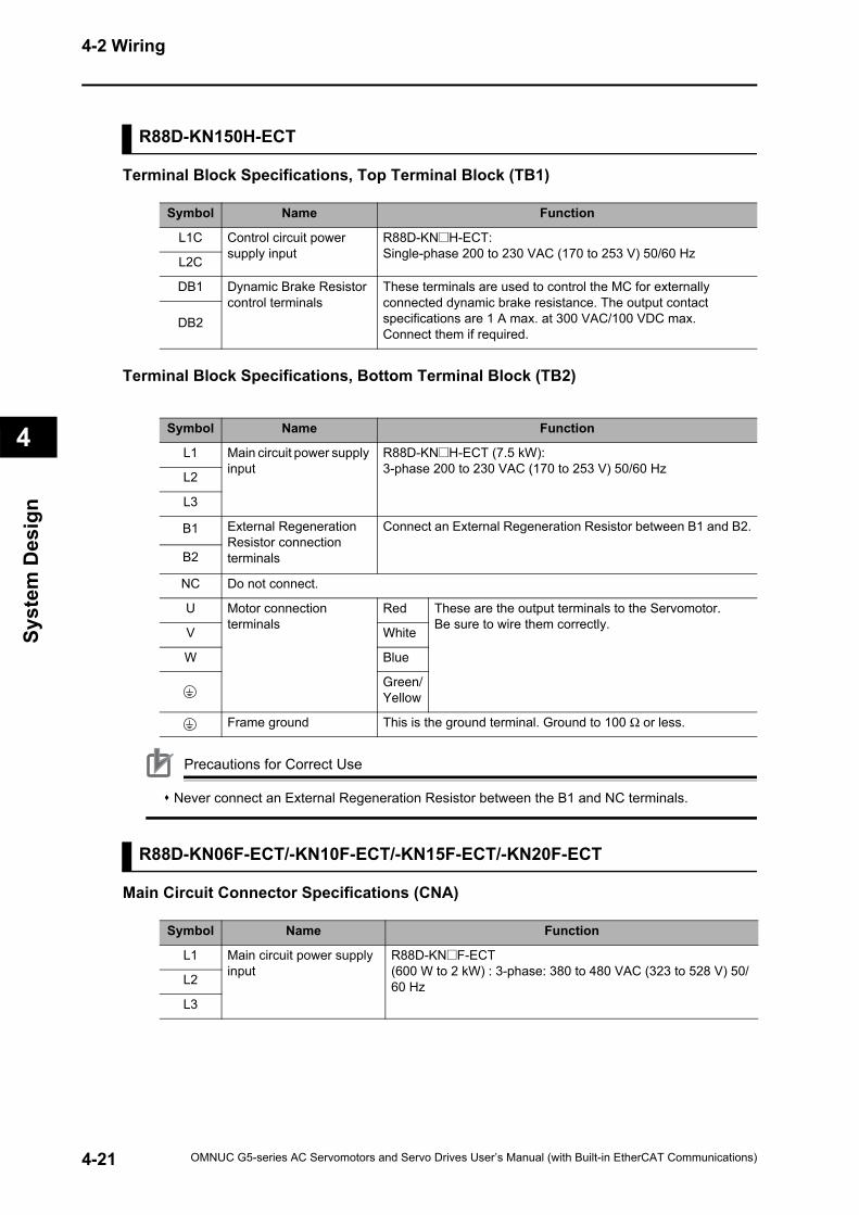
4-2 Wiring
4
Syst
em D
esig
n
R88D-KN150H-ECT
Terminal Block Specifications, Top Terminal Block (TB1)
Terminal Block Specifications, Bottom Terminal Block (TB2)
Precautions for Correct Use
Never connect an External Regeneration Resistor between the B1 and NC terminals.
R88D-KN06F-ECT/-KN10F-ECT/-KN15F-ECT/-KN20F-ECT
Main Circuit Connector Specifications (CNA)
Symbol Name Function
L1C Control circuit power supply input
R88D-KN@H-ECT: Single-phase 200 to 230 VAC (170 to 253 V) 50/60 Hz
L2C
DB1 Dynamic Brake Resistor control terminals
These terminals are used to control the MC for externally connected dynamic brake resistance. The output contact specifications are 1 A max. at 300 VAC/100 VDC max.Connect them if required.
DB2
Symbol Name Function
L1 Main circuit power supply input
R88D-KN@H-ECT (7.5 kW): 3-phase 200 to 230 VAC (170 to 253 V) 50/60 Hz
L2
L3
B1 External Regeneration Resistor connection terminals
Connect an External Regeneration Resistor between B1 and B2.
B2
NC Do not connect.
U Motor connection terminals
Red These are the output terminals to the Servomotor.Be sure to wire them correctly.
V White
W Blue
Green/Yellow
Frame ground This is the ground terminal. Ground to 100 Ω or less.
Symbol Name Function
L1 Main circuit power supply input
R88D-KN@F-ECT(600 W to 2 kW) : 3-phase: 380 to 480 VAC (323 to 528 V) 50/60 HzL2
L3
4-21 OMNUC G5-series AC Servomotors and Servo Drives User’s Manual (with Built-in EtherCAT Communications)
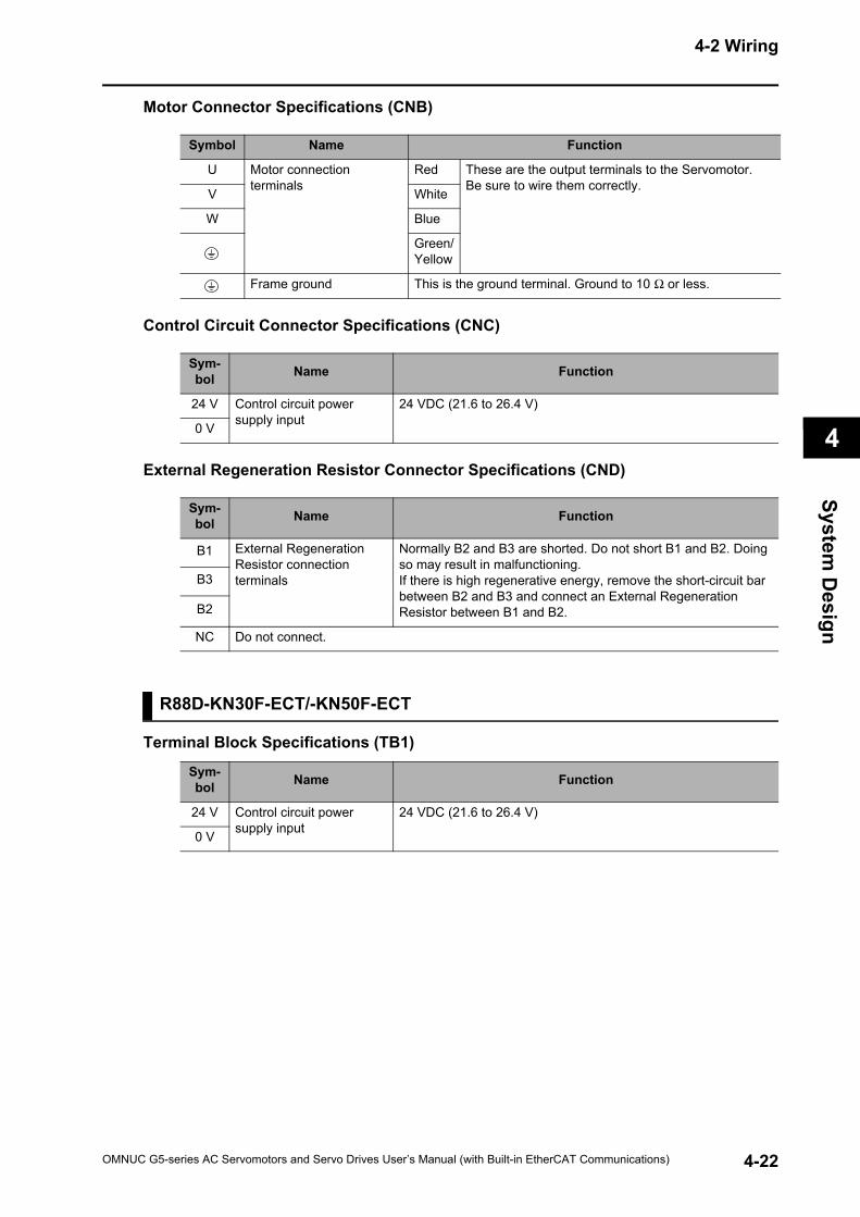
4-2 Wiring
4
System D
esign
Motor Connector Specifications (CNB)
Control Circuit Connector Specifications (CNC)
External Regeneration Resistor Connector Specifications (CND)
R88D-KN30F-ECT/-KN50F-ECT
Terminal Block Specifications (TB1)
Symbol Name Function
U Motor connection terminals
Red These are the output terminals to the Servomotor.Be sure to wire them correctly.
V White
W Blue
Green/Yellow
Frame ground This is the ground terminal. Ground to 10 Ω or less.
Sym-bol Name Function
24 V Control circuit power supply input
24 VDC (21.6 to 26.4 V)
0 V
Sym-bol Name Function
B1 External Regeneration Resistor connection terminals
Normally B2 and B3 are shorted. Do not short B1 and B2. Doing so may result in malfunctioning.If there is high regenerative energy, remove the short-circuit bar between B2 and B3 and connect an External Regeneration Resistor between B1 and B2.
B3
B2
NC Do not connect.
Sym-bol Name Function
24 V Control circuit power supply input
24 VDC (21.6 to 26.4 V)
0 V
4-22OMNUC G5-series AC Servomotors and Servo Drives User’s Manual (with Built-in EtherCAT Communications)
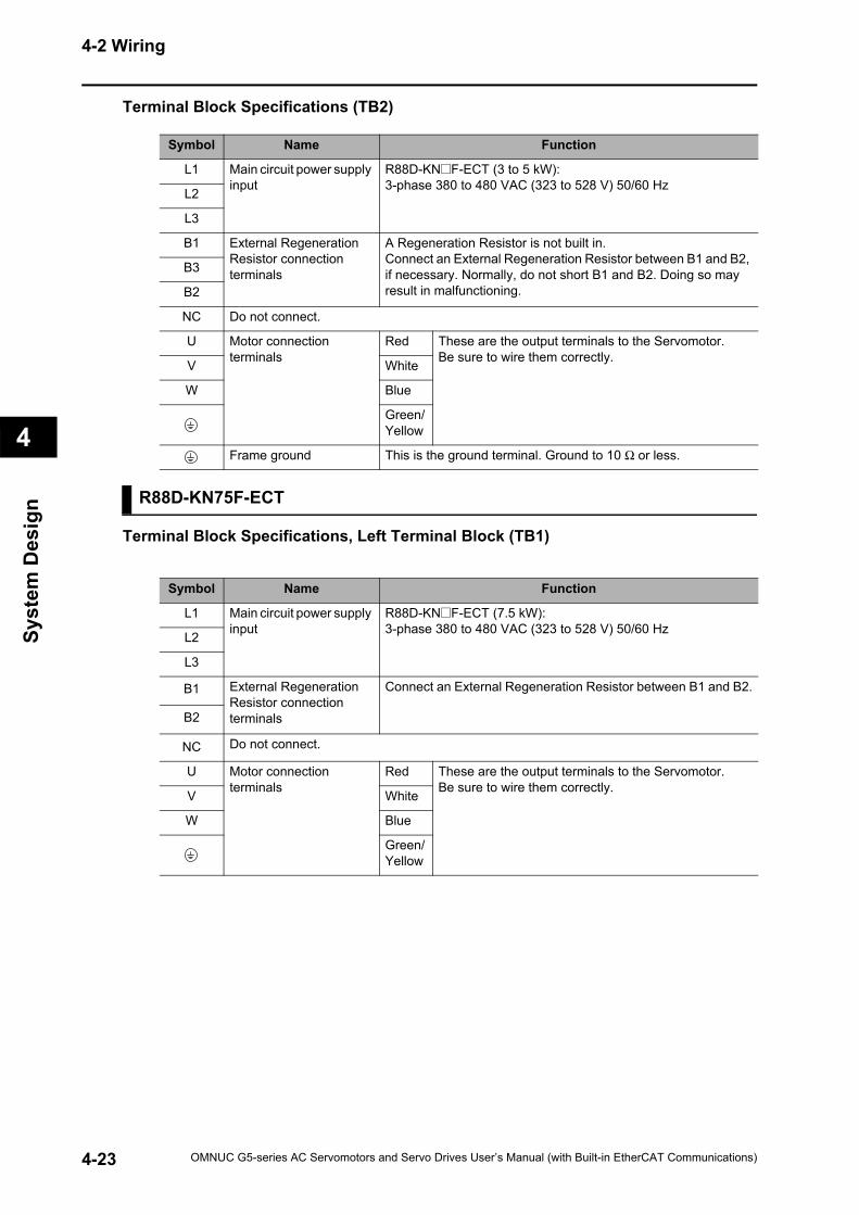
4-2 Wiring
4
Syst
em D
esig
n
Terminal Block Specifications (TB2)
R88D-KN75F-ECT
Terminal Block Specifications, Left Terminal Block (TB1)
Symbol Name Function
L1 Main circuit power supply input
R88D-KN@F-ECT (3 to 5 kW): 3-phase 380 to 480 VAC (323 to 528 V) 50/60 Hz
L2
L3
B1 External Regeneration Resistor connection terminals
A Regeneration Resistor is not built in.Connect an External Regeneration Resistor between B1 and B2, if necessary. Normally, do not short B1 and B2. Doing so may result in malfunctioning.
B3
B2
NC Do not connect.
U Motor connection terminals
Red These are the output terminals to the Servomotor.Be sure to wire them correctly.
V White
W Blue
Green/Yellow
Frame ground This is the ground terminal. Ground to 10 Ω or less.
Symbol Name Function
L1 Main circuit power supply input
R88D-KN@F-ECT (7.5 kW): 3-phase 380 to 480 VAC (323 to 528 V) 50/60 Hz
L2
L3
B1 External Regeneration Resistor connection terminals
Connect an External Regeneration Resistor between B1 and B2.
B2
NC Do not connect.
U Motor connection terminals
Red These are the output terminals to the Servomotor.Be sure to wire them correctly.
V White
W Blue
Green/Yellow
4-23 OMNUC G5-series AC Servomotors and Servo Drives User’s Manual (with Built-in EtherCAT Communications)
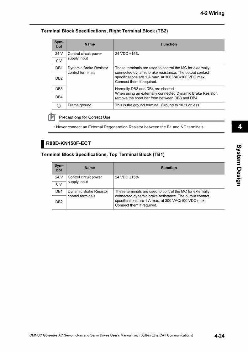
4-2 Wiring
4
System D
esign
Terminal Block Specifications, Right Terminal Block (TB2)
Precautions for Correct Use
Never connect an External Regeneration Resistor between the B1 and NC terminals.
R88D-KN150F-ECT
Terminal Block Specifications, Top Terminal Block (TB1)
Sym-bol Name Function
24 V Control circuit power supply input
24 VDC ±15%
0 V
DB1 Dynamic Brake Resistor control terminals
These terminals are used to control the MC for externally connected dynamic brake resistance. The output contact specifications are 1 A max. at 300 VAC/100 VDC max.Connect them if required.
DB2
DB3 Normally DB3 and DB4 are shorted.When using an externally connected Dynamic Brake Resistor, remove the short bar from between DB3 and DB4.DB4
Frame ground This is the ground terminal. Ground to 10 Ω or less.
Sym-bol Name Function
24 V Control circuit power supply input
24 VDC ±15%
0 V
DB1 Dynamic Brake Resistor control terminals
These terminals are used to control the MC for externally connected dynamic brake resistance. The output contact specifications are 1 A max. at 300 VAC/100 VDC max.Connect them if required.
DB2
4-24OMNUC G5-series AC Servomotors and Servo Drives User’s Manual (with Built-in EtherCAT Communications)
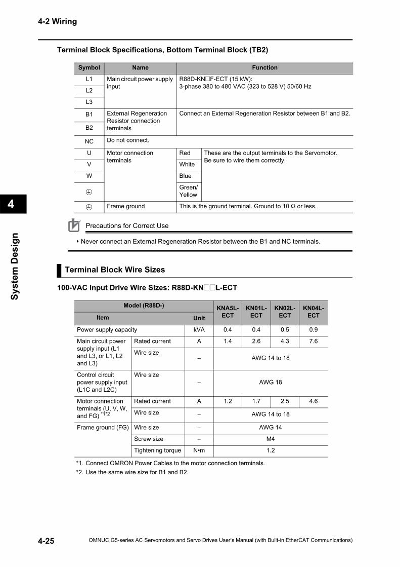
4-2 Wiring
4
Syst
em D
esig
n
Terminal Block Specifications, Bottom Terminal Block (TB2)
Precautions for Correct Use
Never connect an External Regeneration Resistor between the B1 and NC terminals.
Terminal Block Wire Sizes
100-VAC Input Drive Wire Sizes: R88D-KN@@L-ECT
*1. Connect OMRON Power Cables to the motor connection terminals.*2. Use the same wire size for B1 and B2.
Symbol Name Function
L1 Main circuit power supply input
R88D-KN@F-ECT (15 kW): 3-phase 380 to 480 VAC (323 to 528 V) 50/60 Hz
L2
L3
B1 External Regeneration Resistor connection terminals
Connect an External Regeneration Resistor between B1 and B2.
B2
NC Do not connect.
U Motor connection terminals
Red These are the output terminals to the Servomotor.Be sure to wire them correctly.
V White
W Blue
Green/Yellow
Frame ground This is the ground terminal. Ground to 10 Ω or less.
Model (R88D-) KNA5L-ECT
KN01L-ECT
KN02L-ECT
KN04L-ECTItem Unit
Power supply capacity kVA 0.4 0.4 0.5 0.9
Main circuit power supply input (L1 and L3, or L1, L2 and L3)
Rated current A 1.4 2.6 4.3 7.6
Wire size− AWG 14 to 18
Control circuit power supply input (L1C and L2C)
Wire size− AWG 18
Motor connection terminals (U, V, W, and FG) *1*2
Rated current A 1.2 1.7 2.5 4.6
Wire size − AWG 14 to 18
Frame ground (FG) Wire size − AWG 14
Screw size − M4
Tightening torque N•m 1.2
4-25 OMNUC G5-series AC Servomotors and Servo Drives User’s Manual (with Built-in EtherCAT Communications)
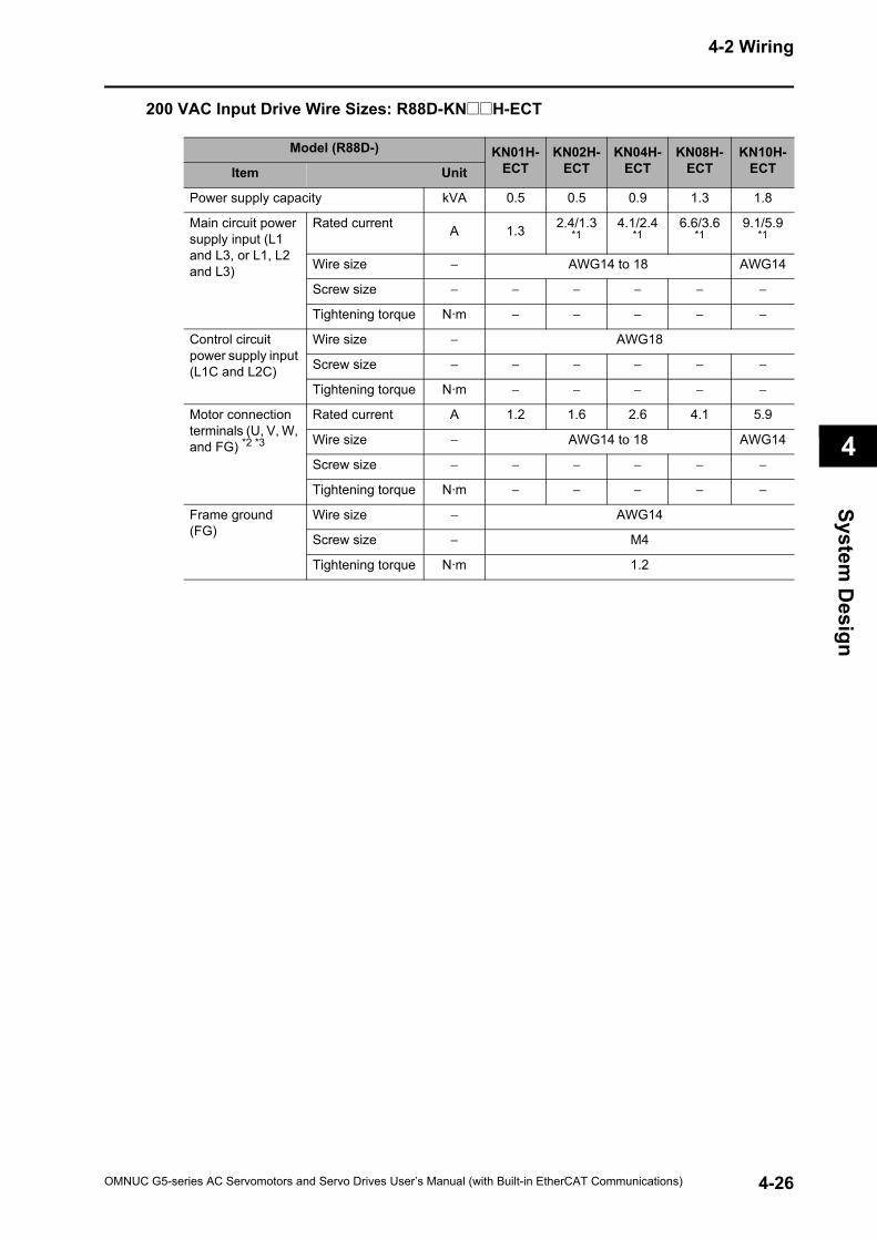
4-2 Wiring
4
System D
esign
200 VAC Input Drive Wire Sizes: R88D-KN@@H-ECT
Model (R88D-) KN01H-ECT
KN02H-ECT
KN04H-ECT
KN08H-ECT
KN10H-ECTItem Unit
Power supply capacity kVA 0.5 0.5 0.9 1.3 1.8
Main circuit power supply input (L1 and L3, or L1, L2 and L3)
Rated current A 1.3 2.4/1.3*1
4.1/2.4*1
6.6/3.6*1
9.1/5.9*1
Wire size − AWG14 to 18 AWG14
Screw size − − − − − −
Tightening torque N·m − − − − −
Control circuit power supply input (L1C and L2C)
Wire size − AWG18
Screw size − − − − − −
Tightening torque N·m − − − − −
Motor connection terminals (U, V, W, and FG) *2 *3
Rated current A 1.2 1.6 2.6 4.1 5.9
Wire size − AWG14 to 18 AWG14
Screw size − − − − − −
Tightening torque N·m − − − − −
Frame ground (FG)
Wire size − AWG14
Screw size − M4
Tightening torque N·m 1.2
4-26OMNUC G5-series AC Servomotors and Servo Drives User’s Manual (with Built-in EtherCAT Communications)
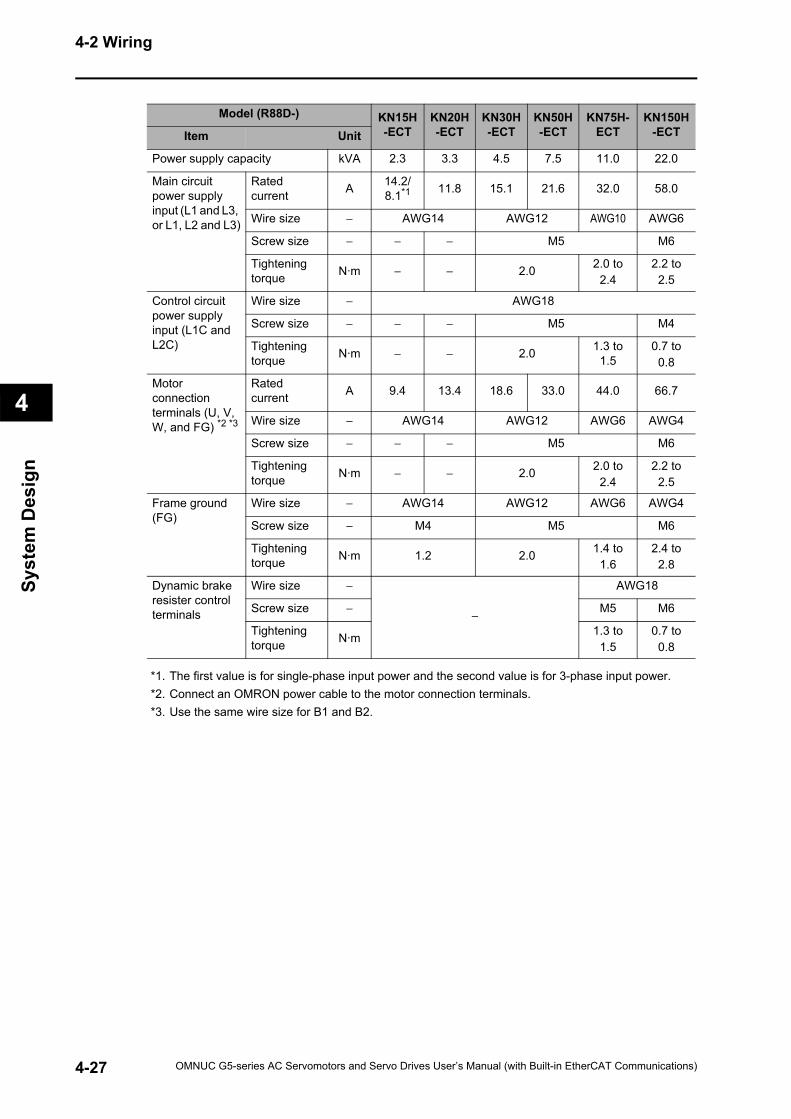
4-2 Wiring
4
Syst
em D
esig
n
*1. The first value is for single-phase input power and the second value is for 3-phase input power.*2. Connect an OMRON power cable to the motor connection terminals.*3. Use the same wire size for B1 and B2.
Model (R88D-) KN15H-ECT
KN20H-ECT
KN30H-ECT
KN50H-ECT
KN75H-ECT
KN150H-ECTItem Unit
Power supply capacity kVA 2.3 3.3 4.5 7.5 11.0 22.0
Main circuit power supply input (L1 and L3, or L1, L2 and L3)
Rated current A 14.2/
8.1*1 11.8 15.1 21.6 32.0 58.0
Wire size − AWG14 AWG12 AWG10 AWG6
Screw size − − − M5 M6
Tightening torque N·m − − 2.0 2.0 to
2.42.2 to 2.5
Control circuit power supply input (L1C and L2C)
Wire size − AWG18
Screw size − − − M5 M4
Tightening torque N·m − − 2.0 1.3 to
1.50.7 to 0.8
Motor connection terminals (U, V, W, and FG) *2 *3
Rated current A 9.4 13.4 18.6 33.0 44.0 66.7
Wire size − AWG14 AWG12 AWG6 AWG4
Screw size − − − M5 M6
Tightening torque N·m − − 2.0 2.0 to
2.42.2 to 2.5
Frame ground (FG)
Wire size − AWG14 AWG12 AWG6 AWG4
Screw size − M4 M5 M6
Tightening torque N·m 1.2 2.0 1.4 to
1.62.4 to 2.8
Dynamic brake resister control terminals
Wire size −
−
AWG18
Screw size − M5 M6
Tightening torque N·m 1.3 to
1.50.7 to 0.8
4-27 OMNUC G5-series AC Servomotors and Servo Drives User’s Manual (with Built-in EtherCAT Communications)
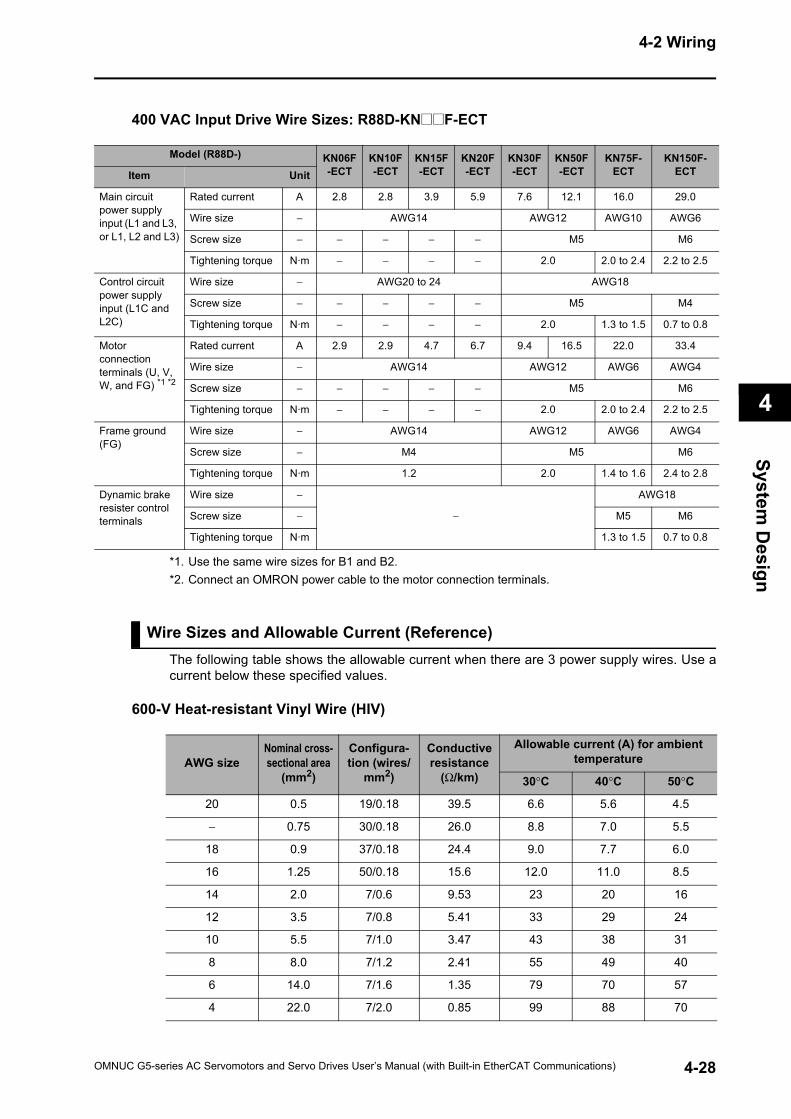
4-2 Wiring
4
System D
esign
400 VAC Input Drive Wire Sizes: R88D-KN@@F-ECT
*1. Use the same wire sizes for B1 and B2.*2. Connect an OMRON power cable to the motor connection terminals.
Wire Sizes and Allowable Current (Reference)The following table shows the allowable current when there are 3 power supply wires. Use acurrent below these specified values.
600-V Heat-resistant Vinyl Wire (HIV)
Model (R88D-) KN06F-ECT
KN10F-ECT
KN15F-ECT
KN20F-ECT
KN30F-ECT
KN50F-ECT
KN75F-ECT
KN150F-ECTItem Unit
Main circuit power supply input (L1 and L3, or L1, L2 and L3)
Rated current A 2.8 2.8 3.9 5.9 7.6 12.1 16.0 29.0
Wire size − AWG14 AWG12 AWG10 AWG6
Screw size − − − − − M5 M6
Tightening torque N·m − − − − 2.0 2.0 to 2.4 2.2 to 2.5
Control circuit power supply input (L1C and L2C)
Wire size − AWG20 to 24 AWG18
Screw size − − − − − M5 M4
Tightening torque N·m − − − − 2.0 1.3 to 1.5 0.7 to 0.8
Motor connection terminals (U, V, W, and FG) *1 *2
Rated current A 2.9 2.9 4.7 6.7 9.4 16.5 22.0 33.4
Wire size − AWG14 AWG12 AWG6 AWG4
Screw size − − − − − M5 M6
Tightening torque N·m − − − − 2.0 2.0 to 2.4 2.2 to 2.5
Frame ground (FG)
Wire size − AWG14 AWG12 AWG6 AWG4
Screw size − M4 M5 M6
Tightening torque N·m 1.2 2.0 1.4 to 1.6 2.4 to 2.8
Dynamic brake resister control terminals
Wire size −
−
AWG18
Screw size − M5 M6
Tightening torque N·m 1.3 to 1.5 0.7 to 0.8
AWG sizeNominal cross-sectional area
(mm2)
Configura-tion (wires/
mm2)
Conductive resistance
(Ω/km)
Allowable current (A) for ambient temperature
30°C 40°C 50°C
20 0.5 19/0.18 39.5 6.6 5.6 4.5
− 0.75 30/0.18 26.0 8.8 7.0 5.5
18 0.9 37/0.18 24.4 9.0 7.7 6.0
16 1.25 50/0.18 15.6 12.0 11.0 8.5
14 2.0 7/0.6 9.53 23 20 16
12 3.5 7/0.8 5.41 33 29 24
10 5.5 7/1.0 3.47 43 38 31
8 8.0 7/1.2 2.41 55 49 40
6 14.0 7/1.6 1.35 79 70 57
4 22.0 7/2.0 0.85 99 88 70
4-28OMNUC G5-series AC Servomotors and Servo Drives User’s Manual (with Built-in EtherCAT Communications)
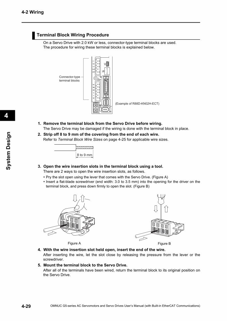
4-2 Wiring
4
Syst
em D
esig
n
Terminal Block Wiring ProcedureOn a Servo Drive with 2.0 kW or less, connector-type terminal blocks are used.The procedure for wiring these terminal blocks is explained below.
1. Remove the terminal block from the Servo Drive before wiring.The Servo Drive may be damaged if the wiring is done with the terminal block in place.
2. Strip off 8 to 9 mm of the covering from the end of each wire.Refer to Terminal Block Wire Sizes on page 4-25 for applicable wire sizes.
3. Open the wire insertion slots in the terminal block using a tool.There are 2 ways to open the wire insertion slots, as follows.
Pry the slot open using the lever that comes with the Servo Drive. (Figure A)Insert a flat-blade screwdriver (end width: 3.0 to 3.5 mm) into the opening for the driver on theterminal block, and press down firmly to open the slot. (Figure B)
4. With the wire insertion slot held open, insert the end of the wire.After inserting the wire, let the slot close by releasing the pressure from the lever or thescrewdriver.
5. Mount the terminal block to the Servo Drive.After all of the terminals have been wired, return the terminal block to its original position onthe Servo Drive.
Connector-typeterminal blocks
(Example of R88D-KN02H-ECT)
8 to 9 mm
Figure A Figure B
4-29 OMNUC G5-series AC Servomotors and Servo Drives User’s Manual (with Built-in EtherCAT Communications)
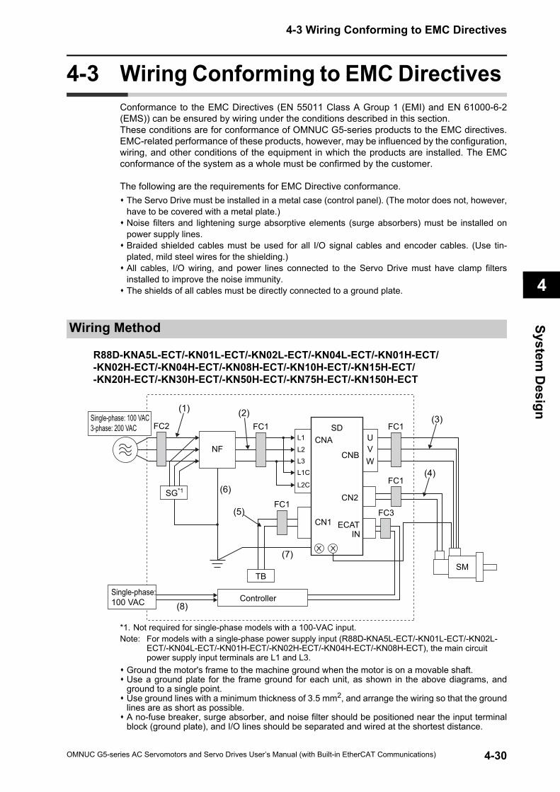
4-3 Wiring Conforming to EMC Directives
4
System D
esign
4-3 Wiring Conforming to EMC DirectivesConformance to the EMC Directives (EN 55011 Class A Group 1 (EMI) and EN 61000-6-2(EMS)) can be ensured by wiring under the conditions described in this section.These conditions are for conformance of OMNUC G5-series products to the EMC directives.EMC-related performance of these products, however, may be influenced by the configuration,wiring, and other conditions of the equipment in which the products are installed. The EMCconformance of the system as a whole must be confirmed by the customer.
The following are the requirements for EMC Directive conformance.The Servo Drive must be installed in a metal case (control panel). (The motor does not, however,have to be covered with a metal plate.)Noise filters and lightening surge absorptive elements (surge absorbers) must be installed onpower supply lines.Braided shielded cables must be used for all I/O signal cables and encoder cables. (Use tin-plated, mild steel wires for the shielding.)All cables, I/O wiring, and power lines connected to the Servo Drive must have clamp filtersinstalled to improve the noise immunity.The shields of all cables must be directly connected to a ground plate.
Wiring Method
R88D-KNA5L-ECT/-KN01L-ECT/-KN02L-ECT/-KN04L-ECT/-KN01H-ECT/-KN02H-ECT/-KN04H-ECT/-KN08H-ECT/-KN10H-ECT/-KN15H-ECT/-KN20H-ECT/-KN30H-ECT/-KN50H-ECT/-KN75H-ECT/-KN150H-ECT
*1. Not required for single-phase models with a 100-VAC input. Note: For models with a single-phase power supply input (R88D-KNA5L-ECT/-KN01L-ECT/-KN02L-
ECT/-KN04L-ECT/-KN01H-ECT/-KN02H-ECT/-KN04H-ECT/-KN08H-ECT), the main circuit power supply input terminals are L1 and L3.
Ground the motor's frame to the machine ground when the motor is on a movable shaft.Use a ground plate for the frame ground for each unit, as shown in the above diagrams, andground to a single point.Use ground lines with a minimum thickness of 3.5 mm2, and arrange the wiring so that the groundlines are as short as possible.A no-fuse breaker, surge absorber, and noise filter should be positioned near the input terminalblock (ground plate), and I/O lines should be separated and wired at the shortest distance.
L1
L2
L3
L1C
L2CSG*1
NF
FC1 FC1SD
FC3FC1
CNA
CN1
CNB
CN2
UVW
SM
(3)
(4)
(1) (2)
(6)
(5)
(7)
(8)
FC2
ECATIN
FC1
TB
Single-phase: 100 VAC3-phase: 200 VAC
Single-phase:100 VAC Controller
4-30OMNUC G5-series AC Servomotors and Servo Drives User’s Manual (with Built-in EtherCAT Communications)
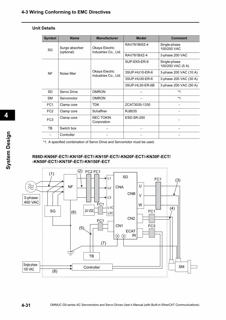
4-3 Wiring Conforming to EMC Directives
4
Syst
em D
esig
n
Unit Details
*1. A specified combination of Servo Drive and Servomotor must be used.
R88D-KN06F-ECT/-KN10F-ECT/-KN15F-ECT/-KN20F-ECT/-KN30F-ECT/-KN50F-ECT/-KN75F-ECT/-KN150F-ECT
Symbol Name Manufacturer Model Comment
SG Surge absorber (optional)
Okaya Electric Industries Co., Ltd.
RAV781BWZ-4 Single-phase 100/200 VAC
RAV781BXZ-4 3-phase 200 VAC
NF Noise filter Okaya Electric Industries Co., Ltd.
SUP-EK5-ER-6 Single-phase 100/200 VAC (5 A)
3SUP-HU10-ER-6 3-phase 200 VAC (10 A)
3SUP-HU30-ER-6 3-phase 200 VAC (30 A)
3SUP-HL50-ER-6B 3-phase 200 VAC (50 A)
SD Servo Drive OMRON − *1
SM Servomotor OMRON − *1
FC1 Clamp core TDK ZCAT3035-1330 −
FC2 Clamp core Schaffner RJ8035 −
FC3 Clamp core NEC TOKIN Corporation
ESD-SR-250 −
TB Switch box − − −
- Controller − − −
Single-phase: 100 VAC
24 VDC
3-phase: 400 VAC
Controller
L1
L2
L3
L1C
L2CSG
NF
FC1
FC1SD
FC1
FC1
CNA
CN1
CNB
CN2
U
V
W
SM
(3)
(4)
(1)(2)
(6)
(5)
(7)
(8)
FC2
FC1
FC3ECAT
IN
TB
4-31 OMNUC G5-series AC Servomotors and Servo Drives User’s Manual (with Built-in EtherCAT Communications)
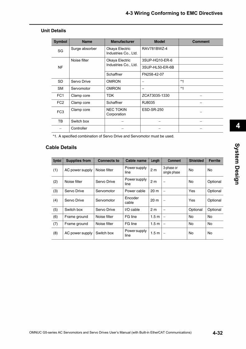
4-3 Wiring Conforming to EMC Directives
4
System D
esign
Unit Details
*1. A specified combination of Servo Drive and Servomotor must be used.
Cable Details
Symbol Name Manufacturer Model Comment
SG Surge absorber Okaya Electric Industries Co., Ltd.
RAV781BWZ-4
NF
Noise filter Okaya Electric Industries Co., Ltd.
3SUP-HQ10-ER-6
3SUP-HL50-ER-6B
Schaffner FN258-42-07
SD Servo Drive OMRON − *1
SM Servomotor OMRON − *1
FC1 Clamp core TDK ZCAT3035-1330 −
FC2 Clamp core Schaffner RJ8035 −
FC3 Clamp core NEC TOKIN Corporation
ESD-SR-250 −
TB Switch box − − −
− Controller − − −
Symbol Supplies from Connects to Cable name Length Comment Shielded Ferrite
(1) AC power supply Noise filterPower supply line
2 m3-phase or single phase
No No
(2) Noise filter Servo DrivePower supply line
2 m − No Optional
(3) Servo Drive Servomotor Power cable 20 m − Yes Optional
(4) Servo Drive ServomotorEncoder cable
20 m − Yes Optional
(5) Switch box Servo Drive I/O cable 2 m − Optional Optional
(6) Frame ground Noise filter FG line 1.5 m − No No
(7) Frame ground Noise filter FG line 1.5 m − No No
(8) AC power supply Switch boxPower supply line
1.5 m − No No
4-32OMNUC G5-series AC Servomotors and Servo Drives User’s Manual (with Built-in EtherCAT Communications)
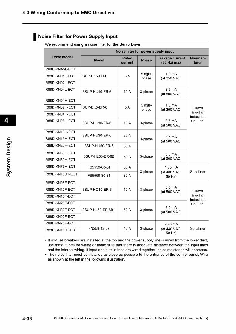
4-3 Wiring Conforming to EMC Directives
4
Syst
em D
esig
n
Noise Filter for Power Supply InputWe recommend using a noise filter for the Servo Drive.
If no-fuse breakers are installed at the top and the power supply line is wired from the lower duct,use metal tubes for wiring or make sure that there is adequate distance between the input linesand the internal wiring. If input and output lines are wired together, noise resistance will decrease.The noise filter must be installed as close as possible to the entrance of the control panel. Wireas shown at the left in the following illustration.
Drive modelNoise filter for power supply input
Model Rated current Phase Leakage current
(60 Hz) maxManufac-
turer
R88D-KNA5L-ECT
SUP-EK5-ER-6 5 A Single-phase
1.0 mA(at 250 VAC)
Okaya Electric
Industries Co., Ltd.
R88D-KN01L-ECT
R88D-KN02L-ECT
R88D-KN04L-ECT 3SUP-HU10-ER-6 10 A 3-phase 3.5 mA(at 500 VAC)
R88D-KN01H-ECT
SUP-EK5-ER-6 5 A Single-phase
1.0 mA(at 250 VAC)R88D-KN02H-ECT
R88D-KN04H-ECT
R88D-KN08H-ECT 3SUP-HU10-ER-6 10 A 3-phase 3.5 mA(at 500 VAC)
R88D-KN10H-ECT3SUP-HU30-ER-6 30 A
3-phase 3.5 mA(at 500 VAC)
R88D-KN15H-ECT
R88D-KN20H-ECT 3SUP-HU50-ER-6 50 A
R88D-KN30H-ECT3SUP-HL50-ER-6B 50 A 3-phase 8.0 mA
(at 500 VAC)R88D-KN50H-ECT
R88D-KN75H-ECT FS5559-60-34 60 A3-phase
1.35 mA(at 480 VAC/
50 Hz)Schaffner
R88D-KN150H-ECT FS5559-80-34 80 A
R88D-KN06F-ECT
3SUP-HQ10-ER-6 10 A 3-phase 3.5 mA(at 500 VAC) Okaya
Electric Industries Co., Ltd.
R88D-KN10F-ECT
R88D-KN15F-ECT
R88D-KN20F-ECT
3SUP-HL50-ER-6B 50 A 3-phase 8.0 mA(at 500 VAC)R88D-KN30F-ECT
R88D-KN50F-ECT
R88D-KN75F-ECTFN258-42-07 42 A 3-phase
25.8 mA(at 440 VAC/
50 Hz)SchaffnerR88D-KN150F-ECT
4-33 OMNUC G5-series AC Servomotors and Servo Drives User’s Manual (with Built-in EtherCAT Communications)
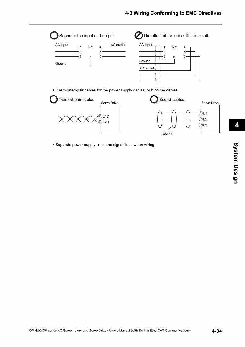
4-3 Wiring Conforming to EMC Directives
4
System D
esign
Use twisted-pair cables for the power supply cables, or bind the cables.
Separate power supply lines and signal lines when wiring.
Separate the input and output. The effect of the noise filter is small.
NF123
456E
NF123
456E
AC input AC input
GroundGround
AC output
AC output
Twisted-pair cables Bound cablesServo Drive
L1CL1
L2
L3L2C
Servo Drive
Binding
4-34OMNUC G5-series AC Servomotors and Servo Drives User’s Manual (with Built-in EtherCAT Communications)
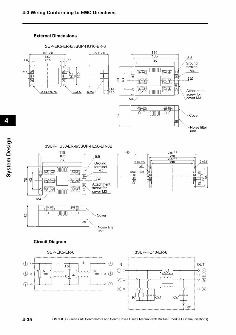
4-3 Wiring Conforming to EMC Directives
4
Syst
em D
esig
n
External Dimensions
SUP-EK5-ER-6/3SUP-HQ10-ER-6
3SUP-HU30-ER-6/3SUP-HL50-ER-6B
Circuit Diagram
SUP-EK5-ER-6 3SUP-HQ10-ER-6
105115
5.5
437052
10
95 Ground terminal
M4
Attachment screw for cover M3
Cover
Noise filter unit
M4
50.0
60.0
12.0
10.0
11.613.0
75.07.0
2.0
88.0100±2.0 53.1±2.0
5.0
2-φ4.5×6.75 2-φ4.5 6-M4
105115
5.5
437052
10
95 Ground terminal
M4
Cover
Noise filter unit
M4
Attachment screw for cover M3
2-φ5.5
120
90±1
.01813
286±3.0
240
150270
255±1.0
2-φ5.5×7M6
M6
CxRCy
CyCx
L L
Cx1Cx1R
L1
Cy1
OUTIN
4-35 OMNUC G5-series AC Servomotors and Servo Drives User’s Manual (with Built-in EtherCAT Communications)
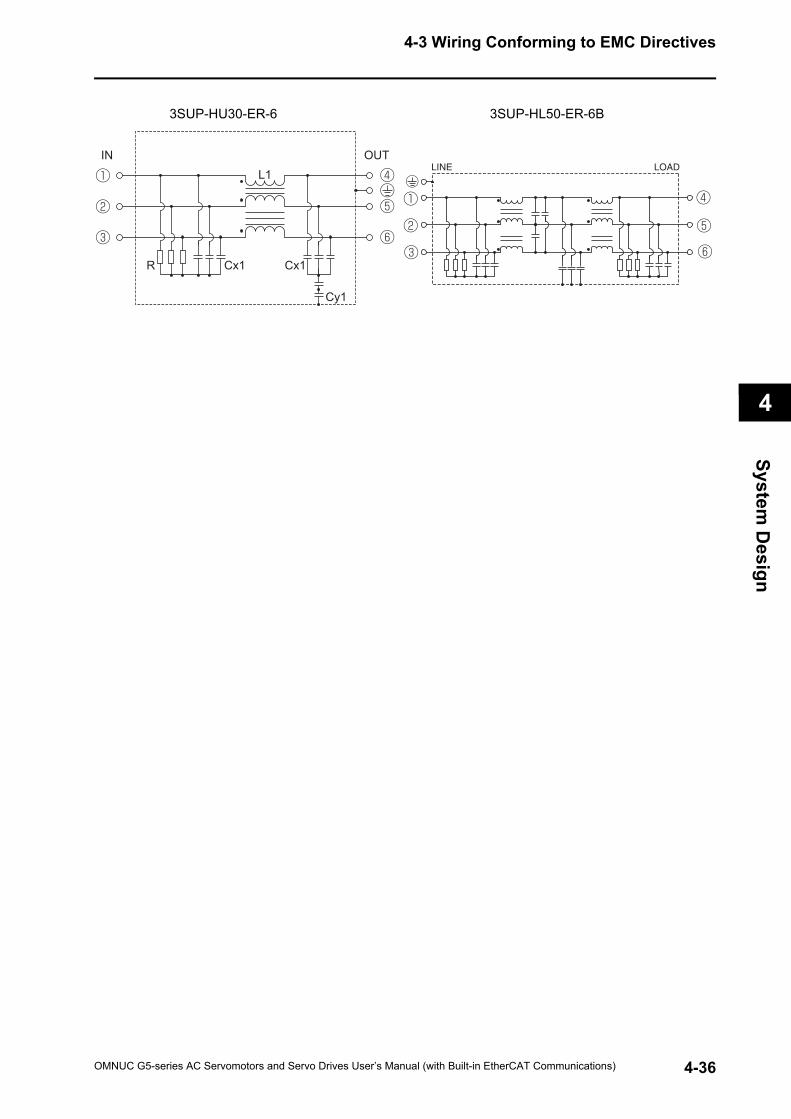
4-3 Wiring Conforming to EMC Directives
4
System D
esign
3SUP-HU30-ER-6 3SUP-HL50-ER-6B
Cx1Cx1R
L1
Cy1
OUTINLOADLINE
4-36OMNUC G5-series AC Servomotors and Servo Drives User’s Manual (with Built-in EtherCAT Communications)
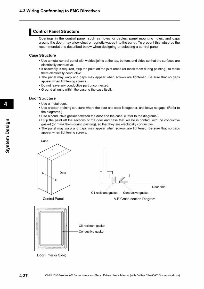
4-3 Wiring Conforming to EMC Directives
4
Syst
em D
esig
n
Control Panel StructureOpenings in the control panel, such as holes for cables, panel mounting holes, and gapsaround the door, may allow electromagnetic waves into the panel. To prevent this, observe therecommendations described below when designing or selecting a control panel.
Case StructureUse a metal control panel with welded joints at the top, bottom, and sides so that the surfaces areelectrically conductive.If assembly is required, strip the paint off the joint areas (or mask them during painting), to makethem electrically conductive.The panel may warp and gaps may appear when screws are tightened. Be sure that no gapsappear when tightening screws.Do not leave any conductive part unconnected.Ground all units within the case to the case itself.
Door StructureUse a metal door.Use a water-draining structure where the door and case fit together, and leave no gaps. (Refer tothe diagrams.)Use a conductive gasket between the door and the case. (Refer to the diagrams.)Strip the paint off the sections of the door and case that will be in contact with the conductivegasket (or mask them during painting), so that they are electrically conductive.The panel may warp and gaps may appear when screws are tightened. Be sure that no gapsappear when tightening screws.
Case
Door
Control Panel
Door (Interior Side)
A
B
A-B Cross-section Diagram
Oil-resistant gasket
Conductive gasket
Door side
Oil-resistant gasket Conductive gasket
4-37 OMNUC G5-series AC Servomotors and Servo Drives User’s Manual (with Built-in EtherCAT Communications)
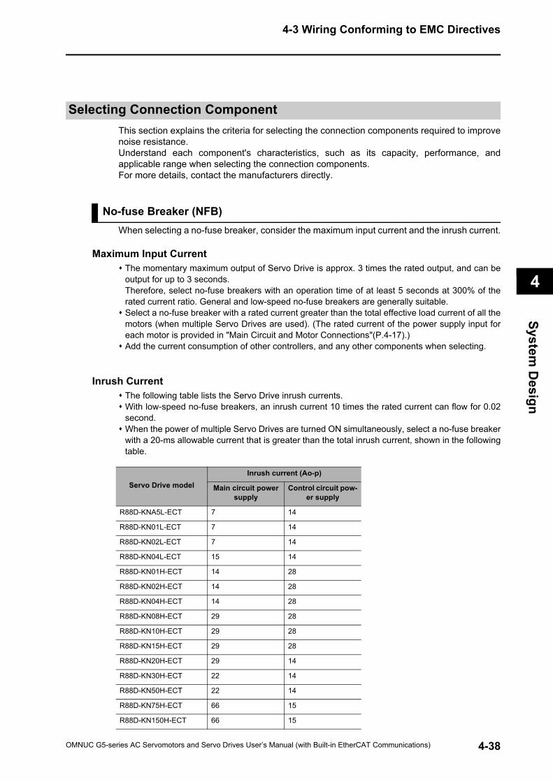
4-3 Wiring Conforming to EMC Directives
4
System D
esign
Selecting Connection ComponentThis section explains the criteria for selecting the connection components required to improvenoise resistance.Understand each component's characteristics, such as its capacity, performance, andapplicable range when selecting the connection components.For more details, contact the manufacturers directly.
No-fuse Breaker (NFB)When selecting a no-fuse breaker, consider the maximum input current and the inrush current.
Maximum Input CurrentThe momentary maximum output of Servo Drive is approx. 3 times the rated output, and can beoutput for up to 3 seconds.Therefore, select no-fuse breakers with an operation time of at least 5 seconds at 300% of therated current ratio. General and low-speed no-fuse breakers are generally suitable.Select a no-fuse breaker with a rated current greater than the total effective load current of all themotors (when multiple Servo Drives are used). (The rated current of the power supply input foreach motor is provided in "Main Circuit and Motor Connections"(P.4-17).)Add the current consumption of other controllers, and any other components when selecting.
Inrush CurrentThe following table lists the Servo Drive inrush currents.With low-speed no-fuse breakers, an inrush current 10 times the rated current can flow for 0.02second.When the power of multiple Servo Drives are turned ON simultaneously, select a no-fuse breakerwith a 20-ms allowable current that is greater than the total inrush current, shown in the followingtable.
Servo Drive modelInrush current (Ao-p)
Main circuit power supply
Control circuit pow-er supply
R88D-KNA5L-ECT 7 14
R88D-KN01L-ECT 7 14
R88D-KN02L-ECT 7 14
R88D-KN04L-ECT 15 14
R88D-KN01H-ECT 14 28
R88D-KN02H-ECT 14 28
R88D-KN04H-ECT 14 28
R88D-KN08H-ECT 29 28
R88D-KN10H-ECT 29 28
R88D-KN15H-ECT 29 28
R88D-KN20H-ECT 29 14
R88D-KN30H-ECT 22 14
R88D-KN50H-ECT 22 14
R88D-KN75H-ECT 66 15
R88D-KN150H-ECT 66 15
4-38OMNUC G5-series AC Servomotors and Servo Drives User’s Manual (with Built-in EtherCAT Communications)
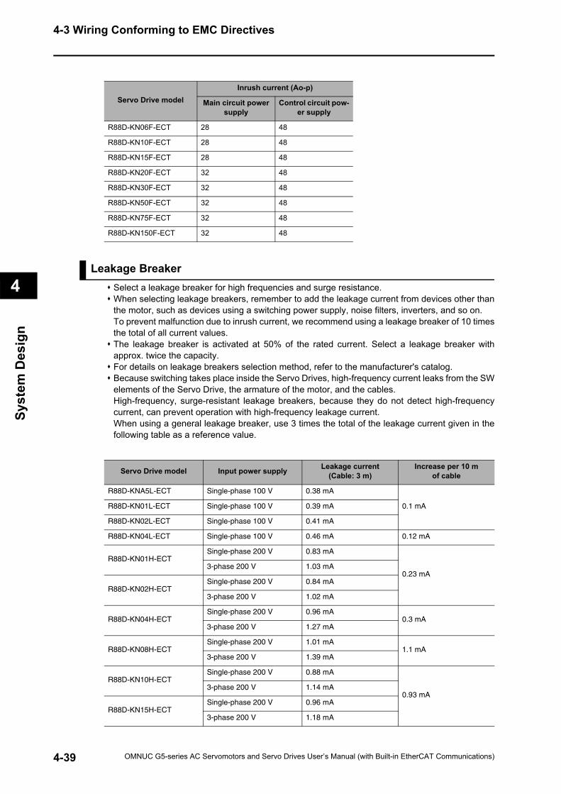
4-3 Wiring Conforming to EMC Directives
4
Syst
em D
esig
n
Leakage BreakerSelect a leakage breaker for high frequencies and surge resistance.When selecting leakage breakers, remember to add the leakage current from devices other thanthe motor, such as devices using a switching power supply, noise filters, inverters, and so on.To prevent malfunction due to inrush current, we recommend using a leakage breaker of 10 timesthe total of all current values.The leakage breaker is activated at 50% of the rated current. Select a leakage breaker withapprox. twice the capacity.For details on leakage breakers selection method, refer to the manufacturer's catalog.Because switching takes place inside the Servo Drives, high-frequency current leaks from the SWelements of the Servo Drive, the armature of the motor, and the cables.High-frequency, surge-resistant leakage breakers, because they do not detect high-frequencycurrent, can prevent operation with high-frequency leakage current.When using a general leakage breaker, use 3 times the total of the leakage current given in thefollowing table as a reference value.
Servo Drive modelInrush current (Ao-p)
Main circuit power supply
Control circuit pow-er supply
R88D-KN06F-ECT 28 48
R88D-KN10F-ECT 28 48
R88D-KN15F-ECT 28 48
R88D-KN20F-ECT 32 48
R88D-KN30F-ECT 32 48
R88D-KN50F-ECT 32 48
R88D-KN75F-ECT 32 48
R88D-KN150F-ECT 32 48
Servo Drive model Input power supply Leakage current (Cable: 3 m)
Increase per 10 m of cable
R88D-KNA5L-ECT Single-phase 100 V 0.38 mA
0.1 mAR88D-KN01L-ECT Single-phase 100 V 0.39 mA
R88D-KN02L-ECT Single-phase 100 V 0.41 mA
R88D-KN04L-ECT Single-phase 100 V 0.46 mA 0.12 mA
R88D-KN01H-ECTSingle-phase 200 V 0.83 mA
0.23 mA3-phase 200 V 1.03 mA
R88D-KN02H-ECTSingle-phase 200 V 0.84 mA
3-phase 200 V 1.02 mA
R88D-KN04H-ECTSingle-phase 200 V 0.96 mA
0.3 mA3-phase 200 V 1.27 mA
R88D-KN08H-ECTSingle-phase 200 V 1.01 mA
1.1 mA3-phase 200 V 1.39 mA
R88D-KN10H-ECTSingle-phase 200 V 0.88 mA
0.93 mA3-phase 200 V 1.14 mA
R88D-KN15H-ECTSingle-phase 200 V 0.96 mA
3-phase 200 V 1.18 mA
4-39 OMNUC G5-series AC Servomotors and Servo Drives User’s Manual (with Built-in EtherCAT Communications)
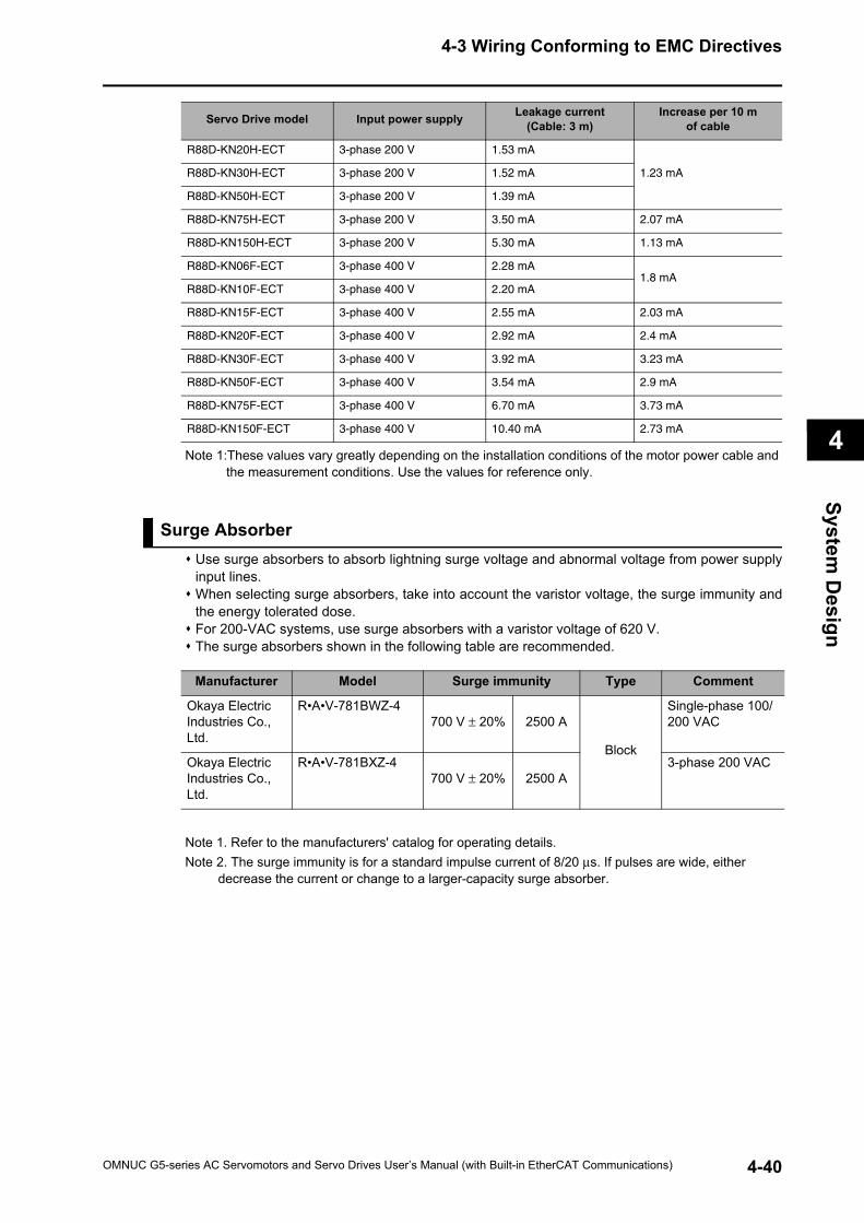
4-3 Wiring Conforming to EMC Directives
4
System D
esign
Note 1:These values vary greatly depending on the installation conditions of the motor power cable and the measurement conditions. Use the values for reference only.
Surge AbsorberUse surge absorbers to absorb lightning surge voltage and abnormal voltage from power supplyinput lines.When selecting surge absorbers, take into account the varistor voltage, the surge immunity andthe energy tolerated dose.For 200-VAC systems, use surge absorbers with a varistor voltage of 620 V.The surge absorbers shown in the following table are recommended.
Note 1. Refer to the manufacturers' catalog for operating details. Note 2. The surge immunity is for a standard impulse current of 8/20 µs. If pulses are wide, either
decrease the current or change to a larger-capacity surge absorber.
R88D-KN20H-ECT 3-phase 200 V 1.53 mA
1.23 mAR88D-KN30H-ECT 3-phase 200 V 1.52 mA
R88D-KN50H-ECT 3-phase 200 V 1.39 mA
R88D-KN75H-ECT 3-phase 200 V 3.50 mA 2.07 mA
R88D-KN150H-ECT 3-phase 200 V 5.30 mA 1.13 mA
R88D-KN06F-ECT 3-phase 400 V 2.28 mA1.8 mA
R88D-KN10F-ECT 3-phase 400 V 2.20 mA
R88D-KN15F-ECT 3-phase 400 V 2.55 mA 2.03 mA
R88D-KN20F-ECT 3-phase 400 V 2.92 mA 2.4 mA
R88D-KN30F-ECT 3-phase 400 V 3.92 mA 3.23 mA
R88D-KN50F-ECT 3-phase 400 V 3.54 mA 2.9 mA
R88D-KN75F-ECT 3-phase 400 V 6.70 mA 3.73 mA
R88D-KN150F-ECT 3-phase 400 V 10.40 mA 2.73 mA
Servo Drive model Input power supply Leakage current (Cable: 3 m)
Increase per 10 m of cable
Manufacturer Model Surge immunity Type Comment
Okaya Electric Industries Co., Ltd.
R•A•V-781BWZ-4700 V ± 20% 2500 A
Block
Single-phase 100/200 VAC
Okaya Electric Industries Co., Ltd.
R•A•V-781BXZ-4700 V ± 20% 2500 A
3-phase 200 VAC
4-40OMNUC G5-series AC Servomotors and Servo Drives User’s Manual (with Built-in EtherCAT Communications)
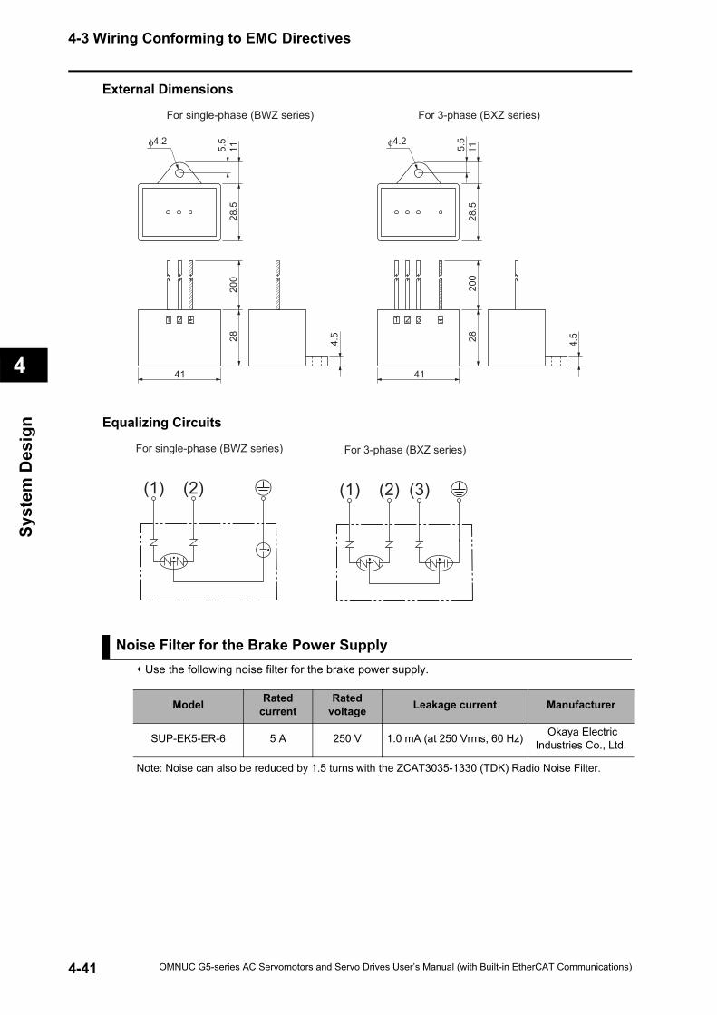
4-3 Wiring Conforming to EMC Directives
4
Syst
em D
esig
n
External Dimensions
Equalizing Circuits
Noise Filter for the Brake Power SupplyUse the following noise filter for the brake power supply.
Note: Noise can also be reduced by 1.5 turns with the ZCAT3035-1330 (TDK) Radio Noise Filter.
1 2 3
28 4.5
28.5
115.5φ4.2
41
200
For 3-phase (BXZ series)For single-phase (BWZ series)
21
28 4.5
28.5
115.5φ4.2
41
200
(1) (2) (3)
For 3-phase (BXZ series)For single-phase (BWZ series)
(1) (2)
Model Rated current
Rated voltage Leakage current Manufacturer
SUP-EK5-ER-6 5 A 250 V 1.0 mA (at 250 Vrms, 60 Hz) Okaya Electric Industries Co., Ltd.
4-41 OMNUC G5-series AC Servomotors and Servo Drives User’s Manual (with Built-in EtherCAT Communications)
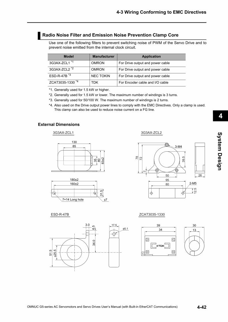
4-3 Wiring Conforming to EMC Directives
4
System D
esign
Radio Noise Filter and Emission Noise Prevention Clamp CoreUse one of the following filters to prevent switching noise of PWM of the Servo Drive and toprevent noise emitted from the internal clock circuit.
*1. Generally used for 1.5 kW or higher.*2. Generally used for 1.5 kW or lower. The maximum number of windings is 3 turns.*3. Generally used for 50/100 W. The maximum number of windings is 2 turns.*4. Also used on the Drive output power lines to comply with the EMC Directives. Only a clamp is used.
This clamp can also be used to reduce noise current on a FG line.
External Dimensions
Model Manufacturer Application
3G3AX-ZCL1 *1 OMRON For Drive output and power cable
3G3AX-ZCL2 *2 OMRON For Drive output and power cable
ESD-R-47B *3 NEC TOKIN For Drive output and power cable
ZCAT3035-1330 *4 TDK For Encoder cable and I/O cable
2-M5
3-M4
9526
78
80
12.5
72
50
7
39.5
3G3AX-ZCL23G3AX-ZCL1
51.5
φ25.
5
17.5φ5.1
3.0
6.5
34.0
ESD-R-47B
34 133039
ZCAT3035-1330
83±235
31.5
80
13085
180±2160±2
7×14 Long hole φ7
4-42OMNUC G5-series AC Servomotors and Servo Drives User’s Manual (with Built-in EtherCAT Communications)
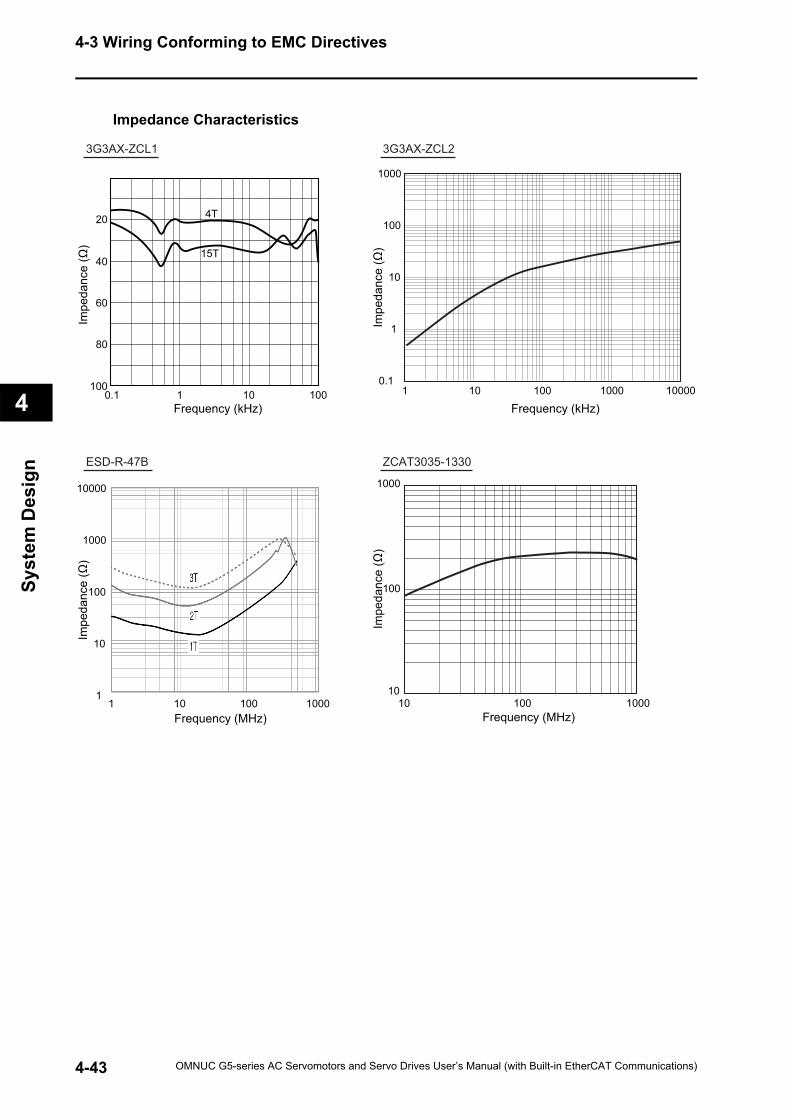
4-3 Wiring Conforming to EMC Directives
4
Syst
em D
esig
n
Impedance Characteristics
10 100 10000
1000
100
10
1
0.1
Frequency (kHz)Frequency (kHz)
Impe
danc
e (Ω
)
Impe
danc
e (Ω
)
1 1000
3G3AX-ZCL23G3AX-ZCL1
10000
1000
100
10
1
Impe
danc
e (Ω
)
10 100Frequency (MHz)
1 1000
ESD-R-47B ZCAT3035-1330
10 100Frequency (MHz)
1000
1000
100
10
Impe
danc
e (Ω
)
20
40
60
80
1001 10 1000.1
4T
15T
4-43 OMNUC G5-series AC Servomotors and Servo Drives User’s Manual (with Built-in EtherCAT Communications)
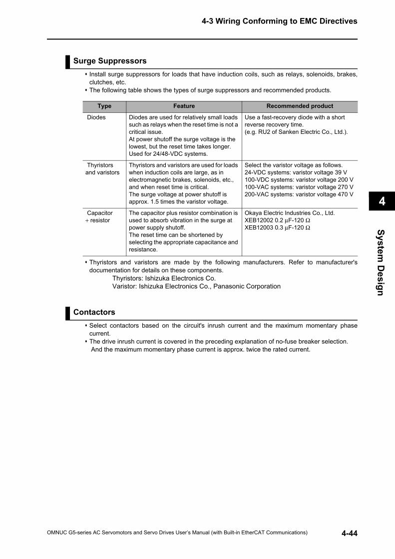
4-3 Wiring Conforming to EMC Directives
4
System D
esign
Surge SuppressorsInstall surge suppressors for loads that have induction coils, such as relays, solenoids, brakes,clutches, etc.The following table shows the types of surge suppressors and recommended products.
Thyristors and varistors are made by the following manufacturers. Refer to manufacturer'sdocumentation for details on these components.
Thyristors: Ishizuka Electronics Co. Varistor: Ishizuka Electronics Co., Panasonic Corporation
ContactorsSelect contactors based on the circuit's inrush current and the maximum momentary phasecurrent.The drive inrush current is covered in the preceding explanation of no-fuse breaker selection. And the maximum momentary phase current is approx. twice the rated current.
Type Feature Recommended product
Diodes Diodes are used for relatively small loads such as relays when the reset time is not a critical issue.At power shutoff the surge voltage is the lowest, but the reset time takes longer.Used for 24/48-VDC systems.
Use a fast-recovery diode with a short reverse recovery time.(e.g. RU2 of Sanken Electric Co., Ltd.).
Thyristors and varistors
Thyristors and varistors are used for loads when induction coils are large, as in electromagnetic brakes, solenoids, etc., and when reset time is critical.The surge voltage at power shutoff is approx. 1.5 times the varistor voltage.
Select the varistor voltage as follows.24-VDC systems: varistor voltage 39 V 100-VDC systems: varistor voltage 200 V 100-VAC systems: varistor voltage 270 V 200-VAC systems: varistor voltage 470 V
Capacitor + resistor
The capacitor plus resistor combination is used to absorb vibration in the surge at power supply shutoff.The reset time can be shortened by selecting the appropriate capacitance and resistance.
Okaya Electric Industries Co., Ltd. XEB12002 0.2 µF-120 Ω XEB12003 0.3 µF-120 Ω
4-44OMNUC G5-series AC Servomotors and Servo Drives User’s Manual (with Built-in EtherCAT Communications)
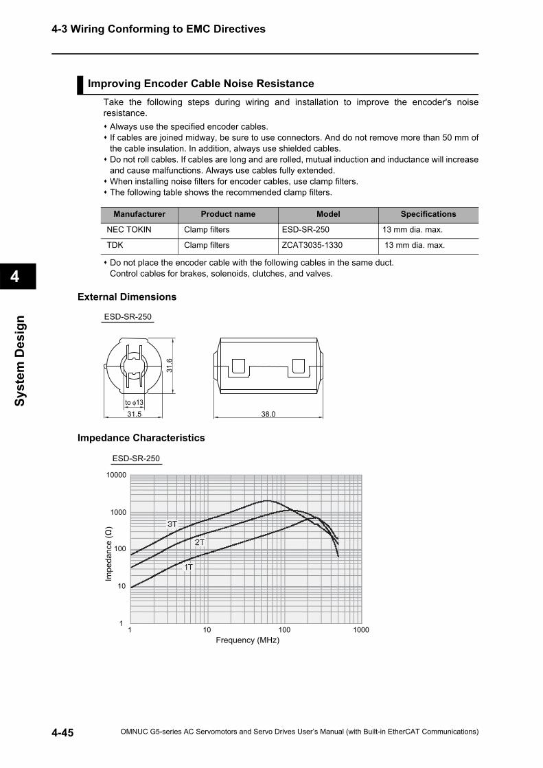
4-3 Wiring Conforming to EMC Directives
4
Syst
em D
esig
n
Improving Encoder Cable Noise ResistanceTake the following steps during wiring and installation to improve the encoder's noiseresistance.
Always use the specified encoder cables.If cables are joined midway, be sure to use connectors. And do not remove more than 50 mm ofthe cable insulation. In addition, always use shielded cables.Do not roll cables. If cables are long and are rolled, mutual induction and inductance will increaseand cause malfunctions. Always use cables fully extended.When installing noise filters for encoder cables, use clamp filters.The following table shows the recommended clamp filters.
Do not place the encoder cable with the following cables in the same duct.Control cables for brakes, solenoids, clutches, and valves.
External Dimensions
Impedance Characteristics
Manufacturer Product name Model Specifications
NEC TOKIN Clamp filters ESD-SR-250 13 mm dia. max.
TDK Clamp filters ZCAT3035-1330 13 mm dia. max.
31.5to φ13
31.6
38.0
ESD-SR-250
10000
1000
100
10
1
Impe
danc
e (Ω
)
10 100Frequency (MHz)
1 1000
ESD-SR-250
4-45 OMNUC G5-series AC Servomotors and Servo Drives User’s Manual (with Built-in EtherCAT Communications)
4-3 Wiring Conforming to EMC Directives
4
System D
esign
Improving Control I/O Signal Noise ResistancePositioning can be affected and I/O signal errors can occur if control I/O is influenced by noise.
Use completely separate power supplies for the control power supply (especially 24 VDC) and theexternal operation power supply. In particular, do not connect the 2 power supply ground wires.Install a noise filter on the primary side of the control power supply.If motors with brakes are being used, do not use the same 24-VDC power supply for both thebrakes and the control I/O. Additionally, do not connect the ground wires. Connecting the groundwires may cause I/O signal errors.If the control power supply wiring is long, noise resistance can be improved by adding 1-µFlaminated ceramic capacitors between the control power supply and ground at the drive inputsection or the controller output section.
Reactor to Reduce Harmonic Current
Harmonic Current MeasuresUse a Reactor to suppress harmonic currents. The Reactor functions to suppress sudden andquick changes in electric currents.The Guidelines for Suppressing Harmonic Currents in Home Appliances and General PurposeComponents requires that manufacturers take appropriate remedies to suppress harmoniccurrent emissions onto power supply lines.Select the proper Reactor model according to the Servo Drive to be used.
4-46OMNUC G5-series AC Servomotors and Servo Drives User’s Manual (with Built-in EtherCAT Communications)
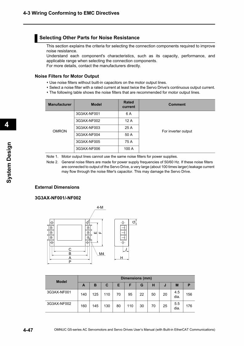
4-3 Wiring Conforming to EMC Directives
4
Syst
em D
esig
n
Selecting Other Parts for Noise ResistanceThis section explains the criteria for selecting the connection components required to improvenoise resistance.Understand each component's characteristics, such as its capacity, performance, andapplicable range when selecting the connection components.For more details, contact the manufacturers directly.
Noise Filters for Motor OutputUse noise filters without built-in capacitors on the motor output lines.Select a noise filter with a rated current at least twice the Servo Drive's continuous output current.The following table shows the noise filters that are recommended for motor output lines.
Note 1. Motor output lines cannot use the same noise filters for power supplies.Note 2. General noise filters are made for power supply frequencies of 50/60 Hz. If these noise filters
are connected to output of the Servo Drive, a very large (about 100 times larger) leakage current may flow through the noise filter's capacitor. This may damage the Servo Drive.
External Dimensions
3G3AX-NF001/-NF002
Manufacturer Model Rated current Comment
OMRON
3G3AX-NF001 6 A
For inverter output
3G3AX-NF002 12 A
3G3AX-NF003 25 A
3G3AX-NF004 50 A
3G3AX-NF005 75 A
3G3AX-NF006 100 A
4-M
M4CBAP
E F
J
H
G
ModelDimensions (mm)
A B C E F G H J M P
3G3AX-NF001 140 125 110 70 95 22 50 20 4.5 dia. 156
3G3AX-NF002 160 145 130 80 110 30 70 25 5.5 dia. 176
4-47 OMNUC G5-series AC Servomotors and Servo Drives User’s Manual (with Built-in EtherCAT Communications)
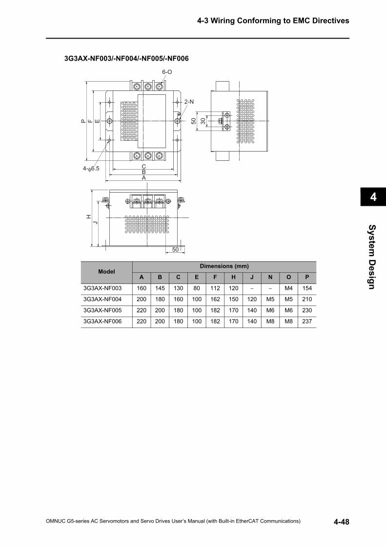
4-3 Wiring Conforming to EMC Directives
4
System D
esign
3G3AX-NF003/-NF004/-NF005/-NF006
CBA
P F E
6-O
2-N
50 30
4-φ6.5
50
HJ
ModelDimensions (mm)
A B C E F H J N O P
3G3AX-NF003 160 145 130 80 112 120 − − M4 154
3G3AX-NF004 200 180 160 100 162 150 120 M5 M5 210
3G3AX-NF005 220 200 180 100 182 170 140 M6 M6 230
3G3AX-NF006 220 200 180 100 182 170 140 M8 M8 237
4-48OMNUC G5-series AC Servomotors and Servo Drives User’s Manual (with Built-in EtherCAT Communications)
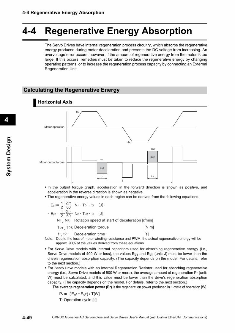
4-4 Regenerative Energy Absorption
4
Syst
em D
esig
n
4-4 Regenerative Energy AbsorptionThe Servo Drives have internal regeneration process circuitry, which absorbs the regenerativeenergy produced during motor deceleration and prevents the DC voltage from increasing. Anovervoltage error occurs, however, if the amount of regenerative energy from the motor is toolarge. If this occurs, remedies must be taken to reduce the regenerative energy by changingoperating patterns, or to increase the regeneration process capacity by connecting an ExternalRegeneration Unit.
Calculating the Regenerative Energy
Horizontal Axis
In the output torque graph, acceleration in the forward direction is shown as positive, andacceleration in the reverse direction is shown as negative.The regenerative energy values in each region can be derived from the following equations.
Note: Due to the loss of motor winding resistance and PWM, the actual regenerative energy will be approx. 90% of the values derived from these equations.
For Servo Drive models with internal capacitors used for absorbing regenerative energy (i.e.,Servo Drive models of 400 W or less), the values Eg1 and Eg2 (unit: J) must be lower than thedrive's regeneration absorption capacity. (The capacity depends on the model. For details, referto the next section.)For Servo Drive models with an Internal Regeneration Resistor used for absorbing regenerativeenergy (i.e., Servo Drive models of 500 W or more), the average amount of regeneration Pr (unit:W) must be calculated, and this value must be lower than the drive's regeneration absorptioncapacity. (The capacity depends on the model. For details, refer to the next section.)
The average regeneration power (Pr) is the regeneration power produced in 1 cycle of operation [W].
Motor operation
Motor output torque
+N1
−N2
TD1
TD2
t 1 t 2
T
Eg1Eg1
Eg2Eg2
N1 , N2: Rotation speed at start of deceleration [r/min]
Deceleration torque [N·m]
Deceleration time [s]
TD1 , TD2:t1, t2:
2Eg1Eg=Pr ( + ) / T[W]T: Operation cycle [s]
4-49 OMNUC G5-series AC Servomotors and Servo Drives User’s Manual (with Built-in EtherCAT Communications)
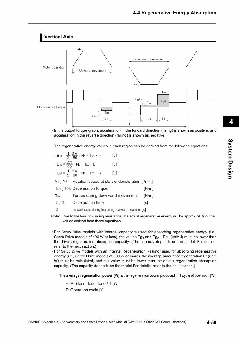
4-4 Regenerative Energy Absorption
4
System D
esign
Vertical Axis
In the output torque graph, acceleration in the forward direction (rising) is shown as positive, andacceleration in the reverse direction (falling) is shown as negative.
The regenerative energy values in each region can be derived from the following equations.
Note: Due to the loss of winding resistance, the actual regenerative energy will be approx. 90% of the values derived from these equations.
For Servo Drive models with internal capacitors used for absorbing regenerative energy (i.e.,Servo Drive models of 400 W or less), the values Eg1 and Eg2 + Eg3 (unit: J) must be lower thanthe drive's regeneration absorption capacity. (The capacity depends on the model. For details,refer to the next section.)For Servo Drive models with an Internal Regeneration Resistor used for absorbing regenerativeenergy (i.e., Servo Drive models of 500 W or more), the average amount of regeneration Pr (unit:W) must be calculated, and this value must be lower than the drive's regeneration absorptioncapacity. (The capacity depends on the model.For details, refer to the next section.)
The average regeneration power (Pr) is the regeneration power produced in 1 cycle of operation [W].
Motor operation
Motor output torque
+N1
−N2
t 1 t 2 t 3
T
Eg1
Eg3Eg3
Upward movement
Downward movement
TD2
TL2
TD1
Eg2
N1 , N2: Rotation speed at start of deceleration [r/min]
Deceleration torque [N·m]
Torque during downward movement [N·m]
Deceleration time [s]
Constant-speed driving time during downward movement [s]
TD1 , TD2:
t1, t3:
TL2:
t2:
2Eg1Eg=Pr ( + ) / T [W]T: Operation cycle [s]
3Eg+
4-50OMNUC G5-series AC Servomotors and Servo Drives User’s Manual (with Built-in EtherCAT Communications)
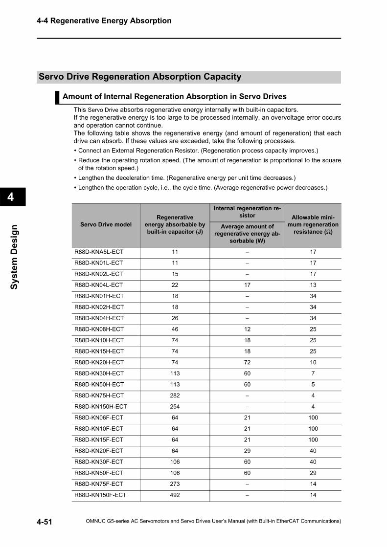
4-4 Regenerative Energy Absorption
4
Syst
em D
esig
n
Servo Drive Regeneration Absorption Capacity
Amount of Internal Regeneration Absorption in Servo DrivesThis Servo Drive absorbs regenerative energy internally with built-in capacitors.If the regenerative energy is too large to be processed internally, an overvoltage error occursand operation cannot continue.The following table shows the regenerative energy (and amount of regeneration) that eachdrive can absorb. If these values are exceeded, take the following processes.
Connect an External Regeneration Resistor. (Regeneration process capacity improves.)Reduce the operating rotation speed. (The amount of regeneration is proportional to the squareof the rotation speed.)Lengthen the deceleration time. (Regenerative energy per unit time decreases.)Lengthen the operation cycle, i.e., the cycle time. (Average regenerative power decreases.)
Servo Drive modelRegenerative
energy absorbable by built-in capacitor (J)
Internal regeneration re-sistor Allowable mini-
mum regenerationresistance (Ω)
Average amount of regenerative energy ab-
sorbable (W)
R88D-KNA5L-ECT 11 − 17
R88D-KN01L-ECT 11 − 17
R88D-KN02L-ECT 15 − 17
R88D-KN04L-ECT 22 17 13
R88D-KN01H-ECT 18 − 34
R88D-KN02H-ECT 18 − 34
R88D-KN04H-ECT 26 − 34
R88D-KN08H-ECT 46 12 25
R88D-KN10H-ECT 74 18 25
R88D-KN15H-ECT 74 18 25
R88D-KN20H-ECT 74 72 10
R88D-KN30H-ECT 113 60 7
R88D-KN50H-ECT 113 60 5
R88D-KN75H-ECT 282 − 4
R88D-KN150H-ECT 254 − 4
R88D-KN06F-ECT 64 21 100
R88D-KN10F-ECT 64 21 100
R88D-KN15F-ECT 64 21 100
R88D-KN20F-ECT 64 29 40
R88D-KN30F-ECT 106 60 40
R88D-KN50F-ECT 106 60 29
R88D-KN75F-ECT 273 − 14
R88D-KN150F-ECT 492 − 14
4-51 OMNUC G5-series AC Servomotors and Servo Drives User’s Manual (with Built-in EtherCAT Communications)
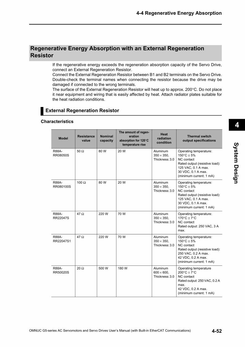
4-4 Regenerative Energy Absorption
4
System D
esign
Regenerative Energy Absorption with an External Regeneration Resistor
If the regenerative energy exceeds the regeneration absorption capacity of the Servo Drive,connect an External Regeneration Resistor.Connect the External Regeneration Resistor between B1 and B2 terminals on the Servo Drive.Double-check the terminal names when connecting the resistor because the drive may bedamaged if connected to the wrong terminals.The surface of the External Regeneration Resistor will heat up to approx. 200°C. Do not placeit near equipment and wiring that is easily affected by heat. Attach radiator plates suitable forthe heat radiation conditions.
External Regeneration Resistor
Characteristics
Model Resistance value
Nominal capacity
The amount of regen-eration
absorption for 120°C temperature rise
Heat radiation condition
Thermal switch output specifications
R88A-RR08050S
50 Ω 80 W 20 W Aluminum 350 × 350, Thickness: 3.0
Operating temperature: 150°C ± 5%NC contactRated output (resistive load):125 VAC, 0.1 A max. 30 VDC, 0.1 A max. (minimum current: 1 mA)
R88A-RR080100S
100 Ω 80 W 20 W Aluminum 350 × 350, Thickness: 3.0
Operating temperature: 150°C ± 5%NC contactRated output (resistive load):125 VAC, 0.1 A max. 30 VDC, 0.1 A max. (minimum current: 1 mA)
R88A-RR22047S
47 Ω 220 W 70 W Aluminum 350 × 350, Thickness: 3.0
Operating temperature: 170°C ± 7°CNC contactRated output: 250 VAC, 3 A max.
R88A-RR22047S1
47 Ω 220 W 70 W Aluminum 350 × 350, Thickness: 3.0
Operating temperature: 150°C ± 5%NC contactRated output (resistive load):250 VAC, 0.2 A max. 42 VDC, 0.2 A max. (minimum current: 1 mA)
R88A-RR50020S
20 Ω 500 W 180 W Aluminum 600 × 600, Thickness: 3.0
Operating temperature 200°C ± 7°CNC contactRated output: 250 VAC, 0.2 A max.42 VDC, 0.2 A max.(minimum current: 1 mA)
4-52OMNUC G5-series AC Servomotors and Servo Drives User’s Manual (with Built-in EtherCAT Communications)
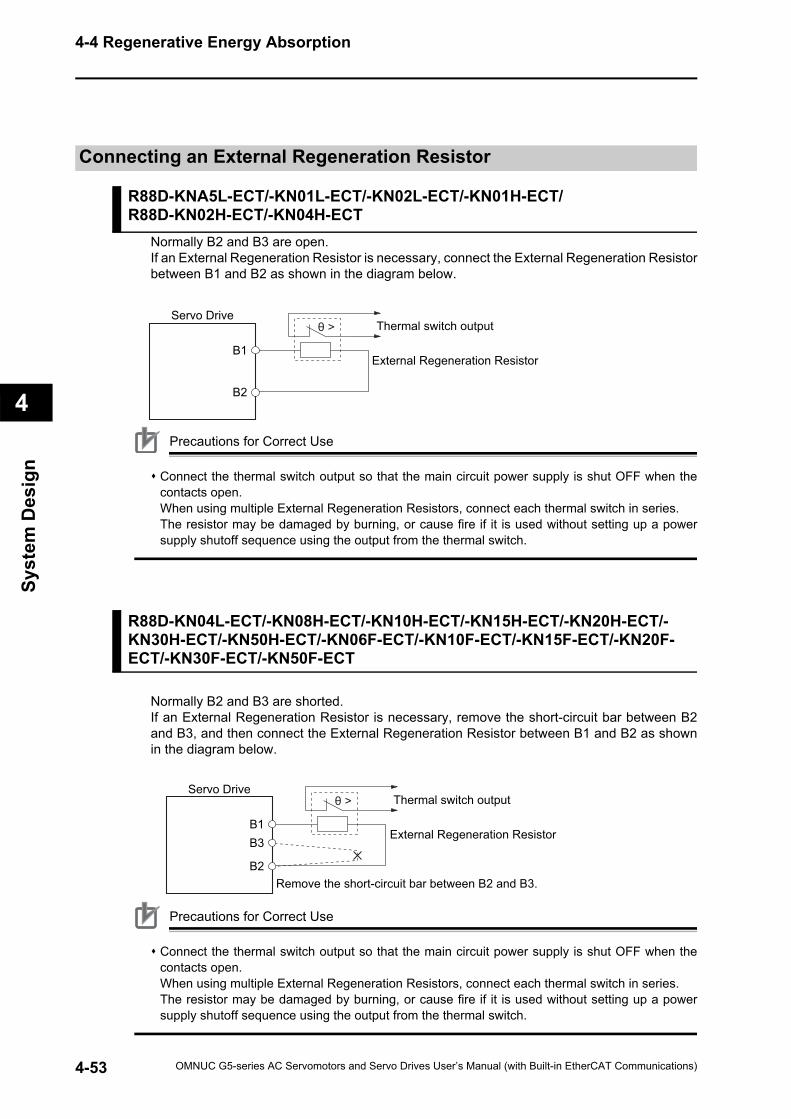
4-4 Regenerative Energy Absorption
4
Syst
em D
esig
n
Connecting an External Regeneration Resistor
R88D-KNA5L-ECT/-KN01L-ECT/-KN02L-ECT/-KN01H-ECT/R88D-KN02H-ECT/-KN04H-ECT
Normally B2 and B3 are open.If an External Regeneration Resistor is necessary, connect the External Regeneration Resistorbetween B1 and B2 as shown in the diagram below.
Precautions for Correct Use
Connect the thermal switch output so that the main circuit power supply is shut OFF when thecontacts open.When using multiple External Regeneration Resistors, connect each thermal switch in series.The resistor may be damaged by burning, or cause fire if it is used without setting up a powersupply shutoff sequence using the output from the thermal switch.
R88D-KN04L-ECT/-KN08H-ECT/-KN10H-ECT/-KN15H-ECT/-KN20H-ECT/-KN30H-ECT/-KN50H-ECT/-KN06F-ECT/-KN10F-ECT/-KN15F-ECT/-KN20F-ECT/-KN30F-ECT/-KN50F-ECT
Normally B2 and B3 are shorted.If an External Regeneration Resistor is necessary, remove the short-circuit bar between B2and B3, and then connect the External Regeneration Resistor between B1 and B2 as shownin the diagram below.
Precautions for Correct Use
Connect the thermal switch output so that the main circuit power supply is shut OFF when thecontacts open.When using multiple External Regeneration Resistors, connect each thermal switch in series.The resistor may be damaged by burning, or cause fire if it is used without setting up a powersupply shutoff sequence using the output from the thermal switch.
Servo Drive
B1External Regeneration Resistor
θ > Thermal switch output
B2
Servo Drive
B1B3
External Regeneration Resistor
Remove the short-circuit bar between B2 and B3.
θ > Thermal switch output
B2
4-53 OMNUC G5-series AC Servomotors and Servo Drives User’s Manual (with Built-in EtherCAT Communications)
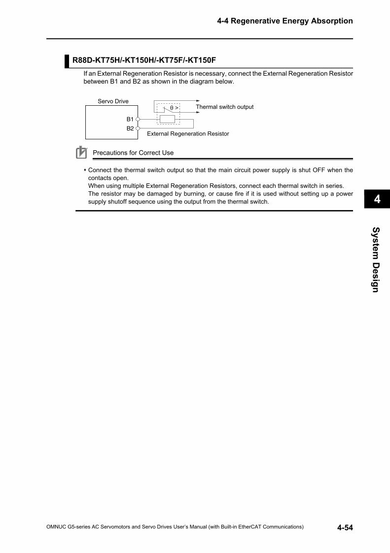
4-4 Regenerative Energy Absorption
4
System D
esign
R88D-KT75H/-KT150H/-KT75F/-KT150FIf an External Regeneration Resistor is necessary, connect the External Regeneration Resistorbetween B1 and B2 as shown in the diagram below.
Precautions for Correct Use
Connect the thermal switch output so that the main circuit power supply is shut OFF when thecontacts open.When using multiple External Regeneration Resistors, connect each thermal switch in series.The resistor may be damaged by burning, or cause fire if it is used without setting up a powersupply shutoff sequence using the output from the thermal switch.
B1
B2
Servo Drive
External Regeneration Resistor
Thermal switch outputθ >
4-54OMNUC G5-series AC Servomotors and Servo Drives User’s Manual (with Built-in EtherCAT Communications)
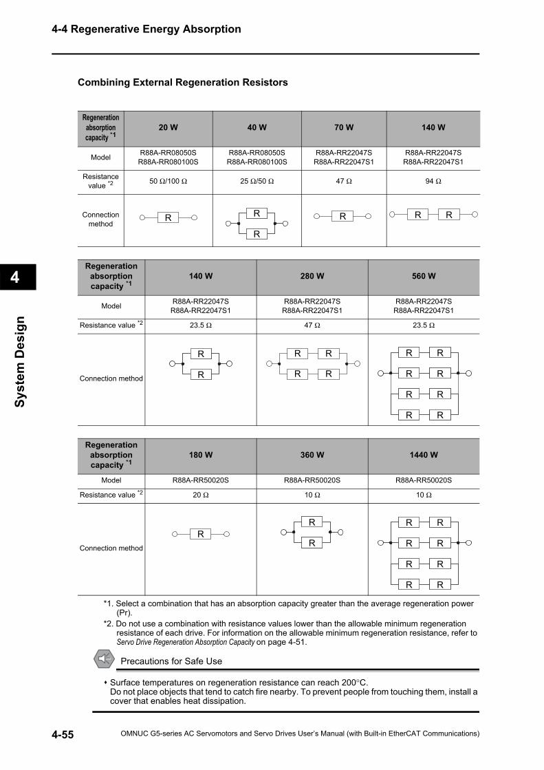
4-4 Regenerative Energy Absorption
4
Syst
em D
esig
n
Combining External Regeneration Resistors
*1. Select a combination that has an absorption capacity greater than the average regeneration power (Pr).
*2. Do not use a combination with resistance values lower than the allowable minimum regeneration resistance of each drive. For information on the allowable minimum regeneration resistance, refer to Servo Drive Regeneration Absorption Capacity on page 4-51.
Precautions for Safe Use
Surface temperatures on regeneration resistance can reach 200°C. Do not place objects that tend to catch fire nearby. To prevent people from touching them, install a cover that enables heat dissipation.
Regeneration absorption capacity *1
20 W 40 W 70 W 140 W
Model R88A-RR08050S R88A-RR080100S
R88A-RR08050S R88A-RR080100S
R88A-RR22047SR88A-RR22047S1
R88A-RR22047SR88A-RR22047S1
Resistance value *2 50 Ω/100 Ω 25 Ω/50 Ω 47 Ω 94 Ω
Connection method
R
R
R
R
R R R R
Regeneration absorption capacity *1
140 W 280 W 560 W
Model R88A-RR22047SR88A-RR22047S1
R88A-RR22047SR88A-RR22047S1
R88A-RR22047SR88A-RR22047S1
Resistance value *2 23.5 Ω 47 Ω 23.5 Ω
Connection method R
R
R
R
R R
R R
R R
R R
R R
R R
R R
R R
R R
R R
Regeneration absorption capacity *1
180 W 360 W 1440 W
Model R88A-RR50020S R88A-RR50020S R88A-RR50020S
Resistance value *2 20 Ω 10 Ω 10 Ω
Connection method
RR
R
R
R
R R
R R
R R
R R
R R
R R
R R
R R
4-55 OMNUC G5-series AC Servomotors and Servo Drives User’s Manual (with Built-in EtherCAT Communications)
5
EtherCAT CommunicationsThis chapter describes EtherCAT communications under the assumption that theServo Drive is connected to a CJ1W-NC281/NC481/NC881/NCF81/NC482/NC882 Position Control Unit.
5-1 Display Area and Settings ...........................................5-15-2 Structure of the CAN
Application Protocol over EtherCAT ..........................5-35-3 EtherCAT State Machine ..............................................5-45-4 Process Data Objects (PDOs)......................................5-55-5 Service Data Objects (SDOs).......................................5-95-6 Synchronization with Distributed Clocks.................5-105-7 Emergency Messages ................................................5-11
OMNUC G5-series AC Servomotors and Servo Drives User’s Manual (with Built-in EtherCAT Communications)
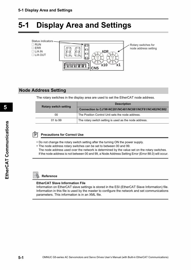
5-1 Display Area and Settings
5
Ethe
rCA
T C
omm
unic
atio
ns
5-1 Display Area and Settings
Node Address SettingThe rotary switches in the display area are used to set the EtherCAT node address.
Precautions for Correct Use
Do not change the rotary switch setting after the turning ON the power supply.The node address rotary switches can be set to between 00 and 99.The node address used over the network is determined by the value set on the rotary switches.If the node address is not between 00 and 99, a Node Address Setting Error (Error 88.0) will occur.
Reference
EtherCAT Slave Information FileInformation on EtherCAT slave settings is stored in the ESI (EtherCAT Slave Information) file.Information in this file is used by the master to configure the network and set communicationsparameters. This information is in an XML file.
CN5
ADR
x10 x1
Rotary switches for node address setting
Status indicators@ RUN@ ERR@ L/A IN@ L/A OUT
Rotary switch settingDescription
Connection to CJ1W-NC281/NC481/NC881/NCF81/NC482/NC882
00 The Position Control Unit sets the node address.
01 to 99 The rotary switch setting is used as the node address.
5-1 OMNUC G5-series AC Servomotors and Servo Drives User’s Manual (with Built-in EtherCAT Communications)
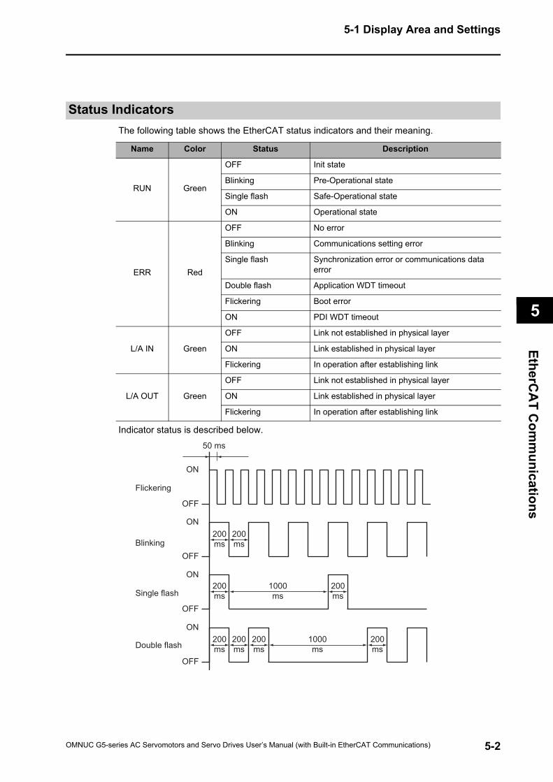
5-1 Display Area and Settings
5
EtherCA
T Com
munications
Status IndicatorsThe following table shows the EtherCAT status indicators and their meaning.
Indicator status is described below.
Name Color Status Description
RUN Green
OFF Init state
Blinking Pre-Operational state
Single flash Safe-Operational state
ON Operational state
ERR Red
OFF No error
Blinking Communications setting error
Single flash Synchronization error or communications data error
Double flash Application WDT timeout
Flickering Boot error
ON PDI WDT timeout
L/A IN Green
OFF Link not established in physical layer
ON Link established in physical layer
Flickering In operation after establishing link
L/A OUT Green
OFF Link not established in physical layer
ON Link established in physical layer
Flickering In operation after establishing link
50 ms
ON
OFF
200ms
200ms
200ms
1000ms
200ms
ON
OFF
200ms
1000ms
200ms
ON
OFF
200ms
200ms
ON
OFF
Flickering
Blinking
Single flash
Double flash
5-2OMNUC G5-series AC Servomotors and Servo Drives User’s Manual (with Built-in EtherCAT Communications)
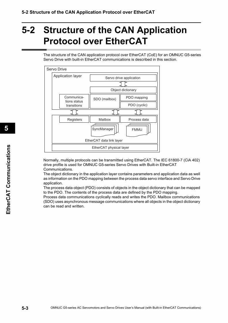
5-2 Structure of the CAN Application Protocol over EtherCAT
5
Ethe
rCA
T C
omm
unic
atio
ns
5-2 Structure of the CAN Application Protocol over EtherCATThe structure of the CAN application protocol over EtherCAT (CoE) for an OMNUC G5-seriesServo Drive with built-in EtherCAT communications is described in this section.
Normally, multiple protocols can be transmitted using EtherCAT. The IEC 61800-7 (CiA 402) drive profile is used for OMNUC G5-series Servo Drives with Built-in EtherCAT Communications. The object dictionary in the application layer contains parameters and application data as well as information on the PDO mapping between the process data servo interface and Servo Drive application.The process data object (PDO) consists of objects in the object dictionary that can be mapped to the PDO. The contents of the process data are defined by the PDO mapping.Process data communications cyclically reads and writes the PDO. Mailbox communications (SDO) uses asynchronous message communications where all objects in the object dictionary can be read and written.
Process dataMailboxRegisters
FMMUSyncManager
SDO (mailbox) PDO mapping
Object dictionary
PDO (cyclic)
Servo Drive
EtherCAT data link layer
EtherCAT physical layer
Application layer Servo drive application
Communica-tions status transitions
5-3 OMNUC G5-series AC Servomotors and Servo Drives User’s Manual (with Built-in EtherCAT Communications)
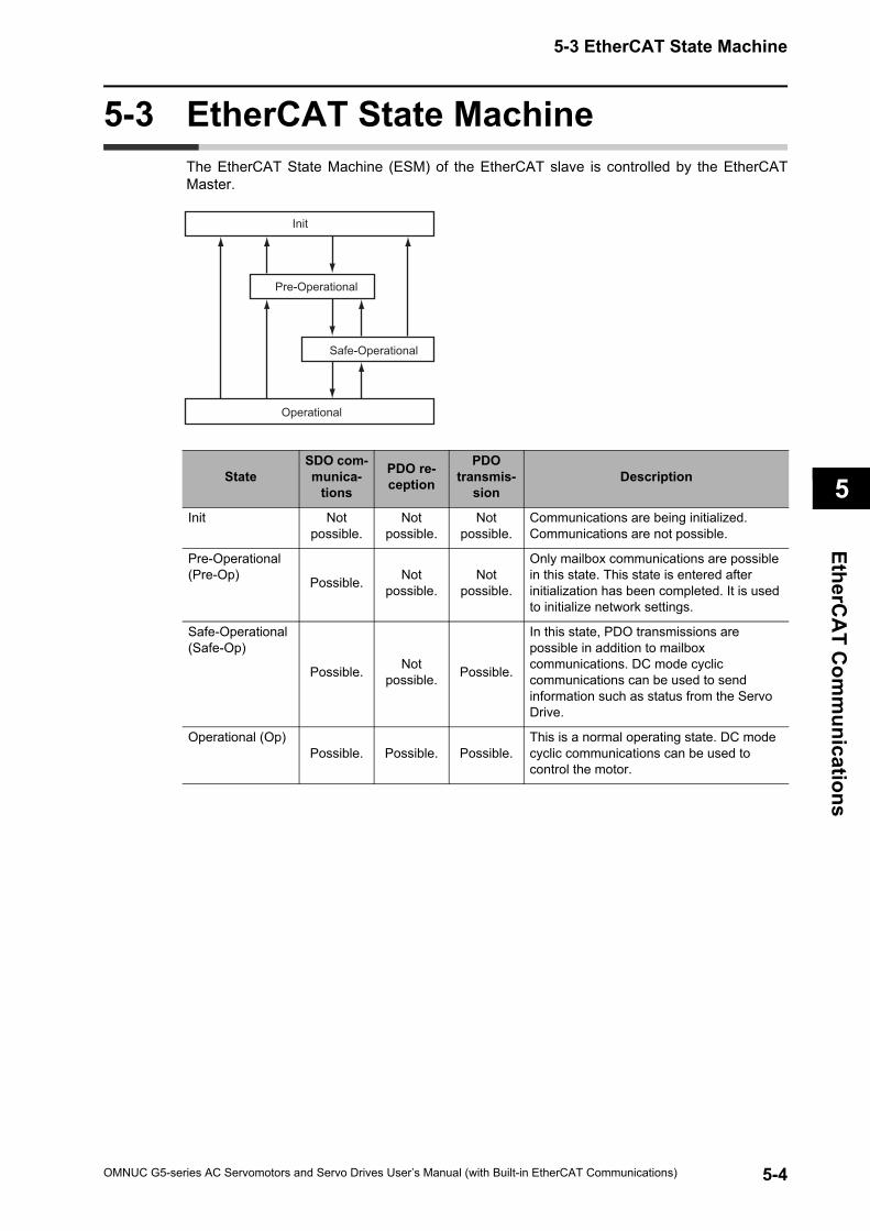
5-3 EtherCAT State Machine
5
EtherCA
T Com
munications
5-3 EtherCAT State MachineThe EtherCAT State Machine (ESM) of the EtherCAT slave is controlled by the EtherCATMaster.
Safe-Operational
Pre-Operational
Init
Operational
StateSDO com-munica-
tions
PDO re-ception
PDO transmis-
sionDescription
Init Not possible.
Not possible.
Not possible.
Communications are being initialized. Communications are not possible.
Pre-Operational (Pre-Op) Possible. Not
possible.Not
possible.
Only mailbox communications are possible in this state. This state is entered after initialization has been completed. It is used to initialize network settings.
Safe-Operational (Safe-Op)
Possible. Not possible. Possible.
In this state, PDO transmissions are possible in addition to mailbox communications. DC mode cyclic communications can be used to send information such as status from the Servo Drive.
Operational (Op)Possible. Possible. Possible.
This is a normal operating state. DC mode cyclic communications can be used to control the motor.
5-4OMNUC G5-series AC Servomotors and Servo Drives User’s Manual (with Built-in EtherCAT Communications)
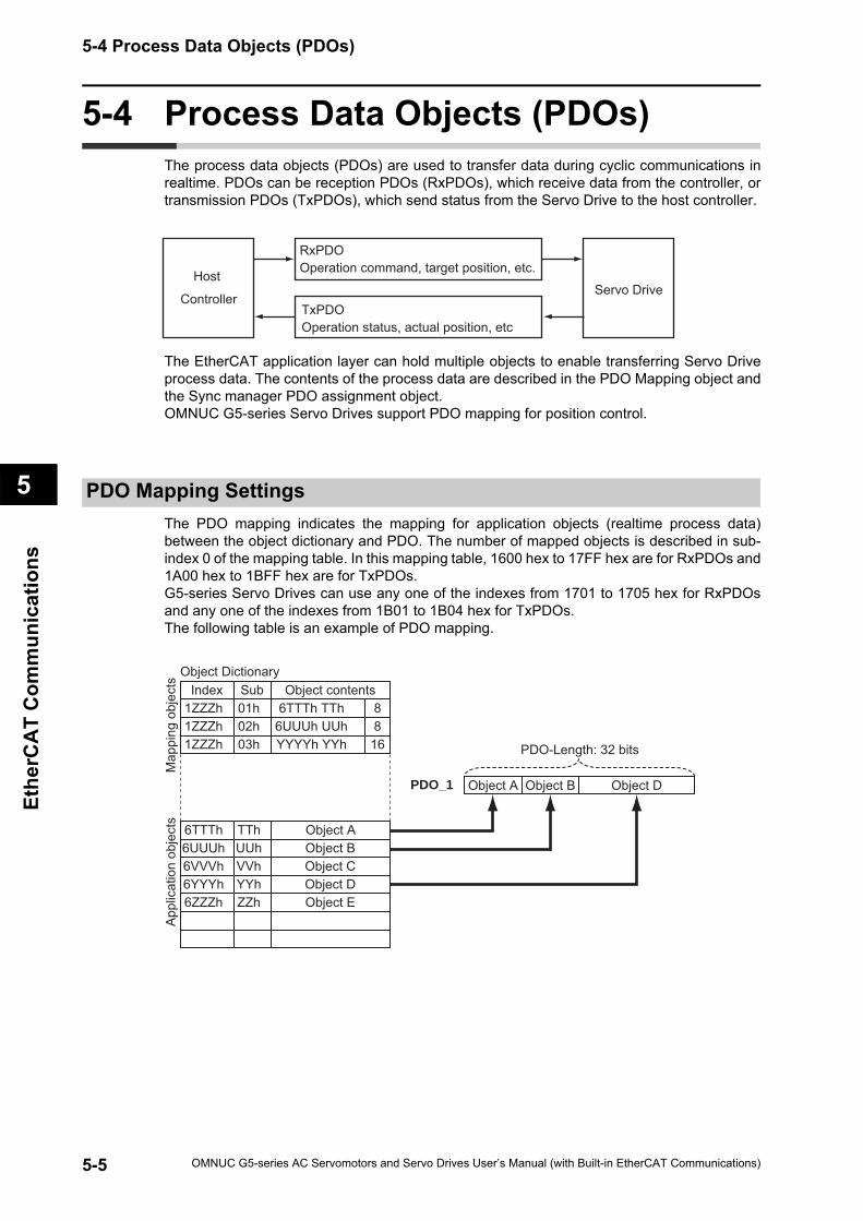
5-4 Process Data Objects (PDOs)
5
Ethe
rCA
T C
omm
unic
atio
ns
5-4 Process Data Objects (PDOs)The process data objects (PDOs) are used to transfer data during cyclic communications inrealtime. PDOs can be reception PDOs (RxPDOs), which receive data from the controller, ortransmission PDOs (TxPDOs), which send status from the Servo Drive to the host controller.
The EtherCAT application layer can hold multiple objects to enable transferring Servo Driveprocess data. The contents of the process data are described in the PDO Mapping object andthe Sync manager PDO assignment object.OMNUC G5-series Servo Drives support PDO mapping for position control.
PDO Mapping SettingsThe PDO mapping indicates the mapping for application objects (realtime process data)between the object dictionary and PDO. The number of mapped objects is described in sub-index 0 of the mapping table. In this mapping table, 1600 hex to 17FF hex are for RxPDOs and1A00 hex to 1BFF hex are for TxPDOs.G5-series Servo Drives can use any one of the indexes from 1701 to 1705 hex for RxPDOsand any one of the indexes from 1B01 to 1B04 hex for TxPDOs.The following table is an example of PDO mapping.
Host
ControllerServo Drive
RxPDO Operation command, target position, etc.
TxPDO Operation status, actual position, etc
6TTTh
ZZh
Index Sub
6UUUh UUh16
Object contents1ZZZh1ZZZh1ZZZh
01h02h03h
6TTTh TTh
YYYYh YYh
88
6UUUh6VVVh6YYYh
UUhVVhYYh
TTh Object AObject B
6ZZZh
Object CObject DObject E
App
licat
ion
obje
cts
Map
ping
obj
ects
Object Dictionary
Object A Object B Object DPDO_1
PDO-Length: 32 bits
5-5 OMNUC G5-series AC Servomotors and Servo Drives User’s Manual (with Built-in EtherCAT Communications)
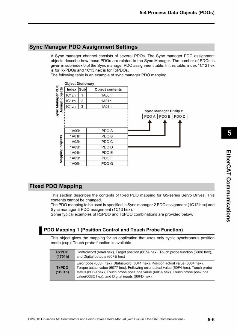
5-4 Process Data Objects (PDOs)
5
EtherCA
T Com
munications
Sync Manager PDO Assignment Settings A Sync manager channel consists of several PDOs. The Sync manager PDO assignmentobjects describe how these PDOs are related to the Sync Manager. The number of PDOs isgiven in sub-index 0 of the Sync manager PDO assignment table. In this table, index 1C12 hexis for RxPDOs and 1C13 hex is for TxPDOs.The following table is an example of sync manager PDO mapping.
Fixed PDO MappingThis section describes the contents of fixed PDO mapping for G5-series Servo Drives. Thiscontents cannot be changed.The PDO mapping to be used is specified in Sync manager 2 PDO assignment (1C12 hex) andSync manager 3 PDO assignment (1C13 hex).Some typical examples of RxPDO and TxPDO combinations are provided below.
PDO Mapping 1 (Position Control and Touch Probe Function)This object gives the mapping for an application that uses only cyclic synchronous positionmode (csp). Touch probe function is available.
RxPDO (1701h)
Controlword (6040 hex), Target position (607A hex), Touch probe function (60B8 hex), and Digital outputs (60FE hex)
TxPDO (1B01h)
Error code (603F hex), Statusword (6041 hex), Position actual value (6064 hex), Torque actual value (6077 hex), Following error actual value (60F4 hex), Touch probe status (60B9 hex), Touch probe pos1 pos value (60BA hex), Touch probe pos2 pos value(60BC hex), and Digital inputs (60FD hex)
Object DictionaryIndex Sub Object contents
1C1zh1C1zh1C1zh
1A00h1A01h1A03h
PDO APDO BPDO C
PDO FPDO EPDO D
PDO G
PDO A PDO B PDO D
1A00h1A01h1A02h1A03h1A04h1A05h1A06h
123
Sync Manager Entity z
Sync
Man
ager
PD
OA
ssig
n ob
ject
sM
appi
ng o
bjec
ts
5-6OMNUC G5-series AC Servomotors and Servo Drives User’s Manual (with Built-in EtherCAT Communications)
5-4 Process Data Objects (PDOs)
5
Ethe
rCA
T C
omm
unic
atio
ns
PDO Mapping 2 (Position Control, Speed Control, Torque Control, andTouch Probe Function)
This is the mapping for an application that uses one of the following modes: Cyclicsynchronous position mode (csp), Cyclic synchronous velocity mode, and Cyclic synchronoustorque mode. Touch probe function is available.
PDO Mapping 3 (Position Control, Speed Control, Touch Probe Function,and Torque Limit)
This is the mapping for an application that switches between Cyclic synchronous positionmode (csp) and Cyclic synchronous velocity mode. Touch probe function and torque limit canbe used.
PDO Mapping 4 (Position Control, Speed Control, Torque Control, TouchProbe Function, and Torque Limit)
This is the mapping for an application that uses one of the following modes: Cyclicsynchronous position mode (csp), Cyclic synchronous velocity mode, and Cyclic synchronoustorque mode. Touch probe function and torque limit can be used.
RxPDO (1702h)
Controlword (6040 hex), Target position (607A hex), Target velocity (60FF hex), Target torque (6071 hex), Modes of operation (6060 hex), Touch probe function (60B8 hex), and Max profile velocity (607F hex)
TxPDO (1B02h)
Error code (603F hex), Statusword (6041 hex), Position actual value (6064 hex), Torque actual value (6077 hex), Modes of operation display (6061 hex), Touch probe status (60B9 hex), Touch probe pos1 pos value (60BA hex), Touch probe pos2 pos value(60BC hex), and Digital inputs (60FD hex)
RxPDO (1703h)
Controlword (6040 hex), Target position (607A hex), Target velocity (60FF hex), Modes of operation (6060 hex), Touch probe function (60B8 hex), Positive torque limit value (60E0 hex), and Negative torque limit value (60E1 hex)
TxPDO (1B03h)
Error code (603F hex), Statusword (6041 hex), Position actual value (6064 hex), Torque actual value (6077 hex), Following error actual value (60F4 hex), Modes of operation display (6061 hex),Touch probe status (60B9 hex), Touch probe pos1 pos value (60BA hex), Touch probe pos2 pos value(60BC hex), and Digital inputs (60FD hex)
RxPDO (1704h)
Controlword (6040 hex), Target position (607A hex), Target velocity (60FF hex), Target torque (6071 hex), Modes of operation (6060 hex), Touch probe function (60B8 hex), Max profile velocity (607F hex), Positive torque limit value (60E0 hex), and Negative torque limit value (60E1 hex)
TxPDO (1B02h)
Error code (603F hex), Statusword (6041 hex), Position actual value (6064 hex), Torque actual value (6077 hex), Modes of operation display (6061 hex), Touch probe status (60B9 hex), Touch probe pos1 pos value (60BA hex), Touch probe pos2 pos value(60BC hex), and Digital inputs (60FD hex)
5-7 OMNUC G5-series AC Servomotors and Servo Drives User’s Manual (with Built-in EtherCAT Communications)
5-4 Process Data Objects (PDOs)
5
EtherCA
T Com
munications
PDO Mapping 5 (Position Control, Speed Control, Touch Probe Function,Torque Limit, and Torque FF)
This is the mapping for an application that switches between Cyclic synchronous positionmode (csp) and Cyclic synchronous velocity mode. Touch probe function and torque limit canbe used. The torque feed-forward amount can be specified by using the Torque offset (60B2hex).
RxPDO (1705h)
Controlword (6040 hex), Target position (607A hex), Target velocity (60FF hex), Modes of operation (6060 hex), Touch probe function (60B8 hex), Positive torque limit value (60E0 hex), Negative torque limit value (60E1 hex), and Torque offset (60B2 hex)
TxPDO (1B04h)
Error code (603F hex), Statusword (6041 hex), Position actual value (6064 hex), Torque actual value (6077 hex), Modes of operation display (6061 hex), Following error actual value (60F4 hex), Touch probe status (60B9 hex), Touch probe pos1 pos value (60BA hex), Digital inputs (60FD hex), and Velocity actual value (606C hex)
5-8OMNUC G5-series AC Servomotors and Servo Drives User’s Manual (with Built-in EtherCAT Communications)
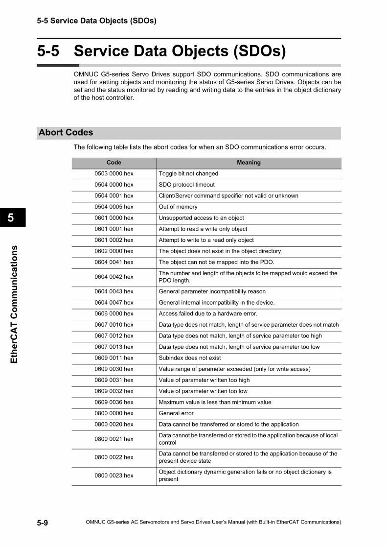
5-5 Service Data Objects (SDOs)
5
Ethe
rCA
T C
omm
unic
atio
ns
5-5 Service Data Objects (SDOs)OMNUC G5-series Servo Drives support SDO communications. SDO communications areused for setting objects and monitoring the status of G5-series Servo Drives. Objects can beset and the status monitored by reading and writing data to the entries in the object dictionaryof the host controller.
Abort CodesThe following table lists the abort codes for when an SDO communications error occurs.
Code Meaning
0503 0000 hex Toggle bit not changed
0504 0000 hex SDO protocol timeout
0504 0001 hex Client/Server command specifier not valid or unknown
0504 0005 hex Out of memory
0601 0000 hex Unsupported access to an object
0601 0001 hex Attempt to read a write only object
0601 0002 hex Attempt to write to a read only object
0602 0000 hex The object does not exist in the object directory
0604 0041 hex The object can not be mapped into the PDO.
0604 0042 hex The number and length of the objects to be mapped would exceed the PDO length.
0604 0043 hex General parameter incompatibility reason
0604 0047 hex General internal incompatibility in the device.
0606 0000 hex Access failed due to a hardware error.
0607 0010 hex Data type does not match, length of service parameter does not match
0607 0012 hex Data type does not match, length of service parameter too high
0607 0013 hex Data type does not match, length of service parameter too low
0609 0011 hex Subindex does not exist
0609 0030 hex Value range of parameter exceeded (only for write access)
0609 0031 hex Value of parameter written too high
0609 0032 hex Value of parameter written too low
0609 0036 hex Maximum value is less than minimum value
0800 0000 hex General error
0800 0020 hex Data cannot be transferred or stored to the application
0800 0021 hex Data cannot be transferred or stored to the application because of local control
0800 0022 hex Data cannot be transferred or stored to the application because of the present device state
0800 0023 hex Object dictionary dynamic generation fails or no object dictionary is present
5-9 OMNUC G5-series AC Servomotors and Servo Drives User’s Manual (with Built-in EtherCAT Communications)
5-6 Synchronization with Distributed Clocks
5
EtherCA
T Com
munications
5-6 Synchronization with Distributed ClocksA mechanism called a distributed clock (DC) is used to synchronize EtherCAT communications.The DC mode is used for OMNUC G5-series Servo Drives to perform highly accurate control in a multi-axis system.In DC mode, the master and slaves are synchronized by sharing the same clock.Interruptions (Sync0) are generated in the slaves at precise intervals based on this clock.Servo Drive control is carried out at this precise timing.
Communications Cycle (DC Cycle)The communications cycle is determined by setting the Sync0 signal output cycle.
Setting range: 250 µs/500 µs/1 ms/2 ms/4 ms
Precautions for Correct Use
Set 6091 hex (Gear ratio) to 1:1 for 250 µs or 500 µs. If it is not set to 1:1, a Function SettingError (Error 93.4) will occur.
5-10OMNUC G5-series AC Servomotors and Servo Drives User’s Manual (with Built-in EtherCAT Communications)
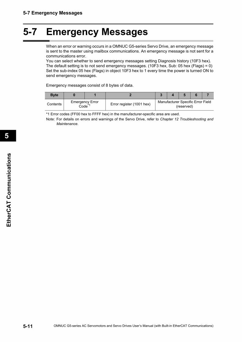
5-7 Emergency Messages
5
Ethe
rCA
T C
omm
unic
atio
ns
5-7 Emergency MessagesWhen an error or warning occurs in a OMNUC G5-series Servo Drive, an emergency messageis sent to the master using mailbox communications. An emergency message is not sent for acommunications error.You can select whether to send emergency messages setting Diagnosis history (10F3 hex).The default setting is to not send emergency messages. (10F3 hex, Sub: 05 hex (Flags) = 0)Set the sub-index 05 hex (Flags) in object 10F3 hex to 1 every time the power is turned ON tosend emergency messages.
Emergency messages consist of 8 bytes of data.
*1 Error codes (FF00 hex to FFFF hex) in the manufacturer-specific area are used.Note: For details on errors and warnings of the Servo Drive, refer to Chapter 12 Troubleshooting and
Maintenance.
Byte 0 1 2 3 4 5 6 7
Contents Emergency Error Code*1 Error register (1001 hex) Manufacturer Specific Error Field
(reserved)
5-11 OMNUC G5-series AC Servomotors and Servo Drives User’s Manual (with Built-in EtherCAT Communications)
6
Basic Control FunctionsThis chapter explains an outline of basic control functions and explains thecontents of setting.
6-1 Cyclic Synchronous Position Mode............................6-16-2 Cyclic Synchronous Velocity Mode............................6-46-3 Cyclic Synchronous Torque Mode..............................6-76-4 Homing Mode..............................................................6-116-5 Fully-closed Control ...................................................6-126-6 Connecting with OMRON Controllers.......................6-19
OMNUC G5-series AC Servomotors and Servo Drives User’s Manual (with Built-in EtherCAT Communications)
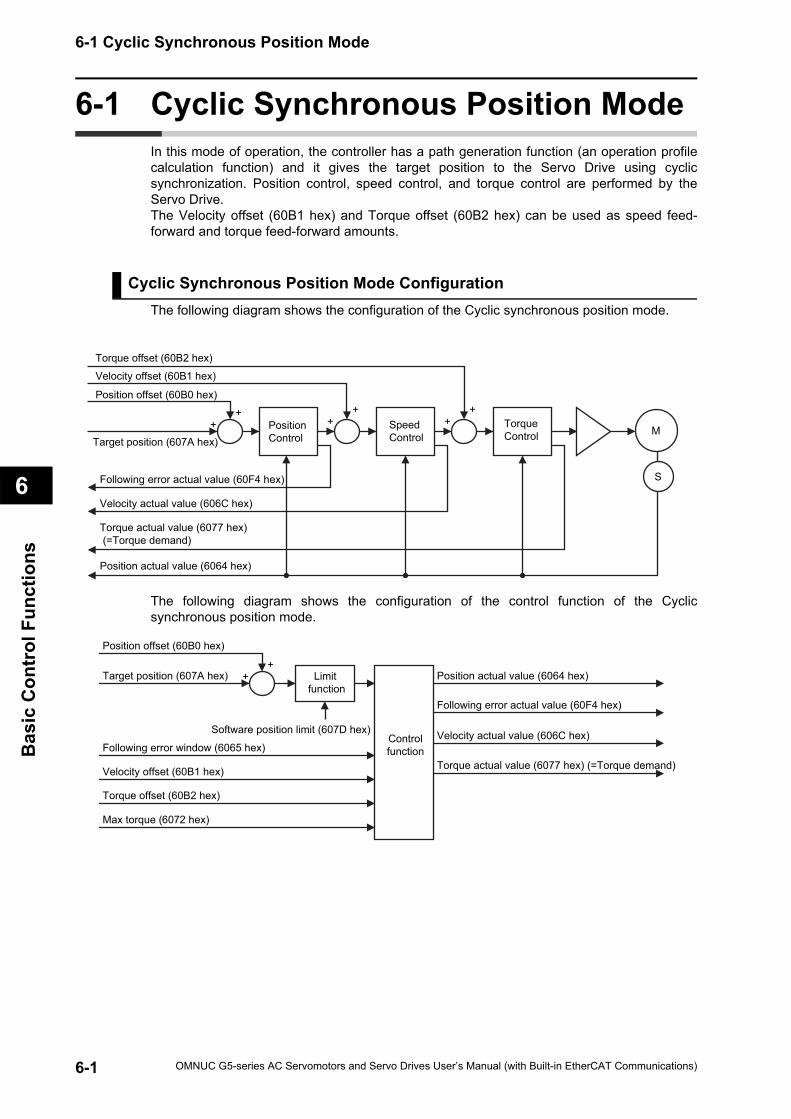
6-1 Cyclic Synchronous Position Mode
6
Bas
ic C
ontr
ol F
unct
ions
6-1 Cyclic Synchronous Position ModeIn this mode of operation, the controller has a path generation function (an operation profilecalculation function) and it gives the target position to the Servo Drive using cyclicsynchronization. Position control, speed control, and torque control are performed by theServo Drive.The Velocity offset (60B1 hex) and Torque offset (60B2 hex) can be used as speed feed-forward and torque feed-forward amounts.
Cyclic Synchronous Position Mode ConfigurationThe following diagram shows the configuration of the Cyclic synchronous position mode.
The following diagram shows the configuration of the control function of the Cyclicsynchronous position mode.
Target position (607A hex)Position Control
Speed Control
Torque Control
S
M
Following error actual value (60F4 hex)
Position actual value (6064 hex)
Torque actual value (6077 hex) (=Torque demand)
++
Position offset (60B0 hex)
++
++
Velocity offset (60B1 hex)
Torque offset (60B2 hex)
Velocity actual value (606C hex)
Target position (607A hex)
Following error window (6065 hex)
Position actual value (6064 hex)
Following error actual value (60F4 hex)
Torque actual value (6077 hex) (=Torque demand)
Velocity actual value (606C hex)Controlfunction
Limit function
Software position limit (607D hex)
++
Position offset (60B0 hex)
Velocity offset (60B1 hex)
Torque offset (60B2 hex)
Max torque (6072 hex)
6-1 OMNUC G5-series AC Servomotors and Servo Drives User’s Manual (with Built-in EtherCAT Communications)
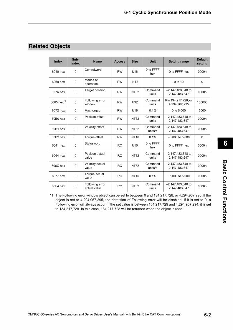
6-1 Cyclic Synchronous Position Mode
6
Basic C
ontrol Functions
Related Objects
*1 The Following error window object can be set to between 0 and 134,217,728, or 4,294,967,295. If theobject is set to 4,294,967,295, the detection of Following error will be disabled. If it is set to 0, aFollowing error will always occur. If the set value is between 134,217,729 and 4,294,967,294, it is setto 134,217,728. In this case, 134,217,728 will be returned when the object is read.
Index Sub-index Name Access Size Unit Setting range Default
setting
6040 hex 0 Controlword RW U16 0 to FFFF hex 0 to FFFF hex 0000h
6060 hex 0 Modes of operation RW INT8 − 0 to 10 0
607A hex 0 Target position RW INT32 Command units
−2,147,483,648 to 2,147,483,647 0000h
6065 hex*1 0 Following error window RW U32 Command
units0 to 134,217,728, or
4,294,967,295 100000
6072 hex 0 Max torque RW U16 0.1% 0 to 5,000 5000
60B0 hex 0 Position offset RW INT32 Command units
−2,147,483,648 to 2,147,483,647 0000h
60B1 hex 0 Velocity offset RW INT32 Command units/s
−2,147,483,648 to 2,147,483,647 0000h
60B2 hex 0 Torque offset RW INT16 0.1% −5,000 to 5,000 0
6041 hex 0 Statusword RO U16 0 to FFFF hex 0 to FFFF hex 0000h
6064 hex 0 Position actual value RO INT32 Command
units−2,147,483,648 to
2,147,483,647 0000h
606C hex 0 Velocity actual value RO INT32 Command
units/s−2,147,483,648 to
2,147,483,647 0000h
6077 hex 0 Torque actual value RO INT16 0.1% −5,000 to 5,000 0000h
60F4 hex 0 Following error actual value RO INT32 Command
units−2,147,483,648 to
2,147,483,647 0000h
6-2OMNUC G5-series AC Servomotors and Servo Drives User’s Manual (with Built-in EtherCAT Communications)
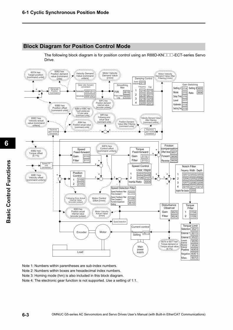
6-1 Cyclic Synchronous Position Mode
6
Bas
ic C
ontr
ol F
unct
ions
Block Diagram for Position Control ModeThe following block diagram is for position control using an R88D-KN@@@-ECT-series ServoDrive.
Note 1: Numbers within parentheses are sub-index numbers.Note 2: Numbers within boxes are hexadecimal index numbers.Note 3: Homing mode (hm) is also included in this block diagram.Note 4: The electronic gear function is not supported. Use a setting of 1:1.
3611
Speed Feed-forwardGain 3110Filter 3111
6091(01)
6091(02)FIR 3818
3222
+
−
Position Control1 31002 3105
++
1 32142 32163 3218
321532173219
4 3220 3221
3213
+
−
360736083609
36233624
Setting 2 3114Mode 3115Delay Time 3116Level 3117Hysteresis 3118Switching Time 3119
Setting 3 3605
Ratio 3606
31043109
31123113
+−
+
+
+++
Notch Filter
3203320632093212
Depth3202320532083211
Width1 32012 32043 32074 3210
Frequency
Adaptive Filter Selection 3200
31023107
Linear Integral
Inertia Ratio
1 31012 3106
3004
++
++
607A hexTarget position
[command units]
6062 hexPosition demand value [command
units]
Velocity Demand Value [command
units/s]
Motor Velocity Demand Value
[r/min]
Motor Velocity Demand Value After
Filtering [r/min]
Gear ratio forward conversion
Numerator
Denominator
Smoothing filter
First-order Lag
Damping ControlSwitch
SelectionFrequency Filter
Gain Switching
60FC hexPosition demand
internal value [encoder pulses]60BA or 60BC hex
Touch probe pos 1/2 pos value
[command units]606C hex
Velocity actual value [command
units/s]6064 hex
Position actual value [command units]
60F4 hexFollowing error
actual value[command units] Position Demand
Value After Filtering [command units]
Velocity Demand Value After Filtering
[command units/s]
Electronic gear reverse conversion
Electronic gear reverse conversion
60B2 hexTorque offset
[0.1%]
60B1 hexVelocity offset
[command units/s]
60FA hexControl effort
[command units/s]Torque
Feed-forwardGainFilter
Friction compensationOffset ValueForward
Reverse Speed FF
unit conversion Speed Control
Following Error Actual Internal Value
[encoder pulses]
Motor Control Effort [r/min]
6063 hexPosition actual internal value
[encoder pulses]
Motor Velocity Actual Value
[r/min]
Disturbance Observer
GainFilter
12
Torque Filter
Speed detection
Encoder Motor
Load
Current control
Response Setting
Main power supply
6074 or 6077 hexTorque demand or
Torque actual value [0.1%]
3521
60E060E1
External 1 3013External 2 3522Forward External 3525Reverse External 3526
Max. 6072
SelectionTorque Limit
PositiveNegative
3103
31083610
Speed Detection FilterSpeed Feedback Filter Time Constant 1Speed Feedback Filter Time Constant 2Function Expansion Setting
Generate Position
Command
+
+
60B0 hexPosition offset
[command units]
6-3 OMNUC G5-series AC Servomotors and Servo Drives User’s Manual (with Built-in EtherCAT Communications)
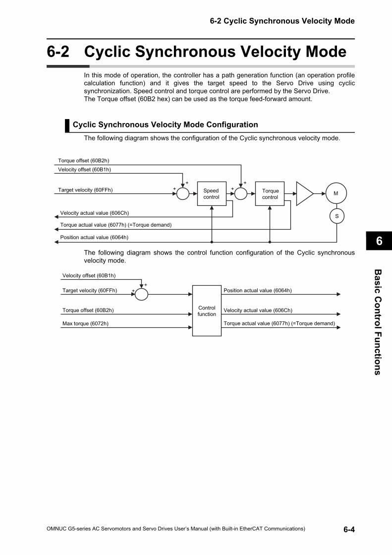
6-2 Cyclic Synchronous Velocity Mode
6
Basic C
ontrol Functions
6-2 Cyclic Synchronous Velocity ModeIn this mode of operation, the controller has a path generation function (an operation profilecalculation function) and it gives the target speed to the Servo Drive using cyclicsynchronization. Speed control and torque control are performed by the Servo Drive.The Torque offset (60B2 hex) can be used as the torque feed-forward amount.
Cyclic Synchronous Velocity Mode ConfigurationThe following diagram shows the configuration of the Cyclic synchronous velocity mode.
The following diagram shows the control function configuration of the Cyclic synchronousvelocity mode.
Target velocity (60FFh)
S
M
Position actual value (6064h)
Torque actual value (6077h) (=Torque demand)
++
++
Velocity offset (60B1h)
Torque offset (60B2h)
Velocity actual value (606Ch)
Speed control
Torque control
Target velocity (60FFh) Position actual value (6064h)
Torque actual value (6077h) (=Torque demand)
Velocity actual value (606Ch)
++
Velocity offset (60B1h)
Torque offset (60B2h)
Max torque (6072h)
Controlfunction
6-4OMNUC G5-series AC Servomotors and Servo Drives User’s Manual (with Built-in EtherCAT Communications)
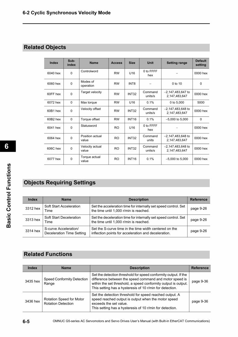
6-2 Cyclic Synchronous Velocity Mode
6
Bas
ic C
ontr
ol F
unct
ions
Related Objects
Objects Requiring Settings
Related Functions
Index Sub-index Name Access Size Unit Setting range Default
setting
6040 hex 0 Controlword RW U16 0 to FFFF hex − 0000 hex
6060 hex 0 Modes of operation RW INT8 − 0 to 10 0
60FF hex 0 Target velocity RW INT32 Command units/s
−2,147,483,647 to 2,147,483,647 0000 hex
6072 hex 0 Max torque RW U16 0.1% 0 to 5,000 5000
60B1 hex 0 Velocity offset RW INT32 Command units/s
−2,147,483,648 to 2,147,483,647 0000 hex
60B2 hex 0 Torque offset RW INT16 0.1% −5,000 to 5,000 0
6041 hex 0 Statusword RO U16 0 to FFFF hex − 0000 hex
6064 hex 0 Position actual value RO INT32 Command
units−2,147,483,648 to
2,147,483,647 0000 hex
606C hex 0 Velocity actual value RO INT32 Command
units/s−2,147,483,648 to
2,147,483,647 0000 hex
6077 hex 0 Torque actual value RO INT16 0.1% −5,000 to 5,000 0000 hex
Index Name Description Reference
3312 hex Soft Start Acceleration Time
Set the acceleration time for internally set speed control. Set the time until 1,000 r/min is reached. page 9-26
3313 hex Soft Start Deceleration Time
Set the deceleration time for internally set speed control. Set the time until 1,000 r/min is reached. page 9-26
3314 hex S-curve Acceleration/Deceleration Time Setting
Set the S-curve time in the time width centered on the inflection points for acceleration and deceleration. page 9-26
Index Name Description Reference
3435 hex Speed Conformity Detection Range
Set the detection threshold for speed conformity output. If the difference between the speed command and motor speed is within the set threshold, a speed conformity output is output.This setting has a hysteresis of 10 r/min for detection.
page 9-36
3436 hex Rotation Speed for Motor Rotation Detection
Set the detection threshold for speed reached output. A speed reached output is output when the motor speed exceeds the set value.This setting has a hysteresis of 10 r/min for detection.
page 9-36
6-5 OMNUC G5-series AC Servomotors and Servo Drives User’s Manual (with Built-in EtherCAT Communications)
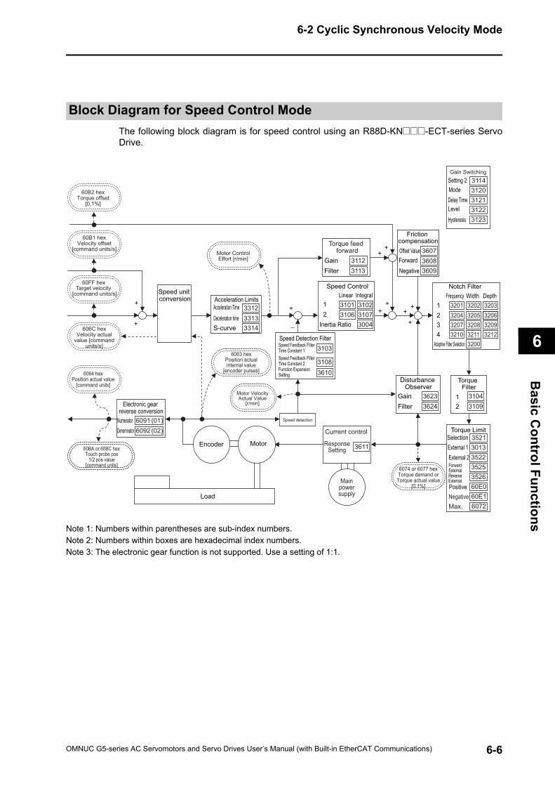
6-2 Cyclic Synchronous Velocity Mode
6
Basic C
ontrol Functions
Block Diagram for Speed Control ModeThe following block diagram is for speed control using an R88D-KN@@@-ECT-series ServoDrive.
Note 1: Numbers within parentheses are sub-index numbers.Note 2: Numbers within boxes are hexadecimal index numbers.Note 3: The electronic gear function is not supported. Use a setting of 1:1.
3611Encoder Motor
36073608
Negative 3609
Acceleration LimitsAcceleration Time 3312Deceleration time 3313S-curve 3314
Disturbance Observer
Gain 3623Filter 3624Electronic gear
reverse conversionNumerator 6091 (01)Denominator 6092 (02)
Speed unit conversion
31043109
3521
60E060E1
3013352235253526
Torque feed forward
Gain 3112Filter 3113
Speed Control
31023107
Inertia Ratio
31013106
3004
Load6072
31143120312131223123
60FF hex Target velocity
[command units/s]
Speed Detection Filter3103
31083610
+
++
−
Setting 2ModeDelay TimeLevel
Hysteresis
+
++
+
Notch Filter
3203320632093212
Depth3202320532083211
Width1 32012 32043 32074 3210
Frequency
Adaptive Filter Selection 3200
Linear Integral
++
+
Gain Switching
60BA or 60BC hexTouch probe pos
1/2 pos value [command units]
606C hexVelocity actual
value [command units/s]
6064 hexPosition actual value
[command units]
60B2 hexTorque offset
[0.1%]
60B1 hexVelocity offset
[command units/s]
Friction compensationOffset ValueForward
Motor Control Effort [r/min]
6063 hexPosition actual internal value
[encoder pulses]
Motor Velocity Actual Value
[r/min]12
Torque Filter
Speed detection
Current control
Response Setting
Main power supply
6074 or 6077 hexTorque demand or
Torque actual value [0.1%]
External 1External 2ForwardExternalReverse External
Max.
SelectionTorque Limit
PositiveNegative
Speed Feedback Filter Time Constant 1Speed Feedback Filter Time Constant 2Function Expansion Setting
12
6-6OMNUC G5-series AC Servomotors and Servo Drives User’s Manual (with Built-in EtherCAT Communications)
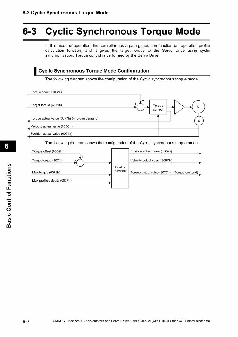
6-3 Cyclic Synchronous Torque Mode
6
Bas
ic C
ontr
ol F
unct
ions
6-3 Cyclic Synchronous Torque ModeIn this mode of operation, the controller has a path generation function (an operation profilecalculation function) and it gives the target torque to the Servo Drive using cyclicsynchronization. Torque control is performed by the Servo Drive.
Cyclic Synchronous Torque Mode ConfigurationThe following diagram shows the configuration of the Cyclic synchronous torque mode.
The following diagram shows the configuration of the Cyclic synchronous torque mode.
Target torque (6071h)
Velocity actual value (606Ch)
S
M
Position actual value (6064h)
Torque actual value (6077h) (=Torque demand)
++
Torque offset (60B2h)
Torque control
Target torque (6071h) Velocity actual value (606Ch)
Position actual value (6064h)
Torque actual value (6077h) (=Torque demand)
++
Torque offset (60B2h)
Max torque (6072h)
Max profile velocity (607Fh)
Controlfunction
6-7 OMNUC G5-series AC Servomotors and Servo Drives User’s Manual (with Built-in EtherCAT Communications)
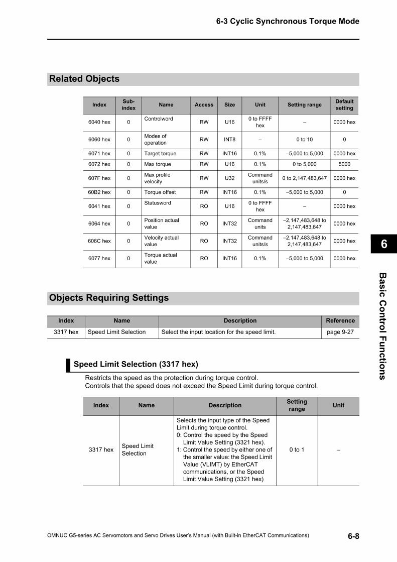
6-3 Cyclic Synchronous Torque Mode
6
Basic C
ontrol Functions
Related Objects
Objects Requiring Settings
Speed Limit Selection (3317 hex)Restricts the speed as the protection during torque control.Controls that the speed does not exceed the Speed Limit during torque control.
Index Sub-index Name Access Size Unit Setting range Default
setting
6040 hex 0 Controlword RW U16 0 to FFFF hex − 0000 hex
6060 hex 0 Modes of operation RW INT8 − 0 to 10 0
6071 hex 0 Target torque RW INT16 0.1% −5,000 to 5,000 0000 hex
6072 hex 0 Max torque RW U16 0.1% 0 to 5,000 5000
607F hex 0 Max profile velocity RW U32 Command
units/s 0 to 2,147,483,647 0000 hex
60B2 hex 0 Torque offset RW INT16 0.1% −5,000 to 5,000 0
6041 hex 0 Statusword RO U16 0 to FFFF hex − 0000 hex
6064 hex 0 Position actual value RO INT32 Command
units−2,147,483,648 to
2,147,483,647 0000 hex
606C hex 0 Velocity actual value RO INT32 Command
units/s−2,147,483,648 to
2,147,483,647 0000 hex
6077 hex 0 Torque actual value RO INT16 0.1% −5,000 to 5,000 0000 hex
Index Name Description Reference
3317 hex Speed Limit Selection Select the input location for the speed limit. page 9-27
Index Name Description Settingrange Unit
3317 hex Speed Limit Selection
Selects the input type of the Speed Limit during torque control.0: Control the speed by the Speed
Limit Value Setting (3321 hex).1: Control the speed by either one of
the smaller value: the Speed Limit Value (VLIMT) by EtherCAT communications, or the Speed Limit Value Setting (3321 hex)
0 to 1 −
6-8OMNUC G5-series AC Servomotors and Servo Drives User’s Manual (with Built-in EtherCAT Communications)
6-3 Cyclic Synchronous Torque Mode
6
Bas
ic C
ontr
ol F
unct
ions
Related Functions
Index Name Description Reference
3321 hex Speed Limit Value Setting
Set the speed limit value applicable during torque control. During torque control, the speed is controlled so as not to exceed the level set by the speed limit value.
page 9-27
6-9 OMNUC G5-series AC Servomotors and Servo Drives User’s Manual (with Built-in EtherCAT Communications)
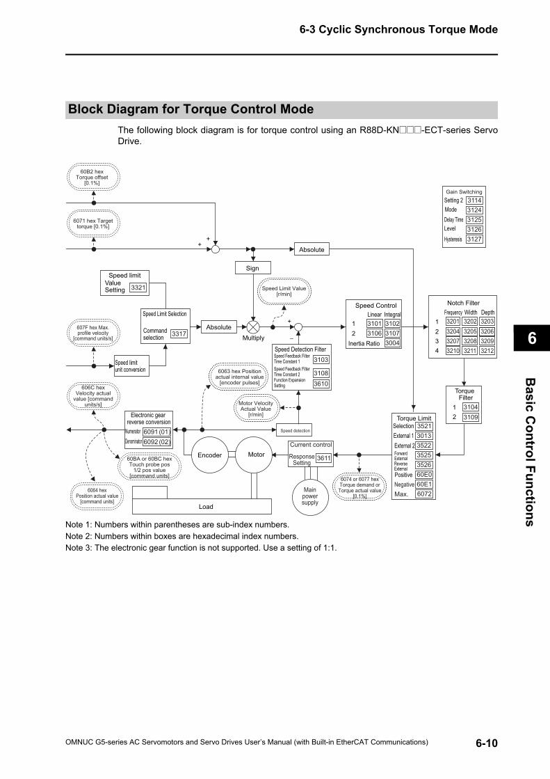
6-3 Cyclic Synchronous Torque Mode
6
Basic C
ontrol Functions
Block Diagram for Torque Control ModeThe following block diagram is for torque control using an R88D-KN@@@-ECT-series ServoDrive.
Note 1: Numbers within parentheses are sub-index numbers.Note 2: Numbers within boxes are hexadecimal index numbers.Note 3: The electronic gear function is not supported. Use a setting of 1:1.
3611
Speed Limit Selection
Command selection 3317
Speed limitValue Setting 3321
Sign
Absolute
Absolute
Speed limit unit conversion
31043109
3103
31083610
3203320632093212
3202320532083211
3201320432073210
31023107
31013106
3004Multiply
6091 (01)6092 (02)
Encoder Motor
Electronic gear reverse conversion
NumeratorDenominator
3521
60E060E1
3013352235253526
Speed Control
Inertia Ratio
Load
6072
31143124312531263127
Speed Detection Filter
−
Setting 2ModeDelay TimeLevel
Hysteresis
+
Notch FilterDepthWidth
1234
FrequencyLinear Integral
++
Gain Switching
606C hex Velocity actual
value [command units/s]
6064 hex Position actual value
[command units]
60B2 hex Torque offset
[0.1%]
60BA or 60BC hex Touch probe pos
1/2 pos value [command units]
607F hex Max. profile velocity
[command units/s]
12
Torque Filter
Speed detection
Current control
Response Setting
Main power supply
6074 or 6077 hexTorque demand or
Torque actual value [0.1%]
External 1External 2ForwardExternalReverseExternal
Max.
SelectionTorque Limit
PositiveNegative
Speed Feedback Filter Time Constant 1Speed Feedback Filter Time Constant 2Function Expansion Setting
12
6071 hex Target torque [0.1%]
6063 hex Position actual internal value
[encoder pulses]
Speed Limit Value [r/min]
Motor Velocity Actual Value
[r/min]
6-10OMNUC G5-series AC Servomotors and Servo Drives User’s Manual (with Built-in EtherCAT Communications)
6-4 Homing Mode
6
Bas
ic C
ontr
ol F
unct
ions
6-4 Homing ModeIn this mode of operation, the Servo Drive has a path generation function (an operation profilecalculation function) and it executes the homing operation using the Homing method specifiedfrom the controller.When a controller is connected, the following two homing procedures are available dependingon the controller specifications.
Procedure 1Create a homing operation pattern in the controller, and provide the command to the Servo Driveusing Cyclic synchronous position mode (csp).Procedure 2Use the Homing mode of the Servo Drive. The controller specifies a homing method supported bythe Servo Drive and commands the start of the homing operation.
When performing the homing operation using the controller in procedure 1, refer to theoperating manual for the controller.When performing the homing operation using the controller in procedure 2, refer to theoperating manual for the controller, and to Homing Mode Specifications on page A-11 of thismanual.
Reference
Procedure 1 is used for the OMRON CJ1W-NC281/NC481/NC881/NCF81/NC482/NC882 Position Control Units. Create a homing operation pattern in the Position Control Unit, provide the command to the Servo Drive using the Cyclic synchronous position mode (csp), and perform the homing operation.
6-11 OMNUC G5-series AC Servomotors and Servo Drives User’s Manual (with Built-in EtherCAT Communications)
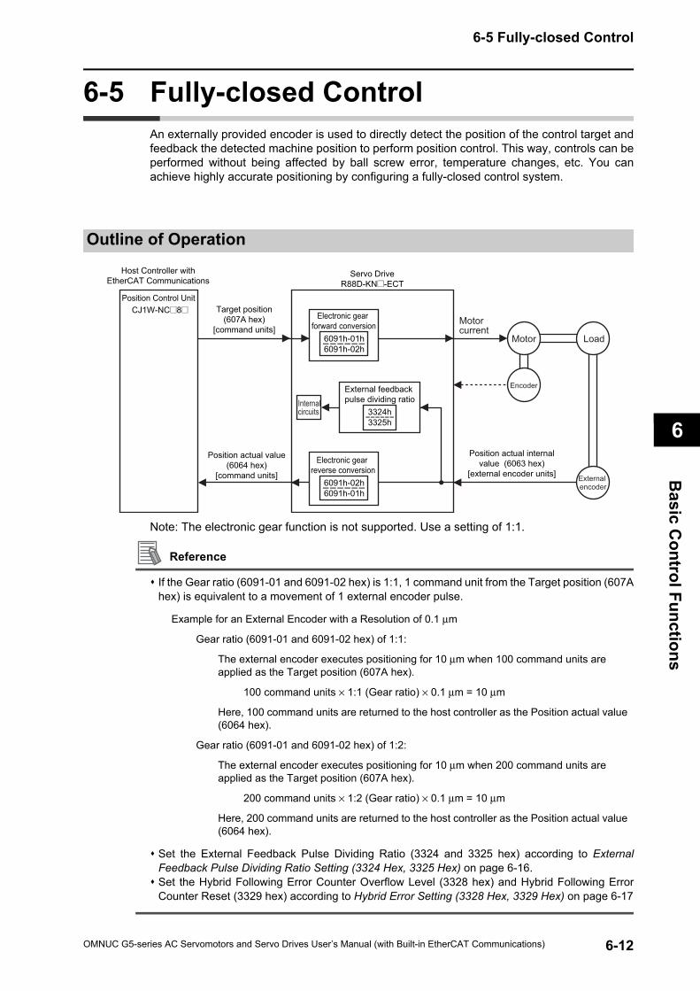
6-5 Fully-closed Control
6
Basic C
ontrol Functions
6-5 Fully-closed ControlAn externally provided encoder is used to directly detect the position of the control target andfeedback the detected machine position to perform position control. This way, controls can beperformed without being affected by ball screw error, temperature changes, etc. You canachieve highly accurate positioning by configuring a fully-closed control system.
Outline of Operation
Note: The electronic gear function is not supported. Use a setting of 1:1.
Reference
If the Gear ratio (6091-01 and 6091-02 hex) is 1:1, 1 command unit from the Target position (607Ahex) is equivalent to a movement of 1 external encoder pulse.
Set the External Feedback Pulse Dividing Ratio (3324 and 3325 hex) according to ExternalFeedback Pulse Dividing Ratio Setting (3324 Hex, 3325 Hex) on page 6-16. Set the Hybrid Following Error Counter Overflow Level (3328 hex) and Hybrid Following ErrorCounter Reset (3329 hex) according to Hybrid Error Setting (3328 Hex, 3329 Hex) on page 6-17
------
------
------
Position Control UnitCJ1W-NC@8@
Servo DriveR88D-KN@-ECT
Electronic gear forward conversion
6091h-01h6091h-02h
Electronic gear reverse conversion
6091h-02h6091h-01h
External feedback pulse dividing ratio
3324h3325h
Motor
Motor current
Encoder
Load
External encoder
Host Controller with EtherCAT Communications
Target position (607A hex)
[command units]
Position actual value (6064 hex)
[command units]
Internal circuits
Position actual internal value (6063 hex)
[external encoder units]
Example for an External Encoder with a Resolution of 0.1 µm
Gear ratio (6091-01 and 6091-02 hex) of 1:1:
The external encoder executes positioning for 10 µm when 100 command units are applied as the Target position (607A hex).
100 command units × 1:1 (Gear ratio) × 0.1 µm = 10 µm
Here, 100 command units are returned to the host controller as the Position actual value (6064 hex).
Gear ratio (6091-01 and 6091-02 hex) of 1:2:
The external encoder executes positioning for 10 µm when 200 command units are applied as the Target position (607A hex).
200 command units × 1:2 (Gear ratio) × 0.1 µm = 10 µm
Here, 200 command units are returned to the host controller as the Position actual value (6064 hex).
6-12OMNUC G5-series AC Servomotors and Servo Drives User’s Manual (with Built-in EtherCAT Communications)
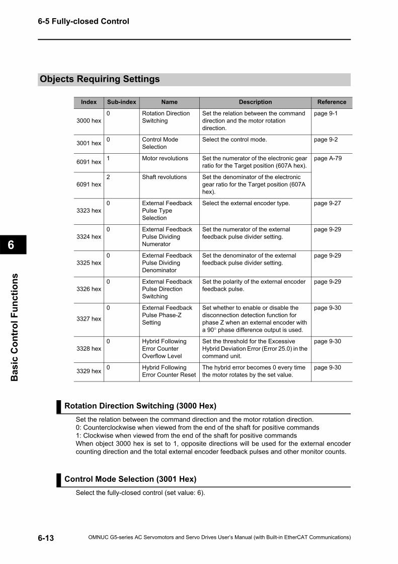
6-5 Fully-closed Control
6
Bas
ic C
ontr
ol F
unct
ions
Objects Requiring Settings
Rotation Direction Switching (3000 Hex)Set the relation between the command direction and the motor rotation direction.0: Counterclockwise when viewed from the end of the shaft for positive commands1: Clockwise when viewed from the end of the shaft for positive commandsWhen object 3000 hex is set to 1, opposite directions will be used for the external encodercounting direction and the total external encoder feedback pulses and other monitor counts.
Control Mode Selection (3001 Hex)Select the fully-closed control (set value: 6).
Index Sub-index Name Description Reference
3000 hex0 Rotation Direction
SwitchingSet the relation between the command direction and the motor rotation direction.
page 9-1
3001 hex 0 Control Mode Selection
Select the control mode. page 9-2
6091 hex 1 Motor revolutions Set the numerator of the electronic gear ratio for the Target position (607A hex).
page A-79
6091 hex2 Shaft revolutions Set the denominator of the electronic
gear ratio for the Target position (607A hex).
3323 hex0 External Feedback
Pulse Type Selection
Select the external encoder type. page 9-27
3324 hex0 External Feedback
Pulse Dividing Numerator
Set the numerator of the external feedback pulse divider setting.
page 9-29
3325 hex0 External Feedback
Pulse Dividing Denominator
Set the denominator of the external feedback pulse divider setting.
page 9-29
3326 hex0 External Feedback
Pulse Direction Switching
Set the polarity of the external encoder feedback pulse.
page 9-29
3327 hex
0 External Feedback Pulse Phase-Z Setting
Set whether to enable or disable the disconnection detection function for phase Z when an external encoder with a 90° phase difference output is used.
page 9-30
3328 hex0 Hybrid Following
Error Counter Overflow Level
Set the threshold for the Excessive Hybrid Deviation Error (Error 25.0) in the command unit.
page 9-30
3329 hex 0 Hybrid Following Error Counter Reset
The hybrid error becomes 0 every time the motor rotates by the set value.
page 9-30
6-13 OMNUC G5-series AC Servomotors and Servo Drives User’s Manual (with Built-in EtherCAT Communications)
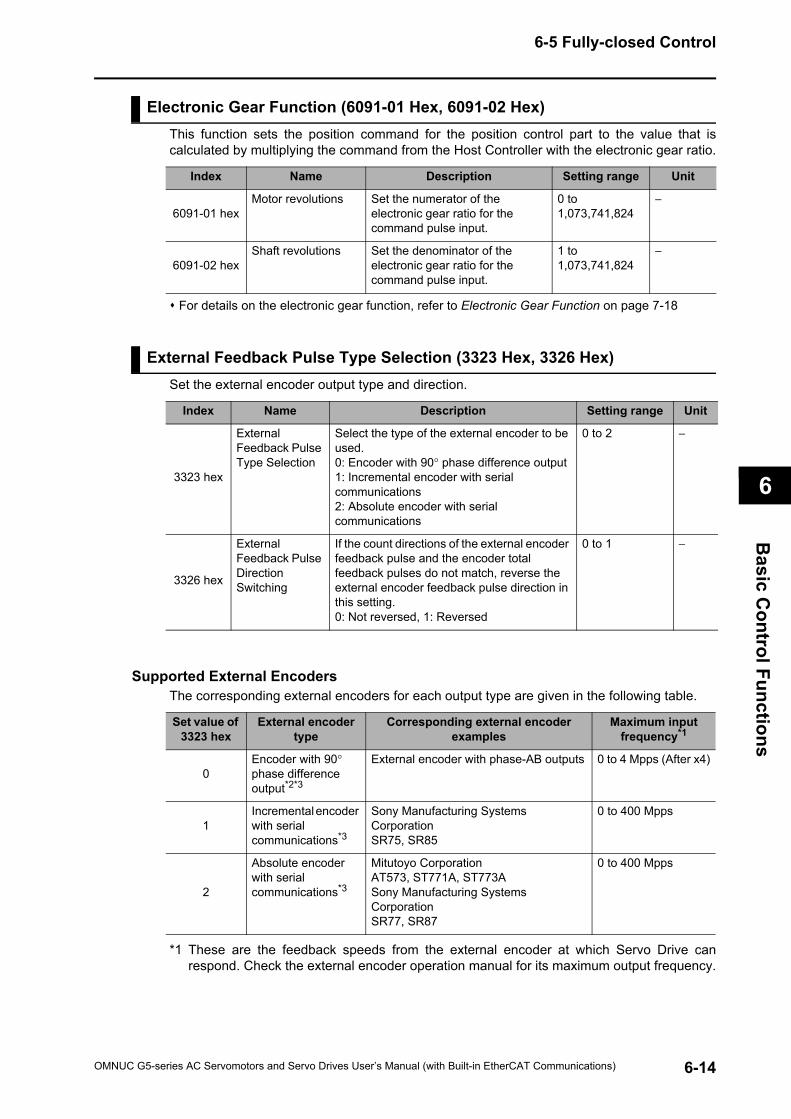
6-5 Fully-closed Control
6
Basic C
ontrol Functions
Electronic Gear Function (6091-01 Hex, 6091-02 Hex)This function sets the position command for the position control part to the value that iscalculated by multiplying the command from the Host Controller with the electronic gear ratio.
For details on the electronic gear function, refer to Electronic Gear Function on page 7-18
External Feedback Pulse Type Selection (3323 Hex, 3326 Hex)Set the external encoder output type and direction.
Supported External EncodersThe corresponding external encoders for each output type are given in the following table.
*1 These are the feedback speeds from the external encoder at which Servo Drive canrespond. Check the external encoder operation manual for its maximum output frequency.
Index Name Description Setting range Unit
6091-01 hexMotor revolutions Set the numerator of the
electronic gear ratio for the command pulse input.
0 to 1,073,741,824
−
6091-02 hexShaft revolutions Set the denominator of the
electronic gear ratio for the command pulse input.
1 to 1,073,741,824
−
Index Name Description Setting range Unit
3323 hex
External Feedback Pulse Type Selection
Select the type of the external encoder to be used.0: Encoder with 90° phase difference output1: Incremental encoder with serial communications2: Absolute encoder with serial communications
0 to 2 −
3326 hex
External Feedback Pulse Direction Switching
If the count directions of the external encoder feedback pulse and the encoder total feedback pulses do not match, reverse the external encoder feedback pulse direction in this setting.0: Not reversed, 1: Reversed
0 to 1 −
Set value of 3323 hex
External encoder type
Corresponding external encoder examples
Maximum input frequency*1
0Encoder with 90° phase difference output*2*3
External encoder with phase-AB outputs 0 to 4 Mpps (After x4)
1Incremental encoder with serial communications*3
Sony Manufacturing Systems CorporationSR75, SR85
0 to 400 Mpps
2
Absolute encoder with serial communications*3
Mitutoyo CorporationAT573, ST771A, ST773ASony Manufacturing Systems CorporationSR77, SR87
0 to 400 Mpps
6-14OMNUC G5-series AC Servomotors and Servo Drives User’s Manual (with Built-in EtherCAT Communications)
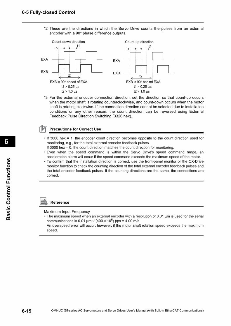
6-5 Fully-closed Control
6
Bas
ic C
ontr
ol F
unct
ions
*2 These are the directions in which the Servo Drive counts the pulses from an externalencoder with a 90° phase difference outputs.
*3 For the external encoder connection direction, set the direction so that count-up occurswhen the motor shaft is rotating counterclockwise, and count-down occurs when the motorshaft is rotating clockwise. If the connection direction cannot be selected due to installationconditions or any other reason, the count direction can be reversed using ExternalFeedback Pulse Direction Switching (3326 hex).
Precautions for Correct Use
If 3000 hex = 1, the encoder count direction becomes opposite to the count direction used formonitoring, e.g., for the total external encoder feedback pulses.If 3000 hex = 0, the count direction matches the count direction for monitoring.Even when the speed command is within the Servo Drive's speed command range, anacceleration alarm will occur if the speed command exceeds the maximum speed of the motor.To confirm that the installation direction is correct, use the front-panel monitor or the CX-Drivemonitor function to check the counting direction of the total external encoder feedback pulses andthe total encoder feedback pulses. If the counting directions are the same, the connections arecorrect.
Reference
Maximum Input FrequencyThe maximum speed when an external encoder with a resolution of 0.01 µm is used for the serialcommunications is 0.01 µm × (400 × 106) pps = 4.00 m/s.An overspeed error will occur, however, if the motor shaft rotation speed exceeds the maximumspeed.
Count-down direction
EXB is 90° ahead of EXA. t1 > 0.25 µs t2 > 1.0 µs
EXB is 90° behind EXA. t1 > 0.25 µst2 > 1.0 µs
t1
t2
t1
t2
EXA
EXB
EXA
EXB
Count-up direction
6-15 OMNUC G5-series AC Servomotors and Servo Drives User’s Manual (with Built-in EtherCAT Communications)
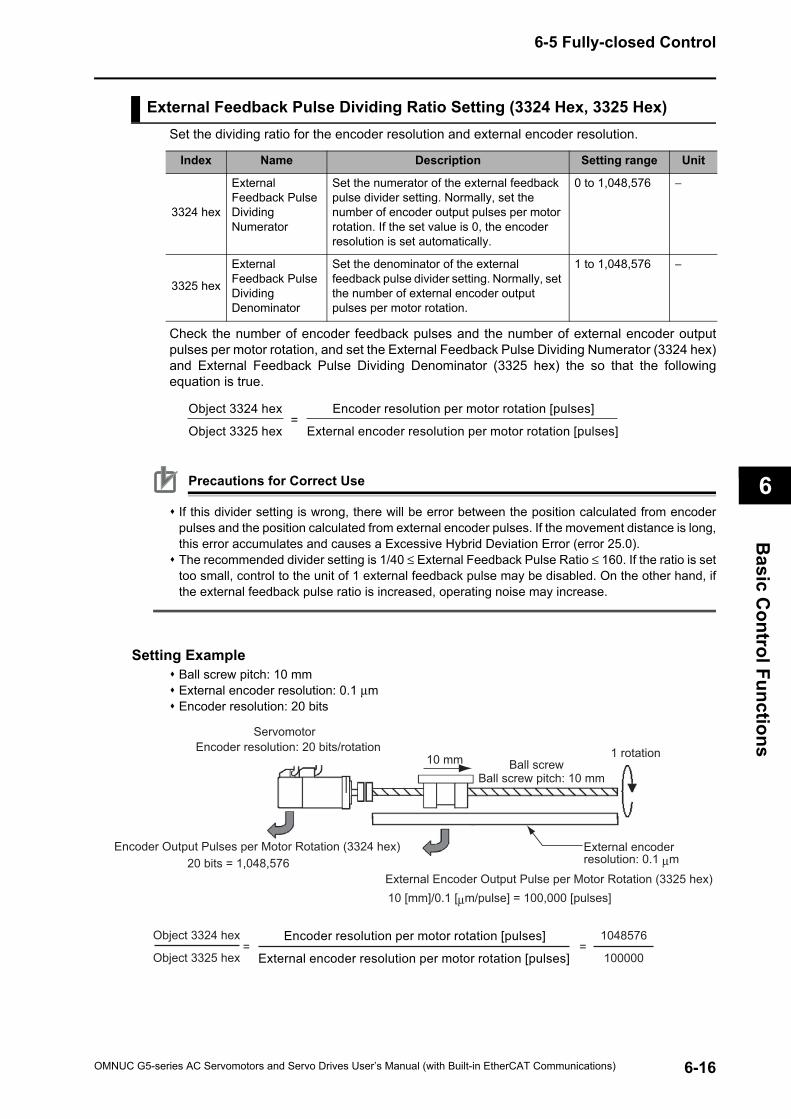
6-5 Fully-closed Control
6
Basic C
ontrol Functions
External Feedback Pulse Dividing Ratio Setting (3324 Hex, 3325 Hex)Set the dividing ratio for the encoder resolution and external encoder resolution.
Check the number of encoder feedback pulses and the number of external encoder outputpulses per motor rotation, and set the External Feedback Pulse Dividing Numerator (3324 hex)and External Feedback Pulse Dividing Denominator (3325 hex) the so that the followingequation is true.
Precautions for Correct Use
If this divider setting is wrong, there will be error between the position calculated from encoderpulses and the position calculated from external encoder pulses. If the movement distance is long,this error accumulates and causes a Excessive Hybrid Deviation Error (error 25.0).The recommended divider setting is 1/40 ≤ External Feedback Pulse Ratio ≤ 160. If the ratio is settoo small, control to the unit of 1 external feedback pulse may be disabled. On the other hand, ifthe external feedback pulse ratio is increased, operating noise may increase.
Setting ExampleBall screw pitch: 10 mmExternal encoder resolution: 0.1 µmEncoder resolution: 20 bits
Index Name Description Setting range Unit
3324 hex
External Feedback Pulse Dividing Numerator
Set the numerator of the external feedback pulse divider setting. Normally, set the number of encoder output pulses per motor rotation. If the set value is 0, the encoder resolution is set automatically.
0 to 1,048,576 −
3325 hex
External Feedback Pulse Dividing Denominator
Set the denominator of the external feedback pulse divider setting. Normally, set the number of external encoder output pulses per motor rotation.
1 to 1,048,576 −
=Encoder resolution per motor rotation [pulses]
External encoder resolution per motor rotation [pulses]
Object 3324 hex
Object 3325 hex
ServomotorEncoder resolution: 20 bits/rotation
10 mm Ball screwBall screw pitch: 10 mm
1 rotation
External encoder resolution: 0.1 µm
External Encoder Output Pulse per Motor Rotation (3325 hex)10 [mm]/0.1 [µm/pulse] = 100,000 [pulses]
Encoder Output Pulses per Motor Rotation (3324 hex)20 bits = 1,048,576
Object 3325 hex
Object 3324 hex=
100000
1048576Encoder resolution per motor rotation [pulses]
External encoder resolution per motor rotation [pulses]=
6-16OMNUC G5-series AC Servomotors and Servo Drives User’s Manual (with Built-in EtherCAT Communications)
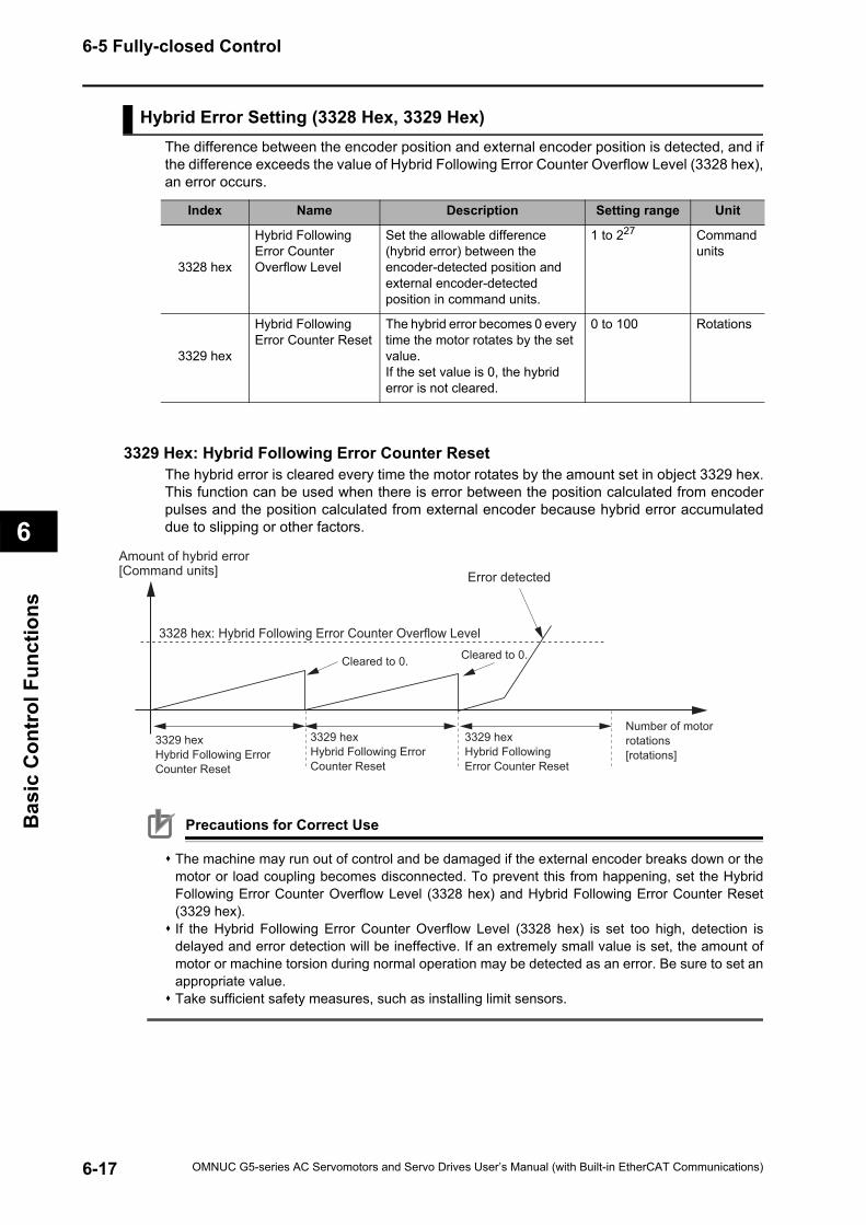
6-5 Fully-closed Control
6
Bas
ic C
ontr
ol F
unct
ions
Hybrid Error Setting (3328 Hex, 3329 Hex)The difference between the encoder position and external encoder position is detected, and ifthe difference exceeds the value of Hybrid Following Error Counter Overflow Level (3328 hex),an error occurs.
3329 Hex: Hybrid Following Error Counter ResetThe hybrid error is cleared every time the motor rotates by the amount set in object 3329 hex.This function can be used when there is error between the position calculated from encoderpulses and the position calculated from external encoder because hybrid error accumulateddue to slipping or other factors.
Precautions for Correct Use
The machine may run out of control and be damaged if the external encoder breaks down or themotor or load coupling becomes disconnected. To prevent this from happening, set the HybridFollowing Error Counter Overflow Level (3328 hex) and Hybrid Following Error Counter Reset(3329 hex).If the Hybrid Following Error Counter Overflow Level (3328 hex) is set too high, detection isdelayed and error detection will be ineffective. If an extremely small value is set, the amount ofmotor or machine torsion during normal operation may be detected as an error. Be sure to set anappropriate value.Take sufficient safety measures, such as installing limit sensors.
Index Name Description Setting range Unit
3328 hex
Hybrid Following Error Counter Overflow Level
Set the allowable difference (hybrid error) between the encoder-detected position and external encoder-detected position in command units.
1 to 227 Command units
3329 hex
Hybrid Following Error Counter Reset
The hybrid error becomes 0 every time the motor rotates by the set value.If the set value is 0, the hybrid error is not cleared.
0 to 100 Rotations
Amount of hybrid error[Command units] Error detected
3328 hex: Hybrid Following Error Counter Overflow Level
3329 hexHybrid Following Error Counter Reset
3329 hexHybrid Following Error Counter Reset
3329 hexHybrid Following Error Counter Reset
Cleared to 0. Cleared to 0.
Number of motor rotations [rotations]
6-17 OMNUC G5-series AC Servomotors and Servo Drives User’s Manual (with Built-in EtherCAT Communications)
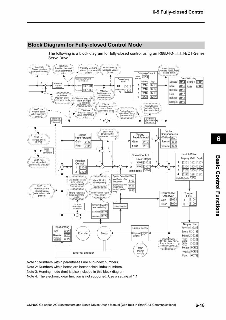
6-5 Fully-closed Control
6
Basic C
ontrol Functions
Block Diagram for Fully-closed Control ModeThe following is a block diagram for fully-closed control using an R88D-KN@@@-ECT-SeriesServo Drive.
Note 1: Numbers within parentheses are sub-index numbers.Note 2: Numbers within boxes are hexadecimal index numbers.Note 3: Homing mode (hm) is also included in this block diagram.Note 4: The electronic gear function is not supported. Use a setting of 1:1.
+
-31003105
++ +
-
36233624
31043109
3611
+
+
+++
3203320632093212
3202320532083211
3201320432073210
3200
31023107
31013106
3004
332333263327
33253324+-
6091(01)6091(02)
38183222
3218
3118
32173219
3220 3221
+-
360736083609
31123113
31103111 +
+
3213
32143216
3215
3119
36053606
3114311531163117
External encoder
++
Speed Feed-forwardGainFilter
FIR
Position Control12
1234
Setting 2ModeDelay TimeLevelHysteresisSwitching Time
Setting 3
Ratio
Notch FilterDepthWidth
1234
Frequency
Adaptive Filter Selection
Linear Integral
Inertia Ratio
12
6062 hexPosition demand value [command
units]
Velocity Demand Value [command
units/s]
Motor Velocity Demand Value
[r/min]Motor Velocity
Demand Value After Filtering [r/min]
Gear ratio forward conversion
Numerator
Denominator
Smoothing filter
First-order Lag
Damping ControlSwitch
SelectionFrequency Filter
Gain Switching
60BA or 60BC hexTouch probe pos
1/2 pos value [command units]
606C hexVelocity actual
value [command units/s]
6064 hexPosition actual
value [command units]
60F4 hexFollowing error
actual value[command units] Position Demand
Value After Filtering [command units]
Velocity Demand Value After Filtering [command units/s]
Electronic gear reverse conversion
Electronic gear reverse conversion
60B2 hexTorque offset
[0.1%]
60B1 hexVelocity offset
[command units/s]
60FA hexControl effort
[command units/s]Torque
Feed-forwardGainFilter
Friction CompensationOffset ValueForward
Reverse Speed FF
unit conversion
Speed Control
Fully-closed Following Error [external
encoder pulses]
Motor Control Effort [r/min]
6063 hexPosition actual internal value
[external encoder pulses]
Motor Velocity Actual Value [r/min]
Disturbance Observer
GainFilter
12
Torque Filter
Speed detection
Encoder Motor
Current control
Response Setting
Main power supply
6074 or 6077 hex Torque demand or
Torque actual value [0.1%]
Electronic gear reverse conversion
Hybrid Following Error [command
units]
Input settingTypeReversePhase Z disabled
External Encoder reverse dividing
Denominator
Numerator
60FC hexPosition demand
internal value [encoder pulses]
3103
31083610
Speed Detection Filter
3521
60E060E1
3013352235253526
6072
External 1External 2ForwardExternalReverseExternal
Max.
SelectionTorque Limit
PositiveNegative
Speed Feedback Filter Time Constant 1Speed Feedback Filter Time Constant 2Function Expansion Setting
607A hexTarget position
[command units]
+
+
Generate Position
Command
60B0 hexPosition offset
[command units]
6-18OMNUC G5-series AC Servomotors and Servo Drives User’s Manual (with Built-in EtherCAT Communications)
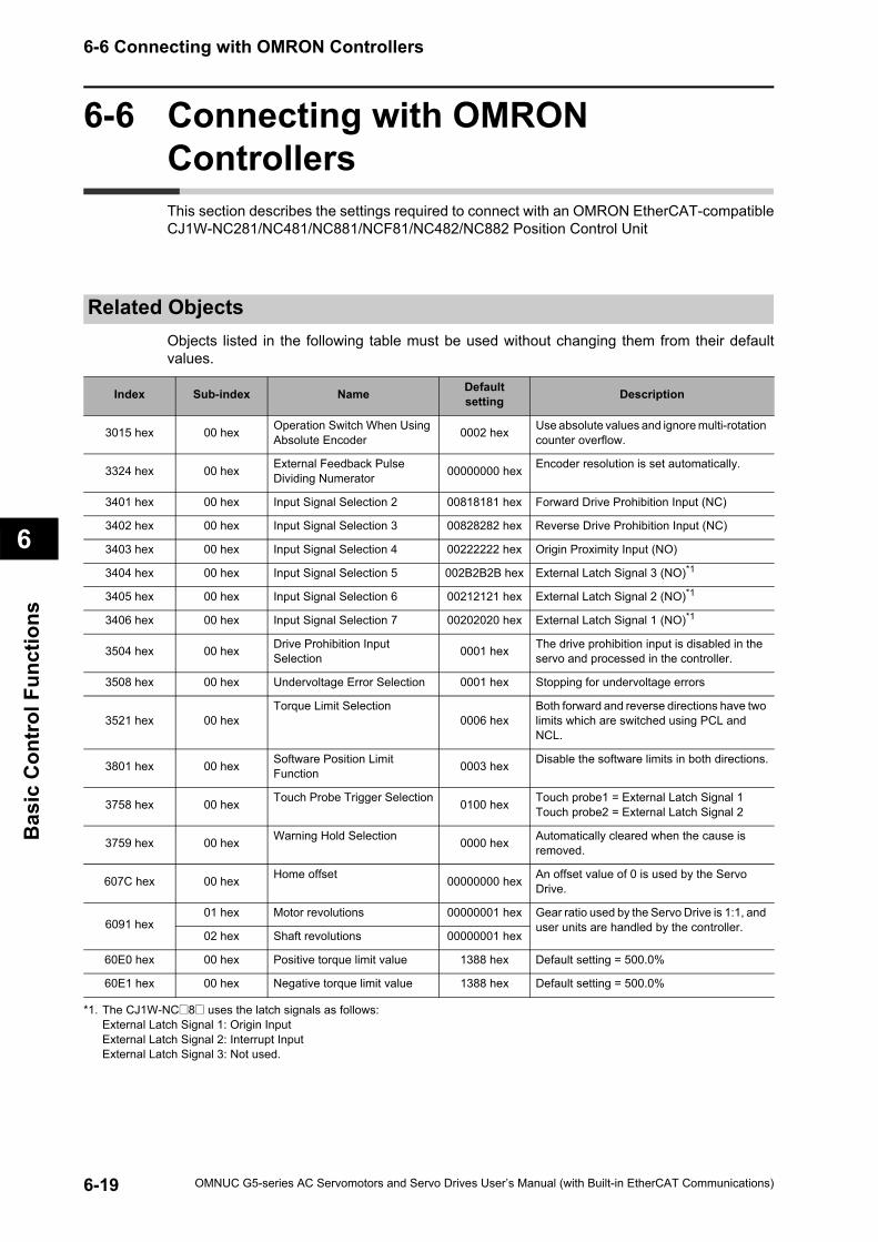
6-6 Connecting with OMRON Controllers
6
Bas
ic C
ontr
ol F
unct
ions
6-6 Connecting with OMRON ControllersThis section describes the settings required to connect with an OMRON EtherCAT-compatibleCJ1W-NC281/NC481/NC881/NCF81/NC482/NC882 Position Control Unit
Related ObjectsObjects listed in the following table must be used without changing them from their defaultvalues.
*1. The CJ1W-NC@8@ uses the latch signals as follows:External Latch Signal 1: Origin InputExternal Latch Signal 2: Interrupt InputExternal Latch Signal 3: Not used.
Index Sub-index Name Default setting Description
3015 hex 00 hex Operation Switch When Using Absolute Encoder 0002 hex Use absolute values and ignore multi-rotation
counter overflow.
3324 hex 00 hex External Feedback Pulse Dividing Numerator 00000000 hex Encoder resolution is set automatically.
3401 hex 00 hex Input Signal Selection 2 00818181 hex Forward Drive Prohibition Input (NC)
3402 hex 00 hex Input Signal Selection 3 00828282 hex Reverse Drive Prohibition Input (NC)
3403 hex 00 hex Input Signal Selection 4 00222222 hex Origin Proximity Input (NO)
3404 hex 00 hex Input Signal Selection 5 002B2B2B hex External Latch Signal 3 (NO)*1
3405 hex 00 hex Input Signal Selection 6 00212121 hex External Latch Signal 2 (NO)*1
3406 hex 00 hex Input Signal Selection 7 00202020 hex External Latch Signal 1 (NO)*1
3504 hex 00 hex Drive Prohibition Input Selection 0001 hex The drive prohibition input is disabled in the
servo and processed in the controller.
3508 hex 00 hex Undervoltage Error Selection 0001 hex Stopping for undervoltage errors
3521 hex 00 hexTorque Limit Selection
0006 hexBoth forward and reverse directions have two limits which are switched using PCL and NCL.
3801 hex 00 hex Software Position Limit Function 0003 hex Disable the software limits in both directions.
3758 hex 00 hex Touch Probe Trigger Selection 0100 hex Touch probe1 = External Latch Signal 1Touch probe2 = External Latch Signal 2
3759 hex 00 hex Warning Hold Selection 0000 hex Automatically cleared when the cause is removed.
607C hex 00 hex Home offset 00000000 hex An offset value of 0 is used by the Servo Drive.
6091 hex01 hex Motor revolutions 00000001 hex Gear ratio used by the Servo Drive is 1:1, and
user units are handled by the controller.02 hex Shaft revolutions 00000001 hex
60E0 hex 00 hex Positive torque limit value 1388 hex Default setting = 500.0%
60E1 hex 00 hex Negative torque limit value 1388 hex Default setting = 500.0%
6-19 OMNUC G5-series AC Servomotors and Servo Drives User’s Manual (with Built-in EtherCAT Communications)
7
Applied FunctionsThis chapter outlines the applied functions such as the electronic gear, gainswitching and soft start, and explains the settings.
7-1 Sequence I/O Signals ...................................................7-17-2 Forward and Reverse Drive Prohibition Functions ...7-67-3 Overrun Protection .......................................................7-97-4 Backlash Compensation............................................7-117-5 Brake Interlock............................................................7-137-6 Electronic Gear Function ...........................................7-187-7 Torque Limit Switching ..............................................7-217-8 Soft Start......................................................................7-237-9 Gain Switching Function............................................7-257-10 Gain Switching 3 Function.........................................7-357-11 Touch Probe Function (Latch Function) ..................7-37
OMNUC G5-series AC Servomotors and Servo Drives User’s Manual (with Built-in EtherCAT Communications)
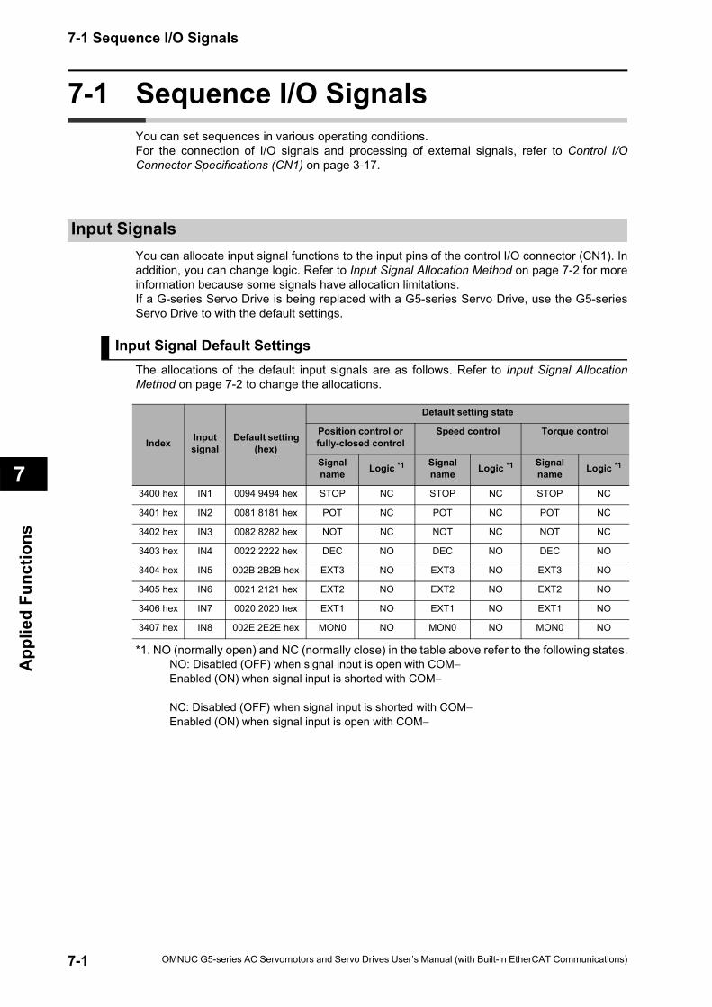
7-1 Sequence I/O Signals
7
App
lied
Func
tions
7-1 Sequence I/O SignalsYou can set sequences in various operating conditions.For the connection of I/O signals and processing of external signals, refer to Control I/OConnector Specifications (CN1) on page 3-17.
Input SignalsYou can allocate input signal functions to the input pins of the control I/O connector (CN1). Inaddition, you can change logic. Refer to Input Signal Allocation Method on page 7-2 for moreinformation because some signals have allocation limitations.If a G-series Servo Drive is being replaced with a G5-series Servo Drive, use the G5-seriesServo Drive to with the default settings.
Input Signal Default SettingsThe allocations of the default input signals are as follows. Refer to Input Signal AllocationMethod on page 7-2 to change the allocations.
*1. NO (normally open) and NC (normally close) in the table above refer to the following states.NO: Disabled (OFF) when signal input is open with COM−Enabled (ON) when signal input is shorted with COM−
NC: Disabled (OFF) when signal input is shorted with COM−Enabled (ON) when signal input is open with COM−
Index Input signal
Default setting (hex)
Default setting state
Position control or fully-closed control
Speed control Torque control
Signal name Logic *1 Signal
name Logic *1 Signal name Logic *1
3400 hex IN1 0094 9494 hex STOP NC STOP NC STOP NC
3401 hex IN2 0081 8181 hex POT NC POT NC POT NC
3402 hex IN3 0082 8282 hex NOT NC NOT NC NOT NC
3403 hex IN4 0022 2222 hex DEC NO DEC NO DEC NO
3404 hex IN5 002B 2B2B hex EXT3 NO EXT3 NO EXT3 NO
3405 hex IN6 0021 2121 hex EXT2 NO EXT2 NO EXT2 NO
3406 hex IN7 0020 2020 hex EXT1 NO EXT1 NO EXT1 NO
3407 hex IN8 002E 2E2E hex MON0 NO MON0 NO MON0 NO
7-1 OMNUC G5-series AC Servomotors and Servo Drives User’s Manual (with Built-in EtherCAT Communications)
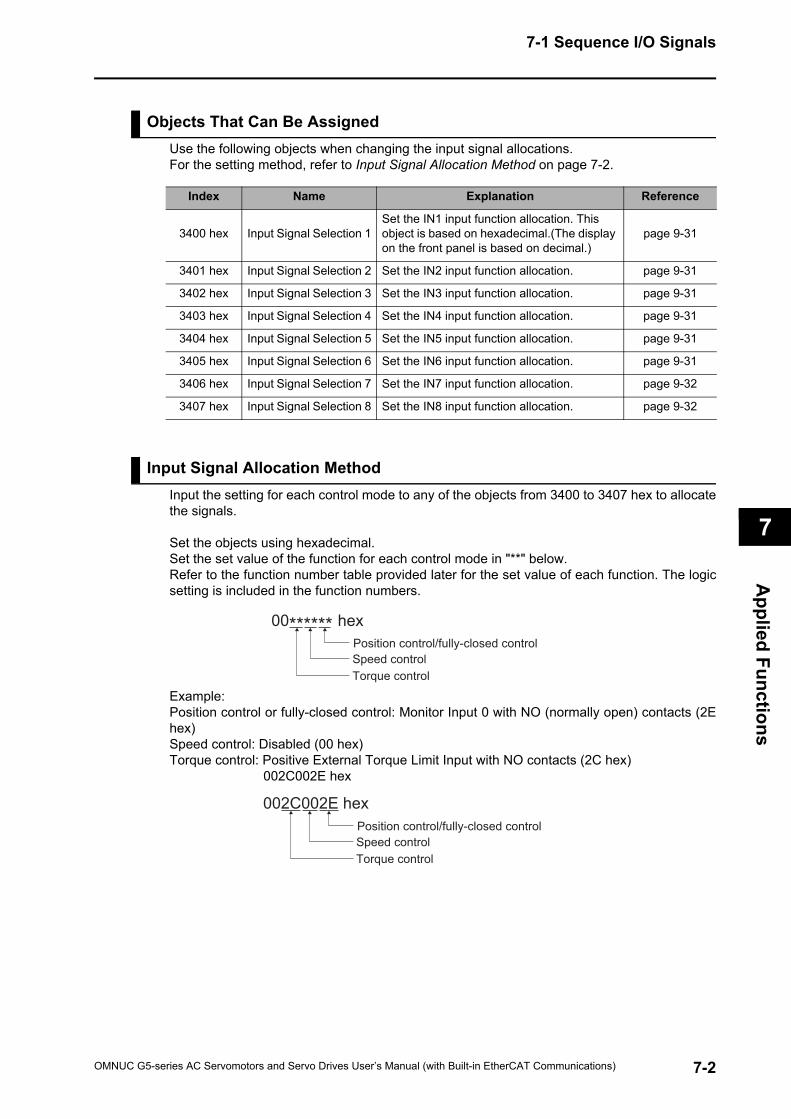
7
7-1 Sequence I/O SignalsA
pplied Functions
Objects That Can Be AssignedUse the following objects when changing the input signal allocations.For the setting method, refer to Input Signal Allocation Method on page 7-2.
Input Signal Allocation MethodInput the setting for each control mode to any of the objects from 3400 to 3407 hex to allocatethe signals.
Set the objects using hexadecimal.Set the set value of the function for each control mode in "**" below.Refer to the function number table provided later for the set value of each function. The logicsetting is included in the function numbers.
Example:Position control or fully-closed control: Monitor Input 0 with NO (normally open) contacts (2Ehex) Speed control: Disabled (00 hex)Torque control: Positive External Torque Limit Input with NO contacts (2C hex)
002C002E hex
Index Name Explanation Reference
3400 hex Input Signal Selection 1Set the IN1 input function allocation. This object is based on hexadecimal.(The display on the front panel is based on decimal.)
page 9-31
3401 hex Input Signal Selection 2 Set the IN2 input function allocation. page 9-31
3402 hex Input Signal Selection 3 Set the IN3 input function allocation. page 9-31
3403 hex Input Signal Selection 4 Set the IN4 input function allocation. page 9-31
3404 hex Input Signal Selection 5 Set the IN5 input function allocation. page 9-31
3405 hex Input Signal Selection 6 Set the IN6 input function allocation. page 9-31
3406 hex Input Signal Selection 7 Set the IN7 input function allocation. page 9-32
3407 hex Input Signal Selection 8 Set the IN8 input function allocation. page 9-32
Position control/fully-closed control
00****** hex
Speed controlTorque control
Position control/fully-closed control
002C002E hex
Speed controlTorque control
7-2OMNUC G5-series AC Servomotors and Servo Drives User’s Manual (with Built-in EtherCAT Communications)
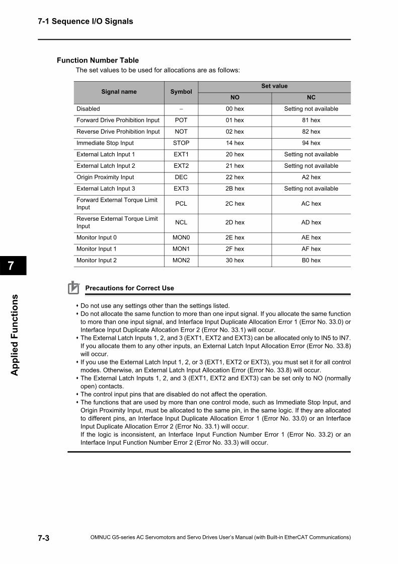
7-1 Sequence I/O Signals
7
App
lied
Func
tions
Function Number TableThe set values to be used for allocations are as follows:
Precautions for Correct Use
Do not use any settings other than the settings listed.Do not allocate the same function to more than one input signal. If you allocate the same functionto more than one input signal, and Interface Input Duplicate Allocation Error 1 (Error No. 33.0) orInterface Input Duplicate Allocation Error 2 (Error No. 33.1) will occur.The External Latch Inputs 1, 2, and 3 (EXT1, EXT2 and EXT3) can be allocated only to IN5 to IN7.If you allocate them to any other inputs, an External Latch Input Allocation Error (Error No. 33.8)will occur. If you use the External Latch Input 1, 2, or 3 (EXT1, EXT2 or EXT3), you must set it for all controlmodes. Otherwise, an External Latch Input Allocation Error (Error No. 33.8) will occur. The External Latch Inputs 1, 2, and 3 (EXT1, EXT2 and EXT3) can be set only to NO (normallyopen) contacts. The control input pins that are disabled do not affect the operation.The functions that are used by more than one control mode, such as Immediate Stop Input, andOrigin Proximity Input, must be allocated to the same pin, in the same logic. If they are allocatedto different pins, an Interface Input Duplicate Allocation Error 1 (Error No. 33.0) or an InterfaceInput Duplicate Allocation Error 2 (Error No. 33.1) will occur. If the logic is inconsistent, an Interface Input Function Number Error 1 (Error No. 33.2) or anInterface Input Function Number Error 2 (Error No. 33.3) will occur.
Signal name SymbolSet value
NO NC
Disabled − 00 hex Setting not available
Forward Drive Prohibition Input POT 01 hex 81 hex
Reverse Drive Prohibition Input NOT 02 hex 82 hex
Immediate Stop Input STOP 14 hex 94 hex
External Latch Input 1 EXT1 20 hex Setting not available
External Latch Input 2 EXT2 21 hex Setting not available
Origin Proximity Input DEC 22 hex A2 hex
External Latch Input 3 EXT3 2B hex Setting not available
Forward External Torque Limit Input PCL 2C hex AC hex
Reverse External Torque Limit Input NCL 2D hex AD hex
Monitor Input 0 MON0 2E hex AE hex
Monitor Input 1 MON1 2F hex AF hex
Monitor Input 2 MON2 30 hex B0 hex
7-3 OMNUC G5-series AC Servomotors and Servo Drives User’s Manual (with Built-in EtherCAT Communications)
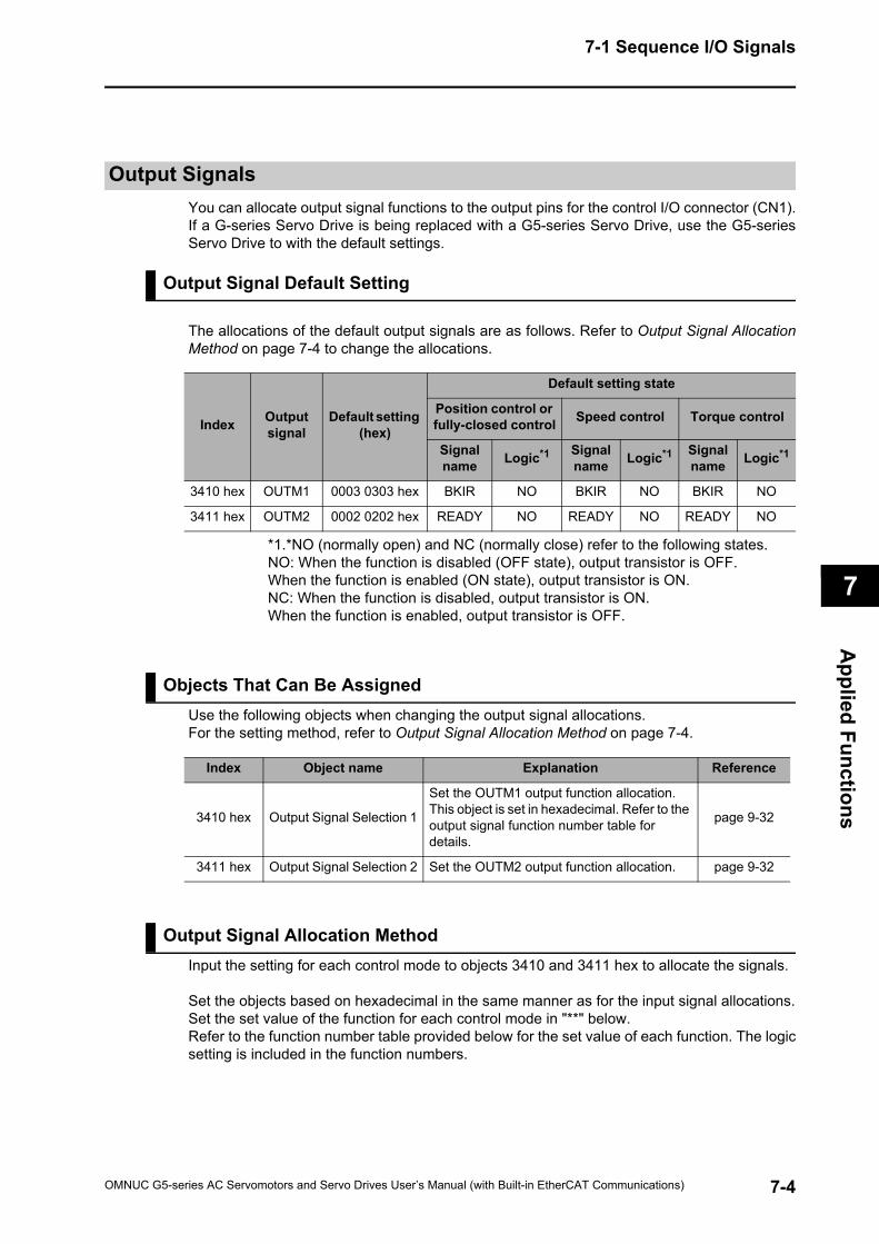
7
7-1 Sequence I/O SignalsA
pplied Functions
Output SignalsYou can allocate output signal functions to the output pins for the control I/O connector (CN1).If a G-series Servo Drive is being replaced with a G5-series Servo Drive, use the G5-seriesServo Drive to with the default settings.
Output Signal Default Setting
The allocations of the default output signals are as follows. Refer to Output Signal AllocationMethod on page 7-4 to change the allocations.
Objects That Can Be Assigned Use the following objects when changing the output signal allocations.For the setting method, refer to Output Signal Allocation Method on page 7-4.
Output Signal Allocation MethodInput the setting for each control mode to objects 3410 and 3411 hex to allocate the signals.
Set the objects based on hexadecimal in the same manner as for the input signal allocations.Set the set value of the function for each control mode in "**" below.Refer to the function number table provided below for the set value of each function. The logicsetting is included in the function numbers.
Index Output signal
Default setting (hex)
Default setting state
Position control or fully-closed control Speed control Torque control
Signal name Logic*1 Signal
name Logic*1 Signal name Logic*1
3410 hex OUTM1 0003 0303 hex BKIR NO BKIR NO BKIR NO
3411 hex OUTM2 0002 0202 hex READY NO READY NO READY NO
*1.*NO (normally open) and NC (normally close) refer to the following states.NO: When the function is disabled (OFF state), output transistor is OFF.When the function is enabled (ON state), output transistor is ON.NC: When the function is disabled, output transistor is ON.When the function is enabled, output transistor is OFF.
Index Object name Explanation Reference
3410 hex Output Signal Selection 1
Set the OUTM1 output function allocation. This object is set in hexadecimal. Refer to the output signal function number table for details.
page 9-32
3411 hex Output Signal Selection 2 Set the OUTM2 output function allocation. page 9-32
7-4OMNUC G5-series AC Servomotors and Servo Drives User’s Manual (with Built-in EtherCAT Communications)
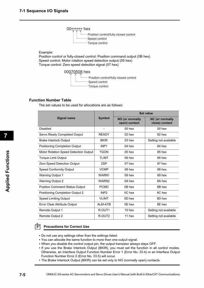
7-1 Sequence I/O Signals
7
App
lied
Func
tions
Example:Position control or fully-closed control: Position command output (0B hex)Speed control: Motor rotation speed detection output (05 hex)Torque control: Zero speed detection signal (07 hex)
Function Number TableThe set values to be used for allocations are as follows:
Precautions for Correct Use
Do not use any settings other than the settings listed.You can allocate the same function to more than one output signal.When you disable the control output pin, the output transistor always stays OFF.If you use the Brake Interlock Output (BKIR), you must set the function in all control modes.Otherwise, an Interface Output Function Number Error 1 (Error No. 33.4) or an Interface OutputFunction Number Error 2 (Error No. 33.5) will occur. The Brake Interlock Output (BKIR) can be set only to NO (normally open) contacts.
Signal name SymbolSet value
NO (or normally open) contact
NC (or normally close) contact
Disabled − 00 hex 00 hex
Servo Ready Completed Output READY 02 hex 82 hex
Brake Interlock Output BKIR 03 hex Setting not available
Positioning Completion Output INP1 04 hex 84 hex
Motor Rotation Speed Detection Output TGON 05 hex 85 hex
Torque Limit Output TLIMT 06 hex 86 hex
Zero Speed Detection Output ZSP 07 hex 87 hex
Speed Conformity Output VCMP 08 hex 88 hex
Warning Output 1 WARN1 09 hex 89 hex
Warning Output 2 WARN2 0A hex 8A hex
Position Command Status Output PCMD 0B hex 8B hex
Positioning Completion Output 2 INP2 0C hex 8C hex
Speed Limiting Output VLIMT 0D hex 8D hex
Error Clear Attribute Output ALM-ATB 0E hex 8E hex
Remote Output 1 R-OUT1 10 hex Setting not available
Remote Output 2 R-OUT2 11 hex Setting not available
Position control/fully-closed control
00****** hex
Speed controlTorque control
Position control/fully-closed control
00070508 hex
Speed controlTorque control
7-5 OMNUC G5-series AC Servomotors and Servo Drives User’s Manual (with Built-in EtherCAT Communications)
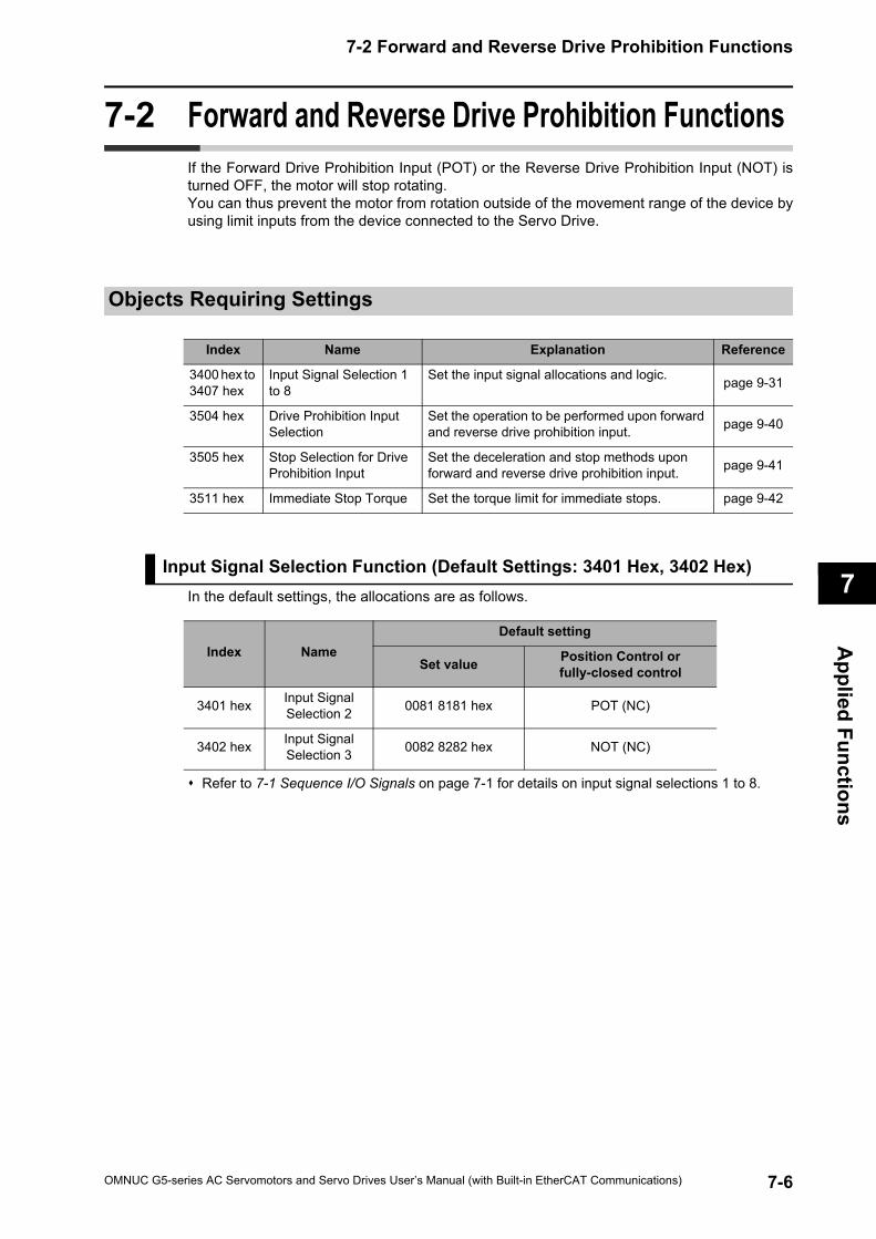
7
7-2 Forward and Reverse Drive Prohibition FunctionsA
pplied Functions
7-2 Forward and Reverse Drive Prohibition FunctionsIf the Forward Drive Prohibition Input (POT) or the Reverse Drive Prohibition Input (NOT) isturned OFF, the motor will stop rotating.You can thus prevent the motor from rotation outside of the movement range of the device byusing limit inputs from the device connected to the Servo Drive.
Objects Requiring Settings
Input Signal Selection Function (Default Settings: 3401 Hex, 3402 Hex)In the default settings, the allocations are as follows.
Refer to 7-1 Sequence I/O Signals on page 7-1 for details on input signal selections 1 to 8.
Index Name Explanation Reference
3400 hex to 3407 hex
Input Signal Selection 1 to 8
Set the input signal allocations and logic. page 9-31
3504 hex Drive Prohibition Input Selection
Set the operation to be performed upon forward and reverse drive prohibition input. page 9-40
3505 hex Stop Selection for Drive Prohibition Input
Set the deceleration and stop methods upon forward and reverse drive prohibition input. page 9-41
3511 hex Immediate Stop Torque Set the torque limit for immediate stops. page 9-42
Index NameDefault setting
Set value Position Control or fully-closed control
3401 hex Input Signal Selection 2 0081 8181 hex POT (NC)
3402 hex Input Signal Selection 3 0082 8282 hex NOT (NC)
7-6OMNUC G5-series AC Servomotors and Servo Drives User’s Manual (with Built-in EtherCAT Communications)
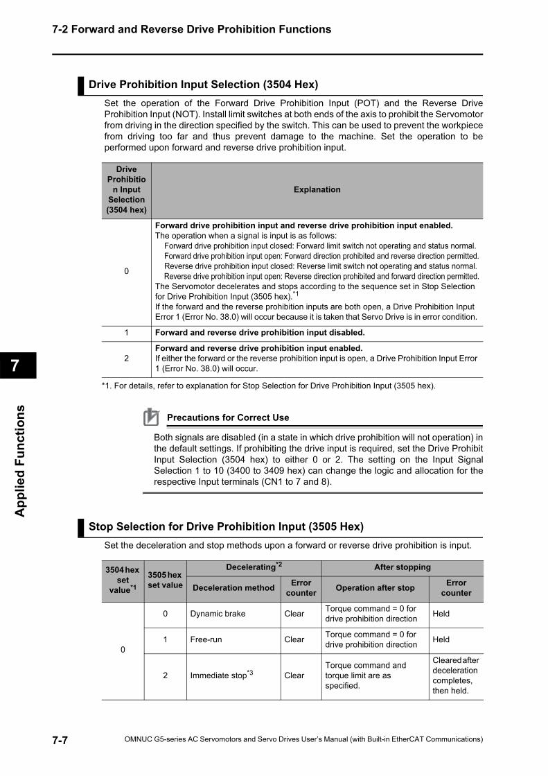
7-2 Forward and Reverse Drive Prohibition Functions
7
App
lied
Func
tions
Drive Prohibition Input Selection (3504 Hex)Set the operation of the Forward Drive Prohibition Input (POT) and the Reverse DriveProhibition Input (NOT). Install limit switches at both ends of the axis to prohibit the Servomotorfrom driving in the direction specified by the switch. This can be used to prevent the workpiecefrom driving too far and thus prevent damage to the machine. Set the operation to beperformed upon forward and reverse drive prohibition input.
Stop Selection for Drive Prohibition Input (3505 Hex)Set the deceleration and stop methods upon a forward or reverse drive prohibition is input.
Drive Prohibitio
n Input Selection (3504 hex)
Explanation
0
Forward drive prohibition input and reverse drive prohibition input enabled.The operation when a signal is input is as follows: Forward drive prohibition input closed: Forward limit switch not operating and status normal. Forward drive prohibition input open: Forward direction prohibited and reverse direction permitted. Reverse drive prohibition input closed: Reverse limit switch not operating and status normal. Reverse drive prohibition input open: Reverse direction prohibited and forward direction permitted.The Servomotor decelerates and stops according to the sequence set in Stop Selection for Drive Prohibition Input (3505 hex).*1If the forward and the reverse prohibition inputs are both open, a Drive Prohibition Input Error 1 (Error No. 38.0) will occur because it is taken that Servo Drive is in error condition.
1 Forward and reverse drive prohibition input disabled.
2Forward and reverse drive prohibition input enabled.If either the forward or the reverse prohibition input is open, a Drive Prohibition Input Error 1 (Error No. 38.0) will occur.
*1. For details, refer to explanation for Stop Selection for Drive Prohibition Input (3505 hex).
Precautions for Correct Use
Both signals are disabled (in a state in which drive prohibition will not operation) inthe default settings. If prohibiting the drive input is required, set the Drive ProhibitInput Selection (3504 hex) to either 0 or 2. The setting on the Input SignalSelection 1 to 10 (3400 to 3409 hex) can change the logic and allocation for therespective Input terminals (CN1 to 7 and 8).
3504 hex set
value*1
3505 hex set value
Decelerating*2 After stopping
Deceleration method Error counter Operation after stop Error
counter
0
0 Dynamic brake Clear Torque command = 0 for drive prohibition direction Held
1 Free-run Clear Torque command = 0 for drive prohibition direction Held
2 Immediate stop*3 ClearTorque command and torque limit are as specified.
Cleared after deceleration completes, then held.
7-7 OMNUC G5-series AC Servomotors and Servo Drives User’s Manual (with Built-in EtherCAT Communications)
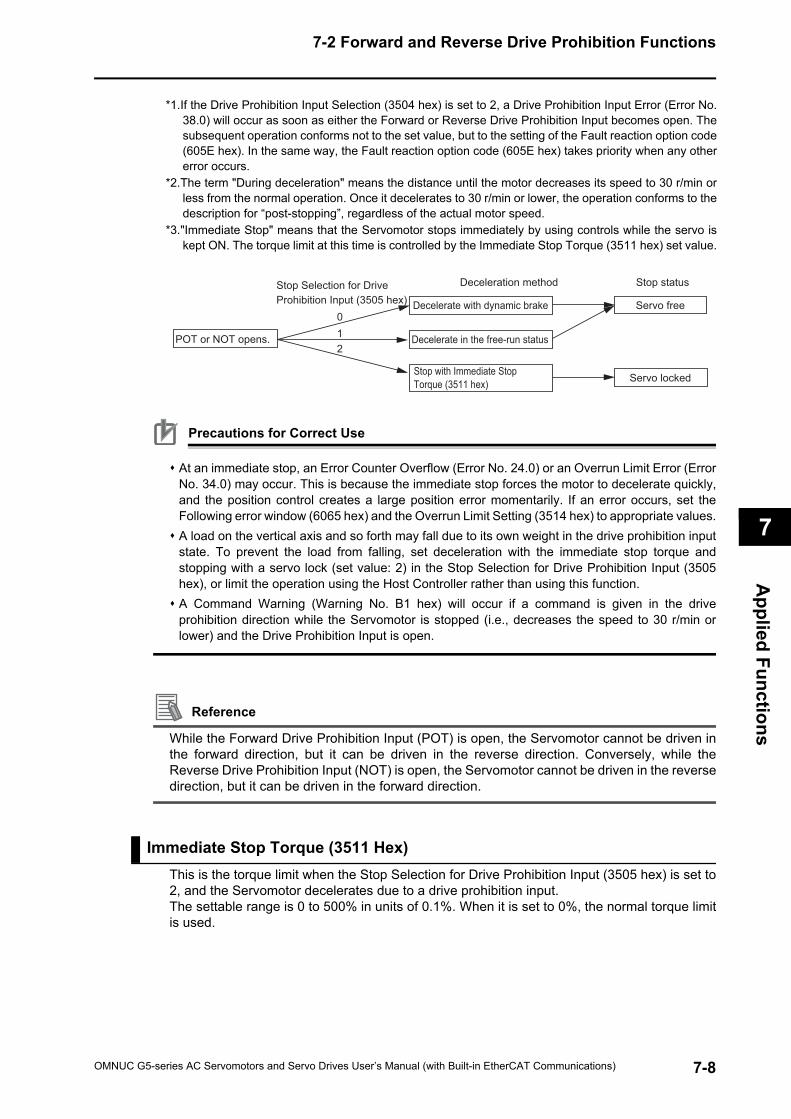
7
7-2 Forward and Reverse Drive Prohibition FunctionsA
pplied Functions
Precautions for Correct Use
At an immediate stop, an Error Counter Overflow (Error No. 24.0) or an Overrun Limit Error (ErrorNo. 34.0) may occur. This is because the immediate stop forces the motor to decelerate quickly,and the position control creates a large position error momentarily. If an error occurs, set theFollowing error window (6065 hex) and the Overrun Limit Setting (3514 hex) to appropriate values.A load on the vertical axis and so forth may fall due to its own weight in the drive prohibition inputstate. To prevent the load from falling, set deceleration with the immediate stop torque andstopping with a servo lock (set value: 2) in the Stop Selection for Drive Prohibition Input (3505hex), or limit the operation using the Host Controller rather than using this function.A Command Warning (Warning No. B1 hex) will occur if a command is given in the driveprohibition direction while the Servomotor is stopped (i.e., decreases the speed to 30 r/min orlower) and the Drive Prohibition Input is open.
Reference
While the Forward Drive Prohibition Input (POT) is open, the Servomotor cannot be driven inthe forward direction, but it can be driven in the reverse direction. Conversely, while theReverse Drive Prohibition Input (NOT) is open, the Servomotor cannot be driven in the reversedirection, but it can be driven in the forward direction.
Immediate Stop Torque (3511 Hex)This is the torque limit when the Stop Selection for Drive Prohibition Input (3505 hex) is set to2, and the Servomotor decelerates due to a drive prohibition input.The settable range is 0 to 500% in units of 0.1%. When it is set to 0%, the normal torque limitis used.
*1.If the Drive Prohibition Input Selection (3504 hex) is set to 2, a Drive Prohibition Input Error (Error No.38.0) will occur as soon as either the Forward or Reverse Drive Prohibition Input becomes open. Thesubsequent operation conforms not to the set value, but to the setting of the Fault reaction option code(605E hex). In the same way, the Fault reaction option code (605E hex) takes priority when any othererror occurs.
*2.The term "During deceleration" means the distance until the motor decreases its speed to 30 r/min orless from the normal operation. Once it decelerates to 30 r/min or lower, the operation conforms to thedescription for “post-stopping”, regardless of the actual motor speed.
*3."Immediate Stop" means that the Servomotor stops immediately by using controls while the servo iskept ON. The torque limit at this time is controlled by the Immediate Stop Torque (3511 hex) set value.
Stop Selection for DriveProhibition Input (3505 hex)
POT or NOT opens.
Deceleration method
Decelerate with dynamic brake
Decelerate in the free-run status
Stop status
Servo free
Servo locked
012
Stop with Immediate Stop Torque (3511 hex)
7-8OMNUC G5-series AC Servomotors and Servo Drives User’s Manual (with Built-in EtherCAT Communications)
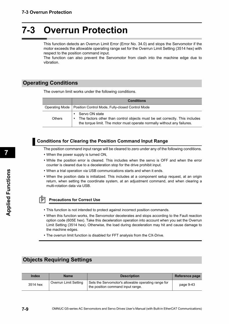
7-3 Overrun Protection
7
App
lied
Func
tions
7-3 Overrun ProtectionThis function detects an Overrun Limit Error (Error No. 34.0) and stops the Servomotor if themotor exceeds the allowable operating range set for the Overrun Limit Setting (3514 hex) withrespect to the position command input.The function can also prevent the Servomotor from clash into the machine edge due tovibration.
Operating ConditionsThe overrun limit works under the following conditions.
Conditions for Clearing the Position Command Input RangeThe position command input range will be cleared to zero under any of the following conditions.
When the power supply is turned ON,While the position error is cleared. This includes when the servo is OFF and when the errorcounter is cleared due to a deceleration stop for the drive prohibit input.When a trial operation via USB communications starts and when it ends.When the position data is initialized. This includes at a component setup request, at an originreturn, when setting the coordinate system, at an adjustment command, and when clearing amulti-rotation data via USB.
Precautions for Correct Use
This function is not intended to protect against incorrect position commands.When this function works, the Servomotor decelerates and stops according to the Fault reactionoption code (605E hex). Take this deceleration operation into account when you set the OverrunLimit Setting (3514 hex). Otherwise, the load during deceleration may hit and cause damage tothe machine edges. The overrun limit function is disabled for FFT analysis from the CX-Drive.
Objects Requiring Settings
Conditions
Operating Mode Position Control Mode, Fully-closed Control Mode
OthersServo ON stateThe factors other than control objects must be set correctly. This includesthe torque limit. The motor must operate normally without any failures.
Index Name Description Reference page
3514 hex Overrun Limit Setting Sets the Servomotor's allowable operating range for the position command input range. page 9-43
7-9 OMNUC G5-series AC Servomotors and Servo Drives User’s Manual (with Built-in EtherCAT Communications)
7
7-3 Overrun ProtectionA
pplied Functions
Operation Example
No Position Command Input (Servo ON)No position command is entered. The Servomotor's allowable operating range is the range setin object 3514 hex on both the right and left. An overrun limit error will occur (Error No. 34.0) ifthe load enters the error range, or the shaded area in the drawing below, due to vibration.
Right Side Operation (Servo ON)When a rightward position command is entered, the Servomotor's allowable operating rangeincreases for the commanded amount. The range will be the result where the rotation set for3514 hex is added on both sides for the position command.
Left Side Operation (Servo ON)When a leftward position command is entered, the Servomotor's allowable operating rangefurther increases.
Servomotor Load
Servomotor's allowableoperating range
Error range (Error No. 34.0) Error range (Error No. 34.0)
3514 hex 3514 hex
Servomotor Load
Servomotor's allowableoperating range
Entered positioncommand range3514 hex 3514 hex
Error range (Error No. 34.0)
Error range (Error No.34.0)
Servomotor Load
Servomotor's allowable operating range
Entered positioncommand range
Error range (Error No.34.0)
Error range (Error No.34.0)
3514 hex 3514 hex
7-10OMNUC G5-series AC Servomotors and Servo Drives User’s Manual (with Built-in EtherCAT Communications)
7-4 Backlash Compensation
7
App
lied
Func
tions
7-4 Backlash CompensationThe function compensates for backlash for position control and fully-closed control.
Objects Requiring Settings
Backlash Compensation Selection (3704 Hex)This object is used to select whether to enable or disable backlash compensation duringposition control, and to set the compensation direction.
Setting MethodThe backlash compensation works in different directions depending on the setting in theBacklash Compensation Selection (3704 hex) and on whether the set value for the BacklashCompensation Amount (3705 hex) is positive or negative.
Index Name Description Reference page
3704 hexBacklash Compensation Selection
Select whether to enable or disable backlash compensation during position control.Set the compensation direction.
page 9-55
3705 hex Backlash Compensation Amount Set the compensation amount during position control. page 9-55
3706 hexBacklash Compensation Time Constant
Set the backlash compensation time constant during position control. page 9-55
Set value Description
0 Disable backlash compensation.
1 Compensate for backlash at the first forward operation after the servo is turned ON.
2 Compensate for backlash at the first reverse operation after the servo is turned ON.
3704 hex 3705 hex contains a positive value 3705 hex contains a negative value
1 Compensate in positive direction when operation is in forward.
Compensate in negative direction when operation is in forward.
2 Compensate positive direction when it is in reverse operation.
Compensate in negative directions when operation is in reverse.
7-11 OMNUC G5-series AC Servomotors and Servo Drives User’s Manual (with Built-in EtherCAT Communications)
7
7-4 Backlash CompensationA
pplied Functions
Precautions for Correct Use
To determine the actual position of the Servomotor, offset the Servomotor position data acquiredvia EtherCAT communications by the backlash compensation amount.Backlash compensation is performed on the first position command in the set direction after theservo is turned ON. Any prior operations in the opposite direction are not compensated. But thefirst reverse operation after the initial backlash compensation is compensated. Backlashcompensation is not performed again as long as the operation continues in the same direction.When the Servo OFF status occurs while backlash compensation is performed, the backlashcompensation amount is cleared. This is done by presetting the position command data of theServo Drive to the Servomotor position data that includes the backlash compensation amount.When the servo is turned ON again, backlash compensation is performed as described above.
Reference
Conditions for Clearing Backlash CompensationBacklash compensation is cleared to zero under any of the following conditions:
When the position error is reset. This includes when the servo is turned OFF, and when the errorcounter is reset for the drive prohibition input. When the position data is initialized, except for the homing operation in Homing mode (hm). Thisincludes Config (4100 hex) and Absolute Encoder Setup (4102 hex).
7-12OMNUC G5-series AC Servomotors and Servo Drives User’s Manual (with Built-in EtherCAT Communications)
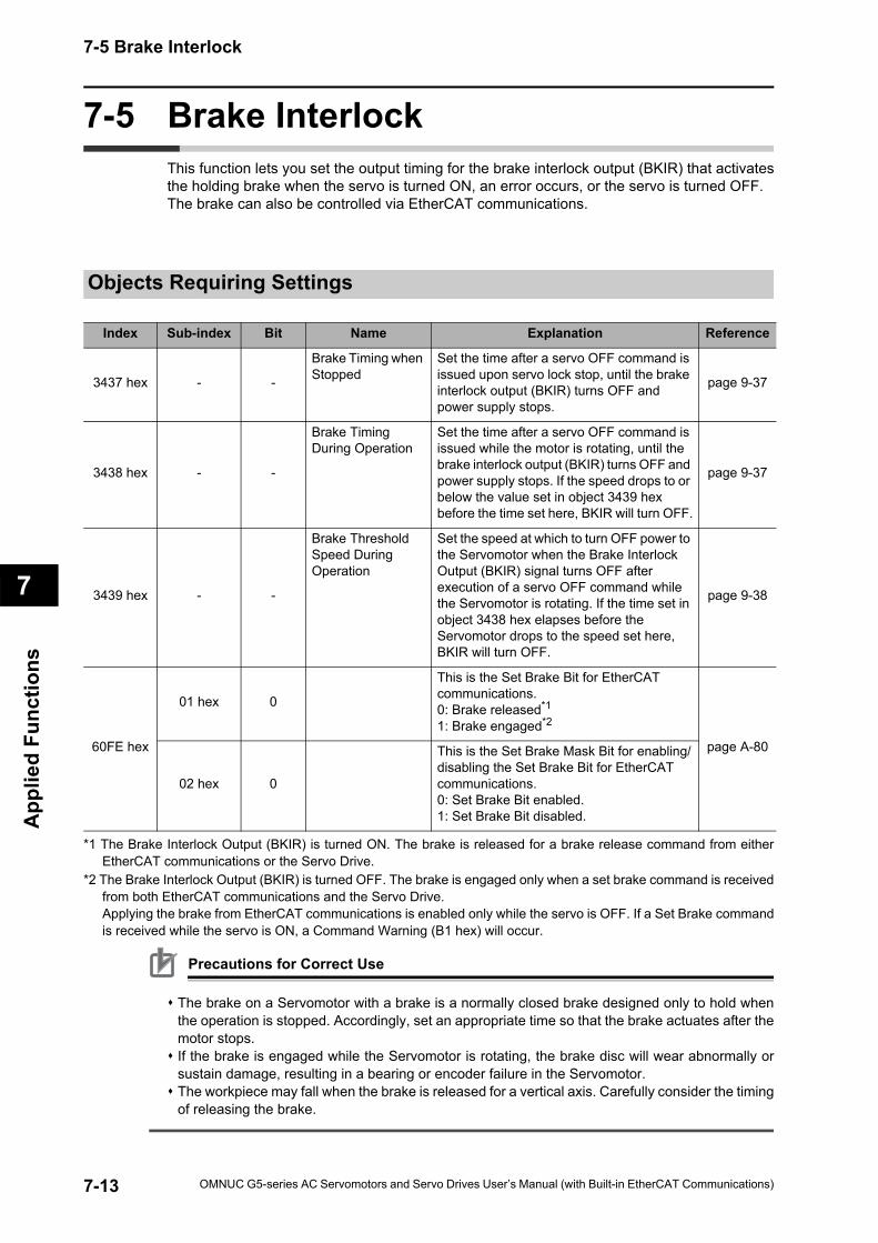
7-5 Brake Interlock
7
App
lied
Func
tions
7-5 Brake InterlockThis function lets you set the output timing for the brake interlock output (BKIR) that activatesthe holding brake when the servo is turned ON, an error occurs, or the servo is turned OFF.The brake can also be controlled via EtherCAT communications.
Objects Requiring Settings
*1 The Brake Interlock Output (BKIR) is turned ON. The brake is released for a brake release command from eitherEtherCAT communications or the Servo Drive.
*2 The Brake Interlock Output (BKIR) is turned OFF. The brake is engaged only when a set brake command is receivedfrom both EtherCAT communications and the Servo Drive. Applying the brake from EtherCAT communications is enabled only while the servo is OFF. If a Set Brake commandis received while the servo is ON, a Command Warning (B1 hex) will occur.
Precautions for Correct Use
The brake on a Servomotor with a brake is a normally closed brake designed only to hold whenthe operation is stopped. Accordingly, set an appropriate time so that the brake actuates after themotor stops.If the brake is engaged while the Servomotor is rotating, the brake disc will wear abnormally orsustain damage, resulting in a bearing or encoder failure in the Servomotor.The workpiece may fall when the brake is released for a vertical axis. Carefully consider the timingof releasing the brake.
Index Sub-index Bit Name Explanation Reference
3437 hex - -
Brake Timing when Stopped
Set the time after a servo OFF command is issued upon servo lock stop, until the brake interlock output (BKIR) turns OFF and power supply stops.
page 9-37
3438 hex - -
Brake Timing During Operation
Set the time after a servo OFF command is issued while the motor is rotating, until the brake interlock output (BKIR) turns OFF and power supply stops. If the speed drops to or below the value set in object 3439 hex before the time set here, BKIR will turn OFF.
page 9-37
3439 hex - -
Brake Threshold Speed During Operation
Set the speed at which to turn OFF power to the Servomotor when the Brake Interlock Output (BKIR) signal turns OFF after execution of a servo OFF command while the Servomotor is rotating. If the time set in object 3438 hex elapses before the Servomotor drops to the speed set here, BKIR will turn OFF.
page 9-38
60FE hex
01 hex 0
This is the Set Brake Bit for EtherCAT communications. 0: Brake released*1
1: Brake engaged*2
page A-80
02 hex 0
This is the Set Brake Mask Bit for enabling/disabling the Set Brake Bit for EtherCAT communications. 0: Set Brake Bit enabled. 1: Set Brake Bit disabled.
7-13 OMNUC G5-series AC Servomotors and Servo Drives User’s Manual (with Built-in EtherCAT Communications)
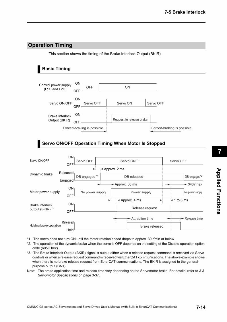
7
7-5 Brake InterlockA
pplied Functions
Operation TimingThis section shows the timing of the Brake Interlock Output (BKIR).
Basic Timing
Servo ON/OFF Operation Timing When Motor Is Stopped
*1. The servo does not turn ON until the motor rotation speed drops to approx. 30 r/min or below.*2. The operation of the dynamic brake when the servo is OFF depends on the setting of the Disable operation option
code (605C hex). *3. The Brake Interlock Output (BKIR) signal is output either when a release request command is received via Servo
controls or when a release request command is received via EtherCAT communications. The above example shows when there is no brake release request from EtherCAT communications. The BKIR is assigned to the general-purpose output (CN1).
Note: The brake application time and release time vary depending on the Servomotor brake. For details, refer to 3-3 Servomotor Specifications on page 3-37.
ON
OFF
ON
OFF
ON
OFF
OFF ON
Servo ON/OFF
Brake Interlock Output (BKIR)
Servo OFF Servo ON Servo OFF
Request to release brake
Forced-braking is possible. Forced-braking is possible.
Control power supply (L1C and L2C)
Servo ON/OFFON
OFF
Dynamic brake Released
Engaged
Motor power supplyON
OFF
ON
OFF
Approx. 2 ms
Approx. 4 ms 1 to 6 ms
Approx. 60 ms
Brake interlockoutput (BKIR) *3
Released
Held
Attraction time Release time
Servo OFF Servo OFFServo ON *1
DB engaged *1 DB engaged*2DB released
Power supplyNo power supply No power supply
3437 hex
Release request
Holding brake operation Brake released
7-14OMNUC G5-series AC Servomotors and Servo Drives User’s Manual (with Built-in EtherCAT Communications)
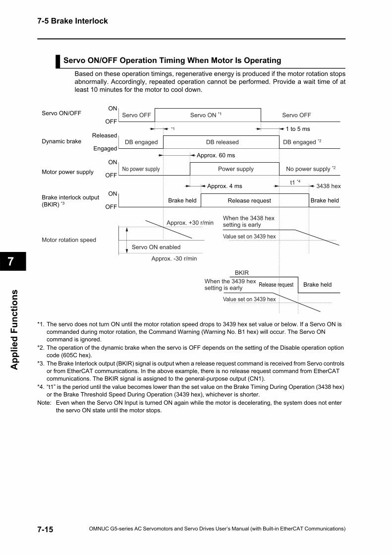
7-5 Brake Interlock
7
App
lied
Func
tions
Servo ON/OFF Operation Timing When Motor Is OperatingBased on these operation timings, regenerative energy is produced if the motor rotation stopsabnormally. Accordingly, repeated operation cannot be performed. Provide a wait time of atleast 10 minutes for the motor to cool down.
*1. The servo does not turn ON until the motor rotation speed drops to 3439 hex set value or below. If a Servo ON is commanded during motor rotation, the Command Warning (Warning No. B1 hex) will occur. The Servo ON command is ignored.
*2. The operation of the dynamic brake when the servo is OFF depends on the setting of the Disable operation option code (605C hex).
*3. The Brake Interlock output (BKIR) signal is output when a release request command is received from Servo controls or from EtherCAT communications. In the above example, there is no release request command from EtherCAT communications. The BKIR signal is assigned to the general-purpose output (CN1).
*4. “t1” is the period until the value becomes lower than the set value on the Brake Timing During Operation (3438 hex) or the Brake Threshold Speed During Operation (3439 hex), whichever is shorter.
Note: Even when the Servo ON Input is turned ON again while the motor is decelerating, the system does not enter the servo ON state until the motor stops.
Servo ON/OFFON
OFF
Dynamic brakeReleased
Engaged
Motor power supplyON
OFF
Brake interlock output (BKlR) *3
ON
OFF
*1 1 to 5 ms
Approx. 4 ms 3438 hex
Approx. 60 ms
Servo OFF Servo OFFServo ON *1
DB engaged DB engaged *2DB released
Power supplyNo power supply No power supply *2
Release requestBrake held
t1 *4
Motor rotation speedServo ON enabled
Approx. +30 r/min
Value set on 3439 hex
Approx. -30 r/min
Release request Brake held
Value set on 3439 hex
BKIR
When the 3438 hexsetting is early
Brake held
When the 3439 hexsetting is early
7-15 OMNUC G5-series AC Servomotors and Servo Drives User’s Manual (with Built-in EtherCAT Communications)
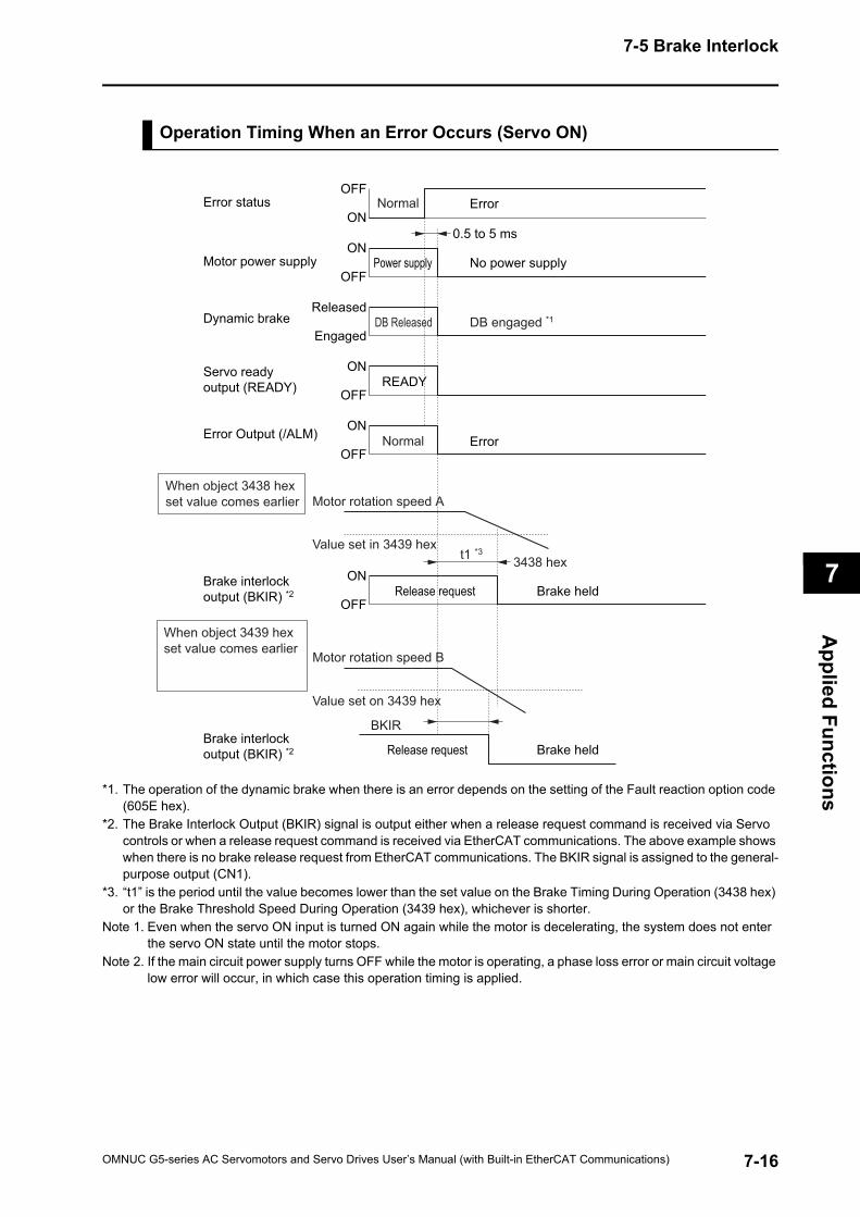
7
7-5 Brake InterlockA
pplied Functions
Operation Timing When an Error Occurs (Servo ON)
*1. The operation of the dynamic brake when there is an error depends on the setting of the Fault reaction option code (605E hex).
*2. The Brake Interlock Output (BKIR) signal is output either when a release request command is received via Servo controls or when a release request command is received via EtherCAT communications. The above example shows when there is no brake release request from EtherCAT communications. The BKIR signal is assigned to the general-purpose output (CN1).
*3. “t1” is the period until the value becomes lower than the set value on the Brake Timing During Operation (3438 hex) or the Brake Threshold Speed During Operation (3439 hex), whichever is shorter.
Note 1. Even when the servo ON input is turned ON again while the motor is decelerating, the system does not enter the servo ON state until the motor stops.
Note 2. If the main circuit power supply turns OFF while the motor is operating, a phase loss error or main circuit voltage low error will occur, in which case this operation timing is applied.
Error statusOFF
ON0.5 to 5 ms
Motor power supply
Dynamic brake
Brake interlockoutput (BKIR) *2
Brake interlockoutput (BKIR) *2
Normal Error
ON
OFFPower supply
Released
Engaged
ON
OFF
ON
OFF
ON
OFFRelease request
No power supply
DB Released DB engaged *1
READYServo readyoutput (READY)
Error Output (/ALM) Error
Brake held
3438 hext1 *3
When object 3438 hexset value comes earlier
When object 3439 hex set value comes earlier
Release request Brake held
Value set in 3439 hex
Value set on 3439 hex
Motor rotation speed A
Motor rotation speed B
BKIR
Normal
7-16OMNUC G5-series AC Servomotors and Servo Drives User’s Manual (with Built-in EtherCAT Communications)
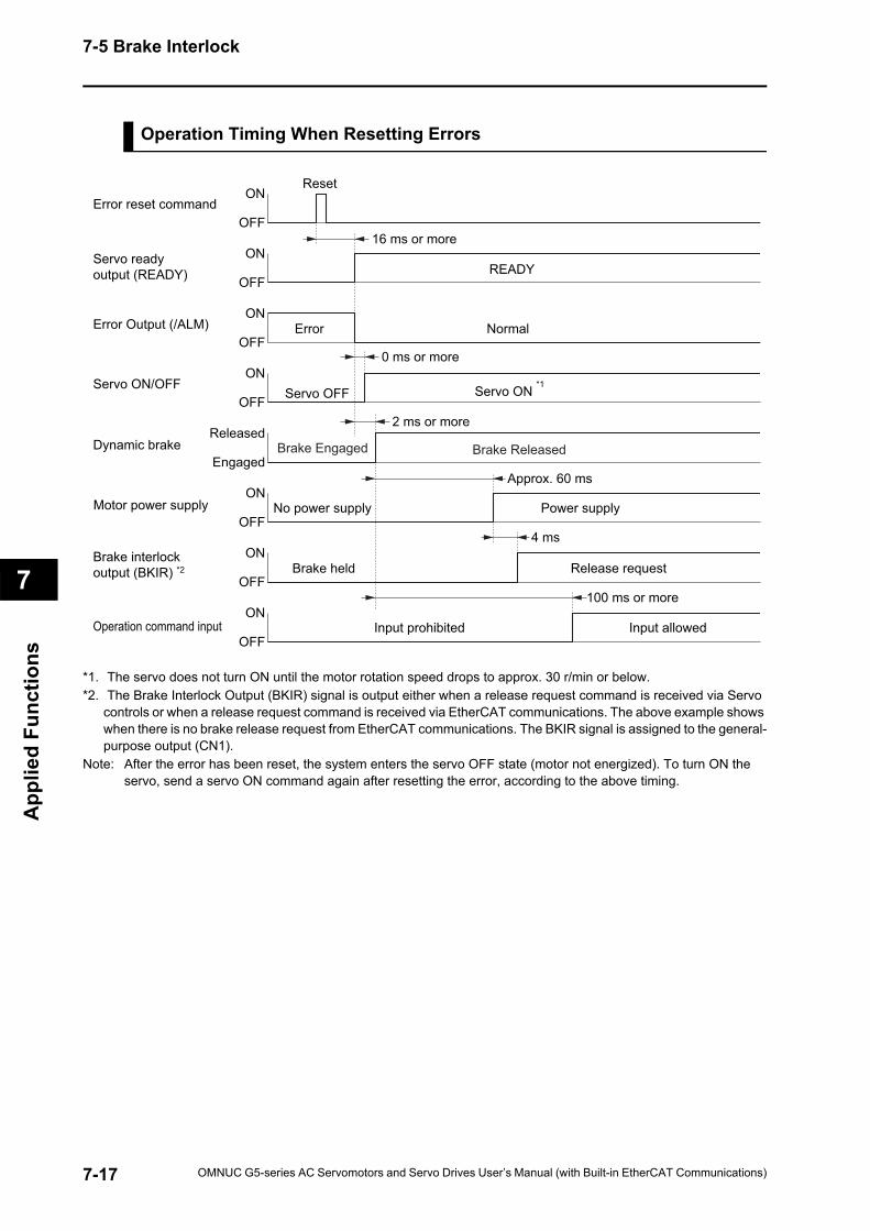
7-5 Brake Interlock
7
App
lied
Func
tions
Operation Timing When Resetting Errors
*1. The servo does not turn ON until the motor rotation speed drops to approx. 30 r/min or below.*2. The Brake Interlock Output (BKIR) signal is output either when a release request command is received via Servo
controls or when a release request command is received via EtherCAT communications. The above example shows when there is no brake release request from EtherCAT communications. The BKIR signal is assigned to the general-purpose output (CN1).
Note: After the error has been reset, the system enters the servo OFF state (motor not energized). To turn ON the servo, send a servo ON command again after resetting the error, according to the above timing.
Error reset commandON
OFF16 ms or more
Error Output (/ALM)
Reset
OFF
ON
OFF
Servo ON/OFFON
OFF
ON
Brake ReleasedBrake Engaged
READY
Released
EngagedApprox. 60 ms
Brake interlockoutput (BKIR) *2
Error Normal
OFFPower supply
ON
OFF
ON
OFF
No power supply
Servo readyoutput (READY)
Dynamic brake
Motor power supplyON
Operation command input
Servo OFF
Input prohibited Input allowed
Servo ON *1
Release requestBrake held
0 ms or more
2 ms or more
4 ms
100 ms or more
7-17 OMNUC G5-series AC Servomotors and Servo Drives User’s Manual (with Built-in EtherCAT Communications)
7
7-6 Electronic Gear FunctionA
pplied Functions
7-6 Electronic Gear FunctionThis function controls the position by using the value multiplied the position command enteredon the Host Controller by the preset electronic gear ratio. The functions is used in the PositionControl and Fully-closed Control modes. (This applies only when the communications cycle is1, 2, or 4 ms.) For communications cycles for which the electronic gear is not supported (250 or 500 µs), aFunction Setting Error (Error No. 93.4) will occur if the electronic gear is enabled. When connected to an OMRON CJ1W-NC@81/@82 Position Control Unit, the electronic gearratio is set in the Position Control Unit. Set the electronic gear ratio in the Servo Drive to 1:1.
Precautions for Correct Use
The electronic gear function is not supported for unit version 2.0. Do not change the default setting. The electronic gear function is scheduled for support from unit version 2.1.
Objects Requiring Settings
*1. The electronic gear ratio must be set between 1/1000 and 1000. If it is set outside the range, an Object Setting Error 1 (Error No. 93.0) will occur.Whether the electronic gear is enabled is determined from the setting of the objects. If the gear ratio setting is 1:1, the electronic gear is disabled.
*2. If object 6091-01 hex is set to 0, the encoder resolution is set to the numerator during fully-closed control also.
Index Sub-index Name Explanation Reference
6091 hex
01 hex Motor revolutions *1
Set the numerator of the electronic gear ratio.If the set value is 0, the encoder resolution is automatically set as the numerator. *2• 131072 for a 17-bit absolute encoder• 1048576 for a 20-bit incremental encoder page A-79
02 hex Shaft revolutions *1
Set the denominator of the electronic gear ratio.
7-18OMNUC G5-series AC Servomotors and Servo Drives User’s Manual (with Built-in EtherCAT Communications)
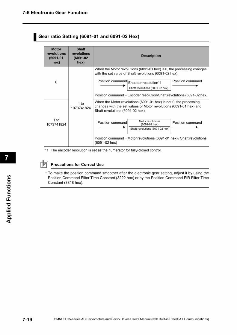
7-6 Electronic Gear Function
7
App
lied
Func
tions
Gear ratio Setting (6091-01 and 6091-02 Hex)
*1 The encoder resolution is set as the numerator for fully-closed control.
Precautions for Correct Use
To make the position command smoother after the electronic gear setting, adjust it by using thePosition Command Filter Time Constant (3222 hex) or by the Position Command FIR Filter TimeConstant (3818 hex).
Motor revolutions
(6091-01 hex)
Shaft revolutions
(6091-02 hex)
Description
0
1 to 1073741824
When the Motor revolutions (6091-01 hex) is 0, the processing changes with the set value of Shaft revolutions (6091-02 hex).
Position command = Encoder resolution/Shaft revolutions (6091-02 hex)
1 to 1073741824
When the Motor revolutions (6091-01 hex) is not 0, the processing changes with the set values of Motor revolutions (6091-01 hex) and Shaft revolutions (6091-02 hex).
Position command = Motor revolutions (6091-01 hex) / Shaft revolutions (6091-02 hex)
Position command Encoder resolution*1 Shaft revolutions (6091-02 hex)
Position command
Position command Motor revolutions (6091-01 hex)
Shaft revolutions (6091-02 hex)
Position command
7-19 OMNUC G5-series AC Servomotors and Servo Drives User’s Manual (with Built-in EtherCAT Communications)
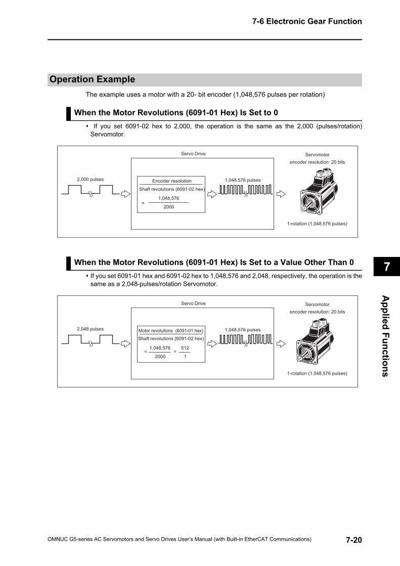
7
7-6 Electronic Gear FunctionA
pplied Functions
Operation ExampleThe example uses a motor with a 20- bit encoder (1,048,576 pulses per rotation)
When the Motor Revolutions (6091-01 Hex) Is Set to 0 If you set 6091-02 hex to 2,000, the operation is the same as the 2,000 (pulses/rotation)Servomotor.
When the Motor Revolutions (6091-01 Hex) Is Set to a Value Other Than 0If you set 6091-01 hex and 6091-02 hex to 1,048,576 and 2,048, respectively, the operation is thesame as a 2,048-pulses/rotation Servomotor.
Encoder resolution
Shaft revolutions (6091-02 hex)
1,048,576
2000=
Servo Drive
1,048,576 pulses2,000 pulses
Servomotorencoder resolution: 20 bits
1-rotation (1,048,576 pulses)
Motor revolutions (6091-01 hex)
Shaft revolutions (6091-02 hex)
1,048,576
2000= =
512
1
Servo Drive
1,048,576 pulses2,048 pulses
Servomotorencoder resolution: 20 bits
1-rotation (1,048,576 pulses)
7-20OMNUC G5-series AC Servomotors and Servo Drives User’s Manual (with Built-in EtherCAT Communications)
7-7 Torque Limit Switching
7
App
lied
Func
tions
7-7 Torque Limit SwitchingThis function switches the torque limit according to the operation direction, and depending onthe Forward External Torque Limit (PCL), the Reverse External Torque Limit (NCL), and theForward/Reverse Torque Limit Input Commands from EtherCAT communications.This function is used in the following conditions.
• When push-motion operation, such as pressing, is performed.• When the torque at startup and during deceleration should be suppressed to protect the
mechanical system, etc.The Torque Limit Selection (3521 hex) is used to select a method to switch the torque limit.
Operating ConditionsThe torque limit switching function works under the following conditions.
Objects Requiring Settings
Conditions
Operation mode Position Control Mode, Speed Control Mode, Torque Control Mode, or Fully-closed Control Mode
OthersServo ON stateThe factors other than control objects must be set correctly. This includes thetorque limit. The motor must operate normally without any failures.
Index Name Explanation Reference
3521 hex Torque Limit Selection Select the torque limit based on the various objects and input signals. page 9-44
60E0 hex Positive torque limit value Set the forward torque limit value. page A-57
60E1 hex Negative torque limit value Set the reverse torque limit value. page A-57
3525 hex Forward External Torque Limit Set the forward torque limit for a network signal. page 9-45
3526 hex Reverse External Torque Limit Set the reverse torque limit for a network signal. page 9-45
7-21 OMNUC G5-series AC Servomotors and Servo Drives User’s Manual (with Built-in EtherCAT Communications)
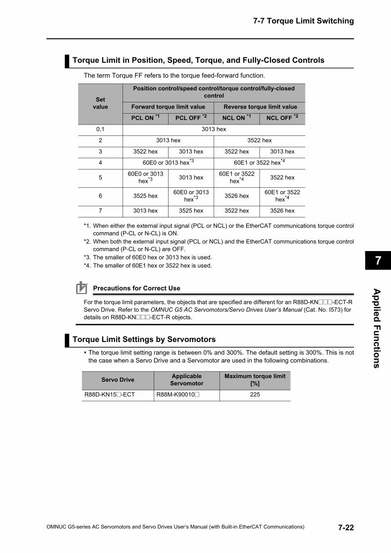
7
7-7 Torque Limit SwitchingA
pplied Functions
Torque Limit in Position, Speed, Torque, and Fully-Closed Controls
The term Torque FF refers to the torque feed-forward function.
*1. When either the external input signal (PCL or NCL) or the EtherCAT communications torque controlcommand (P-CL or N-CL) is ON.
*2. When both the external input signal (PCL or NCL) and the EtherCAT communications torque controlcommand (P-CL or N-CL) are OFF.
*3. The smaller of 60E0 hex or 3013 hex is used.*4. The smaller of 60E1 hex or 3522 hex is used.
Precautions for Correct Use
For the torque limit parameters, the objects that are specified are different for an R88D-KN@@@-ECT-R Servo Drive. Refer to the OMNUC G5 AC Servomotors/Servo Drives User’s Manual (Cat. No. I573) for details on R88D-KN@@@-ECT-R objects.
Torque Limit Settings by ServomotorsThe torque limit setting range is between 0% and 300%. The default setting is 300%. This is notthe case when a Servo Drive and a Servomotor are used in the following combinations.
Setvalue
Position control/speed control/torque control/fully-closed control
Forward torque limit value Reverse torque limit value
PCL ON *1 PCL OFF *2 NCL ON *1 NCL OFF *2
0,1 3013 hex
2 3013 hex 3522 hex
3 3522 hex 3013 hex 3522 hex 3013 hex
4 60E0 or 3013 hex*3 60E1 or 3522 hex*4
5 60E0 or 3013 hex*3 3013 hex 60E1 or 3522
hex*4 3522 hex
6 3525 hex 60E0 or 3013 hex*3 3526 hex 60E1 or 3522
hex*4
7 3013 hex 3525 hex 3522 hex 3526 hex
Servo Drive Applicable Servomotor
Maximum torque limit [%]
R88D-KN15@-ECT R88M-K90010@ 225
7-22OMNUC G5-series AC Servomotors and Servo Drives User’s Manual (with Built-in EtherCAT Communications)
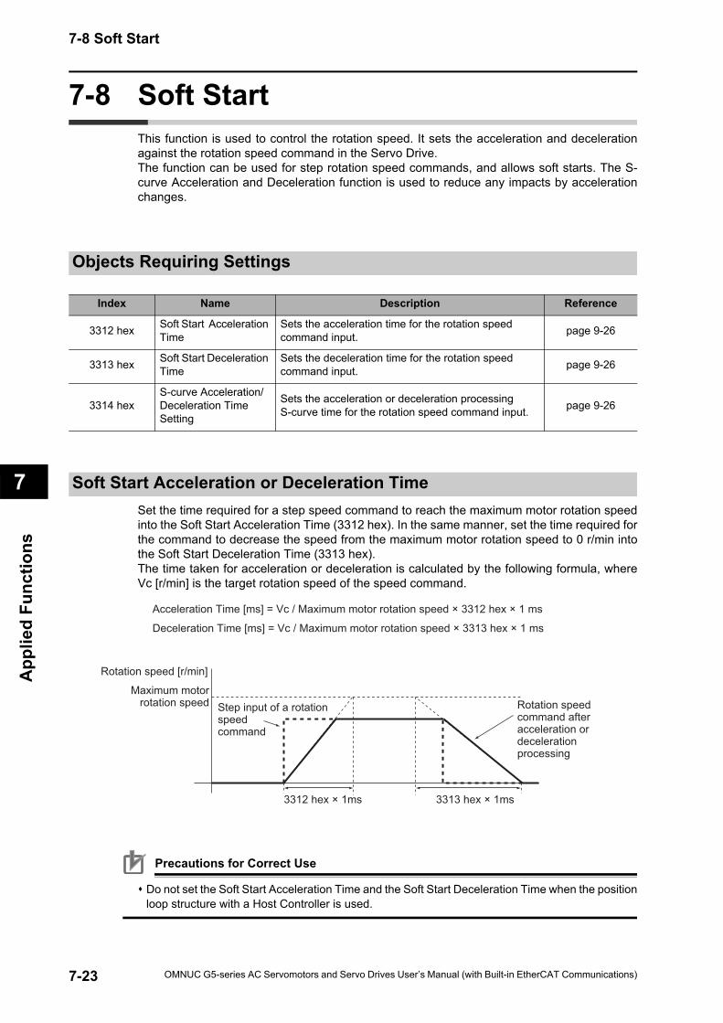
7-8 Soft Start
7
App
lied
Func
tions
7-8 Soft StartThis function is used to control the rotation speed. It sets the acceleration and decelerationagainst the rotation speed command in the Servo Drive. The function can be used for step rotation speed commands, and allows soft starts. The S-curve Acceleration and Deceleration function is used to reduce any impacts by accelerationchanges.
Objects Requiring Settings
Soft Start Acceleration or Deceleration TimeSet the time required for a step speed command to reach the maximum motor rotation speedinto the Soft Start Acceleration Time (3312 hex). In the same manner, set the time required forthe command to decrease the speed from the maximum motor rotation speed to 0 r/min intothe Soft Start Deceleration Time (3313 hex). The time taken for acceleration or deceleration is calculated by the following formula, whereVc [r/min] is the target rotation speed of the speed command.
Precautions for Correct Use
Do not set the Soft Start Acceleration Time and the Soft Start Deceleration Time when the positionloop structure with a Host Controller is used.
Index Name Description Reference
3312 hex Soft Start Acceleration Time
Sets the acceleration time for the rotation speed command input. page 9-26
3313 hex Soft Start Deceleration Time
Sets the deceleration time for the rotation speed command input. page 9-26
3314 hexS-curve Acceleration/Deceleration Time Setting
Sets the acceleration or deceleration processing S-curve time for the rotation speed command input. page 9-26
Acceleration Time [ms] = Vc / Maximum motor rotation speed × 3312 hex × 1 ms
Deceleration Time [ms] = Vc / Maximum motor rotation speed × 3313 hex × 1 ms
Rotation speed [r/min]
Maximum motorrotation speed Step input of a rotation
speed command
Rotation speed command after acceleration or deceleration processing
3312 hex × 1ms 3313 hex × 1ms
7-23 OMNUC G5-series AC Servomotors and Servo Drives User’s Manual (with Built-in EtherCAT Communications)
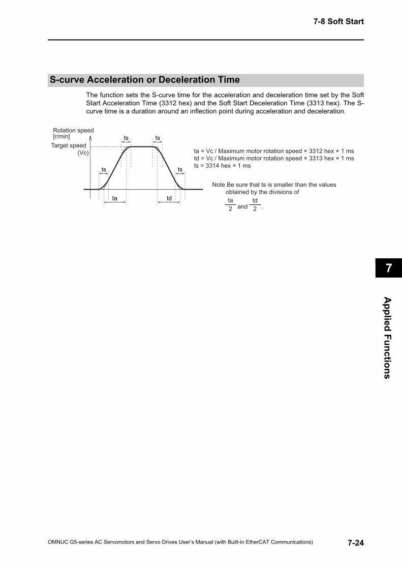
7
7-8 Soft StartA
pplied Functions
S-curve Acceleration or Deceleration TimeThe function sets the S-curve time for the acceleration and deceleration time set by the SoftStart Acceleration Time (3312 hex) and the Soft Start Deceleration Time (3313 hex). The S-curve time is a duration around an inflection point during acceleration and deceleration.
ta td
ts ts
tstsRotation speed [r/min]
Target speed (Vc) ta = Vc / Maximum motor rotation speed × 3312 hex × 1 ms
td = Vc / Maximum motor rotation speed × 3313 hex × 1 msts = 3314 hex × 1 ms
Note Be sure that ts is smaller than the values obtained by the divisions of and .2
ta2td
7-24OMNUC G5-series AC Servomotors and Servo Drives User’s Manual (with Built-in EtherCAT Communications)
7-9 Gain Switching Function
7
App
lied
Func
tions
7-9 Gain Switching FunctionThis function switches the position loop and speed loop gain.Select enable or disable using Gain Switching Input Operating Mode Selection (3114 hex). Setthe switching condition using the gain switching setting.If the load inertia changes or you want to change the responsiveness depending on whetherthe motor is stopping or operating, you can perform optimal control by using gain switching.The function is used when the realtime autotuning does not work effectively, such as:
• When the load inertia fluctuates in 200 ms or less.• When the motor rotation speed does not exceed 500 r/min, or load torque does not exceed
50% of the rated torque.• When an external force is constantly applied, as with a vertical axis.
Precautions for Correct Use
When Gain 2 has been selected, realtime autotuning does not operate normally. If using the gainswitching, set the Realtime Autotuning to "Disabled" (3002 hex = 0).
7-25 OMNUC G5-series AC Servomotors and Servo Drives User’s Manual (with Built-in EtherCAT Communications)
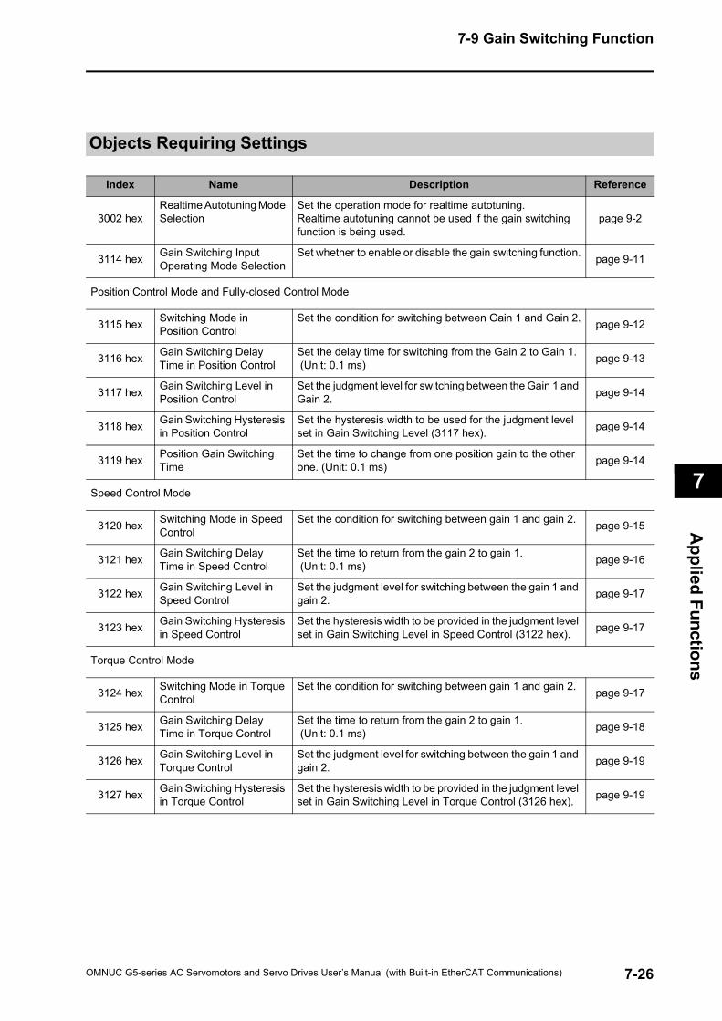
7
7-9 Gain Switching FunctionA
pplied Functions
Objects Requiring Settings
Index Name Description Reference
3002 hexRealtime Autotuning Mode Selection
Set the operation mode for realtime autotuning.Realtime autotuning cannot be used if the gain switching function is being used.
page 9-2
3114 hex Gain Switching Input Operating Mode Selection
Set whether to enable or disable the gain switching function. page 9-11
Position Control Mode and Fully-closed Control Mode
3115 hex Switching Mode in Position Control
Set the condition for switching between Gain 1 and Gain 2. page 9-12
3116 hex Gain Switching Delay Time in Position Control
Set the delay time for switching from the Gain 2 to Gain 1. (Unit: 0.1 ms) page 9-13
3117 hex Gain Switching Level in Position Control
Set the judgment level for switching between the Gain 1 and Gain 2. page 9-14
3118 hex Gain Switching Hysteresis in Position Control
Set the hysteresis width to be used for the judgment level set in Gain Switching Level (3117 hex). page 9-14
3119 hex Position Gain Switching Time
Set the time to change from one position gain to the other one. (Unit: 0.1 ms) page 9-14
Speed Control Mode
3120 hex Switching Mode in Speed Control
Set the condition for switching between gain 1 and gain 2. page 9-15
3121 hex Gain Switching Delay Time in Speed Control
Set the time to return from the gain 2 to gain 1. (Unit: 0.1 ms) page 9-16
3122 hex Gain Switching Level in Speed Control
Set the judgment level for switching between the gain 1 and gain 2. page 9-17
3123 hex Gain Switching Hysteresis in Speed Control
Set the hysteresis width to be provided in the judgment level set in Gain Switching Level in Speed Control (3122 hex). page 9-17
Torque Control Mode
3124 hex Switching Mode in Torque Control
Set the condition for switching between gain 1 and gain 2. page 9-17
3125 hex Gain Switching Delay Time in Torque Control
Set the time to return from the gain 2 to gain 1. (Unit: 0.1 ms) page 9-18
3126 hex Gain Switching Level in Torque Control
Set the judgment level for switching between the gain 1 and gain 2. page 9-19
3127 hex Gain Switching Hysteresis in Torque Control
Set the hysteresis width to be provided in the judgment level set in Gain Switching Level in Torque Control (3126 hex). page 9-19
7-26OMNUC G5-series AC Servomotors and Servo Drives User’s Manual (with Built-in EtherCAT Communications)
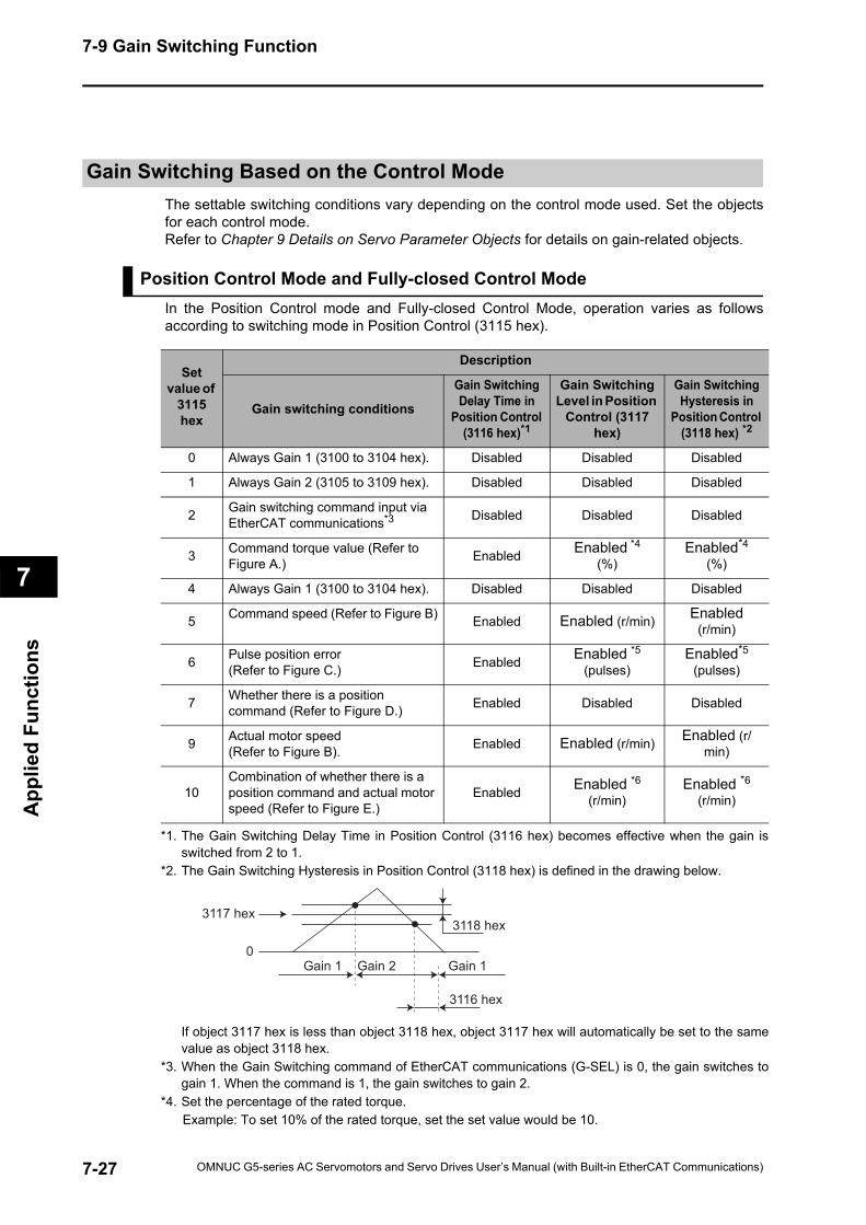
7-9 Gain Switching Function
7
App
lied
Func
tions
Gain Switching Based on the Control ModeThe settable switching conditions vary depending on the control mode used. Set the objectsfor each control mode.Refer to Chapter 9 Details on Servo Parameter Objects for details on gain-related objects.
Position Control Mode and Fully-closed Control ModeIn the Position Control mode and Fully-closed Control Mode, operation varies as followsaccording to switching mode in Position Control (3115 hex).
Set value of
3115 hex
Description
Gain switching conditions
Gain Switching Delay Time in
Position Control (3116 hex)*1
Gain Switching Level in Position
Control (3117 hex)
Gain Switching Hysteresis in
Position Control (3118 hex) *2
0 Always Gain 1 (3100 to 3104 hex). Disabled Disabled Disabled
1 Always Gain 2 (3105 to 3109 hex). Disabled Disabled Disabled
2 Gain switching command input via EtherCAT communications*3 Disabled Disabled Disabled
3 Command torque value (Refer to Figure A.) Enabled Enabled *4
(%)Enabled*4
(%)
4 Always Gain 1 (3100 to 3104 hex). Disabled Disabled Disabled
5 Command speed (Refer to Figure B) Enabled Enabled (r/min) Enabled (r/min)
6 Pulse position error (Refer to Figure C.) Enabled Enabled *5
(pulses)Enabled*5
(pulses)
7 Whether there is a position command (Refer to Figure D.) Enabled Disabled Disabled
9 Actual motor speed (Refer to Figure B). Enabled Enabled (r/min) Enabled (r/
min)
10Combination of whether there is a position command and actual motor speed (Refer to Figure E.)
Enabled Enabled *6(r/min)
Enabled *6(r/min)
*1. The Gain Switching Delay Time in Position Control (3116 hex) becomes effective when the gain isswitched from 2 to 1.
*2. The Gain Switching Hysteresis in Position Control (3118 hex) is defined in the drawing below.
If object 3117 hex is less than object 3118 hex, object 3117 hex will automatically be set to the samevalue as object 3118 hex.
*3. When the Gain Switching command of EtherCAT communications (G-SEL) is 0, the gain switches togain 1. When the command is 1, the gain switches to gain 2.
*4. Set the percentage of the rated torque. Example: To set 10% of the rated torque, set the set value would be 10.
3117 hex
0
3118 hex
3116 hex
Gain 1 Gain 2 Gain 1
7-27 OMNUC G5-series AC Servomotors and Servo Drives User’s Manual (with Built-in EtherCAT Communications)
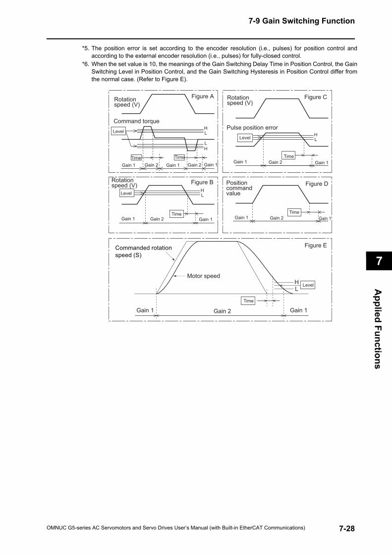
7
7-9 Gain Switching FunctionA
pplied Functions
*5. The position error is set according to the encoder resolution (i.e., pulses) for position control andaccording to the external encoder resolution (i.e., pulses) for fully-closed control.
*6. When the set value is 10, the meanings of the Gain Switching Delay Time in Position Control, the GainSwitching Level in Position Control, and the Gain Switching Hysteresis in Position Control differ fromthe normal case. (Refer to Figure E).
Figure A
Command torque
Figure C
Time
Figure D
Figure E
Gain 1 Gain 1Gain 2Time
Figure B
Rotation speed (V)
Gain 1Gain 2Time
Commanded rotation speed (S)
Gain 1 Gain 2
Time
Gain 1
Level
HL
HL
HL
HL
Pulse position error
Position command value
Motor speedHL
Level
Level
Time Time
Level
Gain 1 Gain 1Gain 2Gain 1 Gain 1 Gain 1
Gain 1
Gain 2 Gain 2
Rotation speed (V)
Rotation speed (V)
7-28OMNUC G5-series AC Servomotors and Servo Drives User’s Manual (with Built-in EtherCAT Communications)
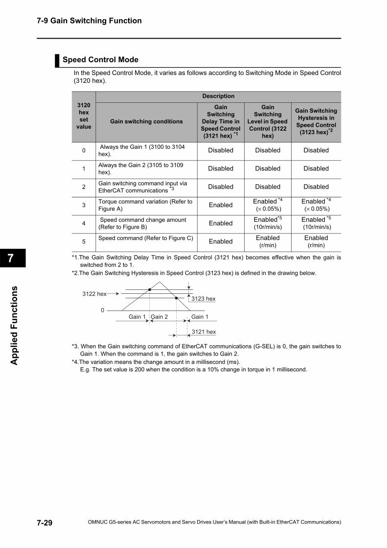
7-9 Gain Switching Function
7
App
lied
Func
tions
Speed Control ModeIn the Speed Control Mode, it varies as follows according to Switching Mode in Speed Control(3120 hex).
3120 hex set
value
Description
Gain switching conditions
Gain Switching
Delay Time in Speed Control (3121 hex) *1
Gain Switching
Level in Speed Control (3122
hex)
Gain Switching Hysteresis in
Speed Control (3123 hex)*2
0 Always the Gain 1 (3100 to 3104 hex). Disabled Disabled Disabled
1 Always the Gain 2 (3105 to 3109 hex). Disabled Disabled Disabled
2 Gain switching command input via EtherCAT communications *3 Disabled Disabled Disabled
3 Torque command variation (Refer to Figure A) Enabled Enabled *4
(× 0.05%)Enabled *4
(× 0.05%)
4 Speed command change amount (Refer to Figure B) Enabled Enabled*5
(10r/min/s)Enabled *5
(10r/min/s)
5 Speed command (Refer to Figure C) Enabled Enabled (r/min)
Enabled (r/min)
*1.The Gain Switching Delay Time in Speed Control (3121 hex) becomes effective when the gain isswitched from 2 to 1.
*2.The Gain Switching Hysteresis in Speed Control (3123 hex) is defined in the drawing below.
*3. When the Gain switching command of EtherCAT communications (G-SEL) is 0, the gain switches toGain 1. When the command is 1, the gain switches to Gain 2.
*4.The variation means the change amount in a millisecond (ms).E.g. The set value is 200 when the condition is a 10% change in torque in 1 millisecond.
3122 hex
0
3123 hex
3121 hex
Gain 1 Gain 2 Gain 1
7-29 OMNUC G5-series AC Servomotors and Servo Drives User’s Manual (with Built-in EtherCAT Communications)
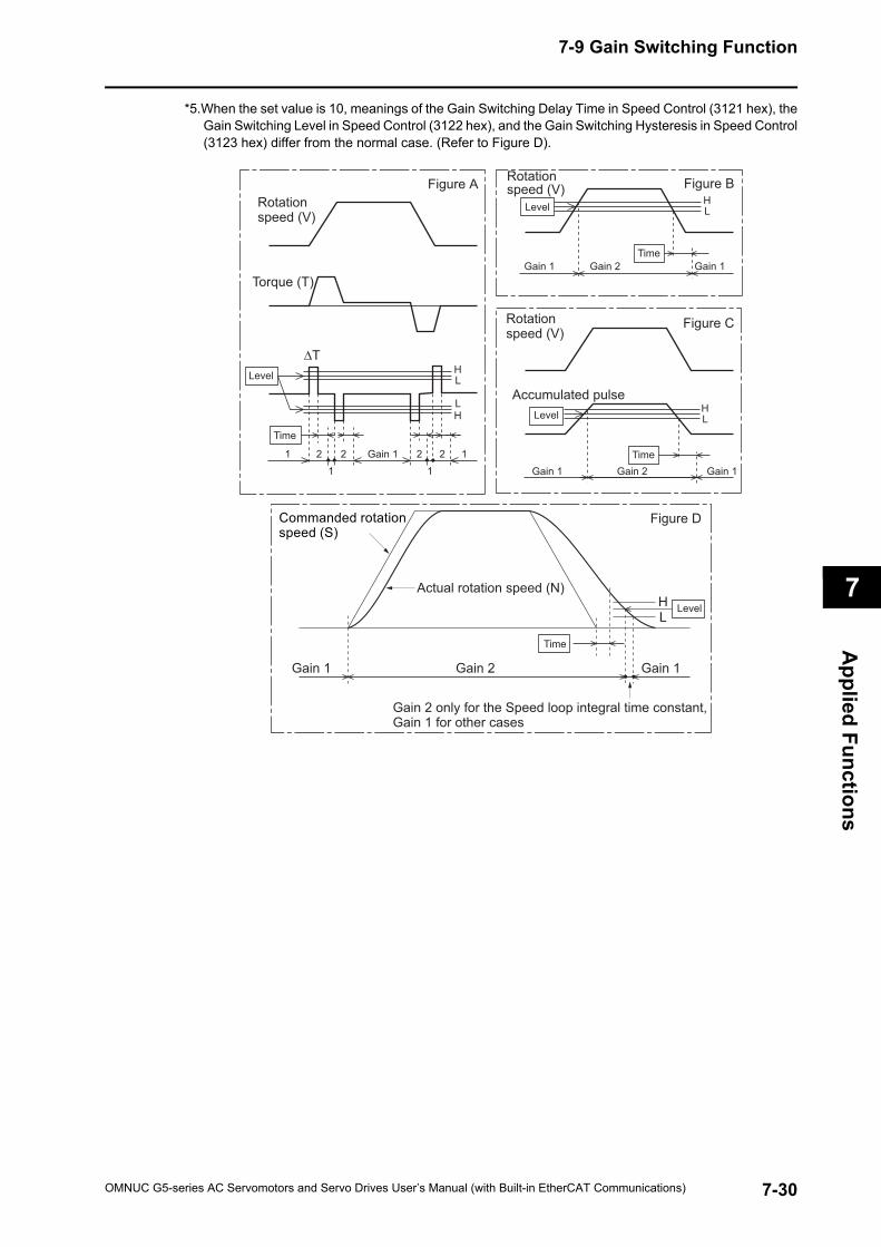
7
7-9 Gain Switching FunctionA
pplied Functions
*5.When the set value is 10, meanings of the Gain Switching Delay Time in Speed Control (3121 hex), theGain Switching Level in Speed Control (3122 hex), and the Gain Switching Hysteresis in Speed Control(3123 hex) differ from the normal case. (Refer to Figure D).
HL
HL
HL
HL
Figure ARotation speed (V)
Torque (T)
Time
11
2 2 2 21
1Gain 1
Figure CRotation speed (V)
Gain 1 Gain 1Gain 2
Accumulated pulseLevel
Time
Figure BRotation speed (V)
Gain 1 Gain 1Gain 2Time
Commanded rotation speed (S)
Gain 1 Gain 2
Actual rotation speed (N)
Time
HL
Gain 1
Gain 2 only for the Speed loop integral time constant, Gain 1 for other cases
Figure D
Level
Level
Level
7-30OMNUC G5-series AC Servomotors and Servo Drives User’s Manual (with Built-in EtherCAT Communications)
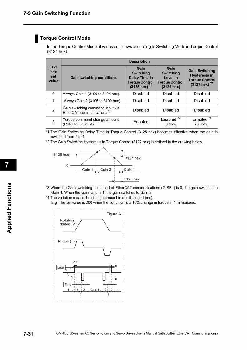
7-9 Gain Switching Function
7
App
lied
Func
tions
Torque Control ModeIn the Torque Control Mode, it varies as follows according to Switching Mode in Torque Control(3124 hex).
3124 hex set
value
Description
Gain switching conditions
Gain Switching
Delay Time in Torque Control
(3125 hex) *1
Gain Switching Level in
Torque Control (3126 hex)
Gain Switching Hysteresis in
Torque Control (3127 hex) *2
0 Always Gain 1 (3100 to 3104 hex). Disabled Disabled Disabled
1 Always Gain 2 (3105 to 3109 hex). Disabled Disabled Disabled
2 Gain switching command input via EtherCAT communications *3 Disabled Disabled Disabled
3 Torque command change amount (Refer to Figure A) Enabled Enabled *4
(0.05%)Enabled *4
(0.05%)
*1.The Gain Switching Delay Time in Torque Control (3125 hex) becomes effective when the gain isswitched from 2 to 1.
*2.The Gain Switching Hysteresis in Torque Control (3127 hex) is defined in the drawing below.
*3.When the Gain switching command of EtherCAT communications (G-SEL) is 0, the gain switches toGain 1. When the command is 1, the gain switches to Gain 2.
*4.The variation means the change amount in a millisecond (ms).E.g. The set value is 200 when the condition is a 10% change in torque in 1 millisecond.
3126 hex
0
3127 hex
3125 hex
Gain 1 Gain 2 Gain 1
HL
HL
Figure A
Rotation speed (V)
Torque (T)
Time
11
2 2 2 21
1Gain 1
Level
7-31 OMNUC G5-series AC Servomotors and Servo Drives User’s Manual (with Built-in EtherCAT Communications)
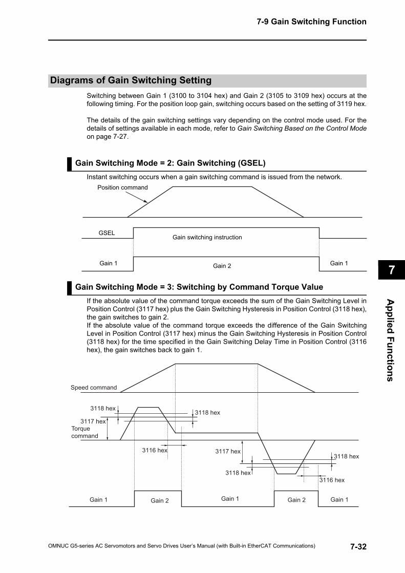
7
7-9 Gain Switching FunctionA
pplied Functions
Diagrams of Gain Switching Setting Switching between Gain 1 (3100 to 3104 hex) and Gain 2 (3105 to 3109 hex) occurs at thefollowing timing. For the position loop gain, switching occurs based on the setting of 3119 hex.
The details of the gain switching settings vary depending on the control mode used. For thedetails of settings available in each mode, refer to Gain Switching Based on the Control Modeon page 7-27.
Gain Switching Mode = 2: Gain Switching (GSEL)Instant switching occurs when a gain switching command is issued from the network.
Gain Switching Mode = 3: Switching by Command Torque ValueIf the absolute value of the command torque exceeds the sum of the Gain Switching Level inPosition Control (3117 hex) plus the Gain Switching Hysteresis in Position Control (3118 hex),the gain switches to gain 2. If the absolute value of the command torque exceeds the difference of the Gain SwitchingLevel in Position Control (3117 hex) minus the Gain Switching Hysteresis in Position Control(3118 hex) for the time specified in the Gain Switching Delay Time in Position Control (3116hex), the gain switches back to gain 1.
Gain 1
GSEL
Gain 1Gain 2
Gain switching instruction
Position command
3117 hex
3118 hex3118 hex
3116 hex
3116 hex
3117 hex
3118 hex
3118 hex
Gain 1 Gain 1 Gain 1
Speed command
Torque command
Gain 2Gain 2
7-32OMNUC G5-series AC Servomotors and Servo Drives User’s Manual (with Built-in EtherCAT Communications)
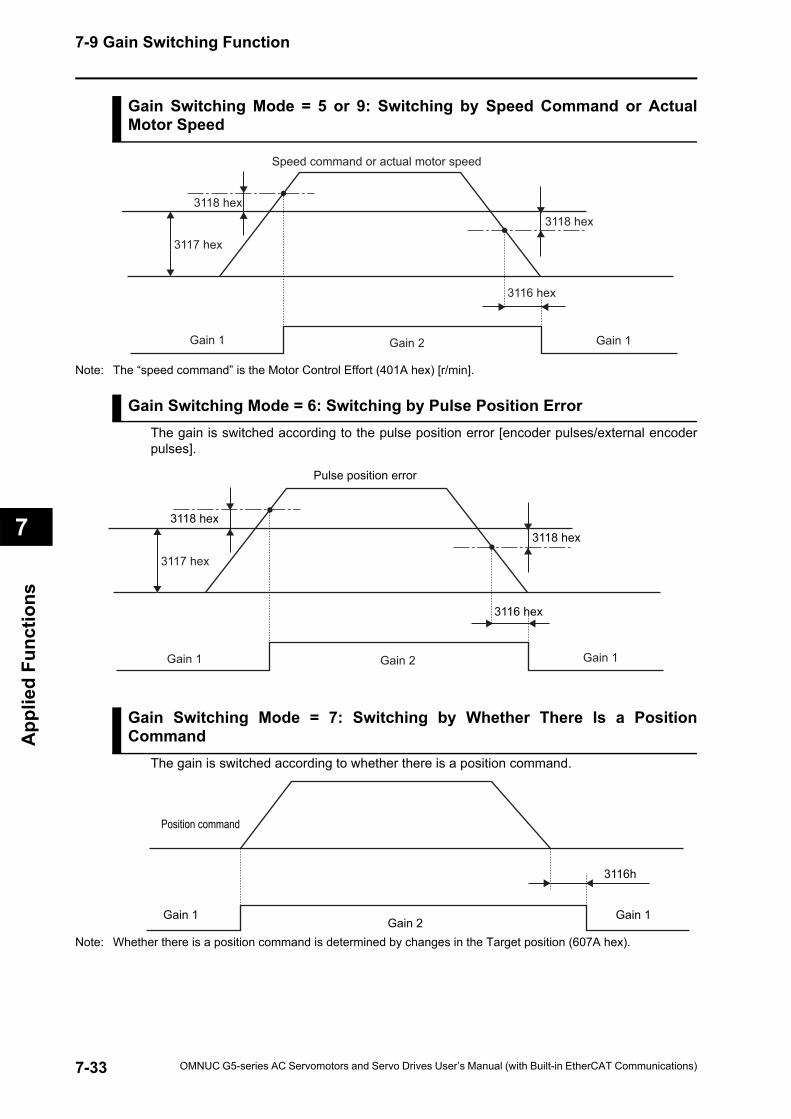
7-9 Gain Switching Function
7
App
lied
Func
tions
Gain Switching Mode = 5 or 9: Switching by Speed Command or ActualMotor Speed
Note: The “speed command” is the Motor Control Effort (401A hex) [r/min].
Gain Switching Mode = 6: Switching by Pulse Position ErrorThe gain is switched according to the pulse position error [encoder pulses/external encoderpulses].
Gain Switching Mode = 7: Switching by Whether There Is a PositionCommand
The gain is switched according to whether there is a position command.
Note: Whether there is a position command is determined by changes in the Target position (607A hex).
3118 hex
3117 hex
3118 hex
3116 hex
Gain 1 Gain 1Gain 2
Speed command or actual motor speed
Pulse position error
3118 hex3118 hex
3116 hex
3117 hex
Gain 1 Gain 1Gain 2
Gain 1 Gain 1Gain 2
3116h
Position command
7-33 OMNUC G5-series AC Servomotors and Servo Drives User’s Manual (with Built-in EtherCAT Communications)
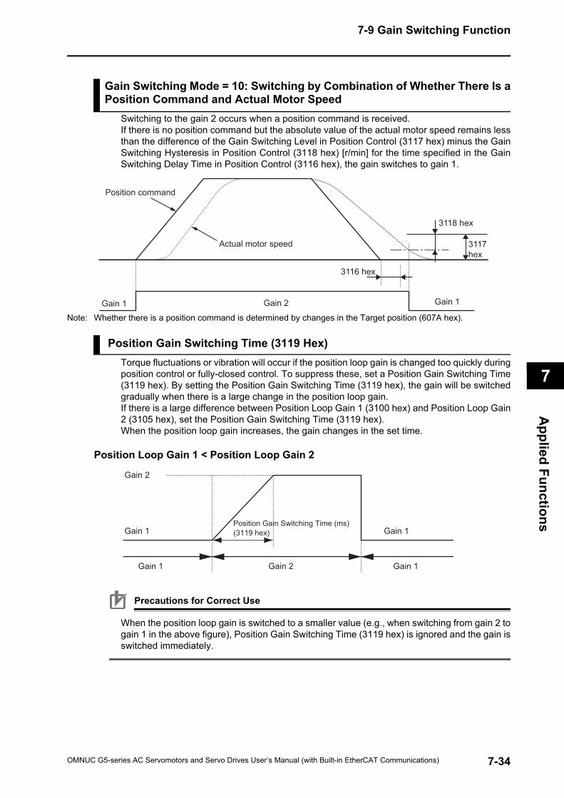
7
7-9 Gain Switching FunctionA
pplied Functions
Gain Switching Mode = 10: Switching by Combination of Whether There Is aPosition Command and Actual Motor Speed
Switching to the gain 2 occurs when a position command is received.If there is no position command but the absolute value of the actual motor speed remains lessthan the difference of the Gain Switching Level in Position Control (3117 hex) minus the GainSwitching Hysteresis in Position Control (3118 hex) [r/min] for the time specified in the GainSwitching Delay Time in Position Control (3116 hex), the gain switches to gain 1.
Note: Whether there is a position command is determined by changes in the Target position (607A hex).
Position Gain Switching Time (3119 Hex)Torque fluctuations or vibration will occur if the position loop gain is changed too quickly duringposition control or fully-closed control. To suppress these, set a Position Gain Switching Time(3119 hex). By setting the Position Gain Switching Time (3119 hex), the gain will be switchedgradually when there is a large change in the position loop gain. If there is a large difference between Position Loop Gain 1 (3100 hex) and Position Loop Gain2 (3105 hex), set the Position Gain Switching Time (3119 hex). When the position loop gain increases, the gain changes in the set time.
Position Loop Gain 1 < Position Loop Gain 2
Precautions for Correct Use
When the position loop gain is switched to a smaller value (e.g., when switching from gain 2 togain 1 in the above figure), Position Gain Switching Time (3119 hex) is ignored and the gain isswitched immediately.
3116 hex
3118 hex
3117 hex
Gain 1 Gain 1Gain 2
Actual motor speed
Position command
Gain 1 Gain 1
Gain 2
Position Gain Switching Time (ms)(3119 hex)
Gain 1 Gain 2 Gain 1
7-34OMNUC G5-series AC Servomotors and Servo Drives User’s Manual (with Built-in EtherCAT Communications)
7-10 Gain Switching 3 Function
7
App
lied
Func
tions
7-10 Gain Switching 3 FunctionThis function adds a new setting (gain 3) to the gain switching function of the Gain SwitchingInput Operating Mode Selection (3114 hex). It switches the gain right before a stop.The positioning time can be reduced by keeping the gain immediately before the stop at ahigher level for a certain period of time.
Operating ConditionsYou can use the gain 3 switching function in the following situations for position control or fully-closed control.
Objects Requiring Settings
Conditions
Operating mode Position Control Mode or Fully-closed Control Mode
Others Servo ON state. The factors other than control parameters must be set correctly. This includes the torque limit. The motor must operate normally without any failures.
Index Name Explanation Reference
3605 hex Gain 3 Effective Time Set effective time of gain 3. page 9-47
3606 hex Gain 3 Ratio Setting Set gain 3 as a multiple of gain 1. page 9-47
7-35 OMNUC G5-series AC Servomotors and Servo Drives User’s Manual (with Built-in EtherCAT Communications)
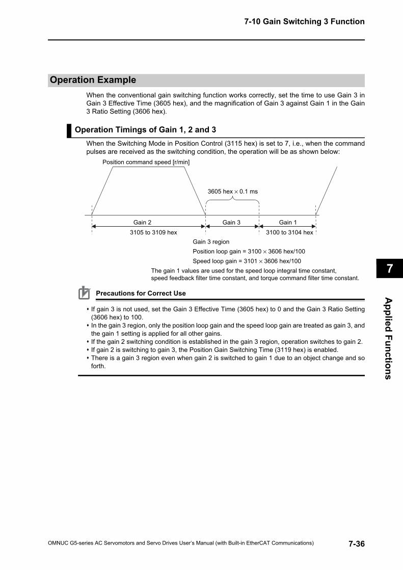
7
7-10 Gain Switching 3 FunctionA
pplied Functions
Operation ExampleWhen the conventional gain switching function works correctly, set the time to use Gain 3 inGain 3 Effective Time (3605 hex), and the magnification of Gain 3 against Gain 1 in the Gain3 Ratio Setting (3606 hex).
Operation Timings of Gain 1, 2 and 3When the Switching Mode in Position Control (3115 hex) is set to 7, i.e., when the commandpulses are received as the switching condition, the operation will be as shown below:
Precautions for Correct Use
If gain 3 is not used, set the Gain 3 Effective Time (3605 hex) to 0 and the Gain 3 Ratio Setting(3606 hex) to 100.In the gain 3 region, only the position loop gain and the speed loop gain are treated as gain 3, andthe gain 1 setting is applied for all other gains.If the gain 2 switching condition is established in the gain 3 region, operation switches to gain 2.If gain 2 is switching to gain 3, the Position Gain Switching Time (3119 hex) is enabled.There is a gain 3 region even when gain 2 is switched to gain 1 due to an object change and soforth.
Gain 2 Gain 3 Gain 1
Position command speed [r/min]
3605 hex × 0.1 ms
3105 to 3109 hexGain 3 regionPosition loop gain = 3100 × 3606 hex/100Speed loop gain = 3101 × 3606 hex/100
The gain 1 values are used for the speed loop integral time constant,speed feedback filter time constant, and torque command filter time constant.
3100 to 3104 hex
7-36OMNUC G5-series AC Servomotors and Servo Drives User’s Manual (with Built-in EtherCAT Communications)
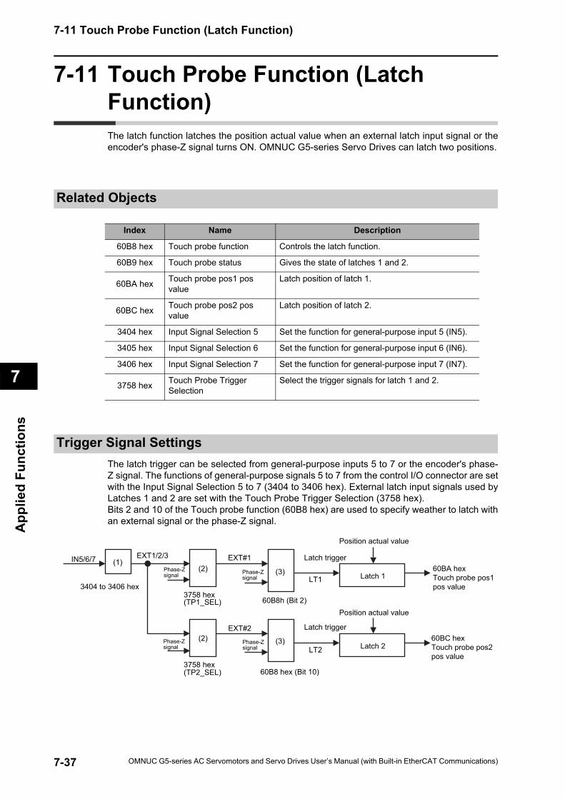
7-11 Touch Probe Function (Latch Function)
7
App
lied
Func
tions
7-11 Touch Probe Function (Latch Function)The latch function latches the position actual value when an external latch input signal or theencoder's phase-Z signal turns ON. OMNUC G5-series Servo Drives can latch two positions.
Related Objects
Trigger Signal SettingsThe latch trigger can be selected from general-purpose inputs 5 to 7 or the encoder's phase-Z signal. The functions of general-purpose signals 5 to 7 from the control I/O connector are setwith the Input Signal Selection 5 to 7 (3404 to 3406 hex). External latch input signals used byLatches 1 and 2 are set with the Touch Probe Trigger Selection (3758 hex).Bits 2 and 10 of the Touch probe function (60B8 hex) are used to specify weather to latch withan external signal or the phase-Z signal.
Index Name Description
60B8 hex Touch probe function Controls the latch function.
60B9 hex Touch probe status Gives the state of latches 1 and 2.
60BA hex Touch probe pos1 pos value
Latch position of latch 1.
60BC hex Touch probe pos2 pos value
Latch position of latch 2.
3404 hex Input Signal Selection 5 Set the function for general-purpose input 5 (IN5).
3405 hex Input Signal Selection 6 Set the function for general-purpose input 6 (IN6).
3406 hex Input Signal Selection 7 Set the function for general-purpose input 7 (IN7).
3758 hex Touch Probe Trigger Selection
Select the trigger signals for latch 1 and 2.
IN5/6/7 (1)EXT1/2/3 EXT#1
3758 hex(TP1_SEL)
3404 to 3406 hex
(3)(2)Latch trigger
LT1
3758 hex(TP2_SEL) 60B8 hex (Bit 10)
60B8h (Bit 2)
(2) (3)
EXT#2 Latch trigger
LT2
Latch 1
Latch 2
Position actual value
Position actual value
60BA hexTouch probe pos1pos value
60BC hexTouch probe pos2pos value
Phase-Z signal Phase-Z
signal
Phase-Z signal
Phase-Z signal
7-37 OMNUC G5-series AC Servomotors and Servo Drives User’s Manual (with Built-in EtherCAT Communications)
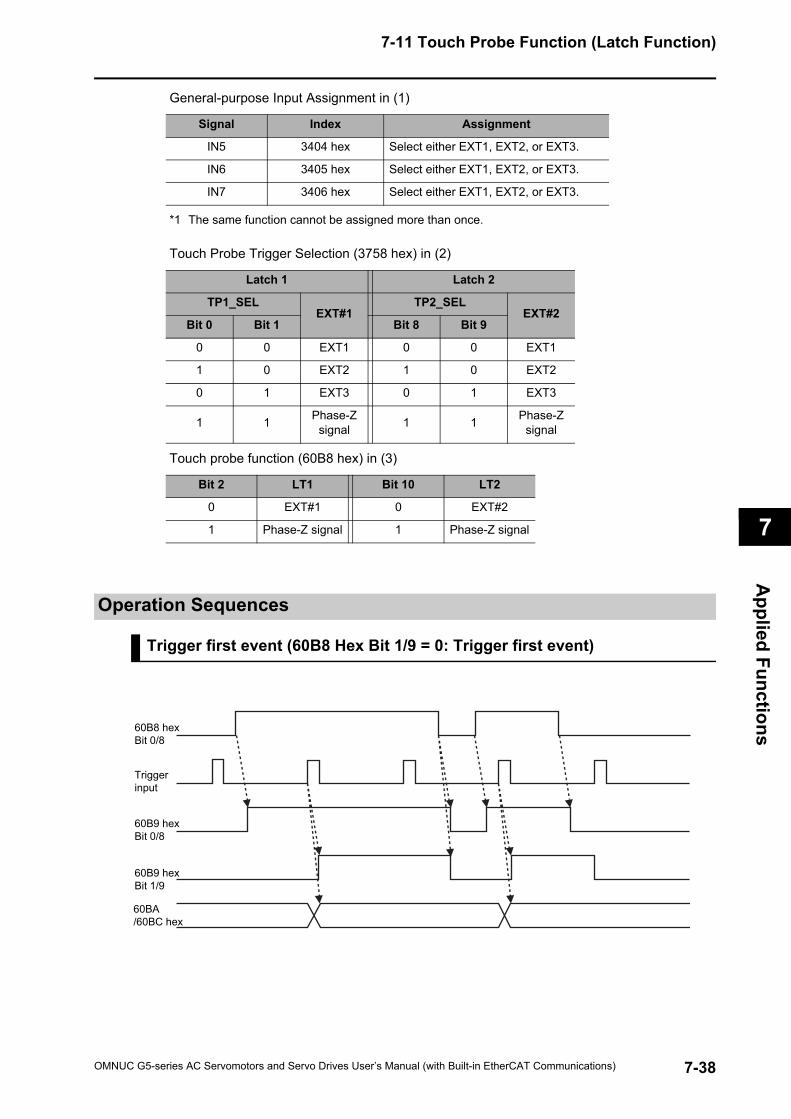
7
7-11 Touch Probe Function (Latch Function)A
pplied Functions
General-purpose Input Assignment in (1)
*1 The same function cannot be assigned more than once.
Touch Probe Trigger Selection (3758 hex) in (2)
Touch probe function (60B8 hex) in (3)
Operation Sequences
Trigger first event (60B8 Hex Bit 1/9 = 0: Trigger first event)
Signal Index Assignment
IN5 3404 hex Select either EXT1, EXT2, or EXT3.
IN6 3405 hex Select either EXT1, EXT2, or EXT3.
IN7 3406 hex Select either EXT1, EXT2, or EXT3.
Latch 1 Latch 2
TP1_SELEXT#1
TP2_SELEXT#2
Bit 0 Bit 1 Bit 8 Bit 9
0 0 EXT1 0 0 EXT1
1 0 EXT2 1 0 EXT2
0 1 EXT3 0 1 EXT3
1 1 Phase-Z signal 1 1 Phase-Z
signal
Bit 2 LT1 Bit 10 LT2
0 EXT#1 0 EXT#2
1 Phase-Z signal 1 Phase-Z signal
60B8 hex Bit 0/8
60B9 hexBit 0/8
60B9 hexBit 1/9
Trigger input
60BA/60BC hex
7-38OMNUC G5-series AC Servomotors and Servo Drives User’s Manual (with Built-in EtherCAT Communications)
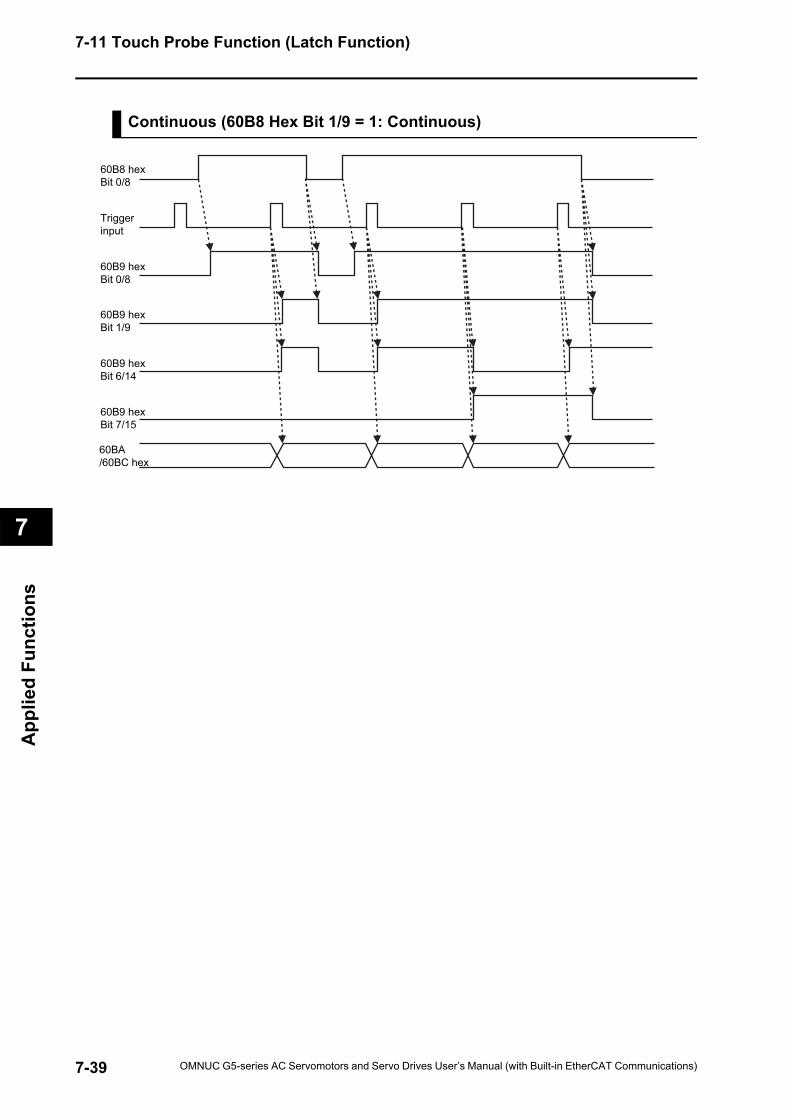
7-11 Touch Probe Function (Latch Function)
7
App
lied
Func
tions
Continuous (60B8 Hex Bit 1/9 = 1: Continuous)
60B8 hexBit 0/8
60B9 hexBit 0/8
60B9 hexBit 1/9
Trigger input
60BA/60BC hex
60B9 hexBit 6/14
60B9 hexBit 7/15
7-39 OMNUC G5-series AC Servomotors and Servo Drives User’s Manual (with Built-in EtherCAT Communications)
8
Safety FunctionThis function stops the Servomotor based on a signal from a safety controller orsafety sensor. An outline of the function is given together with operation andconnection examples.
8-1 Safe Torque OFF Function...........................................8-18-2 Operation Example .......................................................8-48-3 Connection Examples ..................................................8-6
OMNUC G5-series AC Servomotors and Servo Drives User’s Manual (with Built-in EtherCAT Communications)
8-1 Safe Torque OFF Function
8
Safe
ty F
unct
ion
8-1 Safe Torque OFF FunctionThe safe torque OFF function (hereinafter referred to as STO according to IEC 61800-5-2) isused to cut off the motor current and stop the motor through the input signals from a safetydevice, such as a safety controller or safety sensor, that is connected to the safety connector(CN8).When the STO function is operating, the Servo Drive turns OFF the servo ready completedoutput (READY) to go into the safety status.
The PFH value is 2.30 × 10⁻⁸.
Precautions for Safe Use
When using the STO function, be sure to execute a risk assessment of the equipment to confirmthat the system safety requirements are met.There are the following risks even when the STO function is operating. Be sure to take safety intoaccount as part of the risk assessment.
• The motor runs if an external force is present (e.g., force of gravity on a vertical axis). If holding is required, implement appropriate measures, such as providing external brakes. The brakes for a Servo Drive with brakes are used for holding only, and cannot be used for control.
• Even if there is no external force, when the Fault reaction option code (605E hex) is set to free-run with the dynamic brake disabled, the motor uses free-run stopping and the stop distance is long.
• In case of internal failure of components, the motor may operate in the range of up to 180 degrees of electrical angle.
• The power supply to the motor is cut off by the STO function, but the power supply to the Servo Drive will not be cut off nor electrically isolated. For Servo Drive maintenance, cut off the power supply to the Servo Drive through another means.
Do not use the EDM output for any purpose other than the failure monitoring function. The EDMoutput signal is not a safety output.The dynamic brake and external brake release signal outputs are not safety-related parts. Makesure to design the equipment not to be dangerous even if the external brake release fails duringthe STO status.When using the STO function, connect equipment that meets the safety standards.The OMNUC G5-series AC Servo Drives fulfill the requirements of the following certifications(application pending):
• CAT-3 (EN 954-1, EN/ISO 13849-1)• Performance level d (EN/ISO 13849-1)• SIL 2 (IEC/EN 62061)
8-1 OMNUC G5-series AC Servomotors and Servo Drives User’s Manual (with Built-in EtherCAT Communications)
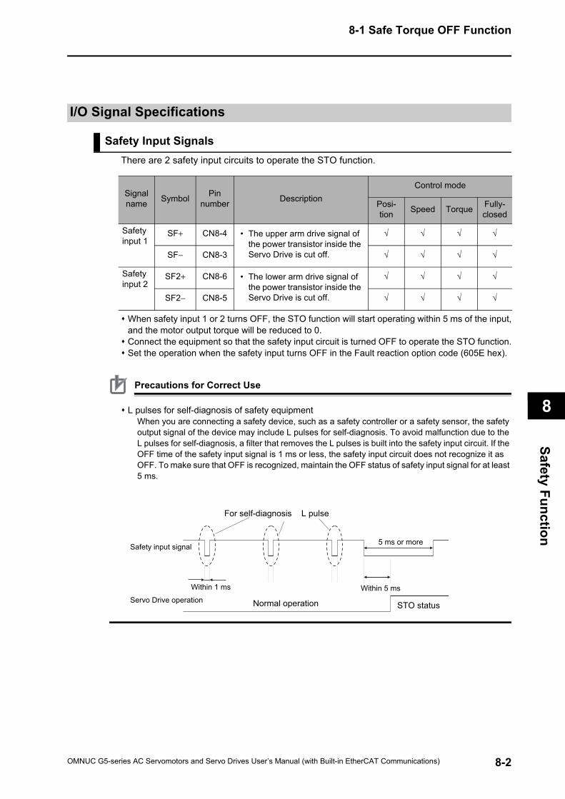
8-1 Safe Torque OFF Function
8
Safety Function
I/O Signal Specifications
Safety Input SignalsThere are 2 safety input circuits to operate the STO function.
When safety input 1 or 2 turns OFF, the STO function will start operating within 5 ms of the input,and the motor output torque will be reduced to 0.Connect the equipment so that the safety input circuit is turned OFF to operate the STO function.Set the operation when the safety input turns OFF in the Fault reaction option code (605E hex).
Precautions for Correct Use
L pulses for self-diagnosis of safety equipmentWhen you are connecting a safety device, such as a safety controller or a safety sensor, the safety output signal of the device may include L pulses for self-diagnosis. To avoid malfunction due to the L pulses for self-diagnosis, a filter that removes the L pulses is built into the safety input circuit. If the OFF time of the safety input signal is 1 ms or less, the safety input circuit does not recognize it as OFF. To make sure that OFF is recognized, maintain the OFF status of safety input signal for at least 5 ms.
Signal name Symbol Pin
number DescriptionControl mode
Posi-tion Speed Torque Fully-
closed
Safety input 1
SF+ CN8-4 • The upper arm drive signal of the power transistor inside the Servo Drive is cut off.
√ √ √ √
SF− CN8-3 √ √ √ √
Safety input 2
SF2+ CN8-6 • The lower arm drive signal of the power transistor inside the Servo Drive is cut off.
√ √ √ √
SF2− CN8-5 √ √ √ √
For self-diagnosis L pulse
Within 1 ms Within 5 ms
Normal operation STO status
Safety input signal
Servo Drive operation
5 ms or more
8-2OMNUC G5-series AC Servomotors and Servo Drives User’s Manual (with Built-in EtherCAT Communications)
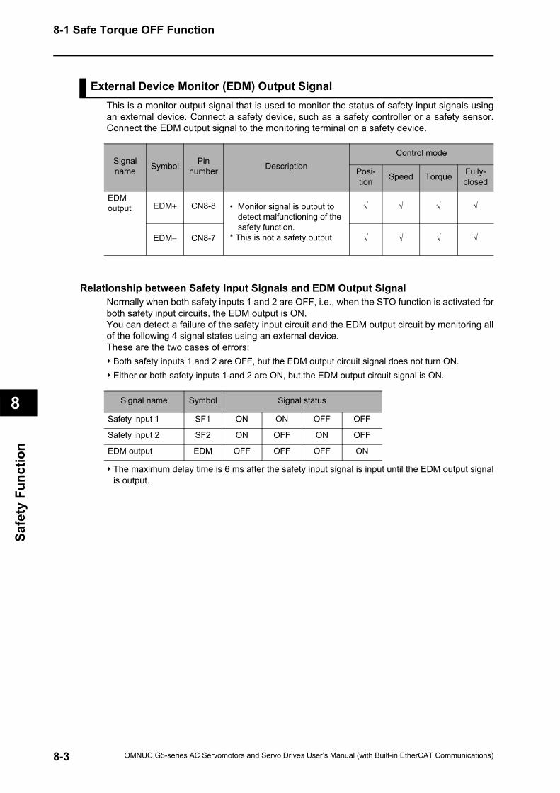
8-1 Safe Torque OFF Function
8
Safe
ty F
unct
ion
External Device Monitor (EDM) Output SignalThis is a monitor output signal that is used to monitor the status of safety input signals usingan external device. Connect a safety device, such as a safety controller or a safety sensor.Connect the EDM output signal to the monitoring terminal on a safety device.
Relationship between Safety Input Signals and EDM Output SignalNormally when both safety inputs 1 and 2 are OFF, i.e., when the STO function is activated forboth safety input circuits, the EDM output is ON.You can detect a failure of the safety input circuit and the EDM output circuit by monitoring allof the following 4 signal states using an external device.These are the two cases of errors:
Both safety inputs 1 and 2 are OFF, but the EDM output circuit signal does not turn ON.Either or both safety inputs 1 and 2 are ON, but the EDM output circuit signal is ON.
The maximum delay time is 6 ms after the safety input signal is input until the EDM output signalis output.
Signal name Symbol Pin
number DescriptionControl mode
Posi-tion Speed Torque Fully-
closed
EDM output EDM+ CN8-8 • Monitor signal is output to
detect malfunctioning of the safety function.
* This is not a safety output.
√ √ √ √
EDM− CN8-7 √ √ √ √
Signal name Symbol Signal status
Safety input 1 SF1 ON ON OFF OFF
Safety input 2 SF2 ON OFF ON OFF
EDM output EDM OFF OFF OFF ON
8-3 OMNUC G5-series AC Servomotors and Servo Drives User’s Manual (with Built-in EtherCAT Communications)
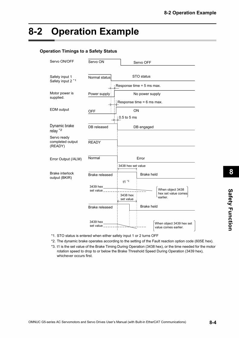
8-2 Operation Example
8
Safety Function
8-2 Operation Example
Operation Timings to a Safety Status
*1. STO status is entered when either safety input 1 or 2 turns OFF*2. The dynamic brake operates according to the setting of the Fault reaction option code (605E hex). *3. t1 is the set value of the Brake Timing During Operation (3438 hex), or the time needed for the motor
rotation speed to drop to or below the Brake Threshold Speed During Operation (3439 hex), whichever occurs first.
Normal status
DB engaged
Brake released
DB released
3439 hexset value
3438 hexset value
3439 hexset value
When object 3438 hex set value comes earlier.
When object 3439 hex set value comes earlier.
READY
Normal
3438 hex set value
t1 *3
Error
Brake held
Brake released Brake held
STO statusSafety input 1Safety input 2 *1
No power supplyPower supply
Response time = 5 ms max.
Motor power is supplied.
Dynamic brake relay *2
Brake interlock output (BKIR)
Servo ready completed output (READY)
Error Output (/ALM)
Servo ON/OFF Servo ON Servo OFF
ONOFF
Response time = 6 ms max.
EDM output
0.5 to 5 ms
8-4OMNUC G5-series AC Servomotors and Servo Drives User’s Manual (with Built-in EtherCAT Communications)
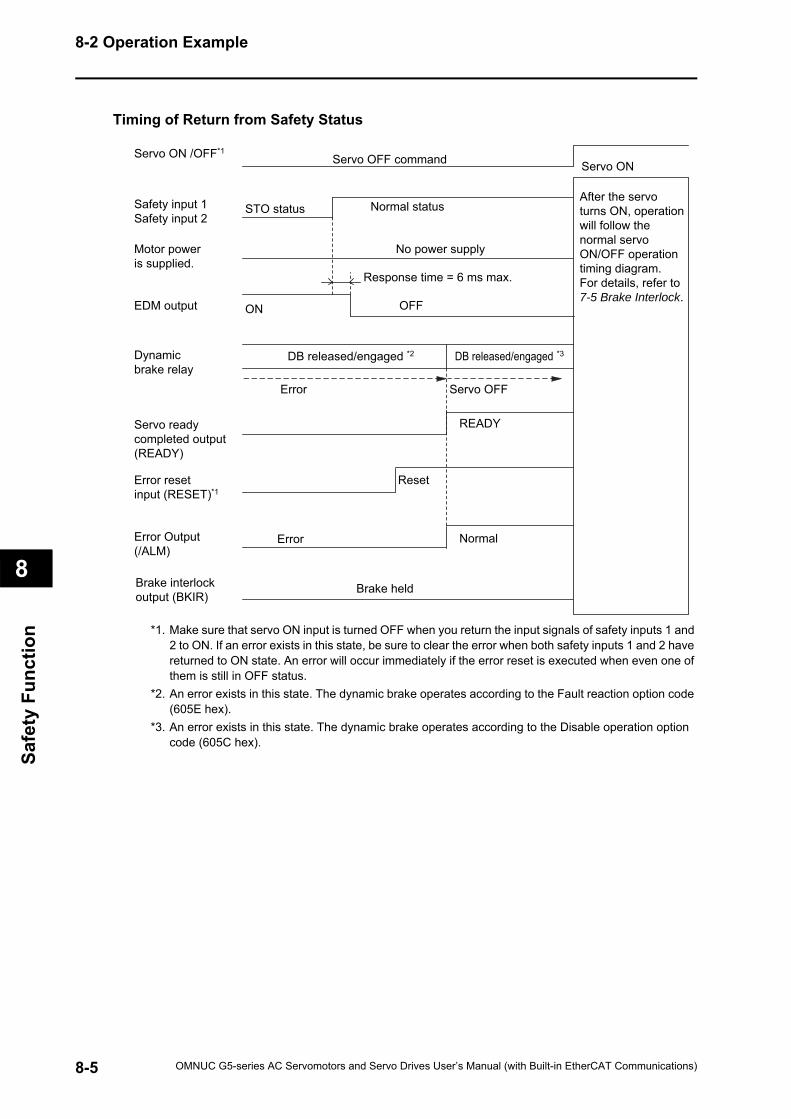
8-2 Operation Example
8
Safe
ty F
unct
ion
Timing of Return from Safety Status
*1. Make sure that servo ON input is turned OFF when you return the input signals of safety inputs 1 and 2 to ON. If an error exists in this state, be sure to clear the error when both safety inputs 1 and 2 have returned to ON state. An error will occur immediately if the error reset is executed when even one of them is still in OFF status.
*2. An error exists in this state. The dynamic brake operates according to the Fault reaction option code (605E hex).
*3. An error exists in this state. The dynamic brake operates according to the Disable operation option code (605C hex).
STO status Normal status
Servo ONServo OFF command
No power supply
Response time = 6 ms max.
READY
Error
Brake held
Reset
Normal
DB released/engaged *2
Servo OFF
DB released/engaged *3
Error
Safety input 1Safety input 2
Servo ON /OFF*1
Brake interlockoutput (BKIR)
Motor poweris supplied.
Servo ready completed output (READY)
Error Output (/ALM)
Error resetinput (RESET)*1
Dynamicbrake relay
EDM output ON OFF
After the servo turns ON, operation will follow the normal servo ON/OFF operation timing diagram. For details, refer to 7-5 Brake Interlock.
8-5 OMNUC G5-series AC Servomotors and Servo Drives User’s Manual (with Built-in EtherCAT Communications)
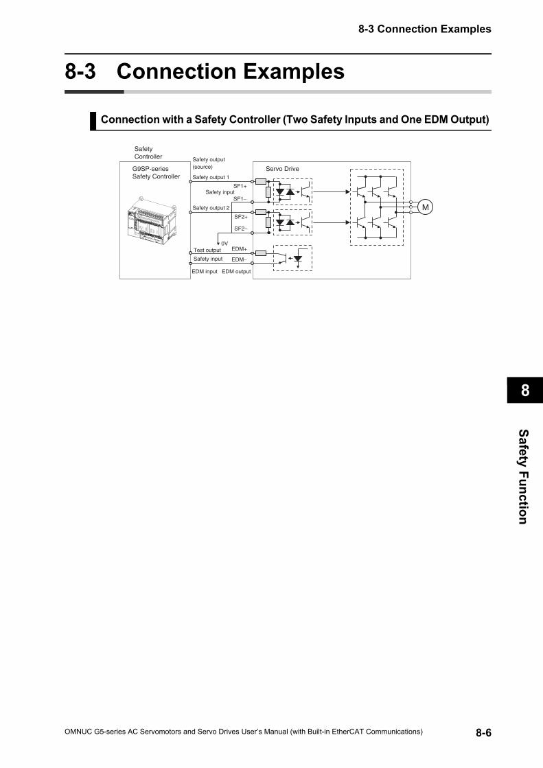
8-3 Connection Examples
8
Safety Function
8-3 Connection Examples
Connection with a Safety Controller (Two Safety Inputs and One EDM Output)
EDM output
SF1+
SF2+
SF2−
EDM+
EDM−
MSF1−
Safety Controller
Servo Drive
Safety input
0VTest output
Safety input
EDM input
G9SP-series Safety Controller
Safety output (source)
Safety output 1
Safety output 2
8-6OMNUC G5-series AC Servomotors and Servo Drives User’s Manual (with Built-in EtherCAT Communications)

9
Details on Servo Parameter ObjectsThis chapter explains the settings of each object.
9-1 Basic Settings ...............................................................9-19-2 Gain Settings.................................................................9-79-3 Vibration Suppression Settings ................................9-209-4 Analog Control Objects..............................................9-269-5 Interface Monitor Settings .........................................9-319-6 Extended Objects .......................................................9-409-7 Special Objects ...........................................................9-47
OMNUC G5-series AC Servomotors and Servo Drives User’s Manual (with Built-in EtherCAT Communications)
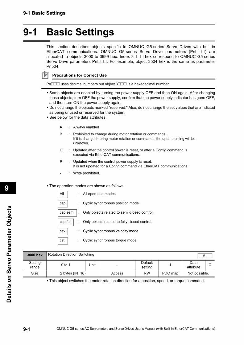
9-1 Basic Settings
9
Det
ails
on
Serv
o Pa
ram
eter
Obj
ects
9-1 Basic SettingsThis section describes objects specific to OMNUC G5-series Servo Drives with built-inEtherCAT communications. OMNUC G5-series Servo Drive parameters (Pn@@@) areallocated to objects 3000 to 3999 hex. Index 3@@@ hex correspond to OMNUC G5-seriesServo Drive parameters Pn@@@. For example, object 3504 hex is the same as parameterPn504.
Precautions for Correct Use
Pn@@@ uses decimal numbers but object 3@@@ is a hexadecimal number.
Some objects are enabled by turning the power supply OFF and then ON again. After changingthese objects, turn OFF the power supply, confirm that the power supply indicator has gone OFF,and then turn ON the power supply again.Do not change the objects marked "reserved." Also, do not change the set values that are indictedas being unused or reserved for the system.See below for the data attributes.
The operation modes are shown as follows:
This object switches the motor rotation direction for a position, speed, or torque command.
A : Always enabled
B : Prohibited to change during motor rotation or commands.If it is changed during motor rotation or commands, the update timing will be unknown.
C : Updated after the control power is reset, or after a Config command is executed via EtherCAT communications.
R : Updated when the control power supply is reset.It is not updated for a Config command via EtherCAT communications.
- : Write prohibited.
All : All operation modes
csp : Cyclic synchronous position mode
csp semi : Only objects related to semi-closed control.
csp full : Only objects related to fully-closed control.
csv : Cyclic synchronous velocity mode
cst : Cyclic synchronous torque mode
3000 hex Rotation Direction Switching
Setting range 0 to 1 Unit − Default
setting 1 Data attribute C
Size 2 bytes (INT16) Access RW PDO map Not possible.
All
9-1 OMNUC G5-series AC Servomotors and Servo Drives User’s Manual (with Built-in EtherCAT Communications)
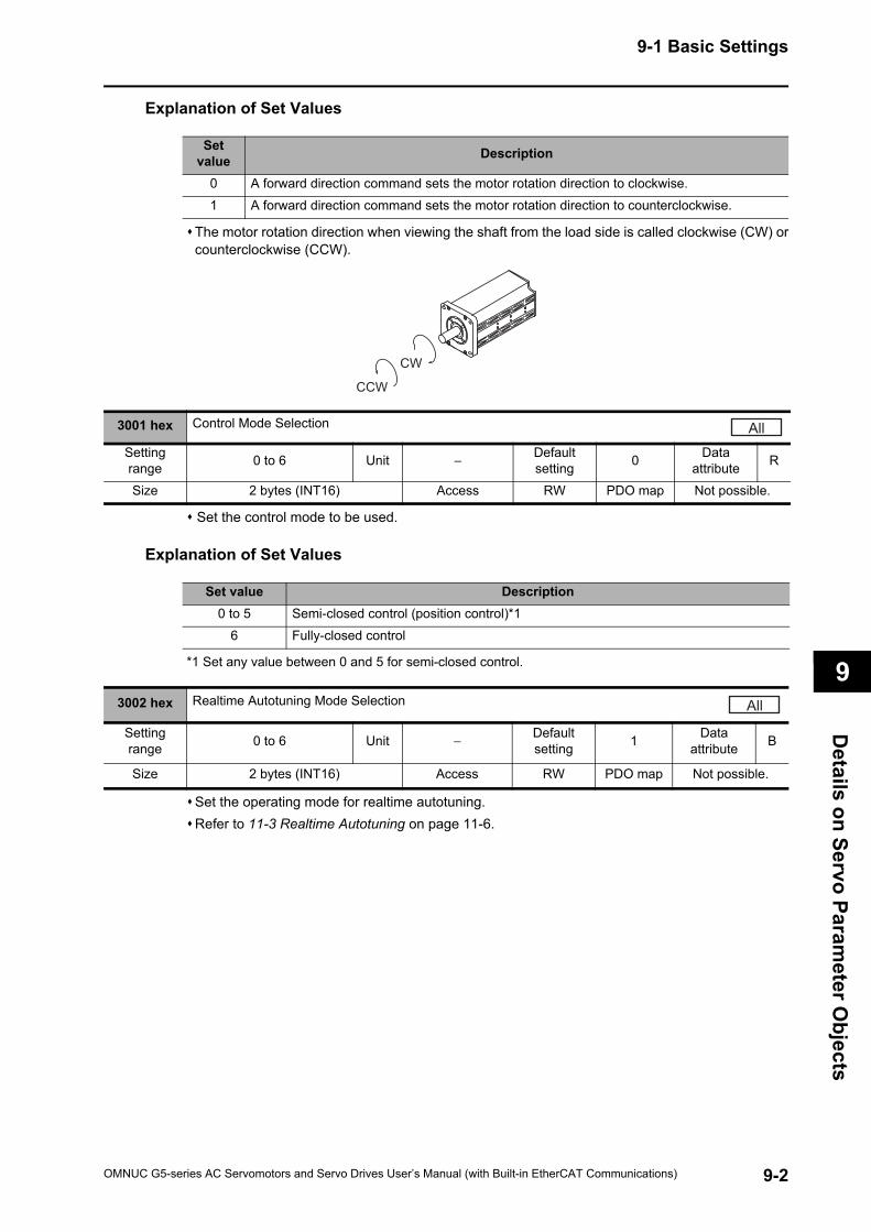
9-1 Basic Settings
9
Details on Servo Param
eter Objects
Explanation of Set Values
The motor rotation direction when viewing the shaft from the load side is called clockwise (CW) orcounterclockwise (CCW).
Set the control mode to be used.
Explanation of Set Values
*1 Set any value between 0 and 5 for semi-closed control.
Set the operating mode for realtime autotuning.Refer to 11-3 Realtime Autotuning on page 11-6.
Set value Description
0 A forward direction command sets the motor rotation direction to clockwise.
1 A forward direction command sets the motor rotation direction to counterclockwise.
CW
CCW
3001 hex Control Mode Selection
Setting range 0 to 6 Unit − Default
setting 0 Data attribute R
Size 2 bytes (INT16) Access RW PDO map Not possible.
All
Set value Description0 to 5 Semi-closed control (position control)*1
6 Fully-closed control
3002 hex Realtime Autotuning Mode Selection
Setting range 0 to 6 Unit − Default
setting 1 Data attribute B
Size 2 bytes (INT16) Access RW PDO map Not possible.
All
9-2OMNUC G5-series AC Servomotors and Servo Drives User’s Manual (with Built-in EtherCAT Communications)
9-1 Basic Settings
9
Det
ails
on
Serv
o Pa
ram
eter
Obj
ects
Explanation of Set Values
*1. The default setting is 11 for a Drive with 200 V and 1 kW or greater, or for a Drive with 400 V. Set the machine rigidity to one of 32 levels when realtime autotuning is enabled.The higher the machine rigidity set value is, the higher the responsiveness is, however, the morevibration occurs.
Refer to 11-3 Realtime Autotuning on page 11-6.
Precautions for Correct Use
If the set value is changed suddenly by a large amount, the gain may change rapidly, subjectingthe machine to shock. Always start with a small setting, and gradually increase the setting whilemonitoring machine operation.
Set the load inertia as a percentage of the motor rotor inertia. 3004 hex = (Load inertia/Rotor inertia) × 100% When realtime autotuning is enabled, the inertia ratio is continuously estimated and saved inEEPROM every 30 minutes. If the inertia ratio is set correctly, the setting unit for the Speed Loop Gain 1 (3101 hex) and SpeedLoop Gain 2 (3106 hex) is Hz.If the Inertia Ratio (3004 hex) is set larger than the actual value, the setting for speed loop gain will
Set value Realtime autotuning Description
0 Disabled Realtime autotuning is disabled.
1 Focus on stability (default setting)
No unbalanced load, friction compensation, or gain switching.
2 Focus on position control
Used for a horizontal axis or other axes that have no unbalanced load, or for a ball screw drive with little friction.
3 Vertical axis Used when an unbalanced load is present, such as a vertical axis.
4Friction compensation and vertical axis
Used when friction is large (unbalanced load also calculated).Used for a belt-driving shaft with large friction. Variations in finalizing the positioning are suppressed.
5 Load characteristic estimation
Used only for estimating load characteristics.
6Customization This mode is used for customizing the realtime autotuning function
by using the Realtime Autotuning Customization Mode Setting (3632 hex).
3003 hex Realtime Autotuning Machine Rigidity Setting
Setting range 0 to 31 Unit − Default
setting 13 *1 Data attribute B
Size 2 bytes (INT16) Access RW PDO map Not possible.
All
3004 hex Inertia Ratio
Setting range 0 to 10000 Unit % Default
setting 250 Data attribute B
Size 2 bytes (INT16) Access RW PDO map Not possible.
LowLow
Low
←Machine rigidity→←Servo gain→
←Responsiveness→
HighHigh
High
0.1 - - - - - - - - - - - - - - - 31 3003h
All
9-3 OMNUC G5-series AC Servomotors and Servo Drives User’s Manual (with Built-in EtherCAT Communications)

9-1 Basic Settings
9
Details on Servo Param
eter Objects
increase. If the Inertia Ratio (3004 hex) is set smaller than the actual value, the setting for speedloop gain will decrease.
*1. It is limited by the maximum torque of the connected motor. Set the limit values for the motor output torques (3013 hex: External Torque Limit 1, 3522 hex:External Torque Limit 2). Refer to the Torque Limit Selection (3521 hex) for the torque limit selection. During torque control, it limits the maximum torque in forward and reverse directions. The settingson the Torque Limit Selection (3521 hex) and the External Torque Limit 2 (3522 hex) are ignored. Set a value in percentage against the rated torque.E.g. When the maximum torque is limited to 150%.
Refer to 7-7 Torque Limit Switching on page 7-21 for the torque control and the torque limitselection.
Set the operating method for the 17-bit absolute encoder.
Explanation of Set Values
3013 hex External Torque Limit 1
Setting range 0 to 5000 Unit % Default
setting 5000*1 Data attribute B
Size 2 bytes (INT16) Access RW PDO map Not possible.
3015 hex Operation Switch when Using Absolute Encoder
Setting range 0 to 2 Unit − Default
setting 2 Data attribute C
Size 2 bytes (INT16) Access RW PDO map Not possible.
All
Speed
200
100 (rating)
(rating)100
200
300
Torque [%]300 (max)
(max)
Reversed direction
Forward direction
If 3013 and 3522 hex = 150.
csp
Set value Description
0 Use as absolute encoder.
1 Use as incremental encoder.
2 Use as absolute encoder but ignore multi-rotation counter overflow.
9-4OMNUC G5-series AC Servomotors and Servo Drives User’s Manual (with Built-in EtherCAT Communications)
9-1 Basic Settings
9
Det
ails
on
Serv
o Pa
ram
eter
Obj
ects
*1. The default setting is 0 for a Drive with 100 V and 400 W, with 200 V and 750 W or greater, or with 400 V.The setting is different whether the Regeneration Resistor built in the Drive is directly used, or it isremoved and replaced by an External Regeneration Resistor. In the latter case, the resistor isconnected to the External Regeneration Resistor connection terminal.
Explanation of Set Values
Precautions for Correct Use
Do not touch the External Regeneration Resistor. A burn injury may result.Always provide a temperature fuse or other protective measure when using an ExternalRegeneration Resistor. Regardless of whether the regeneration overload error is enabled ordisabled, the Regeneration Resistor can generate heat and may cause burning.To use the Built-in Regeneration Resistor, always set this object to 0.
Select the method to calculate the regeneration resistance load ratio, when the External Resistoris selected in the Regeneration Resistor Selection (3016 hex = 1 or 2).
3016 hex Regeneration Resistor Selection
Setting range 0 to 3 Unit − Default
setting 3*1 Data attribute C
Size 2 bytes (INT16) Access RW PDO map Not possible.
All
Set value Description
0Regeneration Resistor used: Built-in ResistorThe regeneration processing circuit operates and the Regeneration Overload Error (Error No. 18) are enabled according to the Built-in Resistor (with approx. 1% duty).
1Regeneration Resistor used: External ResistorThe regeneration processing circuit operates, and Regeneration Overload Error (Error No. 18) cause a trip when the operating rate of the Regeneration Resistor exceeds 10%.
2Regeneration Resistor used: External ResistorThe regeneration processing circuit operates, but Regeneration Overload Error (Error No. 18) do not occur.
3Regeneration Resistor used: NoneThe regeneration processing circuit and Regeneration Overload Error (Error No. 18) do not operate, and all regenerative energy is processed by the built-in capacitor.
3017 hex External Regeneration Resistor Setting
Setting range 0 to 4 Unit − Default
setting 0 Data attribute C
Size 2 bytes (INT16) Access RW PDO map Not possible.
All
9-5 OMNUC G5-series AC Servomotors and Servo Drives User’s Manual (with Built-in EtherCAT Communications)
9-1 Basic Settings
9
Details on Servo Param
eter Objects
Explanation of Set Values
Set value Description
0 Regeneration load ratio is 100% when operating rate of the External Regeneration Resistor is 10%.
1 Reserved
2 Reserved
3 Reserved
4 Reserved
9-6OMNUC G5-series AC Servomotors and Servo Drives User’s Manual (with Built-in EtherCAT Communications)
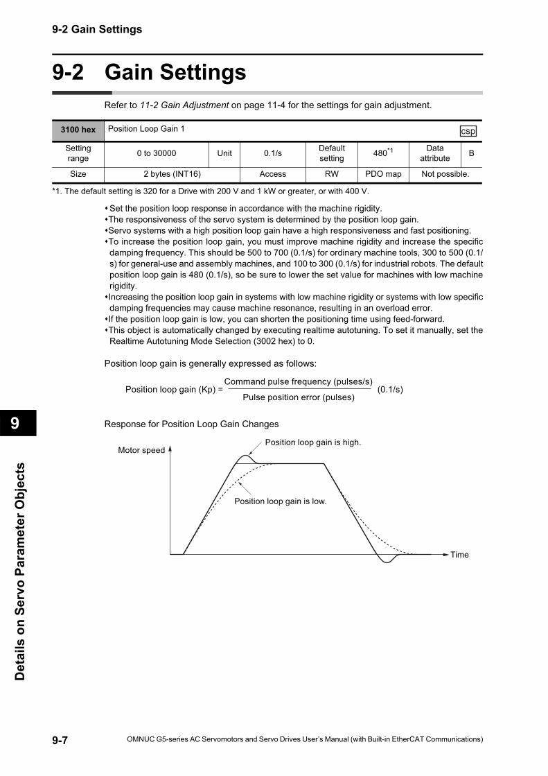
9-2 Gain Settings
9
Det
ails
on
Serv
o Pa
ram
eter
Obj
ects
9-2 Gain SettingsRefer to 11-2 Gain Adjustment on page 11-4 for the settings for gain adjustment.
Set the position loop response in accordance with the machine rigidity.The responsiveness of the servo system is determined by the position loop gain. Servo systems with a high position loop gain have a high responsiveness and fast positioning. To increase the position loop gain, you must improve machine rigidity and increase the specificdamping frequency. This should be 500 to 700 (0.1/s) for ordinary machine tools, 300 to 500 (0.1/s) for general-use and assembly machines, and 100 to 300 (0.1/s) for industrial robots. The defaultposition loop gain is 480 (0.1/s), so be sure to lower the set value for machines with low machinerigidity.Increasing the position loop gain in systems with low machine rigidity or systems with low specificdamping frequencies may cause machine resonance, resulting in an overload error.If the position loop gain is low, you can shorten the positioning time using feed-forward.This object is automatically changed by executing realtime autotuning. To set it manually, set theRealtime Autotuning Mode Selection (3002 hex) to 0.
Position loop gain is generally expressed as follows:
Response for Position Loop Gain Changes
3100 hex Position Loop Gain 1
Setting range 0 to 30000 Unit 0.1/s Default
setting 480*1
*1. The default setting is 320 for a Drive with 200 V and 1 kW or greater, or with 400 V.
Data attribute B
Size 2 bytes (INT16) Access RW PDO map Not possible.
csp
Position loop gain (Kp) =Command pulse frequency (pulses/s)
Pulse position error (pulses)(0.1/s)
Motor speed
Time
Position loop gain is high.
Position loop gain is low.
9-7 OMNUC G5-series AC Servomotors and Servo Drives User’s Manual (with Built-in EtherCAT Communications)
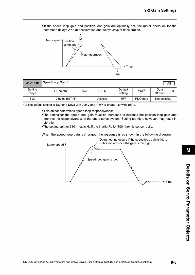
9-2 Gain Settings
9
Details on Servo Param
eter Objects
If the speed loop gain and position loop gain are optimally set, the motor operation for thecommand delays 2/Kp at acceleration and delays 3/Kp at deceleration.
This object determines speed loop responsiveness.The setting for the speed loop gain must be increased to increase the position loop gain andimprove the responsiveness of the entire servo system. Setting too high, however, may result invibration.The setting unit for 3101 hex is Hz if the Inertia Ratio (3004 hex) is set correctly.
When the speed loop gain is changed, the response is as shown in the following diagram.
Kp3
Kp2
Motor speed
Time
Positioncommand
Motor operation
3101 hex Speed Loop Gain 1
Setting range 1 to 32767 Unit 0.1 Hz Default
setting 270*1 Data attribute B
Size 2 bytes (INT16) Access RW PDO map Not possible.
*1. The default setting is 180 for a Drive with 200 V and 1 kW or greater, or with 400 V.
All
Motor speed
Time
Overshooting occurs if the speed loop gain is high.(Vibration occurs if the gain is too high.)
Speed loop gain is low.
9-8OMNUC G5-series AC Servomotors and Servo Drives User’s Manual (with Built-in EtherCAT Communications)
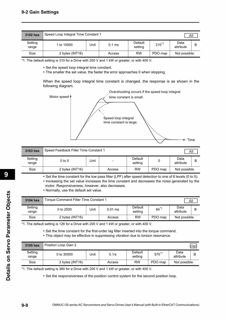
9-2 Gain Settings
9
Det
ails
on
Serv
o Pa
ram
eter
Obj
ects
Set the speed loop integral time constant. The smaller the set value, the faster the error approaches 0 when stopping.
When the speed loop integral time constant is changed, the response is as shown in thefollowing diagram.
Set the time constant for the low pass filter (LPF) after speed detection to one of 6 levels (0 to 5). Increasing the set value increases the time constant and decreases the noise generated by themotor. Responsiveness, however, also decreases. Normally, use the default set value.
Set the time constant for the first-order lag filter inserted into the torque command. This object may be effective in suppressing vibration due to torsion resonance.
Set the responsiveness of the position control system for the second position loop.
3102 hex Speed Loop Integral Time Constant 1
Setting range 1 to 10000 Unit 0.1 ms Default
setting 210*1 Data attribute B
Size 2 bytes (INT16) Access RW PDO map Not possible.
*1. The default setting is 310 for a Drive with 200 V and 1 kW or greater, or with 400 V.
All
Motor speed
Time
Overshooting occurs if the speed loop integraltime constant is small.
Speed loop integraltime constant is large.
3103 hex Speed Feedback Filter Time Constant 1
Setting range 0 to 5 Unit − Default
setting 0 Data attribute B
Size 2 bytes (INT16) Access RW PDO map Not possible.
All
3104 hex Torque Command Filter Time Constant 1
Setting range 0 to 2500 Unit 0.01 ms Default
setting 84*1 Data attribute B
Size 2 bytes (INT16) Access RW PDO map Not possible.
*1. The default setting is 126 for a Drive with 200 V and 1 kW or greater, or with 400 V.
All
3105 hex Position Loop Gain 2
Setting range 0 to 30000 Unit 0.1/s Default
setting 570*1
*1. The default setting is 380 for a Drive with 200 V and 1 kW or greater, or with 400 V.
Data attribute B
Size 2 bytes (INT16) Access RW PDO map Not possible.
csp
9-9 OMNUC G5-series AC Servomotors and Servo Drives User’s Manual (with Built-in EtherCAT Communications)
9-2 Gain Settings
9
Details on Servo Param
eter Objects
Set the responsiveness of the second speed loop.
Set the second speed loop integral time constant.
Set the second speed feedback filter.
Set the second torque filter time constant.The objects from 3105 to 3109 hex are the gain and time constants to be selected when the GainSwitching Input Operating Mode Selection (3114 hex) is enabled.The gain is switched according to the condition set in the Switching Mode (3115 hex, 3120 hex,and 3124 hex).If the mechanical system inertia changes greatly or if you want to change the responsivenessdepending on whether the motor is rotating or being stopped, you can achieve the appropriatecontrol by setting the gains and time constants beforehand for each of these conditions, andswitching them according to the condition.This object is automatically changed by executing realtime autotuning function. To set it manually,set the Realtime Autotuning Mode Selection (3002 hex) to 0.
Set the feed-forward gain.Increasing the set value decreases the position error and increases the responsiveness.Overshooting, however, will occur more easily.Refer to 11-11 Feed-forward Function on page 11-29.
3106 hex Speed Loop Gain 2
Setting range 1 to 32767 Unit 0.1 Hz Default
setting 270*1 Data attribute B
Size 2 bytes (INT16) Access RW PDO map Not possible.
*1. The default setting is 180 for a Drive with 200 V and 1 kW or greater, or with 400 V.
All
3107 hex Speed Loop Integral Time Constant 2
Setting range 1 to 10000 Unit 0.1 ms Default
setting 10000 Data attribute B
Size 2 bytes (INT16) Access RW PDO map Not possible.
All
3108 hex Speed Feedback Filter Time Constant 2
Setting range 0 to 5 Unit − Default
setting 0 Data attribute B
Size 2 bytes (INT16) Access RW PDO map Not possible.
All
3109 hex Torque Command Filter Time Constant 2
Setting range 0 to 2500 Unit 0.01 ms Default
setting 84*1
*1. The default setting is 126 for a Drive with 200 V and 1 kW or greater, or with 400 V.
Data attribute B
Size 2 bytes (INT16) Access RW PDO map Not possible.
All
3110 hex Speed Feed-forward Gain
Setting range 0 to 1000 Unit 0.1% Default
setting 300 Data attribute B
Size 2 bytes (INT16) Access RW PDO map Not possible.
csp
9-10OMNUC G5-series AC Servomotors and Servo Drives User’s Manual (with Built-in EtherCAT Communications)
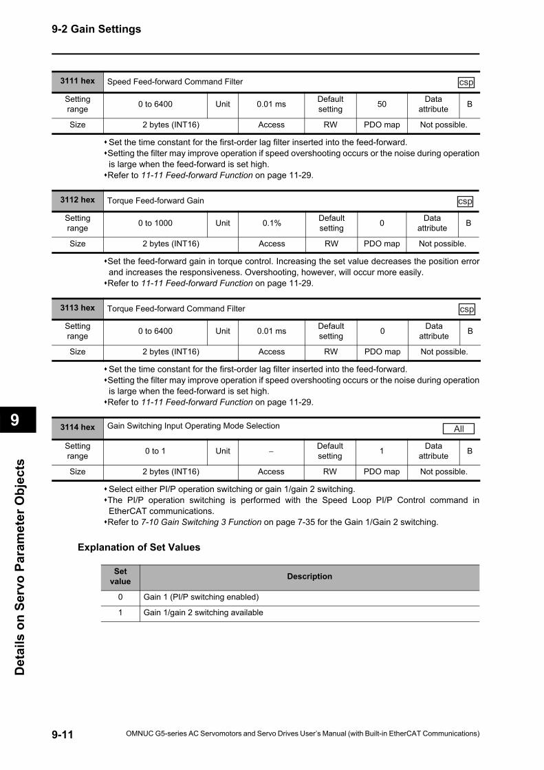
9-2 Gain Settings
9
Det
ails
on
Serv
o Pa
ram
eter
Obj
ects
Set the time constant for the first-order lag filter inserted into the feed-forward.Setting the filter may improve operation if speed overshooting occurs or the noise during operationis large when the feed-forward is set high.Refer to 11-11 Feed-forward Function on page 11-29.
Set the feed-forward gain in torque control. Increasing the set value decreases the position errorand increases the responsiveness. Overshooting, however, will occur more easily.Refer to 11-11 Feed-forward Function on page 11-29.
Set the time constant for the first-order lag filter inserted into the feed-forward.Setting the filter may improve operation if speed overshooting occurs or the noise during operationis large when the feed-forward is set high.Refer to 11-11 Feed-forward Function on page 11-29.
Select either PI/P operation switching or gain 1/gain 2 switching.The PI/P operation switching is performed with the Speed Loop PI/P Control command inEtherCAT communications.Refer to 7-10 Gain Switching 3 Function on page 7-35 for the Gain 1/Gain 2 switching.
Explanation of Set Values
3111 hex Speed Feed-forward Command Filter
Setting range 0 to 6400 Unit 0.01 ms Default
setting 50 Data attribute B
Size 2 bytes (INT16) Access RW PDO map Not possible.
csp
3112 hex Torque Feed-forward Gain
Setting range 0 to 1000 Unit 0.1% Default
setting 0 Data attribute B
Size 2 bytes (INT16) Access RW PDO map Not possible.
csp
3113 hex Torque Feed-forward Command Filter
Setting range 0 to 6400 Unit 0.01 ms Default
setting 0 Data attribute B
Size 2 bytes (INT16) Access RW PDO map Not possible.
csp
3114 hex Gain Switching Input Operating Mode Selection
Setting range 0 to 1 Unit − Default
setting 1 Data attribute B
Size 2 bytes (INT16) Access RW PDO map Not possible.
All
Set value Description
0 Gain 1 (PI/P switching enabled)
1 Gain 1/gain 2 switching available
9-11 OMNUC G5-series AC Servomotors and Servo Drives User’s Manual (with Built-in EtherCAT Communications)
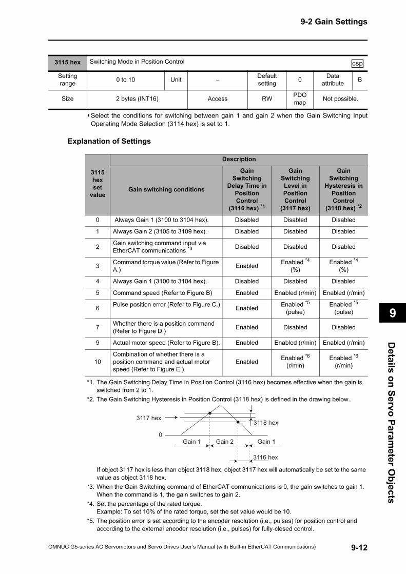
9-2 Gain Settings
9
Details on Servo Param
eter Objects
Select the conditions for switching between gain 1 and gain 2 when the Gain Switching InputOperating Mode Selection (3114 hex) is set to 1.
Explanation of Settings
*1. The Gain Switching Delay Time in Position Control (3116 hex) becomes effective when the gain is switched from 2 to 1.
*2. The Gain Switching Hysteresis in Position Control (3118 hex) is defined in the drawing below.
If object 3117 hex is less than object 3118 hex, object 3117 hex will automatically be set to the same value as object 3118 hex.
*3. When the Gain Switching command of EtherCAT communications is 0, the gain switches to gain 1. When the command is 1, the gain switches to gain 2.
*4. Set the percentage of the rated torque. Example: To set 10% of the rated torque, set the set value would be 10.
*5. The position error is set according to the encoder resolution (i.e., pulses) for position control and according to the external encoder resolution (i.e., pulses) for fully-closed control.
3115 hex Switching Mode in Position Control
Setting range 0 to 10 Unit − Default
setting 0 Data attribute B
Size 2 bytes (INT16) Access RW PDO map Not possible.
csp
3115 hex set
value
Description
Gain switching conditions
Gain Switching
Delay Time in Position Control
(3116 hex) *1
Gain Switching Level in Position Control
(3117 hex)
Gain Switching
Hysteresis in Position Control
(3118 hex) *2
0 Always Gain 1 (3100 to 3104 hex). Disabled Disabled Disabled
1 Always Gain 2 (3105 to 3109 hex). Disabled Disabled Disabled
2 Gain switching command input via EtherCAT communications *3 Disabled Disabled Disabled
3 Command torque value (Refer to Figure A.) Enabled Enabled *4
(%)Enabled *4
(%)
4 Always Gain 1 (3100 to 3104 hex). Disabled Disabled Disabled
5 Command speed (Refer to Figure B) Enabled Enabled (r/min) Enabled (r/min)
6 Pulse position error (Refer to Figure C.) Enabled Enabled *5(pulse)
Enabled *5(pulse)
7 Whether there is a position command (Refer to Figure D.) Enabled Disabled Disabled
9 Actual motor speed (Refer to Figure B). Enabled Enabled (r/min) Enabled (r/min)
10Combination of whether there is a position command and actual motor speed (Refer to Figure E.)
Enabled Enabled *6(r/min)
Enabled *6(r/min)
3117 hex
0
3118 hex
3116 hex
Gain 1 Gain 2 Gain 1
9-12OMNUC G5-series AC Servomotors and Servo Drives User’s Manual (with Built-in EtherCAT Communications)
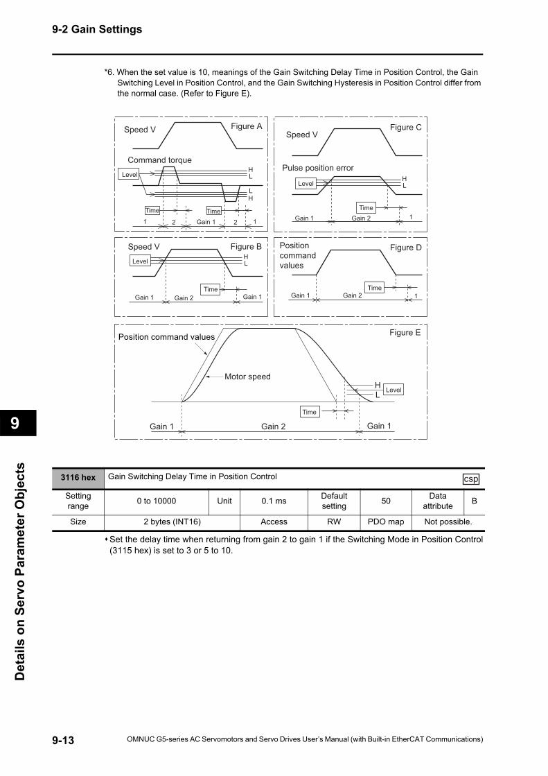
9-2 Gain Settings
9
Det
ails
on
Serv
o Pa
ram
eter
Obj
ects
*6. When the set value is 10, meanings of the Gain Switching Delay Time in Position Control, the Gain Switching Level in Position Control, and the Gain Switching Hysteresis in Position Control differ from the normal case. (Refer to Figure E).
Set the delay time when returning from gain 2 to gain 1 if the Switching Mode in Position Control(3115 hex) is set to 3 or 5 to 10.
HL
HL
HL
HL
Position command values
Position command values
Motor speedHL
Figure ASpeed V
Command torque
Time
1 2 2 1Gain 1
Figure CSpeed V
Gain 1 1Gain 2
Pulse position error
Level
Time
Figure D
Figure E
Gain 1 1Gain 2Time
Figure BSpeed V
Gain 1 Gain 1Gain 2Time
Gain 1 Gain 2
Time
Gain 1
Level
Level
Level
Time
3116 hex Gain Switching Delay Time in Position Control
Setting range 0 to 10000 Unit 0.1 ms Default
setting 50 Data attribute B
Size 2 bytes (INT16) Access RW PDO map Not possible.
csp
9-13 OMNUC G5-series AC Servomotors and Servo Drives User’s Manual (with Built-in EtherCAT Communications)
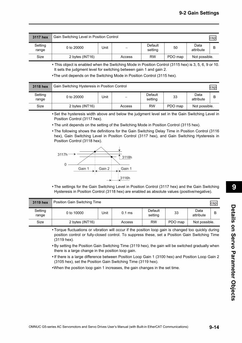
9-2 Gain Settings
9
Details on Servo Param
eter Objects
This object is enabled when the Switching Mode in Position Control (3115 hex) is 3, 5, 6, 9 or 10.It sets the judgment level for switching between gain 1 and gain 2. The unit depends on the Switching Mode in Position Control (3115 hex).
Set the hysteresis width above and below the judgment level set in the Gain Switching Level inPosition Control (3117 hex). The unit depends on the setting of the Switching Mode in Position Control (3115 hex).The following shows the definitions for the Gain Switching Delay Time in Position Control (3116hex), Gain Switching Level in Position Control (3117 hex), and Gain Switching Hysteresis inPosition Control (3118 hex).
The settings for the Gain Switching Level in Position Control (3117 hex) and the Gain SwitchingHysteresis in Position Control (3118 hex) are enabled as absolute values (positive/negative).
Torque fluctuations or vibration will occur if the position loop gain is changed too quickly duringposition control or fully-closed control. To suppress these, set a Position Gain Switching Time(3119 hex). By setting the Position Gain Switching Time (3119 hex), the gain will be switched gradually whenthere is a large change in the position loop gain. If there is a large difference between Position Loop Gain 1 (3100 hex) and Position Loop Gain 2(3105 hex), set the Position Gain Switching Time (3119 hex). When the position loop gain 1 increases, the gain changes in the set time.
3117 hex Gain Switching Level in Position Control
Setting range 0 to 20000 Unit − Default
setting 50 Data attribute B
Size 2 bytes (INT16) Access RW PDO map Not possible.
csp
3118 hex Gain Switching Hysteresis in Position Control
Setting range 0 to 20000 Unit − Default
setting 33 Data attribute B
Size 2 bytes (INT16) Access RW PDO map Not possible.
csp
3117h
0
3118h
3116h
Gain 1 Gain 2 Gain 1
3119 hex Position Gain Switching Time
Setting range 0 to 10000 Unit 0.1 ms Default
setting 33 Data attribute B
Size 2 bytes (INT16) Access RW PDO map Not possible.
csp
9-14OMNUC G5-series AC Servomotors and Servo Drives User’s Manual (with Built-in EtherCAT Communications)
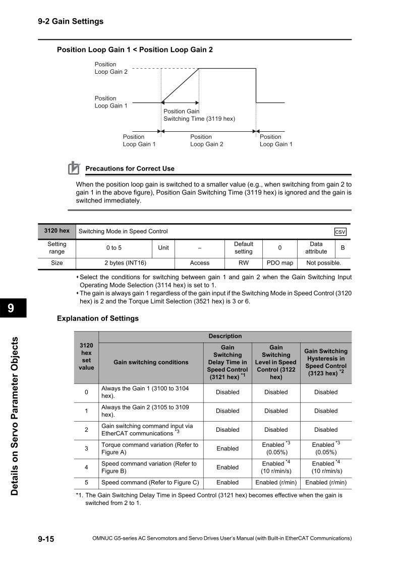
9-2 Gain Settings
9
Det
ails
on
Serv
o Pa
ram
eter
Obj
ects
Position Loop Gain 1 < Position Loop Gain 2
Precautions for Correct Use
When the position loop gain is switched to a smaller value (e.g., when switching from gain 2 togain 1 in the above figure), Position Gain Switching Time (3119 hex) is ignored and the gain isswitched immediately.
Select the conditions for switching between gain 1 and gain 2 when the Gain Switching InputOperating Mode Selection (3114 hex) is set to 1.The gain is always gain 1 regardless of the gain input if the Switching Mode in Speed Control (3120hex) is 2 and the Torque Limit Selection (3521 hex) is 3 or 6.
Explanation of Settings
*1. The Gain Switching Delay Time in Speed Control (3121 hex) becomes effective when the gain is switched from 2 to 1.
3120 hex Switching Mode in Speed Control
Setting range 0 to 5 Unit − Default
setting 0 Data attribute B
Size 2 bytes (INT16) Access RW PDO map Not possible.
Position Gain Switching Time (3119 hex)
Position Loop Gain 1
Position Loop Gain 2
Position Loop Gain 1
Position Loop Gain 1
Position Loop Gain 2
csv
3120 hex set
value
Description
Gain switching conditions
Gain Switching
Delay Time in Speed Control (3121 hex) *1
Gain Switching
Level in Speed Control (3122
hex)
Gain Switching Hysteresis in
Speed Control (3123 hex) *2
0 Always the Gain 1 (3100 to 3104 hex). Disabled Disabled Disabled
1 Always the Gain 2 (3105 to 3109 hex). Disabled Disabled Disabled
2 Gain switching command input via EtherCAT communications *3 Disabled Disabled Disabled
3 Torque command variation (Refer to Figure A) Enabled Enabled *3
(0.05%)Enabled *3
(0.05%)
4 Speed command variation (Refer to Figure B) Enabled Enabled *4
(10 r/min/s)Enabled *4
(10 r/min/s)
5 Speed command (Refer to Figure C) Enabled Enabled (r/min) Enabled (r/min)
9-15 OMNUC G5-series AC Servomotors and Servo Drives User’s Manual (with Built-in EtherCAT Communications)
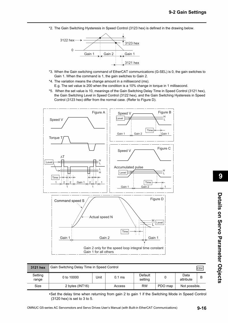
9-2 Gain Settings
9
Details on Servo Param
eter Objects
*2. The Gain Switching Hysteresis in Speed Control (3123 hex) is defined in the drawing below.
*3. When the Gain switching command of EtherCAT communications (G-SEL) is 0, the gain switches to Gain 1. When the command is 1, the gain switches to Gain 2.
*4. The variation means the change amount in a millisecond (ms).E.g. The set value is 200 when the condition is a 10% change in torque in 1 millisecond.
*5. When the set value is 10, meanings of the Gain Switching Delay Time in Speed Control (3121 hex), the Gain Switching Level in Speed Control (3122 hex), and the Gain Switching Hysteresis in Speed Control (3123 hex) differ from the normal case. (Refer to Figure D).
Set the delay time when returning from gain 2 to gain 1 if the Switching Mode in Speed Control(3120 hex) is set to 3 to 5.
3121 hex Gain Switching Delay Time in Speed Control
Setting range 0 to 10000 Unit 0.1 ms Default
setting 0 Data attribute B
Size 2 bytes (INT16) Access RW PDO map Not possible.
3122 hex
0
3123 hex
3121 hex
Gain 1 Gain 2 Gain 1
HL
HL
HL
HL
Figure A
Speed V
Torque T
Time
11
2 2 2 21
1Gain 1
Figure CSpeed V
Gain 1 1Gain 2
Accumulated pulseLevel
Time
Figure BSpeed V
Gain 1 Gain 1Gain 2Time
Command speed S
Gain 1 Gain 2
Actual speed N
Time
HL
Gain 1
Gain 2 only for the speed loop integral time constantGain 1 for all others
Figure D
Level
Level
Level
csv
9-16OMNUC G5-series AC Servomotors and Servo Drives User’s Manual (with Built-in EtherCAT Communications)
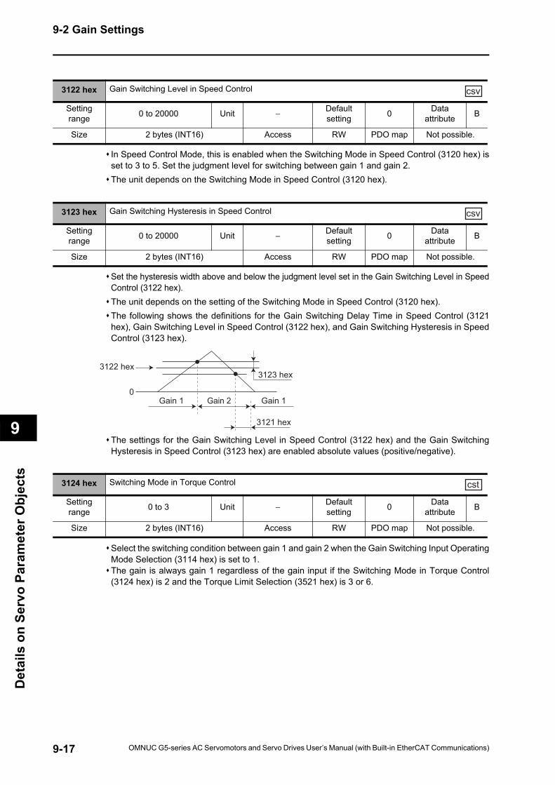
9-2 Gain Settings
9
Det
ails
on
Serv
o Pa
ram
eter
Obj
ects
In Speed Control Mode, this is enabled when the Switching Mode in Speed Control (3120 hex) isset to 3 to 5. Set the judgment level for switching between gain 1 and gain 2. The unit depends on the Switching Mode in Speed Control (3120 hex).
Set the hysteresis width above and below the judgment level set in the Gain Switching Level in SpeedControl (3122 hex). The unit depends on the setting of the Switching Mode in Speed Control (3120 hex).The following shows the definitions for the Gain Switching Delay Time in Speed Control (3121hex), Gain Switching Level in Speed Control (3122 hex), and Gain Switching Hysteresis in SpeedControl (3123 hex).
The settings for the Gain Switching Level in Speed Control (3122 hex) and the Gain SwitchingHysteresis in Speed Control (3123 hex) are enabled absolute values (positive/negative).
Select the switching condition between gain 1 and gain 2 when the Gain Switching Input OperatingMode Selection (3114 hex) is set to 1.The gain is always gain 1 regardless of the gain input if the Switching Mode in Torque Control(3124 hex) is 2 and the Torque Limit Selection (3521 hex) is 3 or 6.
3122 hex Gain Switching Level in Speed Control
Setting range 0 to 20000 Unit − Default
setting 0 Data attribute B
Size 2 bytes (INT16) Access RW PDO map Not possible.
3123 hex Gain Switching Hysteresis in Speed Control
Setting range 0 to 20000 Unit − Default
setting 0 Data attribute B
Size 2 bytes (INT16) Access RW PDO map Not possible.
3124 hex Switching Mode in Torque Control
Setting range 0 to 3 Unit − Default
setting 0 Data attribute B
Size 2 bytes (INT16) Access RW PDO map Not possible.
csv
csv
3122 hex
0
3123 hex
3121 hex
Gain 1 Gain 2 Gain 1
cst
9-17 OMNUC G5-series AC Servomotors and Servo Drives User’s Manual (with Built-in EtherCAT Communications)
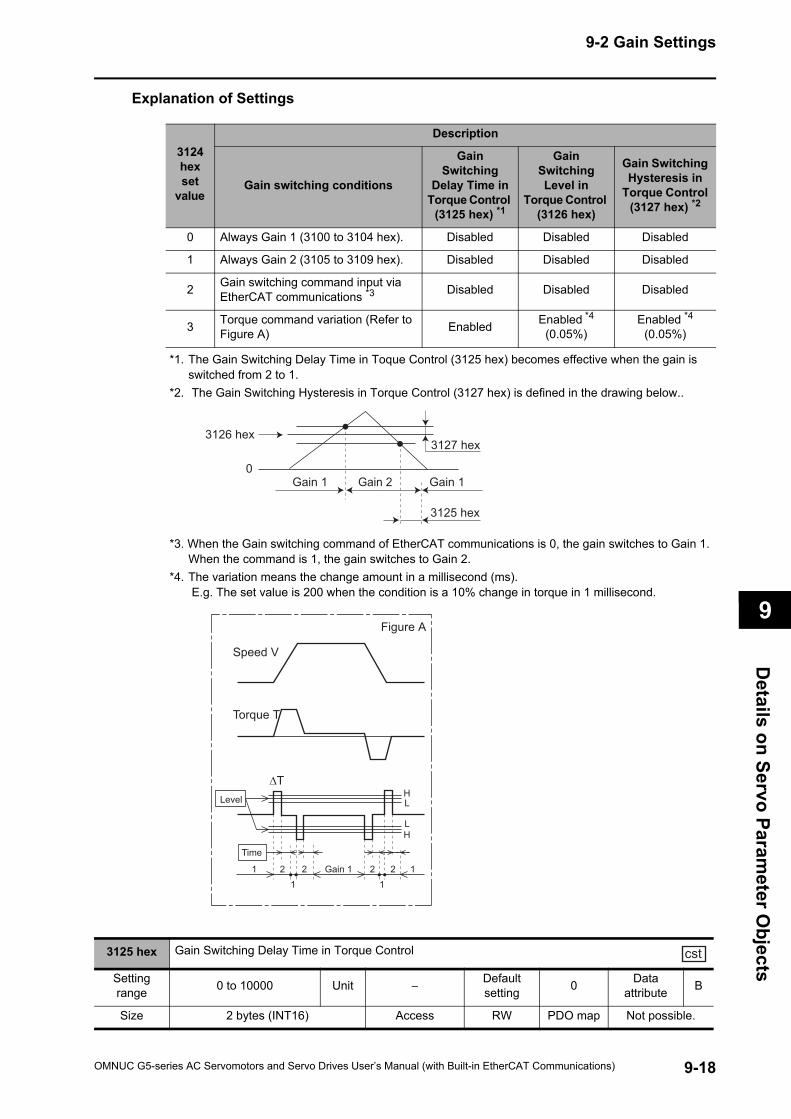
9-2 Gain Settings
9
Details on Servo Param
eter Objects
Explanation of Settings
*1. The Gain Switching Delay Time in Toque Control (3125 hex) becomes effective when the gain is switched from 2 to 1.
*2. The Gain Switching Hysteresis in Torque Control (3127 hex) is defined in the drawing below..
*3. When the Gain switching command of EtherCAT communications is 0, the gain switches to Gain 1. When the command is 1, the gain switches to Gain 2.
*4. The variation means the change amount in a millisecond (ms). E.g. The set value is 200 when the condition is a 10% change in torque in 1 millisecond.
3124 hex set
value
Description
Gain switching conditions
Gain Switching
Delay Time in Torque Control
(3125 hex) *1
Gain Switching Level in
Torque Control (3126 hex)
Gain Switching Hysteresis in
Torque Control (3127 hex) *2
0 Always Gain 1 (3100 to 3104 hex). Disabled Disabled Disabled
1 Always Gain 2 (3105 to 3109 hex). Disabled Disabled Disabled
2 Gain switching command input via EtherCAT communications *3 Disabled Disabled Disabled
3 Torque command variation (Refer to Figure A) Enabled Enabled *4
(0.05%)Enabled *4
(0.05%)
3125 hex Gain Switching Delay Time in Torque Control
Setting range 0 to 10000 Unit − Default
setting 0 Data attribute B
Size 2 bytes (INT16) Access RW PDO map Not possible.
3126 hex
0
3127 hex
3125 hex
Gain 1 Gain 2 Gain 1
HL
HL
Figure A
Speed V
Torque T
Time
11
2 2 2 21
1Gain 1
Level
cst
9-18OMNUC G5-series AC Servomotors and Servo Drives User’s Manual (with Built-in EtherCAT Communications)
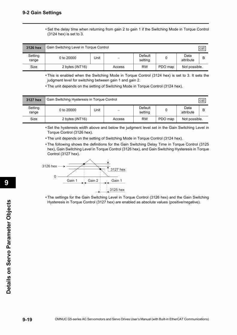
9-2 Gain Settings
9
Det
ails
on
Serv
o Pa
ram
eter
Obj
ects
Set the delay time when returning from gain 2 to gain 1 if the Switching Mode in Torque Control(3124 hex) is set to 3.
This is enabled when the Switching Mode in Torque Control (3124 hex) is set to 3. It sets thejudgment level for switching between gain 1 and gain 2. The unit depends on the setting of Switching Mode in Torque Control (3124 hex).
Set the hysteresis width above and below the judgment level set in the Gain Switching Level inTorque Control (3126 hex). The unit depends on the setting of Switching Mode in Torque Control (3124 hex).The following shows the definitions for the Gain Switching Delay Time in Torque Control (3125hex), Gain Switching Level in Torque Control (3126 hex), and Gain Switching Hysteresis in TorqueControl (3127 hex).
The settings for the Gain Switching Level in Torque Control (3126 hex) and the Gain SwitchingHysteresis in Torque Control (3127 hex) are enabled as absolute values (positive/negative).
3126 hex Gain Switching Level in Torque Control
Setting range 0 to 20000 Unit − Default
setting 0 Data attribute B
Size 2 bytes (INT16) Access RW PDO map Not possible.
3127 hex Gain Switching Hysteresis in Torque Control
Setting range 0 to 20000 Unit − Default
setting 0 Data attribute B
Size 2 bytes (INT16) Access RW PDO map Not possible.
cst
cst
3126 hex
0
3127 hex
3125 hex
Gain 1 Gain 2 Gain 1
9-19 OMNUC G5-series AC Servomotors and Servo Drives User’s Manual (with Built-in EtherCAT Communications)
9-3 Vibration Suppression Settings
9
Details on Servo Param
eter Objects
9-3 Vibration Suppression Settings
Set the operation of the adaptive filter.Refer to 11-6 Adaptive Filter on page 11-18.
Explanation of Set Values
Set the frequency of resonance suppression notch filter 1. The notch filter function is disabled if this object is set to 5000. Refer to 11-7 Notch Filters on page 11-21.
Set the width of resonance suppression notch filter 1 to one of 20 levels. Increasing the setting value widens the notch width. Normally, use the default set value. Refer to 11-7 Notch Filters on page 11-21.
Set the notch depth of resonance suppression notch filter 1. Increasing the setting value shortens the notch depth and the phase lag. Refer to 11-7 Notch Filters on page 11-21.
3200 hex Adaptive Filter Selection
Setting range 0 to 4 Unit − Default
setting 0 Data attribute B
Size 2 bytes (INT16) Access RW PDO map Not possible.
csp
Set value Description
0 Adaptive filter disabled
1 One adaptive filter is enabled. The objects related to notch filter 3 are automatically updated.
2 Two adaptive filters are enabled. The objects related to notch filters 3 and 4 are updated.
3 For use by manufacturer. Do not use this setting.
4 Adaptive result is cleared. Objects related to notch filters 3 and 4 are disabled and the adaptive result is cleared.
3201 hex Notch 1 Frequency Setting
Setting range 50 to 5000 Unit Hz Default
setting 5000 Data attribute B
Size 2 bytes (INT16) Access RW PDO map Not possible.
All
3202 hex Notch 1 Width Setting
Setting range 0 to 20 Unit − Default
setting 2 Data attribute B
Size 2 bytes (INT16) Access RW PDO map Not possible.
All
3203 hex Notch 1 Depth Setting
Setting range 0 to 99 Unit − Default
setting 0 Data attribute B
Size 2 bytes (INT16) Access RW PDO map Not possible.
All
9-20OMNUC G5-series AC Servomotors and Servo Drives User’s Manual (with Built-in EtherCAT Communications)
9-3 Vibration Suppression Settings
9
Det
ails
on
Serv
o Pa
ram
eter
Obj
ects
Set the notch frequency of resonance suppression notch filter 2. The notch filter function is disabled if this object is set to 5000. Refer to 11-7 Notch Filters on page 11-21.
Select the notch width of resonance suppression notch filter 2. Increasing the setting value widens the notch width. Normally, use the default set value. Refer to 11-7 Notch Filters on page 11-21.
Set the notch depth of resonance suppression notch filter 2. Increasing the setting value shortens the notch depth and the phase lag. Refer to 11-7 Notch Filters on page 11-21.
Set the notch frequency of resonance suppression notch filter 3. The notch filter function is disabled if this object is set to 5000. While the adaptive filter is enabled, the resonance frequency 1 that is assumed by the adaptivefilter is automatically set. If no resonance point is found, the value 5000 is set. Refer to 11-6 Adaptive Filter on page 11-18 and 11-7 Notch Filters on page 11-21.
Select the notch width of resonance suppression notch filter 3. Increasing the setting value widens the notch width. Normally, use the default set value. While the adaptive filter is enabled, this object is set automatically. Refer to 11-6 Adaptive Filter on page 11-18 and 11-7 Notch Filters on page 11-21.
3204 hex Notch 2 Frequency Setting
Setting range 50 to 5000 Unit Hz Default
setting 5000 Data attribute B
Size 2 bytes (INT16) Access RW PDO map Not possible.
All
3205 hex Notch 2 Width Setting
Setting range 0 to 20 Unit − Default
setting 2 Data attribute B
Size 2 bytes (INT16) Access RW PDO map Not possible.
3206 hex Notch 2 Depth Setting
Setting range 0 to 99 Unit − Default
setting 0 Data attribute B
Size 2 bytes (INT16) Access RW PDO map Not possible.
3207 hex Notch 3 Frequency Setting
Setting range 50 to 5000 Unit Hz Default
setting 5000 Data attribute B
Size 2 bytes (INT16) Access RW PDO map Not possible.
3208 hex Notch 3 Width Setting
Setting range 0 to 20 Unit − Default
setting 2 Data attribute B
Size 2 bytes (INT16) Access RW PDO map Not possible.
3209 hex Notch 3 Depth Setting
Setting range 0 to 99 Unit − Default
setting 0 Data attribute B
Size 2 bytes (INT16) Access RW PDO map Not possible.
All
All
All
All
All
9-21 OMNUC G5-series AC Servomotors and Servo Drives User’s Manual (with Built-in EtherCAT Communications)
9-3 Vibration Suppression Settings
9
Details on Servo Param
eter Objects
Set the notch depth of resonance suppression notch filter 3. Increasing the setting value shortens the notch depth and the phase lag. While the adaptive filter is enabled, this object is set automatically. Refer to 11-6 Adaptive Filter on page 11-18 and 11-7 Notch Filters on page 11-21.
Set the notch frequency of resonance suppression notch filter 4. The notch filter function is disabled if this object is set to 5000. While two adaptive filters are enabled, the resonance frequency 2 that is assumed by the adaptivefilter is automatically set. If no resonance point is found, the value 5000 is set. Refer to 11-6 Adaptive Filter on page 11-18 and 11-7 Notch Filters on page 11-21.
Select the notch width of resonance suppression notch filter 4. Increasing the setting value widens the notch width. Normally, use the default set value. This object is automatically set when two adaptive filters are enabled. Refer to 11-6 Adaptive Filter on page 11-18 and 11-7 Notch Filters on page 11-21.
Set the notch depth of resonance suppression notch filter 4. Increasing the setting value shortens the notch depth and the phase lag. While the adaptive filter is enabled, this object is set automatically. Refer to 11-6 Adaptive Filter on page 11-18 and 11-7 Notch Filters on page 11-21.
Set the method to switch among four damping control filters.
Explanation of Set Values
*1 The set value 1 and 2 are for manufacturer's use only. Users are not allowed to set 1 and 2 for this object.
3210 hex Notch 4 Frequency Setting
Setting range 50 to 5000 Unit Hz Default
setting 5000 Data attribute B
Size 2 bytes (INT16) Access RW PDO map Not possible.
All
3211 hex Notch 4 Width Setting
Setting range 0 to 20 Unit − Default
setting 2 Data attribute B
Size 2 bytes (INT16) Access RW PDO map Not possible.
All
3212 hex Notch 4 Depth Setting
Setting range 0 to 99 Unit − Default
setting 0 Data attribute B
Size 2 bytes (INT16) Access RW PDO map Not possible.
All
3213 hex Damping Filter Selection
Setting range 0 to 3 Unit − Default
setting 0 Data attribute B
Size 2 bytes (INT16) Access RW PDO map Not possible.
csp
Set value Explanation
0 Up two damping filters, damping filters 1 and 2, can be used at the same time.
1 Reserved for manufacturer use *1
2 Reserved for manufacturer use *1
3The damping filters are switched with position command direction.• Forward direction: Damping filters 1 / 3 enabled• Reverse direction: Damping filters 2 / 4 enabled
9-22OMNUC G5-series AC Servomotors and Servo Drives User’s Manual (with Built-in EtherCAT Communications)
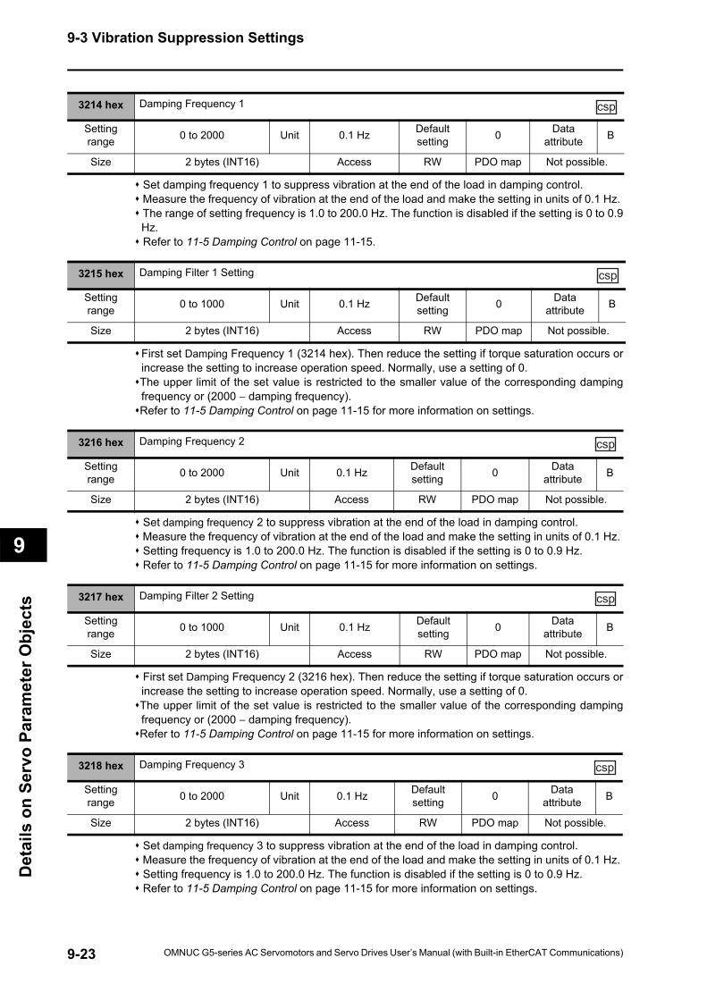
9-3 Vibration Suppression Settings
9
Det
ails
on
Serv
o Pa
ram
eter
Obj
ects
Set damping frequency 1 to suppress vibration at the end of the load in damping control. Measure the frequency of vibration at the end of the load and make the setting in units of 0.1 Hz. The range of setting frequency is 1.0 to 200.0 Hz. The function is disabled if the setting is 0 to 0.9Hz. Refer to 11-5 Damping Control on page 11-15.
First set Damping Frequency 1 (3214 hex). Then reduce the setting if torque saturation occurs orincrease the setting to increase operation speed. Normally, use a setting of 0.The upper limit of the set value is restricted to the smaller value of the corresponding dampingfrequency or (2000 − damping frequency).Refer to 11-5 Damping Control on page 11-15 for more information on settings.
Set damping frequency 2 to suppress vibration at the end of the load in damping control. Measure the frequency of vibration at the end of the load and make the setting in units of 0.1 Hz. Setting frequency is 1.0 to 200.0 Hz. The function is disabled if the setting is 0 to 0.9 Hz. Refer to 11-5 Damping Control on page 11-15 for more information on settings.
First set Damping Frequency 2 (3216 hex). Then reduce the setting if torque saturation occurs orincrease the setting to increase operation speed. Normally, use a setting of 0.The upper limit of the set value is restricted to the smaller value of the corresponding dampingfrequency or (2000 − damping frequency).Refer to 11-5 Damping Control on page 11-15 for more information on settings.
Set damping frequency 3 to suppress vibration at the end of the load in damping control. Measure the frequency of vibration at the end of the load and make the setting in units of 0.1 Hz. Setting frequency is 1.0 to 200.0 Hz. The function is disabled if the setting is 0 to 0.9 Hz. Refer to 11-5 Damping Control on page 11-15 for more information on settings.
3214 hex Damping Frequency 1
Setting range 0 to 2000 Unit 0.1 Hz Default
setting 0 Data attribute B
Size 2 bytes (INT16) Access RW PDO map Not possible.
csp
3215 hex Damping Filter 1 Setting
Setting range 0 to 1000 Unit 0.1 Hz Default
setting 0 Data attribute B
Size 2 bytes (INT16) Access RW PDO map Not possible.
csp
3216 hex Damping Frequency 2
Setting range 0 to 2000 Unit 0.1 Hz Default
setting 0 Data attribute B
Size 2 bytes (INT16) Access RW PDO map Not possible.
csp
3217 hex Damping Filter 2 Setting
Setting range 0 to 1000 Unit 0.1 Hz Default
setting 0 Data attribute B
Size 2 bytes (INT16) Access RW PDO map Not possible.
csp
3218 hex Damping Frequency 3
Setting range 0 to 2000 Unit 0.1 Hz Default
setting 0 Data attribute B
Size 2 bytes (INT16) Access RW PDO map Not possible.
csp
9-23 OMNUC G5-series AC Servomotors and Servo Drives User’s Manual (with Built-in EtherCAT Communications)
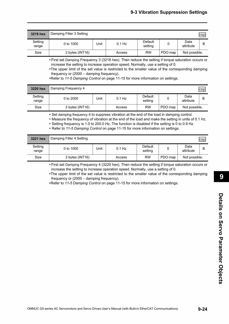
9-3 Vibration Suppression Settings
9
Details on Servo Param
eter Objects
First set Damping Frequency 3 (3218 hex). Then reduce the setting if torque saturation occurs orincrease the setting to increase operation speed. Normally, use a setting of 0.The upper limit of the set value is restricted to the smaller value of the corresponding dampingfrequency or (2000 − damping frequency).Refer to 11-5 Damping Control on page 11-15 for more information on settings.
Set damping frequency 4 to suppress vibration at the end of the load in damping control. Measure the frequency of vibration at the end of the load and make the setting in units of 0.1 Hz. Setting frequency is 1.0 to 200.0 Hz. The function is disabled if the setting is 0 to 0.9 Hz. Refer to 11-5 Damping Control on page 11-15 for more information on settings.
First set Damping Frequency 4 (3220 hex). Then reduce the setting if torque saturation occurs orincrease the setting to increase operation speed. Normally, use a setting of 0.The upper limit of the set value is restricted to the smaller value of the corresponding dampingfrequency or (2000 − damping frequency).Refer to 11-5 Damping Control on page 11-15 for more information on settings.
3219 hex Damping Filter 3 Setting
Setting range 0 to 1000 Unit 0.1 Hz Default
setting 0 Data attribute B
Size 2 bytes (INT16) Access RW PDO map Not possible.
csp
3220 hex Damping Frequency 4
Setting range 0 to 2000 Unit 0.1 Hz Default
setting 0 Data attribute B
Size 2 bytes (INT16) Access RW PDO map Not possible.
csp
3221 hex Damping Filter 4 Setting
Setting range 0 to 1000 Unit 0.1 Hz Default
setting 0 Data attribute B
Size 2 bytes (INT16) Access RW PDO map Not possible.
csp
9-24OMNUC G5-series AC Servomotors and Servo Drives User’s Manual (with Built-in EtherCAT Communications)
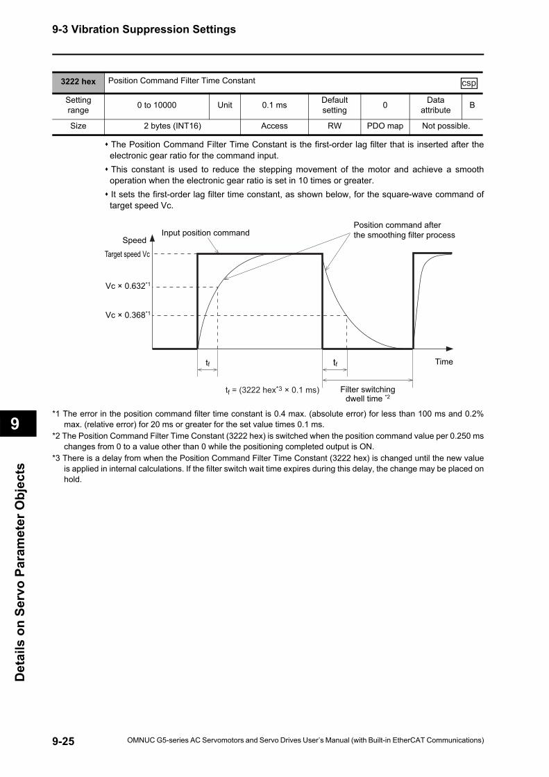
9-3 Vibration Suppression Settings
9
Det
ails
on
Serv
o Pa
ram
eter
Obj
ects
The Position Command Filter Time Constant is the first-order lag filter that is inserted after theelectronic gear ratio for the command input. This constant is used to reduce the stepping movement of the motor and achieve a smoothoperation when the electronic gear ratio is set in 10 times or greater. It sets the first-order lag filter time constant, as shown below, for the square-wave command oftarget speed Vc.
*1 The error in the position command filter time constant is 0.4 max. (absolute error) for less than 100 ms and 0.2%max. (relative error) for 20 ms or greater for the set value times 0.1 ms.
*2 The Position Command Filter Time Constant (3222 hex) is switched when the position command value per 0.250 mschanges from 0 to a value other than 0 while the positioning completed output is ON.
*3 There is a delay from when the Position Command Filter Time Constant (3222 hex) is changed until the new valueis applied in internal calculations. If the filter switch wait time expires during this delay, the change may be placed onhold.
3222 hex Position Command Filter Time Constant
Setting range 0 to 10000 Unit 0.1 ms Default
setting 0 Data attribute B
Size 2 bytes (INT16) Access RW PDO map Not possible.
csp
tf = (3222 hex*3 × 0.1 ms)
Input position command
tf
Position command afterthe smoothing filter process
tf
Filter switchingdwell time *2
Time
Speed
Target speed Vc
Vc × 0.632*1
Vc × 0.368*1
9-25 OMNUC G5-series AC Servomotors and Servo Drives User’s Manual (with Built-in EtherCAT Communications)
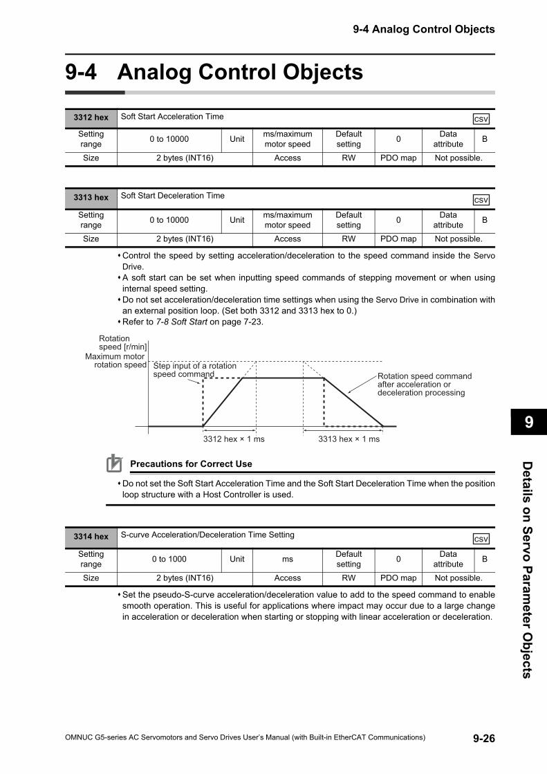
9-4 Analog Control Objects
9
Details on Servo Param
eter Objects
9-4 Analog Control Objects
Control the speed by setting acceleration/deceleration to the speed command inside the ServoDrive. A soft start can be set when inputting speed commands of stepping movement or when usinginternal speed setting.Do not set acceleration/deceleration time settings when using the Servo Drive in combination withan external position loop. (Set both 3312 and 3313 hex to 0.)Refer to 7-8 Soft Start on page 7-23.
Precautions for Correct Use
Do not set the Soft Start Acceleration Time and the Soft Start Deceleration Time when the positionloop structure with a Host Controller is used.
Set the pseudo-S-curve acceleration/deceleration value to add to the speed command to enablesmooth operation. This is useful for applications where impact may occur due to a large changein acceleration or deceleration when starting or stopping with linear acceleration or deceleration.
3312 hex Soft Start Acceleration Time
Setting range 0 to 10000 Unit ms/maximum
motor speedDefault setting 0 Data
attribute B
Size 2 bytes (INT16) Access RW PDO map Not possible.
csv
3313 hex Soft Start Deceleration Time
Setting range 0 to 10000 Unit ms/maximum
motor speedDefault setting 0 Data
attribute B
Size 2 bytes (INT16) Access RW PDO map Not possible.
csv
Rotation speed [r/min]
Maximum motor rotation speed Step input of a rotation
speed command Rotation speed command after acceleration or deceleration processing
3312 hex × 1 ms 3313 hex × 1 ms
3314 hex S-curve Acceleration/Deceleration Time Setting
Setting range 0 to 1000 Unit ms Default
setting 0 Data attribute B
Size 2 bytes (INT16) Access RW PDO map Not possible.
csv
9-26OMNUC G5-series AC Servomotors and Servo Drives User’s Manual (with Built-in EtherCAT Communications)
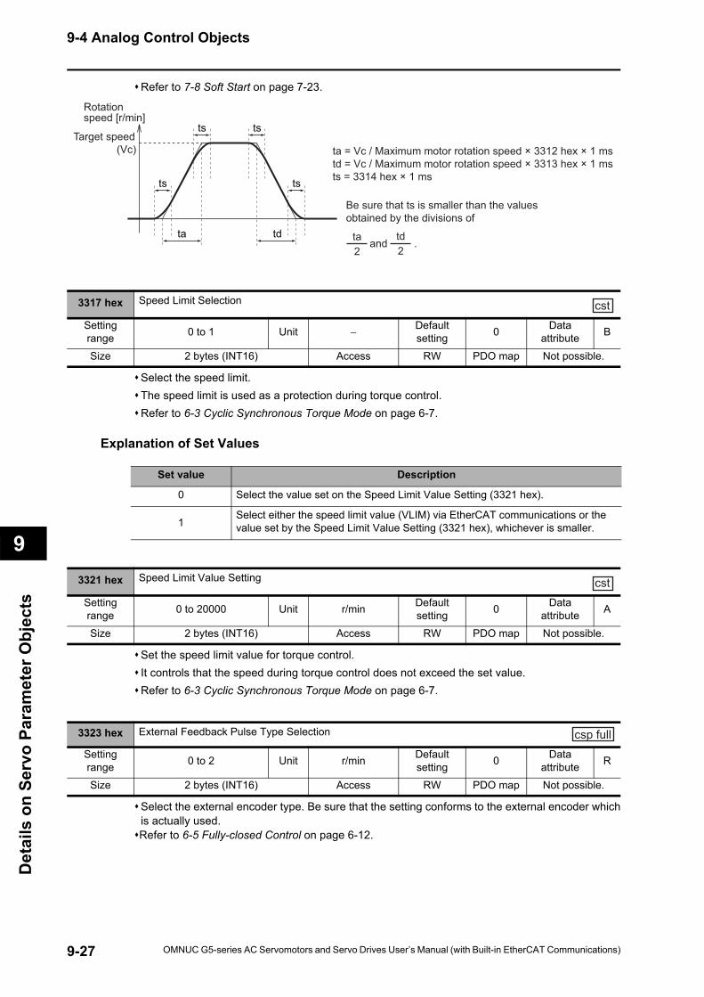
9-4 Analog Control Objects
9
Det
ails
on
Serv
o Pa
ram
eter
Obj
ects
Refer to 7-8 Soft Start on page 7-23.
Select the speed limit.The speed limit is used as a protection during torque control.Refer to 6-3 Cyclic Synchronous Torque Mode on page 6-7.
Explanation of Set Values
Set the speed limit value for torque control.It controls that the speed during torque control does not exceed the set value.Refer to 6-3 Cyclic Synchronous Torque Mode on page 6-7.
Select the external encoder type. Be sure that the setting conforms to the external encoder whichis actually used.Refer to 6-5 Fully-closed Control on page 6-12.
ta td
ts ts
tsts
Rotation speed [r/min]
Target speed(Vc) ta = Vc / Maximum motor rotation speed × 3312 hex × 1 ms
td = Vc / Maximum motor rotation speed × 3313 hex × 1 msts = 3314 hex × 1 ms
Be sure that ts is smaller than the values obtained by the divisions of
and .2ta
2td
3317 hex Speed Limit Selection
Setting range 0 to 1 Unit − Default
setting 0 Data attribute B
Size 2 bytes (INT16) Access RW PDO map Not possible.
cst
Set value Description
0 Select the value set on the Speed Limit Value Setting (3321 hex).
1Select either the speed limit value (VLIM) via EtherCAT communications or the value set by the Speed Limit Value Setting (3321 hex), whichever is smaller.
3321 hex Speed Limit Value Setting
Setting range 0 to 20000 Unit r/min Default
setting 0 Data attribute A
Size 2 bytes (INT16) Access RW PDO map Not possible.
cst
3323 hex External Feedback Pulse Type Selection
Setting range 0 to 2 Unit r/min Default
setting 0 Data attribute R
Size 2 bytes (INT16) Access RW PDO map Not possible.
csp full
9-27 OMNUC G5-series AC Servomotors and Servo Drives User’s Manual (with Built-in EtherCAT Communications)
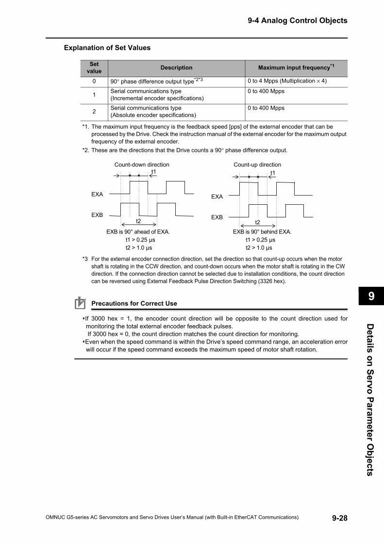
9-4 Analog Control Objects
9
Details on Servo Param
eter Objects
Explanation of Set Values
*1. The maximum input frequency is the feedback speed [pps] of the external encoder that can be processed by the Drive. Check the instruction manual of the external encoder for the maximum output frequency of the external encoder.
*2. These are the directions that the Drive counts a 90° phase difference output.
*3 For the external encoder connection direction, set the direction so that count-up occurs when the motor shaft is rotating in the CCW direction, and count-down occurs when the motor shaft is rotating in the CW direction. If the connection direction cannot be selected due to installation conditions, the count direction can be reversed using External Feedback Pulse Direction Switching (3326 hex).
Precautions for Correct Use
If 3000 hex = 1, the encoder count direction will be opposite to the count direction used formonitoring the total external encoder feedback pulses. If 3000 hex = 0, the count direction matches the count direction for monitoring.Even when the speed command is within the Drive’s speed command range, an acceleration errorwill occur if the speed command exceeds the maximum speed of motor shaft rotation.
Set value Description Maximum input frequency*1
0 90° phase difference output type*2*3 0 to 4 Mpps (Multiplication × 4)
1 Serial communications type(Incremental encoder specifications)
0 to 400 Mpps
2 Serial communications type(Absolute encoder specifications)
0 to 400 Mpps
Count-down direction Count-up direction
EXB is 90° ahead of EXA. t1 > 0.25 µs t2 > 1.0 µs
EXB is 90° behind EXA. t1 > 0.25 µst2 > 1.0 µs
t1
t2
t1
t2
EXA
EXB
EXA
EXB
9-28OMNUC G5-series AC Servomotors and Servo Drives User’s Manual (with Built-in EtherCAT Communications)
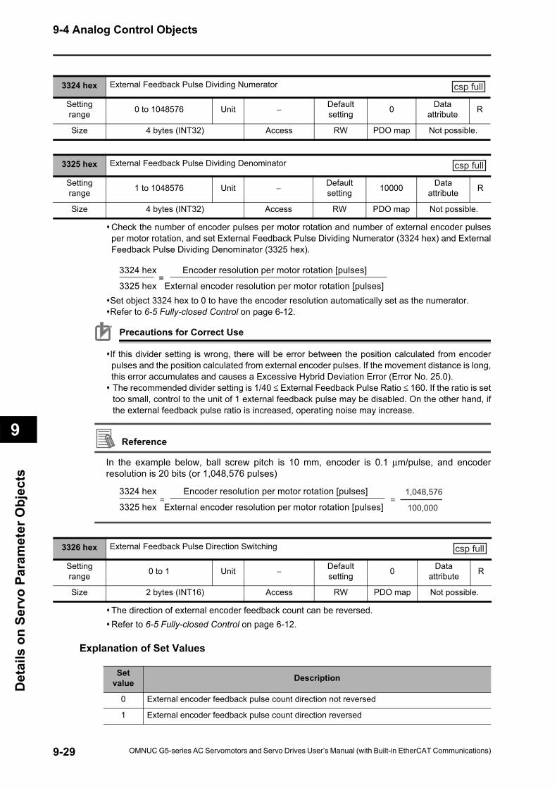
9-4 Analog Control Objects
9
Det
ails
on
Serv
o Pa
ram
eter
Obj
ects
Check the number of encoder pulses per motor rotation and number of external encoder pulsesper motor rotation, and set External Feedback Pulse Dividing Numerator (3324 hex) and ExternalFeedback Pulse Dividing Denominator (3325 hex).
Set object 3324 hex to 0 to have the encoder resolution automatically set as the numerator.Refer to 6-5 Fully-closed Control on page 6-12.
Precautions for Correct Use
If this divider setting is wrong, there will be error between the position calculated from encoderpulses and the position calculated from external encoder pulses. If the movement distance is long,this error accumulates and causes a Excessive Hybrid Deviation Error (Error No. 25.0).The recommended divider setting is 1/40 ≤ External Feedback Pulse Ratio ≤ 160. If the ratio is settoo small, control to the unit of 1 external feedback pulse may be disabled. On the other hand, ifthe external feedback pulse ratio is increased, operating noise may increase.
Reference
In the example below, ball screw pitch is 10 mm, encoder is 0.1 µm/pulse, and encoderresolution is 20 bits (or 1,048,576 pulses)
The direction of external encoder feedback count can be reversed.Refer to 6-5 Fully-closed Control on page 6-12.
Explanation of Set Values
3324 hex External Feedback Pulse Dividing Numerator
Setting range 0 to 1048576 Unit − Default
setting 0 Data attribute R
Size 4 bytes (INT32) Access RW PDO map Not possible.
csp full
3325 hex External Feedback Pulse Dividing Denominator
Setting range 1 to 1048576 Unit − Default
setting 10000 Data attribute R
Size 4 bytes (INT32) Access RW PDO map Not possible.
csp full
=Encoder resolution per motor rotation [pulses]
External encoder resolution per motor rotation [pulses]
3324 hex
3325 hex
=Encoder resolution per motor rotation [pulses]
External encoder resolution per motor rotation [pulses]
3324 hex
3325 hex 100,000
1,048,576=
3326 hex External Feedback Pulse Direction Switching
Setting range 0 to 1 Unit − Default
setting 0 Data attribute R
Size 2 bytes (INT16) Access RW PDO map Not possible.
csp full
Set value Description
0 External encoder feedback pulse count direction not reversed
1 External encoder feedback pulse count direction reversed
9-29 OMNUC G5-series AC Servomotors and Servo Drives User’s Manual (with Built-in EtherCAT Communications)
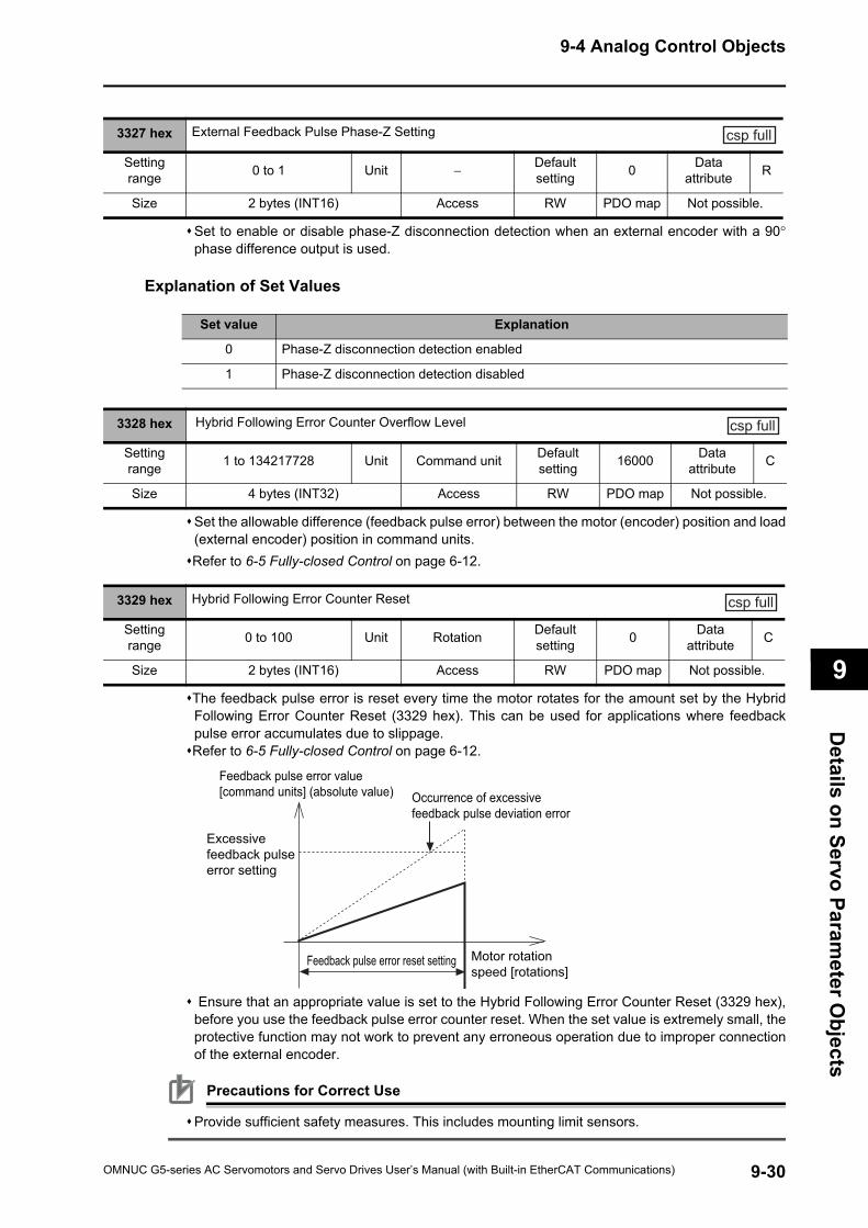
9-4 Analog Control Objects
9
Details on Servo Param
eter Objects
Set to enable or disable phase-Z disconnection detection when an external encoder with a 90°phase difference output is used.
Explanation of Set Values
Set the allowable difference (feedback pulse error) between the motor (encoder) position and load(external encoder) position in command units.Refer to 6-5 Fully-closed Control on page 6-12.
The feedback pulse error is reset every time the motor rotates for the amount set by the HybridFollowing Error Counter Reset (3329 hex). This can be used for applications where feedbackpulse error accumulates due to slippage.Refer to 6-5 Fully-closed Control on page 6-12.
Ensure that an appropriate value is set to the Hybrid Following Error Counter Reset (3329 hex),before you use the feedback pulse error counter reset. When the set value is extremely small, theprotective function may not work to prevent any erroneous operation due to improper connectionof the external encoder.
Precautions for Correct Use
Provide sufficient safety measures. This includes mounting limit sensors.
3327 hex External Feedback Pulse Phase-Z Setting
Setting range 0 to 1 Unit − Default
setting 0 Data attribute R
Size 2 bytes (INT16) Access RW PDO map Not possible.
csp full
Set value Explanation
0 Phase-Z disconnection detection enabled
1 Phase-Z disconnection detection disabled
3328 hex Hybrid Following Error Counter Overflow Level
Setting range 1 to 134217728 Unit Command unit Default
setting 16000 Data attribute C
Size 4 bytes (INT32) Access RW PDO map Not possible.
csp full
3329 hex Hybrid Following Error Counter Reset
Setting range 0 to 100 Unit Rotation Default
setting 0 Data attribute C
Size 2 bytes (INT16) Access RW PDO map Not possible.
csp full
Feedback pulse error value [command units] (absolute value)
Excessivefeedback pulseerror setting
Occurrence of excessivefeedback pulse deviation error
Motor rotationspeed [rotations]
Feedback pulse error reset setting
9-30OMNUC G5-series AC Servomotors and Servo Drives User’s Manual (with Built-in EtherCAT Communications)
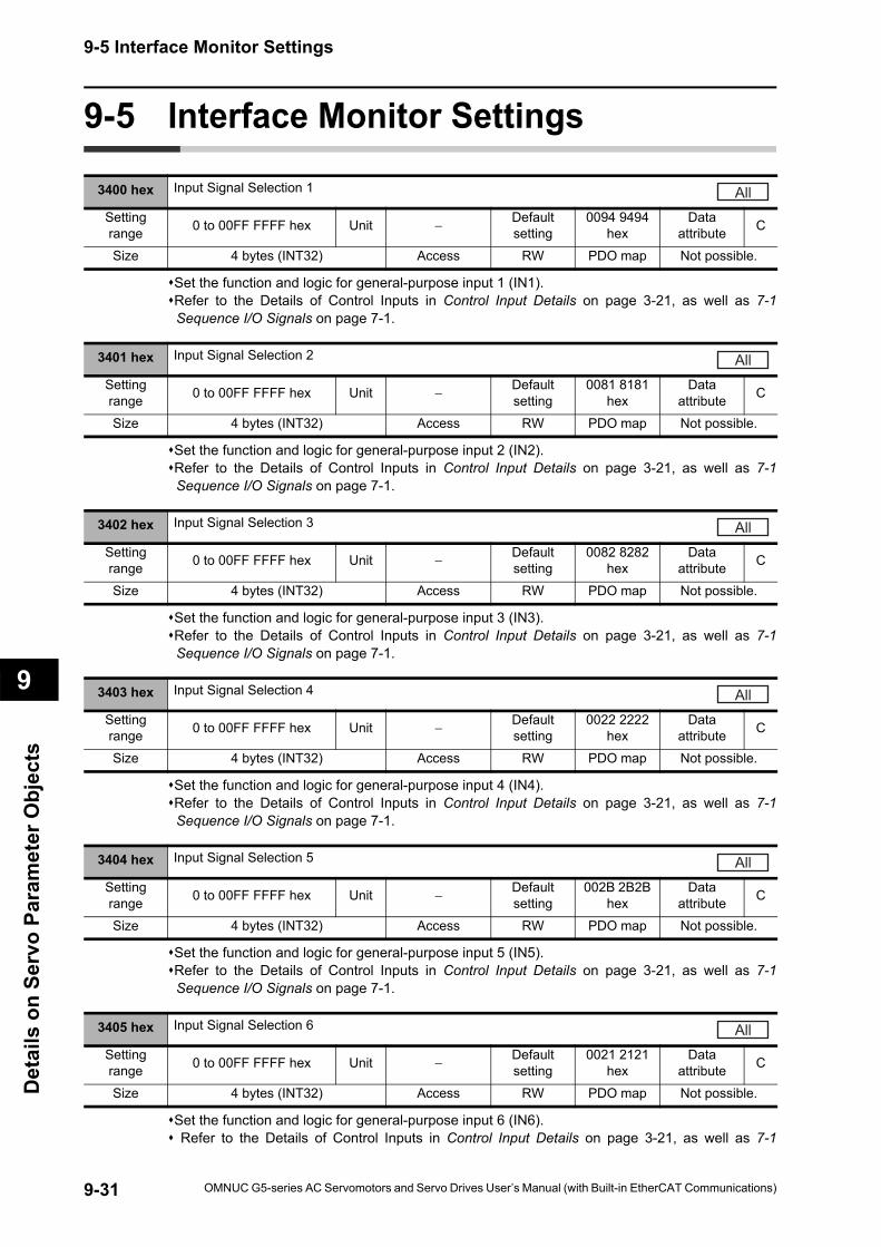
9-5 Interface Monitor Settings
9
Det
ails
on
Serv
o Pa
ram
eter
Obj
ects
9-5 Interface Monitor Settings
Set the function and logic for general-purpose input 1 (IN1).Refer to the Details of Control Inputs in Control Input Details on page 3-21, as well as 7-1Sequence I/O Signals on page 7-1.
Set the function and logic for general-purpose input 2 (IN2).Refer to the Details of Control Inputs in Control Input Details on page 3-21, as well as 7-1Sequence I/O Signals on page 7-1.
Set the function and logic for general-purpose input 3 (IN3).Refer to the Details of Control Inputs in Control Input Details on page 3-21, as well as 7-1Sequence I/O Signals on page 7-1.
Set the function and logic for general-purpose input 4 (IN4).Refer to the Details of Control Inputs in Control Input Details on page 3-21, as well as 7-1Sequence I/O Signals on page 7-1.
Set the function and logic for general-purpose input 5 (IN5).Refer to the Details of Control Inputs in Control Input Details on page 3-21, as well as 7-1Sequence I/O Signals on page 7-1.
Set the function and logic for general-purpose input 6 (IN6). Refer to the Details of Control Inputs in Control Input Details on page 3-21, as well as 7-1
3400 hex Input Signal Selection 1
Setting range 0 to 00FF FFFF hex Unit − Default
setting0094 9494
hexData
attribute C
Size 4 bytes (INT32) Access RW PDO map Not possible.
All
3401 hex Input Signal Selection 2
Setting range 0 to 00FF FFFF hex Unit − Default
setting0081 8181
hexData
attribute C
Size 4 bytes (INT32) Access RW PDO map Not possible.
All
3402 hex Input Signal Selection 3
Setting range 0 to 00FF FFFF hex Unit − Default
setting0082 8282
hexData
attribute C
Size 4 bytes (INT32) Access RW PDO map Not possible.
All
3403 hex Input Signal Selection 4
Setting range 0 to 00FF FFFF hex Unit − Default
setting0022 2222
hexData
attribute C
Size 4 bytes (INT32) Access RW PDO map Not possible.
All
3404 hex Input Signal Selection 5
Setting range 0 to 00FF FFFF hex Unit − Default
setting002B 2B2B
hexData
attribute C
Size 4 bytes (INT32) Access RW PDO map Not possible.
All
3405 hex Input Signal Selection 6
Setting range 0 to 00FF FFFF hex Unit − Default
setting0021 2121
hexData
attribute C
Size 4 bytes (INT32) Access RW PDO map Not possible.
All
9-31 OMNUC G5-series AC Servomotors and Servo Drives User’s Manual (with Built-in EtherCAT Communications)
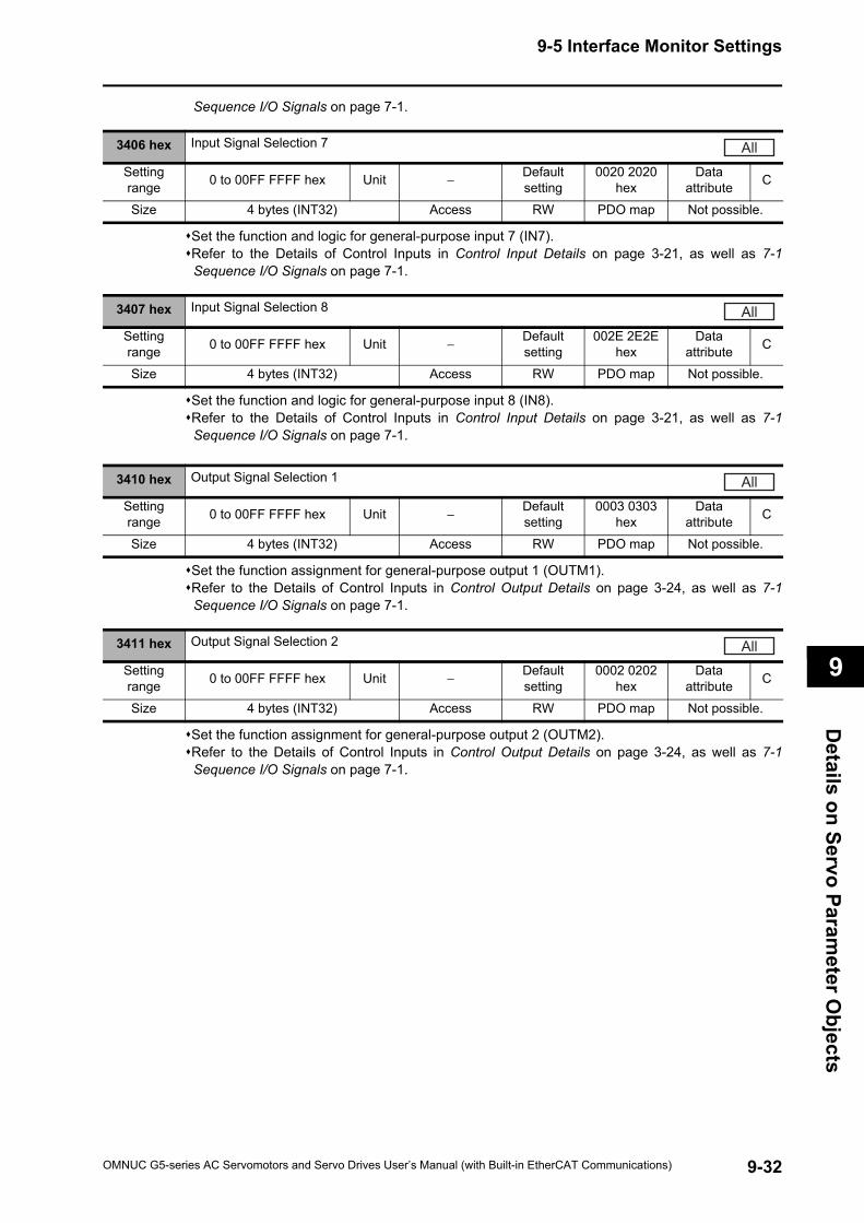
9-5 Interface Monitor Settings
9
Details on Servo Param
eter Objects
Sequence I/O Signals on page 7-1.
Set the function and logic for general-purpose input 7 (IN7).Refer to the Details of Control Inputs in Control Input Details on page 3-21, as well as 7-1Sequence I/O Signals on page 7-1.
Set the function and logic for general-purpose input 8 (IN8).Refer to the Details of Control Inputs in Control Input Details on page 3-21, as well as 7-1Sequence I/O Signals on page 7-1.
Set the function assignment for general-purpose output 1 (OUTM1).Refer to the Details of Control Inputs in Control Output Details on page 3-24, as well as 7-1Sequence I/O Signals on page 7-1.
Set the function assignment for general-purpose output 2 (OUTM2).Refer to the Details of Control Inputs in Control Output Details on page 3-24, as well as 7-1Sequence I/O Signals on page 7-1.
3406 hex Input Signal Selection 7
Setting range 0 to 00FF FFFF hex Unit − Default
setting0020 2020
hexData
attribute C
Size 4 bytes (INT32) Access RW PDO map Not possible.
All
3407 hex Input Signal Selection 8
Setting range 0 to 00FF FFFF hex Unit − Default
setting002E 2E2E
hexData
attribute C
Size 4 bytes (INT32) Access RW PDO map Not possible.
All
3410 hex Output Signal Selection 1
Setting range 0 to 00FF FFFF hex Unit − Default
setting0003 0303
hexData
attribute C
Size 4 bytes (INT32) Access RW PDO map Not possible.
All
3411 hex Output Signal Selection 2
Setting range 0 to 00FF FFFF hex Unit − Default
setting0002 0202
hexData
attribute C
Size 4 bytes (INT32) Access RW PDO map Not possible.
All
9-32OMNUC G5-series AC Servomotors and Servo Drives User’s Manual (with Built-in EtherCAT Communications)
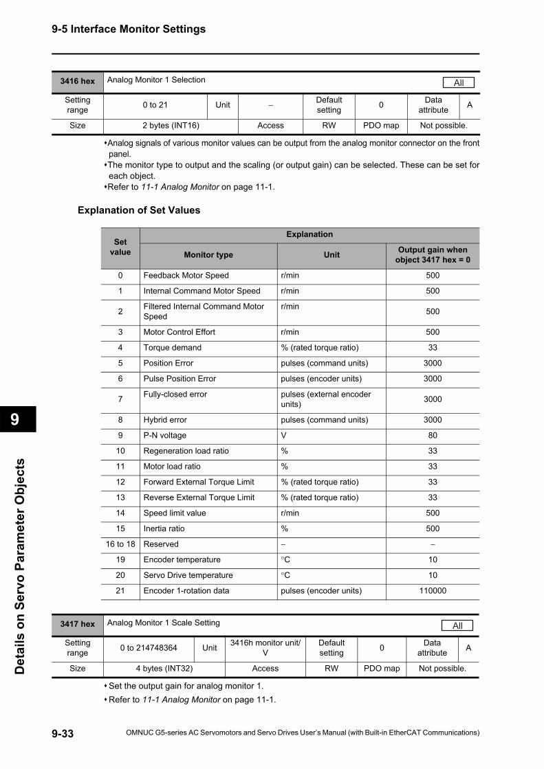
9-5 Interface Monitor Settings
9
Det
ails
on
Serv
o Pa
ram
eter
Obj
ects
Analog signals of various monitor values can be output from the analog monitor connector on the frontpanel.The monitor type to output and the scaling (or output gain) can be selected. These can be set foreach object.Refer to 11-1 Analog Monitor on page 11-1.
Explanation of Set Values
Set the output gain for analog monitor 1.Refer to 11-1 Analog Monitor on page 11-1.
3416 hex Analog Monitor 1 Selection
Setting range 0 to 21 Unit − Default
setting 0 Data attribute A
Size 2 bytes (INT16) Access RW PDO map Not possible.
All
Set value
Explanation
Monitor type Unit Output gain when object 3417 hex = 0
0 Feedback Motor Speed r/min 500
1 Internal Command Motor Speed r/min 500
2 Filtered Internal Command Motor Speed
r/min 500
3 Motor Control Effort r/min 500
4 Torque demand % (rated torque ratio) 33
5 Position Error pulses (command units) 3000
6 Pulse Position Error pulses (encoder units) 3000
7 Fully-closed error pulses (external encoder units) 3000
8 Hybrid error pulses (command units) 3000
9 P-N voltage V 80
10 Regeneration load ratio % 33
11 Motor load ratio % 33
12 Forward External Torque Limit % (rated torque ratio) 33
13 Reverse External Torque Limit % (rated torque ratio) 33
14 Speed limit value r/min 500
15 Inertia ratio % 500
16 to 18 Reserved − −
19 Encoder temperature °C 10
20 Servo Drive temperature °C 10
21 Encoder 1-rotation data pulses (encoder units) 110000
3417 hex Analog Monitor 1 Scale Setting
Setting range 0 to 214748364 Unit 3416h monitor unit/
VDefault setting 0 Data
attribute A
Size 4 bytes (INT32) Access RW PDO map Not possible.
All
9-33 OMNUC G5-series AC Servomotors and Servo Drives User’s Manual (with Built-in EtherCAT Communications)
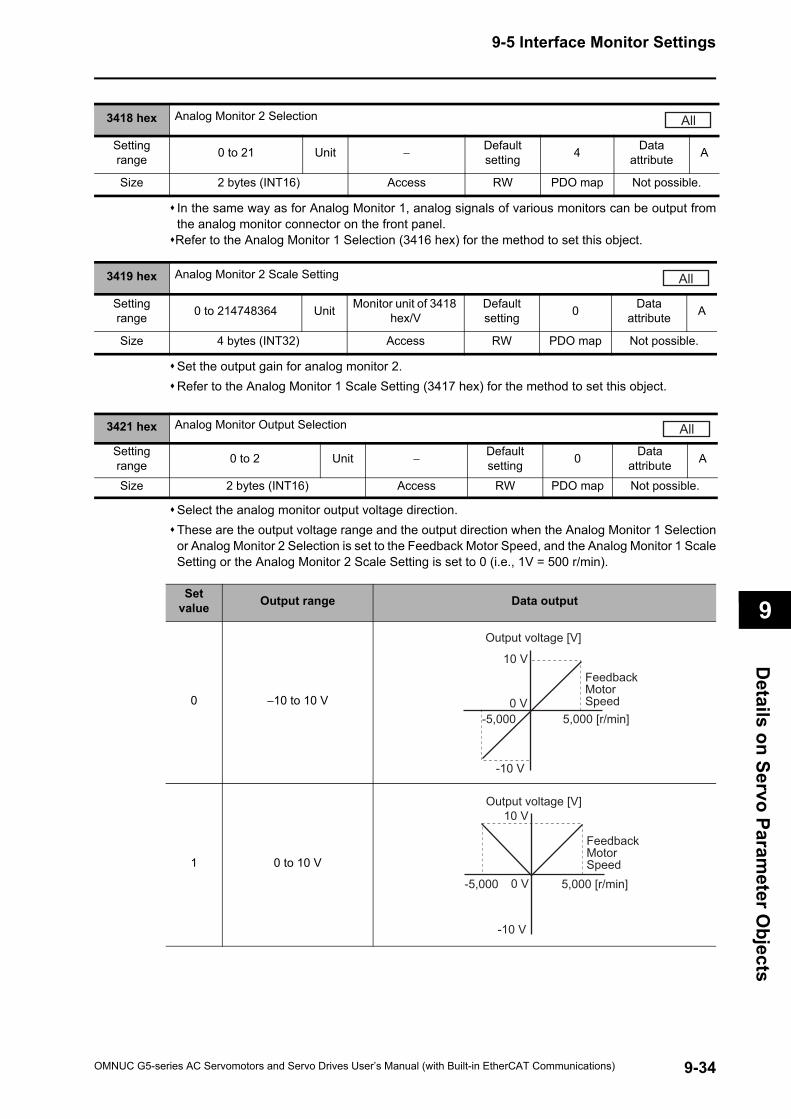
9-5 Interface Monitor Settings
9
Details on Servo Param
eter Objects
In the same way as for Analog Monitor 1, analog signals of various monitors can be output fromthe analog monitor connector on the front panel.Refer to the Analog Monitor 1 Selection (3416 hex) for the method to set this object.
Set the output gain for analog monitor 2.Refer to the Analog Monitor 1 Scale Setting (3417 hex) for the method to set this object.
Select the analog monitor output voltage direction.These are the output voltage range and the output direction when the Analog Monitor 1 Selectionor Analog Monitor 2 Selection is set to the Feedback Motor Speed, and the Analog Monitor 1 ScaleSetting or the Analog Monitor 2 Scale Setting is set to 0 (i.e., 1V = 500 r/min).
3418 hex Analog Monitor 2 Selection
Setting range 0 to 21 Unit − Default
setting 4 Data attribute A
Size 2 bytes (INT16) Access RW PDO map Not possible.
All
3419 hex Analog Monitor 2 Scale Setting
Setting range 0 to 214748364 Unit Monitor unit of 3418
hex/VDefault setting 0 Data
attribute A
Size 4 bytes (INT32) Access RW PDO map Not possible.
All
3421 hex Analog Monitor Output Selection
Setting range 0 to 2 Unit − Default
setting 0 Data attribute A
Size 2 bytes (INT16) Access RW PDO map Not possible.
All
Set value Output range Data output
0 −10 to 10 V
1 0 to 10 V
10 V
-10 V
0 V-5,000 5,000 [r/min]
Feedback Motor Speed
Output voltage [V]
10 V
-10 V
0 V-5,000 5,000 [r/min]
Feedback Motor Speed
Output voltage [V]
9-34OMNUC G5-series AC Servomotors and Servo Drives User’s Manual (with Built-in EtherCAT Communications)
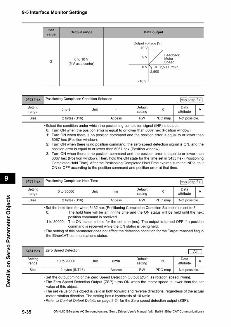
9-5 Interface Monitor Settings
9
Det
ails
on
Serv
o Pa
ram
eter
Obj
ects
Select the condition under which the positioning completion signal (INP) is output.0: Turn ON when the position error is equal to or lower than 6067 hex (Position window).1: Turn ON when there is no position command and the position error is equal to or lower than
6067 hex (Position window).2: Turn ON when there is no position command, the zero speed detection signal is ON, and the
position error is equal to or lower than 6067 hex (Position window).3: Turn ON when there is no position command and the position error is equal to or lower than
6067 hex (Position window). Then, hold the ON state for the time set in 3433 hex (PositioningCompleted Hold Time). After the Positioning Completed Hold Time expires, turn the INP outputON or OFF according to the position command and position error at that time.
Set the hold time for when 3432 hex (Positioning Completion Condition Selection) is set to 3.0: The hold time will be an infinite time and the ON status will be held until the next
position command is received.1 to 30000: The ON status is held for the set time (ms). The output is turned OFF if a position
command is received while the ON status is being held.The setting of this parameter does not affect the detection condition for the Target reached flag inthe EtherCAT communications status.
Set the output timing of the Zero Speed Detection Output (ZSP) as rotation speed [r/min].The Zero Speed Detection Output (ZSP) turns ON when the motor speed is lower than the setvalue of this object.The set value of this object is valid in both forward and reverse directions, regardless of the actualmotor rotation direction. The setting has a hysteresis of 10 r/min.Refer to Control Output Details on page 3-24 for the Zero speed detection output (ZSP).
2 0 to 10 V(5 V as a center)
Set value Output range Data output
10 V
5 V
-10 V
0 V 0-2,500
2,500 [r/min]
Feedback Motor Speed
Output voltage [V]
3432 hex Positioning Completion Condition Selection
Setting range 0 to 3 Unit − Default
setting 0 Data attribute A
Size 2 bytes (U16) Access RW PDO map Not possible.
csp csp full
3433 hex Positioning Completion Hold Time
Setting range 0 to 30000 Unit ms Default
setting 0 Data attribute A
Size 2 bytes (U16) Access RW PDO map Not possible.
csp csp full
3434 hex Zero Speed Detection
Setting range 10 to 20000 Unit r/min Default
setting 50 Data attribute A
Size 2 bytes (INT16) Access RW PDO map Not possible.
All
9-35 OMNUC G5-series AC Servomotors and Servo Drives User’s Manual (with Built-in EtherCAT Communications)
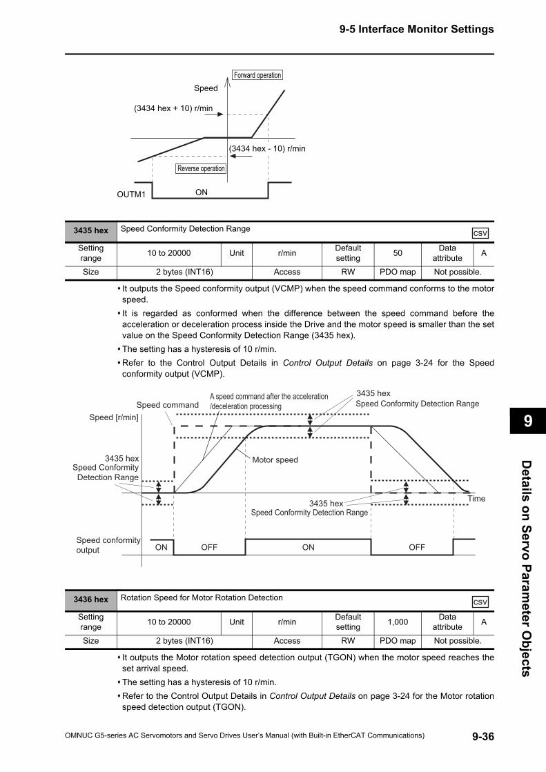
9-5 Interface Monitor Settings
9
Details on Servo Param
eter Objects
It outputs the Speed conformity output (VCMP) when the speed command conforms to the motorspeed.It is regarded as conformed when the difference between the speed command before theacceleration or deceleration process inside the Drive and the motor speed is smaller than the setvalue on the Speed Conformity Detection Range (3435 hex).The setting has a hysteresis of 10 r/min.Refer to the Control Output Details in Control Output Details on page 3-24 for the Speedconformity output (VCMP).
It outputs the Motor rotation speed detection output (TGON) when the motor speed reaches theset arrival speed.The setting has a hysteresis of 10 r/min.Refer to the Control Output Details in Control Output Details on page 3-24 for the Motor rotationspeed detection output (TGON).
Speed
Reverse operation
OUTM1 ON
(3434 hex + 10) r/min
Forward operation
(3434 hex - 10) r/min
3435 hex Speed Conformity Detection Range
Setting range 10 to 20000 Unit r/min Default
setting 50 Data attribute A
Size 2 bytes (INT16) Access RW PDO map Not possible.
csv
Speed [r/min]
A speed command after the acceleration/deceleration processingSpeed command
Motor speed3435 hex
ON ONOFF OFF
3435 hex
Speed ConformityDetection Range
3435 hexSpeed Conformity Detection Range
Speed Conformity Detection Range
Time
Speed conformityoutput
3436 hex Rotation Speed for Motor Rotation Detection
Setting range 10 to 20000 Unit r/min Default
setting 1,000 Data attribute A
Size 2 bytes (INT16) Access RW PDO map Not possible.
csv
9-36OMNUC G5-series AC Servomotors and Servo Drives User’s Manual (with Built-in EtherCAT Communications)
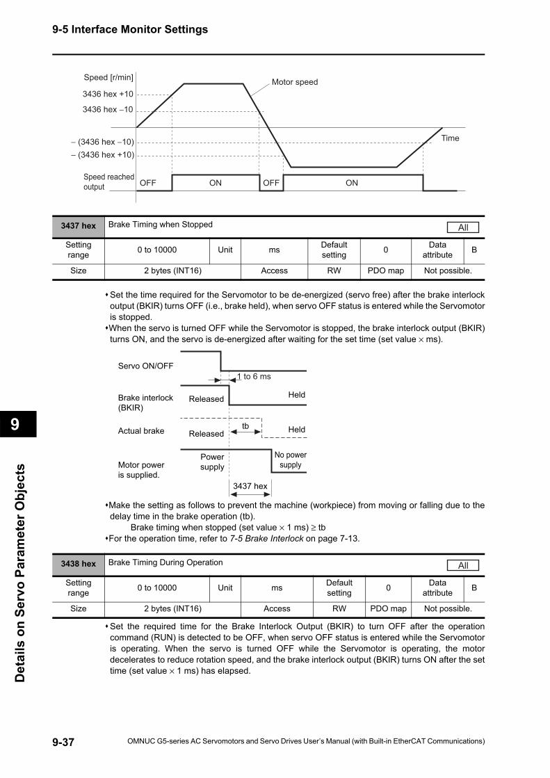
9-5 Interface Monitor Settings
9
Det
ails
on
Serv
o Pa
ram
eter
Obj
ects
Set the time required for the Servomotor to be de-energized (servo free) after the brake interlockoutput (BKIR) turns OFF (i.e., brake held), when servo OFF status is entered while the Servomotoris stopped.When the servo is turned OFF while the Servomotor is stopped, the brake interlock output (BKIR)turns ON, and the servo is de-energized after waiting for the set time (set value × ms).
Make the setting as follows to prevent the machine (workpiece) from moving or falling due to thedelay time in the brake operation (tb).
Brake timing when stopped (set value × 1 ms) ≥ tbFor the operation time, refer to 7-5 Brake Interlock on page 7-13.
Set the required time for the Brake Interlock Output (BKIR) to turn OFF after the operationcommand (RUN) is detected to be OFF, when servo OFF status is entered while the Servomotoris operating. When the servo is turned OFF while the Servomotor is operating, the motordecelerates to reduce rotation speed, and the brake interlock output (BKIR) turns ON after the settime (set value × 1 ms) has elapsed.
Speed [r/min] Motor speed
Time
3436 hex +10
Speed reachedoutput
3436 hex −10
− (3436 hex −10)− (3436 hex +10)
OFF OFFON ON
3437 hex Brake Timing when Stopped
Setting range 0 to 10000 Unit ms Default
setting 0 Data attribute B
Size 2 bytes (INT16) Access RW PDO map Not possible.
All
Servo ON/OFF
Brake interlock(BKIR)
Actual brake
Motor poweris supplied.
Released Held
Released
Powersupply
Held
No powersupply
3437 hex
tb
1 to 6 ms
3438 hex Brake Timing During Operation
Setting range 0 to 10000 Unit ms Default
setting 0 Data attribute B
Size 2 bytes (INT16) Access RW PDO map Not possible.
All
9-37 OMNUC G5-series AC Servomotors and Servo Drives User’s Manual (with Built-in EtherCAT Communications)
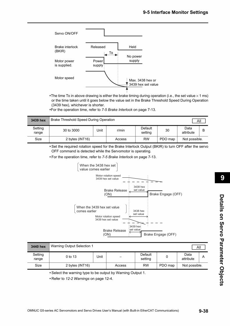
9-5 Interface Monitor Settings
9
Details on Servo Param
eter Objects
The time TB in above drawing is either the brake timing during operation (i.e., the set value × 1 ms)or the time taken until it goes below the value set in the Brake Threshold Speed During Operation(3439 hex), whichever is shorter.For the operation time, refer to 7-5 Brake Interlock on page 7-13.
Set the required rotation speed for the Brake Interlock Output (BKIR) to turn OFF after the servoOFF command is detected while the Servomotor is operating.For the operation time, refer to 7-5 Brake Interlock on page 7-13.
Select the warning type to be output by Warning Output 1.Refer to 12-2 Warnings on page 12-4.
TB
Servo ON/OFF
Brake interlock(BKIR)
Motor speed
Released Held
Motor poweris supplied.
Powersupply
No powersupply
Max. 3438 hex or 3439 hex set value
3439 hex Brake Threshold Speed During Operation
Setting range 30 to 3000 Unit r/min Default
setting 30 Data attribute B
Size 2 bytes (INT16) Access RW PDO map Not possible.
All
Brake Release (ON)
Brake Release (ON) Brake Engage (OFF)
Brake Engage (OFF)
Motor rotation speed3439 hex set value
3438 hex set value
3438 hex set value
Motor rotation speed3439 hex set value
When the 3438 hex set value comes earlier
When the 3439 hex set value comes earlier
3439 hex set value
3440 hex Warning Output Selection 1
Setting range 0 to 13 Unit − Default
setting 0 Data attribute A
Size 2 bytes (INT16) Access RW PDO map Not possible.
All
9-38OMNUC G5-series AC Servomotors and Servo Drives User’s Manual (with Built-in EtherCAT Communications)
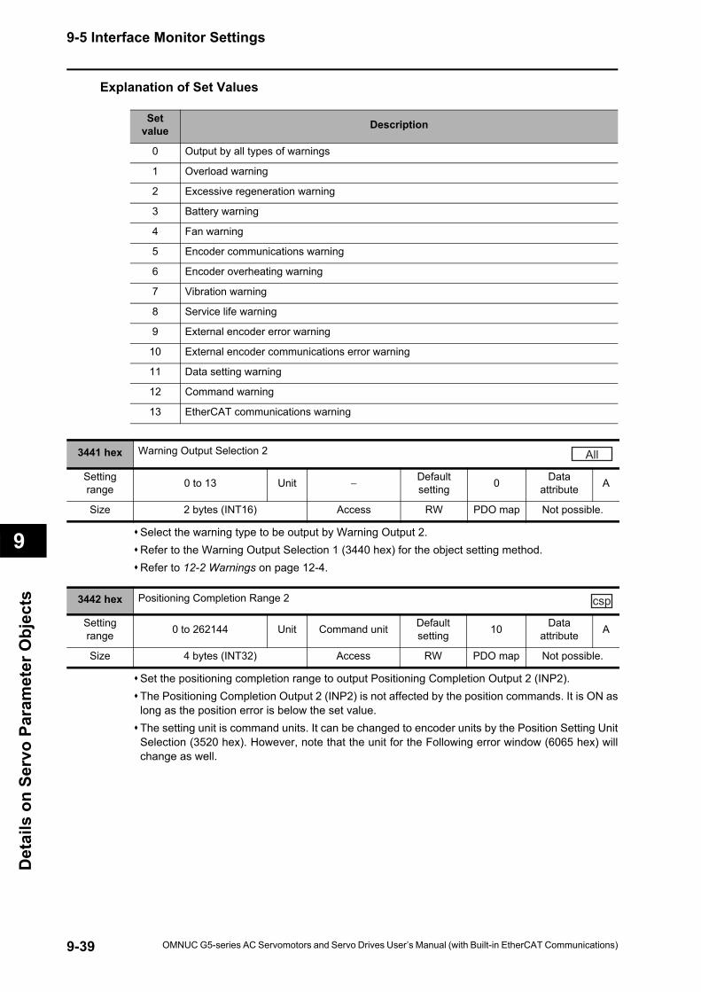
9-5 Interface Monitor Settings
9
Det
ails
on
Serv
o Pa
ram
eter
Obj
ects
Explanation of Set Values
Select the warning type to be output by Warning Output 2.Refer to the Warning Output Selection 1 (3440 hex) for the object setting method.Refer to 12-2 Warnings on page 12-4.
Set the positioning completion range to output Positioning Completion Output 2 (INP2).The Positioning Completion Output 2 (INP2) is not affected by the position commands. It is ON aslong as the position error is below the set value.The setting unit is command units. It can be changed to encoder units by the Position Setting UnitSelection (3520 hex). However, note that the unit for the Following error window (6065 hex) willchange as well.
Set value Description
0 Output by all types of warnings
1 Overload warning
2 Excessive regeneration warning
3 Battery warning
4 Fan warning
5 Encoder communications warning
6 Encoder overheating warning
7 Vibration warning
8 Service life warning
9 External encoder error warning
10 External encoder communications error warning
11 Data setting warning
12 Command warning
13 EtherCAT communications warning
3441 hex Warning Output Selection 2
Setting range 0 to 13 Unit − Default
setting 0 Data attribute A
Size 2 bytes (INT16) Access RW PDO map Not possible.
All
3442 hex Positioning Completion Range 2
Setting range 0 to 262144 Unit Command unit Default
setting 10 Data attribute A
Size 4 bytes (INT32) Access RW PDO map Not possible.
csp
9-39 OMNUC G5-series AC Servomotors and Servo Drives User’s Manual (with Built-in EtherCAT Communications)
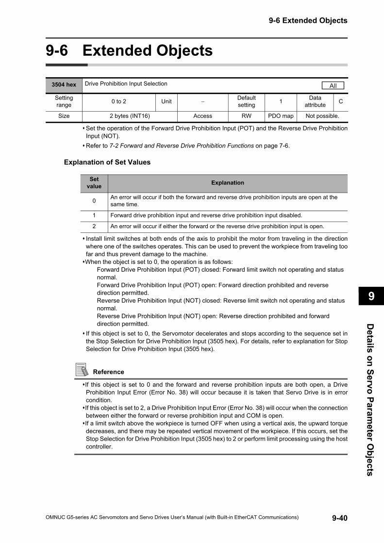
9-6 Extended Objects
9
Details on Servo Param
eter Objects
9-6 Extended Objects
Set the operation of the Forward Drive Prohibition Input (POT) and the Reverse Drive ProhibitionInput (NOT).Refer to 7-2 Forward and Reverse Drive Prohibition Functions on page 7-6.
Explanation of Set Values
Install limit switches at both ends of the axis to prohibit the motor from traveling in the directionwhere one of the switches operates. This can be used to prevent the workpiece from traveling toofar and thus prevent damage to the machine.When the object is set to 0, the operation is as follows:
Forward Drive Prohibition Input (POT) closed: Forward limit switch not operating and status normal.
Forward Drive Prohibition Input (POT) open: Forward direction prohibited and reverse direction permitted.
Reverse Drive Prohibition Input (NOT) closed: Reverse limit switch not operating and status normal.
Reverse Drive Prohibition Input (NOT) open: Reverse direction prohibited and forward direction permitted.
If this object is set to 0, the Servomotor decelerates and stops according to the sequence set inthe Stop Selection for Drive Prohibition Input (3505 hex). For details, refer to explanation for StopSelection for Drive Prohibition Input (3505 hex).
Reference
If this object is set to 0 and the forward and reverse prohibition inputs are both open, a DriveProhibition Input Error (Error No. 38) will occur because it is taken that Servo Drive is in errorcondition. If this object is set to 2, a Drive Prohibition Input Error (Error No. 38) will occur when the connectionbetween either the forward or reverse prohibition input and COM is open.If a limit switch above the workpiece is turned OFF when using a vertical axis, the upward torquedecreases, and there may be repeated vertical movement of the workpiece. If this occurs, set theStop Selection for Drive Prohibition Input (3505 hex) to 2 or perform limit processing using the hostcontroller.
3504 hex Drive Prohibition Input Selection
Setting range 0 to 2 Unit − Default
setting 1 Data attribute C
Size 2 bytes (INT16) Access RW PDO map Not possible.
All
Set value Explanation
0 An error will occur if both the forward and reverse drive prohibition inputs are open at the same time.
1 Forward drive prohibition input and reverse drive prohibition input disabled.
2 An error will occur if either the forward or the reverse drive prohibition input is open.
9-40OMNUC G5-series AC Servomotors and Servo Drives User’s Manual (with Built-in EtherCAT Communications)
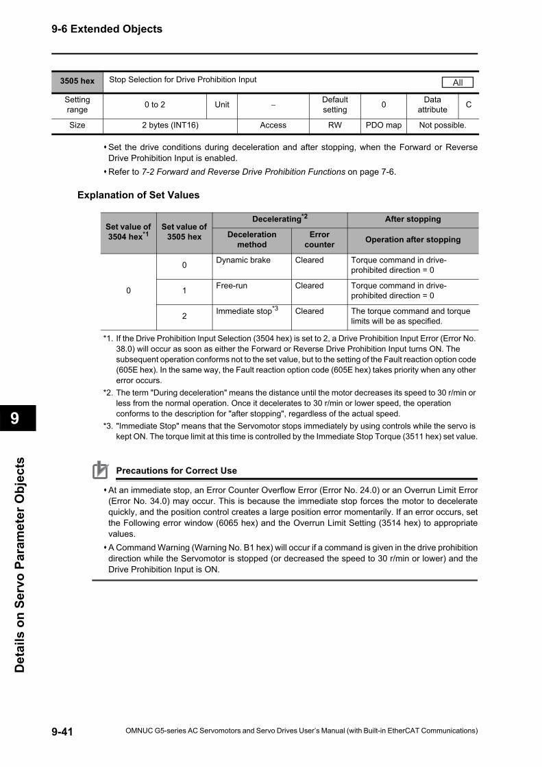
9-6 Extended Objects
9
Det
ails
on
Serv
o Pa
ram
eter
Obj
ects
Set the drive conditions during deceleration and after stopping, when the Forward or ReverseDrive Prohibition Input is enabled.Refer to 7-2 Forward and Reverse Drive Prohibition Functions on page 7-6.
Explanation of Set Values
*1. If the Drive Prohibition Input Selection (3504 hex) is set to 2, a Drive Prohibition Input Error (Error No. 38.0) will occur as soon as either the Forward or Reverse Drive Prohibition Input turns ON. The subsequent operation conforms not to the set value, but to the setting of the Fault reaction option code (605E hex). In the same way, the Fault reaction option code (605E hex) takes priority when any other error occurs.
*2. The term "During deceleration" means the distance until the motor decreases its speed to 30 r/min or less from the normal operation. Once it decelerates to 30 r/min or lower speed, the operation conforms to the description for "after stopping", regardless of the actual speed.
*3. "Immediate Stop" means that the Servomotor stops immediately by using controls while the servo is kept ON. The torque limit at this time is controlled by the Immediate Stop Torque (3511 hex) set value.
Precautions for Correct Use
At an immediate stop, an Error Counter Overflow Error (Error No. 24.0) or an Overrun Limit Error(Error No. 34.0) may occur. This is because the immediate stop forces the motor to deceleratequickly, and the position control creates a large position error momentarily. If an error occurs, setthe Following error window (6065 hex) and the Overrun Limit Setting (3514 hex) to appropriatevalues.A Command Warning (Warning No. B1 hex) will occur if a command is given in the drive prohibitiondirection while the Servomotor is stopped (or decreased the speed to 30 r/min or lower) and theDrive Prohibition Input is ON.
3505 hex Stop Selection for Drive Prohibition Input
Setting range 0 to 2 Unit − Default
setting 0 Data attribute C
Size 2 bytes (INT16) Access RW PDO map Not possible.
All
Set value of 3504 hex*1
Set value of 3505 hex
Decelerating*2 After stopping
Deceleration method
Error counter Operation after stopping
0
0 Dynamic brake Cleared Torque command in drive-prohibited direction = 0
1 Free-run Cleared Torque command in drive-prohibited direction = 0
2 Immediate stop*3 Cleared The torque command and torque limits will be as specified.
9-41 OMNUC G5-series AC Servomotors and Servo Drives User’s Manual (with Built-in EtherCAT Communications)
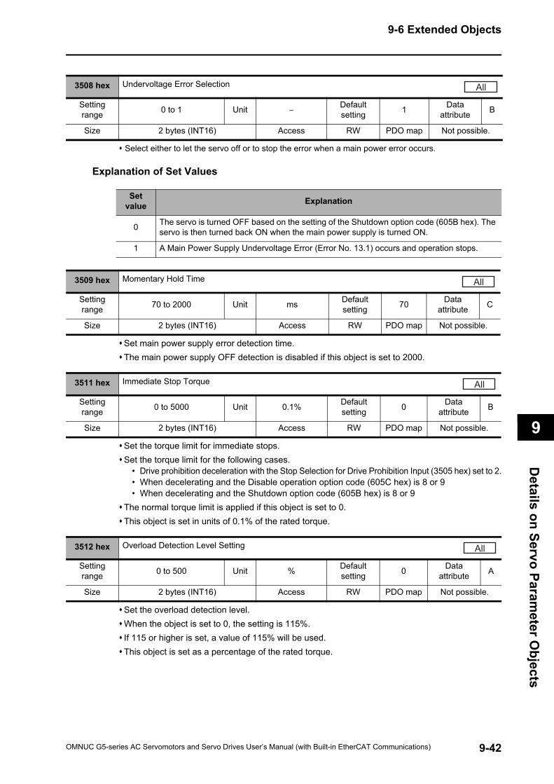
9-6 Extended Objects
9
Details on Servo Param
eter Objects
Select either to let the servo off or to stop the error when a main power error occurs.
Explanation of Set Values
Set main power supply error detection time.The main power supply OFF detection is disabled if this object is set to 2000.
Set the torque limit for immediate stops.Set the torque limit for the following cases.
• Drive prohibition deceleration with the Stop Selection for Drive Prohibition Input (3505 hex) set to 2.• When decelerating and the Disable operation option code (605C hex) is 8 or 9• When decelerating and the Shutdown option code (605B hex) is 8 or 9
The normal torque limit is applied if this object is set to 0.This object is set in units of 0.1% of the rated torque.
Set the overload detection level.When the object is set to 0, the setting is 115%.If 115 or higher is set, a value of 115% will be used.This object is set as a percentage of the rated torque.
3508 hex Undervoltage Error Selection
Setting range 0 to 1 Unit − Default
setting 1 Data attribute B
Size 2 bytes (INT16) Access RW PDO map Not possible.
All
Set value Explanation
0 The servo is turned OFF based on the setting of the Shutdown option code (605B hex). The servo is then turned back ON when the main power supply is turned ON.
1 A Main Power Supply Undervoltage Error (Error No. 13.1) occurs and operation stops.
3509 hex Momentary Hold Time
Setting range 70 to 2000 Unit ms Default
setting 70 Data attribute C
Size 2 bytes (INT16) Access RW PDO map Not possible.
3511 hex Immediate Stop Torque
Setting range 0 to 5000 Unit 0.1% Default
setting 0 Data attribute B
Size 2 bytes (INT16) Access RW PDO map Not possible.
All
All
3512 hex Overload Detection Level Setting
Setting range 0 to 500 Unit % Default
setting 0 Data attribute A
Size 2 bytes (INT16) Access RW PDO map Not possible.
All
9-42OMNUC G5-series AC Servomotors and Servo Drives User’s Manual (with Built-in EtherCAT Communications)
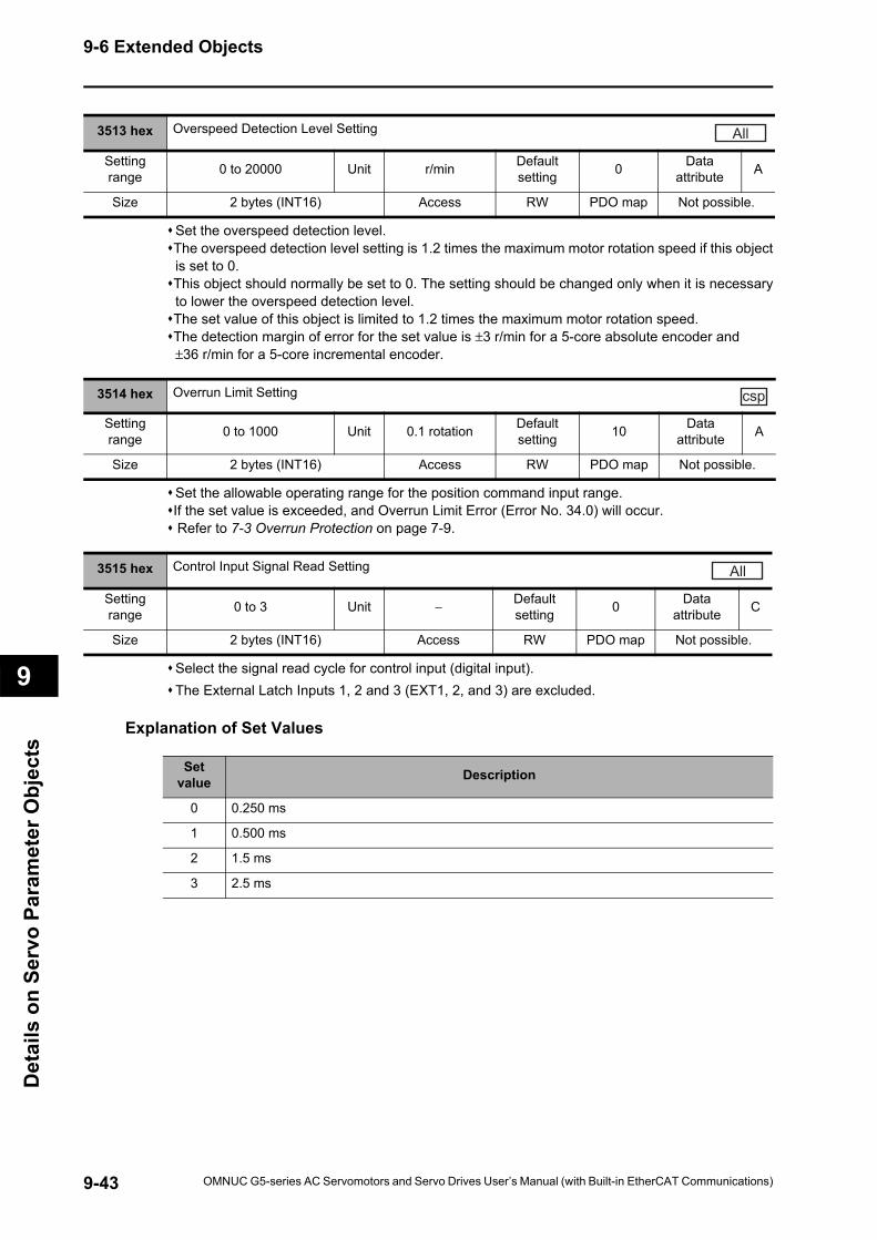
9-6 Extended Objects
9
Det
ails
on
Serv
o Pa
ram
eter
Obj
ects
Set the overspeed detection level.The overspeed detection level setting is 1.2 times the maximum motor rotation speed if this objectis set to 0.This object should normally be set to 0. The setting should be changed only when it is necessaryto lower the overspeed detection level.The set value of this object is limited to 1.2 times the maximum motor rotation speed.The detection margin of error for the set value is ±3 r/min for a 5-core absolute encoder and ±36 r/min for a 5-core incremental encoder.
Set the allowable operating range for the position command input range.If the set value is exceeded, and Overrun Limit Error (Error No. 34.0) will occur. Refer to 7-3 Overrun Protection on page 7-9.
Select the signal read cycle for control input (digital input).The External Latch Inputs 1, 2 and 3 (EXT1, 2, and 3) are excluded.
Explanation of Set Values
3513 hex Overspeed Detection Level Setting
Setting range 0 to 20000 Unit r/min Default
setting 0 Data attribute A
Size 2 bytes (INT16) Access RW PDO map Not possible.
All
3514 hex Overrun Limit Setting
Setting range 0 to 1000 Unit 0.1 rotation Default
setting 10 Data attribute A
Size 2 bytes (INT16) Access RW PDO map Not possible.
csp
3515 hex Control Input Signal Read Setting
Setting range 0 to 3 Unit − Default
setting 0 Data attribute C
Size 2 bytes (INT16) Access RW PDO map Not possible.
All
Set value Description
0 0.250 ms
1 0.500 ms
2 1.5 ms
3 2.5 ms
9-43 OMNUC G5-series AC Servomotors and Servo Drives User’s Manual (with Built-in EtherCAT Communications)
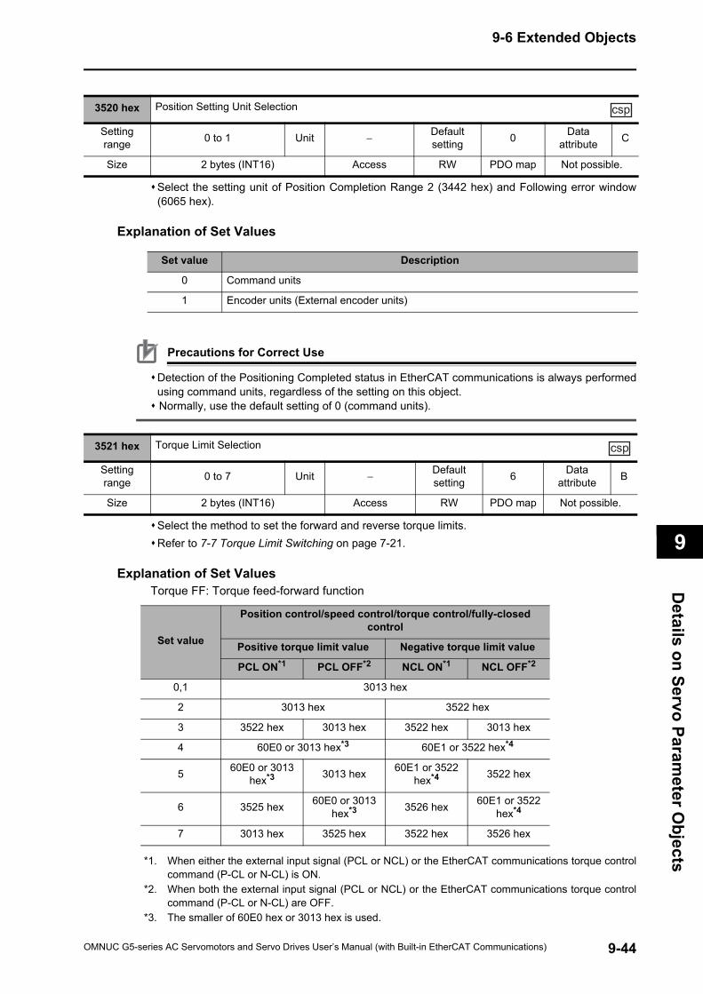
9-6 Extended Objects
9
Details on Servo Param
eter Objects
Select the setting unit of Position Completion Range 2 (3442 hex) and Following error window(6065 hex).
Explanation of Set Values
Precautions for Correct Use
Detection of the Positioning Completed status in EtherCAT communications is always performedusing command units, regardless of the setting on this object.Normally, use the default setting of 0 (command units).
Select the method to set the forward and reverse torque limits.Refer to 7-7 Torque Limit Switching on page 7-21.
Explanation of Set ValuesTorque FF: Torque feed-forward function
*1. When either the external input signal (PCL or NCL) or the EtherCAT communications torque controlcommand (P-CL or N-CL) is ON.
*2. When both the external input signal (PCL or NCL) or the EtherCAT communications torque controlcommand (P-CL or N-CL) are OFF.
*3. The smaller of 60E0 hex or 3013 hex is used.
3520 hex Position Setting Unit Selection
Setting range 0 to 1 Unit − Default
setting 0 Data attribute C
Size 2 bytes (INT16) Access RW PDO map Not possible.
csp
Set value Description
0 Command units
1 Encoder units (External encoder units)
3521 hex Torque Limit Selection
Setting range 0 to 7 Unit − Default
setting 6 Data attribute B
Size 2 bytes (INT16) Access RW PDO map Not possible.
csp
Set value
Position control/speed control/torque control/fully-closed control
Positive torque limit value Negative torque limit value
PCL ON*1 PCL OFF*2 NCL ON*1 NCL OFF*2
0,1 3013 hex
2 3013 hex 3522 hex
3 3522 hex 3013 hex 3522 hex 3013 hex
4 60E0 or 3013 hex*3 60E1 or 3522 hex*4
5 60E0 or 3013 hex*3 3013 hex 60E1 or 3522
hex*4 3522 hex
6 3525 hex 60E0 or 3013 hex*3 3526 hex 60E1 or 3522
hex*4
7 3013 hex 3525 hex 3522 hex 3526 hex
9-44OMNUC G5-series AC Servomotors and Servo Drives User’s Manual (with Built-in EtherCAT Communications)
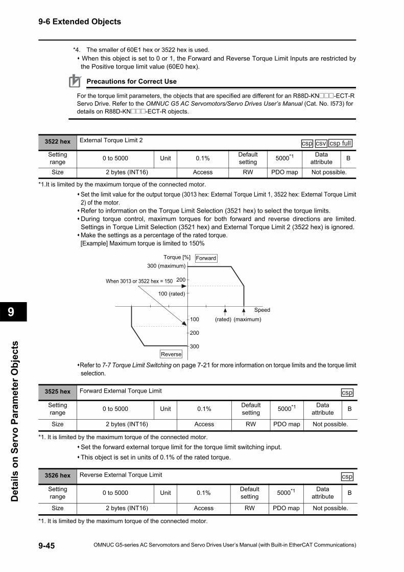
9-6 Extended Objects
9
Det
ails
on
Serv
o Pa
ram
eter
Obj
ects
*4. The smaller of 60E1 hex or 3522 hex is used. When this object is set to 0 or 1, the Forward and Reverse Torque Limit Inputs are restricted bythe Positive torque limit value (60E0 hex).
Precautions for Correct Use
For the torque limit parameters, the objects that are specified are different for an R88D-KN@@@-ECT-R Servo Drive. Refer to the OMNUC G5 AC Servomotors/Servo Drives User’s Manual (Cat. No. I573) for details on R88D-KN@@@-ECT-R objects.
*1.It is limited by the maximum torque of the connected motor.Set the limit value for the output torque (3013 hex: External Torque Limit 1, 3522 hex: External Torque Limit2) of the motor.Refer to information on the Torque Limit Selection (3521 hex) to select the torque limits.During torque control, maximum torques for both forward and reverse directions are limited.Settings in Torque Limit Selection (3521 hex) and External Torque Limit 2 (3522 hex) is ignored.Make the settings as a percentage of the rated torque.
[Example] Maximum torque is limited to 150%
Refer to 7-7 Torque Limit Switching on page 7-21 for more information on torque limits and the torque limitselection.
*1. It is limited by the maximum torque of the connected motor.Set the forward external torque limit for the torque limit switching input.This object is set in units of 0.1% of the rated torque.
*1. It is limited by the maximum torque of the connected motor.
3522 hex External Torque Limit 2
Setting range 0 to 5000 Unit 0.1% Default
setting 5000*1 Data attribute B
Size 2 bytes (INT16) Access RW PDO map Not possible.
csp csp fullcsv
Speed
200
100 (rated)
(rated)100
200
300
Torque [%]300 (maximum)
(maximum)
Reverse
Forward
When 3013 or 3522 hex = 150
3525 hex Forward External Torque Limit
Setting range 0 to 5000 Unit 0.1% Default
setting 5000*1 Data attribute B
Size 2 bytes (INT16) Access RW PDO map Not possible.
csp
3526 hex Reverse External Torque Limit
Setting range 0 to 5000 Unit 0.1% Default
setting 5000*1 Data attribute B
Size 2 bytes (INT16) Access RW PDO map Not possible.
csp
9-45 OMNUC G5-series AC Servomotors and Servo Drives User’s Manual (with Built-in EtherCAT Communications)
9-6 Extended Objects
9
Details on Servo Param
eter Objects
Set the reverse external torque limit for the torque limit switching input.This object is set in units of 0.1% of the rated torque.
9-46OMNUC G5-series AC Servomotors and Servo Drives User’s Manual (with Built-in EtherCAT Communications)
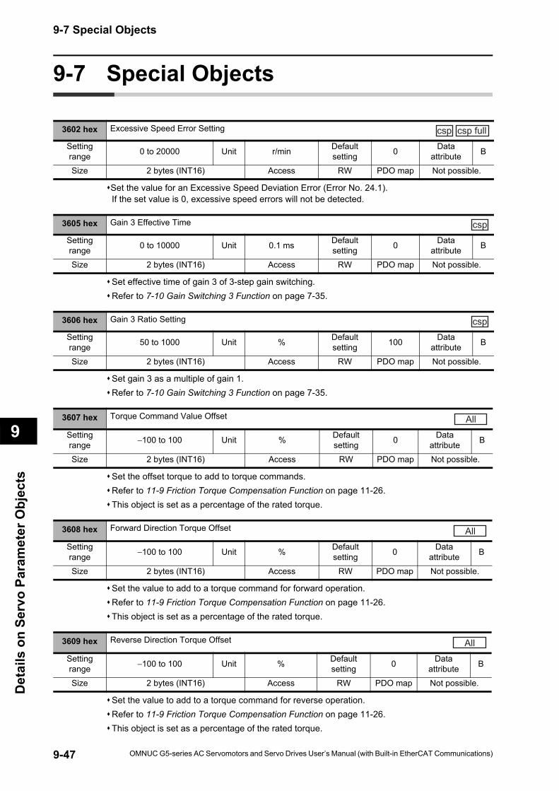
9-7 Special Objects
9
Det
ails
on
Serv
o Pa
ram
eter
Obj
ects
9-7 Special Objects
Set the value for an Excessive Speed Deviation Error (Error No. 24.1).If the set value is 0, excessive speed errors will not be detected.
Set effective time of gain 3 of 3-step gain switching.Refer to 7-10 Gain Switching 3 Function on page 7-35.
Set gain 3 as a multiple of gain 1.Refer to 7-10 Gain Switching 3 Function on page 7-35.
Set the offset torque to add to torque commands.Refer to 11-9 Friction Torque Compensation Function on page 11-26.This object is set as a percentage of the rated torque.
Set the value to add to a torque command for forward operation.Refer to 11-9 Friction Torque Compensation Function on page 11-26.This object is set as a percentage of the rated torque.
Set the value to add to a torque command for reverse operation.Refer to 11-9 Friction Torque Compensation Function on page 11-26.This object is set as a percentage of the rated torque.
3602 hex Excessive Speed Error Setting
Setting range 0 to 20000 Unit r/min Default
setting 0 Data attribute B
Size 2 bytes (INT16) Access RW PDO map Not possible.
csp csp full
3605 hex Gain 3 Effective Time
Setting range 0 to 10000 Unit 0.1 ms Default
setting 0 Data attribute B
Size 2 bytes (INT16) Access RW PDO map Not possible.
csp
3606 hex Gain 3 Ratio Setting
Setting range 50 to 1000 Unit % Default
setting 100 Data attribute B
Size 2 bytes (INT16) Access RW PDO map Not possible.
csp
3607 hex Torque Command Value Offset
Setting range −100 to 100 Unit % Default
setting 0 Data attribute B
Size 2 bytes (INT16) Access RW PDO map Not possible.
All
3608 hex Forward Direction Torque Offset
Setting range −100 to 100 Unit % Default
setting 0 Data attribute B
Size 2 bytes (INT16) Access RW PDO map Not possible.
3609 hex Reverse Direction Torque Offset
Setting range −100 to 100 Unit % Default
setting 0 Data attribute B
Size 2 bytes (INT16) Access RW PDO map Not possible.
All
All
9-47 OMNUC G5-series AC Servomotors and Servo Drives User’s Manual (with Built-in EtherCAT Communications)
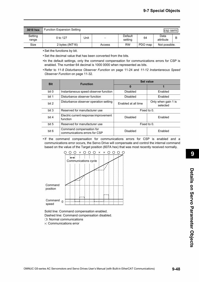
9-7 Special Objects
9
Details on Servo Param
eter Objects
Set the functions by bit.Set the decimal value that has been converted from the bits.In the default settings, only the command compensation for communications errors for CSP isenabled. The number 64 decimal is 1000 0000 when represented as bits.Refer to 11-8 Disturbance Observer Function on page 11-24 and 11-12 Instantaneous SpeedObserver Function on page 11-32.
If the command compensation for communications errors for CSP is enabled and acommunications error occurs, the Servo Drive will compensate and control the internal commandbased on the value of the Target position (607A hex) that was most recently received normally.
Solid line: Command compensation enabled.Dashed line: Command compensation disabled.: Normal communications×: Communications error
3610 hex Function Expansion Setting
Setting range 0 to 127 Unit − Default
setting 64 Data attribute B
Size 2 bytes (INT16) Access RW PDO map Not possible.
csp semi
Bit FunctionSet value
0 1bit 0 Instantaneous speed observer function Disabled Enabled
bit 1 Disturbance observer function Disabled Enabled
bit 2 Disturbance observer operation setting Enabled at all time Only when gain 1 is selected
bit 3 Reserved for manufacturer use Fixed to 0.
bit 4 Electric current response improvement function Disabled Enabled
bit 5 Reserved for manufacturer use Fixed to 0.
bit 6 Command compensation for communications errors for CSP Disabled Enabled
Command speed
Command position
Communications cycle
0
9-48OMNUC G5-series AC Servomotors and Servo Drives User’s Manual (with Built-in EtherCAT Communications)
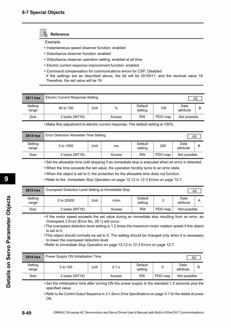
9-7 Special Objects
9
Det
ails
on
Serv
o Pa
ram
eter
Obj
ects
Reference
Example Instantaneous speed observer function: enabled Disturbance observer function: enabled Disturbance observer operation setting: enabled at all time Electric current response improvement function: enabled Command compensation for communications errors for CSP: DisabledIf the settings are as described above, the bit will be 0010011, and the decimal value 19.Therefore, the set value will be 19.
Make fine adjustment to electric current response. The default setting is 100%.
Set the allowable time until stopping if an immediate stop is executed when an error is detected.When the time exceeds the set value, the operation forcibly turns to an error state.When the object is set to 0, the protection for the allowable time does not function.Refer to the Immediate Stop Operation on page 12-12 in 12-3 Errors on page 12-7.
If the motor speed exceeds the set value during an immediate stop resulting from an error, anOverspeed 2 Error (Error No. 26.1) will occur.The overspeed detection level setting is 1.2 times the maximum motor rotation speed if this objectis set to 0.This object should normally be set to 0. The setting should be changed only when it is necessaryto lower the overspeed detection level.Refer to Immediate Stop Operation on page 12-12 in 12-3 Errors on page 12-7.
Set the initialization time after turning ON the power supply to the standard 1.5 seconds plus thespecified value.Refer to the Control Output Sequence in 3-1 Servo Drive Specifications on page 3-1 for the details at powerON.
3611 hex Electric Current Response Setting
Setting range 50 to 100 Unit % Default
setting 100 Data attribute B
Size 2 bytes (INT16) Access RW PDO map Not possible.
All
3614 hex Error Detection Allowable Time Setting
Setting range 0 to 1000 Unit ms Default
setting 200 Data attribute B
Size 2 bytes (INT16) Access RW PDO map Not possible.
All
3615 hex Overspeed Detection Level Setting at Immediate Stop
Setting range 0 to 20000 Unit r/min Default
setting 0 Data attribute A
Size 2 bytes (INT16) Access RW PDO map Not possible.
All
3618 hex Power Supply ON Initialization Time
Setting range 0 to 100 Unit 0.1 s Default
setting 0 Data attribute R
Size 2 bytes (INT16) Access RW PDO map Not possible.
All
9-49 OMNUC G5-series AC Servomotors and Servo Drives User’s Manual (with Built-in EtherCAT Communications)
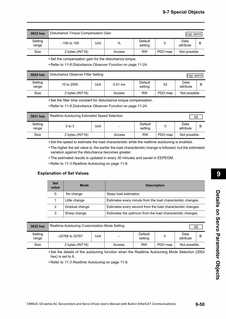
9-7 Special Objects
9
Details on Servo Param
eter Objects
Set the compensation gain for the disturbance torque.Refer to 11-8 Disturbance Observer Function on page 11-24.
Set the filter time constant for disturbance torque compensation.Refer to 11-8 Disturbance Observer Function on page 11-24.
Set the speed to estimate the load characteristic while the realtime autotuning is enabled.The higher the set value is, the earlier the load characteristic change is followed, but the estimatedvariation against the disturbance becomes greater.The estimated results is updated in every 30 minutes and saved in EEPEOM.Refer to 11-3 Realtime Autotuning on page 11-6.
Explanation of Set Values
Set the details of the autotuning function when the Realtime Autotuning Mode Selection (3002hex) is set to 6.Refer to 11-3 Realtime Autotuning on page 11-6.
3623 hex Disturbance Torque Compensation Gain
Setting range −100 to 100 Unit % Default
setting 0 Data attribute B
Size 2 bytes (INT16) Access RW PDO map Not possible.
csp semi
3624 hex Disturbance Observer Filter Setting
Setting range 10 to 2500 Unit 0.01 ms Default
setting 53 Data attribute B
Size 2 bytes (INT16) Access RW PDO map Not possible.
csp semi
3631 hex Realtime Autotuning Estimated Speed Selection
Setting range 0 to 3 Unit − Default
setting 0 Data attribute B
Size 2 bytes (INT16) Access RW PDO map Not possible.
All
Set value Mode Description
0 No change Stops load estimation.
1 Little change Estimates every minute from the load characteristic changes.
2 Gradual change Estimates every second from the load characteristic changes.
3 Sharp change Estimates the optimum from the load characteristic changes.
3632 hex Realtime Autotuning Customization Mode Setting
Setting range −32768 to 32767 Unit − Default
setting 0 Data attribute B
Size 2 bytes (INT16) Access RW PDO map Not possible.
All
9-50OMNUC G5-series AC Servomotors and Servo Drives User’s Manual (with Built-in EtherCAT Communications)
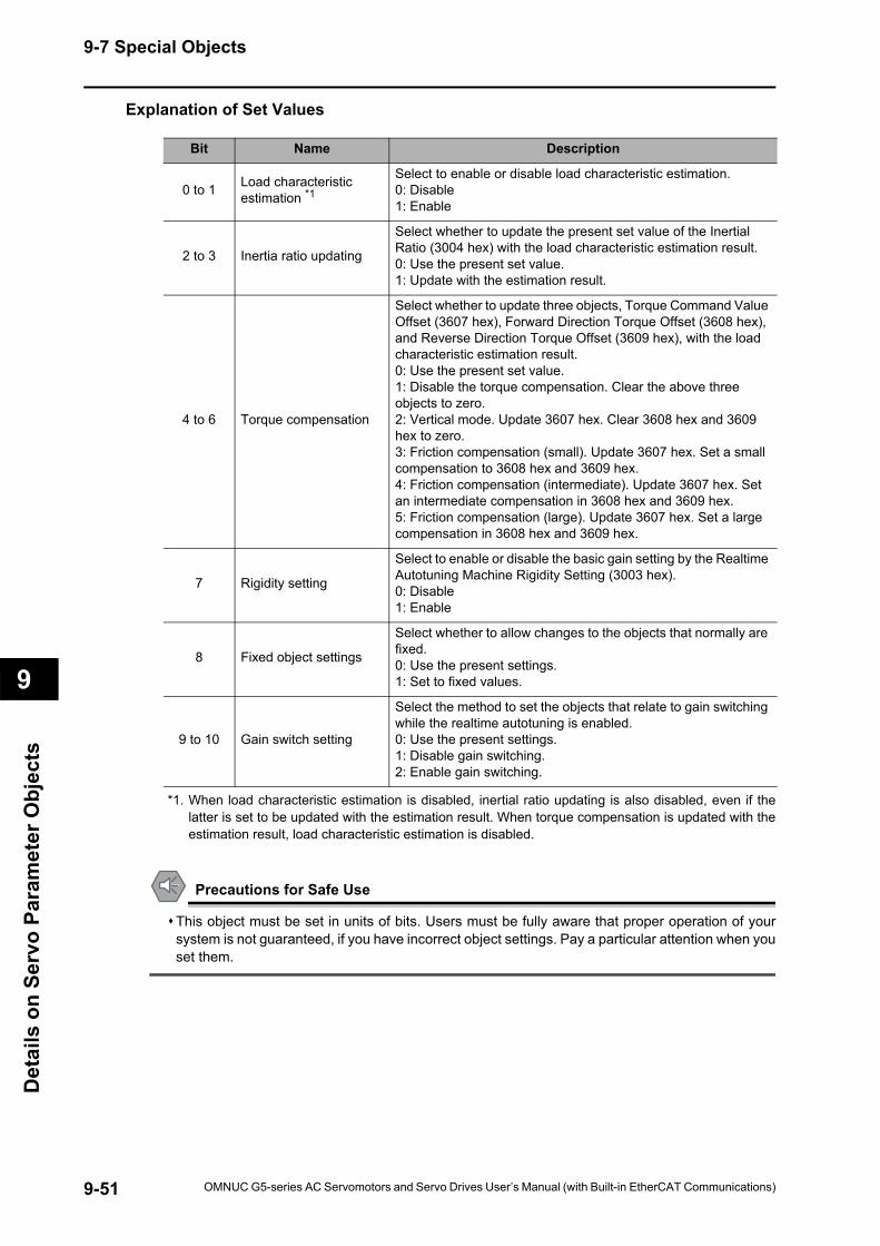
9-7 Special Objects
9
Det
ails
on
Serv
o Pa
ram
eter
Obj
ects
Explanation of Set Values
*1. When load characteristic estimation is disabled, inertial ratio updating is also disabled, even if thelatter is set to be updated with the estimation result. When torque compensation is updated with theestimation result, load characteristic estimation is disabled.
Precautions for Safe Use
This object must be set in units of bits. Users must be fully aware that proper operation of yoursystem is not guaranteed, if you have incorrect object settings. Pay a particular attention when youset them.
Bit Name Description
0 to 1 Load characteristic estimation *1
Select to enable or disable load characteristic estimation.0: Disable1: Enable
2 to 3 Inertia ratio updating
Select whether to update the present set value of the Inertial Ratio (3004 hex) with the load characteristic estimation result.0: Use the present set value.1: Update with the estimation result.
4 to 6 Torque compensation
Select whether to update three objects, Torque Command Value Offset (3607 hex), Forward Direction Torque Offset (3608 hex), and Reverse Direction Torque Offset (3609 hex), with the load characteristic estimation result.0: Use the present set value.1: Disable the torque compensation. Clear the above three objects to zero.2: Vertical mode. Update 3607 hex. Clear 3608 hex and 3609 hex to zero.3: Friction compensation (small). Update 3607 hex. Set a small compensation to 3608 hex and 3609 hex.4: Friction compensation (intermediate). Update 3607 hex. Set an intermediate compensation in 3608 hex and 3609 hex.5: Friction compensation (large). Update 3607 hex. Set a large compensation in 3608 hex and 3609 hex.
7 Rigidity setting
Select to enable or disable the basic gain setting by the Realtime Autotuning Machine Rigidity Setting (3003 hex).0: Disable1: Enable
8 Fixed object settings
Select whether to allow changes to the objects that normally are fixed.0: Use the present settings.1: Set to fixed values.
9 to 10 Gain switch setting
Select the method to set the objects that relate to gain switching while the realtime autotuning is enabled.0: Use the present settings.1: Disable gain switching.2: Enable gain switching.
9-51 OMNUC G5-series AC Servomotors and Servo Drives User’s Manual (with Built-in EtherCAT Communications)
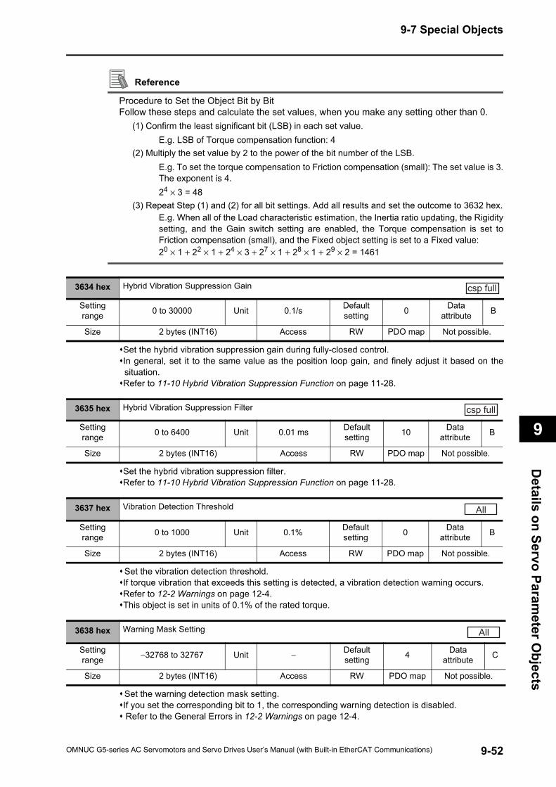
9-7 Special Objects
9
Details on Servo Param
eter Objects
Reference
Procedure to Set the Object Bit by BitFollow these steps and calculate the set values, when you make any setting other than 0.
(1) Confirm the least significant bit (LSB) in each set value.E.g. LSB of Torque compensation function: 4
(2) Multiply the set value by 2 to the power of the bit number of the LSB. E.g. To set the torque compensation to Friction compensation (small): The set value is 3.The exponent is 4.24 × 3 = 48
(3) Repeat Step (1) and (2) for all bit settings. Add all results and set the outcome to 3632 hex.E.g. When all of the Load characteristic estimation, the Inertia ratio updating, the Rigiditysetting, and the Gain switch setting are enabled, the Torque compensation is set toFriction compensation (small), and the Fixed object setting is set to a Fixed value:20 × 1 + 22 × 1 + 24 × 3 + 27 × 1 + 28 × 1 + 29 × 2 = 1461
Set the hybrid vibration suppression gain during fully-closed control.In general, set it to the same value as the position loop gain, and finely adjust it based on thesituation.Refer to 11-10 Hybrid Vibration Suppression Function on page 11-28.
Set the hybrid vibration suppression filter.Refer to 11-10 Hybrid Vibration Suppression Function on page 11-28.
Set the vibration detection threshold.If torque vibration that exceeds this setting is detected, a vibration detection warning occurs.Refer to 12-2 Warnings on page 12-4.This object is set in units of 0.1% of the rated torque.
Set the warning detection mask setting.If you set the corresponding bit to 1, the corresponding warning detection is disabled. Refer to the General Errors in 12-2 Warnings on page 12-4.
3634 hex Hybrid Vibration Suppression Gain
Setting range 0 to 30000 Unit 0.1/s Default
setting 0 Data attribute B
Size 2 bytes (INT16) Access RW PDO map Not possible.
csp full
3635 hex Hybrid Vibration Suppression Filter
Setting range 0 to 6400 Unit 0.01 ms Default
setting 10 Data attribute B
Size 2 bytes (INT16) Access RW PDO map Not possible.
3637 hex Vibration Detection Threshold
Setting range 0 to 1000 Unit 0.1% Default
setting 0 Data attribute B
Size 2 bytes (INT16) Access RW PDO map Not possible.
csp full
All
3638 hex Warning Mask Setting
Setting range −32768 to 32767 Unit − Default
setting 4 Data attribute C
Size 2 bytes (INT16) Access RW PDO map Not possible.
All
9-52OMNUC G5-series AC Servomotors and Servo Drives User’s Manual (with Built-in EtherCAT Communications)
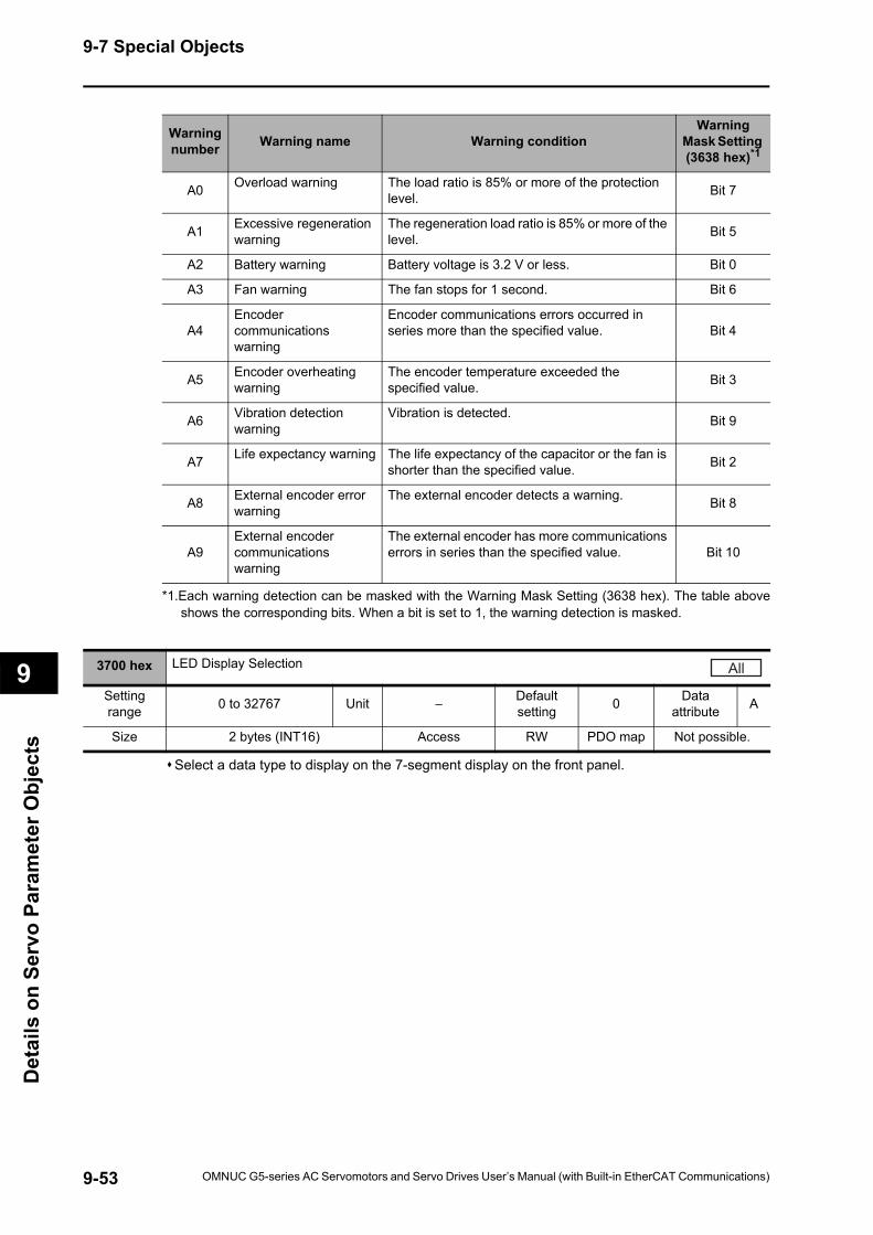
9-7 Special Objects
9
Det
ails
on
Serv
o Pa
ram
eter
Obj
ects
Select a data type to display on the 7-segment display on the front panel.
Warning number Warning name Warning condition
Warning Mask Setting (3638 hex)*1
A0 Overload warning The load ratio is 85% or more of the protection level. Bit 7
A1 Excessive regeneration warning
The regeneration load ratio is 85% or more of the level. Bit 5
A2 Battery warning Battery voltage is 3.2 V or less. Bit 0
A3 Fan warning The fan stops for 1 second. Bit 6
A4Encoder communications warning
Encoder communications errors occurred in series more than the specified value. Bit 4
A5 Encoder overheating warning
The encoder temperature exceeded the specified value. Bit 3
A6 Vibration detection warning
Vibration is detected. Bit 9
A7 Life expectancy warning The life expectancy of the capacitor or the fan is shorter than the specified value. Bit 2
A8 External encoder error warning
The external encoder detects a warning. Bit 8
A9External encoder communications warning
The external encoder has more communications errors in series than the specified value. Bit 10
*1.Each warning detection can be masked with the Warning Mask Setting (3638 hex). The table aboveshows the corresponding bits. When a bit is set to 1, the warning detection is masked.
3700 hex LED Display Selection
Setting range 0 to 32767 Unit − Default
setting 0 Data attribute A
Size 2 bytes (INT16) Access RW PDO map Not possible.
All
9-53 OMNUC G5-series AC Servomotors and Servo Drives User’s Manual (with Built-in EtherCAT Communications)
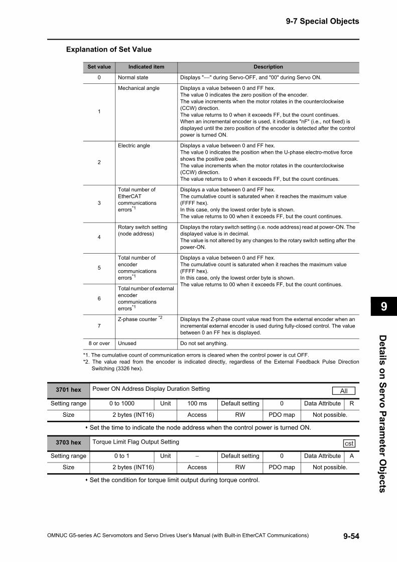
9-7 Special Objects
9
Details on Servo Param
eter Objects
Explanation of Set Value
Set the time to indicate the node address when the control power is turned ON.
Set the condition for torque limit output during torque control.
Set value Indicated item Description
0 Normal state Displays "−−" during Servo-OFF, and "00" during Servo ON.
1
Mechanical angle Displays a value between 0 and FF hex.The value 0 indicates the zero position of the encoder.The value increments when the motor rotates in the counterclockwise (CCW) direction.The value returns to 0 when it exceeds FF, but the count continues.When an incremental encoder is used, it indicates "nF" (i.e., not fixed) is displayed until the zero position of the encoder is detected after the control power is turned ON.
2
Electric angle Displays a value between 0 and FF hex.The value 0 indicates the position when the U-phase electro-motive force shows the positive peak.The value increments when the motor rotates in the counterclockwise (CCW) direction.The value returns to 0 when it exceeds FF, but the count continues.
3
Total number of EtherCAT communications errors*1
*1. The cumulative count of communication errors is cleared when the control power is cut OFF.
Displays a value between 0 and FF hex.The cumulative count is saturated when it reaches the maximum value (FFFF hex).In this case, only the lowest order byte is shown.The value returns to 00 when it exceeds FF, but the count continues.
4
Rotary switch setting (node address)
Displays the rotary switch setting (i.e. node address) read at power-ON. The displayed value is in decimal.The value is not altered by any changes to the rotary switch setting after the power-ON.
5
Total number of encoder communications errors*1
Displays a value between 0 and FF hex.The cumulative count is saturated when it reaches the maximum value (FFFF hex).In this case, only the lowest order byte is shown.The value returns to 00 when it exceeds FF, but the count continues.
6
Total number of external encoder communications errors*1
7Z-phase counter *2
*2. The value read from the encoder is indicated directly, regardless of the External Feedback Pulse DirectionSwitching (3326 hex).
Displays the Z-phase count value read from the external encoder when an incremental external encoder is used during fully-closed control. The value between 0 an FF hex is displayed.
8 or over Unused Do not set anything.
3701 hex Power ON Address Display Duration Setting
Setting range 0 to 1000 Unit 100 ms Default setting 0 Data Attribute R
Size 2 bytes (INT16) Access RW PDO map Not possible.
All
3703 hex Torque Limit Flag Output Setting
Setting range 0 to 1 Unit − Default setting 0 Data Attribute A
Size 2 bytes (INT16) Access RW PDO map Not possible.
cst
9-54OMNUC G5-series AC Servomotors and Servo Drives User’s Manual (with Built-in EtherCAT Communications)
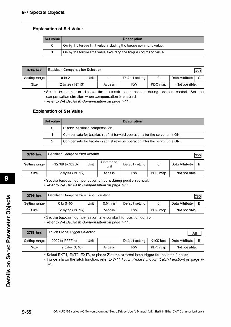
9-7 Special Objects
9
Det
ails
on
Serv
o Pa
ram
eter
Obj
ects
Explanation of Set Value
Select to enable or disable the backlash compensation during position control. Set thecompensation direction when compensation is enabled.Refer to 7-4 Backlash Compensation on page 7-11.
Explanation of Set Value
Set the backlash compensation amount during position control.Refer to 7-4 Backlash Compensation on page 7-11.
Set the backlash compensation time constant for position control.Refer to 7-4 Backlash Compensation on page 7-11.
Select EXT1, EXT2, EXT3, or phase Z at the external latch trigger for the latch function. For details on the latch function, refer to 7-11 Touch Probe Function (Latch Function) on page 7-37.
Set value Description
0 On by the torque limit value including the torque command value.
1 On by the torque limit value excluding the torque command value.
3704 hex Backlash Compensation Selection
Setting range 0 to 2 Unit − Default setting 0 Data Attribute C
Size 2 bytes (INT16) Access RW PDO map Not possible.
csp
Set value Description
0 Disable backlash compensation.
1 Compensate for backlash at first forward operation after the servo turns ON.
2 Compensate for backlash at first reverse operation after the servo turns ON.
3705 hex Backlash Compensation Amount
Setting range −32768 to 32767 Unit Command unit Default setting 0 Data Attribute B
Size 2 bytes (INT16) Access RW PDO map Not possible.
csp
3706 hex Backlash Compensation Time Constant
Setting range 0 to 6400 Unit 0.01 ms Default setting 0 Data Attribute B
Size 2 bytes (INT16) Access RW PDO map Not possible.
csp
3758 hex Touch Probe Trigger Selection
Setting range 0000 to FFFF hex Unit − Default setting 0100 hex Data Attribute B
Size 2 bytes (U16) Access RW PDO map Not possible.
All
9-55 OMNUC G5-series AC Servomotors and Servo Drives User’s Manual (with Built-in EtherCAT Communications)
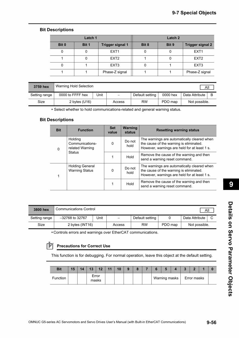
9-7 Special Objects
9
Details on Servo Param
eter Objects
Bit Descriptions
Select whether to hold communications-related and general warning status.
Bit Descriptions
Controls errors and warnings over EtherCAT communications.
Precautions for Correct Use
This function is for debugging. For normal operation, leave this object at the default setting.
Latch 1 Latch 2
Bit 0 Bit 1 Trigger signal 1 Bit 8 Bit 9 Trigger signal 2
0 0 EXT1 0 0 EXT1
1 0 EXT2 1 0 EXT2
0 1 EXT3 0 1 EXT3
1 1 Phase-Z signal 1 1 Phase-Z signal
3759 hex Warning Hold Selection
Setting range 0000 to FFFF hex Unit − Default setting 0000 hex Data Attribute B
Size 2 bytes (U16) Access RW PDO map Not possible.
All
Bit Function Set value
Warning status Resetting warning status
0
Holding Communications-related Warning Status
0 Do not hold
The warnings are automatically cleared when the cause of the warning is eliminated. However, warnings are held for at least 1 s.
1 Hold Remove the cause of the warning and then send a warning reset command.
1
Holding General Warning Status 0 Do not
hold
The warnings are automatically cleared when the cause of the warning is eliminated. However, warnings are held for at least 1 s.
1 Hold Remove the cause of the warning and then send a warning reset command.
3800 hex Communications Control
Setting range −32768 to 32767 Unit − Default setting 0 Data Attribute C
Size 2 bytes (INT16) Access RW PDO map Not possible.
All
Bit 15 14 13 12 11 10 9 8 7 6 5 4 3 2 1 0
Function Error masks Warning masks Error masks
9-56OMNUC G5-series AC Servomotors and Servo Drives User’s Manual (with Built-in EtherCAT Communications)
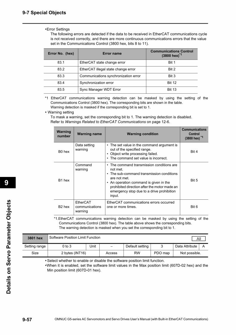
9-7 Special Objects
9
Det
ails
on
Serv
o Pa
ram
eter
Obj
ects
Error SettingsThe following errors are detected if the data to be received in EtherCAT communications cycle is not received correctly, and there are more continuous communications errors that the value set in the Communications Control (3800 hex, bits 8 to 11).
*1 EtherCAT communications warning detection can be masked by using the setting of theCommunications Control (3800 hex). The corresponding bits are shown in the table. Warning detection is masked if the corresponding bit is set to 1.
Warning settingTo mask a warning, set the corresponding bit to 1. The warning detection is disabled.Refer to Warnings Related to EtherCAT Communications on page 12-6.
Select whether to enable or disable the software position limit function.When it is enabled, set the software limit values in the Max position limit (607D-02 hex) and theMin position limit (607D-01 hex).
Error No. (hex) Error name Communications Control (3800 hex)*1
83.1 EtherCAT state change error Bit 1
83.2 EtherCAT illegal state change error Bit 2
83.3 Communications synchronization error Bit 3
83.4 Synchronization error Bit 12
83.5 Sync Manager WDT Error Bit 13
Warning number Warning name Warning condition
Communications Control
(3800 hex) *1
B0 hex
Data setting warning
• The set value in the command argument is out of the specified range.
• Object write processing failed. • The command set value is incorrect.
Bit 4
B1 hex
Command warning
• The command transmission conditions are not met.
• The sub-command transmission conditions are not met.
• An operation command is given in the prohibited direction after the motor made an emergency stop due to a drive prohibition input.
Bit 5
B2 hexEtherCAT communications warning
EtherCAT communications errors occurred one or more times. Bit 6
*1.EtherCAT communications warning detection can be masked by using the setting of theCommunications Control (3800 hex). The table above shows the corresponding bits. The warning detection is masked when you set the corresponding bit to 1.
3801 hex Software Position Limit Function
Setting range 0 to 3 Unit − Default setting 3 Data Attribute A
Size 2 bytes (INT16) Access RW PDO map Not possible.
All
9-57 OMNUC G5-series AC Servomotors and Servo Drives User’s Manual (with Built-in EtherCAT Communications)
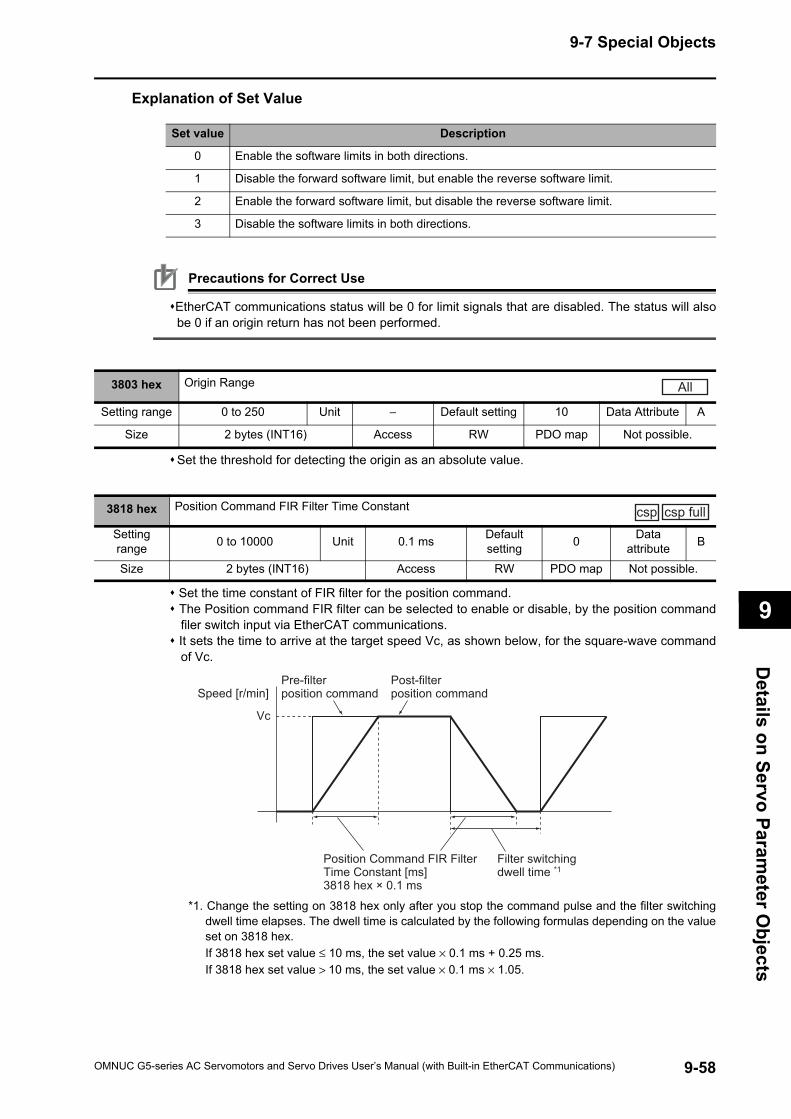
9-7 Special Objects
9
Details on Servo Param
eter Objects
Explanation of Set Value
Precautions for Correct Use
EtherCAT communications status will be 0 for limit signals that are disabled. The status will alsobe 0 if an origin return has not been performed.
Set the threshold for detecting the origin as an absolute value.
Set the time constant of FIR filter for the position command. The Position command FIR filter can be selected to enable or disable, by the position commandfiler switch input via EtherCAT communications.
It sets the time to arrive at the target speed Vc, as shown below, for the square-wave commandof Vc.
*1. Change the setting on 3818 hex only after you stop the command pulse and the filter switchingdwell time elapses. The dwell time is calculated by the following formulas depending on the valueset on 3818 hex.If 3818 hex set value ≤ 10 ms, the set value × 0.1 ms + 0.25 ms.If 3818 hex set value > 10 ms, the set value × 0.1 ms × 1.05.
Set value Description
0 Enable the software limits in both directions.
1 Disable the forward software limit, but enable the reverse software limit.
2 Enable the forward software limit, but disable the reverse software limit.
3 Disable the software limits in both directions.
3803 hex Origin Range
Setting range 0 to 250 Unit − Default setting 10 Data Attribute A
Size 2 bytes (INT16) Access RW PDO map Not possible.
All
3818 hex Position Command FIR Filter Time Constant
Setting range 0 to 10000 Unit 0.1 ms Default
setting 0 Data attribute B
Size 2 bytes (INT16) Access RW PDO map Not possible.
csp csp full
Speed [r/min]
Vc
Pre-filterposition command
Post-filterposition command
Position Command FIR FilterTime Constant [ms]3818 hex × 0.1 ms
Filter switchingdwell time *1
9-58OMNUC G5-series AC Servomotors and Servo Drives User’s Manual (with Built-in EtherCAT Communications)
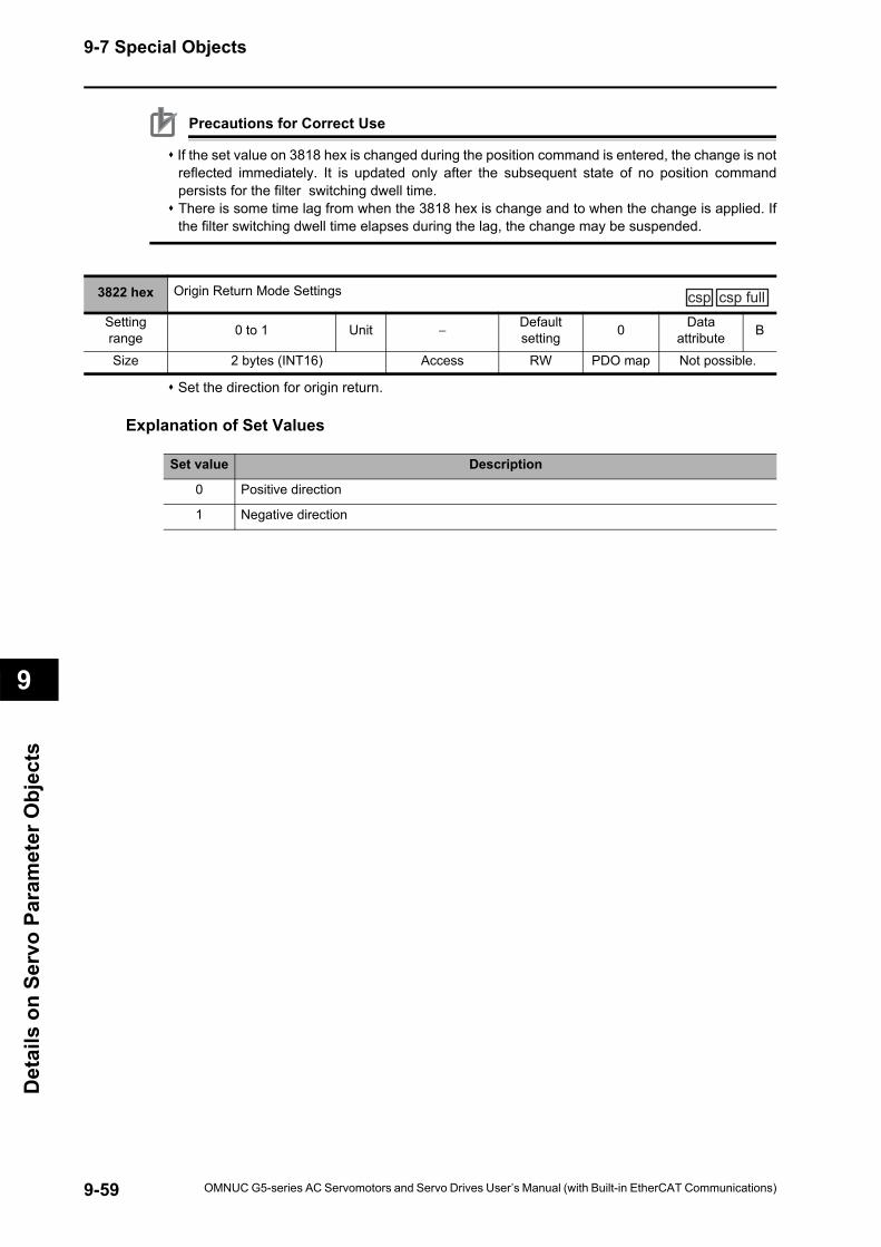
9-7 Special Objects
9
Det
ails
on
Serv
o Pa
ram
eter
Obj
ects
Precautions for Correct Use
If the set value on 3818 hex is changed during the position command is entered, the change is notreflected immediately. It is updated only after the subsequent state of no position commandpersists for the filter switching dwell time.
There is some time lag from when the 3818 hex is change and to when the change is applied. Ifthe filter switching dwell time elapses during the lag, the change may be suspended.
Set the direction for origin return.
Explanation of Set Values
3822 hex Origin Return Mode Settings
Setting range 0 to 1 Unit − Default
setting 0 Data attribute B
Size 2 bytes (INT16) Access RW PDO map Not possible.
csp csp full
Set value Description
0 Positive direction
1 Negative direction
9-59 OMNUC G5-series AC Servomotors and Servo Drives User’s Manual (with Built-in EtherCAT Communications)
10
OperationThis chapter explains the operating procedures and how to operate in each mode.
10-1 Operational Procedure ...............................................10-110-2 Preparing for Operation .............................................10-210-3 Trial Operation ............................................................10-7
OMNUC G5-series AC Servomotors and Servo Drives User’s Manual (with Built-in EtherCAT Communications)
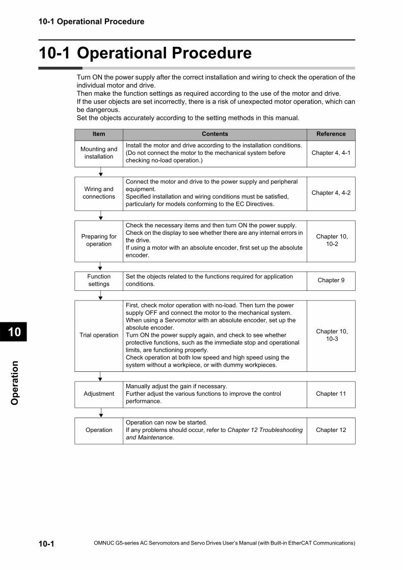
10-1 Operational Procedure
10
Ope
ratio
n
10-1 Operational ProcedureTurn ON the power supply after the correct installation and wiring to check the operation of theindividual motor and drive.Then make the function settings as required according to the use of the motor and drive.If the user objects are set incorrectly, there is a risk of unexpected motor operation, which canbe dangerous.Set the objects accurately according to the setting methods in this manual.
Item Contents Reference
Mounting and installation
Install the motor and drive according to the installation conditions. (Do not connect the motor to the mechanical system before checking no-load operation.)
Chapter 4, 4-1
Wiring and connections
Connect the motor and drive to the power supply and peripheral equipment.Specified installation and wiring conditions must be satisfied, particularly for models conforming to the EC Directives.
Chapter 4, 4-2
Preparing for operation
Check the necessary items and then turn ON the power supply.Check on the display to see whether there are any internal errors in the drive.If using a motor with an absolute encoder, first set up the absolute encoder.
Chapter 10, 10-2
Function settings
Set the objects related to the functions required for application conditions. Chapter 9
Trial operation
First, check motor operation with no-load. Then turn the power supply OFF and connect the motor to the mechanical system.When using a Servomotor with an absolute encoder, set up the absolute encoder. Turn ON the power supply again, and check to see whether protective functions, such as the immediate stop and operational limits, are functioning properly.Check operation at both low speed and high speed using the system without a workpiece, or with dummy workpieces.
Chapter 10, 10-3
AdjustmentManually adjust the gain if necessary.Further adjust the various functions to improve the control performance.
Chapter 11
OperationOperation can now be started.If any problems should occur, refer to Chapter 12 Troubleshooting and Maintenance.
Chapter 12
10-1 OMNUC G5-series AC Servomotors and Servo Drives User’s Manual (with Built-in EtherCAT Communications)
10-2 Preparing for Operation
10
Operation
10-2 Preparing for OperationThis section explains the procedure to prepare the mechanical system for operation followinginstallation and wiring of the motor and drive. It explains items to check both before and afterturning ON the power supply. It also explains the setup procedure required if using a motor withan absolute encoder.
Items to Check Before Turning ON the Power Supply
Checking Power Supply VoltageCheck to be sure that the power supply voltage is within the ranges shown below.R88D-KNA5L-ECT/-KN01L-ECT/-KN02L-ECT/-KN04L-ECT (Single-phase 100-VAC input) Main circuit power supply: Single-phase 100 to 120 VAC (85 to 132) 50/60 HzControl circuit power supply: Single-phase 100 to 120 VAC (85 to 132) 50/60 Hz
R88D-KN01H-ECT/-KN02H-ECT/-KN04H-ECT/-KN08H-ECT/-KN10H-ECT/-KN15H-ECT(Single-phase or single-phase/3-phase 200-VAC input)Main circuit power supply: Single-phase or single-phase/3-phase 200 to 240 VAC (170 to 264) 50/60 Hz Control circuit power supply: Single-phase 200 to 240 VAC (170 to 264) 50/60 Hz
R88D-KN20H-ECT/-KN30H-ECT/-KN50H-ECT/-KN75H-ECT/-KN150H-ECT(3-phase 200 VAC input)Main circuit power supply: 3-phase 200 to 230 VAC (170 to 253) 50/60 Hz Control circuit power supply: Single-phase 200 to 230 VAC (170 to 253) 50/60 Hz
R88D-KN06F-ECT/-KN10F-ECT/-KN15F-ECT/-KN20F-ECT/-KN30F-ECT/-KN50F-ECT/-KN75F-ECT/-KN150F-ECT (3-phase 400 VAC input)Main circuit power supply: 3-phase 380 to 480 VAC (323 to 528) 50/60 Hz Control circuit power supply: 24 VDC ± 15%
Checking Terminal Block WiringThe main circuit power supply inputs (L1/L3 or L1/L2/L3) must be properly connected to theterminal block. The control circuit power supply inputs (L1C/L2C) must be properly connected to the terminalblock. The motor's red (U), write (V), and blue (W) power lines and the green/yellow ( ) must beproperly connected to the terminal block.
Checking the MotorThere should be no load on the motor. (Do not connect the mechanical system.)The motor side power lines and the power cables must be securely connected.
Checking the Encoder WiringThe encoder cable must be securely connected to the encoder connector (CN2) at the drive.The encoder cable must be securely connected to the encoder connector at the motor.
10-2OMNUC G5-series AC Servomotors and Servo Drives User’s Manual (with Built-in EtherCAT Communications)
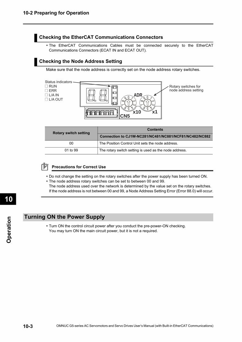
10-2 Preparing for Operation
10
Ope
ratio
n
Checking the EtherCAT Communications ConnectorsThe EtherCAT Communications Cables must be connected securely to the EtherCATCommunications Connectors (ECAT IN and ECAT OUT).
Checking the Node Address SettingMake sure that the node address is correctly set on the node address rotary switches.
Precautions for Correct Use
Do not change the setting on the rotary switches after the power supply has been turned ON. The node address rotary switches can be set to between 00 and 99.The node address used over the network is determined by the value set on the rotary switches.If the node address is not between 00 and 99, a Node Address Setting Error (Error 88.0) will occur.
Turning ON the Power SupplyTurn ON the control circuit power after you conduct the pre-power-ON checking.You may turn ON the main circuit power, but it is not a required.
CN5
ADR
x10 x1
Status indicators@ RUN@ ERR@ L/A IN@ L/A OUT
Rotary switches for node address setting
Rotary switch settingContents
Connection to CJ1W-NC281/NC481/NC881/NCF81/NC482/NC882
00 The Position Control Unit sets the node address.
01 to 99 The rotary switch setting is used as the node address.
10-3 OMNUC G5-series AC Servomotors and Servo Drives User’s Manual (with Built-in EtherCAT Communications)
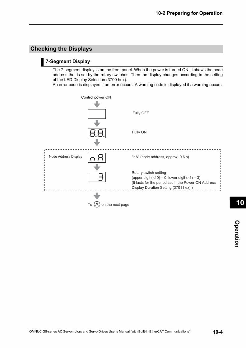
10-2 Preparing for Operation
10
Operation
Checking the Displays
7-Segment DisplayThe 7-segment display is on the front panel. When the power is turned ON, it shows the nodeaddress that is set by the rotary switches. Then the display changes according to the settingof the LED Display Selection (3700 hex).An error code is displayed if an error occurs. A warning code is displayed if a warning occurs.
Control power ON
Fully OFF
Fully ON
"nA" (node address, approx. 0.6 s)
Rotary switch setting (upper digit (×10) = 0, lower digit (×1) = 3)(It lasts for the period set in the Power ON Address Display Duration Setting (3701 hex).)
Node Address Display
ATo on the next page
10-4OMNUC G5-series AC Servomotors and Servo Drives User’s Manual (with Built-in EtherCAT Communications)
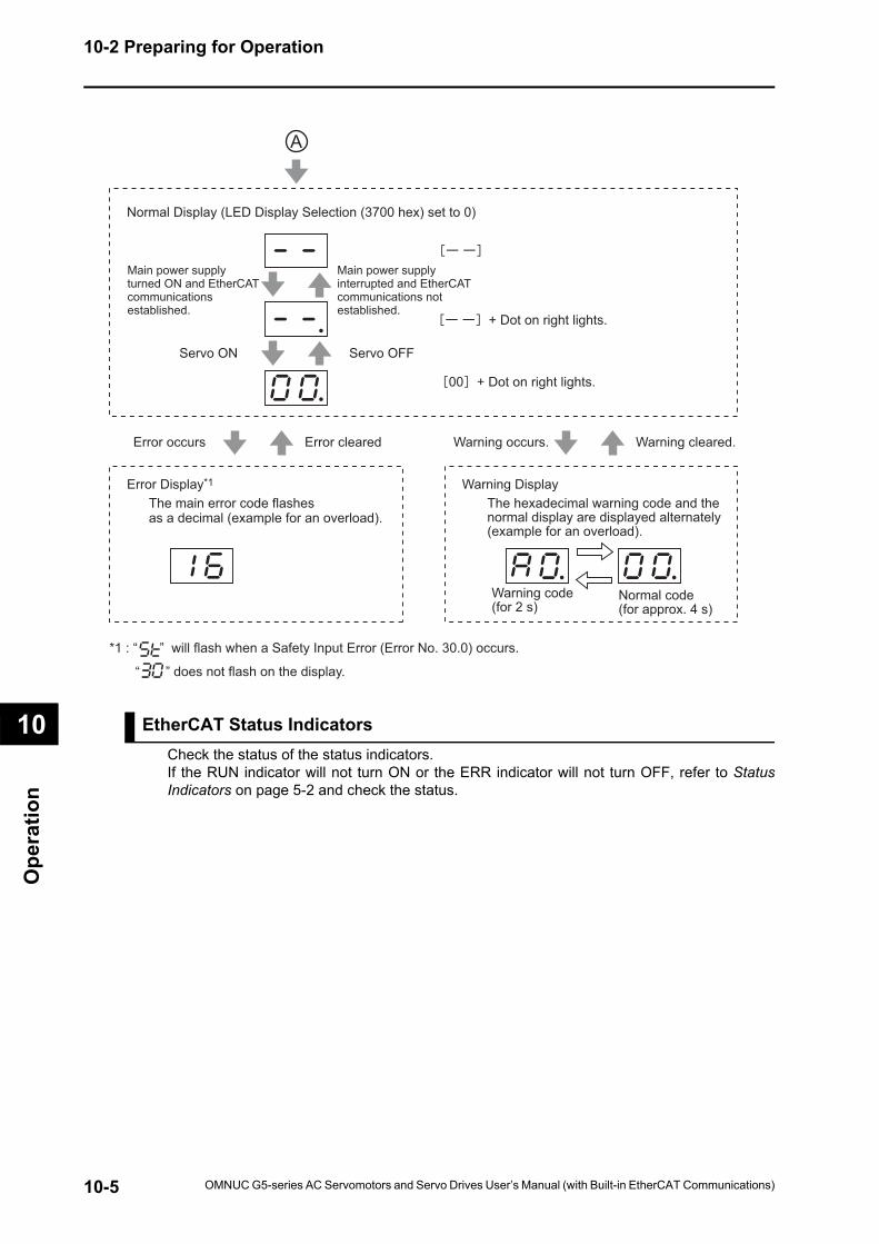
10-2 Preparing for Operation
10
Ope
ratio
n
EtherCAT Status IndicatorsCheck the status of the status indicators. If the RUN indicator will not turn ON or the ERR indicator will not turn OFF, refer to StatusIndicators on page 5-2 and check the status.
A
*1 : “ ” will flash when a Safety Input Error (Error No. 30.0) occurs.
“ ” does not flash on the display.
Warning occurs. Warning cleared.
Servo ON Servo OFF
+ Dot on right lights.
+ Dot on right lights.
Error occurs Error cleared
Warning code (for 2 s)
Normal code (for approx. 4 s)
Error Display*1
Normal Display (LED Display Selection (3700 hex) set to 0)
The main error code flashes as a decimal (example for an overload).
Warning Display
Main power supply turned ON and EtherCAT communications established.
Main power supply interrupted and EtherCAT communications not established.
The hexadecimal warning code and the normal display are displayed alternately (example for an overload).
10-5 OMNUC G5-series AC Servomotors and Servo Drives User’s Manual (with Built-in EtherCAT Communications)
10-2 Preparing for Operation
10
Operation
Absolute Encoder SetupYou must set up the absolute encoder if using a motor with an absolute encoder. The setup isrequired when you turn ON the power supply for the first time, when an Absolute EncoderSystem Down Error (Error No. 40) occurs, or when the encoder cable is disconnected and thenconnected again.To use an absolute encoder, set the Operation Switch when Using Absolute Encoder (3015hex) to 0 or 2 (factory setting).Refer to the SYSMAC CJ1W-NC281/NC481/NC881/NCF81/NC482/NC882 Position ControlUnit Operation Manual (Cat. No. W487) and to information on Absolute Encoder Setup (4102hex) to set up the absolute encoder.
Setting Up an Absolute Encoder from the CX-Drive1. Start the CX-Drive and go online with the Servo Drive via EtherCAT or
USB communications. 2. Select Absolute Encoder from the Tuning Menu of the CX-Drive. 3. Select Multi-Turn Data and Encoder Error Clear from the Absolute
Encoder Dialog Box. The following error will occur after execution has been completed.
EtherCAT communications: Absolute Value Cleared (Error No. 27.1) USB communications: Position Data Initialized (Error No. 27.7)
4. Turn the power supply to the Servo Drive OFF and then ON again.
ABS
10-6OMNUC G5-series AC Servomotors and Servo Drives User’s Manual (with Built-in EtherCAT Communications)
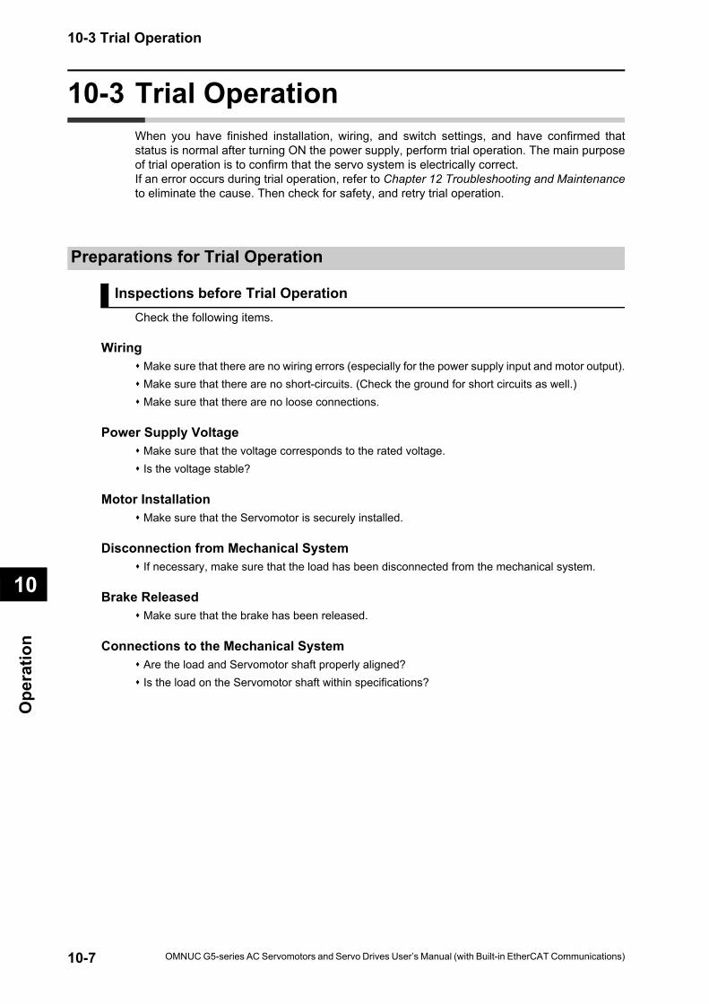
10-3 Trial Operation
10
Ope
ratio
n
10-3 Trial OperationWhen you have finished installation, wiring, and switch settings, and have confirmed thatstatus is normal after turning ON the power supply, perform trial operation. The main purposeof trial operation is to confirm that the servo system is electrically correct.If an error occurs during trial operation, refer to Chapter 12 Troubleshooting and Maintenanceto eliminate the cause. Then check for safety, and retry trial operation.
Preparations for Trial Operation
Inspections before Trial OperationCheck the following items.
WiringMake sure that there are no wiring errors (especially for the power supply input and motor output).Make sure that there are no short-circuits. (Check the ground for short circuits as well.)Make sure that there are no loose connections.
Power Supply VoltageMake sure that the voltage corresponds to the rated voltage.Is the voltage stable?
Motor InstallationMake sure that the Servomotor is securely installed.
Disconnection from Mechanical SystemIf necessary, make sure that the load has been disconnected from the mechanical system.
Brake ReleasedMake sure that the brake has been released.
Connections to the Mechanical SystemAre the load and Servomotor shaft properly aligned? Is the load on the Servomotor shaft within specifications?
10-7 OMNUC G5-series AC Servomotors and Servo Drives User’s Manual (with Built-in EtherCAT Communications)
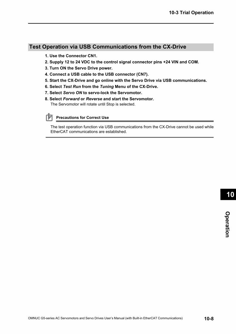
10-3 Trial Operation
10
Operation
Test Operation via USB Communications from the CX-Drive1. Use the Connector CN1.2. Supply 12 to 24 VDC to the control signal connector pins +24 VIN and COM.3. Turn ON the Servo Drive power.4. Connect a USB cable to the USB connector (CN7). 5. Start the CX-Drive and go online with the Servo Drive via USB communications. 6. Select Test Run from the Tuning Menu of the CX-Drive. 7. Select Servo ON to servo-lock the Servomotor. 8. Select Forward or Reverse and start the Servomotor.
The Servomotor will rotate until Stop is selected.
Precautions for Correct Use
The test operation function via USB communications from the CX-Drive cannot be used whileEtherCAT communications are established.
10-8OMNUC G5-series AC Servomotors and Servo Drives User’s Manual (with Built-in EtherCAT Communications)

11
Adjustment FunctionsThis chapter explains the functions, setting methods, and items to note regardingvarious gain adjustments.11-1 Analog Monitor.........................................................11-111-2 Gain Adjustment ......................................................11-411-3 Realtime Autotuning ................................................11-611-4 Manual Tuning........................................................11-1311-5 Damping Control ....................................................11-1511-6 Adaptive Filter ........................................................11-1811-7 Notch Filters ...........................................................11-2111-8 Disturbance Observer Function ...........................11-2411-9 Friction Torque Compensation Function.............11-2611-10 Hybrid Vibration Suppression Function ..............11-2811-11 Feed-forward Function ..........................................11-2911-12 Instantaneous Speed Observer Function ............11-32
OMNUC G5-series AC Servomotors and Servo Drives User’s Manual (with Built-in EtherCAT Communications)
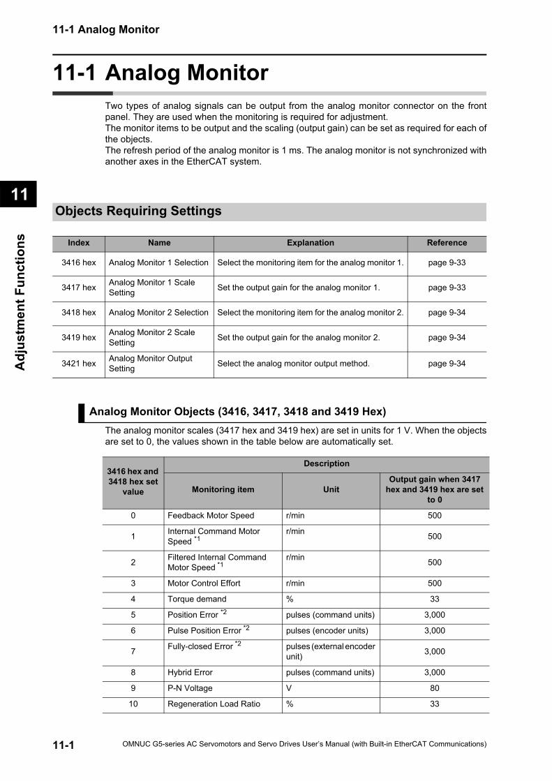
11-1 Analog Monitor
11
Adj
ustm
ent F
unct
ions
11-1 Analog MonitorTwo types of analog signals can be output from the analog monitor connector on the frontpanel. They are used when the monitoring is required for adjustment.The monitor items to be output and the scaling (output gain) can be set as required for each ofthe objects. The refresh period of the analog monitor is 1 ms. The analog monitor is not synchronized withanother axes in the EtherCAT system.
Objects Requiring Settings
Analog Monitor Objects (3416, 3417, 3418 and 3419 Hex)The analog monitor scales (3417 hex and 3419 hex) are set in units for 1 V. When the objectsare set to 0, the values shown in the table below are automatically set.
Index Name Explanation Reference
3416 hex Analog Monitor 1 Selection Select the monitoring item for the analog monitor 1. page 9-33
3417 hex Analog Monitor 1 Scale Setting Set the output gain for the analog monitor 1. page 9-33
3418 hex Analog Monitor 2 Selection Select the monitoring item for the analog monitor 2. page 9-34
3419 hex Analog Monitor 2 Scale Setting Set the output gain for the analog monitor 2. page 9-34
3421 hex Analog Monitor Output Setting Select the analog monitor output method. page 9-34
3416 hex and 3418 hex set
value
Description
Monitoring item UnitOutput gain when 3417
hex and 3419 hex are set to 0
0 Feedback Motor Speed r/min 500
1 Internal Command Motor Speed *1
r/min 500
2 Filtered Internal Command Motor Speed *1
r/min 500
3 Motor Control Effort r/min 500
4 Torque demand % 33
5 Position Error *2 pulses (command units) 3,000
6 Pulse Position Error *2 pulses (encoder units) 3,000
7 Fully-closed Error *2 pulses (external encoder unit) 3,000
8 Hybrid Error pulses (command units) 3,000
9 P-N Voltage V 80
10 Regeneration Load Ratio % 33
11-1 OMNUC G5-series AC Servomotors and Servo Drives User’s Manual (with Built-in EtherCAT Communications)
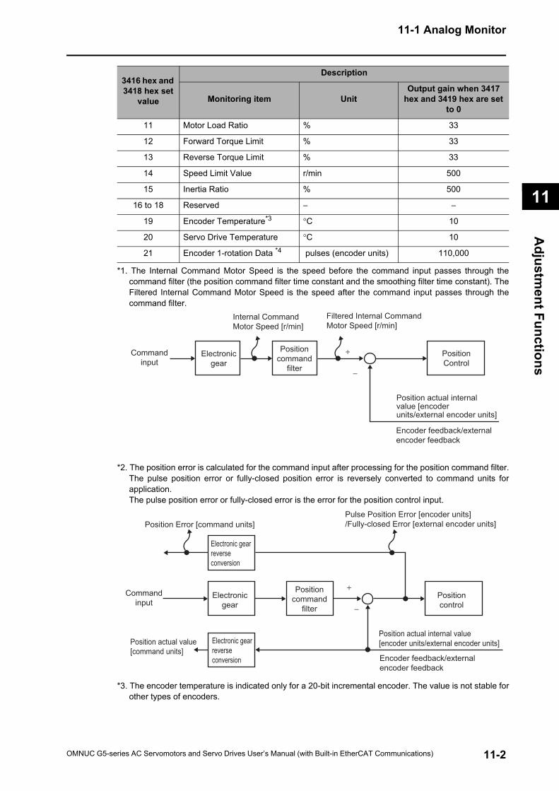
11-1 Analog Monitor
11
Adjustm
ent Functions
11 Motor Load Ratio % 33
12 Forward Torque Limit % 33
13 Reverse Torque Limit % 33
14 Speed Limit Value r/min 500
15 Inertia Ratio % 500
16 to 18 Reserved − −
19 Encoder Temperature*3 °C 10
20 Servo Drive Temperature °C 10
21 Encoder 1-rotation Data *4 pulses (encoder units) 110,000
*1. The Internal Command Motor Speed is the speed before the command input passes through thecommand filter (the position command filter time constant and the smoothing filter time constant). TheFiltered Internal Command Motor Speed is the speed after the command input passes through thecommand filter.
*2. The position error is calculated for the command input after processing for the position command filter.The pulse position error or fully-closed position error is reversely converted to command units forapplication. The pulse position error or fully-closed error is the error for the position control input.
*3. The encoder temperature is indicated only for a 20-bit incremental encoder. The value is not stable forother types of encoders.
3416 hex and 3418 hex set
value
Description
Monitoring item UnitOutput gain when 3417
hex and 3419 hex are set to 0
Commandinput
Electronicgear
Internal Command Motor Speed [r/min]
Filtered Internal Command Motor Speed [r/min]
+
−
Positioncommand
filter
PositionControl
Encoder feedback/externalencoder feedback
Position actual internal value [encoder units/external encoder units]
Commandinput
Electronicgear
Pulse Position Error [encoder units]/Fully-closed Error [external encoder units]
Positioncommand
filter
Positioncontrol
Encoder feedback/externalencoder feedback
Position Error [command units]
Electronic gearreverseconversion
Position actual internal value [encoder units/external encoder units]Position actual value
[command units]Electronic gearreverseconversion
+
−
11-2OMNUC G5-series AC Servomotors and Servo Drives User’s Manual (with Built-in EtherCAT Communications)
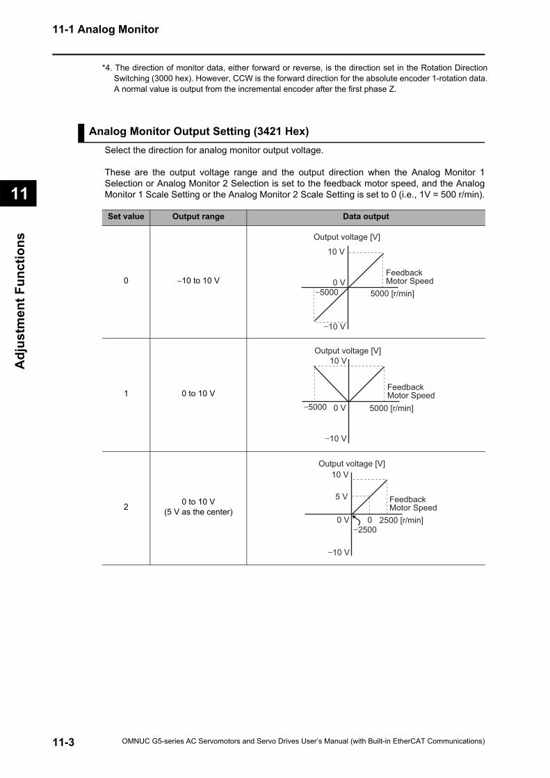
11-1 Analog Monitor
11
Adj
ustm
ent F
unct
ions
Analog Monitor Output Setting (3421 Hex)Select the direction for analog monitor output voltage.
These are the output voltage range and the output direction when the Analog Monitor 1Selection or Analog Monitor 2 Selection is set to the feedback motor speed, and the AnalogMonitor 1 Scale Setting or the Analog Monitor 2 Scale Setting is set to 0 (i.e., 1V = 500 r/min).
*4. The direction of monitor data, either forward or reverse, is the direction set in the Rotation DirectionSwitching (3000 hex). However, CCW is the forward direction for the absolute encoder 1-rotation data.A normal value is output from the incremental encoder after the first phase Z.
Set value Output range Data output
0 −10 to 10 V
1 0 to 10 V
2 0 to 10 V(5 V as the center)
10 V
−10 V
0 V−5000 5000 [r/min]
Feedback Motor Speed
Output voltage [V]
10 V
−10 V
0 V−5000 5000 [r/min]
Output voltage [V]
Feedback Motor Speed
10 V
5 V
−10 V
0 V 0−2500
2500 [r/min]
Output voltage [V]
Feedback Motor Speed
11-3 OMNUC G5-series AC Servomotors and Servo Drives User’s Manual (with Built-in EtherCAT Communications)
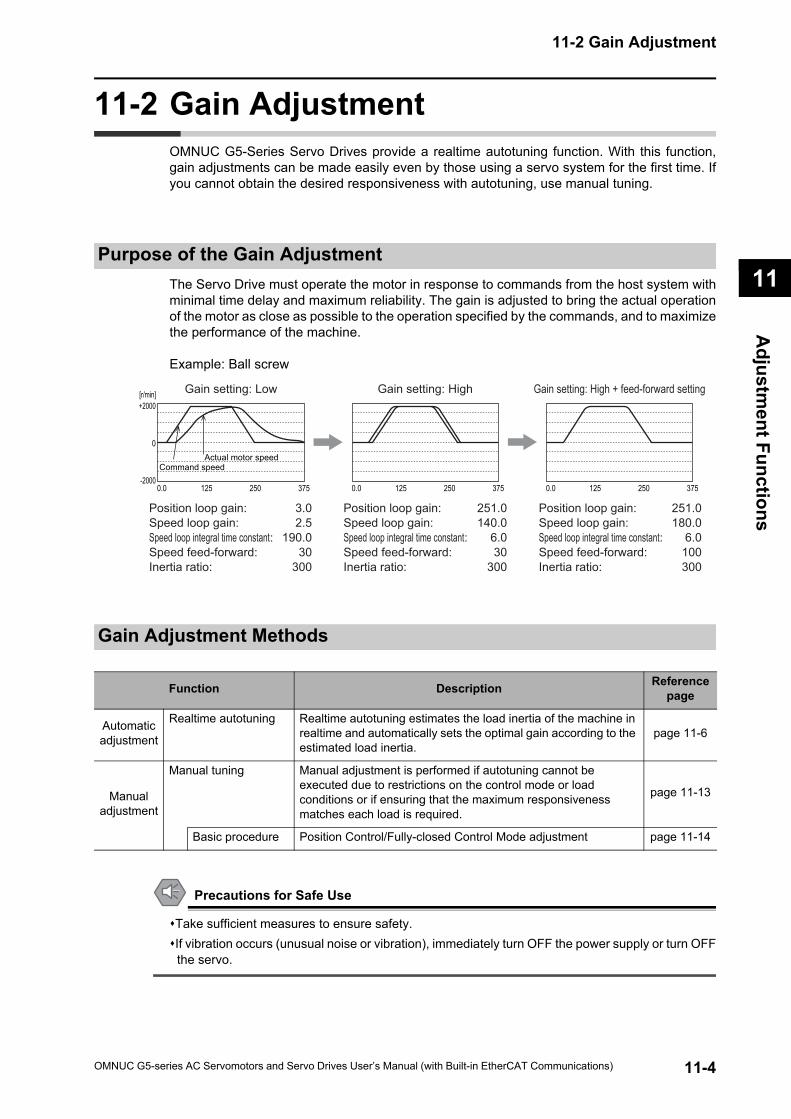
11-2 Gain Adjustment
11
Adjustm
ent Functions
11-2 Gain AdjustmentOMNUC G5-Series Servo Drives provide a realtime autotuning function. With this function,gain adjustments can be made easily even by those using a servo system for the first time. Ifyou cannot obtain the desired responsiveness with autotuning, use manual tuning.
Purpose of the Gain AdjustmentThe Servo Drive must operate the motor in response to commands from the host system withminimal time delay and maximum reliability. The gain is adjusted to bring the actual operationof the motor as close as possible to the operation specified by the commands, and to maximizethe performance of the machine.
Example: Ball screw
Gain Adjustment Methods
Precautions for Safe Use
Take sufficient measures to ensure safety.If vibration occurs (unusual noise or vibration), immediately turn OFF the power supply or turn OFFthe servo.
3.02.5
190.030
300
251.0140.0
6.030
300
0
0.0 375250125 0.0 375250125 0.0 375250125
251.0180.0
6.0100300
Gain setting: Low Gain setting: High Gain setting: High + feed-forward setting[r/min]
Command speedActual motor speed
Position loop gain: Speed loop gain:Speed loop integral time constant: Speed feed-forward: Inertia ratio:
Position loop gain:Speed loop gain: Speed loop integral time constant: Speed feed-forward: Inertia ratio:
Position loop gain:Speed loop gain: Speed loop integral time constant: Speed feed-forward: Inertia ratio:
+2000
-2000
Function Description Reference page
Automatic adjustment
Realtime autotuning Realtime autotuning estimates the load inertia of the machine in realtime and automatically sets the optimal gain according to the estimated load inertia.
page 11-6
Manual adjustment
Manual tuning Manual adjustment is performed if autotuning cannot be executed due to restrictions on the control mode or load conditions or if ensuring that the maximum responsiveness matches each load is required.
page 11-13
Basic procedure Position Control/Fully-closed Control Mode adjustment page 11-14
11-4OMNUC G5-series AC Servomotors and Servo Drives User’s Manual (with Built-in EtherCAT Communications)
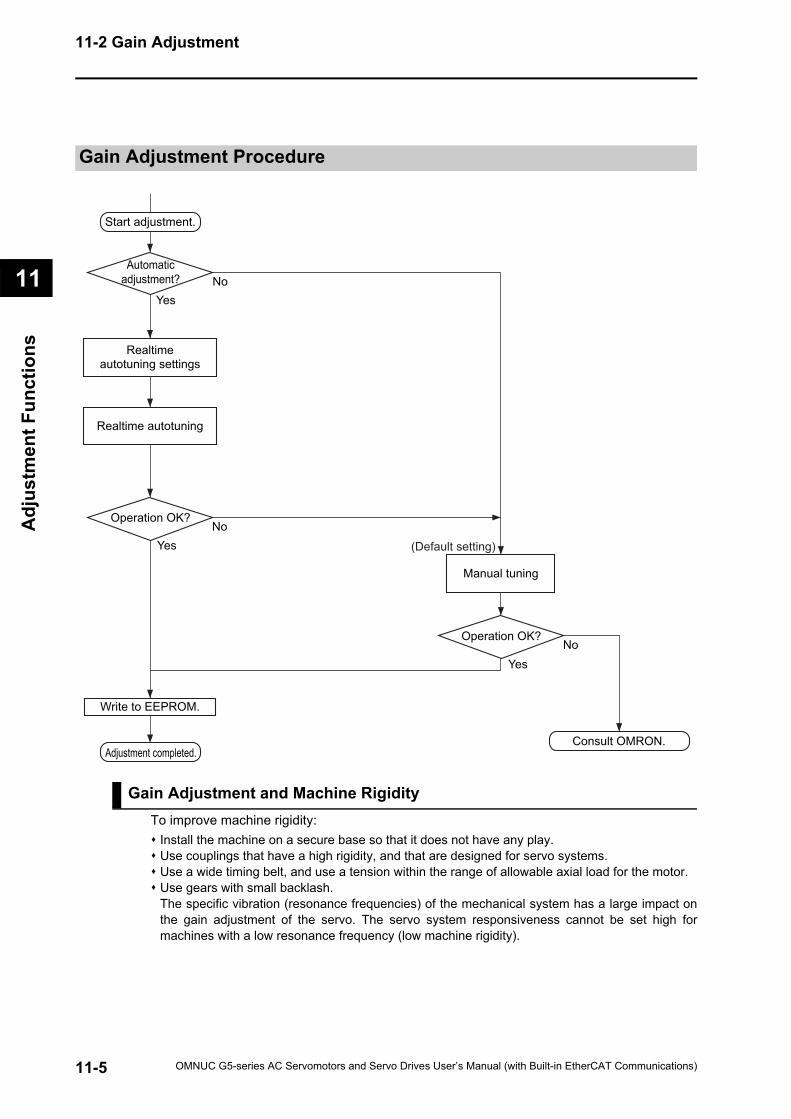
11-2 Gain Adjustment
11
Adj
ustm
ent F
unct
ions
Gain Adjustment Procedure
Gain Adjustment and Machine RigidityTo improve machine rigidity:
Install the machine on a secure base so that it does not have any play.Use couplings that have a high rigidity, and that are designed for servo systems.Use a wide timing belt, and use a tension within the range of allowable axial load for the motor.Use gears with small backlash.The specific vibration (resonance frequencies) of the mechanical system has a large impact onthe gain adjustment of the servo. The servo system responsiveness cannot be set high formachines with a low resonance frequency (low machine rigidity).
Start adjustment.
Automaticadjustment?
Operation OK?
Yes
YesNo
Operation OK?
YesNo
No
Realtime autotuning
Realtimeautotuning settings
Manual tuning
Adjustment completed.
Write to EEPROM.
Consult OMRON.
(Default setting)
11-5 OMNUC G5-series AC Servomotors and Servo Drives User’s Manual (with Built-in EtherCAT Communications)
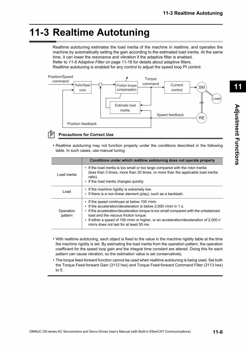
11-3 Realtime Autotuning
11
Adjustm
ent Functions
11-3 Realtime AutotuningRealtime autotuning estimates the load inertia of the machine in realtime, and operates themachine by automatically setting the gain according to the estimated load inertia. At the sametime, it can lower the resonance and vibration if the adaptive filter is enabled.Refer to 11-6 Adaptive Filter on page 11-18 for details about adaptive filters.Realtime autotuning is enabled for any control to adjust the speed loop PI control.
Precautions for Correct Use
Realtime autotuning may not function properly under the conditions described in the followingtable. In such cases, use manual tuning.
With realtime autotuning, each object is fixed to the value in the machine rigidity table at the timethe machine rigidity is set. By estimating the load inertia from the operation pattern, the operationcoefficient for the speed loop gain and the integral time constant are altered. Doing this for eachpattern can cause vibration, so the estimation value is set conservatively.The torque feed-forward function cannot be used when realtime autotuning is being used. Set boththe Torque Feed-forward Gain (3112 hex) and Torque Feed-forward Command Filter (3113 hex)to 0.
SM
RE
Position/Speedcommand
Speed feedback
Position/Speedcontrol
Currentcontrol
Torquecommand
Load
Friction torquecompensation
Position feedback
Estimate loadinertia.
Conditions under which realtime autotuning does not operate properly
Load inertia
• If the load inertia is too small or too large compared with the rotor inertia(less than 3 times, more than 20 times, or more than the applicable load inertia ratio).
• If the load inertia changes quickly.
Load • If the machine rigidity is extremely low.• If there is a non-linear element (play), such as a backlash.
Operation pattern
• If the speed continues at below 100 r/min.• If the acceleration/deceleration is below 2,000 r/min in 1 s.• If the acceleration/deceleration torque is too small compared with the unbalanced
load and the viscous friction torque.• If either a speed of 100 r/min or higher, or an acceleration/deceleration of 2,000 r/
min/s does not last for at least 50 ms.
11-6OMNUC G5-series AC Servomotors and Servo Drives User’s Manual (with Built-in EtherCAT Communications)
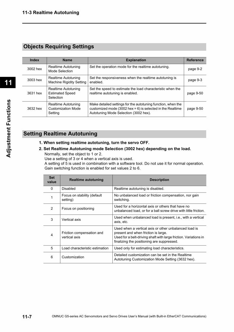
11-3 Realtime Autotuning
11
Adj
ustm
ent F
unct
ions
Objects Requiring Settings
Setting Realtime Autotuning1. When setting realtime autotuning, turn the servo OFF.2. Set Realtime Autotuning mode Selection (3002 hex) depending on the load.
Normally, set the object to 1 or 2.Use a setting of 3 or 4 when a vertical axis is used.A setting of 5 is used in combination with a software tool. Do not use it for normal operation. Gain switching function is enabled for set values 2 to 6.
Index Name Explanation Reference
3002 hex Realtime Autotuning Mode Selection
Set the operation mode for the realtime autotuning. page 9-2
3003 hex Realtime Autotuning Machine Rigidity Setting
Set the responsiveness when the realtime autotuning is enabled. page 9-3
3631 hexRealtime Autotuning Estimated Speed Selection
Set the speed to estimate the load characteristic when the realtime autotuning is enabled. page 9-50
3632 hexRealtime Autotuning Customization Mode Setting
Make detailed settings for the autotuning function, when the customized mode (3002 hex = 6) is selected in the Realtime Autotuning Mode Selection (3002 hex).
page 9-50
Set value Realtime autotuning Description
0 Disabled Realtime autotuning is disabled.
1 Focus on stability (default setting)
No unbalanced load or friction compensation, nor gain switching.
2 Focus on positioning Used for a horizontal axis or others that have no unbalanced load, or for a ball screw drive with little friction.
3 Vertical axis Used when unbalanced load is present, i.e., with a vertical axis, etc.
4 Friction compensation and vertical axis
Used when a vertical axis or other unbalanced load is present and when friction is large.Used for a belt-driving shaft with large friction. Variations in finalizing the positioning are suppressed.
5 Load characteristic estimation Used only for estimating load characteristics.
6 Customization Detailed customization can be set in the Realtime Autotuning Customization Mode Setting (3632 hex).
11-7 OMNUC G5-series AC Servomotors and Servo Drives User’s Manual (with Built-in EtherCAT Communications)
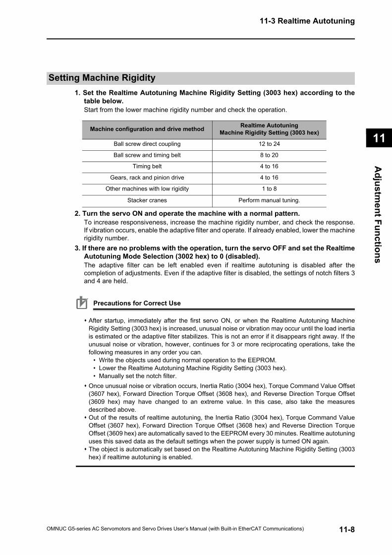
11-3 Realtime Autotuning
11
Adjustm
ent Functions
Setting Machine Rigidity1. Set the Realtime Autotuning Machine Rigidity Setting (3003 hex) according to the
table below.Start from the lower machine rigidity number and check the operation.
2. Turn the servo ON and operate the machine with a normal pattern.To increase responsiveness, increase the machine rigidity number, and check the response.If vibration occurs, enable the adaptive filter and operate. If already enabled, lower the machinerigidity number.
3. If there are no problems with the operation, turn the servo OFF and set the RealtimeAutotuning Mode Selection (3002 hex) to 0 (disabled).The adaptive filter can be left enabled even if realtime autotuning is disabled after thecompletion of adjustments. Even if the adaptive filter is disabled, the settings of notch filters 3and 4 are held.
Precautions for Correct Use
After startup, immediately after the first servo ON, or when the Realtime Autotuning MachineRigidity Setting (3003 hex) is increased, unusual noise or vibration may occur until the load inertiais estimated or the adaptive filter stabilizes. This is not an error if it disappears right away. If theunusual noise or vibration, however, continues for 3 or more reciprocating operations, take thefollowing measures in any order you can.
• Write the objects used during normal operation to the EEPROM.• Lower the Realtime Autotuning Machine Rigidity Setting (3003 hex).• Manually set the notch filter.
Once unusual noise or vibration occurs, Inertia Ratio (3004 hex), Torque Command Value Offset(3607 hex), Forward Direction Torque Offset (3608 hex), and Reverse Direction Torque Offset(3609 hex) may have changed to an extreme value. In this case, also take the measuresdescribed above.Out of the results of realtime autotuning, the Inertia Ratio (3004 hex), Torque Command ValueOffset (3607 hex), Forward Direction Torque Offset (3608 hex) and Reverse Direction TorqueOffset (3609 hex) are automatically saved to the EEPROM every 30 minutes. Realtime autotuninguses this saved data as the default settings when the power supply is turned ON again.The object is automatically set based on the Realtime Autotuning Machine Rigidity Setting (3003hex) if realtime autotuning is enabled.
Machine configuration and drive method Realtime AutotuningMachine Rigidity Setting (3003 hex)
Ball screw direct coupling 12 to 24
Ball screw and timing belt 8 to 20
Timing belt 4 to 16
Gears, rack and pinion drive 4 to 16
Other machines with low rigidity 1 to 8
Stacker cranes Perform manual tuning.
11-8OMNUC G5-series AC Servomotors and Servo Drives User’s Manual (with Built-in EtherCAT Communications)
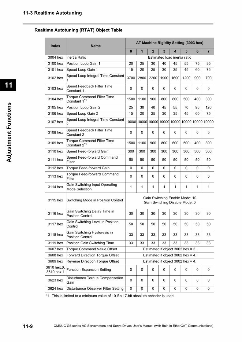
11-3 Realtime Autotuning
11
Adj
ustm
ent F
unct
ions
Realtime Autotuning (RTAT) Object Table
*1. This is limited to a minimum value of 10 if a 17-bit absolute encoder is used.
Index NameAT Machine Rigidity Setting (3003 hex)
0 1 2 3 4 5 6 73004 hex Inertia Ratio Estimated load inertia ratio
3100 hex Position Loop Gain 1 20 25 30 40 45 55 75 95
3101 hex Speed Loop Gain 1 15 20 25 30 35 45 60 75
3102 hex Speed Loop Integral Time Constant 1 3700 2800 2200 1900 1600 1200 900 700
3103 hex Speed Feedback Filter Time Constant 1 0 0 0 0 0 0 0 0
3104 hex Torque Command Filter Time Constant 1*1 1500 1100 900 800 600 500 400 300
3105 hex Position Loop Gain 2 25 30 40 45 55 70 95 120
3106 hex Speed Loop Gain 2 15 20 25 30 35 45 60 75
3107 hex Speed Loop Integral Time Constant 2 10000 10000 10000 10000 10000 10000 10000 10000
3108 hex Speed Feedback Filter Time Constant 2 0 0 0 0 0 0 0 0
3109 hex Torque Command Filter Time Constant 2*1 1500 1100 900 800 600 500 400 300
3110 hex Speed Feed-forward Gain 300 300 300 300 300 300 300 300
3111 hex Speed Feed-forward Command Filter 50 50 50 50 50 50 50 50
3112 hex Torque Feed-forward Gain 0 0 0 0 0 0 0 0
3113 hex Torque Feed-forward Command Filter 0 0 0 0 0 0 0 0
3114 hex Gain Switching Input Operating Mode Selection 1 1 1 1 1 1 1 1
3115 hex Switching Mode in Position Control Gain Switching Enable Mode: 10Gain Switching Disable Mode: 0
3116 hex Gain Switching Delay Time in Position Control 30 30 30 30 30 30 30 30
3117 hex Gain Switching Level in Position Control 50 50 50 50 50 50 50 50
3118 hex Gain Switching Hysteresis in Position Control 33 33 33 33 33 33 33 33
3119 hex Position Gain Switching Time 33 33 33 33 33 33 33 33
3607 hex Torque Command Value Offset Estimated if object 3002 hex = 3.
3608 hex Forward Direction Torque Offset Estimated if object 3002 hex = 4.
3609 hex Reverse Direction Torque Offset Estimated if object 3002 hex = 4.
3610 hex.0, 3610 hex.1 Function Expansion Setting 0 0 0 0 0 0 0 0
3623 hex Disturbance Torque Compensation Gain 0 0 0 0 0 0 0 0
3624 hex Disturbance Observer Filter Setting 0 0 0 0 0 0 0 0
11-9 OMNUC G5-series AC Servomotors and Servo Drives User’s Manual (with Built-in EtherCAT Communications)
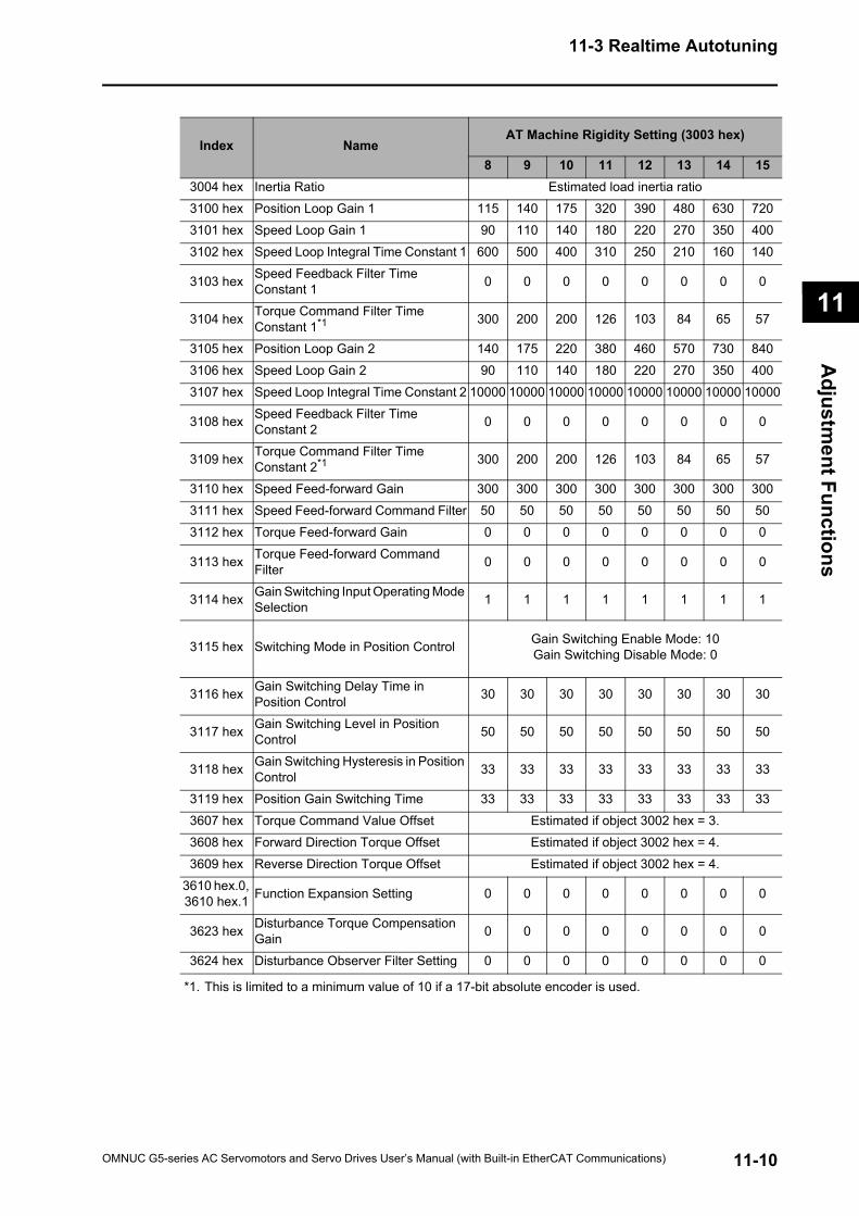
11-3 Realtime Autotuning
11
Adjustm
ent Functions
*1. This is limited to a minimum value of 10 if a 17-bit absolute encoder is used.
Index NameAT Machine Rigidity Setting (3003 hex)
8 9 10 11 12 13 14 153004 hex Inertia Ratio Estimated load inertia ratio
3100 hex Position Loop Gain 1 115 140 175 320 390 480 630 720
3101 hex Speed Loop Gain 1 90 110 140 180 220 270 350 400
3102 hex Speed Loop Integral Time Constant 1 600 500 400 310 250 210 160 140
3103 hex Speed Feedback Filter Time Constant 1 0 0 0 0 0 0 0 0
3104 hex Torque Command Filter Time Constant 1*1 300 200 200 126 103 84 65 57
3105 hex Position Loop Gain 2 140 175 220 380 460 570 730 840
3106 hex Speed Loop Gain 2 90 110 140 180 220 270 350 400
3107 hex Speed Loop Integral Time Constant 2 10000 10000 10000 10000 10000 10000 10000 10000
3108 hex Speed Feedback Filter Time Constant 2 0 0 0 0 0 0 0 0
3109 hex Torque Command Filter Time Constant 2*1 300 200 200 126 103 84 65 57
3110 hex Speed Feed-forward Gain 300 300 300 300 300 300 300 300
3111 hex Speed Feed-forward Command Filter 50 50 50 50 50 50 50 50
3112 hex Torque Feed-forward Gain 0 0 0 0 0 0 0 0
3113 hex Torque Feed-forward Command Filter 0 0 0 0 0 0 0 0
3114 hex Gain Switching Input Operating Mode Selection 1 1 1 1 1 1 1 1
3115 hex Switching Mode in Position Control Gain Switching Enable Mode: 10Gain Switching Disable Mode: 0
3116 hex Gain Switching Delay Time in Position Control 30 30 30 30 30 30 30 30
3117 hex Gain Switching Level in Position Control 50 50 50 50 50 50 50 50
3118 hex Gain Switching Hysteresis in Position Control 33 33 33 33 33 33 33 33
3119 hex Position Gain Switching Time 33 33 33 33 33 33 33 33
3607 hex Torque Command Value Offset Estimated if object 3002 hex = 3.
3608 hex Forward Direction Torque Offset Estimated if object 3002 hex = 4.
3609 hex Reverse Direction Torque Offset Estimated if object 3002 hex = 4.
3610 hex.0, 3610 hex.1 Function Expansion Setting 0 0 0 0 0 0 0 0
3623 hex Disturbance Torque Compensation Gain 0 0 0 0 0 0 0 0
3624 hex Disturbance Observer Filter Setting 0 0 0 0 0 0 0 0
11-10OMNUC G5-series AC Servomotors and Servo Drives User’s Manual (with Built-in EtherCAT Communications)
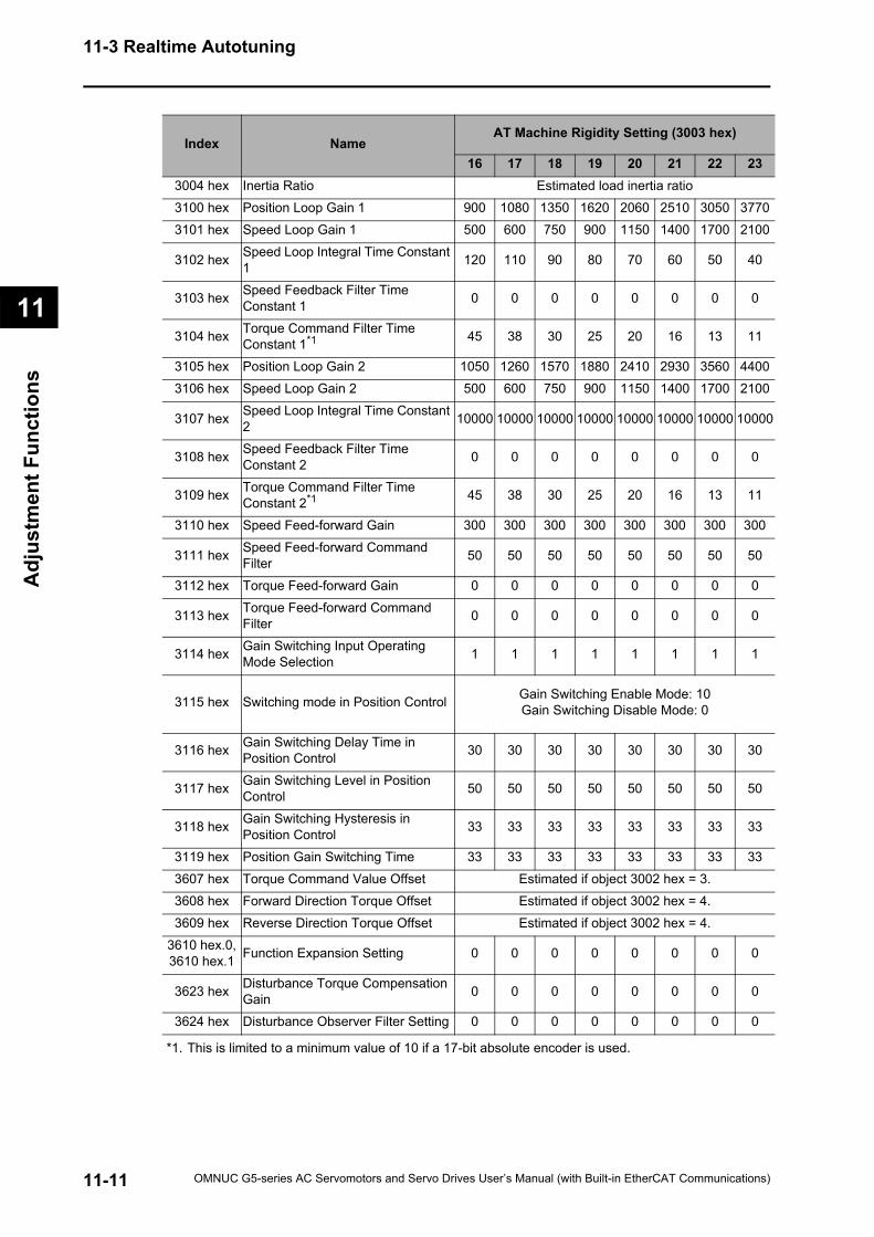
11-3 Realtime Autotuning
11
Adj
ustm
ent F
unct
ions
*1. This is limited to a minimum value of 10 if a 17-bit absolute encoder is used.
Index NameAT Machine Rigidity Setting (3003 hex)
16 17 18 19 20 21 22 233004 hex Inertia Ratio Estimated load inertia ratio
3100 hex Position Loop Gain 1 900 1080 1350 1620 2060 2510 3050 3770
3101 hex Speed Loop Gain 1 500 600 750 900 1150 1400 1700 2100
3102 hex Speed Loop Integral Time Constant 1 120 110 90 80 70 60 50 40
3103 hex Speed Feedback Filter Time Constant 1 0 0 0 0 0 0 0 0
3104 hex Torque Command Filter Time Constant 1*1 45 38 30 25 20 16 13 11
3105 hex Position Loop Gain 2 1050 1260 1570 1880 2410 2930 3560 4400
3106 hex Speed Loop Gain 2 500 600 750 900 1150 1400 1700 2100
3107 hex Speed Loop Integral Time Constant 2 10000 10000 10000 10000 10000 10000 10000 10000
3108 hex Speed Feedback Filter Time Constant 2 0 0 0 0 0 0 0 0
3109 hex Torque Command Filter Time Constant 2*1 45 38 30 25 20 16 13 11
3110 hex Speed Feed-forward Gain 300 300 300 300 300 300 300 300
3111 hex Speed Feed-forward Command Filter 50 50 50 50 50 50 50 50
3112 hex Torque Feed-forward Gain 0 0 0 0 0 0 0 0
3113 hex Torque Feed-forward Command Filter 0 0 0 0 0 0 0 0
3114 hex Gain Switching Input Operating Mode Selection 1 1 1 1 1 1 1 1
3115 hex Switching mode in Position Control Gain Switching Enable Mode: 10Gain Switching Disable Mode: 0
3116 hex Gain Switching Delay Time in Position Control 30 30 30 30 30 30 30 30
3117 hex Gain Switching Level in Position Control 50 50 50 50 50 50 50 50
3118 hex Gain Switching Hysteresis in Position Control 33 33 33 33 33 33 33 33
3119 hex Position Gain Switching Time 33 33 33 33 33 33 33 33
3607 hex Torque Command Value Offset Estimated if object 3002 hex = 3.
3608 hex Forward Direction Torque Offset Estimated if object 3002 hex = 4.
3609 hex Reverse Direction Torque Offset Estimated if object 3002 hex = 4.
3610 hex.0, 3610 hex.1 Function Expansion Setting 0 0 0 0 0 0 0 0
3623 hex Disturbance Torque Compensation Gain 0 0 0 0 0 0 0 0
3624 hex Disturbance Observer Filter Setting 0 0 0 0 0 0 0 0
11-11 OMNUC G5-series AC Servomotors and Servo Drives User’s Manual (with Built-in EtherCAT Communications)
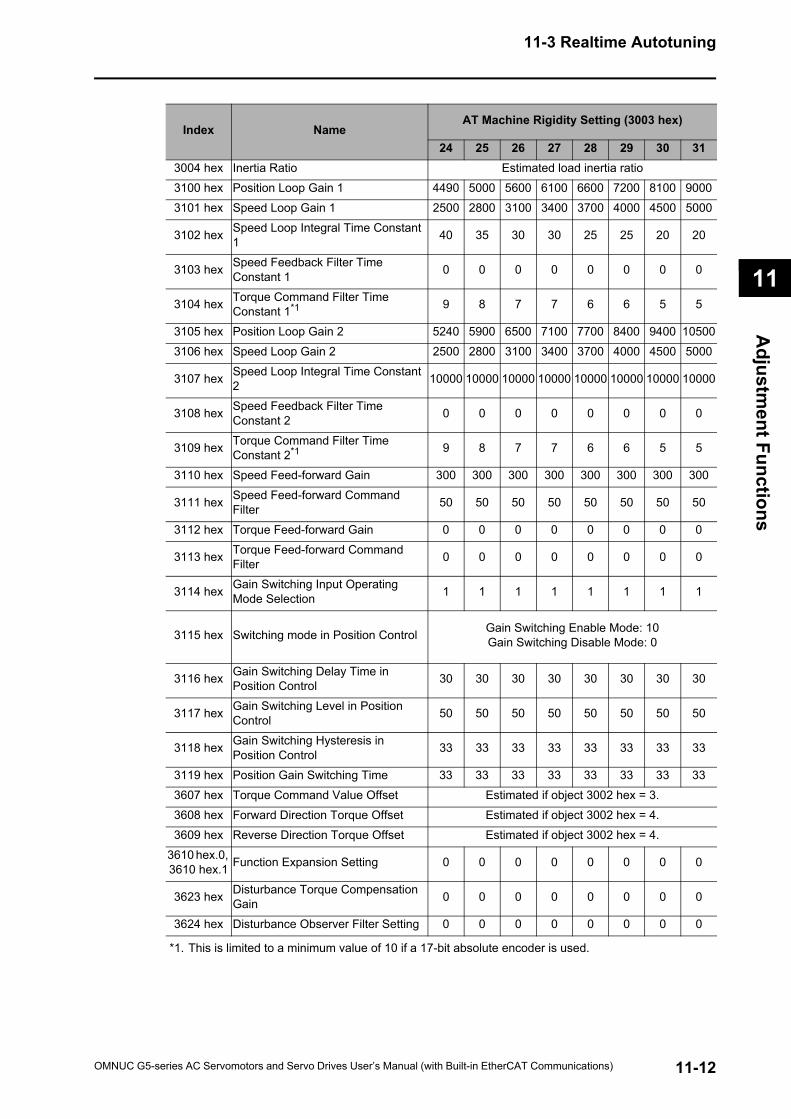
11-3 Realtime Autotuning
11
Adjustm
ent Functions
*1. This is limited to a minimum value of 10 if a 17-bit absolute encoder is used.
Index NameAT Machine Rigidity Setting (3003 hex)
24 25 26 27 28 29 30 313004 hex Inertia Ratio Estimated load inertia ratio
3100 hex Position Loop Gain 1 4490 5000 5600 6100 6600 7200 8100 9000
3101 hex Speed Loop Gain 1 2500 2800 3100 3400 3700 4000 4500 5000
3102 hex Speed Loop Integral Time Constant 1 40 35 30 30 25 25 20 20
3103 hex Speed Feedback Filter Time Constant 1 0 0 0 0 0 0 0 0
3104 hex Torque Command Filter Time Constant 1*1 9 8 7 7 6 6 5 5
3105 hex Position Loop Gain 2 5240 5900 6500 7100 7700 8400 9400 10500
3106 hex Speed Loop Gain 2 2500 2800 3100 3400 3700 4000 4500 5000
3107 hex Speed Loop Integral Time Constant 2 10000 10000 10000 10000 10000 10000 10000 10000
3108 hex Speed Feedback Filter Time Constant 2 0 0 0 0 0 0 0 0
3109 hex Torque Command Filter Time Constant 2*1 9 8 7 7 6 6 5 5
3110 hex Speed Feed-forward Gain 300 300 300 300 300 300 300 300
3111 hex Speed Feed-forward Command Filter 50 50 50 50 50 50 50 50
3112 hex Torque Feed-forward Gain 0 0 0 0 0 0 0 0
3113 hex Torque Feed-forward Command Filter 0 0 0 0 0 0 0 0
3114 hex Gain Switching Input Operating Mode Selection 1 1 1 1 1 1 1 1
3115 hex Switching mode in Position Control Gain Switching Enable Mode: 10Gain Switching Disable Mode: 0
3116 hex Gain Switching Delay Time in Position Control 30 30 30 30 30 30 30 30
3117 hex Gain Switching Level in Position Control 50 50 50 50 50 50 50 50
3118 hex Gain Switching Hysteresis in Position Control 33 33 33 33 33 33 33 33
3119 hex Position Gain Switching Time 33 33 33 33 33 33 33 33
3607 hex Torque Command Value Offset Estimated if object 3002 hex = 3.
3608 hex Forward Direction Torque Offset Estimated if object 3002 hex = 4.
3609 hex Reverse Direction Torque Offset Estimated if object 3002 hex = 4.
3610 hex.0, 3610 hex.1 Function Expansion Setting 0 0 0 0 0 0 0 0
3623 hex Disturbance Torque Compensation Gain 0 0 0 0 0 0 0 0
3624 hex Disturbance Observer Filter Setting 0 0 0 0 0 0 0 0
11-12OMNUC G5-series AC Servomotors and Servo Drives User’s Manual (with Built-in EtherCAT Communications)
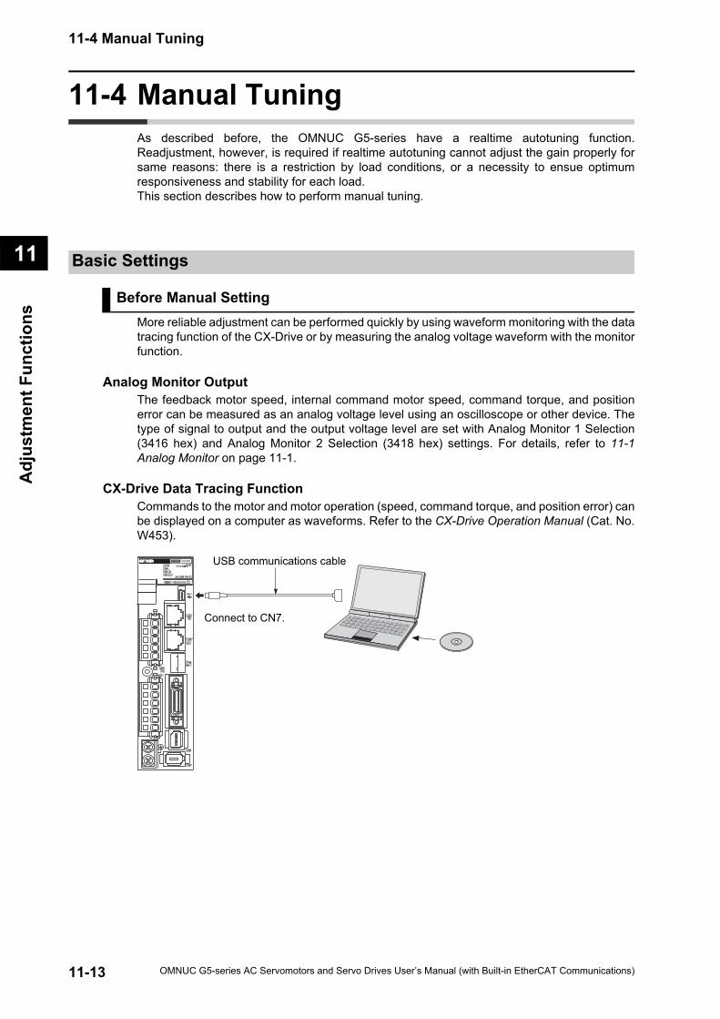
11-4 Manual Tuning
11
Adj
ustm
ent F
unct
ions
11-4 Manual TuningAs described before, the OMNUC G5-series have a realtime autotuning function.Readjustment, however, is required if realtime autotuning cannot adjust the gain properly forsame reasons: there is a restriction by load conditions, or a necessity to ensue optimumresponsiveness and stability for each load. This section describes how to perform manual tuning.
Basic Settings
Before Manual SettingMore reliable adjustment can be performed quickly by using waveform monitoring with the datatracing function of the CX-Drive or by measuring the analog voltage waveform with the monitorfunction.
Analog Monitor OutputThe feedback motor speed, internal command motor speed, command torque, and positionerror can be measured as an analog voltage level using an oscilloscope or other device. Thetype of signal to output and the output voltage level are set with Analog Monitor 1 Selection(3416 hex) and Analog Monitor 2 Selection (3418 hex) settings. For details, refer to 11-1Analog Monitor on page 11-1.
CX-Drive Data Tracing FunctionCommands to the motor and motor operation (speed, command torque, and position error) canbe displayed on a computer as waveforms. Refer to the CX-Drive Operation Manual (Cat. No.W453).
USB communications cable
Connect to CN7.
11-13 OMNUC G5-series AC Servomotors and Servo Drives User’s Manual (with Built-in EtherCAT Communications)
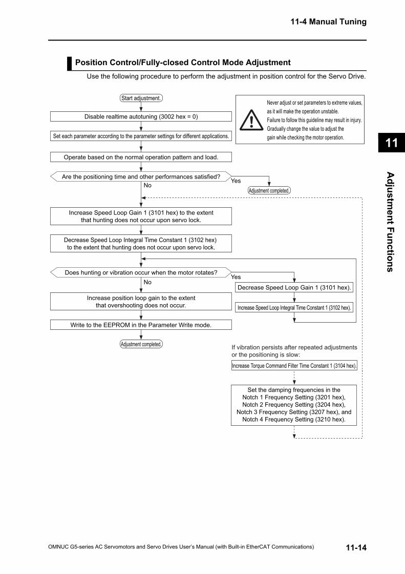
11-4 Manual Tuning
11
Adjustm
ent Functions
Position Control/Fully-closed Control Mode AdjustmentUse the following procedure to perform the adjustment in position control for the Servo Drive.
Write to the EEPROM in the Parameter Write mode.
Start adjustment.
YesNo
Adjustment completed.
Disable realtime autotuning (3002 hex = 0)
Set each parameter according to the parameter settings for different applications.
Operate based on the normal operation pattern and load.
Are the positioning time and other performances satisfied?
Adjustment completed.
Increase Speed Loop Gain 1 (3101 hex) to the extentthat hunting does not occur upon servo lock.
Decrease Speed Loop Integral Time Constant 1 (3102 hex) to the extent that hunting does not occur upon servo lock.
Does hunting or vibration occur when the motor rotates?No
Decrease Speed Loop Gain 1 (3101 hex).
Increase Speed Loop Integral Time Constant 1 (3102 hex).Increase position loop gain to the extent
that overshooting does not occur.
Yes
If vibration persists after repeated adjustmentsor the positioning is slow:
Increase Torque Command Filter Time Constant 1 (3104 hex).
Never adjust or set parameters to extreme values,as it will make the operation unstable.Failure to follow this guideline may result in injury.Gradually change the value to adjust thegain while checking the motor operation.
Set the damping frequencies in theNotch 1 Frequency Setting (3201 hex),Notch 2 Frequency Setting (3204 hex),
Notch 3 Frequency Setting (3207 hex), andNotch 4 Frequency Setting (3210 hex).
11-14OMNUC G5-series AC Servomotors and Servo Drives User’s Manual (with Built-in EtherCAT Communications)
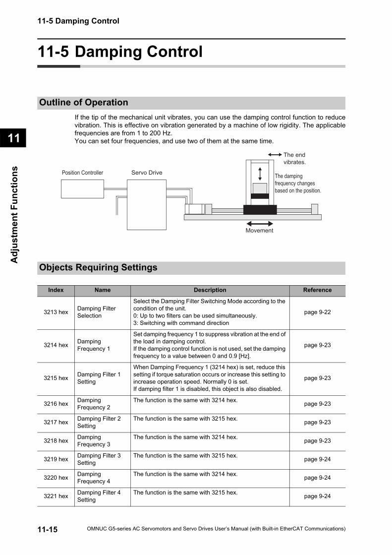
11-5 Damping Control
11
Adj
ustm
ent F
unct
ions
11-5 Damping Control
Outline of OperationIf the tip of the mechanical unit vibrates, you can use the damping control function to reducevibration. This is effective on vibration generated by a machine of low rigidity. The applicablefrequencies are from 1 to 200 Hz.You can set four frequencies, and use two of them at the same time.
Objects Requiring Settings
Position Controller Servo Drive
The endvibrates.
The dampingfrequency changesbased on the position.
Movement
Index Name Description Reference
3213 hex Damping Filter Selection
Select the Damping Filter Switching Mode according to the condition of the unit.0: Up to two filters can be used simultaneously.3: Switching with command direction
page 9-22
3214 hex Damping Frequency 1
Set damping frequency 1 to suppress vibration at the end of the load in damping control.If the damping control function is not used, set the damping frequency to a value between 0 and 0.9 [Hz].
page 9-23
3215 hex Damping Filter 1 Setting
When Damping Frequency 1 (3214 hex) is set, reduce this setting if torque saturation occurs or increase this setting to increase operation speed. Normally 0 is set.If damping filter 1 is disabled, this object is also disabled.
page 9-23
3216 hex Damping Frequency 2
The function is the same with 3214 hex. page 9-23
3217 hex Damping Filter 2 Setting
The function is the same with 3215 hex. page 9-23
3218 hex Damping Frequency 3
The function is the same with 3214 hex. page 9-23
3219 hex Damping Filter 3 Setting
The function is the same with 3215 hex. page 9-24
3220 hex Damping Frequency 4
The function is the same with 3214 hex. page 9-24
3221 hex Damping Filter 4 Setting
The function is the same with 3215 hex. page 9-24
11-15 OMNUC G5-series AC Servomotors and Servo Drives User’s Manual (with Built-in EtherCAT Communications)
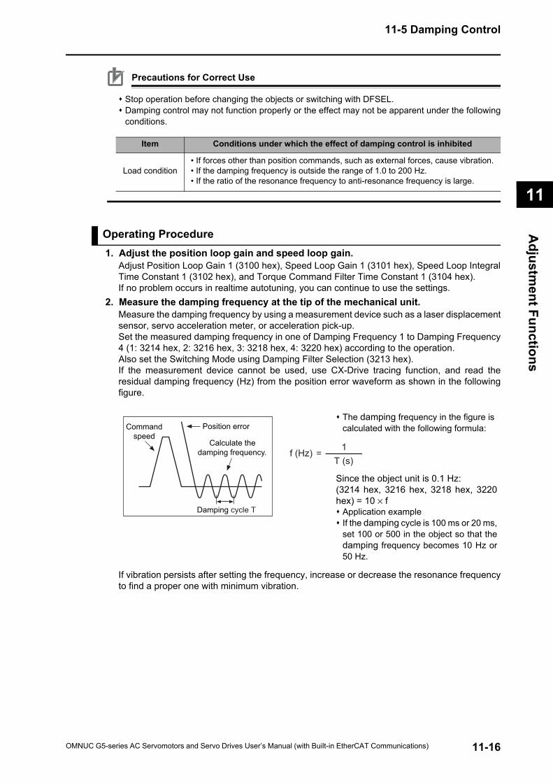
11-5 Damping Control
11
Adjustm
ent Functions
Precautions for Correct Use
Stop operation before changing the objects or switching with DFSEL.Damping control may not function properly or the effect may not be apparent under the followingconditions.
Operating Procedure1. Adjust the position loop gain and speed loop gain.
Adjust Position Loop Gain 1 (3100 hex), Speed Loop Gain 1 (3101 hex), Speed Loop IntegralTime Constant 1 (3102 hex), and Torque Command Filter Time Constant 1 (3104 hex).If no problem occurs in realtime autotuning, you can continue to use the settings.
2. Measure the damping frequency at the tip of the mechanical unit.Measure the damping frequency by using a measurement device such as a laser displacementsensor, servo acceleration meter, or acceleration pick-up.Set the measured damping frequency in one of Damping Frequency 1 to Damping Frequency4 (1: 3214 hex, 2: 3216 hex, 3: 3218 hex, 4: 3220 hex) according to the operation.Also set the Switching Mode using Damping Filter Selection (3213 hex).If the measurement device cannot be used, use CX-Drive tracing function, and read theresidual damping frequency (Hz) from the position error waveform as shown in the followingfigure.
If vibration persists after setting the frequency, increase or decrease the resonance frequencyto find a proper one with minimum vibration.
Item Conditions under which the effect of damping control is inhibited
Load condition• If forces other than position commands, such as external forces, cause vibration.• If the damping frequency is outside the range of 1.0 to 200 Hz.• If the ratio of the resonance frequency to anti-resonance frequency is large.
The damping frequency in the figure is calculated with the following formula:
Since the object unit is 0.1 Hz:(3214 hex, 3216 hex, 3218 hex, 3220hex) = 10 × f
Application exampleIf the damping cycle is 100 ms or 20 ms,set 100 or 500 in the object so that thedamping frequency becomes 10 Hz or50 Hz.
Commandspeed
Position error
Calculate thedamping frequency.
Damping cycle T
1T (s)
f (Hz) =
11-16OMNUC G5-series AC Servomotors and Servo Drives User’s Manual (with Built-in EtherCAT Communications)
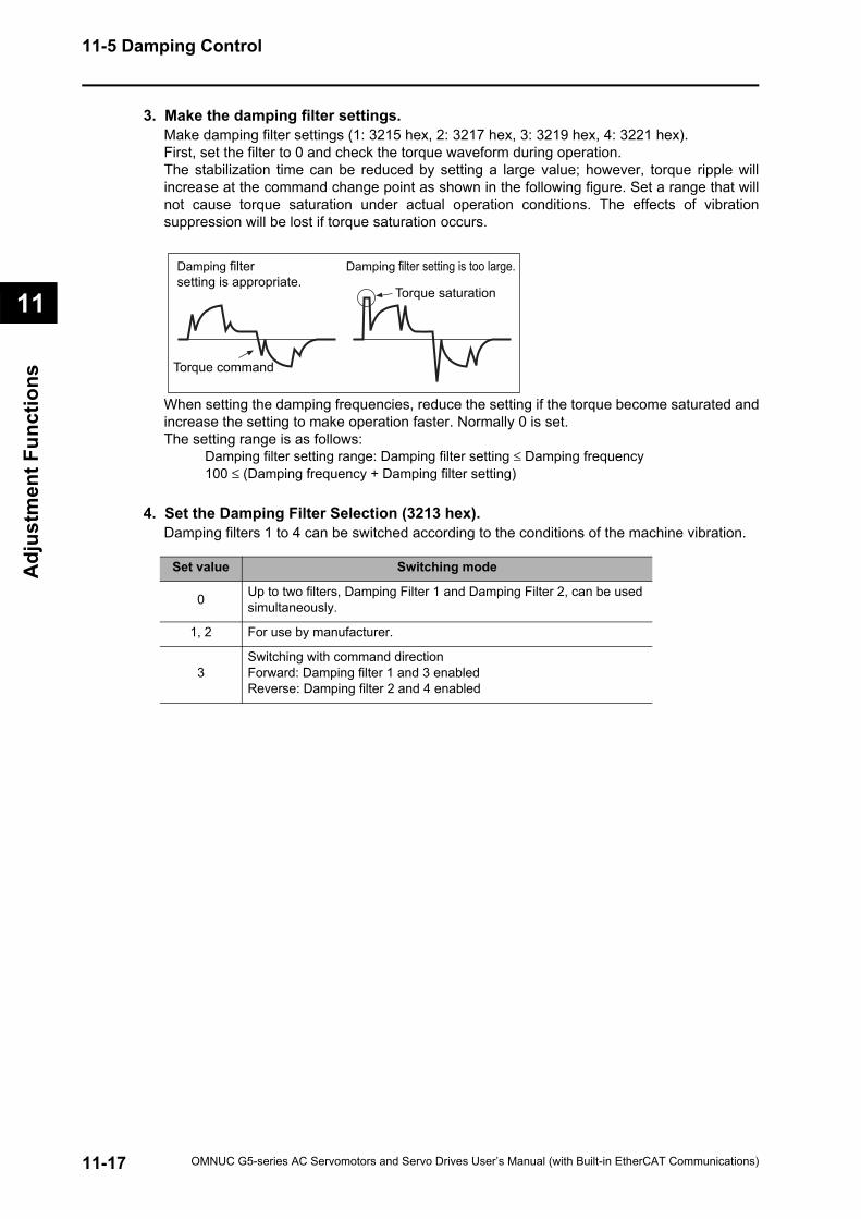
11-5 Damping Control
11
Adj
ustm
ent F
unct
ions
3. Make the damping filter settings.Make damping filter settings (1: 3215 hex, 2: 3217 hex, 3: 3219 hex, 4: 3221 hex).First, set the filter to 0 and check the torque waveform during operation. The stabilization time can be reduced by setting a large value; however, torque ripple willincrease at the command change point as shown in the following figure. Set a range that willnot cause torque saturation under actual operation conditions. The effects of vibrationsuppression will be lost if torque saturation occurs.
When setting the damping frequencies, reduce the setting if the torque become saturated andincrease the setting to make operation faster. Normally 0 is set.The setting range is as follows:
Damping filter setting range: Damping filter setting ≤ Damping frequency100 ≤ (Damping frequency + Damping filter setting)
4. Set the Damping Filter Selection (3213 hex).Damping filters 1 to 4 can be switched according to the conditions of the machine vibration.
Set value Switching mode
0 Up to two filters, Damping Filter 1 and Damping Filter 2, can be used simultaneously.
1, 2 For use by manufacturer.
3Switching with command directionForward: Damping filter 1 and 3 enabledReverse: Damping filter 2 and 4 enabled
Torque command
Torque saturation
Damping filter setting is too large.Damping filtersetting is appropriate.
11-17 OMNUC G5-series AC Servomotors and Servo Drives User’s Manual (with Built-in EtherCAT Communications)
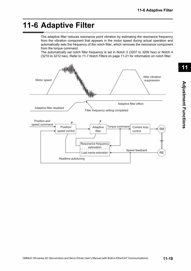
11-6 Adaptive Filter
11
Adjustm
ent Functions
11-6 Adaptive FilterThe adaptive filter reduces resonance point vibration by estimating the resonance frequencyfrom the vibration component that appears in the motor speed during actual operation andautomatically sets the frequency of the notch filter, which removes the resonance componentfrom the torque command.The automatically set notch filter frequency is set in Notch 3 (3207 to 3209 hex) or Notch 4(3210 to 3212 hex). Refer to 11-7 Notch Filters on page 11-21 for information on notch filter.
Motor speedAfter vibrationsuppression
Adaptive filter disabledAdaptive filter effect
Filter frequency setting completed
Position andspeed command
Speed feedback
Position/speed control
Realtime autotuning
Resonance frequencyestimation
Load inertia estimation
Adaptivefilter
Current loopcontrol
Torque commandSM
RE
11-18OMNUC G5-series AC Servomotors and Servo Drives User’s Manual (with Built-in EtherCAT Communications)
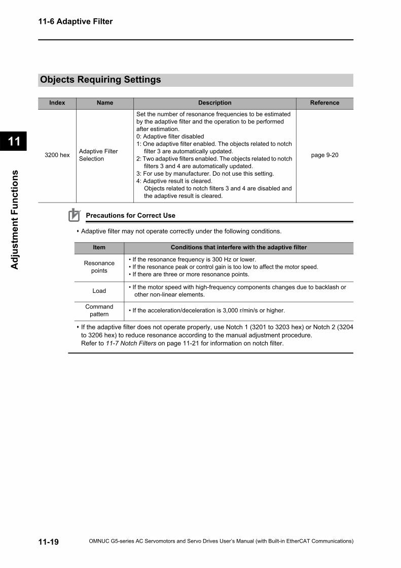
11-6 Adaptive Filter
11
Adj
ustm
ent F
unct
ions
Objects Requiring Settings
Precautions for Correct Use
Adaptive filter may not operate correctly under the following conditions.
If the adaptive filter does not operate properly, use Notch 1 (3201 to 3203 hex) or Notch 2 (3204to 3206 hex) to reduce resonance according to the manual adjustment procedure.Refer to 11-7 Notch Filters on page 11-21 for information on notch filter.
Index Name Description Reference
3200 hex Adaptive Filter Selection
Set the number of resonance frequencies to be estimated by the adaptive filter and the operation to be performed after estimation.0: Adaptive filter disabled1: One adaptive filter enabled. The objects related to notch
filter 3 are automatically updated. 2: Two adaptive filters enabled. The objects related to notch
filters 3 and 4 are automatically updated. 3: For use by manufacturer. Do not use this setting.4: Adaptive result is cleared.
Objects related to notch filters 3 and 4 are disabled and the adaptive result is cleared.
page 9-20
Item Conditions that interfere with the adaptive filter
Resonance points
• If the resonance frequency is 300 Hz or lower.• If the resonance peak or control gain is too low to affect the motor speed.• If there are three or more resonance points.
Load • If the motor speed with high-frequency components changes due to backlash or other non-linear elements.
Command pattern • If the acceleration/deceleration is 3,000 r/min/s or higher.
11-19 OMNUC G5-series AC Servomotors and Servo Drives User’s Manual (with Built-in EtherCAT Communications)
11-6 Adaptive Filter
11
Adjustm
ent Functions
Operating Procedure1. Set the Adaptive Filter Selection (3200 hex).
Select adaptive filter 1 or 2 in the Adaptive Filter Selection (3200 hex).2. Start actual operation.
Enter an operation command and start the actual operation.3. The Notch Filters 3 and 4 are automatically set.
When the influence of a resonance point appears in the motor speed, the Notch Filters 3 and4 objects are set automatically according to the number of adaptive filters.
Precautions for Correct Use
An unusual noise or vibration may occur until the adaptive filter stabilizes after startup,immediately after the first servo ON, or when the Realtime Autotuning Machine Rigidity Selection(3003 hex) is increased. This is not a problem if it disappears right away. If the vibration or unusualnoise, however, continues for three or more reciprocating operations, take the following measuresin the possible order.
• Write the objects used during normal operation to the EEPROM.• Lower the Realtime Autotuning Machine Rigidity Setting (3003 hex).• Disable the adaptive filter by setting the Adaptive Filter Selection (3200 hex) to 0.
(Resetting of inertial estimation and adaptive operation)• Manually set the notch filter.
If unusual noise or vibration occurs, the setting of Notch 3 (3207 to 3209 hex) or Notch 4 (3210 to3212 hex) may have changed to an extreme value. In this case, set Adaptive Filter Selection (3200hex) to 0 to disable the object and then set the Notch 3 Frequency Setting (3207 hex) and Notch4 Frequency Setting (3210 hex) to 5,000 (disabled). Next, enable Adaptive Filter Selection again.The Notch 3 Frequency Setting (3207 hex) and Notch 4 Frequency Setting (3210 hex) are writtento the EEPROM every 30 minutes. When the power supply is turned OFF and then turned ONagain, this data is used as the default settings to perform adaptive operation.
11-20OMNUC G5-series AC Servomotors and Servo Drives User’s Manual (with Built-in EtherCAT Communications)
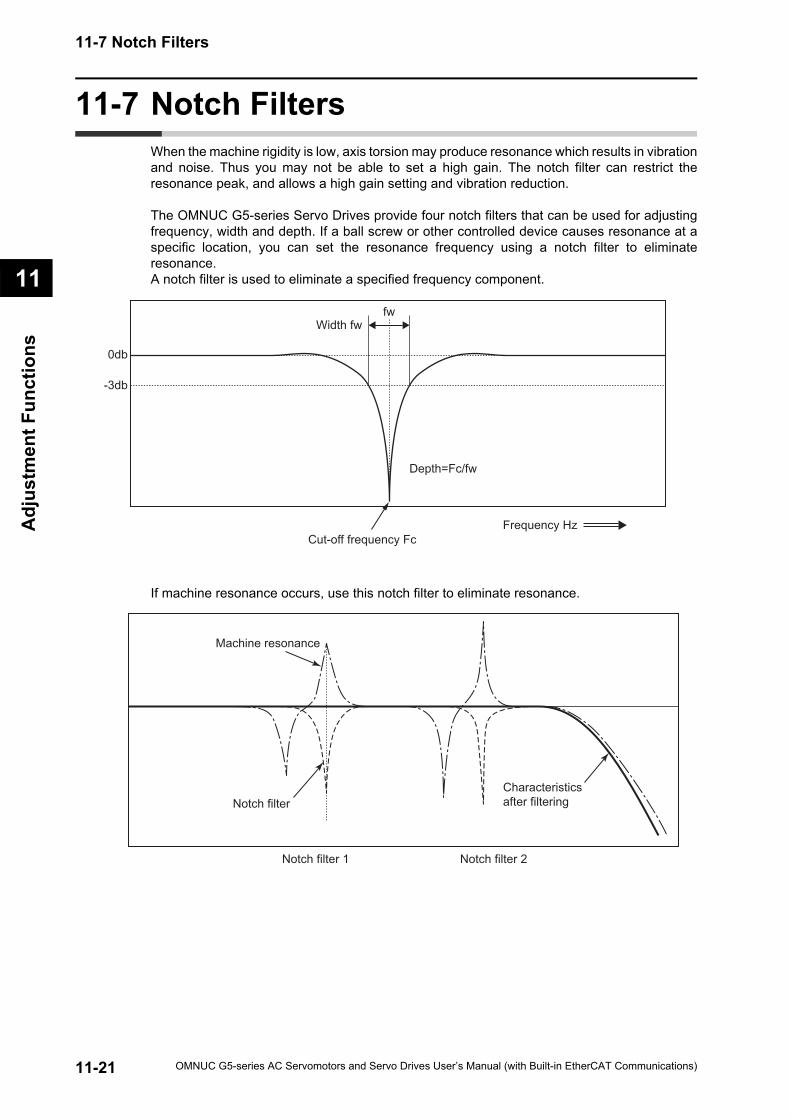
11-7 Notch Filters
11
Adj
ustm
ent F
unct
ions
11-7 Notch FiltersWhen the machine rigidity is low, axis torsion may produce resonance which results in vibrationand noise. Thus you may not be able to set a high gain. The notch filter can restrict theresonance peak, and allows a high gain setting and vibration reduction.
The OMNUC G5-series Servo Drives provide four notch filters that can be used for adjustingfrequency, width and depth. If a ball screw or other controlled device causes resonance at aspecific location, you can set the resonance frequency using a notch filter to eliminateresonance.A notch filter is used to eliminate a specified frequency component.
If machine resonance occurs, use this notch filter to eliminate resonance.
Depth=Fc/fw
Cut-off frequency FcFrequency Hz
Width fwfw
0db
-3db
Notch filter 1 Notch filter 2
Machine resonance
Notch filterCharacteristicsafter filtering
11-21 OMNUC G5-series AC Servomotors and Servo Drives User’s Manual (with Built-in EtherCAT Communications)
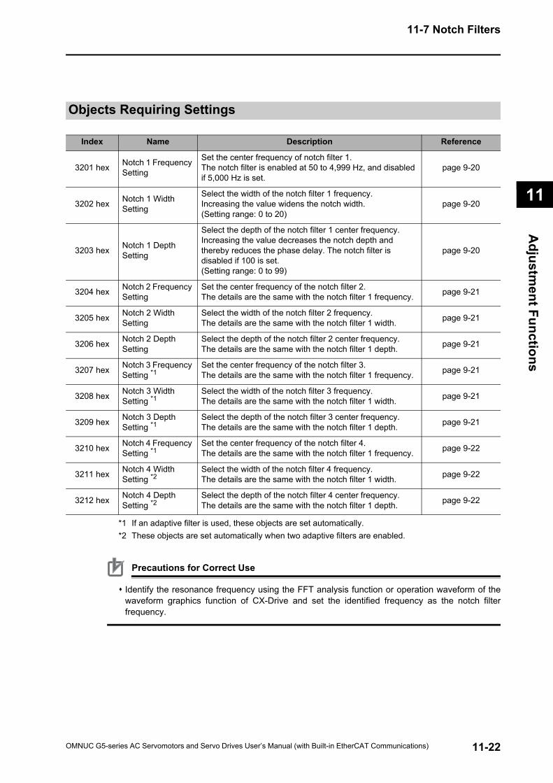
11-7 Notch Filters
11
Adjustm
ent Functions
Objects Requiring Settings
*1 If an adaptive filter is used, these objects are set automatically.*2 These objects are set automatically when two adaptive filters are enabled.
Precautions for Correct Use
Identify the resonance frequency using the FFT analysis function or operation waveform of thewaveform graphics function of CX-Drive and set the identified frequency as the notch filterfrequency.
Index Name Description Reference
3201 hex Notch 1 Frequency Setting
Set the center frequency of notch filter 1.The notch filter is enabled at 50 to 4,999 Hz, and disabled if 5,000 Hz is set.
page 9-20
3202 hex Notch 1 Width Setting
Select the width of the notch filter 1 frequency.Increasing the value widens the notch width.(Setting range: 0 to 20)
page 9-20
3203 hex Notch 1 Depth Setting
Select the depth of the notch filter 1 center frequency.Increasing the value decreases the notch depth and thereby reduces the phase delay. The notch filter is disabled if 100 is set.(Setting range: 0 to 99)
page 9-20
3204 hex Notch 2 Frequency Setting
Set the center frequency of the notch filter 2.The details are the same with the notch filter 1 frequency. page 9-21
3205 hex Notch 2 Width Setting
Select the width of the notch filter 2 frequency.The details are the same with the notch filter 1 width. page 9-21
3206 hex Notch 2 Depth Setting
Select the depth of the notch filter 2 center frequency.The details are the same with the notch filter 1 depth. page 9-21
3207 hex Notch 3 Frequency Setting *1
Set the center frequency of the notch filter 3.The details are the same with the notch filter 1 frequency. page 9-21
3208 hex Notch 3 Width Setting *1
Select the width of the notch filter 3 frequency.The details are the same with the notch filter 1 width. page 9-21
3209 hex Notch 3 Depth Setting *1
Select the depth of the notch filter 3 center frequency.The details are the same with the notch filter 1 depth. page 9-21
3210 hex Notch 4 Frequency Setting *1
Set the center frequency of the notch filter 4.The details are the same with the notch filter 1 frequency. page 9-22
3211 hex Notch 4 Width Setting *2
Select the width of the notch filter 4 frequency.The details are the same with the notch filter 1 width. page 9-22
3212 hex Notch 4 Depth Setting *2
Select the depth of the notch filter 4 center frequency.The details are the same with the notch filter 1 depth. page 9-22
11-22OMNUC G5-series AC Servomotors and Servo Drives User’s Manual (with Built-in EtherCAT Communications)
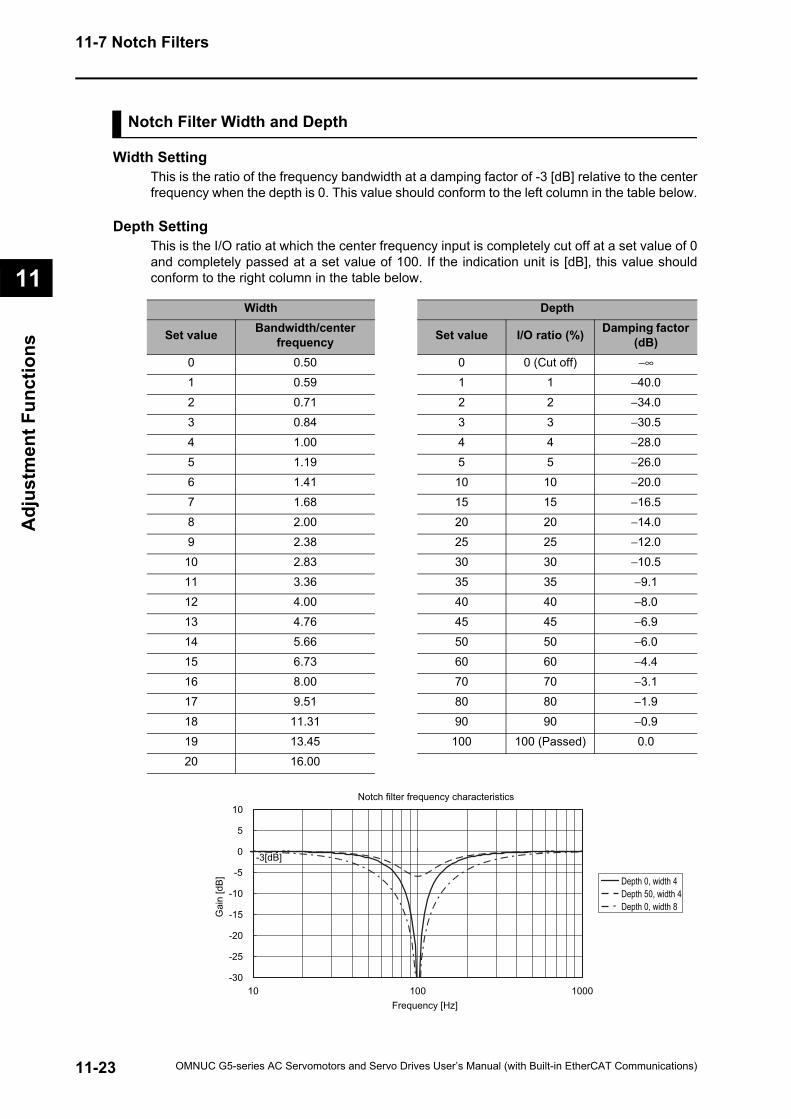
11-7 Notch Filters
11
Adj
ustm
ent F
unct
ions
Notch Filter Width and Depth
Width SettingThis is the ratio of the frequency bandwidth at a damping factor of -3 [dB] relative to the centerfrequency when the depth is 0. This value should conform to the left column in the table below.
Depth SettingThis is the I/O ratio at which the center frequency input is completely cut off at a set value of 0and completely passed at a set value of 100. If the indication unit is [dB], this value shouldconform to the right column in the table below.
Width Depth
Set value Bandwidth/center frequency Set value I/O ratio (%) Damping factor
(dB)0 0.50 0 0 (Cut off) −∞
1 0.59 1 1 −40.0
2 0.71 2 2 −34.0
3 0.84 3 3 −30.5
4 1.00 4 4 −28.0
5 1.19 5 5 −26.0
6 1.41 10 10 −20.0
7 1.68 15 15 −16.5
8 2.00 20 20 −14.0
9 2.38 25 25 −12.0
10 2.83 30 30 −10.5
11 3.36 35 35 −9.1
12 4.00 40 40 −8.0
13 4.76 45 45 −6.9
14 5.66 50 50 −6.0
15 6.73 60 60 −4.4
16 8.00 70 70 −3.1
17 9.51 80 80 −1.9
18 11.31 90 90 −0.9
19 13.45 100 100 (Passed) 0.0
20 16.00
Notch filter frequency characteristics
-30
-25
-20
-15
-10
-5
0
5
10
000100101Frequency [Hz]
Gai
n [d
B]
-3[dB]
Depth 0, width 4Depth 50, width 4Depth 0, width 8
11-23 OMNUC G5-series AC Servomotors and Servo Drives User’s Manual (with Built-in EtherCAT Communications)
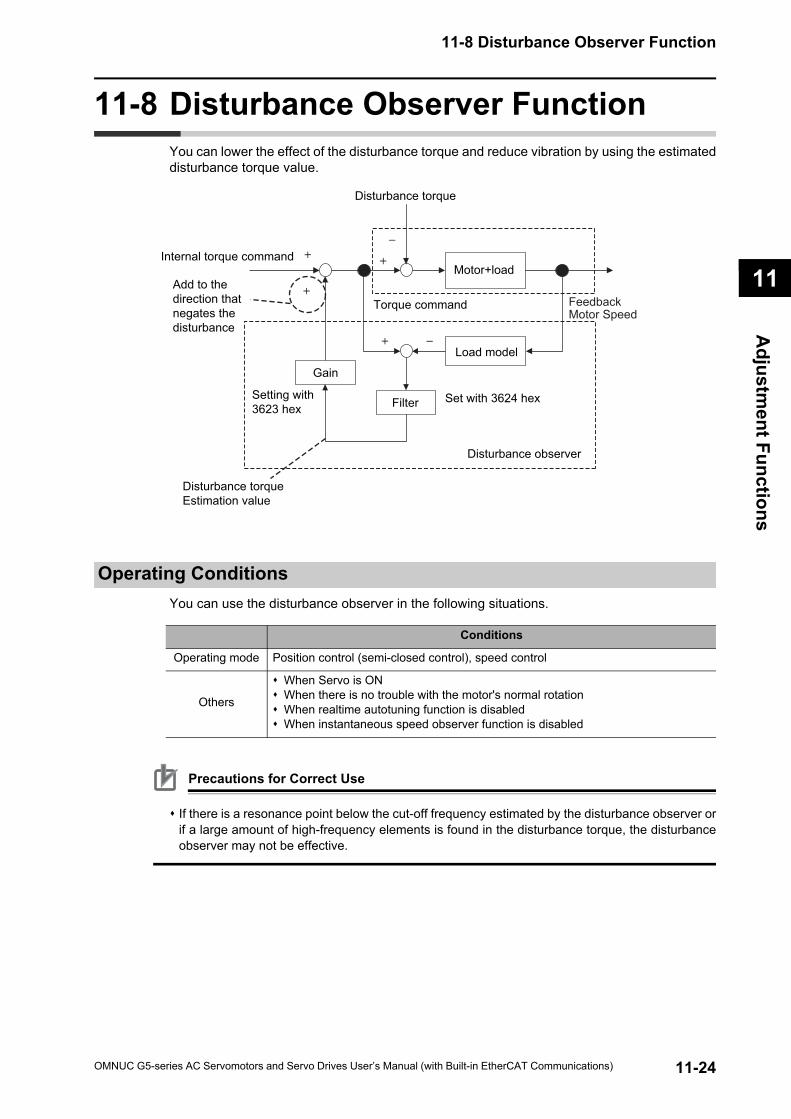
11-8 Disturbance Observer Function
11
Adjustm
ent Functions
11-8 Disturbance Observer FunctionYou can lower the effect of the disturbance torque and reduce vibration by using the estimateddisturbance torque value.
Operating ConditionsYou can use the disturbance observer in the following situations.
Precautions for Correct Use
If there is a resonance point below the cut-off frequency estimated by the disturbance observer orif a large amount of high-frequency elements is found in the disturbance torque, the disturbanceobserver may not be effective.
Conditions
Operating mode Position control (semi-closed control), speed control
Others
When Servo is ONWhen there is no trouble with the motor's normal rotationWhen realtime autotuning function is disabledWhen instantaneous speed observer function is disabled
Motor+load+
−
Load model+ −
Filter
Gain
+
+
Disturbance observer
Add to thedirection thatnegates thedisturbance
Setting with3623 hex
Set with 3624 hex
Disturbance torqueEstimation value
Disturbance torque
Torque command
Internal torque command
Feedback Motor Speed
11-24OMNUC G5-series AC Servomotors and Servo Drives User’s Manual (with Built-in EtherCAT Communications)
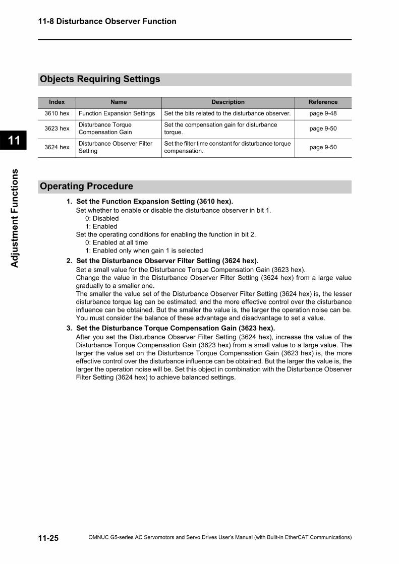
11-8 Disturbance Observer Function
11
Adj
ustm
ent F
unct
ions
Objects Requiring Settings
Operating Procedure1. Set the Function Expansion Setting (3610 hex).
Set whether to enable or disable the disturbance observer in bit 1. 0: Disabled 1: EnabledSet the operating conditions for enabling the function in bit 2. 0: Enabled at all time 1: Enabled only when gain 1 is selected
2. Set the Disturbance Observer Filter Setting (3624 hex).Set a small value for the Disturbance Torque Compensation Gain (3623 hex).Change the value in the Disturbance Observer Filter Setting (3624 hex) from a large valuegradually to a smaller one.The smaller the value set of the Disturbance Observer Filter Setting (3624 hex) is, the lesserdisturbance torque lag can be estimated, and the more effective control over the disturbanceinfluence can be obtained. But the smaller the value is, the larger the operation noise can be.You must consider the balance of these advantage and disadvantage to set a value.
3. Set the Disturbance Torque Compensation Gain (3623 hex).After you set the Disturbance Observer Filter Setting (3624 hex), increase the value of theDisturbance Torque Compensation Gain (3623 hex) from a small value to a large value. Thelarger the value set on the Disturbance Torque Compensation Gain (3623 hex) is, the moreeffective control over the disturbance influence can be obtained. But the larger the value is, thelarger the operation noise will be. Set this object in combination with the Disturbance ObserverFilter Setting (3624 hex) to achieve balanced settings.
Index Name Description Reference
3610 hex Function Expansion Settings Set the bits related to the disturbance observer. page 9-48
3623 hex Disturbance Torque Compensation Gain
Set the compensation gain for disturbance torque. page 9-50
3624 hex Disturbance Observer Filter Setting
Set the filter time constant for disturbance torque compensation. page 9-50
11-25 OMNUC G5-series AC Servomotors and Servo Drives User’s Manual (with Built-in EtherCAT Communications)
11-9 Friction Torque Compensation Function
11
Adjustm
ent Functions
11-9 Friction Torque Compensation FunctionTwo types of friction torque compensations can be set to reduce the influence of mechanicalfrictions. One is the unbalanced load compensation that offsets the constantly appliedunbalance torque. The other is the dynamic friction compensation that changes the offsetdirection in accordance with the operating direction.
Operating ConditionsYou can use the function under the following conditions:
Objects Requiring SettingsThe torque compensation function needs the combined settings of following three objects.
Conditions
When Servo is ONWhen there is no trouble with the motor's normal rotationWhen realtime autotuning function is disabledWhen instantaneous speed observer function is disabled
Index Name Description Reference
3607 hex Torque Command Value Offset
Set the unbalanced load compensation value that is always added to the internal torque command in the control mode other than torque control.
page 9-47
3608 hex Forward Direction Torque Offset
Set the dynamic friction compensation value that is added to the internal torque command when a forward position command is input for position control or fully-closed control.
page 9-47
3609 hex Reverse Direction Torque Offset
Set the dynamic friction compensation value that is added to the internal torque command when a reverse position command is input for position control or fully-closed control.
page 9-47
11-26OMNUC G5-series AC Servomotors and Servo Drives User’s Manual (with Built-in EtherCAT Communications)
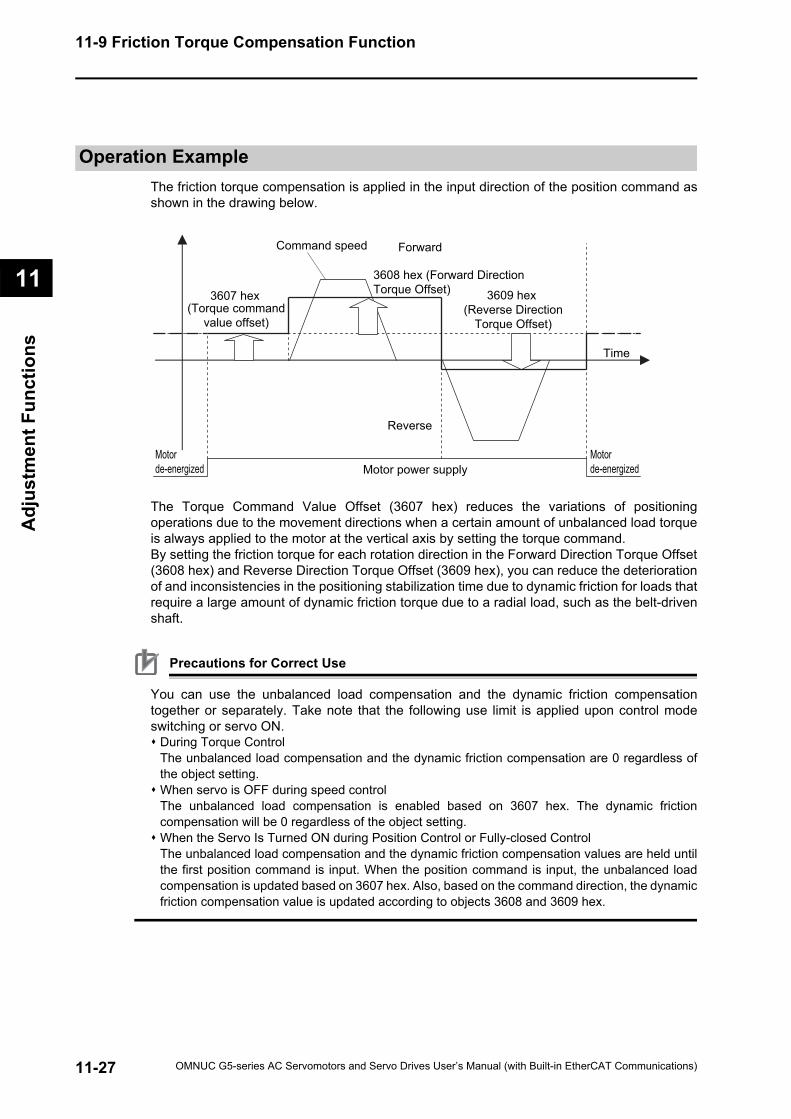
11-9 Friction Torque Compensation Function
11
Adj
ustm
ent F
unct
ions
Operation ExampleThe friction torque compensation is applied in the input direction of the position command asshown in the drawing below.
The Torque Command Value Offset (3607 hex) reduces the variations of positioningoperations due to the movement directions when a certain amount of unbalanced load torqueis always applied to the motor at the vertical axis by setting the torque command.By setting the friction torque for each rotation direction in the Forward Direction Torque Offset(3608 hex) and Reverse Direction Torque Offset (3609 hex), you can reduce the deteriorationof and inconsistencies in the positioning stabilization time due to dynamic friction for loads thatrequire a large amount of dynamic friction torque due to a radial load, such as the belt-drivenshaft.
Precautions for Correct Use
You can use the unbalanced load compensation and the dynamic friction compensationtogether or separately. Take note that the following use limit is applied upon control modeswitching or servo ON.
During Torque ControlThe unbalanced load compensation and the dynamic friction compensation are 0 regardless ofthe object setting.When servo is OFF during speed controlThe unbalanced load compensation is enabled based on 3607 hex. The dynamic frictioncompensation will be 0 regardless of the object setting.When the Servo Is Turned ON during Position Control or Fully-closed ControlThe unbalanced load compensation and the dynamic friction compensation values are held untilthe first position command is input. When the position command is input, the unbalanced loadcompensation is updated based on 3607 hex. Also, based on the command direction, the dynamicfriction compensation value is updated according to objects 3608 and 3609 hex.
Command speed
Time
Motorde-energized
Motorde-energized Motor power supply
3607 hex(Torque command
value offset)
Forward
Reverse
3608 hex (Forward Direction Torque Offset) 3609 hex
(Reverse DirectionTorque Offset)
11-27 OMNUC G5-series AC Servomotors and Servo Drives User’s Manual (with Built-in EtherCAT Communications)
11-10 Hybrid Vibration Suppression Function
11
Adjustm
ent Functions
11-10 Hybrid Vibration Suppression FunctionThis function suppresses the vibration that is caused by the amount of the torsion between themotor and the load in the Fully-closed Control Mode. You can use this function to increase thegain setting.
Operating ConditionsThe hybrid vibration suppression function can be used in the following situations.
Objects Requiring Settings
Operating Procedure1. Set the Hybrid Vibration Suppression Gain (3634 hex) to the same value as the
position loop gain.2. Gradually increase the set value of the Hybrid Vibration Suppression Filter (3635
hex) while driving with fully-closed control and check the changes in the response.If the response improves, find the combination of 3634 hex and 3635 hex that result in theoptimal response by adjusting them.
Precautions for Correct Use
This function is effective when the amount of torsion between the motor shaft and the load is large.It may be less effective when the amount of torsion is small.
Conditions
Operating mode Fully-closed Control mode
Others
When Servo is ONWhen there is no trouble with the motor's normal rotationWhen realtime autotuning function is disabledWhen instantaneous speed observer function is disabled
Index Name Description Reference
3634 hex
Hybrid Vibration Suppression Gain
Set the hybrid vibration suppression gain.In general, set it to the same value as the position loop gain, and finely adjust it based on the situation.
page 9-52
3635 hex Hybrid Vibration Suppression Filter
Set the hybrid vibration suppression filter. page 9-52
11-28OMNUC G5-series AC Servomotors and Servo Drives User’s Manual (with Built-in EtherCAT Communications)
11-11 Feed-forward Function
11
Adj
ustm
ent F
unct
ions
11-11 Feed-forward FunctionThe feed-forward function come in 2 types: speed feed-forward and torque feed-forward.The speed feed-forward can minimize the position error and increase the responsivenessduring position or fully-closed control.Responsiveness is improved by adding the speed feed-forward value calculated from theinternal position command and related objects (3110 hex and 3111 hex) to the speedcommand calculated by comparing the internal position command and the position feedback. If the Velocity offset (60B1 hex) is set, both the set value and the speed feed-forward valuedare added to the Control effort (60FA hex). The torque feed-forward can increase the responsiveness of the speed control system. Responsiveness is improved by adding the torque feed-forward value calculated from theControl effort (60FA hex) and related objects (3112 hex and 3113 hex) to the torque commandcalculated by comparing the Control effort (60FA hex) and the speed feedback. If the Torque offset (60B2 hex) is set, both the set value and the torque feed-forward valuedare added to the torque command.
Objects Requiring Settings
Index Name Description Reference
3110 hex Speed Feed-forward Gain
The speed command from position control processing is added to the product of the Control effort (60FA hex) that is calculated from the internal position command times the ratio in this object.
page 9-10
3111 hex Speed Feed-forward Command Filter
Set the time constant for the first-order lag filter that is applied to speed feed-forward input. page 9-11
3112 hex Torque Feed-forward GainThe torque command from speed control processing is added to the product of the Control effort (60FA hex) times the ratio in this object.
page 9-11
3113 hex Torque Feed-forward Command Filter
Set the time constant for the first-order lag filter that is applied to torque feed-forward input. page 9-11
60B1 hex Velocity offset Set the offset for the speed command. It will be added to the Control effort (60FA hex). page A-55
60B2 hex Torque offset Set the offset for the torque command. It will be added to the torque command value. page A-55
11-29 OMNUC G5-series AC Servomotors and Servo Drives User’s Manual (with Built-in EtherCAT Communications)

11-11 Feed-forward Function
11
Adjustm
ent Functions
Operating Procedure
Speed Feed-forward Operating Method1. Set the Speed Feed-forward Command Filter (3111 hex).
Set it to approx. 50 (0.5 ms).2. Adjust the Speed Feed-forward Gain (3110 hex).
Gradually increase the value of the Speed Feed-forward Gain (3110 hex) and finely adjust itto avoid overshooting during acceleration/deceleration.If the speed feed-forward gain is set to 100%, the position error is calculated at 0. However,large overshooting will occur during acceleration/deceleration.
The position error during an operation at a certain speed will decrease based on the followingformula according to the speed feed-forward gain value.
The position error in the range of constant speed becomes smaller as the speed feed-forwardgain increases.
Precautions for Correct Use
If the updating cycle of the position command input is longer than the Servo Drive control cycle,or if the input command frequency is not uniform, the operating noise may increase while thespeed feed-forward is enabled. Apply the position command filter (first-order lag or FIRsmoothing) or increase the speed feed-forward filter setting.
Position error [command units] = Command speed [command units/s]/Position loop gain [1/s] × (100 - Speed feed-forward gain [%])/100
Commandspeed
Motor speed
Position errorSpeed FF gain
50 [%]
80 [%]
0 [%]
Time
11-30OMNUC G5-series AC Servomotors and Servo Drives User’s Manual (with Built-in EtherCAT Communications)
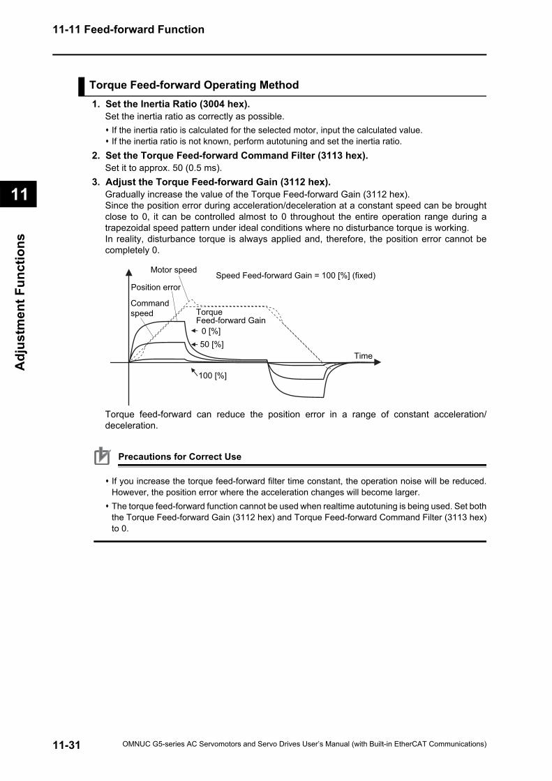
11-11 Feed-forward Function
11
Adj
ustm
ent F
unct
ions
Torque Feed-forward Operating Method1. Set the Inertia Ratio (3004 hex).
Set the inertia ratio as correctly as possible.If the inertia ratio is calculated for the selected motor, input the calculated value.If the inertia ratio is not known, perform autotuning and set the inertia ratio.
2. Set the Torque Feed-forward Command Filter (3113 hex).Set it to approx. 50 (0.5 ms).
3. Adjust the Torque Feed-forward Gain (3112 hex).Gradually increase the value of the Torque Feed-forward Gain (3112 hex).Since the position error during acceleration/deceleration at a constant speed can be broughtclose to 0, it can be controlled almost to 0 throughout the entire operation range during atrapezoidal speed pattern under ideal conditions where no disturbance torque is working.In reality, disturbance torque is always applied and, therefore, the position error cannot becompletely 0.
Torque feed-forward can reduce the position error in a range of constant acceleration/deceleration.
Precautions for Correct Use
If you increase the torque feed-forward filter time constant, the operation noise will be reduced.However, the position error where the acceleration changes will become larger.The torque feed-forward function cannot be used when realtime autotuning is being used. Set boththe Torque Feed-forward Gain (3112 hex) and Torque Feed-forward Command Filter (3113 hex)to 0.
Commandspeed
Motor speed
Position errorSpeed Feed-forward Gain = 100 [%] (fixed)
100 [%]
0 [%]
Torque Feed-forward Gain
50 [%]Time
11-31 OMNUC G5-series AC Servomotors and Servo Drives User’s Manual (with Built-in EtherCAT Communications)
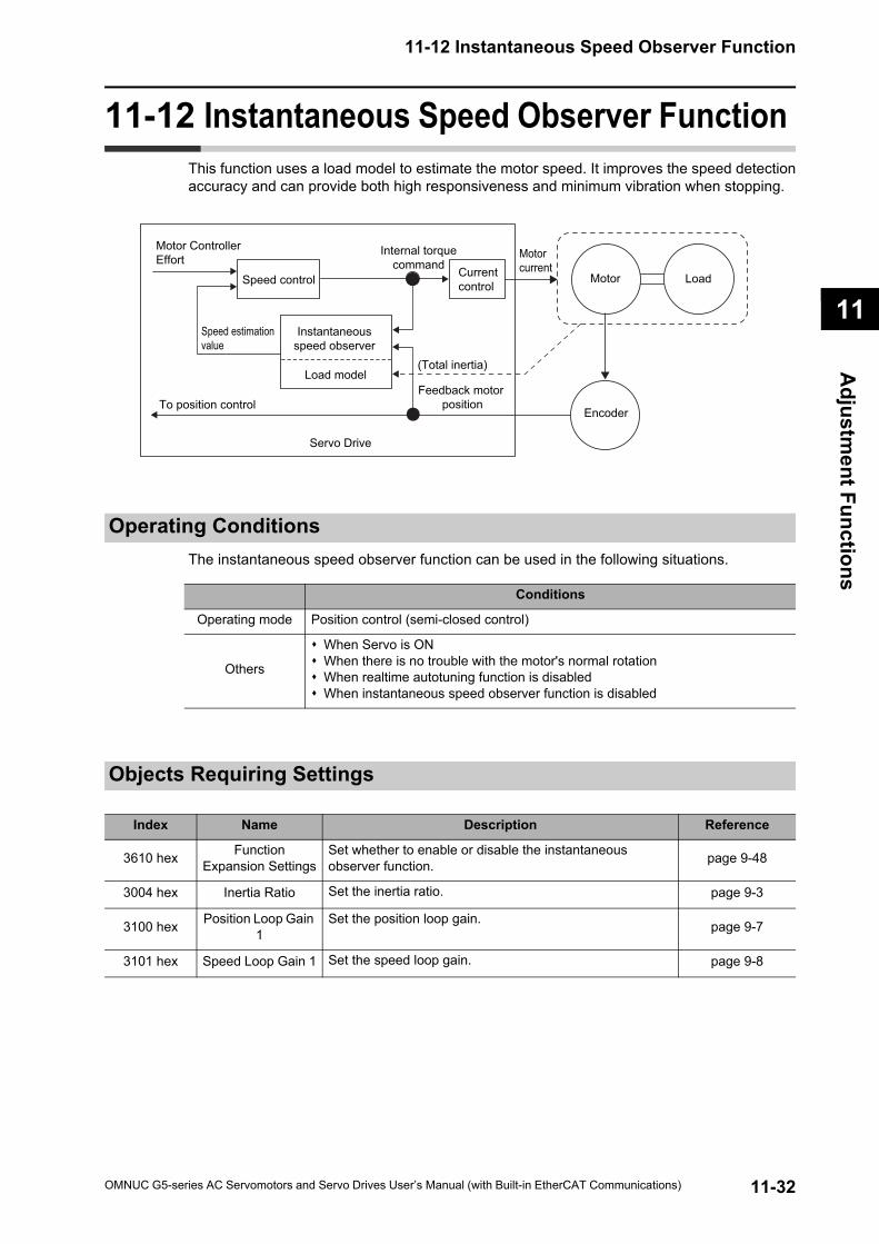
11-12 Instantaneous Speed Observer Function
11
Adjustm
ent Functions
11-12 Instantaneous Speed Observer FunctionThis function uses a load model to estimate the motor speed. It improves the speed detectionaccuracy and can provide both high responsiveness and minimum vibration when stopping.
Operating ConditionsThe instantaneous speed observer function can be used in the following situations.
Objects Requiring Settings
CurrentcontrolSpeed control
Speed estimationvalue
Internal torque command
Instantaneousspeed observer
Load model
Motorcurrent
Motor
Encoder
Servo Drive
Feedback motor positionTo position control
Load
(Total inertia)
Motor Controller Effort
Conditions
Operating mode Position control (semi-closed control)
Others
When Servo is ONWhen there is no trouble with the motor's normal rotationWhen realtime autotuning function is disabledWhen instantaneous speed observer function is disabled
Index Name Description Reference
3610 hex Function Expansion Settings
Set whether to enable or disable the instantaneous observer function. page 9-48
3004 hex Inertia Ratio Set the inertia ratio. page 9-3
3100 hex Position Loop Gain 1
Set the position loop gain. page 9-7
3101 hex Speed Loop Gain 1 Set the speed loop gain. page 9-8
11-32OMNUC G5-series AC Servomotors and Servo Drives User’s Manual (with Built-in EtherCAT Communications)
11-12 Instantaneous Speed Observer Function
11
Adj
ustm
ent F
unct
ions
Operating Procedure1. Set the Inertia Ratio (3004 hex).
Set the inertia ratio as correctly as possible.If the Inertia Ratio (3004 hex) is obtained in realtime auto gain tuning, use the set value.If the inertia ratio is calculated for the selected motor, input the calculated value.If the inertia ratio is not known, perform autotuning and set the inertia ratio.
2. Adjust the position loop gain and speed loop gain.Adjust Position Loop Gain 1 (3100 hex), Speed Loop Gain 1 (3101 hex), Speed Loop IntegralTime Constant 1 (3102 hex), and Torque Command Filter Time Constant 1 (3104 hex).If no problem occurs in realtime autotuning, you can continue to use the settings.
3. Set the Function Expansion Setting (3610 hex).Set whether to enable or disable the instantaneous speed observer function in bit 0.If you set this to 1 (enabled), the speed detection method switches to instantaneous speedobserver.
If the machine operation noise or vibration increases, or fluctuations in the torque monitorwaveform increase significant enough to cause a problem, return the setting to 0 and make surethat the inertia ratio or the adjustment objects are correct.If the machine operation noise or vibration decreases, or fluctuations in the torque monitorwaveform decrease, make small adjustments to the Inertia Ratio (3004 hex) to find the setting thatmakes the smallest fluctuations while monitoring the position error waveform and the actual speedwaveform.If Position Loop Gain 1 (3100 hex), Speed Loop Gain 1 (3101 hex), or Speed Loop Integral TimeConstant 1 (3102 hex) is changed, the optimal value for the Inertia Ratio (3004 hex) may change,so make small adjustments to the value of the Inertia Ratio (3004 hex) again to set a value thatmakes the smallest fluctuations.
Precautions for Correct Use
This function may not function properly or the effect may not be apparent under the followingconditions.
• If there is a large resonance point at a frequency of 300 Hz or lower.• If there is a non-linear element (play), such as a large backlash.• If the load inertia changes.• If there is a large disturbance torque with high-frequency elements applied.• If the setting range for positioning is small.
11-33 OMNUC G5-series AC Servomotors and Servo Drives User’s Manual (with Built-in EtherCAT Communications)
12
Troubleshooting and MaintenanceThis chapter describes the items to check when problems occur, troubleshootingusing the error displays, troubleshooting based on the operating conditions, andperiodic maintenance.
12-1 Troubleshooting .........................................................12-112-2 Warnings .....................................................................12-412-3 Errors ...........................................................................12-712-4 Troubleshooting .......................................................12-1312-5 Periodic Maintenance...............................................12-33
OMNUC G5-series AC Servomotors and Servo Drives User’s Manual (with Built-in EtherCAT Communications)
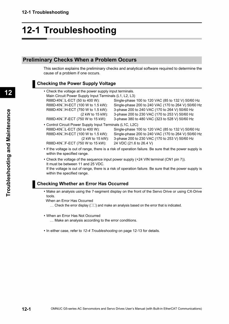
12-1 Troubleshooting
12
Trou
bles
hoot
ing
and
Mai
nten
ance
12-1 Troubleshooting
Preliminary Checks When a Problem OccursThis section explains the preliminary checks and analytical software required to determine thecause of a problem if one occurs.
Checking the Power Supply VoltageCheck the voltage at the power supply input terminals.Main Circuit Power Supply Input Terminals (L1, L2, L3)R88D-KN@L-ECT (50 to 400 W): Single-phase 100 to 120 VAC (85 to 132 V) 50/60 HzR88D-KN@H-ECT (100 W to 1.5 kW): Single-phase 200 to 240 VAC (170 to 264 V) 50/60 HzR88D-KN@H-ECT (750 W to 1.5 kW): 3-phase 200 to 240 VAC (170 to 264 V) 50/60 Hz
(2 kW to 15 kW): 3-phase 200 to 230 VAC (170 to 253 V) 50/60 HzR88D-KN@F-ECT (750 W to 15 kW): 3-phase 380 to 480 VAC (323 to 528 V) 50/60 HzControl Circuit Power Supply Input Terminals (L1C, L2C)R88D-KN@L-ECT (50 to 400 W): Single-phase 100 to 120 VAC (85 to 132 V) 50/60 HzR88D-KN@H-ECT (100 W to 1.5 kW): Single-phase 200 to 240 VAC (170 to 264 V) 50/60 Hz
(2 kW to 15 kW): 3-phase 200 to 230 VAC (170 to 253 V) 50/60 HzR88D-KN@F-ECT (750 W to 15 kW): 24 VDC (21.6 to 26.4 V) If the voltage is out of range, there is a risk of operation failure. Be sure that the power supply iswithin the specified range.Check the voltage of the sequence input power supply (+24 VIN terminal (CN1 pin 7)).It must be between 11 and 25 VDC.If the voltage is out of range, there is a risk of operation failure. Be sure that the power supply iswithin the specified range.
Checking Whether an Error Has OccurredMake an analysis using the 7-segment display on the front of the Servo Drive or using CX-Drivetools.When an Error Has Occurred … Check the error display (@@) and make an analysis based on the error that is indicated.
When an Error Has Not Occurred … Make an analysis according to the error conditions.
In either case, refer to 12-4 Troubleshooting on page 12-13 for details.
12-1 OMNUC G5-series AC Servomotors and Servo Drives User’s Manual (with Built-in EtherCAT Communications)
12-1 Troubleshooting
12
Troubleshooting and Maintenance
Precautions When a Problem OccursWhen checking and verifying I/O after a problem has occurred, the Servo Drive may suddenlystart to operate or suddenly stop, so always take the following precautions.You should assume that anything not described in this manual is not possible with this product.
PrecautionsDisconnect the wiring before checking for cable breakage. If you test conduction with the cableconnected, test results may not be accurate due to conduction via bypassing circuit.If the encoder signal is lost, the motor may run away, or an error may occur. Be sure to disconnectthe motor from the mechanical system before checking the encoder signal.When measuring the encoder output, perform the measurement based on the GND (CN1 pin 16).When an oscilloscope is used for measurement, it will not be affected by noise if measurementsare performed using the differential between CH1 and CH2.When performing tests, first check that there are no persons in the vicinity of the equipment, andthat the equipment will not be damaged even if the motor runs away. Before performing the tests,verify that you can immediately stop the machine using an immediate stop in case the machineruns out of control.
Replacing the Servomotor or Servo DriveUse the following procedure to replace the Servomotor or Servo Drive.
Replacing the Servomotor1. Replace the motor.2. Perform origin adjustment (for position control).
When the motor is replaced, the motor's origin position (phase Z) may deviate, so originadjustment must be performed. Refer to the position controller's manual for details on performing origin adjustment.
3. Set up the absolute encoder.If a motor with an absolute encoder is used, the absolute value data in the absolute encoder iscleared when the motor is replaced, so setup is again required. The multi-rotation data will bedifferent from before it was replaced, so initialize the Motion Control Unit settings.For details, refer to Absolute Encoder Setup on page 10-6.
12-2OMNUC G5-series AC Servomotors and Servo Drives User’s Manual (with Built-in EtherCAT Communications)
12-1 Troubleshooting
12
Trou
bles
hoot
ing
and
Mai
nten
ance
Replacing the Servo Drive1. Take a record of all object settings.
Use the CX-Drive or other software and take a record of the settings of all objects. 2. Replace the Servo Drive.3. Set the objects.
Use the CX-Drive or other software and set all of the objects. 4. Set up the absolute encoder.
If a motor with an absolute encoder is used, the absolute value data in the absolute encoder iscleared when the Servo Drive is replaced, so setup is again required. The multi-rotation data willbe different from before it was replaced, so initialize the Motion Control Unit settings.For details, refer to Absolute Encoder Setup on page 10-6.
12-3 OMNUC G5-series AC Servomotors and Servo Drives User’s Manual (with Built-in EtherCAT Communications)
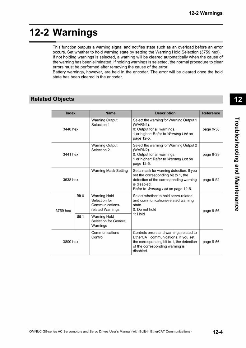
12-2 Warnings
12
Troubleshooting and Maintenance
12-2 WarningsThis function outputs a warning signal and notifies state such as an overload before an erroroccurs. Set whether to hold warning state by setting the Warning Hold Selection (3759 hex). If not holding warnings is selected, a warning will be cleared automatically when the cause ofthe warning has been eliminated. If holding warnings is selected, the normal procedure to clearerrors must be performed after removing the cause of the error. Battery warnings, however, are held in the encoder. The error will be cleared once the holdstate has been cleared in the encoder.
Related Objects
Index Name Description Reference
3440 hex
Warning Output Selection 1
Select the warning for Warning Output 1 (WARN1).0: Output for all warnings. 1 or higher: Refer to Warning List on page 12-5.
page 9-38
3441 hex
Warning Output Selection 2
Select the warning for Warning Output 2 (WARN2).0: Output for all warnings. 1 or higher: Refer to Warning List on page 12-5.
page 9-39
3638 hex
Warning Mask Setting Set a mask for warning detection. If you set the corresponding bit to 1, the detection of the corresponding warning is disabled.Refer to Warning List on page 12-5.
page 9-52
3759 hex
Bit 0 Warning Hold Selection for Communications-related Warnings
Select whether to hold servo-related and communications-related warning state. 0: Do not hold 1: Hold
page 9-56Bit 1 Warning Hold
Selection for General Warnings
3800 hex
Communications Control
Controls errors and warnings related to EtherCAT communications. If you set the corresponding bit to 1, the detection of the corresponding warning is disabled.
page 9-56
12-4OMNUC G5-series AC Servomotors and Servo Drives User’s Manual (with Built-in EtherCAT Communications)
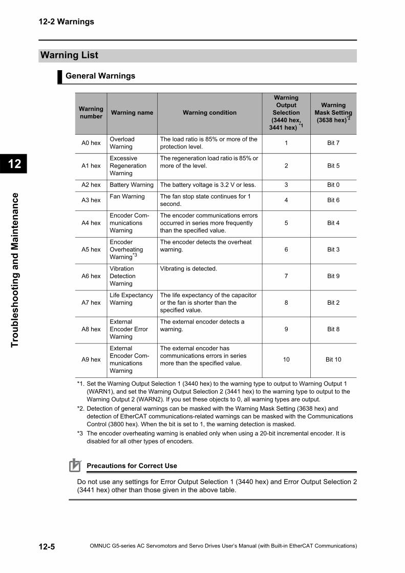
12-2 Warnings
12
Trou
bles
hoot
ing
and
Mai
nten
ance
Warning List
General Warnings
*1. Set the Warning Output Selection 1 (3440 hex) to the warning type to output to Warning Output 1 (WARN1), and set the Warning Output Selection 2 (3441 hex) to the warning type to output to the Warning Output 2 (WARN2). If you set these objects to 0, all warning types are output.
*2. Detection of general warnings can be masked with the Warning Mask Setting (3638 hex) and detection of EtherCAT communications-related warnings can be masked with the Communications Control (3800 hex). When the bit is set to 1, the warning detection is masked.
*3 The encoder overheating warning is enabled only when using a 20-bit incremental encoder. It is disabled for all other types of encoders.
Precautions for Correct Use
Do not use any settings for Error Output Selection 1 (3440 hex) and Error Output Selection 2(3441 hex) other than those given in the above table.
Warning number Warning name Warning condition
Warning Output
Selection (3440 hex,
3441 hex) *1
Warning Mask Setting (3638 hex)*2
A0 hex Overload Warning
The load ratio is 85% or more of the protection level. 1 Bit 7
A1 hexExcessive Regeneration Warning
The regeneration load ratio is 85% or more of the level. 2 Bit 5
A2 hex Battery Warning The battery voltage is 3.2 V or less. 3 Bit 0
A3 hex Fan Warning The fan stop state continues for 1 second. 4 Bit 6
A4 hexEncoder Com-munications Warning
The encoder communications errors occurred in series more frequently than the specified value.
5 Bit 4
A5 hexEncoder Overheating Warning*3
The encoder detects the overheat warning. 6 Bit 3
A6 hexVibration Detection Warning
Vibrating is detected.7 Bit 9
A7 hexLife Expectancy Warning
The life expectancy of the capacitor or the fan is shorter than the specified value.
8 Bit 2
A8 hexExternal Encoder Error Warning
The external encoder detects a warning. 9 Bit 8
A9 hex
External Encoder Com-munications Warning
The external encoder has communications errors in series more than the specified value. 10 Bit 10
12-5 OMNUC G5-series AC Servomotors and Servo Drives User’s Manual (with Built-in EtherCAT Communications)
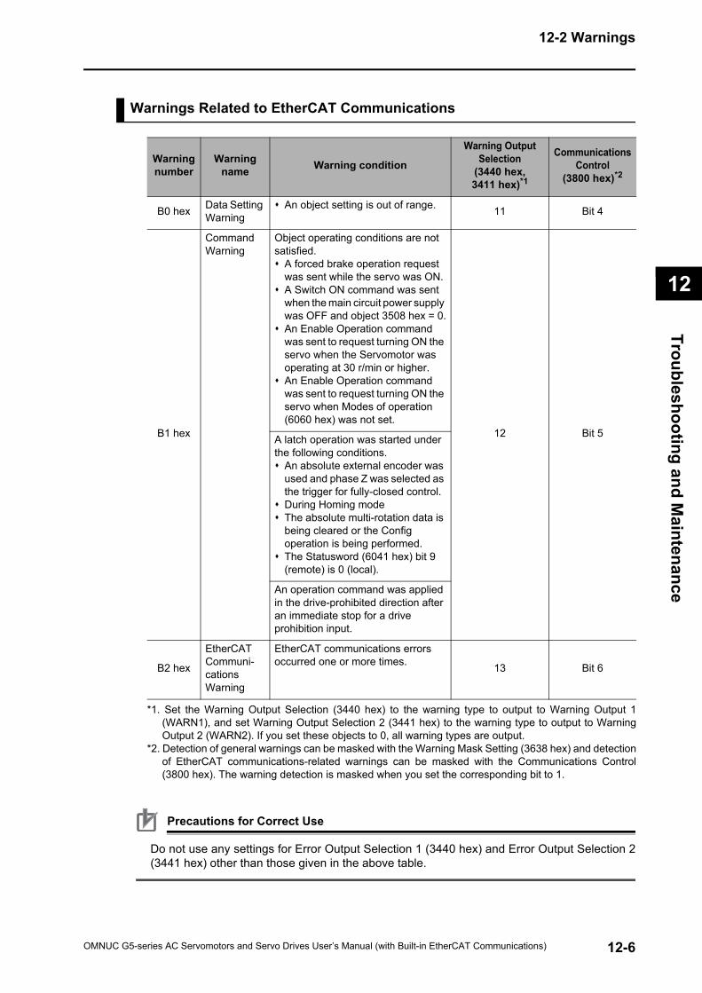
12-2 Warnings
12
Troubleshooting and Maintenance
Warnings Related to EtherCAT Communications
Precautions for Correct Use
Do not use any settings for Error Output Selection 1 (3440 hex) and Error Output Selection 2(3441 hex) other than those given in the above table.
Warning number
Warning name Warning condition
Warning Output Selection
(3440 hex, 3411 hex)*1
Communications Control
(3800 hex)*2
B0 hex Data Setting Warning
An object setting is out of range. 11 Bit 4
B1 hex
Command Warning
Object operating conditions are not satisfied.
A forced brake operation request was sent while the servo was ON. A Switch ON command was sent when the main circuit power supply was OFF and object 3508 hex = 0.An Enable Operation command was sent to request turning ON the servo when the Servomotor was operating at 30 r/min or higher. An Enable Operation command was sent to request turning ON the servo when Modes of operation (6060 hex) was not set.
12 Bit 5A latch operation was started under the following conditions.
An absolute external encoder was used and phase Z was selected as the trigger for fully-closed control. During Homing modeThe absolute multi-rotation data is being cleared or the Config operation is being performed. The Statusword (6041 hex) bit 9 (remote) is 0 (local).
An operation command was applied in the drive-prohibited direction after an immediate stop for a drive prohibition input.
B2 hex
EtherCAT Communi-cations Warning
EtherCAT communications errors occurred one or more times. 13 Bit 6
*1. Set the Warning Output Selection (3440 hex) to the warning type to output to Warning Output 1(WARN1), and set Warning Output Selection 2 (3441 hex) to the warning type to output to WarningOutput 2 (WARN2). If you set these objects to 0, all warning types are output.
*2. Detection of general warnings can be masked with the Warning Mask Setting (3638 hex) and detectionof EtherCAT communications-related warnings can be masked with the Communications Control(3800 hex). The warning detection is masked when you set the corresponding bit to 1.
12-6OMNUC G5-series AC Servomotors and Servo Drives User’s Manual (with Built-in EtherCAT Communications)
12-3 Errors
12
Trou
bles
hoot
ing
and
Mai
nten
ance
12-3 Errors If the Servo Drive detects an abnormality, it outputs an error (ALM), turns OFF the power drivecircuit, and displays the main error number on the front panel.
Precautions for Correct Use
Refer to Troubleshooting with Error Displays on page 12-13 for troubleshooting errors. Reset the error using one of the following methods. Remove the cause of the error first.
• Turn OFF the power supply, then turn it ON again. • Reset the error via EtherCAT communications or from the CX-Drive via USB communications. However, some errors can only be reset by turning the power supply OFF then ON again. Refer
to the Error List on page 12-8.An Overload Error (Error No. 16) cannot be reset for 10 seconds after it occurs.If "hh," "FF," or "HH" is displayed as the error number, the internal MPU has malfunctioned. Turn OFFthe power immediately if one of these error numbers is displayed.
12-7 OMNUC G5-series AC Servomotors and Servo Drives User’s Manual (with Built-in EtherCAT Communications)
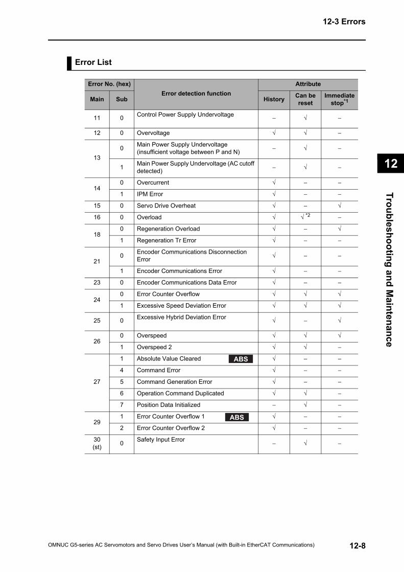
12-3 Errors
12
Troubleshooting and Maintenance
Error List
Error No. (hex)Error detection function
Attribute
Main Sub History Can be reset
Immediate stop*1
11 0 Control Power Supply Undervoltage − √ −
12 0 Overvoltage √ √ −
130 Main Power Supply Undervoltage
(insufficient voltage between P and N) − √ −
1 Main Power Supply Undervoltage (AC cutoff detected) − √ −
140 Overcurrent √ − −
1 IPM Error √ − −
15 0 Servo Drive Overheat √ − √
16 0 Overload √ √ *2 −
180 Regeneration Overload √ − √
1 Regeneration Tr Error √ − −
210 Encoder Communications Disconnection
Error √ − −
1 Encoder Communications Error √ − −
23 0 Encoder Communications Data Error √ − −
240 Error Counter Overflow √ √ √
1 Excessive Speed Deviation Error √ √ √
25 0 Excessive Hybrid Deviation Error √ − √
260 Overspeed √ √ √
1 Overspeed 2 √ √ −
27
1 Absolute Value Cleared √ − −
4 Command Error √ − −
5 Command Generation Error √ − −
6 Operation Command Duplicated √ √ −
7 Position Data Initialized − √ −
291 Error Counter Overflow 1 √ − −
2 Error Counter Overflow 2 √ − −
30(st) 0 Safety Input Error − √ −
ABS
ABS
12-8OMNUC G5-series AC Servomotors and Servo Drives User’s Manual (with Built-in EtherCAT Communications)
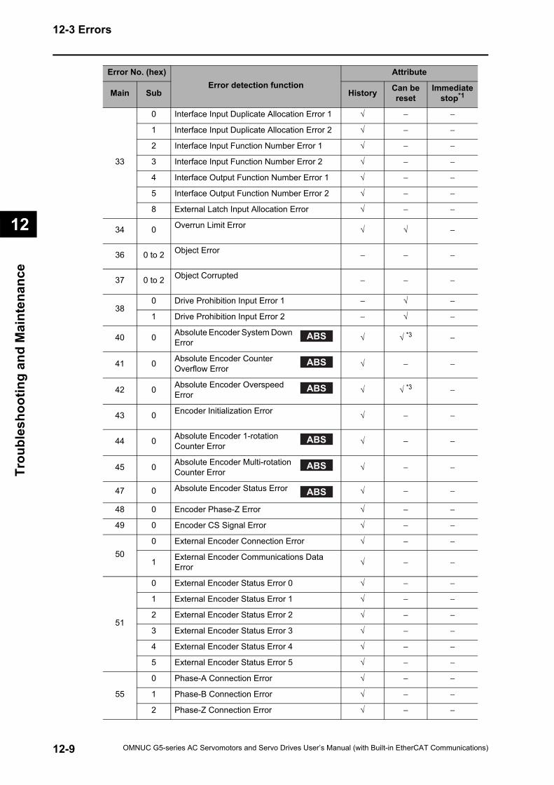
12-3 Errors
12
Trou
bles
hoot
ing
and
Mai
nten
ance
33
0 Interface Input Duplicate Allocation Error 1 √ − −
1 Interface Input Duplicate Allocation Error 2 √ − −
2 Interface Input Function Number Error 1 √ − −
3 Interface Input Function Number Error 2 √ − −
4 Interface Output Function Number Error 1 √ − −
5 Interface Output Function Number Error 2 √ − −
8 External Latch Input Allocation Error √ − −
34 0 Overrun Limit Error √ √ −
36 0 to 2 Object Error − − −
37 0 to 2 Object Corrupted − − −
380 Drive Prohibition Input Error 1 − √ −
1 Drive Prohibition Input Error 2 − √ −
40 0 Absolute Encoder System Down Error √ √ *3 −
41 0 Absolute Encoder Counter Overflow Error √ − −
42 0 Absolute Encoder Overspeed Error √ √ *3 −
43 0 Encoder Initialization Error √ − −
44 0 Absolute Encoder 1-rotation Counter Error √ − −
45 0 Absolute Encoder Multi-rotation Counter Error √ − −
47 0 Absolute Encoder Status Error √ − −
48 0 Encoder Phase-Z Error √ − −
49 0 Encoder CS Signal Error √ − −
500 External Encoder Connection Error √ − −
1 External Encoder Communications Data Error √ − −
51
0 External Encoder Status Error 0 √ − −
1 External Encoder Status Error 1 √ − −
2 External Encoder Status Error 2 √ − −
3 External Encoder Status Error 3 √ − −
4 External Encoder Status Error 4 √ − −
5 External Encoder Status Error 5 √ − −
55
0 Phase-A Connection Error √ − −
1 Phase-B Connection Error √ − −
2 Phase-Z Connection Error √ − −
Error No. (hex)Error detection function
Attribute
Main Sub History Can be reset
Immediate stop*1
ABS
ABS
ABS
ABS
ABS
ABS
12-9 OMNUC G5-series AC Servomotors and Servo Drives User’s Manual (with Built-in EtherCAT Communications)
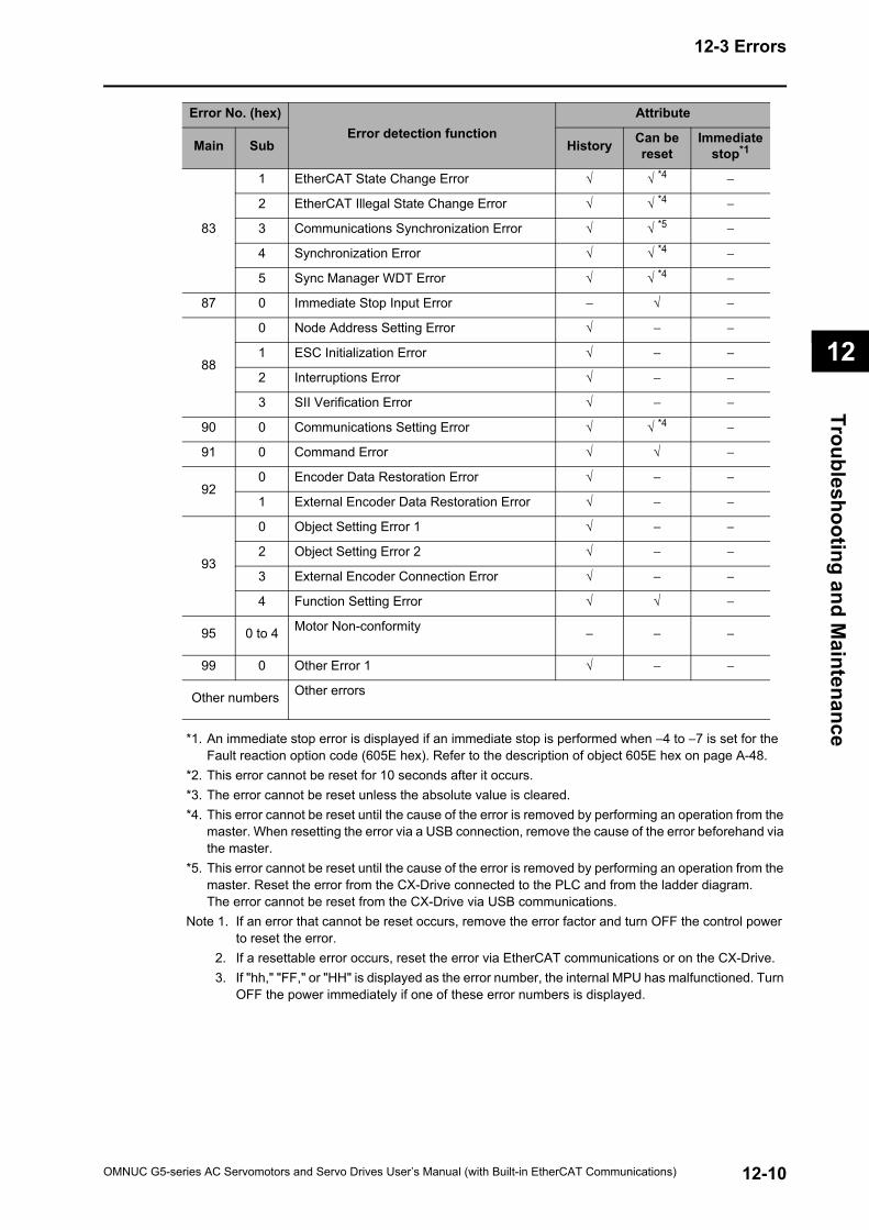
12-3 Errors
12
Troubleshooting and Maintenance
*1. An immediate stop error is displayed if an immediate stop is performed when −4 to −7 is set for theFault reaction option code (605E hex). Refer to the description of object 605E hex on page A-48.*2. This error cannot be reset for 10 seconds after it occurs.*3. The error cannot be reset unless the absolute value is cleared.*4. This error cannot be reset until the cause of the error is removed by performing an operation from the
master. When resetting the error via a USB connection, remove the cause of the error beforehand via the master.
*5. This error cannot be reset until the cause of the error is removed by performing an operation from the master. Reset the error from the CX-Drive connected to the PLC and from the ladder diagram.The error cannot be reset from the CX-Drive via USB communications.
Note 1. If an error that cannot be reset occurs, remove the error factor and turn OFF the control power to reset the error.
2. If a resettable error occurs, reset the error via EtherCAT communications or on the CX-Drive.3. If "hh," "FF," or "HH" is displayed as the error number, the internal MPU has malfunctioned. Turn
OFF the power immediately if one of these error numbers is displayed.
83
1 EtherCAT State Change Error √ √ *4 −
2 EtherCAT Illegal State Change Error √ √ *4 −
3 Communications Synchronization Error √ √ *5 −
4 Synchronization Error √ √ *4 −
5 Sync Manager WDT Error √ √ *4 −
87 0 Immediate Stop Input Error − √ −
88
0 Node Address Setting Error √ − −
1 ESC Initialization Error √ − −
2 Interruptions Error √ − −
3 SII Verification Error √ − −
90 0 Communications Setting Error √ √ *4 −
91 0 Command Error √ √ −
920 Encoder Data Restoration Error √ − −
1 External Encoder Data Restoration Error √ − −
93
0 Object Setting Error 1 √ − −
2 Object Setting Error 2 √ − −
3 External Encoder Connection Error √ − −
4 Function Setting Error √ √ −
95 0 to 4 Motor Non-conformity − − −
99 0 Other Error 1 √ − −
Other numbers Other errors
Error No. (hex)Error detection function
Attribute
Main Sub History Can be reset
Immediate stop*1
12-10OMNUC G5-series AC Servomotors and Servo Drives User’s Manual (with Built-in EtherCAT Communications)
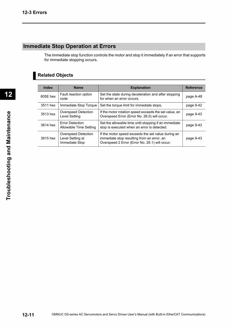
12-3 Errors
12
Trou
bles
hoot
ing
and
Mai
nten
ance
Immediate Stop Operation at Errors The immediate stop function controls the motor and stop it immediately if an error that supportsfor immediate stopping occurs.
Related Objects
Index Name Explanation Reference
605E hex Fault reaction option code
Set the state during deceleration and after stopping for when an error occurs. page A-48
3511 hex Immediate Stop Torque Set the torque limit for immediate stops. page 9-42
3513 hex Overspeed Detection Level Setting
If the motor rotation speed exceeds the set value, an Overspeed Error (Error No. 26.0) will occur. page 9-43
3614 hex Error Detection Allowable Time Setting
Set the allowable time until stopping if an immediate stop is executed when an error is detected. page 9-43
3615 hexOverspeed Detection Level Setting at Immediate Stop
If the motor speed exceeds the set value during an immediate stop resulting from an error, an Overspeed 2 Error (Error No. 26.1) will occur.
page 9-43
12-11 OMNUC G5-series AC Servomotors and Servo Drives User’s Manual (with Built-in EtherCAT Communications)
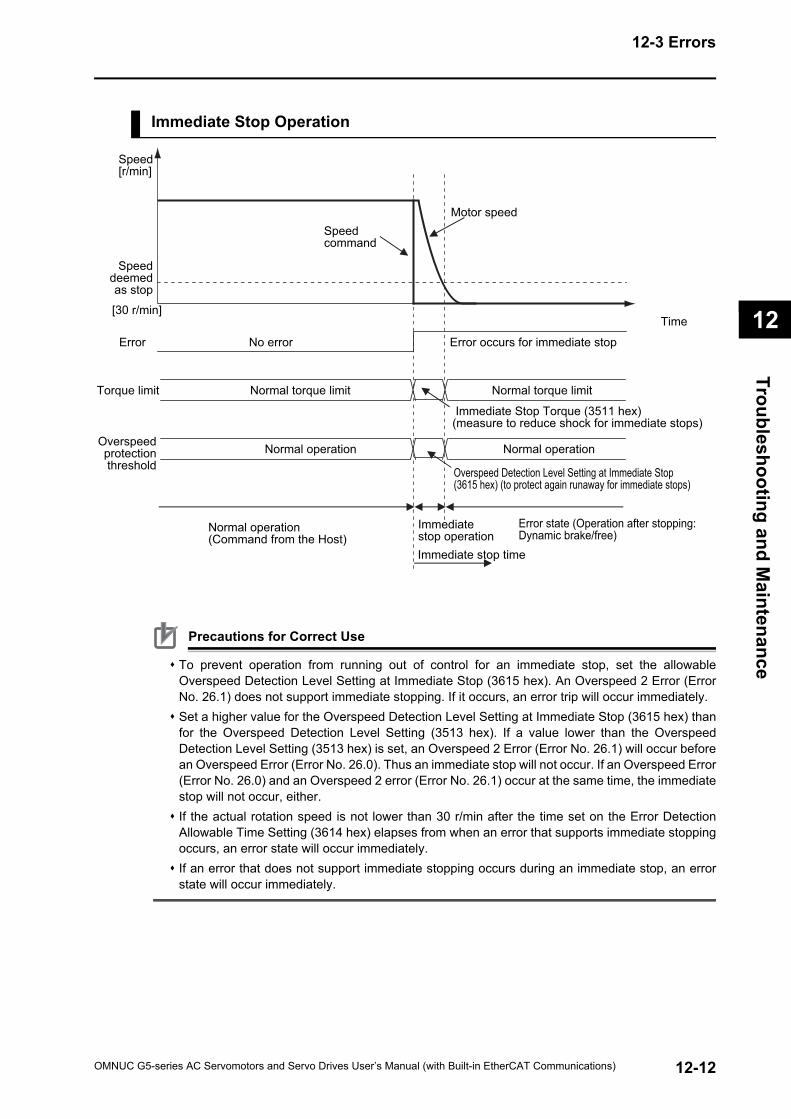
12-3 Errors
12
Troubleshooting and Maintenance
Immediate Stop Operation
Precautions for Correct Use
To prevent operation from running out of control for an immediate stop, set the allowableOverspeed Detection Level Setting at Immediate Stop (3615 hex). An Overspeed 2 Error (ErrorNo. 26.1) does not support immediate stopping. If it occurs, an error trip will occur immediately.Set a higher value for the Overspeed Detection Level Setting at Immediate Stop (3615 hex) thanfor the Overspeed Detection Level Setting (3513 hex). If a value lower than the OverspeedDetection Level Setting (3513 hex) is set, an Overspeed 2 Error (Error No. 26.1) will occur beforean Overspeed Error (Error No. 26.0). Thus an immediate stop will not occur. If an Overspeed Error(Error No. 26.0) and an Overspeed 2 error (Error No. 26.1) occur at the same time, the immediatestop will not occur, either.If the actual rotation speed is not lower than 30 r/min after the time set on the Error DetectionAllowable Time Setting (3614 hex) elapses from when an error that supports immediate stoppingoccurs, an error state will occur immediately.If an error that does not support immediate stopping occurs during an immediate stop, an errorstate will occur immediately.
Torque limit
Speed [r/min]
Time
Error state (Operation after stopping: Dynamic brake/free)
Immediatestop operation
Normal operation (Command from the Host)
Speed command
Motor speed
Normal torque limitNormal torque limit
Error occurs for immediate stopNo errorError
Speeddeemedas stop
[30 r/min]
Immediate stop time
Overspeedprotectionthreshold
Normal operationNormal operation
Overspeed Detection Level Setting at Immediate Stop (3615 hex) (to protect again runaway for immediate stops)
Immediate Stop Torque (3511 hex) (measure to reduce shock for immediate stops)
12-12OMNUC G5-series AC Servomotors and Servo Drives User’s Manual (with Built-in EtherCAT Communications)
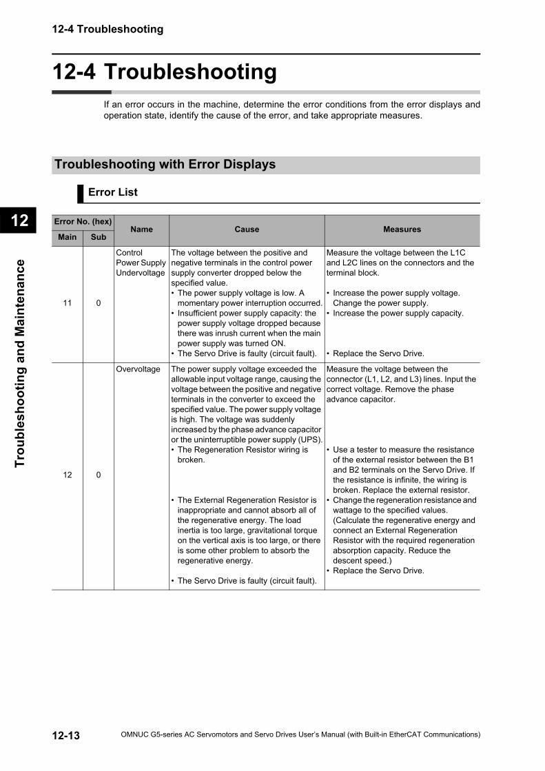
12-4 Troubleshooting
12
Trou
bles
hoot
ing
and
Mai
nten
ance
12-4 TroubleshootingIf an error occurs in the machine, determine the error conditions from the error displays andoperation state, identify the cause of the error, and take appropriate measures.
Troubleshooting with Error Displays
Error List
Error No. (hex)Name Cause Measures
Main Sub
11 0
Control Power Supply Undervoltage
The voltage between the positive and negative terminals in the control power supply converter dropped below the specified value.• The power supply voltage is low. A
momentary power interruption occurred.• Insufficient power supply capacity: the
power supply voltage dropped because there was inrush current when the main power supply was turned ON.
• The Servo Drive is faulty (circuit fault).
Measure the voltage between the L1C and L2C lines on the connectors and the terminal block.
• Increase the power supply voltage. Change the power supply.
• Increase the power supply capacity.
• Replace the Servo Drive.
12 0
Overvoltage The power supply voltage exceeded the allowable input voltage range, causing the voltage between the positive and negative terminals in the converter to exceed the specified value. The power supply voltage is high. The voltage was suddenly increased by the phase advance capacitor or the uninterruptible power supply (UPS).• The Regeneration Resistor wiring is
broken.
• The External Regeneration Resistor is inappropriate and cannot absorb all of the regenerative energy. The load inertia is too large, gravitational torque on the vertical axis is too large, or there is some other problem to absorb the regenerative energy.
• The Servo Drive is faulty (circuit fault).
Measure the voltage between the connector (L1, L2, and L3) lines. Input the correct voltage. Remove the phase advance capacitor.
• Use a tester to measure the resistance of the external resistor between the B1 and B2 terminals on the Servo Drive. If the resistance is infinite, the wiring is broken. Replace the external resistor.
• Change the regeneration resistance and wattage to the specified values. (Calculate the regenerative energy and connect an External Regeneration Resistor with the required regeneration absorption capacity. Reduce the descent speed.)
• Replace the Servo Drive.
12-13 OMNUC G5-series AC Servomotors and Servo Drives User’s Manual (with Built-in EtherCAT Communications)
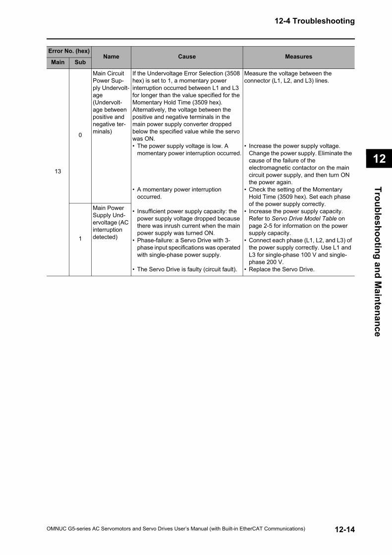
12-4 Troubleshooting
12
Troubleshooting and Maintenance
13
0
Main Circuit Power Sup-ply Undervolt-age (Undervolt-age between positive and negative ter-minals)
If the Undervoltage Error Selection (3508 hex) is set to 1, a momentary power interruption occurred between L1 and L3 for longer than the value specified for the Momentary Hold Time (3509 hex). Alternatively, the voltage between the positive and negative terminals in the main power supply converter dropped below the specified value while the servo was ON.• The power supply voltage is low. A
momentary power interruption occurred.
• A momentary power interruption occurred.
• Insufficient power supply capacity: the power supply voltage dropped because there was inrush current when the main power supply was turned ON.
• Phase-failure: a Servo Drive with 3-phase input specifications was operated with single-phase power supply.
• The Servo Drive is faulty (circuit fault).
Measure the voltage between the connector (L1, L2, and L3) lines.
• Increase the power supply voltage. Change the power supply. Eliminate the cause of the failure of the electromagnetic contactor on the main circuit power supply, and then turn ON the power again.
• Check the setting of the Momentary Hold Time (3509 hex). Set each phase of the power supply correctly.
• Increase the power supply capacity. Refer to Servo Drive Model Table on page 2-5 for information on the power supply capacity.
• Connect each phase (L1, L2, and L3) of the power supply correctly. Use L1 and L3 for single-phase 100 V and single-phase 200 V.
• Replace the Servo Drive.
1
Main Power Supply Und-ervoltage (AC interruption detected)
Error No. (hex)Name Cause Measures
Main Sub
12-14OMNUC G5-series AC Servomotors and Servo Drives User’s Manual (with Built-in EtherCAT Communications)
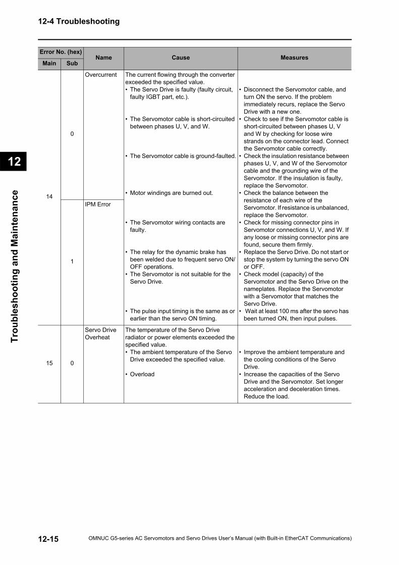
12-4 Troubleshooting
12
Trou
bles
hoot
ing
and
Mai
nten
ance
140
Overcurrent The current flowing through the converter exceeded the specified value.• The Servo Drive is faulty (faulty circuit,
faulty IGBT part, etc.).
• The Servomotor cable is short-circuited between phases U, V, and W.
• The Servomotor cable is ground-faulted.
• Motor windings are burned out.
• The Servomotor wiring contacts are faulty.
• The relay for the dynamic brake has been welded due to frequent servo ON/OFF operations.
• The Servomotor is not suitable for the Servo Drive.
• The pulse input timing is the same as or earlier than the servo ON timing.
• Disconnect the Servomotor cable, and turn ON the servo. If the problem immediately recurs, replace the Servo Drive with a new one.
• Check to see if the Servomotor cable is short-circuited between phases U, V and W by checking for loose wire strands on the connector lead. Connect the Servomotor cable correctly.
• Check the insulation resistance between phases U, V, and W of the Servomotor cable and the grounding wire of the Servomotor. If the insulation is faulty, replace the Servomotor.
• Check the balance between the resistance of each wire of the Servomotor. If resistance is unbalanced, replace the Servomotor.
• Check for missing connector pins in Servomotor connections U, V, and W. If any loose or missing connector pins are found, secure them firmly.
• Replace the Servo Drive. Do not start or stop the system by turning the servo ON or OFF.
• Check model (capacity) of the Servomotor and the Servo Drive on the nameplates. Replace the Servomotor with a Servomotor that matches the Servo Drive.
• Wait at least 100 ms after the servo has been turned ON, then input pulses.
1
IPM Error
15 0
Servo Drive Overheat
The temperature of the Servo Drive radiator or power elements exceeded the specified value.• The ambient temperature of the Servo
Drive exceeded the specified value.
• Overload
• Improve the ambient temperature and the cooling conditions of the Servo Drive.
• Increase the capacities of the Servo Drive and the Servomotor. Set longer acceleration and deceleration times. Reduce the load.
Error No. (hex)Name Cause Measures
Main Sub
12-15 OMNUC G5-series AC Servomotors and Servo Drives User’s Manual (with Built-in EtherCAT Communications)
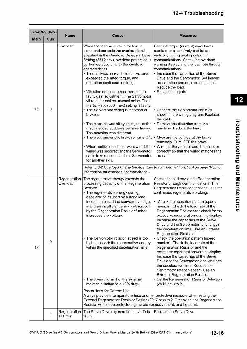
12-4 Troubleshooting
12
Troubleshooting and Maintenance
16 0
Overload When the feedback value for torque command exceeds the overload level specified in the Overload Detection Level Setting (3512 hex), overload protection is performed according to the overload characteristics. • The load was heavy, the effective torque
exceeded the rated torque, and operation continued too long.
• Vibration or hunting occurred due to faulty gain adjustment. The Servomotor vibrates or makes unusual noise. The Inertia Ratio (3004 hex) setting is faulty.
• The Servomotor wiring is incorrect or broken.
• The machine was hit by an object, or the machine load suddenly became heavy. The machine was distorted.
• The electromagnetic brake remains ON.
• When multiple machines were wired, the wiring was incorrect and the Servomotor cable to was connected to a Servomotor for another axis.
Check if torque (current) waveforms oscillate or excessively oscillates vertically during analog output or communications. Check the overload warning display and the load rate through communications.• Increase the capacities of the Servo
Drive and the Servomotor. Set longer acceleration and deceleration times. Reduce the load.
• Readjust the gain.
• Connect the Servomotor cable as shown in the wiring diagram. Replace the cable.
• Remove the distortion from the machine. Reduce the load.
• Measure the voltage at the brake terminals. Turn OFF the brake.
• Wire the Servomotor and the encoder correctly so that the wiring matches the axes.
Refer to 3-2 Overload Characteristics (Electronic Thermal Function) on page 3-36 for information on overload characteristics.
180
Regeneration Overload
The regenerative energy exceeds the processing capacity of the Regeneration Resistor.• The regenerative energy during
deceleration caused by a large load inertia increased the converter voltage, and then insufficient energy absorption by the Regeneration Resistor further increased the voltage.
• The Servomotor rotation speed is too high to absorb the regenerative energy within the specified deceleration time.
• The operating limit of the external resistor is limited to a 10% duty.
Check the load rate of the Regeneration Resistor through communications. This Regeneration Resistor cannot be used for continuous regenerative braking.
• Check the operation pattern (speed monitor). Check the load rate of the Regeneration Resistor and check for the excessive regeneration warning display. Increase the capacities of the Servo Drive and the Servomotor, and length the deceleration time. Use an External Regeneration Resistor.
• Check the operation pattern (speed monitor). Check the load rate of the Regeneration Resistor and the excessive regeneration warning display. Increase the capacities of the Servo Drive and the Servomotor, and lengthen the deceleration time. Reduce the Servomotor rotation speed. Use an External Regeneration Resistor.
• Set the Regeneration Resistor Selection (3016 hex) to 2.
Precautions for Correct UseAlways provide a temperature fuse or other protective measure when setting the External Regeneration Resistor Setting (3017 hex) to 2. Otherwise, the Regeneration Resistor will not be protected, generate excessive heat, and be burnt.
1 Regeneration Tr Error
The Servo Drive regeneration drive Tr is faulty.
Replace the Servo Drive.
Error No. (hex)Name Cause Measures
Main Sub
12-16OMNUC G5-series AC Servomotors and Servo Drives User’s Manual (with Built-in EtherCAT Communications)
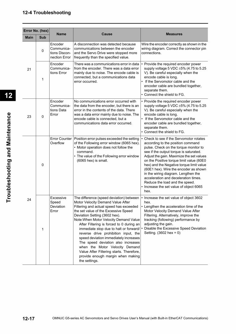
12-4 Troubleshooting
12
Trou
bles
hoot
ing
and
Mai
nten
ance
21
0
Encoder Communica-tions Discon-nection Error
A disconnection was detected because communications between the encoder and the Servo Drive were stopped more frequently than the specified value.
Wire the encoder correctly as shown in the wiring diagram. Correct the connector pin connections.
1
Encoder Communica-tions Error
There was a communications error in data from the encoder. There was a data error mainly due to noise. The encode cable is connected, but a communications data error occurred.
• Provide the required encoder power supply voltage 5 VDC ±5% (4.75 to 5.25 V). Be careful especially when the encode cable is long.
• If the Servomotor cable and the encoder cable are bundled together, separate them.
• Connect the shield to FG.
23 0
Encoder Communica-tions Data Error
No communications error occurred with the data from the encoder, but there is an error in the contents of the data. There was a data error mainly due to noise. The encode cable is connected, but a communications data error occurred.
• Provide the required encoder power supply voltage 5 VDC ±5% (4.75 to 5.25 V). Be careful especially when the encode cable is long.
• If the Servomotor cable and the encoder cable are bundled together, separate them.
• Connect the shield to FG.
24
0
Error Counter Overflow
Position error pulses exceeded the setting of the Following error window (6065 hex).• Motor operation does not follow the
command.• The value of the Following error window
(6065 hex) is small.
• Check to see if the Servomotor rotates according to the position command pulse. Check on the torque monitor to see if the output torque is saturated. Adjust the gain. Maximize the set values on the Positive torque limit value (60E0 hex) and the Negative torque limit value (60E1 hex). Wire the encoder as shown in the wiring diagram. Lengthen the acceleration and deceleration times. Reduce the load and the speed.
• Increase the set value of object 6065 hex.
1
Excessive Speed Deviation Error
The difference (speed deviation) between Motor Velocity Demand Value After Filtering and actual speed has exceeded the set value of the Excessive Speed Deviation Setting (3602 hex).Note:When Motor Velocity Demand Value
After Filtering is forced to 0 during animmediate stop due to halt or forward/reverse drive prohibition input, thespeed deviation immediately increasesThe speed deviation also increaseswhen the Motor Velocity DemandValue After Filtering starts. Therefore,provide enough margin when makingthe settings.
• Increase the set value of object 3602 hex.
• Lengthen the acceleration time of the Motor Velocity Demand Value After Filtering. Alternatively, improve the tracking (following) performance by adjusting the gain.
• Disable the Excessive Speed Deviation Setting. (3602 hex = 0)
Error No. (hex)Name Cause Measures
Main Sub
12-17 OMNUC G5-series AC Servomotors and Servo Drives User’s Manual (with Built-in EtherCAT Communications)
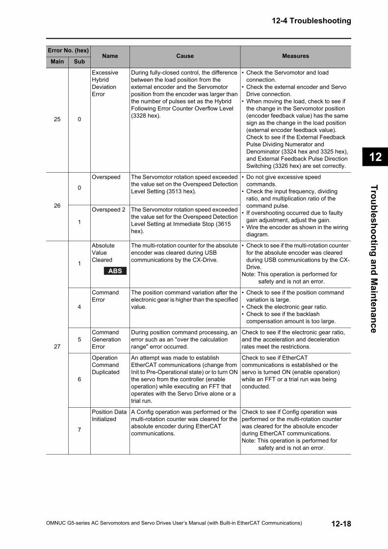
12-4 Troubleshooting
12
Troubleshooting and Maintenance
25 0
Excessive Hybrid Deviation Error
During fully-closed control, the difference between the load position from the external encoder and the Servomotor position from the encoder was larger than the number of pulses set as the Hybrid Following Error Counter Overflow Level (3328 hex).
• Check the Servomotor and load connection.
• Check the external encoder and Servo Drive connection.
• When moving the load, check to see if the change in the Servomotor position (encoder feedback value) has the same sign as the change in the load position (external encoder feedback value). Check to see if the External Feedback Pulse Dividing Numerator and Denominator (3324 hex and 3325 hex), and External Feedback Pulse Direction Switching (3326 hex) are set correctly.
26
0
Overspeed The Servomotor rotation speed exceeded the value set on the Overspeed Detection Level Setting (3513 hex).
• Do not give excessive speed commands.
• Check the input frequency, dividing ratio, and multiplication ratio of the command pulse.
• If overshooting occurred due to faulty gain adjustment, adjust the gain.
• Wire the encoder as shown in the wiring diagram.
1
Overspeed 2 The Servomotor rotation speed exceeded the value set for the Overspeed Detection Level Setting at Immediate Stop (3615 hex).
27
1
Absolute Value Cleared
The multi-rotation counter for the absolute encoder was cleared during USB communications by the CX-Drive.
• Check to see if the multi-rotation counter for the absolute encoder was cleared during USB communications by the CX-Drive.
Note: This operation is performed for safety and is not an error.
4
Command Error
The position command variation after the electronic gear is higher than the specified value.
• Check to see if the position command variation is large.
• Check the electronic gear ratio.• Check to see if the backlash
compensation amount is too large.
5Command Generation Error
During position command processing, an error such as an "over the calculation range" error occurred.
Check to see if the electronic gear ratio, and the acceleration and deceleration rates meet the restrictions.
6
Operation Command Duplicated
An attempt was made to establish EtherCAT communications (change from Init to Pre-Operational state) or to turn ON the servo from the controller (enable operation) while executing an FFT that operates with the Servo Drive alone or a trial run.
Check to see if EtherCAT communications is established or the servo is turned ON (enable operation) while an FFT or a trial run was being conducted.
7
Position Data Initialized
A Config operation was performed or the multi-rotation counter was cleared for the absolute encoder during EtherCAT communications.
Check to see if Config operation was performed or the multi-rotation counter was cleared for the absolute encoder during EtherCAT communications.Note: This operation is performed for
safety and is not an error.
Error No. (hex)Name Cause Measures
Main Sub
ABS
12-18OMNUC G5-series AC Servomotors and Servo Drives User’s Manual (with Built-in EtherCAT Communications)
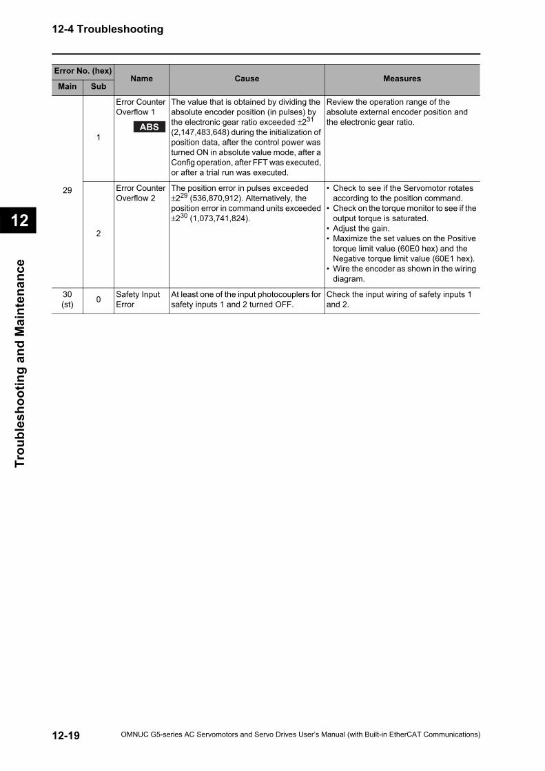
12-4 Troubleshooting
12
Trou
bles
hoot
ing
and
Mai
nten
ance
29
1
Error Counter Overflow 1
The value that is obtained by dividing the absolute encoder position (in pulses) by the electronic gear ratio exceeded ±231 (2,147,483,648) during the initialization of position data, after the control power was turned ON in absolute value mode, after a Config operation, after FFT was executed, or after a trial run was executed.
Review the operation range of the absolute external encoder position and the electronic gear ratio.
2
Error Counter Overflow 2
The position error in pulses exceeded ±229 (536,870,912). Alternatively, the position error in command units exceeded ±230 (1,073,741,824).
• Check to see if the Servomotor rotates according to the position command.
• Check on the torque monitor to see if the output torque is saturated.
• Adjust the gain.• Maximize the set values on the Positive
torque limit value (60E0 hex) and the Negative torque limit value (60E1 hex).
• Wire the encoder as shown in the wiring diagram.
30(st) 0 Safety Input
ErrorAt least one of the input photocouplers for safety inputs 1 and 2 turned OFF.
Check the input wiring of safety inputs 1 and 2.
Error No. (hex)Name Cause Measures
Main Sub
ABS
12-19 OMNUC G5-series AC Servomotors and Servo Drives User’s Manual (with Built-in EtherCAT Communications)
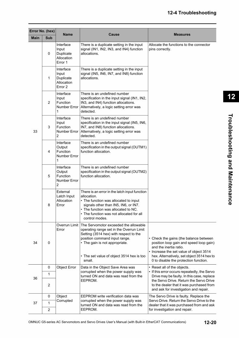
12-4 Troubleshooting
12
Troubleshooting and Maintenance
33
0
Interface Input Duplicate Allocation Error 1
There is a duplicate setting in the input signal (IN1, IN2, IN3, and IN4) function allocations.
Allocate the functions to the connector pins correctly.
1
Interface Input Duplicate Allocation Error 2
There is a duplicate setting in the input signal (IN5, IN6, IN7, and IN8) function allocations.
2
Interface Input Function Number Error 1
There is an undefined number specification in the input signal (IN1, IN2, IN3, and IN4) function allocations. Alternatively, a logic setting error was detected.
3
Interface Input Function Number Error 2
There is an undefined number specification in the input signal (IN5, IN6, IN7, and IN8) function allocations. Alternatively, a logic setting error was detected.
4
Interface Output Function Number Error 1
There is an undefined number specification in the output signal (OUTM1) function allocation.
5
Interface Output Function Number Error 2
There is an undefined number specification in the output signal (OUTM2) function allocation.
8
External Latch Input Allocation Error
There is an error in the latch input function allocation.• The function was allocated to input
signals other than IN5, IN6, or IN7.• The function was allocated to NC.• The function was not allocated for all
control modes.
34 0
Overrun Limit Error
The Servomotor exceeded the allowable operating range set in the Overrun Limit Setting (3514 hex) with respect to the position command input range.• The gain is not appropriate.
• The set value of object 3514 hex is too small.
• Check the gains (the balance between position loop gain and speed loop gain) and the inertia ratio.
• Increase the set value of object 3514 hex. Alternatively, set object 3514 hex to 0 to disable the protection function.
36
0 Object Error Data in the Object Save Area was corrupted when the power supply was turned ON and data was read from the EEPROM.
• Reset all of the objects.• If this error occurs repeatedly, the Servo
Drive may be faulty. In this case, replace the Servo Drive. Return the Servo Drive to the dealer that it was purchased from and ask for investigation and repair.
1
2
37
0 Object Corrupted
EEPROM write verification data was corrupted when the power supply was turned ON and data was read from the EEPROM.
The Servo Drive is faulty. Replace the Servo Drive. Return the Servo Drive to the dealer that it was purchased from and ask for investigation and repair.
1
2
Error No. (hex)Name Cause Measures
Main Sub
12-20OMNUC G5-series AC Servomotors and Servo Drives User’s Manual (with Built-in EtherCAT Communications)
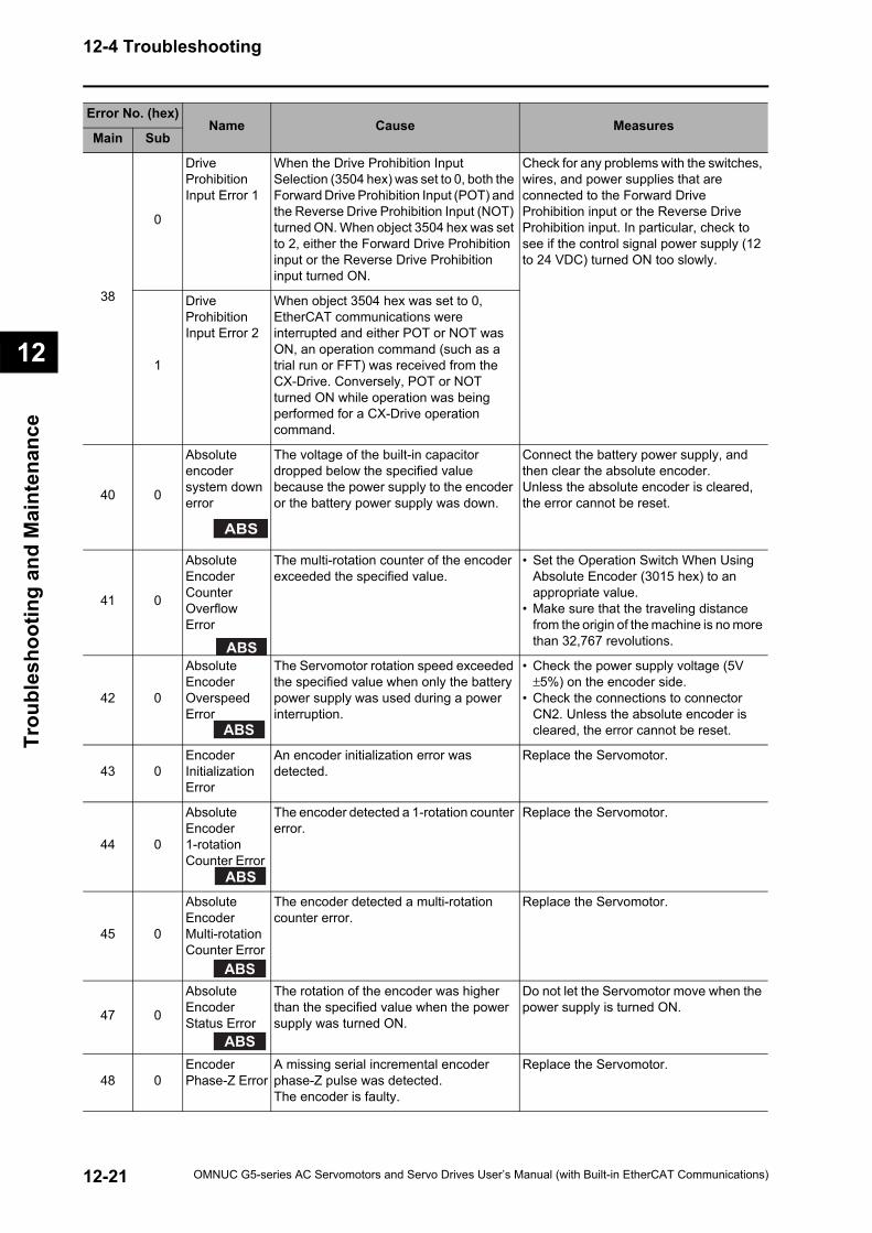
12-4 Troubleshooting
12
Trou
bles
hoot
ing
and
Mai
nten
ance
38
0
Drive Prohibition Input Error 1
When the Drive Prohibition Input Selection (3504 hex) was set to 0, both the Forward Drive Prohibition Input (POT) and the Reverse Drive Prohibition Input (NOT) turned ON. When object 3504 hex was set to 2, either the Forward Drive Prohibition input or the Reverse Drive Prohibition input turned ON.
Check for any problems with the switches, wires, and power supplies that are connected to the Forward Drive Prohibition input or the Reverse Drive Prohibition input. In particular, check to see if the control signal power supply (12 to 24 VDC) turned ON too slowly.
1
Drive Prohibition Input Error 2
When object 3504 hex was set to 0, EtherCAT communications were interrupted and either POT or NOT was ON, an operation command (such as a trial run or FFT) was received from the CX-Drive. Conversely, POT or NOT turned ON while operation was being performed for a CX-Drive operation command.
40 0
Absolute encoder system down error
The voltage of the built-in capacitor dropped below the specified value because the power supply to the encoder or the battery power supply was down.
Connect the battery power supply, and then clear the absolute encoder.Unless the absolute encoder is cleared, the error cannot be reset.
41 0
Absolute Encoder Counter Overflow Error
The multi-rotation counter of the encoder exceeded the specified value.
• Set the Operation Switch When Using Absolute Encoder (3015 hex) to an appropriate value.
• Make sure that the traveling distance from the origin of the machine is no more than 32,767 revolutions.
42 0
Absolute Encoder Overspeed Error
The Servomotor rotation speed exceeded the specified value when only the battery power supply was used during a power interruption.
• Check the power supply voltage (5V ±5%) on the encoder side.
• Check the connections to connector CN2. Unless the absolute encoder is cleared, the error cannot be reset.
43 0Encoder Initialization Error
An encoder initialization error was detected.
Replace the Servomotor.
44 0
Absolute Encoder 1-rotation Counter Error
The encoder detected a 1-rotation counter error.
Replace the Servomotor.
45 0
Absolute Encoder Multi-rotation Counter Error
The encoder detected a multi-rotation counter error.
Replace the Servomotor.
47 0
Absolute Encoder Status Error
The rotation of the encoder was higher than the specified value when the power supply was turned ON.
Do not let the Servomotor move when the power supply is turned ON.
48 0Encoder Phase-Z Error
A missing serial incremental encoder phase-Z pulse was detected.The encoder is faulty.
Replace the Servomotor.
Error No. (hex)Name Cause Measures
Main Sub
ABS
ABS
ABS
ABS
ABS
ABS
12-21 OMNUC G5-series AC Servomotors and Servo Drives User’s Manual (with Built-in EtherCAT Communications)
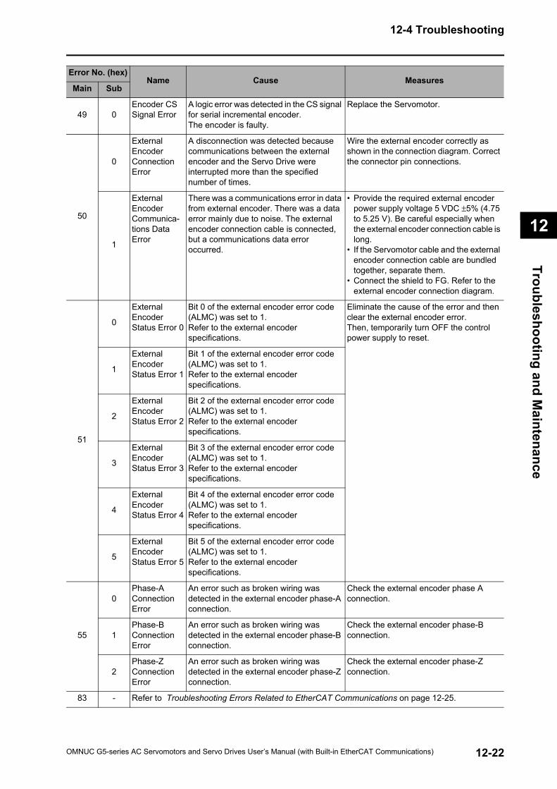
12-4 Troubleshooting
12
Troubleshooting and Maintenance
49 0Encoder CS Signal Error
A logic error was detected in the CS signal for serial incremental encoder.The encoder is faulty.
Replace the Servomotor.
50
0
External Encoder Connection Error
A disconnection was detected because communications between the external encoder and the Servo Drive were interrupted more than the specified number of times.
Wire the external encoder correctly as shown in the connection diagram. Correct the connector pin connections.
1
External Encoder Communica-tions Data Error
There was a communications error in data from external encoder. There was a data error mainly due to noise. The external encoder connection cable is connected, but a communications data error occurred.
• Provide the required external encoder power supply voltage 5 VDC ±5% (4.75 to 5.25 V). Be careful especially when the external encoder connection cable is long.
• If the Servomotor cable and the external encoder connection cable are bundled together, separate them.
• Connect the shield to FG. Refer to the external encoder connection diagram.
51
0
External Encoder Status Error 0
Bit 0 of the external encoder error code (ALMC) was set to 1.Refer to the external encoder specifications.
Eliminate the cause of the error and then clear the external encoder error.Then, temporarily turn OFF the control power supply to reset.
1
External Encoder Status Error 1
Bit 1 of the external encoder error code (ALMC) was set to 1.Refer to the external encoder specifications.
2
External Encoder Status Error 2
Bit 2 of the external encoder error code (ALMC) was set to 1.Refer to the external encoder specifications.
3
External Encoder Status Error 3
Bit 3 of the external encoder error code (ALMC) was set to 1.Refer to the external encoder specifications.
4
External Encoder Status Error 4
Bit 4 of the external encoder error code (ALMC) was set to 1.Refer to the external encoder specifications.
5
External Encoder Status Error 5
Bit 5 of the external encoder error code (ALMC) was set to 1.Refer to the external encoder specifications.
55
0Phase-A Connection Error
An error such as broken wiring was detected in the external encoder phase-A connection.
Check the external encoder phase A connection.
1Phase-B Connection Error
An error such as broken wiring was detected in the external encoder phase-B connection.
Check the external encoder phase-B connection.
2Phase-Z Connection Error
An error such as broken wiring was detected in the external encoder phase-Z connection.
Check the external encoder phase-Z connection.
83 - Refer to Troubleshooting Errors Related to EtherCAT Communications on page 12-25.
Error No. (hex)Name Cause Measures
Main Sub
12-22OMNUC G5-series AC Servomotors and Servo Drives User’s Manual (with Built-in EtherCAT Communications)
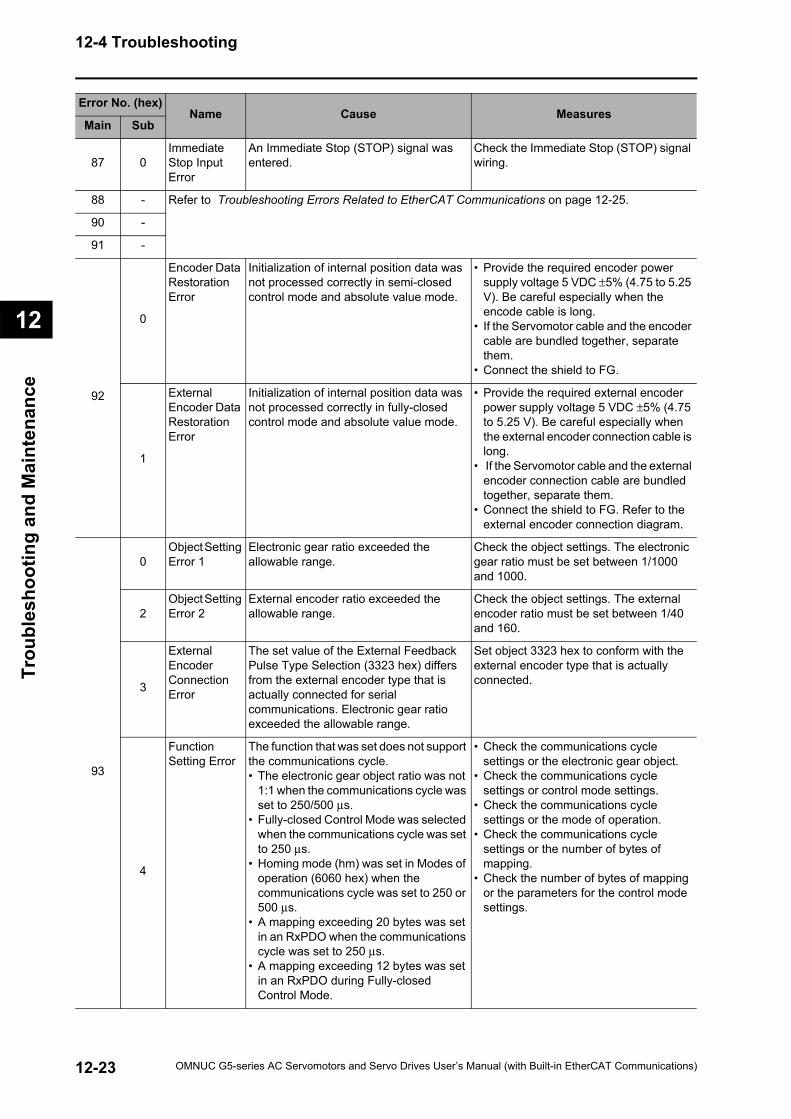
12-4 Troubleshooting
12
Trou
bles
hoot
ing
and
Mai
nten
ance
87 0Immediate Stop Input Error
An Immediate Stop (STOP) signal was entered.
Check the Immediate Stop (STOP) signal wiring.
88 - Refer to Troubleshooting Errors Related to EtherCAT Communications on page 12-25.
90 -
91 -
92
0
Encoder Data Restoration Error
Initialization of internal position data was not processed correctly in semi-closed control mode and absolute value mode.
• Provide the required encoder power supply voltage 5 VDC ±5% (4.75 to 5.25 V). Be careful especially when the encode cable is long.
• If the Servomotor cable and the encoder cable are bundled together, separate them.
• Connect the shield to FG.
1
External Encoder Data Restoration Error
Initialization of internal position data was not processed correctly in fully-closed control mode and absolute value mode.
• Provide the required external encoder power supply voltage 5 VDC ±5% (4.75 to 5.25 V). Be careful especially when the external encoder connection cable is long.
• If the Servomotor cable and the external encoder connection cable are bundled together, separate them.
• Connect the shield to FG. Refer to the external encoder connection diagram.
93
0Object Setting Error 1
Electronic gear ratio exceeded the allowable range.
Check the object settings. The electronic gear ratio must be set between 1/1000 and 1000.
2Object Setting Error 2
External encoder ratio exceeded the allowable range.
Check the object settings. The external encoder ratio must be set between 1/40 and 160.
3
External Encoder Connection Error
The set value of the External Feedback Pulse Type Selection (3323 hex) differs from the external encoder type that is actually connected for serial communications. Electronic gear ratio exceeded the allowable range.
Set object 3323 hex to conform with the external encoder type that is actually connected.
4
Function Setting Error
The function that was set does not support the communications cycle.• The electronic gear object ratio was not
1:1 when the communications cycle was set to 250/500 µs.
• Fully-closed Control Mode was selected when the communications cycle was set to 250 µs.
• Homing mode (hm) was set in Modes of operation (6060 hex) when the communications cycle was set to 250 or 500 µs.
• A mapping exceeding 20 bytes was set in an RxPDO when the communications cycle was set to 250 µs.
• A mapping exceeding 12 bytes was set in an RxPDO during Fully-closed Control Mode.
• Check the communications cycle settings or the electronic gear object.
• Check the communications cycle settings or control mode settings.
• Check the communications cycle settings or the mode of operation.
• Check the communications cycle settings or the number of bytes of mapping.
• Check the number of bytes of mapping or the parameters for the control mode settings.
Error No. (hex)Name Cause Measures
Main Sub
12-23 OMNUC G5-series AC Servomotors and Servo Drives User’s Manual (with Built-in EtherCAT Communications)
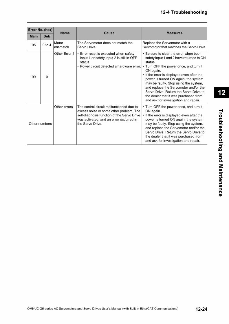
12-4 Troubleshooting
12
Troubleshooting and Maintenance
95 0 to 4 Motor mismatch
The Servomotor does not match the Servo Drive.
Replace the Servomotor with a Servomotor that matches the Servo Drive.
99 0
Other Error 1 • Error reset is executed when safety input 1 or safety input 2 is still in OFF status.
• Power circuit detected a hardware error.
• Be sure to clear the error when both safety input 1 and 2 have returned to ON status.
• Turn OFF the power once, and turn it ON again.
• If the error is displayed even after the power is turned ON again, the system may be faulty. Stop using the system, and replace the Servomotor and/or the Servo Drive. Return the Servo Drive to the dealer that it was purchased from and ask for investigation and repair.
Other numbers
Other errors The control circuit malfunctioned due to excess noise or some other problem. The self-diagnosis function of the Servo Drive was activated, and an error occurred in the Servo Drive.
• Turn OFF the power once, and turn it ON again.
• If the error is displayed even after the power is turned ON again, the system may be faulty. Stop using the system, and replace the Servomotor and/or the Servo Drive. Return the Servo Drive to the dealer that it was purchased from and ask for investigation and repair.
Error No. (hex)Name Cause Measures
Main Sub
12-24OMNUC G5-series AC Servomotors and Servo Drives User’s Manual (with Built-in EtherCAT Communications)
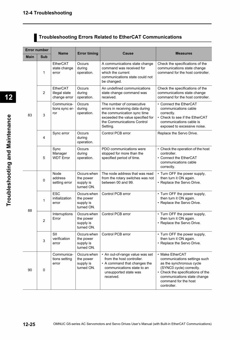
12-4 Troubleshooting
12
Trou
bles
hoot
ing
and
Mai
nten
ance
Troubleshooting Errors Related to EtherCAT Communications
Error numberName Error timing Cause Measures
Main Sub
83
1
EtherCAT state change error
Occurs during operation.
A communications state change command was received for which the current communications state could not be changed.
Check the specifications of the communications state change command for the host controller.
2EtherCAT illegal state change error
Occurs during operation.
An undefined communications state change command was received.
Check the specifications of the communications state change command for the host controller.
3
Communica-tions sync er-ror
Occurs during operation.
The number of consecutive errors in receiving data during the communication sync time exceeded the value specified for the Communications Control Setting.
• Connect the EtherCAT communications cable correctly.
• Check to see if the EtherCAT communications cable is exposed to excessive noise.
4Sync error Occurs
during operation.
Control PCB error Replace the Servo Drive.
5
Sync Manager WDT Error
Occurs during operation.
PDO communications were stopped for more than the specified period of time.
• Check the operation of the host controller.
• Connect the EtherCAT communications cable correctly.
88
0
Node address setting error
Occurs when the power supply is turned ON.
The node address that was read from the rotary switches was notbetween 00 and 99.
• Turn OFF the power supply, then turn it ON again.
• Replace the Servo Drive.
1
ESC initialization error
Occurs when the power supply is turned ON.
Control PCB error • Turn OFF the power supply, then turn it ON again.
• Replace the Servo Drive.
2
Interruptions Error
Occurs when the power supply is turned ON.
Control PCB error • Turn OFF the power supply, then turn it ON again.
• Replace the Servo Drive.
3
SII verification error
Occurs when the power supply is turned ON.
Control PCB error • Turn OFF the power supply, then turn it ON again.
• Replace the Servo Drive.
90 0
Communica-tions setting error
Occurs when the power supply is turned ON.
• An out-of-range value was set from the host controller.
• A command that changes the communications state to an unsupported state was received.
• Make EtherCAT communications settings such as the synchronous cycle (SYNC0 cycle) correctly.
• Check the specifications of the communications state change command for the host controller.
12-25 OMNUC G5-series AC Servomotors and Servo Drives User’s Manual (with Built-in EtherCAT Communications)
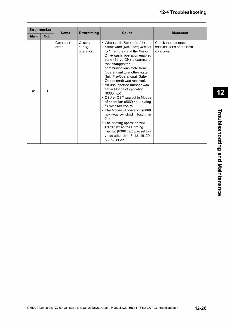
12-4 Troubleshooting
12
Troubleshooting and Maintenance
91 1
Command error
Occurs during operation.
• When bit 9 (Remote) of the Statusword (6041 hex) was set to 1 (remote), and the Servo Drive was in operation enabled state (Servo ON), a command that changes the communications state from Operational to another state (Init, Pre-Operational, Safe-Operational) was received.
• An unsupported number was set in Modes of operation (6060 hex).
• CSV or CST was set in Modes of operation (6060 hex) during fully-closed control.
• The Modes of operation (6060 hex) was switched in less than 2 ms.
• The homing operation was started when the Homing method (6098 hex) was set to a value other than 8, 12, 19, 20, 33, 34, or 35.
Check the command specifications of the host controller.
Error numberName Error timing Cause Measures
Main Sub
12-26OMNUC G5-series AC Servomotors and Servo Drives User’s Manual (with Built-in EtherCAT Communications)
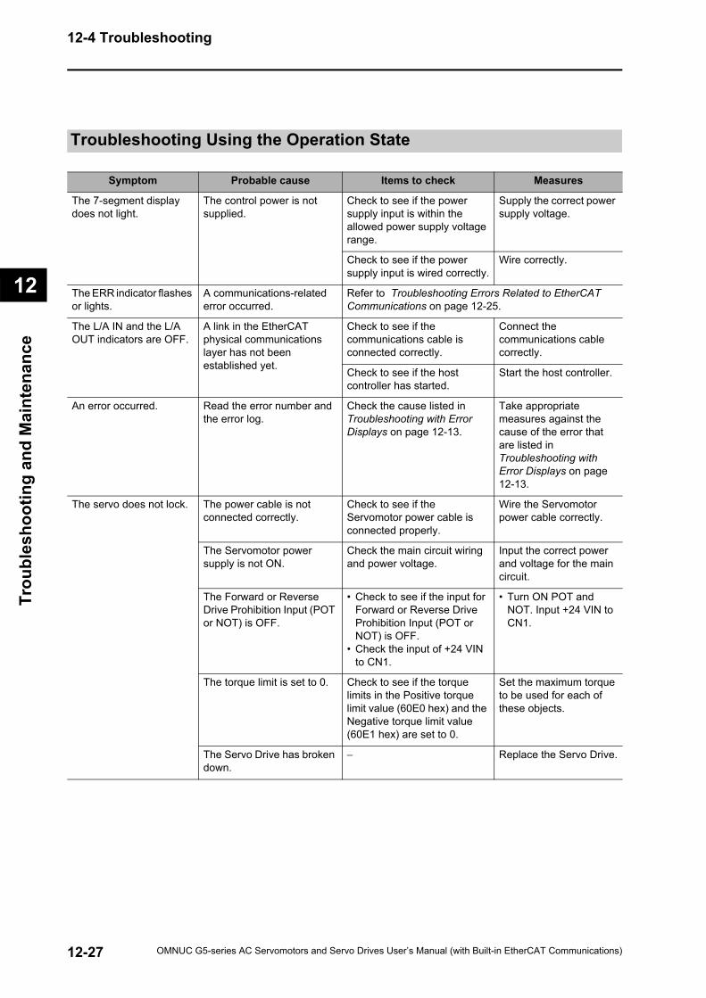
12-4 Troubleshooting
12
Trou
bles
hoot
ing
and
Mai
nten
ance
Troubleshooting Using the Operation State
Symptom Probable cause Items to check Measures
The 7-segment display does not light.
The control power is not supplied.
Check to see if the power supply input is within the allowed power supply voltage range.
Supply the correct power supply voltage.
Check to see if the power supply input is wired correctly.
Wire correctly.
The ERR indicator flashes or lights.
A communications-related error occurred.
Refer to Troubleshooting Errors Related to EtherCAT Communications on page 12-25.
The L/A IN and the L/A OUT indicators are OFF.
A link in the EtherCAT physical communications layer has not been established yet.
Check to see if the communications cable is connected correctly.
Connect the communications cable correctly.
Check to see if the host controller has started.
Start the host controller.
An error occurred. Read the error number and the error log.
Check the cause listed in Troubleshooting with Error Displays on page 12-13.
Take appropriate measures against the cause of the error that are listed in Troubleshooting with Error Displays on page 12-13.
The servo does not lock. The power cable is not connected correctly.
Check to see if the Servomotor power cable is connected properly.
Wire the Servomotor power cable correctly.
The Servomotor power supply is not ON.
Check the main circuit wiring and power voltage.
Input the correct power and voltage for the main circuit.
The Forward or Reverse Drive Prohibition Input (POT or NOT) is OFF.
• Check to see if the input for Forward or Reverse Drive Prohibition Input (POT or NOT) is OFF.
• Check the input of +24 VIN to CN1.
• Turn ON POT and NOT. Input +24 VIN to CN1.
The torque limit is set to 0. Check to see if the torque limits in the Positive torque limit value (60E0 hex) and the Negative torque limit value (60E1 hex) are set to 0.
Set the maximum torque to be used for each of these objects.
The Servo Drive has broken down.
− Replace the Servo Drive.
12-27 OMNUC G5-series AC Servomotors and Servo Drives User’s Manual (with Built-in EtherCAT Communications)

12-4 Troubleshooting
12
Troubleshooting and Maintenance
The servo locks but the Servomotor does not rotate.
The host controller does not give a command.
For a position command, check to see if the speed and position are set to 0.
Enter position and speed data. Start the Servomotor.
It is hard to determine if the Servomotor is rotating
Check to see it the speed command given by the host controller is too small.
Check the speed command from the host controller.
The holding brake is operating.
Check the brake interlock output (BKIR) signal and the +24 VDC power supply.
Check to see if the holding brake on a Servomotor with brake is released when the servo is locked.
The torque limits set in the Positive torque limit value (60E0 hex) and the Negative torque limit value (60E1 hex) are too small.
Check to see if the torque limits in objects 60E0 hex and 60E1 hex are set to a value close to 0.
Set the maximum torque to be used for each of these objects.
The Servo Drive has broken down.
− Replace the Servo Drive.
The Forward or Reverse Drive Prohibition Input (POT or NOT) is OFF.
Check the ON/OFF state of the POT and NOT signals from the CX-Drive.
• Turn ON the POT and NOT signals.
• Disable them in the settings when the POT and NOT signals are not used.
The control mode does not conform to the command.
Check the set value of the Control Mode Selection (3001 hex).
Set the control mode according to the command.
The Servomotor power cable is wired incorrectly.
Check the wiring. Wire correctly.
The encoder cable is wired incorrectly.
Power is not supplied. Check the power supply and the 7-segment display.
Turn ON the power.
Check the voltage between the power terminals.
Wire the power-ON circuit correctly.
The Servo Drive has broken down.
− Replace the Servo Drive.
The Servomotor operates momentarily, but then it does not operate after that.
The position commands given are too little.
Check the position data and the electronic gear ratio at the host controller.
Set the correct data.
The Servomotor power cable is wired incorrectly.
Check the wiring of the Servomotor power cable's phases U, V, and W.
Wire correctly.
The encoder cable is wired incorrectly.
Check the encoder cable's wiring.
Wire correctly.
The Servomotor rotates without a command.
There are inputs of small values in speed control mode.
Check if there is an input in speed control mode.
Set the speed command to 0. Alternatively, change the mode to position control mode.
The Servo Drive has broken down.
− Replace the Servo Drive.
Symptom Probable cause Items to check Measures
12-28OMNUC G5-series AC Servomotors and Servo Drives User’s Manual (with Built-in EtherCAT Communications)
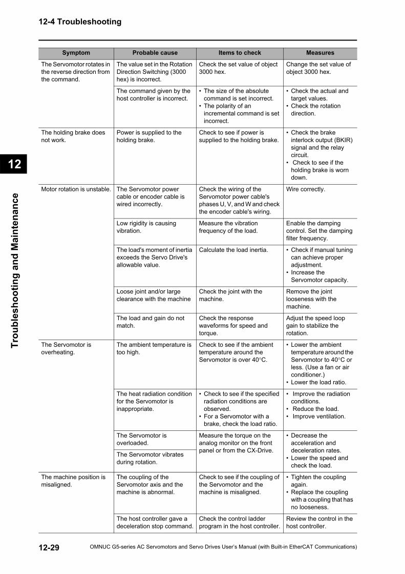
12-4 Troubleshooting
12
Trou
bles
hoot
ing
and
Mai
nten
ance
The Servomotor rotates in the reverse direction from the command.
The value set in the Rotation Direction Switching (3000 hex) is incorrect.
Check the set value of object 3000 hex.
Change the set value of object 3000 hex.
The command given by the host controller is incorrect.
• The size of the absolute command is set incorrect.
• The polarity of an incremental command is set incorrect.
• Check the actual and target values.
• Check the rotation direction.
The holding brake does not work.
Power is supplied to the holding brake.
Check to see if power is supplied to the holding brake.
• Check the brake interlock output (BKIR) signal and the relay circuit.
• Check to see if the holding brake is worn down.
Motor rotation is unstable. The Servomotor power cable or encoder cable is wired incorrectly.
Check the wiring of the Servomotor power cable's phases U, V, and W and check the encoder cable's wiring.
Wire correctly.
Low rigidity is causing vibration.
Measure the vibration frequency of the load.
Enable the damping control. Set the damping filter frequency.
The load's moment of inertia exceeds the Servo Drive's allowable value.
Calculate the load inertia. • Check if manual tuning can achieve proper adjustment.
• Increase the Servomotor capacity.
Loose joint and/or large clearance with the machine
Check the joint with the machine.
Remove the joint looseness with the machine.
The load and gain do not match.
Check the response waveforms for speed and torque.
Adjust the speed loop gain to stabilize the rotation.
The Servomotor is overheating.
The ambient temperature is too high.
Check to see if the ambient temperature around the Servomotor is over 40°C.
• Lower the ambient temperature around the Servomotor to 40°C or less. (Use a fan or air conditioner.)
• Lower the load ratio.
The heat radiation condition for the Servomotor is inappropriate.
• Check to see if the specified radiation conditions are observed.
• For a Servomotor with a brake, check the load ratio.
• Improve the radiation conditions.
• Reduce the load.• Improve ventilation.
The Servomotor is overloaded.
Measure the torque on the analog monitor on the front panel or from the CX-Drive.
• Decrease the acceleration and deceleration rates.
• Lower the speed and check the load.
The Servomotor vibrates during rotation.
The machine position is misaligned.
The coupling of the Servomotor axis and the machine is abnormal.
Check to see if the coupling of the Servomotor and the machine is misaligned.
• Tighten the coupling again.
• Replace the coupling with a coupling that has no looseness.
The host controller gave a deceleration stop command.
Check the control ladder program in the host controller.
Review the control in the host controller.
Symptom Probable cause Items to check Measures
12-29 OMNUC G5-series AC Servomotors and Servo Drives User’s Manual (with Built-in EtherCAT Communications)
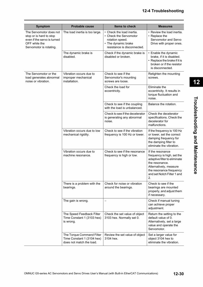
12-4 Troubleshooting
12
Troubleshooting and Maintenance
The Servomotor does not stop or is hard to stop even if the servo is turned OFF while the Servomotor is rotating.
The load inertia is too large. • Check the load inertia.• Check the Servomotor
rotation speed.• The dynamic brake
resistance is disconnected.
• Review the load inertia.• Replace the
Servomotor and Servo Drive with proper ones.
The dynamic brake is disabled.
Check if the dynamic brake is disabled or broken.
• Enable the dynamic brake, if it is disabled.
• Replace the brake if it is broken or if the resistor is disconnected.
The Servomotor or the load generates abnormal noise or vibration.
Vibration occurs due to improper mechanical installation.
Check to see if the Servomotor's mounting screws are loose.
Retighten the mounting screws.
Check the load for eccentricity.
Eliminate the eccentricity. It results in torque fluctuation and noise.
Check to see if the coupling with the load is unbalanced.
Balance the rotation.
Check to see if the decelerator is generating any abnormal noise.
Check the decelerator specifications. Check the decelerator for malfunctions.
Vibration occurs due to low mechanical rigidity.
Check to see if the vibration frequency is 100 Hz or lower.
If the frequency is 100 Hz or lower, set the correct damping frequency for the damping filter to eliminate the vibration.
Vibration occurs due to machine resonance.
Check to see if the resonance frequency is high or low.
If the resonance frequency is high, set the adaptive filter to eliminate the resonance. Alternatively, measure the resonance frequency and set Notch Filter 1 and 2.
There is a problem with the bearings.
Check for noise or vibration around the bearings.
Check to see if the bearings are mounted properly, and adjust them if necessary.
The gain is wrong. − Check if manual tuning can achieve proper adjustment.
The Speed Feedback Filter Time Constant 1 (3103 hex) is wrong.
Check the set value of object 3103 hex. Normally set 0.
Return the setting to the default value of 0. Alternatively, set a large value and operate the Servomotor.
The Torque Command Filter Time Constant 1 (3104 hex) does not match the load.
Review the set value of object 3104 hex.
Set a larger value for object 3104 hex to eliminate the vibration.
Symptom Probable cause Items to check Measures
12-30OMNUC G5-series AC Servomotors and Servo Drives User’s Manual (with Built-in EtherCAT Communications)
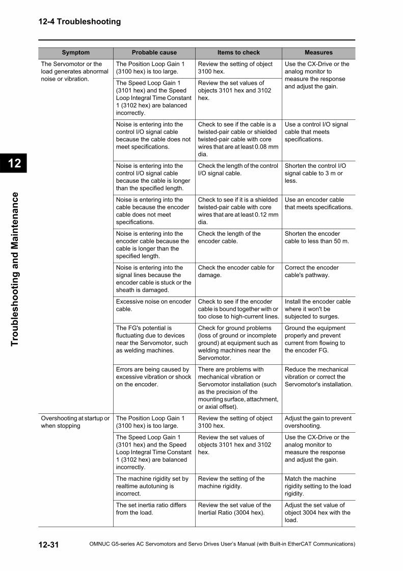
12-4 Troubleshooting
12
Trou
bles
hoot
ing
and
Mai
nten
ance
The Servomotor or the load generates abnormal noise or vibration.
The Position Loop Gain 1 (3100 hex) is too large.
Review the setting of object 3100 hex.
Use the CX-Drive or the analog monitor to measure the response and adjust the gain.The Speed Loop Gain 1
(3101 hex) and the Speed Loop Integral Time Constant 1 (3102 hex) are balanced incorrectly.
Review the set values of objects 3101 hex and 3102 hex.
Noise is entering into the control I/O signal cable because the cable does not meet specifications.
Check to see if the cable is a twisted-pair cable or shielded twisted-pair cable with core wires that are at least 0.08 mm
dia.
Use a control I/O signal cable that meets specifications.
Noise is entering into the control I/O signal cable because the cable is longer than the specified length.
Check the length of the control I/O signal cable.
Shorten the control I/O signal cable to 3 m or less.
Noise is entering into the cable because the encoder cable does not meet specifications.
Check to see if it is a shielded twisted-pair cable with core wires that are at least 0.12 mm
dia.
Use an encoder cable that meets specifications.
Noise is entering into the encoder cable because the cable is longer than the specified length.
Check the length of the encoder cable.
Shorten the encoder cable to less than 50 m.
Noise is entering into the signal lines because the encoder cable is stuck or the sheath is damaged.
Check the encoder cable for damage.
Correct the encoder cable's pathway.
Excessive noise on encoder cable.
Check to see if the encoder cable is bound together with or too close to high-current lines.
Install the encoder cable where it won't be subjected to surges.
The FG's potential is fluctuating due to devices near the Servomotor, such as welding machines.
Check for ground problems (loss of ground or incomplete ground) at equipment such as welding machines near the Servomotor.
Ground the equipment properly and prevent current from flowing to the encoder FG.
Errors are being caused by excessive vibration or shock on the encoder.
There are problems with mechanical vibration or Servomotor installation (such as the precision of the mounting surface, attachment, or axial offset).
Reduce the mechanical vibration or correct the Servomotor's installation.
Overshooting at startup or when stopping
The Position Loop Gain 1 (3100 hex) is too large.
Review the setting of object 3100 hex.
Adjust the gain to prevent overshooting.
The Speed Loop Gain 1 (3101 hex) and the Speed Loop Integral Time Constant 1 (3102 hex) are balanced incorrectly.
Review the set values of objects 3101 hex and 3102 hex.
Use the CX-Drive or the analog monitor to measure the response and adjust the gain.
The machine rigidity set by realtime autotuning is incorrect.
Review the setting of the machine rigidity.
Match the machine rigidity setting to the load rigidity.
The set inertia ratio differs from the load.
Review the set value of the Inertial Ratio (3004 hex).
Adjust the set value of object 3004 hex with the load.
Symptom Probable cause Items to check Measures
12-31 OMNUC G5-series AC Servomotors and Servo Drives User’s Manual (with Built-in EtherCAT Communications)
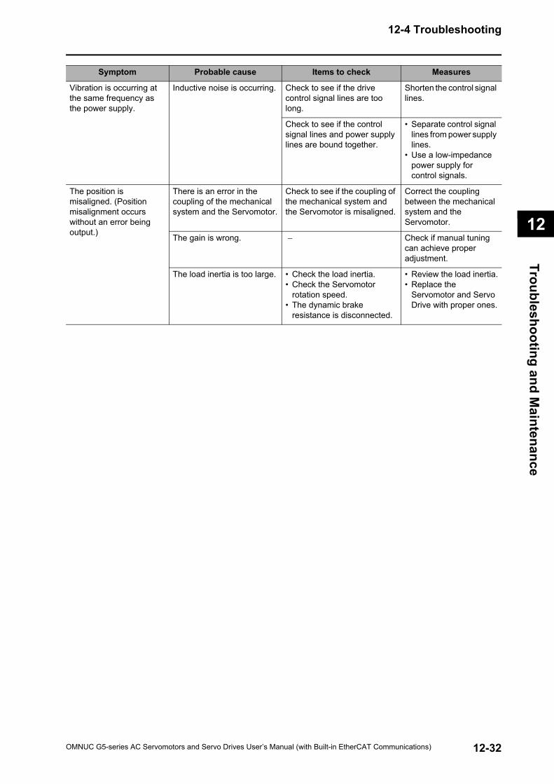
12-4 Troubleshooting
12
Troubleshooting and Maintenance
Vibration is occurring at the same frequency as the power supply.
Inductive noise is occurring. Check to see if the drive control signal lines are too long.
Shorten the control signal lines.
Check to see if the control signal lines and power supply lines are bound together.
• Separate control signal lines from power supply lines.
• Use a low-impedance power supply for control signals.
The position is misaligned. (Position misalignment occurs without an error being output.)
There is an error in the coupling of the mechanical system and the Servomotor.
Check to see if the coupling of the mechanical system and the Servomotor is misaligned.
Correct the coupling between the mechanical system and the Servomotor.
The gain is wrong. − Check if manual tuning can achieve proper adjustment.
The load inertia is too large. • Check the load inertia.• Check the Servomotor
rotation speed.• The dynamic brake
resistance is disconnected.
• Review the load inertia.• Replace the
Servomotor and Servo Drive with proper ones.
Symptom Probable cause Items to check Measures
12-32OMNUC G5-series AC Servomotors and Servo Drives User’s Manual (with Built-in EtherCAT Communications)
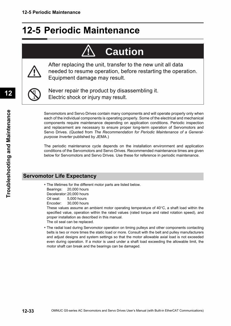
12-5 Periodic Maintenance
12
Trou
bles
hoot
ing
and
Mai
nten
ance
12-5 Periodic Maintenance
Servomotors and Servo Drives contain many components and will operate properly only wheneach of the individual components is operating properly. Some of the electrical and mechanicalcomponents require maintenance depending on application conditions. Periodic inspectionand replacement are necessary to ensure proper long-term operation of Servomotors andServo Drives. (Quoted from The Recommendation for Periodic Maintenance of a General-purpose Inverter published by JEMA.)
The periodic maintenance cycle depends on the installation environment and applicationconditions of the Servomotors and Servo Drives. Recommended maintenance times are givenbelow for Servomotors and Servo Drives. Use these for reference in periodic maintenance.
Servomotor Life ExpectancyThe lifetimes for the different motor parts are listed below.Bearings: 20,000 hoursDecelerator:20,000 hoursOil seal: 5,000 hoursEncoder: 30,000 hoursThese values assume an ambient motor operating temperature of 40°C, a shaft load within thespecified value, operation within the rated values (rated torque and rated rotation speed), andproper installation as described in this manual.The oil seal can be replaced.The radial load during Servomotor operation on timing pulleys and other components contactingbelts is two or more times the static load or more. Consult with the belt and pulley manufacturersand adjust designs and system settings so that the motor allowable axial load is not exceededeven during operation. If a motor is used under a shaft load exceeding the allowable limit, themotor shaft can break and the bearings can be damaged.
CautionAfter replacing the unit, transfer to the new unit all data needed to resume operation, before restarting the operation.Equipment damage may result.
Never repair the product by disassembling it.Electric shock or injury may result.
12-33 OMNUC G5-series AC Servomotors and Servo Drives User’s Manual (with Built-in EtherCAT Communications)
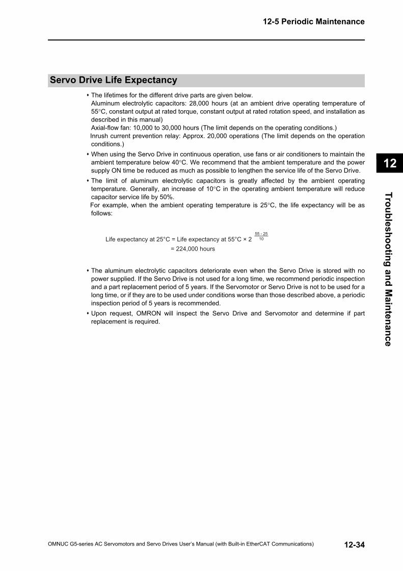
12-5 Periodic Maintenance
12
Troubleshooting and Maintenance
Servo Drive Life ExpectancyThe lifetimes for the different drive parts are given below.Aluminum electrolytic capacitors: 28,000 hours (at an ambient drive operating temperature of55°C, constant output at rated torque, constant output at rated rotation speed, and installation asdescribed in this manual)Axial-flow fan: 10,000 to 30,000 hours (The limit depends on the operating conditions.)Inrush current prevention relay: Approx. 20,000 operations (The limit depends on the operationconditions.)When using the Servo Drive in continuous operation, use fans or air conditioners to maintain theambient temperature below 40°C. We recommend that the ambient temperature and the powersupply ON time be reduced as much as possible to lengthen the service life of the Servo Drive.The limit of aluminum electrolytic capacitors is greatly affected by the ambient operatingtemperature. Generally, an increase of 10°C in the operating ambient temperature will reducecapacitor service life by 50%.For example, when the ambient operating temperature is 25°C, the life expectancy will be asfollows:
The aluminum electrolytic capacitors deteriorate even when the Servo Drive is stored with nopower supplied. If the Servo Drive is not used for a long time, we recommend periodic inspectionand a part replacement period of 5 years. If the Servomotor or Servo Drive is not to be used for along time, or if they are to be used under conditions worse than those described above, a periodicinspection period of 5 years is recommended.Upon request, OMRON will inspect the Servo Drive and Servomotor and determine if partreplacement is required.
Life expectancy at 25°C = Life expectancy at 55°C × 255 - 25
10
= 224,000 hours
12-34OMNUC G5-series AC Servomotors and Servo Drives User’s Manual (with Built-in EtherCAT Communications)
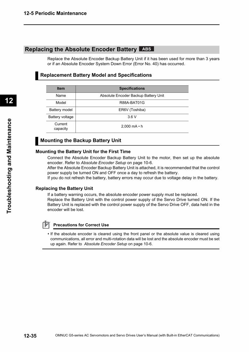
12-5 Periodic Maintenance
12
Trou
bles
hoot
ing
and
Mai
nten
ance
12-35 OMNUC G5-series AC Servomotors and Servo Drives User’s Manual (with Built-in EtherCAT Communications)
Replacing the Absolute Encoder Battery Replace the Absolute Encoder Backup Battery Unit if it has been used for more than 3 yearsor if an Absolute Encoder System Down Error (Error No. 40) has occurred.
Replacement Battery Model and Specifications
Mounting the Backup Battery Unit
Mounting the Battery Unit for the First TimeConnect the Absolute Encoder Backup Battery Unit to the motor, then set up the absoluteencoder. Refer to Absolute Encoder Setup on page 10-6.After the Absolute Encoder Backup Battery Unit is attached, it is recommended that the controlpower supply be turned ON and OFF once a day to refresh the battery.If you do not refresh the battery, battery errors may occur due to voltage delay in the battery.
Replacing the Battery UnitIf a battery warning occurs, the absolute encoder power supply must be replaced.Replace the Battery Unit with the control power supply of the Servo Drive turned ON. If theBattery Unit is replaced with the control power supply of the Servo Drive OFF, data held in theencoder will be lost.
Precautions for Correct Use
If the absolute encoder is cleared using the front panel or the absolute value is cleared usingcommunications, all error and multi-rotation data will be lost and the absolute encoder must be setup again. Refer to Absolute Encoder Setup on page 10-6.
Item Specifications
Name Absolute Encoder Backup Battery Unit
Model R88A-BAT01G
Battery model ER6V (Toshiba)
Battery voltage 3.6 V
Current capacity 2,000 mA • h
ABS
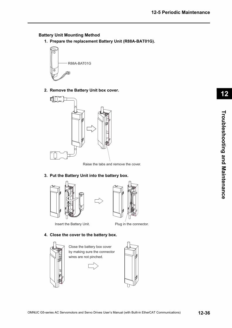
12-5 Periodic Maintenance
12
Troubleshooting and Maintenance
Battery Unit Mounting Method1. Prepare the replacement Battery Unit (R88A-BAT01G).
2. Remove the Battery Unit box cover.
3. Put the Battery Unit into the battery box.
4. Close the cover to the battery box.
R88A-BAT01G
Raise the tabs and remove the cover.
Plug in the connector.Insert the Battery Unit.
Close the battery box coverby making sure the connectorwires are not pinched.
12-36OMNUC G5-series AC Servomotors and Servo Drives User’s Manual (with Built-in EtherCAT Communications)

A
AppendixThe appendix provides a list of objects and EtherCAT terminology.
A-1 CiA402 Drive Profile ....................................................A-1A-2 Object List ..................................................................A-64A-3 EtherCAT Terminology..............................................A-81
OMNUC G5-series AC Servomotors and Servo Drives User’s Manual (with Built-in EtherCAT Communications)
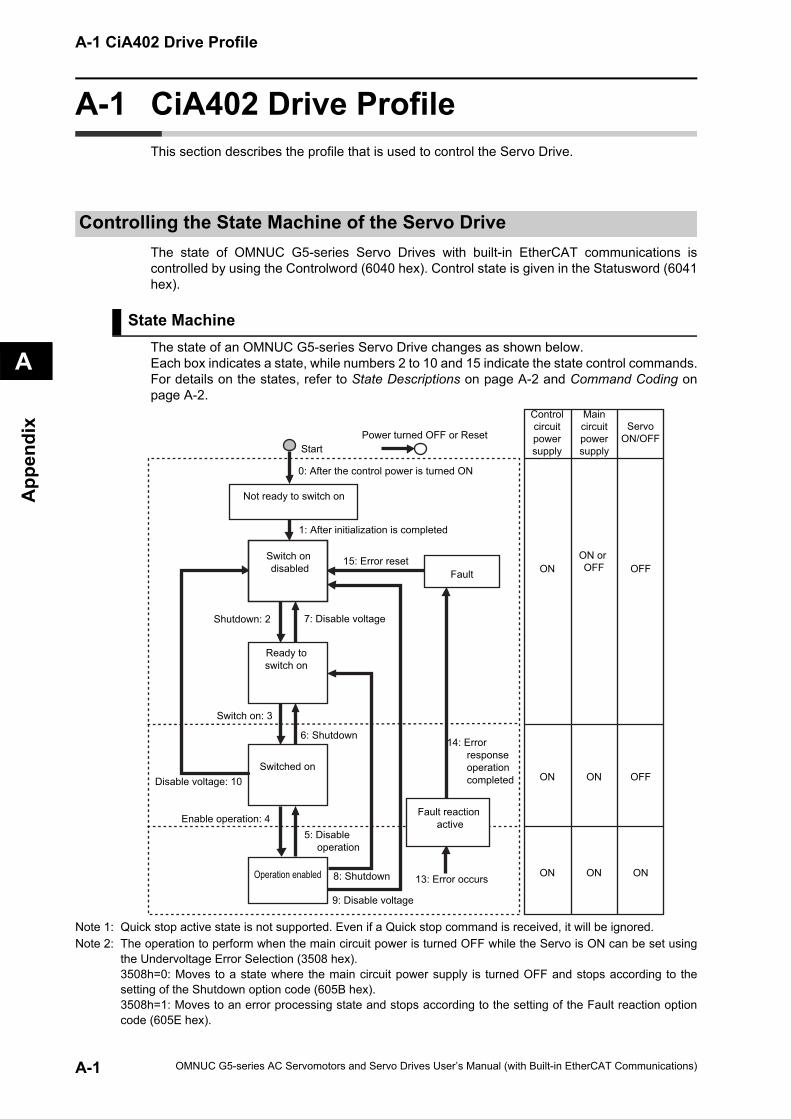
A-1 CiA402 Drive Profile
A
App
endi
x
A-1 CiA402 Drive ProfileThis section describes the profile that is used to control the Servo Drive.
Controlling the State Machine of the Servo DriveThe state of OMNUC G5-series Servo Drives with built-in EtherCAT communications iscontrolled by using the Controlword (6040 hex). Control state is given in the Statusword (6041hex).
State MachineThe state of an OMNUC G5-series Servo Drive changes as shown below.Each box indicates a state, while numbers 2 to 10 and 15 indicate the state control commands.For details on the states, refer to State Descriptions on page A-2 and Command Coding onpage A-2.
Note 1: Quick stop active state is not supported. Even if a Quick stop command is received, it will be ignored.Note 2: The operation to perform when the main circuit power is turned OFF while the Servo is ON can be set using
the Undervoltage Error Selection (3508 hex).3508h=0: Moves to a state where the main circuit power supply is turned OFF and stops according to thesetting of the Shutdown option code (605B hex).3508h=1: Moves to an error processing state and stops according to the setting of the Fault reaction optioncode (605E hex).
Power turned OFF or Reset
Not ready to switch on
1: After initialization is completed
Start
ON
ON
ON
ON
ON ON
OFF
OFFON or OFF
0: After the control power is turned ON
Switch on disabled Fault
Shutdown: 2 7: Disable voltage
Switch on: 3
Switched on
6: Shutdown
Disable voltage: 10
Enable operation: 45: Disable
operation
15: Error reset
Operation enabled 8: Shutdown
9: Disable voltage
13: Error occurs
Fault reaction active
Control circuit power supply
Main circuit power supply
Servo ON/OFF
14: Error response operation completed
Ready to switch on
A-1 OMNUC G5-series AC Servomotors and Servo Drives User’s Manual (with Built-in EtherCAT Communications)
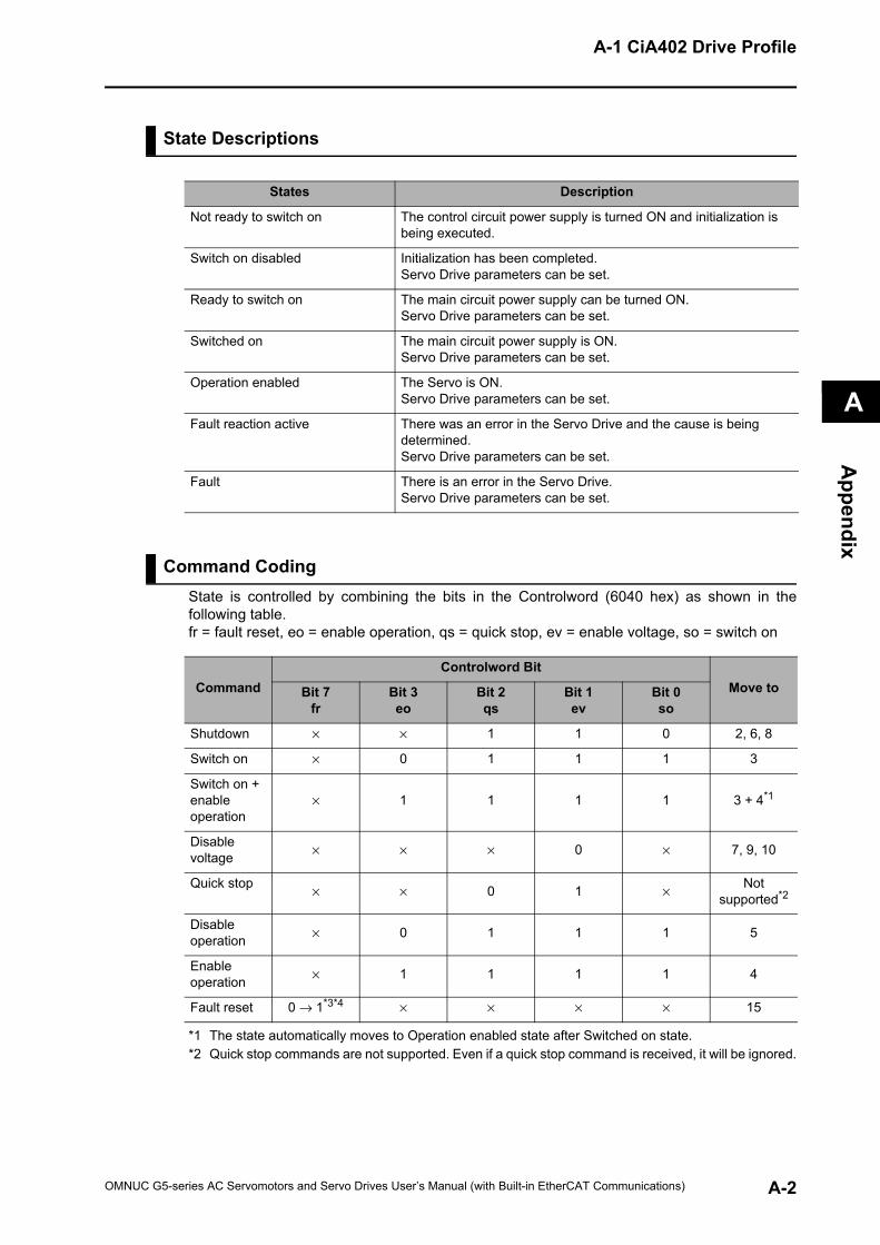
A-1 CiA402 Drive Profile
A
Appendix
State Descriptions
Command CodingState is controlled by combining the bits in the Controlword (6040 hex) as shown in thefollowing table.fr = fault reset, eo = enable operation, qs = quick stop, ev = enable voltage, so = switch on
*1 The state automatically moves to Operation enabled state after Switched on state.*2 Quick stop commands are not supported. Even if a quick stop command is received, it will be ignored.
States Description
Not ready to switch on The control circuit power supply is turned ON and initialization is being executed.
Switch on disabled Initialization has been completed.Servo Drive parameters can be set.
Ready to switch on The main circuit power supply can be turned ON.Servo Drive parameters can be set.
Switched on The main circuit power supply is ON.Servo Drive parameters can be set.
Operation enabled The Servo is ON.Servo Drive parameters can be set.
Fault reaction active There was an error in the Servo Drive and the cause is being determined.Servo Drive parameters can be set.
Fault There is an error in the Servo Drive.Servo Drive parameters can be set.
CommandControlword Bit
Move toBit 7fr
Bit 3eo
Bit 2qs
Bit 1ev
Bit 0so
Shutdown × × 1 1 0 2, 6, 8
Switch on × 0 1 1 1 3
Switch on + enable operation
× 1 1 1 1 3 + 4*1
Disable voltage × × × 0 × 7, 9, 10
Quick stop × × 0 1 × Not supported*2
Disable operation × 0 1 1 1 5
Enable operation × 1 1 1 1 4
Fault reset 0 → 1*3*4 × × × × 15
A-2OMNUC G5-series AC Servomotors and Servo Drives User’s Manual (with Built-in EtherCAT Communications)
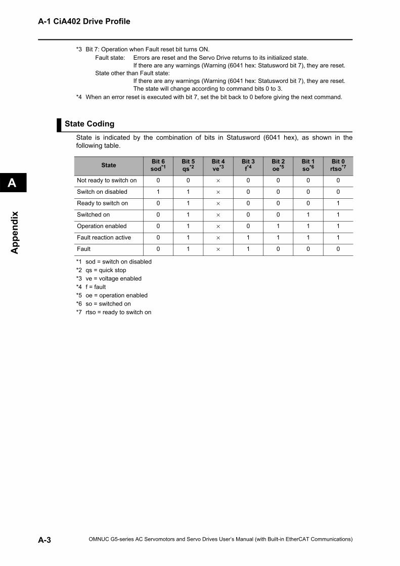
A-1 CiA402 Drive Profile
A
App
endi
x
*3 Bit 7: Operation when Fault reset bit turns ON.Fault state: Errors are reset and the Servo Drive returns to its initialized state.
If there are any warnings (Warning (6041 hex: Statusword bit 7), they are reset.State other than Fault state:
If there are any warnings (Warning (6041 hex: Statusword bit 7), they are reset.The state will change according to command bits 0 to 3.
*4 When an error reset is executed with bit 7, set the bit back to 0 before giving the next command.
State CodingState is indicated by the combination of bits in Statusword (6041 hex), as shown in thefollowing table.
*1 sod = switch on disabled*2 qs = quick stop *3 ve = voltage enabled*4 f = fault*5 oe = operation enabled*6 so = switched on*7 rtso = ready to switch on
State Bit 6sod*1
Bit 5qs*2
Bit 4ve*3
Bit 3f*4
Bit 2oe*5
Bit 1so*6
Bit 0rtso*7
Not ready to switch on 0 0 × 0 0 0 0
Switch on disabled 1 1 × 0 0 0 0
Ready to switch on 0 1 × 0 0 0 1
Switched on 0 1 × 0 0 1 1
Operation enabled 0 1 × 0 1 1 1
Fault reaction active 0 1 × 1 1 1 1
Fault 0 1 × 1 0 0 0
A-3 OMNUC G5-series AC Servomotors and Servo Drives User’s Manual (with Built-in EtherCAT Communications)
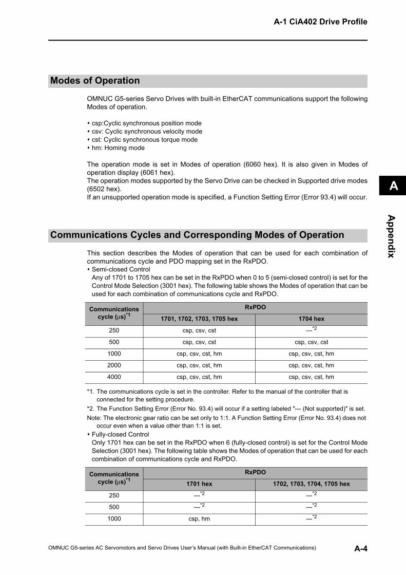
A-1 CiA402 Drive Profile
A
Appendix
Modes of Operation
OMNUC G5-series Servo Drives with built-in EtherCAT communications support the followingModes of operation.
csp:Cyclic synchronous position modecsv: Cyclic synchronous velocity modecst: Cyclic synchronous torque modehm: Homing mode
The operation mode is set in Modes of operation (6060 hex). It is also given in Modes ofoperation display (6061 hex).The operation modes supported by the Servo Drive can be checked in Supported drive modes(6502 hex).If an unsupported operation mode is specified, a Function Setting Error (Error 93.4) will occur.
Communications Cycles and Corresponding Modes of Operation
This section describes the Modes of operation that can be used for each combination ofcommunications cycle and PDO mapping set in the RxPDO.
Semi-closed ControlAny of 1701 to 1705 hex can be set in the RxPDO when 0 to 5 (semi-closed control) is set for theControl Mode Selection (3001 hex). The following table shows the Modes of operation that can beused for each combination of communications cycle and RxPDO.
*1. The communications cycle is set in the controller. Refer to the manual of the controller that is connected for the setting procedure.
*2. The Function Setting Error (Error No. 93.4) will occur if a setting labeled "--- (Not supported)" is set.Note: The electronic gear ratio can be set only to 1:1. A Function Setting Error (Error No. 93.4) does not
occur even when a value other than 1:1 is set.Fully-closed ControlOnly 1701 hex can be set in the RxPDO when 6 (fully-closed control) is set for the Control ModeSelection (3001 hex). The following table shows the Modes of operation that can be used for eachcombination of communications cycle and RxPDO.
Communications cycle (µs)*1
RxPDO
1701, 1702, 1703, 1705 hex 1704 hex
250 csp, csv, cst ---*2
500 csp, csv, cst csp, csv, cst
1000 csp, csv, cst, hm csp, csv, cst, hm
2000 csp, csv, cst, hm csp, csv, cst, hm
4000 csp, csv, cst, hm csp, csv, cst, hm
Communications cycle (µs)*1
RxPDO
1701 hex 1702, 1703, 1704, 1705 hex
250 ---*2 ---*2
500 ---*2 ---*2
1000 csp, hm ---*2
A-4OMNUC G5-series AC Servomotors and Servo Drives User’s Manual (with Built-in EtherCAT Communications)
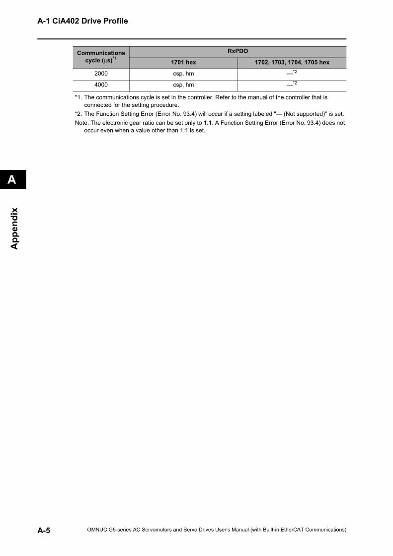
A-1 CiA402 Drive Profile
A
App
endi
x
*1. The communications cycle is set in the controller. Refer to the manual of the controller that is connected for the setting procedure.
*2. The Function Setting Error (Error No. 93.4) will occur if a setting labeled "--- (Not supported)" is set.Note: The electronic gear ratio can be set only to 1:1. A Function Setting Error (Error No. 93.4) does not
occur even when a value other than 1:1 is set.
2000 csp, hm ---*2
4000 csp, hm ---*2
Communications cycle (µs)*1
RxPDO
1701 hex 1702, 1703, 1704, 1705 hex
A-5 OMNUC G5-series AC Servomotors and Servo Drives User’s Manual (with Built-in EtherCAT Communications)
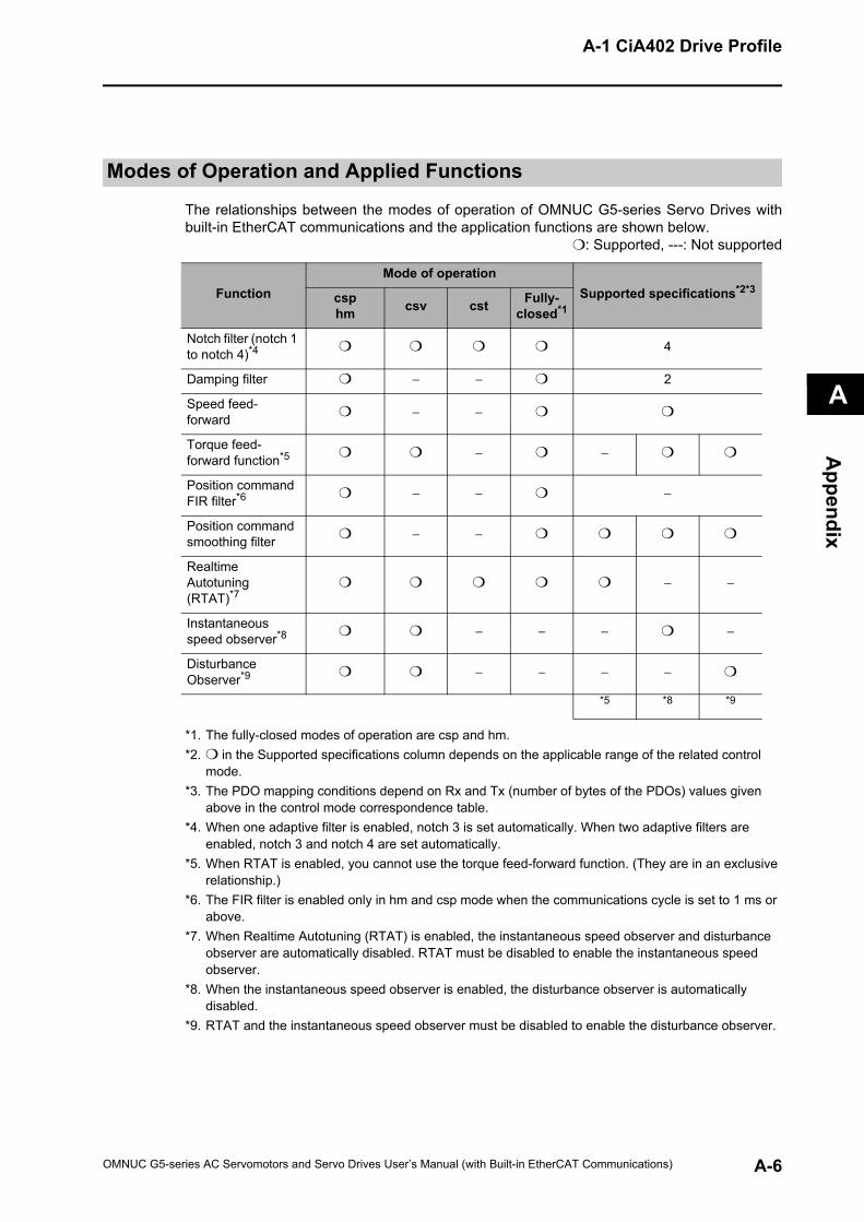
A-1 CiA402 Drive Profile
A
Appendix
Modes of Operation and Applied Functions
The relationships between the modes of operation of OMNUC G5-series Servo Drives withbuilt-in EtherCAT communications and the application functions are shown below.
: Supported, ---: Not supported
*1. The fully-closed modes of operation are csp and hm.*2. in the Supported specifications column depends on the applicable range of the related control
mode.*3. The PDO mapping conditions depend on Rx and Tx (number of bytes of the PDOs) values given
above in the control mode correspondence table.*4. When one adaptive filter is enabled, notch 3 is set automatically. When two adaptive filters are
enabled, notch 3 and notch 4 are set automatically.*5. When RTAT is enabled, you cannot use the torque feed-forward function. (They are in an exclusive
relationship.)*6. The FIR filter is enabled only in hm and csp mode when the communications cycle is set to 1 ms or
above.*7. When Realtime Autotuning (RTAT) is enabled, the instantaneous speed observer and disturbance
observer are automatically disabled. RTAT must be disabled to enable the instantaneous speed observer.
*8. When the instantaneous speed observer is enabled, the disturbance observer is automatically disabled.
*9. RTAT and the instantaneous speed observer must be disabled to enable the disturbance observer.
FunctionMode of operation
Supported specifications*2*3csphm csv cst Fully-
closed*1
Notch filter (notch 1 to notch 4)*4 4
Damping filter − − 2
Speed feed-forward − −
Torque feed-forward function*5 − −
Position command FIR filter*6 − − −
Position command smoothing filter − −
Realtime Autotuning (RTAT)*7
− −
Instantaneous speed observer*8 − − − −
Disturbance Observer*9 − − − −
*5 *8 *9
A-6OMNUC G5-series AC Servomotors and Servo Drives User’s Manual (with Built-in EtherCAT Communications)
A-1 CiA402 Drive Profile
A
App
endi
x
Changing the Mode of Operation
The operation mode of the OMNUC G5-series Servo Drives with built-in EtherCATcommunications is changed as described below.
Changing the Mode of OperationBy setting a mode of operation from the controller, the Servomotor can be operated whileswitching the control mode of the Servo Drive.The mode of operation is changed by changing the set value of Modes of operation (6060 hex).When changing the mode of operation, also change the command value of the object mappedto the RxPDO. For example, in the Cyclic synchronous position mode (csp), which is a positioncontrol mode, the Target position (607A hex) is enabled as the command value, whereas inthe Cyclic synchronous velocity mode (csv), which is a speed control mode, the Target velocity(60FF hex) is enabled as the command value. Therefore, when the mode of operation ischanged from the position control mode to the speed control mode, the enabled commandvalue is set to the Target velocity (60FF hex) at the same time.The actual mode of operation of the Servo Drive can be checked from the Modes of operationdisplay (6061 hex).Note 1: Change the operation mode while the Servomotor is stopped.
If you change the operation mode while the Servomotor is running, shock may occur in the operation of the Servomotor.
Note 2: Wait at least 2 ms before changing the mode of operation again. If you change the mode of operation again within 2 ms, a Command Error (Error No. 91.1) will occur.
Changing to an Unsupported Control ModeIf 6060 hex is set to a value other than 0 (nma), 6 (hm), 8 (csp), 9 (csv), or 10 (cst), a CommandError (Error No. 91.1) will occur.If 6060 hex is set to 9 (csv) or 10 (cst) during fully-closed control mode, a Command Error (ErrorNo. 91.1) will occur.If 6060 hex is set to 6 (hm) when the communications cycle is set to 250 or 500 µs, a FunctionSetting Error (Error No. 93.4) will occur.
Changing the Control Mode under Warning ConditionsThe operation when there is a warning for the related data (Data setting warning or Commandwarning) is different depending on the control mode.
Changing to csp, csv, or cstIf there is a warning for the related data, you cannot change to csp, csv, or cst. The currentoperation mode is maintained.Changing to hmThe operation mode changes even when there is a warning for the related data.For the hm mode, a homing error occurs instead of a warning.
Changing the Control Mode to pp or hm Mode When the Motor Is RunningWhen the Halt bit is OFF, the Servomotor comes to an immediate stop if the rising edge of 6040hex bit 4 (start bit) is not detected when the control mode is changed to pp or hm mode while themotor is running.When the Halt bit is ON, the Servomotor performs the stop operation according to the setting ofthe Halt option code (605D hex) if the rising edge of 6040 hex bit 4 (start bit) is not detected whenthe control mode is changed to pp or hm mode while the motor is running.
Precautions in hm ModeTo disable the stop process using drive prohibition when the control mode changes to hm modeduring Servomotor operation, the Servomotor is momentarily set to an immediate stop regardlessof the detection of the rising edge of 6040 hex bit 4 (start bit). However, when the Halt bit is ON,the Servomotor stops according to the setting of 605D hex.
A-7 OMNUC G5-series AC Servomotors and Servo Drives User’s Manual (with Built-in EtherCAT Communications)
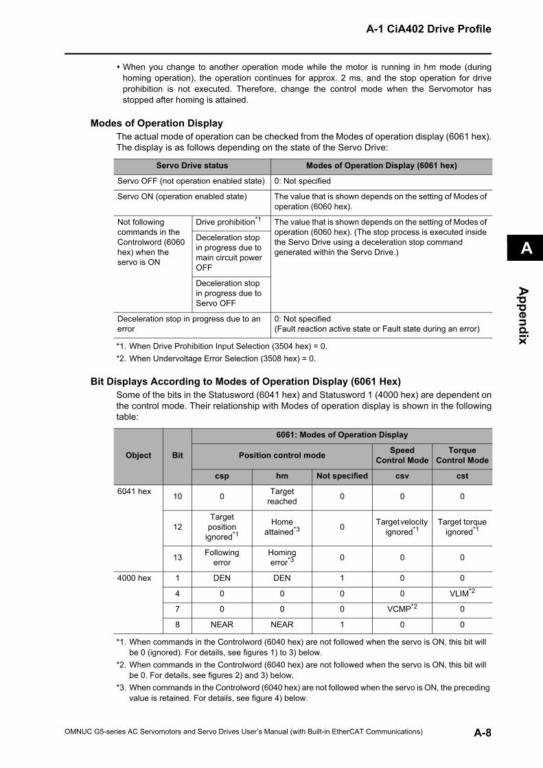
A-1 CiA402 Drive Profile
A
Appendix
When you change to another operation mode while the motor is running in hm mode (duringhoming operation), the operation continues for approx. 2 ms, and the stop operation for driveprohibition is not executed. Therefore, change the control mode when the Servomotor hasstopped after homing is attained.
Modes of Operation DisplayThe actual mode of operation can be checked from the Modes of operation display (6061 hex).The display is as follows depending on the state of the Servo Drive:
*1. When Drive Prohibition Input Selection (3504 hex) = 0.*2. When Undervoltage Error Selection (3508 hex) = 0.
Bit Displays According to Modes of Operation Display (6061 Hex)Some of the bits in the Statusword (6041 hex) and Statusword 1 (4000 hex) are dependent onthe control mode. Their relationship with Modes of operation display is shown in the followingtable:
*1. When commands in the Controlword (6040 hex) are not followed when the servo is ON, this bit will be 0 (ignored). For details, see figures 1) to 3) below.
*2. When commands in the Controlword (6040 hex) are not followed when the servo is ON, this bit will be 0. For details, see figures 2) and 3) below.
*3. When commands in the Controlword (6040 hex) are not followed when the servo is ON, the preceding value is retained. For details, see figure 4) below.
Servo Drive status Modes of Operation Display (6061 hex)
Servo OFF (not operation enabled state) 0: Not specified
Servo ON (operation enabled state) The value that is shown depends on the setting of Modes of operation (6060 hex).
Not following commands in the Controlword (6060 hex) when the servo is ON
Drive prohibition*1 The value that is shown depends on the setting of Modes of operation (6060 hex). (The stop process is executed inside the Servo Drive using a deceleration stop command generated within the Servo Drive.)
Deceleration stop in progress due to main circuit power OFF
Deceleration stop in progress due to Servo OFF
Deceleration stop in progress due to an error
0: Not specified(Fault reaction active state or Fault state during an error)
Object Bit
6061: Modes of Operation Display
Position control mode Speed Control Mode
Torque Control Mode
csp hm Not specified csv cst
6041 hex 10 0 Target reached 0 0 0
12Target
position ignored*1
Home attained*3 0 Target velocity
ignored*1Target torque
ignored*1
13 Following error
Homing error*3 0 0 0
4000 hex 1 DEN DEN 1 0 0
4 0 0 0 0 VLIM*2
7 0 0 0 VCMP*2 0
8 NEAR NEAR 1 0 0
A-8OMNUC G5-series AC Servomotors and Servo Drives User’s Manual (with Built-in EtherCAT Communications)
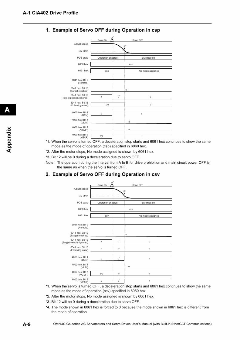
A-1 CiA402 Drive Profile
A
App
endi
x
1. Example of Servo OFF during Operation in csp
*1. When the servo is turned OFF, a deceleration stop starts and 6061 hex continues to show the same mode as the mode of operation (csp) specified in 6060 hex.
*2. After the motor stops, No mode assigned is shown by 6061 hex.*3. Bit 12 will be 0 during a deceleration due to servo OFF.Note: The operation during the interval from A to B for drive prohibition and main circuit power OFF is
the same as when the servo is turned OFF.
2. Example of Servo OFF during Operation in csv
*1. When the servo is turned OFF, a deceleration stop starts and 6061 hex continues to show the same mode as the mode of operation (csv) specified in 6060 hex.
*2. After the motor stops, No mode assigned is shown by 6061 hex.*3. Bit 12 will be 0 during a deceleration due to servo OFF.*4. The mode shown in 6061 hex is forced to 0 because the mode shown in 6061 hex is different from
the mode of operation.
Servo OFF
6061 hex
Servo ON
30 r/min
csp
Actual speed
Operation enabled Switched on
No mode assigned
0
6060 hex csp
4000 hex: Bit 7(VCMP) 0
4000 hex: Bit 8(NEAR) 1
0 1
0
(Target position ignored) 1 0
0
1
0/1
0*3
*1
0/1
(VLIM)4000 hex: Bit 4
(DEN)4000 hex: Bit 1
(Following error)6041 hex: Bit 13
6041 hex: Bit 12
(Target reached)6041 hex: Bit 10
6041 hex: Bit 9(Remote)
PDS state
A
*2B
Servo OFF
6061 hex
Servo ON
30 r/min
csv
Actual speed
Operation enabled Switched on
No mode assigned
0
6060 hex csv
4000 hex: Bit 7(VCMP) 0
4000 hex: Bit 8(NEAR) 1
0 1
0
(Target velocity ignored) 1 0
0
1
0
0*3
*1
0
0/1
(VLIM)4000 hex: Bit 4
(DEN)4000 hex: Bit 1
(Following error)6041 hex: Bit 13
6041 hex: Bit 12
(Target reached)6041 hex: Bit 10
6041 hex: Bit 9(Remote)
PDS state
A
*2B
0*4
0*4
0*4
0*4
A-9 OMNUC G5-series AC Servomotors and Servo Drives User’s Manual (with Built-in EtherCAT Communications)
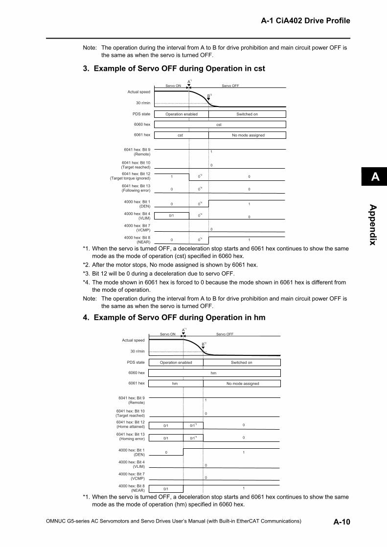
A-1 CiA402 Drive Profile
A
Appendix
Note: The operation during the interval from A to B for drive prohibition and main circuit power OFF is the same as when the servo is turned OFF.
3. Example of Servo OFF during Operation in cst
*1. When the servo is turned OFF, a deceleration stop starts and 6061 hex continues to show the same mode as the mode of operation (cst) specified in 6060 hex.
*2. After the motor stops, No mode assigned is shown by 6061 hex.*3. Bit 12 will be 0 during a deceleration due to servo OFF.*4. The mode shown in 6061 hex is forced to 0 because the mode shown in 6061 hex is different from
the mode of operation.Note: The operation during the interval from A to B for drive prohibition and main circuit power OFF is
the same as when the servo is turned OFF.
4. Example of Servo OFF during Operation in hm
*1. When the servo is turned OFF, a deceleration stop starts and 6061 hex continues to show the same mode as the mode of operation (hm) specified in 6060 hex.
Servo OFF
6061 hex
Servo ON
30 r/min
cst
Actual speed
Operation enabled Switched on
No mode assigned
0
6060 hex cst
4000 hex: Bit 7(VCMP)
4000 hex: Bit 8(NEAR) 1
0 1
0
0
(Target torque ignored) 1 0
0
1
0
0*3
*1
0
(VLIM)4000 hex: Bit 4
(DEN)4000 hex: Bit 1
(Following error)6041 hex: Bit 13
6041 hex: Bit 12
(Target reached)6041 hex: Bit 10
6041 hex: Bit 9(Remote)
PDS state
A
*2B
0*4
0*4
0/1 0*4
0*4
Servo OFF
6061 hex
Servo ON
30 r/min
hm
Actual speed
Operation enabled Switched on
No mode assigned
0
6060 hex hm
4000 hex: Bit 7(VCMP)
4000 hex: Bit 8(NEAR) 1
0 1
0
0
(Home attained) 0/1 0
0
1
0/1
0/1*3
*1
0/1
(VLIM)4000 hex: Bit 4
(DEN)4000 hex: Bit 1
(Homing error)6041 hex: Bit 13
6041 hex: Bit 12
(Target reached)6041 hex: Bit 10
6041 hex: Bit 9(Remote)
PDS state
A
*2B
0/1*3
A-10OMNUC G5-series AC Servomotors and Servo Drives User’s Manual (with Built-in EtherCAT Communications)
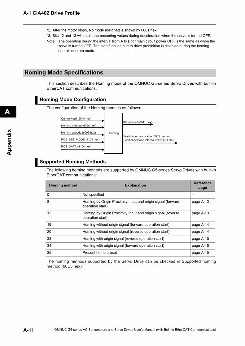
A-1 CiA402 Drive Profile
A
App
endi
x
*2. After the motor stops, No mode assigned is shown by 6061 hex.*3. Bits 12 and 13 will retain the preceding values during deceleration when the servo is turned OFF.Note: The operation during the interval from A to B for main circuit power OFF is the same as when the
servo is turned OFF. The stop function due to drive prohibition is disabled during the homing operation in hm mode.
Homing Mode Specifications
This section describes the Homing mode of the OMNUC G5-series Servo Drives with built-inEtherCAT communications.
Homing Mode ConfigurationThe configuration of the Homing mode is as follows:
Supported Homing MethodsThe following homing methods are supported by OMNUC G5-series Servo Drives with built-inEtherCAT communications:
The homing methods supported by the Servo Drive can be checked in Supported homingmethod (60E3 hex).
Homing method Explanation Reference page
0 Not specified −
8 Homing by Origin Proximity Input and origin signal (forward operation start)
page A-13
12 Homing by Origin Proximity Input and origin signal (reverse operation start)
page A-13
19 Homing without origin signal (forward operation start) page A-14
20 Homing without origin signal (reverse operation start) page A-14
33 Homing with origin signal (reverse operation start) page A-15
34 Homing with origin signal (forward operation start) page A-15
35 Present home preset page A-15
Controlword (6040 hex)
Homing method (6098 hex)
Homing speeds (6099 hex)
Statusword (6041 hex)
POS_SET_MODE (4103 hex)
POS_DATA (4104 hex)
Positiondemand value (6062 hex) or Positiondemand internal value (60FCh)
Homing
A-11 OMNUC G5-series AC Servomotors and Servo Drives User’s Manual (with Built-in EtherCAT Communications)
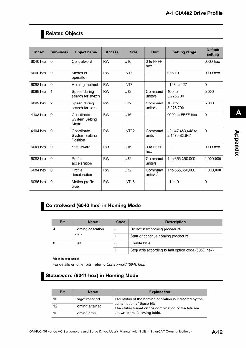
A-1 CiA402 Drive Profile
A
Appendix
Related Objects
Controlword (6040 hex) in Homing Mode
Bit 6 is not used.For details on other bits, refer to Controlword (6040 hex).
Statusword (6041 hex) in Homing Mode
Index Sub-index Object name Access Size Unit Setting range Default setting
6040 hex 0 Controlword RW U16 0 to FFFF hex
− 0000 hex
6060 hex 0 Modes of operation
RW INT8 − 0 to 10 0000 hex
6098 hex 0 Homing method RW INT8 − −128 to 127 0
6099 hex 1 Speed during search for switch
RW U32 Command units/s
100 to 3,276,700
5,000
6099 hex 2 Speed during search for zero
RW U32 Command units/s
100 to 3,276,700
5,000
4103 hex 0 Coordinate System Setting Mode
RW U16 − 0000 to FFFF hex 0
4104 hex 0 Coordinate System Setting Position
RW INT32 Command units
−2,147,483,648 to 2,147,483,647
0
6041 hex 0 Statusword RO U16 0 to FFFF hex
− 0000 hex
6083 hex 0 Profile acceleration
RW U32 Command units/s2
1 to 655,350,000 1,000,000
6084 hex 0 Profile deceleration
RW U32 Command units/s2
1 to 655,350,000 1,000,000
6086 hex 0 Motion profile type
RW INT16 − −1 to 0 0
Bit Name Code Description
4 Homing operation start
0 Do not start homing procedure.
1 Start or continue homing procedure.
8 Halt 0 Enable bit 4
1 Stop axis according to halt option code (605D hex)
Bit Name Explanation
10 Target reached The status of the homing operation is indicated by the combination of these bits.The status based on the combination of the bits are shown in the following table.
12 Homing attained
13 Homing error
A-12OMNUC G5-series AC Servomotors and Servo Drives User’s Manual (with Built-in EtherCAT Communications)
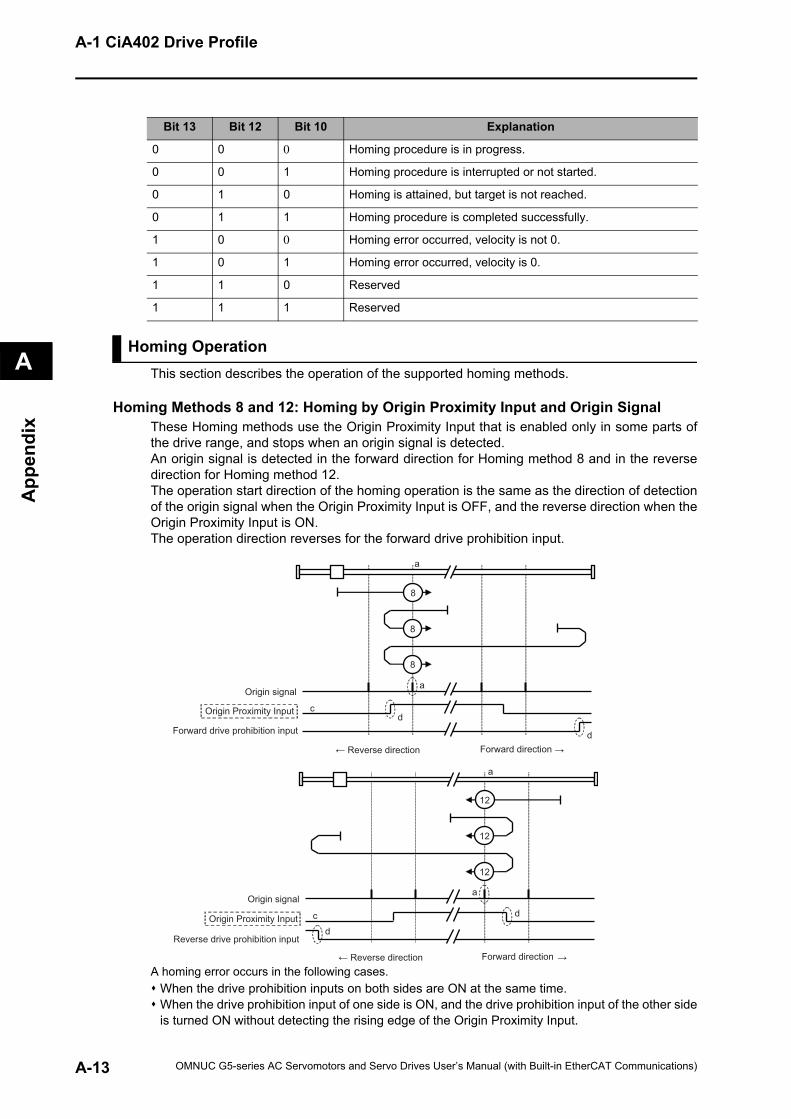
A-1 CiA402 Drive Profile
A
App
endi
x
Homing OperationThis section describes the operation of the supported homing methods.
Homing Methods 8 and 12: Homing by Origin Proximity Input and Origin SignalThese Homing methods use the Origin Proximity Input that is enabled only in some parts ofthe drive range, and stops when an origin signal is detected.An origin signal is detected in the forward direction for Homing method 8 and in the reversedirection for Homing method 12.The operation start direction of the homing operation is the same as the direction of detectionof the origin signal when the Origin Proximity Input is OFF, and the reverse direction when theOrigin Proximity Input is ON.The operation direction reverses for the forward drive prohibition input.
A homing error occurs in the following cases.When the drive prohibition inputs on both sides are ON at the same time.When the drive prohibition input of one side is ON, and the drive prohibition input of the other sideis turned ON without detecting the rising edge of the Origin Proximity Input.
Bit 13 Bit 12 Bit 10 Explanation
0 0 0 Homing procedure is in progress.
0 0 1 Homing procedure is interrupted or not started.
0 1 0 Homing is attained, but target is not reached.
0 1 1 Homing procedure is completed successfully.
1 0 0 Homing error occurred, velocity is not 0.
1 0 1 Homing error occurred, velocity is 0.
1 1 0 Reserved
1 1 1 Reserved
Origin signal
Origin Proximity Input
Forward drive prohibition input
8
8
8
a
cd
d
a
← Reverse direction Forward direction →
Origin signal
Origin Proximity Input
Reverse drive prohibition input
c
← Reverse direction Forward direction →
12
12
12
a
d
d
a
A-13 OMNUC G5-series AC Servomotors and Servo Drives User’s Manual (with Built-in EtherCAT Communications)
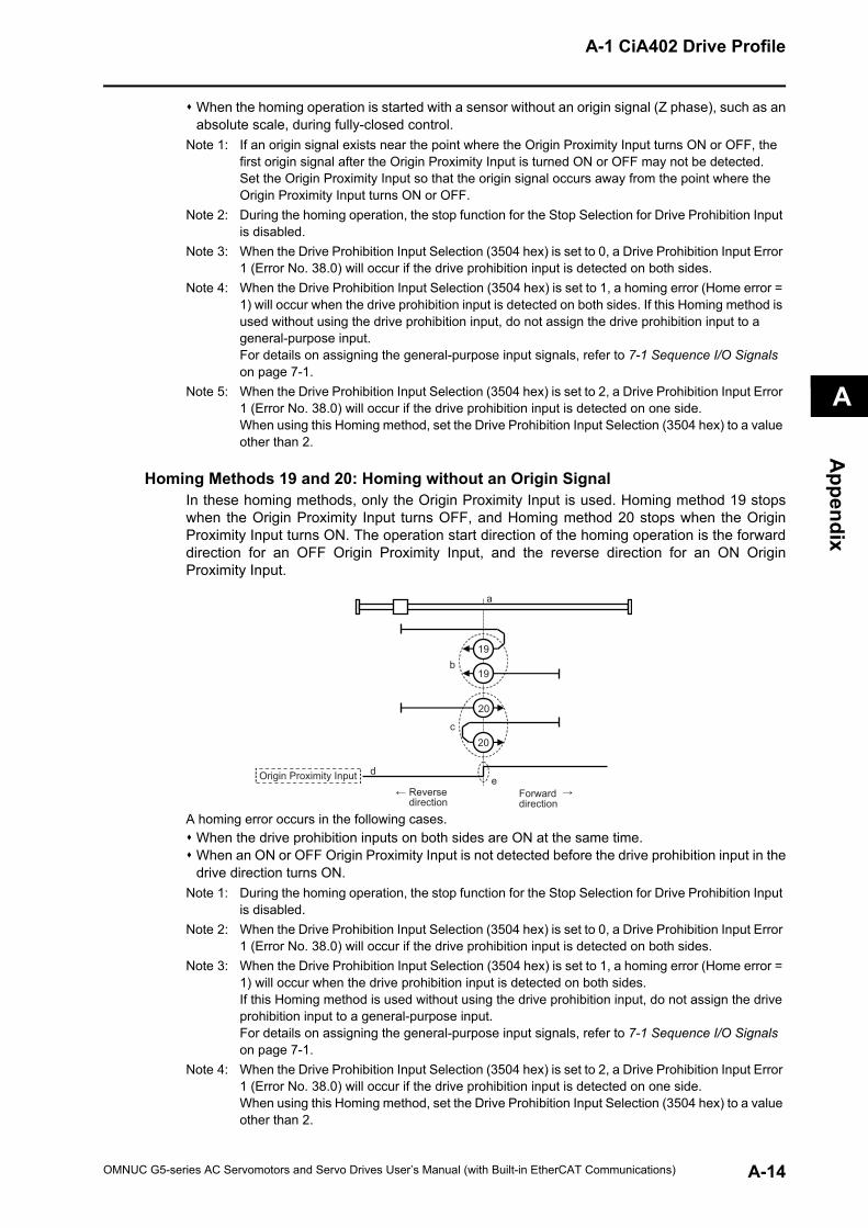
A-1 CiA402 Drive Profile
A
Appendix
When the homing operation is started with a sensor without an origin signal (Z phase), such as anabsolute scale, during fully-closed control.
Note 1: If an origin signal exists near the point where the Origin Proximity Input turns ON or OFF, the first origin signal after the Origin Proximity Input is turned ON or OFF may not be detected.Set the Origin Proximity Input so that the origin signal occurs away from the point where the Origin Proximity Input turns ON or OFF.
Note 2: During the homing operation, the stop function for the Stop Selection for Drive Prohibition Input is disabled.
Note 3: When the Drive Prohibition Input Selection (3504 hex) is set to 0, a Drive Prohibition Input Error 1 (Error No. 38.0) will occur if the drive prohibition input is detected on both sides.
Note 4: When the Drive Prohibition Input Selection (3504 hex) is set to 1, a homing error (Home error = 1) will occur when the drive prohibition input is detected on both sides. If this Homing method is used without using the drive prohibition input, do not assign the drive prohibition input to a general-purpose input.For details on assigning the general-purpose input signals, refer to 7-1 Sequence I/O Signals on page 7-1.
Note 5: When the Drive Prohibition Input Selection (3504 hex) is set to 2, a Drive Prohibition Input Error 1 (Error No. 38.0) will occur if the drive prohibition input is detected on one side.When using this Homing method, set the Drive Prohibition Input Selection (3504 hex) to a value other than 2.
Homing Methods 19 and 20: Homing without an Origin SignalIn these homing methods, only the Origin Proximity Input is used. Homing method 19 stopswhen the Origin Proximity Input turns OFF, and Homing method 20 stops when the OriginProximity Input turns ON. The operation start direction of the homing operation is the forwarddirection for an OFF Origin Proximity Input, and the reverse direction for an ON OriginProximity Input.
A homing error occurs in the following cases.When the drive prohibition inputs on both sides are ON at the same time.When an ON or OFF Origin Proximity Input is not detected before the drive prohibition input in thedrive direction turns ON.
Note 1: During the homing operation, the stop function for the Stop Selection for Drive Prohibition Input is disabled.
Note 2: When the Drive Prohibition Input Selection (3504 hex) is set to 0, a Drive Prohibition Input Error 1 (Error No. 38.0) will occur if the drive prohibition input is detected on both sides.
Note 3: When the Drive Prohibition Input Selection (3504 hex) is set to 1, a homing error (Home error = 1) will occur when the drive prohibition input is detected on both sides.If this Homing method is used without using the drive prohibition input, do not assign the drive prohibition input to a general-purpose input.For details on assigning the general-purpose input signals, refer to 7-1 Sequence I/O Signals on page 7-1.
Note 4: When the Drive Prohibition Input Selection (3504 hex) is set to 2, a Drive Prohibition Input Error 1 (Error No. 38.0) will occur if the drive prohibition input is detected on one side.When using this Homing method, set the Drive Prohibition Input Selection (3504 hex) to a value other than 2.
Origin Proximity Input
20
20
de
a
19
19b
c
← Reverse direction
Forward direction
→
A-14OMNUC G5-series AC Servomotors and Servo Drives User’s Manual (with Built-in EtherCAT Communications)
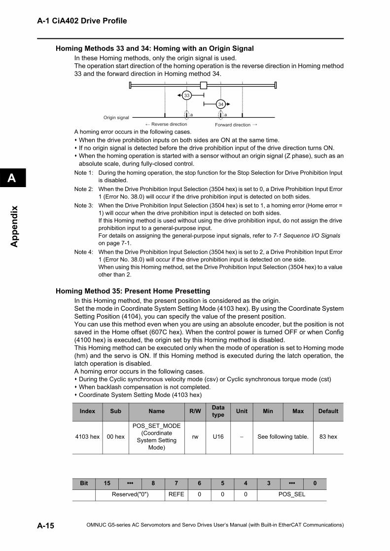
A-1 CiA402 Drive Profile
A
App
endi
x
Homing Methods 33 and 34: Homing with an Origin SignalIn these Homing methods, only the origin signal is used.The operation start direction of the homing operation is the reverse direction in Homing method33 and the forward direction in Homing method 34.
A homing error occurs in the following cases.When the drive prohibition inputs on both sides are ON at the same time.If no origin signal is detected before the drive prohibition input of the drive direction turns ON.When the homing operation is started with a sensor without an origin signal (Z phase), such as anabsolute scale, during fully-closed control.
Note 1: During the homing operation, the stop function for the Stop Selection for Drive Prohibition Input is disabled.
Note 2: When the Drive Prohibition Input Selection (3504 hex) is set to 0, a Drive Prohibition Input Error 1 (Error No. 38.0) will occur if the drive prohibition input is detected on both sides.
Note 3: When the Drive Prohibition Input Selection (3504 hex) is set to 1, a homing error (Home error = 1) will occur when the drive prohibition input is detected on both sides.If this Homing method is used without using the drive prohibition input, do not assign the drive prohibition input to a general-purpose input.For details on assigning the general-purpose input signals, refer to 7-1 Sequence I/O Signals on page 7-1.
Note 4: When the Drive Prohibition Input Selection (3504 hex) is set to 2, a Drive Prohibition Input Error 1 (Error No. 38.0) will occur if the drive prohibition input is detected on one side.When using this Homing method, set the Drive Prohibition Input Selection (3504 hex) to a value other than 2.
Homing Method 35: Present Home PresettingIn this Homing method, the present position is considered as the origin.Set the mode in Coordinate System Setting Mode (4103 hex). By using the Coordinate SystemSetting Position (4104), you can specify the value of the present position.You can use this method even when you are using an absolute encoder, but the position is notsaved in the Home offset (607C hex). When the control power is turned OFF or when Config(4100 hex) is executed, the origin set by this Homing method is disabled.This Homing method can be executed only when the mode of operation is set to Homing mode(hm) and the servo is ON. If this Homing method is executed during the latch operation, thelatch operation is disabled.A homing error occurs in the following cases.
During the Cyclic synchronous velocity mode (csv) or Cyclic synchronous torque mode (cst)When backlash compensation is not completed.Coordinate System Setting Mode (4103 hex)
Index Sub Name R/W Data type Unit Min Max Default
4103 hex 00 hex
POS_SET_MODE (Coordinate
System Setting Mode)
rw U16 − See following table. 83 hex
Bit 15 ••• 8 7 6 5 4 3 ••• 0
Reserved("0") REFE 0 0 0 POS_SEL
Origin signal
33
a
34
a
← Reverse direction Forward direction →
A-15 OMNUC G5-series AC Servomotors and Servo Drives User’s Manual (with Built-in EtherCAT Communications)
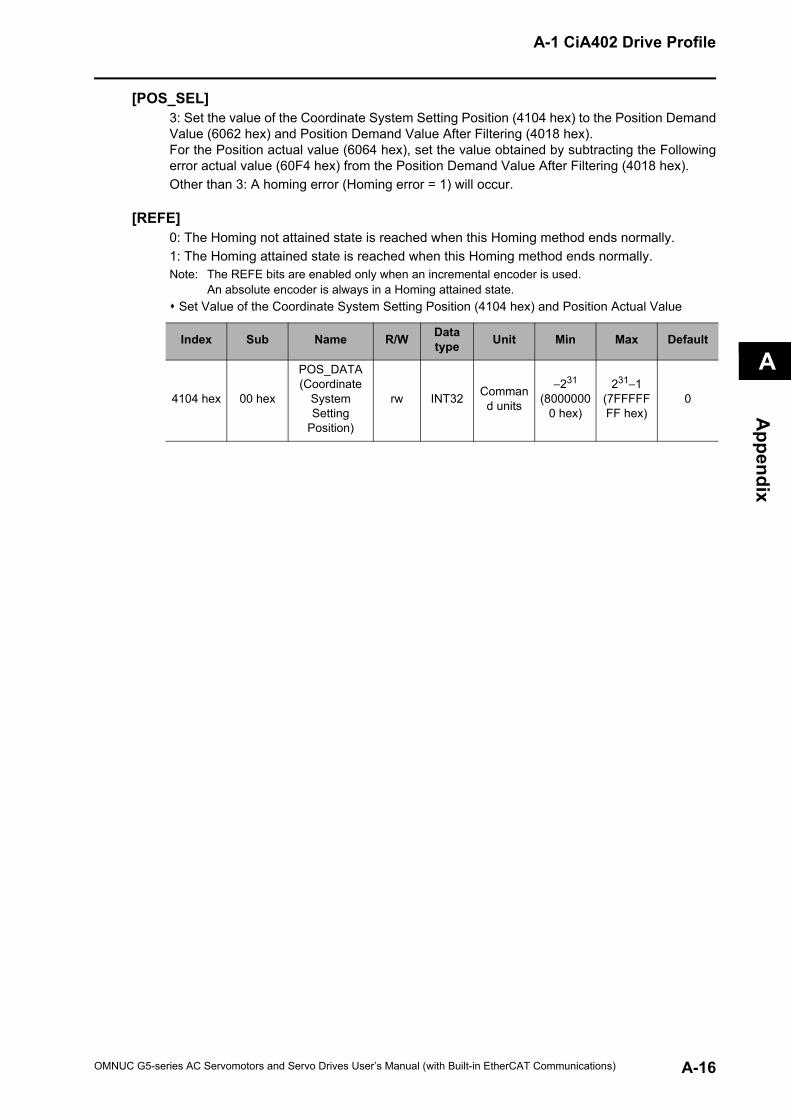
A-1 CiA402 Drive Profile
A
Appendix
[POS_SEL]3: Set the value of the Coordinate System Setting Position (4104 hex) to the Position DemandValue (6062 hex) and Position Demand Value After Filtering (4018 hex).For the Position actual value (6064 hex), set the value obtained by subtracting the Followingerror actual value (60F4 hex) from the Position Demand Value After Filtering (4018 hex).Other than 3: A homing error (Homing error = 1) will occur.
[REFE]0: The Homing not attained state is reached when this Homing method ends normally.1: The Homing attained state is reached when this Homing method ends normally.Note: The REFE bits are enabled only when an incremental encoder is used.
An absolute encoder is always in a Homing attained state.Set Value of the Coordinate System Setting Position (4104 hex) and Position Actual Value
Index Sub Name R/W Data type Unit Min Max Default
4104 hex 00 hex
POS_DATA (Coordinate
System Setting
Position)
rw INT32 Command units
−231
(80000000 hex)
231−1(7FFFFFFF hex)
0
A-16OMNUC G5-series AC Servomotors and Servo Drives User’s Manual (with Built-in EtherCAT Communications)
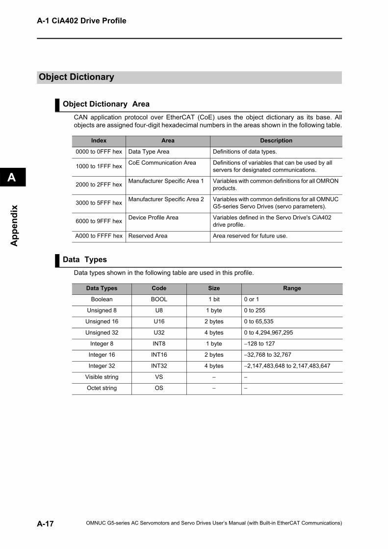
A-1 CiA402 Drive Profile
A
App
endi
x
Object Dictionary
Object Dictionary AreaCAN application protocol over EtherCAT (CoE) uses the object dictionary as its base. Allobjects are assigned four-digit hexadecimal numbers in the areas shown in the following table.
Data TypesData types shown in the following table are used in this profile.
Index Area Description
0000 to 0FFF hex Data Type Area Definitions of data types.
1000 to 1FFF hex CoE Communication Area Definitions of variables that can be used by all servers for designated communications.
2000 to 2FFF hex Manufacturer Specific Area 1 Variables with common definitions for all OMRON products.
3000 to 5FFF hex Manufacturer Specific Area 2 Variables with common definitions for all OMNUC G5-series Servo Drives (servo parameters).
6000 to 9FFF hex Device Profile Area Variables defined in the Servo Drive's CiA402 drive profile.
A000 to FFFF hex Reserved Area Area reserved for future use.
Data Types Code Size Range
Boolean BOOL 1 bit 0 or 1
Unsigned 8 U8 1 byte 0 to 255
Unsigned 16 U16 2 bytes 0 to 65,535
Unsigned 32 U32 4 bytes 0 to 4,294,967,295
Integer 8 INT8 1 byte −128 to 127
Integer 16 INT16 2 bytes −32,768 to 32,767
Integer 32 INT32 4 bytes −2,147,483,648 to 2,147,483,647
Visible string VS − −
Octet string OS − −
A-17 OMNUC G5-series AC Servomotors and Servo Drives User’s Manual (with Built-in EtherCAT Communications)
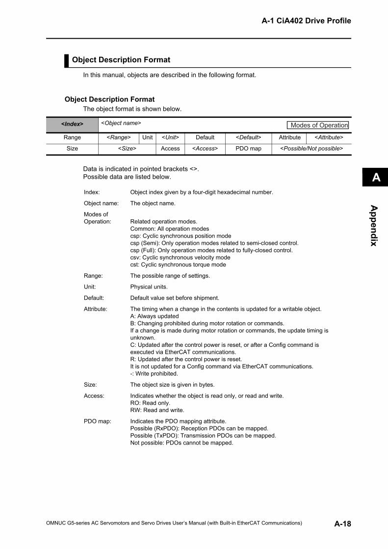
A-1 CiA402 Drive Profile
A
Appendix
Object Description Format
In this manual, objects are described in the following format.
Object Description FormatThe object format is shown below.
Data is indicated in pointed brackets <>.Possible data are listed below.
<Index> <Object name>
Range <Range> Unit <Unit> Default <Default> Attribute <Attribute>
Size <Size> Access <Access> PDO map <Possible/Not possible>
Modes of Operation
Index: Object index given by a four-digit hexadecimal number.
Object name: The object name.
Modes of Operation: Related operation modes.
Common: All operation modescsp: Cyclic synchronous position modecsp (Semi): Only operation modes related to semi-closed control.csp (Full): Only operation modes related to fully-closed control.csv: Cyclic synchronous velocity modecst: Cyclic synchronous torque mode
Range: The possible range of settings.
Unit: Physical units.
Default: Default value set before shipment.
Attribute: The timing when a change in the contents is updated for a writable object.A: Always updatedB: Changing prohibited during motor rotation or commands.If a change is made during motor rotation or commands, the update timing is unknown.C: Updated after the control power is reset, or after a Config command is executed via EtherCAT communications.R: Updated after the control power is reset.It is not updated for a Config command via EtherCAT communications.-: Write prohibited.
Size: The object size is given in bytes.
Access: Indicates whether the object is read only, or read and write.RO: Read only.RW: Read and write.
PDO map: Indicates the PDO mapping attribute.Possible (RxPDO): Reception PDOs can be mapped.Possible (TxPDO): Transmission PDOs can be mapped.Not possible: PDOs cannot be mapped.
A-18OMNUC G5-series AC Servomotors and Servo Drives User’s Manual (with Built-in EtherCAT Communications)
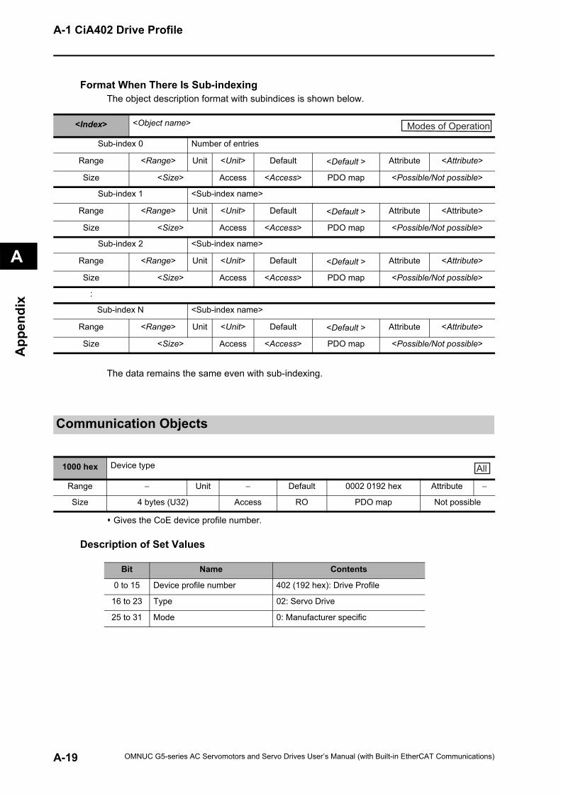
A-1 CiA402 Drive Profile
A
App
endi
x
Format When There Is Sub-indexingThe object description format with subindices is shown below.
The data remains the same even with sub-indexing.
Communication Objects
Gives the CoE device profile number.
Description of Set Values
<Index> <Object name>
Sub-index 0 Number of entries
Range <Range> Unit <Unit> Default <Default > Attribute <Attribute>
Size <Size> Access <Access> PDO map <Possible/Not possible>
Sub-index 1 <Sub-index name>
Range <Range> Unit <Unit> Default <Default > Attribute <Attribute>
Size <Size> Access <Access> PDO map <Possible/Not possible>
Sub-index 2 <Sub-index name>
Range <Range> Unit <Unit> Default <Default > Attribute <Attribute>
Size <Size> Access <Access> PDO map <Possible/Not possible>
:
Sub-index N <Sub-index name>
Range <Range> Unit <Unit> Default <Default > Attribute <Attribute>
Size <Size> Access <Access> PDO map <Possible/Not possible>
Modes of Operation
1000 hex Device type
Range − Unit − Default 0002 0192 hex Attribute −
Size 4 bytes (U32) Access RO PDO map Not possible
All
Bit Name Contents
0 to 15 Device profile number 402 (192 hex): Drive Profile
16 to 23 Type 02: Servo Drive
25 to 31 Mode 0: Manufacturer specific
A-19 OMNUC G5-series AC Servomotors and Servo Drives User’s Manual (with Built-in EtherCAT Communications)
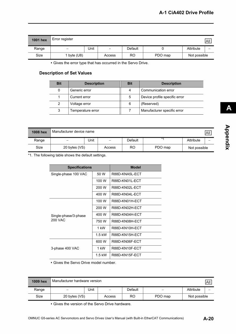
A-1 CiA402 Drive Profile
A
Appendix
Gives the error type that has occurred in the Servo Drive.
Description of Set Values
Gives the Servo Drive model number.
Gives the version of the Servo Drive hardware.
1001 hex Error register
Range − Unit - Default 0 Attribute −
Size 1 byte (U8) Access RO PDO map Not possible
All
Bit Description Bit Description
0 Generic error 4 Communication error
1 Current error 5 Device profile specific error
2 Voltage error 6 (Reserved)
3 Temperature error 7 Manufacturer specific error
1008 hex Manufacturer device name
Range − Unit − Default *1 Attribute −
Size 20 bytes (VS) Access RO PDO map Not possible
*1. The following table shows the default settings.
All
Specifications Model
Single-phase 100 VAC 50 W R88D-KNA5L-ECT
100 W R88D-KN01L-ECT
200 W R88D-KN02L-ECT
400 W R88D-KN04L-ECT
Single-phase/3-phase 200 VAC
100 W R88D-KN01H-ECT
200 W R88D-KN02H-ECT
400 W R88D-KN04H-ECT
750 W R88D-KN08H-ECT
1 kW R88D-KN10H-ECT
1.5 kW R88D-KN15H-ECT
3-phase 400 VAC
600 W R88D-KN06F-ECT
1 kW R88D-KN10F-ECT
1.5 kW R88D-KN15F-ECT
1009 hex Manufacturer hardware version
Range − Unit − Default − Attribute −
Size 20 bytes (VS) Access RO PDO map Not possible
All
A-20OMNUC G5-series AC Servomotors and Servo Drives User’s Manual (with Built-in EtherCAT Communications)
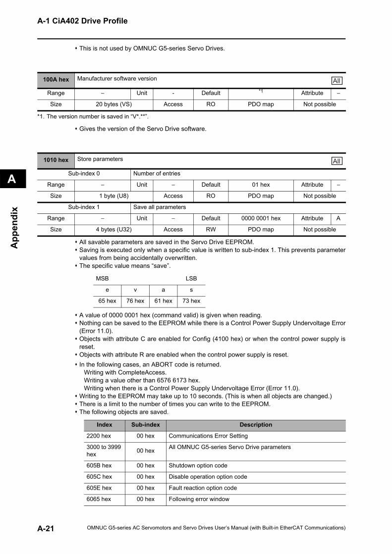
A-1 CiA402 Drive Profile
A
App
endi
x
This is not used by OMNUC G5-series Servo Drives.
Gives the version of the Servo Drive software.
All savable parameters are saved in the Servo Drive EEPROM.Saving is executed only when a specific value is written to sub-index 1. This prevents parametervalues from being accidentally overwritten.The specific value means “save”.
A value of 0000 0001 hex (command valid) is given when reading.Nothing can be saved to the EEPROM while there is a Control Power Supply Undervoltage Error(Error 11.0).Objects with attribute C are enabled for Config (4100 hex) or when the control power supply isreset.Objects with attribute R are enabled when the control power supply is reset.In the following cases, an ABORT code is returned.
Writing with CompleteAccess.Writing a value other than 6576 6173 hex.Writing when there is a Control Power Supply Undervoltage Error (Error 11.0).
Writing to the EEPROM may take up to 10 seconds. (This is when all objects are changed.)There is a limit to the number of times you can write to the EEPROM.The following objects are saved.
100A hex Manufacturer software version
Range − Unit - Default *1 Attribute −
Size 20 bytes (VS) Access RO PDO map Not possible
*1. The version number is saved in “V*.**”.
All
1010 hex Store parameters
Sub-index 0 Number of entries
Range − Unit − Default 01 hex Attribute −
Size 1 byte (U8) Access RO PDO map Not possible
Sub-index 1 Save all parameters
Range − Unit − Default 0000 0001 hex Attribute A
Size 4 bytes (U32) Access RW PDO map Not possible
All
MSB LSB
e v a s
65 hex 76 hex 61 hex 73 hex
Index Sub-index Description
2200 hex 00 hex Communications Error Setting
3000 to 3999 hex 00 hex All OMNUC G5-series Servo Drive parameters
605B hex 00 hex Shutdown option code
605C hex 00 hex Disable operation option code
605E hex 00 hex Fault reaction option code
6065 hex 00 hex Following error window
A-21 OMNUC G5-series AC Servomotors and Servo Drives User’s Manual (with Built-in EtherCAT Communications)
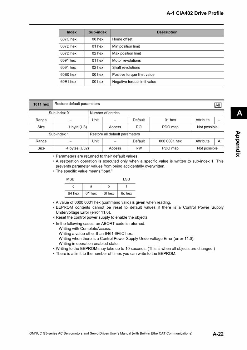
A-1 CiA402 Drive Profile
A
Appendix
Parameters are returned to their default values.A restoration operation is executed only when a specific value is written to sub-index 1. Thisprevents parameter values from being accidentally overwritten.The specific value means “load.”
A value of 0000 0001 hex (command valid) is given when reading.EEPROM contents cannot be reset to default values if there is a Control Power SupplyUndervoltage Error (error 11.0).Reset the control power supply to enable the objects.In the following cases, an ABORT code is returned.
Writing with CompleteAccess.Writing a value other than 6461 6F6C hex.Writing when there is a Control Power Supply Undervoltage Error (error 11.0).Writing in operation enabled state.
Writing to the EEPROM may take up to 10 seconds. (This is when all objects are changed.)There is a limit to the number of times you can write to the EEPROM.
607C hex 00 hex Home offset
607D hex 01 hex Min position limit
607D hex 02 hex Max position limit
6091 hex 01 hex Motor revolutions
6091 hex 02 hex Shaft revolutions
60E0 hex 00 hex Positive torque limit value
60E1 hex 00 hex Negative torque limit value
Index Sub-index Description
1011 hex Restore default parameters
Sub-index 0 Number of entries
Range − Unit − Default 01 hex Attribute −
Size 1 byte (U8) Access RO PDO map Not possible
Sub-index 1 Restore all default parameters
Range − Unit − Default 000 0001 hex Attribute A
Size 4 bytes (U32) Access RW PDO map Not possible
All
MSB LSB
d a o l
64 hex 61 hex 6f hex 6c hex
A-22OMNUC G5-series AC Servomotors and Servo Drives User’s Manual (with Built-in EtherCAT Communications)
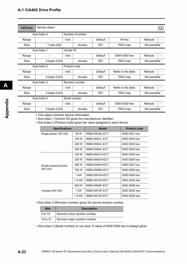
A-1 CiA402 Drive Profile
A
App
endi
x
This object contains device information.Sub-index 1 (Vendor ID) gives the manufacturer identifier.Sub-index 2 (Product code) gives the value assigned to each device.
Sub-index 3 (Revision number) gives the device revision number.
Sub-index 4 (Serial number) is not used. A value of 0000 0000 hex is always given.
1018 hex Identity object
Sub-index 0 Number of entries
Range − Unit − Default 04 hex Attribute −
Size 1 byte (U8) Access RO PDO map Not possible
Sub-index 1 Vender ID
Range − Unit − Default 0000 0083 hex Attribute −
Size 4 bytes (U32) Access RO PDO map Not possible
Sub-index 2 Product code
Range − Unit − Default Refer to the table. Attribute −
Size 4 bytes (U32) Access RO PDO map Not possible
Sub-index 3 Revision number
Range − Unit − Default Refer to the table. Attribute −
Size 4 bytes (U32) Access RO PDO map Not possible
Sub-index 4 Serial number
Range − Unit − Default 0000 0000 hex Attribute −
Size 4 bytes (U32) Access RO PDO map Not possible
All
Specifications Model Product code
Single-phase 100 VAC 50 W R88D-KNA5L-ECT 0000 0001 hex
100 W R88D-KN01L-ECT 0000 0002 hex
200 W R88D-KN02L-ECT 0000 0003 hex
400 W R88D-KN04L-ECT 0000 0004 hex
Single-phase/3-phase 200 VAC
100 W R88D-KN01H-ECT 0000 0005 hex
200 W R88D-KN02H-ECT 0000 0006 hex
400 W R88D-KN04H-ECT 0000 0007 hex
750 W R88D-KN08H-ECT 0000 0008 hex
1 kW R88D-KN10H-ECT 0000 0009 hex
1.5 kW R88D-KN15H-ECT 0000 000A hex
3-phase 400 VAC
600 W R88D-KN06F-ECT 0000 000B hex
1 kW R88D-KN10F-ECT 0000 000C hex
1.5 kW R88D-KN15F-ECT 0000 000D hex
Bits Description
0 to 15 Device's minor revision number
16 to 31 Device's major revision number
A-23 OMNUC G5-series AC Servomotors and Servo Drives User’s Manual (with Built-in EtherCAT Communications)
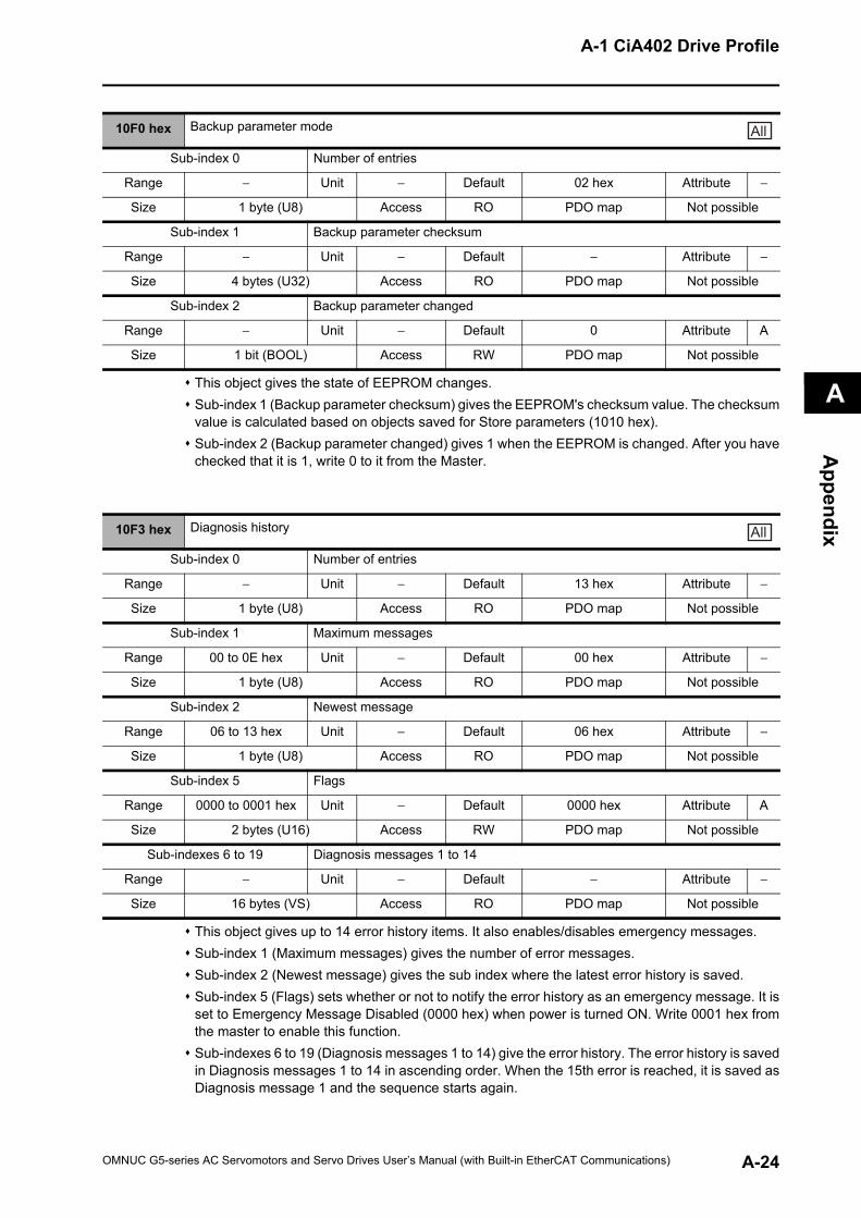
A-1 CiA402 Drive Profile
A
Appendix
This object gives the state of EEPROM changes.Sub-index 1 (Backup parameter checksum) gives the EEPROM's checksum value. The checksumvalue is calculated based on objects saved for Store parameters (1010 hex).Sub-index 2 (Backup parameter changed) gives 1 when the EEPROM is changed. After you havechecked that it is 1, write 0 to it from the Master.
This object gives up to 14 error history items. It also enables/disables emergency messages.Sub-index 1 (Maximum messages) gives the number of error messages.Sub-index 2 (Newest message) gives the sub index where the latest error history is saved.Sub-index 5 (Flags) sets whether or not to notify the error history as an emergency message. It isset to Emergency Message Disabled (0000 hex) when power is turned ON. Write 0001 hex fromthe master to enable this function.Sub-indexes 6 to 19 (Diagnosis messages 1 to 14) give the error history. The error history is savedin Diagnosis messages 1 to 14 in ascending order. When the 15th error is reached, it is saved asDiagnosis message 1 and the sequence starts again.
10F0 hex Backup parameter mode
Sub-index 0 Number of entries
Range − Unit − Default 02 hex Attribute −
Size 1 byte (U8) Access RO PDO map Not possible
Sub-index 1 Backup parameter checksum
Range − Unit − Default − Attribute −
Size 4 bytes (U32) Access RO PDO map Not possible
Sub-index 2 Backup parameter changed
Range − Unit − Default 0 Attribute A
Size 1 bit (BOOL) Access RW PDO map Not possible
All
10F3 hex Diagnosis history
Sub-index 0 Number of entries
Range − Unit − Default 13 hex Attribute −
Size 1 byte (U8) Access RO PDO map Not possible
Sub-index 1 Maximum messages
Range 00 to 0E hex Unit − Default 00 hex Attribute −
Size 1 byte (U8) Access RO PDO map Not possible
Sub-index 2 Newest message
Range 06 to 13 hex Unit − Default 06 hex Attribute −
Size 1 byte (U8) Access RO PDO map Not possible
Sub-index 5 Flags
Range 0000 to 0001 hex Unit − Default 0000 hex Attribute A
Size 2 bytes (U16) Access RW PDO map Not possible
Sub-indexes 6 to 19 Diagnosis messages 1 to 14
Range − Unit − Default − Attribute −
Size 16 bytes (VS) Access RO PDO map Not possible
All
A-24OMNUC G5-series AC Servomotors and Servo Drives User’s Manual (with Built-in EtherCAT Communications)
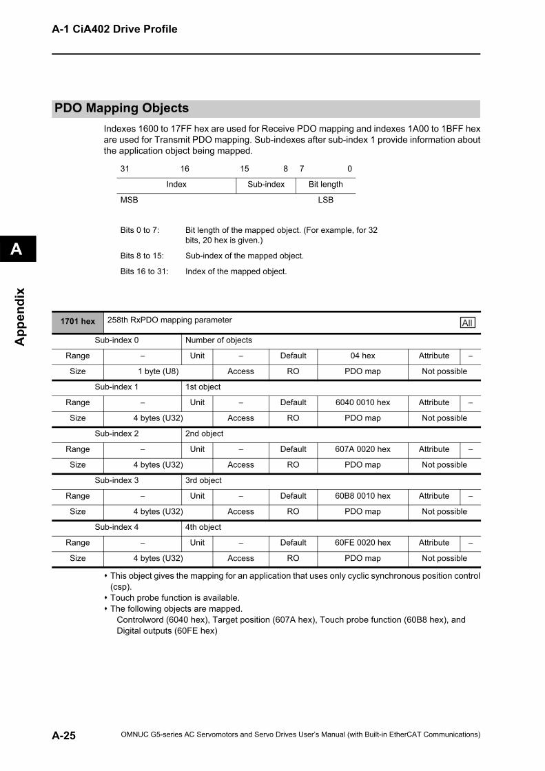
A-1 CiA402 Drive Profile
A
App
endi
x
PDO Mapping ObjectsIndexes 1600 to 17FF hex are used for Receive PDO mapping and indexes 1A00 to 1BFF hexare used for Transmit PDO mapping. Sub-indexes after sub-index 1 provide information aboutthe application object being mapped.
This object gives the mapping for an application that uses only cyclic synchronous position control(csp).Touch probe function is available.The following objects are mapped.
Controlword (6040 hex), Target position (607A hex), Touch probe function (60B8 hex), and Digital outputs (60FE hex)
31 16 15 8 7 0
Index Sub-index Bit length
MSB LSB
Bits 0 to 7: Bit length of the mapped object. (For example, for 32 bits, 20 hex is given.)
Bits 8 to 15: Sub-index of the mapped object.
Bits 16 to 31: Index of the mapped object.
1701 hex 258th RxPDO mapping parameter
Sub-index 0 Number of objects
Range − Unit − Default 04 hex Attribute −
Size 1 byte (U8) Access RO PDO map Not possible
Sub-index 1 1st object
Range − Unit − Default 6040 0010 hex Attribute −
Size 4 bytes (U32) Access RO PDO map Not possible
Sub-index 2 2nd object
Range − Unit − Default 607A 0020 hex Attribute −
Size 4 bytes (U32) Access RO PDO map Not possible
Sub-index 3 3rd object
Range − Unit − Default 60B8 0010 hex Attribute −
Size 4 bytes (U32) Access RO PDO map Not possible
Sub-index 4 4th object
Range − Unit − Default 60FE 0020 hex Attribute −
Size 4 bytes (U32) Access RO PDO map Not possible
All
A-25 OMNUC G5-series AC Servomotors and Servo Drives User’s Manual (with Built-in EtherCAT Communications)
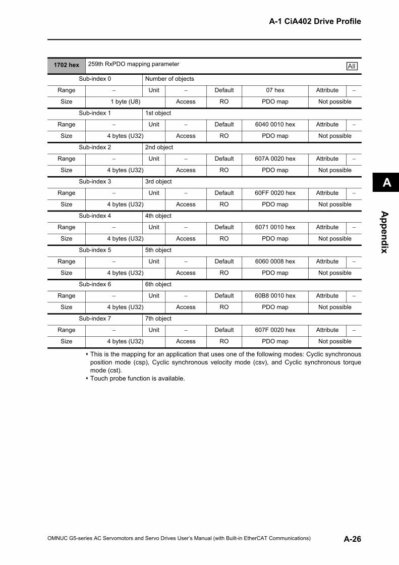
A-1 CiA402 Drive Profile
A
Appendix
This is the mapping for an application that uses one of the following modes: Cyclic synchronousposition mode (csp), Cyclic synchronous velocity mode (csv), and Cyclic synchronous torquemode (cst).Touch probe function is available.
1702 hex 259th RxPDO mapping parameter
Sub-index 0 Number of objects
Range − Unit − Default 07 hex Attribute −
Size 1 byte (U8) Access RO PDO map Not possible
Sub-index 1 1st object
Range − Unit − Default 6040 0010 hex Attribute −
Size 4 bytes (U32) Access RO PDO map Not possible
Sub-index 2 2nd object
Range − Unit − Default 607A 0020 hex Attribute −
Size 4 bytes (U32) Access RO PDO map Not possible
Sub-index 3 3rd object
Range − Unit − Default 60FF 0020 hex Attribute −
Size 4 bytes (U32) Access RO PDO map Not possible
Sub-index 4 4th object
Range − Unit − Default 6071 0010 hex Attribute −
Size 4 bytes (U32) Access RO PDO map Not possible
Sub-index 5 5th object
Range − Unit − Default 6060 0008 hex Attribute −
Size 4 bytes (U32) Access RO PDO map Not possible
Sub-index 6 6th object
Range − Unit − Default 60B8 0010 hex Attribute −
Size 4 bytes (U32) Access RO PDO map Not possible
Sub-index 7 7th object
Range − Unit − Default 607F 0020 hex Attribute −
Size 4 bytes (U32) Access RO PDO map Not possible
All
A-26OMNUC G5-series AC Servomotors and Servo Drives User’s Manual (with Built-in EtherCAT Communications)
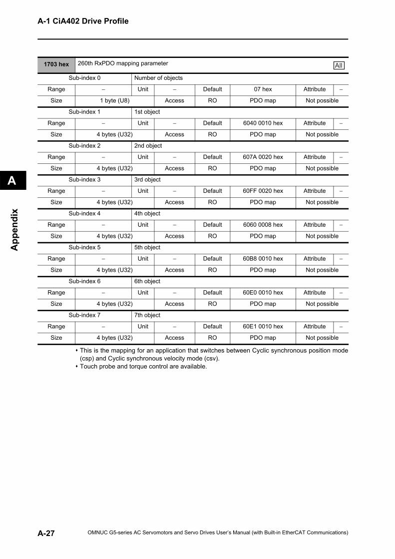
A-1 CiA402 Drive Profile
A
App
endi
x
This is the mapping for an application that switches between Cyclic synchronous position mode(csp) and Cyclic synchronous velocity mode (csv).Touch probe and torque control are available.
1703 hex 260th RxPDO mapping parameter
Sub-index 0 Number of objects
Range − Unit − Default 07 hex Attribute −
Size 1 byte (U8) Access RO PDO map Not possible
Sub-index 1 1st object
Range − Unit − Default 6040 0010 hex Attribute −
Size 4 bytes (U32) Access RO PDO map Not possible
Sub-index 2 2nd object
Range − Unit − Default 607A 0020 hex Attribute −
Size 4 bytes (U32) Access RO PDO map Not possible
Sub-index 3 3rd object
Range − Unit − Default 60FF 0020 hex Attribute −
Size 4 bytes (U32) Access RO PDO map Not possible
Sub-index 4 4th object
Range − Unit − Default 6060 0008 hex Attribute −
Size 4 bytes (U32) Access RO PDO map Not possible
Sub-index 5 5th object
Range − Unit − Default 60B8 0010 hex Attribute −
Size 4 bytes (U32) Access RO PDO map Not possible
Sub-index 6 6th object
Range − Unit − Default 60E0 0010 hex Attribute −
Size 4 bytes (U32) Access RO PDO map Not possible
Sub-index 7 7th object
Range − Unit − Default 60E1 0010 hex Attribute −
Size 4 bytes (U32) Access RO PDO map Not possible
All
A-27 OMNUC G5-series AC Servomotors and Servo Drives User’s Manual (with Built-in EtherCAT Communications)
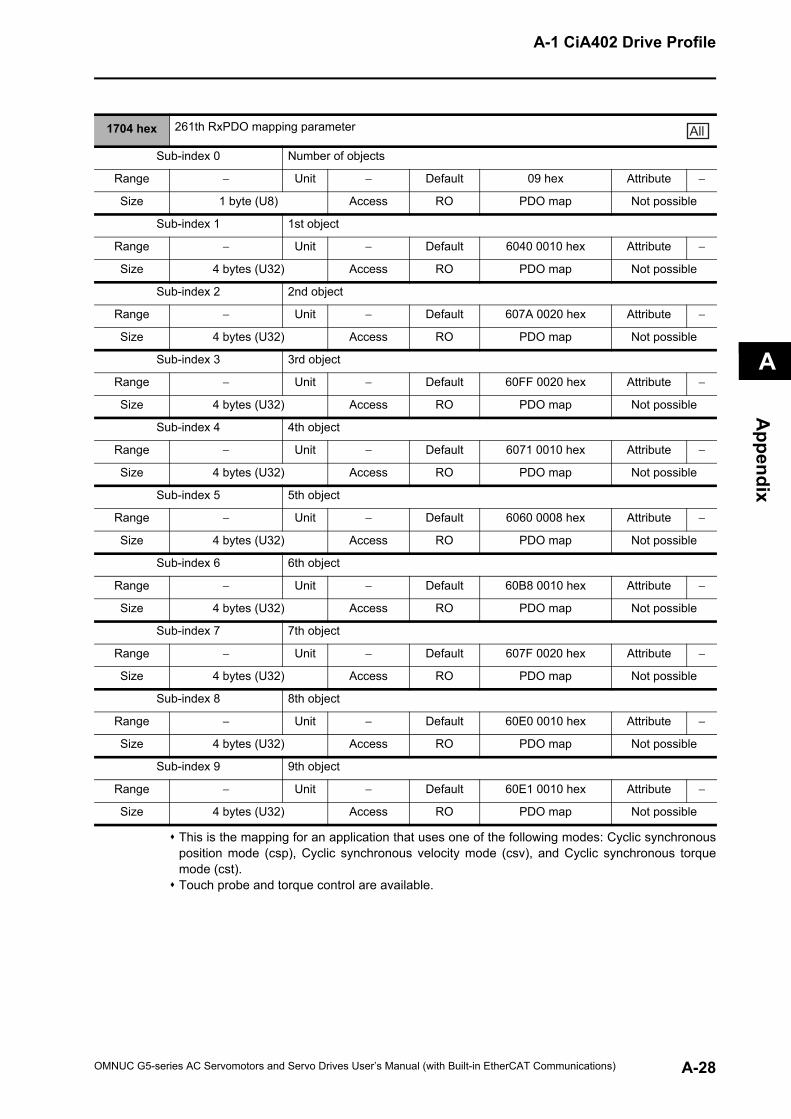
A-1 CiA402 Drive Profile
A
Appendix
This is the mapping for an application that uses one of the following modes: Cyclic synchronousposition mode (csp), Cyclic synchronous velocity mode (csv), and Cyclic synchronous torquemode (cst).Touch probe and torque control are available.
1704 hex 261th RxPDO mapping parameter
Sub-index 0 Number of objects
Range − Unit − Default 09 hex Attribute −
Size 1 byte (U8) Access RO PDO map Not possible
Sub-index 1 1st object
Range − Unit − Default 6040 0010 hex Attribute −
Size 4 bytes (U32) Access RO PDO map Not possible
Sub-index 2 2nd object
Range − Unit − Default 607A 0020 hex Attribute −
Size 4 bytes (U32) Access RO PDO map Not possible
Sub-index 3 3rd object
Range − Unit − Default 60FF 0020 hex Attribute −
Size 4 bytes (U32) Access RO PDO map Not possible
Sub-index 4 4th object
Range − Unit − Default 6071 0010 hex Attribute −
Size 4 bytes (U32) Access RO PDO map Not possible
Sub-index 5 5th object
Range − Unit − Default 6060 0008 hex Attribute −
Size 4 bytes (U32) Access RO PDO map Not possible
Sub-index 6 6th object
Range − Unit − Default 60B8 0010 hex Attribute −
Size 4 bytes (U32) Access RO PDO map Not possible
Sub-index 7 7th object
Range − Unit − Default 607F 0020 hex Attribute −
Size 4 bytes (U32) Access RO PDO map Not possible
Sub-index 8 8th object
Range − Unit − Default 60E0 0010 hex Attribute −
Size 4 bytes (U32) Access RO PDO map Not possible
Sub-index 9 9th object
Range − Unit − Default 60E1 0010 hex Attribute −
Size 4 bytes (U32) Access RO PDO map Not possible
All
A-28OMNUC G5-series AC Servomotors and Servo Drives User’s Manual (with Built-in EtherCAT Communications)

A-1 CiA402 Drive Profile
A
App
endi
x
This is the mapping for an application that switches between Cyclic synchronous position mode(csp) and Cyclic synchronous velocity mode (csv).Touch probe and torque control are available.The torque feed-forward amount can be specified using the Torque offset (60B2 hex).
1705 hex 262th RxPDO mapping parameter
Sub-index 0 Number of objects
Range − Unit − Default 08 hex Attribute −
Size 1 byte (U8) Access RO PDO map Not possible
Sub-index 1 1st object
Range − Unit − Default 6040 0010 hex Attribute −
Size 4 bytes (U32) Access RO PDO map Not possible
Sub-index 2 2nd object
Range − Unit − Default 607A 0020 hex Attribute −
Size 4 bytes (U32) Access RO PDO map Not possible
Sub-index 3 3rd object
Range − Unit − Default 60FF 0020 hex Attribute −
Size 4 bytes (U32) Access RO PDO map Not possible
Sub-index 4 4th object
Range − Unit − Default 6060 0008 hex Attribute −
Size 4 bytes (U32) Access RO PDO map Not possible
Sub-index 5 5th object
Range − Unit − Default 60B8 0010 hex Attribute −
Size 4 bytes (U32) Access RO PDO map Not possible
Sub-index 6 6th object
Range − Unit − Default 60E0 0010 hex Attribute −
Size 4 bytes (U32) Access RO PDO map Not possible
Sub-index 7 7th object
Range − Unit − Default 60E1 0010 hex Attribute −
Size 4 bytes (U32) Access RO PDO map Not possible
Sub-index 8 8th object
Range − Unit − Default 60B2 0010 hex Attribute −
Size 4 bytes (U32) Access RO PDO map Not possible
All
A-29 OMNUC G5-series AC Servomotors and Servo Drives User’s Manual (with Built-in EtherCAT Communications)
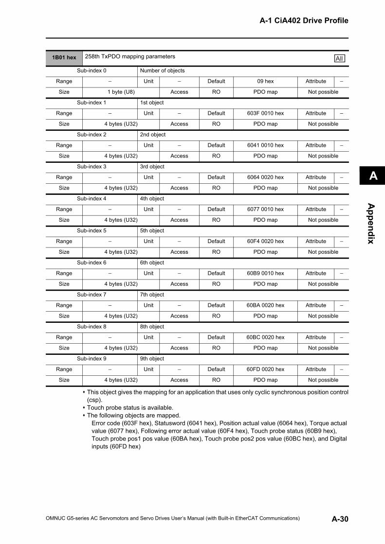
A-1 CiA402 Drive Profile
A
Appendix
This object gives the mapping for an application that uses only cyclic synchronous position control(csp).Touch probe status is available.The following objects are mapped.
Error code (603F hex), Statusword (6041 hex), Position actual value (6064 hex), Torque actual value (6077 hex), Following error actual value (60F4 hex), Touch probe status (60B9 hex), Touch probe pos1 pos value (60BA hex), Touch probe pos2 pos value (60BC hex), and Digital inputs (60FD hex)
1B01 hex 258th TxPDO mapping parameters
Sub-index 0 Number of objects
Range − Unit − Default 09 hex Attribute −
Size 1 byte (U8) Access RO PDO map Not possible
Sub-index 1 1st object
Range − Unit − Default 603F 0010 hex Attribute −
Size 4 bytes (U32) Access RO PDO map Not possible
Sub-index 2 2nd object
Range − Unit − Default 6041 0010 hex Attribute −
Size 4 bytes (U32) Access RO PDO map Not possible
Sub-index 3 3rd object
Range − Unit − Default 6064 0020 hex Attribute −
Size 4 bytes (U32) Access RO PDO map Not possible
Sub-index 4 4th object
Range − Unit − Default 6077 0010 hex Attribute −
Size 4 bytes (U32) Access RO PDO map Not possible
Sub-index 5 5th object
Range − Unit − Default 60F4 0020 hex Attribute −
Size 4 bytes (U32) Access RO PDO map Not possible
Sub-index 6 6th object
Range − Unit − Default 60B9 0010 hex Attribute −
Size 4 bytes (U32) Access RO PDO map Not possible
Sub-index 7 7th object
Range − Unit − Default 60BA 0020 hex Attribute −
Size 4 bytes (U32) Access RO PDO map Not possible
Sub-index 8 8th object
Range − Unit − Default 60BC 0020 hex Attribute −
Size 4 bytes (U32) Access RO PDO map Not possible
Sub-index 9 9th object
Range − Unit − Default 60FD 0020 hex Attribute −
Size 4 bytes (U32) Access RO PDO map Not possible
All
A-30OMNUC G5-series AC Servomotors and Servo Drives User’s Manual (with Built-in EtherCAT Communications)
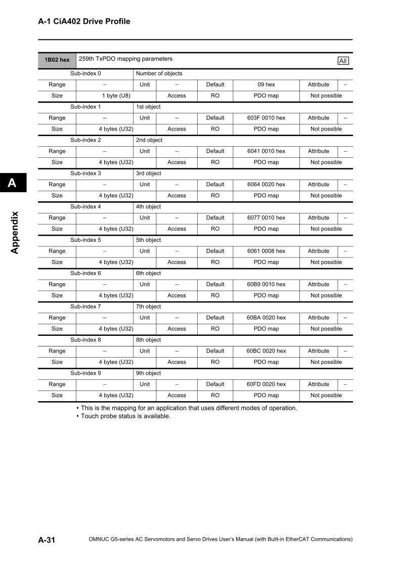
A-1 CiA402 Drive Profile
A
App
endi
x
This is the mapping for an application that uses different modes of operation.Touch probe status is available.
1B02 hex 259th TxPDO mapping parameters
Sub-index 0 Number of objects
Range − Unit − Default 09 hex Attribute −
Size 1 byte (U8) Access RO PDO map Not possible
Sub-index 1 1st object
Range − Unit − Default 603F 0010 hex Attribute −
Size 4 bytes (U32) Access RO PDO map Not possible
Sub-index 2 2nd object
Range − Unit − Default 6041 0010 hex Attribute −
Size 4 bytes (U32) Access RO PDO map Not possible
Sub-index 3 3rd object
Range − Unit − Default 6064 0020 hex Attribute −
Size 4 bytes (U32) Access RO PDO map Not possible
Sub-index 4 4th object
Range − Unit − Default 6077 0010 hex Attribute −
Size 4 bytes (U32) Access RO PDO map Not possible
Sub-index 5 5th object
Range − Unit − Default 6061 0008 hex Attribute −
Size 4 bytes (U32) Access RO PDO map Not possible
Sub-index 6 6th object
Range − Unit − Default 60B9 0010 hex Attribute −
Size 4 bytes (U32) Access RO PDO map Not possible
Sub-index 7 7th object
Range − Unit − Default 60BA 0020 hex Attribute −
Size 4 bytes (U32) Access RO PDO map Not possible
Sub-index 8 8th object
Range − Unit − Default 60BC 0020 hex Attribute −
Size 4 bytes (U32) Access RO PDO map Not possible
Sub-index 9 9th object
Range − Unit − Default 60FD 0020 hex Attribute −
Size 4 bytes (U32) Access RO PDO map Not possible
All
A-31 OMNUC G5-series AC Servomotors and Servo Drives User’s Manual (with Built-in EtherCAT Communications)
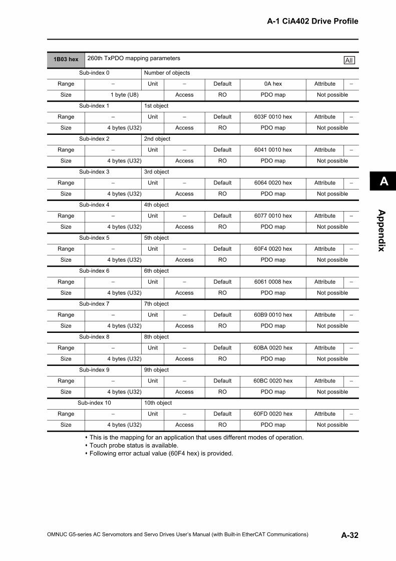
A-1 CiA402 Drive Profile
A
Appendix
This is the mapping for an application that uses different modes of operation.Touch probe status is available.Following error actual value (60F4 hex) is provided.
1B03 hex 260th TxPDO mapping parameters
Sub-index 0 Number of objects
Range − Unit − Default 0A hex Attribute −
Size 1 byte (U8) Access RO PDO map Not possible
Sub-index 1 1st object
Range − Unit − Default 603F 0010 hex Attribute −
Size 4 bytes (U32) Access RO PDO map Not possible
Sub-index 2 2nd object
Range − Unit − Default 6041 0010 hex Attribute −
Size 4 bytes (U32) Access RO PDO map Not possible
Sub-index 3 3rd object
Range − Unit − Default 6064 0020 hex Attribute −
Size 4 bytes (U32) Access RO PDO map Not possible
Sub-index 4 4th object
Range − Unit − Default 6077 0010 hex Attribute −
Size 4 bytes (U32) Access RO PDO map Not possible
Sub-index 5 5th object
Range − Unit − Default 60F4 0020 hex Attribute −
Size 4 bytes (U32) Access RO PDO map Not possible
Sub-index 6 6th object
Range − Unit − Default 6061 0008 hex Attribute −
Size 4 bytes (U32) Access RO PDO map Not possible
Sub-index 7 7th object
Range − Unit − Default 60B9 0010 hex Attribute −
Size 4 bytes (U32) Access RO PDO map Not possible
Sub-index 8 8th object
Range − Unit − Default 60BA 0020 hex Attribute −
Size 4 bytes (U32) Access RO PDO map Not possible
Sub-index 9 9th object
Range − Unit − Default 60BC 0020 hex Attribute −
Size 4 bytes (U32) Access RO PDO map Not possible
Sub-index 10 10th object
Range − Unit − Default 60FD 0020 hex Attribute −
Size 4 bytes (U32) Access RO PDO map Not possible
All
A-32OMNUC G5-series AC Servomotors and Servo Drives User’s Manual (with Built-in EtherCAT Communications)
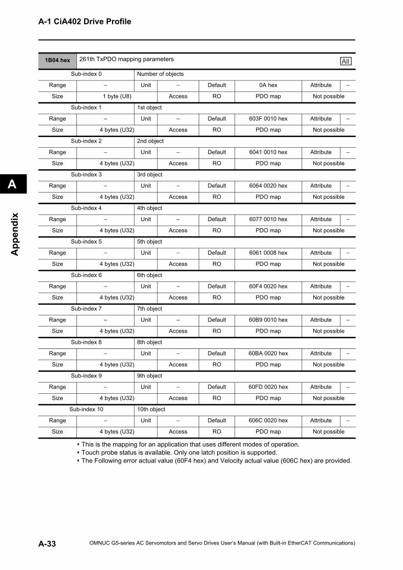
A-1 CiA402 Drive Profile
A
App
endi
x
This is the mapping for an application that uses different modes of operation.Touch probe status is available. Only one latch position is supported.The Following error actual value (60F4 hex) and Velocity actual value (606C hex) are provided.
1B04 hex 261th TxPDO mapping parameters
Sub-index 0 Number of objects
Range − Unit − Default 0A hex Attribute −
Size 1 byte (U8) Access RO PDO map Not possible
Sub-index 1 1st object
Range − Unit − Default 603F 0010 hex Attribute −
Size 4 bytes (U32) Access RO PDO map Not possible
Sub-index 2 2nd object
Range − Unit − Default 6041 0010 hex Attribute −
Size 4 bytes (U32) Access RO PDO map Not possible
Sub-index 3 3rd object
Range − Unit − Default 6064 0020 hex Attribute −
Size 4 bytes (U32) Access RO PDO map Not possible
Sub-index 4 4th object
Range − Unit − Default 6077 0010 hex Attribute −
Size 4 bytes (U32) Access RO PDO map Not possible
Sub-index 5 5th object
Range − Unit − Default 6061 0008 hex Attribute −
Size 4 bytes (U32) Access RO PDO map Not possible
Sub-index 6 6th object
Range − Unit − Default 60F4 0020 hex Attribute −
Size 4 bytes (U32) Access RO PDO map Not possible
Sub-index 7 7th object
Range − Unit − Default 60B9 0010 hex Attribute −
Size 4 bytes (U32) Access RO PDO map Not possible
Sub-index 8 8th object
Range − Unit − Default 60BA 0020 hex Attribute −
Size 4 bytes (U32) Access RO PDO map Not possible
Sub-index 9 9th object
Range − Unit − Default 60FD 0020 hex Attribute −
Size 4 bytes (U32) Access RO PDO map Not possible
Sub-index 10 10th object
Range − Unit − Default 606C 0020 hex Attribute −
Size 4 bytes (U32) Access RO PDO map Not possible
All
A-33 OMNUC G5-series AC Servomotors and Servo Drives User’s Manual (with Built-in EtherCAT Communications)
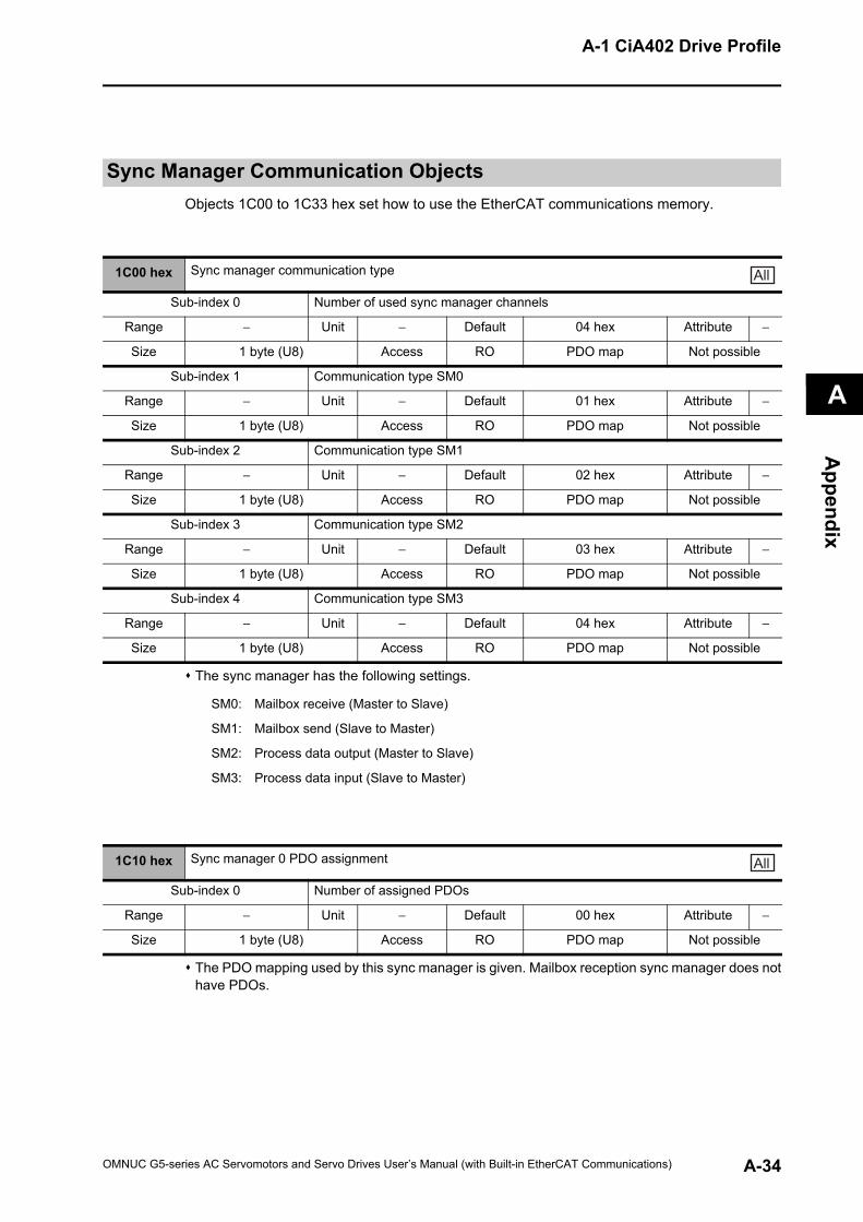
A-1 CiA402 Drive Profile
A
Appendix
Sync Manager Communication ObjectsObjects 1C00 to 1C33 hex set how to use the EtherCAT communications memory.
The sync manager has the following settings.
The PDO mapping used by this sync manager is given. Mailbox reception sync manager does nothave PDOs.
1C00 hex Sync manager communication type
Sub-index 0 Number of used sync manager channels
Range − Unit − Default 04 hex Attribute −
Size 1 byte (U8) Access RO PDO map Not possible
Sub-index 1 Communication type SM0
Range − Unit − Default 01 hex Attribute −
Size 1 byte (U8) Access RO PDO map Not possible
Sub-index 2 Communication type SM1
Range − Unit − Default 02 hex Attribute −
Size 1 byte (U8) Access RO PDO map Not possible
Sub-index 3 Communication type SM2
Range − Unit − Default 03 hex Attribute −
Size 1 byte (U8) Access RO PDO map Not possible
Sub-index 4 Communication type SM3
Range − Unit − Default 04 hex Attribute −
Size 1 byte (U8) Access RO PDO map Not possible
All
SM0: Mailbox receive (Master to Slave)
SM1: Mailbox send (Slave to Master)
SM2: Process data output (Master to Slave)
SM3: Process data input (Slave to Master)
1C10 hex Sync manager 0 PDO assignment
Sub-index 0 Number of assigned PDOs
Range − Unit − Default 00 hex Attribute −
Size 1 byte (U8) Access RO PDO map Not possible
All
A-34OMNUC G5-series AC Servomotors and Servo Drives User’s Manual (with Built-in EtherCAT Communications)
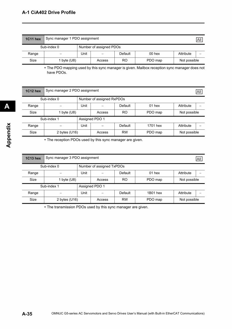
A-1 CiA402 Drive Profile
A
App
endi
x
The PDO mapping used by this sync manager is given. Mailbox reception sync manager does nothave PDOs.
The reception PDOs used by this sync manager are given.
The transmission PDOs used by this sync manager are given.
1C11 hex Sync manager 1 PDO assignment
Sub-index 0 Number of assigned PDOs
Range − Unit − Default 00 hex Attribute −
Size 1 byte (U8) Access RO PDO map Not possible
All
1C12 hex Sync manager 2 PDO assignment
Sub-index 0 Number of assigned RxPDOs
Range − Unit − Default 01 hex Attribute −
Size 1 byte (U8) Access RO PDO map Not possible
Sub-index 1 Assigned PDO 1
Range − Unit − Default 1701 hex Attribute −
Size 2 bytes (U16) Access RW PDO map Not possible
All
1C13 hex Sync manager 3 PDO assignment
Sub-index 0 Number of assigned TxPDOs
Range − Unit − Default 01 hex Attribute −
Size 1 byte (U8) Access RO PDO map Not possible
Sub-index 1 Assigned PDO 1
Range − Unit − Default 1B01 hex Attribute −
Size 2 bytes (U16) Access RW PDO map Not possible
All
A-35 OMNUC G5-series AC Servomotors and Servo Drives User’s Manual (with Built-in EtherCAT Communications)
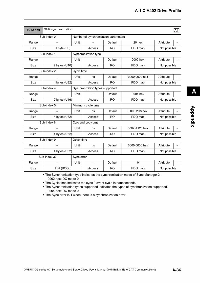
A-1 CiA402 Drive Profile
A
Appendix
The Synchronization type indicates the synchronization mode of Sync Manager 2.0002 hex: DC mode 0
The Cycle time indicates the sync 0 event cycle in nanoseconds.The Synchronization types supported indicates the types of synchronization supported.
0004 hex: DC mode 0The Sync error is 1 when there is a synchronization error.
1C32 hex SM2 synchronization
Sub-index 0 Number of synchronization parameters
Range − Unit − Default 20 hex Attribute −
Size 1 byte (U8) Access RO PDO map Not possible
Sub-index 1 Synchronization type
Range − Unit − Default 0002 hex Attribute −
Size 2 bytes (U16) Access RO PDO map Not possible
Sub-index 2 Cycle time
Range − Unit ns Default 0000 0000 hex Attribute −
Size 4 bytes (U32) Access RO PDO map Not possible
Sub-index 4 Synchronization types supported
Range − Unit − Default 0004 hex Attribute −
Size 2 bytes (U16) Access RO PDO map Not possible
Sub-index 5 Minimum cycle time
Range − Unit ns Default 0003 2C8 hex Attribute −
Size 4 bytes (U32) Access RO PDO map Not possible
Sub-index 6 Calc and copy time
Range − Unit ns Default 0007 A120 hex Attribute −
Size 4 bytes (U32) Access RO PDO map Not possible
Sub-index 9 Delay time
Range − Unit ns Default 0000 0000 hex Attribute −
Size 4 bytes (U32) Access RO PDO map Not possible
Sub-index 32 Sync error
Range − Unit − Default 0 Attribute −
Size 1 bit (BOOL) Access RO PDO map Not possible
All
A-36OMNUC G5-series AC Servomotors and Servo Drives User’s Manual (with Built-in EtherCAT Communications)
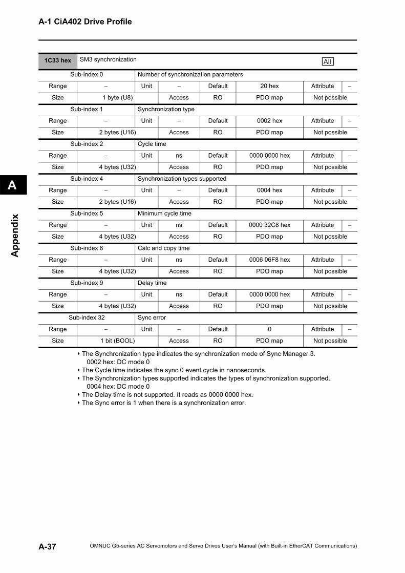
A-1 CiA402 Drive Profile
A
App
endi
x
The Synchronization type indicates the synchronization mode of Sync Manager 3.0002 hex: DC mode 0
The Cycle time indicates the sync 0 event cycle in nanoseconds.The Synchronization types supported indicates the types of synchronization supported.
0004 hex: DC mode 0The Delay time is not supported. It reads as 0000 0000 hex.The Sync error is 1 when there is a synchronization error.
1C33 hex SM3 synchronization
Sub-index 0 Number of synchronization parameters
Range − Unit − Default 20 hex Attribute −
Size 1 byte (U8) Access RO PDO map Not possible
Sub-index 1 Synchronization type
Range − Unit − Default 0002 hex Attribute −
Size 2 bytes (U16) Access RO PDO map Not possible
Sub-index 2 Cycle time
Range − Unit ns Default 0000 0000 hex Attribute −
Size 4 bytes (U32) Access RO PDO map Not possible
Sub-index 4 Synchronization types supported
Range − Unit − Default 0004 hex Attribute −
Size 2 bytes (U16) Access RO PDO map Not possible
Sub-index 5 Minimum cycle time
Range − Unit ns Default 0000 32C8 hex Attribute −
Size 4 bytes (U32) Access RO PDO map Not possible
Sub-index 6 Calc and copy time
Range − Unit ns Default 0006 06F8 hex Attribute −
Size 4 bytes (U32) Access RO PDO map Not possible
Sub-index 9 Delay time
Range − Unit ns Default 0000 0000 hex Attribute −
Size 4 bytes (U32) Access RO PDO map Not possible
Sub-index 32 Sync error
Range − Unit − Default 0 Attribute −
Size 1 bit (BOOL) Access RO PDO map Not possible
All
A-37 OMNUC G5-series AC Servomotors and Servo Drives User’s Manual (with Built-in EtherCAT Communications)
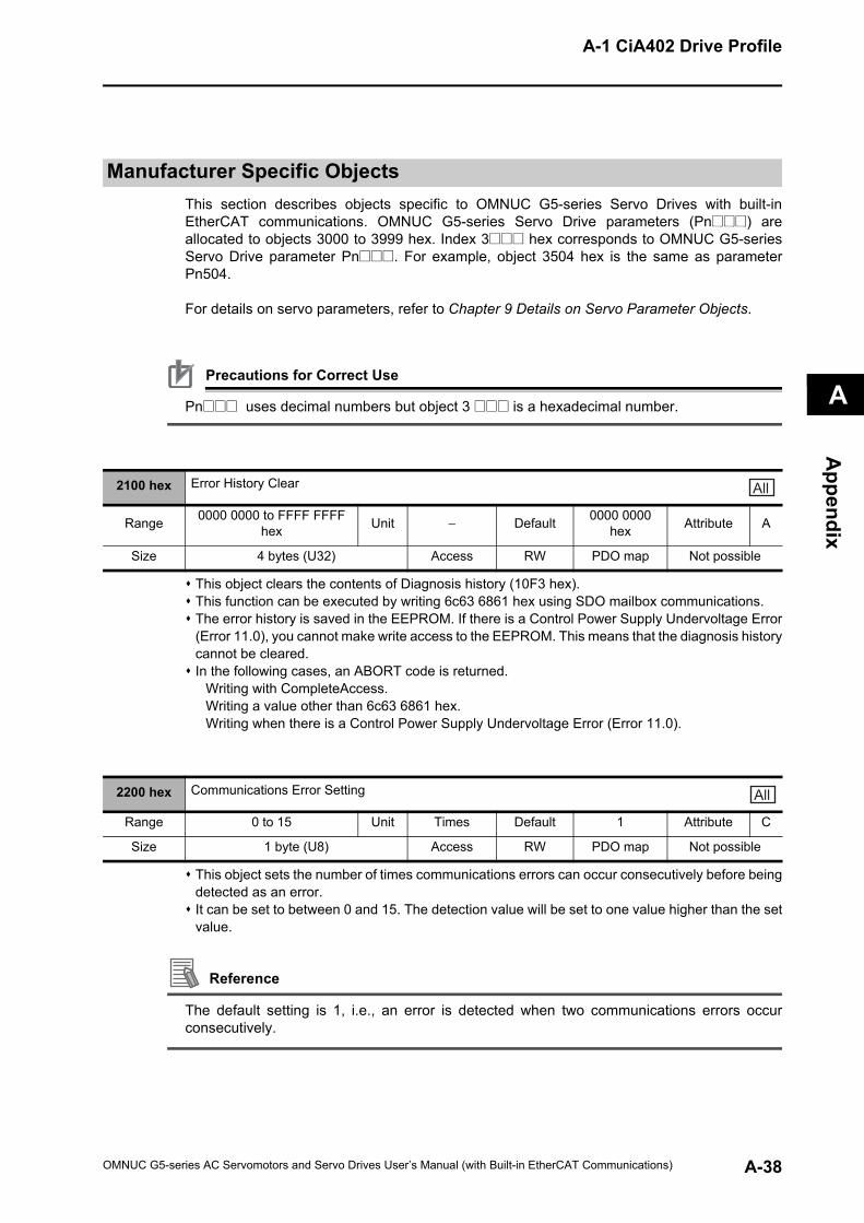
A-1 CiA402 Drive Profile
A
Appendix
Manufacturer Specific ObjectsThis section describes objects specific to OMNUC G5-series Servo Drives with built-inEtherCAT communications. OMNUC G5-series Servo Drive parameters (Pn@@@) areallocated to objects 3000 to 3999 hex. Index 3@@@ hex corresponds to OMNUC G5-seriesServo Drive parameter Pn@@@. For example, object 3504 hex is the same as parameterPn504.
For details on servo parameters, refer to Chapter 9 Details on Servo Parameter Objects.
Precautions for Correct Use
Pn@@@ uses decimal numbers but object 3 @@@ is a hexadecimal number.
This object clears the contents of Diagnosis history (10F3 hex).This function can be executed by writing 6c63 6861 hex using SDO mailbox communications.The error history is saved in the EEPROM. If there is a Control Power Supply Undervoltage Error(Error 11.0), you cannot make write access to the EEPROM. This means that the diagnosis historycannot be cleared.In the following cases, an ABORT code is returned.
Writing with CompleteAccess.Writing a value other than 6c63 6861 hex.Writing when there is a Control Power Supply Undervoltage Error (Error 11.0).
This object sets the number of times communications errors can occur consecutively before beingdetected as an error.It can be set to between 0 and 15. The detection value will be set to one value higher than the setvalue.
Reference
The default setting is 1, i.e., an error is detected when two communications errors occurconsecutively.
2100 hex Error History Clear
Range 0000 0000 to FFFF FFFF hex Unit − Default 0000 0000
hex Attribute A
Size 4 bytes (U32) Access RW PDO map Not possible
All
2200 hex Communications Error Setting
Range 0 to 15 Unit Times Default 1 Attribute C
Size 1 byte (U8) Access RW PDO map Not possible
All
A-38OMNUC G5-series AC Servomotors and Servo Drives User’s Manual (with Built-in EtherCAT Communications)
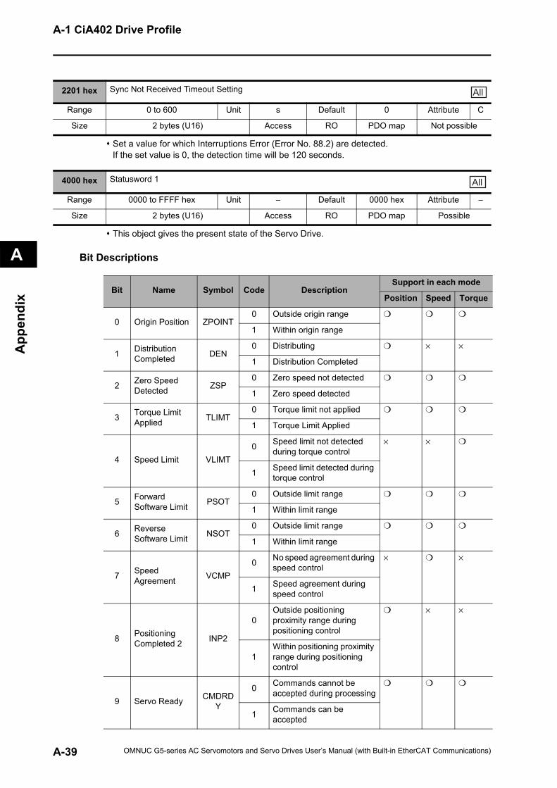
A-1 CiA402 Drive Profile
A
App
endi
x
Set a value for which Interruptions Error (Error No. 88.2) are detected.If the set value is 0, the detection time will be 120 seconds.
This object gives the present state of the Servo Drive.
Bit Descriptions
2201 hex Sync Not Received Timeout Setting
Range 0 to 600 Unit s Default 0 Attribute C
Size 2 bytes (U16) Access RO PDO map Not possible
All
4000 hex Statusword 1
Range 0000 to FFFF hex Unit − Default 0000 hex Attribute −
Size 2 bytes (U16) Access RO PDO map Possible
All
Bit Name Symbol Code DescriptionSupport in each mode
Position Speed Torque
0 Origin Position ZPOINT0 Outside origin range
1 Within origin range
1 Distribution Completed DEN
0 Distributing × ×
1 Distribution Completed
2 Zero Speed Detected ZSP
0 Zero speed not detected
1 Zero speed detected
3 Torque Limit Applied TLIMT
0 Torque limit not applied
1 Torque Limit Applied
4 Speed Limit VLIMT0 Speed limit not detected
during torque control× ×
1 Speed limit detected during torque control
5 Forward Software Limit PSOT
0 Outside limit range
1 Within limit range
6 Reverse Software Limit NSOT
0 Outside limit range
1 Within limit range
7 Speed Agreement VCMP
0 No speed agreement during speed control
× ×
1 Speed agreement during speed control
8 Positioning Completed 2 INP2
0Outside positioning proximity range during positioning control
× ×
1Within positioning proximity range during positioning control
9 Servo Ready CMDRDY
0 Commands cannot be accepted during processing
1 Commands can be accepted
A-39 OMNUC G5-series AC Servomotors and Servo Drives User’s Manual (with Built-in EtherCAT Communications)
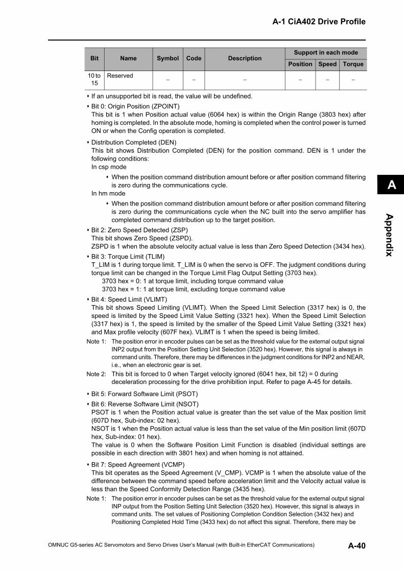
A-1 CiA402 Drive Profile
A
Appendix
If an unsupported bit is read, the value will be undefined.Bit 0: Origin Position (ZPOINT) This bit is 1 when Position actual value (6064 hex) is within the Origin Range (3803 hex) afterhoming is completed. In the absolute mode, homing is completed when the control power is turnedON or when the Config operation is completed.
Distribution Completed (DEN)This bit shows Distribution Completed (DEN) for the position command. DEN is 1 under thefollowing conditions:In csp mode
When the position command distribution amount before or after position command filteringis zero during the communications cycle.
In hm modeWhen the position command distribution amount before or after position command filteringis zero during the communications cycle when the NC built into the servo amplifier hascompleted command distribution up to the target position.
Bit 2: Zero Speed Detected (ZSP)This bit shows Zero Speed (ZSPD).ZSPD is 1 when the absolute velocity actual value is less than Zero Speed Detection (3434 hex).Bit 3: Torque Limit (TLIM)T_LIM is 1 during torque limit. T_LIM is 0 when the servo is OFF. The judgment conditions duringtorque limit can be changed in the Torque Limit Flag Output Setting (3703 hex).
3703 hex = 0: 1 at torque limit, including torque command value3703 hex = 1: 1 at torque limit, excluding torque command value
Bit 4: Speed Limit (VLIMT)This bit shows Speed Limiting (VLIMT). When the Speed Limit Selection (3317 hex) is 0, thespeed is limited by the Speed Limit Value Setting (3321 hex). When the Speed Limit Selection(3317 hex) is 1, the speed is limited by the smaller of the Speed Limit Value Setting (3321 hex)and Max profile velocity (607F hex). VLIMT is 1 when the speed is being limited.
Note 1: The position error in encoder pulses can be set as the threshold value for the external output signal INP2 output from the Position Setting Unit Selection (3520 hex). However, this signal is always in command units. Therefore, there may be differences in the judgment conditions for INP2 and NEAR, i.e., when an electronic gear is set.
Note 2: This bit is forced to 0 when Target velocity ignored (6041 hex, bit 12) = 0 during deceleration processing for the drive prohibition input. Refer to page A-45 for details.
Bit 5: Forward Software Limit (PSOT)Bit 6: Reverse Software Limit (NSOT)PSOT is 1 when the Position actual value is greater than the set value of the Max position limit(607D hex, Sub-index: 02 hex).NSOT is 1 when the Position actual value is less than the set value of the Min position limit (607Dhex, Sub-index: 01 hex).The value is 0 when the Software Position Limit Function is disabled (individual settings arepossible in each direction with 3801 hex) and when homing is not attained.
Bit 7: Speed Agreement (VCMP)This bit operates as the Speed Agreement (V_CMP). VCMP is 1 when the absolute value of thedifference between the command speed before acceleration limit and the Velocity actual value isless than the Speed Conformity Detection Range (3435 hex).
Note 1: The position error in encoder pulses can be set as the threshold value for the external output signal INP output from the Position Setting Unit Selection (3520 hex). However, this signal is always in command units. The set values of Positioning Completion Condition Selection (3432 hex) and Positioning Completed Hold Time (3433 hex) do not affect this signal. Therefore, there may be
10 to 15
Reserved − − − − − −
Bit Name Symbol Code DescriptionSupport in each mode
Position Speed Torque
A-40OMNUC G5-series AC Servomotors and Servo Drives User’s Manual (with Built-in EtherCAT Communications)
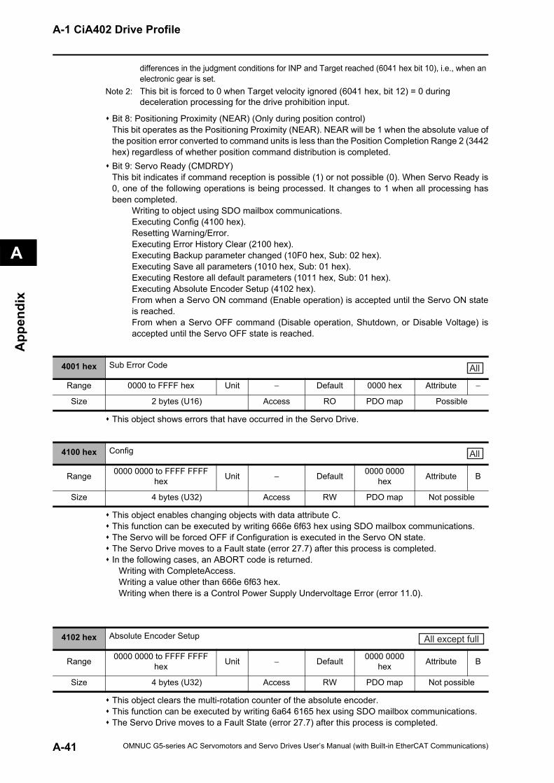
A-1 CiA402 Drive Profile
A
App
endi
x
differences in the judgment conditions for INP and Target reached (6041 hex bit 10), i.e., when an electronic gear is set.
Note 2: This bit is forced to 0 when Target velocity ignored (6041 hex, bit 12) = 0 during deceleration processing for the drive prohibition input.
Bit 8: Positioning Proximity (NEAR) (Only during position control)This bit operates as the Positioning Proximity (NEAR). NEAR will be 1 when the absolute value ofthe position error converted to command units is less than the Position Completion Range 2 (3442hex) regardless of whether position command distribution is completed.Bit 9: Servo Ready (CMDRDY)This bit indicates if command reception is possible (1) or not possible (0). When Servo Ready is0, one of the following operations is being processed. It changes to 1 when all processing hasbeen completed.
Writing to object using SDO mailbox communications.Executing Config (4100 hex).Resetting Warning/Error.Executing Error History Clear (2100 hex).Executing Backup parameter changed (10F0 hex, Sub: 02 hex).Executing Save all parameters (1010 hex, Sub: 01 hex).Executing Restore all default parameters (1011 hex, Sub: 01 hex).Executing Absolute Encoder Setup (4102 hex).From when a Servo ON command (Enable operation) is accepted until the Servo ON stateis reached.From when a Servo OFF command (Disable operation, Shutdown, or Disable Voltage) isaccepted until the Servo OFF state is reached.
This object shows errors that have occurred in the Servo Drive.
This object enables changing objects with data attribute C.This function can be executed by writing 666e 6f63 hex using SDO mailbox communications.The Servo will be forced OFF if Configuration is executed in the Servo ON state.The Servo Drive moves to a Fault state (error 27.7) after this process is completed.In the following cases, an ABORT code is returned.
Writing with CompleteAccess.Writing a value other than 666e 6f63 hex.Writing when there is a Control Power Supply Undervoltage Error (error 11.0).
This object clears the multi-rotation counter of the absolute encoder.This function can be executed by writing 6a64 6165 hex using SDO mailbox communications.The Servo Drive moves to a Fault State (error 27.7) after this process is completed.
4001 hex Sub Error Code
Range 0000 to FFFF hex Unit − Default 0000 hex Attribute −
Size 2 bytes (U16) Access RO PDO map Possible
All
4100 hex Config
Range 0000 0000 to FFFF FFFF hex Unit − Default 0000 0000
hex Attribute B
Size 4 bytes (U32) Access RW PDO map Not possible
All
4102 hex Absolute Encoder Setup
Range 0000 0000 to FFFF FFFF hex Unit − Default 0000 0000
hex Attribute B
Size 4 bytes (U32) Access RW PDO map Not possible
All except full
A-41 OMNUC G5-series AC Servomotors and Servo Drives User’s Manual (with Built-in EtherCAT Communications)
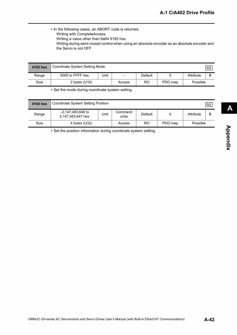
A-1 CiA402 Drive Profile
A
Appendix
In the following cases, an ABORT code is returned.Writing with CompleteAccess.Writing a value other than 6a64 6165 hex.Writing during semi-closed control when using an absolute encoder as an absolute encoder and the Servo is not OFF.
Set the mode during coordinate system setting.
Set the position information during coordinate system setting.
4103 hex Coordinate System Setting Mode
Range 0000 to FFFF hex Unit − Default 0 Attribute B
Size 2 bytes (U16) Access RO PDO map Possible
All
4104 hex Coordinate System Setting Position
Range −2,147,483,648 to 2,147,483,647 hex Unit Command
units Default 0 Attribute B
Size 4 bytes (U32) Access RO PDO map Possible
All
A-42OMNUC G5-series AC Servomotors and Servo Drives User’s Manual (with Built-in EtherCAT Communications)
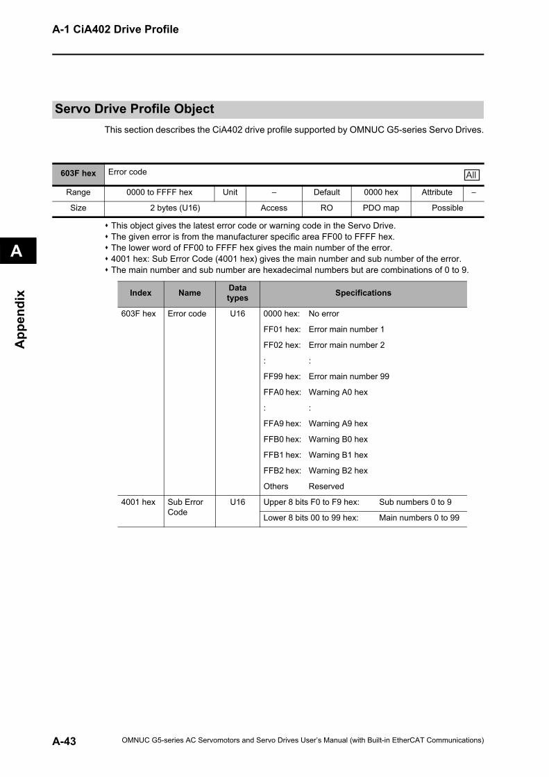
A-1 CiA402 Drive Profile
A
App
endi
x
Servo Drive Profile ObjectThis section describes the CiA402 drive profile supported by OMNUC G5-series Servo Drives.
This object gives the latest error code or warning code in the Servo Drive.The given error is from the manufacturer specific area FF00 to FFFF hex.The lower word of FF00 to FFFF hex gives the main number of the error.4001 hex: Sub Error Code (4001 hex) gives the main number and sub number of the error.The main number and sub number are hexadecimal numbers but are combinations of 0 to 9.
603F hex Error code
Range 0000 to FFFF hex Unit − Default 0000 hex Attribute −
Size 2 bytes (U16) Access RO PDO map Possible
All
Index Name Data types Specifications
603F hex Error code U16 0000 hex: No error
FF01 hex: Error main number 1
FF02 hex: Error main number 2
: :
FF99 hex: Error main number 99
FFA0 hex: Warning A0 hex
: :
FFA9 hex: Warning A9 hex
FFB0 hex: Warning B0 hex
FFB1 hex: Warning B1 hex
FFB2 hex: Warning B2 hex
Others Reserved
4001 hex Sub Error Code
U16 Upper 8 bits F0 to F9 hex: Sub numbers 0 to 9
Lower 8 bits 00 to 99 hex: Main numbers 0 to 99
A-43 OMNUC G5-series AC Servomotors and Servo Drives User’s Manual (with Built-in EtherCAT Communications)
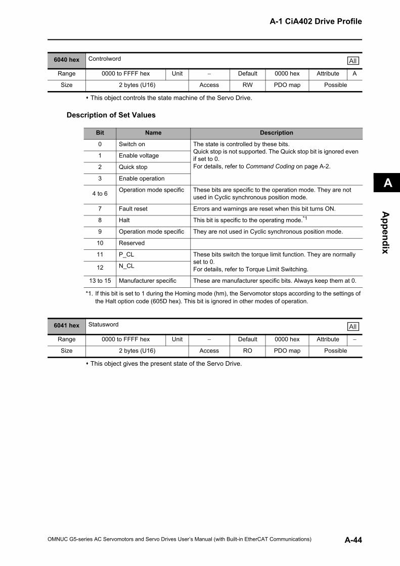
A-1 CiA402 Drive Profile
A
Appendix
This object controls the state machine of the Servo Drive.
Description of Set Values
*1. If this bit is set to 1 during the Homing mode (hm), the Servomotor stops according to the settings of the Halt option code (605D hex). This bit is ignored in other modes of operation.
This object gives the present state of the Servo Drive.
6040 hex Controlword
Range 0000 to FFFF hex Unit − Default 0000 hex Attribute A
Size 2 bytes (U16) Access RW PDO map Possible
All
Bit Name Description
0 Switch on The state is controlled by these bits.Quick stop is not supported. The Quick stop bit is ignored even if set to 0.For details, refer to Command Coding on page A-2.
1 Enable voltage
2 Quick stop
3 Enable operation
4 to 6 Operation mode specific These bits are specific to the operation mode. They are not used in Cyclic synchronous position mode.
7 Fault reset Errors and warnings are reset when this bit turns ON.
8 Halt This bit is specific to the operating mode.*1
9 Operation mode specific They are not used in Cyclic synchronous position mode.
10 Reserved
11 P_CL These bits switch the torque limit function. They are normally set to 0.For details, refer to Torque Limit Switching.12 N_CL
13 to 15 Manufacturer specific These are manufacturer specific bits. Always keep them at 0.
6041 hex Statusword
Range 0000 to FFFF hex Unit − Default 0000 hex Attribute −
Size 2 bytes (U16) Access RO PDO map Possible
All
A-44OMNUC G5-series AC Servomotors and Servo Drives User’s Manual (with Built-in EtherCAT Communications)
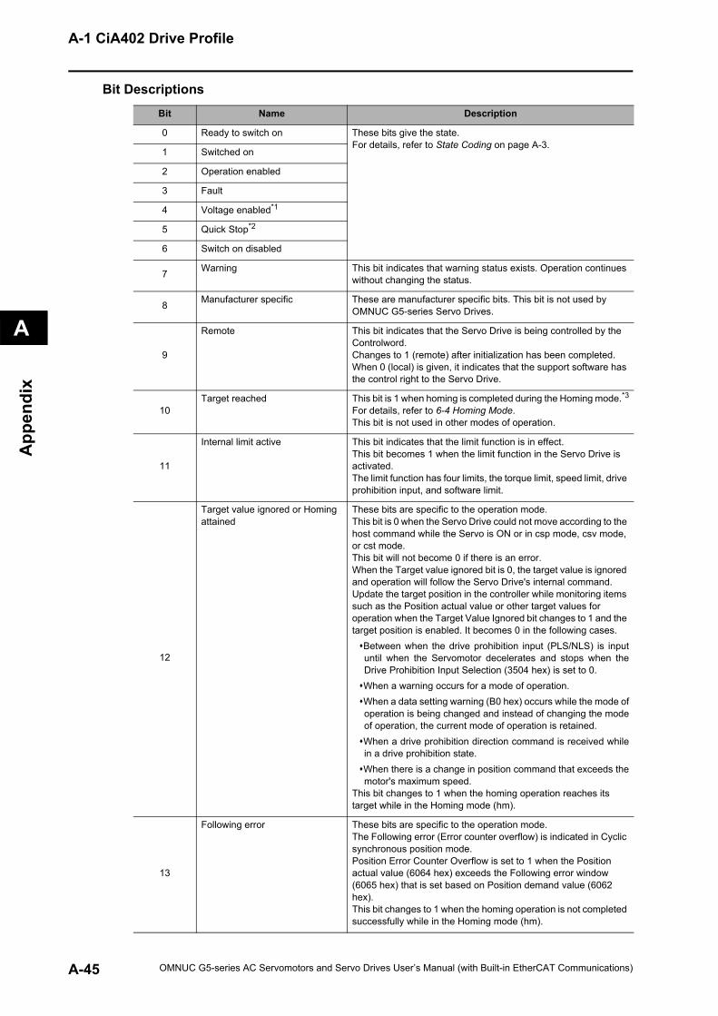
A-1 CiA402 Drive Profile
A
App
endi
x
Bit DescriptionsBit Name Description
0 Ready to switch on These bits give the state.For details, refer to State Coding on page A-3.
1 Switched on
2 Operation enabled
3 Fault
4 Voltage enabled*1
5 Quick Stop*2
6 Switch on disabled
7 Warning This bit indicates that warning status exists. Operation continues without changing the status.
8 Manufacturer specific These are manufacturer specific bits. This bit is not used by OMNUC G5-series Servo Drives.
9
Remote This bit indicates that the Servo Drive is being controlled by the Controlword.Changes to 1 (remote) after initialization has been completed.When 0 (local) is given, it indicates that the support software has the control right to the Servo Drive.
10Target reached This bit is 1 when homing is completed during the Homing mode.*3
For details, refer to 6-4 Homing Mode.This bit is not used in other modes of operation.
11
Internal limit active This bit indicates that the limit function is in effect.This bit becomes 1 when the limit function in the Servo Drive is activated.The limit function has four limits, the torque limit, speed limit, drive prohibition input, and software limit.
12
Target value ignored or Homing attained
These bits are specific to the operation mode. This bit is 0 when the Servo Drive could not move according to the host command while the Servo is ON or in csp mode, csv mode, or cst mode. This bit will not become 0 if there is an error. When the Target value ignored bit is 0, the target value is ignored and operation will follow the Servo Drive's internal command. Update the target position in the controller while monitoring items such as the Position actual value or other target values for operation when the Target Value Ignored bit changes to 1 and the target position is enabled. It becomes 0 in the following cases.
Between when the drive prohibition input (PLS/NLS) is inputuntil when the Servomotor decelerates and stops when theDrive Prohibition Input Selection (3504 hex) is set to 0.When a warning occurs for a mode of operation.When a data setting warning (B0 hex) occurs while the mode ofoperation is being changed and instead of changing the modeof operation, the current mode of operation is retained.When a drive prohibition direction command is received whilein a drive prohibition state.When there is a change in position command that exceeds themotor's maximum speed.
This bit changes to 1 when the homing operation reaches its target while in the Homing mode (hm).
13
Following error These bits are specific to the operation mode.The Following error (Error counter overflow) is indicated in Cyclic synchronous position mode.Position Error Counter Overflow is set to 1 when the Position actual value (6064 hex) exceeds the Following error window (6065 hex) that is set based on Position demand value (6062 hex).This bit changes to 1 when the homing operation is not completed successfully while in the Homing mode (hm).
A-45 OMNUC G5-series AC Servomotors and Servo Drives User’s Manual (with Built-in EtherCAT Communications)
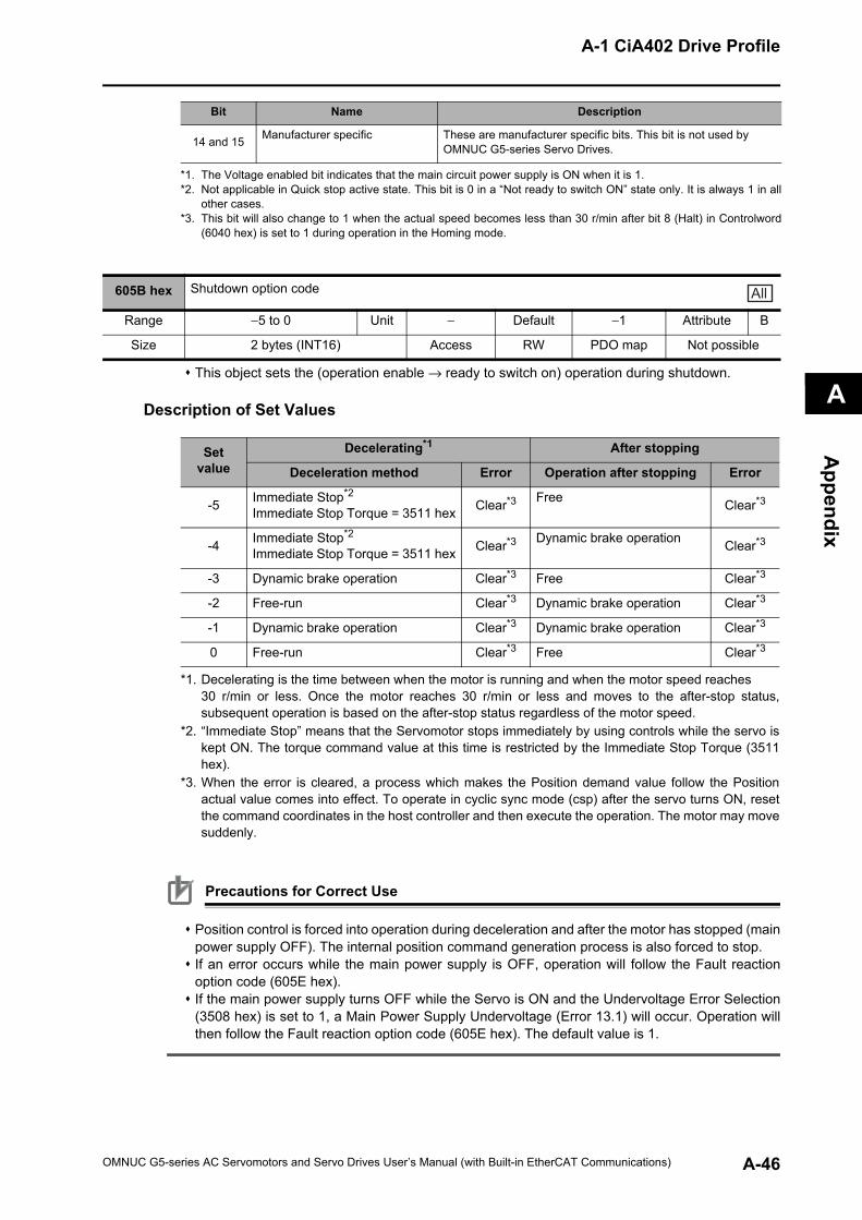
A-1 CiA402 Drive Profile
A
Appendix
This object sets the (operation enable → ready to switch on) operation during shutdown.
Description of Set Values
Precautions for Correct Use
Position control is forced into operation during deceleration and after the motor has stopped (mainpower supply OFF). The internal position command generation process is also forced to stop.If an error occurs while the main power supply is OFF, operation will follow the Fault reactionoption code (605E hex).If the main power supply turns OFF while the Servo is ON and the Undervoltage Error Selection(3508 hex) is set to 1, a Main Power Supply Undervoltage (Error 13.1) will occur. Operation willthen follow the Fault reaction option code (605E hex). The default value is 1.
14 and 15 Manufacturer specific These are manufacturer specific bits. This bit is not used by OMNUC G5-series Servo Drives.
*1. The Voltage enabled bit indicates that the main circuit power supply is ON when it is 1.*2. Not applicable in Quick stop active state. This bit is 0 in a “Not ready to switch ON” state only. It is always 1 in all
other cases.*3. This bit will also change to 1 when the actual speed becomes less than 30 r/min after bit 8 (Halt) in Controlword
(6040 hex) is set to 1 during operation in the Homing mode.
Bit Name Description
605B hex Shutdown option code
Range −5 to 0 Unit − Default −1 Attribute B
Size 2 bytes (INT16) Access RW PDO map Not possible
All
Set value
Decelerating*1
*1. Decelerating is the time between when the motor is running and when the motor speed reaches 30 r/min or less. Once the motor reaches 30 r/min or less and moves to the after-stop status,subsequent operation is based on the after-stop status regardless of the motor speed.
After stopping
Deceleration method Error Operation after stopping Error
-5 Immediate Stop*2
Immediate Stop Torque = 3511 hex
*2. “Immediate Stop” means that the Servomotor stops immediately by using controls while the servo iskept ON. The torque command value at this time is restricted by the Immediate Stop Torque (3511hex).
Clear*3 Free Clear*3
*3. When the error is cleared, a process which makes the Position demand value follow the Positionactual value comes into effect. To operate in cyclic sync mode (csp) after the servo turns ON, resetthe command coordinates in the host controller and then execute the operation. The motor may movesuddenly.
-4 Immediate Stop*2
Immediate Stop Torque = 3511 hex Clear*3 Dynamic brake operation Clear*3
-3 Dynamic brake operation Clear*3 Free Clear*3
-2 Free-run Clear*3 Dynamic brake operation Clear*3
-1 Dynamic brake operation Clear*3 Dynamic brake operation Clear*3
0 Free-run Clear*3 Free Clear*3
A-46OMNUC G5-series AC Servomotors and Servo Drives User’s Manual (with Built-in EtherCAT Communications)
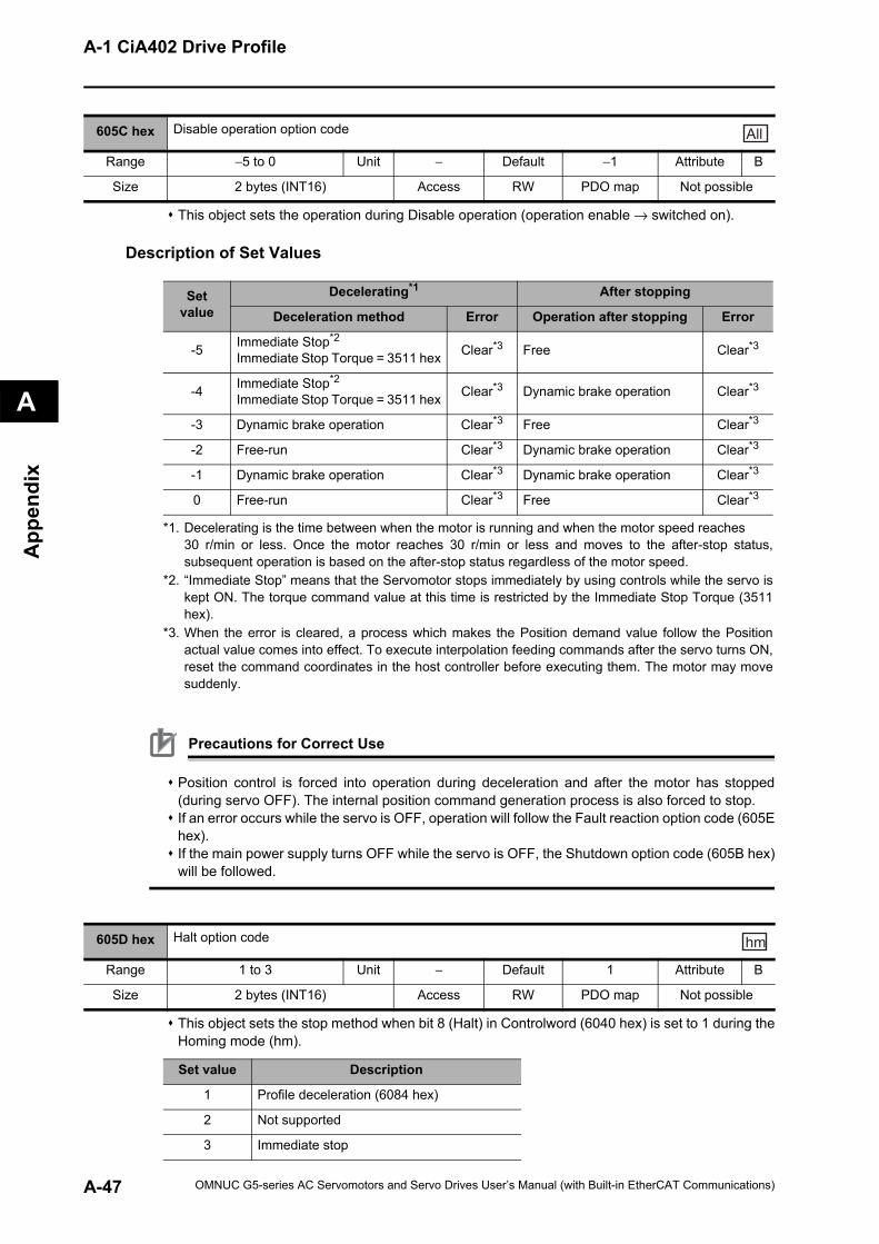
A-1 CiA402 Drive Profile
A
App
endi
x
This object sets the operation during Disable operation (operation enable → switched on).
Description of Set Values
Precautions for Correct Use
Position control is forced into operation during deceleration and after the motor has stopped(during servo OFF). The internal position command generation process is also forced to stop.If an error occurs while the servo is OFF, operation will follow the Fault reaction option code (605Ehex).If the main power supply turns OFF while the servo is OFF, the Shutdown option code (605B hex)will be followed.
This object sets the stop method when bit 8 (Halt) in Controlword (6040 hex) is set to 1 during theHoming mode (hm).
605C hex Disable operation option code
Range −5 to 0 Unit − Default −1 Attribute B
Size 2 bytes (INT16) Access RW PDO map Not possible
All
Set value
Decelerating*1
*1. Decelerating is the time between when the motor is running and when the motor speed reaches 30 r/min or less. Once the motor reaches 30 r/min or less and moves to the after-stop status,subsequent operation is based on the after-stop status regardless of the motor speed.
After stopping
Deceleration method Error Operation after stopping Error
-5 Immediate Stop*2
Immediate Stop Torque = 3511 hex
*2. “Immediate Stop” means that the Servomotor stops immediately by using controls while the servo iskept ON. The torque command value at this time is restricted by the Immediate Stop Torque (3511hex).
Clear*3 Free Clear*3
*3. When the error is cleared, a process which makes the Position demand value follow the Positionactual value comes into effect. To execute interpolation feeding commands after the servo turns ON,reset the command coordinates in the host controller before executing them. The motor may movesuddenly.
-4 Immediate Stop*2
Immediate Stop Torque = 3511 hex Clear*3 Dynamic brake operation Clear*3
-3 Dynamic brake operation Clear*3 Free Clear*3
-2 Free-run Clear*3 Dynamic brake operation Clear*3
-1 Dynamic brake operation Clear*3 Dynamic brake operation Clear*3
0 Free-run Clear*3 Free Clear*3
605D hex Halt option code
Range 1 to 3 Unit − Default 1 Attribute B
Size 2 bytes (INT16) Access RW PDO map Not possible
hm
Set value Description
1 Profile deceleration (6084 hex)
2 Not supported
3 Immediate stop
A-47 OMNUC G5-series AC Servomotors and Servo Drives User’s Manual (with Built-in EtherCAT Communications)
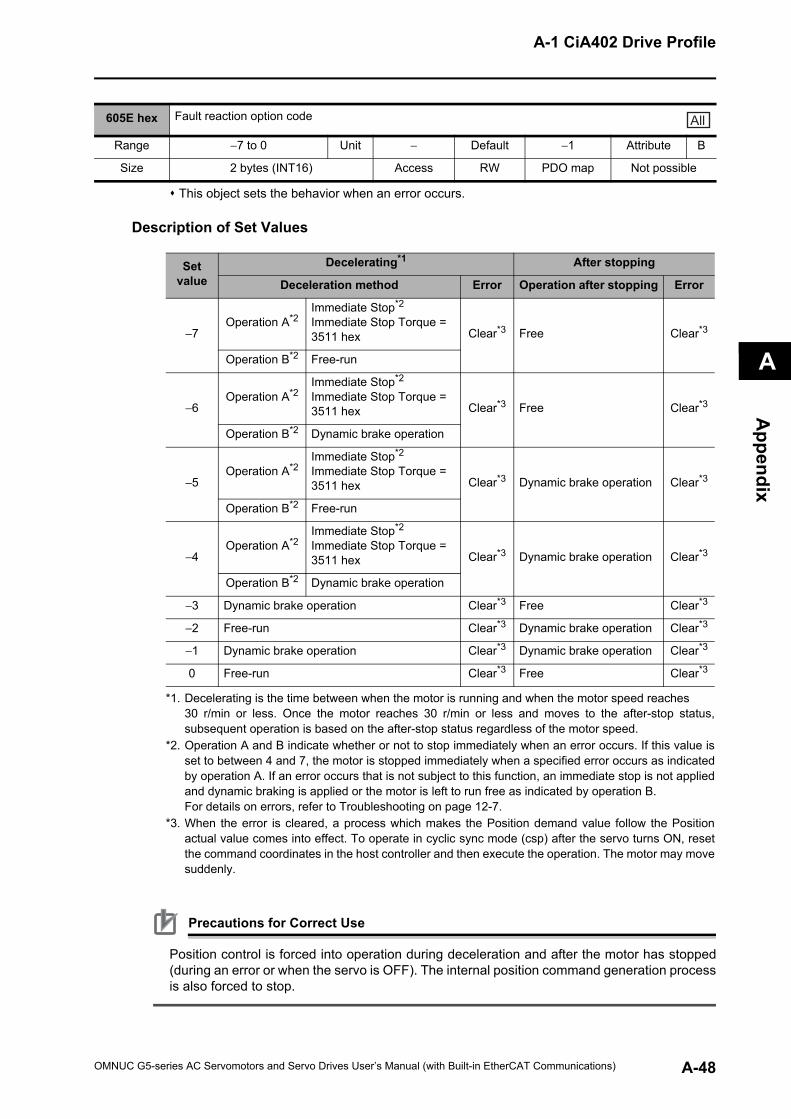
A-1 CiA402 Drive Profile
A
Appendix
This object sets the behavior when an error occurs.
Description of Set Values
Precautions for Correct Use
Position control is forced into operation during deceleration and after the motor has stopped(during an error or when the servo is OFF). The internal position command generation processis also forced to stop.
605E hex Fault reaction option code
Range −7 to 0 Unit − Default −1 Attribute B
Size 2 bytes (INT16) Access RW PDO map Not possible
All
Set value
Decelerating*1
*1. Decelerating is the time between when the motor is running and when the motor speed reaches 30 r/min or less. Once the motor reaches 30 r/min or less and moves to the after-stop status,subsequent operation is based on the after-stop status regardless of the motor speed.
After stopping
Deceleration method Error Operation after stopping Error
−7Operation A*2
*2. Operation A and B indicate whether or not to stop immediately when an error occurs. If this value isset to between 4 and 7, the motor is stopped immediately when a specified error occurs as indicatedby operation A. If an error occurs that is not subject to this function, an immediate stop is not appliedand dynamic braking is applied or the motor is left to run free as indicated by operation B.For details on errors, refer to Troubleshooting on page 12-7.
Immediate Stop*2
Immediate Stop Torque = 3511 hex Clear*3
*3. When the error is cleared, a process which makes the Position demand value follow the Positionactual value comes into effect. To operate in cyclic sync mode (csp) after the servo turns ON, resetthe command coordinates in the host controller and then execute the operation. The motor may movesuddenly.
Free Clear*3
Operation B*2 Free-run
−6Operation A*2
Immediate Stop*2
Immediate Stop Torque = 3511 hex Clear*3 Free Clear*3
Operation B*2 Dynamic brake operation
−5Operation A*2
Immediate Stop*2
Immediate Stop Torque = 3511 hex Clear*3 Dynamic brake operation Clear*3
Operation B*2 Free-run
−4Operation A*2
Immediate Stop*2
Immediate Stop Torque = 3511 hex Clear*3 Dynamic brake operation Clear*3
Operation B*2 Dynamic brake operation
−3 Dynamic brake operation Clear*3 Free Clear*3
−2 Free-run Clear*3 Dynamic brake operation Clear*3
−1 Dynamic brake operation Clear*3 Dynamic brake operation Clear*3
0 Free-run Clear*3 Free Clear*3
A-48OMNUC G5-series AC Servomotors and Servo Drives User’s Manual (with Built-in EtherCAT Communications)
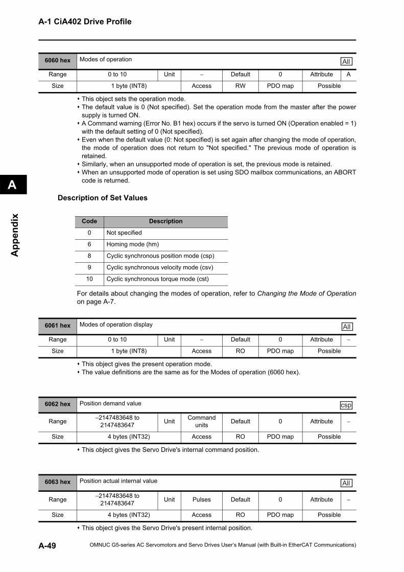
A-1 CiA402 Drive Profile
A
App
endi
x
This object sets the operation mode.The default value is 0 (Not specified). Set the operation mode from the master after the powersupply is turned ON.A Command warning (Error No. B1 hex) occurs if the servo is turned ON (Operation enabled = 1)with the default setting of 0 (Not specified).Even when the default value (0: Not specified) is set again after changing the mode of operation,the mode of operation does not return to "Not specified." The previous mode of operation isretained.Similarly, when an unsupported mode of operation is set, the previous mode is retained.When an unsupported mode of operation is set using SDO mailbox communications, an ABORTcode is returned.
Description of Set Values
For details about changing the modes of operation, refer to Changing the Mode of Operationon page A-7.
This object gives the present operation mode.The value definitions are the same as for the Modes of operation (6060 hex).
This object gives the Servo Drive's internal command position.
This object gives the Servo Drive's present internal position.
6060 hex Modes of operation
Range 0 to 10 Unit − Default 0 Attribute A
Size 1 byte (INT8) Access RW PDO map Possible
All
Code Description
0 Not specified
6 Homing mode (hm)
8 Cyclic synchronous position mode (csp)
9 Cyclic synchronous velocity mode (csv)
10 Cyclic synchronous torque mode (cst)
6061 hex Modes of operation display
Range 0 to 10 Unit − Default 0 Attribute −
Size 1 byte (INT8) Access RO PDO map Possible
All
6062 hex Position demand value
Range −2147483648 to 2147483647 Unit Command
units Default 0 Attribute −
Size 4 bytes (INT32) Access RO PDO map Possible
csp
6063 hex Position actual internal value
Range −2147483648 to 2147483647 Unit Pulses Default 0 Attribute −
Size 4 bytes (INT32) Access RO PDO map Possible
All
A-49 OMNUC G5-series AC Servomotors and Servo Drives User’s Manual (with Built-in EtherCAT Communications)
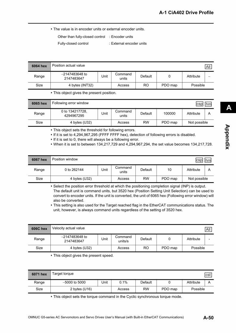
A-1 CiA402 Drive Profile
A
Appendix
The value is in encoder units or external encoder units.
This object gives the present position.
This object sets the threshold for following errors.If it is set to 4,294,967,295 (FFFF FFFF hex), detection of following errors is disabled.If it is set to 0, there will always be a following error.When it is set to between 134,217,729 and 4,294,967,294, the set value becomes 134,217,728.
Select the position error threshold at which the positioning completion signal (INP) is output.The default unit is command units, but 3520 hex (Position Setting Unit Selection) can be used toconvert to encoder units. If the unit is converted, the unit of 6065 hex (Following error window) willalso be converted.This setting is also used for the Target reached flag in the EtherCAT communications status. Theunit, however, is always command units regardless of the setting of 3520 hex.
This object gives the present speed.
This object sets the torque command in the Cyclic synchronous torque mode.
Other than fully-closed control : Encoder units
Fully-closed control : External encoder units
6064 hex Position actual value
Range −2147483648 to 2147483647 Unit Command
units Default 0 Attribute −
Size 4 bytes (INT32) Access RO PDO map Possible
All
6065 hex Following error window
Range 0 to 134217728, 4294967295 Unit Command
units Default 100000 Attribute A
Size 4 bytes (U32) Access RW PDO map Not possible
csp hm
6067 hex Position window
Range 0 to 262144 Unit Command units Default 10 Attribute A
Size 4 bytes (U32) Access RW PDO map Not possible
csp hm
606C hex Velocity actual value
Range −2147483648 to 2147483647 Unit Command
units/s Default 0 Attribute -
Size 4 bytes (U32) Access RO PDO map Possible
All
6071 hex Target torque
Range −5000 to 5000 Unit 0.1% Default 0 Attribute A
Size 2 bytes (U16) Access RW PDO map Possible
cst
A-50OMNUC G5-series AC Servomotors and Servo Drives User’s Manual (with Built-in EtherCAT Communications)
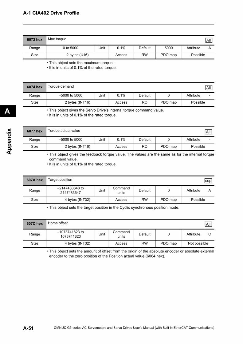
A-1 CiA402 Drive Profile
A
App
endi
x
This object sets the maximum torque.It is in units of 0.1% of the rated torque.
This object gives the Servo Drive's internal torque command value.It is in units of 0.1% of the rated torque.
This object gives the feedback torque value. The values are the same as for the internal torquecommand value.It is in units of 0.1% of the rated torque.
This object sets the target position in the Cyclic synchronous position mode.
This object sets the amount of offset from the origin of the absolute encoder or absolute externalencoder to the zero position of the Position actual value (6064 hex).
6072 hex Max torque
Range 0 to 5000 Unit 0.1% Default 5000 Attribute A
Size 2 bytes (U16) Access RW PDO map Possible
All
6074 hex Torque demand
Range −5000 to 5000 Unit 0.1% Default 0 Attribute -
Size 2 bytes (INT16) Access RO PDO map Possible
All
6077 hex Torque actual value
Range −5000 to 5000 Unit 0.1% Default 0 Attribute -
Size 2 bytes (INT16) Access RO PDO map Possible
All
607A hex Target position
Range −2147483648 to 2147483647 Unit Command
units Default 0 Attribute A
Size 4 bytes (INT32) Access RW PDO map Possible
csp
607C hex Home offset
Range −1073741823 to 1073741823 Unit Command
units Default 0 Attribute C
Size 4 bytes (INT32) Access RW PDO map Not possible
All
A-51 OMNUC G5-series AC Servomotors and Servo Drives User’s Manual (with Built-in EtherCAT Communications)
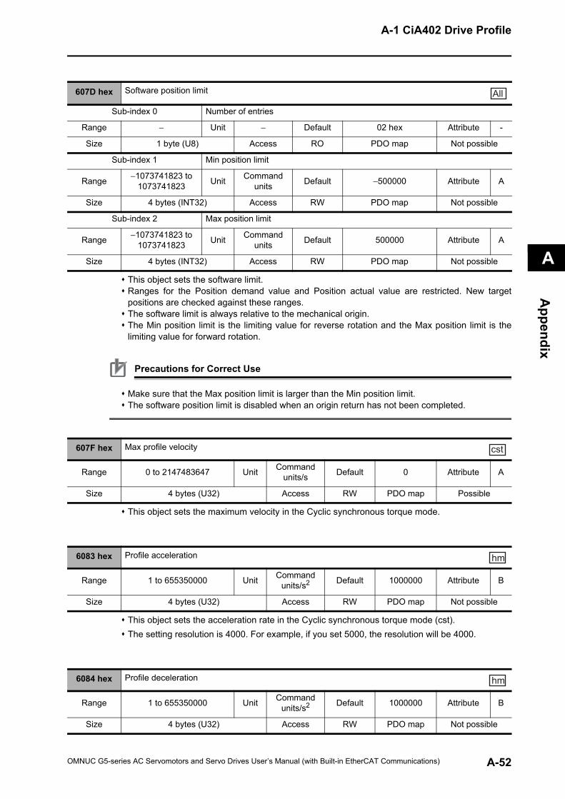
A-1 CiA402 Drive Profile
A
Appendix
This object sets the software limit.Ranges for the Position demand value and Position actual value are restricted. New targetpositions are checked against these ranges.The software limit is always relative to the mechanical origin.The Min position limit is the limiting value for reverse rotation and the Max position limit is thelimiting value for forward rotation.
Precautions for Correct Use
Make sure that the Max position limit is larger than the Min position limit.The software position limit is disabled when an origin return has not been completed.
This object sets the maximum velocity in the Cyclic synchronous torque mode.
This object sets the acceleration rate in the Cyclic synchronous torque mode (cst).The setting resolution is 4000. For example, if you set 5000, the resolution will be 4000.
607D hex Software position limit
Sub-index 0 Number of entries
Range − Unit − Default 02 hex Attribute -
Size 1 byte (U8) Access RO PDO map Not possible
Sub-index 1 Min position limit
Range −1073741823 to 1073741823 Unit Command
units Default −500000 Attribute A
Size 4 bytes (INT32) Access RW PDO map Not possible
Sub-index 2 Max position limit
Range −1073741823 to 1073741823 Unit Command
units Default 500000 Attribute A
Size 4 bytes (INT32) Access RW PDO map Not possible
All
607F hex Max profile velocity
Range 0 to 2147483647 Unit Command units/s Default 0 Attribute A
Size 4 bytes (U32) Access RW PDO map Possible
cst
6083 hex Profile acceleration
Range 1 to 655350000 Unit Command units/s2 Default 1000000 Attribute B
Size 4 bytes (U32) Access RW PDO map Not possible
hm
6084 hex Profile deceleration
Range 1 to 655350000 Unit Command units/s2 Default 1000000 Attribute B
Size 4 bytes (U32) Access RW PDO map Not possible
hm
A-52OMNUC G5-series AC Servomotors and Servo Drives User’s Manual (with Built-in EtherCAT Communications)
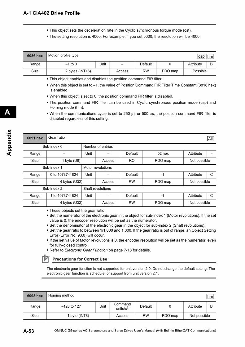
A-1 CiA402 Drive Profile
A
App
endi
x
This object sets the deceleration rate in the Cyclic synchronous torque mode (cst).The setting resolution is 4000. For example, if you set 5000, the resolution will be 4000.
This object enables and disables the position command FIR filter.When this object is set to −1, the value of Position Command FIR Filter Time Constant (3818 hex)is enabled.When this object is set to 0, the position command FIR filter is disabled.The position command FIR filter can be used in Cyclic synchronous position mode (csp) andHoming mode (hm).When the communications cycle is set to 250 µs or 500 µs, the position command FIR filter isdisabled regardless of this setting.
These objects set the gear ratio.Set the numerator of the electronic gear in the object for sub-index 1 (Motor revolutions). If the setvalue is 0, the encoder resolution will be set as the numerator.Set the denominator of the electronic gear in the object for sub-index 2 (Shaft revolutions).Set the gear ratio to between 1/1,000 and 1,000. If the gear ratio is out of range, an Object SettingError (Error No. 93.0) will occur. If the set value of Motor revolutions is 0, the encoder resolution will be set as the numerator, evenfor fully-closed control.Refer to Electronic Gear Function on page 7-18 for details.
Precautions for Correct Use
The electronic gear function is not supported for unit version 2.0. Do not change the default setting. The electronic gear function is schedule for support from unit version 2.1.
6086 hex Motion profile type
Range −1 to 0 Unit − Default 0 Attribute B
Size 2 bytes (INT16) Access RW PDO map Possible
hmcsp
6091 hex Gear ratio
Sub-index 0 Number of entries
Range − Unit − Default 02 hex Attribute −
Size 1 byte (U8) Access RO PDO map Not possible
Sub-index 1 Motor revolutions
Range 0 to 1073741824 Unit − Default 1 Attribute C
Size 4 bytes (U32) Access RW PDO map Not possible
Sub-index 2 Shaft revolutions
Range 1 to 1073741824 Unit − Default 1 Attribute C
Size 4 bytes (U32) Access RW PDO map Not possible
All
6098 hex Homing method
Range −128 to 127 Unit Command units/s2 Default 0 Attribute B
Size 1 byte (INT8) Access RW PDO map Not possible
hm
A-53 OMNUC G5-series AC Servomotors and Servo Drives User’s Manual (with Built-in EtherCAT Communications)
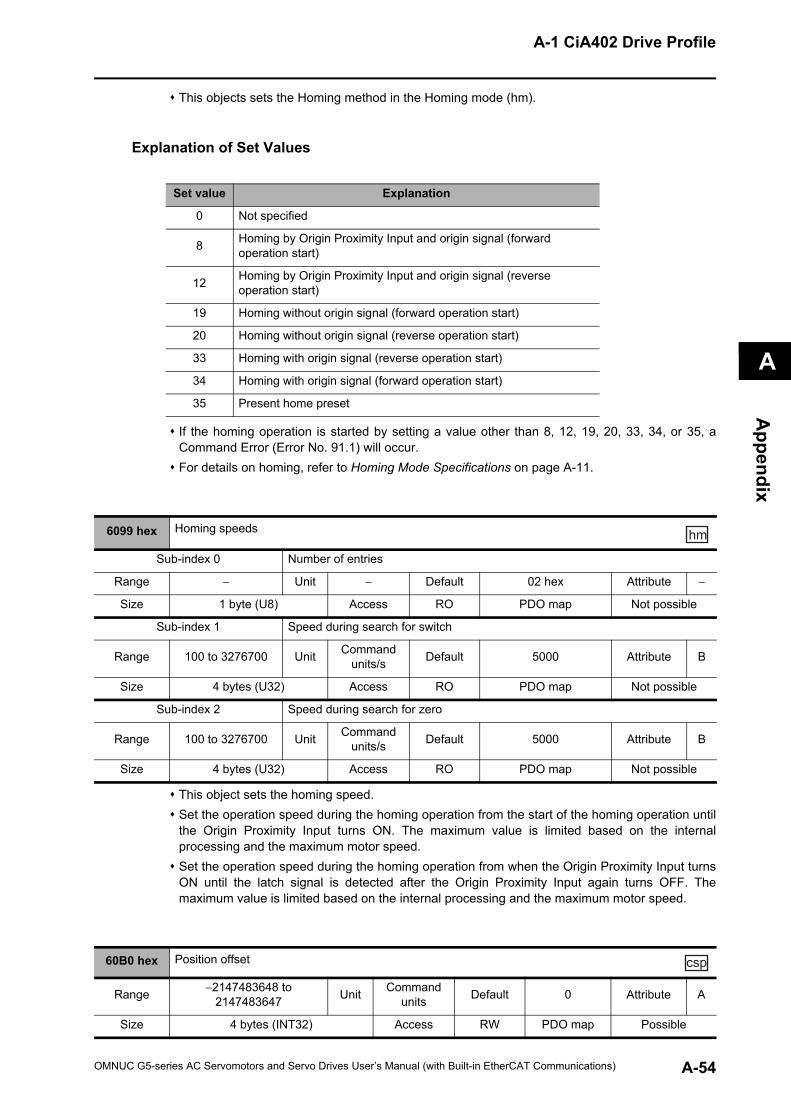
A-1 CiA402 Drive Profile
A
Appendix
This objects sets the Homing method in the Homing mode (hm).
Explanation of Set Values
If the homing operation is started by setting a value other than 8, 12, 19, 20, 33, 34, or 35, aCommand Error (Error No. 91.1) will occur.For details on homing, refer to Homing Mode Specifications on page A-11.
This object sets the homing speed.Set the operation speed during the homing operation from the start of the homing operation untilthe Origin Proximity Input turns ON. The maximum value is limited based on the internalprocessing and the maximum motor speed.Set the operation speed during the homing operation from when the Origin Proximity Input turnsON until the latch signal is detected after the Origin Proximity Input again turns OFF. Themaximum value is limited based on the internal processing and the maximum motor speed.
Set value Explanation
0 Not specified
8 Homing by Origin Proximity Input and origin signal (forward operation start)
12 Homing by Origin Proximity Input and origin signal (reverse operation start)
19 Homing without origin signal (forward operation start)
20 Homing without origin signal (reverse operation start)
33 Homing with origin signal (reverse operation start)
34 Homing with origin signal (forward operation start)
35 Present home preset
6099 hex Homing speeds
Sub-index 0 Number of entries
Range − Unit − Default 02 hex Attribute −
Size 1 byte (U8) Access RO PDO map Not possible
Sub-index 1 Speed during search for switch
Range 100 to 3276700 Unit Command units/s Default 5000 Attribute B
Size 4 bytes (U32) Access RO PDO map Not possible
Sub-index 2 Speed during search for zero
Range 100 to 3276700 Unit Command units/s Default 5000 Attribute B
Size 4 bytes (U32) Access RO PDO map Not possible
hm
60B0 hex Position offset
Range −2147483648 to 2147483647 Unit Command
units Default 0 Attribute A
Size 4 bytes (INT32) Access RW PDO map Possible
csp
A-54OMNUC G5-series AC Servomotors and Servo Drives User’s Manual (with Built-in EtherCAT Communications)
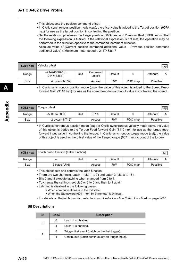
A-1 CiA402 Drive Profile
A
App
endi
x
This object sets the position command offset.In Cyclic synchronous position mode (csp), the offset value is added to the Target position (607Ahex) for use as the target position in controlling the position.Set the relationship between the Target position (607A hex) and Position offset (60B0 hex) so thatthe following expression is fulfilled. If the relational expression is not met, the operation may beperformed in the direction opposite to the command increment direction.Absolute value of (Current position command additional value − Previous position commandadditional value) ≤ Maximum motor speed ≤ 2147483647
In Cyclic synchronous position mode (csp), the value of this object is added to the Speed Feed-forward Gain (3110 hex) for use as the speed feed-forward input value in controlling the speed.
In Cyclic synchronous position mode (csp) or Cyclic synchronous velocity mode (csv), the valueof this object is added to the Torque Feed-forward Gain (3112 hex) for use as the torque feed-forward input value in controlling the torque. In Cyclic synchronous torque mode (cst), the valueof this object is used as the offset value of the Target torque (6071 hex) to control the torque.
This object sets and controls the latch function.There are two channels, Latch 1 (bits 1 to 7) and Latch 2 (bits 8 to 15).Bits 0 and 8 execute latching when changed from 0 to 1.To change the settings, set bit 0 or 8 to 0 and then to 1 again.Latching is disabled in the following cases.
When communications is in the Init state. When the Statusword (6041 hex) bit 9 (remote) is 0 (local).
For details on the latch function, refer to Touch Probe Function (Latch Function) on page 7-37.
Bit Descriptions
60B1 hex Velocity offset
Range −2147483648 to 2147483647 Unit Command
units/s Default 0 Attribute A
Size 4 bytes (INT32) Access RW PDO map Possible
csp
60B2 hex Torque offset
Range −5000 to 5000 Unit 0.1% Default 0 Attribute A
Size 2 bytes (INT16) Access RW PDO map Possible
csp
60B8 hex Touch probe function (Latch function)
Range − Unit − Default 0 Attribute A
Size 2 bytes (U16) Access RW PDO map Possible
All
Bit Code Description
00 Latch 1 is disabled.
1 Latch 1 is enabled.
10 Trigger first event (Latch on the first trigger).
1 Continuous (Latch continuously on trigger input).
A-55 OMNUC G5-series AC Servomotors and Servo Drives User’s Manual (with Built-in EtherCAT Communications)
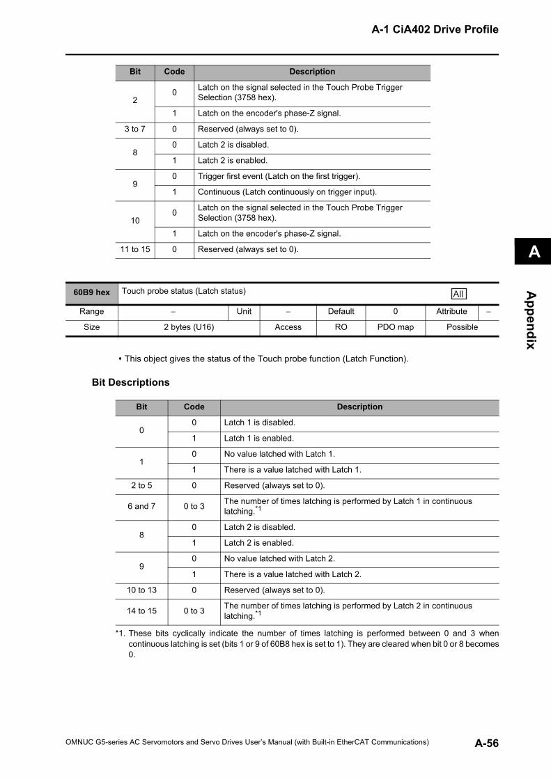
A-1 CiA402 Drive Profile
A
Appendix
This object gives the status of the Touch probe function (Latch Function).
Bit Descriptions
20 Latch on the signal selected in the Touch Probe Trigger
Selection (3758 hex).
1 Latch on the encoder's phase-Z signal.
3 to 7 0 Reserved (always set to 0).
80 Latch 2 is disabled.
1 Latch 2 is enabled.
90 Trigger first event (Latch on the first trigger).
1 Continuous (Latch continuously on trigger input).
100 Latch on the signal selected in the Touch Probe Trigger
Selection (3758 hex).
1 Latch on the encoder's phase-Z signal.
11 to 15 0 Reserved (always set to 0).
Bit Code Description
60B9 hex Touch probe status (Latch status)
Range − Unit − Default 0 Attribute −
Size 2 bytes (U16) Access RO PDO map Possible
All
Bit Code Description
00 Latch 1 is disabled.
1 Latch 1 is enabled.
10 No value latched with Latch 1.
1 There is a value latched with Latch 1.
2 to 5 0 Reserved (always set to 0).
6 and 7 0 to 3 The number of times latching is performed by Latch 1 in continuous latching.*1
80 Latch 2 is disabled.
1 Latch 2 is enabled.
90 No value latched with Latch 2.
1 There is a value latched with Latch 2.
10 to 13 0 Reserved (always set to 0).
14 to 15 0 to 3 The number of times latching is performed by Latch 2 in continuous latching.*1
*1. These bits cyclically indicate the number of times latching is performed between 0 and 3 whencontinuous latching is set (bits 1 or 9 of 60B8 hex is set to 1). They are cleared when bit 0 or 8 becomes0.
A-56OMNUC G5-series AC Servomotors and Servo Drives User’s Manual (with Built-in EtherCAT Communications)
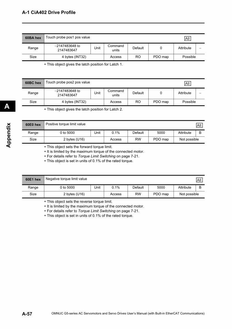
A-1 CiA402 Drive Profile
A
App
endi
x
This object gives the latch position for Latch 1.
This object gives the latch position for Latch 2.
This object sets the forward torque limit.It is limited by the maximum torque of the connected motor.For details refer to Torque Limit Switching on page 7-21. This object is set in units of 0.1% of the rated torque.
This object sets the reverse torque limit.It is limited by the maximum torque of the connected motor.For details refer to Torque Limit Switching on page 7-21. This object is set in units of 0.1% of the rated torque.
60BA hex Touch probe pos1 pos value
Range −2147483648 to 2147483647 Unit Command
units Default 0 Attribute −
Size 4 bytes (INT32) Access RO PDO map Possible
All
60BC hex Touch probe pos2 pos value
Range −2147483648 to 2147483647 Unit Command
units Default 0 Attribute −
Size 4 bytes (INT32) Access RO PDO map Possible
All
60E0 hex Positive torque limit value
Range 0 to 5000 Unit 0.1% Default 5000 Attribute B
Size 2 bytes (U16) Access RW PDO map Not possible
All
60E1 hex Negative torque limit value
Range 0 to 5000 Unit 0.1% Default 5000 Attribute B
Size 2 bytes (U16) Access RW PDO map Not possible
All
A-57 OMNUC G5-series AC Servomotors and Servo Drives User’s Manual (with Built-in EtherCAT Communications)
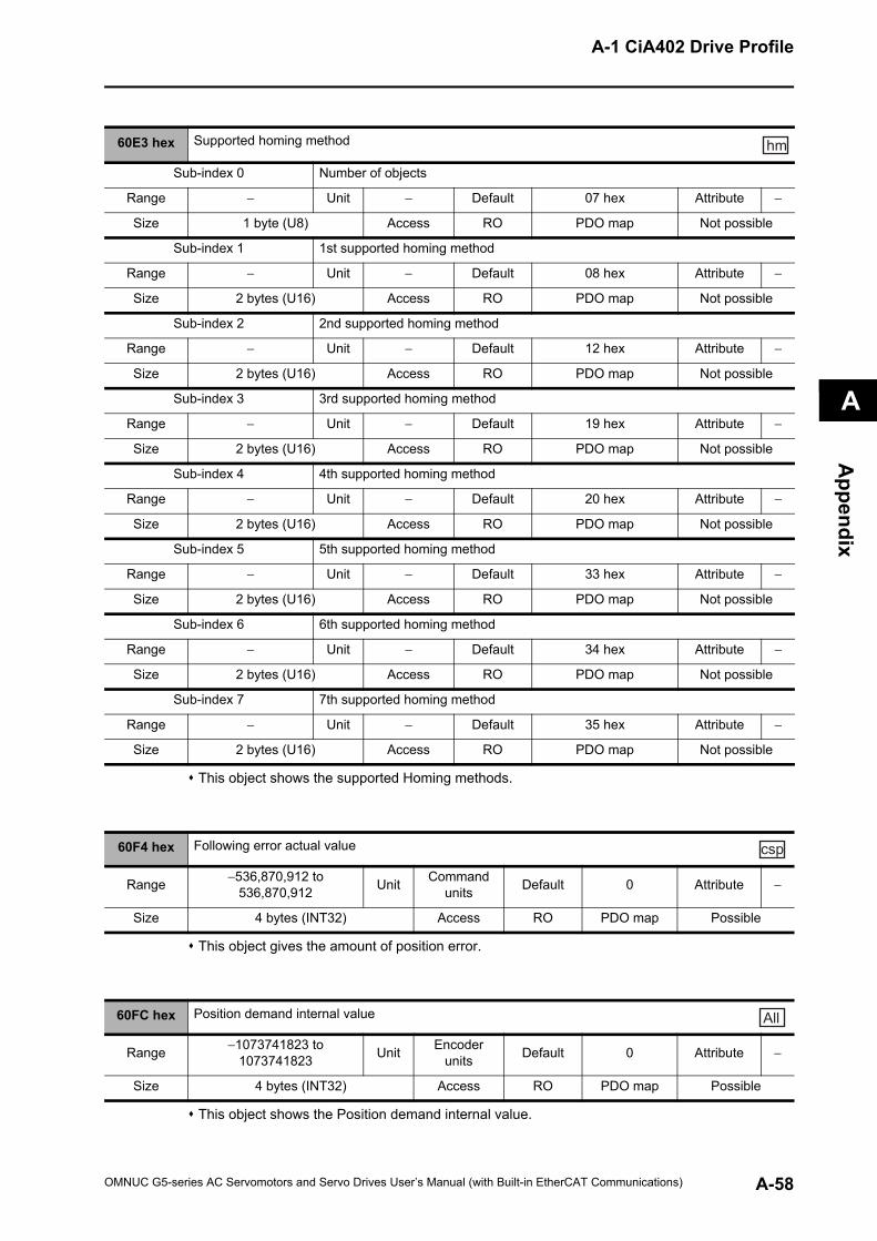
A-1 CiA402 Drive Profile
A
Appendix
This object shows the supported Homing methods.
This object gives the amount of position error.
This object shows the Position demand internal value.
60E3 hex Supported homing method
Sub-index 0 Number of objects
Range − Unit − Default 07 hex Attribute −
Size 1 byte (U8) Access RO PDO map Not possible
Sub-index 1 1st supported homing method
Range − Unit − Default 08 hex Attribute −
Size 2 bytes (U16) Access RO PDO map Not possible
Sub-index 2 2nd supported homing method
Range − Unit − Default 12 hex Attribute −
Size 2 bytes (U16) Access RO PDO map Not possible
Sub-index 3 3rd supported homing method
Range − Unit − Default 19 hex Attribute −
Size 2 bytes (U16) Access RO PDO map Not possible
Sub-index 4 4th supported homing method
Range − Unit − Default 20 hex Attribute −
Size 2 bytes (U16) Access RO PDO map Not possible
Sub-index 5 5th supported homing method
Range − Unit − Default 33 hex Attribute −
Size 2 bytes (U16) Access RO PDO map Not possible
Sub-index 6 6th supported homing method
Range − Unit − Default 34 hex Attribute −
Size 2 bytes (U16) Access RO PDO map Not possible
Sub-index 7 7th supported homing method
Range − Unit − Default 35 hex Attribute −
Size 2 bytes (U16) Access RO PDO map Not possible
hm
60F4 hex Following error actual value
Range −536,870,912 to 536,870,912 Unit Command
units Default 0 Attribute −
Size 4 bytes (INT32) Access RO PDO map Possible
csp
60FC hex Position demand internal value
Range −1073741823 to 1073741823 Unit Encoder
units Default 0 Attribute −
Size 4 bytes (INT32) Access RO PDO map Possible
All
A-58OMNUC G5-series AC Servomotors and Servo Drives User’s Manual (with Built-in EtherCAT Communications)
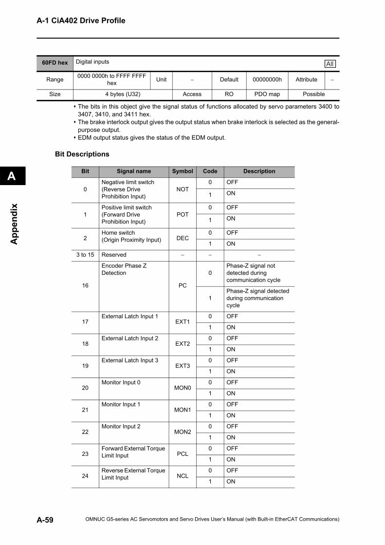
A-1 CiA402 Drive Profile
A
App
endi
x
The bits in this object give the signal status of functions allocated by servo parameters 3400 to3407, 3410, and 3411 hex.The brake interlock output gives the output status when brake interlock is selected as the general-purpose output.EDM output status gives the status of the EDM output.
Bit Descriptions
60FD hex Digital inputs
Range 0000 0000h to FFFF FFFF hex Unit − Default 00000000h Attribute −
Size 4 bytes (U32) Access RO PDO map Possible
All
Bit Signal name Symbol Code Description
0Negative limit switch (Reverse Drive Prohibition Input)
NOT0 OFF
1 ON
1Positive limit switch (Forward Drive Prohibition Input)
POT0 OFF
1 ON
2Home switch (Origin Proximity Input) DEC
0 OFF
1 ON
3 to 15 Reserved − − −
16
Encoder Phase Z Detection
PC
0Phase-Z signal not detected during communication cycle
1Phase-Z signal detected during communication cycle
17External Latch Input 1
EXT10 OFF
1 ON
18External Latch Input 2
EXT20 OFF
1 ON
19External Latch Input 3
EXT30 OFF
1 ON
20Monitor Input 0
MON00 OFF
1 ON
21Monitor Input 1
MON10 OFF
1 ON
22Monitor Input 2
MON20 OFF
1 ON
23Forward External Torque Limit Input PCL
0 OFF
1 ON
24Reverse External Torque Limit Input NCL
0 OFF
1 ON
A-59 OMNUC G5-series AC Servomotors and Servo Drives User’s Manual (with Built-in EtherCAT Communications)
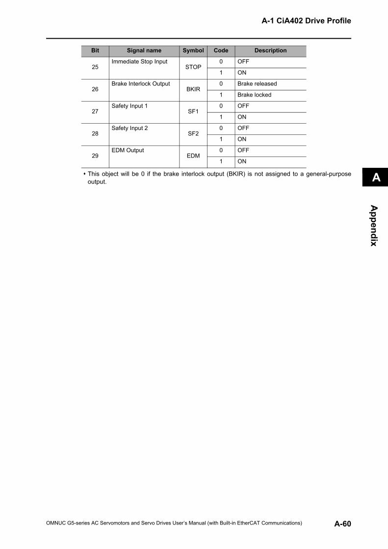
A-1 CiA402 Drive Profile
A
Appendix
This object will be 0 if the brake interlock output (BKIR) is not assigned to a general-purposeoutput.
25Immediate Stop Input
STOP0 OFF
1 ON
26Brake Interlock Output
BKIR0 Brake released
1 Brake locked
27Safety Input 1
SF10 OFF
1 ON
28Safety Input 2
SF20 OFF
1 ON
29EDM Output
EDM0 OFF
1 ON
Bit Signal name Symbol Code Description
A-60OMNUC G5-series AC Servomotors and Servo Drives User’s Manual (with Built-in EtherCAT Communications)
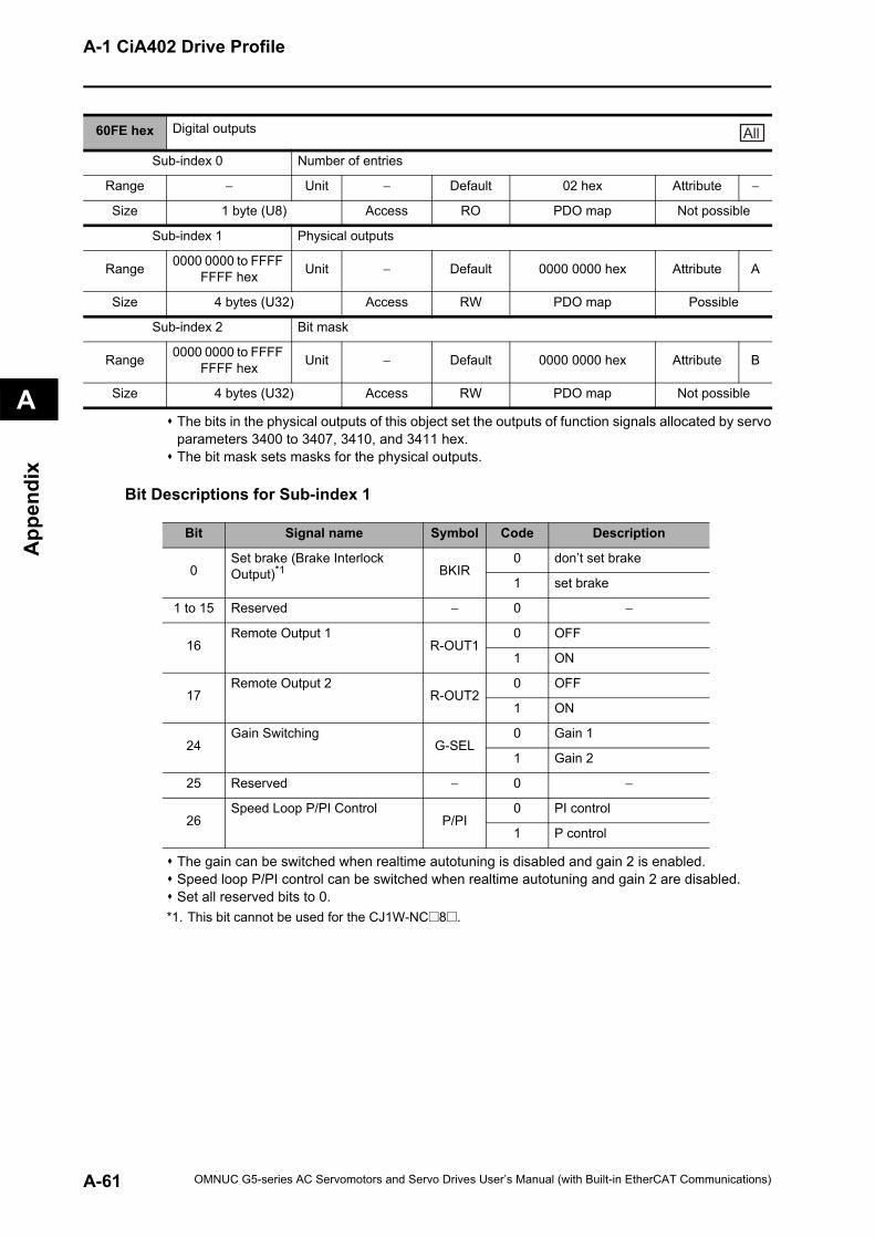
A-1 CiA402 Drive Profile
A
App
endi
x
The bits in the physical outputs of this object set the outputs of function signals allocated by servoparameters 3400 to 3407, 3410, and 3411 hex.The bit mask sets masks for the physical outputs.
Bit Descriptions for Sub-index 1
The gain can be switched when realtime autotuning is disabled and gain 2 is enabled. Speed loop P/PI control can be switched when realtime autotuning and gain 2 are disabled. Set all reserved bits to 0.
*1. This bit cannot be used for the CJ1W-NC@8@.
60FE hex Digital outputs
Sub-index 0 Number of entries
Range − Unit − Default 02 hex Attribute −
Size 1 byte (U8) Access RO PDO map Not possible
Sub-index 1 Physical outputs
Range 0000 0000 to FFFF FFFF hex Unit − Default 0000 0000 hex Attribute A
Size 4 bytes (U32) Access RW PDO map Possible
Sub-index 2 Bit mask
Range 0000 0000 to FFFF FFFF hex Unit − Default 0000 0000 hex Attribute B
Size 4 bytes (U32) Access RW PDO map Not possible
All
Bit Signal name Symbol Code Description
0Set brake (Brake Interlock Output)*1 BKIR
0 don’t set brake
1 set brake
1 to 15 Reserved − 0 −
16Remote Output 1
R-OUT10 OFF
1 ON
17Remote Output 2
R-OUT20 OFF
1 ON
24Gain Switching
G-SEL0 Gain 1
1 Gain 2
25 Reserved − 0 −
26Speed Loop P/PI Control
P/PI0 PI control
1 P control
A-61 OMNUC G5-series AC Servomotors and Servo Drives User’s Manual (with Built-in EtherCAT Communications)
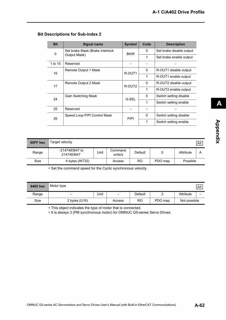
A-1 CiA402 Drive Profile
A
Appendix
Bit Descriptions for Sub-index 2
Set the command speed for the Cyclic synchronous velocity.
This object indicates the type of motor that is connected.It is always 3 (PM synchronous motor) for OMNUC G5-series Servo Drives.
Bit Signal name Symbol Code Description
0Set brake Mask (Brake Interlock Output Mask) BKIR
0 Set brake disable output
1 Set brake enable output
1 to 15 Reserved − − −
16Remote Output 1 Mask
R-OUT10 R-OUT1 disable output
1 R-OUT1 enable output
17Remote Output 2 Mask
R-OUT20 R-OUT2 disable output
1 R-OUT2 enable output
24Gain Switching Mask
G-SEL0 Switch setting disable
1 Switch setting enable
25 Reserved − − −
26Speed Loop P/PI Control Mask
P/PI0 Switch setting disable
1 Switch setting enable
60FF hex Target velocity
Range −2147483647 to 2147483647 Unit Command
units/s Default 0 Attribute A
Size 4 bytes (INT32) Access RO PDO map Possible
All
6402 hex Motor type
Range − Unit − Default 3 Attribute −
Size 2 bytes (U16) Access RO PDO map Not possible
All
A-62OMNUC G5-series AC Servomotors and Servo Drives User’s Manual (with Built-in EtherCAT Communications)
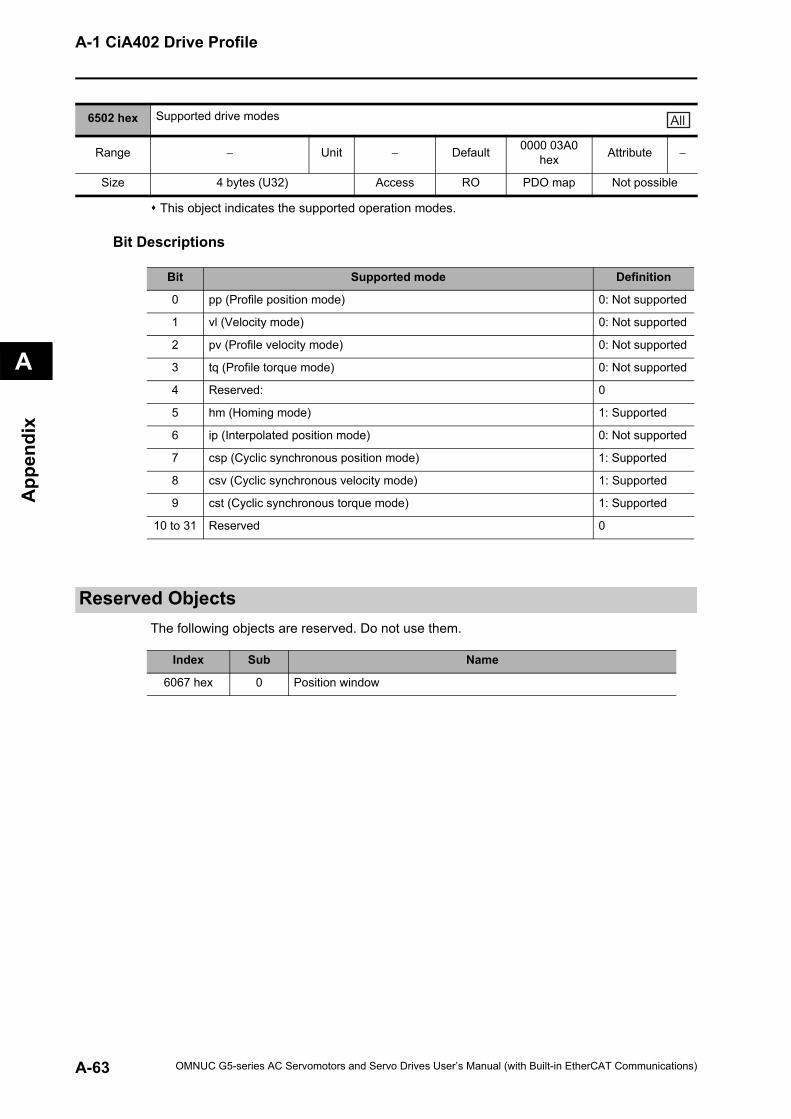
A-1 CiA402 Drive Profile
A
App
endi
x
This object indicates the supported operation modes.
Bit Descriptions
Reserved ObjectsThe following objects are reserved. Do not use them.
6502 hex Supported drive modes
Range − Unit − Default 0000 03A0 hex Attribute −
Size 4 bytes (U32) Access RO PDO map Not possible
All
Bit Supported mode Definition
0 pp (Profile position mode) 0: Not supported
1 vl (Velocity mode) 0: Not supported
2 pv (Profile velocity mode) 0: Not supported
3 tq (Profile torque mode) 0: Not supported
4 Reserved: 0
5 hm (Homing mode) 1: Supported
6 ip (Interpolated position mode) 0: Not supported
7 csp (Cyclic synchronous position mode) 1: Supported
8 csv (Cyclic synchronous velocity mode) 1: Supported
9 cst (Cyclic synchronous torque mode) 1: Supported
10 to 31 Reserved 0
Index Sub Name
6067 hex 0 Position window
A-63 OMNUC G5-series AC Servomotors and Servo Drives User’s Manual (with Built-in EtherCAT Communications)
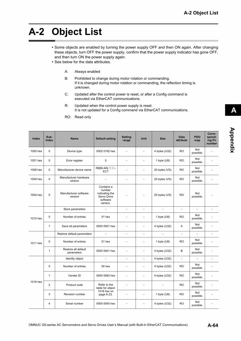
A-2 Object List
A
Appendix
A-2 Object ListSome objects are enabled by turning the power supply OFF and then ON again. After changingthese objects, turn OFF the power supply, confirm that the power supply indicator has gone OFF,and then turn ON the power supply again.See below for the data attributes.
A: Always enabled
B: Prohibited to change during motor rotation or commanding.If it is changed during motor rotation or commanding, the reflection timing is unknown.
C: Updated after the control power is reset, or after a Config command is executed via EtherCAT communications.
R: Updated when the control power supply is reset.It is not updated for a Config command via EtherCAT communications.
RO: Read only
Index Sub-Index Name Default setting Setting
range Unit Size Data attribute
PDO map
Corre-spond-ing Pn
number
1000 hex 0 Device type 0002 0192 hex − − 4 bytes (U32) RO Not possible. −
1001 hex 0 Error register 0 − − 1 byte (U8) RO Not possible. −
1008 hex 0 Manufacturer device name R88D-KN@@@-ECT − − 20 bytes (VS) RO Not
possible. −
1009 hex 0 Manufacturer hardware version − − − 20 bytes (VS) RO Not
possible. −
100A hex 0 Manufacturer software version
Contains a number
indicating the Servo Drive
software version.
− − 20 bytes (VS) RO Not possible. −
1010 hex
Store parameters − − − − − − −
0 Number of entries 01 hex − − 1 byte (U8) RO Not possible. −
1 Save all parameters 0000 0001 hex − − 4 bytes (U32) A Not possible. −
1011 hex
Restore default parameters − − − − − − −
0 Number of entries 01 hex − − 1 byte (U8) RO Not possible. −
1 Restore all default parameters 0000 0001 hex − − 4 bytes (U32) B Not
possible. −
1018 hex
Identity object - − − 4 bytes (U32) − − −
0 Number of entries 04 hex − − 4 bytes (U32) RO Not possible. −
1 Vender ID 0000 0083 hex − − 4 bytes (U32) RO Not possible. −
2 Product code Refer to the table for object 1018 hex on page A-23.
− − − RO Not possible. −
3 Revision number − − 1 byte (U8) RO Not possible. −
4 Serial number 0000 0000 hex − − 4 bytes (U32) RO Not possible. −
A-64OMNUC G5-series AC Servomotors and Servo Drives User’s Manual (with Built-in EtherCAT Communications)
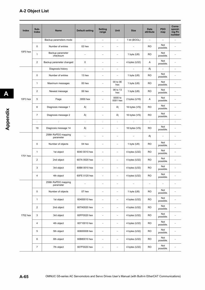
A-2 Object List
A
App
endi
x
10F0 hex
Backup parameters mode − − − 1 bit (BOOL) − − −
0 Number of entries 02 hex − − - RO Not possible. −
1 Backup parameter checksum − − − 1 byte (U8) RO Not
possible. −
2 Backup parameter changed 0 − − 4 bytes (U32) A Not possible. −
10F3 hex
Diagnosis history − − − - Å| - −
0 Number of entries 13 hex − − 1 byte (U8) RO Not possible. −
1 Maximum messages 00 hex − 00 to 0E hex 1 byte (U8) RO Not
possible. −
2 Newest message 06 hex − 06 to 13 hex 1 byte (U8) RO Not
possible. −
5 Flags 0000 hex − 0000 to 0001 hex 2 bytes (U16) A Not
possible. −
6 Diagnosis message 1 Å| − Å| 16 bytes (VS) RO Not possible. −
7 Diagnosis message 2 Å| − Å| 16 bytes (VS) RO Not possible. −
: : : : : : : : :
19 Diagnosis message 14 Å| − − 16 bytes (VS) RO Not possible. −
1701 hex
258th RxPDO mapping parameter - − − − Å| - −
0 Number of objects 04 hex − − 1 byte (U8) RO Not possible. −
1 1st object 6040 0010 hex − − 4 bytes (U32) RO Not possible. −
2 2nd object 607A 0020 hex − − 4 bytes (U32) RO Not possible. −
3 3rd object 60B8 0010 hex − − 4 bytes (U32) RO Not possible. −
4 4th object 60FE 0120 hex − − 4 bytes (U32) RO Not possible. −
1702 hex
259th RxPDO mapping parameter − − − − − − −
0 Number of objects 07 hex − − 1 byte (U8) RO Not possible. −
1 1st object 60400010 hex − − 4 bytes (U32) RO Not possible. −
2 2nd object 607A0020 hex − − 4 bytes (U32) RO Not possible. −
3 3rd object 60FF0020 hex − − 4 bytes (U32) RO Not possible. −
4 4th object 60710010 hex − − 4 bytes (U32) RO Not possible. −
5 5th object 60600008 hex − − 4 bytes (U32) RO Not possible. −
6 6th object 60B80010 hex − − 4 bytes (U32) RO Not possible. −
7 7th object 607F0020 hex − − 4 bytes (U32) RO Not possible. −
Index Sub-Index Name Default setting Setting
range Unit Size Data attribute
PDO map
Corre-spond-ing Pn
number
A-65 OMNUC G5-series AC Servomotors and Servo Drives User’s Manual (with Built-in EtherCAT Communications)
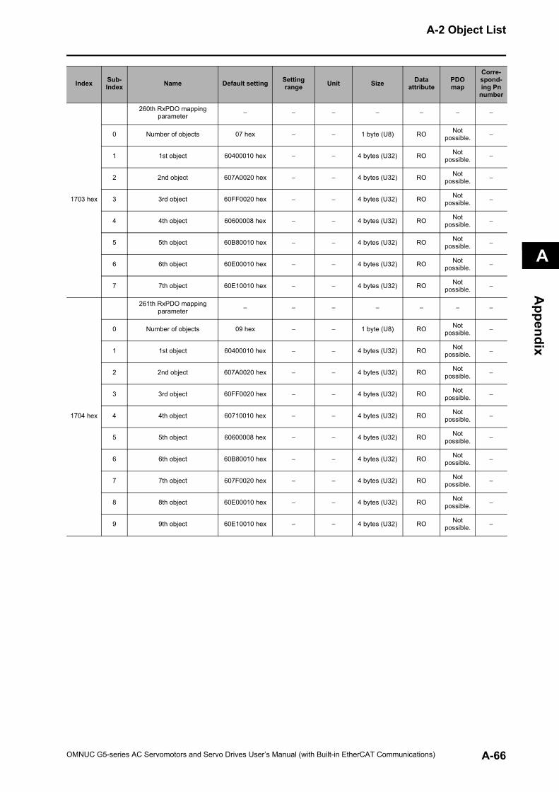
A-2 Object List
A
Appendix
1703 hex
260th RxPDO mapping parameter − − − − − − −
0 Number of objects 07 hex − − 1 byte (U8) RO Not possible. −
1 1st object 60400010 hex − − 4 bytes (U32) RO Not possible. −
2 2nd object 607A0020 hex − − 4 bytes (U32) RO Not possible. −
3 3rd object 60FF0020 hex − − 4 bytes (U32) RO Not possible. −
4 4th object 60600008 hex − − 4 bytes (U32) RO Not possible. −
5 5th object 60B80010 hex − − 4 bytes (U32) RO Not possible. −
6 6th object 60E00010 hex − − 4 bytes (U32) RO Not possible. −
7 7th object 60E10010 hex − − 4 bytes (U32) RO Not possible. −
1704 hex
261th RxPDO mapping parameter − − − − − − −
0 Number of objects 09 hex − − 1 byte (U8) RO Not possible. −
1 1st object 60400010 hex − − 4 bytes (U32) RO Not possible. −
2 2nd object 607A0020 hex − − 4 bytes (U32) RO Not possible. −
3 3rd object 60FF0020 hex − − 4 bytes (U32) RO Not possible. −
4 4th object 60710010 hex − − 4 bytes (U32) RO Not possible. −
5 5th object 60600008 hex − − 4 bytes (U32) RO Not possible. −
6 6th object 60B80010 hex − − 4 bytes (U32) RO Not possible. −
7 7th object 607F0020 hex − − 4 bytes (U32) RO Not possible. −
8 8th object 60E00010 hex − − 4 bytes (U32) RO Not possible. −
9 9th object 60E10010 hex − − 4 bytes (U32) RO Not possible. −
Index Sub-Index Name Default setting Setting
range Unit Size Data attribute
PDO map
Corre-spond-ing Pn
number
A-66OMNUC G5-series AC Servomotors and Servo Drives User’s Manual (with Built-in EtherCAT Communications)
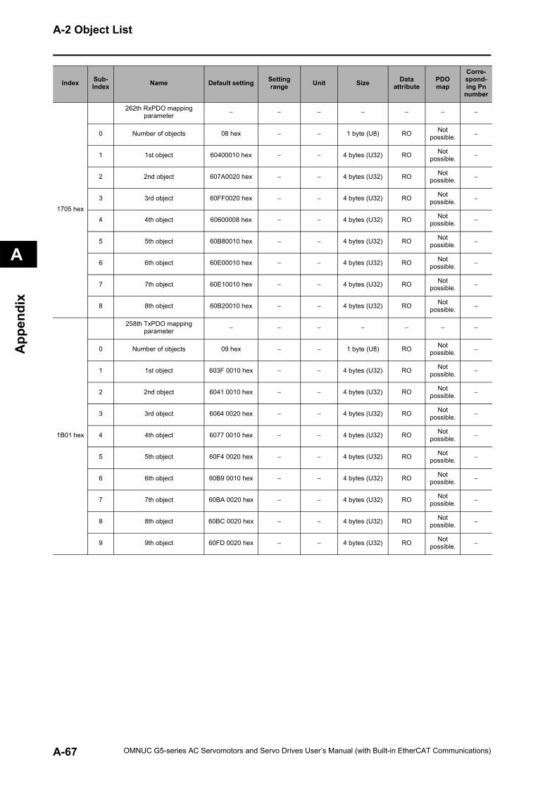
A-2 Object List
A
App
endi
x
1705 hex
262th RxPDO mapping parameter − − − − − − −
0 Number of objects 08 hex − − 1 byte (U8) RO Not possible. −
1 1st object 60400010 hex − − 4 bytes (U32) RO Not possible. −
2 2nd object 607A0020 hex − − 4 bytes (U32) RO Not possible. −
3 3rd object 60FF0020 hex − − 4 bytes (U32) RO Not possible. −
4 4th object 60600008 hex − − 4 bytes (U32) RO Not possible. −
5 5th object 60B80010 hex − − 4 bytes (U32) RO Not possible. −
6 6th object 60E00010 hex − − 4 bytes (U32) RO Not possible. −
7 7th object 60E10010 hex − − 4 bytes (U32) RO Not possible. −
8 8th object 60B20010 hex − − 4 bytes (U32) RO Not possible. −
1B01 hex
258th TxPDO mapping parameter − − − − − − −
0 Number of objects 09 hex − − 1 byte (U8) RO Not possible. −
1 1st object 603F 0010 hex − − 4 bytes (U32) RO Not possible. −
2 2nd object 6041 0010 hex − − 4 bytes (U32) RO Not possible. −
3 3rd object 6064 0020 hex − − 4 bytes (U32) RO Not possible. −
4 4th object 6077 0010 hex − − 4 bytes (U32) RO Not possible. −
5 5th object 60F4 0020 hex − − 4 bytes (U32) RO Not possible. −
6 6th object 60B9 0010 hex − − 4 bytes (U32) RO Not possible. −
7 7th object 60BA 0020 hex − − 4 bytes (U32) RO Not possible. −
8 8th object 60BC 0020 hex − − 4 bytes (U32) RO Not possible. −
9 9th object 60FD 0020 hex − − 4 bytes (U32) RO Not possible. −
Index Sub-Index Name Default setting Setting
range Unit Size Data attribute
PDO map
Corre-spond-ing Pn
number
A-67 OMNUC G5-series AC Servomotors and Servo Drives User’s Manual (with Built-in EtherCAT Communications)
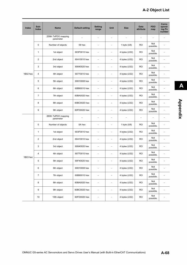
A-2 Object List
A
Appendix
1B02 hex
259th TxPDO mapping parameter − − − − − − −
0 Number of objects 09 hex − − 1 byte (U8) RO Not possible. −
1 1st object 603F0010 hex − − 4 bytes (U32) RO Not possible. −
2 2nd object 60410010 hex − − 4 bytes (U32) RO Not possible. −
3 3rd object 60640020 hex − − 4 bytes (U32) RO Not possible. −
4 4th object 60770010 hex − − 4 bytes (U32) RO Not possible. −
5 5th object 60610008 hex − − 4 bytes (U32) RO Not possible. −
6 6th object 60B90010 hex − − 4 bytes (U32) RO Not possible. −
7 7th object 60BA0020 hex − − 4 bytes (U32) RO Not possible. −
8 8th object 60BC0020 hex − − 4 bytes (U32) RO Not possible. −
9 9th object 60FD0020 hex − − 4 bytes (U32) RO Not possible. −
1B03 hex
260th TxPDO mapping parameter − − − − − − −
0 Number of objects 0A hex − − 1 byte (U8) RO Not possible. −
1 1st object 603F0010 hex − − 4 bytes (U32) RO Not possible. −
2 2nd object 60410010 hex − − 4 bytes (U32) RO Not possible. −
3 3rd object 60640020 hex − − 4 bytes (U32) RO Not possible. −
4 4th object 60770010 hex − − 4 bytes (U32) RO Not possible. −
5 5th object 60F40020 hex − − 4 bytes (U32) RO Not possible. −
6 6th object 60610008 hex − − 4 bytes (U32) RO Not possible. −
7 7th object 60B90010 hex − − 4 bytes (U32) RO Not possible. −
8 8th object 60BA0020 hex − − 4 bytes (U32) RO Not possible. −
9 9th object 60BC0020 hex − − 4 bytes (U32) RO Not possible. −
10 10th object 60FD0020 hex − − 4 bytes (U32) RO Not possible. −
Index Sub-Index Name Default setting Setting
range Unit Size Data attribute
PDO map
Corre-spond-ing Pn
number
A-68OMNUC G5-series AC Servomotors and Servo Drives User’s Manual (with Built-in EtherCAT Communications)
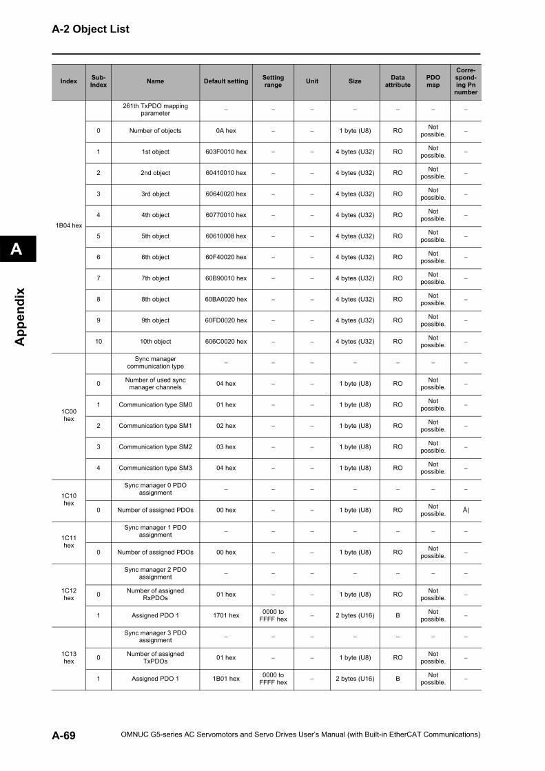
A-2 Object List
A
App
endi
x
1B04 hex
261th TxPDO mapping parameter − − − − − − −
0 Number of objects 0A hex − − 1 byte (U8) RO Not possible. −
1 1st object 603F0010 hex − − 4 bytes (U32) RO Not possible. −
2 2nd object 60410010 hex − − 4 bytes (U32) RO Not possible. −
3 3rd object 60640020 hex − − 4 bytes (U32) RO Not possible. −
4 4th object 60770010 hex − − 4 bytes (U32) RO Not possible. −
5 5th object 60610008 hex − − 4 bytes (U32) RO Not possible. −
6 6th object 60F40020 hex − − 4 bytes (U32) RO Not possible. −
7 7th object 60B90010 hex − − 4 bytes (U32) RO Not possible. −
8 8th object 60BA0020 hex − − 4 bytes (U32) RO Not possible. −
9 9th object 60FD0020 hex − − 4 bytes (U32) RO Not possible. −
10 10th object 606C0020 hex − − 4 bytes (U32) RO Not possible. −
1C00 hex
Sync manager communication type − − − − − − −
0 Number of used sync manager channels 04 hex − − 1 byte (U8) RO Not
possible. −
1 Communication type SM0 01 hex − − 1 byte (U8) RO Not possible. −
2 Communication type SM1 02 hex − − 1 byte (U8) RO Not possible. −
3 Communication type SM2 03 hex − − 1 byte (U8) RO Not possible. −
4 Communication type SM3 04 hex − − 1 byte (U8) RO Not possible. −
1C10 hex
Sync manager 0 PDO assignment − − − − − − −
0 Number of assigned PDOs 00 hex − − 1 byte (U8) RO Not possible. Å|
1C11 hex
Sync manager 1 PDO assignment − − − − − − −
0 Number of assigned PDOs 00 hex − − 1 byte (U8) RO Not possible. −
1C12 hex
Sync manager 2 PDO assignment − − − − − − −
0 Number of assigned RxPDOs 01 hex − − 1 byte (U8) RO Not
possible. −
1 Assigned PDO 1 1701 hex 0000 to FFFF hex − 2 bytes (U16) B Not
possible. −
1C13 hex
Sync manager 3 PDO assignment − − − − − − −
0 Number of assigned TxPDOs 01 hex − − 1 byte (U8) RO Not
possible. −
1 Assigned PDO 1 1B01 hex 0000 to FFFF hex − 2 bytes (U16) B Not
possible. −
Index Sub-Index Name Default setting Setting
range Unit Size Data attribute
PDO map
Corre-spond-ing Pn
number
A-69 OMNUC G5-series AC Servomotors and Servo Drives User’s Manual (with Built-in EtherCAT Communications)
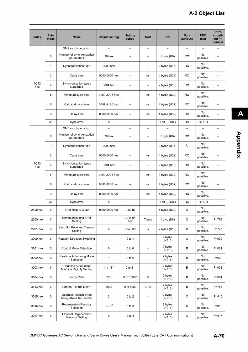
A-2 Object List
A
Appendix
1C32 hex
SM2 synchronization − − − − − − −
0 Number of synchronization parameters 20 hex − − 1 byte (U8) RO Not
possible. −
1 Synchronization type 0002 hex − − 2 bytes (U16) RO Not possible. −
2 Cycle time 0000 0000 hex − ns 4 bytes (U32) RO Not possible. −
4 Synchronization types supported 0004 hex − − 2 bytes (U16) RO Not
possible. −
5 Minimum cycle time 0000 32C8 hex − ns 4 bytes (U32) RO Not possible. −
6 Calc and copy time 0007 A120 hex − ns 4 bytes (U32) RO Not possible. −
9 Delay time 0000 0000 hex − ns 4 bytes (U32) RO Not possible. −
32 Sync error 0 − − 1 bit (BOOL) RO TxPDO −
1C33 hex
SM3 synchronization − − − − − − −
0 Number of synchronization parameters 20 hex − − 1 byte (U8) RO Not
possible. −
1 Synchronization type 0002 hex − − 2 bytes (U16) Å| Not possible. −
2 Cycle time 0000 0000 hex − ns 4 bytes (U32) RO Not possible. −
4 Synchronization types supported 0004 hex − − 2 bytes (U16) RO Not
possible. −
5 Minimum cycle time 0000 32C8 hex − ns 4 bytes (U32) RO Not possible. −
6 Calc and copy time 0006 06F8 hex − ns 4 bytes (U32) RO Not possible. −
9 Delay time 0000 0000 hex − ns 4 bytes (U32) RO Not possible. −
32 Sync error 0 − − 1 bit (BOOL) RO TxPDO −
2100 hex 0 Error History Clear 0000 0000 hex 0 to 15 − 4 bytes (U32) A Not possible. −
2200 hex 0 Communications Error Setting 1 00 to 0F
hex Times 1 byte (U8) C Not possible. Pn776
2201 hex 0 Sync Not Received Timeout Setting 0 0 to 600 s 2 bytes (U16) C Not
possible. Pn777
3000 hex 0 Rotation Direction Switching 1 0 to 1 − 2 bytes (INT16) C Not
possible. Pn000
3001 hex 0 Control Mode Selection 0 0 to 6 − 2 bytes (INT16) R Not
possible. Pn001
3002 hex 0 Realtime Autotuning Mode Selection 1 0 to 6 − 2 bytes
(INT16) B Not possible. Pn002
3003 hex 0 Realtime Autotuning Machine Rigidity Setting 11 / 13*1 0 to 31 − 2 bytes
(INT16) B Not possible. Pn003
3004 hex 0 Inertia Ratio 250 0 to 10000 % 2 bytes (INT16) B Not
possible. Pn004
3013 hex 0 External Torque Limit 1 5000 0 to 5000 0.1% 2 bytes (INT16) B Not
possible. Pn753
3015 hex 0 Operation Switch when Using Absolute Encoder 2 0 to 2 − 2 bytes
(INT16) C Not possible. Pn015
3016 hex 0 Regeneration Resistor Selection 0 / 3*2 0 to 3 − 2 bytes
(INT16) C Not possible. Pn016
3017 hex 0 External Regeneration Resistor Setting 0 0 to 4 − 2 bytes
(INT16) C Not possible. Pn017
Index Sub-Index Name Default setting Setting
range Unit Size Data attribute
PDO map
Corre-spond-ing Pn
number
A-70OMNUC G5-series AC Servomotors and Servo Drives User’s Manual (with Built-in EtherCAT Communications)
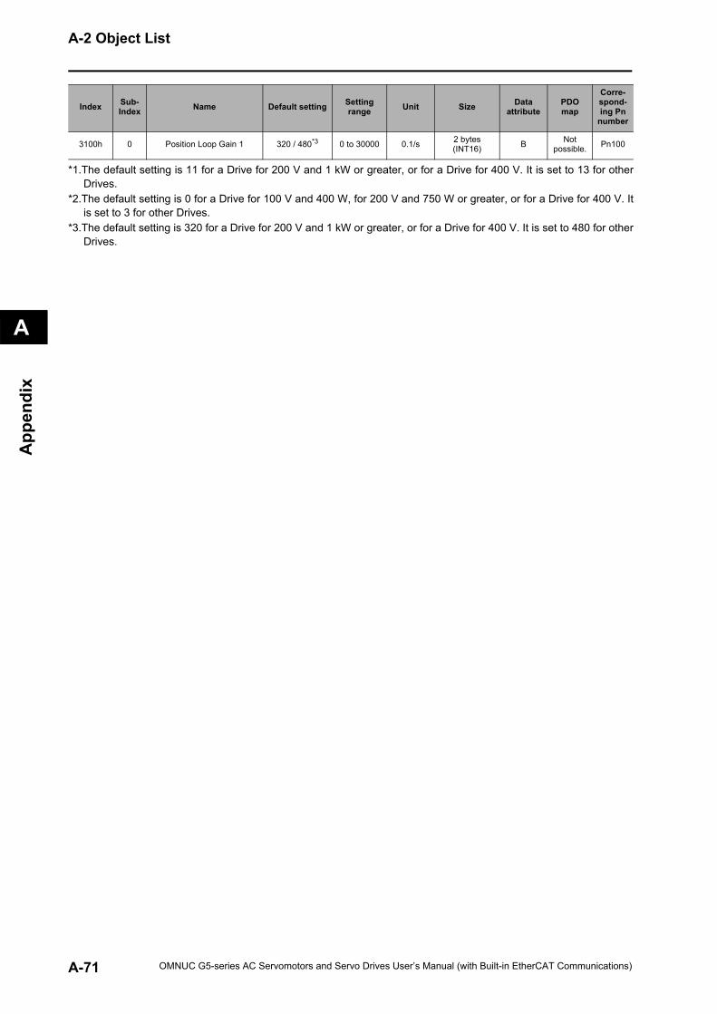
A-2 Object List
A
App
endi
x
3100h 0 Position Loop Gain 1 320 / 480*3 0 to 30000 0.1/s 2 bytes (INT16) B Not
possible. Pn100
*1.The default setting is 11 for a Drive for 200 V and 1 kW or greater, or for a Drive for 400 V. It is set to 13 for otherDrives.
*2.The default setting is 0 for a Drive for 100 V and 400 W, for 200 V and 750 W or greater, or for a Drive for 400 V. Itis set to 3 for other Drives.
*3.The default setting is 320 for a Drive for 200 V and 1 kW or greater, or for a Drive for 400 V. It is set to 480 for otherDrives.
Index Sub-Index Name Default setting Setting
range Unit Size Data attribute
PDO map
Corre-spond-ing Pn
number
A-71 OMNUC G5-series AC Servomotors and Servo Drives User’s Manual (with Built-in EtherCAT Communications)
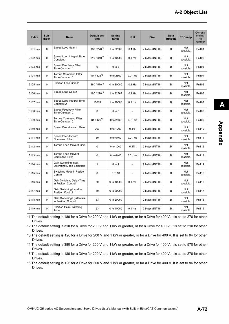
A-2 Object List
A
Appendix
Index Sub-Index Name Default set-
tingSetting range Unit Size Data
attribute PDO mapCorresponding
Pn number
3101 hex 0 Speed Loop Gain 1 180 / 270*1
*1.The default setting is 180 for a Drive for 200 V and 1 kW or greater, or for a Drive for 400 V. It is set to 270 for otherDrives.
1 to 32767 0.1 Hz 2 bytes (INT16) B Not possible. Pn101
3102 hex 0 Speed Loop Integral Time Constant 1 210 / 310*2
*2.The default setting is 310 for a Drive for 200 V and 1 kW or greater, or for a Drive for 400 V. It is set to 210 for otherDrives.
1 to 10000 0.1 ms 2 bytes (INT16) B Not possible. Pn102
3103 hex 0 Speed Feedback Filter Time Constant 1 0 0 to 5 − 2 bytes (INT16) B Not
possible. Pn103
3104 hex 0 Torque Command Filter Time Constant 1 84 / 126*3
*3.The default setting is 126 for a Drive for 200 V and 1 kW or greater, or for a Drive for 400 V. It is set to 84 for otherDrives.
0 to 2500 0.01 ms 2 bytes (INT16) B Not possible. Pn104
3105 hex 0 Position Loop Gain 2 380 / 570*4
*4.The default setting is 380 for a Drive for 200 V and 1 kW or greater, or for a Drive for 400 V. It is set to 570 for otherDrives.
0 to 30000 0.1 Hz 2 bytes (INT16) B Not possible. Pn105
3106 hex 0 Speed Loop Gain 2 180 / 270*5
*5.The default setting is 180 for a Drive for 200 V and 1 kW or greater, or for a Drive for 400 V. It is set to 270 for otherDrives.
1 to 32767 0.1 Hz 2 bytes (INT16) B Not possible. Pn106
3107 hex 0 Speed Loop Integral Time Constant 2 10000 1 to 10000 0.1 ms 2 bytes (INT16) B Not
possible. Pn107
3108 hex 0 Speed Feedback Filter Time Constant 2 0 0 to 5 − 2 bytes (INT16) B Not
possible. Pn108
3109 hex 0 Torque Command Filter Time Constant 2 84 / 126*6
*6.The default setting is 126 for a Drive for 200 V and 1 kW or greater, or for a Drive for 400 V. It is set to 84 for otherDrives.
0 to 2500 0.01 ms 2 bytes (INT16) B Not possible. Pn109
3110 hex 0 Speed Feed-forward Gain 300 0 to 1000 0.1% 2 bytes (INT16) B Not possible. Pn110
3111 hex 0 Speed Feed-forward Command Filter 50 0 to 6400 0.01 ms 2 bytes (INT16) B Not
possible. Pn111
3112 hex 0 Torque Feed-forward Gain 0 0 to 1000 0.1% 2 bytes (INT16) B Not possible. Pn112
3113 hex 0 Torque Feed-forward Command Filter 0 0 to 6400 0.01 ms 2 bytes (INT16) B Not
possible. Pn113
3114 hex 0 Gain Switching Input Operating Mode Selection 1 0 to 1 − 2 bytes (INT16) B Not
possible. Pn114
3115 hex 0 Switching Mode in Position Control 0 0 to 10 − 2 bytes (INT16) B Not
possible. Pn115
3116 hex 0 Gain Switching Delay Time in Position Control 50 0 to 10000 0.1 ms 2 bytes (INT16) B Not
possible. Pn116
3117 hex 0 Gain Switching Level in Position Control 50 0 to 20000 − 2 bytes (INT16) B Not
possible. Pn117
3118 hex 0 Gain Switching Hysteresis in Position Control 33 0 to 20000 − 2 bytes (INT16) B Not
possible. Pn118
3119 hex 0 Position Gain Switching Time 33 0 to 10000 0.1 ms 2 bytes (INT16) B Not
possible. Pn119
A-72OMNUC G5-series AC Servomotors and Servo Drives User’s Manual (with Built-in EtherCAT Communications)
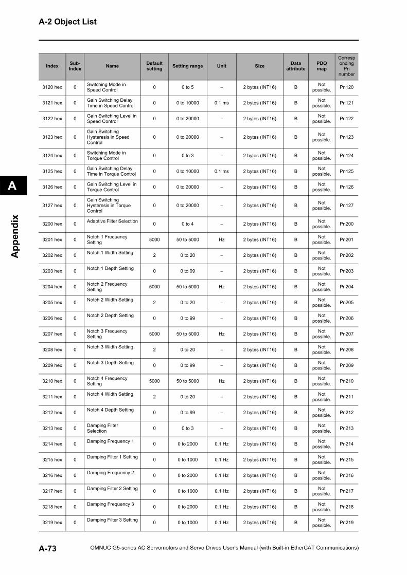
A-2 Object List
A
App
endi
x
Index Sub-Index Name Default
setting Setting range Unit Size Data attribute
PDO map
Corresponding
Pn number
3120 hex 0 Switching Mode in Speed Control 0 0 to 5 − 2 bytes (INT16) B Not
possible. Pn120
3121 hex 0 Gain Switching Delay Time in Speed Control 0 0 to 10000 0.1 ms 2 bytes (INT16) B Not
possible. Pn121
3122 hex 0 Gain Switching Level in Speed Control 0 0 to 20000 − 2 bytes (INT16) B Not
possible. Pn122
3123 hex 0Gain Switching Hysteresis in Speed Control
0 0 to 20000 − 2 bytes (INT16) B Not possible. Pn123
3124 hex 0 Switching Mode in Torque Control 0 0 to 3 − 2 bytes (INT16) B Not
possible. Pn124
3125 hex 0 Gain Switching Delay Time in Torque Control 0 0 to 10000 0.1 ms 2 bytes (INT16) B Not
possible. Pn125
3126 hex 0 Gain Switching Level in Torque Control 0 0 to 20000 − 2 bytes (INT16) B Not
possible. Pn126
3127 hex 0Gain Switching Hysteresis in Torque Control
0 0 to 20000 − 2 bytes (INT16) B Not possible. Pn127
3200 hex 0 Adaptive Filter Selection 0 0 to 4 − 2 bytes (INT16) B Not possible. Pn200
3201 hex 0 Notch 1 Frequency Setting 5000 50 to 5000 Hz 2 bytes (INT16) B Not
possible. Pn201
3202 hex 0 Notch 1 Width Setting 2 0 to 20 − 2 bytes (INT16) B Not possible. Pn202
3203 hex 0 Notch 1 Depth Setting 0 0 to 99 − 2 bytes (INT16) B Not possible. Pn203
3204 hex 0 Notch 2 Frequency Setting 5000 50 to 5000 Hz 2 bytes (INT16) B Not
possible. Pn204
3205 hex 0 Notch 2 Width Setting 2 0 to 20 − 2 bytes (INT16) B Not possible. Pn205
3206 hex 0 Notch 2 Depth Setting 0 0 to 99 − 2 bytes (INT16) B Not possible. Pn206
3207 hex 0 Notch 3 Frequency Setting 5000 50 to 5000 Hz 2 bytes (INT16) B Not
possible. Pn207
3208 hex 0 Notch 3 Width Setting 2 0 to 20 − 2 bytes (INT16) B Not possible. Pn208
3209 hex 0 Notch 3 Depth Setting 0 0 to 99 − 2 bytes (INT16) B Not possible. Pn209
3210 hex 0 Notch 4 Frequency Setting 5000 50 to 5000 Hz 2 bytes (INT16) B Not
possible. Pn210
3211 hex 0 Notch 4 Width Setting 2 0 to 20 − 2 bytes (INT16) B Not possible. Pn211
3212 hex 0 Notch 4 Depth Setting 0 0 to 99 − 2 bytes (INT16) B Not possible. Pn212
3213 hex 0 Damping Filter Selection 0 0 to 3 − 2 bytes (INT16) B Not
possible. Pn213
3214 hex 0 Damping Frequency 1 0 0 to 2000 0.1 Hz 2 bytes (INT16) B Not possible. Pn214
3215 hex 0 Damping Filter 1 Setting 0 0 to 1000 0.1 Hz 2 bytes (INT16) B Not possible. Pn215
3216 hex 0 Damping Frequency 2 0 0 to 2000 0.1 Hz 2 bytes (INT16) B Not possible. Pn216
3217 hex 0 Damping Filter 2 Setting 0 0 to 1000 0.1 Hz 2 bytes (INT16) B Not possible. Pn217
3218 hex 0 Damping Frequency 3 0 0 to 2000 0.1 Hz 2 bytes (INT16) B Not possible. Pn218
3219 hex 0 Damping Filter 3 Setting 0 0 to 1000 0.1 Hz 2 bytes (INT16) B Not possible. Pn219
A-73 OMNUC G5-series AC Servomotors and Servo Drives User’s Manual (with Built-in EtherCAT Communications)
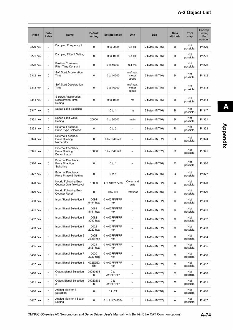
A-2 Object List
A
Appendix
3220 hex 0 Damping Frequency 4 0 0 to 2000 0.1 Hz 2 bytes (INT16) B Not possible. Pn220
3221 hex 0 Damping Filter 4 Setting 0 0 to 1000 0.1 Hz 2 bytes (INT16) B Not possible. Pn221
3222 hex 0 Position Command Filter Time Constant 0 0 to 10000 0.1 ms 2 bytes (INT16) B Not
possible. Pn222
3312 hex 0Soft Start Acceleration Time 0 0 to 10000
ms/max. motor speed
2 bytes (INT16) B Not possible. Pn312
3313 hex 0Soft Start Deceleration Time 0 0 to 10000
ms/max. motor speed
2 bytes (INT16) B Not possible. Pn313
3314 hex 0S-curve Acceleration/Deceleration Time Setting
0 0 to 1000 ms 2 bytes (INT16) B Not possible. Pn314
3317 hex 0 Speed Limit Selection 1 0 to 1 ms 2 bytes (INT16) B Not possible. Pn317
3321 hex 0 Speed Limit Value Setting 20000 0 to 20000 r/min 2 bytes (INT16) B Not
possible. Pn321
3323 hex 0 External Feedback Pulse Type Selection 0 0 to 2 − 2 bytes (INT16) R Not
possible. Pn323
3324 hex 0External Feedback Pulse Dividing Numerator
0 0 to 1048576 − 4 bytes (INT32) R Not possible. Pn324
3325 hex 0External Feedback Pulse Dividing Denominator
10000 1 to 1048576 − 4 bytes (INT32) R Not possible. Pn325
3326 hex 0External Feedback Pulse Direction Switching
0 0 to 1 − 2 bytes (INT16) R Not possible. Pn326
3327 hex 0 External Feedback Pulse Phase-Z Setting 0 0 to 1 − 2 bytes (INT16) R Not
possible. Pn327
3328 hex 0 Hybrid Following Error Counter Overflow Level 16000 1 to 134217728 Command
units 4 bytes (INT32) C Not possible. Pn328
3329 hex 0 Hybrid Following Error Counter Reset 0 0 to 100 Rotations 2 bytes (INT16) C Not
possible. Pn329
3400 hex 0 Input Signal Selection 1 0094 9494 hex
0 to 00FF FFFF hex − 4 bytes (INT32) C Not
possible. Pn400
3401 hex 0 Input Signal Selection 2 0081 8181 hex
0 to 00FF FFFF hex − 4 bytes (INT32) C Not
possible. Pn401
3402 hex 0 Input Signal Selection 3 0082 8282 hex
0 to 00FF FFFF hex − 4 bytes (INT32) C Not
possible. Pn402
3403 hex 0 Input Signal Selection 4 0022 2222 hex
0 to 00FF FFFF hex − 4 bytes (INT32) C Not
possible. Pn403
3404 hex 0 Input Signal Selection 5 002B 2B2B hex
0 to 00FF FFFF hex − 4 bytes (INT32) C Not
possible. Pn404
3405 hex 0 Input Signal Selection 6 0021 2121 hex
0 to 00FF FFFF hex − 4 bytes (INT32) C Not
possible. Pn405
3406 hex 0 Input Signal Selection 7 0020 2020 hex
0 to 00FF FFFF hex − 4 bytes (INT32) C Not
possible. Pn406
3407 hex 0 Input Signal Selection 8 002E2E2Eh
0 to 00FF FFFF hex − 4 bytes (INT32) C Not
possible. Pn407
3410 hex 0 Output Signal Selection 1
00030303h
0 to 00FFFFFFh − 4 bytes (INT32) C Not
possible. Pn410
3411 hex 0 Output Signal Selection 2
00020202h
0 to 00FFFFFFh − 4 bytes (INT32) C Not
possible. Pn411
3416 hex 0 Analog Monitor 1 Selection 0 0 to 21 *1 2 bytes (INT16) A Not
possible. Pn416
3417 hex 0 Analog Monitor 1 Scale Setting 0 0 to 214748364 *2 4 bytes (INT32) A Not
possible. Pn417
Index Sub-Index Name Default
setting Setting range Unit Size Data attribute
PDO map
Corresponding
Pn number
A-74OMNUC G5-series AC Servomotors and Servo Drives User’s Manual (with Built-in EtherCAT Communications)
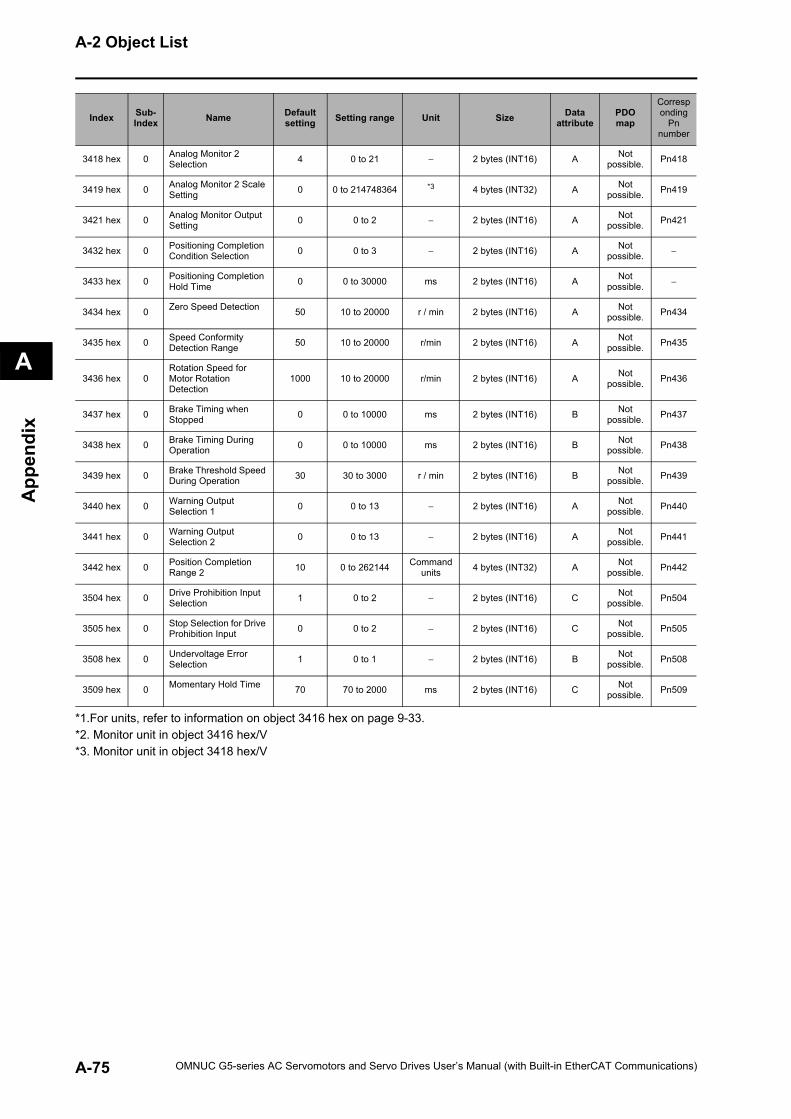
A-2 Object List
A
App
endi
x
3418 hex 0 Analog Monitor 2 Selection 4 0 to 21 − 2 bytes (INT16) A Not
possible. Pn418
3419 hex 0 Analog Monitor 2 Scale Setting 0 0 to 214748364 *3 4 bytes (INT32) A Not
possible. Pn419
3421 hex 0 Analog Monitor Output Setting 0 0 to 2 − 2 bytes (INT16) A Not
possible. Pn421
3432 hex 0 Positioning Completion Condition Selection 0 0 to 3 − 2 bytes (INT16) A Not
possible. −
3433 hex 0 Positioning Completion Hold Time 0 0 to 30000 ms 2 bytes (INT16) A Not
possible. −
3434 hex 0 Zero Speed Detection 50 10 to 20000 r / min 2 bytes (INT16) A Not possible. Pn434
3435 hex 0 Speed Conformity Detection Range 50 10 to 20000 r/min 2 bytes (INT16) A Not
possible. Pn435
3436 hex 0Rotation Speed for Motor Rotation Detection
1000 10 to 20000 r/min 2 bytes (INT16) A Not possible. Pn436
3437 hex 0 Brake Timing when Stopped 0 0 to 10000 ms 2 bytes (INT16) B Not
possible. Pn437
3438 hex 0 Brake Timing During Operation 0 0 to 10000 ms 2 bytes (INT16) B Not
possible. Pn438
3439 hex 0 Brake Threshold Speed During Operation 30 30 to 3000 r / min 2 bytes (INT16) B Not
possible. Pn439
3440 hex 0 Warning Output Selection 1 0 0 to 13 − 2 bytes (INT16) A Not
possible. Pn440
3441 hex 0 Warning Output Selection 2 0 0 to 13 − 2 bytes (INT16) A Not
possible. Pn441
3442 hex 0 Position Completion Range 2 10 0 to 262144 Command
units 4 bytes (INT32) A Not possible. Pn442
3504 hex 0 Drive Prohibition Input Selection 1 0 to 2 − 2 bytes (INT16) C Not
possible. Pn504
3505 hex 0 Stop Selection for Drive Prohibition Input 0 0 to 2 − 2 bytes (INT16) C Not
possible. Pn505
3508 hex 0 Undervoltage Error Selection 1 0 to 1 − 2 bytes (INT16) B Not
possible. Pn508
3509 hex 0 Momentary Hold Time 70 70 to 2000 ms 2 bytes (INT16) C Not possible. Pn509
*1.For units, refer to information on object 3416 hex on page 9-33. *2. Monitor unit in object 3416 hex/V*3. Monitor unit in object 3418 hex/V
Index Sub-Index Name Default
setting Setting range Unit Size Data attribute
PDO map
Corresponding
Pn number
A-75 OMNUC G5-series AC Servomotors and Servo Drives User’s Manual (with Built-in EtherCAT Communications)
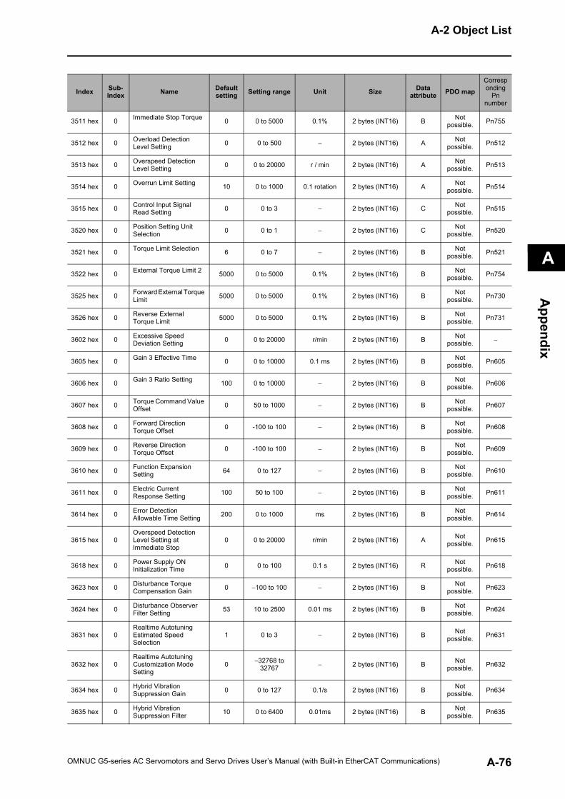
A-2 Object List
A
Appendix
Index Sub-Index Name Default
setting Setting range Unit Size Data attribute PDO map
Corresponding
Pn number
3511 hex 0 Immediate Stop Torque 0 0 to 5000 0.1% 2 bytes (INT16) B Not possible. Pn755
3512 hex 0 Overload Detection Level Setting 0 0 to 500 − 2 bytes (INT16) A Not
possible. Pn512
3513 hex 0 Overspeed Detection Level Setting 0 0 to 20000 r / min 2 bytes (INT16) A Not
possible. Pn513
3514 hex 0 Overrun Limit Setting 10 0 to 1000 0.1 rotation 2 bytes (INT16) A Not possible. Pn514
3515 hex 0 Control Input Signal Read Setting 0 0 to 3 − 2 bytes (INT16) C Not
possible. Pn515
3520 hex 0 Position Setting Unit Selection 0 0 to 1 − 2 bytes (INT16) C Not
possible. Pn520
3521 hex 0 Torque Limit Selection 6 0 to 7 − 2 bytes (INT16) B Not possible. Pn521
3522 hex 0 External Torque Limit 2 5000 0 to 5000 0.1% 2 bytes (INT16) B Not possible. Pn754
3525 hex 0 Forward External Torque Limit 5000 0 to 5000 0.1% 2 bytes (INT16) B Not
possible. Pn730
3526 hex 0 Reverse External Torque Limit 5000 0 to 5000 0.1% 2 bytes (INT16) B Not
possible. Pn731
3602 hex 0 Excessive Speed Deviation Setting 0 0 to 20000 r/min 2 bytes (INT16) B Not
possible. −
3605 hex 0 Gain 3 Effective Time 0 0 to 10000 0.1 ms 2 bytes (INT16) B Not possible. Pn605
3606 hex 0 Gain 3 Ratio Setting 100 0 to 10000 − 2 bytes (INT16) B Not possible. Pn606
3607 hex 0 Torque Command Value Offset 0 50 to 1000 − 2 bytes (INT16) B Not
possible. Pn607
3608 hex 0 Forward Direction Torque Offset 0 -100 to 100 − 2 bytes (INT16) B Not
possible. Pn608
3609 hex 0 Reverse Direction Torque Offset 0 -100 to 100 − 2 bytes (INT16) B Not
possible. Pn609
3610 hex 0 Function Expansion Setting 64 0 to 127 − 2 bytes (INT16) B Not
possible. Pn610
3611 hex 0 Electric Current Response Setting 100 50 to 100 − 2 bytes (INT16) B Not
possible. Pn611
3614 hex 0 Error Detection Allowable Time Setting 200 0 to 1000 ms 2 bytes (INT16) B Not
possible. Pn614
3615 hex 0Overspeed Detection Level Setting at Immediate Stop
0 0 to 20000 r/min 2 bytes (INT16) A Not possible. Pn615
3618 hex 0 Power Supply ON Initialization Time 0 0 to 100 0.1 s 2 bytes (INT16) R Not
possible. Pn618
3623 hex 0 Disturbance Torque Compensation Gain 0 −100 to 100 − 2 bytes (INT16) B Not
possible. Pn623
3624 hex 0 Disturbance Observer Filter Setting 53 10 to 2500 0.01 ms 2 bytes (INT16) B Not
possible. Pn624
3631 hex 0Realtime Autotuning Estimated Speed Selection
1 0 to 3 − 2 bytes (INT16) B Not possible. Pn631
3632 hex 0Realtime Autotuning Customization Mode Setting
0 −32768 to 32767 − 2 bytes (INT16) B Not
possible. Pn632
3634 hex 0 Hybrid Vibration Suppression Gain 0 0 to 127 0.1/s 2 bytes (INT16) B Not
possible. Pn634
3635 hex 0 Hybrid Vibration Suppression Filter 10 0 to 6400 0.01ms 2 bytes (INT16) B Not
possible. Pn635
A-76OMNUC G5-series AC Servomotors and Servo Drives User’s Manual (with Built-in EtherCAT Communications)
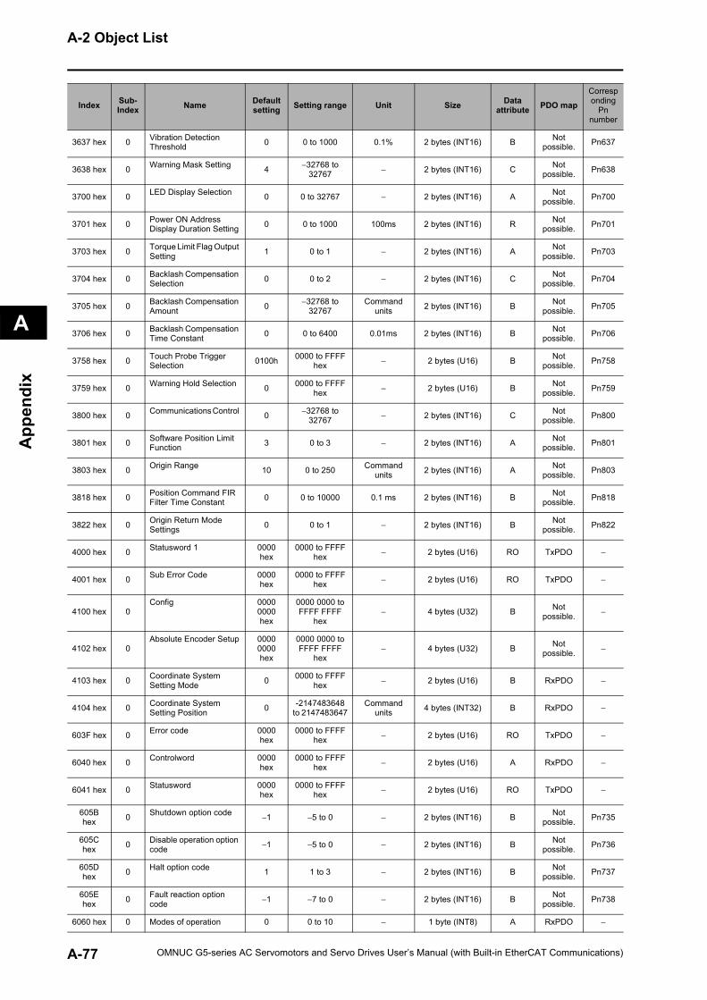
A-2 Object List
A
App
endi
x
3637 hex 0 Vibration Detection Threshold 0 0 to 1000 0.1% 2 bytes (INT16) B Not
possible. Pn637
3638 hex 0 Warning Mask Setting 4 −32768 to 32767 − 2 bytes (INT16) C Not
possible. Pn638
3700 hex 0 LED Display Selection 0 0 to 32767 − 2 bytes (INT16) A Not possible. Pn700
3701 hex 0 Power ON Address Display Duration Setting 0 0 to 1000 100ms 2 bytes (INT16) R Not
possible. Pn701
3703 hex 0 Torque Limit Flag Output Setting 1 0 to 1 − 2 bytes (INT16) A Not
possible. Pn703
3704 hex 0 Backlash Compensation Selection 0 0 to 2 − 2 bytes (INT16) C Not
possible. Pn704
3705 hex 0 Backlash Compensation Amount 0 −32768 to
32767Command
units 2 bytes (INT16) B Not possible. Pn705
3706 hex 0 Backlash Compensation Time Constant 0 0 to 6400 0.01ms 2 bytes (INT16) B Not
possible. Pn706
3758 hex 0 Touch Probe Trigger Selection 0100h 0000 to FFFF
hex − 2 bytes (U16) B Not possible. Pn758
3759 hex 0 Warning Hold Selection 0 0000 to FFFF hex − 2 bytes (U16) B Not
possible. Pn759
3800 hex 0 Communications Control 0 −32768 to 32767 − 2 bytes (INT16) C Not
possible. Pn800
3801 hex 0 Software Position Limit Function 3 0 to 3 − 2 bytes (INT16) A Not
possible. Pn801
3803 hex 0 Origin Range 10 0 to 250 Command units 2 bytes (INT16) A Not
possible. Pn803
3818 hex 0 Position Command FIR Filter Time Constant 0 0 to 10000 0.1 ms 2 bytes (INT16) B Not
possible. Pn818
3822 hex 0 Origin Return Mode Settings 0 0 to 1 − 2 bytes (INT16) B Not
possible. Pn822
4000 hex 0 Statusword 1 0000 hex
0000 to FFFF hex − 2 bytes (U16) RO TxPDO −
4001 hex 0 Sub Error Code 0000 hex
0000 to FFFF hex − 2 bytes (U16) RO TxPDO −
4100 hex 0Config 0000
0000 hex
0000 0000 to FFFF FFFF
hex− 4 bytes (U32) B Not
possible. −
4102 hex 0Absolute Encoder Setup 0000
0000 hex
0000 0000 to FFFF FFFF
hex− 4 bytes (U32) B Not
possible. −
4103 hex 0 Coordinate System Setting Mode 0 0000 to FFFF
hex − 2 bytes (U16) B RxPDO −
4104 hex 0 Coordinate System Setting Position 0 -2147483648
to 2147483647Command
units 4 bytes (INT32) B RxPDO −
603F hex 0 Error code 0000 hex
0000 to FFFF hex − 2 bytes (U16) RO TxPDO −
6040 hex 0 Controlword 0000 hex
0000 to FFFF hex − 2 bytes (U16) A RxPDO −
6041 hex 0 Statusword 0000 hex
0000 to FFFF hex − 2 bytes (U16) RO TxPDO −
605B hex 0 Shutdown option code −1 −5 to 0 − 2 bytes (INT16) B Not
possible. Pn735
605C hex 0 Disable operation option
code −1 −5 to 0 − 2 bytes (INT16) B Not possible. Pn736
605D hex 0 Halt option code 1 1 to 3 − 2 bytes (INT16) B Not
possible. Pn737
605E hex 0 Fault reaction option
code −1 −7 to 0 − 2 bytes (INT16) B Not possible. Pn738
6060 hex 0 Modes of operation 0 0 to 10 − 1 byte (INT8) A RxPDO −
Index Sub-Index Name Default
setting Setting range Unit Size Data attribute PDO map
Corresponding
Pn number
A-77 OMNUC G5-series AC Servomotors and Servo Drives User’s Manual (with Built-in EtherCAT Communications)
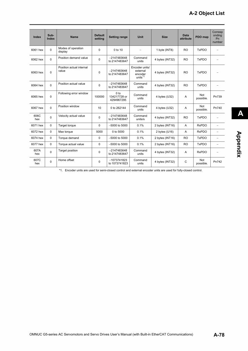
A-2 Object List
A
Appendix
6061 hex 0 Modes of operation display 0 0 to 10 − 1 byte (INT8) RO TxPDO −
6062 hex 0 Position demand value 0 −2147483648 to 2147483647
Command units 4 bytes (INT32) RO TxPDO −
6063 hex 0
Position actual internal value 0 −2147483648
to 2147483647
Encoder units/external encoder units*1
4 bytes (INT32) RO TxPDO −
6064 hex 0 Position actual value 0 −2147483648 to 2147483647
Command units 4 bytes (INT32) RO TxPDO −
6065 hex 0Following error window
1000000 to
134217728 or 4294967295
Command units 4 bytes (U32) A Not
possible. Pn739
6067 hex 0 Position window 10 0 to 262144 Command units 4 bytes (U32) A Not
possible. Pn740
606C hex 0 Velocity actual value 0 −2147483648
to 2147483647Command
units/s 4 bytes (INT32) RO TxPDO −
6071 hex 0 Target torque 0 −5000 to 5000 0.1% 2 bytes (INT16) A RxPDO −
6072 hex 0 Max torque 5000 0 to 5000 0.1% 2 bytes (U16) A RxPDO −
6074 hex 0 Torque demand 0 −5000 to 5000 0.1% 2 bytes (INT16) RO TxPDO −
6077 hex 0 Torque actual value 0 −5000 to 5000 0.1% 2 bytes (INT16) RO TxPDO −
607A hex 0 Target position 0 −2147483648
to 2147483647Command
units 4 bytes (INT32) A RxPDO −
607C hex 0 Home offset 0 −1073741823
to 1073741823Command
units 4 bytes (INT32) C Not possible. Pn742
*1. Encoder units are used for semi-closed control and external encoder units are used for fully-closed control.
Index Sub-Index Name Default
setting Setting range Unit Size Data attribute PDO map
Corresponding
Pn number
A-78OMNUC G5-series AC Servomotors and Servo Drives User’s Manual (with Built-in EtherCAT Communications)
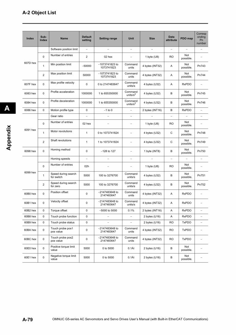
A-2 Object List
A
App
endi
x
Index Sub-Index Name Default
setting Setting range Unit Size Data attribute PDO map
Corresponding
Pn number
607D hex
Software position limit − − − − − − −
0 Number of entries 2 02 hex − 1 byte (U8) RO Not possible. −
1 Min position limit −50000 −1073741823 to 1073741823
Command units 4 bytes (INT32) A Not
possible. Pn743
2 Max position limit 50000 −1073741823 to 1073741823
Command units 4 bytes (INT32) A Not
possible. Pn744
607F hex 0 Max profile velocity 0 0 to 2147483647 Command units/s 4 bytes (U32) A RxPDO −
6083 hex 0 Profile acceleration 1000000 1 to 655350000 Command units/s2 4 bytes (U32) B Not
possible. Pn745
6084 hex 0 Profile deceleration 1000000 1 to 655350000 Command units/s2 4 bytes (U32) B Not
possible. Pn746
6086 hex 0 Motion profile type 0 −1 to 0 − 2 bytes (INT16) B RxPDO −
6091 hex
Gear ratio − − − − − − −
0 Number of entries 02 hex − − 1 byte (U8) RO Not possible. −
1 Motor revolutions 1 0 to 1073741824 − 4 bytes (U32) C Not possible. Pn748
2 Shaft revolutions 1 1 to 1073741824 − 4 bytes (U32) C Not possible. Pn749
6098 hex 0 Homing method 0 −128 to 127 − 1 byte (INT8) B Not possible. Pn750
6099 hex
Homing speeds − − − − − − −
0 Number of entries 02h − − 1 byte (U8) RO Not possible. −
1 Speed during search for switch 5000 100 to 3276700 Command
units/s 4 bytes (U32) B Not possible. Pn751
2 Speed during search for zero 5000 100 to 3276700 Command
units/s 4 bytes (U32) B Not possible. Pn752
60B0 hex 0 Position offset 0 −2147483648 to 2147483647
Command units 4 bytes (INT32) A RxPDO −
60B1 hex 0 Velocity offset 0 −2147483648 to 2147483647
Command units/s 4 bytes (INT32) A RxPDO −
60B2 hex 0 Torque offset 0 −5000 to 5000 0.1% 2 bytes (INT16) A RxPDO −
60B8 hex 0 Touch probe function 0 − − 2 bytes (U16) A RxPDO −
60B9 hex 0 Touch probe status 0 − − 2 bytes (U16) RO TxPDO −
60BA hex 0 Touch probe pos1 pos value 0 −2147483648 to
2147483647Command
units 4 bytes (INT32) RO TxPDO −
60BC hex 0 Touch probe pos2 pos value 0 −2147483648 to
2147483647Command
units 4 bytes (INT32) RO TxPDO −
60E0 hex 0 Positive torque limit value 5000 0 to 5000 0.1Åì 2 bytes (U16) B Not
possible. −
60E1 hex 0 Negative torque limit value 5000 0 to 5000 0.1Åì 2 bytes (U16) B Not
possible. −
A-79 OMNUC G5-series AC Servomotors and Servo Drives User’s Manual (with Built-in EtherCAT Communications)
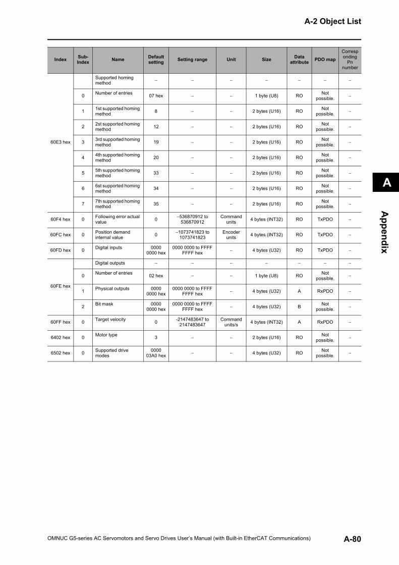
A-2 Object List
A
Appendix
60E3 hex
Supported homing method − − − − − − −
0 Number of entries 07 hex − − 1 byte (U8) RO Not possible. −
1 1st supported homing method 8 − − 2 bytes (U16) RO Not
possible. −
2 2st supported homing method 12 − − 2 bytes (U16) RO Not
possible. −
3 3rd supported homing method 19 − − 2 bytes (U16) RO Not
possible. −
4 4th supported homing method 20 − − 2 bytes (U16) RO Not
possible. −
5 5th supported homing method 33 − − 2 bytes (U16) RO Not
possible. −
6 6st supported homing method 34 − − 2 bytes (U16) RO Not
possible. −
7 7th supported homing method 35 − − 2 bytes (U16) RO Not
possible. −
60F4 hex 0 Following error actual value 0 −536870912 to
536870912Command
units 4 bytes (INT32) RO TxPDO −
60FC hex 0 Position demand internal value 0 −1073741823 to
1073741823Encoder
units 4 bytes (INT32) RO TxPDO −
60FD hex 0 Digital inputs 0000 0000 hex
0000 0000 to FFFF FFFF hex − 4 bytes (U32) RO TxPDO −
60FE hex
Digital outputs − − − − − − −
0 Number of entries 02 hex − − 1 byte (U8) RO Not possible. −
1 Physical outputs 0000 0000 hex
0000 0000 to FFFF FFFF hex − 4 bytes (U32) A RxPDO −
2 Bit mask 0000 0000 hex
0000 0000 to FFFF FFFF hex − 4 bytes (U32) B Not
possible. −
60FF hex 0 Target velocity 0 -2147483647 to 2147483647
Command units/s 4 bytes (INT32) A RxPDO −
6402 hex 0 Motor type 3 − − 2 bytes (U16) RO Not possible. −
6502 hex 0 Supported drive modes
0000 03A0 hex − − 4 bytes (U32) RO Not
possible. −
Index Sub-Index Name Default
setting Setting range Unit Size Data attribute PDO map
Corresponding
Pn number
A-80OMNUC G5-series AC Servomotors and Servo Drives User’s Manual (with Built-in EtherCAT Communications)
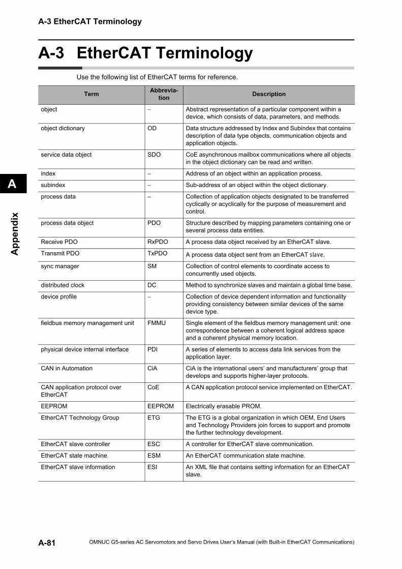
A-3 EtherCAT Terminology
A
App
endi
x
A-3 EtherCAT TerminologyUse the following list of EtherCAT terms for reference.
Term Abbrevia-tion Description
object − Abstract representation of a particular component within a device, which consists of data, parameters, and methods.
object dictionary OD Data structure addressed by Index and Subindex that contains description of data type objects, communication objects and application objects.
service data object SDO CoE asynchronous mailbox communications where all objects in the object dictionary can be read and written.
index − Address of an object within an application process.
subindex − Sub-address of an object within the object dictionary.
process data − Collection of application objects designated to be transferred cyclically or acyclically for the purpose of measurement and control.
process data object PDO Structure described by mapping parameters containing one or several process data entities.
Receive PDO RxPDO A process data object received by an EtherCAT slave.
Transmit PDO TxPDO A process data object sent from an EtherCAT slave.
sync manager SM Collection of control elements to coordinate access to concurrently used objects.
distributed clock DC Method to synchronize slaves and maintain a global time base.
device profile − Collection of device dependent information and functionality providing consistency between similar devices of the same device type.
fieldbus memory management unit FMMU Single element of the fieldbus memory management unit: one correspondence between a coherent logical address space and a coherent physical memory location.
physical device internal interface PDI A series of elements to access data link services from the application layer.
CAN in Automation CiA CiA is the international users’ and manufacturers’ group that develops and supports higher-layer protocols.
CAN application protocol over EtherCAT
CoE A CAN application protocol service implemented on EtherCAT.
EEPROM EEPROM Electrically erasable PROM.
EtherCAT Technology Group ETG The ETG is a global organization in which OEM, End Users and Technology Providers join forces to support and promote the further technology development.
EtherCAT slave controller ESC A controller for EtherCAT slave communication.
EtherCAT state machine ESM An EtherCAT communication state machine.
EtherCAT slave information ESI An XML file that contains setting information for an EtherCAT slave.
A-81 OMNUC G5-series AC Servomotors and Servo Drives User’s Manual (with Built-in EtherCAT Communications)

I
OMNUC G5-series AC Servomotors and Servo Drives User’s Manual (with Built-in EtherCAT Communications)
Index
Index
I
Numerics
1,000-r/min Servomotorsmodel table .................................................. 2-10rotation speed characteristics .......................... 3-61Servo Drives................................................. 2-13
2,000-r/min Servomotorsmodel table .................................................... 2-8rotation speed characteristics .......................... 3-55Servo Drives................................................. 2-12
3,000-r/min Servomotorsmodel table .................................................... 2-6rotation speed characteristics .......................... 3-44Servo Drives................................................. 2-11
7-Segment display............................................. 10-4
A
absolute encoderbackup battery .............................................. 2-20battery cables ............................................... 2-20battery replacement ...................................... 12-35setup........................................................... 10-6specifications................................................ 3-62
Accessories......................................................... 12adaptive filter ................................................... 11-18analog control objects
External Feedback Pulse Direction Switching (3326 hex) ................................................... 9-29External Feedback Pulse Dividing Denominator (3325 hex) ................................................... 9-29External Feedback Pulse Dividing Numerator (3324 hex) ................................................... 9-29External Feedback Pulse Phase-Z Setting (3327 hex) ................................................... 9-30External Feedback Pulse Type Selection (3323 hex) ................................................... 9-27Hybrid Following Error Counter Overflow Level (3328 hex) ................................................... 9-30Hybrid Following Error Counter Reset (3329 hex) 9-30S-curve Acceleration/Deceleration Time Setting (3314 hex) ................................................... 9-26Soft Start Acceleration Time (3312 hex) ............ 9-26Soft Start Deceleration Time (3313 hex) ............ 9-26Speed Limit Selection (3317 hex) ..................... 9-27Speed Limit Value Setting (3321 hex) ............... 9-27
analog monitor .................................................. 11-1Analog Monitor Cable................................. 2-20, 3-79analog monitor connector specifications (CN5) ....... 3-32applicable standards .......................................... 1-15
B
backlash compensation ...................................... 7-11Backup Battery Inputs (BAT) ............................... 3-23basic settings
Control Mode Selection (3001 hex)..................... 9-2External Regeneration Resistor Setting (3017 hex) 9-5External Torque Limit 1 (3013 hex) ..................... 9-4Inertia Ratio (3004 hex) .................................... 9-3Operation Switch when Using Absolute Encoder (3015 hex) ..................................................... 9-4Realtime Autotuning Machine Rigidity Setting (3003 hex) ..................................................... 9-3
Realtime Autotuning Mode Selection (3002 hex)... 9-2Regeneration Resistor Selection (3016 hex) ........ 9-5Rotation Direction Switching (3000 hex) .............. 9-1
Brake Cable Connector ....................................... 3-75brake cables (European flexible cables) ................. 2-15brake cables (global flexible cables) ...................... 2-20brake cables (global non-flexible cables) ................ 2-17brake interlock ................................................... 7-13Brake Interlock Output (BKIR) .............................. 3-25brake power supply ............................................ 4-41
C
CAN application protocol over EtherCAT ................. 5-3clamp core........................................................ 4-42communication objects....................................... A-19
Backup parameter mode (10F0 hex)................. A-24Device type (1000 hex) .................................. A-19Diagnosis history (10F3 hex)........................... A-24Error register (1001 hex) ................................ A-20Identity object (1018 hex) ............................... A-23Manufacturer device name (1008 hex) .............. A-20Manufacturer hardware version (1009 hex) ........ A-20Manufacturer software version (100A hex)......... A-21Restore default parameters (1011 hex) ............. A-22Store parameters (1010 hex)........................... A-21
Completion ....................................................... 9-35Connector-terminal Block .................................... 2-21Connector-terminal Block Cables .......................... 2-21Connector-Terminal Block Conversion Unit ............. 3-82connectors
model list ...................................................... 2-21contactors......................................................... 4-44control cables
model list ...................................................... 2-21control circuit connector specifications (CNC).......... 4-22control circuit connector specifications (CND).......... 3-12control I/O connector specifications ....................... 3-73control I/O signal
connections and external signal processing ........ 3-17connectors.................................................... 3-19control input table........................................... 3-18control output table......................................... 3-18pin arrangement ............................................ 3-19
control input circuits............................................ 3-20control output circuits .......................................... 3-23control output sequence ...................................... 3-24control panel structure......................................... 4-37Cyclic synchronous position mode.......................... 6-1Cyclic synchronous torque mode ........................... 6-7Cyclic synchronous velocity mode .......................... 6-4
D
damping control ............................................... 11-15decelerator
installation conditions....................................... 4-5distributed clock (DC).......................................... 5-10disturbance observer function............................. 11-24
2 OMNUC G5-series AC Servomotors and Servo Drives User’s Manual (with Built-in EtherCAT Communications)
Index
I
E
EC Directives ................................................... 1-15EDM output ........................................................ 8-3EDM output circuit ............................................. 3-35electronic gear function ...................................... 7-18EMC filter specifications ..................................... 3-88emergency messages ........................................ 5-11encoder
specifications................................................ 3-62encoder cable
noise resistance............................................ 4-45encoder cable specifications................................ 3-63encoder cables (European flexible cables) ..... 2-13, 3-63encoder cables (global flexible cables) .................. 2-18encoder cables (global non-flexible cables) ............ 2-15encoder connector specifications (CN2) ................ 3-28encoder connectors ........................................... 3-73Error Clear Attribute Output (ALM-ATB)................. 3-27error list ........................................................... 12-8Error Output (/ALM) ........................................... 3-25EtherCAT........................................................... 1-2
command coding............................................. A-2communications cable.................................... 2-20communications cycle .................................... 5-10communications specifications........................... 3-6Cyclic synchronous position mode...................... 6-1state coding ................................................... A-3state descriptions ............................................ A-2terminology .................................................. A-81
EtherCAT Slave Information file ............................. 5-1EtherCAT State Machine ...................................... 5-4extended objects
Control Input Signal Read Setting (3515 hex) ..... 9-43Drive Prohibition Input Selection (3504 hex) ....... 9-40External Torque Limit 2 (3522 hex)................... 9-45Forward External Torque Limit (3525 hex) ......... 9-45Immediate Stop Torque (3511 hex) .................. 9-42Momentary Hold Time (3509 hex) .................... 9-42Overload Detection Level Setting (3512 hex)...... 9-42Overrun Limit Setting (3514 hex)...................... 9-43Overspeed Detection Level Setting (3513 hex) ... 9-43Position Setting Unit Selection (3520 hex) ......... 9-44Reverse External Torque Limit (3526 hex) ......... 9-45Stop Selection for Drive Prohibition Input (3505 hex) ................................................... 9-41Torque Limit Selection (3521 hex) .................... 9-44Undervoltage Error Selection (3508 hex) ........... 9-42
external device monitor (EDM) output signal ............ 8-3external encoder
connection of external encoder input signals ...... 3-29example of connection ................................... 3-30input signal table ........................................... 3-29
External Encoder Connector................................ 3-80external encoder connector specifications (CN4)..... 3-28External Feedback Pulse Dividing Ratio Setting ...... 6-16External Latch Input Signals (EXT1, EXT2 and EXT3)..................................... 3-22External Regeneration Resistor ........................... 4-52
combining .................................................... 4-55connecting ................................................... 4-53dimensions .................................................. 2-66model list ..................................................... 2-21specifications................................................ 3-86
External Regeneration Resistor connector specifications (CNC)................................... 3-12, 4-18External Regeneration Resistor connector specifications (CND)........................................... 4-22External Torque Limit Input (NCL) ......................... 3-23
F
feed-forward function ........................................ 11-29fixed PDO mapping ............................................. 5-6forward drive prohibition function............................ 7-6Forward Drive Prohibition Input (POT) ................... 3-22Forward External Torque Limit Input (PCL) ............. 3-23friction torque compensation function................... 11-26fully-closed control ............................................. 6-12
supported external encoders ............................ 6-14fully-closed mode adjustment ............................. 11-14
G
gain adjustment ................................................. 11-4gain settings
Gain Switching Delay Time in Position Control (3116 hex) .................................................... 9-13Gain Switching Delay Time in Speed Control (3121 hex) .................................................... 9-16Gain Switching Delay Time in Torque Control (3125 hex) .................................................... 9-18Gain Switching Hysteresis in Position Control (3118 hex) .................................................... 9-14Gain Switching Hysteresis in Speed Control (3123 hex) .................................................... 9-17Gain Switching Hysteresis in Torque Control (3127 hex) .................................................... 9-19Gain Switching Input Operating Mode Selection (3114 hex) .................................................... 9-11Gain Switching Level in Position Control (3117 hex) .................................................... 9-14Gain Switching Level in Speed Control (3122 hex) 9-17Gain Switching Level in Torque Control (3126 hex) .................................................... 9-19Position Gain Switching Time (3119 hex) ........... 9-14Position Loop Gain 1 (3100 hex)........................ 9-7Position Loop Gain 2 (3105 hex)........................ 9-9Speed Feed-forward Command Filter (3111 hex). 9-11Speed Feed-forward Gain (3110 hex) ................ 9-10Speed Feedback Filter Time Constant 1 (3103 hex) ..................................................... 9-9Speed Feedback Filter Time Constant 2 (3108 hex) .................................................... 9-10Speed Loop Gain 1 (3101 hex).......................... 9-8Speed Loop Gain 2 (3106 hex)......................... 9-10Speed Loop Integral Time Constant 1 (3102 hex) . 9-9Speed Loop Integral Time Constant 2 (3107 hex) 9-10Switching Mode in Position Control (3115 hex) .... 9-12Switching Mode in Speed Control (3120 hex) ...... 9-15Switching Mode in Torque Control (3124 hex) ..... 9-17Torque Command Filter Time Constant 1 (3104 hex) ..................................................... 9-9Torque Command Filter Time Constant 2 (3109 hex) .................................................... 9-10Torque Feed-forward Amount (3112 hex) ........... 9-11Torque Feed-forward Command Filter (3113 hex) 9-11
gain switching 3 function ..................................... 7-35gain switching function ........................................ 7-25
3OMNUC G5-series AC Servomotors and Servo Drives User’s Manual (with Built-in EtherCAT Communications)
Index
I
general-purpose inputs....................................... 3-21General-purpose Outputs (OUTM1 and OUTM2) .... 3-25
H
harmonic current measures ................................. 4-46Homing mode ................................................... 6-11hybrid vibration suppression function ................... 11-28
I
immediate stop operation at errors....................... 12-11improving control I/O signal noise resistance .......... 4-46incremental encoder
specifications................................................ 3-62instantaneous speed observer function................. 11-32interface monitor settings
Analog Monitor 1 Scale Setting (3417 hex)......... 9-33Analog Monitor 1 Selection (3416 hex) .............. 9-33Analog Monitor 2 Scale Setting (3419 hex)......... 9-34Analog Monitor 2 Selection (3418 hex) .............. 9-34Analog Monitor Output Selection (3421 hex)....... 9-34Brake Threshold Speed During Operation (3439 hex) ................................................... 9-38Brake Timing During Operation (3438 hex) ........ 9-37Brake Timing when Stopped (3437 hex) ............ 9-37Input Signal Selection 1 (3400 hex) .................. 9-31Input Signal Selection 2 (3401 hex) .................. 9-31Input Signal Selection 3 (3402 hex) .................. 9-31Input Signal Selection 4 (3403 hex) .................. 9-31Input Signal Selection 5 (3404 hex) .................. 9-31Input Signal Selection 6 (3405 hex) .................. 9-31Input Signal Selection 7 (3406 hex) .................. 9-32Input Signal Selection 8 (3407 hex) .................. 9-32Output Signal Selection 1 (3410 hex) ................ 9-32Output Signal Selection 2 (3411 hex) ................ 9-32Positioning Completion Condition Selection (3432 hex) ................................................... 9-35Positioning Completion Hold Time (3433 hex) .... 9-35Positioning Completion Range 2 (3442 hex) ....... 9-39Rotation Speed for Motor Rotation Detection (3436 hex) ................................................... 9-36Speed Conformity Detection Range (3435 hex) .. 9-36Warning Output Selection 1 (3440 hex) ............. 9-38Warning Output Selection 2 (3441 hex) ............. 9-39Zero Speed Detection (3434 hex)..................... 9-35
L
leakage breaker ................................................ 4-39
M
Main circuit connector specifications (CNA)................................................ 3-8, 4-18, 4-21main circuit connector specifications (CNA)................................................ 3-7, 3-12, 4-17Main circuit terminal block specifications.......... 3-9, 3-13maintenance.................................................... 12-33manual tuning .................................................. 11-13manufacturer specific objects .............................. A-38
Absolute Encoder Setup (4102 hex).................. A-41Communications Error Setting (2200 hex).......... A-38
Config (4100 hex) ......................................... A-41Coordinate System Setting Mode (4103 hex) ..... A-42Coordinate System Setting Position (4104 hex) .. A-42Error History Clear (2100 hex) ......................... A-38Statusword 1 (4000 hex) ................................ A-39Sub Error Code (4001 hex) ............................. A-41Sync Not Received Timeout Setting (2201 hex) .. A-39
monitor inputs (MON0, MON1, and MON2)............. 3-23monitor output circuit .......................................... 3-32monitor output signal table ................................... 3-32Motor connector specifications (CNB) ..... 3-8, 4-18, 4-22motor connector specifications (CNB) ..... 3-7, 3-12, 4-17Motor connector specifications (CNC) ..................... 3-8motor power cable specifications .......................... 3-66motor power cables (European flexible cables) ........ 2-14motor power cables (global flexible cables) ............. 2-19motor power cables (global non-flexible cables) ....... 2-16Motor Rotation Speed Detection Output (TGON)...... 3-25mounting brackets (L-brackets for rack mounting) .... 2-22
N
no-fuse breaker (NFB) ........................................ 4-38node address setting ........................................... 5-1noise filter for power supply input .......................... 4-33noise filter for the brake power supply .................... 4-41noise filters ...................................... 4-41, 4-42, 4-47noise filters for motor output ................................. 4-47notch filter....................................................... 11-21
width and depth ........................................... 11-23
O
object description format..................................... A-18object dictionary.................................................. 1-2
area............................................................ A-17data types.................................................... A-17
object list ......................................................... A-64operational procedure ......................................... 10-1Origin Proximity Input (DEC) ................................ 3-22overload characteristics (electronic thermal function) 3-36overrun protection ............................................... 7-9
P
PDO mapping..................................................... 5-5PDO mapping for position control..................... 5-7, 5-8PDO mapping objects ........................................ A-25
258th RxPDO mapping parameter (1701 hex) .... A-25258th TxPDO mapping parameter (1B01 hex) .... A-30259th RxPDO mapping parameter (1702 hex) .... A-26259th TxPDO mapping parameter (1B02 hex) .... A-31259th TxPDO mapping parameter (1B03 hex) .... A-32260th RxPDO mapping parameter (1703 hex) .... A-27261th RxPDO mapping parameter (1704 hex) .... A-28261th TxPDO mapping parameter (1B04 hex) .... A-33262th RxPDO mapping parameter (1705 hex) .... A-29
periodic maintenance........................................ 12-33peripheral equipment connection examples.............. 4-7position control mode adjustment ........................ 11-14Positioning Completion Output 2 (INP2) ................. 3-25Power Cable Connector ...................................... 3-75
4 OMNUC G5-series AC Servomotors and Servo Drives User’s Manual (with Built-in EtherCAT Communications)
Index
I
power cables with brakes (European flexible cables) 3-69power cables without brakes (European flexible cables)................................... 3-66preparing for operation ....................................... 10-2process data objects (PDOs) ................................. 5-5
R
radio noise filter ................................................ 4-42reactor to reduce harmonic current ....................... 4-46reactors ........................................................... 4-46realtime autotuning ............................................ 11-6regeneration absorption capacity.......................... 4-51regenerative energy absorption............................ 4-49Remote Outputs (R-OUT1 and R-OUT2) ............... 3-27reverse drive prohibition function............................ 7-6Reverse Drive Prohibition Input (NOT) .................. 3-22Reverse External Torque Limit Input (NCL) ............ 3-23rotation speed characteristics
1,000-r/min Servomotors ................................ 3-612,000-r/min Servomotors ................................ 3-553,000-r/min Servomotors ................................ 3-44
S
safe torque OFF function ...................................... 8-1safety connector specifications (CN8) ................... 3-34Safety I/O Signal Connector ................................ 3-80safety I/O signal table......................................... 3-34safety I/O signals............................................... 3-34safety input circuit.............................................. 3-35safety input signals .............................................. 8-2SEMI F47 ........................................................ 1-15sequence I/O signal
input signals ................................................... 7-1output signals ................................................. 7-4
sequence outputs .............................................. 3-23service data objects (SDOs) .................................. 5-9Servo Drive
characteristics100-VAC input models ................................. 3-2200-VAC input models ................................. 3-3400-VAC input models ................................. 3-5
dimensions .................................................. 2-23functions........................................................ 1-5general specifications....................................... 3-1installation conditions....................................... 4-1life expectancy............................................. 12-34model number ................................................ 2-3model table .................................................... 2-5part names..................................................... 1-4replacing...................................................... 12-3Servo Drive and Servomotor combination tables . 2-11
Servo Drive profile objects .................................. A-43Controlword (6040 hex) .................................. A-44Digital inputs (60FD hex) ................................ A-59Digital outputs (60FE hex)............................... A-61Disable operation option code (605C hex) ......... A-47Error code (603F hex) .................................... A-43Fault reaction option code (605E hex) ............... A-48Following error actual value (60F4 hex) ............. A-58Following error window (6065 hex) ................... A-50Gear ratio (6091 hex)..................................... A-53
Halt option code (605D hex)............................ A-47Home offset (607C hex) ................................. A-51Homing method (6098hex) ............................. A-53Homing speeds (6099 hex) ............................. A-54Max profile velocity (607F hex) ........................ A-52Max torque (6072 hex) ................................... A-51Modes of operation (6060 hex) ........................ A-49Modes of operation display (6061 hex).............. A-49Motion profile type (6086 hex) ......................... A-53Motor type (6402 hex).................................... A-62Negative torque limit value (60E1 hex).............. A-57Position actual internal value (6063 hex) ........... A-49Position actual value (6064 hex) ...................... A-50Position demand internal value (60FC hex)........ A-58Position demand value (6062 hex) ................... A-49Position offset (60B0 hex)............................... A-54Position window (6067 hex) ............................ A-50Positive torque limit value (60E0 hex) ............... A-57Profile acceleration (6083 hex) ........................ A-52Profile deceleration (6084 hex) ........................ A-52Shutdown option code (605B hex).................... A-46Software position limit (607D hex) .................... A-52Statusword (6041 hex) ................................... A-44Supported drive modes (6502 hex)................... A-63Supported homing method(60E3 hex)............... A-58Target position (607A hex).............................. A-51Target torque (6071 hex)................................ A-50Target velocity (60FF hex) .............................. A-62Torque actual value (6077 hex) ....................... A-51Torque demand (6074 hex)............................. A-51Torque offset (60B2 hex)................................ A-55Touch probe function (60B8 hex) ..................... A-55Touch probe pos1 pos value (60BA hex) ........... A-57Touch probe pos2 pos value (60BC hex)........... A-57Touch probe status (60B9 hex)........................ A-56Velocity actual value (606C hex)...................... A-50Velocity offset (60B1 hex)............................... A-55
Servo Ready Completed Output (READY) .............. 3-25Servomotor
characteristics1,000-r/min Servomotors ............................. 3-572,000-r/min Servomotors ............................. 3-483,000-r/min Servomotors ............................. 3-38
dimensions1,000-r/min Servomotors ............................. 2-582,000-r/min Servomotors ............................. 2-493,000-r/min Servomotors ............................. 2-39
general specifications ..................................... 3-37installation conditions....................................... 4-2life expectancy ............................................ 12-33model number ................................................ 2-4model tables .................................................. 2-6replacing ...................................................... 12-2Servo Drive and Servomotor combination tables.. 2-11
Soft Start .......................................................... 7-23special objects
Backlash Compensation Amount (3705 hex)....... 9-55Backlash Compensation Selection (3704 hex)..... 9-55Backlash Compensation Time Constant (3706 hex) .................................................... 9-55Communications Control (3800 hex).................. 9-56Disturbance Observer Filter Setting (3624 hex) ... 9-50Disturbance Torque Compensation Gain (3623 hex) .................................................... 9-50Electric Current Response Setting (3611 hex) ..... 9-49Error Detection Allowable Time Setting (3614 hex) 9-49Excessive Speed Error Setting (3602 hex).......... 9-47
5OMNUC G5-series AC Servomotors and Servo Drives User’s Manual (with Built-in EtherCAT Communications)
Index
I
Forward Direction Torque Offset (3608 hex) ....... 9-47Function Expansion Setting (3610 hex) ............. 9-48Gain 3 Effective Time (3605 hex) ..................... 9-47Gain 3 Ratio Setting (3606 hex) ....................... 9-47Hybrid Vibration Suppression Filter (3635 hex) ... 9-52Hybrid Vibration Suppression Gain (3634 hex).... 9-52Origin Range (3803 hex)................................. 9-58Origin Return Mode Settings (3822 hex) ............ 9-59Overspeed Detection Level Setting at Immediate Stop (3615 hex) ............................................ 9-49Position Command FIR Filter Time Constant (3818 hex) ................................................... 9-58Power ON Address Display Duration Setting (3701 hex) ................................................... 9-54Power Supply ON Initialization Time (3618 hex).. 9-49Realtime Autotuning Estimated Speed Selection (3631 hex) ................................................... 9-50Reverse Direction Torque Offset (3609 hex)....... 9-47Torque Command Value Offset (3607 hex) ........ 9-47Torque Limit Flag Output Setting (3703 hex) ...... 9-54Vibration Detection Threshold (3637 hex) .......... 9-52Warning Hold Selection (3759 hex)................... 9-56Warning Mask Setting (3638 hex)..................... 9-52
Speed Conformity Output (VCMP)........................ 3-26status indicators .................................................. 5-2surge absorber.................................................. 4-40surge suppressor .............................................. 4-44Sync Manager .................................................... 5-6Sync manager communication objects .................. A-34
SM2 synchronization (1C32 hex)...................... A-36SM3 synchronization (1C33 hex)...................... A-37Sync manager 0 PDO assignment (1C10 hex).... A-34Sync manager 1 PDO assignment (1C11 hex).... A-35Sync manager 2 PDO assignment (1C12 hex).... A-35Sync manager 3 PDO assignment (1C13 hex).... A-35Sync manager communication type (1C00 hex) .. A-34
Sync Not Received Timeout Setting (2201 hex) ...... A-39system block diagram........................................... 1-6system configuration ...................................... 1-3, 2-1
T
terminal blockwiring procedure ........................................... 4-29
Terminal block specifications ........................................... 3-10, 3-11, 3-14, 3-15, 4-19, 4-20, 4-21, 4-23, 4-24terminal block wire sizes ..................................... 4-25Torque Limit Output (TLIMT) ............................... 3-26torque limit switching.......................................... 7-21Touch probe function ......................................... 7-37trial operation.................................................... 10-7troubleshooting ........................................ 12-1, 12-13troubleshooting using the operation state.............. 12-27troubleshooting with error displays....................... 12-13
U
UL and cUL standards........................................ 1-15USB connector specifications (CN7) ..................... 3-33
V
vibration suppression settingsAdaptive Filter Selection (3200 hex) .................. 9-20Damping Filter 1 Setting (3215 hex) .................. 9-23Damping Filter 2 Setting (3217 hex) .................. 9-23Damping Filter 3 Setting (3219 hex) .................. 9-24Damping Filter 4 Setting (3221 hex) .................. 9-24Damping Filter Selection (3213 hex) .................. 9-22Damping Frequency 1 (3214 hex) ..................... 9-23Damping Frequency 2 (3216 hex) ..................... 9-23Damping Frequency 3 (3218 hex) ..................... 9-23Damping Frequency 4 (3220 hex) ..................... 9-24Notch 1 Depth Setting (3203 hex) ..................... 9-20Notch 1 Frequency Setting (3201 hex) ............... 9-20Notch 1 Width Setting (3202 hex)...................... 9-20Notch 2 Depth Setting (3206 hex) ..................... 9-21Notch 2 Frequency Setting (3204 hex) ............... 9-21Notch 2 Width Setting (3205 hex)...................... 9-21Notch 3 Depth Setting (3209 hex) ..................... 9-21Notch 3 Frequency Setting (3207 hex) ............... 9-21Notch 3 Width Setting (3208 hex)...................... 9-21Notch 4 Depth Setting (3212 hex) ..................... 9-22Notch 4 Frequency Setting (3210 hex) ............... 9-22Notch 4 Width Setting (3211 hex)...................... 9-22Position Command Filter Time Constant (3222 hex) .................................................... 9-25
W
warning list........................................................ 12-5Warning Outputs (WARN1 and WARN2) ................ 3-27wiring conforming to EMC Directives...................... 4-30
Z
Zero Speed Detection Output (ZSP) ...................... 3-26
6 OMNUC G5-series AC Servomotors and Servo Drives User’s Manual (with Built-in EtherCAT Communications)


Authorized Distributor:
In the interest of product improvement, specifications are subject to change without notice.
Cat. No. I576-E1-01
© OMRON Corporation 2010 All Rights Reserved.
OMRON Corporation Industrial Automation Company
OMRON ELECTRONICS LLCOne Commerce Drive Schaumburg,IL 60173-5302 U.S.A.Tel: (1) 847-843-7900/Fax: (1) 847-843-7787
Regional HeadquartersOMRON EUROPE B.V.Wegalaan 67-69-2132 JD HoofddorpThe NetherlandsTel: (31)2356-81-300/Fax: (31)2356-81-388
Contact: www.ia.omron.comTokyo, JAPAN
OMRON ASIA PACIFIC PTE. LTD.No. 438A Alexandra Road # 05-05/08 (Lobby 2), Alexandra Technopark, Singapore 119967Tel: (65) 6835-3011/Fax: (65) 6835-2711
OMRON (CHINA) CO., LTD.Room 2211, Bank of China Tower, 200 Yin Cheng Zhong Road, PuDong New Area, Shanghai, 200120, ChinaTel: (86) 21-5037-2222/Fax: (86) 21-5037-2200 0111