Embed Size (px)
Citation preview
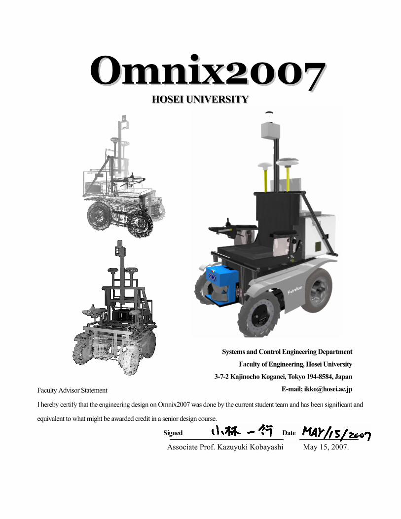
OOmmnniixx22000077 HHHOOOSSSEEEIII UUUNNNIIIVVVEEERRRSSSIIITTTYYY
Faculty Advisor Statement
I hereby certify that the engineering design on Omnix2007 was done by the current student team and has been significant and
equivalent to what might be awarded credit in a senior design course.
Signed Date
Associate Prof. Kazuyuki Kobayashi May 15, 2007.
SSLAM
* reused from the Omnix2006
Systems and Control Engineering Department
Faculty of Engineering, Hosei University
3-7-2 Kajinocho Koganei, Tokyo 194-8584, Japan
E-mail; [email protected]
1
1. Introduction
The Autonomous Robotics Lab (ARL) team of Hosei University is proud to present an innovative,
improved version of the Omnix2007 to the 15th annual Intelligent Ground Vehicle Competition
(IGVC). Building upon previous successes, the Omnix2007 has been updated to meet the demands of
the IGVC with more intelligence and innovative features.
The newly-developed Omnix2007 is based on the Omnix2006 chassis. The concept of the Omnix2007
is a personal transportation vehicle for the coming aging society such as in Japan. As society rapidly
grays, demands for safe and helpful wheelchairs are increasing. To maintain quality of life for the
elderly such as by providing mobility to participate in society, we must reduce the physical and
psychological burden that walking imposes and provide pedestrian environments where the elderly and
physically impaired people can walk or drive safely and comfortably. To achieve this, the Omnix2007
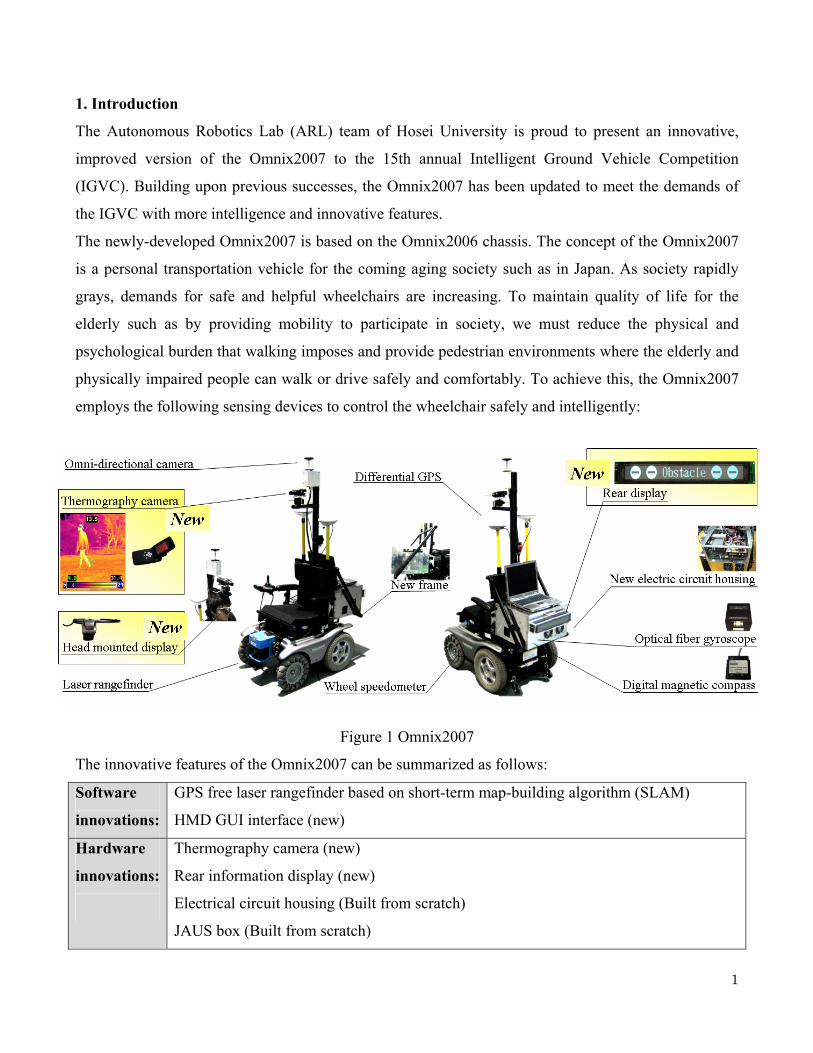
employs the following sensing devices to control the wheelchair safely and intelligently:
Figure 1 Omnix2007
The innovative features of the Omnix2007 can be summarized as follows:
Software
innovations:
GPS free laser rangefinder based on short-term map-building algorithm (SLAM)
HMD GUI interface (new)
Hardware
innovations:
Thermography camera (new)
Rear information display (new)
Electrical circuit housing (Built from scratch)
JAUS box (Built from scratch)
2
We installed a high-contrast vacuum fluorescent display (VFD) board to ensure the safety of people
behind the vehicle; this display shows the vehicle’s actions so that people behind can take avoidance
action in case of turning and emergency stop.
A thermography camera is also newly employed. The combination of thermography camera and laser
rangefinder can detect obstacles in the dark where common vision-based vehicles cannot drive safely.
We developed an intelligent and safe electric wheelchair by applying the latest technologies to the new
chassis. The autonomous wheelchair offers promising potential for next-generation personal
transportation vehicles.
2. Innovation
The key issues in developing a vision-based lane-following autonomous ground vehicle (AGV) are
safety, accuracy and robustness of navigation. Obstacles may be randomly arranged, and the vehicle
has to navigate without collision. To avoid obstacle collisions, environment recognition is important.
Conventionally, for both autonomous challenges and navigation challenges in the IGVC, we applied
only a reaction-based obstacle-avoiding algorithm. However, by using a wide range of laser
rangefinder information, real-time map-building based on detected obstacle positions is possible. This
year, we totally rewrote the autonomous algorithm developed based on the SLAM technique by using
detected obstacle positions. SLAM stands for Simultaneous Localization And Map-building, and a
laser rangefinder and inertial navigation sensors are used as self-localization sensing devices.
GPS is a useful absolute positioning system which can be used for vehicle navigation. However, with
GPS it is sometimes difficult to estimate self-location for outdoor vehicle navigation. Since the spatial
availability of signals depends on satellite locations, the accuracy of measuring vehicle location using
GPS may vary.
SLAM can identify self-position as GPS information. To improve the accuracy of vehicle location, we
developed a new SLAM algorithm suitable for autonomous navigation. The proposed SLAM algorithm
is a landmark-based terrain-aided navigation system that has capabilities for online map-building and
simultaneously utilizing the generated global map.
2.1 Navigation System-based SLAM
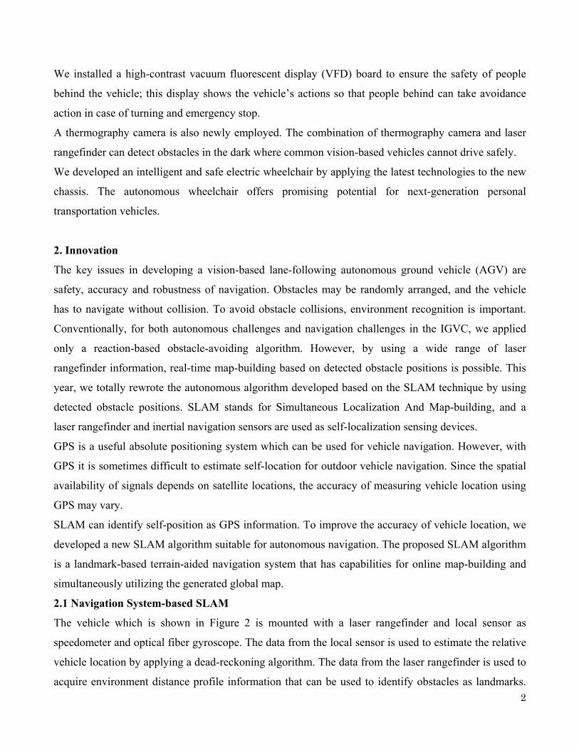
The vehicle which is shown in Figure 2 is mounted with a laser rangefinder and local sensor as
speedometer and optical fiber gyroscope. The data from the local sensor is used to estimate the relative
vehicle location by applying a dead-reckoning algorithm. The data from the laser rangefinder is used to
acquire environment distance profile information that can be used to identify obstacles as landmarks.
3
These data can be fused by applying the Kalman
filter to build an online map, and simultaneously
using the waypoints global map.
Figure 3 compares simulations between the SLAM
method and the dead-reckoning navigation. This
simulation shows vehicle travel apexes of 20
meters square as waypoints for 5 laps.
In the SLAM method, the vehicle travels more
precisely than with the conventional method of
dead-reckoning. The SLAM method allows the
vehicle to navigate waypoints correctly without
GPS. In the navigation challenge, we will apply the
SLAM method which uses a laser rangefinder,
speedometer, optical fiber gyroscope, and GPS data.
The specific system of the SLAM method is
described in Section 7.2, “Navigation Challenge.”
3. Design Process
3.1 Team Organization
The ARL2007 team now has a total of 12 members including 5 new members. Since ARL2006, a total
of 17 members have been involved in the project, so we needed to reconsider the team organization and
design process to match the team size.
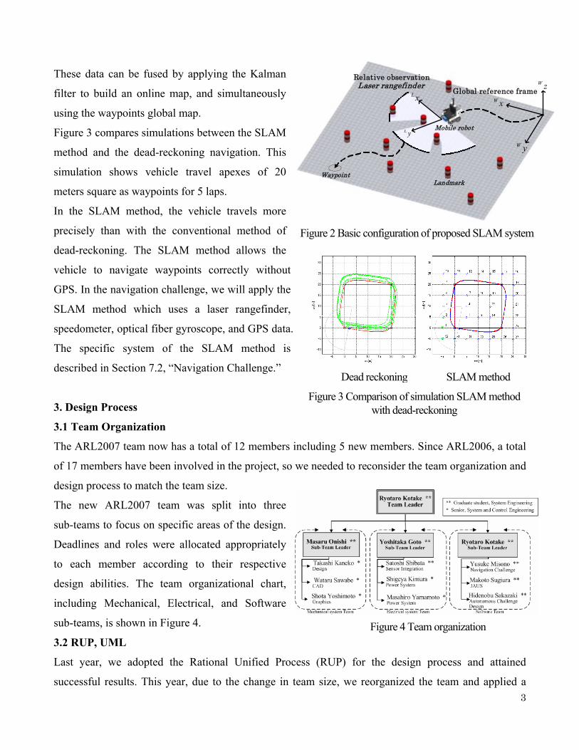
The new ARL2007 team was split into three
sub-teams to focus on specific areas of the design.
Deadlines and roles were allocated appropriately
to each member according to their respective
design abilities. The team organizational chart,
including Mechanical, Electrical, and Software
sub-teams, is shown in Figure 4.
3.2 RUP, UML
Last year, we adopted the Rational Unified Process (RUP) for the design process and attained
successful results. This year, due to the change in team size, we reorganized the team and applied a
Landmark
Relative observation
Mobile robot
Global reference frame
yL
xL
yW
xWzWLaser rangefinder
Waypoint
Figure 2 Basic configuration of proposed SLAM system
SLAM method Dead reckoning
Figure 3 Comparison of simulation SLAM method with dead-reckoning
Figure 4 Team organization
4
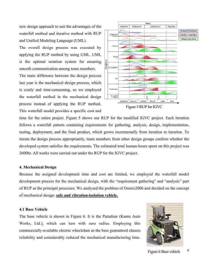
new design approach to suit the advantages of the
waterfall method and iterative method with RUP
and Unified Modeling Language (UML).
The overall design process was executed by
applying the RUP method by using UML. UML
is the optimal notation system for ensuring
smooth communication among team members.
The main difference between the design process
last year is the mechanical design process, which
is costly and time-consuming, so we employed
the waterfall method in the mechanical design
process instead of applying the RUP method.
This waterfall model provides a specific cost and
time for the entire project. Figure 5 shows our RUP for the modified IGVC project. Each iteration
follows a waterfall pattern containing requirements for gathering, analysis, design, implementation,
testing, deployment, and the final product, which grows incrementally from iteration to iteration. To
iterate the design process appropriately, team members from other design groups confirm whether the
developed system satisfies the requirements. The estimated total human-hours spent on this project was
3600hr. All works were carried out under the RUP for the IGVC project.
4. Mechanical Design
Because the assigned development time and cost are limited, we employed the waterfall model
development process for the mechanical design, with the “requirement gathering” and “analysis” part
of RUP as the principal processes. We analyzed the problem of Omnix2006 and decided on the concept
of mechanical design: safe and vibration-isolation vehicle.
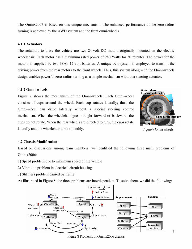
4.1 Base Vehicle
The base vehicle is shown in Figure 6. It is the Patrafour (Kanto Auto
Works, Ltd.), which can turn with zero radius. Employing this
commercially-available electric wheelchair as the base guaranteed chassis
reliability and considerably reduced the mechanical manufacturing time.
Figure 6 Base vehicle
Figure 5 RUP for IGVC
5
The Omnix2007 is based on this unique mechanism. The enhanced performance of the zero-radius
turning is achieved by the AWD system and the front omni-wheels.
4.1.1 Actuators
The actuators to drive the vehicle are two 24-volt DC motors originally mounted on the electric
wheelchair. Each motor has a maximum rated power of 280 Watts for 30 minutes. The power for the
motors is supplied by two 38Ah 12-volt batteries. A unique belt system is employed to transmit the
driving power from the rear motors to the front wheels. Thus, this system along with the Omni-wheels
design enables powerful zero-radius turning as a simple mechanism without a steering actuator.
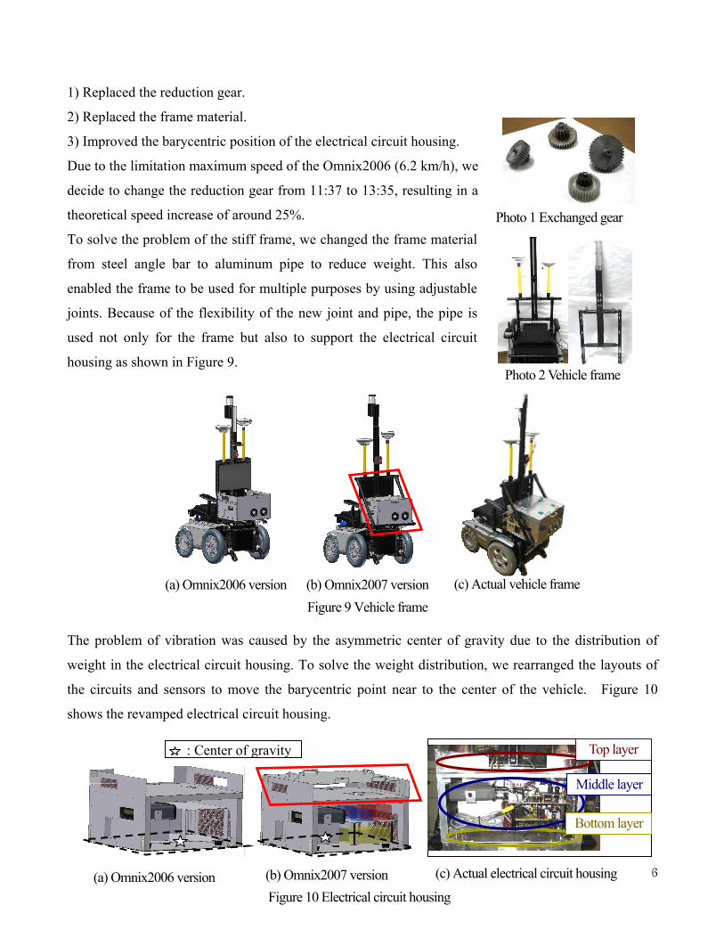
4.1.2 Omni-wheels
Figure 7 shows the mechanism of the Omni-wheels. Each Omni-wheel
consists of cups around the wheel. Each cup rotates laterally; thus, the
Omni-wheel can drive laterally without a special steering control
mechanism. When the wheelchair goes straight forward or backward, the
cups do not rotate. When the rear wheels are directed to turn, the cups rotate
laterally and the wheelchair turns smoothly.
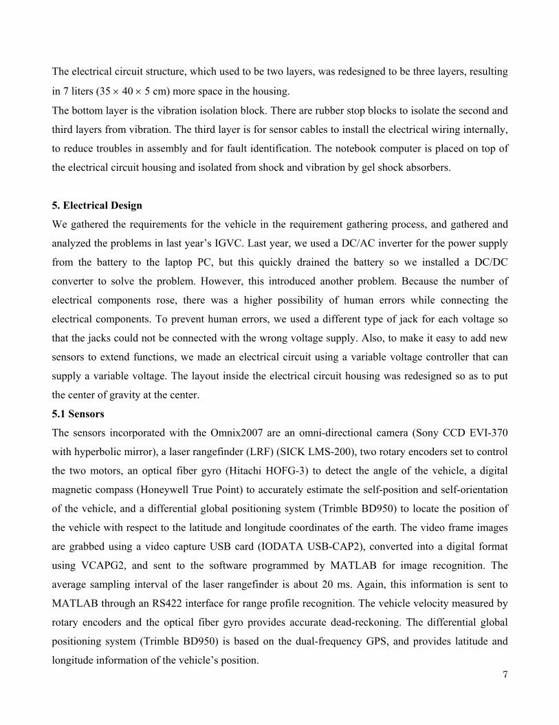
4.2 Chassis Modification
Based on discussions among team members, we identified the following three main problems of
Omnix2006:
1) Speed problem due to maximum speed of the vehicle
2) Vibration problem in electrical circuit housing
3) Stiffness problem caused by frame
As illustrated in Figure 8, the three problems are interdependent. To solve them, we did the following:
Figure 8 Problems of Omnix2006 chassis
Figure 7 Omni wheels
6
Photo 1 Exchanged gear
Photo 2 Vehicle frame
1) Replaced the reduction gear.
2) Replaced the frame material.
3) Improved the barycentric position of the electrical circuit housing.
Due to the limitation maximum speed of the Omnix2006 (6.2 km/h), we
decide to change the reduction gear from 11:37 to 13:35, resulting in a
theoretical speed increase of around 25%.
To solve the problem of the stiff frame, we changed the frame material
from steel angle bar to aluminum pipe to reduce weight. This also
enabled the frame to be used for multiple purposes by using adjustable
joints. Because of the flexibility of the new joint and pipe, the pipe is
used not only for the frame but also to support the electrical circuit
housing as shown in Figure 9.
The problem of vibration was caused by the asymmetric center of gravity due to the distribution of
weight in the electrical circuit housing. To solve the weight distribution, we rearranged the layouts of
the circuits and sensors to move the barycentric point near to the center of the vehicle. Figure 10
shows the revamped electrical circuit housing.
(a) Omnix2006 version Figure 10 Electrical circuit housing (b) Omnix2007 version
(c) Actual electrical circuit housing
Top layer
Middle layer
Bottom layer
: Center of gravity
Figure 9 Vehicle frame (a) Omnix2006 version (b) Omnix2007 version (c) Actual vehicle frame
7
The electrical circuit structure, which used to be two layers, was redesigned to be three layers, resulting
in 7 liters (35 × 40 × 5 cm) more space in the housing.
The bottom layer is the vibration isolation block. There are rubber stop blocks to isolate the second and
third layers from vibration. The third layer is for sensor cables to install the electrical wiring internally,
to reduce troubles in assembly and for fault identification. The notebook computer is placed on top of
the electrical circuit housing and isolated from shock and vibration by gel shock absorbers.
5. Electrical Design
We gathered the requirements for the vehicle in the requirement gathering process, and gathered and
analyzed the problems in last year’s IGVC. Last year, we used a DC/AC inverter for the power supply
from the battery to the laptop PC, but this quickly drained the battery so we installed a DC/DC
converter to solve the problem. However, this introduced another problem. Because the number of
electrical components rose, there was a higher possibility of human errors while connecting the
electrical components. To prevent human errors, we used a different type of jack for each voltage so
that the jacks could not be connected with the wrong voltage supply. Also, to make it easy to add new
sensors to extend functions, we made an electrical circuit using a variable voltage controller that can
supply a variable voltage. The layout inside the electrical circuit housing was redesigned so as to put
the center of gravity at the center.
5.1 Sensors
The sensors incorporated with the Omnix2007 are an omni-directional camera (Sony CCD EVI-370
with hyperbolic mirror), a laser rangefinder (LRF) (SICK LMS-200), two rotary encoders set to control
the two motors, an optical fiber gyro (Hitachi HOFG-3) to detect the angle of the vehicle, a digital
magnetic compass (Honeywell True Point) to accurately estimate the self-position and self-orientation
of the vehicle, and a differential global positioning system (Trimble BD950) to locate the position of
the vehicle with respect to the latitude and longitude coordinates of the earth. The video frame images
are grabbed using a video capture USB card (IODATA USB-CAP2), converted into a digital format
using VCAPG2, and sent to the software programmed by MATLAB for image recognition. The
average sampling interval of the laser rangefinder is about 20 ms. Again, this information is sent to
MATLAB through an RS422 interface for range profile recognition. The vehicle velocity measured by
rotary encoders and the optical fiber gyro provides accurate dead-reckoning. The differential global
positioning system (Trimble BD950) is based on the dual-frequency GPS, and provides latitude and
longitude information of the vehicle’s position.
8
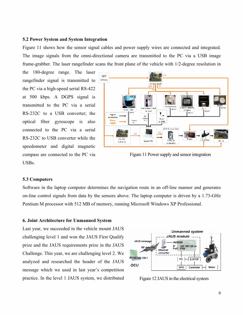
5.2 Power System and System Integration
Figure 11 shows how the sensor signal cables and power supply wires are connected and integrated.
The image signals from the omni-directional camera are transmitted to the PC via a USB image
frame-grabber. The laser rangefinder scans the front plane of the vehicle with 1/2-degree resolution in
the 180-degree range. The laser
rangefinder signal is transmitted to
the PC via a high-speed serial RS-422
at 500 kbps. A DGPS signal is
transmitted to the PC via a serial
RS-232C to a USB converter; the
optical fiber gyroscope is also
connected to the PC via a serial
RS-232C to USB converter while the
speedometer and digital magnetic
compass are connected to the PC via
USBs.
5.3 Computers
Software in the laptop computer determines the navigation route in an off-line manner and generates
on-line control signals from data by the sensors above. The laptop computer is driven by a 1.73-GHz
Pentium M processor with 512 MB of memory, running Microsoft Windows XP Professional.
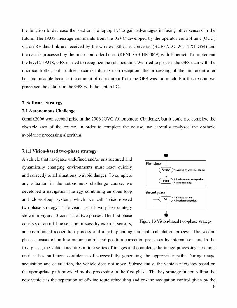
6. Joint Architecture for Unmanned System
Last year, we succeeded in the vehicle mount JAUS
challenging level 1 and won the JAUS First Qualify
prize and the JAUS requirements prize in the JAUS
Challenge. This year, we are challenging level 2. We
analyzed and researched the header of the JAUS
message which we used in last year’s competition
practice. In the level 1 JAUS system, we distributed Figure 12 JAUS in the electrical system
Figure 11 Power supply and sensor integration
9
Figure 13 Vision-based two-phase strategy
the function to decrease the load on the laptop PC to gain advantages in fusing other sensors in the
future. The JAUS message commands from the IGVC developed by the operator control unit (OCU)
via an RF data link are received by the wireless Ethernet converter (BUFFALO WLI-TX1-G54) and
the data is processed by the microcontroller board (RENESAS H8/3069) with Ethernet. To implement
the level 2 JAUS, GPS is used to recognize the self-position. We tried to process the GPS data with the
microcontroller, but troubles occurred during data reception: the processing of the microcontroller
became unstable because the amount of data output from the GPS was too much. For this reason, we
processed the data from the GPS with the laptop PC.
7. Software Strategy
7.1 Autonomous Challenge
Omnix2006 won second prize in the 2006 IGVC Autonomous Challenge, but it could not complete the
obstacle area of the course. In order to complete the course, we carefully analyzed the obstacle
avoidance processing algorithm.
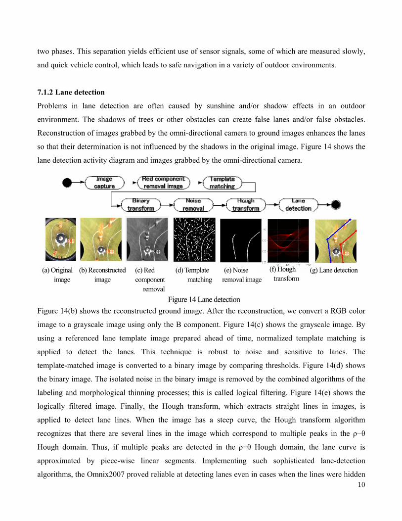
7.1.1 Vision-based two-phase strategy
A vehicle that navigates undefined and/or unstructured and
dynamically changing environments must react quickly
and correctly to all situations to avoid danger. To complete
any situation in the autonomous challenge course, we
developed a navigation strategy combining an open-loop
and closed-loop system, which we call “vision-based
two-phase strategy”. The vision-based two-phase strategy
shown in Figure 13 consists of two phases. The first phase
consists of an off-line sensing process by external sensors,
an environment-recognition process and a path-planning and path-calculation process. The second
phase consists of on-line motor control and position-correction processes by internal sensors. In the
first phase, the vehicle acquires a time-series of images and completes the image-processing iterations
until it has sufficient confidence of successfully generating the appropriate path. During image
acquisition and calculation, the vehicle does not move. Subsequently, the vehicle navigates based on
the appropriate path provided by the processing in the first phase. The key strategy in controlling the
new vehicle is the separation of off-line route scheduling and on-line navigation control given by the
10
two phases. This separation yields efficient use of sensor signals, some of which are measured slowly,
and quick vehicle control, which leads to safe navigation in a variety of outdoor environments.
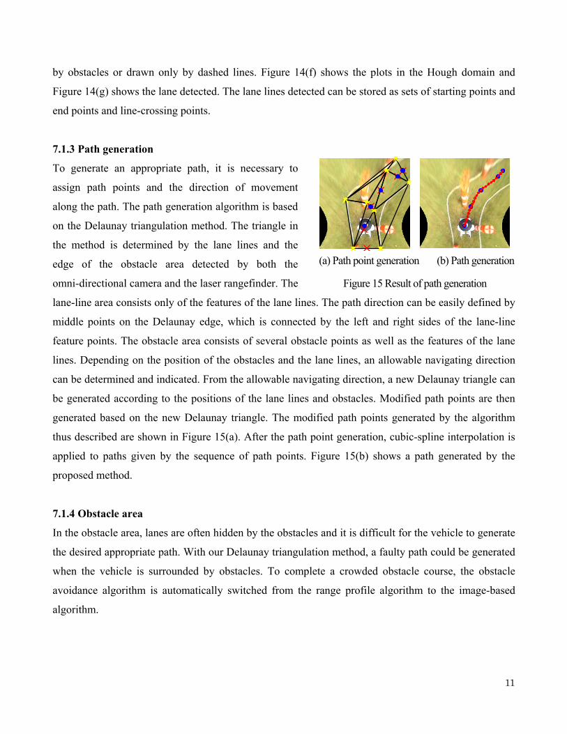
7.1.2 Lane detection
Problems in lane detection are often caused by sunshine and/or shadow effects in an outdoor
environment. The shadows of trees or other obstacles can create false lanes and/or false obstacles.
Reconstruction of images grabbed by the omni-directional camera to ground images enhances the lanes
so that their determination is not influenced by the shadows in the original image. Figure 14 shows the
lane detection activity diagram and images grabbed by the omni-directional camera.
Figure 14(b) shows the reconstructed ground image. After the reconstruction, we convert a RGB color
image to a grayscale image using only the B component. Figure 14(c) shows the grayscale image. By
using a referenced lane template image prepared ahead of time, normalized template matching is
applied to detect the lanes. This technique is robust to noise and sensitive to lanes. The
template-matched image is converted to a binary image by comparing thresholds. Figure 14(d) shows
the binary image. The isolated noise in the binary image is removed by the combined algorithms of the
labeling and morphological thinning processes; this is called logical filtering. Figure 14(e) shows the
logically filtered image. Finally, the Hough transform, which extracts straight lines in images, is
applied to detect lane lines. When the image has a steep curve, the Hough transform algorithm
recognizes that there are several lines in the image which correspond to multiple peaks in the ρ−θ
Hough domain. Thus, if multiple peaks are detected in the ρ−θ Hough domain, the lane curve is
approximated by piece-wise linear segments. Implementing such sophisticated lane-detection
algorithms, the Omnix2007 proved reliable at detecting lanes even in cases when the lines were hidden
(b) Reconstructed image
(a) Original image
(c) Red component
removal i
(d) Template matching
(g) Lane detection (e) Noise removal image
(f) Hough transform
Figure 14 Lane detection
11
by obstacles or drawn only by dashed lines. Figure 14(f) shows the plots in the Hough domain and
Figure 14(g) shows the lane detected. The lane lines detected can be stored as sets of starting points and
end points and line-crossing points.
7.1.3 Path generation
To generate an appropriate path, it is necessary to
assign path points and the direction of movement
along the path. The path generation algorithm is based
on the Delaunay triangulation method. The triangle in
the method is determined by the lane lines and the
edge of the obstacle area detected by both the
omni-directional camera and the laser rangefinder. The
lane-line area consists only of the features of the lane lines. The path direction can be easily defined by
middle points on the Delaunay edge, which is connected by the left and right sides of the lane-line
feature points. The obstacle area consists of several obstacle points as well as the features of the lane
lines. Depending on the position of the obstacles and the lane lines, an allowable navigating direction
can be determined and indicated. From the allowable navigating direction, a new Delaunay triangle can
be generated according to the positions of the lane lines and obstacles. Modified path points are then
generated based on the new Delaunay triangle. The modified path points generated by the algorithm
thus described are shown in Figure 15(a). After the path point generation, cubic-spline interpolation is
applied to paths given by the sequence of path points. Figure 15(b) shows a path generated by the
proposed method.
7.1.4 Obstacle area
In the obstacle area, lanes are often hidden by the obstacles and it is difficult for the vehicle to generate
the desired appropriate path. With our Delaunay triangulation method, a faulty path could be generated
when the vehicle is surrounded by obstacles. To complete a crowded obstacle course, the obstacle
avoidance algorithm is automatically switched from the range profile algorithm to the image-based
algorithm.
Figure 15 Result of path generation
(a) Path point generation (b) Path generation
12
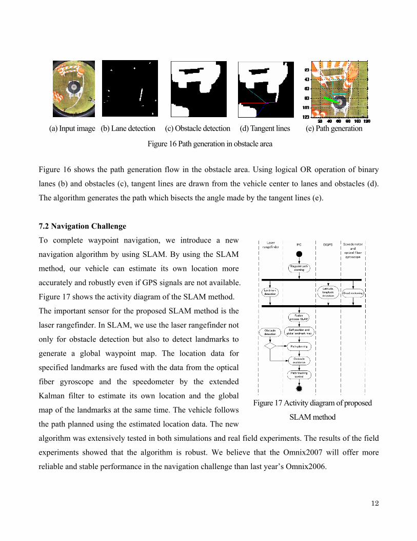
Figure 16 shows the path generation flow in the obstacle area. Using logical OR operation of binary
lanes (b) and obstacles (c), tangent lines are drawn from the vehicle center to lanes and obstacles (d).
The algorithm generates the path which bisects the angle made by the tangent lines (e).
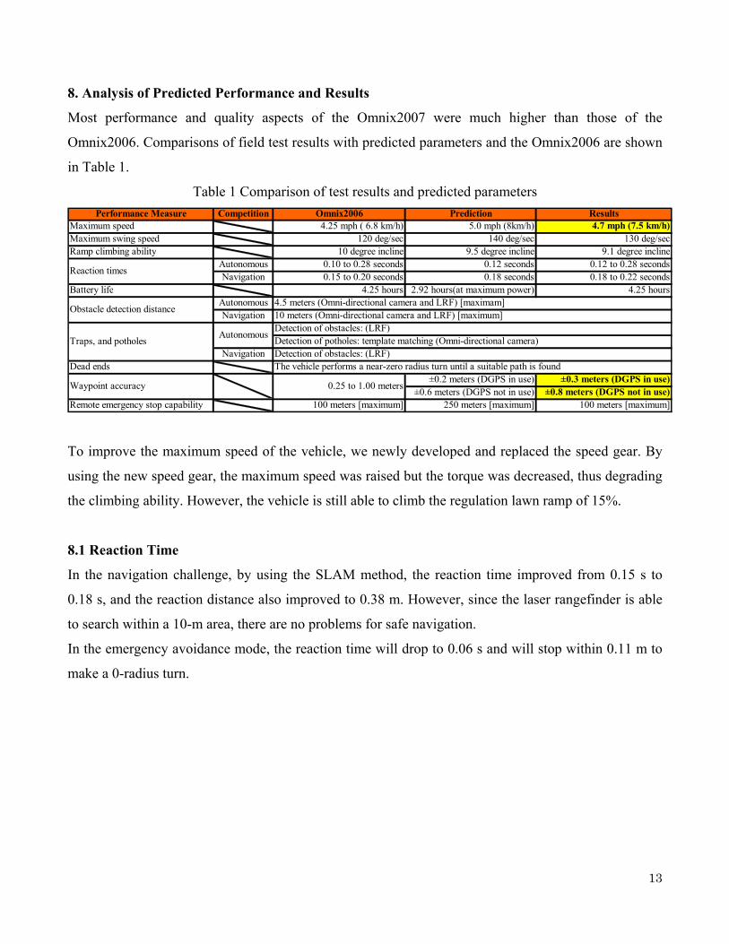
7.2 Navigation Challenge
To complete waypoint navigation, we introduce a new
navigation algorithm by using SLAM. By using the SLAM
method, our vehicle can estimate its own location more
accurately and robustly even if GPS signals are not available.
Figure 17 shows the activity diagram of the SLAM method.
The important sensor for the proposed SLAM method is the
laser rangefinder. In SLAM, we use the laser rangefinder not
only for obstacle detection but also to detect landmarks to
generate a global waypoint map. The location data for
specified landmarks are fused with the data from the optical
fiber gyroscope and the speedometer by the extended
Kalman filter to estimate its own location and the global
map of the landmarks at the same time. The vehicle follows
the path planned using the estimated location data. The new
algorithm was extensively tested in both simulations and real field experiments. The results of the field
experiments showed that the algorithm is robust. We believe that the Omnix2007 will offer more
reliable and stable performance in the navigation challenge than last year’s Omnix2006.
Figure 17 Activity diagram of proposed
SLAM method
(a) Input image (b) Lane detection (c) Obstacle detection (d) Tangent lines (e) Path generation
Figure 16 Path generation in obstacle area
13
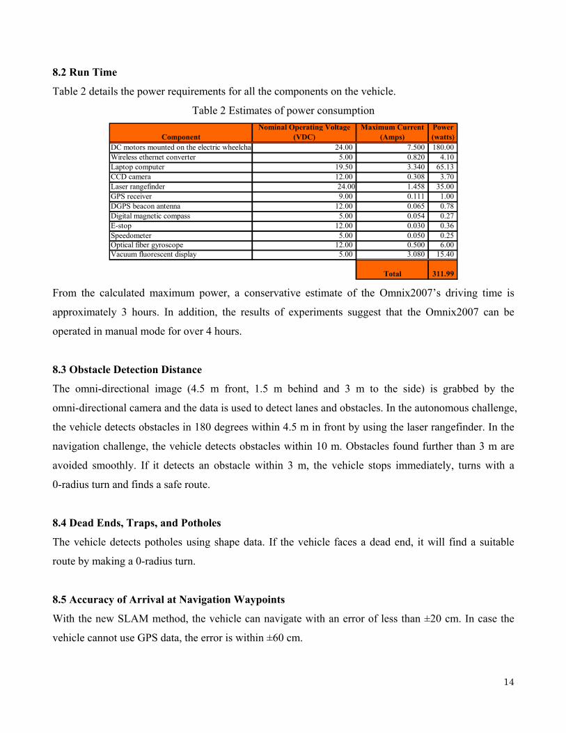
8. Analysis of Predicted Performance and Results
Most performance and quality aspects of the Omnix2007 were much higher than those of the
Omnix2006. Comparisons of field test results with predicted parameters and the Omnix2006 are shown
in Table 1.
Table 1 Comparison of test results and predicted parameters Performance Measure Competition Omnix2006 Prediction Results
Maximum speed 4.25 mph ( 6.8 km/h) 5.0 mph (8km/h) 4.7 mph (7.5 km/h)Maximum swing speed 120 deg/sec 140 deg/sec 130 deg/secRamp climbing ability 10 degree incline 9.5 degree incline 9.1 degree incline
Autonomous 0.10 to 0.28 seconds 0.12 seconds 0.12 to 0.28 secondsNavigation 0.15 to 0.20 seconds 0.18 seconds 0.18 to 0.22 seconds
Battery life 4.25 hours 2.92 hours(at maximum power) 4.25 hoursAutonomousNavigation
NavigationDead ends
±0.2 meters (DGPS in use) ±0.3 meters (DGPS in use)±0.6 meters (DGPS not in use) ±0.8 meters (DGPS not in use)
Remote emergency stop capability 100 meters [maximum] 250 meters [maximum] 100 meters [maximum]
0.25 to 1.00 meters
The vehicle performs a near-zero radius turn until a suitable path is found
Waypoint accuracy
Traps, and potholesAutonomous
Detection of obstacles: (LRF)Detection of potholes: template matching (Omni-directional camera)Detection of obstacles: (LRF)
Reaction times
Obstacle detection distance4.5 meters (Omni-directional camera and LRF) [maximam]10 meters (Omni-directional camera and LRF) [maximum]
To improve the maximum speed of the vehicle, we newly developed and replaced the speed gear. By
using the new speed gear, the maximum speed was raised but the torque was decreased, thus degrading
the climbing ability. However, the vehicle is still able to climb the regulation lawn ramp of 15%.
8.1 Reaction Time
In the navigation challenge, by using the SLAM method, the reaction time improved from 0.15 s to
0.18 s, and the reaction distance also improved to 0.38 m. However, since the laser rangefinder is able
to search within a 10-m area, there are no problems for safe navigation.
In the emergency avoidance mode, the reaction time will drop to 0.06 s and will stop within 0.11 m to
make a 0-radius turn.
14
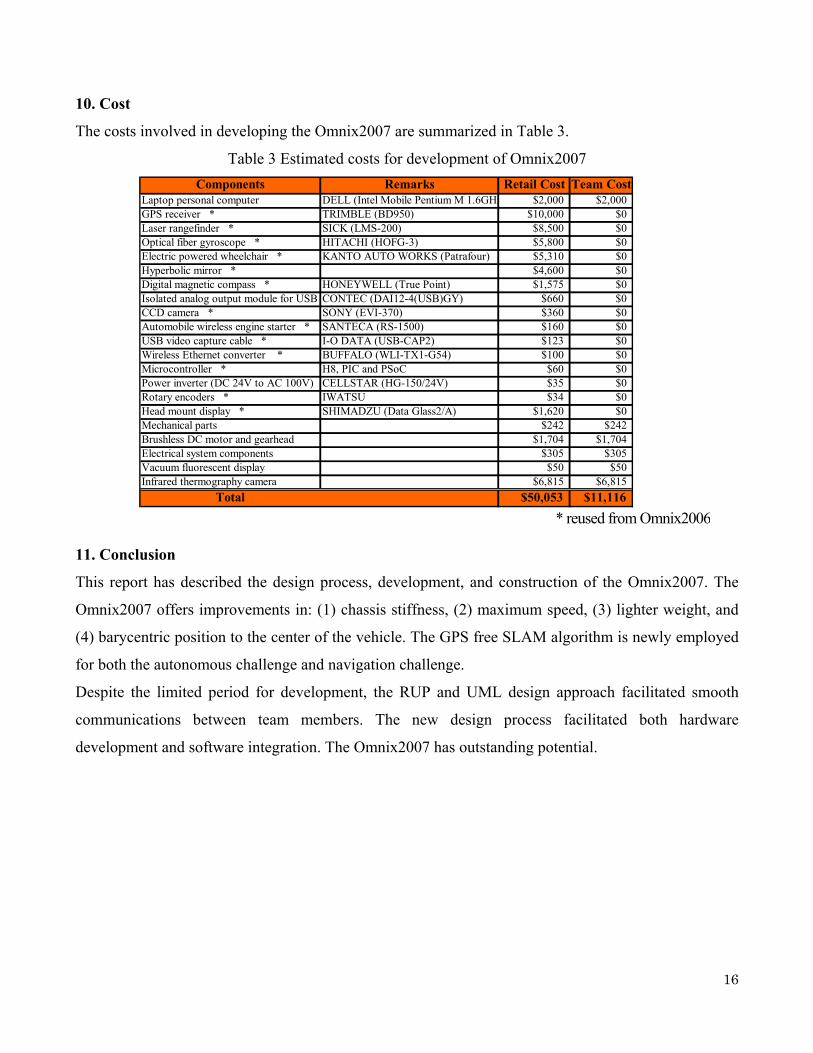
8.2 Run Time
Table 2 details the power requirements for all the components on the vehicle.
Table 2 Estimates of power consumption
ComponentNominal Operating Voltage
(VDC)Maximum Current
(Amps)Power(watts)
DC motors mounted on the electric wheelchai 24.00 7.500 180.00Wireless ethernet converter 5.00 0.820 4.10Laptop computer 19.50 3.340 65.13CCD camera 12.00 0.308 3.70Laser rangefinder 24.00 1.458 35.00GPS receiver 9.00 0.111 1.00DGPS beacon antenna 12.00 0.065 0.78Digital magnetic compass 5.00 0.054 0.27E-stop 12.00 0.030 0.36Speedometer 5.00 0.050 0.25Optical fiber gyroscope 12.00 0.500 6.00Vacuum fluorescent display 5.00 3.080 15.40
Total 311.99 From the calculated maximum power, a conservative estimate of the Omnix2007’s driving time is
approximately 3 hours. In addition, the results of experiments suggest that the Omnix2007 can be
operated in manual mode for over 4 hours.
8.3 Obstacle Detection Distance
The omni-directional image (4.5 m front, 1.5 m behind and 3 m to the side) is grabbed by the
omni-directional camera and the data is used to detect lanes and obstacles. In the autonomous challenge,
the vehicle detects obstacles in 180 degrees within 4.5 m in front by using the laser rangefinder. In the
navigation challenge, the vehicle detects obstacles within 10 m. Obstacles found further than 3 m are
avoided smoothly. If it detects an obstacle within 3 m, the vehicle stops immediately, turns with a
0-radius turn and finds a safe route.
8.4 Dead Ends, Traps, and Potholes
The vehicle detects potholes using shape data. If the vehicle faces a dead end, it will find a suitable
route by making a 0-radius turn.
8.5 Accuracy of Arrival at Navigation Waypoints
With the new SLAM method, the vehicle can navigate with an error of less than ±20 cm. In case the
vehicle cannot use GPS data, the error is within ±60 cm.

15
9. Safety, Reliability, Durability
9.1 Safety
For safety, we designed the Omnix2007 from the two perspectives of mechanical and electrical
designs.
In the mechanical design, we examined the safety of operators and spectators at the competition and
decided to reduce the sharp edges and corners of the vehicle by changing the frame material from sharp
steel angle bar to round aluminum pipe.
In the electrical design, we designed two different types of emergency stop (E-stop) to follow the rules
of IGVC. The Omnix2007 has a remote controlled E-stop and a vehicle-mounted E-stop push-button.
The signal of the remote-controlled E-stop is transmitted by an automobile wireless engine starter,
which can transmit signals over a wide range with a maximum distance of about 100 m (330 feet). In
addition, the E-stop push-button is located on the mast of the vehicle so that it can be found and
accessed easily.
9.2 Reliability
The reliability of the Omnix2007 has been improved by totally redesigning the electrical circuit
housing and using new stiff frames. In the electrical design, the power supply jack is designed to
prevent connection to wrong voltages to prevent human errors.
9.3 Durability
We changed the frame material from steel angle bar to aluminum pipe. The new frame is significantly
stronger and more rigid than last year’s frame. The frame also supports the electrical circuit housing to
prevent vibration caused by running. In order to extend battery life, we changed the power supply
circuits from DC/AC inverter to DC/DC converter.
16
10. Cost
The costs involved in developing the Omnix2007 are summarized in Table 3.
Table 3 Estimated costs for development of Omnix2007
11. Conclusion
This report has described the design process, development, and construction of the Omnix2007. The
Omnix2007 offers improvements in: (1) chassis stiffness, (2) maximum speed, (3) lighter weight, and
(4) barycentric position to the center of the vehicle. The GPS free SLAM algorithm is newly employed
for both the autonomous challenge and navigation challenge.
Despite the limited period for development, the RUP and UML design approach facilitated smooth
communications between team members. The new design process facilitated both hardware
development and software integration. The Omnix2007 has outstanding potential.
Components Remarks Retail Cost Team CostLaptop personal computer DELL (Intel Mobile Pentium M 1.6GHz $2,000 $2,000GPS receiver * TRIMBLE (BD950) $10,000 $0Laser rangefinder * SICK (LMS-200) $8,500 $0Optical fiber gyroscope * HITACHI (HOFG-3) $5,800 $0Electric powered wheelchair * KANTO AUTO WORKS (Patrafour) $5,310 $0Hyperbolic mirror * $4,600 $0Digital magnetic compass * HONEYWELL (True Point) $1,575 $0Isolated analog output module for USB CONTEC (DAI12-4(USB)GY) $660 $0CCD camera * SONY (EVI-370) $360 $0Automobile wireless engine starter * SANTECA (RS-1500) $160 $0USB video capture cable * I-O DATA (USB-CAP2) $123 $0Wireless Ethernet converter * BUFFALO (WLI-TX1-G54) $100 $0Microcontroller * H8, PIC and PSoC $60 $0Power inverter (DC 24V to AC 100V) CELLSTAR (HG-150/24V) $35 $0Rotary encoders * IWATSU $34 $0Head mount display * SHIMADZU (Data Glass2/A) $1,620 $0Mechanical parts $242 $242Brushless DC motor and gearhead $1,704 $1,704Electrical system components $305 $305Vacuum fluorescent display $50 $50Infrared thermography camera $6,815 $6,815
Total $50,053 $11,116
* reused from Omnix2006