Embed Size (px)
Citation preview
Alcatel-Lucent Enterprise OmniAccess Stellar AP User Guide - AWOS 4.0.1 January 2021 033517-10 Rev.C
The Alcatel-Lucent name and logo are trademarks of Nokia used under license by ALE. To view other trademarks used by affiliated companies of ALE Holding, visit: www.al-enterprise.com/en/legal/trademarks-copyright. All other trademarks are the property of their respective owners. The information presented is subject to change without notice. Neither ALE Holding nor any of its affiliates assumes any responsibility for inaccuracies contained herein.
How to Use This Manual
Stellar AP User Guide ALCATEL-LUCENT ENTERPRISE 2
Contents 1 How to Use This Manual ............................................................................................. 7
Access Stellar AP Through the GUI .................................................................................... 7
Document Conventions .................................................................................................. 7
2 Configuration Sample ................................................................................................ 8
Scenario 1: AP Group Without ALE OXO server ...................................................................... 8
Scenario 2: AP Group With ALE OXO Server (ZTP) ................................................................. 10
3 Connecting AP Group via Web Browser ......................................................................... 12
Prerequisites for Setting up and Accessing AP Group .............................................................. 12
Connect to Pre-defined SSID and Browse URL ...................................................................... 12
Using the Initializing Wizard .......................................................................................... 13
Connecting to the AP Group via Web ................................................................................ 16
PVM/SVM Election and AP Group Scalability ........................................................................ 16
4 Introduction to the AP Group Web Management System .................................................... 18
Dashboard Overview .................................................................................................... 18
WLAN Window ........................................................................................................ 18
AP Window ............................................................................................................ 20
Client Window ........................................................................................................ 23
Monitoring Window .................................................................................................. 25
System Page ............................................................................................................. 28
General Window ...................................................................................................... 28
System Time Window ................................................................................................ 33
Syslog & SNMP Window .............................................................................................. 34
Wireless Page ............................................................................................................ 36
RF Window ............................................................................................................ 36
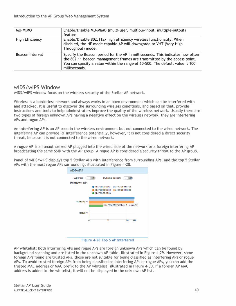
wIDS/wIPS Window ................................................................................................... 40
Performance Optimization Window ............................................................................... 43
Access Page .............................................................................................................. 44
Authentication Window ............................................................................................. 45
Customized Portal Page Panel ..................................................................................... 48
Customized Portal Page – Login by Account ...................................................................... 49
Customized Portal Page – Login by Access Code ................................................................. 49
Customized Portal Page – Login by Terms of Use ................................................................ 49
Black List & White List Window .................................................................................... 50
Access Control List Window......................................................................................... 53
Network Page............................................................................................................ 54
5 WLAN Configuration ................................................................................................ 55
Create New WLAN ...................................................................................................... 55

How to Use This Manual
Stellar AP User Guide ALCATEL-LUCENT ENTERPRISE 3
Create an Enterprise WLAN ......................................................................................... 55
Create a Personal WLAN ............................................................................................ 60
Create a Captive Portal WLAN ..................................................................................... 64
Delete Your WLAN ...................................................................................................... 67
Modify Your WLAN ...................................................................................................... 68
Modify WLAN QoS ....................................................................................................... 68
6 AP Management...................................................................................................... 70
AP Group Management ................................................................................................. 70
Import and Export AP Configuration ................................................................................. 72
Upgrade AP Firmware .................................................................................................. 73
Modify AP Name and IP Address ...................................................................................... 75
Check AP Configuration Detail ........................................................................................ 76
Modify AP Transmission Power and Channel ........................................................................ 77
AP LED Specification ................................................................................................... 78
Locate AP or Turn LED Off ............................................................................................. 78
Remove an AP from the Group ........................................................................................ 79
Allow an AP to Join the Group ........................................................................................ 80
How to Add a New AP to Group ....................................................................................... 80
How to Replace a Current AP in Group .............................................................................. 81
How to Setup Wireless Networks With large scale of Stellar APs ................................................ 81
How to Configure the AP if There is No DHCP server .............................................................. 81
7 Authentication Management ...................................................................................... 82
Authentication and Encryption Methods ............................................................................. 82
How to Configure Captive Portal Authentication ................................................................... 85
Create a Captive Portal WLAN ..................................................................................... 85
Enable Captive Portal Service ...................................................................................... 85
Select Your Login Method ........................................................................................... 86
Create Users or Access Code ....................................................................................... 86
Customize Your Splash Page (Optional) ........................................................................... 88
Log User Behavior (Optional) ....................................................................................... 88
Specify Your Walled Garden (Optional) ........................................................................... 89
Specify Your Captive Portal Whitelist (Optional) ................................................................ 89
8 Tools ................................................................................................................... 91
PMD .................................................................................................................... 92
Reset the AP to Factory Default Settings ......................................................................... 92
SSH Secure shell ...................................................................................................... 92
9 AP UI ................................................................................................................... 93
Login to AP UI ......................................................................................................... 93
AP Interface ........................................................................................................... 94
AP Network ........................................................................................................... 95
How to Use This Manual
Stellar AP User Guide ALCATEL-LUCENT ENTERPRISE 4
Configure Mesh/Bridge through AP UI ............................................................................. 95
Configure DHCP through AP UI ..................................................................................... 99
Configure DNS Cache through AP UI ............................................................................. 100
Configure NAT through AP UI ..................................................................................... 100
Configure Static Neighbor AP through AP UI ................................................................... 101
RF Environment .................................................................................................... 102
10 Web Management with HTTPS .................................................................................. 105
Download the Certificate from AP ................................................................................. 105
Install the Certificate on Different Platform accordingly ....................................................... 106
Case A: Microsoft Windows + Microsoft IE/Google Chrome .................................................. 106
Case B: Microsoft Windows + Mozilla Firefox ................................................................... 109
Case C: Apple MAC OS X + Google Chrome ..................................................................... 112
Case D: Apple MAC OS X + Mozilla Firefox ...................................................................... 116
A. End-User Software License Agreement ....................................................................... 117
Table of Figures
Figure 2-1 AP group without OXO ........................................................................................ 8 Figure 2-2 AP group with OXO ........................................................................................... 10 Figure 3-1 AP Group Login Page ......................................................................................... 13 Figure 3-2 Initialization Wizard-Welcome Page ....................................................................... 14 Figure 3-3 Initialization Wizard-Modify Administrator Password ................................................... 14 Figure 3-4 Initialization Wizard-Select country code and time zone ............................................... 14 Figure 3-5 Initialization Wizard-Create New WLAN ................................................................... 15 Figure 3-6 Initialization Wizard-Complete Notice .................................................................... 16 Figure 4-1 Dashboard Overview ......................................................................................... 18 Figure 4-2 WLAN Window-Simplified Mode ............................................................................ 19 Figure 4-3 WLAN Window-Advanced Mode ............................................................................. 19 Figure 4-4 AP Window-Simplified Mode ................................................................................ 20 Figure 4-5 AP Window-Advanced Mode ................................................................................. 21 Figure 4-6 Clients Window-Simplified Mode ........................................................................... 23 Figure 4-7 Clients Window-Advanced Mode ............................................................................ 24 Figure 4-8 Monitoring Window - AP Group ............................................................................. 25 Figure 4-9 Monitoring Window - WLAN ................................................................................. 26 Figure 4-10 Monitoring Window - AP .................................................................................... 27 Figure 4-11 Monitoring Window - Client ................................................................................ 27 Figure 4-12 System page ................................................................................................. 28 Figure 4-13 General Window – Simplified Mode ....................................................................... 29 Figure 4-14 General Configuration Window –Advanced Mode ....................................................... 29 Figure 4-15 Account Management Tab ................................................................................. 30 Figure 4-16 Account Lockout............................................................................................. 31 Figure 4-17 Command line Account ..................................................................................... 31 Figure 4-18 Certificate Management Tab .............................................................................. 32 Figure 4-19 Service Management Tab .................................................................................. 33 Figure 4-20 System Time Window ....................................................................................... 33 Figure 4-21 Syslog Window ............................................................................................... 34 Figure 4-22 SNMP Window ................................................................................................ 35 Figure 4-23 Wireless Page ................................................................................................ 36 Figure 4-24 RF-2.4GHz .................................................................................................... 37
How to Use This Manual
Stellar AP User Guide ALCATEL-LUCENT ENTERPRISE 5
Figure 4-25 RF-5GHz ...................................................................................................... 37 Figure 4-26 RF Configuration Window .................................................................................. 38 Figure 4-27 Edit RF Information ......................................................................................... 39 Figure 4-28 Top 5 AP interfered ......................................................................................... 40 Figure 4-29 wIDS/wIPS Configuration Window ........................................................................ 41 Figure 4-30 Foreign AP Whitelist ........................................................................................ 42 Figure 4-31 Foreign AP Black List ....................................................................................... 42 Figure 4-32 Wireless Optimization Tab ................................................................................. 43 Figure 4-33 Access Page .................................................................................................. 45 Figure 4-34 Authentication Window – Simplified Mode ............................................................... 45 Figure 4-35 Authentication Window – Internal Portal Server ........................................................ 46 Figure 4-36 Authentication Window – External Portal Server ....................................................... 46 Figure 4-37 Customized Portal Page .................................................................................... 48 Figure 4-38 Customized Portal Page – Login by account ............................................................. 49 Figure 4-39 Customized Portal Page – Login by access code ........................................................ 49 Figure 4-40 Customized Portal Page – Login by Terms of use ....................................................... 50 Figure 4-41 Customized Portal Page – Terms of use .................................................................. 50 Figure 4-42 Black List Tab ................................................................................................ 51 Figure 4-43 White List Tab ............................................................................................... 51 Figure 4-44 Walled Garden Tab ......................................................................................... 52 Figure 4-45 Multicast Control Tab ....................................................................................... 52 Figure 4-46 ACL Window – Simplified Mode ............................................................................ 53 Figure 4-47 ACL Window – Advanced Mode ............................................................................ 53 Figure 4-48 Network Page ................................................................................................ 54 Figure 5-1 Create Enterprise WLAN - Simplified Mode ............................................................... 56 Figure 5-2 Create Enterprise WLAN - Advanced Mode ................................................................ 57 Figure 5-3 Create Personal WLAN - Simplified Mode ................................................................. 60 Figure 5-4 Create Personal WLAN - Advanced Mode .................................................................. 61 Figure 5-5 Create Captive Portal WLAN - Simplified Mode .......................................................... 64 Figure 5-6 Create Captive Portal WLAN - Advanced Mode ........................................................... 65 Figure 5-7 Delete a WLAN ................................................................................................ 68 Figure 5-8 Modify a WLAN ................................................................................................ 68 Figure 5-9 Modify WLAN QoS ............................................................................................. 69 Figure 6-1 AP Group Configuration Window ........................................................................... 71 Figure 6-2 AP Group Information Location ............................................................................. 71 Figure 6-3 AP Group Management IP .................................................................................... 71 Figure 6-4 Export AP Group Configuration ............................................................................. 72 Figure 6-5 Import AP Group Configuration ............................................................................. 72 Figure 6-6 Update Single AP using Local Image File .................................................................. 73 Figure 6-7 Update Single AP from Remote TFTP Server.............................................................. 74 Figure 6-8 Update all APs’ Firmware ................................................................................... 74 Figure 6-9 Modify AP Name .............................................................................................. 75 Figure 6-10 Modify AP IP Address ........................................................................................ 76 Figure 6-11 Check AP Configuration Detail ............................................................................ 77 Figure 6-12 RF Management ............................................................................................. 77 Figure 6-13 Turn LED off ................................................................................................. 78 Figure 6-14 Locate AP..................................................................................................... 79 Figure 6-15 Restore AP state ............................................................................................. 79 Figure 6-16 Remove an AP from Group ................................................................................. 80 Figure 6-17 Allow AP to join group ...................................................................................... 80 Figure 7-1 Enterprise Authentication ................................................................................... 83 Figure 7-2 SOHO Authentication ......................................................................................... 83 Figure 7-3 Authentication Security Type-Personal .................................................................... 84 Figure 7-4 Authentication Security Type-Enterprise.................................................................. 84 Figure 7-5 Create Captive Portal type WLAN .......................................................................... 85 Figure 7-6 Enable Captive Portal Service .............................................................................. 86

How to Use This Manual
Stellar AP User Guide ALCATEL-LUCENT ENTERPRISE 6
Figure 7-7 Select Your Login Method ................................................................................... 86 Figure 7-8 Create Captive Portal Users ................................................................................. 87 Figure 7-9 Create Access Code .......................................................................................... 88 Figure 7-10 Customize Your Splash Page ............................................................................... 88 Figure 7-11 Log User Behavior ........................................................................................... 89 Figure 7-12 Wall Garden .................................................................................................. 89 Figure 7-13 Portal Whitelist .............................................................................................. 90 Figure 8-1 Tools in Dashboard ........................................................................................... 91 Figure 8-2 Troubleshooting Command .................................................................................. 91 Figure 8-3 PMD ............................................................................................................. 92 Figure 9-1 AP List – link to AP UI ........................................................................................ 93 Figure 9-2 AP UI............................................................................................................ 94 Figure 9-3 AP Interface ................................................................................................... 94 Figure 9-4 AP Network .................................................................................................... 95 Figure 9-5 MESH Topology ................................................................................................ 96 Figure 9-6 Configure Mesh Root ....................................................................................... 97 Figure 9-7 Configure Mesh Leaf.......................................................................................... 97 Figure 9-8 Configure Wireless Bridge ................................................................................. 98 Figure 9-9 DHCP Server in AP group .................................................................................... 99 Figure 9-10 DHCP Server .................................................................................................. 99 Figure 9-11 Source NAT ................................................................................................. 100 Figure 9-12 Destination NAT ........................................................................................... 101 Figure 9-13 Auto Neighbor AP ......................................................................................... 102 Figure 9-14 Static Neighbor AP ........................................................................................ 102 Figure 9-15 RF Environment............................................................................................ 103 Figure 9-16 RF Scanning Data .......................................................................................... 103 Figure 9-17 Wireless Packet Capture ................................................................................. 104 Figure 10-1 HTTP Login Page .......................................................................................... 105 Figure 10-2 Download Certificate from AP ........................................................................... 106 Figure 10-3 Case A – Step 1 ............................................................................................ 106 Figure 10-4 Case A – Step 2 ............................................................................................ 107 Figure 10-5 Case A – Step 3 ............................................................................................ 107 Figure 10-6 Case A – Step 4 ............................................................................................ 108 Figure 10-7 Case A – Step 5 ............................................................................................ 108 Figure 10-8 Case A – Step 6 ............................................................................................ 109 Figure 10-9 Case B – Step 1 ............................................................................................ 109 Figure 10-10 Case B – Step 2 ........................................................................................... 110 Figure 10-11 Case B – Step 3 ........................................................................................... 110 Figure 10-12 Case B – Step 4 ........................................................................................... 111 Figure 10-13 Case B – Step 5 ........................................................................................... 111 Figure 10-14 Case C – Step 1 ........................................................................................... 112 Figure 10-15 Case C – Step 2 ........................................................................................... 112 Figure 10-16 Case C – Step 3 ........................................................................................... 113 Figure 10-17 Case C – Step 4 ........................................................................................... 113 Figure 10-18 Case C – Step 5 ........................................................................................... 114 Figure 10-19 Case C – Step 6 ........................................................................................... 114 Figure 10-20 Case C – Step 7 ........................................................................................... 115 Figure 10-21 Case C – Step 8 ........................................................................................... 115 Figure 10-22 Case C – Step 9 ........................................................................................... 116
How to Use This Manual
Stellar AP User Guide ALCATEL-LUCENT ENTERPRISE 7
1 How to Use This Manual
This manual describes all features supported by the Stellar AP and provides instructions and examples for
configuring ALE series OmniAccess Stellar Access Point (AP). It is designed for network administrators who
are responsible for configuring and maintaining the Wi-Fi network. It assumes the reader is familiar with
Layer2 and Layer3 networks and 802.11 protocols and related technologies. The manual covers an
introduction to the Stellar AP and configuration samples. The examples describe the general steps of setting
up a Wi-Fi network based on several typical deployment scenarios. It is useful for those new to the ALE Access
Point configuration and those already familiar with the software wanting to know more about certain
functions.
Access Stellar AP Through the GUI
This manual is developed for the Stellar AP GUI (Wi-Fi Express mode). Each Stellar AP supports up to three
simultaneous GUI connections. The GUI is accessible through a standard web browser from a remote
management console or workstation. The GUI includes configuration wizards that guide you to change
administrator password and complete basic WLAN configuration. In addition to the wizards, the GUI includes
a Dashboard monitoring feature that provides visibility into your wireless network’s performance and usage.
This allows you to easily locate and diagnose WLAN issues. For details on the GUI Dashboard, see Dashboard
Overview.
Document Conventions
The following conventions are used throughout this manual to emphasize important concepts:
It indicates helpful suggestions, pertinent information, and important things to remember.
It indicates a risk of damage to your hardware or loss of data or some incorrect or improper operation that
should be avoided.
Configuration Sample
Stellar AP User Guide ALCATEL-LUCENT ENTERPRISE 8
2 Configuration Sample
This chapter describes the general steps to configure the Stellar AP with respect to several deployment
topologies. Follow the configuration steps in the guide to configure your Stellar AP. This chapter contains
the following topics:
AP Group without ALE OXO server
AP Group with ALE OXO server (ZTP)
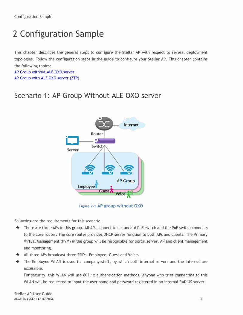
Scenario 1: AP Group Without ALE OXO server
Figure 2-1 AP group without OXO
Following are the requirements for this scenario,
➔ There are three APs in this group. All APs connect to a standard PoE switch and the PoE switch connects
to the core router. The core router provides DHCP server function to both APs and clients. The Primary
Virtual Management (PVM) in the group will be responsible for portal server, AP and client management
and monitoring.
➔ All three APs broadcast three SSIDs: Employee, Guest and Voice.
➔ The Employee WLAN is used for company staff, by which both internal servers and the internet are
accessible.
For security, this WLAN will use 802.1x authentication methods. Anyone who tries connecting to this
WLAN will be requested to input the user name and password registered in an internal RADIUS server.
Configuration Sample
Stellar AP User Guide ALCATEL-LUCENT ENTERPRISE 9
➔ The Guest WLAN is designed for guests and can access the internet ONLY. It uses a captive portal
authentication and a portal page will pop up when browsing any website. Guest can access the Internet
only after inputting the access code or user name and password provided by the network administrator.
The splash page can be customized to the customer’s style.
➔ The Voice WLAN is designed for VoIP application ONLY. It will authorize voice traffic to be highest
priority in QoS profile so as to provide a stable voice connection. The SSID will be hidden and
inaccessible to both internal and external networks.
➔ ALL APs usage and client connections are visible in the UI dashboard.
According to the topology, the clients are separate in three service VLANs (For example: VLAN 100, VLAN 200
and VLAN 300) while APs are in the management VLAN (default VLAN of the switch ports, for example: VLAN
1). The APs and clients will be assigned an IP address from the DHCP server via the router. The router is the
default gateway for APs and clients. Following are the detailed configuration steps:
➔ Step1: Configure a PoE switch as follows:
1) The ports used to connect the APs have their default (untagged) VLAN as the AP management VLAN;
2) Add tagged VLANs to the ports for all WLANs that will be created on the APs;
3) Tag (trunk) all of the user and AP-Management VLANs on the uplink between the switch and the
router.
➔ Step2: Connect all APs to the PoE switch and all APs will obtain an IP address from the DHCP server.
Login to the AP group, change the administrator password and initially create WLAN ‘Employee’ using
the wizard. Refer to Connect to pre-defined SSID and browse URL and Using the Initializing Wizard for
details. Refer to Modify Your WLAN to set the mapping VLAN for WLAN ‘Employee’.
➔ Step3: Create WLAN ‘Guest’ as per the steps in ‘Create New WLAN’ and configure the captive portal
authentication according to ‘How to configure captive portal authentication’.
➔ Step4: Create WLAN ‘Voice’ as per the steps in ‘Create New WLAN’.
➔ Step5: Configure ACLs according to Access Control List to restrict the access domain of each WLAN.
➔ Step6: Check AP, Client and monitor the performance in the dashboard. Refer to Dashboard Overview
for detail.
Configuration Sample
Stellar AP User Guide ALCATEL-LUCENT ENTERPRISE 10
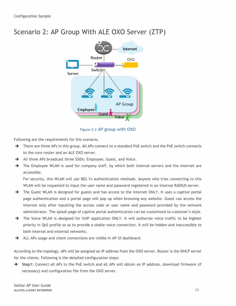
Scenario 2: AP Group With ALE OXO Server (ZTP)
Figure 2-2 AP group with OXO
Following are the requirements for this scenario,
➔ There are three APs in this group. All APs connect to a standard PoE switch and the PoE switch connects
to the core router and an ALE OXO server.
➔ All three APs broadcast three SSIDs: Employee, Guest, and Voice.
➔ The Employee WLAN is used for company staff, by which both internal servers and the internet are
accessible.
For security, this WLAN will use 802.1x authentication methods. Anyone who tries connecting to this
WLAN will be requested to input the user name and password registered in an internal RADIUS server.
➔ The Guest WLAN is designed for guests and has access to the internet ONLY. It uses a captive portal
page authentication and a portal page will pop up when browsing any website. Guest can access the
Internet only after inputting the access code or user name and password provided by the network
administrator. The splash page of captive portal authentication can be customized to customer’s style.
➔ The Voice WLAN is designed for VoIP application ONLY. It will authorize voice traffic to be highest
priority in QoS profile so as to provide a stable voice connection. It will be hidden and inaccessible to
both internal and external networks.
➔ ALL APs usage and client connections are visible in AP UI dashboard.
According to the topology, APs will be assigned an IP address from the OXO server. Router is the DHCP server
for the clients. Following is the detailed configuration steps:
➔ Step1: Connect all APs to the PoE switch and all APs will obtain an IP address, download firmware (if
necessary) and configuration file from the OXO server.

Configuration Sample
Stellar AP User Guide ALCATEL-LUCENT ENTERPRISE 11
➔ Step2: The APs will reboot automatically to setup a group and allow configuration from the OXO server
take effect, all three WLANs are created.
➔ Step3: Check AP, Client and monitor the performance in the dashboard. Refer to Dashboard Overview
for detail.
Connecting AP Group via Web Browser
Stellar AP User Guide ALCATEL-LUCENT ENTERPRISE 12
3 Connecting AP Group via Web Browser
Prerequisites for Setting up and Accessing AP Group
• Connect all APs to switch and power up.
• Ensure that a DHCP server is present and accessible in the network. The AP group uses an external DHCP server for IP address management of the access points and the wireless clients.
• Ensure that a DNS server is available in the network, which helps to parse the web URL used to access the AP. (Refer to Note 3-1)
• It is recommended that your configuring terminal should have a compatible operating system and browser.
Recommended OS Recommended Browser
Windows 7 Window 8 Window 10 MAC OS X 10.10 MAC OS X 10.11
Google Chrome 48 and later Mozilla Firefox 48 and later Internet Explorer 11 and later
After above prerequisites are met, proceed to: Connect to pre-defined SSID and browse URL.
Note 3-1: The process of connecting to a single AP through web is same as connecting to AP group.
Note 3-2: It is recommended to connect only one AP at a time to the network and complete the configuration,
then plug in other APs one by one to synchronize the configurations.
Connect to Pre-defined SSID and Browse URL
The ALE WLAN solution is based on a cluster architecture. A maximum of 255 APs are supported in one AP
cluster/group. All APs have the same cluster ID that uniquely defines the AP group and all APs have to be in
the same VLAN because the communication between group members is based on multicast. The group will
select the Primary Virtual Manager (PVM) and Secondary Virtual Manager (SVM) based on AP model and MAC
address, more details refer to PVM/SVM Election and AP Group Scalability. The PVM is responsible for the
group management, such as configuration synchronization, usage data statistics, firmware upgrading, etc.
and the SVM is the backup of the PVM. By default, the AP group will advertise the pre-defined SSID ‘mywifi-
xxxx’ and you can connect to ‘mywifi-xxxx’ to browse the AP group GUI through http://mywifi.al-
enterprise.com:8080 to the initializing wizard. After you complete Using the Initializing Wizard, the SSID
‘mywifi-xxxx’ will be deleted. (‘xxxx’ is the last two bytes of PVM’s MAC address)
Note 3-3: Besides the HTTP login method (port 8080), you can also login to the web manager using HTTPS
protocol with the URL https://mywifi.al-enterprise.com , more details please refer to Web management with
HTTPS
Note 3-4: If there is no DNS server in the network, you can connect to the AP group directly using the IP address of any
AP in the group, accessing “http://a.b.c.d:8080”. (a.b.c.d is the AP’s IP address)
Connecting AP Group via Web Browser
Stellar AP User Guide ALCATEL-LUCENT ENTERPRISE 13
Note 3-5: If there is no DHCP server in the network, the AP will default to the 192.168.1.254 address. See How to
Configure the AP if there is no DHCP server.
Stellar AP1230 series and AP1311 Access Points can be powered with dual uplinks, with both switch ports POE enabled
only when connected to a standalone or VC of OmniSwitch 6860/E.
• When using dual links, both switch ports should be of speed 1GE and configured as Linkagg (LACP).
• On the slots used for POE, enable capacitor-detection and then connect the ports to Access Points (lanpower <slot>
capacitor-detection enable). Save and certify switch configuration.
• AP1230 series and AP1311 Access Points will always get powered by either uplink, and if the main source goes down,
the backup POE link will power up the Access Point.
Stellar AP1230 series and AP1311 when not POE powered using OmniSwitch 6860/E, but other LAN switches, you can
still use dual uplinks, but please ensure only one uplink is POE enabled.
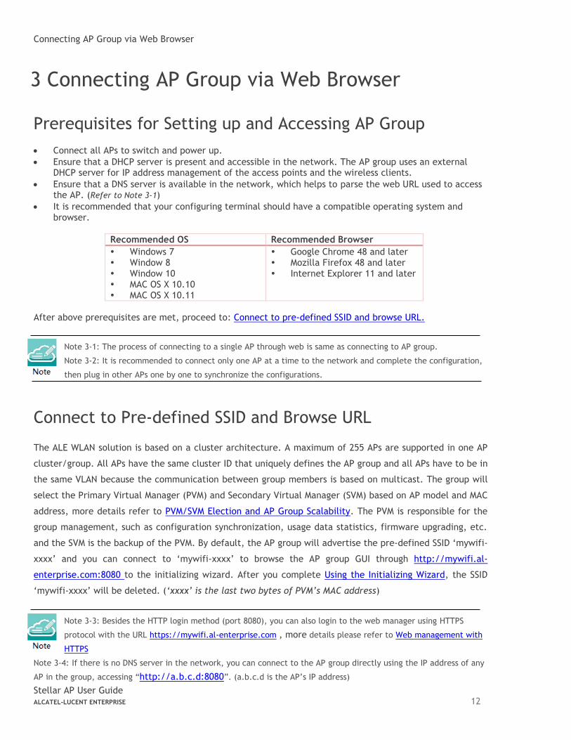
Using the Initializing Wizard
Initializing wizard page is loaded by connecting to the pre-defined SSID accessing the URL http://mywifi.al-
enterprise.com:8080. Login with the Administrator account and the default password ‘admin’, illustrated in
Figure 3-1. If you want to manage the AP group with HTTPS protocol, refer to Web management with HTTPS.
Figure 3-1 AP Group Login Page
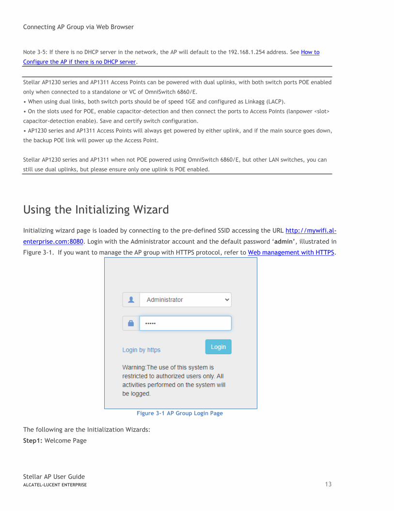
The following are the Initialization Wizards:
Step1: Welcome Page
Connecting AP Group via Web Browser
Stellar AP User Guide ALCATEL-LUCENT ENTERPRISE 14
Figure 3-2 Initialization Wizard-Welcome Page
Step2: Change your Administrator password.
Figure 3-3 Initialization Wizard-Modify Administrator Password
Note 3-6: It is highly recommended and a best security practice to change the default passwords for
the predefined login accounts.
Step3: Select your country code and time zone. (Only for -RW models)
Figure 3-4 Initialization Wizard-Select country code and time zone
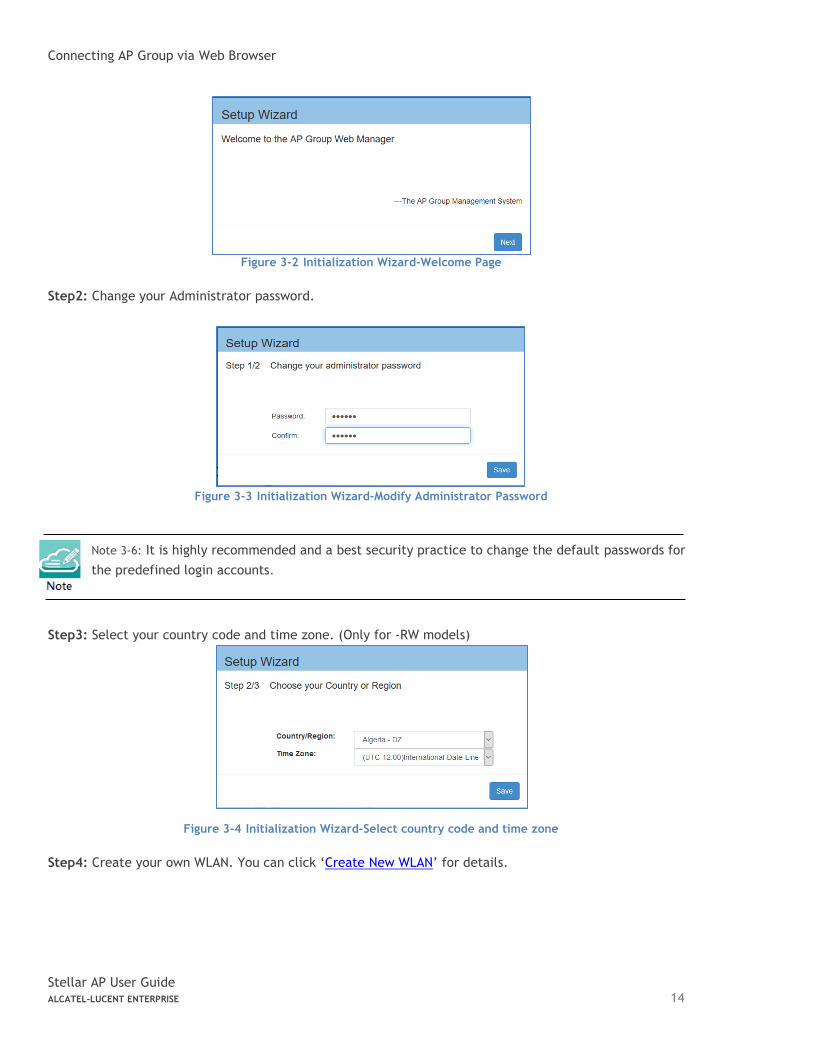
Step4: Create your own WLAN. You can click ‘Create New WLAN’ for details.
Connecting AP Group via Web Browser
Stellar AP User Guide ALCATEL-LUCENT ENTERPRISE 15
Figure 3-5 Initialization Wizard-Create New WLAN
Note 3-7: The VLAN assignment for the WLAN is not available in the initial wizard phase. You can modify the mapping VLAN value after the initial setup is completed, using the steps described in “Modify your WLAN” section which can be used to modify existing WLANs.
Connecting AP Group via Web Browser
Stellar AP User Guide ALCATEL-LUCENT ENTERPRISE 16
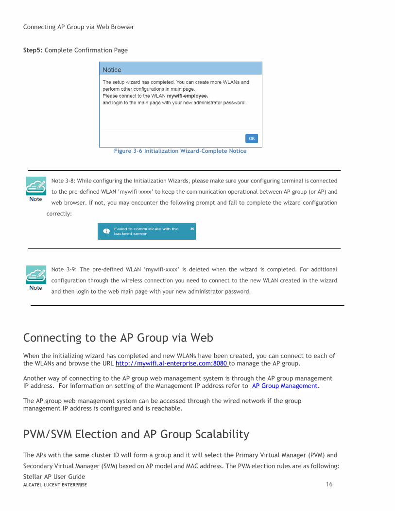
Step5: Complete Confirmation Page
Figure 3-6 Initialization Wizard-Complete Notice
Note 3-8: While configuring the Initialization Wizards, please make sure your configuring terminal is connected
to the pre-defined WLAN ’mywifi-xxxx’ to keep the communication operational between AP group (or AP) and
web browser. If not, you may encounter the following prompt and fail to complete the wizard configuration
correctly:
Note 3-9: The pre-defined WLAN ’mywifi-xxxx’ is deleted when the wizard is completed. For additional
configuration through the wireless connection you need to connect to the new WLAN created in the wizard
and then login to the web main page with your new administrator password.
Connecting to the AP Group via Web
When the initializing wizard has completed and new WLANs have been created, you can connect to each of the WLANs and browse the URL http://mywifi.al-enterprise.com:8080 to manage the AP group. Another way of connecting to the AP group web management system is through the AP group management IP address. For information on setting of the Management IP address refer to AP Group Management. The AP group web management system can be accessed through the wired network if the group management IP address is configured and is reachable.
PVM/SVM Election and AP Group Scalability
The APs with the same cluster ID will form a group and it will select the Primary Virtual Manager (PVM) and
Secondary Virtual Manager (SVM) based on AP model and MAC address. The PVM election rules are as following:
Connecting AP Group via Web Browser
Stellar AP User Guide ALCATEL-LUCENT ENTERPRISE 17
1. PVM/SVM election priority:
AP1320/AP1360 > AP1311 > AP1220/AP1230/AP1251/AP1201 > AP1101/AP1201H/AP1201L/AP1201HL
2. Among the APs with same priority, the one with highest MAC address will be selected as PVM, the second
highest MAC address AP will be selected as SVM.
3. AP1101/AP1201H/AP1201L/AP1201HL as PVM in the cluster, it can scale to 32 APs.
4. AP1320/AP1360/AP1311/AP1220/AP1230/AP1251/AP1201 as PVM in the cluster, it can scale to 255 APs.
5. The idea in general is to be able to have enough resiliency in the network design, so if there is a cluster
size >64 always there is either (AP1220 series, AP1230 series, A1251, AP1320 series or AP1360 series,
AP1311) to take up PVM/SVM role. Recommend in network segments of every 64 APs there are at least
4x APs of either AP1220 series, AP1230 series, AP1251, AP1320 series, AP1360 series or AP1311.
6. For resiliency deployment, to scale to 64 APs you will need at least 4 AP12XX (AP1220/AP1230/AP1251)
or 4 AP13xx (AP1320/AP1360/AP1311) in the cluster.
7. For resiliency deployment, to scale even further for 255 APs you will need at least 16 AP12XX
(AP1220/AP1230/AP1251) or 16 AP13XX (AP1320/AP1360/AP1311) in the cluster.
8. If AP1201 coexists with AP1220/AP1230/AP1251 in the same cluster, and AP1201 is selected as PVM by
the system automatically, suggest to manually intervene and turn one of the AP1220/AP1230/AP1251 to
be PVM for better management performance consideration. (See “Update to PVM” parameter in Chapter 4 –
AP Window)
9. If a higher priority AP joins an existed AP group, it will take over the PVM role. For example, an AP1221
will become PVM after it joins an existed pure AP1101 group, and the old PVM will change to SVM or
member in the AP group.
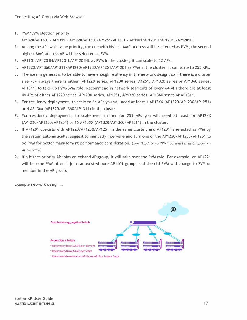
Example network design …
Introduction to the AP Group Web Management System
Stellar AP User Guide ALCATEL-LUCENT ENTERPRISE 18
4 Introduction to the AP Group Web Management System
Dashboard Overview
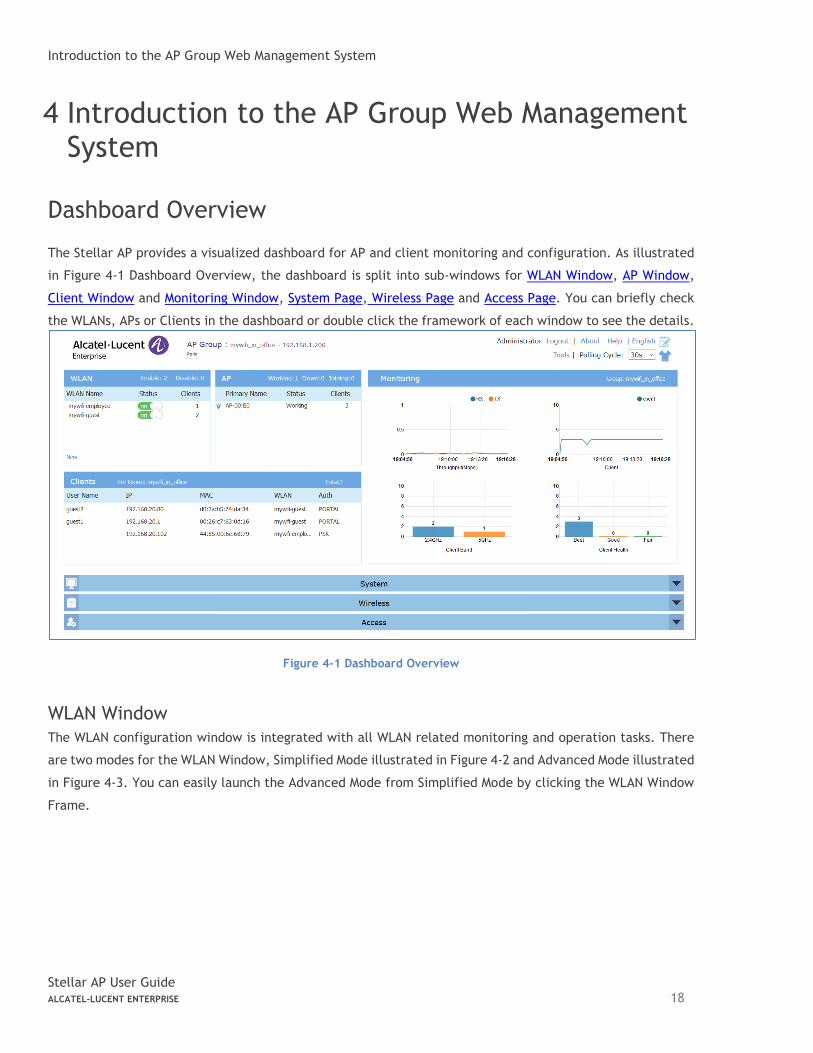
The Stellar AP provides a visualized dashboard for AP and client monitoring and configuration. As illustrated
in Figure 4-1 Dashboard Overview, the dashboard is split into sub-windows for WLAN Window, AP Window,
Client Window and Monitoring Window, System Page, Wireless Page and Access Page. You can briefly check
the WLANs, APs or Clients in the dashboard or double click the framework of each window to see the details.
Figure 4-1 Dashboard Overview
WLAN Window
The WLAN configuration window is integrated with all WLAN related monitoring and operation tasks. There
are two modes for the WLAN Window, Simplified Mode illustrated in Figure 4-2 and Advanced Mode illustrated
in Figure 4-3. You can easily launch the Advanced Mode from Simplified Mode by clicking the WLAN Window
Frame.
Introduction to the AP Group Web Management System
Stellar AP User Guide ALCATEL-LUCENT ENTERPRISE 19
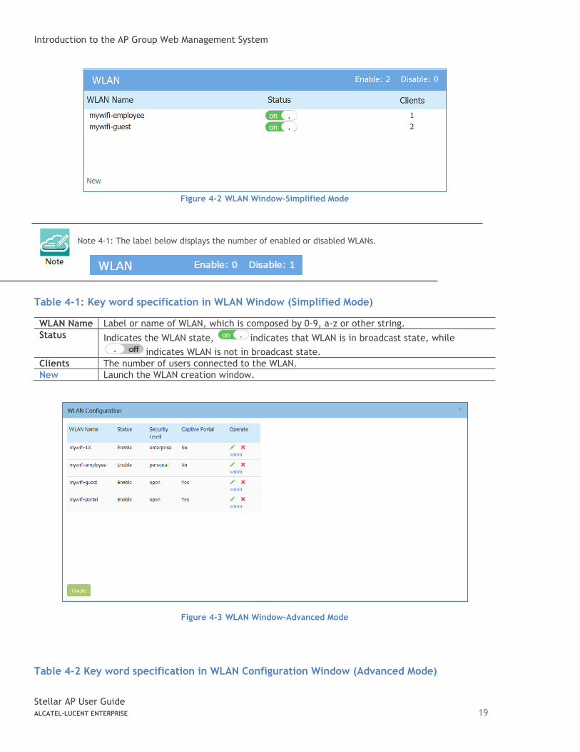
Figure 4-2 WLAN Window-Simplified Mode
Note 4-1: The label below displays the number of enabled or disabled WLANs.
Table 4-1: Key word specification in WLAN Window (Simplified Mode)
WLAN Name Label or name of WLAN, which is composed by 0-9, a-z or other string.
Status Indicates the WLAN state, indicates that WLAN is in broadcast state, while
indicates WLAN is not in broadcast state.
Clients The number of users connected to the WLAN.
New Launch the WLAN creation window.
Figure 4-3 WLAN Window-Advanced Mode
Table 4-2 Key word specification in WLAN Configuration Window (Advanced Mode)
Introduction to the AP Group Web Management System
Stellar AP User Guide ALCATEL-LUCENT ENTERPRISE 20
WLAN Name Label or name of WLAN.
Status Indicates the WLAN state, indicates that WLAN is in broadcast state, while
indicates WLAN is not in broadcast state.
Security Level Security Level of WLAN, from high to low is Enterprise>Personal>Open.
Captive Portal Indicates whether the WLAN is using captive portal authentication. Yes means the WLAN is configured with captive portal authentication, while No means the WLAN is without captive portal authentication.
Operate Operation for the WLAN. see Modify Your WLAN, see Delete Your WLAN, see Modify WLAN QoS.
Link for Creating new WLAN, see Create New WLAN.
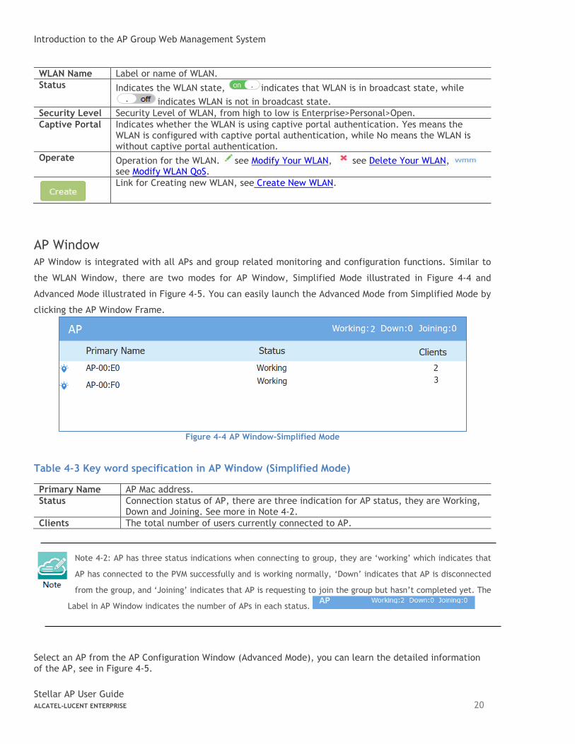
AP Window
AP Window is integrated with all APs and group related monitoring and configuration functions. Similar to
the WLAN Window, there are two modes for AP Window, Simplified Mode illustrated in Figure 4-4 and
Advanced Mode illustrated in Figure 4-5. You can easily launch the Advanced Mode from Simplified Mode by
clicking the AP Window Frame.
Figure 4-4 AP Window-Simplified Mode
Table 4-3 Key word specification in AP Window (Simplified Mode)
Primary Name AP Mac address.
Status Connection status of AP, there are three indication for AP status, they are Working, Down and Joining. See more in Note 4-2.
Clients The total number of users currently connected to AP.
Note 4-2: AP has three status indications when connecting to group, they are ‘working’ which indicates that
AP has connected to the PVM successfully and is working normally, ‘Down’ indicates that AP is disconnected
from the group, and ‘Joining’ indicates that AP is requesting to join the group but hasn’t completed yet. The
Label in AP Window indicates the number of APs in each status.
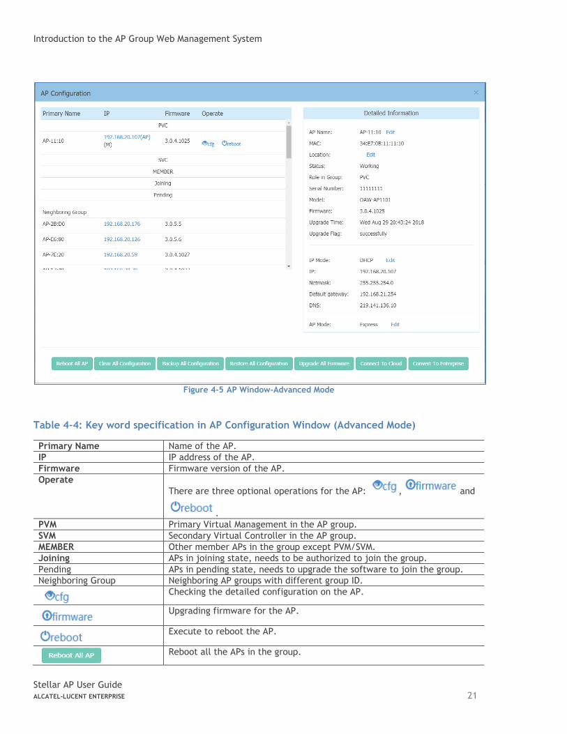
Select an AP from the AP Configuration Window (Advanced Mode), you can learn the detailed information of the AP, see in Figure 4-5.
Introduction to the AP Group Web Management System
Stellar AP User Guide ALCATEL-LUCENT ENTERPRISE 21
Figure 4-5 AP Window-Advanced Mode
Table 4-4: Key word specification in AP Configuration Window (Advanced Mode)
Primary Name Name of the AP.
IP IP address of the AP.
Firmware Firmware version of the AP.
Operate
There are three optional operations for the AP: , and
.
PVM Primary Virtual Management in the AP group.
SVM Secondary Virtual Controller in the AP group.
MEMBER Other member APs in the group except PVM/SVM.
Joining APs in joining state, needs to be authorized to join the group.
Pending APs in pending state, needs to upgrade the software to join the group.
Neighboring Group Neighboring AP groups with different group ID.
Checking the detailed configuration on the AP.
Upgrading firmware for the AP.
Execute to reboot the AP.
Reboot all the APs in the group.
Introduction to the AP Group Web Management System
Stellar AP User Guide ALCATEL-LUCENT ENTERPRISE 22
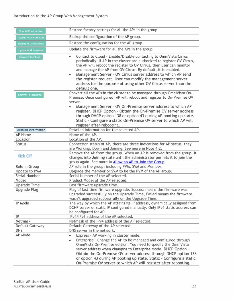
Restore factory settings for all the APs in the group.
Backup the configuration of the AP group.
Restore the configuration for the AP group.
Update the firmware for all the APs in the group.
• Contact to Cloud – Enable/Disable contacting to OmniVista Cirrus
periodically. If AP in the cluster are authorized to register OV Cirrus, the AP will reboot the register to OV Cirrus, then user can monitor and manage the AP from OV Cirrus. By default, it is enabled.
• Management Server – OV Cirrus server address to which AP send the register request. User can modify the management server address for the purpose of using other OV Cirrus server than the default one.
Convert all the APs in the cluster to be managed through OmniVista On-Premise. Once configured, AP will reboot and register to On-Premise OV server.
• Management Server – OV On-Premise server address to which AP register. DHCP Option – Obtain the On-Premise OV server address through DHCP option 138 or option 43 during AP booting up state. Static – Configure a static On-Premise OV server to which AP will register after rebooting.
Detailed information for the selected AP.
AP Name Name of the AP.
Location Location of the AP.
Status Connection status of AP, there are three indications for AP status, they are Working, Down and Joining. See more in Note 4-2.
Remove the AP from the group. When an AP is removed from the group, it changes into Joining state until the administrator permits it to join the group again. See more in Allow an AP to Join the Group.
Role in Group AP role in the group, including PVM, SVM and Member.
Update to PVM Upgrade the member or SVM to be the PVM of the AP group.
Serial Number Serial Number of the AP selected.
Model Product Model of the AP selected.
Upgrade Time Last firmware upgrade time.
Upgrade Flag Flag of last time firmware upgrade. Success means the firmware was upgraded successfully on the Upgrade Time, Failed means the firmware wasn’t upgraded successfully on the Upgrade Time.
IP Mode The way by which the AP attains its IP address, dynamically assigned from DCHP server or static IP configured manually. Only IPv4 static address can be configured for AP.
IP IPv4/IPv6 address of the AP selected.
Netmask Netmask of the IPv4 address of the AP selected.
Default Gateway Default Gateway of the AP selected.
DNS DNS server in the network.
AP Mode • Express – AP working in cluster mode.
• Enterprise – Change the AP to be managed and configured through OmniVista On-Premise edition. You need to specify the OmniVista
server address when changing to Enterprise mode. DHCP Option – Obtain the On-Premise OV server address through DHCP option 138 or option 43 during AP booting up state. Static – Configure a static On-Premise OV server to which AP will register after rebooting.
Introduction to the AP Group Web Management System
Stellar AP User Guide ALCATEL-LUCENT ENTERPRISE 23
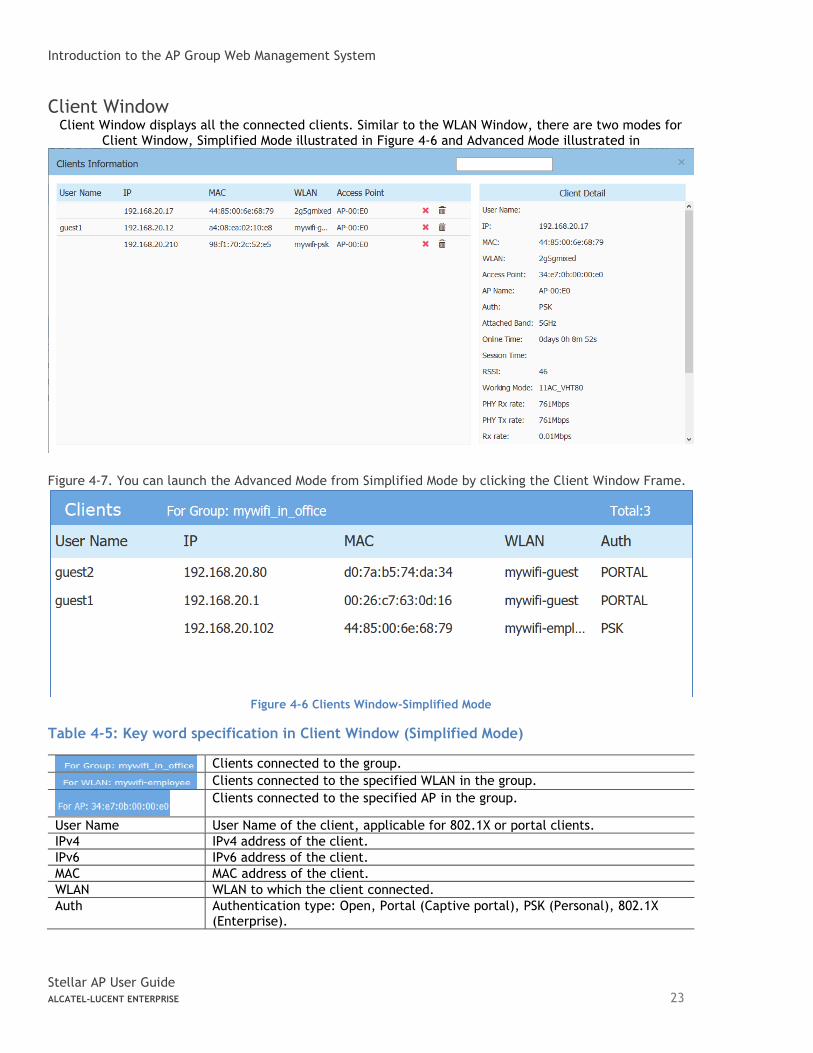
Client Window Client Window displays all the connected clients. Similar to the WLAN Window, there are two modes for
Client Window, Simplified Mode illustrated in Figure 4-6 and Advanced Mode illustrated in
Figure 4-7. You can launch the Advanced Mode from Simplified Mode by clicking the Client Window Frame.
Figure 4-6 Clients Window-Simplified Mode
Table 4-5: Key word specification in Client Window (Simplified Mode)
Clients connected to the group.
Clients connected to the specified WLAN in the group.
Clients connected to the specified AP in the group.
User Name User Name of the client, applicable for 802.1X or portal clients.
IPv4 IPv4 address of the client.
IPv6 IPv6 address of the client.
MAC MAC address of the client.
WLAN WLAN to which the client connected.
Auth Authentication type: Open, Portal (Captive portal), PSK (Personal), 802.1X (Enterprise).
Introduction to the AP Group Web Management System
Stellar AP User Guide ALCATEL-LUCENT ENTERPRISE 24
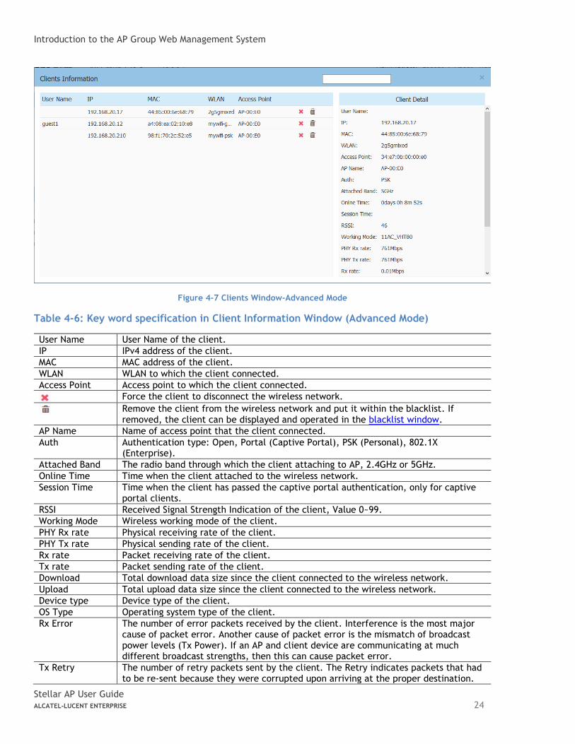
Figure 4-7 Clients Window-Advanced Mode
Table 4-6: Key word specification in Client Information Window (Advanced Mode)
User Name User Name of the client.
IP IPv4 address of the client.
MAC MAC address of the client.
WLAN WLAN to which the client connected.
Access Point Access point to which the client connected.
Force the client to disconnect the wireless network.
Remove the client from the wireless network and put it within the blacklist. If removed, the client can be displayed and operated in the blacklist window.
AP Name Name of access point that the client connected.
Auth Authentication type: Open, Portal (Captive Portal), PSK (Personal), 802.1X (Enterprise).
Attached Band The radio band through which the client attaching to AP, 2.4GHz or 5GHz.
Online Time Time when the client attached to the wireless network.
Session Time Time when the client has passed the captive portal authentication, only for captive portal clients.
RSSI Received Signal Strength Indication of the client, Value 0~99.
Working Mode Wireless working mode of the client.
PHY Rx rate Physical receiving rate of the client.
PHY Tx rate Physical sending rate of the client.
Rx rate Packet receiving rate of the client.
Tx rate Packet sending rate of the client.
Download Total download data size since the client connected to the wireless network.
Upload Total upload data size since the client connected to the wireless network.
Device type Device type of the client.
OS Type Operating system type of the client.
Rx Error The number of error packets received by the client. Interference is the most major cause of packet error. Another cause of packet error is the mismatch of broadcast power levels (Tx Power). If an AP and client device are communicating at much different broadcast strengths, then this can cause packet error.
Tx Retry The number of retry packets sent by the client. The Retry indicates packets that had to be re-sent because they were corrupted upon arriving at the proper destination.
Introduction to the AP Group Web Management System
Stellar AP User Guide ALCATEL-LUCENT ENTERPRISE 25
Roaming History Showing roaming history between SSID/AP/Band for the client, total 32 roaming records can be displayed and will be separated by connection sessions.
• Connection Session – A session represent a period which starting from associating to the wireless network and ending by disassociating. Roaming records are distributed within sessions.
• The connection sessions are arranged based to time sequence. The latest session will be positioned on the top of roaming history display.
• The Offline status represent the connection session has ended. The Online status represent an ongoing session and the client is not disassociated.
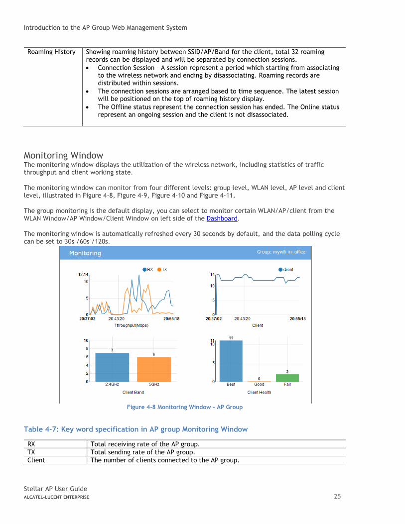
Monitoring Window The monitoring window displays the utilization of the wireless network, including statistics of traffic throughput and client working state. The monitoring window can monitor from four different levels: group level, WLAN level, AP level and client level, illustrated in Figure 4-8, Figure 4-9, Figure 4-10 and Figure 4-11. The group monitoring is the default display, you can select to monitor certain WLAN/AP/client from the WLAN Window/AP Window/Client Window on left side of the Dashboard. The monitoring window is automatically refreshed every 30 seconds by default, and the data polling cycle can be set to 30s /60s /120s.
Figure 4-8 Monitoring Window - AP Group
Table 4-7: Key word specification in AP group Monitoring Window
RX Total receiving rate of the AP group.
TX Total sending rate of the AP group.
Client The number of clients connected to the AP group.
Introduction to the AP Group Web Management System
Stellar AP User Guide ALCATEL-LUCENT ENTERPRISE 26
Client Band The working band distribution of clients connected to the AP group, including number of clients working on 2.4GHz band and number of clients working on 5GHz band.
Client Health The wireless connection quality between client and Stellar AP, it is judged by the signals of client, and classified as below:
• Best— Number of clients whose signal strength is more than 30.
• Good— Number of clients whose signal strength is between 15 ~30.
• Fair—Number of clients whose signal strength is less than 15.
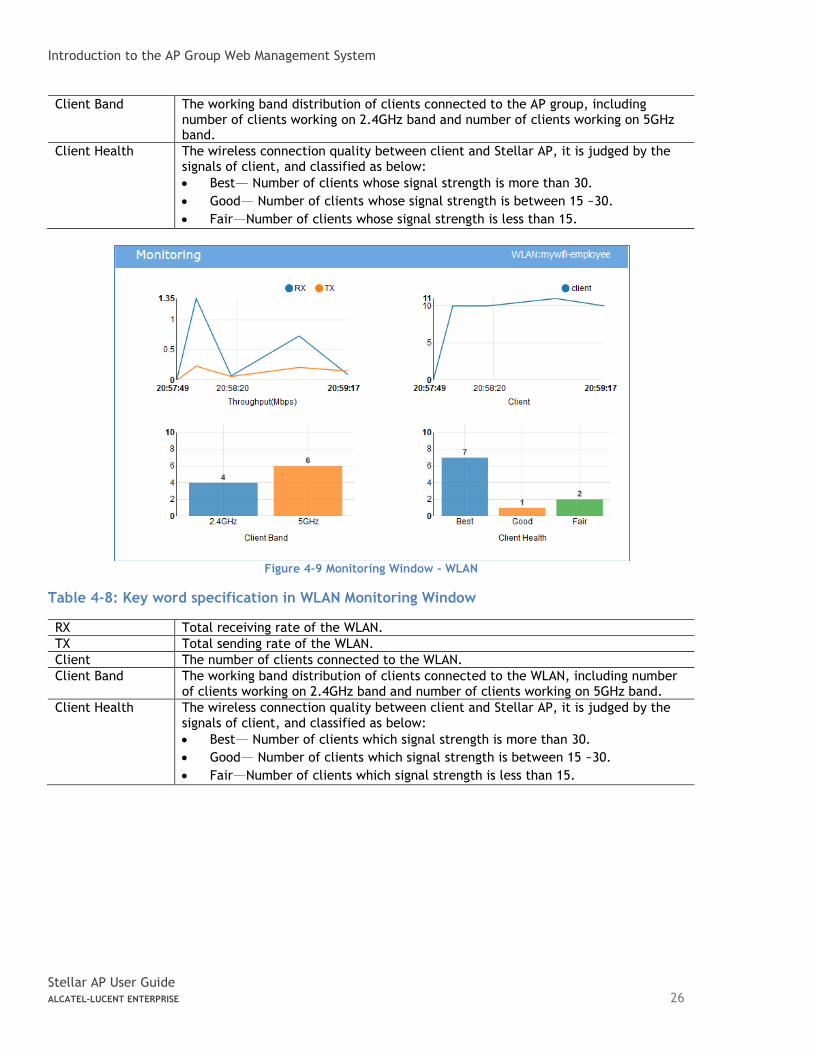
Figure 4-9 Monitoring Window - WLAN
Table 4-8: Key word specification in WLAN Monitoring Window
RX Total receiving rate of the WLAN.
TX Total sending rate of the WLAN.
Client The number of clients connected to the WLAN.
Client Band The working band distribution of clients connected to the WLAN, including number of clients working on 2.4GHz band and number of clients working on 5GHz band.
Client Health The wireless connection quality between client and Stellar AP, it is judged by the signals of client, and classified as below:
• Best— Number of clients which signal strength is more than 30.
• Good— Number of clients which signal strength is between 15 ~30.
• Fair—Number of clients which signal strength is less than 15.
Introduction to the AP Group Web Management System
Stellar AP User Guide ALCATEL-LUCENT ENTERPRISE 27
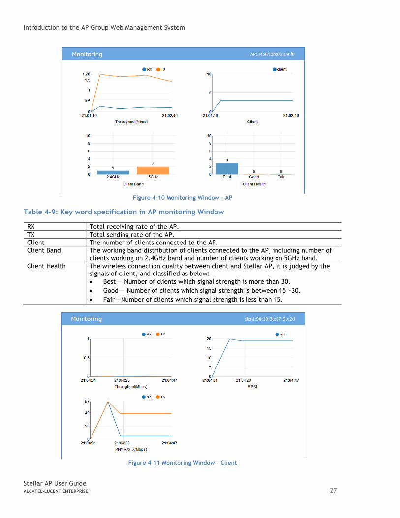
Figure 4-10 Monitoring Window - AP
Table 4-9: Key word specification in AP monitoring Window
RX Total receiving rate of the AP.
TX Total sending rate of the AP.
Client The number of clients connected to the AP.
Client Band The working band distribution of clients connected to the AP, including number of clients working on 2.4GHz band and number of clients working on 5GHz band.
Client Health The wireless connection quality between client and Stellar AP, it is judged by the signals of client, and classified as below:
• Best— Number of clients which signal strength is more than 30.
• Good— Number of clients which signal strength is between 15 ~30.
• Fair—Number of clients which signal strength is less than 15.
Figure 4-11 Monitoring Window - Client
Introduction to the AP Group Web Management System
Stellar AP User Guide ALCATEL-LUCENT ENTERPRISE 28
Table 4-10: Key word specification in Client Monitoring Window
RX Receiving rate of the client.
TX Sending rate of the client.
RSSI Received Signal Strength Indication of the client
PHY RX Physical receiving rate of the client.
PHY TX Physical sending rate of the client.
Note 4-3: The data shown in the monitoring window is collected and displayed while the window is open. The data is not stored and no historical view of the data is available.
System Page
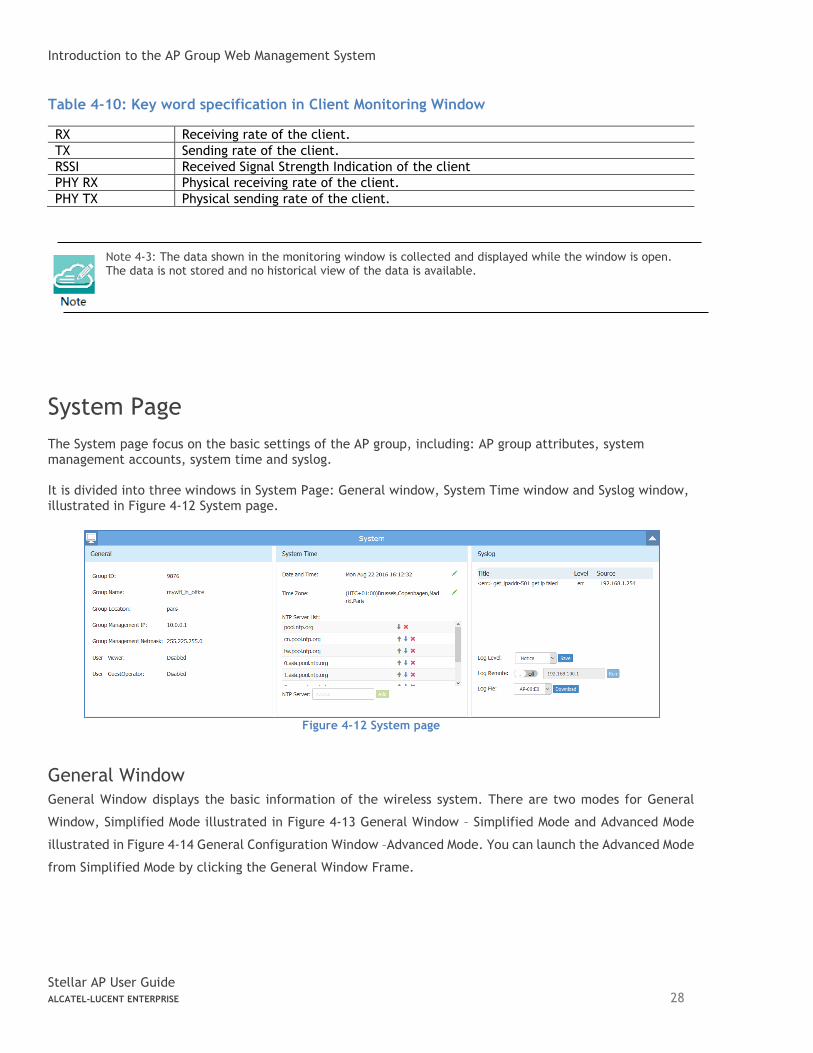
The System page focus on the basic settings of the AP group, including: AP group attributes, system management accounts, system time and syslog. It is divided into three windows in System Page: General window, System Time window and Syslog window, illustrated in Figure 4-12 System page.
Figure 4-12 System page
General Window
General Window displays the basic information of the wireless system. There are two modes for General
Window, Simplified Mode illustrated in Figure 4-13 General Window – Simplified Mode and Advanced Mode
illustrated in Figure 4-14 General Configuration Window –Advanced Mode. You can launch the Advanced Mode
from Simplified Mode by clicking the General Window Frame.
Introduction to the AP Group Web Management System
Stellar AP User Guide ALCATEL-LUCENT ENTERPRISE 29
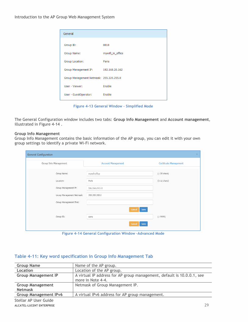
Figure 4-13 General Window – Simplified Mode
The General Configuration window includes two tabs: Group Info Management and Account management, illustrated in Figure 4-14 . Group Info Management Group Info Management contains the basic information of the AP group, you can edit it with your own group settings to identify a private Wi-Fi network.
Figure 4-14 General Configuration Window –Advanced Mode
Table 4-11: Key word specification in Group Info Management Tab
Group Name Name of the AP group.
Location Location of the AP group.
Group Management IP A virtual IP address for AP group management, default is 10.0.0.1, see more in Note 4-4.
Group Management Netmask
Netmask of Group Management IP.
Group Management IPv6 A virtual IPv6 address for AP group management.
Introduction to the AP Group Web Management System
Stellar AP User Guide ALCATEL-LUCENT ENTERPRISE 30
Group ID Identification of the AP group, default is 100.
MQTT Compatibility Enable to allow AP with lower version firmware (AWOS4.0.0 and before) to join. The lower version firmware is low-level security on MQTT. By default, it is not allowed AWOS4.0.0 and before version AP to join.
Note 4-4: AP of a group usually obtains its IP address dynamically from a DCHP server, and it is difficult to
keep the same assigned IP address for the AP. So managing the AP group by the AP’s dynamic IP address can
be difficult. The Group Management IP (GMIP) is a static IP address configured for the AP group web
management, and you can manage the AP group via accessing the URL: http://GMIP:8080 by wired or wireless.
The GMIP is configured on the PVM of the AP group, and you have to make sure the GMIP on the PVM is routable
from your configuring terminal (browser). A recommended method is to choose an idle IP address from the AP
group domain to configure as a GMIP.
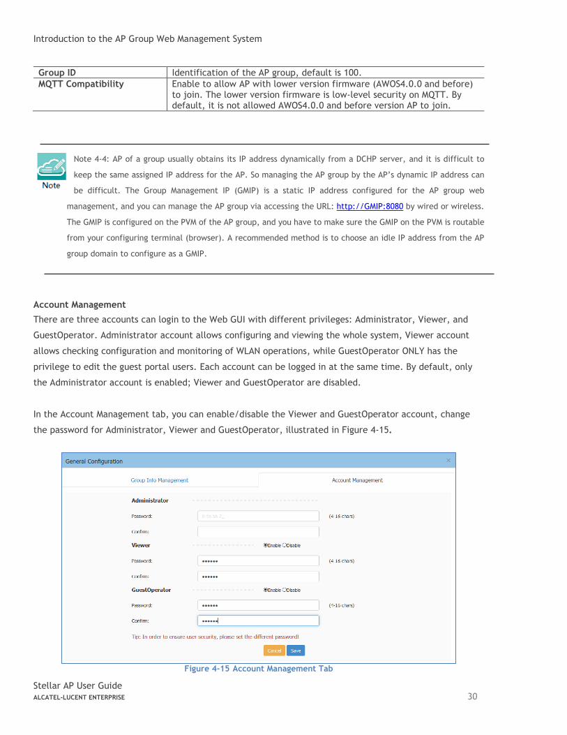
Account Management
There are three accounts can login to the Web GUI with different privileges: Administrator, Viewer, and
GuestOperator. Administrator account allows configuring and viewing the whole system, Viewer account
allows checking configuration and monitoring of WLAN operations, while GuestOperator ONLY has the
privilege to edit the guest portal users. Each account can be logged in at the same time. By default, only
the Administrator account is enabled; Viewer and GuestOperator are disabled.
In the Account Management tab, you can enable/disable the Viewer and GuestOperator account, change
the password for Administrator, Viewer and GuestOperator, illustrated in Figure 4-15.
Figure 4-15 Account Management Tab
Introduction to the AP Group Web Management System
Stellar AP User Guide ALCATEL-LUCENT ENTERPRISE 31
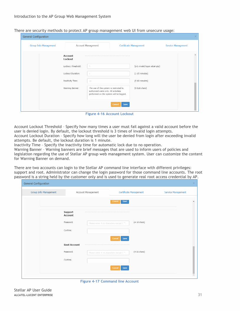
There are security methods to protect AP group management web UI from unsecure usage:
Figure 4-16 Account Lockout
Account Lockout Threshold – Specify how many times a user must fail against a valid account before the user is denied login. By default, the lockout threshold is 3 times of invalid login attempts. Account Lockout Duration – Specify how long will the user be denied from login after exceeding invalid attempts. Be default, the lockout duration is 1 minute. Inactivity Time – Specify the inactivity time for automatic lock due to no operation. Warning Banner – Warning banners are brief messages that are used to inform users of policies and legislation regarding the use of Stellar AP group web management system. User can customize the content for Warning Banner on demand. There are two accounts can login to the Stellar AP command line interface with different privileges: support and root. Administrator can change the login password for those command line accounts. The root password is a string held by the customer only and is used to generate real root access credential by AP.
Figure 4-17 Command line Account
Introduction to the AP Group Web Management System
Stellar AP User Guide ALCATEL-LUCENT ENTERPRISE 32
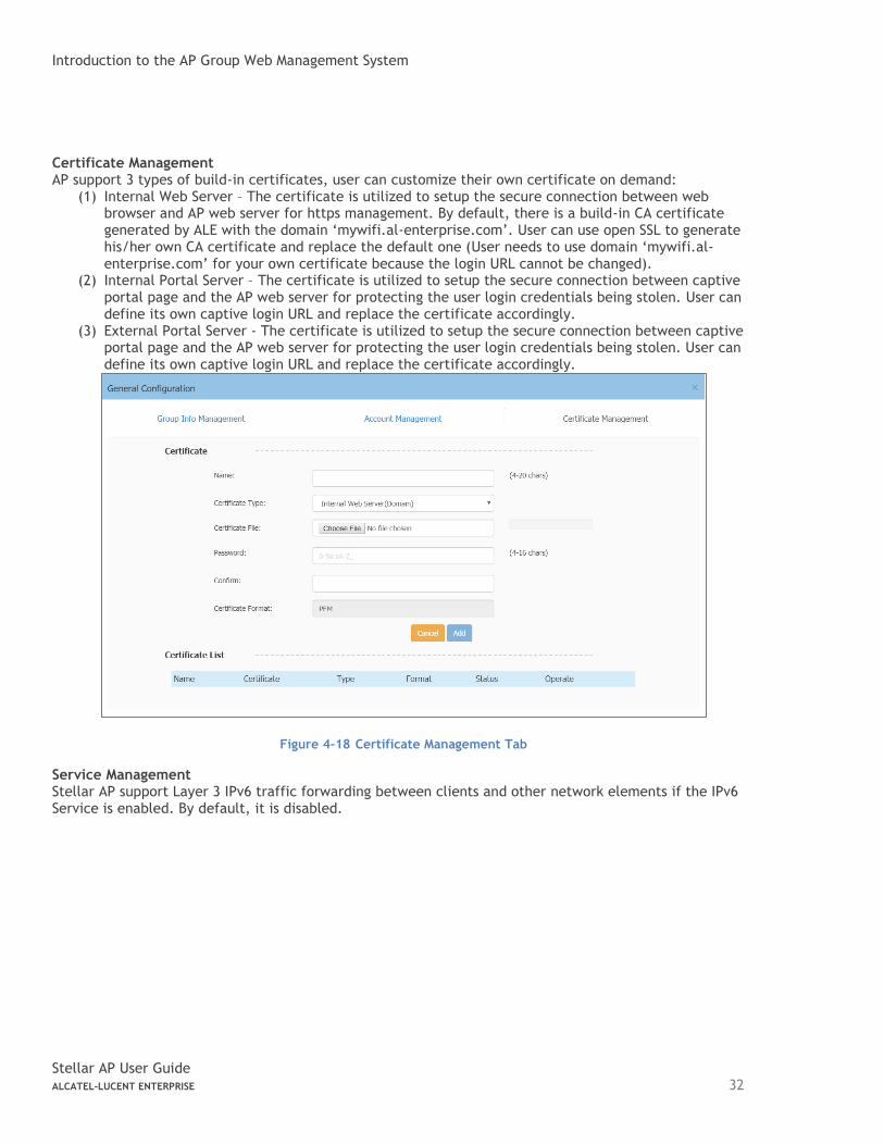
Certificate Management AP support 3 types of build-in certificates, user can customize their own certificate on demand:
(1) Internal Web Server – The certificate is utilized to setup the secure connection between web browser and AP web server for https management. By default, there is a build-in CA certificate generated by ALE with the domain ‘mywifi.al-enterprise.com’. User can use open SSL to generate his/her own CA certificate and replace the default one (User needs to use domain ‘mywifi.al-enterprise.com’ for your own certificate because the login URL cannot be changed).
(2) Internal Portal Server – The certificate is utilized to setup the secure connection between captive portal page and the AP web server for protecting the user login credentials being stolen. User can define its own captive login URL and replace the certificate accordingly.
(3) External Portal Server - The certificate is utilized to setup the secure connection between captive portal page and the AP web server for protecting the user login credentials being stolen. User can define its own captive login URL and replace the certificate accordingly.
Figure 4-18 Certificate Management Tab
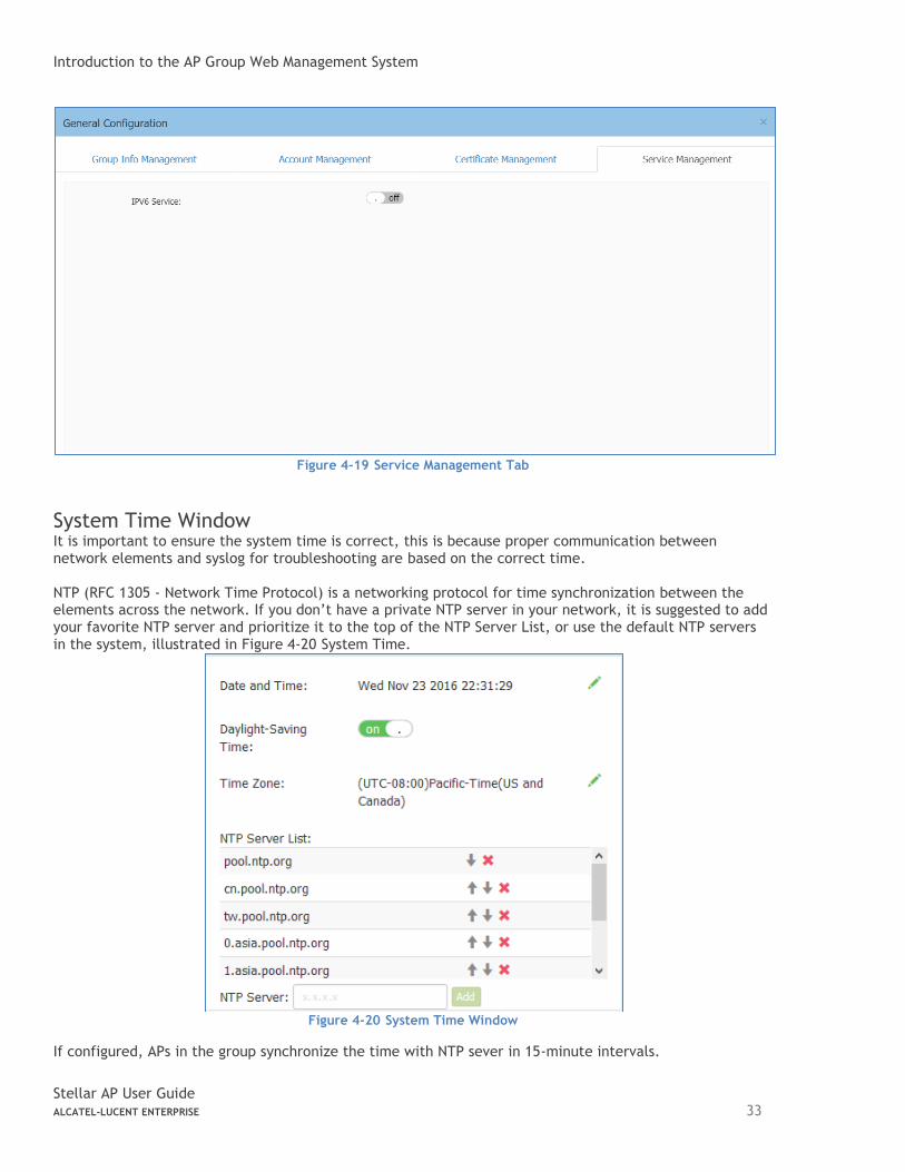
Service Management Stellar AP support Layer 3 IPv6 traffic forwarding between clients and other network elements if the IPv6 Service is enabled. By default, it is disabled.
Introduction to the AP Group Web Management System
Stellar AP User Guide ALCATEL-LUCENT ENTERPRISE 33
Figure 4-19 Service Management Tab
System Time Window It is important to ensure the system time is correct, this is because proper communication between network elements and syslog for troubleshooting are based on the correct time. NTP (RFC 1305 - Network Time Protocol) is a networking protocol for time synchronization between the elements across the network. If you don’t have a private NTP server in your network, it is suggested to add your favorite NTP server and prioritize it to the top of the NTP Server List, or use the default NTP servers in the system, illustrated in Figure 4-20 System Time.
Figure 4-20 System Time Window
If configured, APs in the group synchronize the time with NTP sever in 15-minute intervals.
Introduction to the AP Group Web Management System
Stellar AP User Guide ALCATEL-LUCENT ENTERPRISE 34
You can also specify the Time Zone and daylight-saving time of the AP group to coordinate with the local time. The daylight-saving time is automatically enabled on supporting time zone.
Note 4-5: In order to ensure time synchronization, it is recommended to check the reachability before adding
an NTP server. If the NTP server is not configured or is unreachable, an AP reboot may lead to variation in
time.
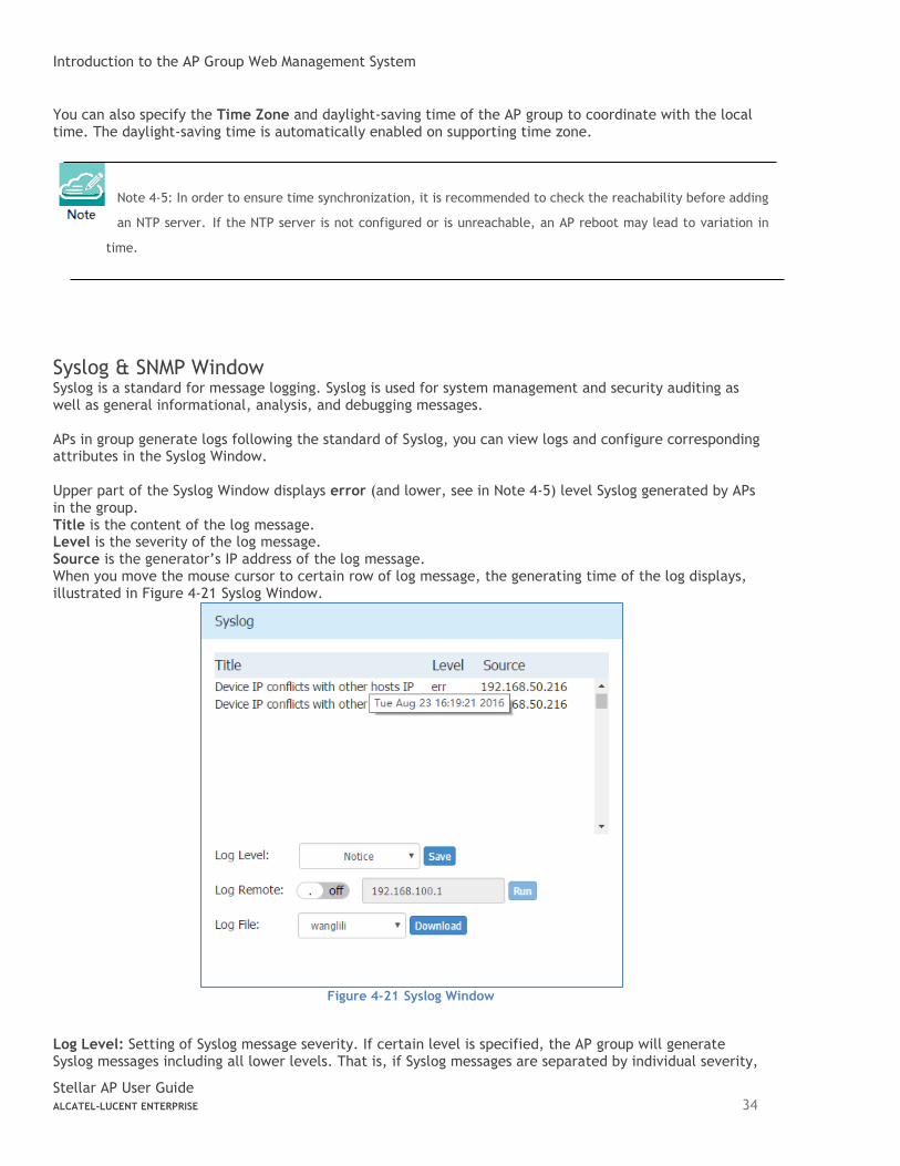
Syslog & SNMP Window Syslog is a standard for message logging. Syslog is used for system management and security auditing as well as general informational, analysis, and debugging messages. APs in group generate logs following the standard of Syslog, you can view logs and configure corresponding attributes in the Syslog Window. Upper part of the Syslog Window displays error (and lower, see in Note 4-5) level Syslog generated by APs in the group. Title is the content of the log message. Level is the severity of the log message. Source is the generator’s IP address of the log message. When you move the mouse cursor to certain row of log message, the generating time of the log displays, illustrated in Figure 4-21 Syslog Window.
Figure 4-21 Syslog Window
Log Level: Setting of Syslog message severity. If certain level is specified, the AP group will generate Syslog messages including all lower levels. That is, if Syslog messages are separated by individual severity,
Introduction to the AP Group Web Management System
Stellar AP User Guide ALCATEL-LUCENT ENTERPRISE 35
a Warning level entry will also be included in Notice, Info and Debug processing. Notice is the default level of Syslog setting, and the system generates logs including levels of Notice, Warning, Error, Critical, Alert and Emergency. Log Remote: Setting of remote log server. If configured and enabled, besides storage in local file, Syslog messages of all APs in group can be sent to and stored in the server once generated. Log File: Download the log file on a selected AP in the group to your configuring machine. Syslog messages are stored in a local file when generated. For one AP, up to 1MB size of syslog messages can be saved in the local log file. The log file is FIFO, new syslog messages will replace the old ones if the size exceeds 1MB.
Note 4-5: Syslog is divided into eight levels, and lowest level 0 is Emergency severity while highest level 7 is
Debug severity. Definition of Syslog severity as follow:
Level Value Severity Keyword Description
0 Emergency emerg System is unusable
1 Alert alert Should be corrected immediately
2 Critical crit Critical conditions
3 Error err Error conditions
4 Warning warning May indicate that an error will occur if action is not taken
5 Notice notice Events that are unusual, but not error conditions
6 Informational info Normal operational messages that require no action
7 Debug debug Information useful to developers for debugging
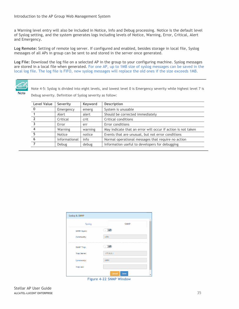
Figure 4-22 SNMP Window
Introduction to the AP Group Web Management System
Stellar AP User Guide ALCATEL-LUCENT ENTERPRISE 36
With SNMP user can monitor AP status in the group through traditional network management platform.
• SNMP Agent – Enable/Disable the SNMP agent on AP. Network management platform can fetch information from AP through SNMP protocol.
• Community – The credential used to communicate between AP and network management platform.
• SNMP Trap – Enable/Disable AP to send trap to network management platform.
• Trap Server – Network management platform to which AP send SNMP traps.
• Trap List – Specify the trap items needs to be sent to network management platform.
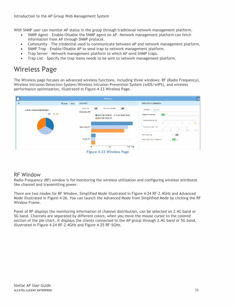
Wireless Page
The Wireless page focuses on advanced wireless functions, including three windows: RF (Radio Frequency), Wireless Intrusion Detection System/Wireless Intrusion Prevention System (wIDS/wIPS), and wireless performance optimization, illustrated in Figure 4-23 Wireless Page.
Figure 4-23 Wireless Page
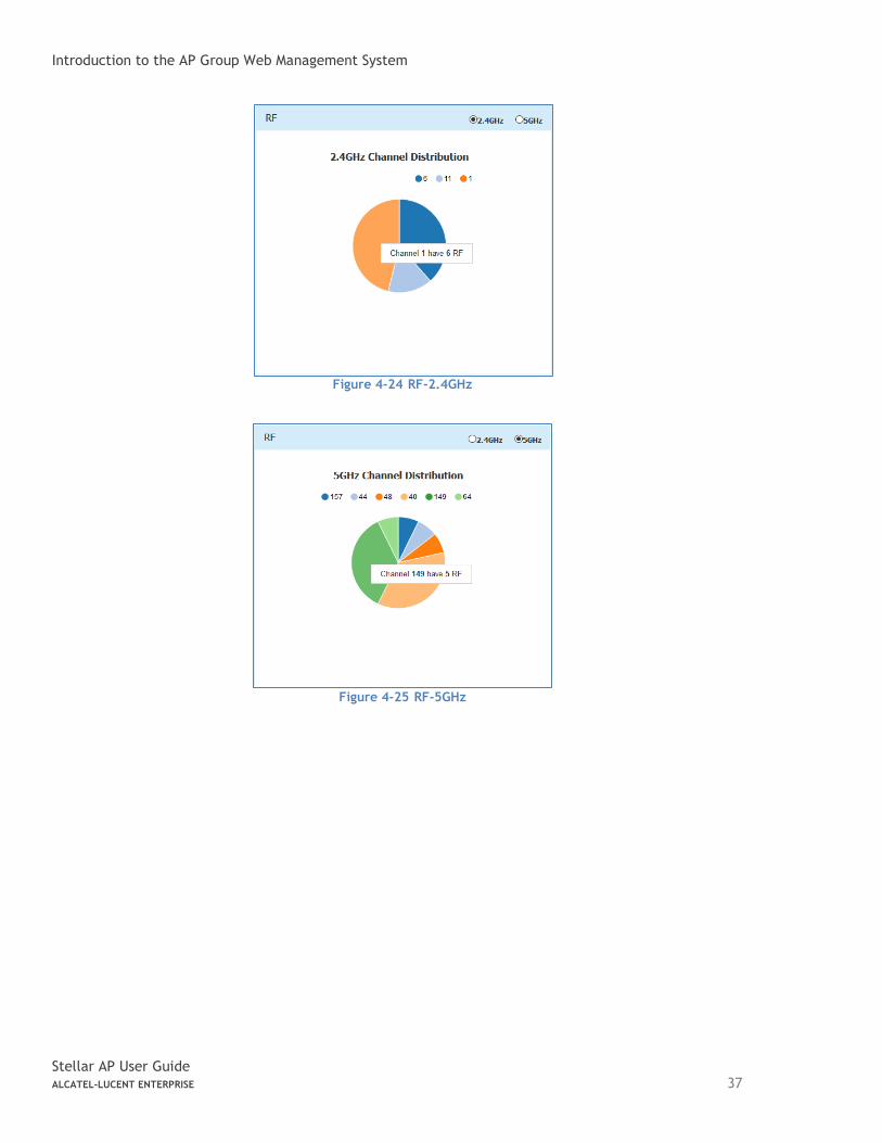
RF Window Radio Frequency (RF) window is for monitoring the wireless utilization and configuring wireless attributes like channel and transmitting power. There are two modes for RF Window, Simplified Mode illustrated in Figure 4-24 RF-2.4GHz and Advanced Mode illustrated in Figure 4-26. You can launch the Advanced Mode from Simplified Mode by clicking the RF Window Frame. Panel of RF displays the monitoring information of channel distribution, can be selected on 2.4G band or 5G band. Channels are separated by different colors, when you move the mouse cursor to the colored section of the pie chart, it displays the clients connected to the AP group through 2.4G band or 5G band, illustrated in Figure 4-24 RF-2.4GHz and Figure 4-25 RF-5GHz.
Introduction to the AP Group Web Management System
Stellar AP User Guide ALCATEL-LUCENT ENTERPRISE 37
Figure 4-24 RF-2.4GHz
Figure 4-25 RF-5GHz
Introduction to the AP Group Web Management System
Stellar AP User Guide ALCATEL-LUCENT ENTERPRISE 38
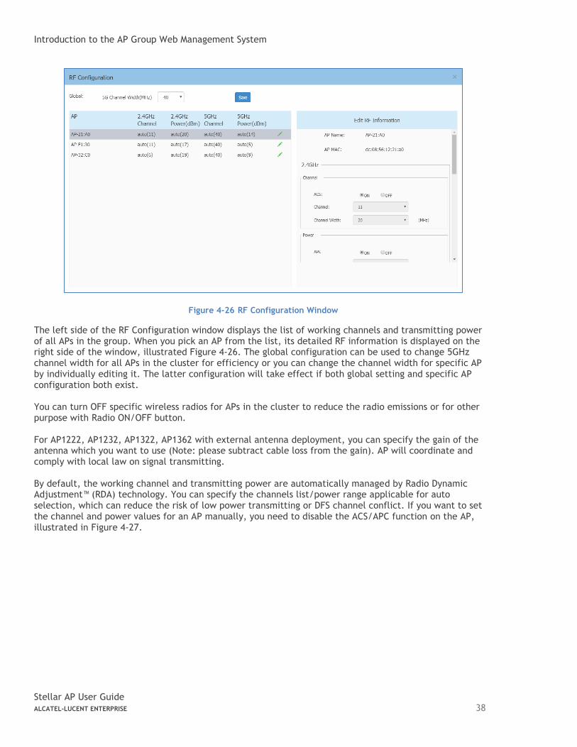
Figure 4-26 RF Configuration Window
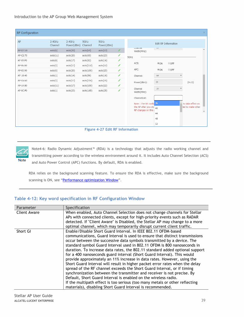
The left side of the RF Configuration window displays the list of working channels and transmitting power of all APs in the group. When you pick an AP from the list, its detailed RF information is displayed on the right side of the window, illustrated Figure 4-26. The global configuration can be used to change 5GHz channel width for all APs in the cluster for efficiency or you can change the channel width for specific AP by individually editing it. The latter configuration will take effect if both global setting and specific AP configuration both exist. You can turn OFF specific wireless radios for APs in the cluster to reduce the radio emissions or for other purpose with Radio ON/OFF button. For AP1222, AP1232, AP1322, AP1362 with external antenna deployment, you can specify the gain of the antenna which you want to use (Note: please subtract cable loss from the gain). AP will coordinate and comply with local law on signal transmitting. By default, the working channel and transmitting power are automatically managed by Radio Dynamic Adjustment™ (RDA) technology. You can specify the channels list/power range applicable for auto selection, which can reduce the risk of low power transmitting or DFS channel conflict. If you want to set the channel and power values for an AP manually, you need to disable the ACS/APC function on the AP, illustrated in Figure 4-27.
Introduction to the AP Group Web Management System
Stellar AP User Guide ALCATEL-LUCENT ENTERPRISE 39
Figure 4-27 Edit RF Information
Note4-6: Radio Dynamic Adjustment™ (RDA) is a technology that adjusts the radio working channel and
transmitting power according to the wireless environment around it. It includes Auto Channel Selection (ACS)
and Auto Power Control (APC) functions. By default, RDA is enabled.
RDA relies on the background scanning feature. To ensure the RDA is effective, make sure the background
scanning is ON, see “Performance optimization Window”.
Table 4-12: Key word specification in RF Configuration Window
Parameter Specification
Client Aware When enabled, Auto Channel Selection does not change channels for Stellar APs with connected clients, except for high-priority events such as RADAR detected. If "Client Aware" is Disabled, the Stellar AP may change to a more optimal channel, which may temporarily disrupt current client traffic.
Short GI Enable/Disable Short Guard Interval. In IEEE 802.11 OFDM-based communications, Guard Interval is used to ensure that distinct transmissions occur between the successive data symbols transmitted by a device. The standard symbol Guard Interval used in 802.11 OFDM is 800 nanoseconds in duration. To increase data rates, the 802.11 standard added optional support for a 400 nanoseconds guard interval (Short Guard Interval). This would provide approximately an 11% increase in data rates. However, using the Short Guard Interval will result in higher packet error rates when the delay spread of the RF channel exceeds the Short Guard Interval, or if timing synchronization between the transmitter and receiver is not precise. By Default, Short Guard Interval is enabled on the wireless radio. If the multipath effect is too serious (too many metals or other reflecting materials), disabling Short Guard Interval is recommended.
Introduction to the AP Group Web Management System
Stellar AP User Guide ALCATEL-LUCENT ENTERPRISE 40
MU-MIMO Enable/Disable MU-MIMO (multi-user, multiple-input, multiple-output) feature.
High Efficiency Enable/Disable 802.11ax high efficiency wireless functionality. When disabled, the HE mode capable AP will downgrade to VHT (Very High Throughput) mode.
Beacon Interval Specify the Beacon period for the AP in milliseconds. This indicates how often the 802.11 beacon management frames are transmitted by the access point. You can specify a value within the range of 60-500. The default value is 100 milliseconds.
wIDS/wIPS Window wIDS/wIPS window focus on the wireless security of the Stellar AP network. Wireless is a borderless network and always works in an open environment which can be interfered with and attacked. It is useful to discover the surrounding wireless conditions, and based on that, provide instructions and tools to help administrators improve the quality of the wireless network. Usually there are two types of foreign unknown APs having a negative effect on the wireless network, they are interfering APs and rogue APs. An interfering AP is an AP seen in the wireless environment but not connected to the wired network. The interfering AP can provide RF interference potentially, however, it is not considered a direct security threat, because it is not connected to the wired network. A rogue AP is an unauthorized AP plugged into the wired side of the network or a foreign interfering AP broadcasting the same SSID with the AP group. A rogue AP is considered a security threat to the AP group. Panel of wIDS/wIPS displays top 5 Stellar APs with interference from surrounding APs, and the top 5 Stellar APs with the most rogue APs surrounding, illustrated in Figure 4-28.
Figure 4-28 Top 5 AP interfered
AP whitelist: Both interfering APs and rogue APs are foreign unknown APs which can be found by background scanning and are listed in the unknown AP table, illustrated in Figure 4-29. However, some foreign APs found are trusted APs, those are not suitable for being classified as interfering APs or rogue APs. To avoid trusted foreign APs from being classified as interfering APs or rogue APs, you can add the trusted MAC address or MAC prefix to the AP whitelist, illustrated in Figure 4-30. If a foreign AP MAC address is added to the whitelist, it will not be displayed in the unknown AP list.
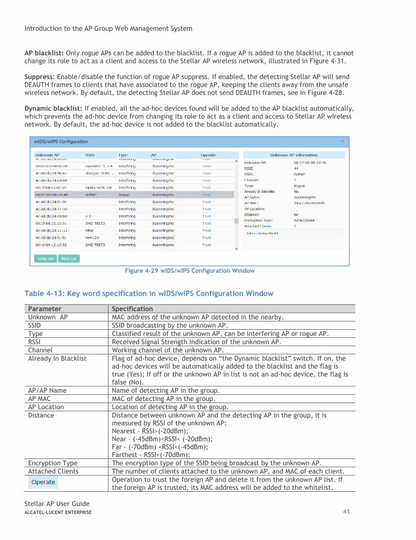
Introduction to the AP Group Web Management System
Stellar AP User Guide ALCATEL-LUCENT ENTERPRISE 41
AP blacklist: Only rogue APs can be added to the blacklist. If a rogue AP is added to the blacklist, it cannot change its role to act as a client and access to the Stellar AP wireless network, illustrated in Figure 4-31. Suppress: Enable/disable the function of rogue AP suppress. If enabled, the detecting Stellar AP will send DEAUTH frames to clients that have associated to the rogue AP, keeping the clients away from the unsafe wireless network. By default, the detecting Stellar AP does not send DEAUTH frames, see in Figure 4-28. Dynamic blacklist: If enabled, all the ad-hoc devices found will be added to the AP blacklist automatically, which prevents the ad-hoc device from changing its role to act as a client and access to Stellar AP wireless network. By default, the ad-hoc device is not added to the blacklist automatically.
Figure 4-29 wIDS/wIPS Configuration Window
Table 4-13: Key word specification in wIDS/wIPS Configuration Window
Parameter Specification
Unknown AP MAC address of the unknown AP detected in the nearby.
SSID SSID broadcasting by the unknown AP.
Type Classified result of the unknown AP, can be interfering AP or rogue AP.
RSSI Received Signal Strength Indication of the unknown AP.
Channel Working channel of the unknown AP.
Already In Blacklist Flag of ad-hoc device, depends on “the Dynamic blacklist” switch. If on, the ad-hoc devices will be automatically added to the blacklist and the flag is true (Yes); If off or the unknown AP in list is not an ad-hoc device, the flag is false (No).
AP/AP Name Name of detecting AP in the group.
AP MAC MAC of detecting AP in the group.
AP Location Location of detecting AP in the group.
Distance Distance between unknown AP and the detecting AP in the group, it is measured by RSSI of the unknown AP: Nearest – RSSI>(-20dBm); Near – (-45dBm)<RSSI< (-20dBm); Far - (-70dBm) <RSSI<(-45dBm); Farthest - RSSI<(-70dBm);
Encryption Type The encryption type of the SSID being broadcast by the unknown AP.
Attached Clients The number of clients attached to the unknown AP, and MAC of each client.
Operation to trust the foreign AP and delete it from the unknown AP list. If the foreign AP is trusted, its MAC address will be added to the whitelist.
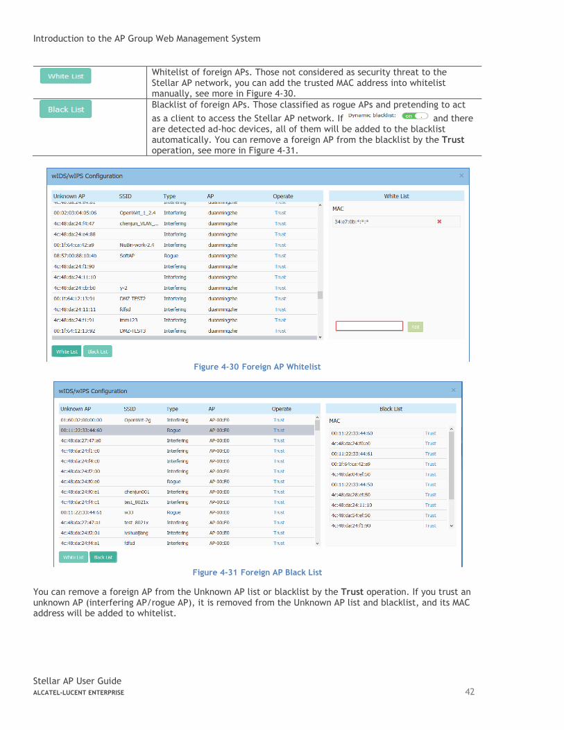
Introduction to the AP Group Web Management System
Stellar AP User Guide ALCATEL-LUCENT ENTERPRISE 42
Whitelist of foreign APs. Those not considered as security threat to the Stellar AP network, you can add the trusted MAC address into whitelist manually, see more in Figure 4-30.
Blacklist of foreign APs. Those classified as rogue APs and pretending to act
as a client to access the Stellar AP network. If and there are detected ad-hoc devices, all of them will be added to the blacklist automatically. You can remove a foreign AP from the blacklist by the Trust operation, see more in Figure 4-31.
Figure 4-30 Foreign AP Whitelist
Figure 4-31 Foreign AP Black List
You can remove a foreign AP from the Unknown AP list or blacklist by the Trust operation. If you trust an unknown AP (interfering AP/rogue AP), it is removed from the Unknown AP list and blacklist, and its MAC address will be added to whitelist.
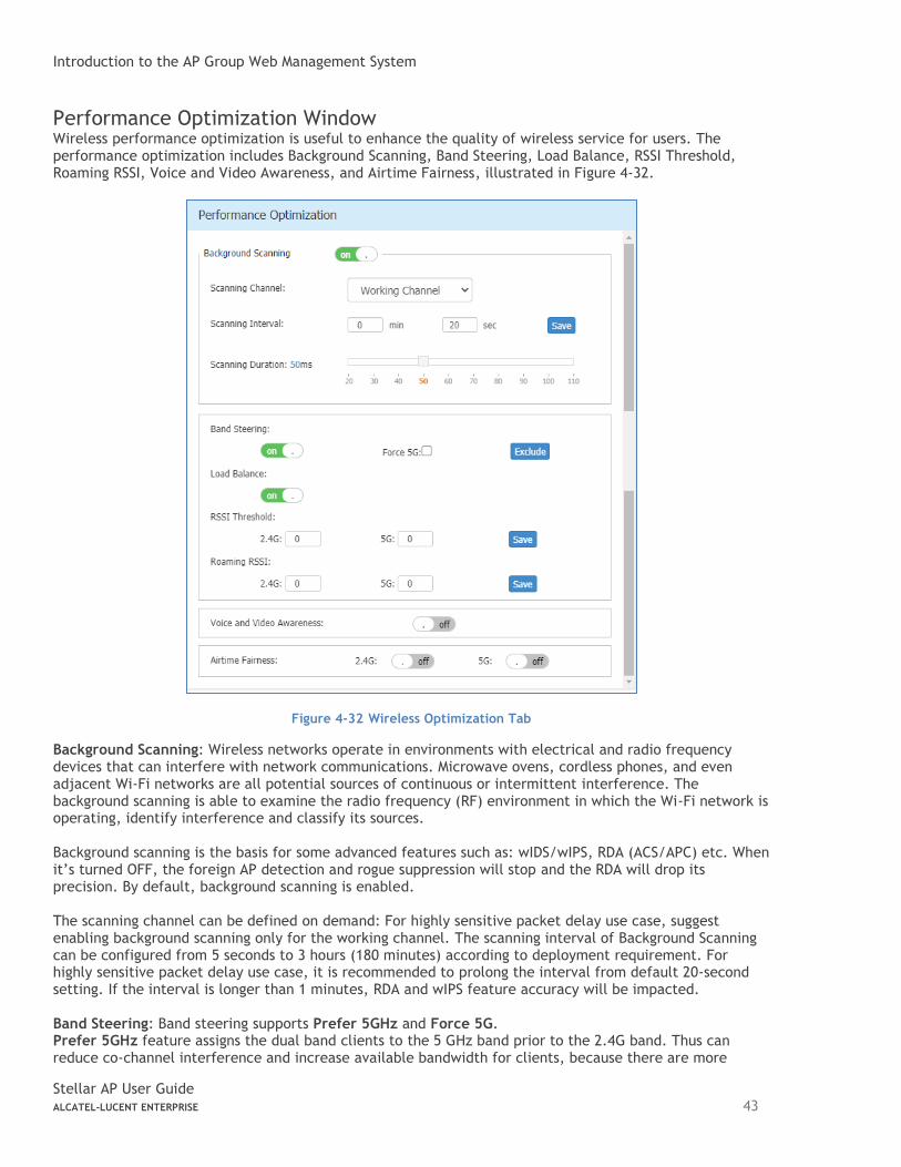
Introduction to the AP Group Web Management System
Stellar AP User Guide ALCATEL-LUCENT ENTERPRISE 43
Performance Optimization Window Wireless performance optimization is useful to enhance the quality of wireless service for users. The performance optimization includes Background Scanning, Band Steering, Load Balance, RSSI Threshold, Roaming RSSI, Voice and Video Awareness, and Airtime Fairness, illustrated in Figure 4-32.
Figure 4-32 Wireless Optimization Tab
Background Scanning: Wireless networks operate in environments with electrical and radio frequency devices that can interfere with network communications. Microwave ovens, cordless phones, and even adjacent Wi-Fi networks are all potential sources of continuous or intermittent interference. The background scanning is able to examine the radio frequency (RF) environment in which the Wi-Fi network is operating, identify interference and classify its sources. Background scanning is the basis for some advanced features such as: wIDS/wIPS, RDA (ACS/APC) etc. When it’s turned OFF, the foreign AP detection and rogue suppression will stop and the RDA will drop its precision. By default, background scanning is enabled. The scanning channel can be defined on demand: For highly sensitive packet delay use case, suggest enabling background scanning only for the working channel. The scanning interval of Background Scanning can be configured from 5 seconds to 3 hours (180 minutes) according to deployment requirement. For highly sensitive packet delay use case, it is recommended to prolong the interval from default 20-second setting. If the interval is longer than 1 minutes, RDA and wIPS feature accuracy will be impacted. Band Steering: Band steering supports Prefer 5GHz and Force 5G. Prefer 5GHz feature assigns the dual band clients to the 5 GHz band prior to the 2.4G band. Thus can reduce co-channel interference and increase available bandwidth for clients, because there are more
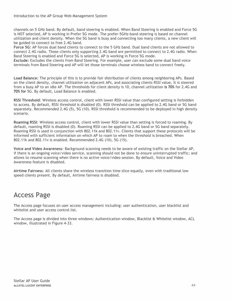
Introduction to the AP Group Web Management System
Stellar AP User Guide ALCATEL-LUCENT ENTERPRISE 44
channels on 5 GHz band. By default, band steering is enabled. When Band Steering is enabled and Force 5G is NOT selected, AP is working in Prefer 5G mode. The prefer-5GHz-band-steering is based on channel utilization and client density. When the 5G band is busy and connecting too many clients, a new client will be guided to connect to free 2.4G band. Force 5G: AP forces dual band clients to connect to the 5 GHz band. Dual band clients are not allowed to connect 2.4G radio. Those clients only supporting 2.4G band are permitted to connect to 2.4G radio. When Band Steering is enabled and Force 5G is selected, AP is working in Force 5G mode. Exclude: Excludes the clients from Band Steering. For example, user can exclude some dual band voice terminals from Band Steering and AP will let those terminals choose wireless band to connect freely. Load Balance: The principle of this is to provide fair distribution of clients among neighboring APs. Based on the client density, channel utilization on adjacent APs, and associating clients RSSI value, it is steered from a busy AP to an idle AP. The thresholds for client density is 10, channel utilization is 70% for 2.4G and 70% for 5G. By default, Load Balance is enabled. RSSI Threshold: Wireless access control, client with lower RSSI value than configured setting is forbidden to access. By default, RSSI threshold is disabled (0). RSSI threshold can be applied to 2.4G band or 5G band separately. Recommended 2.4G (5), 5G (10). RSSI threshold is recommended to be deployed in high density scenario. Roaming RSSI: Wireless access control, client with lower RSSI value than setting is forced to roaming. By default, roaming RSSI is disabled (0). Roaming RSSI can be applied to 2.4G band or 5G band separately. Roaming RSSI is used in conjunction with 802.11k and 802.11v. Clients that support these protocols will be informed with sufficient information on which AP to roam to when the threshold is breached. When 802.11k and 802.11v is enabled. Recommended 2.4G (10), 5G (15). Voice and Video Awareness: Background scanning needs to be aware of existing traffic on the Stellar AP, if there is an ongoing voice/video service, scanning should not be done to ensure uninterrupted traffic; and allows to resume scanning when there is no active voice/video session. By default, Voice and Video Awareness feature is disabled. Airtime Fairness: All clients share the wireless transition time slice equally, even with traditional low speed clients present. By default, Airtime fairness is disabled.
Access Page
The Access page focuses on user access management including: user authentication, user blacklist and whitelist and user access control list. The Access page is divided into three windows: Authentication window, Blacklist & Whitelist window, ACL window, illustrated in Figure 4-33.
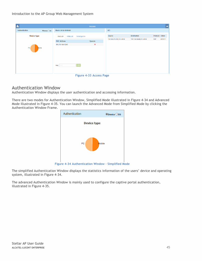
Introduction to the AP Group Web Management System
Stellar AP User Guide ALCATEL-LUCENT ENTERPRISE 45
Figure 4-33 Access Page
Authentication Window Authentication Window displays the user authentication and accessing information. There are two modes for Authentication Window, Simplified Mode illustrated in Figure 4-34 and Advanced Mode illustrated in Figure 4-35. You can launch the Advanced Mode from Simplified Mode by clicking the Authentication Window Frame.
Figure 4-34 Authentication Window – Simplified Mode
The simplified Authentication Window displays the statistics information of the users’ device and operating system, illustrated in Figure 4-34. The advanced Authentication Window is mainly used to configure the captive portal authentication, illustrated in Figure 4-35.
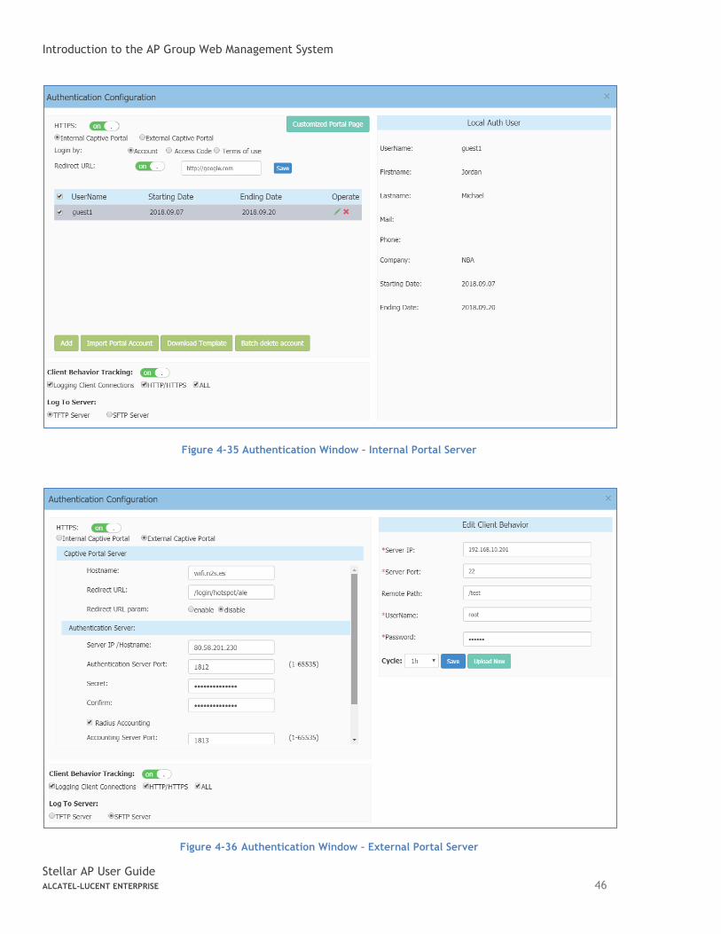
Introduction to the AP Group Web Management System
Stellar AP User Guide ALCATEL-LUCENT ENTERPRISE 46
Figure 4-35 Authentication Window – Internal Portal Server
Figure 4-36 Authentication Window – External Portal Server
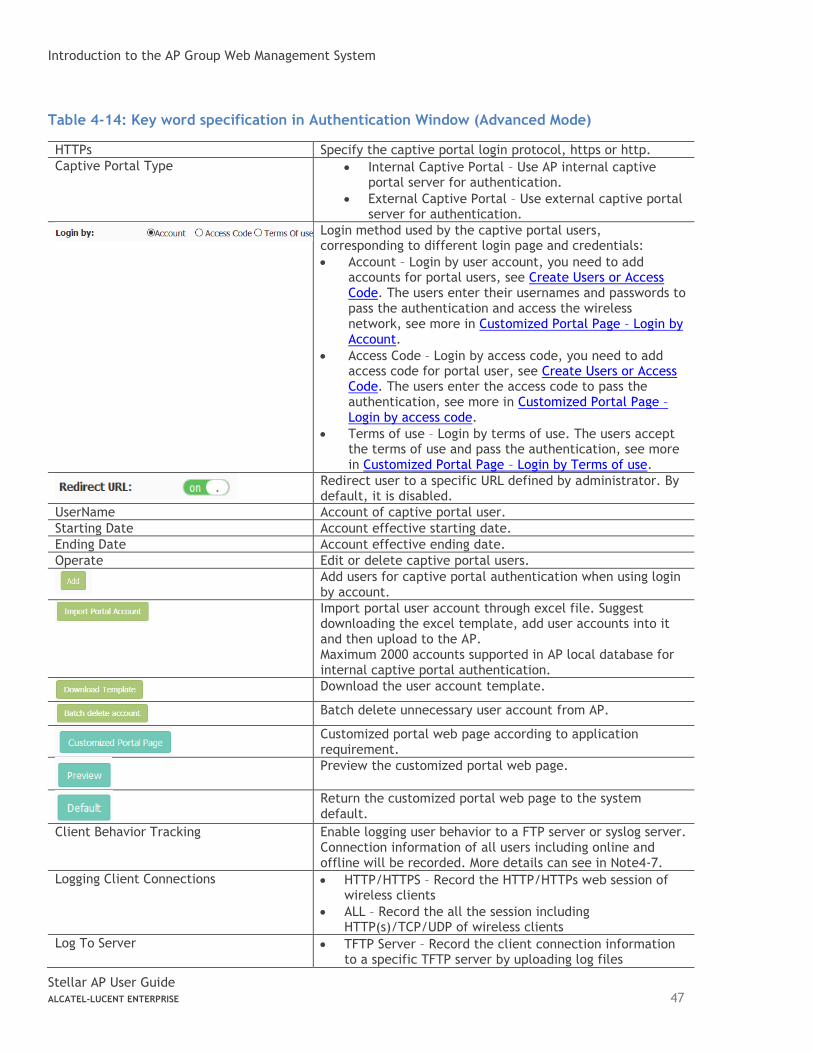
Introduction to the AP Group Web Management System
Stellar AP User Guide ALCATEL-LUCENT ENTERPRISE 47
Table 4-14: Key word specification in Authentication Window (Advanced Mode)
HTTPs Specify the captive portal login protocol, https or http.
Captive Portal Type • Internal Captive Portal – Use AP internal captive portal server for authentication.
• External Captive Portal – Use external captive portal server for authentication.
Login method used by the captive portal users, corresponding to different login page and credentials:
• Account – Login by user account, you need to add accounts for portal users, see Create Users or Access Code. The users enter their usernames and passwords to pass the authentication and access the wireless network, see more in Customized Portal Page – Login by Account.
• Access Code – Login by access code, you need to add access code for portal user, see Create Users or Access Code. The users enter the access code to pass the authentication, see more in Customized Portal Page – Login by access code.
• Terms of use – Login by terms of use. The users accept the terms of use and pass the authentication, see more in Customized Portal Page – Login by Terms of use.
Redirect user to a specific URL defined by administrator. By default, it is disabled.
UserName Account of captive portal user.
Starting Date Account effective starting date.
Ending Date Account effective ending date.
Operate Edit or delete captive portal users.
Add users for captive portal authentication when using login by account.
Import portal user account through excel file. Suggest downloading the excel template, add user accounts into it and then upload to the AP. Maximum 2000 accounts supported in AP local database for internal captive portal authentication.
Download the user account template.
Batch delete unnecessary user account from AP.
Customized portal web page according to application requirement.
Preview the customized portal web page.
Return the customized portal web page to the system default.
Client Behavior Tracking Enable logging user behavior to a FTP server or syslog server. Connection information of all users including online and offline will be recorded. More details can see in Note4-7.
Logging Client Connections • HTTP/HTTPS – Record the HTTP/HTTPs web session of wireless clients
• ALL – Record the all the session including HTTP(s)/TCP/UDP of wireless clients
Log To Server • TFTP Server – Record the client connection information to a specific TFTP server by uploading log files
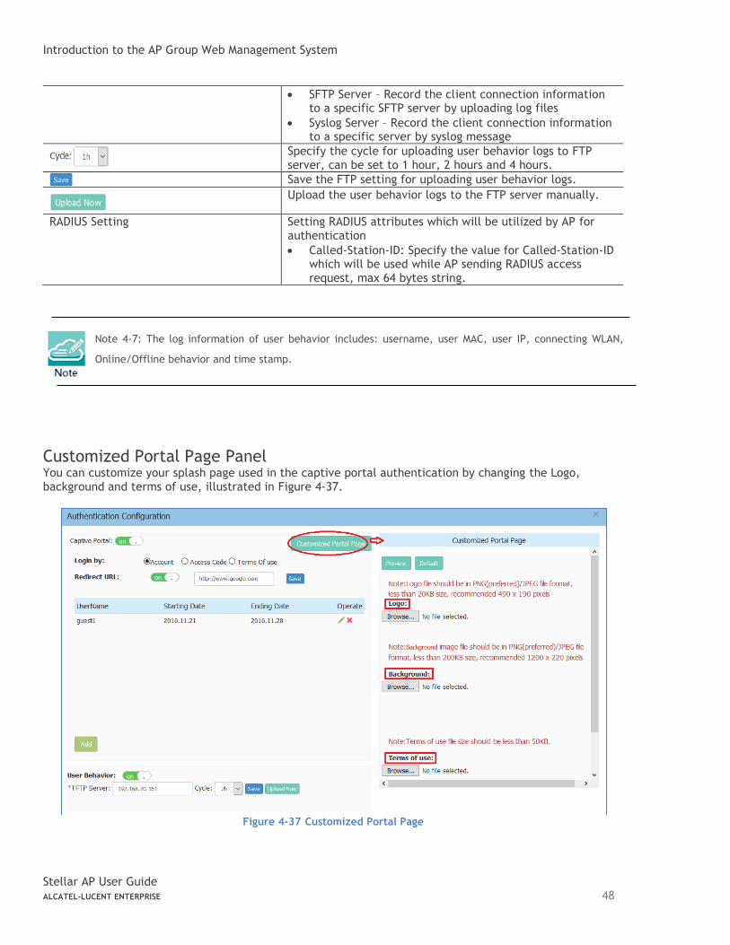
Introduction to the AP Group Web Management System
Stellar AP User Guide ALCATEL-LUCENT ENTERPRISE 48
• SFTP Server – Record the client connection information to a specific SFTP server by uploading log files
• Syslog Server – Record the client connection information to a specific server by syslog message
Specify the cycle for uploading user behavior logs to FTP server, can be set to 1 hour, 2 hours and 4 hours.
Save the FTP setting for uploading user behavior logs.
Upload the user behavior logs to the FTP server manually.
RADIUS Setting Setting RADIUS attributes which will be utilized by AP for authentication
• Called-Station-ID: Specify the value for Called-Station-ID which will be used while AP sending RADIUS access request, max 64 bytes string.
Note 4-7: The log information of user behavior includes: username, user MAC, user IP, connecting WLAN,
Online/Offline behavior and time stamp.
Customized Portal Page Panel You can customize your splash page used in the captive portal authentication by changing the Logo, background and terms of use, illustrated in Figure 4-37.
Figure 4-37 Customized Portal Page
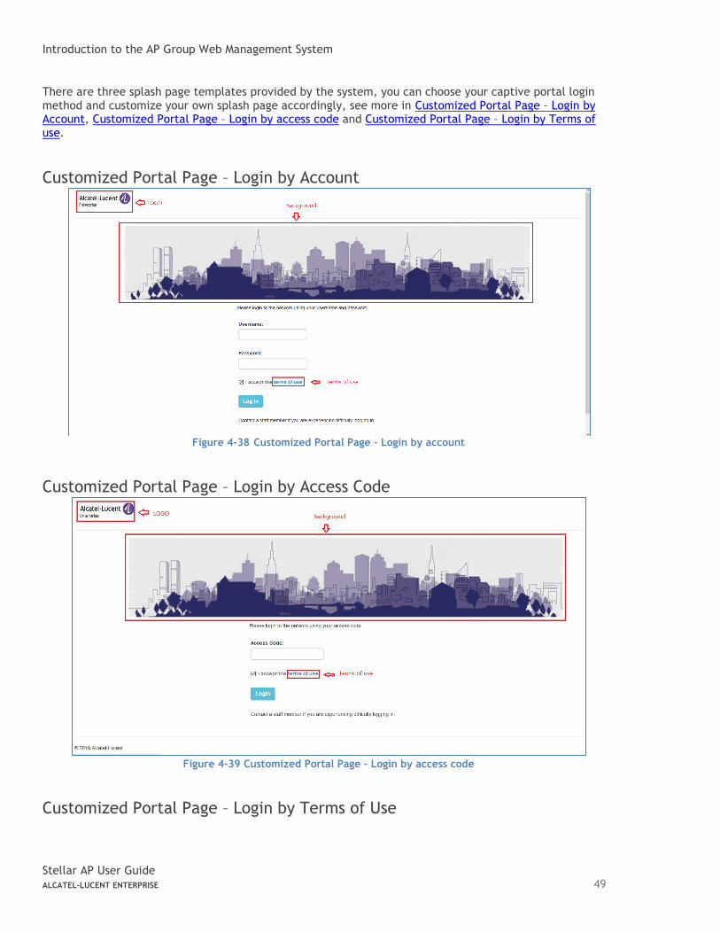
Introduction to the AP Group Web Management System
Stellar AP User Guide ALCATEL-LUCENT ENTERPRISE 49
There are three splash page templates provided by the system, you can choose your captive portal login method and customize your own splash page accordingly, see more in Customized Portal Page – Login by Account, Customized Portal Page – Login by access code and Customized Portal Page – Login by Terms of use.
Customized Portal Page – Login by Account
Figure 4-38 Customized Portal Page – Login by account
Customized Portal Page – Login by Access Code
Figure 4-39 Customized Portal Page – Login by access code
Customized Portal Page – Login by Terms of Use
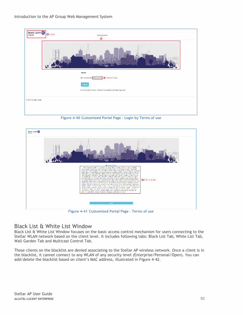
Introduction to the AP Group Web Management System
Stellar AP User Guide ALCATEL-LUCENT ENTERPRISE 50
Figure 4-40 Customized Portal Page – Login by Terms of use
Figure 4-41 Customized Portal Page – Terms of use
Black List & White List Window Black List & White List Window focuses on the basic access control mechanism for users connecting to the Stellar WLAN network based on the client level. It includes following tabs: Black List Tab, White List Tab, Wall Garden Tab and Multicast Control Tab. Those clients on the blacklist are denied associating to the Stellar AP wireless network. Once a client is in the blacklist, it cannot connect to any WLAN of any security level (Enterprise/Personal/Open). You can add/delete the blacklist based on client’s MAC address, illustrated in Figure 4-42.
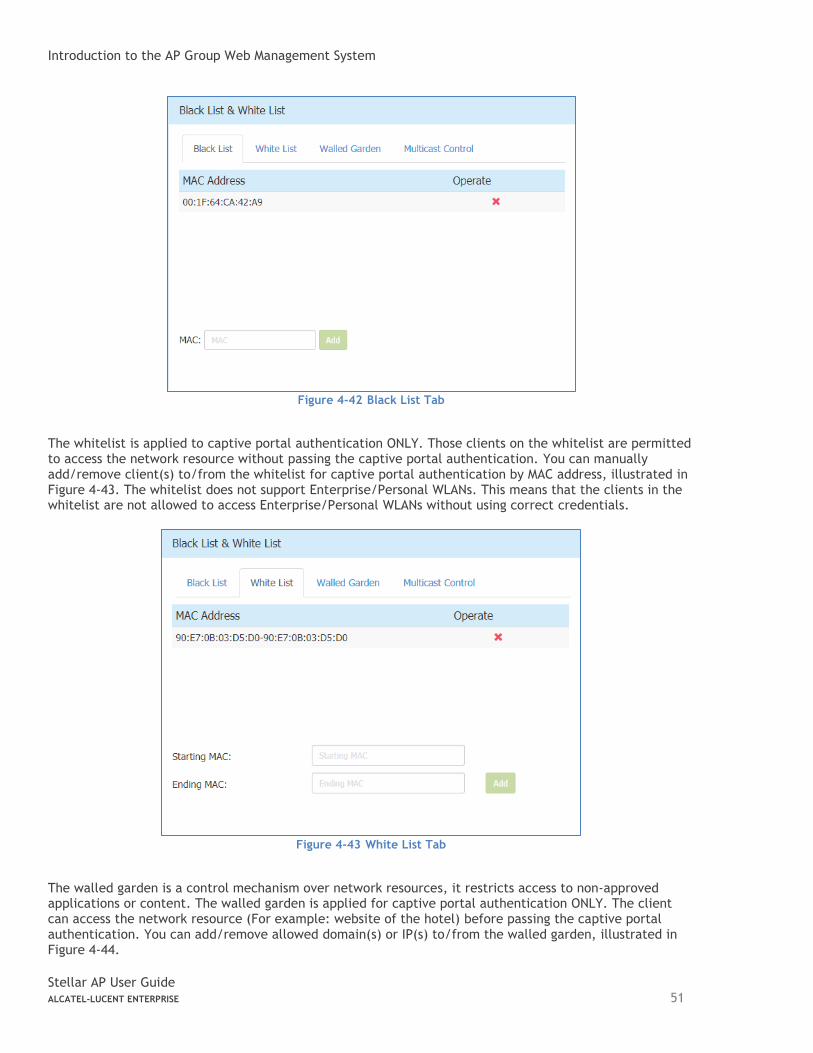
Introduction to the AP Group Web Management System
Stellar AP User Guide ALCATEL-LUCENT ENTERPRISE 51
Figure 4-42 Black List Tab
The whitelist is applied to captive portal authentication ONLY. Those clients on the whitelist are permitted to access the network resource without passing the captive portal authentication. You can manually add/remove client(s) to/from the whitelist for captive portal authentication by MAC address, illustrated in Figure 4-43. The whitelist does not support Enterprise/Personal WLANs. This means that the clients in the whitelist are not allowed to access Enterprise/Personal WLANs without using correct credentials.
Figure 4-43 White List Tab
The walled garden is a control mechanism over network resources, it restricts access to non-approved applications or content. The walled garden is applied for captive portal authentication ONLY. The client can access the network resource (For example: website of the hotel) before passing the captive portal authentication. You can add/remove allowed domain(s) or IP(s) to/from the walled garden, illustrated in Figure 4-44.
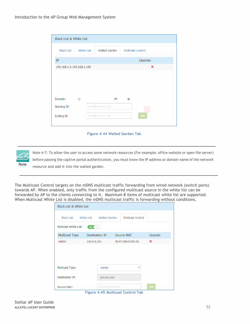
Introduction to the AP Group Web Management System
Stellar AP User Guide ALCATEL-LUCENT ENTERPRISE 52
Figure 4-44 Walled Garden Tab
Note 4-7: To allow the user to access some network resources (For example: office website or open file server)
before passing the captive portal authentication, you must know the IP address or domain name of the network
resource and add it into the walled garden.
The Multicast Control targets on the mDNS multicast traffic forwarding from wired network (switch ports) towards AP. When enabled, only traffic from the configured multicast source in the white list can be forwarded by AP to the clients connecting to it. Maximum 8 items of multicast white list are supported. When Multicast White List is disabled, the mDNS multicast traffic is forwarding without conditions.
Figure 4-45 Multicast Control Tab
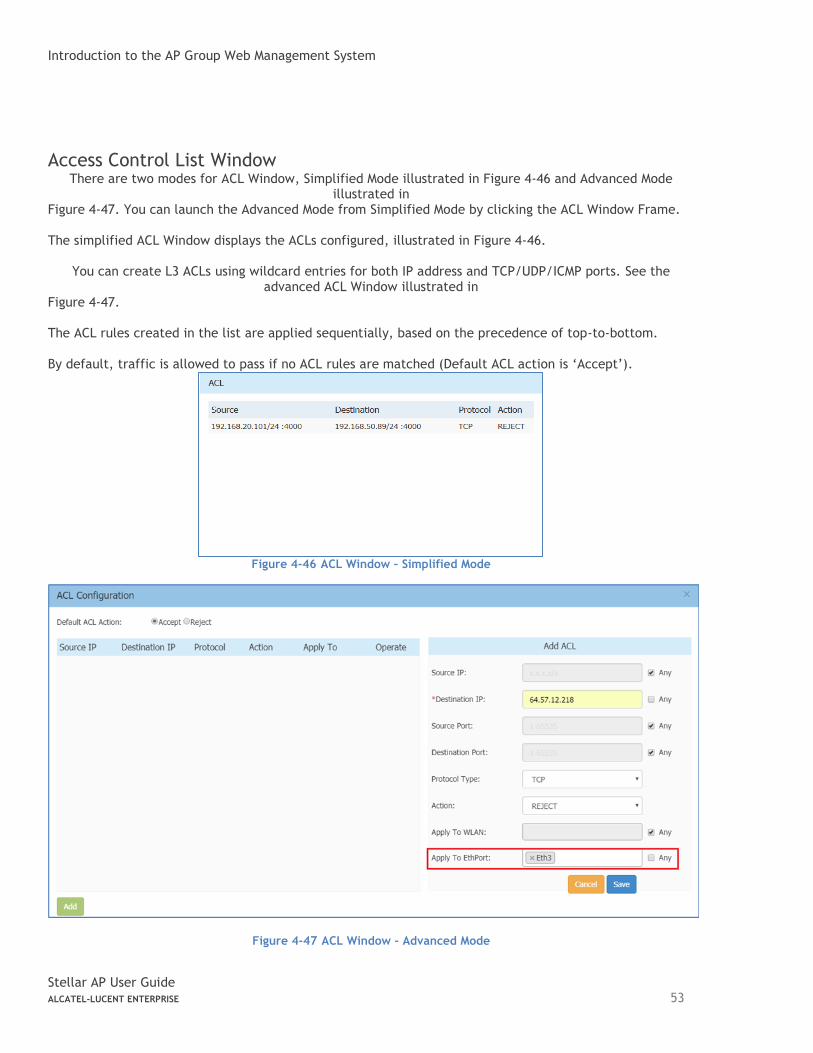
Introduction to the AP Group Web Management System
Stellar AP User Guide ALCATEL-LUCENT ENTERPRISE 53
Access Control List Window There are two modes for ACL Window, Simplified Mode illustrated in Figure 4-46 and Advanced Mode
illustrated in Figure 4-47. You can launch the Advanced Mode from Simplified Mode by clicking the ACL Window Frame. The simplified ACL Window displays the ACLs configured, illustrated in Figure 4-46.
You can create L3 ACLs using wildcard entries for both IP address and TCP/UDP/ICMP ports. See the advanced ACL Window illustrated in
Figure 4-47. The ACL rules created in the list are applied sequentially, based on the precedence of top-to-bottom. By default, traffic is allowed to pass if no ACL rules are matched (Default ACL action is ‘Accept’).
Figure 4-46 ACL Window – Simplified Mode
Figure 4-47 ACL Window – Advanced Mode
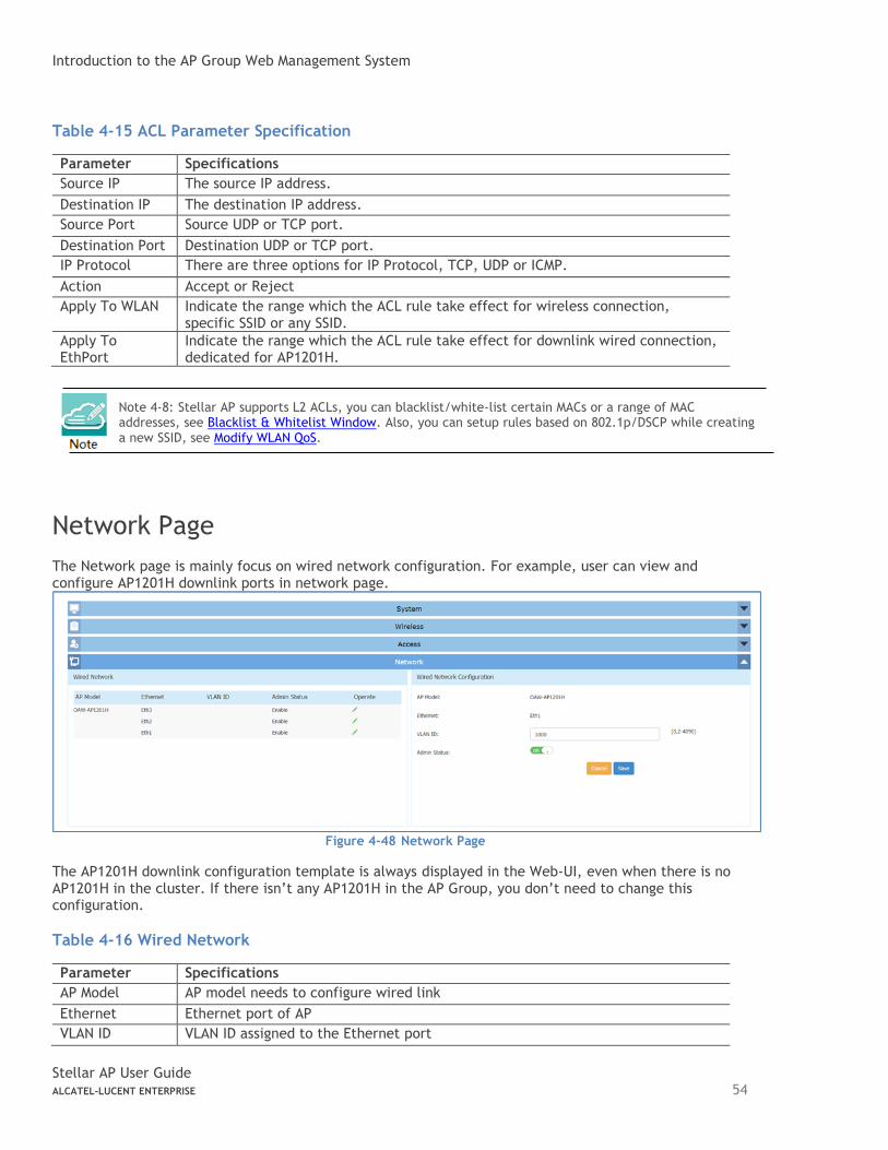
Introduction to the AP Group Web Management System
Stellar AP User Guide ALCATEL-LUCENT ENTERPRISE 54
Table 4-15 ACL Parameter Specification
Parameter Specifications
Source IP The source IP address.
Destination IP The destination IP address.
Source Port Source UDP or TCP port.
Destination Port Destination UDP or TCP port.
IP Protocol There are three options for IP Protocol, TCP, UDP or ICMP.
Action Accept or Reject
Apply To WLAN Indicate the range which the ACL rule take effect for wireless connection, specific SSID or any SSID.
Apply To EthPort
Indicate the range which the ACL rule take effect for downlink wired connection, dedicated for AP1201H.
Note 4-8: Stellar AP supports L2 ACLs, you can blacklist/white-list certain MACs or a range of MAC addresses, see Blacklist & Whitelist Window. Also, you can setup rules based on 802.1p/DSCP while creating a new SSID, see Modify WLAN QoS.
Network Page
The Network page is mainly focus on wired network configuration. For example, user can view and configure AP1201H downlink ports in network page.
Figure 4-48 Network Page
The AP1201H downlink configuration template is always displayed in the Web-UI, even when there is no AP1201H in the cluster. If there isn’t any AP1201H in the AP Group, you don’t need to change this configuration.
Table 4-16 Wired Network
Parameter Specifications
AP Model AP model needs to configure wired link
Ethernet Ethernet port of AP
VLAN ID VLAN ID assigned to the Ethernet port
Stellar AP User Guide ALCATEL-LUCENT ENTERPRISE 55
Admin Status Enable/Disable Ethernet port
5 WLAN Configuration
Configuring WLAN should be the first step when setting up your Wi-Fi network. This section contains the
following topics:
➔ Create NEW WLAN
➔ Delete Your WLAN
➔ Modify Your WLAN
➔ Modify WLAN Qos
Create New WLAN
To create a new WLAN, click on the hyperlink ‘New’ to launch the WLAN creation window. There are three security levels of WLANs that can be created: Enterprise, Personal and Open (Captive Portal).
Enterprise: Also referred to as 802.1X mode, this is designed for enterprise networks and requires a RADIUS authentication server. This requires a more complicated setup, but provides additional security (e.g. protection against dictionary attacks on short passwords). Various kinds of the Extensible Authentication Protocol (EAP) are used for authentication. Enterprise mode is available with both WPA and WPA2.
Personal: Also referred to as PSK (pre-shared key) mode, this is designed for home and small office networks and doesn't require an authentication server. Each wireless network device encrypts the network traffic using a 256 bit key. This key may be entered either as a string of 64 hexadecimal digits, or as a passphrase of 8 to 63 printable ASCII characters. Personal mode is available with both WPA and WPA2.
Open (Captive Portal): No Authentication or encryption method for the wireless network. User data will be transmitted as plain text transmit mode over the air. Captive portals are mainly used in wireless open networks where the users are shown a welcome message informing them of the conditions of access. Often captive portals are used for marketing and commercial communication purposes and they allow the providers of this service to display or send advertisements to users who connect to the Wi-Fi access points.
Create an Enterprise WLAN Enterprise WLAN creation window has two display modes, simplified mode and advanced mode, respectively illustrated in Figure 5-1and Figure 5-2. You can switch to advanced mode from simplified mode
by clicking the hyperlink . There are six essential parameters needed to be configured in simplified mode, they are WLAN Name, Security Level, Key Management and AuthServer, AuthPort and AuthSecret. Other parameters will be considered as per the default value. To configure other advanced parameters, you must switch to advanced mode. Refer to Table 5-1 for details about each parameter.
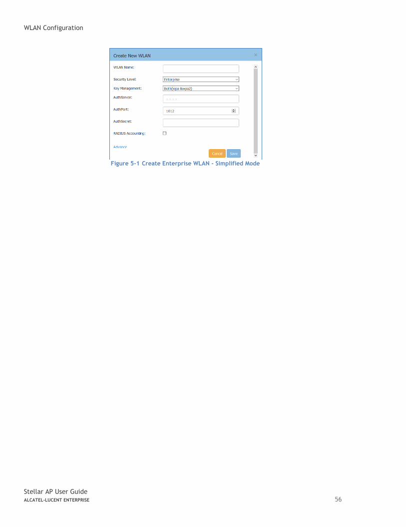
WLAN Configuration
Stellar AP User Guide ALCATEL-LUCENT ENTERPRISE 56
Figure 5-1 Create Enterprise WLAN - Simplified Mode
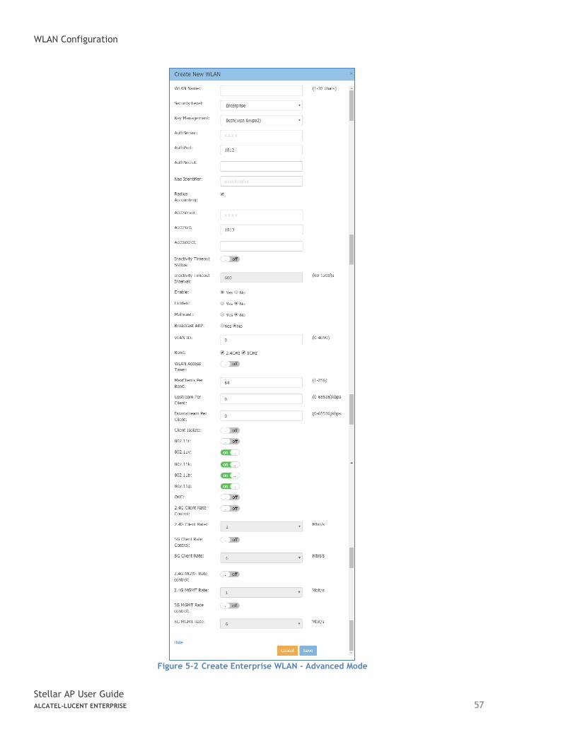
WLAN Configuration
Stellar AP User Guide ALCATEL-LUCENT ENTERPRISE 57
Figure 5-2 Create Enterprise WLAN - Advanced Mode
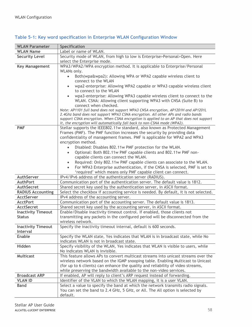
WLAN Configuration
Stellar AP User Guide ALCATEL-LUCENT ENTERPRISE 58
Table 5-1: Key word specification in Enterprise WLAN Configuration Window
WLAN Parameter Specification
WLAN Name Label or name of WLAN.
Security Level Security mode of WLAN, from high to low is Enterprise>Personal>Open. Here select the Enterprise mode.
Key Management WPA3/WPA2/WPA encryption method. It is applicable to Enterprise/Personal WLANs only.
• Both(wpa&wpa2): Allowing WPA or WPA2 capable wireless client to connect to the WLAN
• wpa2-enterprise: Allowing WPA2 capable or WPA3 capable wireless client to connect to the WLAN
• wpa3-enterprise: Allowing WPA3 capable wireless client to connect to the WLAN. CSNA: Allowing client supporting WPA3 with CNSA (Suite B) to connect when checked.
Note: AP1101 full band does not support WPA3 CNSA encryption, AP1201H and AP1201L 2.4Ghz band does not support WPA3 CSNA encryption. All other APs and radio bands support CSNA encryption. When CSNA encryption is applied to an AP that does not support it, the encryption will automatically fall back to non-CSNA mode (WPA2).
PMF Stellar supports the IEEE802.11w standard, also known as Protected Management Frames (PMF). The PMF function increases the security by providing data confidentiality of management frames. PMF is applicable for WPA2 and WPA3 encryption method.
• Disabled: Disables 802.11w PMF protection for the WLAN.
• Optional: Both 802.11w PMF capable clients and 802.11w PMF non-capable clients can connect the WLAN.
• Required: Only 802.11w PMF capable clients can associate to the WLAN.
• For WPA3 Enterprise authentication, if the CNSA is selected, PMF is set to ‘required’ which means only PMF capable client can connect.
AuthServer IPv4/IPv6 address of the authentication server (RADIUS).
AuthPort Communication port of the authentication server. The default value is 1812.
AuthSecret Shared secret key used by the authentication server, in ASCII format.
RADIUS Accounting Select the checkbox if accounting service is needed. By default, it is not selected.
AcctServer IPv4 address of the accounting server.
AcctPort Communication port of the accounting server. The default value is 1813.
AcctSecret Shared secret key used by the accounting server, in ASCII format.
Inactivity Timeout Status
Enable/Disable inactivity timeout control. If enabled, those clients not transmitting any packets in the configured period will be disconnected from the wireless network.
Inactivity Timeout Interval
Specify the inactivity timeout internal, default is 600 seconds.
Enable Specify the WLAN state, Yes indicates that WLAN is in broadcast state, while No indicates WLAN is not in broadcast state.
Hidden Specify visibility of the WLAN, Yes indicates that WLAN is visible to users, while No indicates WLAN is invisible.
Multicast This feature allows APs to convert multicast streams into unicast streams over the wireless network based on the IGMP snooping table. Enabling Multicast to Unicast (for up to 6 clients) can enhance the quality and reliability of video streams, while preserving the bandwidth available to the non-video services.
Broadcast ARP If enabled, AP will reply to client’s ARP request instead of forwarding.
VLAN ID Identifier of the VLAN to which the WLAN mapping, it is a user VLAN.
Band Select a value to specify the band at which the network transmits radio signals. You can set the band to 2.4 GHz, 5 GHz, or All. The All option is selected by default.

WLAN Configuration
Stellar AP User Guide ALCATEL-LUCENT ENTERPRISE 59
Scope Type Specify the scope of APs in the cluster which will create the WLAN.
• All – All APs in the cluster will create the WLAN.
• Group – Select the APs which will create the WLAN. The AP which MAC address is in the group will be valid for the WLAN.
WLAN Access Timer Specify the WLAN working period, in which only SSID broadcasts. If NOT configured (Disabled), SSID will always broadcast if the WLAN is activated.
• Access Days – Specify the days for broadcasting SSID per week.
• Operational Hours – Specify the time of the day in which broadcasting SSID.
Max Clients per band
Specify the maximum number of clients that can be configured for each BSSID on a WLAN. You can specify a value within the range of 1 to 256. The default value is 64.
Upstream Per Client
Specify the maximum upstream bandwidth limitation for each user.
Downstream Per Client
Specify the maximum downstream bandwidth limitation for each user.
Client Isolate Not permit the clients attached to the same WLAN to communicate with each other, they can only communicate with upstream gateway.
802.11r Select to enable IEEE 802.11r (Fast BSS Transition). The Fast BSS Transition mechanism minimizes the delay when a client transitions from one BSS to another within the same group.
802.11v Enables/Disables 802.11v. 802.11v standard defines mechanisms for wireless network management enhancements and BSS transition management. It allows client devices to exchange information about the network topology and RF environment. The BSS transition management mechanism enables an AP to request a voice client to transition to a specific AP, or suggest a set of preferred APs to a client, due to network load balancing or BSS termination. It also helps the client identify the best AP to transition to as they roam.
802.11k Enables/Disables 802.11k. The 802.11k protocol enables APs and clients to dynamically measure the available radio resources. When 802.11k is enabled, APs and clients send neighbor reports, beacon reports, and link measurement reports to each other.
802.11b Enables/Disables allowing 11b legacy clients connect to AP
802.11g Enables/Disables allowing 11g legacy clients connect to AP
2.4G Client Rate Control
Enables/Disables 2.4G band access control based on client data rate
2.4G Client Rate 2.4G band client with lower data speed will not be allowed to access, recommended value 12
5G Client Rate Control
Enables/Disables 5G band access control based on client data rate
5G Client Rate 5G band client with lower data speed will not be allowed to access, recommended value 24
2.4G MGMT Rate Control
Enables/Disables 2.4G band wireless management frame rate control
2.4G MGMT Rate 2.4G band wireless management frame transmit rate, higher value means less coverage, lower value means larger coverage. 2.4G Beacon frame does not support 9 Mbps or 18 Mbps speed. When 9/18 Mbps is configured for 2.4G MGMT Rate, beacon frame will broadcast on 11/24 Mbps rate and other management frames (such as probe frame) will broadcast on 9/18 Mbps.
5G MGMT Rate Control
Enables/Disables 5G band wireless management frame rate control
5G MGMT Rate 5G band wireless management frame transmit rate, higher value means less coverage, lower value means larger coverage. 5G Beacon frame does not support 9 Mbps speed. When 9 Mbps is configured for 5G MGMT Rate, beacon frame will
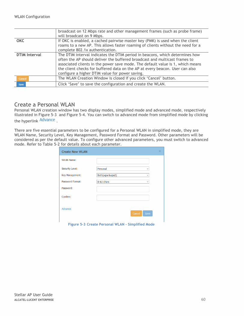
WLAN Configuration
Stellar AP User Guide ALCATEL-LUCENT ENTERPRISE 60
broadcast on 12 Mbps rate and other management frames (such as probe frame) will broadcast on 9 Mbps.
OKC If OKC is enabled, a cached pairwise master key (PMK) is used when the client roams to a new AP. This allows faster roaming of clients without the need for a complete 802.1x authentication.
DTIM Interval The DTIM interval indicates the DTIM period in beacons, which determines how often the AP should deliver the buffered broadcast and multicast frames to associated clients in the power save mode. The default value is 1, which means the client checks for buffered data on the AP at every beacon. User can also configure a higher DTIM value for power saving.
The WLAN Creation Window is closed if you click ‘Cancel’ button.
Click ‘Save’ to save the configuration and create the WLAN.
Create a Personal WLAN Personal WLAN creation window has two display modes, simplified mode and advanced mode, respectively illustrated in Figure 5-3 and Figure 5-4. You can switch to advanced mode from simplified mode by clicking
the hyperlink . There are five essential parameters to be configured for a Personal WLAN in simplified mode, they are WLAN Name, Security Level, Key Management, Password Format and Password. Other parameters will be considered as per the default value. To configure other advanced parameters, you must switch to advanced mode. Refer to Table 5-2 for details about each parameter.
Figure 5-3 Create Personal WLAN - Simplified Mode
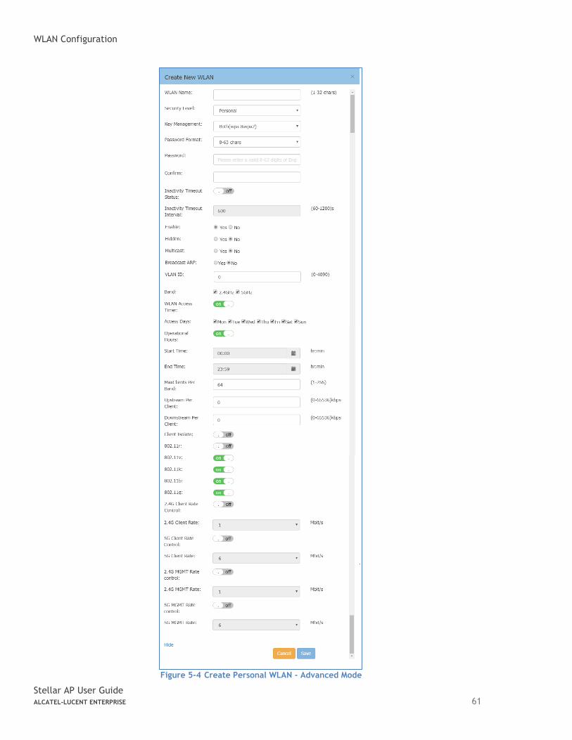
WLAN Configuration
Stellar AP User Guide ALCATEL-LUCENT ENTERPRISE 61
Figure 5-4 Create Personal WLAN - Advanced Mode
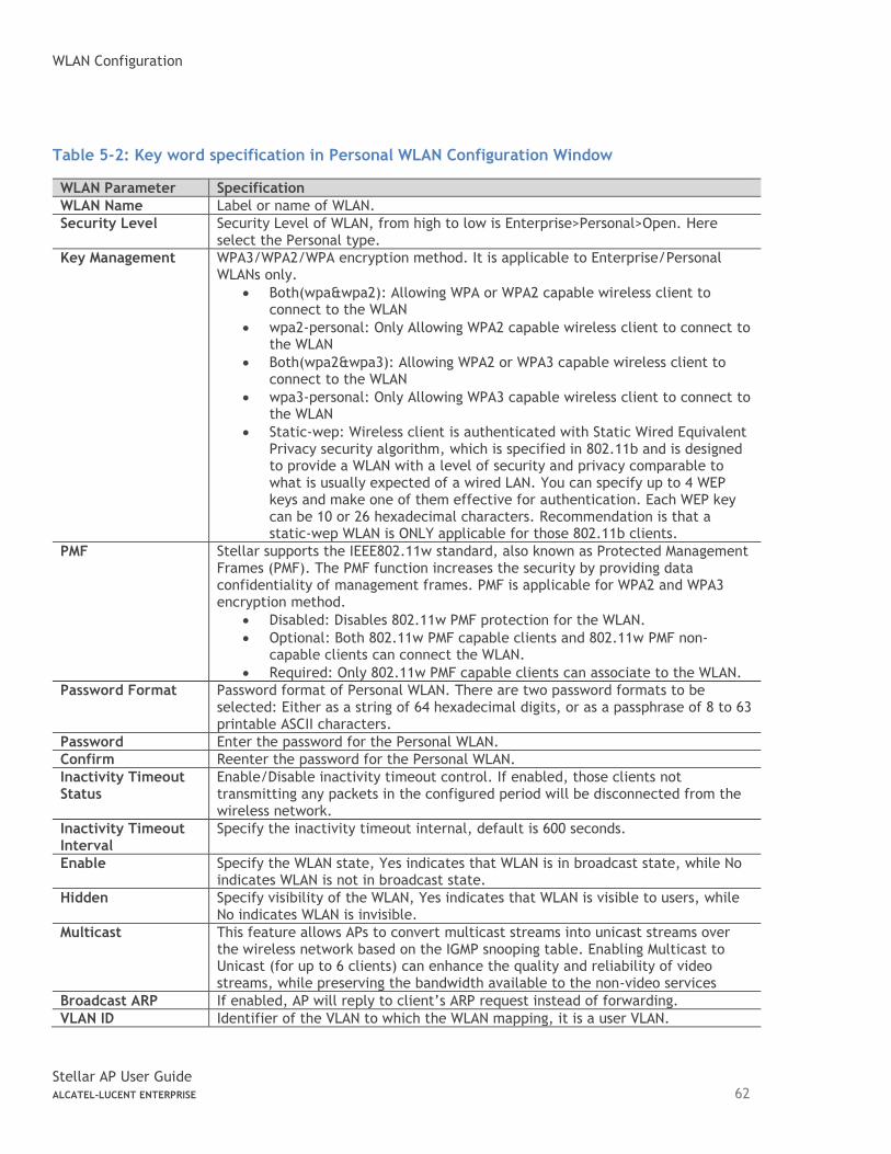
WLAN Configuration
Stellar AP User Guide ALCATEL-LUCENT ENTERPRISE 62
Table 5-2: Key word specification in Personal WLAN Configuration Window
WLAN Parameter Specification
WLAN Name Label or name of WLAN.
Security Level Security Level of WLAN, from high to low is Enterprise>Personal>Open. Here select the Personal type.
Key Management WPA3/WPA2/WPA encryption method. It is applicable to Enterprise/Personal WLANs only.
• Both(wpa&wpa2): Allowing WPA or WPA2 capable wireless client to connect to the WLAN
• wpa2-personal: Only Allowing WPA2 capable wireless client to connect to the WLAN
• Both(wpa2&wpa3): Allowing WPA2 or WPA3 capable wireless client to connect to the WLAN
• wpa3-personal: Only Allowing WPA3 capable wireless client to connect to the WLAN
• Static-wep: Wireless client is authenticated with Static Wired Equivalent Privacy security algorithm, which is specified in 802.11b and is designed to provide a WLAN with a level of security and privacy comparable to what is usually expected of a wired LAN. You can specify up to 4 WEP keys and make one of them effective for authentication. Each WEP key can be 10 or 26 hexadecimal characters. Recommendation is that a static-wep WLAN is ONLY applicable for those 802.11b clients.
PMF Stellar supports the IEEE802.11w standard, also known as Protected Management Frames (PMF). The PMF function increases the security by providing data confidentiality of management frames. PMF is applicable for WPA2 and WPA3 encryption method.
• Disabled: Disables 802.11w PMF protection for the WLAN.
• Optional: Both 802.11w PMF capable clients and 802.11w PMF non-capable clients can connect the WLAN.
• Required: Only 802.11w PMF capable clients can associate to the WLAN.
Password Format Password format of Personal WLAN. There are two password formats to be selected: Either as a string of 64 hexadecimal digits, or as a passphrase of 8 to 63 printable ASCII characters.
Password Enter the password for the Personal WLAN.
Confirm Reenter the password for the Personal WLAN.
Inactivity Timeout Status
Enable/Disable inactivity timeout control. If enabled, those clients not transmitting any packets in the configured period will be disconnected from the wireless network.
Inactivity Timeout Interval
Specify the inactivity timeout internal, default is 600 seconds.
Enable Specify the WLAN state, Yes indicates that WLAN is in broadcast state, while No indicates WLAN is not in broadcast state.
Hidden Specify visibility of the WLAN, Yes indicates that WLAN is visible to users, while No indicates WLAN is invisible.
Multicast This feature allows APs to convert multicast streams into unicast streams over the wireless network based on the IGMP snooping table. Enabling Multicast to Unicast (for up to 6 clients) can enhance the quality and reliability of video streams, while preserving the bandwidth available to the non-video services
Broadcast ARP If enabled, AP will reply to client’s ARP request instead of forwarding.
VLAN ID Identifier of the VLAN to which the WLAN mapping, it is a user VLAN.

WLAN Configuration
Stellar AP User Guide ALCATEL-LUCENT ENTERPRISE 63
Band Select a value to specify the band at which the network transmits radio signals. You can set the band to 2.4 GHz, 5 GHz, or All. The All option is selected by default.
Scope Type Specify the scope of APs in the cluster which will create the WLAN.
• All – All APs in the cluster will create the WLAN. Group – Select the APs which will create the WLAN. The AP which MAC address is in the group will be valid for the WLAN.
WLAN Access Timer Specify the WLAN working period, in which only SSID broadcasts. If NOT configured (Disabled), SSID will always broadcast if the WLAN is activated.
• Access Days – Specify the days for broadcasting SSID per week.
• Operational Hours – Specify the time of the day in which broadcasting SSID.
Max Clients per band
Specify the maximum number of clients that can be configured for each BSSID on a WLAN. You can specify a value within the range of 1 to 256. The default value is 64.
Upstream Per Client Specify the maximum upstream bandwidth limitation for each user.
Downstream Per Client
Specify the maximum downstream bandwidth limitation for each user.
Client Isolate Not permit the clients attached to the same WLAN to communicate with each other, they can only communicate with upstream gateway.
802.11r Select to enable IEEE 802.11r (Fast BSS Transition). The Fast BSS Transition mechanism minimizes the delay when a client transitions from one BSS to another within the same group.
802.11v Enables/Disables 802.11v. 802.11v standard defines mechanisms for wireless network management enhancements and BSS transition management. It allows client devices to exchange information about the network topology and RF environment. The BSS transition management mechanism enables an AP to request a voice client to transition to a specific AP, or suggest a set of preferred APs to a client, due to network load balancing or BSS termination. It also helps the client identify the best AP to transition to as they roam.
802.11k Enables/Disables 802.11k. The 802.11k protocol enables APs and clients to dynamically measure the available radio resources. When 802.11k is enabled, APs and clients send neighbor reports, beacon reports, and link measurement reports to each other.
802.11b Enables/Disables allowing 11b legacy clients connect to AP
802.11g Enables/Disables allowing 11g legacy clients connect to AP
2.4G Client Rate Control
Enables/Disables 2.4G band accessing control based on client data rate
2.4G Client Rate 2.4G band client with lower data speed will not be allowed to access, recommended value 12
5G Client Rate Control
Enables/Disables 5G band accessing control based on client data rate
5G Client Rate 5G band client with lower data speed will not be allowed to access, recommended value 24
2.4G MGMT Rate Control
Enables/Disables 2.4G band wireless management frame rate control
2.4G MGMT Rate 2.4G band wireless management frame transmit rate, higher value means less coverage, lower value means larger coverage
5G MGMT Rate Control
Enables/Disables 5G band wireless management frame rate control
5G MGMT Rate 5G band wireless management frame transmit rate, higher value means less coverage, lower value means larger coverage
DTIM Interval The DTIM interval indicates the DTIM period in beacons, which determines how often the AP should deliver the buffered broadcast and multicast frames to associated clients in the power save mode. The default value is 1, which means
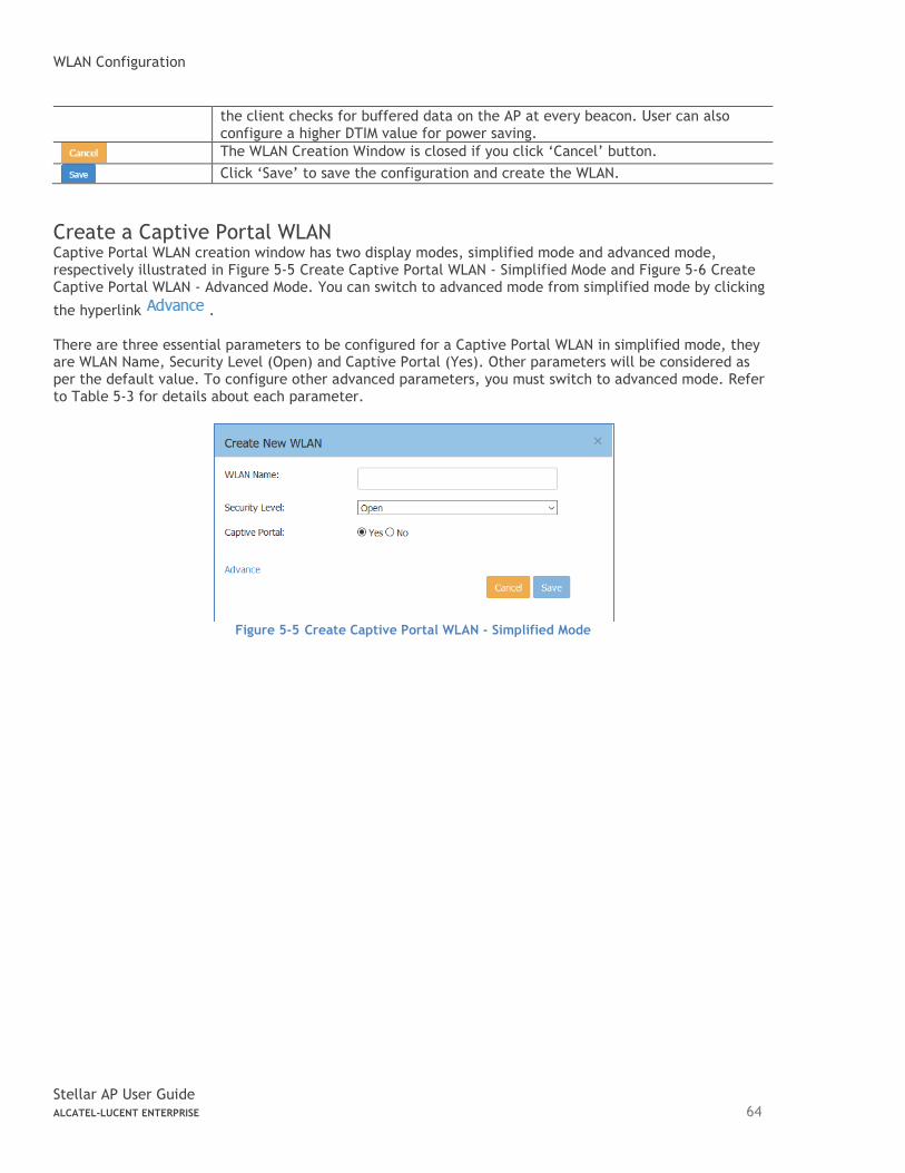
WLAN Configuration
Stellar AP User Guide ALCATEL-LUCENT ENTERPRISE 64
the client checks for buffered data on the AP at every beacon. User can also configure a higher DTIM value for power saving.
The WLAN Creation Window is closed if you click ‘Cancel’ button.
Click ‘Save’ to save the configuration and create the WLAN.
Create a Captive Portal WLAN Captive Portal WLAN creation window has two display modes, simplified mode and advanced mode, respectively illustrated in Figure 5-5 Create Captive Portal WLAN - Simplified Mode and Figure 5-6 Create Captive Portal WLAN - Advanced Mode. You can switch to advanced mode from simplified mode by clicking
the hyperlink . There are three essential parameters to be configured for a Captive Portal WLAN in simplified mode, they are WLAN Name, Security Level (Open) and Captive Portal (Yes). Other parameters will be considered as per the default value. To configure other advanced parameters, you must switch to advanced mode. Refer to Table 5-3 for details about each parameter.
Figure 5-5 Create Captive Portal WLAN - Simplified Mode
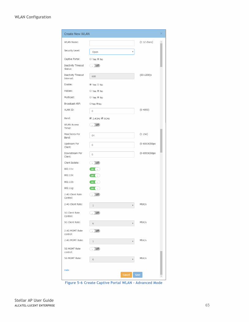
WLAN Configuration
Stellar AP User Guide ALCATEL-LUCENT ENTERPRISE 65
Figure 5-6 Create Captive Portal WLAN - Advanced Mode
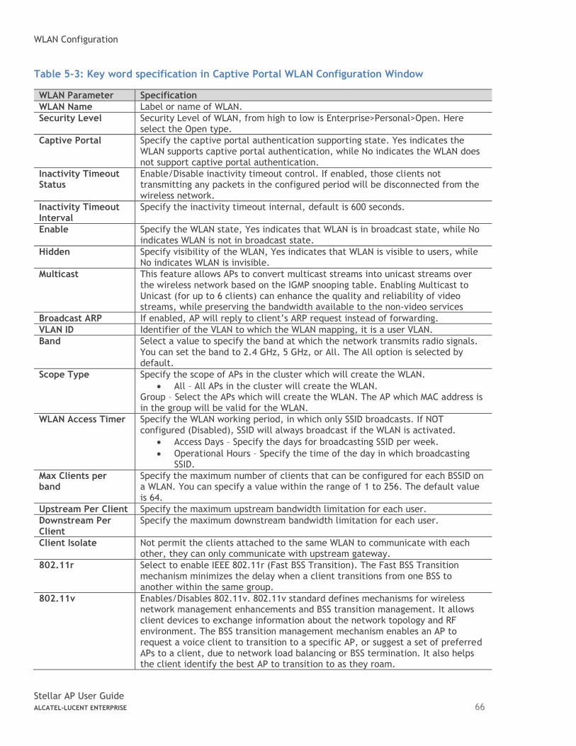
WLAN Configuration
Stellar AP User Guide ALCATEL-LUCENT ENTERPRISE 66
Table 5-3: Key word specification in Captive Portal WLAN Configuration Window
WLAN Parameter Specification
WLAN Name Label or name of WLAN.
Security Level Security Level of WLAN, from high to low is Enterprise>Personal>Open. Here select the Open type.
Captive Portal Specify the captive portal authentication supporting state. Yes indicates the WLAN supports captive portal authentication, while No indicates the WLAN does not support captive portal authentication.
Inactivity Timeout Status
Enable/Disable inactivity timeout control. If enabled, those clients not transmitting any packets in the configured period will be disconnected from the wireless network.
Inactivity Timeout Interval
Specify the inactivity timeout internal, default is 600 seconds.
Enable Specify the WLAN state, Yes indicates that WLAN is in broadcast state, while No indicates WLAN is not in broadcast state.
Hidden Specify visibility of the WLAN, Yes indicates that WLAN is visible to users, while No indicates WLAN is invisible.
Multicast This feature allows APs to convert multicast streams into unicast streams over the wireless network based on the IGMP snooping table. Enabling Multicast to Unicast (for up to 6 clients) can enhance the quality and reliability of video streams, while preserving the bandwidth available to the non-video services
Broadcast ARP If enabled, AP will reply to client’s ARP request instead of forwarding.
VLAN ID Identifier of the VLAN to which the WLAN mapping, it is a user VLAN.
Band Select a value to specify the band at which the network transmits radio signals. You can set the band to 2.4 GHz, 5 GHz, or All. The All option is selected by default.
Scope Type Specify the scope of APs in the cluster which will create the WLAN.
• All – All APs in the cluster will create the WLAN. Group – Select the APs which will create the WLAN. The AP which MAC address is in the group will be valid for the WLAN.
WLAN Access Timer Specify the WLAN working period, in which only SSID broadcasts. If NOT configured (Disabled), SSID will always broadcast if the WLAN is activated.
• Access Days – Specify the days for broadcasting SSID per week.
• Operational Hours – Specify the time of the day in which broadcasting SSID.
Max Clients per band
Specify the maximum number of clients that can be configured for each BSSID on a WLAN. You can specify a value within the range of 1 to 256. The default value is 64.
Upstream Per Client Specify the maximum upstream bandwidth limitation for each user.
Downstream Per Client
Specify the maximum downstream bandwidth limitation for each user.
Client Isolate Not permit the clients attached to the same WLAN to communicate with each other, they can only communicate with upstream gateway.
802.11r Select to enable IEEE 802.11r (Fast BSS Transition). The Fast BSS Transition mechanism minimizes the delay when a client transitions from one BSS to another within the same group.
802.11v Enables/Disables 802.11v. 802.11v standard defines mechanisms for wireless network management enhancements and BSS transition management. It allows client devices to exchange information about the network topology and RF environment. The BSS transition management mechanism enables an AP to request a voice client to transition to a specific AP, or suggest a set of preferred APs to a client, due to network load balancing or BSS termination. It also helps the client identify the best AP to transition to as they roam.
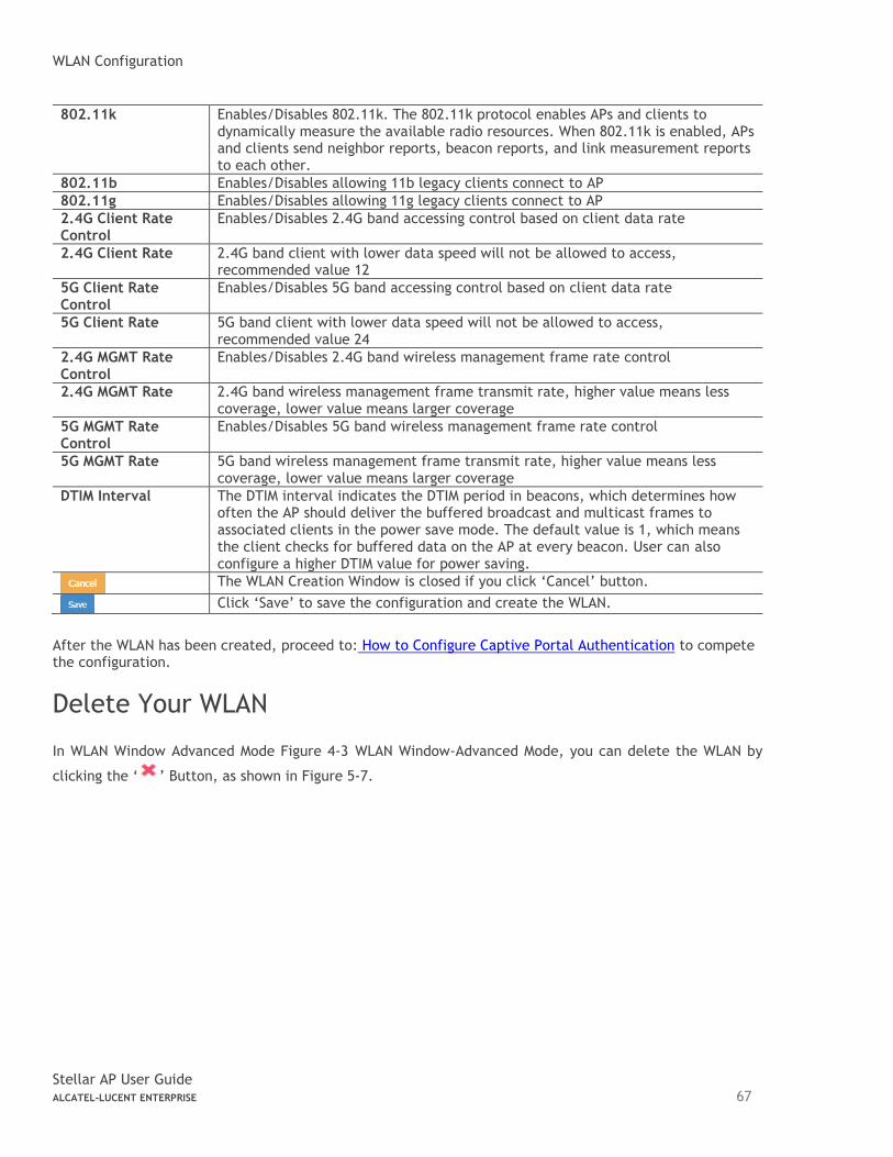
WLAN Configuration
Stellar AP User Guide ALCATEL-LUCENT ENTERPRISE 67
802.11k Enables/Disables 802.11k. The 802.11k protocol enables APs and clients to dynamically measure the available radio resources. When 802.11k is enabled, APs and clients send neighbor reports, beacon reports, and link measurement reports to each other.
802.11b Enables/Disables allowing 11b legacy clients connect to AP
802.11g Enables/Disables allowing 11g legacy clients connect to AP
2.4G Client Rate Control
Enables/Disables 2.4G band accessing control based on client data rate
2.4G Client Rate 2.4G band client with lower data speed will not be allowed to access, recommended value 12
5G Client Rate Control
Enables/Disables 5G band accessing control based on client data rate
5G Client Rate 5G band client with lower data speed will not be allowed to access, recommended value 24
2.4G MGMT Rate Control
Enables/Disables 2.4G band wireless management frame rate control
2.4G MGMT Rate 2.4G band wireless management frame transmit rate, higher value means less coverage, lower value means larger coverage
5G MGMT Rate Control
Enables/Disables 5G band wireless management frame rate control
5G MGMT Rate 5G band wireless management frame transmit rate, higher value means less coverage, lower value means larger coverage
DTIM Interval The DTIM interval indicates the DTIM period in beacons, which determines how often the AP should deliver the buffered broadcast and multicast frames to associated clients in the power save mode. The default value is 1, which means the client checks for buffered data on the AP at every beacon. User can also configure a higher DTIM value for power saving.
The WLAN Creation Window is closed if you click ‘Cancel’ button.
Click ‘Save’ to save the configuration and create the WLAN.
After the WLAN has been created, proceed to: How to Configure Captive Portal Authentication to compete the configuration.
Delete Your WLAN
In WLAN Window Advanced Mode Figure 4-3 WLAN Window-Advanced Mode, you can delete the WLAN by
clicking the ‘ ’ Button, as shown in Figure 5-7.
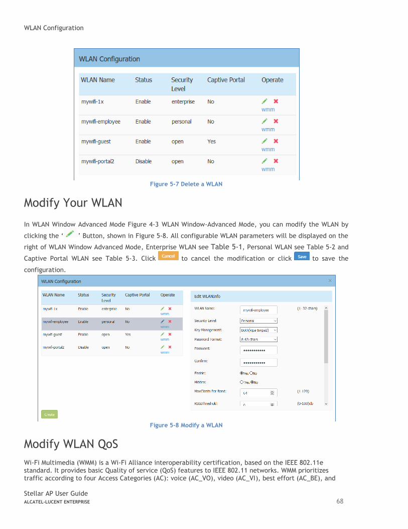
WLAN Configuration
Stellar AP User Guide ALCATEL-LUCENT ENTERPRISE 68
Figure 5-7 Delete a WLAN
Modify Your WLAN
In WLAN Window Advanced Mode Figure 4-3 WLAN Window-Advanced Mode, you can modify the WLAN by
clicking the ‘ ’ Button, shown in Figure 5-8. All configurable WLAN parameters will be displayed on the
right of WLAN Window Advanced Mode, Enterprise WLAN see Table 5-1, Personal WLAN see Table 5-2 and
Captive Portal WLAN see Table 5-3. Click to cancel the modification or click to save the
configuration.
Figure 5-8 Modify a WLAN
Modify WLAN QoS
Wi-Fi Multimedia (WMM) is a Wi-Fi Alliance interoperability certification, based on the IEEE 802.11e standard. It provides basic Quality of service (QoS) features to IEEE 802.11 networks. WMM prioritizes traffic according to four Access Categories (AC): voice (AC_VO), video (AC_VI), best effort (AC_BE), and
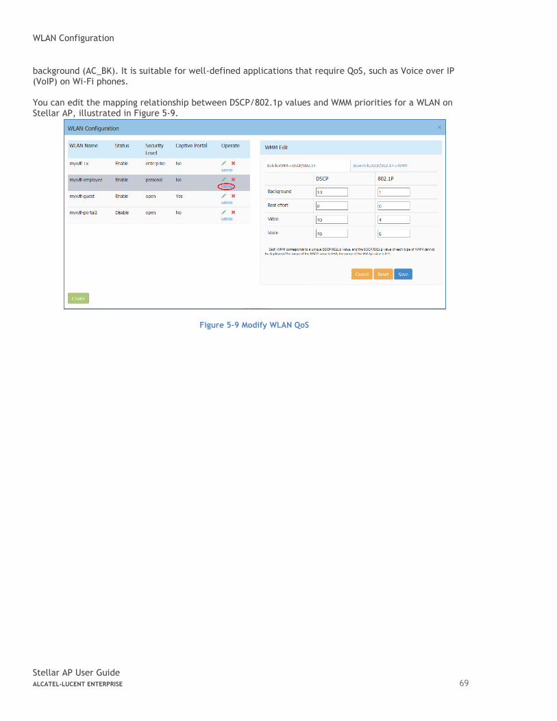
WLAN Configuration
Stellar AP User Guide ALCATEL-LUCENT ENTERPRISE 69
background (AC_BK). It is suitable for well-defined applications that require QoS, such as Voice over IP (VoIP) on Wi-Fi phones. You can edit the mapping relationship between DSCP/802.1p values and WMM priorities for a WLAN on Stellar AP, illustrated in Figure 5-9.
Figure 5-9 Modify WLAN QoS
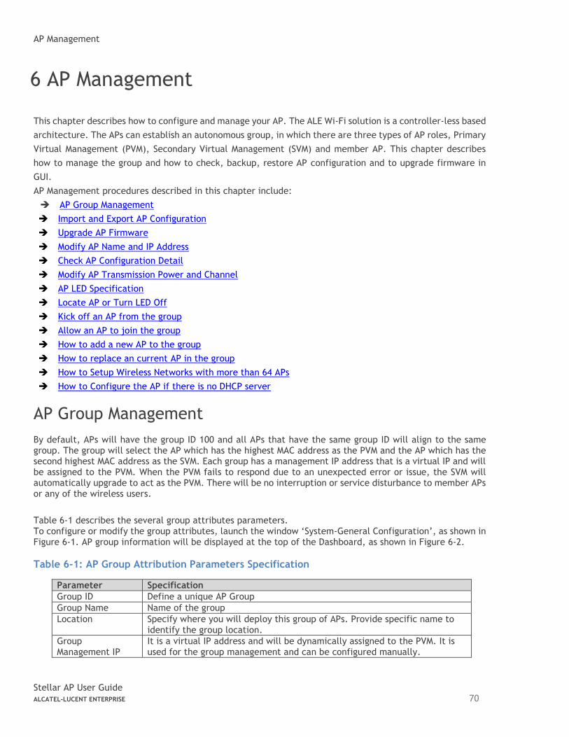
AP Management
Stellar AP User Guide ALCATEL-LUCENT ENTERPRISE 70
6 AP Management
This chapter describes how to configure and manage your AP. The ALE Wi-Fi solution is a controller-less based
architecture. The APs can establish an autonomous group, in which there are three types of AP roles, Primary
Virtual Management (PVM), Secondary Virtual Management (SVM) and member AP. This chapter describes
how to manage the group and how to check, backup, restore AP configuration and to upgrade firmware in
GUI.
AP Management procedures described in this chapter include:
➔ AP Group Management
➔ Import and Export AP Configuration
➔ Upgrade AP Firmware
➔ Modify AP Name and IP Address
➔ Check AP Configuration Detail
➔ Modify AP Transmission Power and Channel
➔ AP LED Specification
➔ Locate AP or Turn LED Off
➔ Kick off an AP from the group
➔ Allow an AP to join the group
➔ How to add a new AP to the group
➔ How to replace an current AP in the group
➔ How to Setup Wireless Networks with more than 64 APs
➔ How to Configure the AP if there is no DHCP server
AP Group Management
By default, APs will have the group ID 100 and all APs that have the same group ID will align to the same group. The group will select the AP which has the highest MAC address as the PVM and the AP which has the second highest MAC address as the SVM. Each group has a management IP address that is a virtual IP and will be assigned to the PVM. When the PVM fails to respond due to an unexpected error or issue, the SVM will automatically upgrade to act as the PVM. There will be no interruption or service disturbance to member APs or any of the wireless users.
Table 6-1 describes the several group attributes parameters. To configure or modify the group attributes, launch the window ‘System-General Configuration’, as shown in Figure 6-1. AP group information will be displayed at the top of the Dashboard, as shown in Figure 6-2.
Table 6-1: AP Group Attribution Parameters Specification
Parameter Specification
Group ID Define a unique AP Group
Group Name Name of the group
Location Specify where you will deploy this group of APs. Provide specific name to identify the group location.
Group Management IP
It is a virtual IP address and will be dynamically assigned to the PVM. It is used for the group management and can be configured manually.
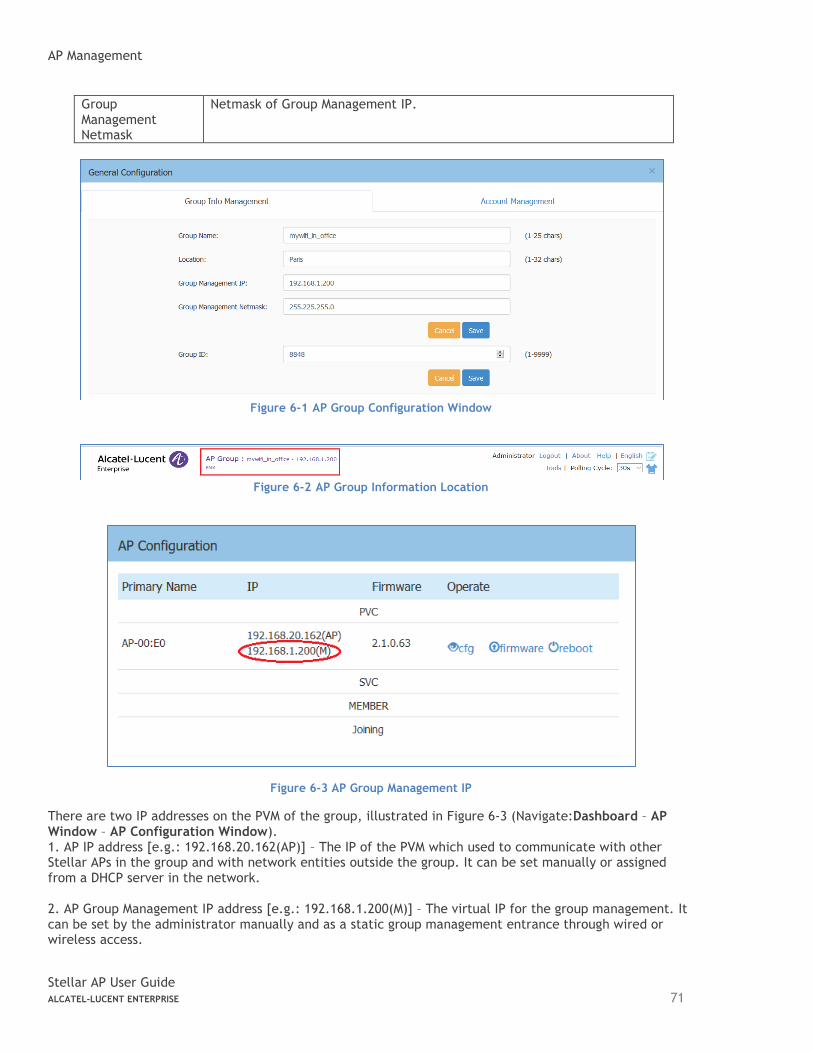
AP Management
Stellar AP User Guide ALCATEL-LUCENT ENTERPRISE 71
Group Management Netmask
Netmask of Group Management IP.
Figure 6-1 AP Group Configuration Window
Figure 6-2 AP Group Information Location
Figure 6-3 AP Group Management IP
There are two IP addresses on the PVM of the group, illustrated in Figure 6-3 (Navigate:Dashboard – AP Window – AP Configuration Window). 1. AP IP address [e.g.: 192.168.20.162(AP)] – The IP of the PVM which used to communicate with other Stellar APs in the group and with network entities outside the group. It can be set manually or assigned from a DHCP server in the network. 2. AP Group Management IP address [e.g.: 192.168.1.200(M)] – The virtual IP for the group management. It can be set by the administrator manually and as a static group management entrance through wired or wireless access.
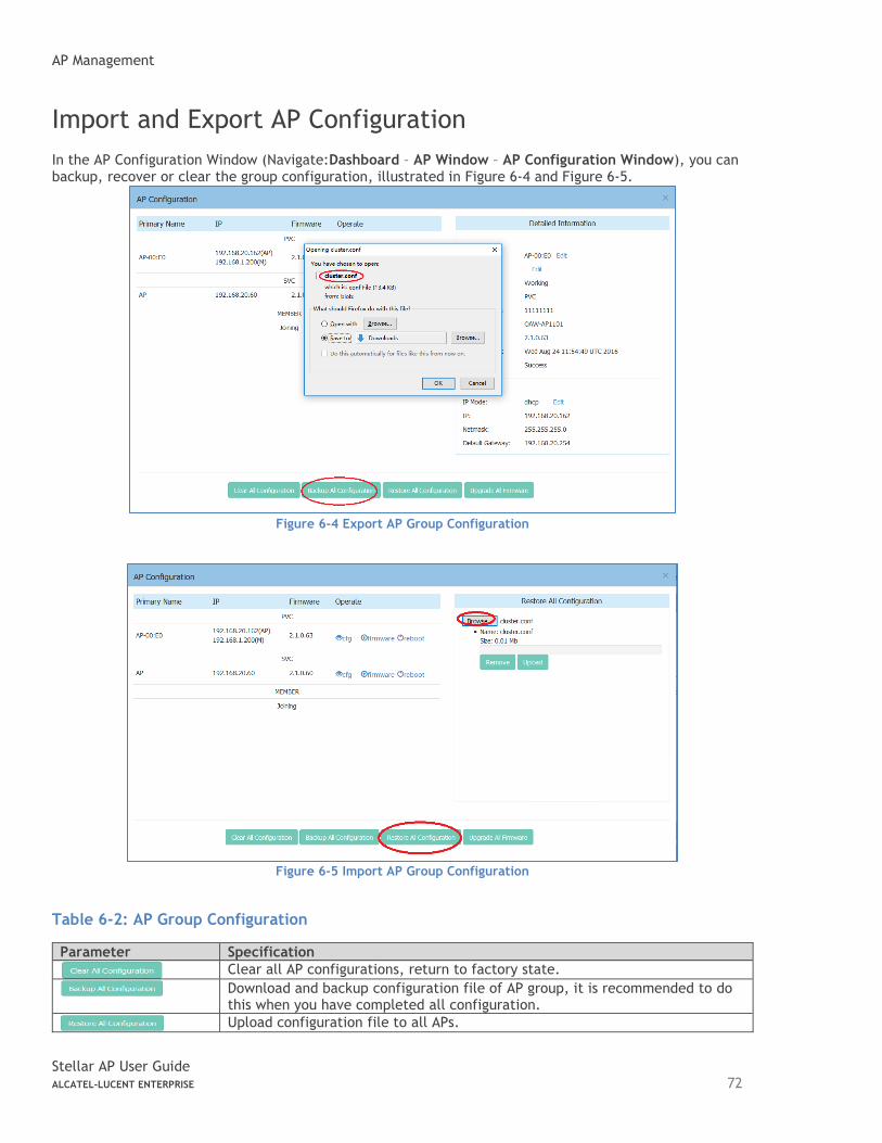
AP Management
Stellar AP User Guide ALCATEL-LUCENT ENTERPRISE 72
Import and Export AP Configuration
In the AP Configuration Window (Navigate:Dashboard – AP Window – AP Configuration Window), you can backup, recover or clear the group configuration, illustrated in Figure 6-4 and Figure 6-5.
Figure 6-4 Export AP Group Configuration
Figure 6-5 Import AP Group Configuration
Table 6-2: AP Group Configuration
Parameter Specification
Clear all AP configurations, return to factory state.
Download and backup configuration file of AP group, it is recommended to do this when you have completed all configuration.
Upload configuration file to all APs.
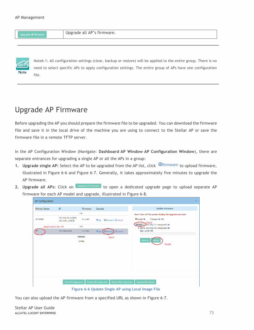
AP Management
Stellar AP User Guide ALCATEL-LUCENT ENTERPRISE 73
Upgrade all AP’s firmware.
Note6-1: All configuration settings (clear, backup or restore) will be applied to the entire group. There is no
need to select specific APs to apply configuration settings. The entire group of APs have one configuration
file.
Upgrade AP Firmware
Before upgrading the AP you should prepare the firmware file to be upgraded. You can download the firmware
file and save it in the local drive of the machine you are using to connect to the Stellar AP or save the
firmware file in a remote TFTP server.
In the AP Configuration Window (Navigate: Dashboard–AP Window–AP Configuration Window), there are
separate entrances for upgrading a single AP or all the APs in a group:
1. Upgrade single AP: Select the AP to be upgraded from the AP list, click to upload firmware,
illustrated in Figure 6-6 and Figure 6-7. Generally, it takes approximately five minutes to upgrade the
AP firmware.
2. Upgrade all APs: Click on to open a dedicated upgrade page to upload separate AP
firmware for each AP model and upgrade, illustrated in Figure 6-8.
Figure 6-6 Update Single AP using Local Image File
You can also upload the AP firmware from a specified URL as shown in Figure 6-7.
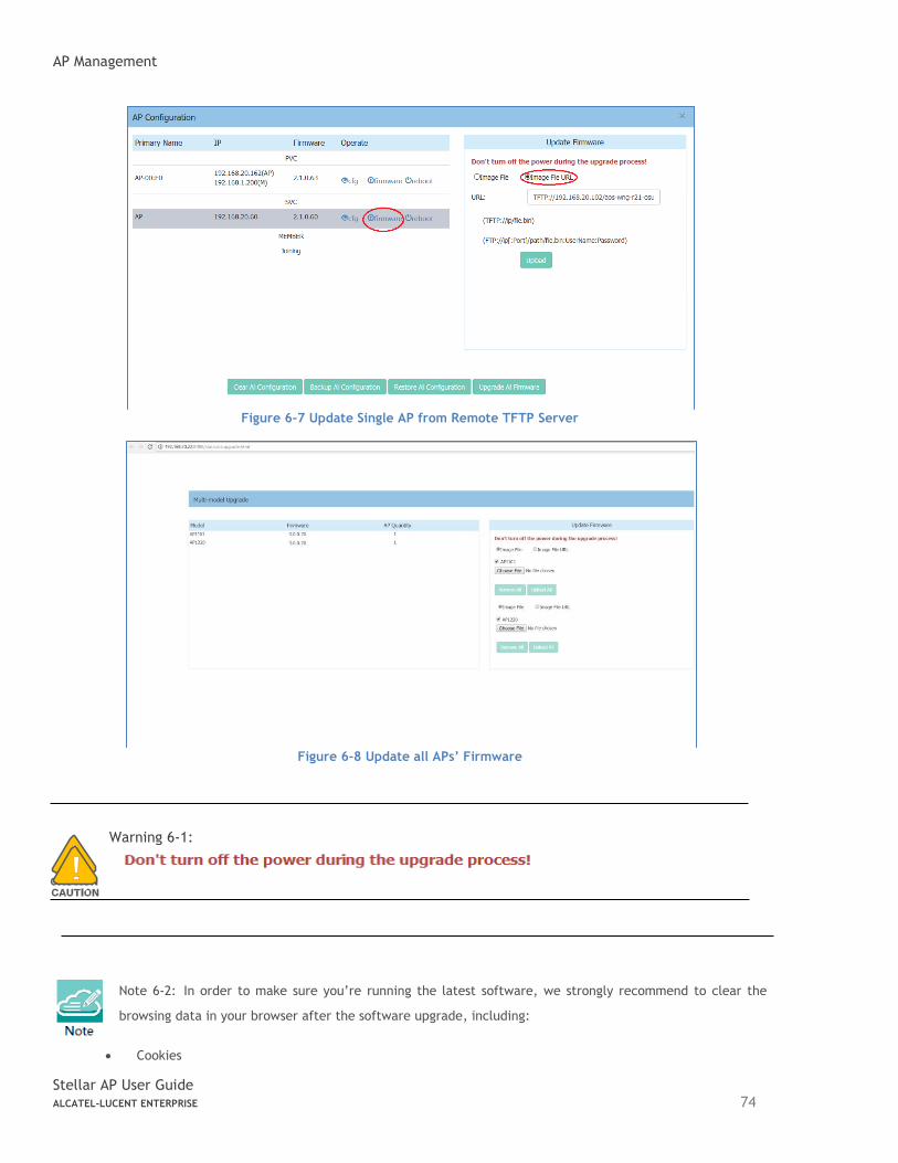
AP Management
Stellar AP User Guide ALCATEL-LUCENT ENTERPRISE 74
Figure 6-7 Update Single AP from Remote TFTP Server
Figure 6-8 Update all APs’ Firmware
Warning 6-1:
Note 6-2: In order to make sure you’re running the latest software, we strongly recommend to clear the
browsing data in your browser after the software upgrade, including:
• Cookies
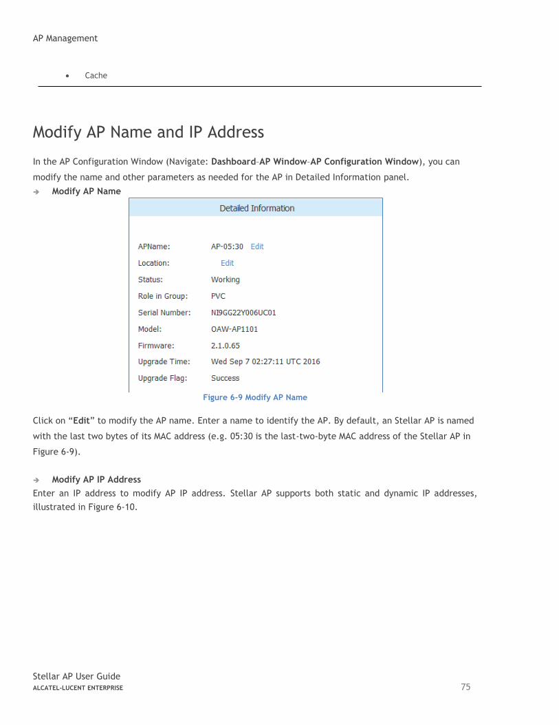
AP Management
Stellar AP User Guide ALCATEL-LUCENT ENTERPRISE 75
• Cache
Modify AP Name and IP Address
In the AP Configuration Window (Navigate: Dashboard–AP Window–AP Configuration Window), you can
modify the name and other parameters as needed for the AP in Detailed Information panel.
➔ Modify AP Name
Figure 6-9 Modify AP Name
Click on “Edit” to modify the AP name. Enter a name to identify the AP. By default, an Stellar AP is named
with the last two bytes of its MAC address (e.g. 05:30 is the last-two-byte MAC address of the Stellar AP in
Figure 6-9).
➔ Modify AP IP Address
Enter an IP address to modify AP IP address. Stellar AP supports both static and dynamic IP addresses,
illustrated in Figure 6-10.
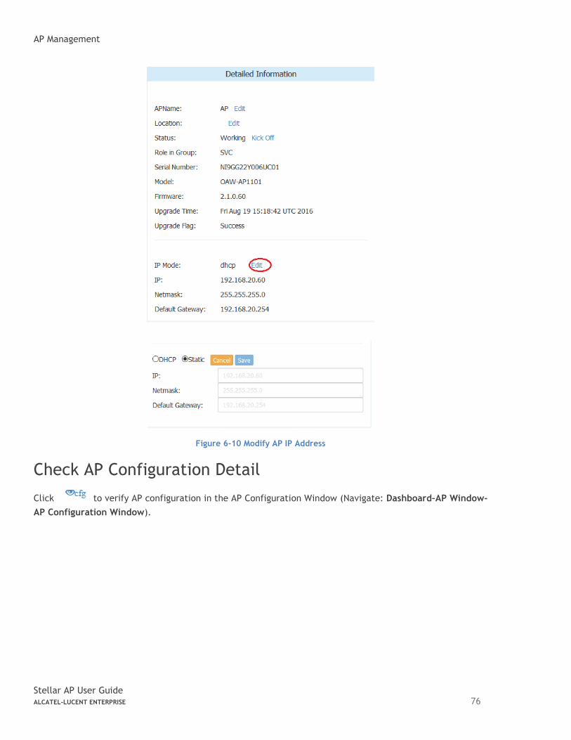
AP Management
Stellar AP User Guide ALCATEL-LUCENT ENTERPRISE 76
Figure 6-10 Modify AP IP Address
Check AP Configuration Detail
Click to verify AP configuration in the AP Configuration Window (Navigate: Dashboard–AP Window-
AP Configuration Window).
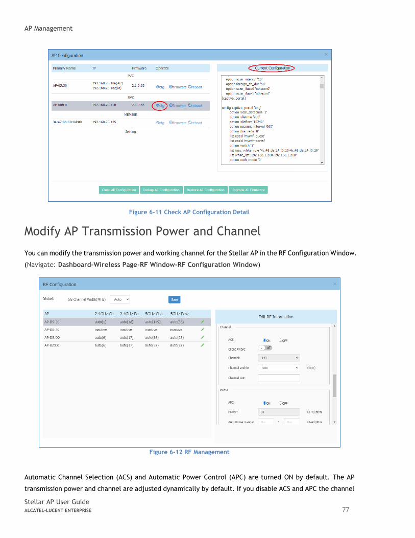
AP Management
Stellar AP User Guide ALCATEL-LUCENT ENTERPRISE 77
Figure 6-11 Check AP Configuration Detail
Modify AP Transmission Power and Channel
You can modify the transmission power and working channel for the Stellar AP in the RF Configuration Window.
(Navigate: Dashboard-Wireless Page-RF Window-RF Configuration Window)
Figure 6-12 RF Management
Automatic Channel Selection (ACS) and Automatic Power Control (APC) are turned ON by default. The AP
transmission power and channel are adjusted dynamically by default. If you disable ACS and APC the channel
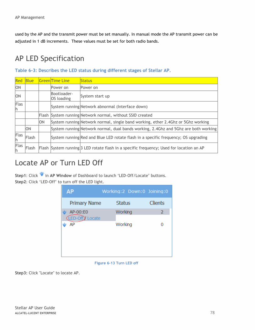
AP Management
Stellar AP User Guide ALCATEL-LUCENT ENTERPRISE 78
used by the AP and the transmit power must be set manually. In manual mode the AP transmit power can be
adjusted in 1 dB increments. These values must be set for both radio bands.
AP LED Specification
Table 6-3: Describes the LED status during different stages of Stellar AP.
Red Blue Green Time Line Status
ON Power on Power on
ON Bootloader-OS loading
System start up
Flash
System running Network abnormal (Interface down)
Flash System running Network normal, without SSID created
ON System running Network normal, single band working, ether 2.4Ghz or 5Ghz working
ON System running Network normal, dual bands working, 2.4Ghz and 5Ghz are both working
Flash
Flash System running Red and Blue LED rotate flash in a specific frequency; OS upgrading
Flash
Flash Flash System running 3 LED rotate flash in a specific frequency; Used for location an AP
Locate AP or Turn LED Off
Step1: Click in AP Window of Dashboard to launch ‘LED-Off/Locate’ buttons.
Step2: Click ‘LED-Off’ to turn off the LED light.
Figure 6-13 Turn LED off
Step3: Click "Locate" to locate AP.
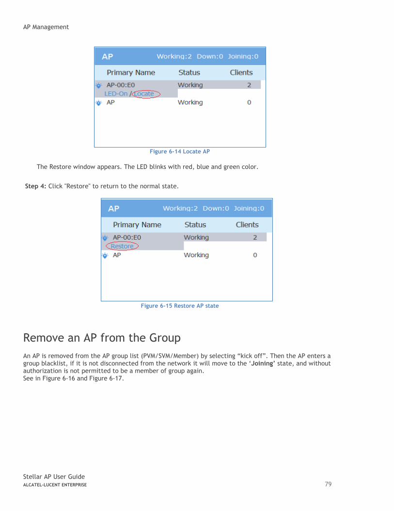
AP Management
Stellar AP User Guide ALCATEL-LUCENT ENTERPRISE 79
Figure 6-14 Locate AP
The Restore window appears. The LED blinks with red, blue and green color.
Step 4: Click "Restore" to return to the normal state.
Figure 6-15 Restore AP state
Remove an AP from the Group
An AP is removed from the AP group list (PVM/SVM/Member) by selecting “kick off”. Then the AP enters a group blacklist, if it is not disconnected from the network it will move to the ‘Joining’ state, and without authorization is not permitted to be a member of group again. See in Figure 6-16 and Figure 6-17.
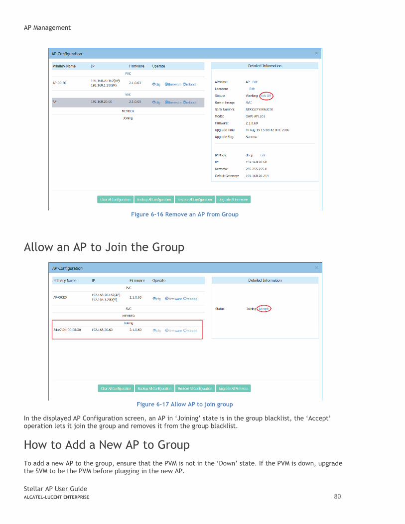
AP Management
Stellar AP User Guide ALCATEL-LUCENT ENTERPRISE 80
Figure 6-16 Remove an AP from Group
Allow an AP to Join the Group
Figure 6-17 Allow AP to join group
In the displayed AP Configuration screen, an AP in ‘Joining’ state is in the group blacklist, the ‘Accept’ operation lets it join the group and removes it from the group blacklist.
How to Add a New AP to Group
To add a new AP to the group, ensure that the PVM is not in the ‘Down’ state. If the PVM is down, upgrade the SVM to be the PVM before plugging in the new AP.
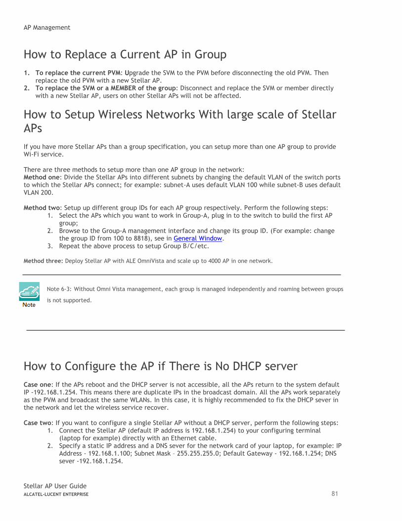
AP Management
Stellar AP User Guide ALCATEL-LUCENT ENTERPRISE 81
How to Replace a Current AP in Group
1. To replace the current PVM: Upgrade the SVM to the PVM before disconnecting the old PVM. Then replace the old PVM with a new Stellar AP.
2. To replace the SVM or a MEMBER of the group: Disconnect and replace the SVM or member directly with a new Stellar AP, users on other Stellar APs will not be affected.
How to Setup Wireless Networks With large scale of Stellar APs
If you have more Stellar APs than a group specification, you can setup more than one AP group to provide Wi-Fi service. There are three methods to setup more than one AP group in the network: Method one: Divide the Stellar APs into different subnets by changing the default VLAN of the switch ports to which the Stellar APs connect; for example: subnet-A uses default VLAN 100 while subnet-B uses default VLAN 200. Method two: Setup up different group IDs for each AP group respectively. Perform the following steps:
1. Select the APs which you want to work in Group-A, plug in to the switch to build the first AP group;
2. Browse to the Group-A management interface and change its group ID. (For example: change the group ID from 100 to 8818), see in General Window.
3. Repeat the above process to setup Group B/C/etc. Method three: Deploy Stellar AP with ALE OmniVista and scale up to 4000 AP in one network.
Note 6-3: Without Omni Vista management, each group is managed independently and roaming between groups
is not supported.
How to Configure the AP if There is No DHCP server
Case one: If the APs reboot and the DHCP server is not accessible, all the APs return to the system default IP -192.168.1.254. This means there are duplicate IPs in the broadcast domain. All the APs work separately as the PVM and broadcast the same WLANs. In this case, it is highly recommended to fix the DHCP sever in the network and let the wireless service recover. Case two: If you want to configure a single Stellar AP without a DHCP server, perform the following steps:
1. Connect the Stellar AP (default IP address is 192.168.1.254) to your configuring terminal (laptop for example) directly with an Ethernet cable.
2. Specify a static IP address and a DNS sever for the network card of your laptop, for example: IP Address - 192.168.1.100; Subnet Mask – 255.255.255.0; Default Gateway - 192.168.1.254; DNS sever -192.168.1.254.
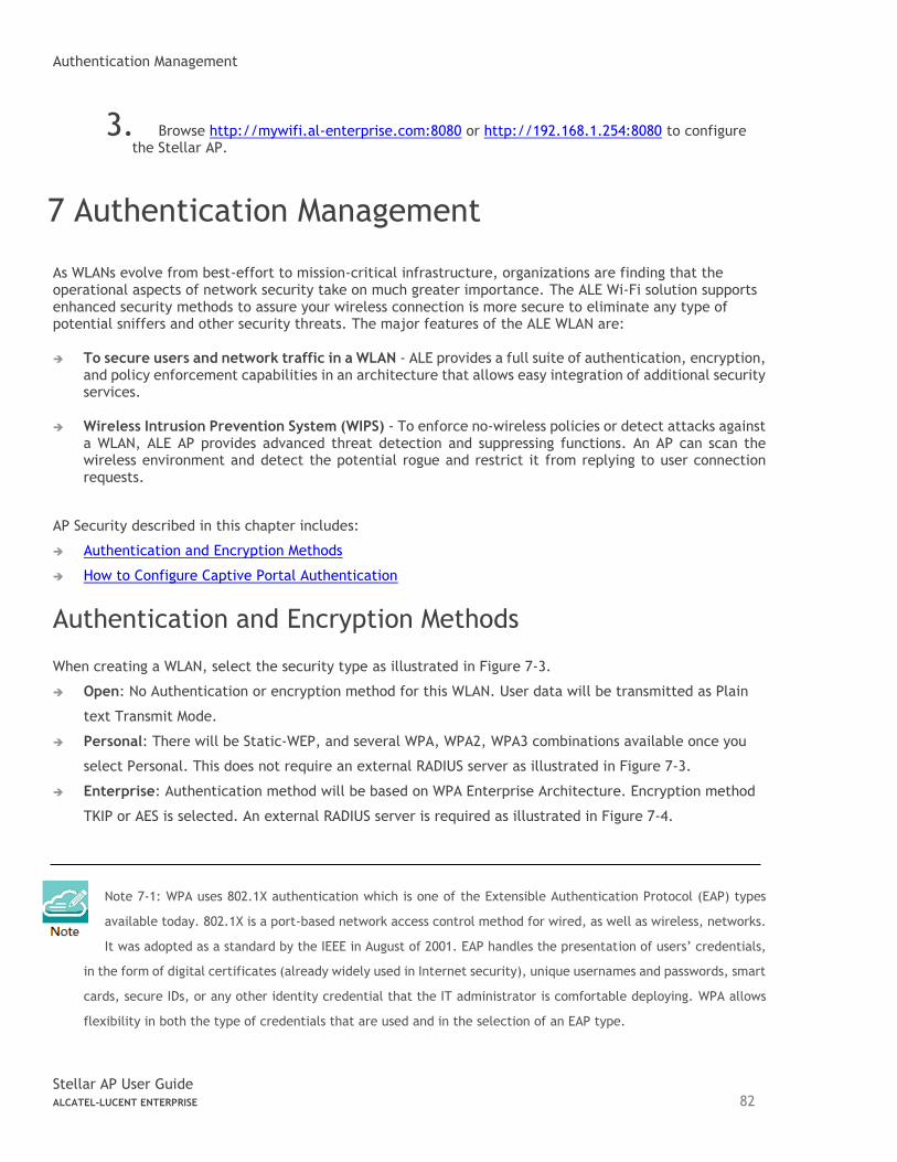
Authentication Management
Stellar AP User Guide ALCATEL-LUCENT ENTERPRISE 82
3. Browse http://mywifi.al-enterprise.com:8080 or http://192.168.1.254:8080 to configure the Stellar AP.
7 Authentication Management
As WLANs evolve from best-effort to mission-critical infrastructure, organizations are finding that the operational aspects of network security take on much greater importance. The ALE Wi-Fi solution supports enhanced security methods to assure your wireless connection is more secure to eliminate any type of potential sniffers and other security threats. The major features of the ALE WLAN are: ➔ To secure users and network traffic in a WLAN - ALE provides a full suite of authentication, encryption,
and policy enforcement capabilities in an architecture that allows easy integration of additional security services.
➔ Wireless Intrusion Prevention System (WIPS) - To enforce no-wireless policies or detect attacks against a WLAN, ALE AP provides advanced threat detection and suppressing functions. An AP can scan the wireless environment and detect the potential rogue and restrict it from replying to user connection requests.
AP Security described in this chapter includes:
➔ Authentication and Encryption Methods
➔ How to Configure Captive Portal Authentication
Authentication and Encryption Methods
When creating a WLAN, select the security type as illustrated in Figure 7-3.
➔ Open: No Authentication or encryption method for this WLAN. User data will be transmitted as Plain
text Transmit Mode.
➔ Personal: There will be Static-WEP, and several WPA, WPA2, WPA3 combinations available once you
select Personal. This does not require an external RADIUS server as illustrated in Figure 7-3.
➔ Enterprise: Authentication method will be based on WPA Enterprise Architecture. Encryption method
TKIP or AES is selected. An external RADIUS server is required as illustrated in Figure 7-4.
Note 7-1: WPA uses 802.1X authentication which is one of the Extensible Authentication Protocol (EAP) types
available today. 802.1X is a port-based network access control method for wired, as well as wireless, networks.
It was adopted as a standard by the IEEE in August of 2001. EAP handles the presentation of users’ credentials,
in the form of digital certificates (already widely used in Internet security), unique usernames and passwords, smart
cards, secure IDs, or any other identity credential that the IT administrator is comfortable deploying. WPA allows
flexibility in both the type of credentials that are used and in the selection of an EAP type.
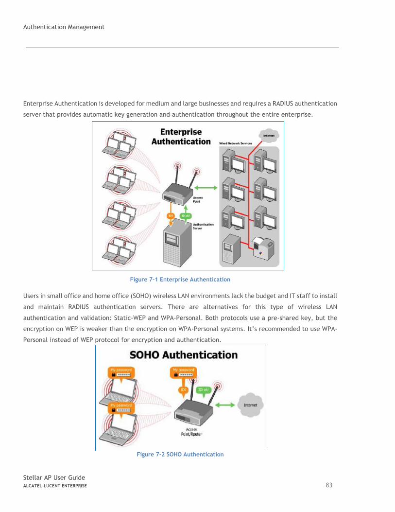
Authentication Management
Stellar AP User Guide ALCATEL-LUCENT ENTERPRISE 83
Enterprise Authentication is developed for medium and large businesses and requires a RADIUS authentication
server that provides automatic key generation and authentication throughout the entire enterprise.
Figure 7-1 Enterprise Authentication
Users in small office and home office (SOHO) wireless LAN environments lack the budget and IT staff to install
and maintain RADIUS authentication servers. There are alternatives for this type of wireless LAN
authentication and validation: Static-WEP and WPA-Personal. Both protocols use a pre-shared key, but the
encryption on WEP is weaker than the encryption on WPA-Personal systems. It’s recommended to use WPA-
Personal instead of WEP protocol for encryption and authentication.
Figure 7-2 SOHO Authentication
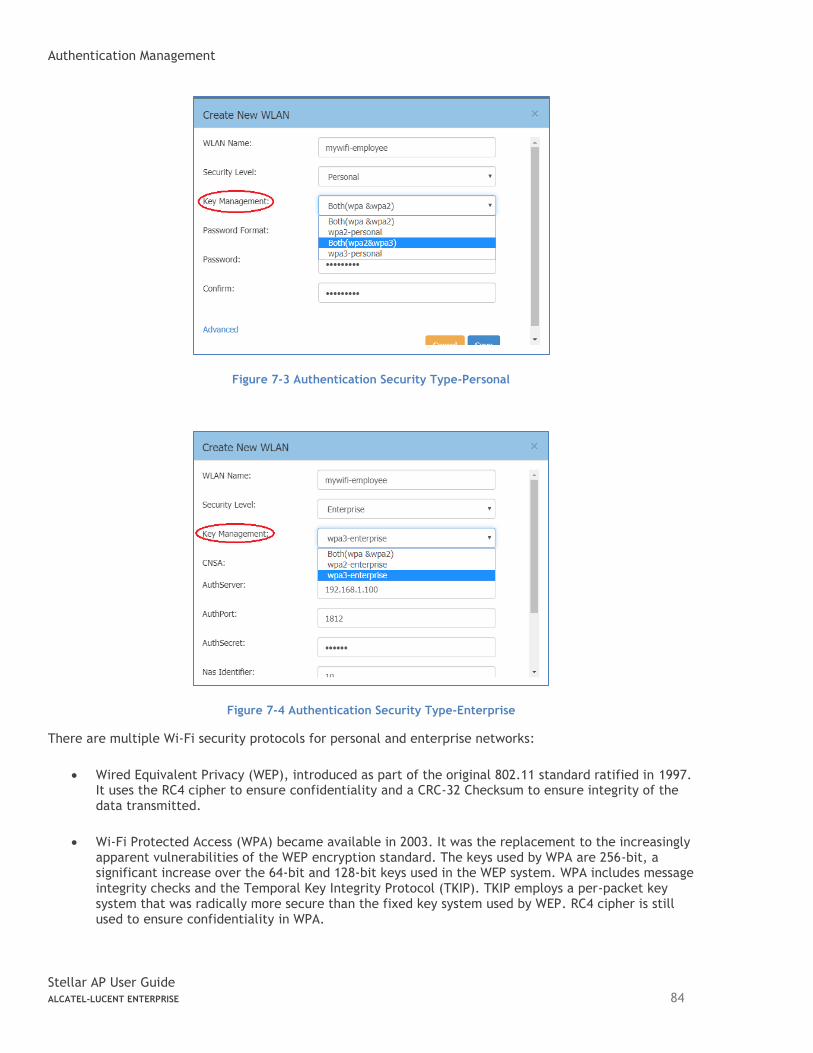
Authentication Management
Stellar AP User Guide ALCATEL-LUCENT ENTERPRISE 84
Figure 7-3 Authentication Security Type-Personal
Figure 7-4 Authentication Security Type-Enterprise
There are multiple Wi-Fi security protocols for personal and enterprise networks:
• Wired Equivalent Privacy (WEP), introduced as part of the original 802.11 standard ratified in 1997. It uses the RC4 cipher to ensure confidentiality and a CRC-32 Checksum to ensure integrity of the data transmitted.
• Wi-Fi Protected Access (WPA) became available in 2003. It was the replacement to the increasingly apparent vulnerabilities of the WEP encryption standard. The keys used by WPA are 256-bit, a significant increase over the 64-bit and 128-bit keys used in the WEP system. WPA includes message integrity checks and the Temporal Key Integrity Protocol (TKIP). TKIP employs a per-packet key system that was radically more secure than the fixed key system used by WEP. RC4 cipher is still used to ensure confidentiality in WPA.
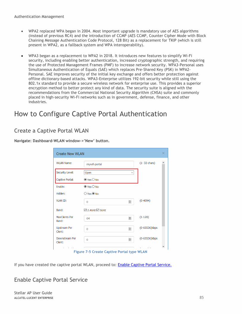
Authentication Management
Stellar AP User Guide ALCATEL-LUCENT ENTERPRISE 85
• WPA2 replaced WPA began in 2004. Most important upgrade is mandatory use of AES algorithms (instead of previous RC4) and the introduction of CCMP (AES CCMP, Counter Cipher Mode with Block Chaining Message Authentication Code Protocol, 128 Bit) as a replacement for TKIP (which is still present in WPA2, as a fallback system and WPA interoperability).
• WPA3 began as a replacement to WPA2 in 2018. It introduces new features to simplify Wi-Fi security, including enabling better authentication, increased cryptographic strength, and requiring the use of Protected Management Frames (PMF) to increase network security. WPA3-Personal uses Simultaneous Authentication of Equals (SAE) which replaces Pre-Shared Key (PSK) in WPA2-Personal. SAE improves security of the initial key exchange and offers better protection against offline dictionary-based attacks. WPA3-Enterprise utilizes 192-bit security while still using the 802.1x standard to provide a secure wireless network for enterprise use. This provides a superior encryption method to better protect any kind of data. The security suite is aligned with the recommendations from the Commercial National Security Algorithm (CNSA) suite and commonly placed in high-security Wi-Fi networks such as in government, defense, finance, and other industries.
How to Configure Captive Portal Authentication
Create a Captive Portal WLAN Navigate: Dashboard-WLAN window->’New’ button.
Figure 7-5 Create Captive Portal type WLAN
If you have created the captive portal WLAN, proceed to: Enable Captive Portal Service.
Enable Captive Portal Service
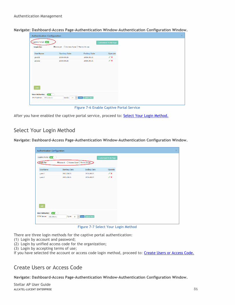
Authentication Management
Stellar AP User Guide ALCATEL-LUCENT ENTERPRISE 86
Navigate: Dashboard-Access Page-Authentication Window-Authentication Configuration Window.
Figure 7-6 Enable Captive Portal Service
After you have enabled the captive portal service, proceed to: Select Your Login Method.
Select Your Login Method Navigate: Dashboard-Access Page-Authentication Window-Authentication Configuration Window.
Figure 7-7 Select Your Login Method
There are three login methods for the captive portal authentication: (1) Login by account and password; (2) Login by unified access code for the organization; (3) Login by accepting terms of use; If you have selected the account or access code login method, proceed to: Create Users or Access Code.
Create Users or Access Code Navigate: Dashboard-Access Page-Authentication Window-Authentication Configuration Window.
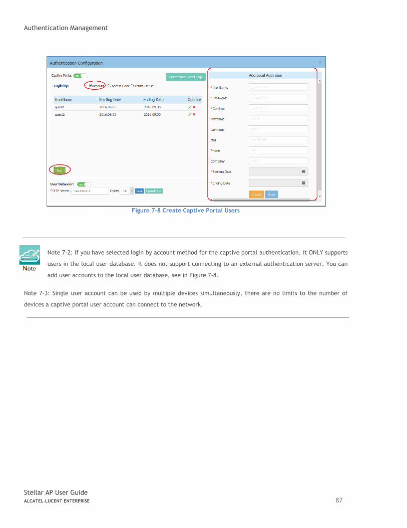
Authentication Management
Stellar AP User Guide ALCATEL-LUCENT ENTERPRISE 87
Figure 7-8 Create Captive Portal Users
Note 7-2: If you have selected login by account method for the captive portal authentication, it ONLY supports
users in the local user database. It does not support connecting to an external authentication server. You can
add user accounts to the local user database, see in Figure 7-8.
Note 7-3: Single user account can be used by multiple devices simultaneously, there are no limits to the number of
devices a captive portal user account can connect to the network.
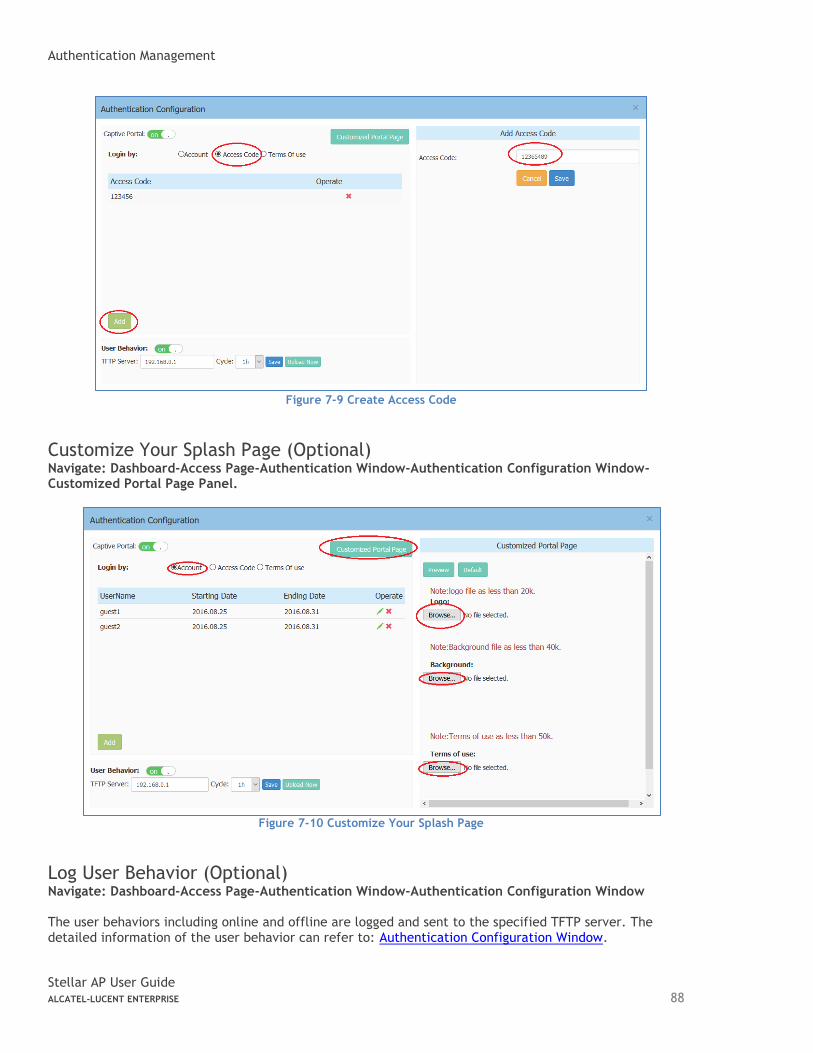
Authentication Management
Stellar AP User Guide ALCATEL-LUCENT ENTERPRISE 88
Figure 7-9 Create Access Code
Customize Your Splash Page (Optional) Navigate: Dashboard-Access Page-Authentication Window-Authentication Configuration Window-Customized Portal Page Panel.
Figure 7-10 Customize Your Splash Page
Log User Behavior (Optional) Navigate: Dashboard-Access Page-Authentication Window-Authentication Configuration Window The user behaviors including online and offline are logged and sent to the specified TFTP server. The detailed information of the user behavior can refer to: Authentication Configuration Window.
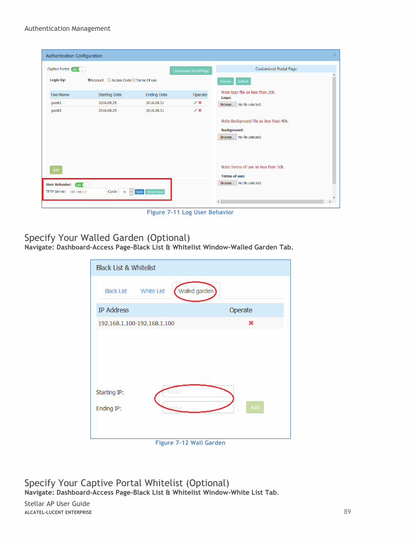
Authentication Management
Stellar AP User Guide ALCATEL-LUCENT ENTERPRISE 89
Figure 7-11 Log User Behavior
Specify Your Walled Garden (Optional) Navigate: Dashboard-Access Page-Black List & Whitelist Window-Walled Garden Tab.
Figure 7-12 Wall Garden
Specify Your Captive Portal Whitelist (Optional) Navigate: Dashboard-Access Page-Black List & Whitelist Window-White List Tab.
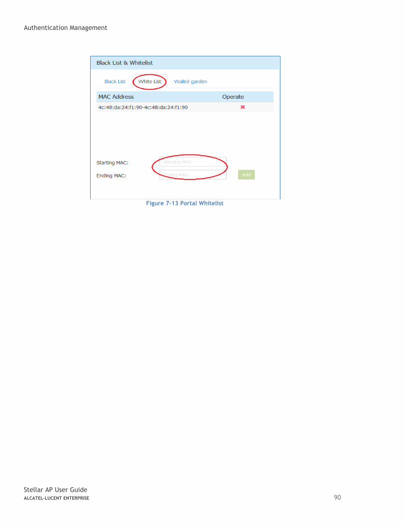
Authentication Management
Stellar AP User Guide ALCATEL-LUCENT ENTERPRISE 90
Figure 7-13 Portal Whitelist
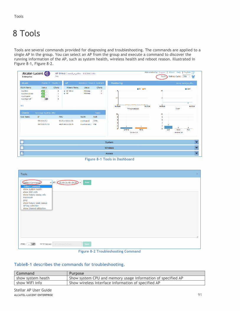
Tools
Stellar AP User Guide ALCATEL-LUCENT ENTERPRISE 91
8 Tools
Tools are several commands provided for diagnosing and troubleshooting. The commands are applied to a single AP in the group. You can select an AP from the group and execute a command to discover the running information of the AP, such as system health, wireless health and reboot reason. Illustrated in Figure 8-1, Figure 8-2.
Figure 8-1 Tools in Dashboard
Figure 8-2 Troubleshooting Command
Table8-1 describes the commands for troubleshooting.
Command Purpose
show system heath Show system CPU and memory usage information of specified AP
show WIFI info Show wireless interface information of specified AP
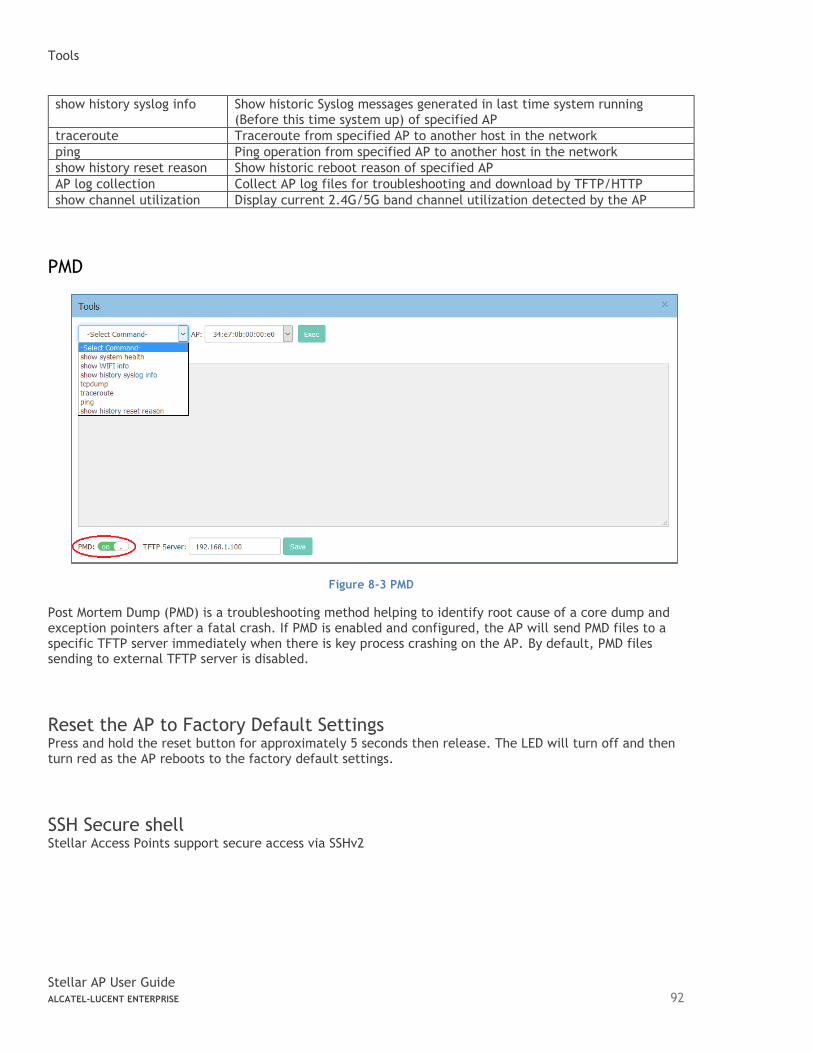
Tools
Stellar AP User Guide ALCATEL-LUCENT ENTERPRISE 92
show history syslog info Show historic Syslog messages generated in last time system running (Before this time system up) of specified AP
traceroute Traceroute from specified AP to another host in the network
ping Ping operation from specified AP to another host in the network
show history reset reason Show historic reboot reason of specified AP
AP log collection Collect AP log files for troubleshooting and download by TFTP/HTTP
show channel utilization Display current 2.4G/5G band channel utilization detected by the AP
PMD
Figure 8-3 PMD
Post Mortem Dump (PMD) is a troubleshooting method helping to identify root cause of a core dump and exception pointers after a fatal crash. If PMD is enabled and configured, the AP will send PMD files to a specific TFTP server immediately when there is key process crashing on the AP. By default, PMD files sending to external TFTP server is disabled.
Reset the AP to Factory Default Settings Press and hold the reset button for approximately 5 seconds then release. The LED will turn off and then turn red as the AP reboots to the factory default settings.
SSH Secure shell Stellar Access Points support secure access via SSHv2
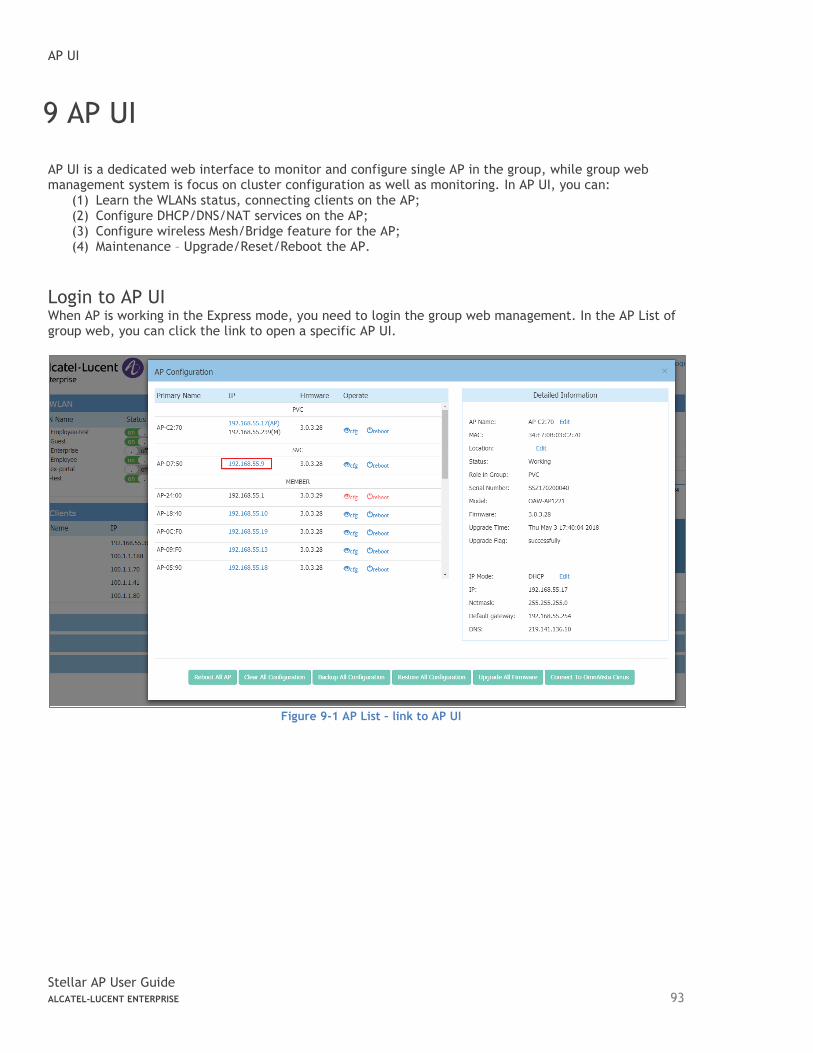
AP UI
Stellar AP User Guide ALCATEL-LUCENT ENTERPRISE 93
9 AP UI
AP UI is a dedicated web interface to monitor and configure single AP in the group, while group web management system is focus on cluster configuration as well as monitoring. In AP UI, you can:
(1) Learn the WLANs status, connecting clients on the AP; (2) Configure DHCP/DNS/NAT services on the AP; (3) Configure wireless Mesh/Bridge feature for the AP; (4) Maintenance – Upgrade/Reset/Reboot the AP.
Login to AP UI When AP is working in the Express mode, you need to login the group web management. In the AP List of group web, you can click the link to open a specific AP UI.
Figure 9-1 AP List – link to AP UI
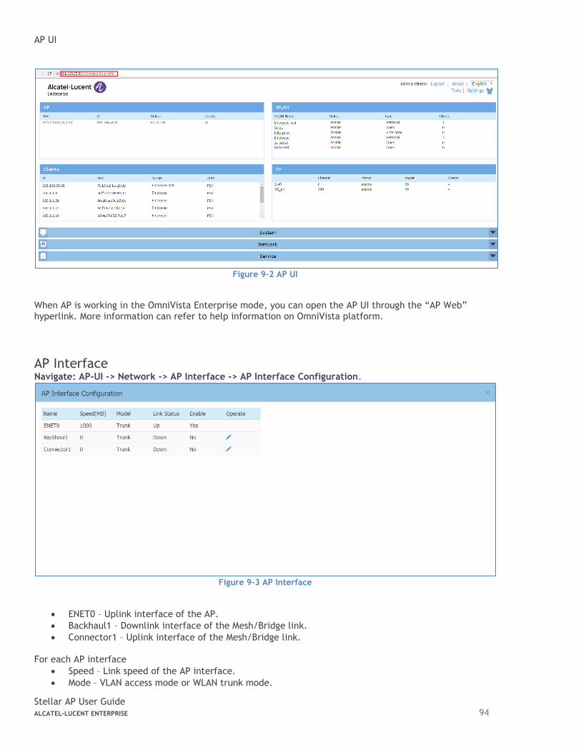
AP UI
Stellar AP User Guide ALCATEL-LUCENT ENTERPRISE 94
Figure 9-2 AP UI
When AP is working in the OmniVista Enterprise mode, you can open the AP UI through the “AP Web” hyperlink. More information can refer to help information on OmniVista platform.
AP Interface Navigate: AP-UI -> Network -> AP Interface -> AP Interface Configuration.
Figure 9-3 AP Interface
• ENET0 – Uplink interface of the AP.
• Backhaul1 – Downlink interface of the Mesh/Bridge link.
• Connector1 – Uplink interface of the Mesh/Bridge link. For each AP interface
• Speed – Link speed of the AP interface.
• Mode – VLAN access mode or WLAN trunk mode.
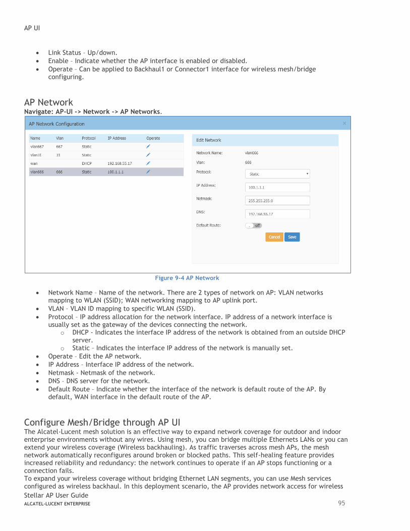
AP UI
Stellar AP User Guide ALCATEL-LUCENT ENTERPRISE 95
• Link Status – Up/down.
• Enable – Indicate whether the AP interface is enabled or disabled.
• Operate – Can be applied to Backhaul1 or Connector1 interface for wireless mesh/bridge configuring.
AP Network Navigate: AP-UI -> Network -> AP Networks.
Figure 9-4 AP Network
• Network Name – Name of the network. There are 2 types of network on AP: VLAN networks mapping to WLAN (SSID); WAN networking mapping to AP uplink port.
• VLAN – VLAN ID mapping to specific WLAN (SSID).
• Protocol – IP address allocation for the network interface. IP address of a network interface is usually set as the gateway of the devices connecting the network.
o DHCP - Indicates the interface IP address of the network is obtained from an outside DHCP server.
o Static – Indicates the interface IP address of the network is manually set.
• Operate – Edit the AP network.
• IP Address – Interface IP address of the network.
• Netmask - Netmask of the network.
• DNS – DNS server for the network.
• Default Route – Indicate whether the interface of the network is default route of the AP. By default, WAN interface in the default route of the AP.
Configure Mesh/Bridge through AP UI The Alcatel-Lucent mesh solution is an effective way to expand network coverage for outdoor and indoor enterprise environments without any wires. Using mesh, you can bridge multiple Ethernets LANs or you can extend your wireless coverage (Wireless backhauling). As traffic traverses across mesh APs, the mesh network automatically reconfigures around broken or blocked paths. This self-healing feature provides increased reliability and redundancy: the network continues to operate if an AP stops functioning or a connection fails. To expand your wireless coverage without bridging Ethernet LAN segments, you can use Mesh services configured as wireless backhaul. In this deployment scenario, the AP provides network access for wireless
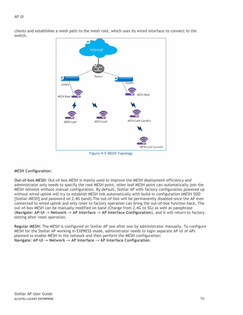
AP UI
Stellar AP User Guide ALCATEL-LUCENT ENTERPRISE 96
clients and establishes a mesh path to the mesh root, which uses its wired interface to connect to the switch.
Figure 9-5 MESH Topology
MESH Configuration: Out-of-box MESH: Out-of-box MESH is mainly used to improve the MESH deployment efficiency and administrator only needs to specify the root MESH point, other leaf MESH point can automatically join the MESH network without manual configuration. By default, Stellar AP with factory configuration powered up without wired uplink will try to establish MESH link automatically with build-in configuration (MESH SSID [Stellar-MESH] and password on 2.4G band).The out-of-box will be permanently disabled once the AP ever connected to wired uplink and only reset to factory operation can bring the out-of-box function back. The out-of-box MESH can be manually modified on band (Change from 2.4G to 5G) as well as passphrase (Navigate: AP-UI -> Network -> AP Interface -> AP Interface Configuration), and it will return to factory setting after reset operation. Regular MESH: The MESH is configured on Stellar AP one after one by administrator manually. To configure MESH for the Stellar AP working in EXPRESS mode, administrator needs to login separate AP-UI of APs planned to enable MESH in the network and then perform the MESH configuration: Navigate: AP-UI -> Network -> AP Interface -> AP Interface Configuration.
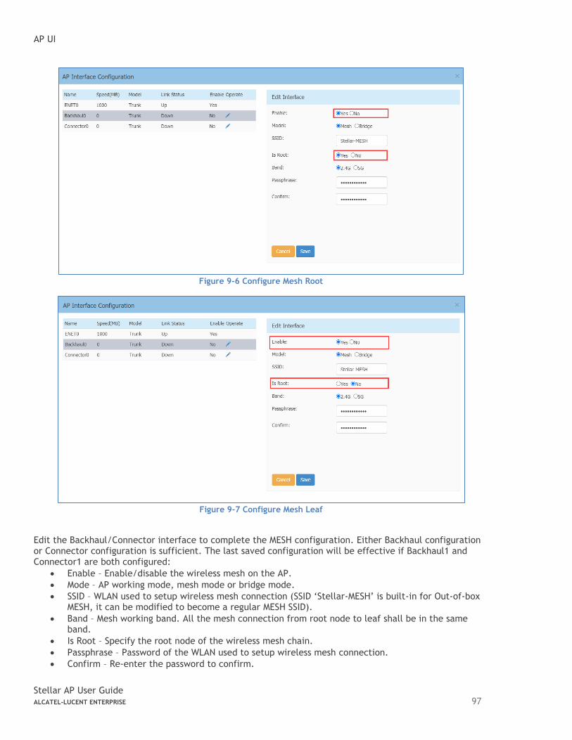
AP UI
Stellar AP User Guide ALCATEL-LUCENT ENTERPRISE 97
Figure 9-6 Configure Mesh Root
Figure 9-7 Configure Mesh Leaf
Edit the Backhaul/Connector interface to complete the MESH configuration. Either Backhaul configuration or Connector configuration is sufficient. The last saved configuration will be effective if Backhaul1 and Connector1 are both configured:
• Enable – Enable/disable the wireless mesh on the AP.
• Mode – AP working mode, mesh mode or bridge mode.
• SSID – WLAN used to setup wireless mesh connection (SSID ‘Stellar-MESH’ is built-in for Out-of-box MESH, it can be modified to become a regular MESH SSID).
• Band – Mesh working band. All the mesh connection from root node to leaf shall be in the same band.
• Is Root – Specify the root node of the wireless mesh chain.
• Passphrase – Password of the WLAN used to setup wireless mesh connection.
• Confirm – Re-enter the password to confirm.
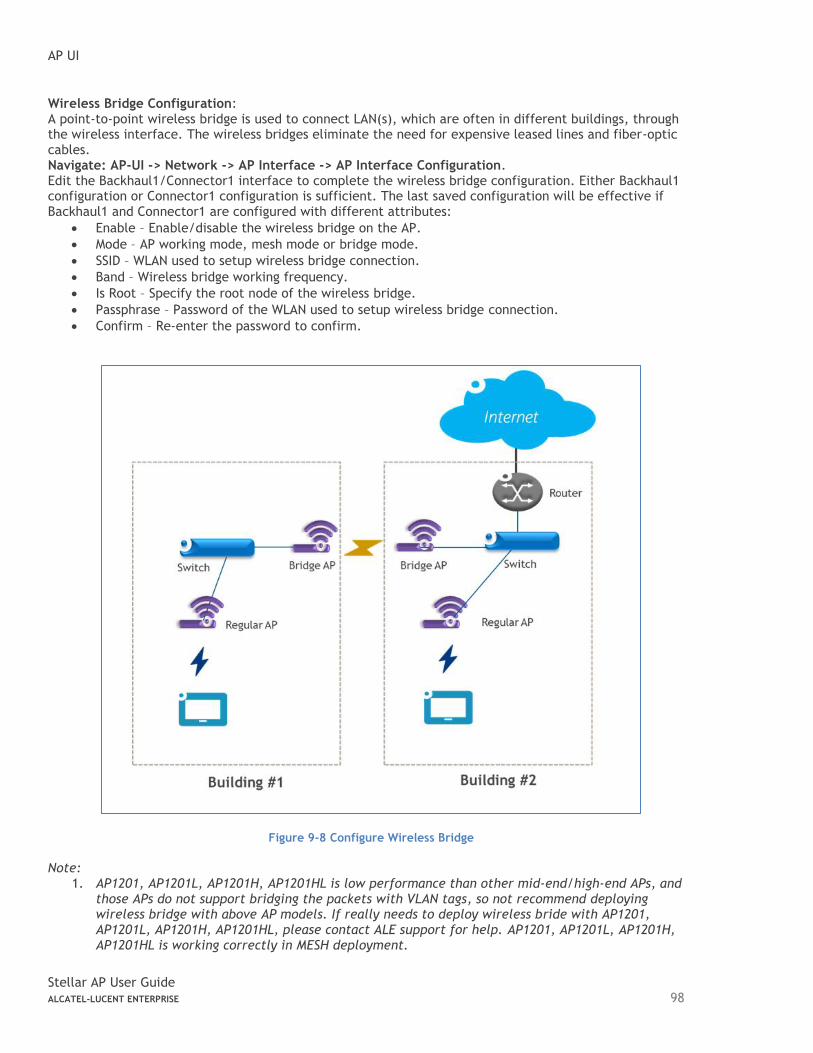
AP UI
Stellar AP User Guide ALCATEL-LUCENT ENTERPRISE 98
Wireless Bridge Configuration: A point-to-point wireless bridge is used to connect LAN(s), which are often in different buildings, through the wireless interface. The wireless bridges eliminate the need for expensive leased lines and fiber-optic cables. Navigate: AP-UI -> Network -> AP Interface -> AP Interface Configuration. Edit the Backhaul1/Connector1 interface to complete the wireless bridge configuration. Either Backhaul1 configuration or Connector1 configuration is sufficient. The last saved configuration will be effective if Backhaul1 and Connector1 are configured with different attributes:
• Enable – Enable/disable the wireless bridge on the AP.
• Mode – AP working mode, mesh mode or bridge mode.
• SSID – WLAN used to setup wireless bridge connection.
• Band – Wireless bridge working frequency.
• Is Root – Specify the root node of the wireless bridge.
• Passphrase – Password of the WLAN used to setup wireless bridge connection.
• Confirm – Re-enter the password to confirm.
Figure 9-8 Configure Wireless Bridge
Note:
1. AP1201, AP1201L, AP1201H, AP1201HL is low performance than other mid-end/high-end APs, and those APs do not support bridging the packets with VLAN tags, so not recommend deploying wireless bridge with above AP models. If really needs to deploy wireless bride with AP1201, AP1201L, AP1201H, AP1201HL, please contact ALE support for help. AP1201, AP1201L, AP1201H, AP1201HL is working correctly in MESH deployment.
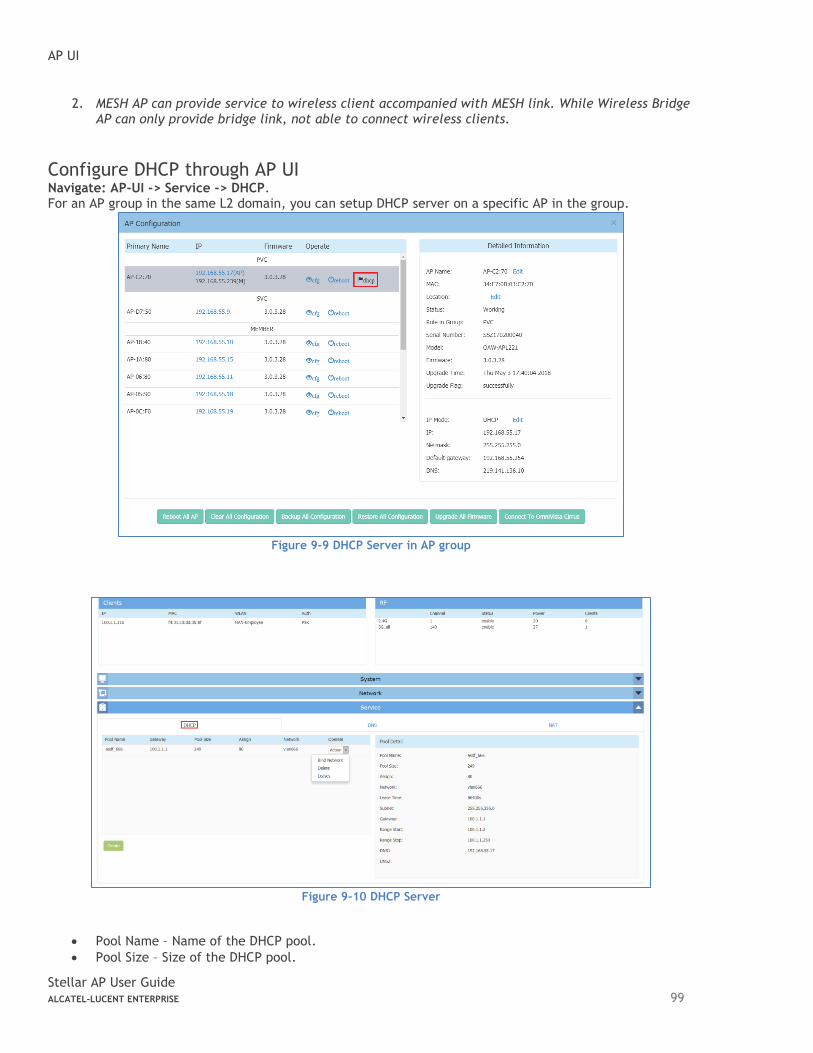
AP UI
Stellar AP User Guide ALCATEL-LUCENT ENTERPRISE 99
2. MESH AP can provide service to wireless client accompanied with MESH link. While Wireless Bridge AP can only provide bridge link, not able to connect wireless clients.
Configure DHCP through AP UI Navigate: AP-UI -> Service -> DHCP. For an AP group in the same L2 domain, you can setup DHCP server on a specific AP in the group.
Figure 9-9 DHCP Server in AP group
Figure 9-10 DHCP Server
• Pool Name – Name of the DHCP pool.
• Pool Size – Size of the DHCP pool.
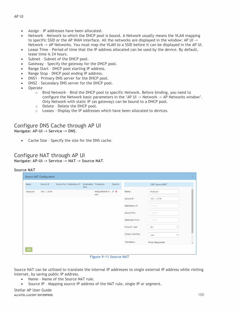
AP UI
Stellar AP User Guide ALCATEL-LUCENT ENTERPRISE 100
• Assign – IP addresses have been allocated.
• Network – Network to which the DHCP pool is bound. A Network usually means the VLAN mapping to specific SSID or the AP WAN interface. All the networks are displayed in the window: AP UI -> Network -> AP Networks. You must map the VLAN to a SSID before it can be displayed in the AP UI.
• Lease Time – Period of time that the IP address allocated can be used by the device. By default, lease time is 24 hours.
• Subnet – Subnet of the DHCP pool.
• Gateway – Specify the gateway for the DHCP pool.
• Range Start – DHCP pool starting IP address.
• Range Stop – DHCP pool ending IP address.
• DNS1 – Primary DNS server for the DHCP pool.
• DNS2 - Secondary DNS server for the DHCP pool.
• Operate o Bind Network – Bind the DHCP pool to specific Network. Before binding, you need to
configure the Network basic parameters in the ‘AP UI -> Network -> AP Networks window’. Only Network with static IP (as gateway) can be bound to a DHCP pool.
o Delete – Delete the DHCP pool. o Leases – Display the IP addresses which have been allocated to devices.
Configure DNS Cache through AP UI Navigate: AP-UI -> Service -> DNS.
• Cache Size – Specify the size for the DNS cache.
Configure NAT through AP UI Navigate: AP-UI -> Service -> NAT -> Source NAT. Source NAT
Figure 9-11 Source NAT
Source NAT can be utilized to translate the internal IP addresses to single external IP address while visiting Internet, by saving public IP address.
• Name – Name of the Source NAT rule.
• Source IP – Mapping source IP address of the NAT rule, single IP or segment.
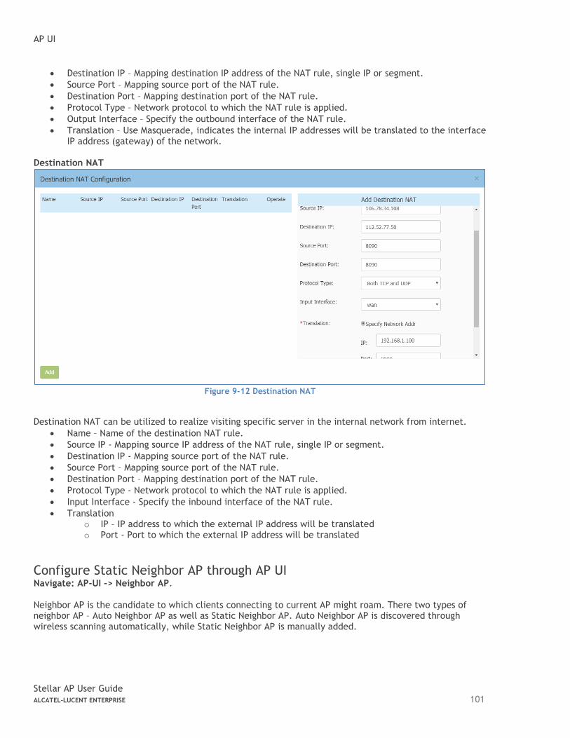
AP UI
Stellar AP User Guide ALCATEL-LUCENT ENTERPRISE 101
• Destination IP – Mapping destination IP address of the NAT rule, single IP or segment.
• Source Port – Mapping source port of the NAT rule.
• Destination Port – Mapping destination port of the NAT rule.
• Protocol Type – Network protocol to which the NAT rule is applied.
• Output Interface – Specify the outbound interface of the NAT rule.
• Translation – Use Masquerade, indicates the internal IP addresses will be translated to the interface IP address (gateway) of the network.
Destination NAT
Figure 9-12 Destination NAT
Destination NAT can be utilized to realize visiting specific server in the internal network from internet.
• Name – Name of the destination NAT rule.
• Source IP - Mapping source IP address of the NAT rule, single IP or segment.
• Destination IP - Mapping source port of the NAT rule.
• Source Port – Mapping source port of the NAT rule.
• Destination Port – Mapping destination port of the NAT rule.
• Protocol Type - Network protocol to which the NAT rule is applied.
• Input Interface - Specify the inbound interface of the NAT rule.
• Translation o IP – IP address to which the external IP address will be translated o Port - Port to which the external IP address will be translated
Configure Static Neighbor AP through AP UI Navigate: AP-UI -> Neighbor AP. Neighbor AP is the candidate to which clients connecting to current AP might roam. There two types of neighbor AP – Auto Neighbor AP as well as Static Neighbor AP. Auto Neighbor AP is discovered through wireless scanning automatically, while Static Neighbor AP is manually added.
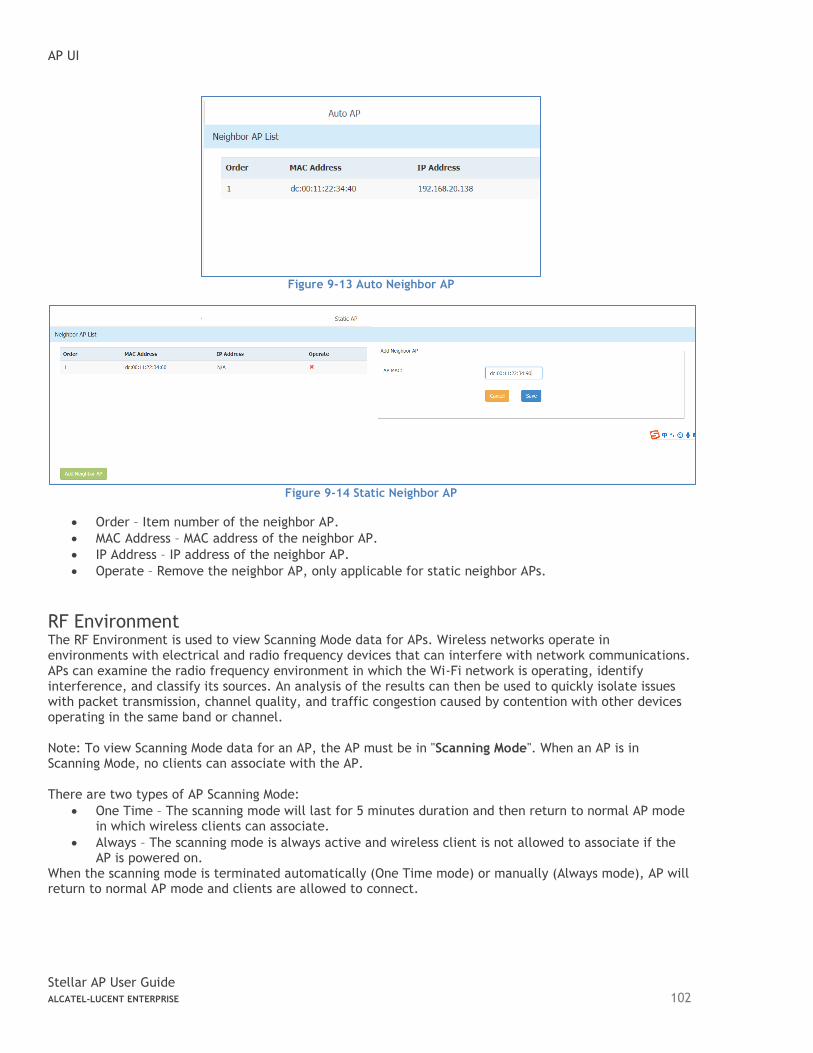
AP UI
Stellar AP User Guide ALCATEL-LUCENT ENTERPRISE 102
Figure 9-13 Auto Neighbor AP
Figure 9-14 Static Neighbor AP
• Order – Item number of the neighbor AP.
• MAC Address – MAC address of the neighbor AP.
• IP Address – IP address of the neighbor AP.
• Operate – Remove the neighbor AP, only applicable for static neighbor APs.
RF Environment The RF Environment is used to view Scanning Mode data for APs. Wireless networks operate in environments with electrical and radio frequency devices that can interfere with network communications. APs can examine the radio frequency environment in which the Wi-Fi network is operating, identify interference, and classify its sources. An analysis of the results can then be used to quickly isolate issues with packet transmission, channel quality, and traffic congestion caused by contention with other devices operating in the same band or channel. Note: To view Scanning Mode data for an AP, the AP must be in "Scanning Mode". When an AP is in Scanning Mode, no clients can associate with the AP. There are two types of AP Scanning Mode:
• One Time – The scanning mode will last for 5 minutes duration and then return to normal AP mode in which wireless clients can associate.
• Always – The scanning mode is always active and wireless client is not allowed to associate if the AP is powered on.
When the scanning mode is terminated automatically (One Time mode) or manually (Always mode), AP will return to normal AP mode and clients are allowed to connect.
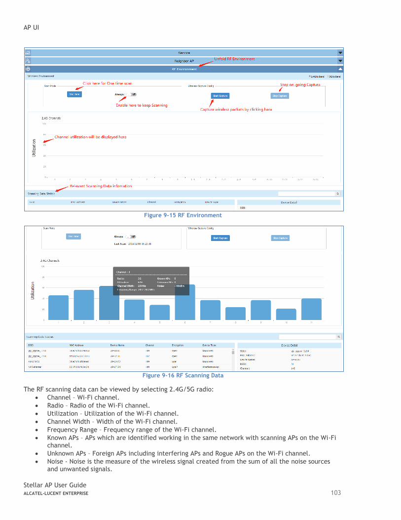
AP UI
Stellar AP User Guide ALCATEL-LUCENT ENTERPRISE 103
Figure 9-15 RF Environment
Figure 9-16 RF Scanning Data
The RF scanning data can be viewed by selecting 2.4G/5G radio:
• Channel – Wi-Fi channel.
• Radio – Radio of the Wi-Fi channel.
• Utilization – Utilization of the Wi-Fi channel.
• Channel Width – Width of the Wi-Fi channel.
• Frequency Range – Frequency range of the Wi-Fi channel.
• Known APs – APs which are identified working in the same network with scanning APs on the Wi-Fi channel.
• Unknown APs – Foreign APs including interfering APs and Rogue APs on the Wi-Fi channel.
• Noise - Noise is the measure of the wireless signal created from the sum of all the noise sources and unwanted signals.
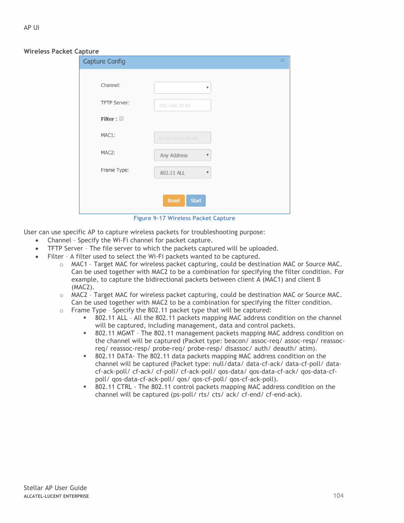
AP UI
Stellar AP User Guide ALCATEL-LUCENT ENTERPRISE 104
Wireless Packet Capture
Figure 9-17 Wireless Packet Capture
User can use specific AP to capture wireless packets for troubleshooting purpose:
• Channel – Specify the Wi-Fi channel for packet capture.
• TFTP Server – The file server to which the packets captured will be uploaded.
• Filter – A filter used to select the Wi-Fi packets wanted to be captured. o MAC1 – Target MAC for wireless packet capturing, could be destination MAC or Source MAC.
Can be used together with MAC2 to be a combination for specifying the filter condition. For example, to capture the bidirectional packets between client A (MAC1) and client B (MAC2).
o MAC2 – Target MAC for wireless packet capturing, could be destination MAC or Source MAC. Can be used together with MAC2 to be a combination for specifying the filter condition.
o Frame Type – Specify the 802.11 packet type that will be captured: ▪ 802.11 ALL – All the 802.11 packets mapping MAC address condition on the channel
will be captured, including management, data and control packets. ▪ 802.11 MGMT – The 802.11 management packets mapping MAC address condition on
the channel will be captured (Packet type: beacon/ assoc-req/ assoc-resp/ reassoc-req/ reassoc-resp/ probe-req/ probe-resp/ disassoc/ auth/ deauth/ atim).
▪ 802.11 DATA- The 802.11 data packets mapping MAC address condition on the channel will be captured (Packet type: null/data/ data-cf-ack/ data-cf-poll/ data-cf-ack-poll/ cf-ack/ cf-poll/ cf-ack-poll/ qos-data/ qos-data-cf-ack/ qos-data-cf-poll/ qos-data-cf-ack-poll/ qos/ qos-cf-poll/ qos-cf-ack-poll).
▪ 802.11 CTRL - The 802.11 control packets mapping MAC address condition on the channel will be captured (ps-poll/ rts/ cts/ ack/ cf-end/ cf-end-ack).
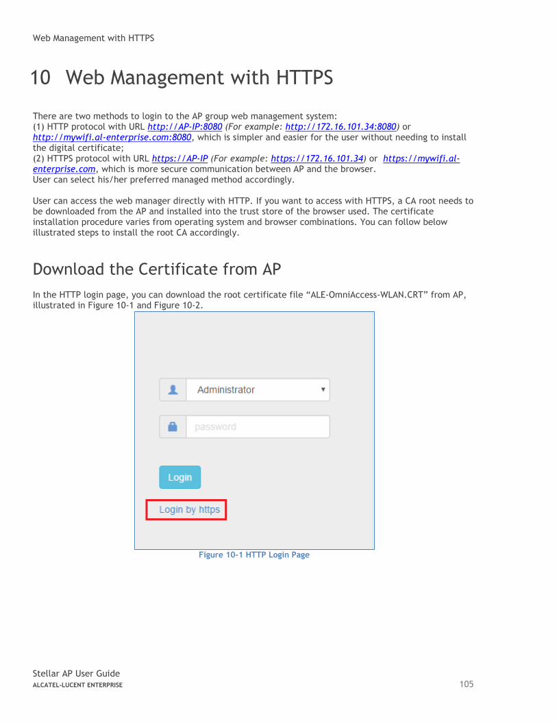
Web Management with HTTPS
Stellar AP User Guide ALCATEL-LUCENT ENTERPRISE 105
10 Web Management with HTTPS
There are two methods to login to the AP group web management system: (1) HTTP protocol with URL http://AP-IP:8080 (For example: http://172.16.101.34:8080) or http://mywifi.al-enterprise.com:8080, which is simpler and easier for the user without needing to install the digital certificate; (2) HTTPS protocol with URL https://AP-IP (For example: https://172.16.101.34) or https://mywifi.al-enterprise.com, which is more secure communication between AP and the browser. User can select his/her preferred managed method accordingly. User can access the web manager directly with HTTP. If you want to access with HTTPS, a CA root needs to be downloaded from the AP and installed into the trust store of the browser used. The certificate installation procedure varies from operating system and browser combinations. You can follow below illustrated steps to install the root CA accordingly.
Download the Certificate from AP
In the HTTP login page, you can download the root certificate file “ALE-OmniAccess-WLAN.CRT” from AP, illustrated in Figure 10-1 and Figure 10-2.
Figure 10-1 HTTP Login Page
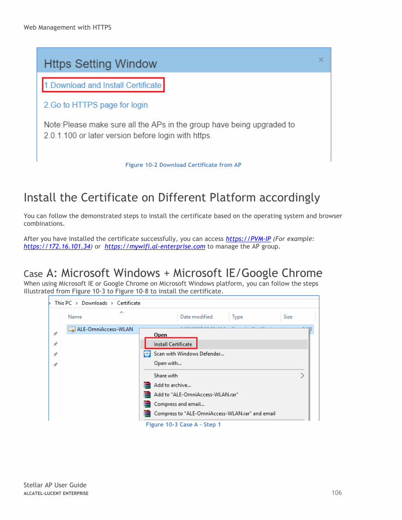
Web Management with HTTPS
Stellar AP User Guide ALCATEL-LUCENT ENTERPRISE 106
Figure 10-2 Download Certificate from AP
Install the Certificate on Different Platform accordingly
You can follow the demonstrated steps to install the certificate based on the operating system and browser combinations. After you have installed the certificate successfully, you can access https://PVM-IP (For example: https://172.16.101.34) or https://mywifi.al-enterprise.com to manage the AP group.
Case A: Microsoft Windows + Microsoft IE/Google Chrome When using Microsoft IE or Google Chrome on Microsoft Windows platform, you can follow the steps illustrated from Figure 10-3 to Figure 10-8 to install the certificate.
Figure 10-3 Case A – Step 1
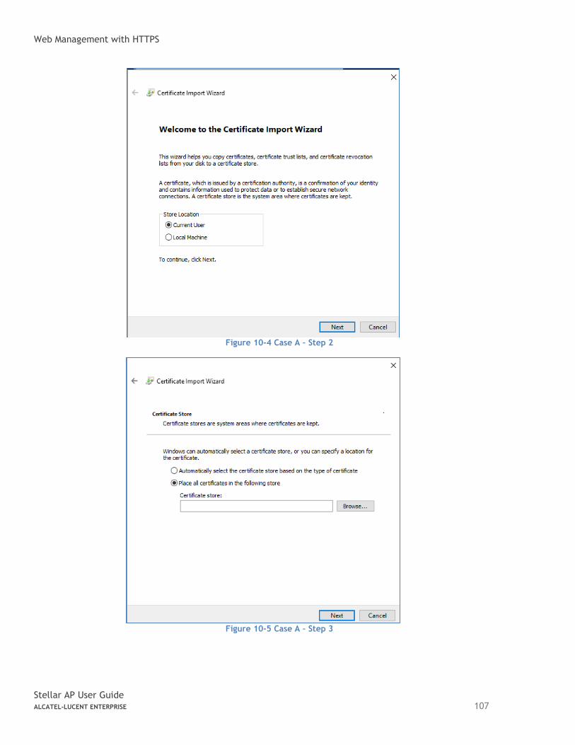
Web Management with HTTPS
Stellar AP User Guide ALCATEL-LUCENT ENTERPRISE 107
Figure 10-4 Case A – Step 2
Figure 10-5 Case A – Step 3
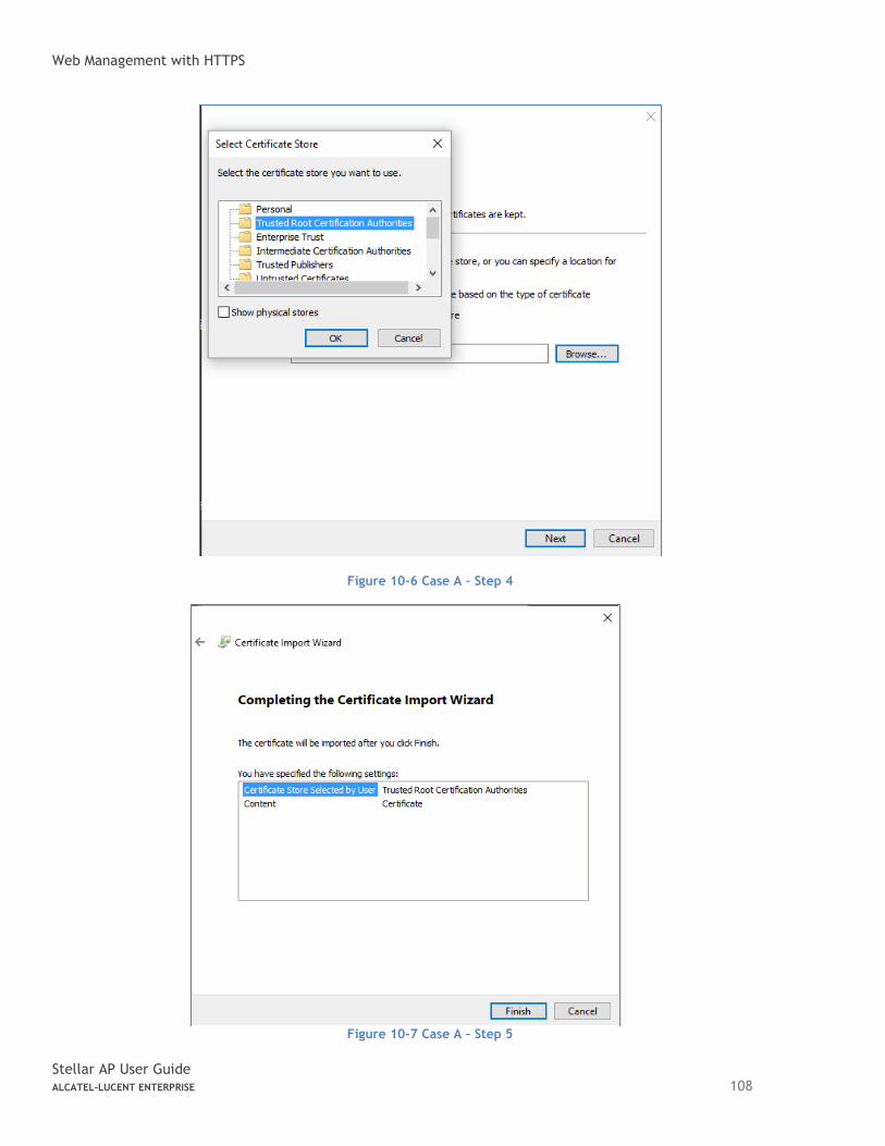
Web Management with HTTPS
Stellar AP User Guide ALCATEL-LUCENT ENTERPRISE 108
Figure 10-6 Case A – Step 4
Figure 10-7 Case A – Step 5
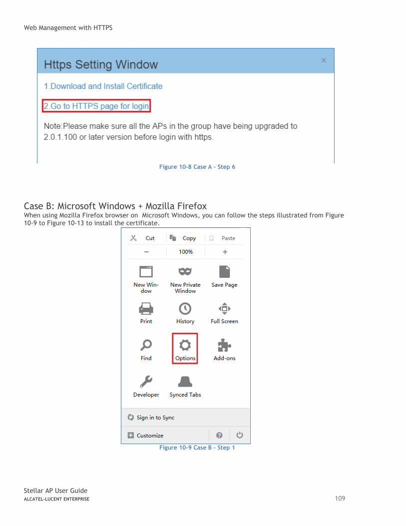
Web Management with HTTPS
Stellar AP User Guide ALCATEL-LUCENT ENTERPRISE 109
Figure 10-8 Case A – Step 6
Case B: Microsoft Windows + Mozilla Firefox When using Mozilla Firefox browser on Microsoft Windows, you can follow the steps illustrated from Figure 10-9 to Figure 10-13 to install the certificate.
Figure 10-9 Case B – Step 1
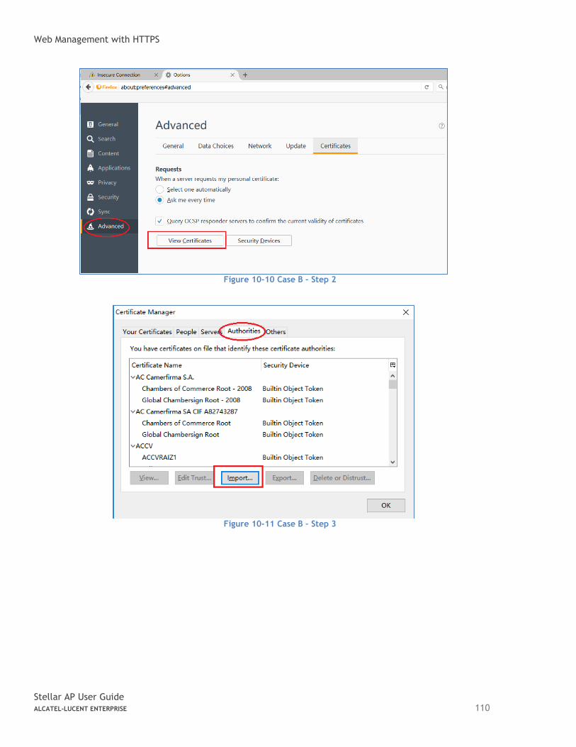
Web Management with HTTPS
Stellar AP User Guide ALCATEL-LUCENT ENTERPRISE 110
Figure 10-10 Case B – Step 2
Figure 10-11 Case B – Step 3
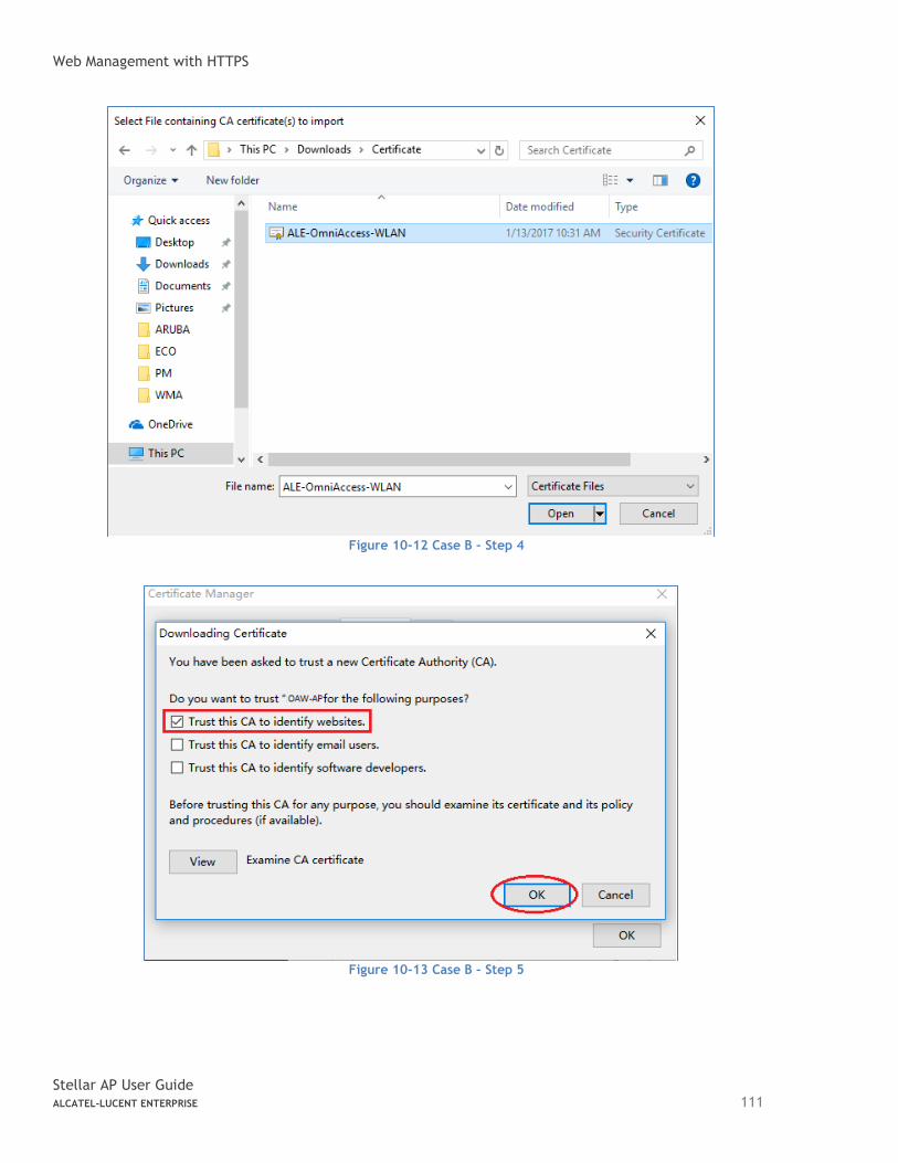
Web Management with HTTPS
Stellar AP User Guide ALCATEL-LUCENT ENTERPRISE 111
Figure 10-12 Case B – Step 4
Figure 10-13 Case B – Step 5
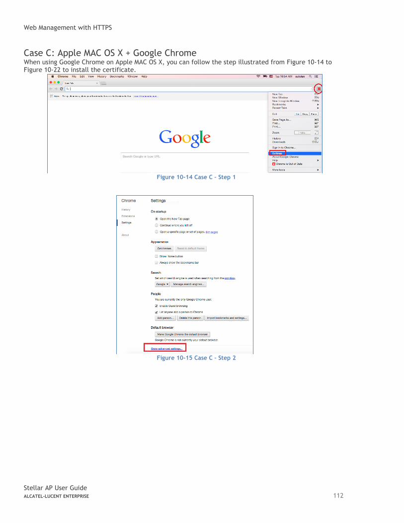
Web Management with HTTPS
Stellar AP User Guide ALCATEL-LUCENT ENTERPRISE 112
Case C: Apple MAC OS X + Google Chrome When using Google Chrome on Apple MAC OS X, you can follow the step illustrated from Figure 10-14 to Figure 10-22 to install the certificate.
Figure 10-14 Case C – Step 1
Figure 10-15 Case C – Step 2
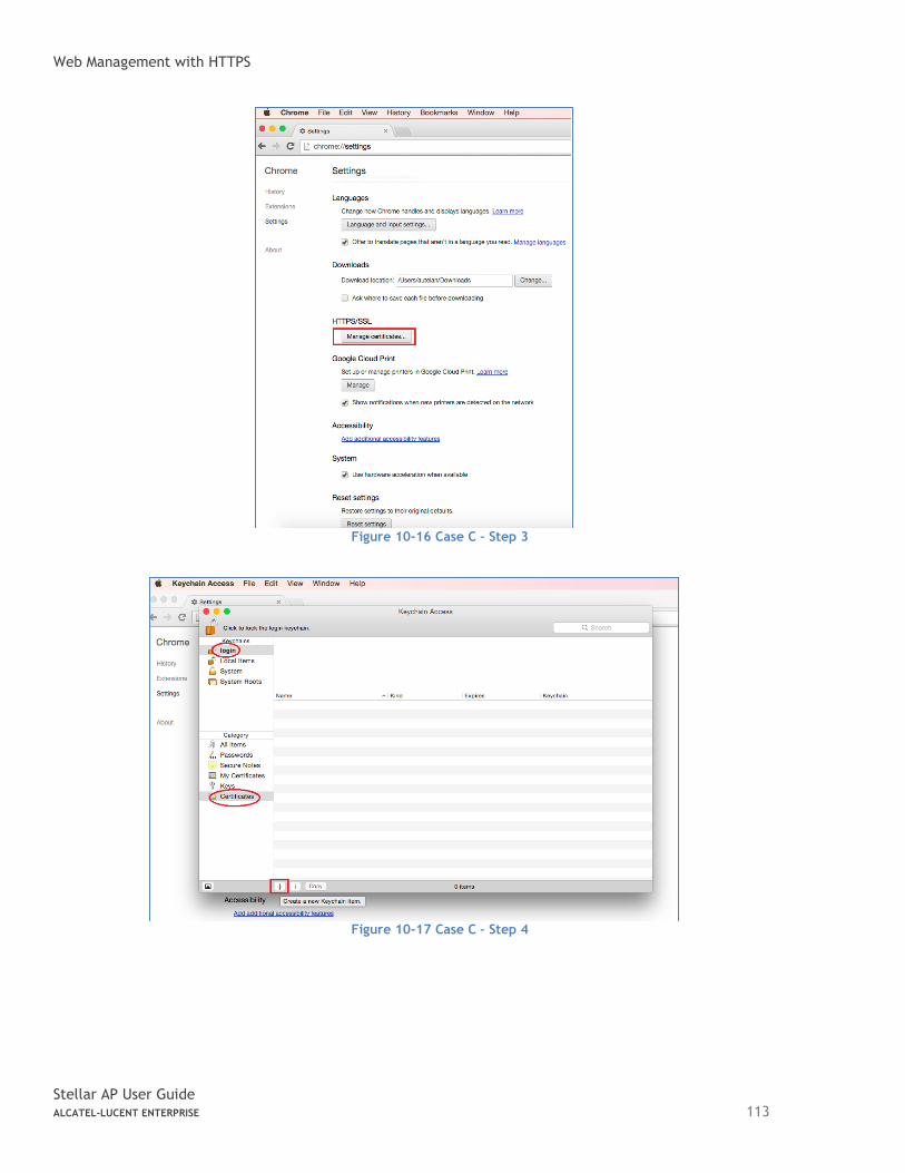
Web Management with HTTPS
Stellar AP User Guide ALCATEL-LUCENT ENTERPRISE 113
Figure 10-16 Case C – Step 3
Figure 10-17 Case C – Step 4
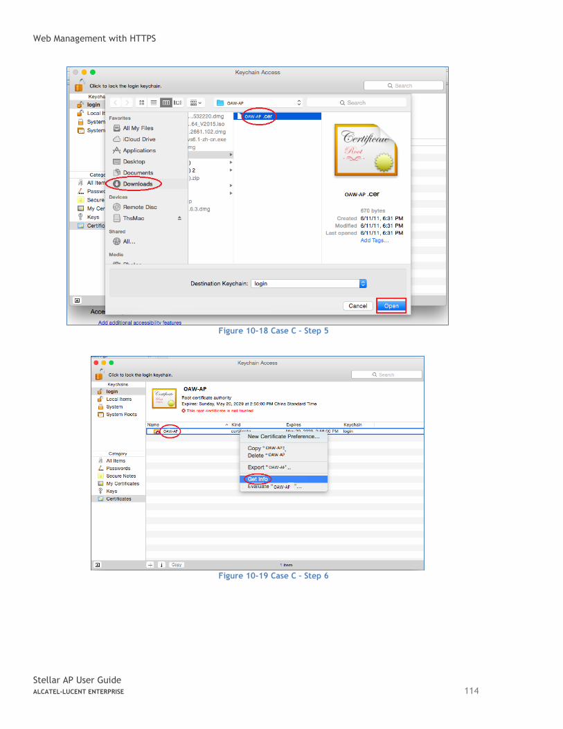
Web Management with HTTPS
Stellar AP User Guide ALCATEL-LUCENT ENTERPRISE 114
Figure 10-18 Case C – Step 5
Figure 10-19 Case C – Step 6
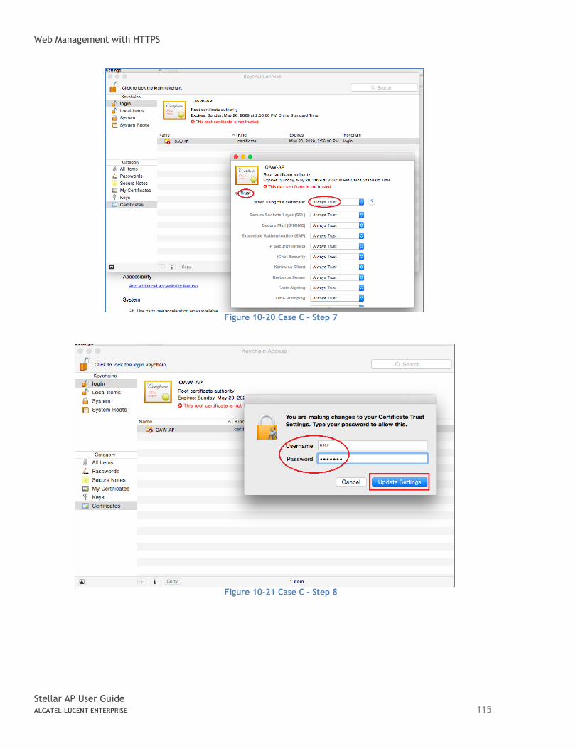
Web Management with HTTPS
Stellar AP User Guide ALCATEL-LUCENT ENTERPRISE 115
Figure 10-20 Case C – Step 7
Figure 10-21 Case C – Step 8
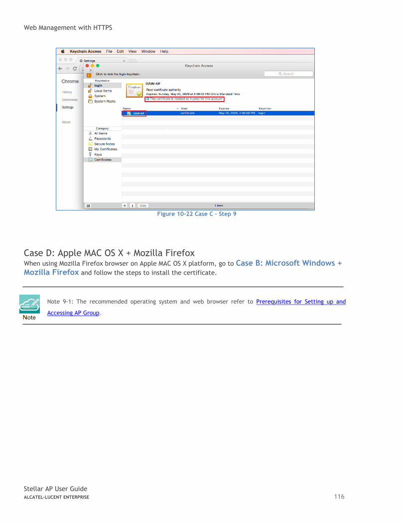
Web Management with HTTPS
Stellar AP User Guide ALCATEL-LUCENT ENTERPRISE 116
Figure 10-22 Case C – Step 9
Case D: Apple MAC OS X + Mozilla Firefox When using Mozilla Firefox browser on Apple MAC OS X platform, go to Case B: Microsoft Windows + Mozilla Firefox and follow the steps to install the certificate.
Note 9-1: The recommended operating system and web browser refer to Prerequisites for Setting up and
Accessing AP Group.
End-User Software License Agreement
Stellar AP User Guide ALCATEL-LUCENT ENTERPRISE 117
A. End-User Software License Agreement
ALCATEL-LUCENT ENTERPRISE USA, INC. ("ALU E") SOFTWARE LICENSE AGREEMENT IMPORTANT Please read the terms and conditions of this license agreement carefully before installing or downloading this software. The installation and use of the software is subject to these terms and conditions (Agreement). In this Agreement: "Licensee" or You, Your and Yourself, means: the legal person or entity that by its authorized agents or representatives installs and/or uses, the Software. "Software" (as defined in Section 1 below) for its own use and not for resale or distribution. "Licensor" means Alcatel-Lucent Enterprise USA, Inc. or one of its Affiliated Companies or authorized distributors entitled to distribute the Software. "Affiliated Companies" means any entity Controlling, Controlled by or under common Control, directly or indirectly, with Alcatel-Lucent Enterprise USA, Inc., "Control" means the ability to determine the management policies of a company or other entity through ownership of a majority of shares, by control of the board of management, by agreement or otherwise Provided that You accept the terms and conditions of this Software License Agreement (the "Agreement") in accordance with the following paragraph and pay all applicable "License Fees", the Software shall be licensed subject to, and the use of the Software shall be governed by, this Agreement, except to the extent that a separate valid license agreement has been previously entered into between Licensee and Licensor that sets forth the terms and conditions for the use and license of the Software for the number of users for which, and on the platform on which Licensee is installing it, on terms and conditions equivalent to this Agreement ("Separate Agreement"). Notwithstanding anything to the contrary herein, if Licensee has entered into a Separate Agreement, the Software is licensed subject to the terms and conditions of the Separate Agreement and the provisions of the Separate Agreement shall supersede and replace any and all conflicting terms and conditions of this Agreement, even if Licensee clicks the accept button below. In such case, for the avoidance of doubt, the Separate Agreement and this Agreement shall not be deemed two concurrent agreements, and only the Separate Agreement shall be deemed entered into between Licensee and ALU E with respect to the Software. IN THE EVENT WHERE NO SEPARATE AGREEMENT IS CURRENTLY IN FORCE, BY CLICKING THE ACCEPT BUTTON OR INSTALLING OR USING THE SOFTWARE, LICENSEE IS CONSENTING TO BE BOUND BY THE PROVISIONS OF THIS AGREEMENT AND IS BECOMING A PARTY TO THIS AGREEMENT. IF LICENSEE DOES NOT AGREE TO THE TERMS OF THIS AGREEMENT, CLICK THE BOX ADJACENT TO THE STATEMENT "I DO NOT ACCEPT THE LICENSE AGREEMENT" AND PROMPTLY DELETE ANY FILE CONTAINING THE SOFTWARE AND RETURN THE UNUSED SOFTWARE TO THE PARTY FROM WHOM YOU OBTAINED THE SOFTWARE. IF YOU HAVE ANY QUESTIONS ABOUT ANY PART OF THIS AGREEMENT PLEASE CONTACT YOUR ALE REPRESENTATIVE. LICENSEE IS ENCOURAGED TO SEEK LEGAL REVIEW OF THIS AGREEMENT PRIOR TO ACCEPTING IT. 1. License Grant and Restrictions of Use. This is a license, not a sales agreement, between the Licensee and ALU. Subject to Licensee paying all applicable fees, and subject to the terms set forth in this License Agreement ("Agreement''), ALU E or any of its Affiliated Companies, or, its local authorized Reseller or its authorized distributors from whom you purchased a license to use the software ("Licensor"), grants you this non- exclusive, non-transferable license to use the software program(s) delivered with this Agreement in
End-User Software License Agreement
Stellar AP User Guide ALCATEL-LUCENT ENTERPRISE 118
machine-readable form (the "Software"), and any documentation delivered with the Software (the "Documentation"). You shall not, and you shall not authorize other persons or entities to: (i) directly or indirectly, by electronic or other means, reproduce (except one copy for archival purposes), publish, distribute, rent, lease, sell, sublicense, assign or otherwise transfer the Software and Documentation or any part thereof or this Agreement; (ii) reverse-engineer, decompile, disassemble, merge, modify, use for competitive analysis, create derivative works of, or translate the Software or use any part of the Software outside the scope of the intended use of the Software; (iii) use the Software and Documentation for any purpose other than internal business purposes and not permit sublicensing, time sharing, rental, facility management, service bureau or application development use of the Software nor permit publication or distribution of results of any benchmark tests run on the Software without the express written permission of Licensor, or (iv) remove or obscure any copyright, trademark or other proprietary notices or legends from any portion of the Software, the Documentation or any associated documentation. This license solely enables you to install the Software on one or more server computers and to use the Software on that concurrent number and type of server computers for which you have paid Licensor the applicable license fees. The Software is considered to be in use when it resides in memory or is otherwise stored on a machine. The Software might not be usable by you until you have obtained a license key that enables the Software. By obtaining a license key for the Software, you ratify your assent to this Agreement. You agree to ensure that anyone who uses the Software or Documentation does so only for your authorized use and complies with the terms of this Agreement. You may not use the Software to provide time-sharing, service bureau or other similar types of services to third parties. If you use the Software within a country in the European Union, the Software Directive enacted by the Council of European Communities Directive dated 14 May, 1991, will apply to the examination of the Software to facilitate interoperability. You agree to notify Licensor of any such intended examination of the Software and may procure support and assistance from Licensor 2. Confidentiality. Licensor considers the Software to contain valuable trade secrets of ALU E, or it’s licensors, the unauthorized disclosure of which could cause irreparable harm to ALU E or it’s licensors. Except as expressly set forth herein, Licensee agrees to use reasonable efforts not to disclose the Software to any third party and not to use the Software other than for the purpose authorized by this License Agreement. This confidentiality obligation shall continue after any termination of this License Agreement. 3. Indemnity. Licensee agrees to indemnify, defend and hold Licensor harmless from any claim, lawsuit, legal proceeding, settlement or judgment (including without limitation Licensor's reasonable United States and local attorneys' and expert witnesses' fees and costs) arising out of or in connection with the unauthorized copying, marketing, performance or distribution of the Licensed Materials. 4. Limited Warranty. Unless a longer period is mandated by law, Licensor warrants that for a period of 90 days from the date of shipment of the media containing the Software to you, the Software, if operated as instructed, will perform substantially in accordance with the accompanying user documentation. Licensor's obligation under this warranty shall be limited as set forth below. Licensor does not warrant that the Software is totally free from error or omission or that its operation will be uninterrupted. All warranty obligations are void if the Software has been improperly installed or, except as allowed by applicable law, has been modified by a party other than Licensor. EXCEPT FOR THE WARRANTIES SET FORTH ABOVE, THE LICENSED MATERIALS ARE LICENSED "AS IS" AND LICENSOR AND ITS SUPPLIERS AND/OR AUTHORIZED REPRESENTATIVES DISCLAIM ANY AND ALL OTHER WARRANTIES, WHETHER EXPRESS OR IMPLIED, INCLUDING (WITHOUT LIMITATION) ANY IMPLIED WARRANTIES OF MERCHANTABILITY OR FITNESS FOR A PARTICULAR PURPOSE, TITLE AND NON-INFRINGEMENT, PROVISION OF OR FAILURE TO PROVIDE SUPPORT SERVICES, THAT SOFTWARE ERRORS (IF ANY) WILL BE CORRECTED, AND THAT THE SOFTWARE WILL OPERATE UNINTERRUPTED OR ERROR FREE. SOME STATES DO NOT ALLOW THE EXCLUSION OF IMPLIED WARRANTIES SO THE ABOVE EXCLUSIONS MAY NOT APPLY TO LICENSEE. THIS WARRANTY GIVES LICENSEE SPECIFIC LEGAL RIGHTS. LICENSEE MAY ALSO HAVE OTHER RIGHTS WHICH VARY FROM STATE TO STATE.
End-User Software License Agreement
Stellar AP User Guide ALCATEL-LUCENT ENTERPRISE 119
a. Specific Disclaimer for High Risk Activities: The Software are not designed or intended for use in high-risk activities, including, without limitation, nuclear facilities, aircraft navigation or aircraft communication systems, air traffic control, direct life support machines, or weapons systems, in which the failure of the Components could lead directly to death, personal injury, or severe physical or environmental damage ("High Risk Activities"). Licensor and its suppliers and/or authorized representatives specifically disclaim any express or implied warranty of fitness for High Risk Activities. 5. Limitation of Liability. Licensor's cumulative liability to Licensee or any other party for any loss or damages resulting from any claims, demands, or actions arising out of or relating to this License Agreement shall not exceed the license fee paid to LICENSOR for the Licensed Materials. IN NO EVENT SHALL LICENSOR AND ITS SUPPLIERS AND/OR AUTHORIZED REPRESENTATIVES BE LIABLE FOR ANY INDIRECT, INCIDENTAL, PUNITIVE, CONSEQUENTIAL, SPECIAL, OR EXEMPLARY DAMAGES, INCLUDING, WITHOUT LIMITATION, DAMAGES FOR INTERRUPTION OR COMPUTER FAILURE OR MALFUNCTION OR LOSS OF PROFITS OR REVENUES, GOODWILL, INFORMATION OR DATA, OR ANY OTHER PECUNIARY LOSS, WHATSOEVER, HOWEVER CAUSED AND ON ANY THEORY OF LIABILITY, WHETHER IN CONTRACT, STRICT LIABILITY, OR TORT (INCLUDING NEGLIGENCE OR OTHERWISE), ARISING IN ANY WAY OUT OF THE USE OR MISUSE OF THE LICENSED MATERIALS, OR THE PROVISION OF OR FAILURE TO PROVIDE SUPPORT SERVICES, EVEN IF LICENSOR HAS BEEN ADVISED OF THE POSSIBILITY OF SUCH DAMAGES. SOME JURISDICTIONS DO NOT ALLOW THE LIMITATION OR EXCLUSION OF LIABILITY FOR INCIDENTAL OR CONSEQUENTIAL DAMAGES, SO THE ABOVE LIMITATION OR EXCLUSION TO INCIDENTAL OR CONSEQUENTIAL DAMAGES MAY NOT APPLY TO LICENSEE. 6. Taxes and Duties. Licensee will be responsible to pay any sales, use, value added, consumption or goods and services tax, import duties, or any other taxes or charges which may be applicable to this product or license. 7. Export Control. This product is subject to the jurisdiction of the United States. Licensee may not export or re-export the Licensed Materials, without complying with all United States export laws and regulations, including but not limited to (i) obtaining prior authorization from the U.S. Department of Commerce if a validated export license is required, and (ii) obtaining "written assurances" from licensees, if required. 8. Support and Maintenance. Except as may be provided in a separate agreement between Licensor and Licensee, if any, Licensor is under no obligation to maintain or support the copies of the Licensed Materials made and distributed hereunder and Licensor has no obligation to furnish Licensee with any further assistance, documentation or information of any nature or kind. 9. Term. This License Agreement is effective upon Licensee installing or downloading the Software and shall continue until terminated. Licensee may terminate this License Agreement at any time by returning the Licensed Materials and all copies thereof and extracts therefrom to Licensor and certifying to Licensor in writing that all Licensed Materials and all copies thereof and extracts therefrom have been returned or erased by the memory of Licensee's computer or made non-readable. Licensor may terminate this License Agreement upon the breach by Licensee of any term hereof. Upon such termination by Licensor, Licensee agrees to return to Licensor or destroy the Licensed Materials and all copies and portions thereof. 10. Governing Law. This License Agreement shall be construed and governed in accordance with the laws of the State of California and controlling U.S. federal law. No choice of law rules of any jurisdiction will apply. 11. Severability. Should any term of this License Agreement be declared void or unenforceable by any court of competent jurisdiction, this Agreement will remain in effect with the term omitted, unless omission would frustrate the intent of the parties, in which case this Agreement will immediately terminate. 12. No Waiver. The failure of either party to enforce any rights granted hereunder or to take action against the other party in the event of any breach hereunder shall not be deemed a waiver by that party as to subsequent enforcement of rights or subsequent actions in the event of future breaches.
End-User Software License Agreement
Stellar AP User Guide ALCATEL-LUCENT ENTERPRISE 120
13. Notes to United States Government Users. Software and documentation are provided with restricted rights. Use, duplication or disclosure by the government is subject to (i) restrictions set forth in GSA ADP Schedule Contract with ALU's reseller or distributor.(s), or (ii) restrictions set forth in subparagraph (c) (1) and (2) of 48 CFR 52.227-19, as applicable. 14. Third Party Materials. Licensee is notified that the Software contains or may be accompanied by or packaged with third party software and materials licensed to Licensor by certain Suppliers and/or Authorized Representatives. Some Suppliers and/or Authorized Representatives are third party beneficiaries to this License Agreement with full rights of enforcement. Please refer to the file entitled "Third Party Licenses and Notices" in the user's documentation residing on the media for the Suppliers and/or Authorized Representatives license and notice terms. You agree to accept the license terms, including Warranty terms, of any and all such third party end user license agreements included in the Software or Documentation. 15. The Asset Management feature may be chosen during installation, it collects and stores information such as; the make, model and serial number of Licensee’s devices, the device software version numbers and system uptime information and such other information that would, in Licensors sole discretion, be utilized to improve the customer experience. The information helps us to diagnose potential problems, if any, in the software. We may or may not use the diagnostic information, in our sole discretion, to provide support solutions, including updates, upgrades or services packs, if any are made generally available. We will not use the Asset Management feature to track, collect or upload any data that personally identifies You (such as your name, address, email address) except Customer information provided to us by You. Licensee may opt-out of providing this data during installation of the Software by, as the case may be, checking or un-checking the box adjacent to the Asset Management feature option. If the box next to the Asset Management feature option is not checked the option will not be activated. If You decide to activate the Asset Management feature after full installation, You may do so by following the instructions on the Preference page for Asset Management in Your OmniVista 2500 client. Your use of the software constitutes your acknowledgment and agreement to the terms of use. 16. Entire Agreement. This Agreement is the complete and exclusive agreement between the parties with respect to the subject matter hereof, superseding and replacing any and all prior agreements, communications, and understandings (both written and oral) regarding such subject matter. This Agreement may only be modified, or any rights under it waived, by a written document executed by Officers of both parties. Any provisions of either purchase order, invoice, or similar document submitted by Licensee to Licensor, which are in addition to or inconsistent with the terms and conditions of this Agreement will be deemed stricken from such document. 17. Notices. If Licensee has any questions concerning this product or would like to otherwise contact ALU E, please write to: Alcatel-Lucent Enterprise USA, Inc., 26801 West Agoura Road, Calabasas, CA 91301 ATTN: Sales. Copyright 2020 Alcatel-Lucent Enterprise USA, Inc.