Embed Size (px)
Citation preview
OmegaGT XA MI 3360
Instruction manual Ver.1.5.7, Code no. 20 752 658
2
Distributor: Manufacturer: Metrel d.d. Ljubljanska cesta 77 SI-1354 Horjul E-mail: [email protected] http://www.metrel.si
Mark on your equipment certifies that it meets European Union requirements for EMC, LVD, ROHS regulations
© 2019 Metrel The trade names Metrel, Smartec, Eurotest, Autosequence are trademarks registered or pending in Europe and other countries No part of this publication may be reproduced or utilized in any form or by any means without permission in writing from METREL.
MI 3360 OmegaGT XA Table of contents
3
TABLE OF CONTENTS 1 General description ....................................................................................................... 7
1.1 Warnings and notes .................................................................................................... 7 1.1.1 Safety warnings ................................................................................................... 7 1.1.2 Warnings related to safety of measurement functions ......................................... 8
1.1.2.1 Flash HV ......................................................................................................... 8 1.1.2.2 Differential leak., Ipe leak., Touch leak., Ileak (W-PE), Primary leak., Power,
Leak’s & Power, Equipment leak., Applied part leak.__ ................................... 8 1.1.2.3 Insulation resistance ........................................................................................ 8
1.1.3 Markings on the instrument ................................................................................. 8 1.2 Power management .................................................................................................... 9
1.2.1 230 V / 110 V operation ....................................................................................... 9 1.2.2 Battery and charging, auto power off ................................................................... 9 1.2.3 Power Off, Restart ............................................................................................... 9
1.3 Standards applied ..................................................................................................... 10
2 Instrument set and accessories ................................................................................. 11
2.1 Standard set of the instrument .................................................................................. 11 2.2 Optional accessories ................................................................................................. 11
3 Instrument description................................................................................................ 12
3.1 Front panel ................................................................................................................ 12
4 Instrument operation .................................................................................................. 14
4.1 General meaning of keys .......................................................................................... 14 4.2 General meaning of touch gestures ........................................................................... 14 4.3 Virtual keyboard ........................................................................................................ 15 4.4 Safety checks ............................................................................................................ 15 4.5 Symbols and messages ............................................................................................ 16 4.6 Instrument main menu ............................................................................................... 20 4.7 General settings ........................................................................................................ 21
4.7.1 Language .......................................................................................................... 22 4.7.2 Date and time .................................................................................................... 22 4.7.3 Profiles .............................................................................................................. 22 4.7.4 Workspace Manager ......................................................................................... 22 4.7.5 Auto Sequence® groups.................................................................................... 22 4.7.6 Settings ............................................................................................................. 23 4.7.7 Initial Settings .................................................................................................... 24 4.7.8 About ................................................................................................................. 25 4.7.9 User Accounts ................................................................................................... 25
4.7.9.1 Signing in ...................................................................................................... 26 4.7.9.2 Changing user password, signing out ............................................................ 27 4.7.9.3 Managing accounts ....................................................................................... 28 4.7.9.4 Setting Black-box password .......................................................................... 29
4.8 Devices ..................................................................................................................... 30 4.9 Instrument profiles ..................................................................................................... 31 4.10 Workspace Manager ................................................................................................. 32
4.10.1 Workspaces and Exports ................................................................................... 32 4.10.2 Workspace Manager main menu ....................................................................... 32
4.10.2.1 Operations with Workspaces ......................................................................... 33 4.10.2.2 Operations with Exports ................................................................................ 34 4.10.2.3 Adding a new Workspace .............................................................................. 34
MI 3360 OmegaGT XA Table of contents
4
4.10.2.4 Opening a Workspace ................................................................................... 35 4.10.2.5 Deleting a Workspace / Export ...................................................................... 35 4.10.2.6 Importing a Workspace.................................................................................. 36 4.10.2.7 Exporting a Workspace ................................................................................. 37
4.11 Auto Sequence® groups ........................................................................................... 38 4.11.1 Auto Sequence® groups menu .......................................................................... 38
4.11.1.1 Operations in Auto Sequence® groups menu ................................................ 39 4.11.1.2 Selecting a list of Auto Sequences® .............................................................. 39 4.11.1.3 Deleting a list of Auto Sequences® ............................................................... 40
5 Memory Organizer ....................................................................................................... 41
5.1 Memory Organizer menu ........................................................................................... 41 5.1.1 Measurement statuses ...................................................................................... 41 5.1.2 Structure Objects ............................................................................................... 42
5.1.2.1 Measurement status indication under the Structure object ............................ 42 5.1.3 Selecting an active Workspace in Memory Organizer ........................................ 43 5.1.4 Adding Nodes in Memory Organizer .................................................................. 45 5.1.5 Operations in Tree Menu ................................................................................... 45
5.1.5.1 Operations on measurements (finished or empty measurements) ................. 45 5.1.5.2 Operations on Structure objects .................................................................... 47 5.1.5.3 View / Edit parameters and attachments of a Structure object ....................... 48 5.1.5.4 Add a new Structure Object ........................................................................... 50 5.1.5.5 Add a new measurement ............................................................................... 51 5.1.5.6 Clone a Structure object ................................................................................ 53 5.1.5.7 Clone a measurement ................................................................................... 54 5.1.5.8 Copy & Paste a Structure object .................................................................... 54 5.1.5.9 Copy & Paste a measurement ....................................................................... 56 5.1.5.10 Cut & Paste a Structure object with sub-items ............................................... 56 5.1.5.11 Delete a Structure object ............................................................................... 57 5.1.5.12 Delete a measurement .................................................................................. 58 5.1.5.13 Rename a Structure object ............................................................................ 59 5.1.5.14 Recall and Retest selected measurement ..................................................... 59
5.1.6 Searching in Memory Organizer ........................................................................ 61
6 Single tests .................................................................................................................. 64
6.1 Selection modes ........................................................................................................ 64 6.1.1 Single test screens ............................................................................................ 65
6.1.1.1 Single test start screen .................................................................................. 66 6.1.1.2 Setting parameters and limits of single tests .................................................. 67 6.1.1.3 Single test screen during test ........................................................................ 68 6.1.1.4 Single test result screen ................................................................................ 69 6.1.1.5 Single test memory screen ............................................................................ 70
6.1.2 Single test (inspection) screens ......................................................................... 71 6.1.2.1 Single test (inspection) start screen ............................................................... 71 6.1.2.2 Single test (Inspection) screen during test ..................................................... 72 6.1.2.3 Single test (Inspection) result screen ............................................................. 73 6.1.2.4 Single test (inspection) memory screen ......................................................... 74
6.1.3 Help screens ..................................................................................................... 75 6.2 Single test measurements ......................................................................................... 76
6.2.1 Visual inspection................................................................................................ 76 6.2.2 Continuity // Protective earth resistance ............................................................. 77
6.2.2.1 Compensation of test lead / IEC test cable resistance ................................... 79 6.2.2.2 Limit Calculator ............................................................................................. 80
6.2.3 Flash test ........................................................................................................... 82 6.2.4 Insulation resistance (Riso, Riso-S) ................................................................... 83
MI 3360 OmegaGT XA Table of contents
5
6.2.5 Sub-leakage (Isub, Isub-S) ................................................................................ 85 6.2.6 Differential Leakage ........................................................................................... 87 6.2.7 Ipe Leakage ....................................................................................................... 88 6.2.8 Touch Leakage .................................................................................................. 89 6.2.9 Power ................................................................................................................ 91 6.2.10 Leak's & Power .................................................................................................. 92 6.2.11 PRCD test ......................................................................................................... 93 6.2.12 RCD test ............................................................................................................ 95 6.2.13 PE conductor (PRCD) ....................................................................................... 97 6.2.14 Open conductor (PRCD) .................................................................................... 98 6.2.15 PRCD PE probe test ........................................................................................ 100 6.2.16 Polarity ............................................................................................................ 102 6.2.17 Clamp current .................................................................................................. 104 6.2.18 Insulation resistance – Riso (welding equipment) ............................................ 105 6.2.19 Welding Circuit Leakage – I leak (W-PE) ......................................................... 106 6.2.20 Primary Leakage ............................................................................................. 108 6.2.21 No-load voltage ............................................................................................... 109 6.2.22 Insulation resistance – Riso (medical equipment) ............................................ 111 6.2.23 Equipment Leakage (medical equipment) ........................................................ 113 6.2.24 Applied Part Leakage (medical equipment) ..................................................... 115 6.2.25 Touch Current (medical equipment)................................................................. 117 6.2.26 Functional test ................................................................................................. 119
7 Auto Sequences® ..................................................................................................... 120
7.1 Selection of Auto Sequences® ................................................................................ 120 7.1.1 Selecting an active Auto Sequence® group in Auto Sequences® menu .......... 120 7.1.2 Searching in Auto Sequences® menu ............................................................. 121 7.1.3 Organization of Auto Sequences® in Auto Sequences® menu ........................ 123
7.2 Organization of an Auto Sequence® ....................................................................... 124 7.2.1 Auto Sequence® view menu ........................................................................... 124
7.2.1.1 Auto Sequence® view menu (Header is selected) ....................................... 124 7.2.1.2 Auto Sequence® view menu (measurement is selected) ............................. 125 7.2.1.3 Auto Sequence® Configurator menu ........................................................... 126 7.2.1.4 Indication of Loops ...................................................................................... 127 7.2.1.5 Managing multiple points ............................................................................. 127
7.2.2 Step by step execution of Auto Sequences® ................................................... 127 7.2.3 Auto Sequence® result screen ........................................................................ 129 7.2.4 Auto Sequence® memory screen .................................................................... 131 7.2.5 Print label menu............................................................................................... 132
8 Maintenance .............................................................................................................. 133
8.1 Periodic calibration .................................................................................................. 133 8.2 Fuses ...................................................................................................................... 133 8.3 Service .................................................................................................................... 133 8.4 Cleaning .................................................................................................................. 133
9 Communications ....................................................................................................... 134
9.1 USB and RS232 communication with PC ................................................................ 134 9.2 Bluetooth communication ........................................................................................ 134 9.3 Bluetooth communication with printers and scanners .............................................. 135 9.4 RS232 communication with other external devices ................................................. 135 9.5 Connections to test adapters ................................................................................... 135
9.5.1 Active 3 Phase Adapter /Plus (A 1322 / A 1422) .............................................. 135 9.5.2 110 V Test Adapter (A 1474) ........................................................................... 136
10 Technical specifications ........................................................................................... 137
MI 3360 OmegaGT XA Table of contents
6
10.1 Continuity // Protective earth resistance .................................................................. 137 10.2 Insulation Resistance (Riso, Riso-S) ....................................................................... 137 10.3 Sub-Leakage Current, Substitute Leakage Current - S ............................................ 138 10.4 Differential Leakage current .................................................................................... 138 10.5 PE leakage current .................................................................................................. 138 10.6 Touch leakage current ............................................................................................. 139 10.7 Power ...................................................................................................................... 139 10.8 Leak’s & Power ....................................................................................................... 140 10.9 PRCD test ............................................................................................................... 142 10.10 RCD test ................................................................................................................. 142 10.11 PE conductor (PRCD) ............................................................................................. 143 10.12 Open conductor (PRCD) ......................................................................................... 143 10.13 PRCD PE probe test ............................................................................................... 143 10.14 Polarity .................................................................................................................... 144 10.15 Clamp current.......................................................................................................... 144 10.16 Flash test ................................................................................................................ 144 10.17 Insulation resistance Riso (welding equipment) ....................................................... 145 10.18 Welding Circuit leakage (Ileak W-PE) ...................................................................... 145 10.19 Primary Leakage (I diff) ........................................................................................... 145 10.20 No-load voltage ....................................................................................................... 145 10.21 Insulation Resistance (medical equipment) ............................................................. 146 10.22 Equipment leakage ................................................................................................. 146 10.23 Applied Part leakage ............................................................................................... 147 10.24 Touch current (medical equipment) ......................................................................... 147 10.25 General data ........................................................................................................... 148
Appendix A Structure objects in OmegaGT XA .......................................................... 149
Appendix B Profile Notes .............................................................................................. 150
Appendix C Print labels and write / read RFID / NFC tags ........................................... 151
C.1 PAT tag format ........................................................................................................ 151 C.2 Generic tag format .................................................................................................. 153
Appendix D Default list of Auto Sequences® ............................................................... 155
Appendix E Programming of Auto Sequences® on Metrel ES Manager ........................ 156
E.1 Auto Sequence® Editor workspace ......................................................................... 156 E.2 Managing groups of Auto Sequences® ................................................................... 157
E.2.1 Auto Sequence® Name, Description and Image editing .................................. 159 E.2.2 Search within selected Auto Sequence® group ............................................... 160
E.3 Elements of an Auto Sequence® ............................................................................ 161 E.3.1 Auto Sequence® steps .................................................................................... 161 E.3.2 Single tests ...................................................................................................... 161 E.3.3 Flow commands .............................................................................................. 161 E.3.4 Number of measurement steps ........................................................................ 161
E.4 Creating / modifying an Auto Sequence® ................................................................ 161 E.5 Description of flow commands ................................................................................. 162 E.6 Custom Inspections programming ........................................................................... 165
E.6.1 Creating and editing Custom Inspections ........................................................ 165 E.6.2 Applying Custom Inspections........................................................................... 167
Appendix F Testing 110 V appliances .............................................................................. 168
MI 3360 OmegaGT XA General description
7
1 General description
1.1 Warnings and notes
Read before use
1.1.1 Safety warnings
In order to reach high level of operator safety while carrying out various measurements using the OmegaGT XA instrument, as well as to keep the test equipment undamaged, it is necessary to consider the following general warnings:
Read this user manual carefully, otherwise use of the instrument may be dangerous for the operator, for the instrument or for the equipment under test!
Consider warning markings on the instrument!
If the test equipment is used in manner not specified in this user manual the protection provided by the equipment may be impaired!
Do not use the instrument and accessories if any damage is noticed!
Regularly check the instrument and accessories for correct functioning to avoid hazard that could occur from misleading results.
Consider all generally known precautions in order to avoid risk of electric shock while dealing with hazardous voltages!
Use only standard or optional test accessories supplied by your distributor!
Only test equipment provided or approved by Metrel should be connected to 3-PHASE ADAPTER connector.
Do not connect external voltage to CLAMP inputs. It is intended only for connection of Clamps approved by Metrel.
Use only earthed mains outlets to supply the instrument!
If working on other than 230 V TN/TT voltage systems refer to chapter 1.2.1 230 V / 110 V operation.
In case a fuse has blown refer to chapter 8.2 Fuses to replace it!
Instrument servicing and calibration is allowed to be carried out only by a competent authorized person!
LCD screenshots in this document are informative only. Screens on the instrument may be slightly different.
Metrel Auto Sequences® are designed as guidance to tests in order to significantly reduce testing time, improve work scope and increase traceability of
MI 3360 OmegaGT XA General description
8
the tests performed. METREL assumes no responsibility for any Auto Sequence® by any means. It is the user’s responsibility, to check adequacy for the purpose of use of the selected Auto Sequence®. This includes type and number of tests, sequence flow, test parameters and limits.
1.1.2 Warnings related to safety of measurement functions
1.1.2.1 Flash HV
A voltage of up to 3 kVAC between FLASH and mains socket LN terminals / 1.5 kVAC
between main socket’s LN and PE socket terminals / 1.5 kVAC between FLASH and mains socket PE terminal is applied to the instrument’s outputs during the test. Although the current of the HV source is limited to safe level special safety consideration must be taken when performing this test!
1.1.2.2 Differential leak., Ipe leak., Touch leak., Ileak (W-PE), Primary leak., Power, Leak’s & Power, Equipment leak., Applied part leak.__
Load currents higher than 10 A can result in high temperatures of fuse holders! It is
advisable not to run tested devices with load currents above 10 A for more than 15 minutes. Recovery period for cooling is required before proceeding with tests! Maximum intermittent duty cycle for measurements with load currents higher than 10 A is 50 %.
1.1.2.3 Insulation resistance
Do not touch the test object during the measurement or before it is fully discharged! Risk of electric shock!
1.1.3 Markings on the instrument
Read the Instruction manual with special care to safety operation«. The symbol requires an action!
Dangerous high voltage is present on terminals during the test. Consider all precautions in order to avoid risk of electric shock.
Mark on your equipment certifies that it meets European Union requirements for EMC, LVD, and ROHS regulations.
This equipment should be recycled as electronic waste.
MI 3360 OmegaGT XA General description
9
1.2 Power management
1.2.1 230 V / 110 V operation
The instrument works on 110 V and 230 V mains. 110 V and 230 V appliances can be fully tested, except if testing 110 V appliances in IT or CT supply system; see Appendix F for limitations. In UK and Aus/Nz models only 110 V mains voltage will be applied to the mains test socket if the 110 V test adapter (A 1474) is connected to the instrument.
1.2.2 Battery and charging, auto power off
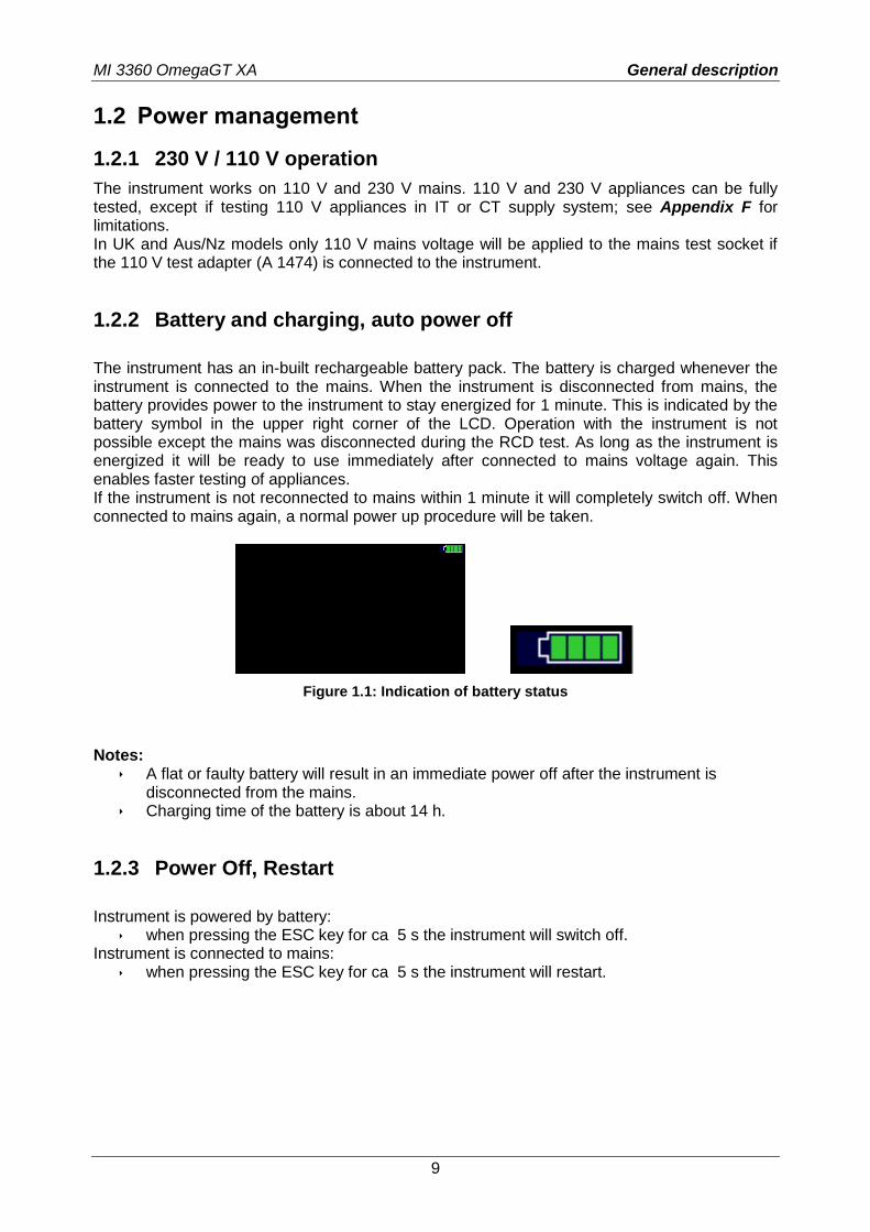
The instrument has an in-built rechargeable battery pack. The battery is charged whenever the instrument is connected to the mains. When the instrument is disconnected from mains, the battery provides power to the instrument to stay energized for 1 minute. This is indicated by the battery symbol in the upper right corner of the LCD. Operation with the instrument is not possible except the mains was disconnected during the RCD test. As long as the instrument is energized it will be ready to use immediately after connected to mains voltage again. This enables faster testing of appliances. If the instrument is not reconnected to mains within 1 minute it will completely switch off. When connected to mains again, a normal power up procedure will be taken.
Figure 1.1: Indication of battery status
Notes:
A flat or faulty battery will result in an immediate power off after the instrument is disconnected from the mains.
Charging time of the battery is about 14 h.
1.2.3 Power Off, Restart
Instrument is powered by battery:
when pressing the ESC key for ca 5 s the instrument will switch off. Instrument is connected to mains:
when pressing the ESC key for ca 5 s the instrument will restart.
MI 3360 OmegaGT XA General description
10
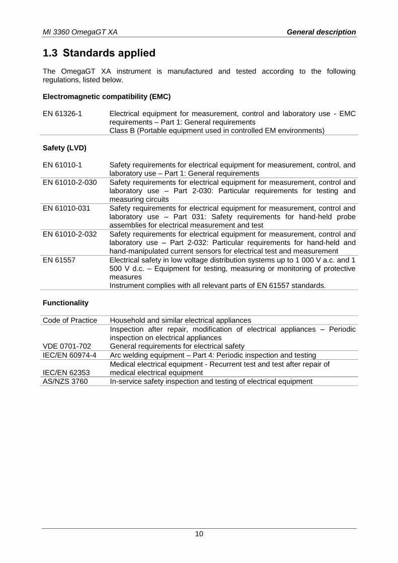
1.3 Standards applied
The OmegaGT XA instrument is manufactured and tested according to the following regulations, listed below. Electromagnetic compatibility (EMC) EN 61326-1 Electrical equipment for measurement, control and laboratory use - EMC
requirements – Part 1: General requirements Class B (Portable equipment used in controlled EM environments)
Safety (LVD) EN 61010-1 Safety requirements for electrical equipment for measurement, control, and
laboratory use – Part 1: General requirements
EN 61010-2-030 Safety requirements for electrical equipment for measurement, control and laboratory use – Part 2-030: Particular requirements for testing and measuring circuits
EN 61010-031 Safety requirements for electrical equipment for measurement, control and laboratory use – Part 031: Safety requirements for hand-held probe assemblies for electrical measurement and test
EN 61010-2-032 Safety requirements for electrical equipment for measurement, control and laboratory use – Part 2-032: Particular requirements for hand-held and hand-manipulated current sensors for electrical test and measurement
EN 61557
Electrical safety in low voltage distribution systems up to 1 000 V a.c. and 1 500 V d.c. – Equipment for testing, measuring or monitoring of protective measures Instrument complies with all relevant parts of EN 61557 standards.
Functionality
Code of Practice Household and similar electrical appliances
VDE 0701-702
Inspection after repair, modification of electrical appliances – Periodic inspection on electrical appliances General requirements for electrical safety
IEC/EN 60974-4 Arc welding equipment – Part 4: Periodic inspection and testing
IEC/EN 62353 Medical electrical equipment - Recurrent test and test after repair of medical electrical equipment
AS/NZS 3760 In-service safety inspection and testing of electrical equipment
MI 3360 OmegaGT XA Instrument set and accessories
11
2 Instrument set and accessories
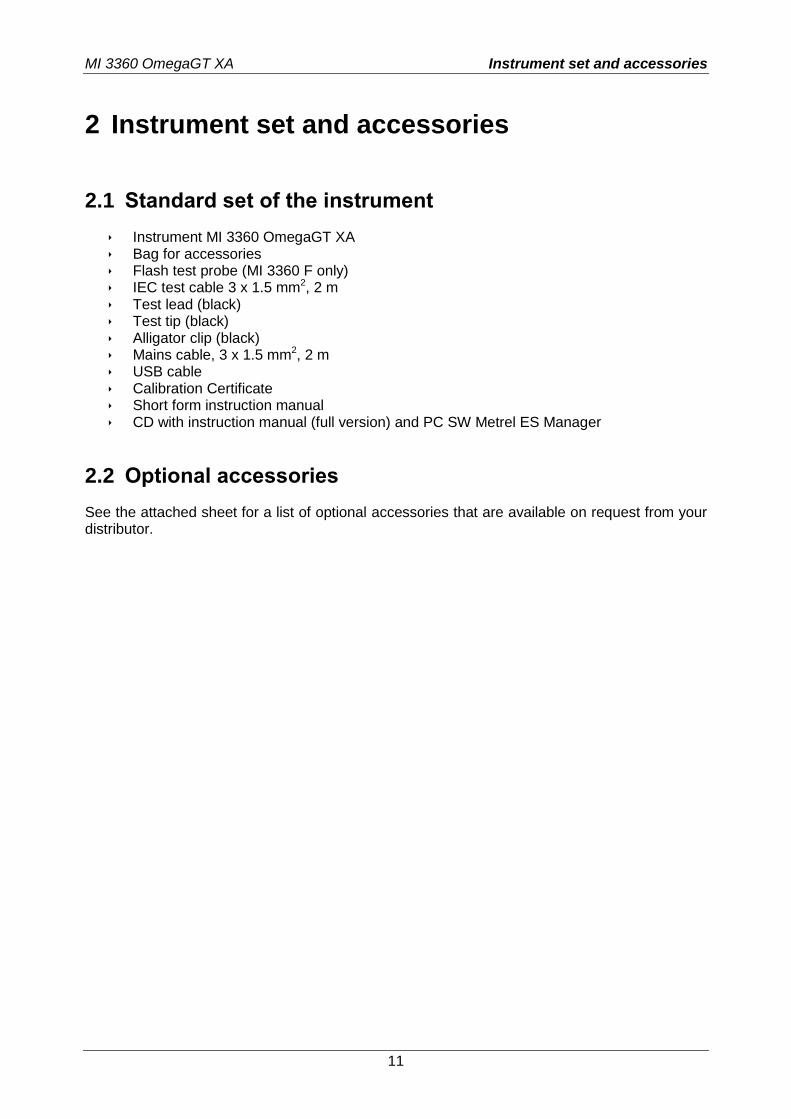
2.1 Standard set of the instrument
Instrument MI 3360 OmegaGT XA Bag for accessories Flash test probe (MI 3360 F only) IEC test cable 3 x 1.5 mm2, 2 m Test lead (black) Test tip (black) Alligator clip (black) Mains cable, 3 x 1.5 mm2, 2 m USB cable Calibration Certificate Short form instruction manual CD with instruction manual (full version) and PC SW Metrel ES Manager
2.2 Optional accessories
See the attached sheet for a list of optional accessories that are available on request from your distributor.
MI 3360 OmegaGT XA Instrument description
12
3 Instrument description
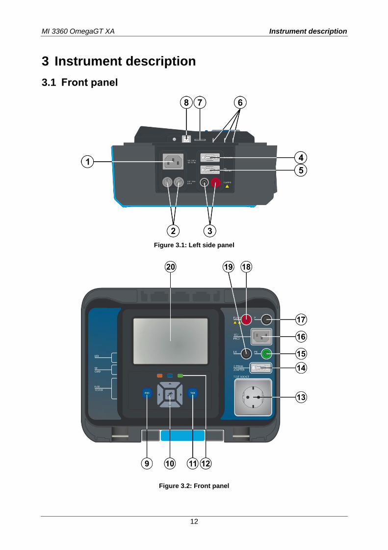
3.1 Front panel
Figure 3.1: Left side panel
Figure 3.2: Front panel
MI 3360 OmegaGT XA Instrument description
13
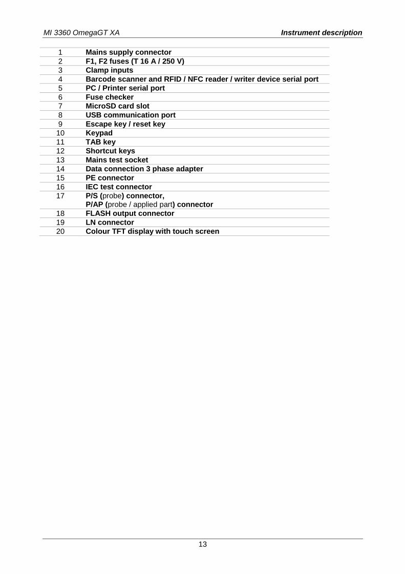
1 Mains supply connector
2 F1, F2 fuses (T 16 A / 250 V)
3 Clamp inputs
4 Barcode scanner and RFID / NFC reader / writer device serial port
5 PC / Printer serial port
6 Fuse checker
7 MicroSD card slot
8 USB communication port
9 Escape key / reset key
10 Keypad
11 TAB key
12 Shortcut keys
13 Mains test socket
14 Data connection 3 phase adapter
15 PE connector
16 IEC test connector
17 P/S (probe) connector, P/AP (probe / applied part) connector
18 FLASH output connector
19 LN connector
20 Colour TFT display with touch screen
MI 3360 OmegaGT XA Instrument operation
14
4 Instrument operation
The instrument can be manipulated via a keypad or touch screen.
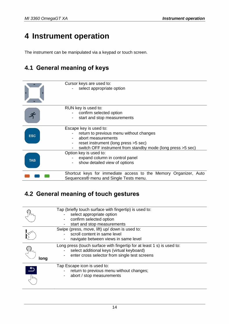
4.1 General meaning of keys
Cursor keys are used to: - select appropriate option
RUN key is used to: - confirm selected option - start and stop measurements
Escape key is used to: - return to previous menu without changes - abort measurements - reset instrument (long press >5 sec) - switch OFF instrument from standby mode (long press >5 sec)
Option key is used to: - expand column in control panel - show detailed view of options
Shortcut keys for immediate access to the Memory Organizer, Auto Sequences® menu and Single Tests menu.
4.2 General meaning of touch gestures
Tap (briefly touch surface with fingertip) is used to: - select appropriate option - confirm selected option - start and stop measurements
Swipe (press, move, lift) up/ down is used to: - scroll content in same level - navigate between views in same level
long
Long press (touch surface with fingertip for at least 1 s) is used to: - select additional keys (virtual keyboard) - enter cross selector from single test screens
Tap Escape icon is used to: - return to previous menu without changes; - abort / stop measurements
MI 3360 OmegaGT XA Instrument operation
15
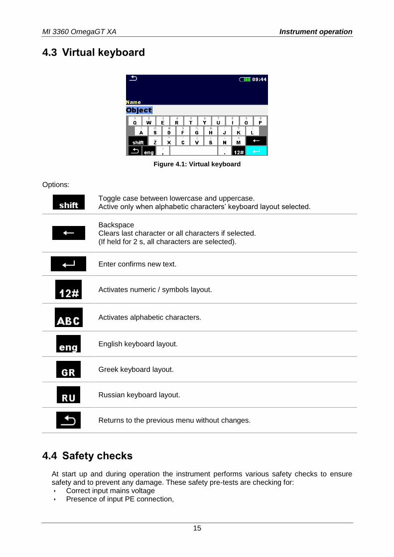
4.3 Virtual keyboard
Figure 4.1: Virtual keyboard
Options:
Toggle case between lowercase and uppercase. Active only when alphabetic characters’ keyboard layout selected.
Backspace Clears last character or all characters if selected. (If held for 2 s, all characters are selected).
Enter confirms new text.
Activates numeric / symbols layout.
Activates alphabetic characters.
English keyboard layout.
Greek keyboard layout.
Russian keyboard layout.
Returns to the previous menu without changes.
4.4 Safety checks
At start up and during operation the instrument performs various safety checks to ensure safety and to prevent any damage. These safety pre-tests are checking for: Correct input mains voltage Presence of input PE connection,
MI 3360 OmegaGT XA Instrument operation
16
Any external voltage against earth on mains test socket Excessive leakage currents through measuring I/O’s, Too low resistance between L and N of tested device, Proper operation of safety relevant internal electronic circuits
If a safety check fails, an appropriate warning message will be displayed and safety measures will be taken. The warnings and safety measures are described in chapter 4.5 Symbols and messages.
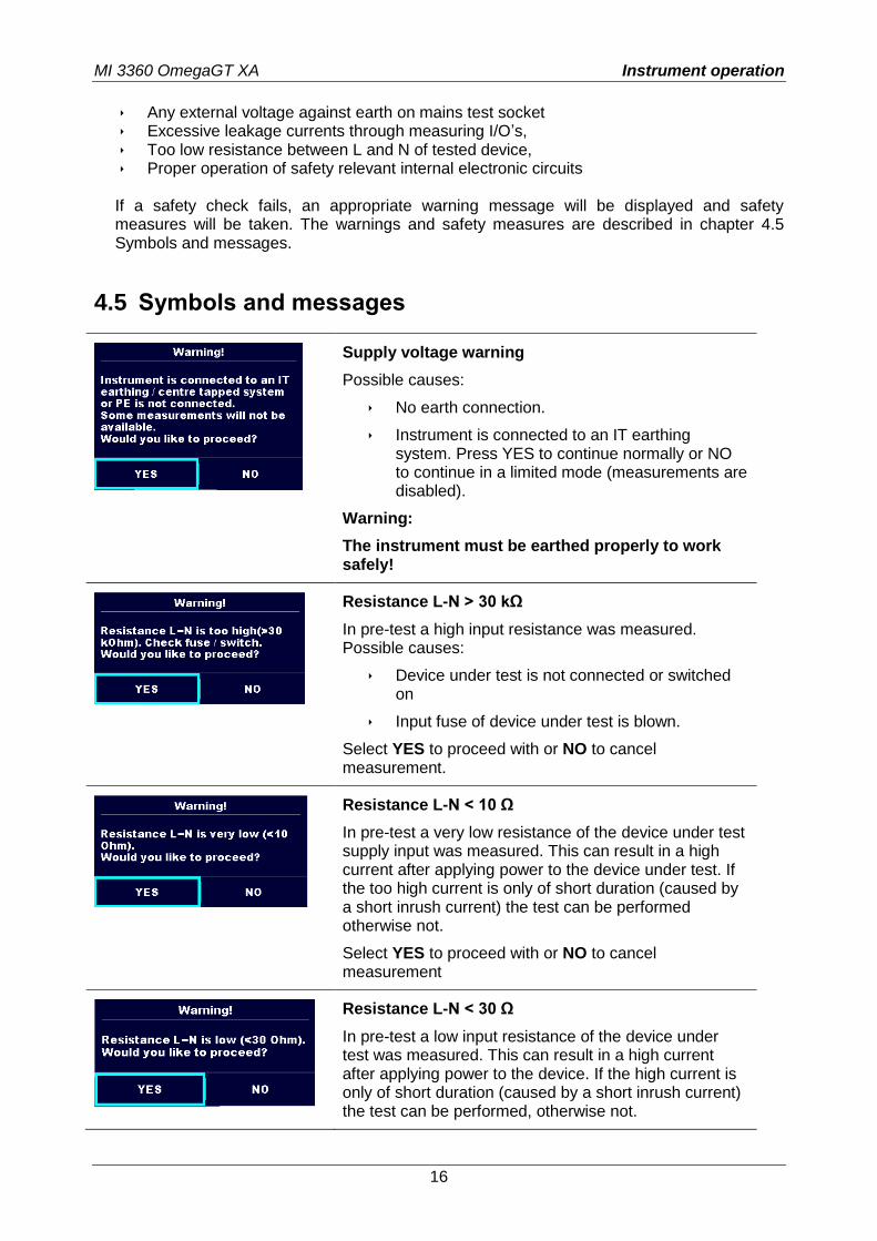
4.5 Symbols and messages
Supply voltage warning
Possible causes:
No earth connection.
Instrument is connected to an IT earthing system. Press YES to continue normally or NO to continue in a limited mode (measurements are disabled).
Warning:
The instrument must be earthed properly to work safely!
Resistance L-N > 30 kΩ
In pre-test a high input resistance was measured. Possible causes:
Device under test is not connected or switched on
Input fuse of device under test is blown.
Select YES to proceed with or NO to cancel measurement.
Resistance L-N < 10 Ω
In pre-test a very low resistance of the device under test supply input was measured. This can result in a high current after applying power to the device under test. If the too high current is only of short duration (caused by a short inrush current) the test can be performed otherwise not.
Select YES to proceed with or NO to cancel measurement
Resistance L-N < 30 Ω
In pre-test a low input resistance of the device under test was measured. This can result in a high current after applying power to the device. If the high current is only of short duration (caused by a short inrush current) the test can be performed, otherwise not.
MI 3360 OmegaGT XA Instrument operation
17
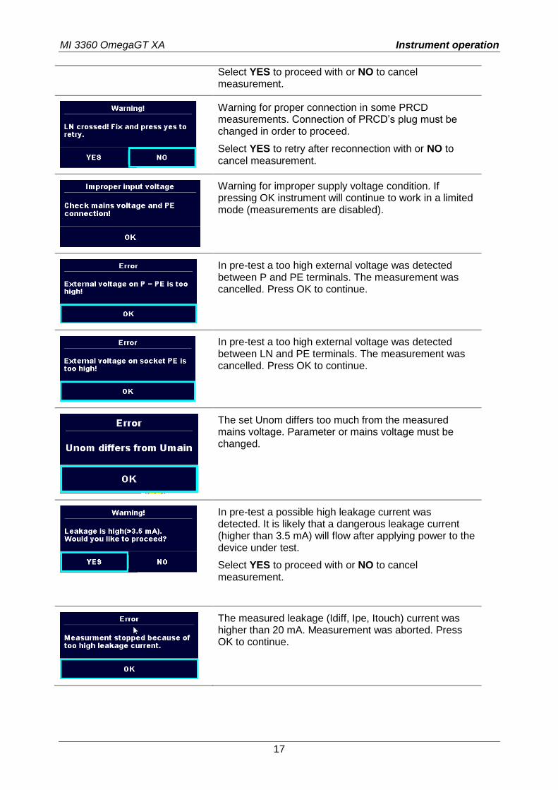
Select YES to proceed with or NO to cancel measurement.
Warning for proper connection in some PRCD measurements. Connection of PRCD’s plug must be changed in order to proceed.
Select YES to retry after reconnection with or NO to cancel measurement.
Warning for improper supply voltage condition. If pressing OK instrument will continue to work in a limited mode (measurements are disabled).
In pre-test a too high external voltage was detected between P and PE terminals. The measurement was cancelled. Press OK to continue.
In pre-test a too high external voltage was detected between LN and PE terminals. The measurement was cancelled. Press OK to continue.
The set Unom differs too much from the measured mains voltage. Parameter or mains voltage must be changed.
In pre-test a possible high leakage current was detected. It is likely that a dangerous leakage current (higher than 3.5 mA) will flow after applying power to the device under test.
Select YES to proceed with or NO to cancel measurement.
The measured leakage (Idiff, Ipe, Itouch) current was higher than 20 mA. Measurement was aborted. Press OK to continue.
MI 3360 OmegaGT XA Instrument operation
18
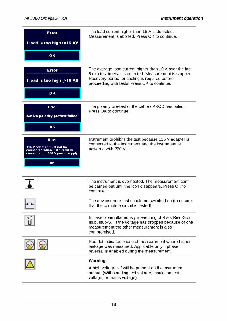
The load current higher than 16 A is detected. Measurement is aborted. Press OK to continue.
The average load current higher than 10 A over the last 5 min test interval is detected. Measurement is stopped. Recovery period for cooling is required before proceeding with tests! Press OK to continue.
The polarity pre-test of the cable / PRCD has failed. Press OK to continue.
Instrument prohibits the test because 115 V adapter is connected to the instrument and the instrument is powered with 230 V.
The instrument is overheated. The measurement can’t be carried out until the icon disappears. Press OK to continue.
The device under test should be switched on (to ensure that the complete circuit is tested).
In case of simultaneously measuring of Riso, Riso-S or Isub, Isub-S. If the voltage has dropped because of one measurement the other measurement is also compromised.
Red dot indicates phase of measurement where higher leakage was measured. Applicable only if phase reversal is enabled during the measurement.
Warning!
A high voltage is / will be present on the instrument output! (Withstanding test voltage, Insulation test voltage, or mains voltage).
MI 3360 OmegaGT XA Instrument operation
19
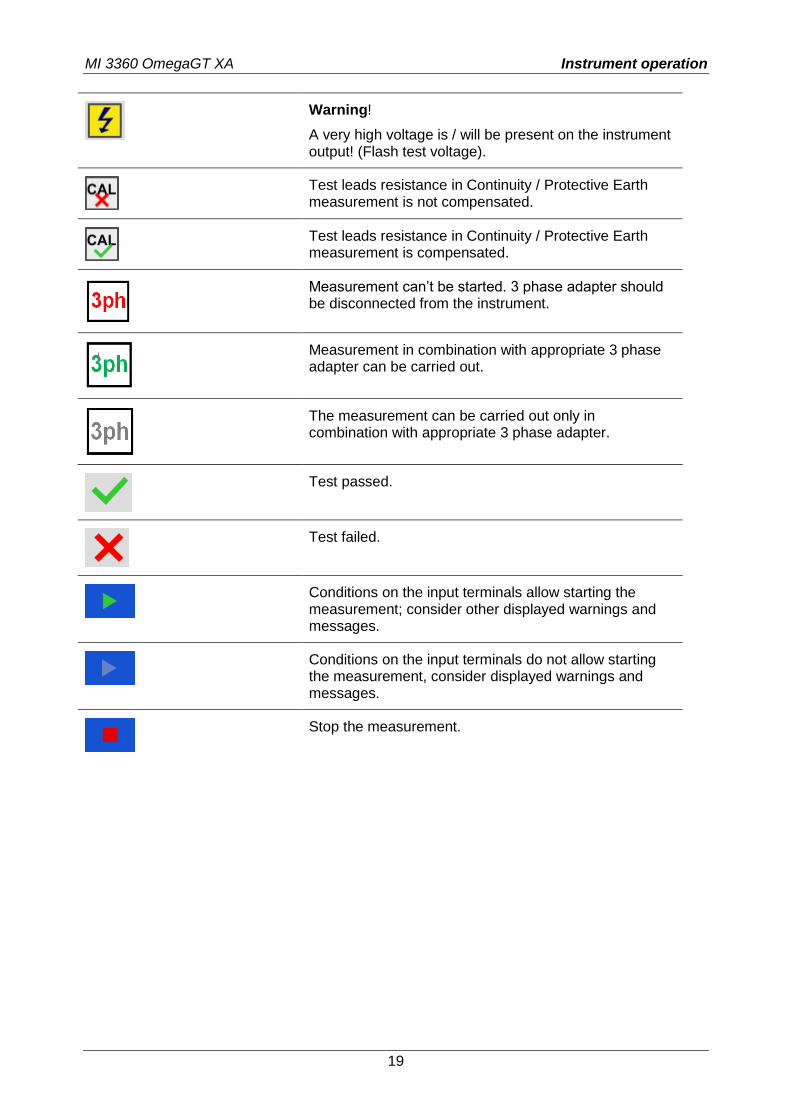
Warning!
A very high voltage is / will be present on the instrument output! (Flash test voltage).
Test leads resistance in Continuity / Protective Earth measurement is not compensated.
Test leads resistance in Continuity / Protective Earth measurement is compensated.
Measurement can’t be started. 3 phase adapter should be disconnected from the instrument.
Measurement in combination with appropriate 3 phase adapter can be carried out.
The measurement can be carried out only in combination with appropriate 3 phase adapter.
Test passed.
Test failed.
Conditions on the input terminals allow starting the measurement; consider other displayed warnings and messages.
Conditions on the input terminals do not allow starting the measurement, consider displayed warnings and messages.
Stop the measurement.
MI 3360 OmegaGT XA Instrument operation
20
4.6 Instrument main menu
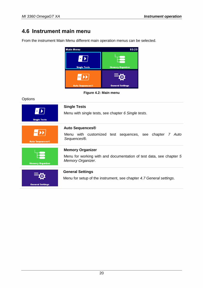
From the instrument Main Menu different main operation menus can be selected.
Figure 4.2: Main menu
Options
Single Tests
Menu with single tests, see chapter 6 Single tests.
Auto Sequences®
Menu with customized test sequences, see chapter 7 Auto Sequences®.
Memory Organizer
Menu for working with and documentation of test data, see chapter 5 Memory Organizer.
General Settings
Menu for setup of the instrument, see chapter 4.7 General settings.
MI 3360 OmegaGT XA Instrument operation
21
4.7 General settings
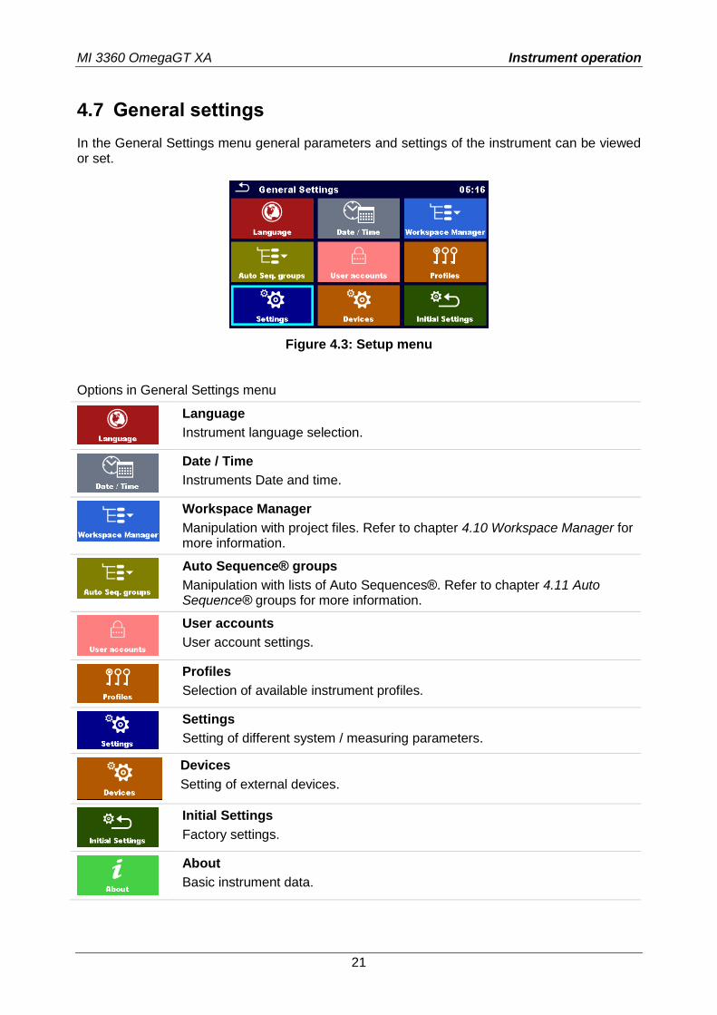
In the General Settings menu general parameters and settings of the instrument can be viewed or set.
Figure 4.3: Setup menu
Options in General Settings menu
Language
Instrument language selection.
Date / Time
Instruments Date and time.
Workspace Manager
Manipulation with project files. Refer to chapter 4.10 Workspace Manager for more information.
Auto Sequence® groups
Manipulation with lists of Auto Sequences®. Refer to chapter 4.11 Auto Sequence® groups for more information.
User accounts
User account settings.
Profiles
Selection of available instrument profiles.
Settings
Setting of different system / measuring parameters.
Devices
Setting of external devices.
Initial Settings
Factory settings.
About
Basic instrument data.
MI 3360 OmegaGT XA Instrument operation
22
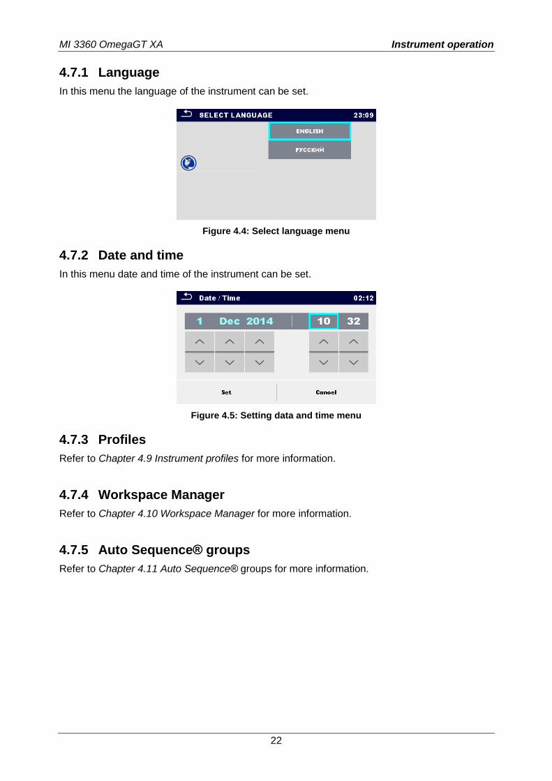
4.7.1 Language
In this menu the language of the instrument can be set.
Figure 4.4: Select language menu
4.7.2 Date and time
In this menu date and time of the instrument can be set.
Figure 4.5: Setting data and time menu
4.7.3 Profiles
Refer to Chapter 4.9 Instrument profiles for more information.
4.7.4 Workspace Manager
Refer to Chapter 4.10 Workspace Manager for more information.
4.7.5 Auto Sequence® groups
Refer to Chapter 4.11 Auto Sequence® groups for more information.
MI 3360 OmegaGT XA Instrument operation
23
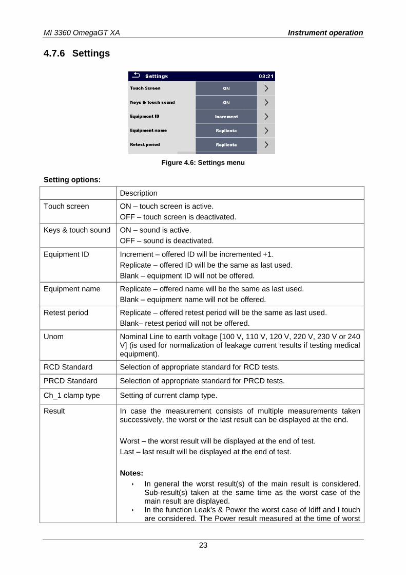
4.7.6 Settings
Figure 4.6: Settings menu
Setting options:
Description
Touch screen ON – touch screen is active.
OFF – touch screen is deactivated.
Keys & touch sound ON – sound is active.
OFF – sound is deactivated.
Equipment ID
Increment – offered ID will be incremented +1.
Replicate – offered ID will be the same as last used.
Blank – equipment ID will not be offered.
Equipment name Replicate – offered name will be the same as last used.
Blank – equipment name will not be offered.
Retest period Replicate – offered retest period will be the same as last used.
Blank– retest period will not be offered.
Unom Nominal Line to earth voltage [100 V, 110 V, 120 V, 220 V, 230 V or 240 V] (is used for normalization of leakage current results if testing medical equipment).
RCD Standard Selection of appropriate standard for RCD tests.
PRCD Standard Selection of appropriate standard for PRCD tests.
Ch_1 clamp type Setting of current clamp type.
Result In case the measurement consists of multiple measurements taken successively, the worst or the last result can be displayed at the end.
Worst – the worst result will be displayed at the end of test.
Last – last result will be displayed at the end of test.
Notes:
In general the worst result(s) of the main result is considered. Sub-result(s) taken at the same time as the worst case of the main result are displayed.
In the function Leak's & Power the worst case of Idiff and I touch are considered. The Power result measured at the time of worst
MI 3360 OmegaGT XA Instrument operation
24
Idiff is displayed. In the function Riso, Riso-S the worst case of Riso and Riso-S
are considered. The Um result measured at the time of worst Riso is displayed.
For the Power measurement the last result is considered regardless of the Result setting.
Test mode Standard – Visual and Functional inspection status fields should be set manually.
Expert – All Visual and Functional inspection status fields are filled automatically with PASS status.
Auto seq. flow Ends if fail – Auto Sequence will end after first fail status of measurement / inspection is detected. Proceeding tests will be skipped.
Proceeds if fail – Auto Sequence will proceed even if fail status of measurement / inspection is detected.
Ext. Keyboard ON – enable external BT keyboard. (See A 1578 manual for details.)
OFF – external BT keyboard is disabled.
Limit Uc Conventional touch voltage limit [25 V, 50 V]
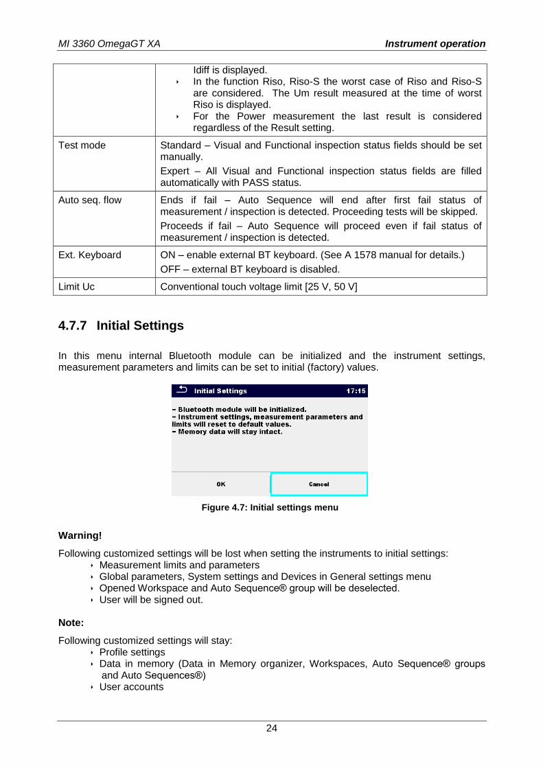
4.7.7 Initial Settings
In this menu internal Bluetooth module can be initialized and the instrument settings, measurement parameters and limits can be set to initial (factory) values.
Figure 4.7: Initial settings menu
Warning!
Following customized settings will be lost when setting the instruments to initial settings: Measurement limits and parameters Global parameters, System settings and Devices in General settings menu Opened Workspace and Auto Sequence® group will be deselected. User will be signed out.
Note:
Following customized settings will stay: Profile settings Data in memory (Data in Memory organizer, Workspaces, Auto Sequence® groups
and Auto Sequences®) User accounts
MI 3360 OmegaGT XA Instrument operation
25
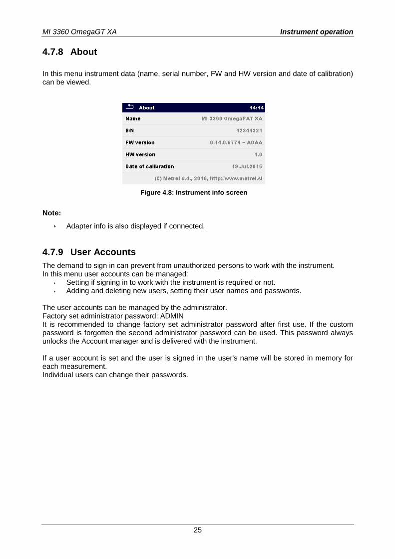
4.7.8 About
In this menu instrument data (name, serial number, FW and HW version and date of calibration) can be viewed.
Figure 4.8: Instrument info screen
Note:
Adapter info is also displayed if connected.
4.7.9 User Accounts
The demand to sign in can prevent from unauthorized persons to work with the instrument. In this menu user accounts can be managed:
Setting if signing in to work with the instrument is required or not. Adding and deleting new users, setting their user names and passwords.
The user accounts can be managed by the administrator. Factory set administrator password: ADMIN It is recommended to change factory set administrator password after first use. If the custom password is forgotten the second administrator password can be used. This password always unlocks the Account manager and is delivered with the instrument. If a user account is set and the user is signed in the user's name will be stored in memory for each measurement. Individual users can change their passwords.
MI 3360 OmegaGT XA Instrument operation
26
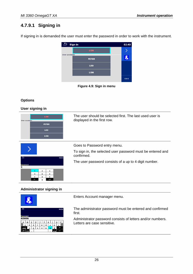
4.7.9.1 Signing in
If signing in is demanded the user must enter the password in order to work with the instrument.
Figure 4.9: Sign in menu
Options User signing in
The user should be selected first. The last used user is displayed in the first row.
Goes to Password entry menu.
To sign in, the selected user password must be entered and confirmed.
The user password consists of a up to 4 digit number.
Administrator signing in
Enters Account manager menu.
The administrator password must be entered and confirmed first.
Administrator password consists of letters and/or numbers. Letters are case sensitive.
MI 3360 OmegaGT XA Instrument operation
27
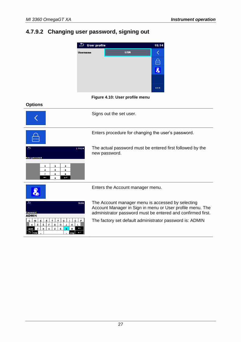
4.7.9.2 Changing user password, signing out
Figure 4.10: User profile menu
Options
Signs out the set user.
Enters procedure for changing the user’s password.
The actual password must be entered first followed by the new password.
Enters the Account manager menu.
The Account manager menu is accessed by selecting Account Manager in Sign in menu or User profile menu. The administrator password must be entered and confirmed first.
The factory set default administrator password is: ADMIN
MI 3360 OmegaGT XA Instrument operation
28
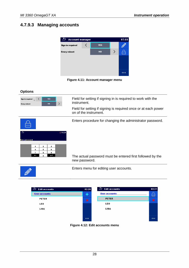
4.7.9.3 Managing accounts
Figure 4.11: Account manager menu
Options
Field for setting if signing in is required to work with the instrument.
Field for setting if signing is required once or at each power on of the instrument.
Enters procedure for changing the administrator password.
The actual password must be entered first followed by the new password.
Enters menu for editing user accounts.
Figure 4.12: Edit accounts menu
MI 3360 OmegaGT XA Instrument operation
29
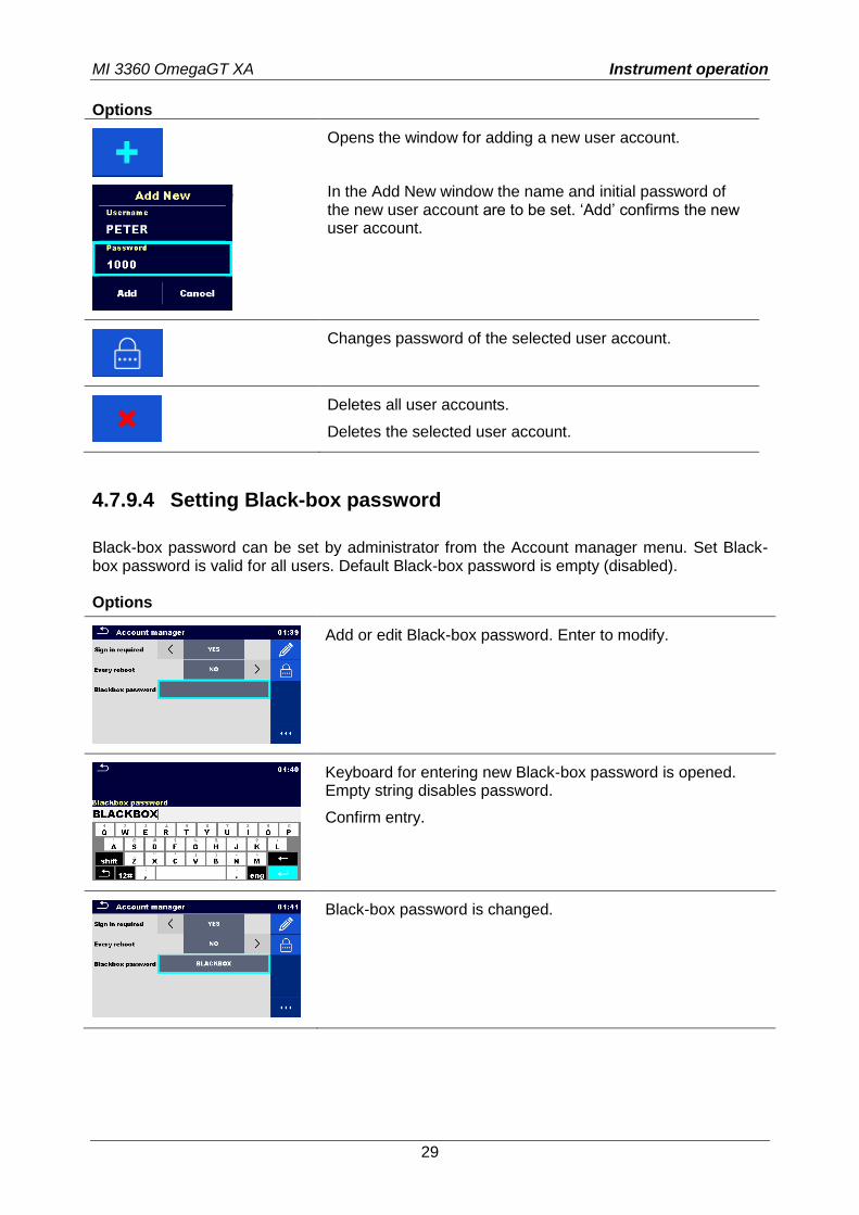
Options
Opens the window for adding a new user account.
In the Add New window the name and initial password of the new user account are to be set. ‘Add’ confirms the new user account.
Changes password of the selected user account.
Deletes all user accounts.
Deletes the selected user account.
4.7.9.4 Setting Black-box password
Black-box password can be set by administrator from the Account manager menu. Set Black-box password is valid for all users. Default Black-box password is empty (disabled). Options
Add or edit Black-box password. Enter to modify.
Keyboard for entering new Black-box password is opened. Empty string disables password.
Confirm entry.
Black-box password is changed.
MI 3360 OmegaGT XA Instrument operation
30
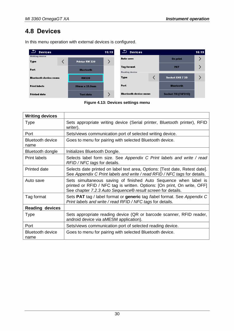
4.8 Devices
In this menu operation with external devices is configured.
Figure 4.13: Devices settings menu
Writing devices
Type Sets appropriate writing device (Serial printer, Bluetooth printer), RFID writer).
Port Sets/views communication port of selected writing device.
Bluetooth device name
Goes to menu for pairing with selected Bluetooth device.
Bluetooth dongle Initializes Bluetooth Dongle.
Print labels Selects label form size. See Appendix C Print labels and write / read RFID / NFC tags for details.
Printed date Selects date printed on label text area, Options: [Test date, Retest date]. See Appendix C Print labels and write / read RFID / NFC tags for details.
Auto save Sets simultaneous saving of finished Auto Sequence when label is printed or RFID / NFC tag is written. Options: [On print, On write, OFF] See chapter 7.2.3 Auto Sequence® result screen for details.
Tag format Sets PAT tag / label format or generic tag /label format. See Appendix C Print labels and write / read RFID / NFC tags for details.
Reading devices
Type Sets appropriate reading device (QR or barcode scanner, RFID reader, android device via aMESM application).
Port Sets/views communication port of selected reading device.
Bluetooth device name
Goes to menu for pairing with selected Bluetooth device.
MI 3360 OmegaGT XA Instrument operation
31
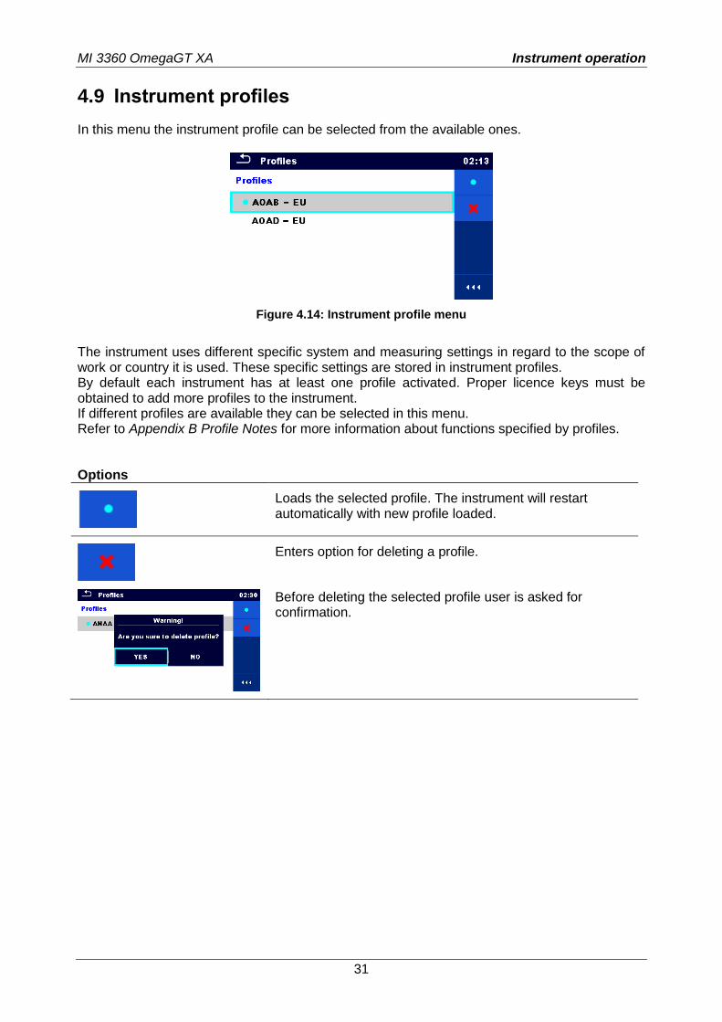
4.9 Instrument profiles
In this menu the instrument profile can be selected from the available ones.
Figure 4.14: Instrument profile menu
The instrument uses different specific system and measuring settings in regard to the scope of work or country it is used. These specific settings are stored in instrument profiles. By default each instrument has at least one profile activated. Proper licence keys must be obtained to add more profiles to the instrument. If different profiles are available they can be selected in this menu. Refer to Appendix B Profile Notes for more information about functions specified by profiles. Options
Loads the selected profile. The instrument will restart automatically with new profile loaded.
Enters option for deleting a profile.
Before deleting the selected profile user is asked for confirmation.
MI 3360 OmegaGT XA Instrument operation
32
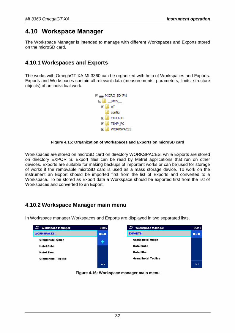
4.10 Workspace Manager
The Workspace Manager is intended to manage with different Workspaces and Exports stored on the microSD card.
4.10.1 Workspaces and Exports
The works with OmegaGT XA MI 3360 can be organized with help of Workspaces and Exports. Exports and Workspaces contain all relevant data (measurements, parameters, limits, structure objects) of an individual work.
Figure 4.15: Organization of Workspaces and Exports on microSD card
Workspaces are stored on microSD card on directory WORKSPACES, while Exports are stored on directory EXPORTS. Export files can be read by Metrel applications that run on other devices. Exports are suitable for making backups of important works or can be used for storage of works if the removable microSD card is used as a mass storage device. To work on the instrument an Export should be imported first from the list of Exports and converted to a Workspace. To be stored as Export data a Workspace should be exported first from the list of Workspaces and converted to an Export.
4.10.2 Workspace Manager main menu
In Workspace manager Workspaces and Exports are displayed in two separated lists.
Figure 4.16: Workspace manager main menu
MI 3360 OmegaGT XA Instrument operation
33
Options
List of Workspaces.
Displays a list of Exports.
Adds a new Workspace. Refer to Chapter 4.10.2.3 Adding a new Workspace for more information.
List of Exports.
Displays a list of Workspaces.
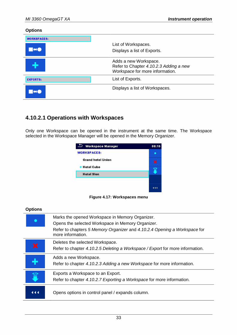
4.10.2.1 Operations with Workspaces
Only one Workspace can be opened in the instrument at the same time. The Workspace selected in the Workspace Manager will be opened in the Memory Organizer.
Figure 4.17: Workspaces menu
Options
Marks the opened Workspace in Memory Organizer.
Opens the selected Workspace in Memory Organizer.
Refer to chapters 5 Memory Organizer and 4.10.2.4 Opening a Workspace for more information.
Deletes the selected Workspace.
Refer to chapter 4.10.2.5 Deleting a Workspace / Export for more information.
Adds a new Workspace.
Refer to chapter 4.10.2.3 Adding a new Workspace for more information.
Exports a Workspace to an Export.
Refer to chapter 4.10.2.7 Exporting a Workspace for more information.
Opens options in control panel / expands column.
MI 3360 OmegaGT XA Instrument operation
34
4.10.2.2 Operations with Exports
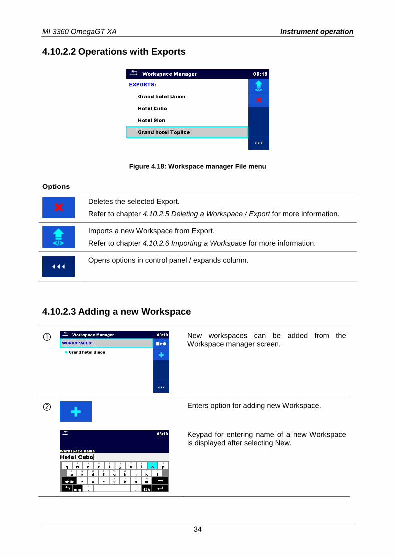
Figure 4.18: Workspace manager File menu
Options
Deletes the selected Export.
Refer to chapter 4.10.2.5 Deleting a Workspace / Export for more information.
Imports a new Workspace from Export.
Refer to chapter 4.10.2.6 Importing a Workspace for more information.
Opens options in control panel / expands column.
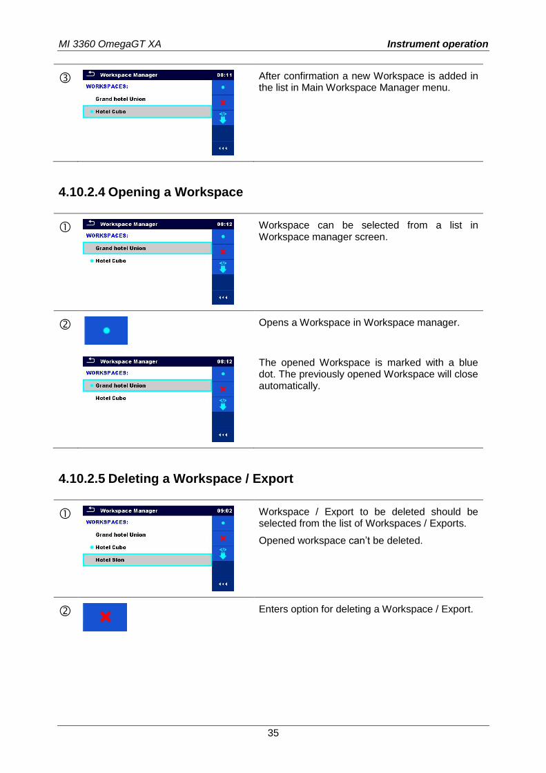
4.10.2.3 Adding a new Workspace
New workspaces can be added from the Workspace manager screen.
Enters option for adding new Workspace.
Keypad for entering name of a new Workspace is displayed after selecting New.
MI 3360 OmegaGT XA Instrument operation
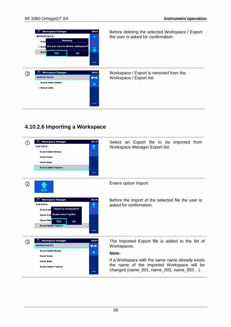
35
After confirmation a new Workspace is added in the list in Main Workspace Manager menu.
4.10.2.4 Opening a Workspace
Workspace can be selected from a list in Workspace manager screen.
Opens a Workspace in Workspace manager.
The opened Workspace is marked with a blue dot. The previously opened Workspace will close automatically.
4.10.2.5 Deleting a Workspace / Export
Workspace / Export to be deleted should be selected from the list of Workspaces / Exports.
Opened workspace can’t be deleted.
Enters option for deleting a Workspace / Export.
MI 3360 OmegaGT XA Instrument operation
36
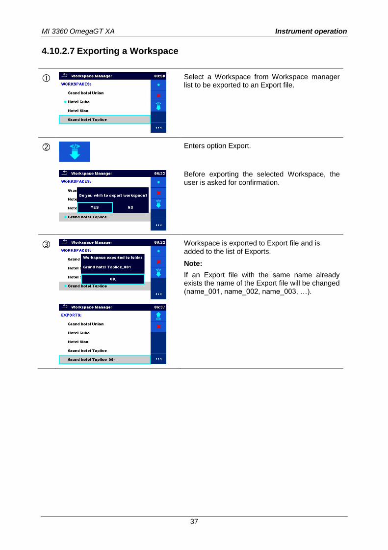
Before deleting the selected Workspace / Export the user is asked for confirmation.
Workspace / Export is removed from the Workspace / Export list.
4.10.2.6 Importing a Workspace
Select an Export file to be imported from Workspace Manager Export list.
Enters option Import.
Before the import of the selected file the user is asked for confirmation.
The Imported Export file is added to the list of Workspaces.
Note:
If a Workspace with the same name already exists the name of the imported Workspace will be changed (name_001, name_002, name_003…).
MI 3360 OmegaGT XA Instrument operation
37
4.10.2.7 Exporting a Workspace
Select a Workspace from Workspace manager list to be exported to an Export file.
Enters option Export.
Before exporting the selected Workspace, the user is asked for confirmation.
Workspace is exported to Export file and is added to the list of Exports.
Note:
If an Export file with the same name already exists the name of the Export file will be changed (name_001, name_002, name_003, …).
MI 3360 OmegaGT XA Instrument operation
38
4.11 Auto Sequence® groups
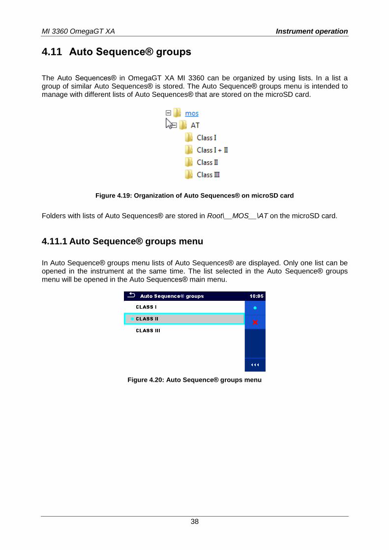
The Auto Sequences® in OmegaGT XA MI 3360 can be organized by using lists. In a list a group of similar Auto Sequences® is stored. The Auto Sequence® groups menu is intended to manage with different lists of Auto Sequences® that are stored on the microSD card.
Figure 4.19: Organization of Auto Sequences® on microSD card
Folders with lists of Auto Sequences® are stored in Root\__MOS__\AT on the microSD card.
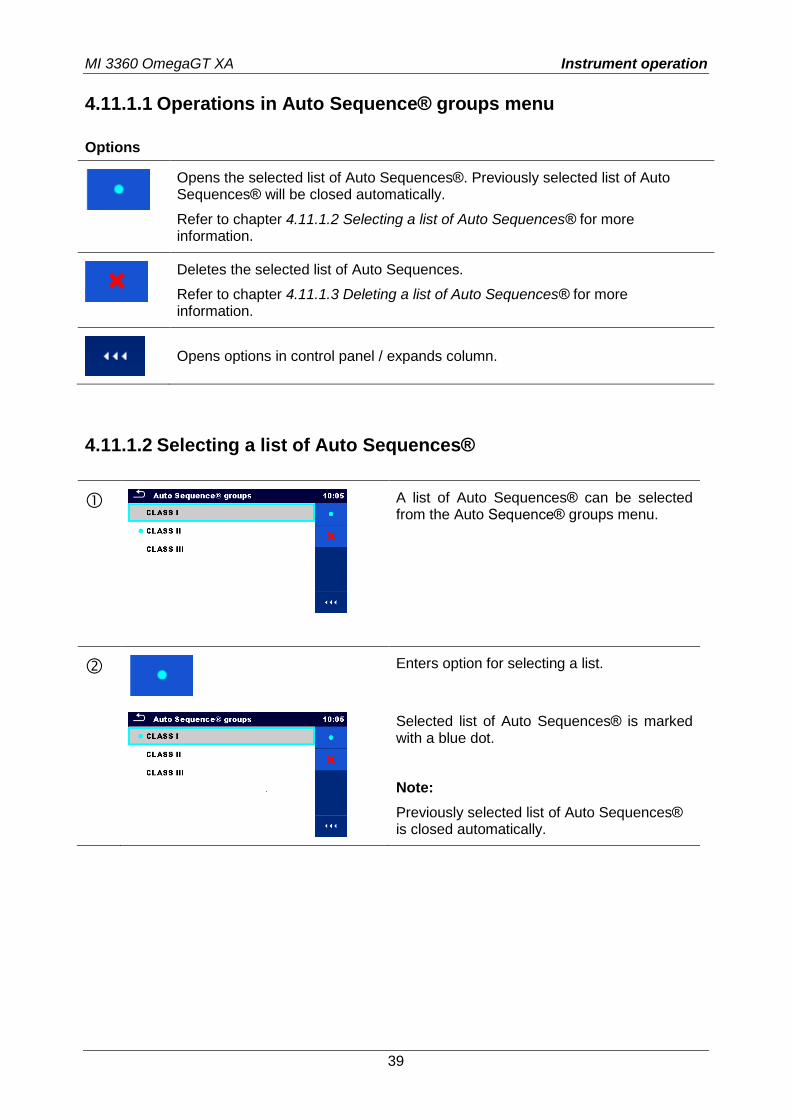
4.11.1 Auto Sequence® groups menu
In Auto Sequence® groups menu lists of Auto Sequences® are displayed. Only one list can be opened in the instrument at the same time. The list selected in the Auto Sequence® groups menu will be opened in the Auto Sequences® main menu.
Figure 4.20: Auto Sequence® groups menu
MI 3360 OmegaGT XA Instrument operation
39
4.11.1.1 Operations in Auto Sequence® groups menu
Options
Opens the selected list of Auto Sequences®. Previously selected list of Auto Sequences® will be closed automatically.
Refer to chapter 4.11.1.2 Selecting a list of Auto Sequences® for more information.
Deletes the selected list of Auto Sequences.
Refer to chapter 4.11.1.3 Deleting a list of Auto Sequences® for more information.
Opens options in control panel / expands column.
4.11.1.2 Selecting a list of Auto Sequences®
A list of Auto Sequences® can be selected from the Auto Sequence® groups menu.
Enters option for selecting a list.
Selected list of Auto Sequences® is marked with a blue dot.
Note:
Previously selected list of Auto Sequences® is closed automatically.
MI 3360 OmegaGT XA Instrument operation
40
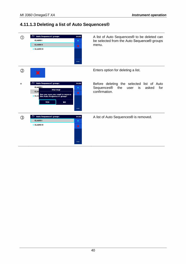
4.11.1.3 Deleting a list of Auto Sequences®
A list of Auto Sequences® to be deleted can be selected from the Auto Sequence® groups menu.
Enters option for deleting a list.
+
Before deleting the selected list of Auto Sequences® the user is asked for confirmation.
A list of Auto Sequences® is removed.
MI 3360 OmegaGT XA Memory Organizer
41
5 Memory Organizer
Memory Organizer is a tool for storing and working with test data.
5.1 Memory Organizer menu
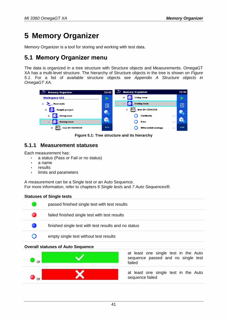
The data is organized in a tree structure with Structure objects and Measurements. OmegaGT XA has a multi-level structure. The hierarchy of Structure objects in the tree is shown on Figure 5.1. For a list of available structure objects see Appendix A Structure objects in OmegaGT XA.
Figure 5.1: Tree structure and its hierarchy
5.1.1 Measurement statuses
Each measurement has: a status (Pass or Fail or no status) a name results limits and parameters
A measurement can be a Single test or an Auto Sequence. For more information, refer to chapters 6 Single tests and 7 Auto Sequences®. Statuses of Single tests
passed finished single test with test results
failed finished single test with test results
finished single test with test results and no status
empty single test without test results
Overall statuses of Auto Sequence
or
at least one single test in the Auto sequence passed and no single test failed
or
at least one single test in the Auto sequence failed
MI 3360 OmegaGT XA Memory Organizer
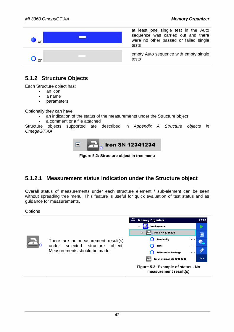
42
or
at least one single test in the Auto sequence was carried out and there were no other passed or failed single tests
or
empty Auto sequence with empty single tests
5.1.2 Structure Objects
Each Structure object has: an icon a name parameters
Optionally they can have:
an indication of the status of the measurements under the Structure object a comment or a file attached
Structure objects supported are described in Appendix A Structure objects in OmegaGT XA.
Figure 5.2: Structure object in tree menu
5.1.2.1 Measurement status indication under the Structure object
Overall status of measurements under each structure element / sub-element can be seen without spreading tree menu. This feature is useful for quick evaluation of test status and as guidance for measurements. Options
There are no measurement result(s) under selected structure object. Measurements should be made.
Figure 5.3: Example of status - No measurement result(s)
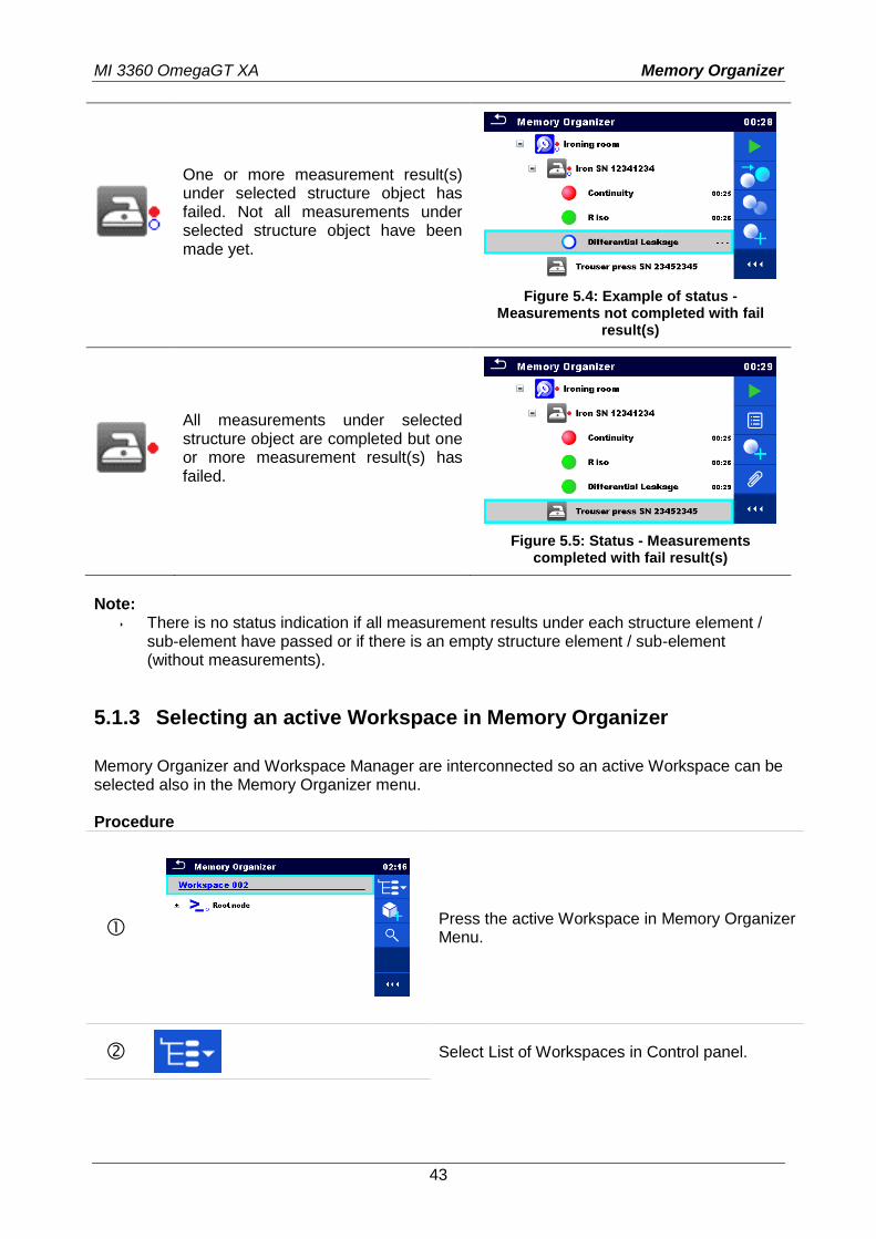
MI 3360 OmegaGT XA Memory Organizer
43
One or more measurement result(s) under selected structure object has failed. Not all measurements under selected structure object have been made yet.
Figure 5.4: Example of status - Measurements not completed with fail
result(s)
All measurements under selected structure object are completed but one or more measurement result(s) has failed.
Figure 5.5: Status - Measurements completed with fail result(s)
Note:
There is no status indication if all measurement results under each structure element / sub-element have passed or if there is an empty structure element / sub-element (without measurements).
5.1.3 Selecting an active Workspace in Memory Organizer
Memory Organizer and Workspace Manager are interconnected so an active Workspace can be selected also in the Memory Organizer menu. Procedure
Press the active Workspace in Memory Organizer Menu.
Select List of Workspaces in Control panel.
MI 3360 OmegaGT XA Memory Organizer
44
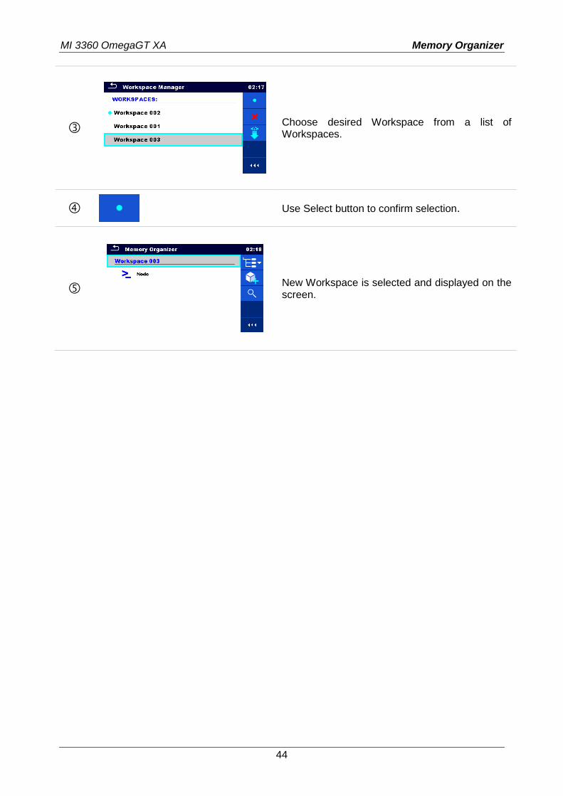
Choose desired Workspace from a list of Workspaces.
Use Select button to confirm selection.
New Workspace is selected and displayed on the screen.
MI 3360 OmegaGT XA Memory Organizer
45
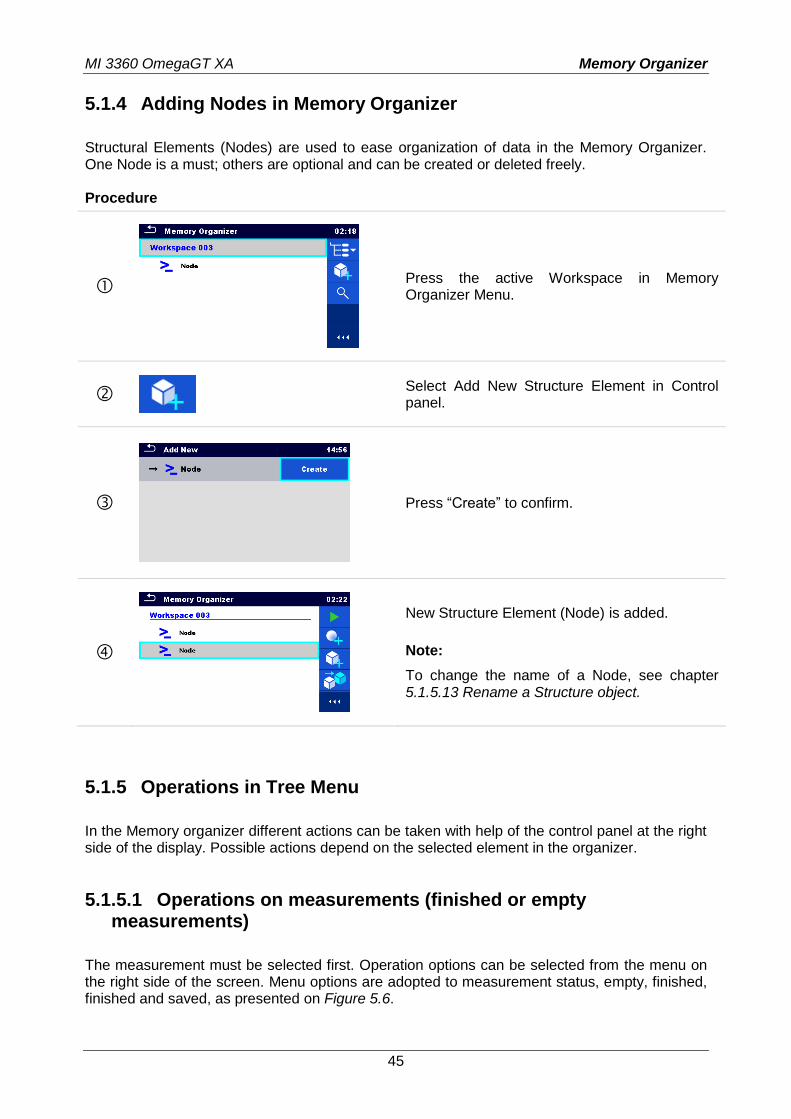
5.1.4 Adding Nodes in Memory Organizer
Structural Elements (Nodes) are used to ease organization of data in the Memory Organizer. One Node is a must; others are optional and can be created or deleted freely. Procedure
Press the active Workspace in Memory Organizer Menu.
Select Add New Structure Element in Control panel.
Press “Create” to confirm.
New Structure Element (Node) is added.
Note:
To change the name of a Node, see chapter 5.1.5.13 Rename a Structure object.
5.1.5 Operations in Tree Menu
In the Memory organizer different actions can be taken with help of the control panel at the right side of the display. Possible actions depend on the selected element in the organizer.
5.1.5.1 Operations on measurements (finished or empty measurements)
The measurement must be selected first. Operation options can be selected from the menu on the right side of the screen. Menu options are adopted to measurement status, empty, finished, finished and saved, as presented on Figure 5.6.
MI 3360 OmegaGT XA Memory Organizer
46
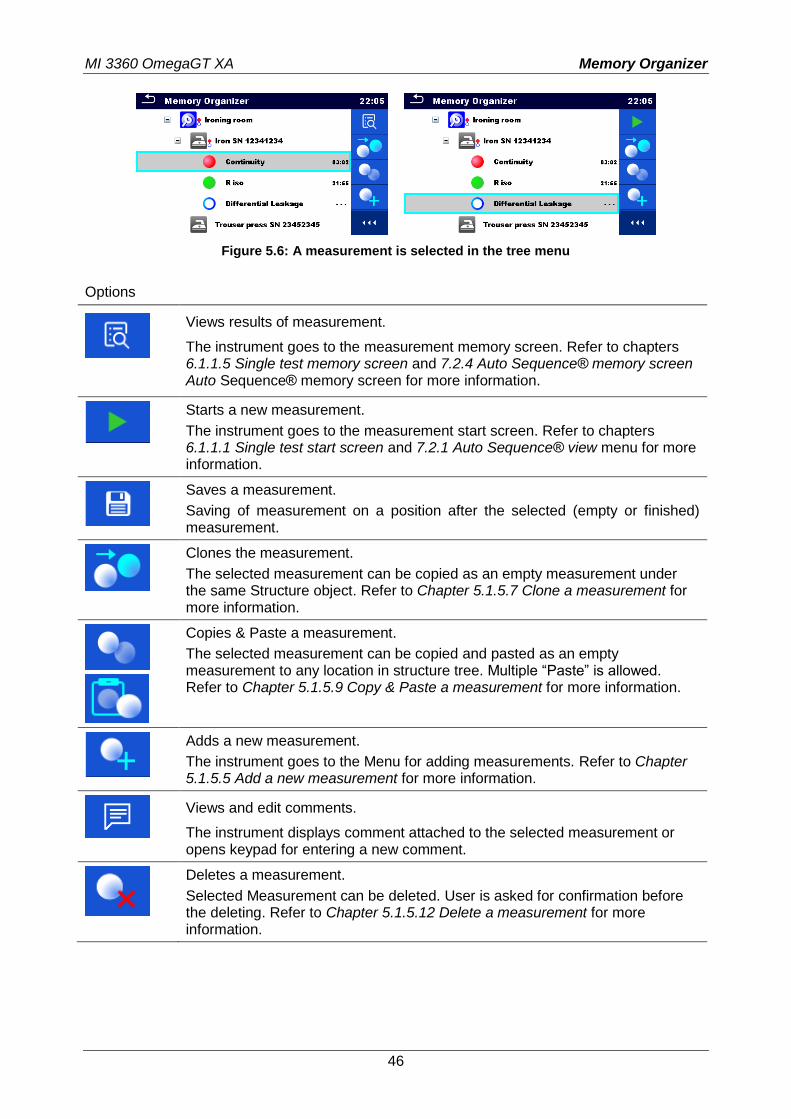
Figure 5.6: A measurement is selected in the tree menu
Options
Views results of measurement.
The instrument goes to the measurement memory screen. Refer to chapters 6.1.1.5 Single test memory screen and 7.2.4 Auto Sequence® memory screen Auto Sequence® memory screen for more information.
Starts a new measurement.
The instrument goes to the measurement start screen. Refer to chapters 6.1.1.1 Single test start screen and 7.2.1 Auto Sequence® view menu for more information.
Saves a measurement.
Saving of measurement on a position after the selected (empty or finished) measurement.
Clones the measurement.
The selected measurement can be copied as an empty measurement under the same Structure object. Refer to Chapter 5.1.5.7 Clone a measurement for more information.
Copies & Paste a measurement.
The selected measurement can be copied and pasted as an empty measurement to any location in structure tree. Multiple “Paste” is allowed. Refer to Chapter 5.1.5.9 Copy & Paste a measurement for more information.
Adds a new measurement.
The instrument goes to the Menu for adding measurements. Refer to Chapter 5.1.5.5 Add a new measurement for more information.
Views and edit comments.
The instrument displays comment attached to the selected measurement or opens keypad for entering a new comment.
Deletes a measurement.
Selected Measurement can be deleted. User is asked for confirmation before the deleting. Refer to Chapter 5.1.5.12 Delete a measurement for more information.
MI 3360 OmegaGT XA Memory Organizer
47
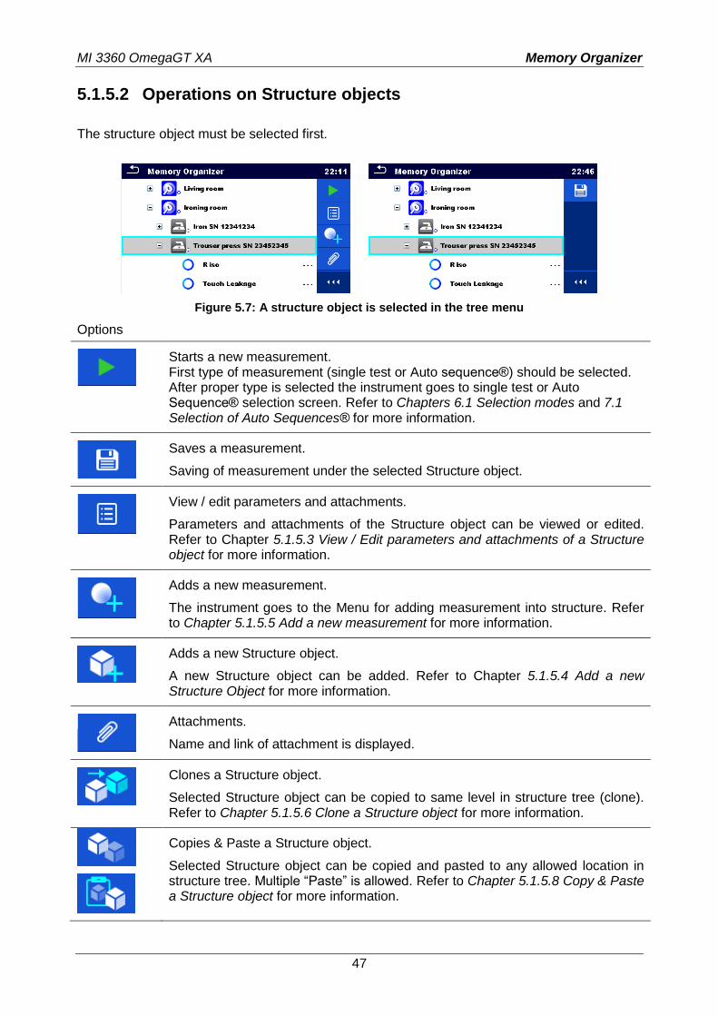
5.1.5.2 Operations on Structure objects
The structure object must be selected first.
Figure 5.7: A structure object is selected in the tree menu
Options
Starts a new measurement. First type of measurement (single test or Auto sequence®) should be selected. After proper type is selected the instrument goes to single test or Auto Sequence® selection screen. Refer to Chapters 6.1 Selection modes and 7.1 Selection of Auto Sequences® for more information.
Saves a measurement.
Saving of measurement under the selected Structure object.
View / edit parameters and attachments.
Parameters and attachments of the Structure object can be viewed or edited. Refer to Chapter 5.1.5.3 View / Edit parameters and attachments of a Structure object for more information.
Adds a new measurement.
The instrument goes to the Menu for adding measurement into structure. Refer to Chapter 5.1.5.5 Add a new measurement for more information.
Adds a new Structure object.
A new Structure object can be added. Refer to Chapter 5.1.5.4 Add a new Structure Object for more information.
Attachments.
Name and link of attachment is displayed.
Clones a Structure object.
Selected Structure object can be copied to same level in structure tree (clone). Refer to Chapter 5.1.5.6 Clone a Structure object for more information.
Copies & Paste a Structure object.
Selected Structure object can be copied and pasted to any allowed location in structure tree. Multiple “Paste” is allowed. Refer to Chapter 5.1.5.8 Copy & Paste a Structure object for more information.
MI 3360 OmegaGT XA Memory Organizer
48
Cut & Paste a Structure.
Selected Structure with child items (sub-structures and measurements) can be moved to any allowed location in structure tree. Refer to chapter 5.1.5.10 Cut & Paste a Structure object with sub-items for more information.
Views and edit comments.
The instrument displays comment attached to the selected Structure object or opens keypad for entering a new comment.
Deletes a Structure object.
Selected Structure object and sub-elements can be deleted. User is asked for confirmation before the deleting. Refer to Chapter 5.1.5.11 Delete a Structure object for more information.
Renames a Structure object.
Selected Structure object can be renamed via keypad. Refer to Chapter 5.1.5.13 Rename a Structure object for more information.
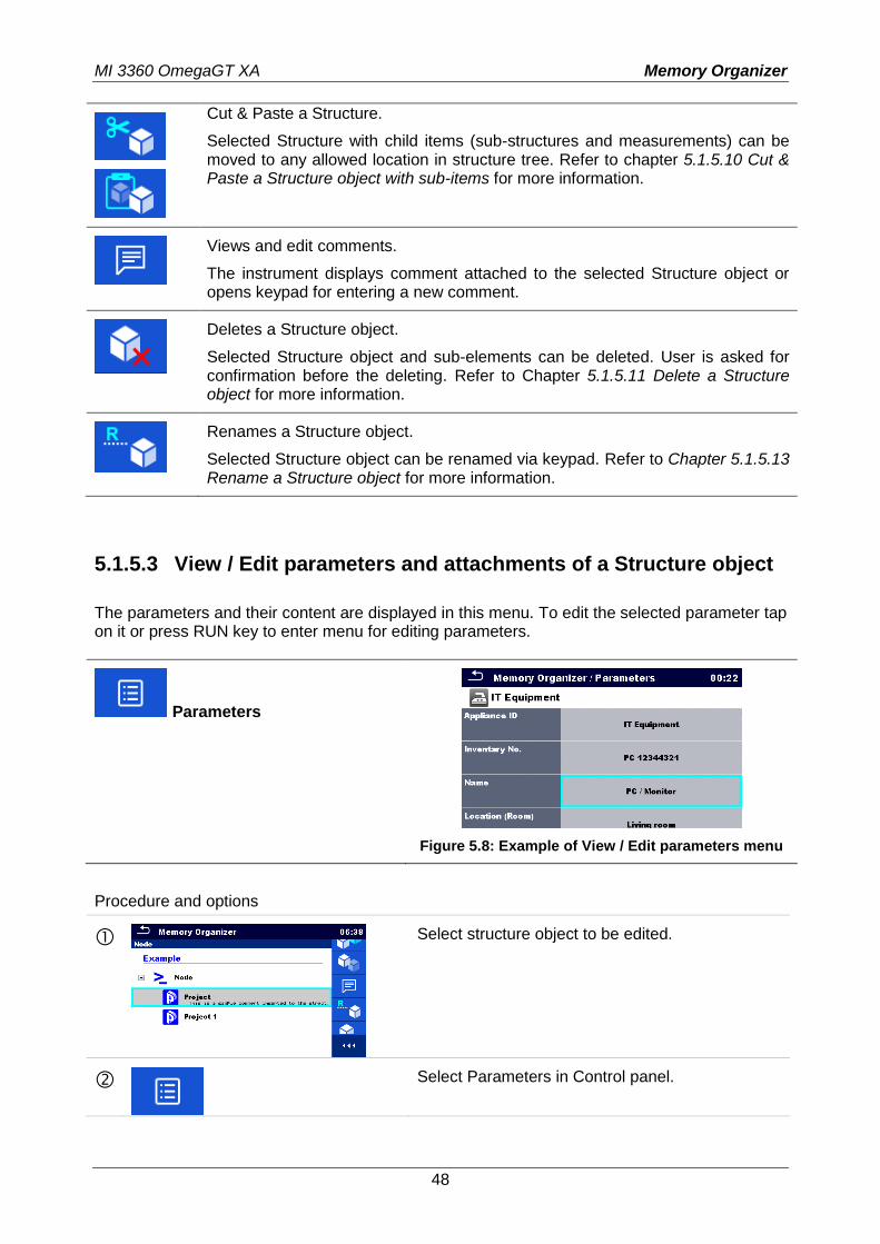
5.1.5.3 View / Edit parameters and attachments of a Structure object
The parameters and their content are displayed in this menu. To edit the selected parameter tap on it or press RUN key to enter menu for editing parameters.
Parameters
Figure 5.8: Example of View / Edit parameters menu
Procedure and options
Select structure object to be edited.
Select Parameters in Control panel.
MI 3360 OmegaGT XA Memory Organizer
49
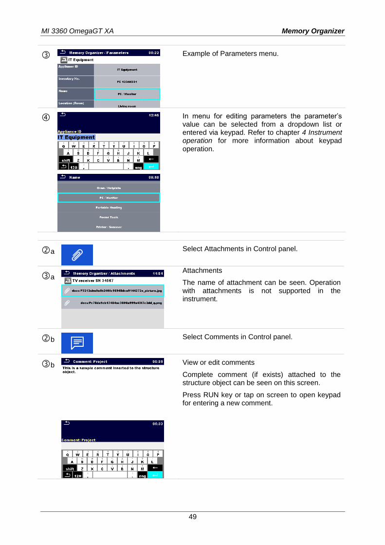
Example of Parameters menu.
In menu for editing parameters the parameter’s value can be selected from a dropdown list or entered via keypad. Refer to chapter 4 Instrument operation for more information about keypad operation.
a
Select Attachments in Control panel.
a
Attachments
The name of attachment can be seen. Operation with attachments is not supported in the instrument.
b
Select Comments in Control panel.
b
View or edit comments
Complete comment (if exists) attached to the structure object can be seen on this screen.
Press RUN key or tap on screen to open keypad for entering a new comment.
MI 3360 OmegaGT XA Memory Organizer
50
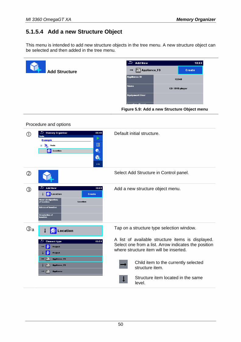
5.1.5.4 Add a new Structure Object
This menu is intended to add new structure objects in the tree menu. A new structure object can be selected and then added in the tree menu.
Add Structure
Figure 5.9: Add a new Structure Object menu
Procedure and options
Default initial structure.
Select Add Structure in Control panel.
Add a new structure object menu.
a
Tap on a structure type selection window.
A list of available structure items is displayed. Select one from a list. Arrow indicates the position where structure item will be inserted.
Child item to the currently selected structure item.
Structure item located in the same level.
MI 3360 OmegaGT XA Memory Organizer
51
b
In menu for editing name and parameters the parameter’s value can be selected from a dropdown list or entered via keypad. Refer to chapter 4 Instrument operation for more information about keypad operation.
Create new structure item.
New object added.
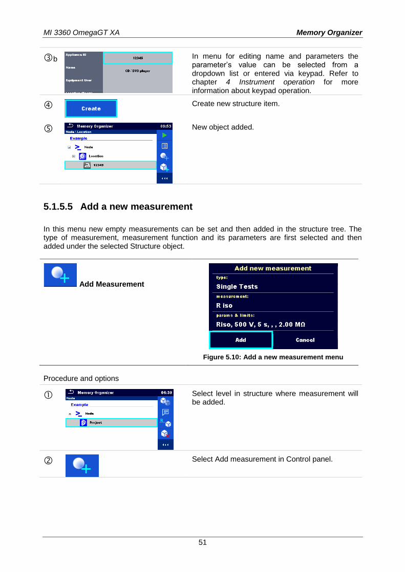
5.1.5.5 Add a new measurement
In this menu new empty measurements can be set and then added in the structure tree. The type of measurement, measurement function and its parameters are first selected and then added under the selected Structure object.
Add Measurement
Figure 5.10: Add a new measurement menu
Procedure and options
Select level in structure where measurement will be added.
Select Add measurement in Control panel.
MI 3360 OmegaGT XA Memory Organizer
52
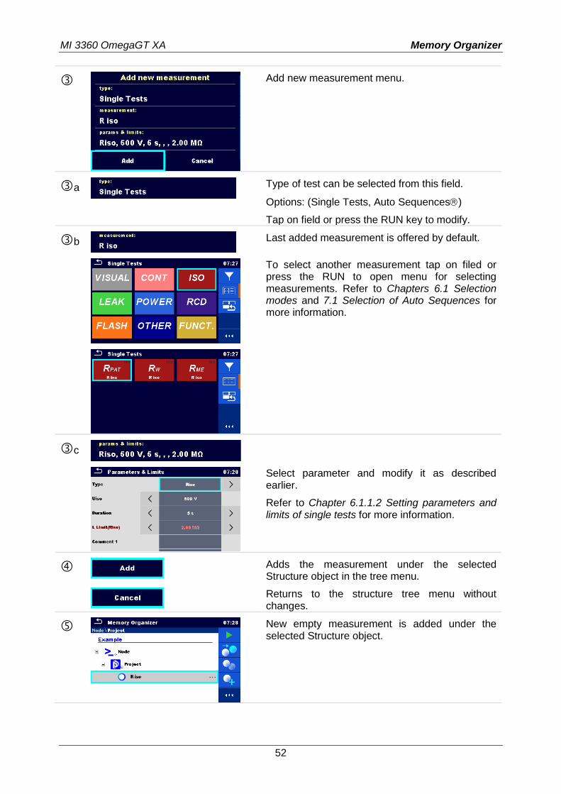
Add new measurement menu.
a
Type of test can be selected from this field.
Options: (Single Tests, Auto Sequences)
Tap on field or press the RUN key to modify.
b
Last added measurement is offered by default.
To select another measurement tap on filed or press the RUN to open menu for selecting measurements. Refer to Chapters 6.1 Selection modes and 7.1 Selection of Auto Sequences for more information.
c
Select parameter and modify it as described earlier.
Refer to Chapter 6.1.1.2 Setting parameters and limits of single tests for more information.
Adds the measurement under the selected Structure object in the tree menu.
Returns to the structure tree menu without changes.
New empty measurement is added under the selected Structure object.
MI 3360 OmegaGT XA Memory Organizer
53
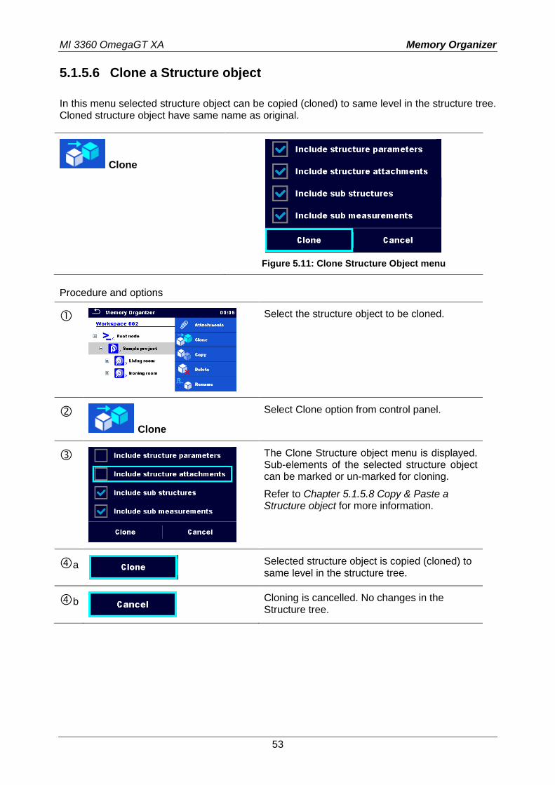
5.1.5.6 Clone a Structure object
In this menu selected structure object can be copied (cloned) to same level in the structure tree. Cloned structure object have same name as original.
Clone
Figure 5.11: Clone Structure Object menu
Procedure and options
Select the structure object to be cloned.
Clone
Select Clone option from control panel.
The Clone Structure object menu is displayed. Sub-elements of the selected structure object can be marked or un-marked for cloning.
Refer to Chapter 5.1.5.8 Copy & Paste a Structure object for more information.
a
Selected structure object is copied (cloned) to same level in the structure tree.
b
Cloning is cancelled. No changes in the Structure tree.
MI 3360 OmegaGT XA Memory Organizer
54
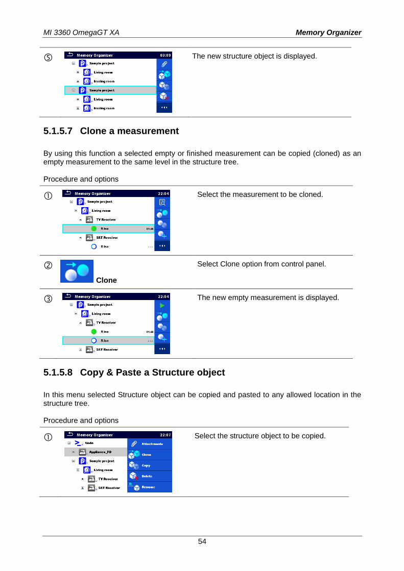
The new structure object is displayed.
5.1.5.7 Clone a measurement
By using this function a selected empty or finished measurement can be copied (cloned) as an empty measurement to the same level in the structure tree. Procedure and options
Select the measurement to be cloned.
Clone
Select Clone option from control panel.
The new empty measurement is displayed.
5.1.5.8 Copy & Paste a Structure object
In this menu selected Structure object can be copied and pasted to any allowed location in the structure tree. Procedure and options
Select the structure object to be copied.
MI 3360 OmegaGT XA Memory Organizer
55
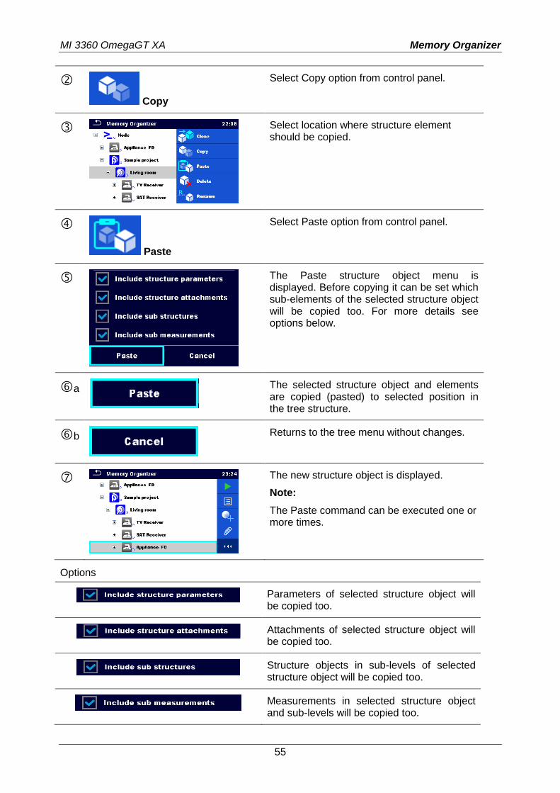
Copy
Select Copy option from control panel.
Select location where structure element should be copied.
Paste
Select Paste option from control panel.
The Paste structure object menu is displayed. Before copying it can be set which sub-elements of the selected structure object will be copied too. For more details see options below.
a
The selected structure object and elements are copied (pasted) to selected position in the tree structure.
b
Returns to the tree menu without changes.
The new structure object is displayed.
Note:
The Paste command can be executed one or more times.
Options
Parameters of selected structure object will be copied too.
Attachments of selected structure object will be copied too.
Structure objects in sub-levels of selected structure object will be copied too.
Measurements in selected structure object and sub-levels will be copied too.
MI 3360 OmegaGT XA Memory Organizer
56
5.1.5.9 Copy & Paste a measurement
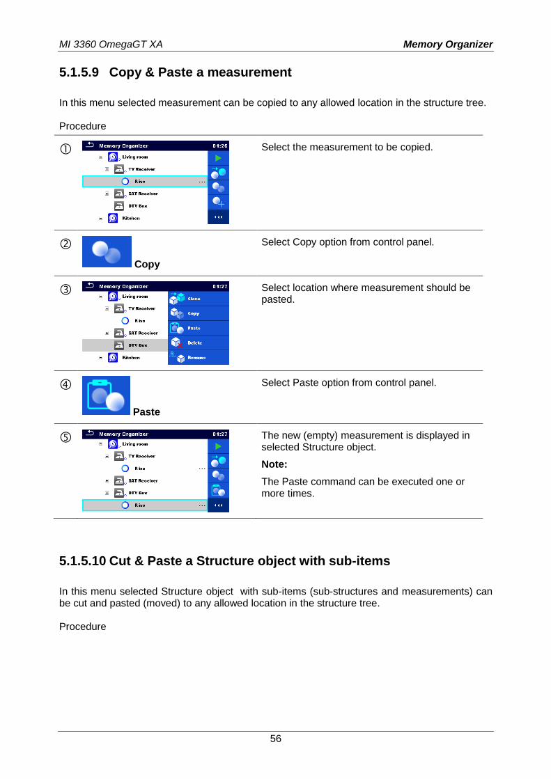
In this menu selected measurement can be copied to any allowed location in the structure tree. Procedure
Select the measurement to be copied.
Copy
Select Copy option from control panel.
Select location where measurement should be pasted.
Paste
Select Paste option from control panel.
The new (empty) measurement is displayed in selected Structure object.
Note:
The Paste command can be executed one or more times.
5.1.5.10 Cut & Paste a Structure object with sub-items
In this menu selected Structure object with sub-items (sub-structures and measurements) can be cut and pasted (moved) to any allowed location in the structure tree. Procedure
MI 3360 OmegaGT XA Memory Organizer
57
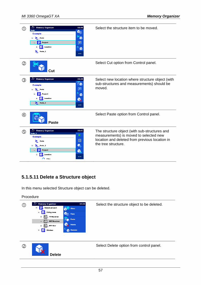
Select the structure item to be moved.
Cut
Select Cut option from Control panel.
Select new location where structure object (with sub-structures and measurements) should be moved.
Paste
Select Paste option from Control panel.
The structure object (with sub-structures and measurements) is moved to selected new location and deleted from previous location in the tree structure.
5.1.5.11 Delete a Structure object
In this menu selected Structure object can be deleted. Procedure
Select the structure object to be deleted.
Delete
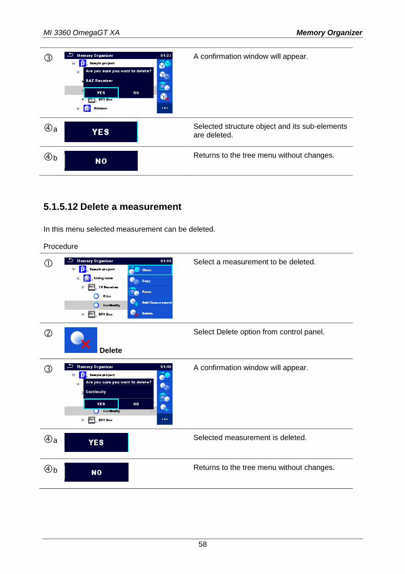
Select Delete option from control panel.
MI 3360 OmegaGT XA Memory Organizer
58
A confirmation window will appear.
a
Selected structure object and its sub-elements are deleted.
b
Returns to the tree menu without changes.
5.1.5.12 Delete a measurement
In this menu selected measurement can be deleted. Procedure
Select a measurement to be deleted.
Delete
Select Delete option from control panel.
A confirmation window will appear.
a
Selected measurement is deleted.
b
Returns to the tree menu without changes.
MI 3360 OmegaGT XA Memory Organizer
59
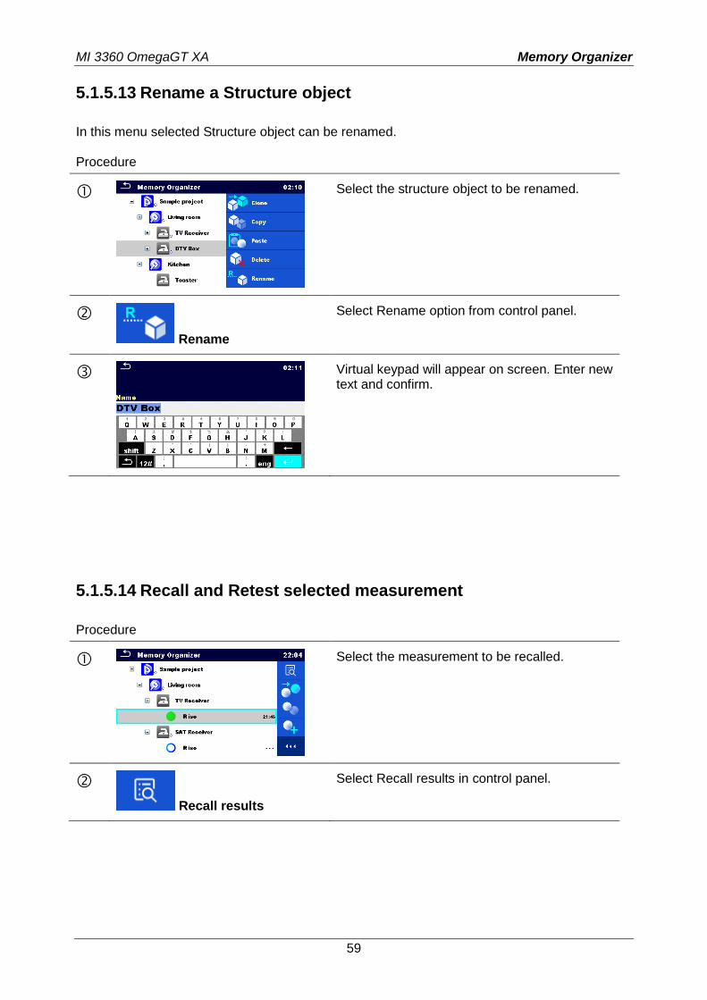
5.1.5.13 Rename a Structure object
In this menu selected Structure object can be renamed. Procedure
Select the structure object to be renamed.
Rename
Select Rename option from control panel.
Virtual keypad will appear on screen. Enter new text and confirm.
5.1.5.14 Recall and Retest selected measurement
Procedure
Select the measurement to be recalled.
Recall results
Select Recall results in control panel.
MI 3360 OmegaGT XA Memory Organizer
60
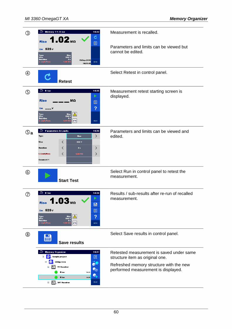
Measurement is recalled.
Parameters and limits can be viewed but cannot be edited.
Retest
Select Retest in control panel.
Measurement retest starting screen is displayed.
a
Parameters and limits can be viewed and edited.
Start Test
Select Run in control panel to retest the measurement.
Results / sub-results after re-run of recalled measurement.
Save results
Select Save results in control panel.
Retested measurement is saved under same structure item as original one.
Refreshed memory structure with the new performed measurement is displayed.
MI 3360 OmegaGT XA Memory Organizer
61
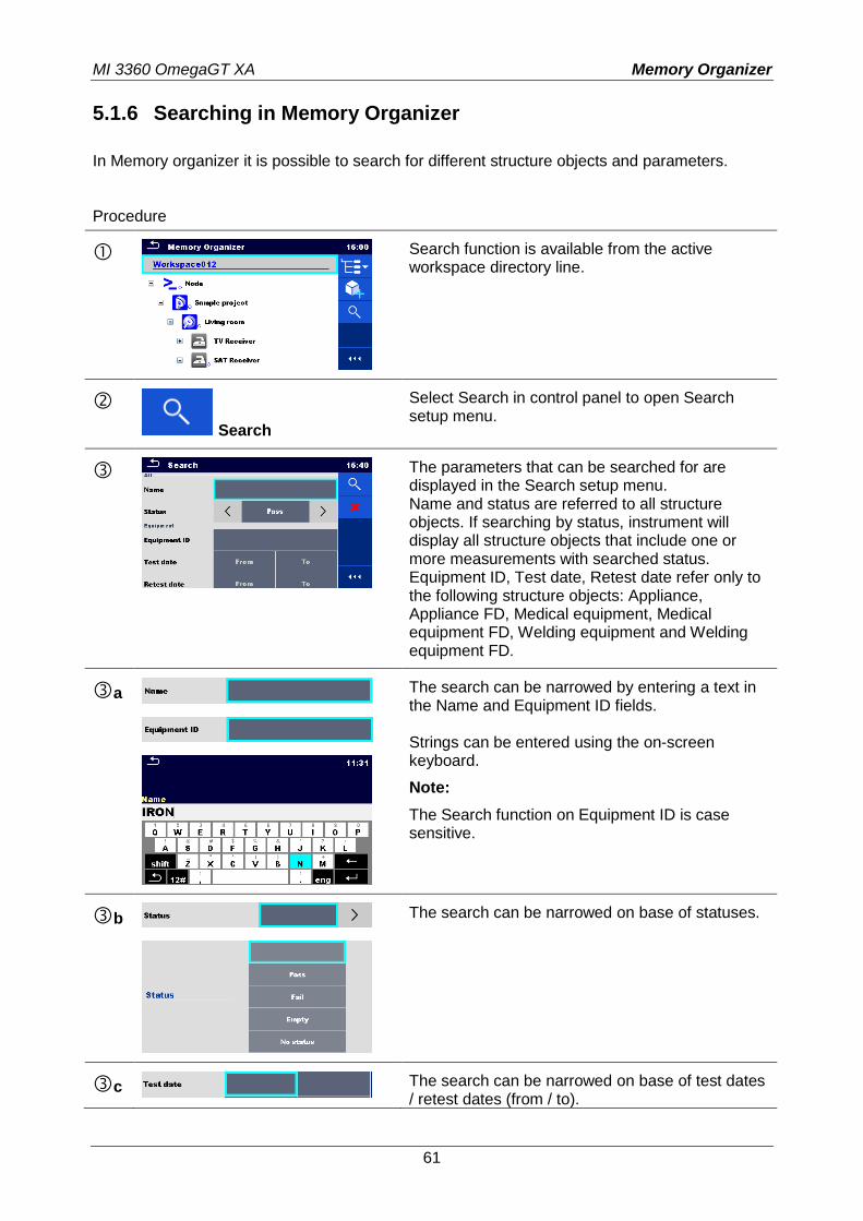
5.1.6 Searching in Memory Organizer
In Memory organizer it is possible to search for different structure objects and parameters. Procedure
Search function is available from the active workspace directory line.
Search
Select Search in control panel to open Search setup menu.
The parameters that can be searched for are displayed in the Search setup menu. Name and status are referred to all structure objects. If searching by status, instrument will display all structure objects that include one or more measurements with searched status. Equipment ID, Test date, Retest date refer only to the following structure objects: Appliance, Appliance FD, Medical equipment, Medical equipment FD, Welding equipment and Welding equipment FD.
a
The search can be narrowed by entering a text in the Name and Equipment ID fields. Strings can be entered using the on-screen keyboard.
Note:
The Search function on Equipment ID is case sensitive.
b
The search can be narrowed on base of statuses.
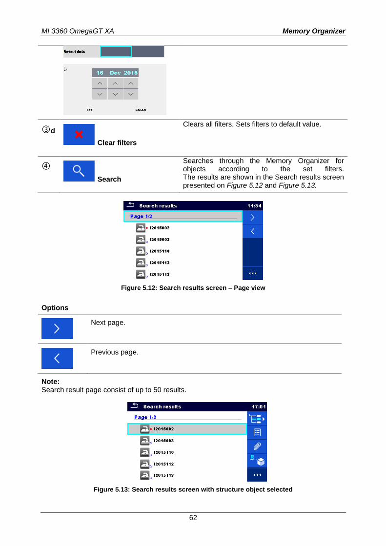
c The search can be narrowed on base of test dates / retest dates (from / to).
MI 3360 OmegaGT XA Memory Organizer
62
d Clear filters
Clears all filters. Sets filters to default value.
Search
Searches through the Memory Organizer for objects according to the set filters. The results are shown in the Search results screen presented on Figure 5.12 and Figure 5.13.
Figure 5.12: Search results screen – Page view
Options
Next page.
Previous page.
Note: Search result page consist of up to 50 results.
Figure 5.13: Search results screen with structure object selected
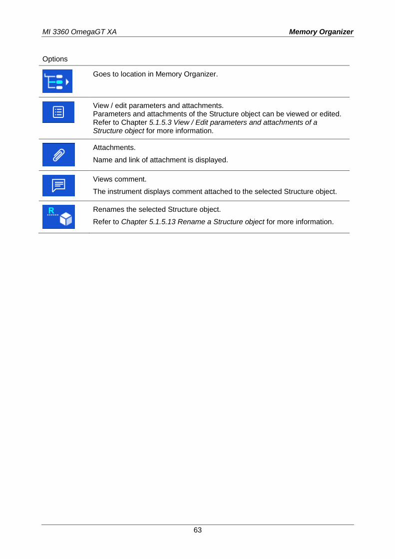
MI 3360 OmegaGT XA Memory Organizer
63
Options
Goes to location in Memory Organizer.
View / edit parameters and attachments. Parameters and attachments of the Structure object can be viewed or edited. Refer to Chapter 5.1.5.3 View / Edit parameters and attachments of a Structure object for more information.
Attachments.
Name and link of attachment is displayed.
Views comment.
The instrument displays comment attached to the selected Structure object.
Renames the selected Structure object.
Refer to Chapter 5.1.5.13 Rename a Structure object for more information.
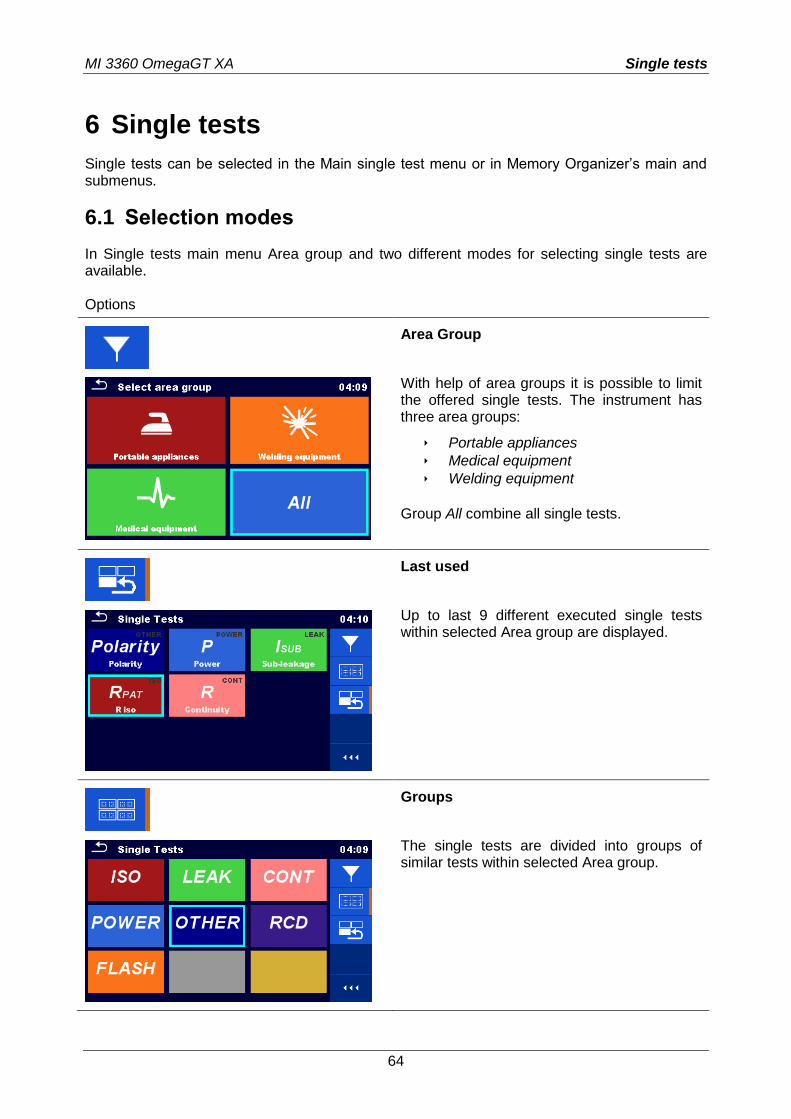
MI 3360 OmegaGT XA Single tests
64
6 Single tests
Single tests can be selected in the Main single test menu or in Memory Organizer’s main and submenus.
6.1 Selection modes
In Single tests main menu Area group and two different modes for selecting single tests are available. Options
Area Group
With help of area groups it is possible to limit the offered single tests. The instrument has three area groups:
Portable appliances Medical equipment Welding equipment
Group All combine all single tests.
Last used
Up to last 9 different executed single tests within selected Area group are displayed.
Groups
The single tests are divided into groups of similar tests within selected Area group.
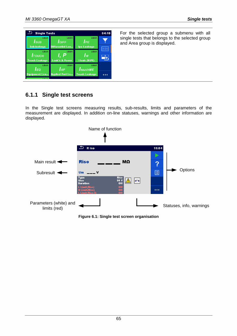
MI 3360 OmegaGT XA Single tests
65
For the selected group a submenu with all single tests that belongs to the selected group and Area group is displayed.
6.1.1 Single test screens
In the Single test screens measuring results, sub-results, limits and parameters of the measurement are displayed. In addition on-line statuses, warnings and other information are displayed.
Name of function
Main result
Subresult
Parameters (white) and
limits (red)Statuses, info, warnings
Options
Figure 6.1: Single test screen organisation
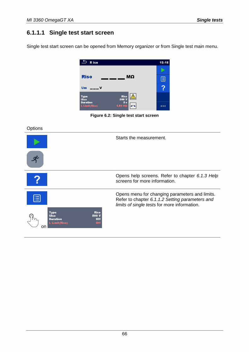
MI 3360 OmegaGT XA Single tests
66
6.1.1.1 Single test start screen
Single test start screen can be opened from Memory organizer or from Single test main menu.
Figure 6.2: Single test start screen
Options
Starts the measurement.
Opens help screens. Refer to chapter 6.1.3 Help screens for more information.
on
Opens menu for changing parameters and limits. Refer to chapter 6.1.1.2 Setting parameters and limits of single tests for more information.
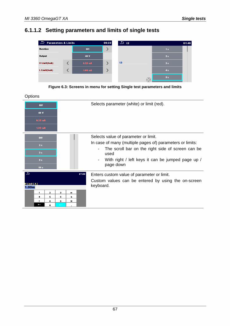
MI 3360 OmegaGT XA Single tests
67
6.1.1.2 Setting parameters and limits of single tests
Figure 6.3: Screens in menu for setting Single test parameters and limits
Options
Selects parameter (white) or limit (red).
Selects value of parameter or limit.
In case of many (multiple pages of) parameters or limits:
- The scroll bar on the right side of screen can be used
- With right / left keys it can be jumped page up / page down
Enters custom value of parameter or limit.
Custom values can be entered by using the on-screen keyboard.
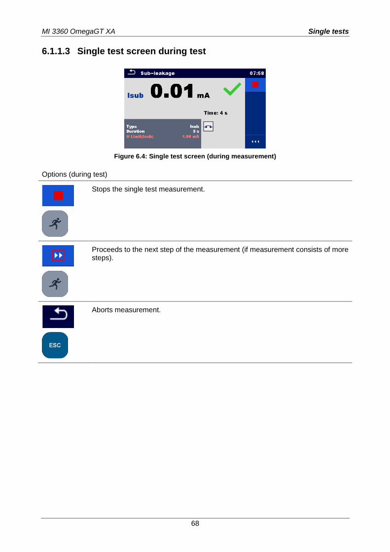
MI 3360 OmegaGT XA Single tests
68
6.1.1.3 Single test screen during test
Figure 6.4: Single test screen (during measurement)
Options (during test)
Stops the single test measurement.
Proceeds to the next step of the measurement (if measurement consists of more steps).
Aborts measurement.
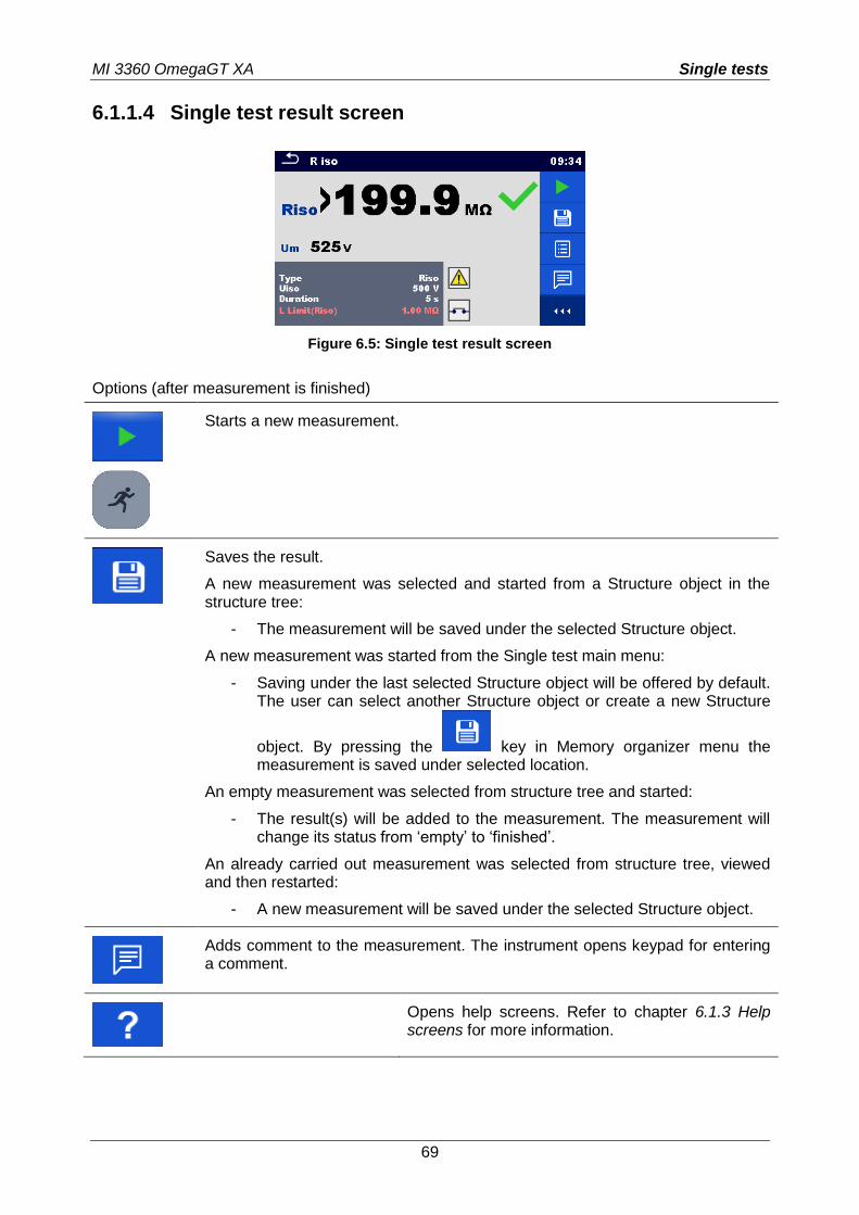
MI 3360 OmegaGT XA Single tests
69
6.1.1.4 Single test result screen
Figure 6.5: Single test result screen
Options (after measurement is finished)
Starts a new measurement.
Saves the result.
A new measurement was selected and started from a Structure object in the structure tree:
- The measurement will be saved under the selected Structure object.
A new measurement was started from the Single test main menu:
- Saving under the last selected Structure object will be offered by default. The user can select another Structure object or create a new Structure
object. By pressing the key in Memory organizer menu the measurement is saved under selected location.
An empty measurement was selected from structure tree and started:
- The result(s) will be added to the measurement. The measurement will change its status from ‘empty’ to ‘finished’.
An already carried out measurement was selected from structure tree, viewed and then restarted:
- A new measurement will be saved under the selected Structure object.
Adds comment to the measurement. The instrument opens keypad for entering a comment.
Opens help screens. Refer to chapter 6.1.3 Help screens for more information.
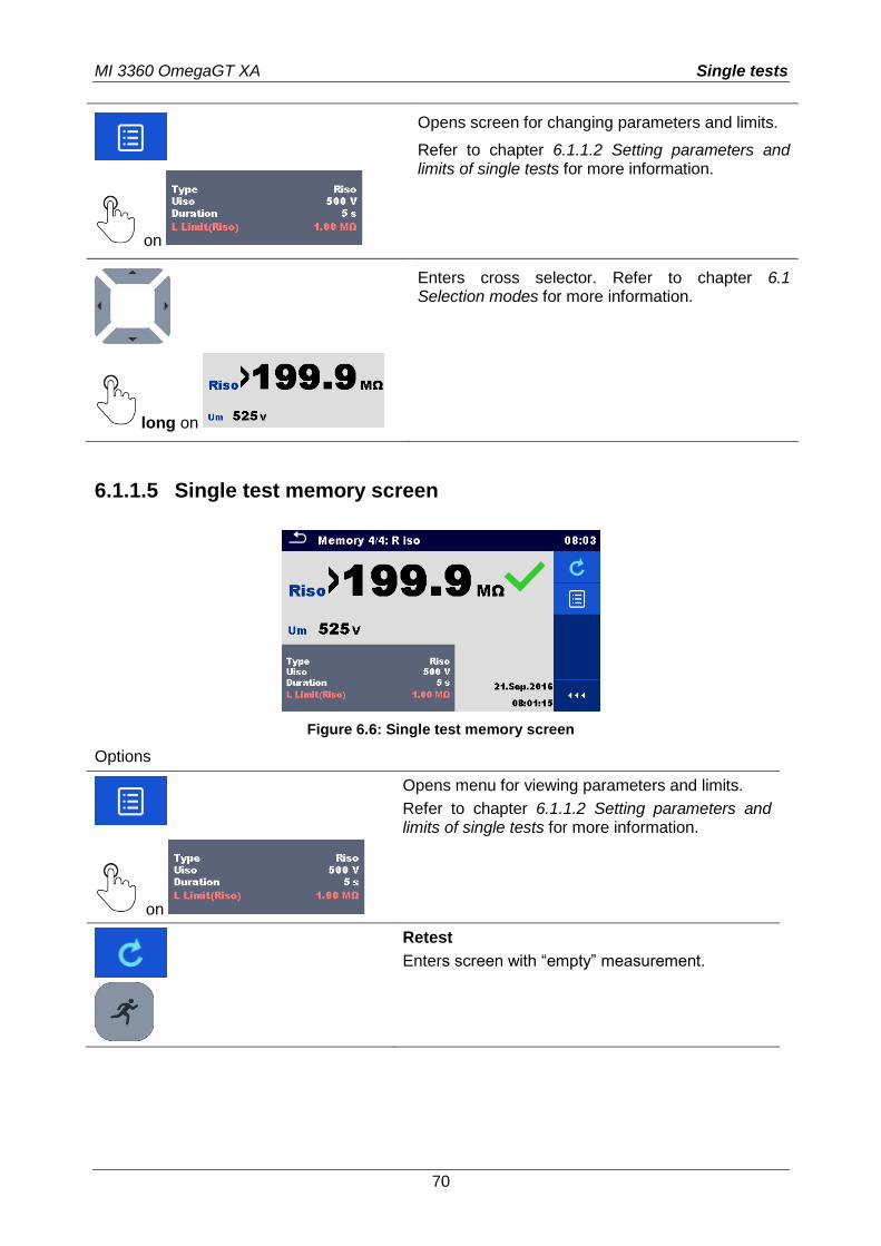
MI 3360 OmegaGT XA Single tests
70
on
Opens screen for changing parameters and limits.
Refer to chapter 6.1.1.2 Setting parameters and limits of single tests for more information.
long on
Enters cross selector. Refer to chapter 6.1 Selection modes for more information.
6.1.1.5 Single test memory screen
Figure 6.6: Single test memory screen
Options
on
Opens menu for viewing parameters and limits.
Refer to chapter 6.1.1.2 Setting parameters and limits of single tests for more information.
Retest
Enters screen with “empty” measurement.
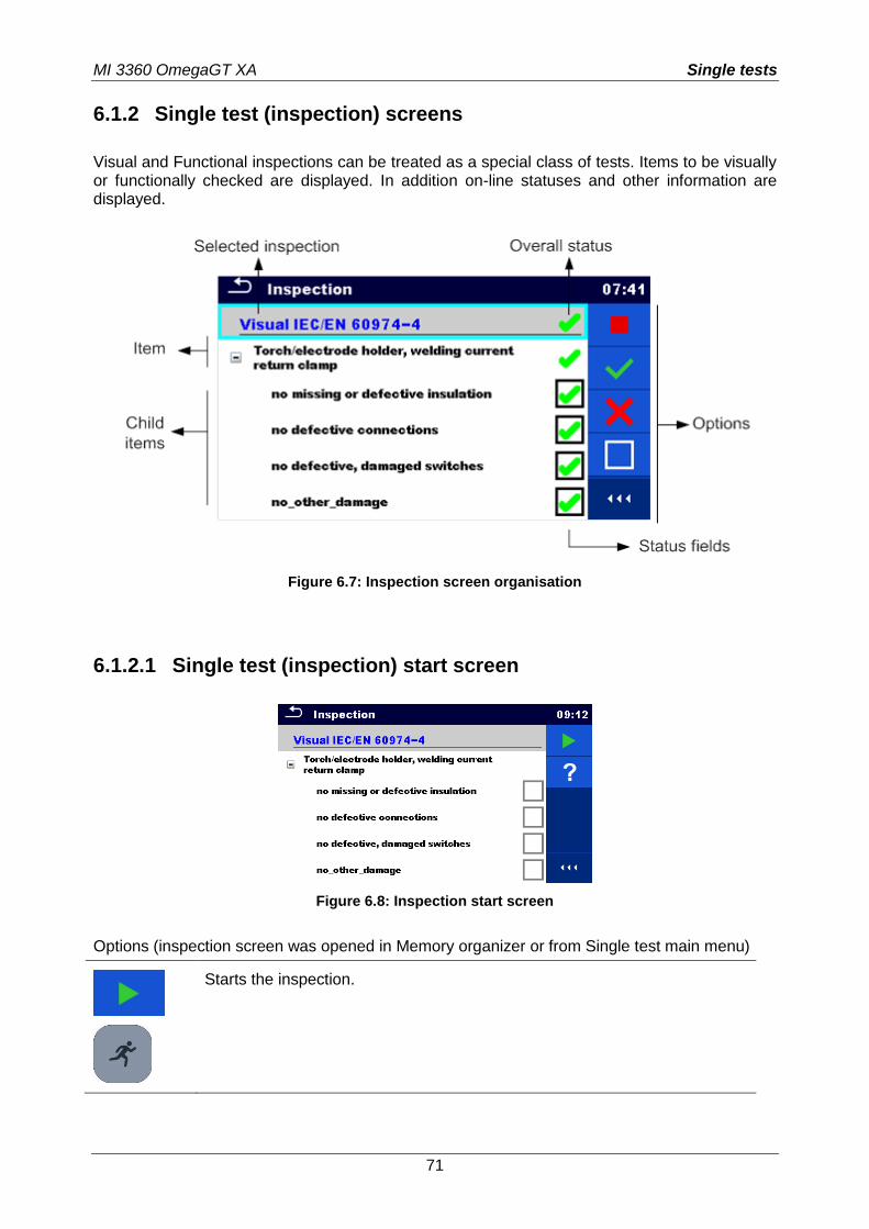
MI 3360 OmegaGT XA Single tests
71
6.1.2 Single test (inspection) screens
Visual and Functional inspections can be treated as a special class of tests. Items to be visually or functionally checked are displayed. In addition on-line statuses and other information are displayed.
Figure 6.7: Inspection screen organisation
6.1.2.1 Single test (inspection) start screen
Figure 6.8: Inspection start screen
Options (inspection screen was opened in Memory organizer or from Single test main menu)
Starts the inspection.
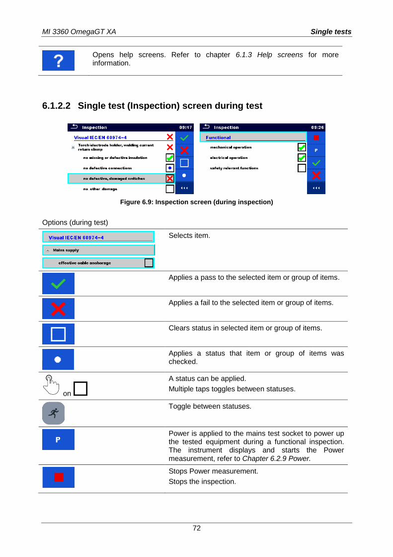
MI 3360 OmegaGT XA Single tests
72
Opens help screens. Refer to chapter 6.1.3 Help screens for more information.
6.1.2.2 Single test (Inspection) screen during test
Figure 6.9: Inspection screen (during inspection)
Options (during test)
Selects item.
Applies a pass to the selected item or group of items.
Applies a fail to the selected item or group of items.
Clears status in selected item or group of items.
Applies a status that item or group of items was checked.
on
A status can be applied.
Multiple taps toggles between statuses.
Toggle between statuses.
Power is applied to the mains test socket to power up the tested equipment during a functional inspection. The instrument displays and starts the Power measurement, refer to Chapter 6.2.9 Power.
Stops Power measurement.
Stops the inspection.
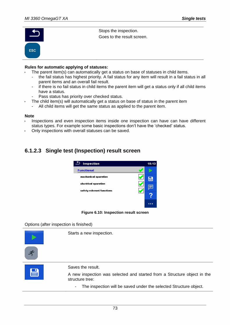
MI 3360 OmegaGT XA Single tests
73
Stops the inspection.
Goes to the result screen.
Rules for automatic applying of statuses: The parent item(s) can automatically get a status on base of statuses in child items.
- the fail status has highest priority. A fail status for any item will result in a fail status in all parent items and an overall fail result.
- if there is no fail status in child items the parent item will get a status only if all child items have a status.
- Pass status has priority over checked status. The child item(s) will automatically get a status on base of status in the parent item
- All child items will get the same status as applied to the parent item. Note Inspections and even inspection items inside one inspection can have can have different
status types. For example some basic inspections don’t have the ‘checked’ status. Only inspections with overall statuses can be saved.
6.1.2.3 Single test (Inspection) result screen
Figure 6.10: Inspection result screen
Options (after inspection is finished)
Starts a new inspection.
Saves the result.
A new inspection was selected and started from a Structure object in the structure tree:
- The inspection will be saved under the selected Structure object.
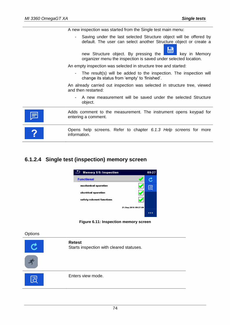
MI 3360 OmegaGT XA Single tests
74
A new inspection was started from the Single test main menu:
- Saving under the last selected Structure object will be offered by default. The user can select another Structure object or create a
new Structure object. By pressing the key in Memory organizer menu the inspection is saved under selected location.
An empty inspection was selected in structure tree and started:
- The result(s) will be added to the inspection. The inspection will change its status from ‘empty’ to ‘finished’.
An already carried out inspection was selected in structure tree, viewed and then restarted:
- A new measurement will be saved under the selected Structure object.
Adds comment to the measurement. The instrument opens keypad for entering a comment.
Opens help screens. Refer to chapter 6.1.3 Help screens for more information.
6.1.2.4 Single test (inspection) memory screen
Figure 6.11: Inspection memory screen
Options
Retest Starts inspection with cleared statuses.
Enters view mode.
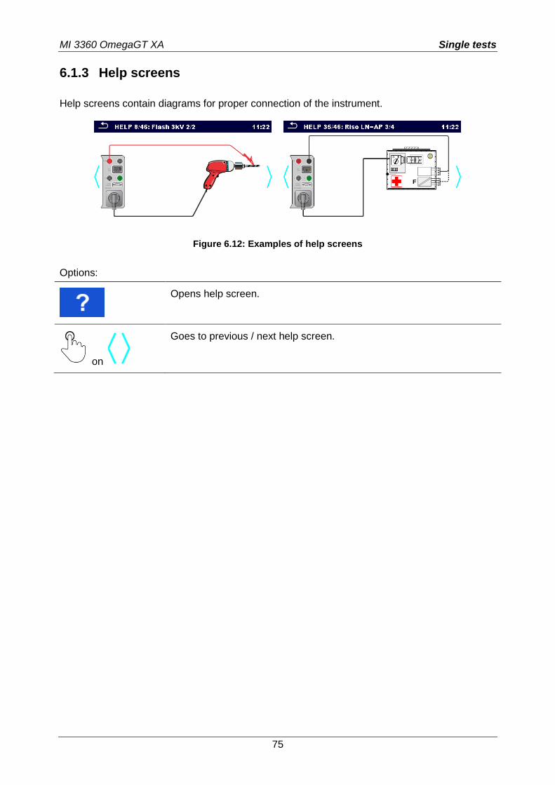
MI 3360 OmegaGT XA Single tests
75
6.1.3 Help screens
Help screens contain diagrams for proper connection of the instrument.
Figure 6.12: Examples of help screens
Options:
Opens help screen.
on
Goes to previous / next help screen.
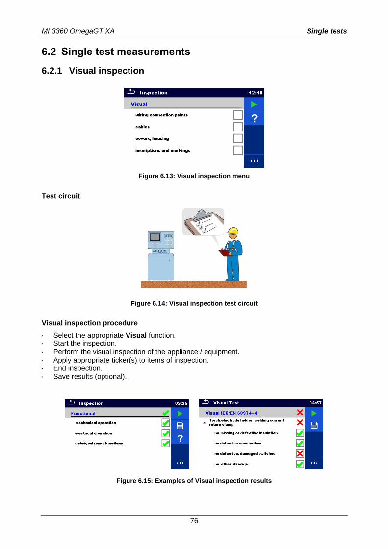
MI 3360 OmegaGT XA Single tests
76
6.2 Single test measurements
6.2.1 Visual inspection
Figure 6.13: Visual inspection menu
Test circuit
Figure 6.14: Visual inspection test circuit
Visual inspection procedure
Select the appropriate Visual function. Start the inspection. Perform the visual inspection of the appliance / equipment. Apply appropriate ticker(s) to items of inspection. End inspection. Save results (optional).
Figure 6.15: Examples of Visual inspection results
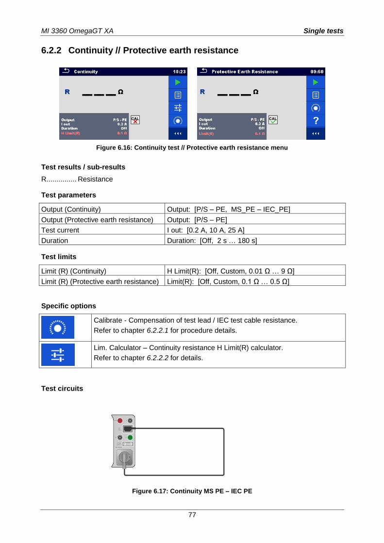
MI 3360 OmegaGT XA Single tests
77
6.2.2 Continuity // Protective earth resistance
Figure 6.16: Continuity test // Protective earth resistance menu
Test results / sub-results
R............... Resistance
Test parameters
Output (Continuity) Output: [P/S – PE, MS_PE – IEC_PE]
Output (Protective earth resistance) Output: [P/S – PE]
Test current I out: [0.2 A, 10 A, 25 A]
Duration Duration: [Off, 2 s … 180 s]
Test limits
Limit (R) (Continuity) H Limit(R): [Off, Custom, 0.01 Ω … 9 Ω]
Limit (R) (Protective earth resistance) Limit(R): [Off, Custom, 0.1 Ω … 0.5 Ω]
Specific options
Calibrate - Compensation of test lead / IEC test cable resistance.
Refer to chapter 6.2.2.1 for procedure details.
Lim. Calculator – Continuity resistance H Limit(R) calculator.
Refer to chapter 6.2.2.2 for details.
Test circuits
Figure 6.17: Continuity MS PE – IEC PE
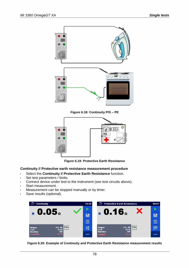
MI 3360 OmegaGT XA Single tests
78
Figure 6.18: Continuity P/S – PE
Figure 6.19: Protective Earth Resistance
Continuity // Protective earth resistance measurement procedure
Select the Continuity // Protective Earth Resistance function. Set test parameters / limits. Connect device under test to the instrument (see test circuits above). Start measurement. Measurement can be stopped manually or by timer. Save results (optional).
Figure 6.20: Example of Continuity and Protective Earth Resistance measurement results
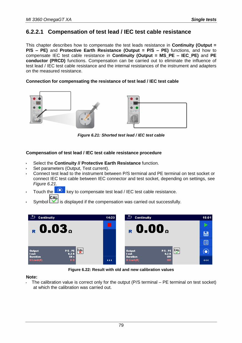
MI 3360 OmegaGT XA Single tests
79
6.2.2.1 Compensation of test lead / IEC test cable resistance
This chapter describes how to compensate the test leads resistance in Continuity (Output = P/S – PE) and Protective Earth Resistance (Output = P/S – PE) functions, and how to compensate IEC test cable resistance in Continuity (Output = MS_PE – IEC_PE) and PE conductor (PRCD) functions. Compensation can be carried out to eliminate the influence of test lead / IEC test cable resistance and the internal resistances of the instrument and adapters on the measured resistance. Connection for compensating the resistance of test lead / IEC test cable
Figure 6.21: Shorted test lead / IEC test cable
Compensation of test lead / IEC test cable resistance procedure Select the Continuity // Protective Earth Resistance function. Set parameters (Output, Test current). Connect test lead to the instrument between P/S terminal and PE terminal on test socket or
connect IEC test cable between IEC connector and test socket, depending on settings, see Figure 6.21.
Touch the key to compensate test lead / IEC test cable resistance.
Symbol is displayed if the compensation was carried out successfully.
Figure 6.22: Result with old and new calibration values
Note: The calibration value is correct only for the output (P/S terminal – PE terminal on test socket)
at which the calibration was carried out.
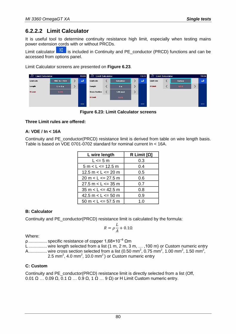
MI 3360 OmegaGT XA Single tests
80
6.2.2.2 Limit Calculator
It is useful tool to determine continuity resistance high limit, especially when testing mains power extension cords with or without PRCDs.
Limit calculator is included in Continuity and PE_conductor (PRCD) functions and can be accessed from options panel. Limit Calculator screens are presented on Figure 6.23.
Figure 6.23: Limit Calculator screens
Three Limit rules are offered:
A: VDE / In < 16A
Continuity and PE_conductor(PRCD) resistance limit is derived from table on wire length basis. Table is based on VDE 0701-0702 standard for nominal current In < 16A.
L wire length R Limit [Ω]
L <= 5 m 0.3
5 m < L <= 12.5 m 0.4
12.5 m < L <= 20 m 0.5
20 m < L <= 27.5 m 0.6
27.5 m < L <= 35 m 0.7
35 m < L <= 42.5 m 0.8
42.5 m < L <= 50 m 0.9
50 m < L <= 57.5 m 1.0
B: Calculator
Continuity and PE_conductor(PRCD) resistance limit is calculated by the formula:
𝑅 = 𝜌𝐿
𝐴+ 0.1Ω
Where: ρ ............... specific resistance of copper 1,68×10⁻⁸ Ωm L ............... wire length selected from a list (1 m, 2 m, 3 m, … ,100 m) or Custom numeric entry A ............... wire cross section selected from a list (0.50 mm2, 0.75 mm2, 1.00 mm2, 1.50 mm2,
2.5 mm2, 4.0 mm2, 10.0 mm2 ) or Custom numeric entry
C: Custom
Continuity and PE_conductor(PRCD) resistance limit is directly selected from a list (Off, 0.01 Ω … 0.09 Ω, 0.1 Ω … 0.9 Ω, 1 Ω … 9 Ω) or H Limit Custom numeric entry.
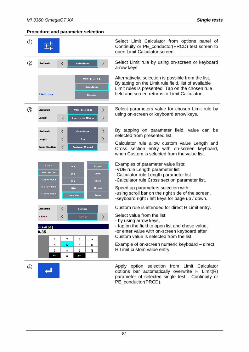
MI 3360 OmegaGT XA Single tests
81
Procedure and parameter selection
Select Limit Calculator from options panel of Continuity or PE_conductor(PRCD) test screen to open Limit Calculator screen.
Select Limit rule by using on-screen or keyboard arrow keys.
Alternatively, selection is possible from the list. By taping on the Limit rule field, list of available Limit rules is presented. Tap on the chosen rule field and screen returns to Limit Calculator.
Select parameters value for chosen Limit rule by using on-screen or keyboard arrow keys.
By tapping on parameter field, value can be selected from presented list.
Calculator rule allow custom value Length and Cross section entry with on-screen keyboard, when Custom is selected from the value list.
Examples of parameter value lists: -VDE rule Length parameter list -Calculator rule Length parameter list -Calculator rule Cross section parameter list.
Speed up parameters selection with: -using scroll bar on the right side of the screen, -keyboard right / left keys for page up / down.
Custom rule is intended for direct H Limit entry.
Select value from the list: - by using arrow keys, - tap on the field to open list and chose value, -or enter value with on-screen keyboard after Custom value is selected from the list.
Example of on-screen numeric keyboard – direct H Limit custom value entry.
Apply option selection from Limit Calculator options bar automatically overwrite H Limit(R) parameter of selected single test - Continuity or PE_conductor(PRCD).
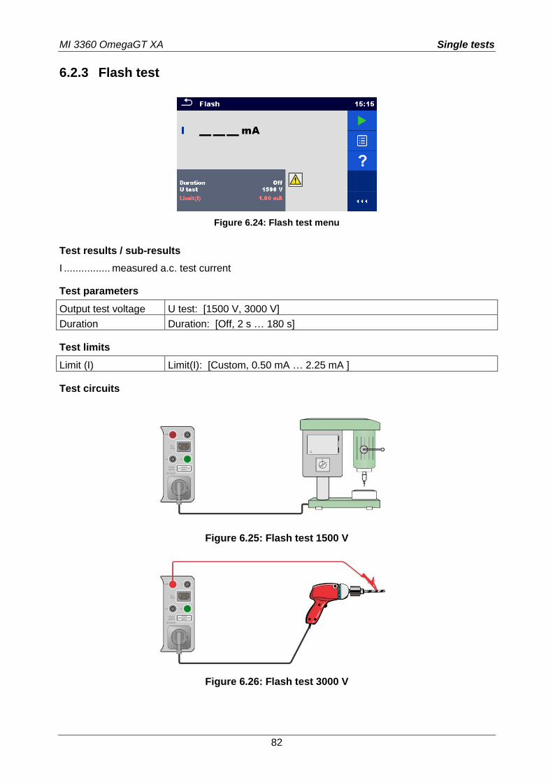
MI 3360 OmegaGT XA Single tests
82
6.2.3 Flash test
Figure 6.24: Flash test menu
Test results / sub-results
I ................ measured a.c. test current
Test parameters
Output test voltage U test: [1500 V, 3000 V]
Duration Duration: [Off, 2 s … 180 s]
Test limits
Limit (I) Limit(I): [Custom, 0.50 mA … 2.25 mA ]
Test circuits
Figure 6.25: Flash test 1500 V
Figure 6.26: Flash test 3000 V
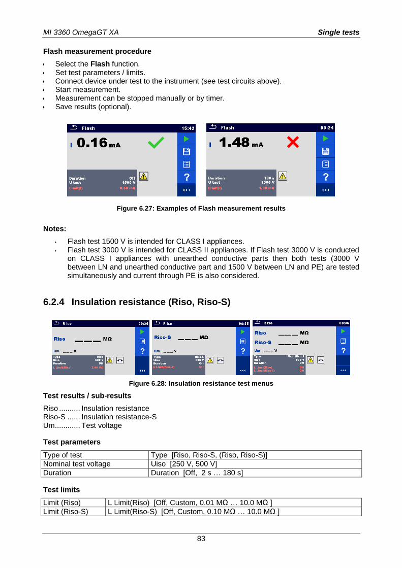
MI 3360 OmegaGT XA Single tests
83
Flash measurement procedure
Select the Flash function. Set test parameters / limits. Connect device under test to the instrument (see test circuits above). Start measurement. Measurement can be stopped manually or by timer. Save results (optional).
Figure 6.27: Examples of Flash measurement results
Notes:
Flash test 1500 V is intended for CLASS I appliances. Flash test 3000 V is intended for CLASS II appliances. If Flash test 3000 V is conducted
on CLASS I appliances with unearthed conductive parts then both tests (3000 V between LN and unearthed conductive part and 1500 V between LN and PE) are tested simultaneously and current through PE is also considered.
6.2.4 Insulation resistance (Riso, Riso-S)
Figure 6.28: Insulation resistance test menus
Test results / sub-results
Riso .......... Insulation resistance Riso-S ...... Insulation resistance-S Um ............ Test voltage
Test parameters
Type of test Type [Riso, Riso-S, (Riso, Riso-S)]
Nominal test voltage Uiso [250 V, 500 V]
Duration Duration [Off, 2 s … 180 s]
Test limits
Limit (Riso) L Limit(Riso) [Off, Custom, 0.01 MΩ … 10.0 MΩ ]
Limit (Riso-S) L Limit(Riso-S) [Off, Custom, 0.10 MΩ … 10.0 MΩ ]
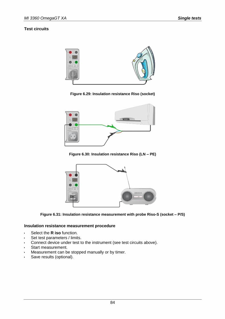
MI 3360 OmegaGT XA Single tests
84
Test circuits
Figure 6.29: Insulation resistance Riso (socket)
Figure 6.30: Insulation resistance Riso (LN – PE)
Figure 6.31: Insulation resistance measurement with probe Riso-S (socket – P/S)
Insulation resistance measurement procedure
Select the R iso function. Set test parameters / limits. Connect device under test to the instrument (see test circuits above). Start measurement. Measurement can be stopped manually or by timer. Save results (optional).
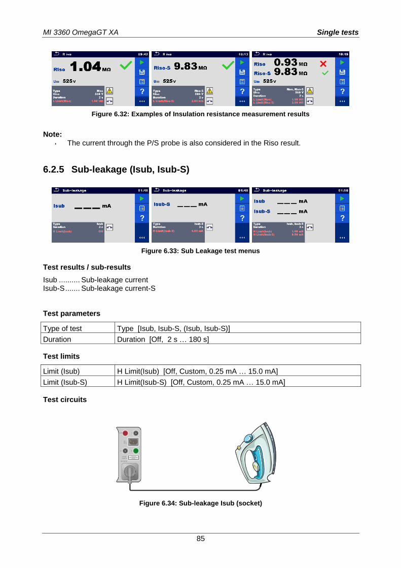
MI 3360 OmegaGT XA Single tests
85
Figure 6.32: Examples of Insulation resistance measurement results
Note: The current through the P/S probe is also considered in the Riso result.
6.2.5 Sub-leakage (Isub, Isub-S)
Figure 6.33: Sub Leakage test menus
Test results / sub-results
Isub .......... Sub-leakage current Isub-S ....... Sub-leakage current-S
Test parameters
Type of test Type [Isub, Isub-S, (Isub, Isub-S)]
Duration Duration [Off, 2 s … 180 s]
Test limits
Limit (Isub) H Limit(Isub) [Off, Custom, 0.25 mA … 15.0 mA]
Limit (Isub-S) H Limit(Isub-S) [Off, Custom, 0.25 mA … 15.0 mA]
Test circuits
Figure 6.34: Sub-leakage Isub (socket)
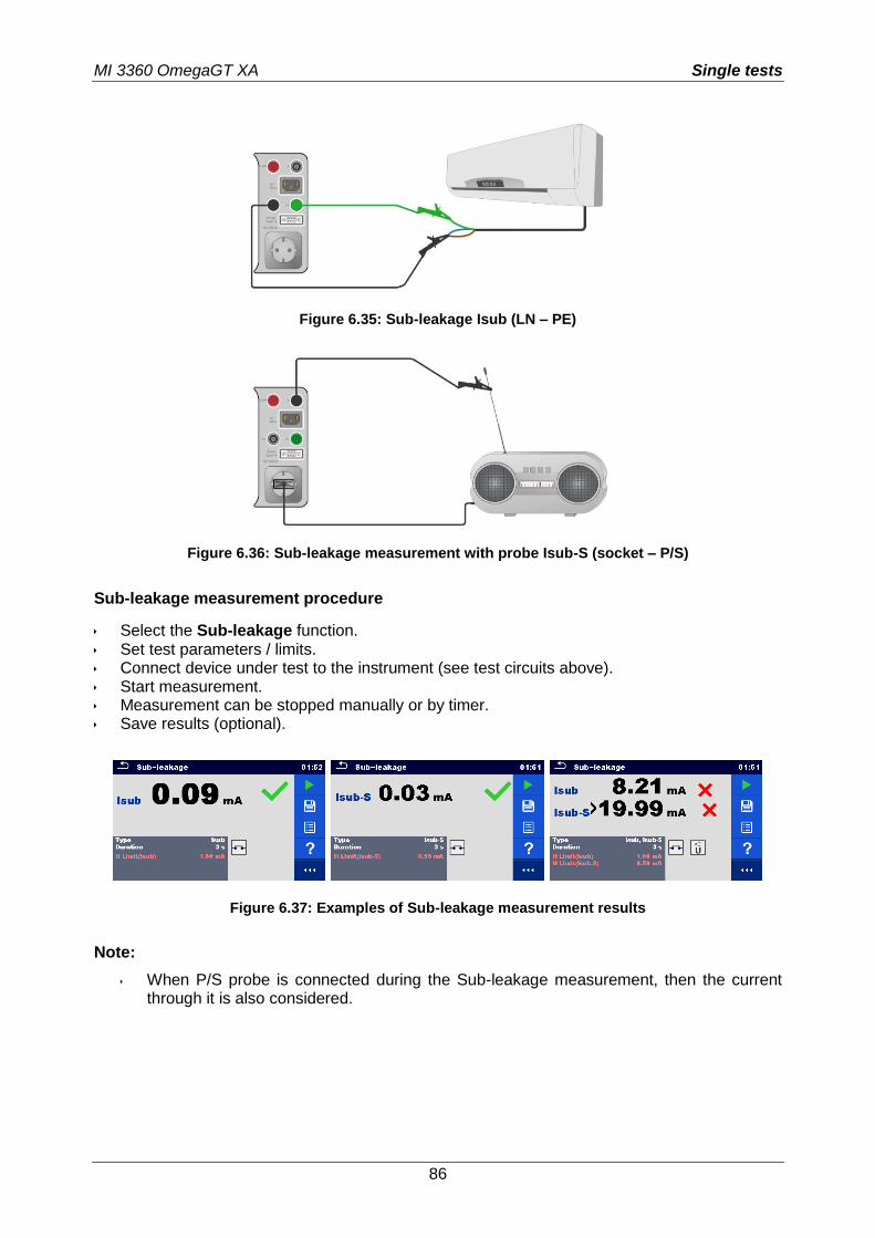
MI 3360 OmegaGT XA Single tests
86
Figure 6.35: Sub-leakage Isub (LN – PE)
Figure 6.36: Sub-leakage measurement with probe Isub-S (socket – P/S)
Sub-leakage measurement procedure
Select the Sub-leakage function. Set test parameters / limits. Connect device under test to the instrument (see test circuits above). Start measurement. Measurement can be stopped manually or by timer. Save results (optional).
Figure 6.37: Examples of Sub-leakage measurement results
Note:
When P/S probe is connected during the Sub-leakage measurement, then the current through it is also considered.
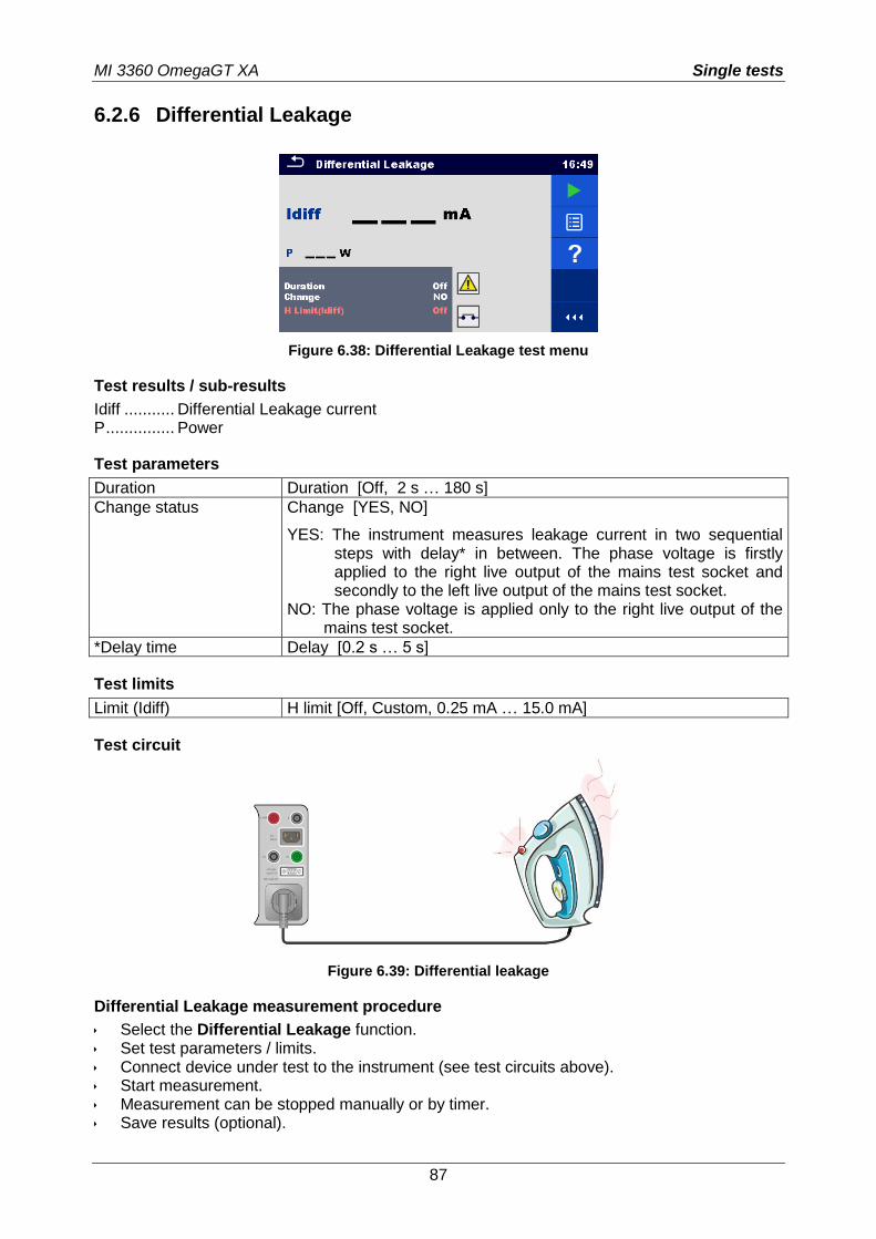
MI 3360 OmegaGT XA Single tests
87
6.2.6 Differential Leakage
Figure 6.38: Differential Leakage test menu
Test results / sub-results
Idiff ........... Differential Leakage current P ............... Power
Test parameters
Duration Duration [Off, 2 s … 180 s]
Change status Change [YES, NO]
YES: The instrument measures leakage current in two sequential steps with delay* in between. The phase voltage is firstly applied to the right live output of the mains test socket and secondly to the left live output of the mains test socket.
NO: The phase voltage is applied only to the right live output of the mains test socket.
*Delay time Delay [0.2 s … 5 s]
Test limits
Limit (Idiff) H limit [Off, Custom, 0.25 mA … 15.0 mA]
Test circuit
Figure 6.39: Differential leakage
Differential Leakage measurement procedure
Select the Differential Leakage function. Set test parameters / limits. Connect device under test to the instrument (see test circuits above). Start measurement. Measurement can be stopped manually or by timer. Save results (optional).
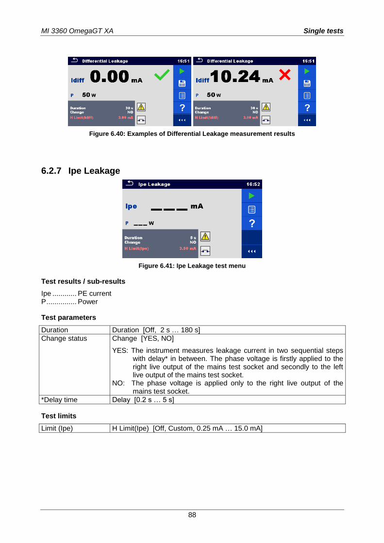
MI 3360 OmegaGT XA Single tests
88
Figure 6.40: Examples of Differential Leakage measurement results
6.2.7 Ipe Leakage
Figure 6.41: Ipe Leakage test menu
Test results / sub-results
Ipe ............ PE current P ............... Power
Test parameters
Duration Duration [Off, 2 s … 180 s]
Change status Change [YES, NO]
YES: The instrument measures leakage current in two sequential steps with delay* in between. The phase voltage is firstly applied to the right live output of the mains test socket and secondly to the left live output of the mains test socket.
NO: The phase voltage is applied only to the right live output of the mains test socket.
*Delay time Delay [0.2 s … 5 s]
Test limits
Limit (Ipe) H Limit(Ipe) [Off, Custom, 0.25 mA … 15.0 mA]
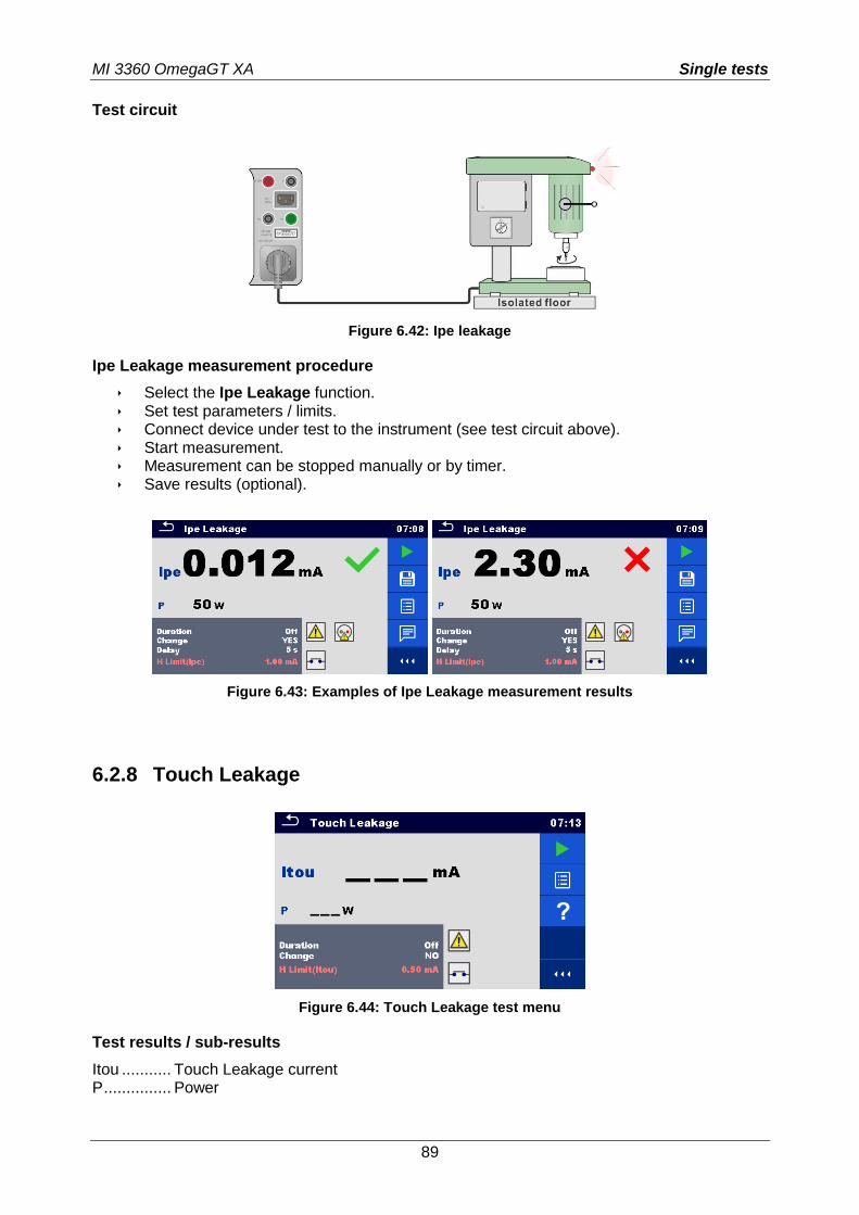
MI 3360 OmegaGT XA Single tests
89
Test circuit
Figure 6.42: Ipe leakage
Ipe Leakage measurement procedure
Select the Ipe Leakage function. Set test parameters / limits. Connect device under test to the instrument (see test circuit above). Start measurement. Measurement can be stopped manually or by timer. Save results (optional).
Figure 6.43: Examples of Ipe Leakage measurement results
6.2.8 Touch Leakage
Figure 6.44: Touch Leakage test menu
Test results / sub-results
Itou ........... Touch Leakage current P ............... Power
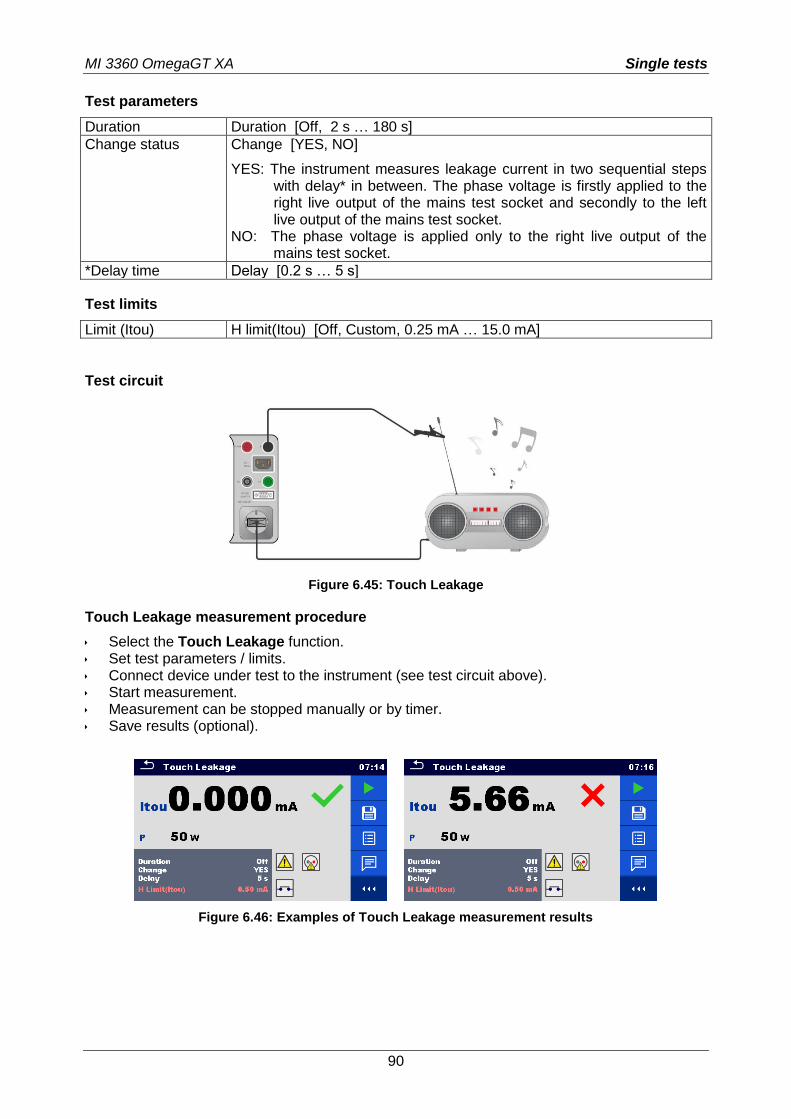
MI 3360 OmegaGT XA Single tests
90
Test parameters
Duration Duration [Off, 2 s … 180 s]
Change status Change [YES, NO]
YES: The instrument measures leakage current in two sequential steps with delay* in between. The phase voltage is firstly applied to the right live output of the mains test socket and secondly to the left live output of the mains test socket.
NO: The phase voltage is applied only to the right live output of the mains test socket.
*Delay time Delay [0.2 s … 5 s]
Test limits
Limit (Itou) H limit(Itou) [Off, Custom, 0.25 mA … 15.0 mA]
Test circuit
Figure 6.45: Touch Leakage
Touch Leakage measurement procedure
Select the Touch Leakage function. Set test parameters / limits. Connect device under test to the instrument (see test circuit above). Start measurement. Measurement can be stopped manually or by timer. Save results (optional).
Figure 6.46: Examples of Touch Leakage measurement results
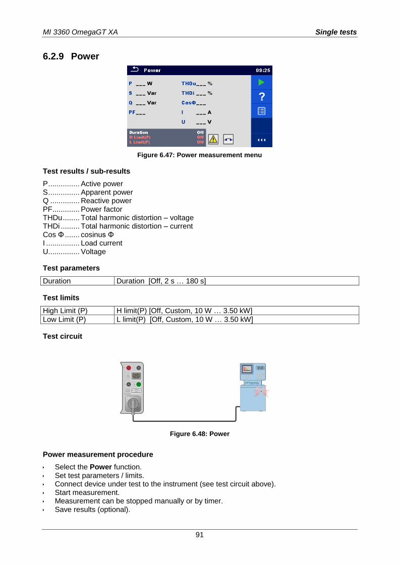
MI 3360 OmegaGT XA Single tests
91
6.2.9 Power
Figure 6.47: Power measurement menu
Test results / sub-results
P ............... Active power S ............... Apparent power Q .............. Reactive power PF ............. Power factor THDu ........ Total harmonic distortion – voltage THDi ......... Total harmonic distortion – current Cos Φ ....... cosinus Φ I ................ Load current U............... Voltage
Test parameters
Duration Duration [Off, 2 s … 180 s]
Test limits
High Limit (P) H limit(P) [Off, Custom, 10 W … 3.50 kW]
Low Limit (P) L limit(P) [Off, Custom, 10 W … 3.50 kW]
Test circuit
Figure 6.48: Power
Power measurement procedure
Select the Power function. Set test parameters / limits. Connect device under test to the instrument (see test circuit above). Start measurement. Measurement can be stopped manually or by timer. Save results (optional).
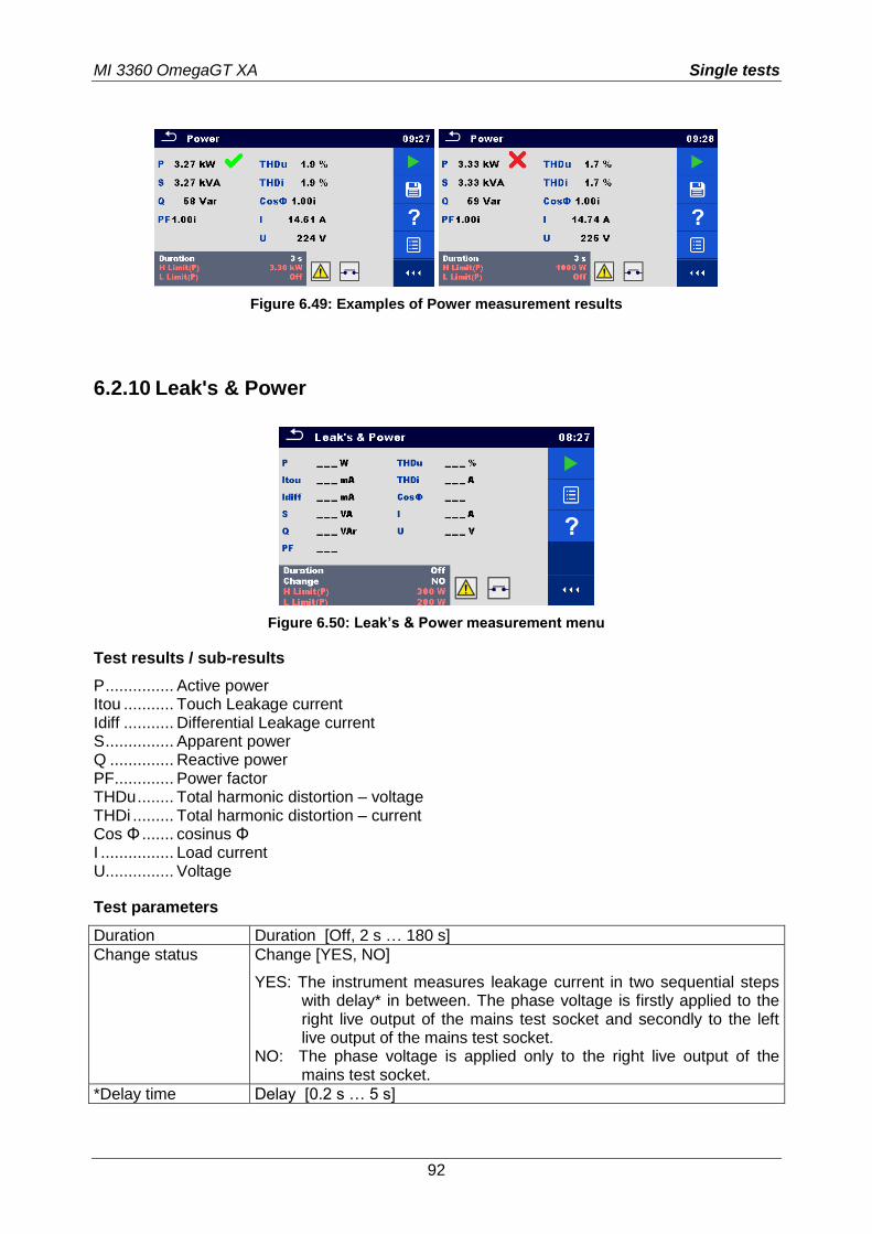
MI 3360 OmegaGT XA Single tests
92
Figure 6.49: Examples of Power measurement results
6.2.10 Leak's & Power
Figure 6.50: Leak’s & Power measurement menu
Test results / sub-results
P ............... Active power Itou ........... Touch Leakage current Idiff ........... Differential Leakage current S ............... Apparent power Q .............. Reactive power PF ............. Power factor THDu ........ Total harmonic distortion – voltage THDi ......... Total harmonic distortion – current Cos Φ ....... cosinus Φ I ................ Load current U............... Voltage
Test parameters
Duration Duration [Off, 2 s … 180 s]
Change status Change [YES, NO]
YES: The instrument measures leakage current in two sequential steps with delay* in between. The phase voltage is firstly applied to the right live output of the mains test socket and secondly to the left live output of the mains test socket.
NO: The phase voltage is applied only to the right live output of the mains test socket.
*Delay time Delay [0.2 s … 5 s]
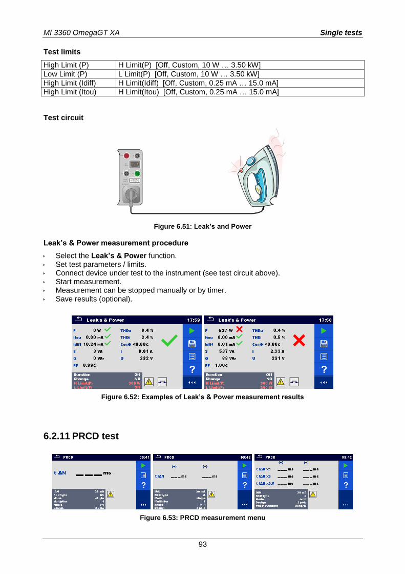
MI 3360 OmegaGT XA Single tests
93
Test limits
High Limit (P) H Limit(P) [Off, Custom, 10 W … 3.50 kW]
Low Limit (P) L Limit(P) [Off, Custom, 10 W … 3.50 kW]
High Limit (Idiff) H Limit(Idiff) [Off, Custom, 0.25 mA … 15.0 mA]
High Limit (Itou) H Limit(Itou) [Off, Custom, 0.25 mA … 15.0 mA]
Test circuit
Figure 6.51: Leak’s and Power
Leak’s & Power measurement procedure
Select the Leak’s & Power function. Set test parameters / limits. Connect device under test to the instrument (see test circuit above). Start measurement. Measurement can be stopped manually or by timer. Save results (optional).
Figure 6.52: Examples of Leak’s & Power measurement results
6.2.11 PRCD test
Figure 6.53: PRCD measurement menu
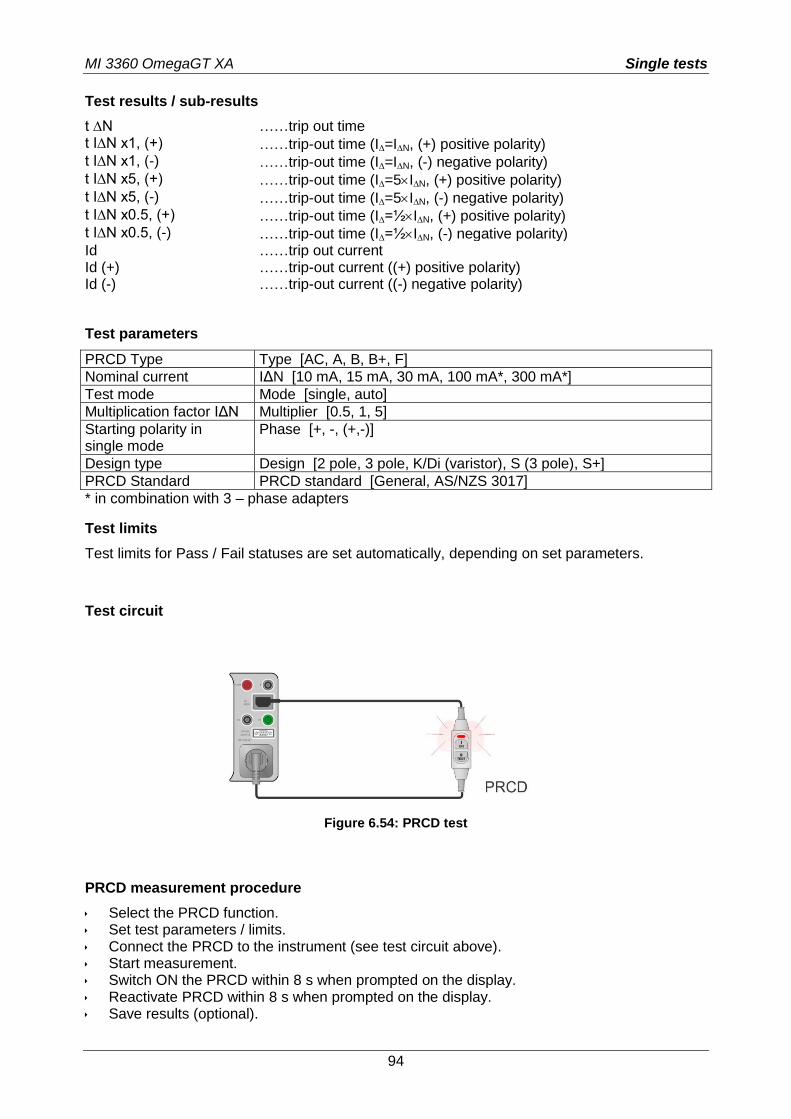
MI 3360 OmegaGT XA Single tests
94
Test results / sub-results
t ∆N ……trip out time t I∆N x1, (+) ……trip-out time (I=IN, (+) positive polarity) t I∆N x1, (-) ……trip-out time (I=IN, (-) negative polarity) t I∆N x5, (+) ……trip-out time (I=5IN, (+) positive polarity) t I∆N x5, (-) ……trip-out time (I=5IN, (-) negative polarity) t I∆N x0.5, (+) ……trip-out time (I=½IN, (+) positive polarity) t I∆N x0.5, (-) ……trip-out time (I=½IN, (-) negative polarity) Id ……trip out current Id (+) ……trip-out current ((+) positive polarity) Id (-) ……trip-out current ((-) negative polarity)
Test parameters
PRCD Type Type [AC, A, B, B+, F]
Nominal current IΔN [10 mA, 15 mA, 30 mA, 100 mA*, 300 mA*]
Test mode Mode [single, auto]
Multiplication factor IΔN Multiplier [0.5, 1, 5]
Starting polarity in single mode
Phase [+, -, (+,-)]
Design type Design [2 pole, 3 pole, K/Di (varistor), S (3 pole), S+]
PRCD Standard PRCD standard [General, AS/NZS 3017]
* in combination with 3 – phase adapters
Test limits
Test limits for Pass / Fail statuses are set automatically, depending on set parameters.
Test circuit
Figure 6.54: PRCD test
PRCD measurement procedure
Select the PRCD function. Set test parameters / limits. Connect the PRCD to the instrument (see test circuit above). Start measurement. Switch ON the PRCD within 8 s when prompted on the display. Reactivate PRCD within 8 s when prompted on the display. Save results (optional).
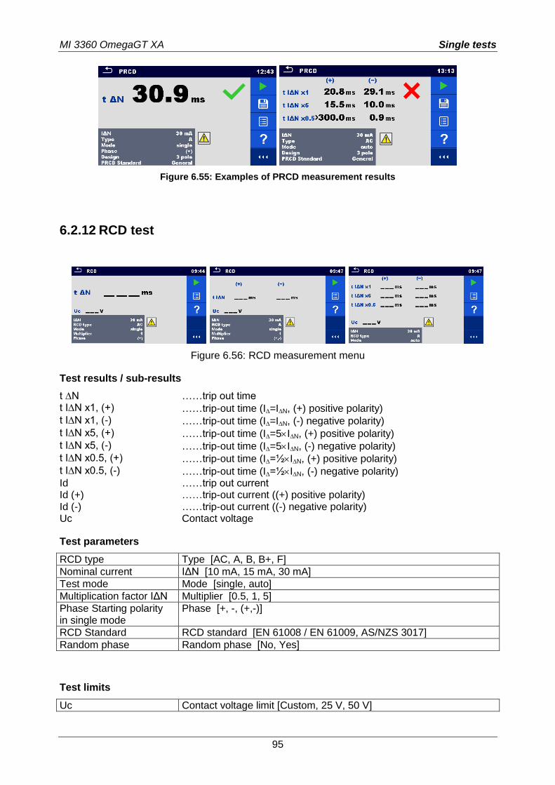
MI 3360 OmegaGT XA Single tests
95
Figure 6.55: Examples of PRCD measurement results
6.2.12 RCD test
Figure 6.56: RCD measurement menu
Test results / sub-results
t ∆N ……trip out time t I∆N x1, (+) ……trip-out time (I=IN, (+) positive polarity) t I∆N x1, (-) ……trip-out time (I=IN, (-) negative polarity) t I∆N x5, (+) ……trip-out time (I=5IN, (+) positive polarity) t I∆N x5, (-) ……trip-out time (I=5IN, (-) negative polarity) t I∆N x0.5, (+) ……trip-out time (I=½IN, (+) positive polarity) t I∆N x0.5, (-) ……trip-out time (I=½IN, (-) negative polarity) Id ……trip out current Id (+) ……trip-out current ((+) positive polarity) Id (-) ……trip-out current ((-) negative polarity) Uc Contact voltage
Test parameters
RCD type Type [AC, A, B, B+, F]
Nominal current IΔN [10 mA, 15 mA, 30 mA]
Test mode Mode [single, auto]
Multiplication factor IΔN Multiplier [0.5, 1, 5]
Phase Starting polarity in single mode
Phase [+, -, (+,-)]
RCD Standard RCD standard [EN 61008 / EN 61009, AS/NZS 3017]
Random phase Random phase [No, Yes]
Test limits
Uc Contact voltage limit [Custom, 25 V, 50 V]
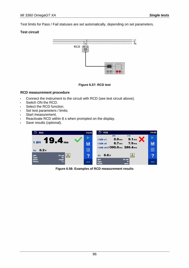
MI 3360 OmegaGT XA Single tests
96
Test limits for Pass / Fail statuses are set automatically, depending on set parameters.
Test circuit
Figure 6.57: RCD test
RCD measurement procedure
Connect the instrument to the circuit with RCD (see test circuit above). Switch ON the RCD. Select the RCD function. Set test parameters / limits. Start measurement. Reactivate RCD within 8 s when prompted on the display. Save results (optional).
Figure 6.58: Examples of RCD measurement results
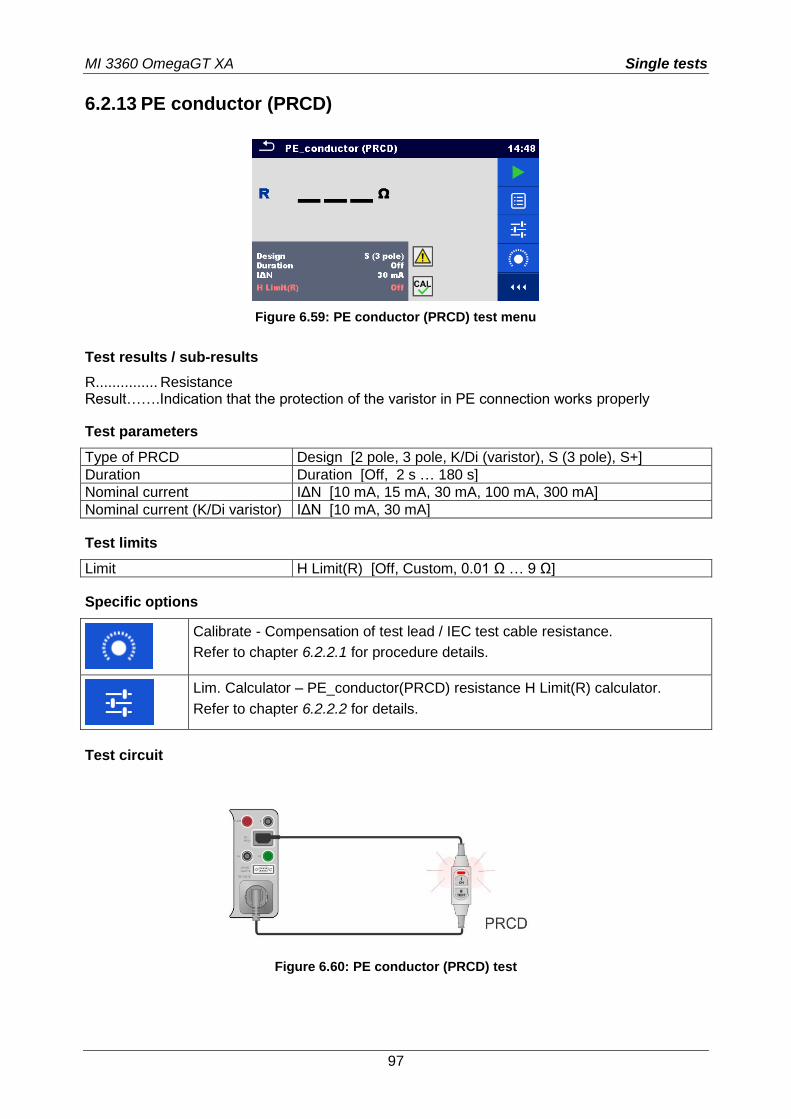
MI 3360 OmegaGT XA Single tests
97
6.2.13 PE conductor (PRCD)
Figure 6.59: PE conductor (PRCD) test menu
Test results / sub-results
R............... Resistance Result…….Indication that the protection of the varistor in PE connection works properly
Test parameters
Type of PRCD Design [2 pole, 3 pole, K/Di (varistor), S (3 pole), S+]
Duration Duration [Off, 2 s … 180 s]
Nominal current IΔN [10 mA, 15 mA, 30 mA, 100 mA, 300 mA]
Nominal current (K/Di varistor) IΔN [10 mA, 30 mA]
Test limits
Limit H Limit(R) [Off, Custom, 0.01 Ω … 9 Ω]
Specific options
Calibrate - Compensation of test lead / IEC test cable resistance.
Refer to chapter 6.2.2.1 for procedure details.
Lim. Calculator – PE_conductor(PRCD) resistance H Limit(R) calculator.
Refer to chapter 6.2.2.2 for details.
Test circuit
Figure 6.60: PE conductor (PRCD) test
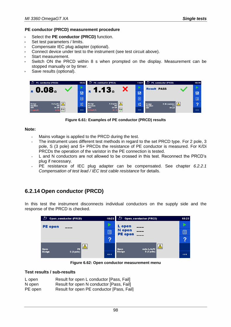
MI 3360 OmegaGT XA Single tests
98
PE conductor (PRCD) measurement procedure
Select the PE conductor (PRCD) function. Set test parameters / limits. Compensate IEC plug adapter (optional). Connect device under test to the instrument (see test circuit above). Start measurement. Switch ON the PRCD within 8 s when prompted on the display. Measurement can be
stopped manually or by timer. Save results (optional).
Figure 6.61: Examples of PE conductor (PRCD) results
Note:
Mains voltage is applied to the PRCD during the test. The instrument uses different test methods in regard to the set PRCD type. For 2 pole, 3
pole, S (3 pole) and S+ PRCDs the resistance of PE conductor is measured. For K/Di PRCDs the operation of the varistor in the PE connection is tested.
L and N conductors are not allowed to be crossed in this test. Reconnect the PRCD’s plug if necessary.
PE resistance of IEC plug adapter can be compensated. See chapter 6.2.2.1 Compensation of test lead / IEC test cable resistance for details.
6.2.14 Open conductor (PRCD)
In this test the instrument disconnects individual conductors on the supply side and the response of the PRCD is checked.
Figure 6.62: Open conductor measurement menu
Test results / sub-results
L open Result for open L conductor [Pass, Fail] N open Result for open N conductor [Pass, Fail] PE open Result for open PE conductor [Pass, Fail]
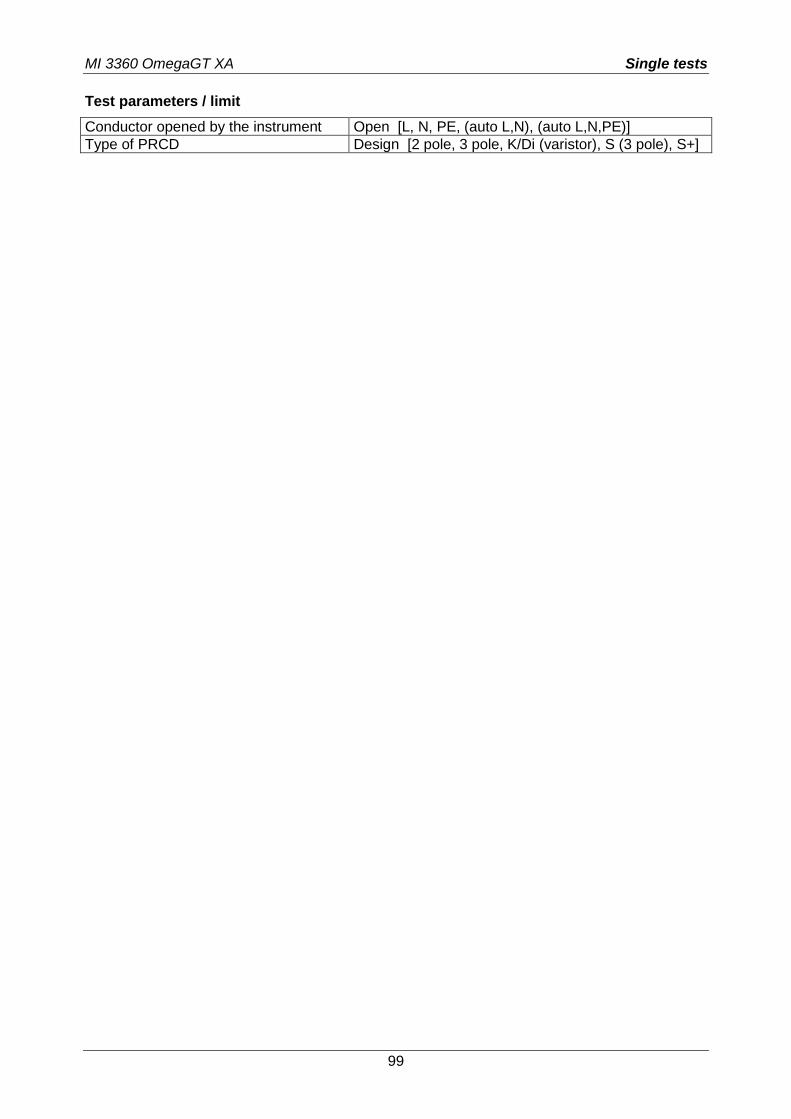
MI 3360 OmegaGT XA Single tests
99
Test parameters / limit
Conductor opened by the instrument Open [L, N, PE, (auto L,N), (auto L,N,PE)]
Type of PRCD Design [2 pole, 3 pole, K/Di (varistor), S (3 pole), S+]
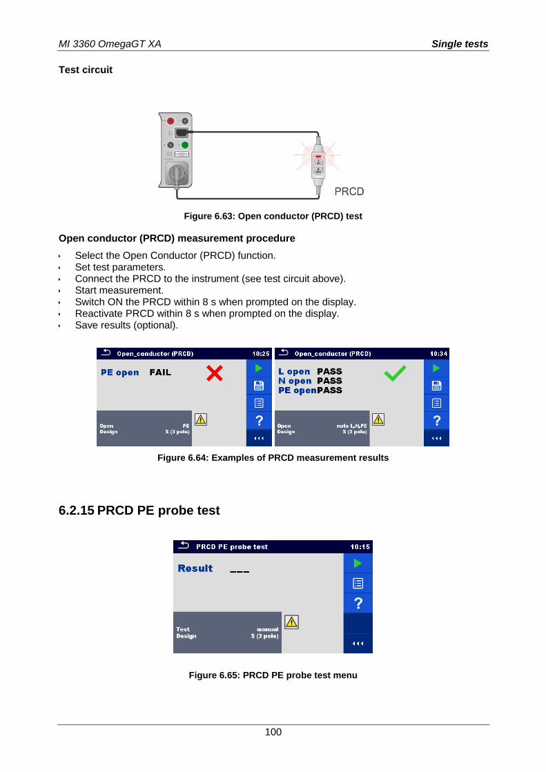
MI 3360 OmegaGT XA Single tests
100
Test circuit
Figure 6.63: Open conductor (PRCD) test
Open conductor (PRCD) measurement procedure
Select the Open Conductor (PRCD) function. Set test parameters. Connect the PRCD to the instrument (see test circuit above). Start measurement. Switch ON the PRCD within 8 s when prompted on the display. Reactivate PRCD within 8 s when prompted on the display. Save results (optional).
Figure 6.64: Examples of PRCD measurement results
6.2.15 PRCD PE probe test
Figure 6.65: PRCD PE probe test menu
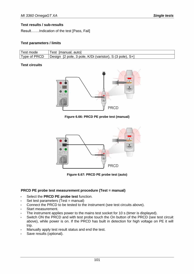
MI 3360 OmegaGT XA Single tests
101
Test results / sub-results
Result…….Indication of the test [Pass, Fail]
Test parameters / limits
Test mode Test [manual, auto]
Type of PRCD Design [2 pole, 3 pole, K/Di (varistor), S (3 pole), S+]
Test circuits
Figure 6.66: PRCD PE probe test (manual)
Figure 6.67: PRCD PE probe test (auto)
PRCD PE probe test measurement procedure (Test = manual)
Select the PRCD PE probe test function. Set test parameters (Test = manual) Connect the PRCD to be tested to the instrument (see test circuits above). Start measurement. The instrument applies power to the mains test socket for 10 s (timer is displayed). Switch ON the PRCD and with test probe touch the On button of the PRCD (see test circuit
above), while power is on. If the PRCD has built in detection for high voltage on PE it will trip.
Manually apply test result status and end the test. Save results (optional).
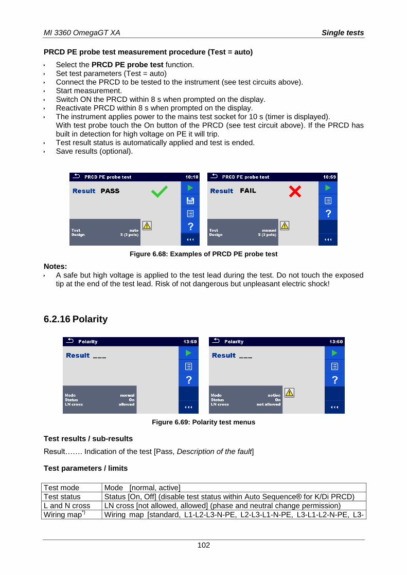
MI 3360 OmegaGT XA Single tests
102
PRCD PE probe test measurement procedure (Test = auto)
Select the PRCD PE probe test function. Set test parameters (Test = auto) Connect the PRCD to be tested to the instrument (see test circuits above). Start measurement. Switch ON the PRCD within 8 s when prompted on the display. Reactivate PRCD within 8 s when prompted on the display. The instrument applies power to the mains test socket for 10 s (timer is displayed).
With test probe touch the On button of the PRCD (see test circuit above). If the PRCD has built in detection for high voltage on PE it will trip.
Test result status is automatically applied and test is ended. Save results (optional).
Figure 6.68: Examples of PRCD PE probe test
Notes: A safe but high voltage is applied to the test lead during the test. Do not touch the exposed
tip at the end of the test lead. Risk of not dangerous but unpleasant electric shock!
6.2.16 Polarity
Figure 6.69: Polarity test menus
Test results / sub-results
Result……. Indication of the test [Pass, Description of the fault]
Test parameters / limits
Test mode Mode [normal, active]
Test status Status [On, Off] (disable test status within Auto Sequence® for K/Di PRCD)
L and N cross LN cross [not allowed, allowed] (phase and neutral change permission)
Wiring map*) Wiring map [standard, L1-L2-L3-N-PE, L2-L3-L1-N-PE, L3-L1-L2-N-PE, L3-
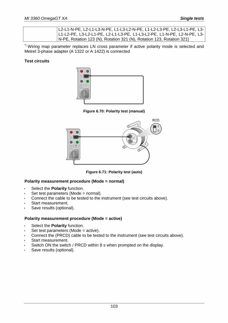
MI 3360 OmegaGT XA Single tests
103
L2-L1-N-PE, L2-L1-L3-N-PE, L1-L3-L2-N-PE, L1-L2-L3-PE, L2-L3-L1-PE, L3-L1-L2-PE, L3-L2-L1-PE, L2-L1-L3-PE, L1-L3-L2-PE, L1-N-PE, L2-N-PE, L3-N-PE, Rotation 123 (N), Rotation 321 (N), Rotation 123, Rotation 321]
*) Wiring map parameter replaces LN cross parameter if active polarity mode is selected and Metrel 3-phase adapter (A 1322 or A 1422) is connected
Test circuits
Figure 6.70: Polarity test (manual)
Figure 6.71: Polarity test (auto)
Polarity measurement procedure (Mode = normal)
Select the Polarity function. Set test parameters (Mode = normal). Connect the cable to be tested to the instrument (see test circuits above). Start measurement. Save results (optional).
Polarity measurement procedure (Mode = active)
Select the Polarity function. Set test parameters (Mode = active). Connect the (PRCD) cable to be tested to the instrument (see test circuits above). Start measurement. Switch ON the switch / PRCD within 8 s when prompted on the display. Save results (optional).
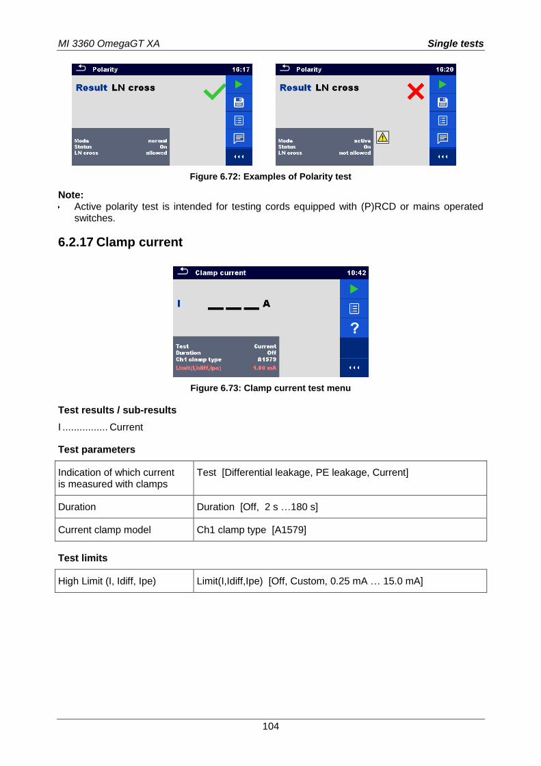
MI 3360 OmegaGT XA Single tests
104
Figure 6.72: Examples of Polarity test
Note: Active polarity test is intended for testing cords equipped with (P)RCD or mains operated
switches.
6.2.17 Clamp current
Figure 6.73: Clamp current test menu
Test results / sub-results
I ................ Current
Test parameters
Indication of which current is measured with clamps
Test [Differential leakage, PE leakage, Current]
Duration Duration [Off, 2 s …180 s]
Current clamp model Ch1 clamp type [A1579]
Test limits
High Limit (I, Idiff, Ipe) Limit(I,Idiff,Ipe) [Off, Custom, 0.25 mA … 15.0 mA]
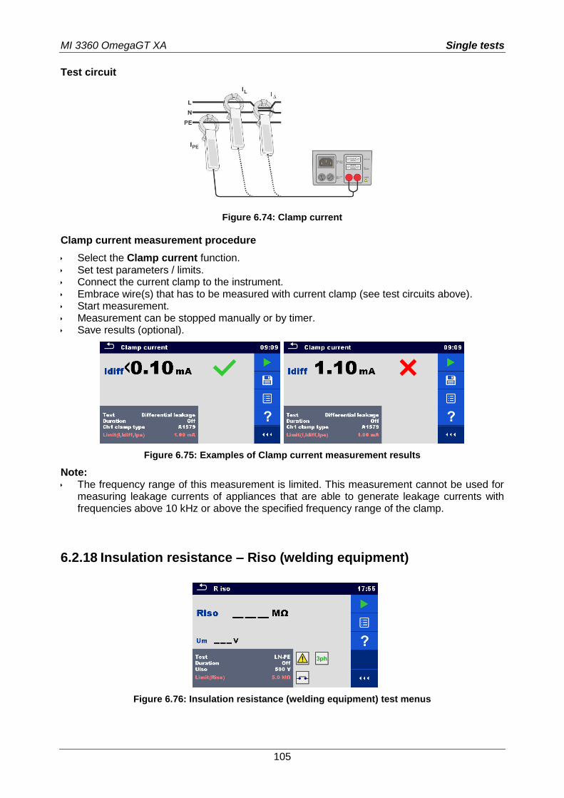
MI 3360 OmegaGT XA Single tests
105
Test circuit
Figure 6.74: Clamp current
Clamp current measurement procedure
Select the Clamp current function. Set test parameters / limits. Connect the current clamp to the instrument. Embrace wire(s) that has to be measured with current clamp (see test circuits above). Start measurement. Measurement can be stopped manually or by timer. Save results (optional).
Figure 6.75: Examples of Clamp current measurement results
Note: The frequency range of this measurement is limited. This measurement cannot be used for
measuring leakage currents of appliances that are able to generate leakage currents with frequencies above 10 kHz or above the specified frequency range of the clamp.
6.2.18 Insulation resistance – Riso (welding equipment)
Figure 6.76: Insulation resistance (welding equipment) test menus
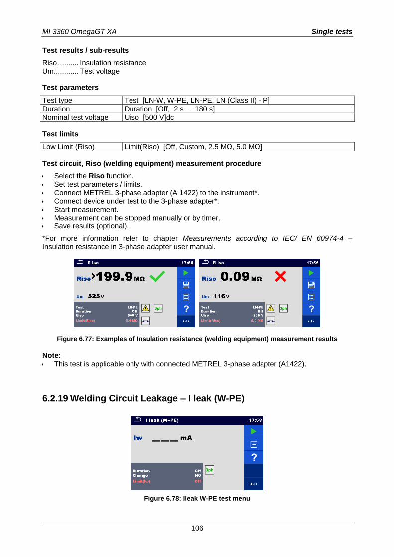
MI 3360 OmegaGT XA Single tests
106
Test results / sub-results
Riso .......... Insulation resistance Um ............ Test voltage
Test parameters
Test type Test [LN-W, W-PE, LN-PE, LN (Class II) - P]
Duration Duration [Off, 2 s … 180 s]
Nominal test voltage Uiso [500 V]dc
Test limits
Low Limit (Riso) Limit(Riso) [Off, Custom, 2.5 MΩ, 5.0 MΩ]
Test circuit, Riso (welding equipment) measurement procedure
Select the Riso function. Set test parameters / limits. Connect METREL 3-phase adapter (A 1422) to the instrument*. Connect device under test to the 3-phase adapter*. Start measurement. Measurement can be stopped manually or by timer. Save results (optional).
*For more information refer to chapter Measurements according to IEC/ EN 60974-4 – Insulation resistance in 3-phase adapter user manual.
Figure 6.77: Examples of Insulation resistance (welding equipment) measurement results
Note: This test is applicable only with connected METREL 3-phase adapter (A1422).
6.2.19 Welding Circuit Leakage – I leak (W-PE)
Figure 6.78: Ileak W-PE test menu
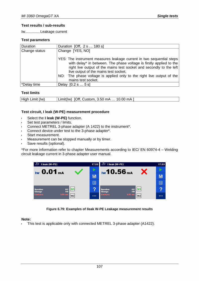
MI 3360 OmegaGT XA Single tests
107
Test results / sub-results
Iw.............. Leakage current
Test parameters
Duration Duration [Off, 2 s … 180 s]
Change status Change [YES, NO]
YES: The instrument measures leakage current in two sequential steps with delay* in between. The phase voltage is firstly applied to the right live output of the mains test socket and secondly to the left live output of the mains test socket.
NO: The phase voltage is applied only to the right live output of the mains test socket.
*Delay time Delay [0.2 s … 5 s]
Test limits
High Limit (Iw) Limit(Iw) [Off, Custom, 3.50 mA … 10.00 mA ]
Test circuit, I leak (W-PE) measurement procedure
Select the I leak (W-PE) function. Set test parameters / limits. Connect METREL 3-phase adapter (A 1422) to the instrument*. Connect device under test to the 3-phase adapter*. Start measurement. Measurement can be stopped manually or by timer. Save results (optional).
*For more information refer to chapter Measurements according to IEC/ EN 60974-4 – Welding circuit leakage current in 3-phase adapter user manual.
Figure 6.79: Examples of Ileak W-PE Leakage measurement results
Note: This test is applicable only with connected METREL 3-phase adapter (A1422).
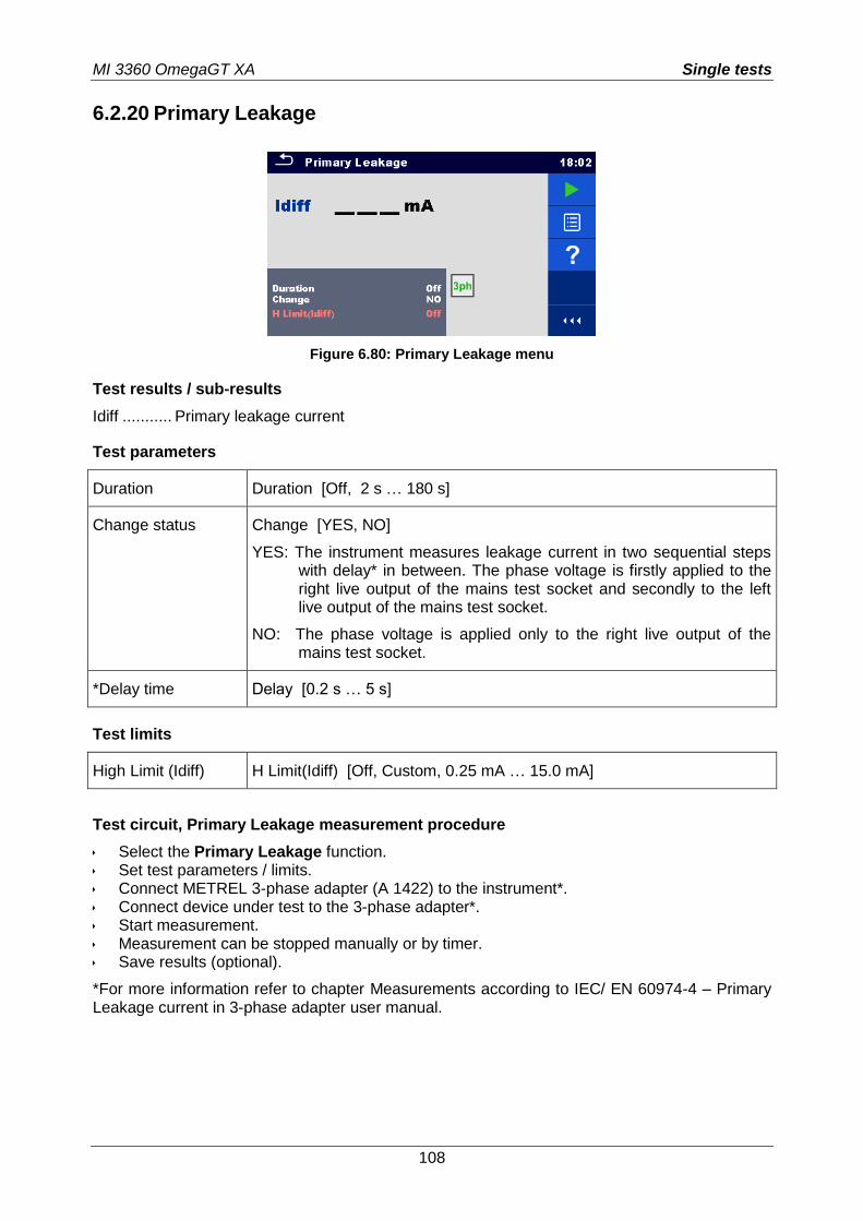
MI 3360 OmegaGT XA Single tests
108
6.2.20 Primary Leakage
Figure 6.80: Primary Leakage menu
Test results / sub-results
Idiff ........... Primary leakage current
Test parameters
Duration Duration [Off, 2 s … 180 s]
Change status Change [YES, NO]
YES: The instrument measures leakage current in two sequential steps with delay* in between. The phase voltage is firstly applied to the right live output of the mains test socket and secondly to the left live output of the mains test socket.
NO: The phase voltage is applied only to the right live output of the mains test socket.
*Delay time Delay [0.2 s … 5 s]
Test limits
High Limit (Idiff) H Limit(Idiff) [Off, Custom, 0.25 mA … 15.0 mA]
Test circuit, Primary Leakage measurement procedure
Select the Primary Leakage function. Set test parameters / limits. Connect METREL 3-phase adapter (A 1422) to the instrument*. Connect device under test to the 3-phase adapter*. Start measurement. Measurement can be stopped manually or by timer. Save results (optional).
*For more information refer to chapter Measurements according to IEC/ EN 60974-4 – Primary Leakage current in 3-phase adapter user manual.
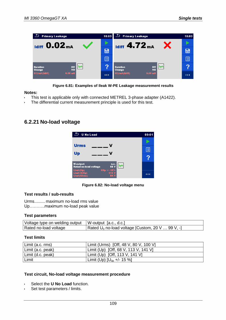
MI 3360 OmegaGT XA Single tests
109
Figure 6.81: Examples of Ileak W-PE Leakage measurement results
Notes: This test is applicable only with connected METREL 3-phase adapter (A1422). The differential current measurement principle is used for this test.
6.2.21 No-load voltage
Figure 6.82: No-load voltage menu
Test results / sub-results
Urms ......... maximum no-load rms value Up………..maximum no-load peak value
Test parameters
Voltage type on welding output W-output [a.c., d.c.]
Rated no-load voltage Rated U0 no-load voltage [Custom, 20 V … 99 V, -]
Test limits
Limit (a.c. rms) Limit (Urms) [Off, 48 V, 80 V, 100 V]
Limit (a.c. peak) Limit (Up) [Off, 68 V, 113 V, 141 V]
Limit (d.c. peak) Limit (Up) [Off, 113 V, 141 V]
Limit Limit (Up) [U0p +/- 15 %]
Test circuit, No-load voltage measurement procedure Select the U No Load function. Set test parameters / limits.
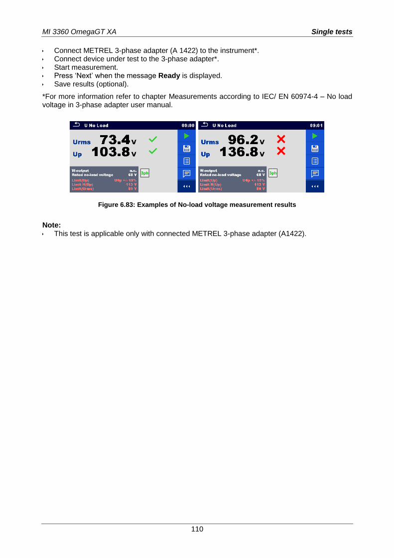
MI 3360 OmegaGT XA Single tests
110
Connect METREL 3-phase adapter (A 1422) to the instrument*. Connect device under test to the 3-phase adapter*. Start measurement. Press ‘Next’ when the message Ready is displayed. Save results (optional).
*For more information refer to chapter Measurements according to IEC/ EN 60974-4 – No load voltage in 3-phase adapter user manual.
Figure 6.83: Examples of No-load voltage measurement results
Note: This test is applicable only with connected METREL 3-phase adapter (A1422).
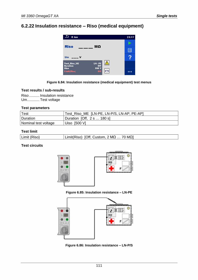
MI 3360 OmegaGT XA Single tests
111
6.2.22 Insulation resistance – Riso (medical equipment)
Figure 6.84: Insulation resistance (medical equipment) test menus
Test results / sub-results
Riso .......... Insulation resistance Um ............ Test voltage
Test parameters
Test Test_Riso_ME [LN-PE, LN-P/S, LN-AP, PE-AP]
Duration Duration [Off, 2 s … 180 s]
Nominal test voltage Uiso [500 V]
Test limit
Limit (Riso) Limit(Riso) [Off, Custom, 2 MΩ … 70 MΩ]
Test circuits
Figure 6.85: Insulation resistance – LN-PE
Figure 6.86: Insulation resistance – LN-P/S
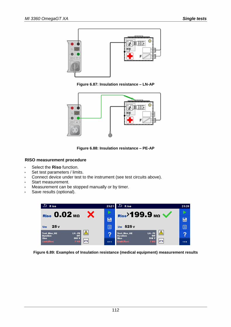
MI 3360 OmegaGT XA Single tests
112
Figure 6.87: Insulation resistance – LN-AP
Figure 6.88: Insulation resistance – PE-AP
RISO measurement procedure
Select the Riso function. Set test parameters / limits. Connect device under test to the instrument (see test circuits above). Start measurement. Measurement can be stopped manually or by timer. Save results (optional).
Figure 6.89: Examples of Insulation resistance (medical equipment) measurement results
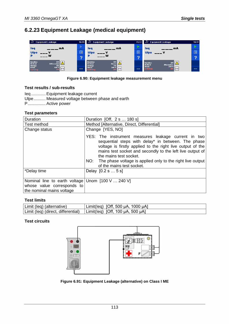
MI 3360 OmegaGT XA Single tests
113
6.2.23 Equipment Leakage (medical equipment)
Figure 6.90: Equipment leakage measurement menu
Test results / sub-results
Ieq ............ Equipment leakage current Ulpe .......... Measured voltage between phase and earth P ............... Active power
Test parameters
Duration Duration [Off, 2 s … 180 s]
Test method Method [Alternative, Direct, Differential]
Change status Change [YES, NO]
YES: The instrument measures leakage current in two sequential steps with delay* in between. The phase voltage is firstly applied to the right live output of the mains test socket and secondly to the left live output of the mains test socket.
NO: The phase voltage is applied only to the right live output of the mains test socket.
*Delay time Delay [0.2 s … 5 s]
Nominal line to earth voltage whose value corresponds to the nominal mains voltage
Unom [100 V … 240 V]
Test limits
Limit (Ieq) (alternative) Limit(Ieq) [Off, 500 µA, 1000 µA]
Limit (Ieq) (direct, differential) Limit(Ieq) [Off, 100 µA, 500 µA]
Test circuits
Figure 6.91: Equipment Leakage (alternative) on Class I ME
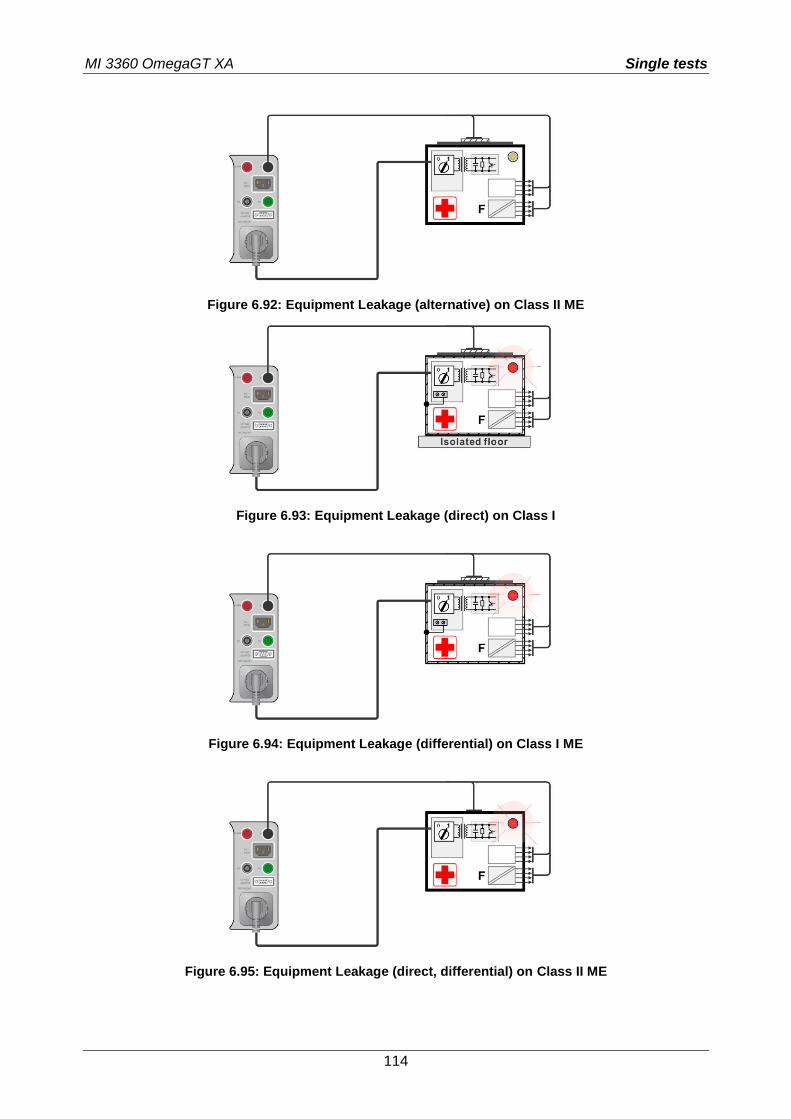
MI 3360 OmegaGT XA Single tests
114
Figure 6.92: Equipment Leakage (alternative) on Class II ME
Figure 6.93: Equipment Leakage (direct) on Class I
Figure 6.94: Equipment Leakage (differential) on Class I ME
Figure 6.95: Equipment Leakage (direct, differential) on Class II ME
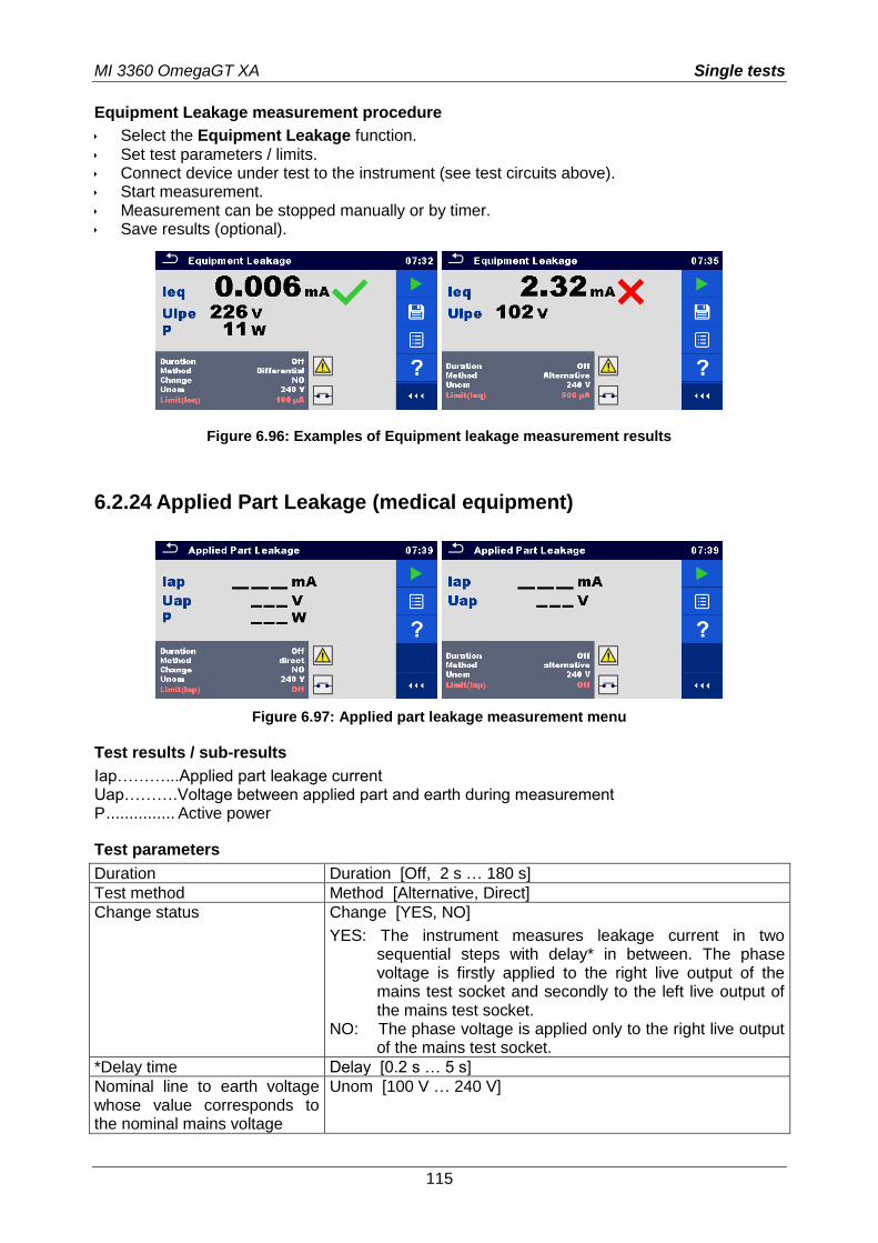
MI 3360 OmegaGT XA Single tests
115
Equipment Leakage measurement procedure
Select the Equipment Leakage function. Set test parameters / limits. Connect device under test to the instrument (see test circuits above). Start measurement. Measurement can be stopped manually or by timer. Save results (optional).
Figure 6.96: Examples of Equipment leakage measurement results
6.2.24 Applied Part Leakage (medical equipment)
Figure 6.97: Applied part leakage measurement menu
Test results / sub-results
Iap………...Applied part leakage current Uap……….Voltage between applied part and earth during measurement P ............... Active power
Test parameters
Duration Duration [Off, 2 s … 180 s]
Test method Method [Alternative, Direct]
Change status Change [YES, NO]
YES: The instrument measures leakage current in two sequential steps with delay* in between. The phase voltage is firstly applied to the right live output of the mains test socket and secondly to the left live output of the mains test socket.
NO: The phase voltage is applied only to the right live output of the mains test socket.
*Delay time Delay [0.2 s … 5 s]
Nominal line to earth voltage whose value corresponds to the nominal mains voltage
Unom [100 V … 240 V]
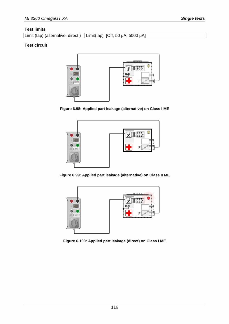
MI 3360 OmegaGT XA Single tests
116
Test limits
Limit (Iap) (alternative, direct ) Limit(Iap) [Off, 50 µA, 5000 µA]
Test circuit
Figure 6.98: Applied part leakage (alternative) on Class I ME
Figure 6.99: Applied part leakage (alternative) on Class II ME
Figure 6.100: Applied part leakage (direct) on Class I ME
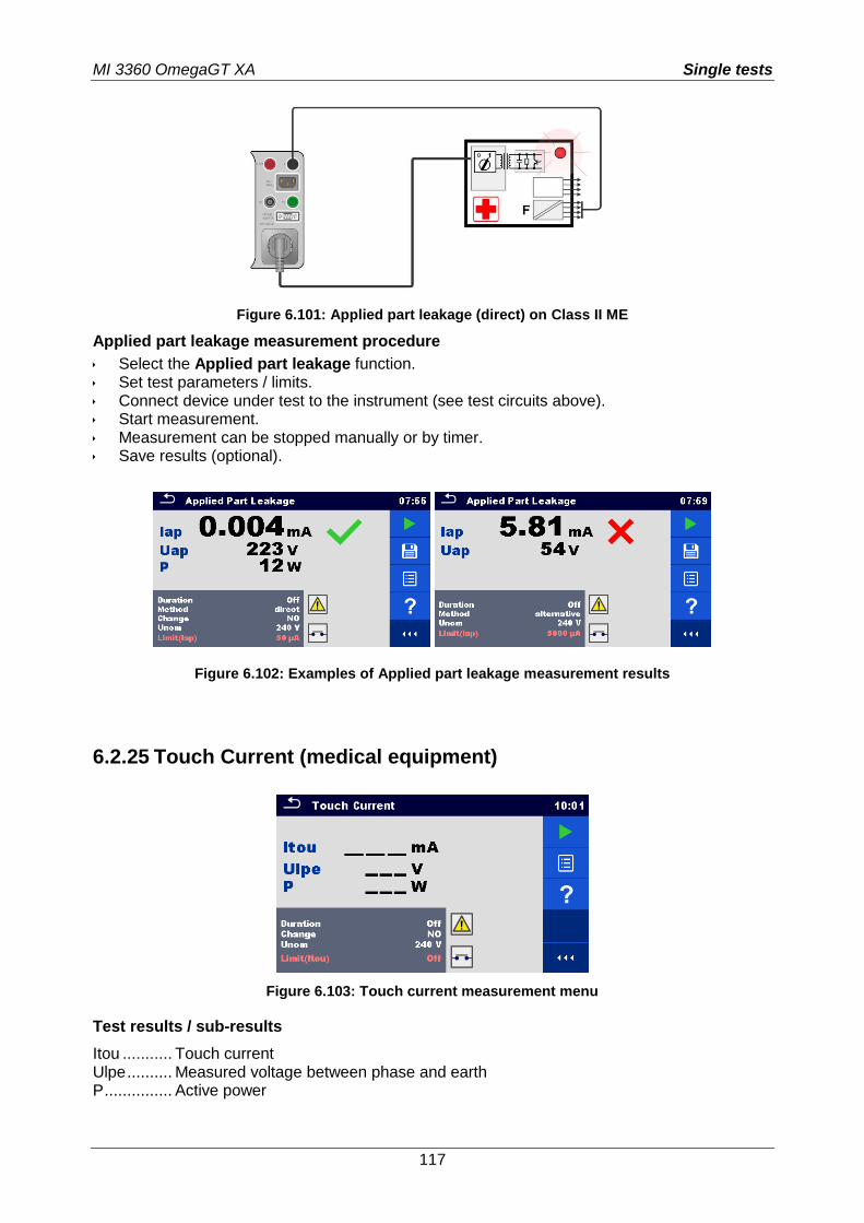
MI 3360 OmegaGT XA Single tests
117
Figure 6.101: Applied part leakage (direct) on Class II ME
Applied part leakage measurement procedure
Select the Applied part leakage function. Set test parameters / limits. Connect device under test to the instrument (see test circuits above). Start measurement. Measurement can be stopped manually or by timer. Save results (optional).
Figure 6.102: Examples of Applied part leakage measurement results
6.2.25 Touch Current (medical equipment)
Figure 6.103: Touch current measurement menu
Test results / sub-results
Itou ........... Touch current Ulpe .......... Measured voltage between phase and earth P ............... Active power
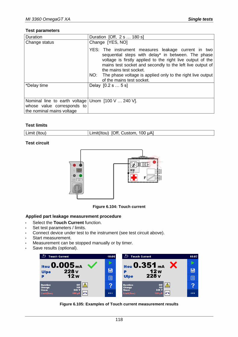
MI 3360 OmegaGT XA Single tests
118
Test parameters
Duration Duration [Off, 2 s … 180 s]
Change status Change [YES, NO]
YES: The instrument measures leakage current in two sequential steps with delay* in between. The phase voltage is firstly applied to the right live output of the mains test socket and secondly to the left live output of the mains test socket.
NO: The phase voltage is applied only to the right live output of the mains test socket.
*Delay time Delay [0.2 s … 5 s]
Nominal line to earth voltage whose value corresponds to the nominal mains voltage
Unom [100 V … 240 V].
Test limits
Limit (Itou) Limit(Itou) [Off, Custom, 100 µA]
Test circuit
Figure 6.104: Touch current
Applied part leakage measurement procedure
Select the Touch Current function. Set test parameters / limits. Connect device under test to the instrument (see test circuit above). Start measurement. Measurement can be stopped manually or by timer. Save results (optional).
Figure 6.105: Examples of Touch current measurement results
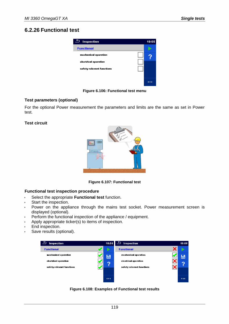
MI 3360 OmegaGT XA Single tests
119
6.2.26 Functional test
Figure 6.106: Functional test menu
Test parameters (optional)
For the optional Power measurement the parameters and limits are the same as set in Power test.
Test circuit
Figure 6.107: Functional test
Functional test inspection procedure
Select the appropriate Functional test function. Start the inspection. Power on the appliance through the mains test socket. Power measurement screen is
displayed (optional). Perform the functional inspection of the appliance / equipment. Apply appropriate ticker(s) to items of inspection. End inspection. Save results (optional).
Figure 6.108: Examples of Functional test results
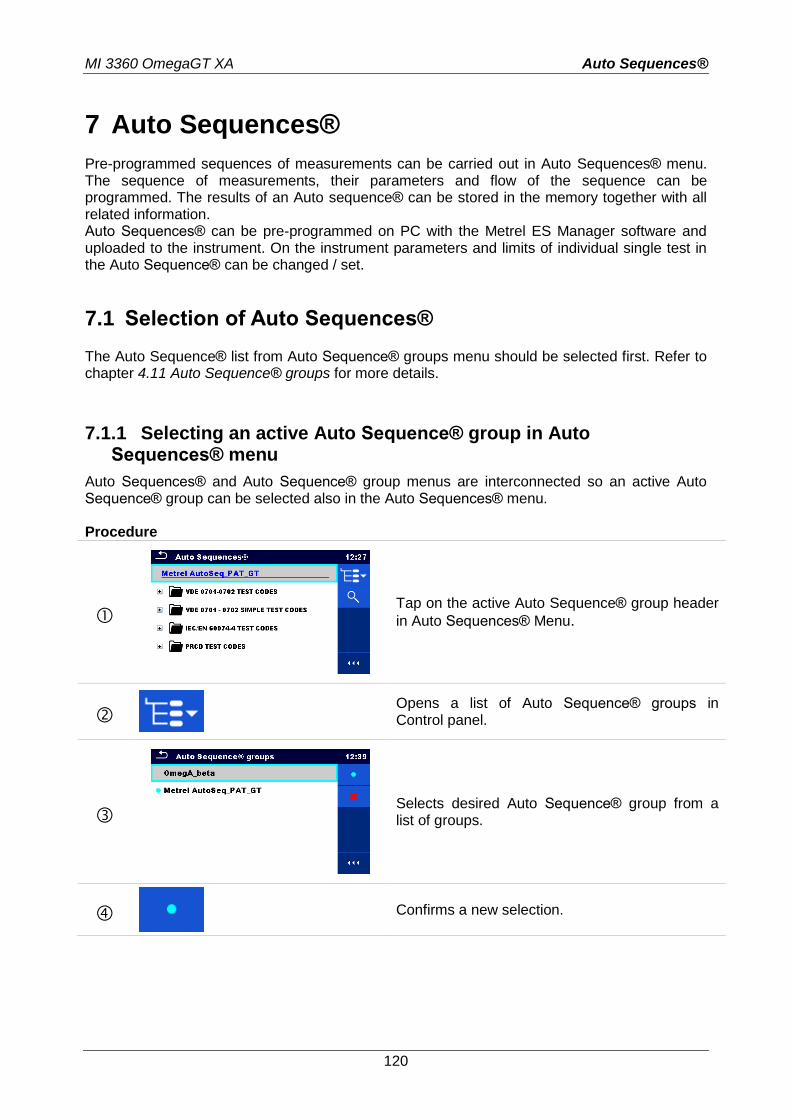
MI 3360 OmegaGT XA Auto Sequences®
120
7 Auto Sequences®
Pre-programmed sequences of measurements can be carried out in Auto Sequences® menu. The sequence of measurements, their parameters and flow of the sequence can be programmed. The results of an Auto sequence® can be stored in the memory together with all related information. Auto Sequences® can be pre-programmed on PC with the Metrel ES Manager software and uploaded to the instrument. On the instrument parameters and limits of individual single test in the Auto Sequence® can be changed / set.
7.1 Selection of Auto Sequences®
The Auto Sequence® list from Auto Sequence® groups menu should be selected first. Refer to chapter 4.11 Auto Sequence® groups for more details.
7.1.1 Selecting an active Auto Sequence® group in Auto Sequences® menu
Auto Sequences® and Auto Sequence® group menus are interconnected so an active Auto Sequence® group can be selected also in the Auto Sequences® menu. Procedure
Tap on the active Auto Sequence® group header
in Auto Sequences® Menu.
Opens a list of Auto Sequence® groups in Control panel.
Selects desired Auto Sequence® group from a list of groups.
Confirms a new selection.
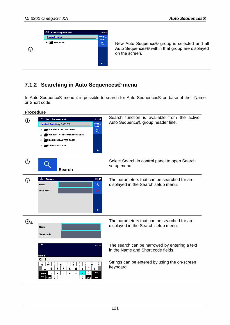
MI 3360 OmegaGT XA Auto Sequences®
121
New Auto Sequence® group is selected and all Auto Sequences® within that group are displayed on the screen.
7.1.2 Searching in Auto Sequences® menu
In Auto Sequence® menu it is possible to search for Auto Sequences® on base of their Name or Short code. Procedure
Search function is available from the active Auto Sequence® group header line.
Search
Select Search in control panel to open Search setup menu.
The parameters that can be searched for are displayed in the Search setup menu.
a
The parameters that can be searched for are displayed in the Search setup menu. The search can be narrowed by entering a text in the Name and Short code fields.
Strings can be entered by using the on-screen keyboard.
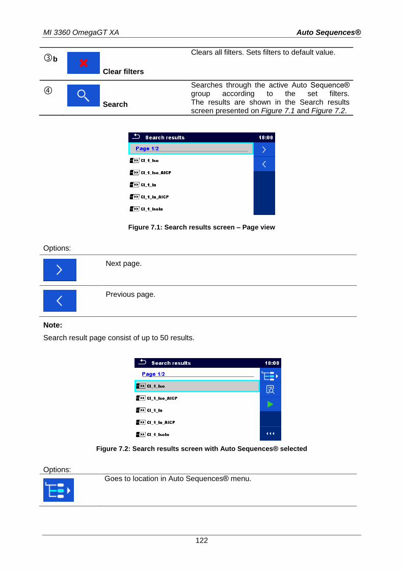
MI 3360 OmegaGT XA Auto Sequences®
122
b Clear filters
Clears all filters. Sets filters to default value.
Search
Searches through the active Auto Sequence® group according to the set filters. The results are shown in the Search results screen presented on Figure 7.1 and Figure 7.2.
Figure 7.1: Search results screen – Page view
Options:
Next page.
Previous page.
Note:
Search result page consist of up to 50 results.
Figure 7.2: Search results screen with Auto Sequences® selected
Options:
Goes to location in Auto Sequences® menu.

MI 3360 OmegaGT XA Auto Sequences®
123
Goes to Auto Sequence® view menu.
Starts the selected Auto Sequence®.
7.1.3 Organization of Auto Sequences® in Auto Sequences® menu
The Auto Sequences® to be carried out can be selected from the Main Auto Sequences® menu. This menu can be organized in a structural manner with folders, sub-folders and Auto Sequences®. Auto Sequence® in the structure can be the original Auto Sequence® or a shortcut to the original Auto Sequence®. Auto Sequences® marked as shortcuts and the original auto Sequences® are coupled. Changing of parameters or limits in any of the coupled Auto Sequences® will influence on the original Auto Sequence® and all its shortcuts.
Figure 7.3: Examples of organized Auto Sequences® in main Auto Sequences® menu
Options:
The original Auto Sequence®.
A shortcut to the original Auto Sequence®.
Starts the selected Auto Sequence®.
The instrument immediately starts the Auto sequence®.
Enters menu for more detail view of selected Auto sequence®.
This option should also be used if the parameters / limits of the selected Auto Sequence® have to be changed. Refer to chapter 7.2.1 Auto Sequence® view menu for more information.
Enters Auto Sequence® Configurator menu.
See chapter 7.2.1.3 Auto Sequence® Configurator menu for details.
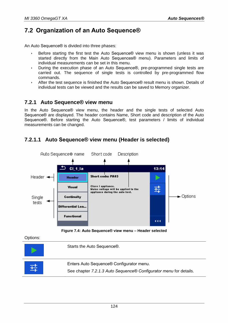
MI 3360 OmegaGT XA Auto Sequences®
124
7.2 Organization of an Auto Sequence®
An Auto Sequence® is divided into three phases:
Before starting the first test the Auto Sequence® view menu is shown (unless it was started directly from the Main Auto Sequences® menu). Parameters and limits of individual measurements can be set in this menu.
During the execution phase of an Auto Sequence®, pre-programmed single tests are carried out. The sequence of single tests is controlled by pre-programmed flow commands.
After the test sequence is finished the Auto Sequence® result menu is shown. Details of individual tests can be viewed and the results can be saved to Memory organizer.
7.2.1 Auto Sequence® view menu
In the Auto Sequence® view menu, the header and the single tests of selected Auto Sequence® are displayed. The header contains Name, Short code and description of the Auto Sequence®. Before starting the Auto Sequence®, test parameters / limits of individual measurements can be changed.
7.2.1.1 Auto Sequence® view menu (Header is selected)
Figure 7.4: Auto Sequence® view menu – Header selected
Options:
Starts the Auto Sequence®.
Enters Auto Sequence® Configurator menu.
See chapter 7.2.1.3 Auto Sequence® Configurator menu for details.

MI 3360 OmegaGT XA Auto Sequences®
125
7.2.1.2 Auto Sequence® view menu (measurement is selected)
Figure 7.5: Auto Sequence® view menu – measurement selected
Options:
Selects single test.
on
Opens menu for changing parameters and limits of selected measurements.
Refer to chapter 6.1.1.2 Setting parameters and limits of single tests for more information how to change measurement parameters and limits.
Starts the Auto Sequence®.
Opens help screens. Refer to chapter 6.1.3 Help screens for more information.
Selects Multiple points.
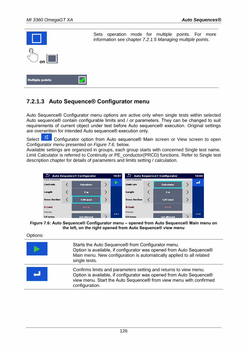
MI 3360 OmegaGT XA Auto Sequences®
126
on
Sets operation mode for multiple points. For more information see chapter 7.2.1.5 Managing multiple points.
7.2.1.3 Auto Sequence® Configurator menu
Auto Sequence® Configurator menu options are active only when single tests within selected Auto sequence® contain configurable limits and / or parameters. They can be changed to suit requirements of current object under test before Auto sequence® execution. Original settings are overwritten for intended Auto sequence® execution only.
Select Configurator option from Auto sequence® Main screen or View screen to open Configurator menu presented on Figure 7.6. below. Available settings are organized in groups, each group starts with concerned Single test name. Limit Calculator is referred to Continuity or PE_conductor(PRCD) functions. Refer to Single test description chapter for details of parameters and limits setting / calculation.
Figure 7.6: Auto Sequence® Configurator menu – opened from Auto Sequence® Main menu on the left, on the right opened from Auto Sequence® view menu
Options:
Starts the Auto Sequence® from Configurator menu. Option is available, if configurator was opened from Auto Sequence® Main menu. New configuration is automatically applied to all related single tests.
Confirms limits and parameters setting and returns to view menu. Option is available, if configurator was opened from Auto Sequence® view menu. Start the Auto Sequence® from view menu with confirmed configuration.
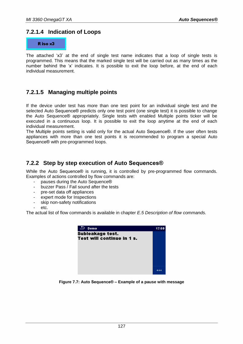
MI 3360 OmegaGT XA Auto Sequences®
127
7.2.1.4 Indication of Loops
The attached ‘x3’ at the end of single test name indicates that a loop of single tests is programmed. This means that the marked single test will be carried out as many times as the number behind the ‘x’ indicates. It is possible to exit the loop before, at the end of each individual measurement.
7.2.1.5 Managing multiple points
If the device under test has more than one test point for an individual single test and the selected Auto Sequence® predicts only one test point (one single test) it is possible to change the Auto Sequence® appropriately. Single tests with enabled Multiple points ticker will be executed in a continuous loop. It is possible to exit the loop anytime at the end of each individual measurement. The Multiple points setting is valid only for the actual Auto Sequence®. If the user often tests appliances with more than one test points it is recommended to program a special Auto Sequence® with pre-programmed loops.
7.2.2 Step by step execution of Auto Sequences®
While the Auto Sequence® is running, it is controlled by pre-programmed flow commands. Examples of actions controlled by flow commands are:
- pauses during the Auto Sequence® - buzzer Pass / Fail sound after the tests - pre-set data off appliances - expert mode for Inspections - skip non-safety notifications - etc.
The actual list of flow commands is available in chapter E.5 Description of flow commands.
Figure 7.7: Auto Sequence® – Example of a pause with message
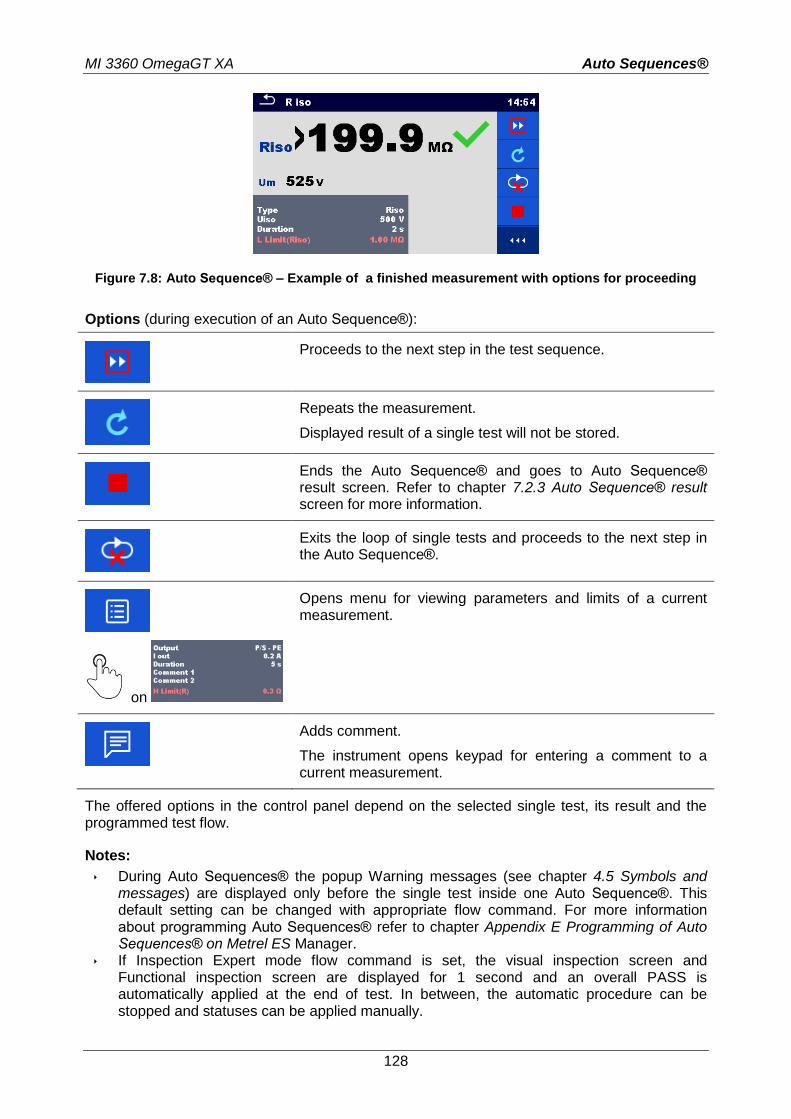
MI 3360 OmegaGT XA Auto Sequences®
128
Figure 7.8: Auto Sequence® – Example of a finished measurement with options for proceeding
Options (during execution of an Auto Sequence®):
Proceeds to the next step in the test sequence.
Repeats the measurement.
Displayed result of a single test will not be stored.
Ends the Auto Sequence® and goes to Auto Sequence® result screen. Refer to chapter 7.2.3 Auto Sequence® result screen for more information.
Exits the loop of single tests and proceeds to the next step in the Auto Sequence®.
on
Opens menu for viewing parameters and limits of a current measurement.
Adds comment.
The instrument opens keypad for entering a comment to a current measurement.
The offered options in the control panel depend on the selected single test, its result and the programmed test flow.
Notes:
During Auto Sequences® the popup Warning messages (see chapter 4.5 Symbols and messages) are displayed only before the single test inside one Auto Sequence®. This default setting can be changed with appropriate flow command. For more information about programming Auto Sequences® refer to chapter Appendix E Programming of Auto Sequences® on Metrel ES Manager.
If Inspection Expert mode flow command is set, the visual inspection screen and Functional inspection screen are displayed for 1 second and an overall PASS is automatically applied at the end of test. In between, the automatic procedure can be stopped and statuses can be applied manually.
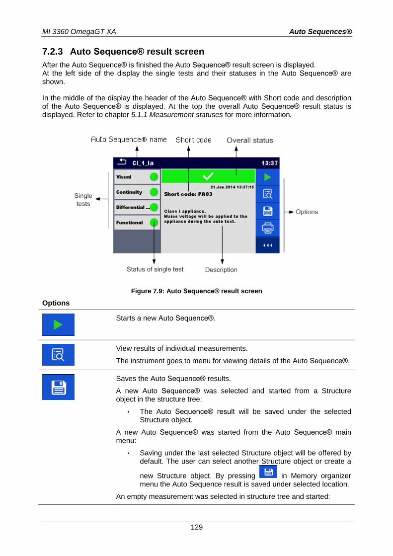
MI 3360 OmegaGT XA Auto Sequences®
129
7.2.3 Auto Sequence® result screen
After the Auto Sequence® is finished the Auto Sequence® result screen is displayed. At the left side of the display the single tests and their statuses in the Auto Sequence® are shown.
In the middle of the display the header of the Auto Sequence® with Short code and description of the Auto Sequence® is displayed. At the top the overall Auto Sequence® result status is displayed. Refer to chapter 5.1.1 Measurement statuses for more information.
Figure 7.9: Auto Sequence® result screen
Options
Starts a new Auto Sequence®.
View results of individual measurements.
The instrument goes to menu for viewing details of the Auto Sequence®.
Saves the Auto Sequence® results.
A new Auto Sequence® was selected and started from a Structure object in the structure tree:
The Auto Sequence® result will be saved under the selected Structure object.
A new Auto Sequence® was started from the Auto Sequence® main menu:
Saving under the last selected Structure object will be offered by default. The user can select another Structure object or create a
new Structure object. By pressing in Memory organizer menu the Auto Sequence result is saved under selected location.
An empty measurement was selected in structure tree and started:
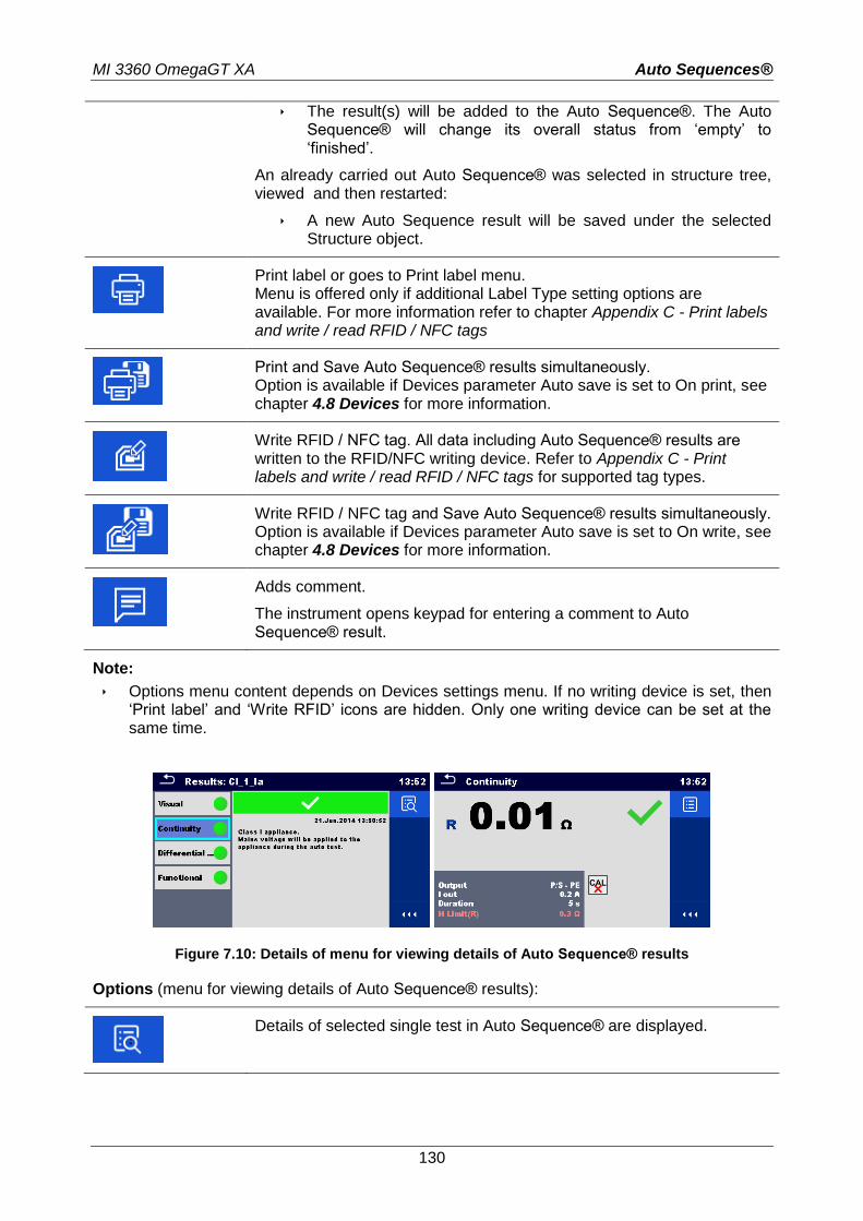
MI 3360 OmegaGT XA Auto Sequences®
130
The result(s) will be added to the Auto Sequence®. The Auto Sequence® will change its overall status from ‘empty’ to ‘finished’.
An already carried out Auto Sequence® was selected in structure tree, viewed and then restarted:
A new Auto Sequence result will be saved under the selected Structure object.
Print label or goes to Print label menu. Menu is offered only if additional Label Type setting options are available. For more information refer to chapter Appendix C - Print labels and write / read RFID / NFC tags
Print and Save Auto Sequence® results simultaneously. Option is available if Devices parameter Auto save is set to On print, see chapter 4.8 Devices for more information.
Write RFID / NFC tag. All data including Auto Sequence® results are written to the RFID/NFC writing device. Refer to Appendix C - Print labels and write / read RFID / NFC tags for supported tag types.
Write RFID / NFC tag and Save Auto Sequence® results simultaneously. Option is available if Devices parameter Auto save is set to On write, see chapter 4.8 Devices for more information.
Adds comment.
The instrument opens keypad for entering a comment to Auto Sequence® result.
Note:
Options menu content depends on Devices settings menu. If no writing device is set, then ‘Print label’ and ‘Write RFID’ icons are hidden. Only one writing device can be set at the same time.
Figure 7.10: Details of menu for viewing details of Auto Sequence® results
Options (menu for viewing details of Auto Sequence® results):
Details of selected single test in Auto Sequence® are displayed.
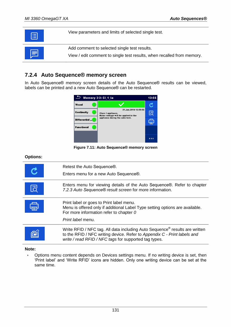
MI 3360 OmegaGT XA Auto Sequences®
131
View parameters and limits of selected single test.
Add comment to selected single test results.
View / edit comment to single test results, when recalled from memory.
7.2.4 Auto Sequence® memory screen
In Auto Sequence® memory screen details of the Auto Sequence® results can be viewed, labels can be printed and a new Auto Sequence® can be restarted.
Figure 7.11: Auto Sequence® memory screen
Options:
Retest the Auto Sequence®.
Enters menu for a new Auto Sequence®.
Enters menu for viewing details of the Auto Sequence®. Refer to chapter 7.2.3 Auto Sequence® result screen for more information.
Print label or goes to Print label menu. Menu is offered only if additional Label Type setting options are available. For more information refer to chapter 0
Print label menu.
Write RFID / NFC tag. All data including Auto Sequence® results are written to the RFID / NFC writing device. Refer to Appendix C - Print labels and write / read RFID / NFC tags for supported tag types.
Note:
Options menu content depends on Devices settings menu. If no writing device is set, then ‘Print label’ and ‘Write RFID’ icons are hidden. Only one writing device can be set at the same time.
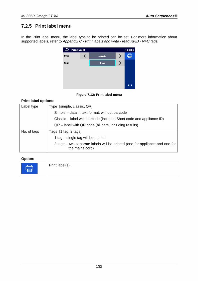
MI 3360 OmegaGT XA Auto Sequences®
132
7.2.5 Print label menu
In the Print label menu, the label type to be printed can be set. For more information about supported labels, refer to Appendix C - Print labels and write / read RFID / NFC tags.
Figure 7.12: Print label menu
Print label options:
Label type Type [simple, classic, QR]
Simple – data in text format, without barcode
Classic – label with barcode (includes Short code and appliance ID)
QR – label with QR code (all data, including results)
No. of tags Tags [1 tag, 2 tags]
1 tag – single tag will be printed
2 tags – two separate labels will be printed (one for appliance and one for the mains cord)
Option:
Print label(s).
MI 3360 OmegaGT XA Maintenance
133
8 Maintenance
8.1 Periodic calibration
It is essential that all measuring instruments are regularly calibrated in order for the technical specification listed in this manual to be guaranteed. We recommend an annual calibration.
8.2 Fuses
There are two fuses on the left side panel:
F1, F2: T 16 A / 250 V / (32 6,3) mm / 1500 A: intended for instrument protection. For position of fuses refer to chapter 3.1 Front panel.
Warnings!
Switch off the instrument and disconnect all test accessories and mains cord before replacing the fuses.
Replace blown fuses with the same type as defined in this document.
8.3 Service
For repairs under or out of warranty please contact your distributor for further information.
Unauthorized person is not allowed to open the OmegaGT XA instrument. There are no user replaceable parts inside the instrument.
8.4 Cleaning
Use a soft, slightly moistened cloth with soap water or alcohol to clean the surface of OmegaGT XA instrument. Leave the instrument to dry totally before using it.
Notes: Do not use liquids based on petrol or hydrocarbons! Do not spill cleaning liquid over the instrument!
MI 3360 OmegaGT XA Communications
134
9 Communications
The instrument can communicate with the Metrel ES Manager PC software. The following action is supported:
Saved results and Tree structure from Memory organizer can be downloaded and stored to a PC.
Tree structure and Auto Sequences® from Metrel ES Manager PC software can be uploaded to the instrument.
Metrel ES Manager is a PC software running on Windows 7, Windows 8, Windows 8.1 and Windows 10. There are three communication interfaces available on the instrument: RS-232, USB and Bluetooth. Instrument can also communicate to various external devices (android devices, test adapters, scanners, printers,…).
9.1 USB and RS232 communication with PC
The instrument automatically selects the communication mode according to detected interface. USB interface has priority. How to establish an USB or RS-232 link:
RS-232 communication: connect a PC COM port to the instrument PC / PRINTER connector using the RS232 serial communication cable;
USB communication: connect a PC USB port to the instrument USB connector using the USB interface cable.
Switch on the PC and the instrument.
Run the Metrel ES Manager software.
Select communication port (COM port for USB communication is identified as “Measurement Instrument USB VCom Port”).
The instrument is prepared to communicate with the PC.
9.2 Bluetooth communication
The internal Bluetooth module enables easy communication via Bluetooth with PC and Android devices. How to configure a Bluetooth link between instrument and PC
Switch On the instrument.
On PC configure a Standard Serial Port to enable communication over Bluetooth link between instrument and PC. Usually no code for pairing the devices is needed.
Run the Metrel ES Manager software.
Select configured communication port.
The instrument is prepared to communicate with the PC.
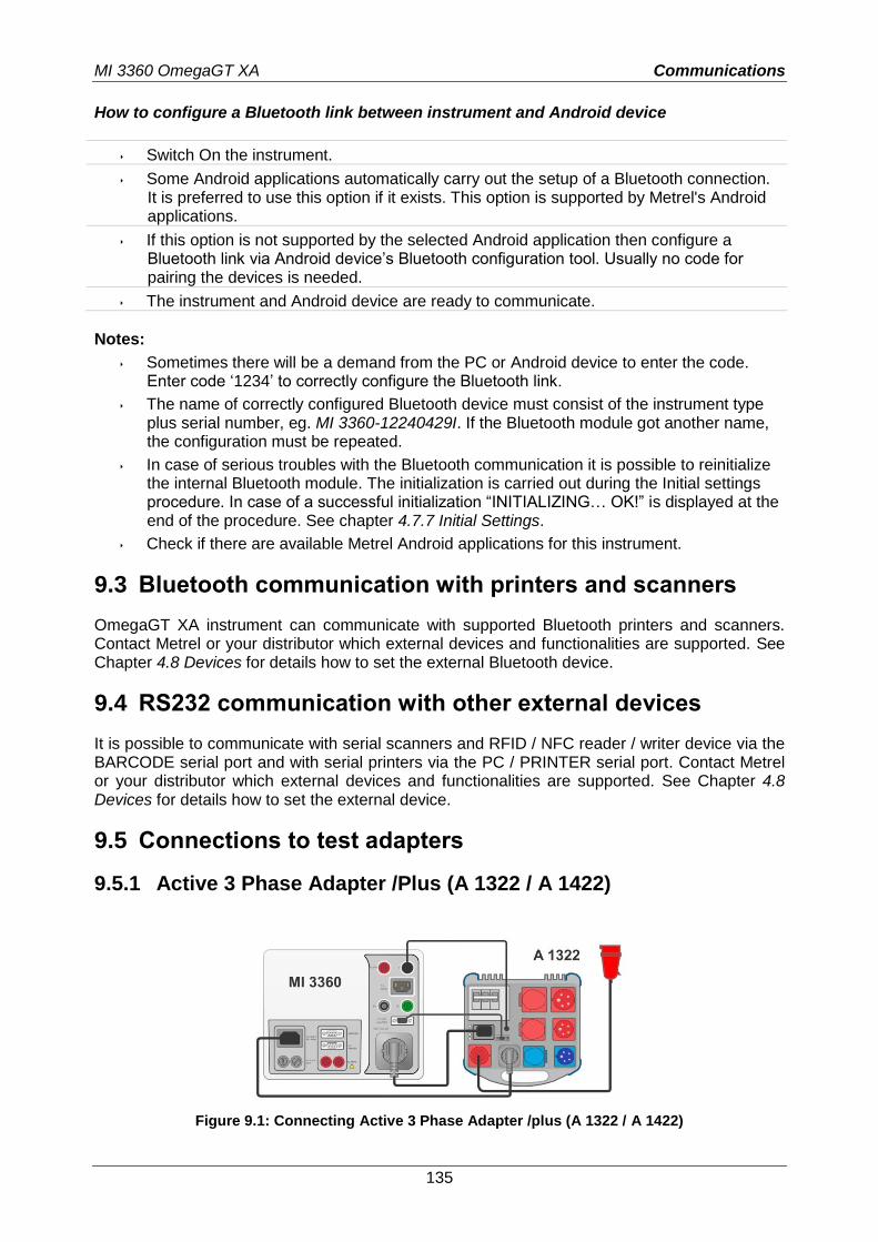
MI 3360 OmegaGT XA Communications
135
How to configure a Bluetooth link between instrument and Android device
Switch On the instrument.
Some Android applications automatically carry out the setup of a Bluetooth connection. It is preferred to use this option if it exists. This option is supported by Metrel's Android applications.
If this option is not supported by the selected Android application then configure a Bluetooth link via Android device’s Bluetooth configuration tool. Usually no code for pairing the devices is needed.
The instrument and Android device are ready to communicate.
Notes:
Sometimes there will be a demand from the PC or Android device to enter the code. Enter code ‘1234’ to correctly configure the Bluetooth link.
The name of correctly configured Bluetooth device must consist of the instrument type plus serial number, eg. MI 3360-12240429I. If the Bluetooth module got another name, the configuration must be repeated.
In case of serious troubles with the Bluetooth communication it is possible to reinitialize the internal Bluetooth module. The initialization is carried out during the Initial settings procedure. In case of a successful initialization “INITIALIZING… OK!” is displayed at the end of the procedure. See chapter 4.7.7 Initial Settings.
Check if there are available Metrel Android applications for this instrument.
9.3 Bluetooth communication with printers and scanners
OmegaGT XA instrument can communicate with supported Bluetooth printers and scanners. Contact Metrel or your distributor which external devices and functionalities are supported. See Chapter 4.8 Devices for details how to set the external Bluetooth device.
9.4 RS232 communication with other external devices
It is possible to communicate with serial scanners and RFID / NFC reader / writer device via the BARCODE serial port and with serial printers via the PC / PRINTER serial port. Contact Metrel or your distributor which external devices and functionalities are supported. See Chapter 4.8 Devices for details how to set the external device.
9.5 Connections to test adapters
9.5.1 Active 3 Phase Adapter /Plus (A 1322 / A 1422)
Figure 9.1: Connecting Active 3 Phase Adapter /plus (A 1322 / A 1422)
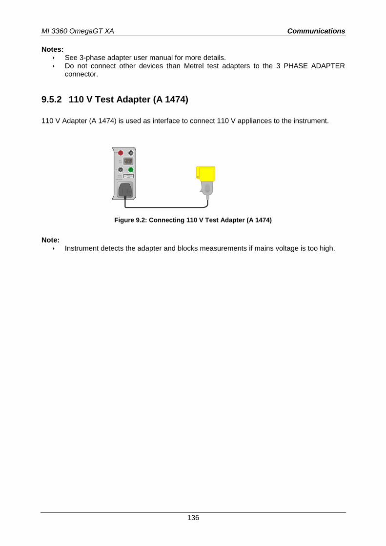
MI 3360 OmegaGT XA Communications
136
Notes: See 3-phase adapter user manual for more details. Do not connect other devices than Metrel test adapters to the 3 PHASE ADAPTER
connector.
9.5.2 110 V Test Adapter (A 1474)
110 V Adapter (A 1474) is used as interface to connect 110 V appliances to the instrument.
Figure 9.2: Connecting 110 V Test Adapter (A 1474)
Note:
Instrument detects the adapter and blocks measurements if mains voltage is too high.
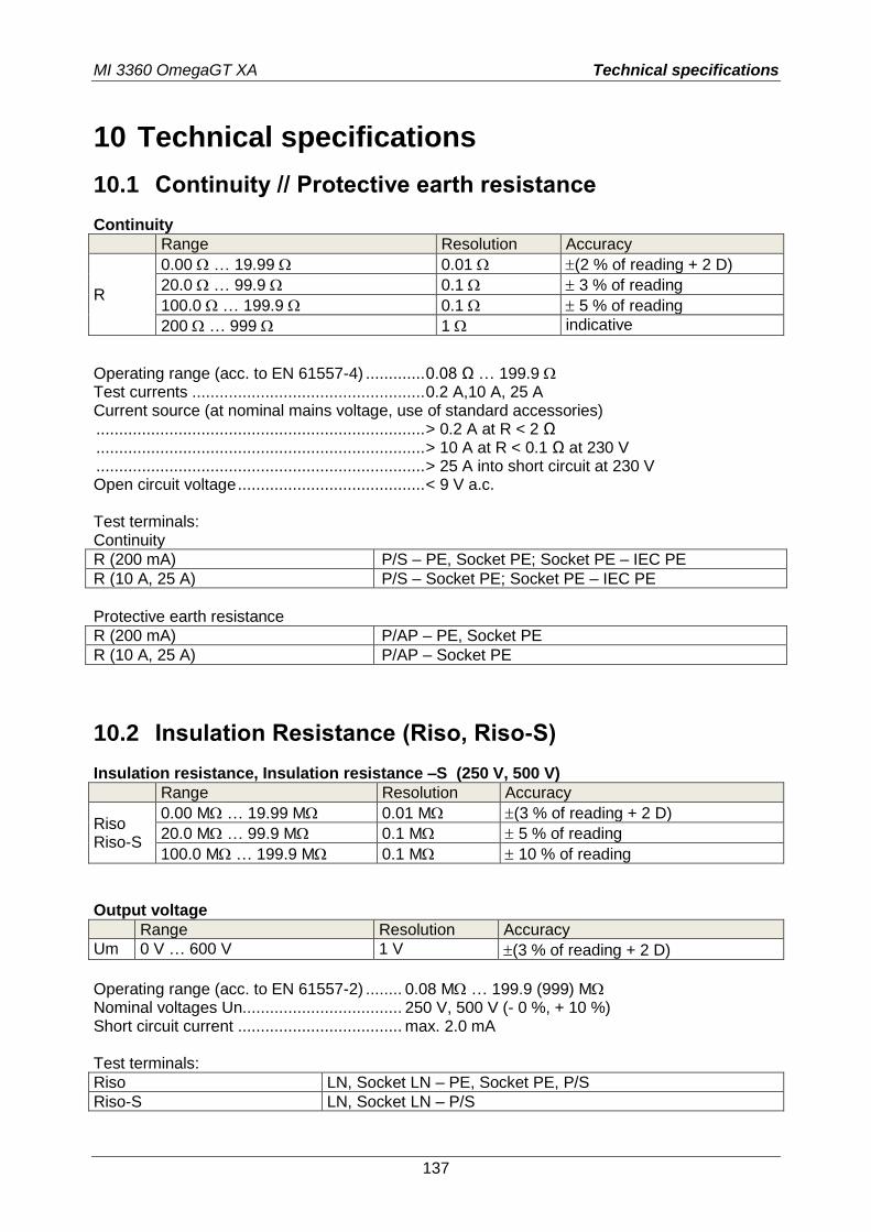
MI 3360 OmegaGT XA Technical specifications
137
10 Technical specifications
10.1 Continuity // Protective earth resistance
Continuity
Range Resolution Accuracy
R
0.00 … 19.99 0.01 (2 % of reading + 2 D)
20.0 … 99.9 0.1 3 % of reading
100.0 … 199.9 0.1 5 % of reading
200 … 999 1 indicative
Operating range (acc. to EN 61557-4) ............. 0.08 Ω … 199.9 Test currents ................................................... 0.2 A,10 A, 25 A Current source (at nominal mains voltage, use of standard accessories) ........................................................................ > 0.2 A at R < 2 Ω ........................................................................ > 10 A at R < 0.1 Ω at 230 V ........................................................................ > 25 A into short circuit at 230 V Open circuit voltage ......................................... < 9 V a.c. Test terminals: Continuity
R (200 mA) P/S – PE, Socket PE; Socket PE – IEC PE
R (10 A, 25 A) P/S – Socket PE; Socket PE – IEC PE
Protective earth resistance
R (200 mA) P/AP – PE, Socket PE
R (10 A, 25 A) P/AP – Socket PE
10.2 Insulation Resistance (Riso, Riso-S)
Insulation resistance, Insulation resistance –S (250 V, 500 V)
Range Resolution Accuracy
Riso Riso-S
0.00 M … 19.99 M 0.01 M (3 % of reading + 2 D)
20.0 M … 99.9 M 0.1 M 5 % of reading
100.0 M … 199.9 M 0.1 M 10 % of reading
Output voltage
Range Resolution Accuracy
Um 0 V … 600 V 1 V (3 % of reading + 2 D)
Operating range (acc. to EN 61557-2) ........ 0.08 M … 199.9 (999) M Nominal voltages Un................................... 250 V, 500 V (- 0 %, + 10 %) Short circuit current .................................... max. 2.0 mA Test terminals:
Riso LN, Socket LN – PE, Socket PE, P/S
Riso-S LN, Socket LN – P/S
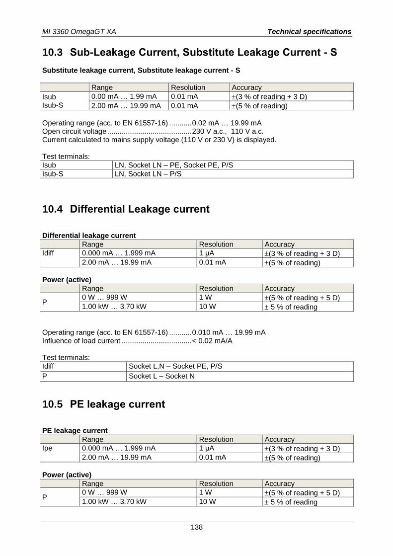
MI 3360 OmegaGT XA Technical specifications
138
10.3 Sub-Leakage Current, Substitute Leakage Current - S
Substitute leakage current, Substitute leakage current - S
Range Resolution Accuracy
Isub Isub-S
0.00 mA … 1.99 mA 0.01 mA (3 % of reading + 3 D)
2.00 mA … 19.99 mA 0.01 mA (5 % of reading)
Operating range (acc. to EN 61557-16) ........... 0.02 mA … 19.99 mA Open circuit voltage ......................................... 230 V a.c., 110 V a.c. Current calculated to mains supply voltage (110 V or 230 V) is displayed. Test terminals:
Isub LN, Socket LN – PE, Socket PE, P/S
Isub-S LN, Socket LN – P/S
10.4 Differential Leakage current
Differential leakage current
Range Resolution Accuracy
Idiff 0.000 mA … 1.999 mA 1 µA (3 % of reading + 3 D)
2.00 mA … 19.99 mA 0.01 mA (5 % of reading)
Power (active)
Range Resolution Accuracy
P 0 W … 999 W 1 W (5 % of reading + 5 D)
1.00 kW … 3.70 kW 10 W 5 % of reading
Operating range (acc. to EN 61557-16) ........... 0.010 mA … 19.99 mA Influence of load current .................................. < 0.02 mA/A Test terminals:
Idiff Socket L,N – Socket PE, P/S
P Socket L – Socket N
10.5 PE leakage current
PE leakage current
Range Resolution Accuracy
Ipe 0.000 mA … 1.999 mA 1 µA (3 % of reading + 3 D)
2.00 mA … 19.99 mA 0.01 mA (5 % of reading)
Power (active)
Range Resolution Accuracy
P 0 W … 999 W 1 W (5 % of reading + 5 D)
1.00 kW … 3.70 kW 10 W 5 % of reading
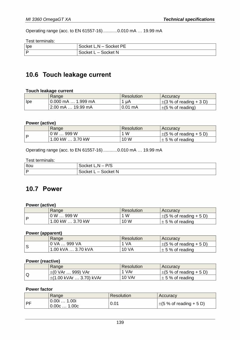
MI 3360 OmegaGT XA Technical specifications
139
Operating range (acc. to EN 61557-16) ........... 0.010 mA … 19.99 mA Test terminals:
Ipe Socket L,N – Socket PE
P Socket L – Socket N
10.6 Touch leakage current
Touch leakage current
Range Resolution Accuracy
Ipe 0.000 mA … 1.999 mA 1 µA (3 % of reading + 3 D)
2.00 mA … 19.99 mA 0.01 mA (5 % of reading)
Power (active)
Range Resolution Accuracy
P 0 W … 999 W 1 W (5 % of reading + 5 D)
1.00 kW … 3.70 kW 10 W 5 % of reading
Operating range (acc. to EN 61557-16) ........... 0.010 mA … 19.99 mA Test terminals:
Itou Socket L,N – P/S
P Socket L – Socket N
10.7 Power
Power (active)
Range Resolution Accuracy
P 0 W … 999 W 1 W (5 % of reading + 5 D)
1.00 kW … 3.70 kW 10 W 5 % of reading
Power (apparent)
Range Resolution Accuracy
S 0 VA … 999 VA 1 VA (5 % of reading + 5 D)
1.00 kVA … 3.70 kVA 10 VA 5 % of reading
Power (reactive)
Range Resolution Accuracy
Q (0 VAr … 999) VAr 1 VAr (5 % of reading + 5 D)
(1.00 kVAr … 3.70) kVAr 10 VAr 5 % of reading
Power factor
Range Resolution Accuracy
PF 0.00i … 1.00i 0.00c … 1.00c
0.01 (5 % of reading + 5 D)
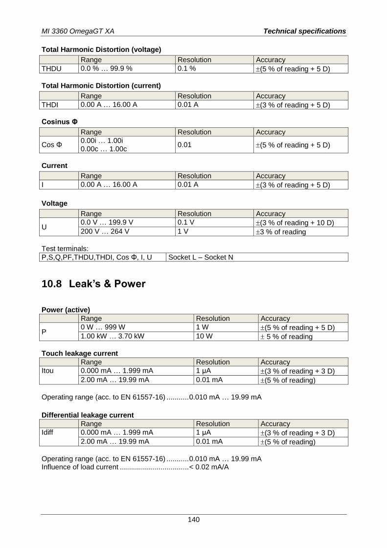
MI 3360 OmegaGT XA Technical specifications
140
Total Harmonic Distortion (voltage)
Range Resolution Accuracy
THDU 0.0 % … 99.9 % 0.1 % (5 % of reading + 5 D)
Total Harmonic Distortion (current)
Range Resolution Accuracy
THDI 0.00 A … 16.00 A 0.01 A (3 % of reading + 5 D)
Cosinus Φ
Range Resolution Accuracy
Cos Φ 0.00i … 1.00i 0.00c … 1.00c
0.01 (5 % of reading + 5 D)
Current
Range Resolution Accuracy
I 0.00 A … 16.00 A 0.01 A (3 % of reading + 5 D)
Voltage
Range Resolution Accuracy
U 0.0 V … 199.9 V 0.1 V (3 % of reading + 10 D)
200 V … 264 V 1 V 3 % of reading
Test terminals:
P,S,Q,PF,THDU,THDI, Cos Φ, I, U Socket L – Socket N
10.8 Leak’s & Power
Power (active)
Range Resolution Accuracy
P 0 W … 999 W 1 W (5 % of reading + 5 D)
1.00 kW … 3.70 kW 10 W 5 % of reading
Touch leakage current
Range Resolution Accuracy
Itou 0.000 mA … 1.999 mA 1 µA (3 % of reading + 3 D)
2.00 mA … 19.99 mA 0.01 mA (5 % of reading)
Operating range (acc. to EN 61557-16) ........... 0.010 mA … 19.99 mA
Differential leakage current
Range Resolution Accuracy
Idiff 0.000 mA … 1.999 mA 1 µA (3 % of reading + 3 D)
2.00 mA … 19.99 mA 0.01 mA (5 % of reading)
Operating range (acc. to EN 61557-16) ........... 0.010 mA … 19.99 mA Influence of load current .................................. < 0.02 mA/A
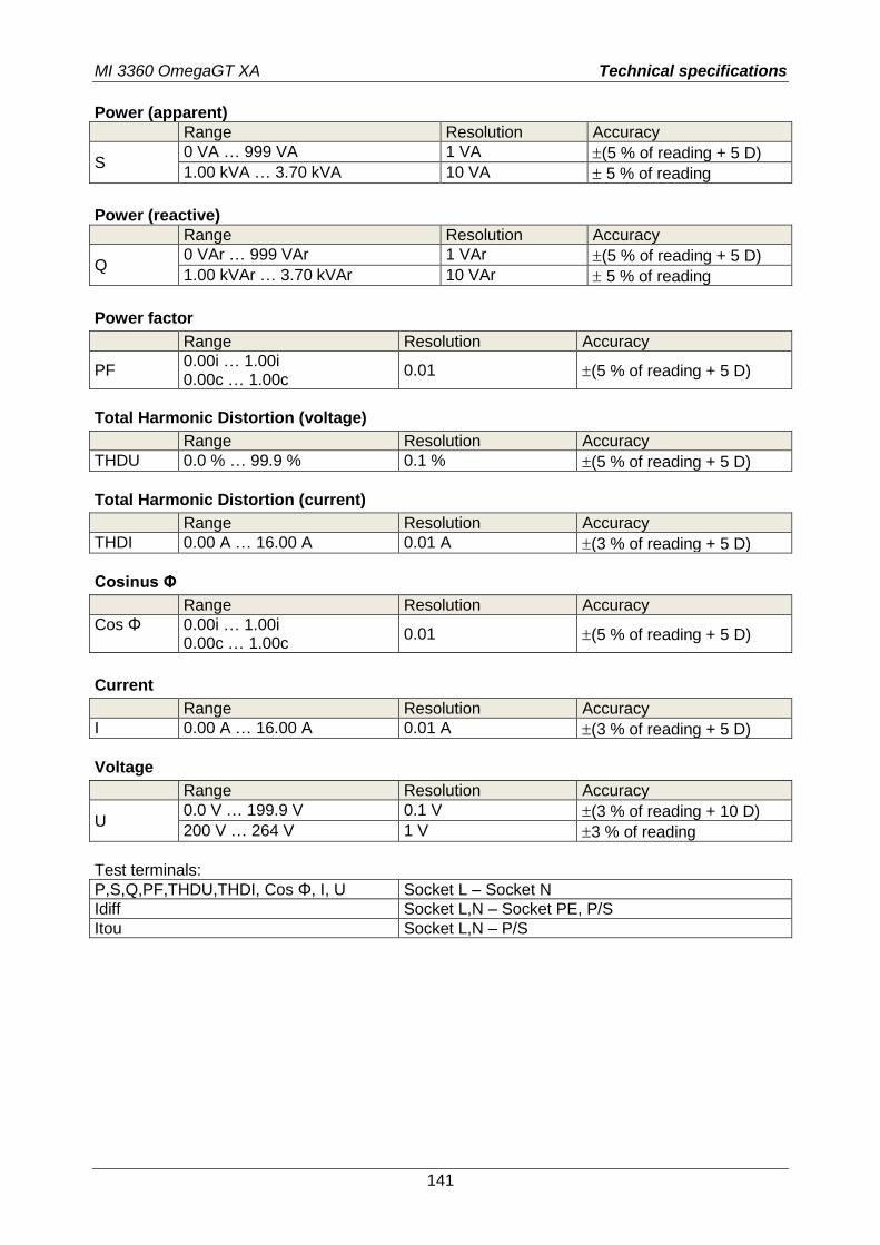
MI 3360 OmegaGT XA Technical specifications
141
Power (apparent)
Range Resolution Accuracy
S 0 VA … 999 VA 1 VA (5 % of reading + 5 D)
1.00 kVA … 3.70 kVA 10 VA 5 % of reading
Power (reactive)
Range Resolution Accuracy
Q 0 VAr … 999 VAr 1 VAr (5 % of reading + 5 D)
1.00 kVAr … 3.70 kVAr 10 VAr 5 % of reading
Power factor
Range Resolution Accuracy
PF 0.00i … 1.00i 0.00c … 1.00c
0.01 (5 % of reading + 5 D)
Total Harmonic Distortion (voltage)
Range Resolution Accuracy
THDU 0.0 % … 99.9 % 0.1 % (5 % of reading + 5 D)
Total Harmonic Distortion (current)
Range Resolution Accuracy
THDI 0.00 A … 16.00 A 0.01 A (3 % of reading + 5 D)
Cosinus Φ
Range Resolution Accuracy
Cos Φ 0.00i … 1.00i 0.00c … 1.00c
0.01 (5 % of reading + 5 D)
Current
Range Resolution Accuracy
I 0.00 A … 16.00 A 0.01 A (3 % of reading + 5 D)
Voltage
Range Resolution Accuracy
U 0.0 V … 199.9 V 0.1 V (3 % of reading + 10 D)
200 V … 264 V 1 V 3 % of reading
Test terminals:
P,S,Q,PF,THDU,THDI, Cos Φ, I, U Socket L – Socket N
Idiff Socket L,N – Socket PE, P/S
Itou Socket L,N – P/S
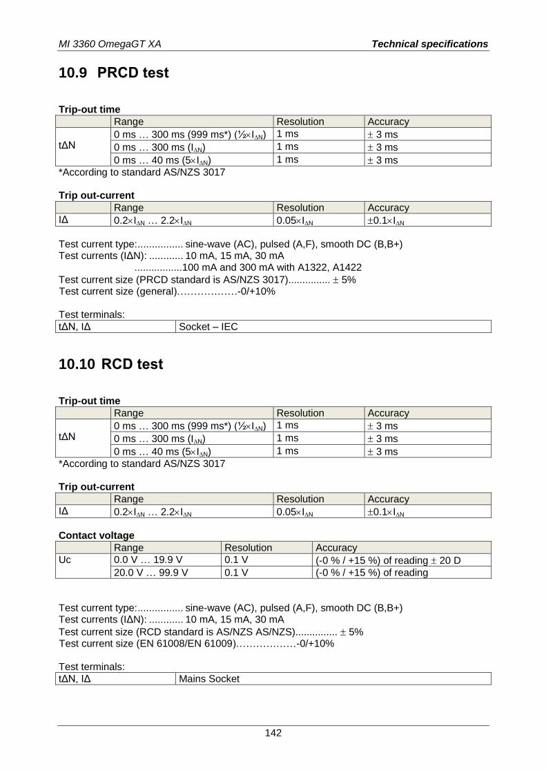
MI 3360 OmegaGT XA Technical specifications
142
10.9 PRCD test
Trip-out time
Range Resolution Accuracy
tΔN
0 ms … 300 ms (999 ms*) (½IN) 1 ms 3 ms
0 ms … 300 ms (IN) 1 ms 3 ms
0 ms … 40 ms (5IN) 1 ms 3 ms
*According to standard AS/NZS 3017 Trip out-current
Range Resolution Accuracy
IΔ 0.2IN … 2.2IN 0.05IN 0.1IN
Test current type: ................ sine-wave (AC), pulsed (A,F), smooth DC (B,B+) Test currents (IΔN): ............ 10 mA, 15 mA, 30 mA .................100 mA and 300 mA with A1322, A1422
Test current size (PRCD standard is AS/NZS 3017)............... 5% Test current size (general)………………-0/+10% Test terminals:
tΔN, IΔ Socket – IEC
10.10 RCD test
Trip-out time
Range Resolution Accuracy
tΔN
0 ms … 300 ms (999 ms*) (½IN) 1 ms 3 ms
0 ms … 300 ms (IN) 1 ms 3 ms
0 ms … 40 ms (5IN) 1 ms 3 ms
*According to standard AS/NZS 3017 Trip out-current
Range Resolution Accuracy
IΔ 0.2IN … 2.2IN 0.05IN 0.1IN
Contact voltage
Range Resolution Accuracy
Uc 0.0 V … 19.9 V 0.1 V (-0 % / +15 %) of reading 20 D
20.0 V … 99.9 V 0.1 V (-0 % / +15 %) of reading
Test current type: ................ sine-wave (AC), pulsed (A,F), smooth DC (B,B+) Test currents (IΔN): ............ 10 mA, 15 mA, 30 mA
Test current size (RCD standard is AS/NZS AS/NZS)............... 5% Test current size (EN 61008/EN 61009)………………-0/+10% Test terminals:
tΔN, IΔ Mains Socket
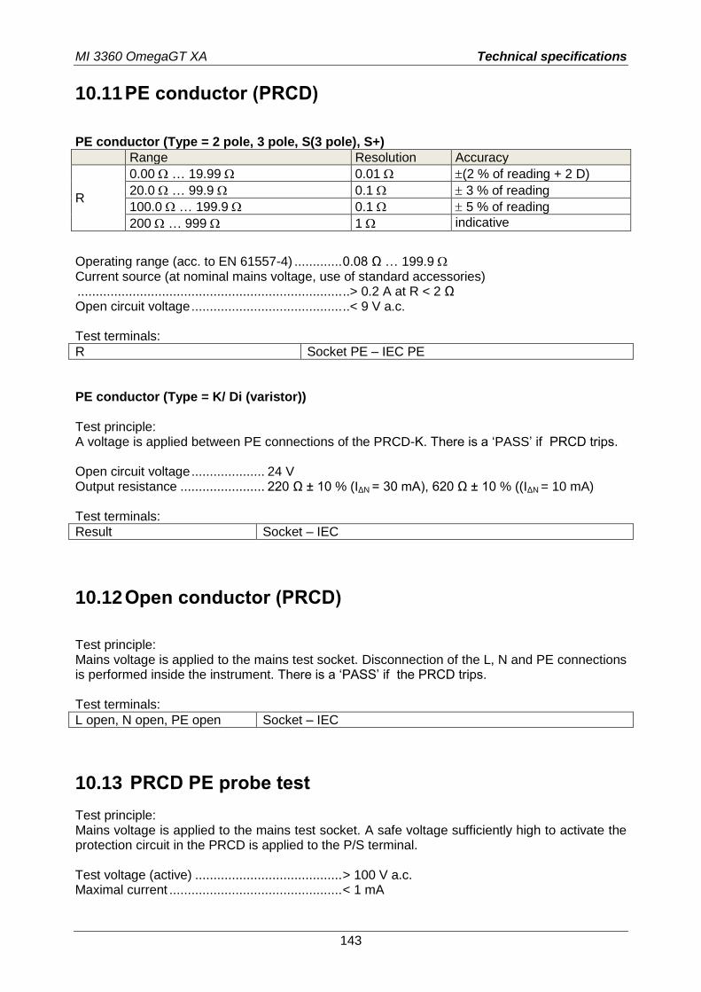
MI 3360 OmegaGT XA Technical specifications
143
10.11 PE conductor (PRCD)
PE conductor (Type = 2 pole, 3 pole, S(3 pole), S+)
Range Resolution Accuracy
R
0.00 … 19.99 0.01 (2 % of reading + 2 D)
20.0 … 99.9 0.1 3 % of reading
100.0 … 199.9 0.1 5 % of reading
200 … 999 1 indicative
Operating range (acc. to EN 61557-4) ............. 0.08 Ω … 199.9 Current source (at nominal mains voltage, use of standard accessories) ........................................................................ ..> 0.2 A at R < 2 Ω Open circuit voltage ......................................... ..< 9 V a.c. Test terminals:
R Socket PE – IEC PE
PE conductor (Type = K/ Di (varistor)) Test principle: A voltage is applied between PE connections of the PRCD-K. There is a ‘PASS’ if PRCD trips. Open circuit voltage .................... 24 V Output resistance ....................... 220 Ω ± 10 % (IΔN = 30 mA), 620 Ω ± 10 % ((IΔN = 10 mA) Test terminals:
Result Socket – IEC
10.12 Open conductor (PRCD)
Test principle: Mains voltage is applied to the mains test socket. Disconnection of the L, N and PE connections is performed inside the instrument. There is a ‘PASS’ if the PRCD trips. Test terminals:
L open, N open, PE open Socket – IEC
10.13 PRCD PE probe test
Test principle: Mains voltage is applied to the mains test socket. A safe voltage sufficiently high to activate the protection circuit in the PRCD is applied to the P/S terminal. Test voltage (active) ........................................ > 100 V a.c. Maximal current ............................................... < 1 mA
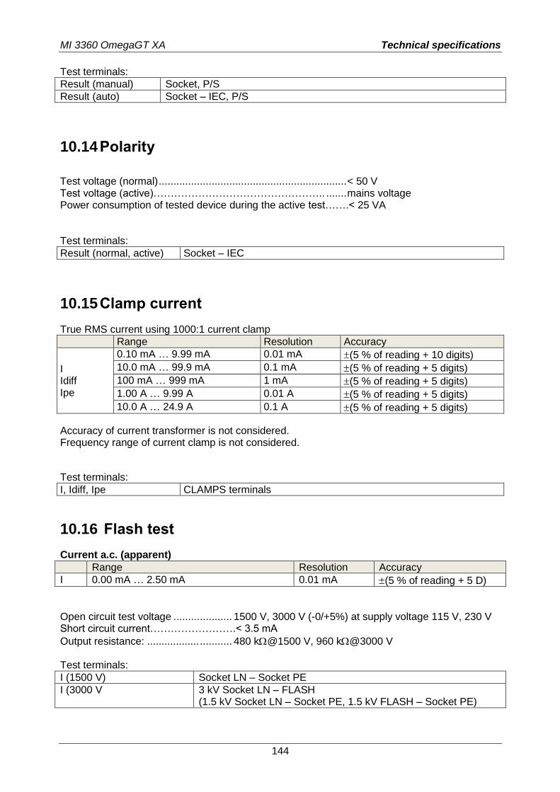
MI 3360 OmegaGT XA Technical specifications
144
Test terminals:
Result (manual) Socket, P/S
Result (auto) Socket – IEC, P/S
10.14 Polarity
Test voltage (normal) ................................................................ < 50 V Test voltage (active)………………………………………….. ....... mains voltage Power consumption of tested device during the active test…….< 25 VA Test terminals:
Result (normal, active) Socket – IEC
10.15 Clamp current
True RMS current using 1000:1 current clamp
Range Resolution Accuracy
I Idiff Ipe
0.10 mA … 9.99 mA 0.01 mA (5 % of reading + 10 digits)
10.0 mA … 99.9 mA 0.1 mA (5 % of reading + 5 digits)
100 mA … 999 mA 1 mA (5 % of reading + 5 digits)
1.00 A … 9.99 A 0.01 A (5 % of reading + 5 digits)
10.0 A … 24.9 A 0.1 A (5 % of reading + 5 digits)
Accuracy of current transformer is not considered. Frequency range of current clamp is not considered.
Test terminals:
I, Idiff, Ipe CLAMPS terminals
10.16 Flash test
Current a.c. (apparent)
Range Resolution Accuracy
I 0.00 mA … 2.50 mA 0.01 mA (5 % of reading + 5 D)
Open circuit test voltage .................... 1500 V, 3000 V (-0/+5%) at supply voltage 115 V, 230 V Short circuit current…………………….< 3.5 mA
Output resistance: .................. ........... 480 k@1500 V, 960 k@3000 V Test terminals:
I (1500 V) Socket LN – Socket PE
I (3000 V 3 kV Socket LN – FLASH (1.5 kV Socket LN – Socket PE, 1.5 kV FLASH – Socket PE)
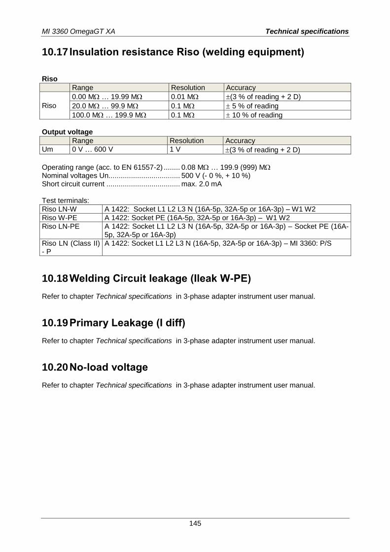
MI 3360 OmegaGT XA Technical specifications
145
10.17 Insulation resistance Riso (welding equipment)
Riso
Range Resolution Accuracy
Riso
0.00 M … 19.99 M 0.01 M (3 % of reading + 2 D)
20.0 M … 99.9 M 0.1 M 5 % of reading
100.0 M … 199.9 M 0.1 M 10 % of reading
Output voltage
Range Resolution Accuracy
Um 0 V … 600 V 1 V (3 % of reading + 2 D)
Operating range (acc. to EN 61557-2) ........ 0.08 M … 199.9 (999) M Nominal voltages Un................................... 500 V (- 0 %, + 10 %) Short circuit current .................................... max. 2.0 mA Test terminals:
Riso LN-W A 1422: Socket L1 L2 L3 N (16A-5p, 32A-5p or 16A-3p) – W1 W2
Riso W-PE A 1422: Socket PE (16A-5p, 32A-5p or 16A-3p) – W1 W2
Riso LN-PE A 1422: Socket L1 L2 L3 N (16A-5p, 32A-5p or 16A-3p) – Socket PE (16A-5p, 32A-5p or 16A-3p)
Riso LN (Class II) - P
A 1422: Socket L1 L2 L3 N (16A-5p, 32A-5p or 16A-3p) – MI 3360: P/S
10.18 Welding Circuit leakage (Ileak W-PE)
Refer to chapter Technical specifications in 3-phase adapter instrument user manual.
10.19 Primary Leakage (I diff)
Refer to chapter Technical specifications in 3-phase adapter instrument user manual.
10.20 No-load voltage
Refer to chapter Technical specifications in 3-phase adapter instrument user manual.
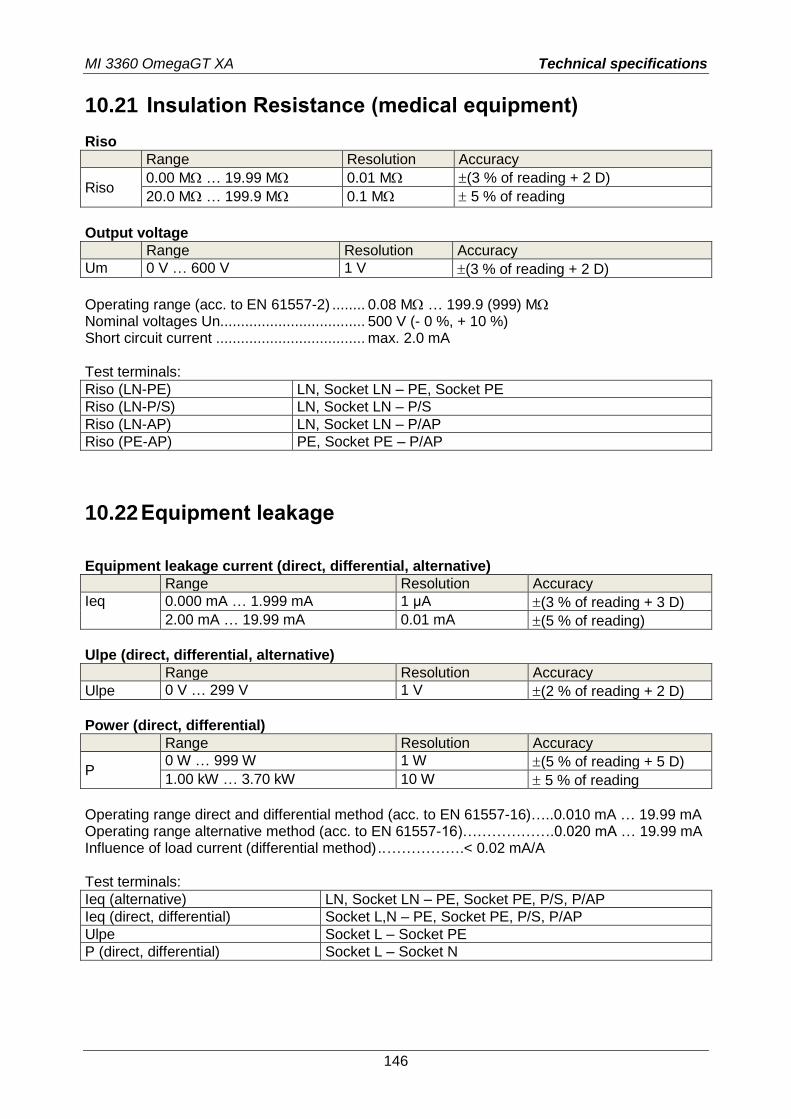
MI 3360 OmegaGT XA Technical specifications
146
10.21 Insulation Resistance (medical equipment)
Riso
Range Resolution Accuracy
Riso 0.00 M … 19.99 M 0.01 M (3 % of reading + 2 D)
20.0 M … 199.9 M 0.1 M 5 % of reading
Output voltage
Range Resolution Accuracy
Um 0 V … 600 V 1 V (3 % of reading + 2 D)
Operating range (acc. to EN 61557-2) ........ 0.08 M … 199.9 (999) M Nominal voltages Un................................... 500 V (- 0 %, + 10 %) Short circuit current .................................... max. 2.0 mA Test terminals:
Riso (LN-PE) LN, Socket LN – PE, Socket PE
Riso (LN-P/S) LN, Socket LN – P/S
Riso (LN-AP) LN, Socket LN – P/AP
Riso (PE-AP) PE, Socket PE – P/AP
10.22 Equipment leakage
Equipment leakage current (direct, differential, alternative)
Range Resolution Accuracy
Ieq 0.000 mA … 1.999 mA 1 µA (3 % of reading + 3 D)
2.00 mA … 19.99 mA 0.01 mA (5 % of reading)
Ulpe (direct, differential, alternative)
Range Resolution Accuracy
Ulpe 0 V … 299 V 1 V (2 % of reading + 2 D)
Power (direct, differential)
Range Resolution Accuracy
P 0 W … 999 W 1 W (5 % of reading + 5 D)
1.00 kW … 3.70 kW 10 W 5 % of reading
Operating range direct and differential method (acc. to EN 61557-16)…..0.010 mA … 19.99 mA Operating range alternative method (acc. to EN 61557-16)……………….0.020 mA … 19.99 mA Influence of load current (differential method) .. …………….< 0.02 mA/A Test terminals:
Ieq (alternative) LN, Socket LN – PE, Socket PE, P/S, P/AP
Ieq (direct, differential) Socket L,N – PE, Socket PE, P/S, P/AP
Ulpe Socket L – Socket PE
P (direct, differential) Socket L – Socket N
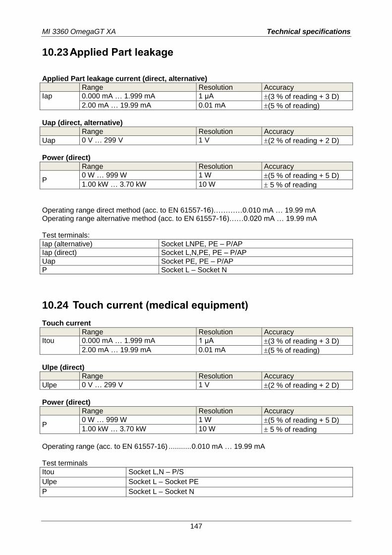
MI 3360 OmegaGT XA Technical specifications
147
10.23 Applied Part leakage
Applied Part leakage current (direct, alternative)
Range Resolution Accuracy
Iap 0.000 mA … 1.999 mA 1 µA (3 % of reading + 3 D)
2.00 mA … 19.99 mA 0.01 mA (5 % of reading)
Uap (direct, alternative)
Range Resolution Accuracy
Uap 0 V … 299 V 1 V (2 % of reading + 2 D)
Power (direct)
Range Resolution Accuracy
P 0 W … 999 W 1 W (5 % of reading + 5 D)
1.00 kW … 3.70 kW 10 W 5 % of reading
Operating range direct method (acc. to EN 61557-16)…………0.010 mA … 19.99 mA Operating range alternative method (acc. to EN 61557-16)……0.020 mA … 19.99 mA Test terminals:
Iap (alternative) Socket LNPE, PE – P/AP
Iap (direct) Socket L,N,PE, PE – P/AP
Uap Socket PE, PE – P/AP
P Socket L – Socket N
10.24 Touch current (medical equipment)
Touch current
Range Resolution Accuracy
Itou 0.000 mA … 1.999 mA 1 µA (3 % of reading + 3 D)
2.00 mA … 19.99 mA 0.01 mA (5 % of reading)
Ulpe (direct)
Range Resolution Accuracy
Ulpe 0 V … 299 V 1 V (2 % of reading + 2 D)
Power (direct)
Range Resolution Accuracy
P 0 W … 999 W 1 W (5 % of reading + 5 D)
1.00 kW … 3.70 kW 10 W 5 % of reading
Operating range (acc. to EN 61557-16) ........... 0.010 mA … 19.99 mA Test terminals
Itou Socket L,N – P/S
Ulpe Socket L – Socket PE
P Socket L – Socket N
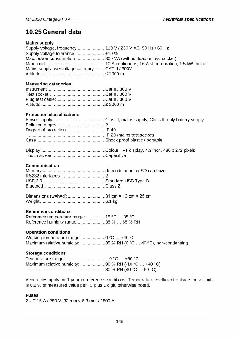
MI 3360 OmegaGT XA Technical specifications
148
10.25 General data
Mains supply Supply voltage, frequency ...................... 110 V / 230 V AC, 50 Hz / 60 Hz
Supply voltage tolerance ........................ 10 % Max. power consumption ........................ 300 VA (without load on test socket) Max. load………………………. ............... 10 A continuous, 16 A short duration, 1.5 kW motor Mains supply overvoltage category ......... CAT II / 300V Altitude ................................................... ≤ 2000 m
Measuring categories Instrument: ............................................. Cat II / 300 V Test socket: ............................................ Cat II / 300 V Plug test cable: ....................................... Cat II / 300 V Altitude ................................................... ≤ 2000 m Protection classifications Power supply……………………… .......... Class I, mains supply, Class II, only battery supply Pollution degree ...................................... 2 Degree of protection ............................... IP 40 ............................................................... IP 20 (mains test socket) Case ....................................................... Shock proof plastic / portable Display ................................................... Colour TFT display, 4.3 inch, 480 x 272 pixels Touch screen .......................................... Capacitive Communication Memory .................................................. depends on microSD card size RS232 interfaces .................................... 2 USB 2.0 .................................................. Standard USB Type B Bluetooth ................................................ Class 2 Dimensions (w×h×d): .............................. 31 cm × 13 cm × 25 cm Weight .................................................... 6.1 kg Reference conditions
Reference temperature range: ................ 15 C … 35 C Reference humidity range: ...................... 35 % … 65 % RH Operation conditions
Working temperature range: ................... 0 C … +40 C
Maximum relative humidity: .................... 85 % RH (0 C … 40 C), non-condensing Storage conditions
Temperature range: ................................ -10 C … +60 C
Maximum relative humidity: .................... 90 % RH (-10 C … +40 C)
............................................................... 80 % RH (40 C … 60 C) Accuracies apply for 1 year in reference conditions. Temperature coefficient outside these limits
is 0.2 % of measured value per C plus 1 digit, otherwise noted. Fuses
2 x T 16 A / 250 V, 32 mm 6.3 mm / 1500 A
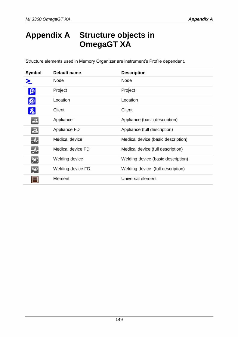
MI 3360 OmegaGT XA Appendix A
149
Appendix A Structure objects in OmegaGT XA
Structure elements used in Memory Organizer are instrument’s Profile dependent.
Symbol Default name Description
Node Node
Project Project
Location Location
Client Client
Appliance Appliance (basic description)
Appliance FD Appliance (full description)
Medical device Medical device (basic description)
Medical device FD Medical device (full description)
Welding device Welding device (basic description)
Welding device FD Welding device (full description)
Element Universal element

MI 3360 OmegaGT XA Appendix B
150
Appendix B Profile Notes
There are no specific profile notes for OmegaGT XA MI 3360.
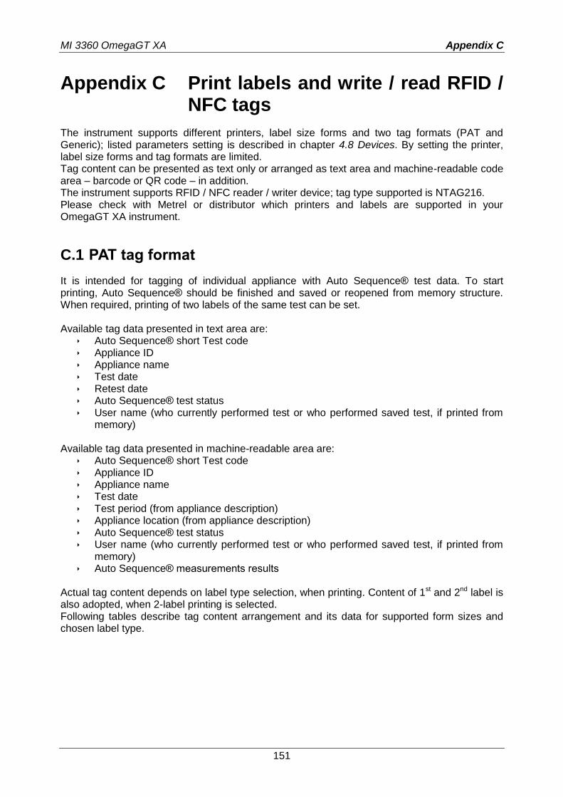
MI 3360 OmegaGT XA Appendix C
151
Appendix C Print labels and write / read RFID / NFC tags
The instrument supports different printers, label size forms and two tag formats (PAT and Generic); listed parameters setting is described in chapter 4.8 Devices. By setting the printer, label size forms and tag formats are limited. Tag content can be presented as text only or arranged as text area and machine-readable code area – barcode or QR code – in addition. The instrument supports RFID / NFC reader / writer device; tag type supported is NTAG216. Please check with Metrel or distributor which printers and labels are supported in your OmegaGT XA instrument.
C.1 PAT tag format
It is intended for tagging of individual appliance with Auto Sequence® test data. To start printing, Auto Sequence® should be finished and saved or reopened from memory structure. When required, printing of two labels of the same test can be set. Available tag data presented in text area are:
Auto Sequence® short Test code Appliance ID Appliance name Test date Retest date Auto Sequence® test status User name (who currently performed test or who performed saved test, if printed from
memory) Available tag data presented in machine-readable area are:
Auto Sequence® short Test code Appliance ID Appliance name Test date Test period (from appliance description) Appliance location (from appliance description) Auto Sequence® test status User name (who currently performed test or who performed saved test, if printed from
memory) Auto Sequence® measurements results
Actual tag content depends on label type selection, when printing. Content of 1st and 2nd label is also adopted, when 2-label printing is selected. Following tables describe tag content arrangement and its data for supported form sizes and chosen label type.
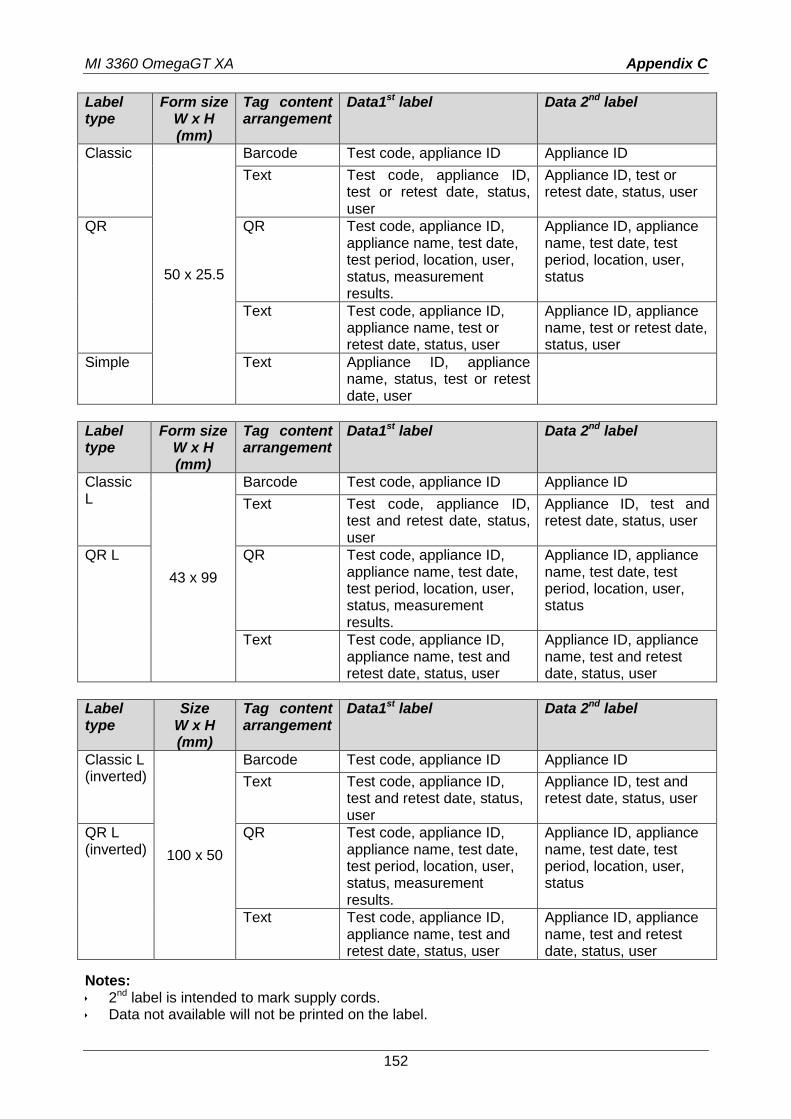
MI 3360 OmegaGT XA Appendix C
152
Label type
Form size W x H (mm)
Tag content arrangement
Data1st label Data 2nd label
Classic
50 x 25.5
Barcode Test code, appliance ID Appliance ID
Text Test code, appliance ID, test or retest date, status, user
Appliance ID, test or retest date, status, user
QR QR Test code, appliance ID, appliance name, test date, test period, location, user, status, measurement results.
Appliance ID, appliance name, test date, test period, location, user, status
Text Test code, appliance ID, appliance name, test or retest date, status, user
Appliance ID, appliance name, test or retest date, status, user
Simple Text Appliance ID, appliance name, status, test or retest date, user
Label type
Form size W x H (mm)
Tag content arrangement
Data1st label Data 2nd label
Classic L
43 x 99
Barcode Test code, appliance ID Appliance ID
Text Test code, appliance ID, test and retest date, status, user
Appliance ID, test and retest date, status, user
QR L QR Test code, appliance ID, appliance name, test date, test period, location, user, status, measurement results.
Appliance ID, appliance name, test date, test period, location, user, status
Text Test code, appliance ID, appliance name, test and retest date, status, user
Appliance ID, appliance name, test and retest date, status, user
Label type
Size W x H (mm)
Tag content arrangement
Data1st label Data 2nd label
Classic L (inverted)
100 x 50
Barcode Test code, appliance ID Appliance ID
Text Test code, appliance ID, test and retest date, status, user
Appliance ID, test and retest date, status, user
QR L (inverted)
QR Test code, appliance ID, appliance name, test date, test period, location, user, status, measurement results.
Appliance ID, appliance name, test date, test period, location, user, status
Text Test code, appliance ID, appliance name, test and retest date, status, user
Appliance ID, appliance name, test and retest date, status, user
Notes: 2nd label is intended to mark supply cords. Data not available will not be printed on the label.
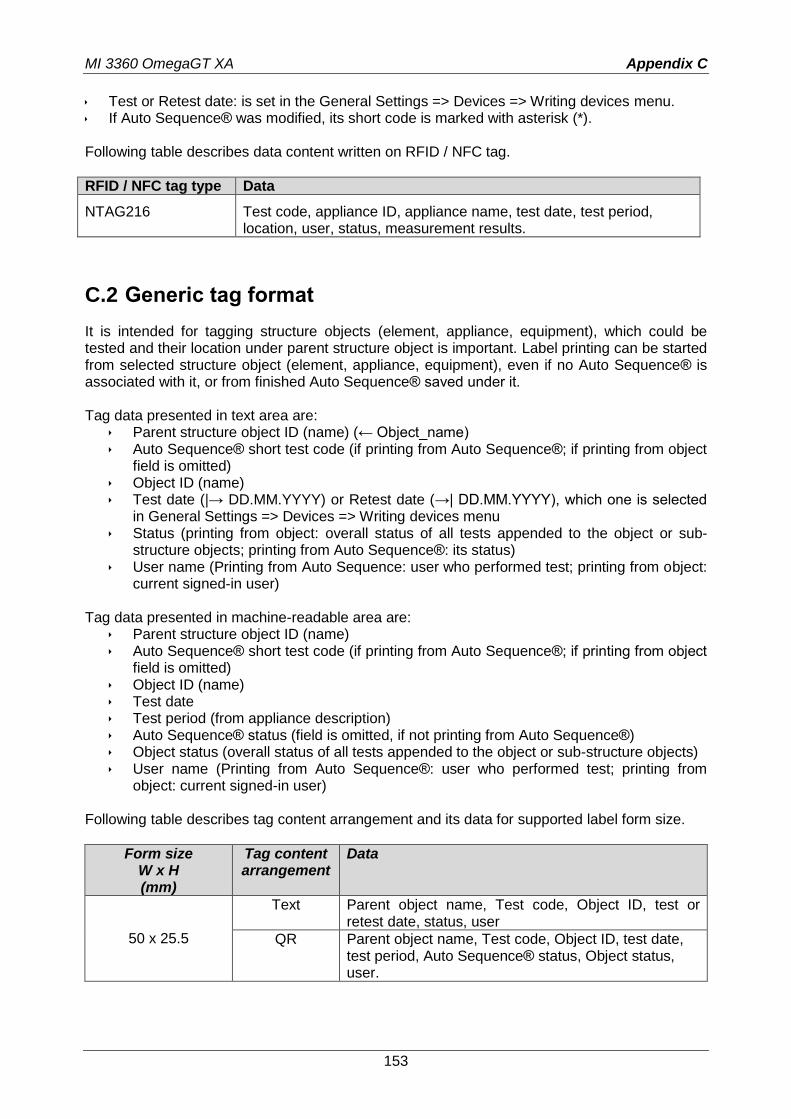
MI 3360 OmegaGT XA Appendix C
153
Test or Retest date: is set in the General Settings => Devices => Writing devices menu. If Auto Sequence® was modified, its short code is marked with asterisk (*). Following table describes data content written on RFID / NFC tag.
RFID / NFC tag type Data
NTAG216 Test code, appliance ID, appliance name, test date, test period, location, user, status, measurement results.
C.2 Generic tag format
It is intended for tagging structure objects (element, appliance, equipment), which could be tested and their location under parent structure object is important. Label printing can be started from selected structure object (element, appliance, equipment), even if no Auto Sequence® is associated with it, or from finished Auto Sequence® saved under it. Tag data presented in text area are:
Parent structure object ID (name) (← Object_name) Auto Sequence® short test code (if printing from Auto Sequence®; if printing from object
field is omitted) Object ID (name) Test date (|→ DD.MM.YYYY) or Retest date (→| DD.MM.YYYY), which one is selected
in General Settings => Devices => Writing devices menu Status (printing from object: overall status of all tests appended to the object or sub-
structure objects; printing from Auto Sequence®: its status) User name (Printing from Auto Sequence: user who performed test; printing from object:
current signed-in user) Tag data presented in machine-readable area are:
Parent structure object ID (name) Auto Sequence® short test code (if printing from Auto Sequence®; if printing from object
field is omitted) Object ID (name) Test date Test period (from appliance description) Auto Sequence® status (field is omitted, if not printing from Auto Sequence®) Object status (overall status of all tests appended to the object or sub-structure objects) User name (Printing from Auto Sequence®: user who performed test; printing from
object: current signed-in user) Following table describes tag content arrangement and its data for supported label form size.
Form size W x H (mm)
Tag content arrangement
Data
50 x 25.5
Text Parent object name, Test code, Object ID, test or retest date, status, user
QR Parent object name, Test code, Object ID, test date, test period, Auto Sequence® status, Object status, user.
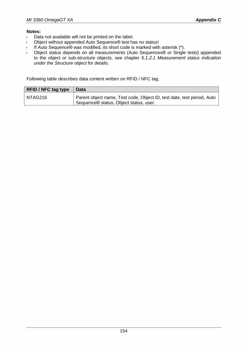
MI 3360 OmegaGT XA Appendix C
154
Notes: Data not available will not be printed on the label. Object without appended Auto Sequence® test has no status! If Auto Sequence® was modified, its short code is marked with asterisk (*). Object status depends on all measurements (Auto Sequences® or Single tests) appended
to the object or sub-structure objects, see chapter 5.1.2.1 Measurement status indication under the Structure object for details.
Following table describes data content written on RFID / NFC tag.
RFID / NFC tag type Data
NTAG216 Parent object name, Test code, Object ID, test date, test period, Auto Sequence® status, Object status, user.

MI 3360 OmegaGT XA Appendix D
155
Appendix D Default list of Auto Sequences®
Default list of Auto Sequences® for MI 3360 OmegaGT XA instrument is available on Metrel home page: http://www.metrel.si
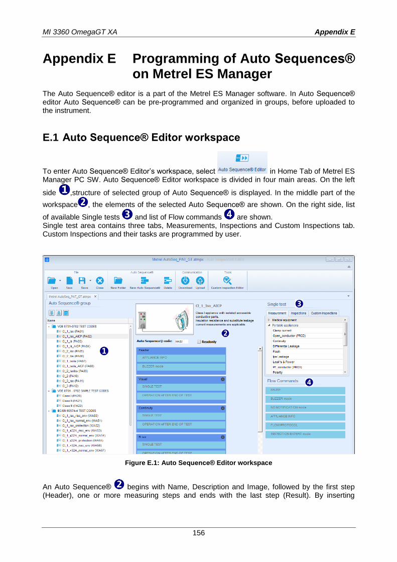
MI 3360 OmegaGT XA Appendix E
156
Appendix E Programming of Auto Sequences® on Metrel ES Manager
The Auto Sequence® editor is a part of the Metrel ES Manager software. In Auto Sequence® editor Auto Sequence® can be pre-programmed and organized in groups, before uploaded to the instrument.
E.1 Auto Sequence® Editor workspace
To enter Auto Sequence® Editor’s workspace, select in Home Tab of Metrel ES Manager PC SW. Auto Sequence® Editor workspace is divided in four main areas. On the left
side ,structure of selected group of Auto Sequence® is displayed. In the middle part of the
workspace , the elements of the selected Auto Sequence® are shown. On the right side, list
of available Single tests and list of Flow commands are shown. Single test area contains three tabs, Measurements, Inspections and Custom Inspections tab. Custom Inspections and their tasks are programmed by user.
Figure E.1: Auto Sequence® Editor workspace
An Auto Sequence® begins with Name, Description and Image, followed by the first step (Header), one or more measuring steps and ends with the last step (Result). By inserting
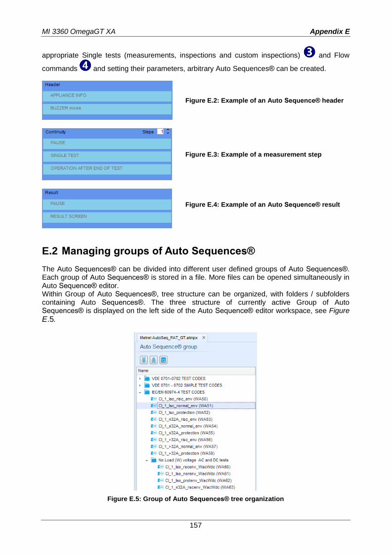
MI 3360 OmegaGT XA Appendix E
157
appropriate Single tests (measurements, inspections and custom inspections) and Flow
commands and setting their parameters, arbitrary Auto Sequences® can be created.
Figure E.2: Example of an Auto Sequence® header
Figure E.3: Example of a measurement step
Figure E.4: Example of an Auto Sequence® result
E.2 Managing groups of Auto Sequences®
The Auto Sequences® can be divided into different user defined groups of Auto Sequences®. Each group of Auto Sequences® is stored in a file. More files can be opened simultaneously in Auto Sequence® editor. Within Group of Auto Sequences®, tree structure can be organized, with folders / subfolders containing Auto Sequences®. The three structure of currently active Group of Auto Sequences® is displayed on the left side of the Auto Sequence® editor workspace, see Figure E.5.
Figure E.5: Group of Auto Sequences® tree organization
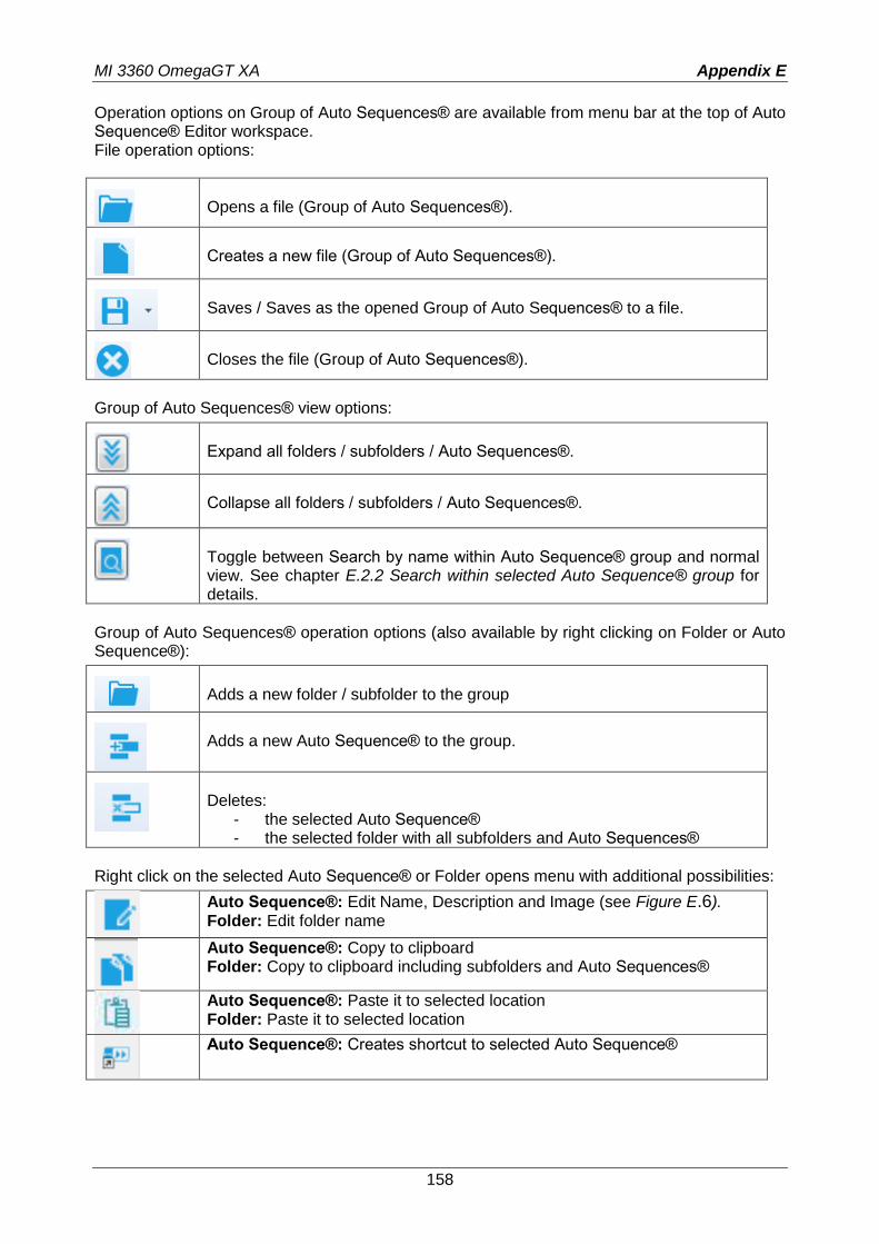
MI 3360 OmegaGT XA Appendix E
158
Operation options on Group of Auto Sequences® are available from menu bar at the top of Auto Sequence® Editor workspace. File operation options:
Opens a file (Group of Auto Sequences®).
Creates a new file (Group of Auto Sequences®).
Saves / Saves as the opened Group of Auto Sequences® to a file.
Closes the file (Group of Auto Sequences®).
Group of Auto Sequences® view options:
Expand all folders / subfolders / Auto Sequences®.
Collapse all folders / subfolders / Auto Sequences®.
Toggle between Search by name within Auto Sequence® group and normal view. See chapter E.2.2 Search within selected Auto Sequence® group for details.
Group of Auto Sequences® operation options (also available by right clicking on Folder or Auto Sequence®):
Adds a new folder / subfolder to the group
Adds a new Auto Sequence® to the group.
Deletes:
- the selected Auto Sequence® - the selected folder with all subfolders and Auto Sequences®
Right click on the selected Auto Sequence® or Folder opens menu with additional possibilities:
Auto Sequence®: Edit Name, Description and Image (see Figure E.6). Folder: Edit folder name
Auto Sequence®: Copy to clipboard Folder: Copy to clipboard including subfolders and Auto Sequences®
Auto Sequence®: Paste it to selected location Folder: Paste it to selected location
Auto Sequence®: Creates shortcut to selected Auto Sequence®
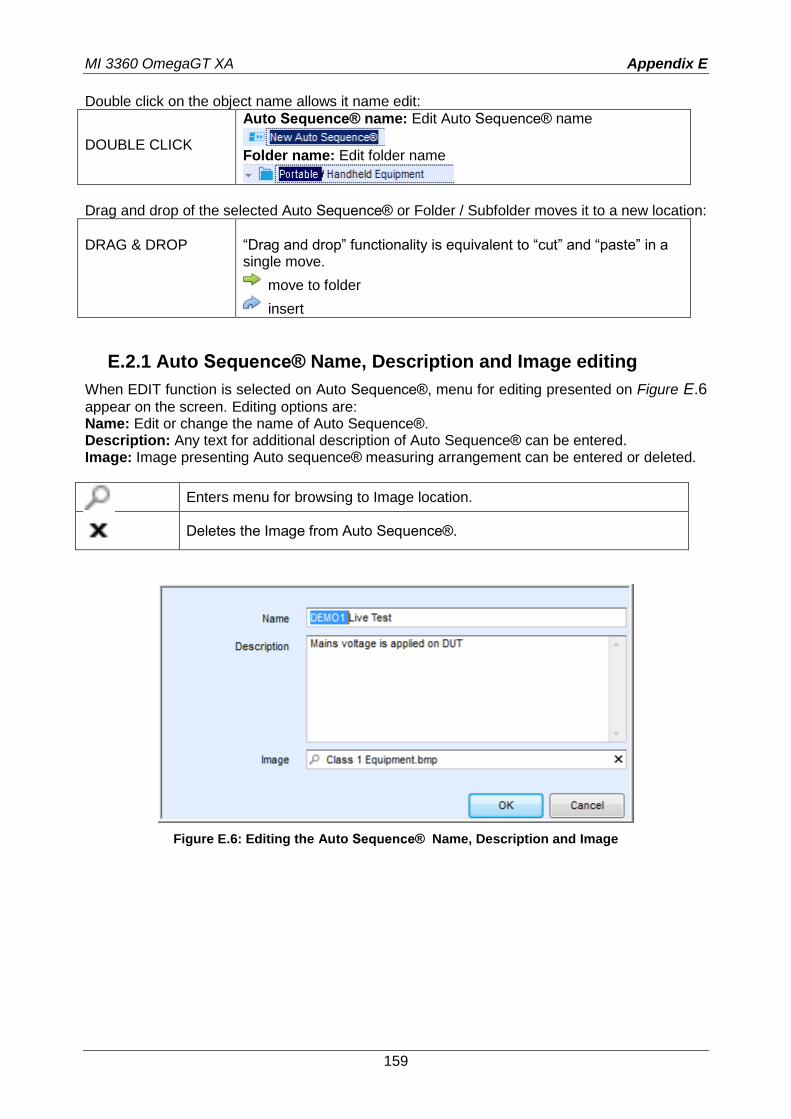
MI 3360 OmegaGT XA Appendix E
159
Double click on the object name allows it name edit:
DOUBLE CLICK
Auto Sequence® name: Edit Auto Sequence® name
Folder name: Edit folder name
Drag and drop of the selected Auto Sequence® or Folder / Subfolder moves it to a new location:
DRAG & DROP
“Drag and drop” functionality is equivalent to “cut” and “paste” in a single move.
move to folder
insert
E.2.1 Auto Sequence® Name, Description and Image editing
When EDIT function is selected on Auto Sequence®, menu for editing presented on Figure E.6
appear on the screen. Editing options are: Name: Edit or change the name of Auto Sequence®. Description: Any text for additional description of Auto Sequence® can be entered. Image: Image presenting Auto sequence® measuring arrangement can be entered or deleted.
Enters menu for browsing to Image location.
Deletes the Image from Auto Sequence®.
Figure E.6: Editing the Auto Sequence® Name, Description and Image
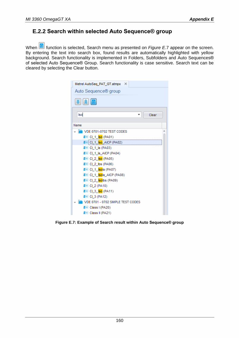
MI 3360 OmegaGT XA Appendix E
160
E.2.2 Search within selected Auto Sequence® group
When function is selected, Search menu as presented on Figure E.7 appear on the screen. By entering the text into search box, found results are automatically highlighted with yellow background. Search functionality is implemented in Folders, Subfolders and Auto Sequences® of selected Auto Sequence® Group. Search functionality is case sensitive. Search text can be cleared by selecting the Clear button.
Figure E.7: Example of Search result within Auto Sequence® group
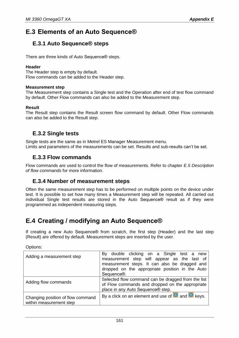
MI 3360 OmegaGT XA Appendix E
161
E.3 Elements of an Auto Sequence®
E.3.1 Auto Sequence® steps
There are three kinds of Auto Sequence® steps. Header The Header step is empty by default. Flow commands can be added to the Header step. Measurement step The Measurement step contains a Single test and the Operation after end of test flow command by default. Other Flow commands can also be added to the Measurement step. Result The Result step contains the Result screen flow command by default. Other Flow commands can also be added to the Result step.
E.3.2 Single tests
Single tests are the same as in Metrel ES Manager Measurement menu. Limits and parameters of the measurements can be set. Results and sub-results can’t be set.
E.3.3 Flow commands
Flow commands are used to control the flow of measurements. Refer to chapter E.5 Description of flow commands for more information.
E.3.4 Number of measurement steps
Often the same measurement step has to be performed on multiple points on the device under test. It is possible to set how many times a Measurement step will be repeated. All carried out individual Single test results are stored in the Auto Sequence® result as if they were programmed as independent measuring steps.
E.4 Creating / modifying an Auto Sequence®
If creating a new Auto Sequence® from scratch, the first step (Header) and the last step (Result) are offered by default. Measurement steps are inserted by the user. Options:
Adding a measurement step By double clicking on a Single test a new measurement step will appear as the last of measurement steps. It can also be dragged and dropped on the appropriate position in the Auto Sequence®.
Adding flow commands Selected flow command can be dragged from the list of Flow commands and dropped on the appropriate place in any Auto Sequence® step.
Changing position of flow command within measurement step
By a click on an element and use of and keys.
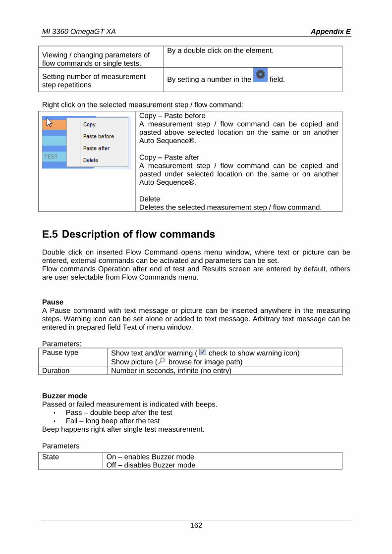
MI 3360 OmegaGT XA Appendix E
162
Viewing / changing parameters of flow commands or single tests.
By a double click on the element.
Setting number of measurement step repetitions
By setting a number in the field.
Right click on the selected measurement step / flow command:
Copy – Paste before A measurement step / flow command can be copied and pasted above selected location on the same or on another Auto Sequence®. Copy – Paste after A measurement step / flow command can be copied and pasted under selected location on the same or on another Auto Sequence®. Delete Deletes the selected measurement step / flow command.
E.5 Description of flow commands
Double click on inserted Flow Command opens menu window, where text or picture can be entered, external commands can be activated and parameters can be set. Flow commands Operation after end of test and Results screen are entered by default, others are user selectable from Flow Commands menu. Pause A Pause command with text message or picture can be inserted anywhere in the measuring steps. Warning icon can be set alone or added to text message. Arbitrary text message can be entered in prepared field Text of menu window. Parameters:
Pause type Show text and/or warning ( check to show warning icon)
Show picture ( browse for image path)
Duration Number in seconds, infinite (no entry)
Buzzer mode Passed or failed measurement is indicated with beeps.
Pass – double beep after the test Fail – long beep after the test
Beep happens right after single test measurement. Parameters
State On – enables Buzzer mode Off – disables Buzzer mode
MI 3360 OmegaGT XA Appendix E
163
No notifications mode Instrument skips pre-test warnings (see chapter 4.5 Symbols and messages for more information). Parameters
State On – enables No notifications mode Off – disables No notifications mode
Appliance info Instrument enables to automatically select the appliance type and add the Appliance ID, Appliance name and Retest period to the Auto Sequence®. Parameters
Repeat Setting Repeat: The same Appliance ID will be offered each time if the same Auto Sequence® is carried out successively in a loop.
Increment: A four digit number will be added to the Appliance ID and incremented each time if the same Auto Sequence® is carried out successively in a loop.
Appliance type Selects the type of the appliance (Appliance, Appliance_FD, Medical Equip., Medical Equip. FD, Welding Equip., Welding Equip. FD)
Default Appliance ID Enter default Appliance ID
Appliance name Enter Appliance name. Options:
Editable – allows Appliance name to be modified while running Auto Sequence®. Menu with a list of Appliance names and possibility to enter custom Appliance name is offered within the test.
Not editable – Default Appliance name is used. Appliance name cannot be modified while running Auto Sequence®.
Retest period Retest period in months. Options:
Editable – allows Retest period to be modified while running Auto Sequence®. Numeric keypad for entering custom Retest period is offered within the test.
Not editable – Default Retest period is used. Retest period cannot be modified while running Auto Sequence®.
Note
This flow command is active only if Auto Sequence® is started from the Auto Sequence® Main menu.
Inspection Expert mode If Inspection Expert mode flow command is set, the Visual inspection screen and Functional inspection screen within Auto Sequence® are displayed for 1 second and an overall PASS is automatically applied at the end of test. In between, the automatic procedure can be stopped and statuses can be applied manually. Inspection Expert mode is disabled by default. Parameters
MI 3360 OmegaGT XA Appendix E
164
State On – enables automatic settings of tickers in Visual and Functional tests. Off – disables automatic settings of tickers in Visual and Functional tests.
Operation after end of test This flow command controls the proceeding of the Auto Sequence® in regard to the measurement results. Parameters
Operation after end of test – pass – fail – no status
The operation can be individually set for the case the measurement passed, failed or ended without a status.
Manual: The test sequence stops and waits for appropriate command (RUN key, external command...) to proceed.
Auto: The test sequence automatically proceeds.
Result screen This flow commands control the proceeding after the Auto Sequence® has ended. Parameters
Auto Save Auto Sequence® results are stored in the momentary workspace. A new Node with the date and time will be created. Under the Node Auto Sequence® results or (if Appliance info flow command is set) a new appliance and Auto Sequence® results will be stored. Up to 100 Auto Sequence® results or appliances can be automatically stored under the same node. If more results / appliances are available, they are split to multiple nodes. Local Save Flow setting is disabled by default. Note
This flow command is active only if Auto Sequence® is started from the Auto Sequence® Main menu (not from the Memory organizer).
Auto Print Auto Sequence® results are automatically printed. If multiple print options are possible Print label menu is opened before printing, Note
This flow command is active only if Auto Sequence® is started from the Auto Sequence® Main menu (not from the Memory organizer).
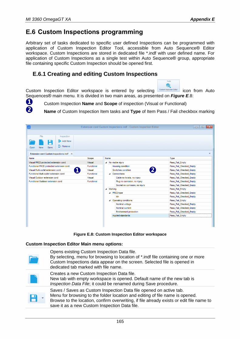
MI 3360 OmegaGT XA Appendix E
165
E.6 Custom Inspections programming
Arbitrary set of tasks dedicated to specific user defined Inspections can be programmed with application of Custom Inspection Editor Tool, accessible from Auto Sequence® Editor workspace. Custom Inspections are stored in dedicated file *.indf with user defined name. For application of Custom Inspections as a single test within Auto Sequence® group, appropriate file containing specific Custom Inspection should be opened first.
E.6.1 Creating and editing Custom Inspections
Custom Inspection Editor workspace is entered by selecting icon from Auto Sequences® main menu. It is divided in two main areas, as presented on Figure E.8:
Custom Inspection Name and Scope of inspection (Visual or Functional)
Name of Custom Inspection Item tasks and Type of Item Pass / Fail checkbox marking
Figure E.8: Custom Inspection Editor workspace
Custom Inspection Editor Main menu options:
Opens existing Custom Inspection Data file. By selecting, menu for browsing to location of *.indf file containing one or more Custom Inspections data appear on the screen. Selected file is opened in dedicated tab marked with file name.
Creates a new Custom Inspection Data file. New tab with empty workspace is opened. Default name of the new tab is Inspection Data File; it could be renamed during Save procedure.
Saves / Saves as Custom Inspection Data file opened on active tab. Menu for browsing to the folder location and editing of file name is opened. Browse to the location, confirm overwriting, if file already exists or edit file name to save it as a new Custom Inspection Data file.
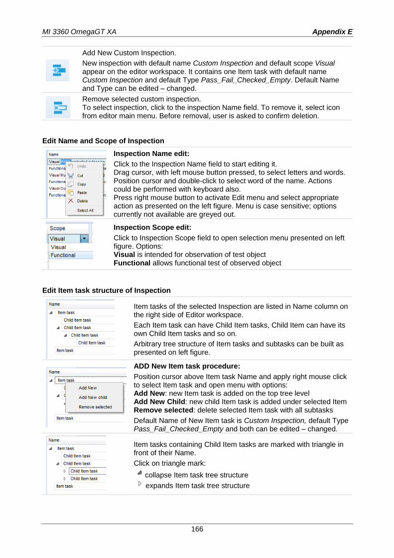
MI 3360 OmegaGT XA Appendix E
166
Add New Custom Inspection.
New inspection with default name Custom Inspection and default scope Visual appear on the editor workspace. It contains one Item task with default name Custom Inspection and default Type Pass_Fail_Checked_Empty. Default Name and Type can be edited – changed.
Remove selected custom inspection. To select inspection, click to the inspection Name field. To remove it, select icon from editor main menu. Before removal, user is asked to confirm deletion.
Edit Name and Scope of Inspection
Inspection Name edit:
Click to the Inspection Name field to start editing it. Drag cursor, with left mouse button pressed, to select letters and words. Position cursor and double-click to select word of the name. Actions could be performed with keyboard also. Press right mouse button to activate Edit menu and select appropriate action as presented on the left figure. Menu is case sensitive; options currently not available are greyed out.
Inspection Scope edit:
Click to Inspection Scope field to open selection menu presented on left figure. Options: Visual is intended for observation of test object Functional allows functional test of observed object
Edit Item task structure of Inspection
Item tasks of the selected Inspection are listed in Name column on the right side of Editor workspace.
Each Item task can have Child Item tasks, Child Item can have its own Child Item tasks and so on.
Arbitrary tree structure of Item tasks and subtasks can be built as presented on left figure.
ADD New Item task procedure:
Position cursor above Item task Name and apply right mouse click to select Item task and open menu with options: Add New: new Item task is added on the top tree level Add New Child: new child Item task is added under selected Item Remove selected: delete selected Item task with all subtasks
Default Name of New Item task is Custom Inspection, default Type Pass_Fail_Checked_Empty and both can be edited – changed.
Item tasks containing Child Item tasks are marked with triangle in front of their Name.
Click on triangle mark:
collapse Item task tree structure
expands Item task tree structure
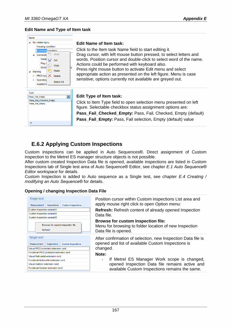
MI 3360 OmegaGT XA Appendix E
167
Edit Name and Type of Item task
Edit Name of Item task:
Click to the Item task Name field to start editing it. Drag cursor, with left mouse button pressed, to select letters and words. Position cursor and double-click to select word of the name. Actions could be performed with keyboard also. Press right mouse button to activate Edit menu and select appropriate action as presented on the left figure. Menu is case sensitive; options currently not available are greyed out.
Edit Type of Item task:
Click to Item Type field to open selection menu presented on left figure. Selectable checkbox status assignment options are:
Pass_Fail_Checked_Empty: Pass, Fail, Checked, Empty (default)
Pass_Fail_Empty: Pass, Fail selection, Empty (default) value
E.6.2 Applying Custom Inspections
Custom inspections can be applied in Auto Sequences®. Direct assignment of Custom inspection to the Metrel ES manager structure objects is not possible. After custom created Inspection Data file is opened, available inspections are listed in Custom Inspections tab of Single test area of Auto Sequence® Editor, see chapter E.1 Auto Sequence® Editor workspace for details. Custom Inspection is added to Auto sequence as a Single test, see chapter E.4 Creating / modifying an Auto Sequence® for details.
Opening / changing Inspection Data File
Position cursor within Custom inspections List area and apply mouse right click to open Option menu:
Refresh: Refresh content of already opened Inspection Data file.
Browse for custom Inspection file: Menu for browsing to folder location of new Inspection Data file is opened.
After confirmation of selection, new Inspection Data file is opened and list of available Custom Inspections is changed.
Note: If Metrel ES Manager Work scope is changed,
opened Inspection Data file remains active and available Custom Inspections remains the same.
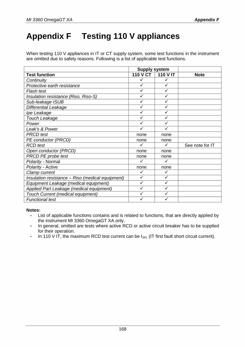
MI 3360 OmegaGT XA Appendix F
168
Appendix F Testing 110 V appliances
When testing 110 V appliances in IT or CT supply system, some test functions in the instrument are omitted due to safety reasons. Following is a list of applicable test functions.
Supply system
Test function 110 V CT 110 V IT Note
Continuity
Protective earth resistance
Flash test
Insulation resistance (Riso, Riso-S)
Sub-leakage ISUB
Differential Leakage
Ipe Leakage
Touch Leakage
Power
Leak's & Power
PRCD test none none
PE conductor (PRCD) none none
RCD test See note for IT
Open conductor (PRCD) none none
PRCD PE probe test none none
Polarity - Normal
Polarity - Active none none
Clamp current
Insulation resistance – Riso (medical equipment)
Equipment Leakage (medical equipment)
Applied Part Leakage (medical equipment)
Touch Current (medical equipment)
Functional test
Notes:
List of applicable functions contains and is related to functions, that are directly applied by the instrument MI 3360 OmegaGT XA only.
In general, omitted are tests where active RCD or active circuit breaker has to be supplied for their operation.
In 110 V IT, the maximum RCD test current can be ISFL (IT first fault short circuit current).