Embed Size (px)
Citation preview

Omega3 System
Operative Technique
•Hip Fracture•Axially Stable Locking Option
Compression Hip Screw

3
Omega3 Compression Hip Screw Operative Technique
Introduction 4Potential Features & Benefits 5Relative Indications & Contraindications 7Preoperative Planning 8Patient Positioning 9Skin Incision 10Guide Pin Insertion 11Guide Pin Measurement 14Anti-Rotation Guide Pin Insertion 15Combination Reamer Assembly Instructions 16Femoral Head / Neck Reaming 17Tapping for Lag Screw 18One-Step Lag Screw and Hip Plate InsertionInstrument Assembly Instructions 19Omega3 Hip Plate Fixation withStandard Cortical Screws 21Omega3 Hip Plate Fixation withAxial Stable Locking Screws 22Extraction of Locking Inserts 27Alternative: Lag Screw and Hip Plate Insertion 28Fracture Compression 31Closing the Wound 32Implant Removal 32
Ordering Information
Cases and Trays 33Instruments 33Optional Instruments 35Omega3 Keyed Hip-Plates 36Omega3 Keyless Hip-Plates 37Lag Screws 38Cortical Screws Ø4.5mm 39Locking Screws Ø5.0mm and Locking Insert 39Cancellous Screws Ø6.5mm 40Asnis III Screws Ø6.5mm 40
Contents

4
Introduction
The Omega3 CompressionHip Screw is a unique and innovativesystem reflecting the long experience ofStryker Trauma in the treatment of hipfractures.
This modular system offers the surgeona wide choice of slimlined hip platescombined with a unique option ofcephalic implants and state of the artinstrumentation.
The system provides a simple and easy-to-use solution for surgeons facing hipfractures.
The Omega3 Hip Fracture Systemdenotes the new locking techniquefor the hip plate shaft holes.Only the Omega3 Hip Plates offer thepossibility to apply 5.0mm LockingInserts and Locking Screws in the platediaphysis as well as standard 4.5mmCortical Screws, 6.5mm CancellousScrews and Asnis III CannulatedScrews.
The set includes lockinginstrumentation to apply and remove5.0mm Locking Inserts and LockingScrews to the Omega3 Hip Plate.

Omega3Low Profile Hip Plate
Potential Features & Benefits
• Available in both standard barrel(38mm) and short barrel (25mm)styles and a full range of sizesand angles.
• Hip plate barrel accepts theOmega Plus lag screws.
• In addition to 4.5mm cortical screws,the proximal hole of all sideplatesaccept 6.5mm cancellous screws orAsnis III 6.5mm cannulated screws foradditional stabilization.
• The hip plate allows for 5.0mmlocking inserts used in combinationwith 5.0mm locking screws forangular stable fixation.(Bi-directional shaft holes increasethe fixed angled construct.)Innovative locking screws are guidedinto the plate, thus reducing thepotential for cross-threading andcoldwelding.
• Tapered plate allows for easierinsertion when used in minimalinvasive technique with short incision.
5
Omega3Lag Screw Options13mm Standard Lag Screw
• Leading edge of the cutting threadengages quickly, with or withouttapping, and provides tactile controlduring final positioning.
15mm Super Lag Screw
• Provides excellent resistanceto migration in case ofosteoporotic bone.
Locking Screw
Locking Insert

6
State of the Art Instrumentation
Potential Features & Benefits
Fig. 1
Fig. 4Fig. 3Fig. 2
Accurate angle guides:
• Radiolucency (Fig. 1) of the angleguide body to precisely positionthe instrument, and therefore theguide pin.
• Multiple guide pin holes (Fig. 2) foraccurate placement of the guide pinwithout need to move the instrument.
• Variable Angle Guide (Fig. 3) with“freehand” technique option.
• Stiff CoCr Ø2.8mm guide pin(Fig. 4) for reduced deflection.Available also with quick couplingfor increased interface betweenthe power tool and the guide pin.
• Compatibility with the Stryker AxSOSLocking Plate System.
• Layout of the trays sequencedaccording to the surgical technique.

7
The surgeon’s education, training andprofessional judgement must be reliedupon to choose the most appropriatedevice and treatment.Conditions presenting an increased riskof failure include:
• Any active or suspected latentinfection or marked localinflammation in or about theaffected area.
• Compromised vascularity that wouldinhibit adequate blood supply to thefracture or the operative site.
• Bone stock compromised by disease,infection or prior implantation thatcannot provide adequate supportand/or fixation of the devices.
• Material sensitivity, documentedor suspected.
• Obesity: An obese patient can produceloads on the implant that can lead tofailure of the fixation of the device orto failure of the device itself.
• Patients having inadequate tissuecoverage over the operative site.
• Implant utilization that wouldinterfere with anatomical structures orphysiological performance.
• Any mental or neuromusculardisorder which would create anunacceptable risk of fixation failure orcomplications in postoperative care.
• Other medical or surgical conditionswhich would preclude the potentialbenefit of surgery. Detailedinformation is included in theinstructions for use shipped withevery implant.
See package insert for a complete listof potential adverse effects andcontraindications. The surgeon mustdiscuss all relevant risks, including thefinite lifetime of the device, with thepatient, when necessary.
Caution: Bone Screws are not intendedfor screw attachment or fixation to theposterior elements (pedicles) of thecervical, thoracic or lumbar spine.
Relative Contraindications
The Omega3 System is indicated forfractures of the proximal femur whichmay include:
Relative Indications
Note:When using the Omega3Lag Screw System, if thereis rotational instability, it isrecommended that an Asnis III6.5mm cannulated screw beadded to stabilize the fracture.Please refer to page 15 (Fig. 21).
• Intertrochanteric fracturesand subtrochanteric fractures
Relative Indications & Contraindications
• Intracapsular andbasal neck fractures
Note:When treating subtrochantericfractures with Omega3 HipPlates, the length of the hipplate has to be chosen accordingto the fracture situation. Anintramedullary device like theGamma3 Long Nail may be anoption for the treatment ofsubtrochanteric fractures.

Operative Technique
Preoperative PlanningReview the frontal and lateral X-Rays ofthe pelvis and injured femur prior tosurgery to assess fracture stability, bonequality, as well as neck-shaft angle andto estimate plate length required.
Tip: Use templates (Fig. 5)preoperatively to plan plate angle,plate length, barrel length, and lagscrew length.
The lag screw should be centeredin the head on both anterior-posteriorand lateral views, within 10 millimetersof subchondral bone. Applicationof the template to an X-Ray of theuninvolved hip may help simulatereduction of the fractured hip.
8
Preoperative X-Ray Templates for Omega3 SystemREF Description:
981120 Omega3 X-Ray Template Lag Screw 130 deg.981121 Omega3 X-Ray Template Lag Screw 135 deg.981122 Omega3 X-Ray Template Lag Screw 140 deg.981123 Omega3 X-Ray Template Lag Screw 145 deg.981124 Omega3 X-Ray Template Lag Screw 150 deg.981130 Omega3 X-Ray Template Supracondylar Plate 95 deg.
982906 Omega3 X-Ray Template Folder, empty(Note: for the storage of the above mentioned X-Ray templates)
Fig. 5

Abduction
Internal rotation
Traction
9
Patient PositioningThe patient is placed supine on thefracture table with the hip extended,adducted and slightly rotated inwards,until the patella is in a position parallelto the ground.
Satisfactory access to the hip with the C-arm in the frontal and lateral planes isverified.
Operative Technique
The fracture is reduced as anatomicallyas possible by longitudinal traction,abduction and internal rotation on afracture table.
Any inferior “sagging” at the fracturesite seen on the lateral view should becorrected by elevating the fracture fromposterior, prior to fixation.
In unstable fractures, guide pins can beplaced in order to stabilize the reducedfragments.
Note: Access to the hip with the C-arm in the frontal and lateralplanes is essential for the successof the system.

A 4 to 6 cm incision is made, startingat the level of the lesser trochanter andcontinuing straight distally. Dependingon the indication, choice of plate lengthor minimal invasive technique, theskin incision may be shorter or longer(Fig. 6).
The incision is continued through thesubcutaneous tissue and tensor fascialata in line with the skin incision.
Skin Incision
Operative Technique
10
Fig. 6
4 -6cm

11
Guide Pin Insertion
Operative Technique
Orientation and placement of theguide pin is one of the most criticalsteps in this procedure.
By utilizing one or more of thefollowing visual landmarks, correctpositioning of the guide pin canbe achieved.
With the guide pin placed at a 135°angle, the pin crosses the lateral cortexat the level of the lesser trochanter(Fig. 7 & 8); at the insertion of thegluteus maximus at the posterolateraledge of the femur; or two fingerbreadths(2.5 to 3.5cm) below the crest of thegreater trochanter at the origin of thevastus lateralis.
For each 5° change in hip plate angle,the guide pin insertion point will bemoved approximately 5mm distally(for increased angle) or proximally(for decreased angle).
The fixed angle guide corresponds tothe barrel plate angle. Angles of 130°,140°, 145° or 150° may be guided usingthe variable angle guide.
In the following description of theoperative technique the most commonused 135° CCD is shown in theprocedure.
A variable angle guide (Fig. 9) inconjunction with a T-handle can beused to insert the guide pin at 130°,135°, 140°, 145° and 150°.
Note: The variable angle guide isradiolucent (Fig. 10) to facilitatecorrect positioning of the angleguide and the guide pin underimage intensifier (helpful whena reduced skin incision isperformed and direct visibilityof the site is therefore reduced).
Note: Be sure to verify that the set angleis not changed when the variableangle guide is touching softtissue. This may occur whenthe incision is made too small.
Fig. 7 Fixed Angle Guide for guide pin Placement
Fig. 9 Variable angle guide for guide pin placement orangle measurement when the guide pin isinserted in “free hand technique”
Fig. 10
135°
Lessertrochanter
Fig. 8

Guide Pin Insertion, continued
Operative Technique
Frontal view Lateral viewWhile holding the appropriate angleguide firmly on the femoral shaft,the 2.8mm guide pin is inserted in thehole of the angle guide and advancedinto the femoral head under imageintensification until it reaches thesubchondral bone in the center ofthe femoral head in both frontaland lateral views (Fig. 11 & 12).
If the guide pin is not positionedcorrectly, an additional pin can beinserted 5mm above or below thecentral position in the frontal plane,and 5mm anteriorly or posteriorly tothe central position in the lateral plane,without removing the first guide pin(Fig. 13 & 14).
Note: To insert a second pin near thefirst one, use a quick couplingchuck for 2.8mm guide pin(REF 704027) together with a2.8mm guide pin with quickcoupling fitting (REF 704012S),otherwise there is a risk that thepower drill chuck will touch thefirst guide pin.
Fig. 11 A/P View Fig. 12 Lateral View
Fig. 13 Optional: Correction of guide pin placement possible using an additional guide pin: lateral view
Fig. 14 Optional: Correction of guide pin placement possible using an additional guide pin: AP view

13
Guide Pin Insertion, continued
Operative Technique
“Freehand” technique for guide pinplacement:
Place a 2.8mm guide pin anterior tothe neck of the femur (Fig. 15) andalign it in the center of the headagainst the medial cortex by usingimage intensification.
A 3.2mm drill bit can be used to makean opening in the lateral cortex,allowing for easy insertion of the guidepin. Using image intensification, theguide pin is advanced until it reachesthe subchondral bone in the femoralhead. After confirming appropriate tipposition of the guide pin on bothfrontal and lateral views, verify theappropriate plate angle by using thevariable angle guide. To unlock themechanism, pull the cylinder of theguide (Fig. 16) and turn it by 90°(Fig. 17).
Slide the variable angle guide over theguide pin and adjust it down to thelateral aspect of the femur (make surethat all the spikes are in contact withthe bone shaft). The arrow on thecylinder will indicate at which anglethe guide pin has been inserted (Fig.18), and therefore the angle of thebarrel plate to be selected.
Note: Be sure to verify that the set angleis not changed when the variableangle guide is touching softtissue. This may occur when theincision is made too small.
Fig. 15 Guide Pin anterior to the neck of the femur
Fig. 16 Fig. 17 Fig. 18

14
Operative Technique
Example without compression:
• Depth gauge measurement: 110mm
• Reamer depth setting: 100mm
• Lag screw length selected: 100mm
Example with 5mm compression:
• Depth gauge measurement: 110mm
• Reamer depth setting: 100mm
• Desired compression: 5mm
• Lag screw length selected: 95mm
Guide Pin Measurement
The depth gauge indicates the exactlength of the guide pin which has beeninserted into the bone (Fig. 19).The surgeon must decide the depth towhich the lag screw will be inserted.
The reaming depth is recommendedto be approximately 10mm shorter thanthe depth gauge reading to permit thecorrect tip-apex distance.
How to select the correct length of thelag screw when applying compression:
The fracture must first be reducedanatomically. Compression may enhancethe reduction but does not replace it.
Intra-operatively, once the femoral neckchannel has been reamed, the surgeonmust use image intensification to judgethe amount of compression required.
The compression is limited by thelength of the compression screw threads(10mm) and also by the length of thelag screw chosen. The lag screw must beshorter than the reamed channel by thenumber of millimeters of compressionrequired.
If, following the compression, asurgeon sees on the X-Ray that furthercompression is necessary but impossibledue to the length of the implant andcompression screw, he must remove theimplant and choose a shorter length lagscrew.Any attempt to force compressioncan result in breakage of thecompression screw.
Fig. 19

15
This step is especially useful inproviding temporary stability forfemoral neck fractures and basal neckfractures, where the head could rotateduring reaming or screw insertion.
Correct positioning of theanti-rotational wire can be doneby rotating the instrument anteriorly orposteriorly (Fig. 20).
This instrument also accommodatesa 3.2mm guide wire, should the surgeonwish to insert a 6.5mmAsnis III cannulated screw for definitiverotational stability(Fig. 21).
The guide pin replacement instrumentcan also be used to insert a secondguide pin parallel to the primary guidepin, depending on the fracture pattern(Fig. 20).
The guide pin for the lag screw must beplaced in an inferior position to allowspace for placement of a second pin orscrew, if the femoral neck is narrow.
Anti-Rotation Guide Pin Insertion
Operative Technique
Diam. 2.8mm hole
Diam. 3.2mm hole
Fig. 20
Fig. 21
16
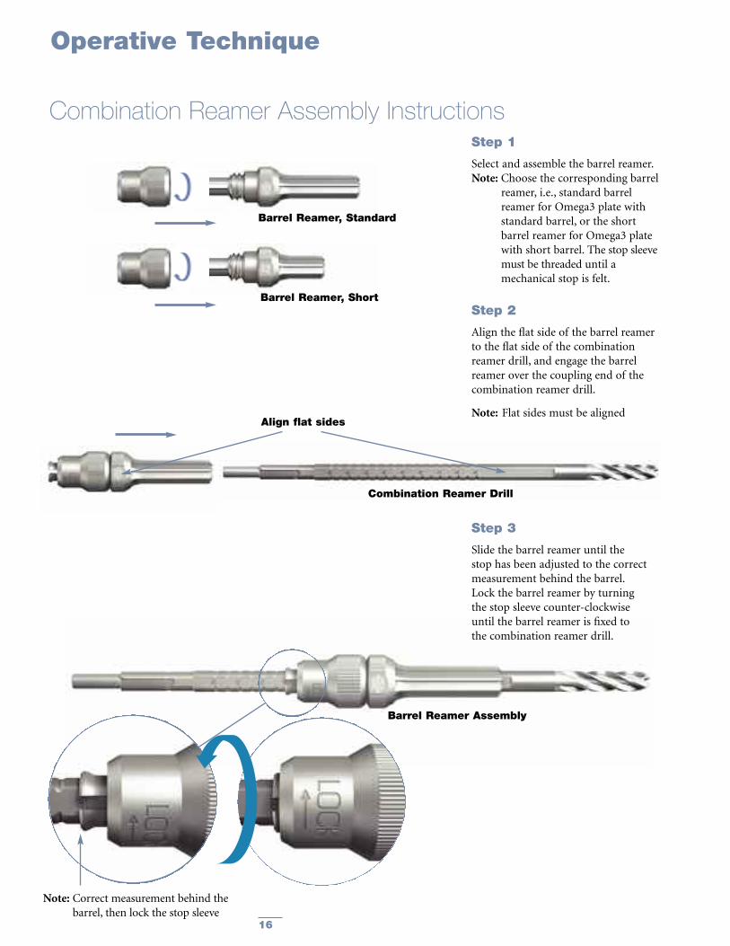
Combination Reamer Drill
Step 2
Align the flat side of the barrel reamerto the flat side of the combinationreamer drill, and engage the barrelreamer over the coupling end of thecombination reamer drill.
Note: Flat sides must be aligned
Barrel Reamer, Standard
Step 3
Slide the barrel reamer until thestop has been adjusted to the correctmeasurement behind the barrel.Lock the barrel reamer by turningthe stop sleeve counter-clockwiseuntil the barrel reamer is fixed tothe combination reamer drill.
Barrel Reamer Assembly
Combination Reamer Assembly Instructions
Operative Technique
Barrel Reamer, Short
Step 1
Select and assemble the barrel reamer.Note: Choose the corresponding barrel
reamer, i.e., standard barrelreamer for Omega3 plate withstandard barrel, or the shortbarrel reamer for Omega3 platewith short barrel. The stop sleevemust be threaded until amechanical stop is felt.
Note: Correct measurement behind thebarrel, then lock the stop sleeve
Align flat sides

17
Operative Technique
Femoral Head / Neck ReamingSelect and assemble the correct barrelreamer (according to the standard orshort barrel plate selected).
The combination reamer is setand locked by firmly turning thestop sleeve counter-clockwise atthe predetermined depth setting(approximately 10mm less thanthe guide pin measurement).
Ream over the guide pin with thecombination reamer until the stopreaches the lateral cortex (Fig. 22).
Remove the combination reamer whilestill reaming clockwise, in order toremove debris from the reamed canal.
Note: Guide pins are not intendedfor re-use.They are for single use only.Guide pins may be damaged orbent during surgical procedures.If a guide pin is re-used, it maybecome lodged in the drill andcould be advanced into thepelvis, damaging large bloodvessels or vital organs.
Should the guide pin be inadvertentlywithdrawn, reverse the guide pinreplacement instrument (Fig. 23),insert it into the femur, and reinsertthe guide pin(Fig. 24).
Note for short barrel plates:
For more lateral intertrochantericfractures or medial displacementosteotomies, the short barrel platesprovide fixation without the barrelcrossing the fracture.
Reaming is accomplished using theshort barrel reamer, following thesame procedure for standard barrelreaming.
Fig. 22
Fig. 23
Fig. 24

18
The lag screw tap should be usedwhen good quality, dense bone isencountered; the calibrated tap sleeveindicates the proper depth of the tap.
The tap is advanced until the indicatorring on the tap reaches the correctdepth marking on the centering sleeve(Fig. 25).
Note: If significant torque is required totap very dense bone, considerationshould be givento placing an antirotationguide-wire.
Example:
• Depth gauge measurement: 110mm
• Reamer depth setting: 100mm
• Tapping depth: 100mm
• Lag screw length selected: 100mm
Tapping for Lag Screw
Operative Technique
Lag Screw Tap Assembly
Calibrated Tap SleeveLag Screw Tap
Push the quick coupling sleeve on thelarge T-handle and insert the lag screwtap fitting into the coupling.
Assemble the lag screw tap sleeve to thelag screw tap by aligning the flat sides ofthe tap to the flat sides in the tap sleeve.
Fig. 25

19
Operative Technique
One-Step Lag Screw and Hip Plate Insertion
Prior to assembling the one-stepinsertion sleeve to the one-step insertionwrench/hip plate assembly, ensure thatthe one-step insertion sleeve is opened(mark on the inner sleeve lining up withthe “open”mark on the outer sleeve).
Assemble the one-step insertion sleeveto the one-step insertion wrenchbetween the hip plate and the lag screw,and lock the one-step insertion sleeve.
To lock the one-step insertion sleeve,the inner and outer sleeve are twistedin opposite directions until the markon the inner sleeve lines up with the“close” mark on the outer sleeve.
To unlock the sleeve, align the markwith the “open” mark on the outersleeve.
Instrument Assembly InstructionsAssemble the large T-handleto the one-step insertion wrenchas described in instruction below.Slide the one-step insertion wrenchthrough the barrel of the hip plate.
Lag ScrewConnecting Bolt
The connecting bolt is inserted throughthe large T-handle and threaded intothe lag screw.
One-Step InsertionWrench
Omega3 Hip Plate
One-Step Insertion Sleeve

20
One-Step Insertion Option, continued
Operative Technique
Assemble the appropriate hip plateand the lag screw onto the one-stepinsertion wrench.
For typical anatomy (135° head/neckangle), advance the one-step insertionwrench until the ring marked “135°”reaches the one-step insertion sleeve.
For valgus anatomy (150° head/neckangle), advance the one-step insertionwrench until the ring marked “150°”reaches the one-step insertion sleeve.Other angled plates should be insertedproportionally between the marks.
Place the entire assembly over the guidepin and introduce it into the reamedhole (Fig. 26).
Advance the lag screw into the proximalfemur to the predetermined depth andverify using image intensification.
At the conclusion of screw insertion,the handle of the one-step insertioninstrument must be aligned with thelong axis of the femoral shaft to allowproper keying of the lag screw to theplate barrel (Fig. 27).
Remove the one-step insertion sleeveand advance the hip plate onto the lagscrew shaft.
The plate impactor should be usedto fully seat the plate.
Unscrew the connecting bolt andremove the one-step insertion wrenchfrom the back of the lag screw; removethe 2.8mm guide pin.
Depth of the insertion of the lag screwis determined by observing the twodepth indicator rings on the one-stepinserter wrench (Fig. 28). From here theoperation is continued with either theaxial stable fixation of the hip plateusing locking inserts and locking screwsor the standard fixation with corticalscrews (See page 21).
Stop inserting the lag screw when the135° ring reaches the one-step insertion sleeve(when a 135° hip plate is selected)
Fig. 26
Fig. 27
Fig. 28

Fig. 33
21
Omega3 Hip Plate Fixation with Standard Cortical ScrewsThe Omega3 System allows fortwo alternatives of plate fixation:1. Fixation with 4.5mm cortical screws.2. Axial stable fixation with 5.0mmlocking inserts and locking screws.For axial stable fixation with lockinginserts and locking screws please referto the section on page 22. For standard4.5mm cortical screw fixation pleasefollow the steps described below.
Using standard cortical screw insertiontechnique, fix the Omega3 hip plate tothe femoral shaft beginning at theproximal end of the plate.
Note:When using the reduced skinincision technique, supplementarystab incisions can be performedfor distal screw placements.
Use the drill bit through the drill sleevewith the green ring (neutral) assembledto the drill guide handle, to drill thebone screw holes (Fig. 29).
Note: If necessary it is possible to obtaincompression of a shaft fracture orosteotomy site when using thedrill sleeve with the yellow ring(1mm compression).
Determine appropriate cortical screwlength using the depth gauge (Fig. 30).Always select a screw length one sizelonger in order to ensure the optimalbi-cortical purchase.
Insert the self tapping screw using the3.5mm hex screwdriver with T-handle(Fig. 31).
A 4.5mm tap is available, to pre-tapin extremely hard cortical bone.It is recommended to use the tap inconjunction with a sleeve, if soft tissueis close to the tap (Fig. 32).
Operative Technique
Option
Antero-lateral view of the Omega3hip plate fixed with standard corticalscrews (Fig. 33).
Fig. 29
Fig. 30
Fig. 31
Fig. 32
22
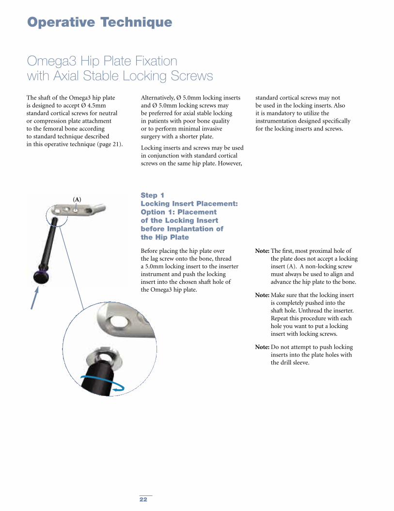
The shaft of the Omega3 hip plateis designed to accept Ø 4.5mmstandard cortical screws for neutralor compression plate attachmentto the femoral bone accordingto standard technique describedin this operative technique (page 21).
Alternatively, Ø 5.0mm locking insertsand Ø 5.0mm locking screws maybe preferred for axial stable lockingin patients with poor bone qualityor to perform minimal invasivesurgery with a shorter plate.
Locking inserts and screws may be usedin conjunction with standard corticalscrews on the same hip plate. However,
standard cortical screws may notbe used in the locking inserts. Alsoit is mandatory to utilize theinstrumentation designed specificallyfor the locking inserts and screws.
Operative Technique
Omega3 Hip Plate Fixationwith Axial Stable Locking Screws
Step 1Locking Insert Placement:Option 1: Placementof the Locking Insertbefore Implantation ofthe Hip Plate
Before placing the hip plate overthe lag screw onto the bone, threada 5.0mm locking insert to the inserterinstrument and push the lockinginsert into the chosen shaft hole ofthe Omega3 hip plate.
Note: The first, most proximal hole ofthe plate does not accept a lockinginsert (A). A non-locking screwmust always be used to align andadvance the hip plate to the bone.
Note:Make sure that the locking insertis completely pushed into theshaft hole. Unthread the inserter.Repeat this procedure with eachhole you want to put a lockinginsert with locking screws.
Note:Do not attempt to push lockinginserts into the plate holes withthe drill sleeve.
(A)

23
Option 2:Placementof the Locking Insertafter Implantationof the Hip Plate (in situ):
If desired, a locking insert can be appliedin a compression hole in the shaft of theplate intra-operatively (in situ) by usingthe locking insert forceps, holding pinand guide for holding pin.Whenchoosing this option, first implant thehip plate according to the descriptionon page 21, perform a cortical screwinsertion in the most proximal hole toadvance the plate to the bone and thencontinue as described below with thelocking inserts and locking screws.
Operative Technique
Omega3 Hip Plate Fixationwith Axial Stable Locking Screws, continued
Fig. 34
Fig. 35
Fig. 36
First, the holding pin is inserted throughthe chosen hole using the drill sleeve forholding pin (Fig. 34). It is important touse the guide as this centers the core holefor locking screw insertion after thelocking insert is applied. After insertingthe holding pin bi-cortically, remove theguide.
Next, place a locking insert on the endof the forceps and slide the instrumentover the holding pin down to the hole(Fig. 35). Finally, apply the locking insertby triggering the forceps handle.
Push the button on the forceps to removethe device (Fig. 36). At this time, removethe holding pin.

24
Operative Technique
Omega3 Hip Plate Fixation –with Axial Stable Locking Screws, continued
Step 4Drill:Drill through both cortices of thefemoral shaft using the 4.3mm drill bitattached to power (Fig. 39).
Step 3Apply Drill Sleeve:Thread the drill sleeve into the lockinginsert to expand its base within theplate hole, thus securing it (Fig. 38).
For easier alignment, first push the drillsleeve down towards the plate and thenrotate it to engage the thread.
Fig. 39
Fig. 38
Fig. 37
Step 2Cortical Screw Insertion:Perform cortical screw insertionin the first, most proximal holeaccording to the description onpage 21 (Fig. 37).

25
Operative Technique
Omega3 Hip Plate Fixationwith Axial Stable Locking Screws, continued
Step 5Screw Measurement:Measure the required screw lengthby one of the two possibilities:
Option 1:Measuring off the drill, using thecalibrations marked on the drill (Fig. 40).
Note: Always select a screw lengthone size longer than measured,in order to ensure the optimalbi-cortical purchase.
Option 2:Read directly off the direct measuringgauge through the locking insert acrossboth cortices (Fig. 41).
Note: Always select a screw length onesize longer than measured in order toensure the optimal bi-cortical purchase.
Fig. 40
Fig. 41

26
Operative Technique
Omega3 Hip Plate Fixationwith Axial Stable Locking Screws, continued
Step 6Screw Insertion:Insert the locking screw into thelocking insert, using the screw driverT20, AO fitting, the torque limiter andthe T-handle, medium. Alternativelythe screwdriver T20, AO fitting can beused under direct power. However,final tightening always must be donemanually.
The locking screw is adequetlytightened when the torque limiterclicks at least once at the endof manual tightening (Fig. 42).
Note: The torque limiter is crucialto the mechanical integrity of theconstruct.
Antero-lateral view of the Omega3 hipplate fixed with axial stable lockingscrews (Fig. 43).
“Click”
Fig. 42
Fig. 43

27
Operative Technique
Should removal of a locking insert berequired then the following procedureshould be used:
Step 1: Thread the central portion(Fig. 44) of the Extractor into thelocking insert until it is fully seated.
Step 2: Turn the outer collet (Fig. 45)clockwise until it pulls the lockinginsert out of the plate.
Step 3: Remove the locking insertfrom the extractor by threading it off.
Note:Discard the locking insertas it cannot be reused.
Extraction of Optional Locking Inserts
Fig. 44 Fig. 45

Alternative: Lag Screw and Hip Plate InsertionAs an alternative to the one-stepinsertion, the standard technique maybe used to insert the hip plate and thelag screw.
Lag Screw Instrument Assembly Instructions
Operative Technique
Lag Screw Inserter Assembly:Slide the lag screw inserter sleeve overthe lag screw inserter.
Lag Screw Adapter(Outer Part)
Lag Screw Adapter(Inner part)
Lag Screw Adapter Lag Screw
Lag Screw Adapter Assembly:Thread the inner part of the lag screwadapter through the outer part.
Thread the assembly into the lag screw.
Lag Screw Inserter Sleeve Lag Screw Adapter Assembly
28

The T-handle of the insertion/extractionwrench is aligned with the long axis ofthe femur in preparation for placementof the hip plate (Fig. 47).
Note: In this manner, the “flats” of thelag screw are in proper alignmentwith the barrel of the hip plate forthe keyed hip plate system.
Select a lag screw of the appropriatelength and assemble it to the lag screwadapter. Join the lag screw inserterassembly to the lag screw adapterassembly. Insert the lag screw intothe bone over the guide pin.
The centering sleeve on the inserterassembly is advanced into the pre-reamed hole, and the lag screw isdriven into the prepared channel.
Advance the lag screw by turning andpushing the T-handle clockwise to itsfinal position.
Depth of insertion of the lag screw isdetermined by observing the two depthindicator rings on the inserter (Fig. 46).
Operative Technique
Alternative: Lag Screw and Hip Plate Insertion, continued
Depth Indicator RingsDepth indicator rings measuredesired compression.
For typical anatomy (135° head/neckangle), advance the lag screw inserterassembly until the ring marked “135°”reaches the zero mark on the inserter.
For valgus anatomy (150° head/neckangle), advance the lag screw inserterassembly until the ring marked “150°”reaches the zero mark on the inserter.
Center the sleeve corresponding tothe amount of compression desired.
5mm Compression,in case of 135° plate
10mm Compression,in case of 135° plate
No Compression,in case of 135° plate
Fig. 46
Fig. 47
29

30
Upon completion of lag screw insertion,the lag screw inserter assembly isremoved from the lag screw by pullingback, leaving the lag screw adapter inplace.
The selected Omega3 hip plate is nowplaced over the lag screw adapter andadvanced to engage the lag screw(Fig. 48).
Impaction of the fracture maybe accomplished by using the plateimpactor together with a hammeror mallet (Fig. 49).
Note: Use gentle hammering only -otherwise the impactor may bedestroyed.
Unscrew the lag screw adapter byhand and remove it. Then, remove the2.8mm guide pin.
Note: All guide pins are for single useand therefore must be discardedat the end of the surgicalprocedure.
For further continuation of theprocedure please refer to page 21for the fixation of the hip plate withstandard cortical screws or follow theinstructions on page 22 for the axialstable fixation of the hip plate with5.0mm locking inserts and lockingscrews.
Operative Technique
Alternative: Lag Screw and Hip Plate Insertion, continued
Fig. 48
Fig. 49
31
Operative Technique
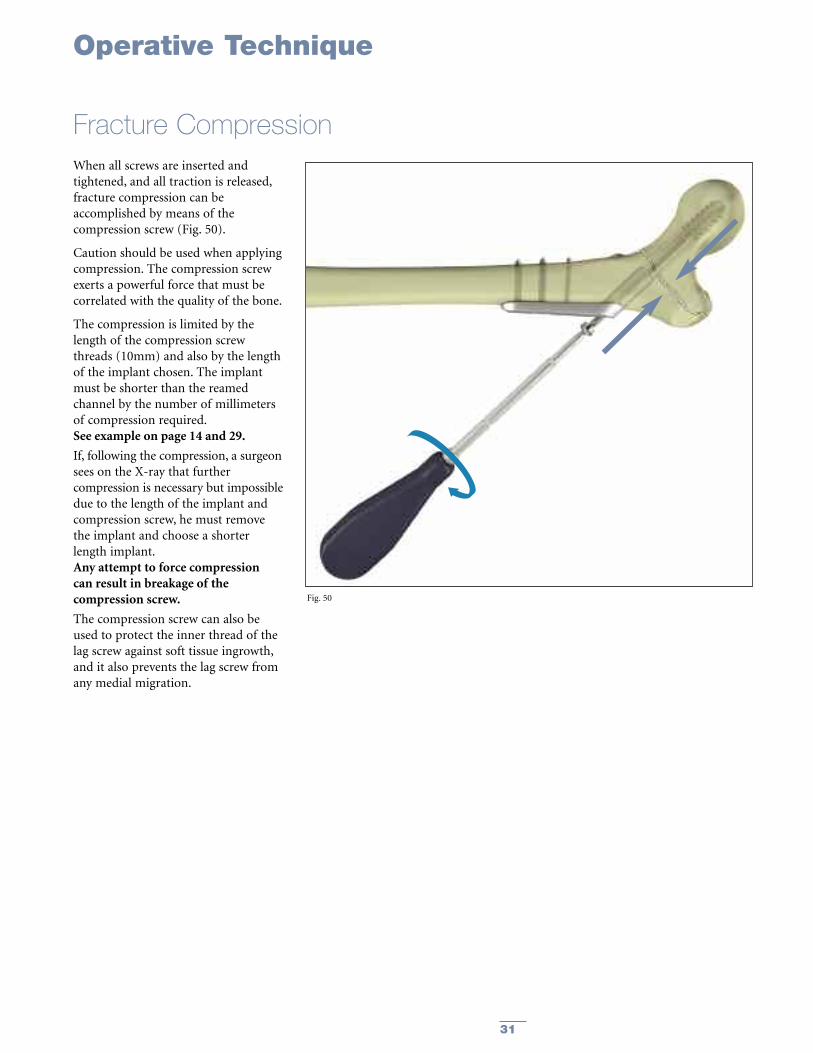
Fracture CompressionWhen all screws are inserted andtightened, and all traction is released,fracture compression can beaccomplished by means of thecompression screw (Fig. 50).
Caution should be used when applyingcompression. The compression screwexerts a powerful force that must becorrelated with the quality of the bone.
The compression is limited by thelength of the compression screwthreads (10mm) and also by the lengthof the implant chosen. The implantmust be shorter than the reamedchannel by the number of millimetersof compression required.See example on page 14 and 29.
If, following the compression, a surgeonsees on the X-ray that furthercompression is necessary but impossibledue to the length of the implant andcompression screw, he must removethe implant and choose a shorterlength implant.Any attempt to force compressioncan result in breakage of thecompression screw.
The compression screw can also beused to protect the inner thread of thelag screw against soft tissue ingrowth,and it also prevents the lag screw fromany medial migration.
Fig. 50

32
Closing the Wound
Implant Removal
The connecting bolt is insertedthrough the lag screw inserter andthreaded into the lag screw.
Lag Screw Removal Assembly
Lag ScrewConnecting Bolt Lag Screw Inserter
Operative Technique
Closure of the wound is done inlayers, closing separately the fasciaof the vastus lateralis muscle andthe facia lata. Carefully reapproximatethe subcutaneous tissue and the skin(Fig. 51).
Should the need arise for hardwareremoval, the lag screw is extractedafter removal of the hip plate throughuse of the large T-handle connectedto the lag screw inserter and theconnecting bolt.The T-handle is turned counter-clockwise (Fig. 52).
Note: A guide wire can be placed intothe screw to aid in alignment ofthe T-handle.
Fig. 51
Fig. 52

33
Ordering Information
REF Description
Kits
990226 Omega 3 Instrument Set Complete990225 Omega 3 Instrument Set “Light”
Cases and Trays
902035 Omega3 Metal Case, empty901745 Omega3 Lower Tray, empty902036 Omega3 Upper Tray, empty902037 Omega3 Screw Rack, empty902039 Omega3 Metal Case Lid902114 Omega3 Silicone Mat
Instruments
700358 Drill Bit Ø 3.2mm x 145mm
700359 Drill Bit Ø 4.5mm x 145mm
702402 Tissue Protection Sleeve
702430 Elastosil T-Handle, Medium
702844 Screwdriver Hex 3.5mm
702672 Drill Sleeve for Holding Pin, ø4.9mm, 5.0mm Locking Set
702674 Holding Pin, Ø4.3mm, 5.0mm Locking Set
702708 Drill Sleeve, 5.0mm Locking Set
702743 Calibrated Drill Bit, Ø4.3mm x 262mm, 5.0mm Locking Set, AO Fitting
702751 Universal Torque Limiter, 5.0mm Locking Set, AO Fitting
702754 Screwdriver T20, 5.0mm Locking Set, AO Fitting
702763 Locking Insert Inserter, 5.0mm Locking Set
702768 Locking Insert Extractor, 5.0mm Locking Set
702808 Tap Ø4.5mm x 145mm, AO Fitting
702809 Tap Ø6.5mm x 145mm, AO Fitting
702822 Drill Guide Handle
702840 Drill Sleeve Ø 3.2mm, Neutral
702853 Screwdriver Hex 3.5mm, AO Fitting
702878 Depth Gauge Assembly
702884 Direct Depth Gauge, 5.0mm Locking Set
702969 Locking Insert Forceps, 5.0mm Locking Set
704001 Plate Impactor Assembly

34
Ordering Information
REF Description
704003 One-Step Insertion Sleeve
704004 Connecting Bolt, Cannulated
704010 Lag Screw Depth Gauge
704013 Fixed Angle Guide 135º
704014 Variable Angle Guide, Modular
704019 Guide Pin Replacement Instrument
704020 Elastosil T-Handle, Large AO Fitting
704026 Cleaning Stylet, Ø 2.8mm
704027 Adapter, Guide Wire/Hall
704205 95º Angle Guide for Supracondylar Plate
704044 Combination Reamer Shaft, Hall Fitting
704046 Adapter, Small AO/Hall
704047 One Step Insertion Wrench, Non-Modular
900106 Screw Forceps
3861-3-005 Lag Screw Tap, Non-Modular
3861-3-010 Lag Screw Tap Sleeve
3861-3-026 Lag Screw Adapter
704005-20 Barrel Reamer Assembly, Standard
704006-20 Barrel Reamer Assembly, Short

35
Ordering Information
REF Description
GuideWires
704011S Guide Wire Ø 2.8mm x 230mm, CoCr, Threaded Tip, Sterile
704012S Guide Wire, Quick Coupling, Ø 2.8mm x 230mm, CoCr, Threaded Tip, Sterile
Optional Instruments
702634 Large AO to Hall Coupling
702748 Screwdriver T20, 5.0mm Locking Set
702823 Drill Sleeve Ø3.2mm, Compression
702863 Holding Sleeve for Screwdrivers
702946 Self-Centering Bone Forceps with Swivel Head, Size 3
704025 Drill Sleeve Ø 3.2mm, Supracondylar
704041 Variable Angle Guide, Non Modular
3861-3-015 Lag Screw Inserter, Non Modular
3861-3-020 Lag Screw Inserter Sleeve
702918 Soft Tissue Spreader, 5.0mm Locking Set
704002 One-Step Insertion Wrench, Modular
704001-1 Plate Impactor Head
36
Ordering Information – Implants
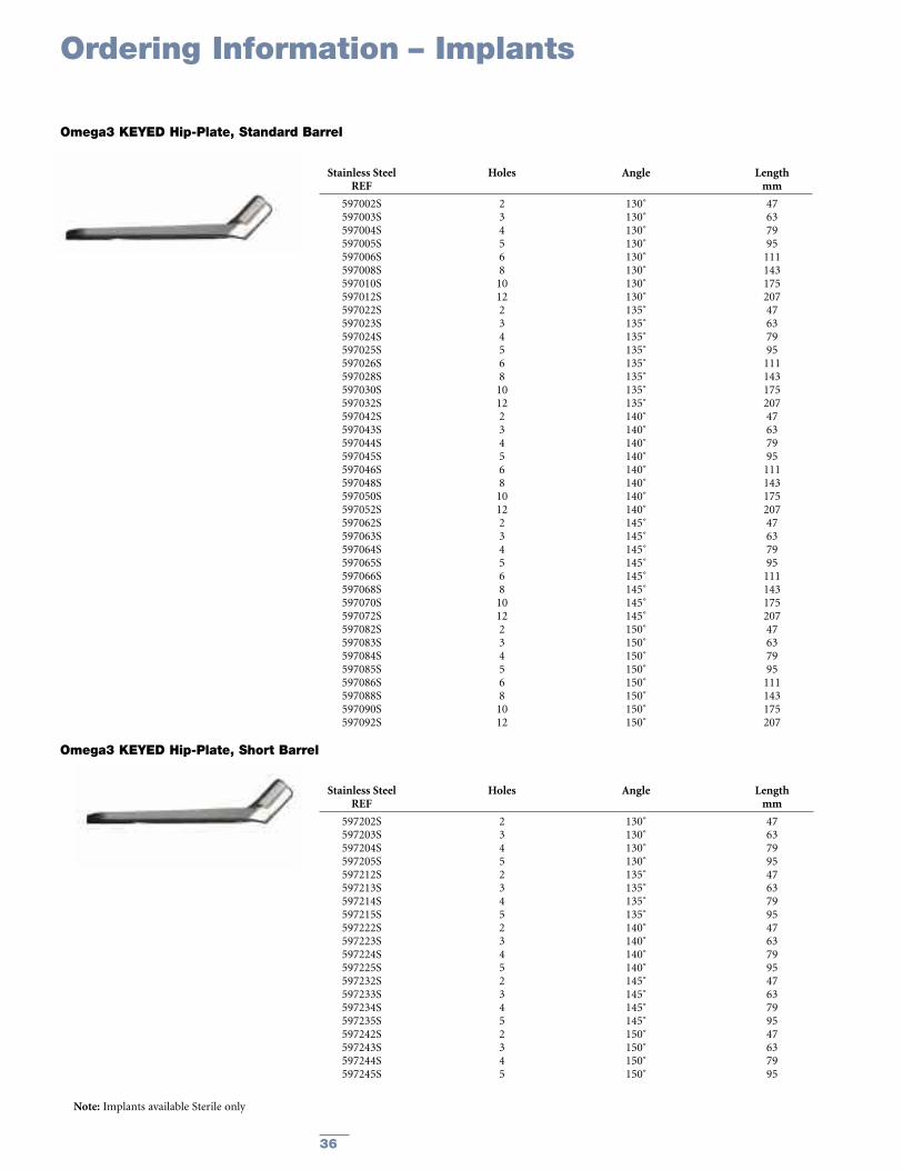
Stainless Steel Holes Angle LengthREF mm
597002S 2 130˚ 47597003S 3 130˚ 63597004S 4 130˚ 79597005S 5 130˚ 95597006S 6 130˚ 111597008S 8 130˚ 143597010S 10 130˚ 175597012S 12 130˚ 207597022S 2 135˚ 47597023S 3 135˚ 63597024S 4 135˚ 79597025S 5 135˚ 95597026S 6 135˚ 111597028S 8 135˚ 143597030S 10 135˚ 175597032S 12 135˚ 207597042S 2 140˚ 47597043S 3 140˚ 63597044S 4 140˚ 79597045S 5 140˚ 95597046S 6 140˚ 111597048S 8 140˚ 143597050S 10 140˚ 175597052S 12 140˚ 207597062S 2 145˚ 47597063S 3 145˚ 63597064S 4 145˚ 79597065S 5 145˚ 95597066S 6 145˚ 111597068S 8 145˚ 143597070S 10 145˚ 175597072S 12 145˚ 207597082S 2 150˚ 47597083S 3 150˚ 63597084S 4 150˚ 79597085S 5 150˚ 95597086S 6 150˚ 111597088S 8 150˚ 143597090S 10 150˚ 175597092S 12 150˚ 207
Omega3 KEYED Hip-Plate, Standard Barrel
Stainless Steel Holes Angle LengthREF mm
597202S 2 130˚ 47597203S 3 130˚ 63597204S 4 130˚ 79597205S 5 130˚ 95597212S 2 135˚ 47597213S 3 135˚ 63597214S 4 135˚ 79597215S 5 135˚ 95597222S 2 140˚ 47597223S 3 140˚ 63597224S 4 140˚ 79597225S 5 140˚ 95597232S 2 145˚ 47597233S 3 145˚ 63597234S 4 145˚ 79597235S 5 145˚ 95597242S 2 150˚ 47597243S 3 150˚ 63597244S 4 150˚ 79597245S 5 150˚ 95
Omega3 KEYED Hip-Plate, Short Barrel
Note: Implants available Sterile only

37
Ordering Information – Implants
Stainless Steel Holes Angle LengthREF mm
597102S 2 130˚ 47597103S 3 130˚ 63597104S 4 130˚ 79597105S 5 130˚ 95597106S 6 130˚ 111597108S 8 130˚ 143597110S 10 130˚ 175597112S 12 130˚ 207597122S 2 135˚ 47597123S 3 135˚ 63597124S 4 135˚ 79597125S 5 135˚ 95597126S 6 135˚ 111597128S 8 135˚ 143597130S 10 135˚ 175597132S 12 135˚ 207597142S 2 140˚ 47597143S 3 140˚ 63597144S 4 140˚ 79597145S 5 140˚ 95597146S 6 140˚ 111597148S 8 140˚ 143597150S 10 140˚ 175597152S 12 140˚ 207597162S 2 145˚ 47597163S 3 145˚ 63597164S 4 145˚ 79597165S 5 145˚ 95597166S 6 145˚ 111597168S 8 145˚ 143597170S 10 145˚ 175597172S 12 145˚ 207597182S 2 150˚ 47597183S 3 150˚ 63597184S 4 150˚ 79597185S 5 150˚ 95597186S 6 150˚ 111597188S 8 150˚ 143597190S 10 150˚ 175597192S 12 150˚ 207
Omega3 KEYLESS Hip-Plate, Standard Barrel
Stainless Steel Holes Angle LengthREF mm
597254S 4 130˚ 79597255S 5 130˚ 95597264S 4 135˚ 79597265S 5 135˚ 95597274S 4 140˚ 79597275S 5 140˚ 95597284S 4 145˚ 79597285S 5 145˚ 95597294S 4 150˚ 79597295S 5 150˚ 95
Omega3 KEYLESS Hip-Plate, Short Barrel
Note: Implants available Sterile only

38
Ordering Information – Implants
Stainless Steel LengthREF mm
3362-5-050 503362-5-055 553362-5-060 603362-5-065 653362-5-070 703362-5-075 753362-5-080 803362-5-085 853362-5-090 903362-5-095 953362-5-100 1003362-5-105 1053362-5-110 1103362-5-115 1153362-5-120 1203362-5-125 1253362-5-130 130
Standard Lag Screw Ø13mm
Stainless Steel LengthREF mm
3362-8-050 503362-8-055 553362-8-060 603362-8-065 653362-8-070 703362-8-075 753362-8-080 803362-8-085 853362-8-090 903362-8-095 953362-8-100 1003362-8-105 1053362-8-110 1103362-8-115 1153362-8-120 1203362-8-125 1253362-8-130 130
Super Lag Screw Ø15mm
Stainless Steel LengthREF mm
596001S 32.3
Compression Screw
Note: Implants available Sterile only

39
Ordering Information – Implants
Stainless Steel LengthREF mm
340614 14340616 16340618 18340620 20340622 22340624 24340626 26340628 28340630 30340632 32340634 34340636 36340638 38340640 40340642 42340644 44340646 46340648 48340650 50340652 52340654 54340655 55340656 56340658 58340660 60340662 62340664 64340665 65340666 66340668 68340670 70340672 72340674 74340675 75340676 76340678 78340680 80340685 85340690 90340695 95340700 100340705 105340710 110
Cortical Screws ø4.5mm, Self Tapping, Hex 3.5mmStainless Steel Length
REF mm
370314 14370316 16370318 18370320 20370322 22370324 24370326 26370328 28370330 30370332 32370334 34370336 36370338 38370340 40370342 42370344 44370346 46370348 48370350 50370355 55370360 60370365 65370370 70370375 75370380 80370385 85370390 90370395 95
Locking Screws ø5.0mm, Self Tapping, T20 Drive
Stainless Steel DiameterREF mm
370003 5.0
5.0mm Locking Insert
Screw lengths 30 –60mm fit intoScrew Rack (REF 902037)
Screw lengths 30 –60mm fit intoScrew Rack (REF 902037)
Locking inserts fit intoscrew rack (REF 902037)
Note: For Sterile, add ‘S’ to REF

40
Ordering Information – Implants
Stainless Steel LengthREF mm
341030 30341035 35341040 40341045 45341050 50341055 55341060 60341065 65341070 70341075 75341080 80
Stainless Steel LengthREF mm
341085 85341090 90341095 95341100 100341105 105341110 110341115 115341120 120341125 125341130 130
Cancellous Screws ø6.5mm – 16mm thread
Stainless Steel LengthREF mm
342045 45342050 50342055 55342060 60342065 65342070 70342075 75342080 80342085 85
Stainless Steel LengthREF mm
342090 90342095 95342100 100342105 105342110 110342115 115342120 120342125 125342130 130
Cancellous Screws ø6.5mm – 32mm thread
Stainless Steel LengthREF mm
343020 20343025 25343030 30343035 35343040 40343045 45343050 50343055 55343060 60343065 65343070 70343075 75
Stainless Steel LengthREF mm
343080 80343085 85343090 90343095 95343100 100343105 105343110 110343115 115343120 120343125 125343130 130
Cancellous Screws ø6.5mm – Fully threaded
Stainless Steel LengthREF mm
326040S 40326045S 45326050S 50326055S 55326060S 60326065S 65326070S 70326075S 75326080S 80
Stainless Steel LengthREF mm
326085S 85326090S 90326095S 95326100S 100326105S 105326110S 110326115S 115326120S 120
Asnis III Cannulated Screws ø6.5mm, Thread Length 20mm
Stainless Steel LengthREF mm
326255S 55326260S 60326265S 65326270S 70326275S 75326280S 80326285S 85
Stainless Steel LengthREF mm
326290S 90326295S 95326300S 100326305S 105326310S 110326315S 115326320S 120
Asnis III Cannulated Screws ø6.5mm, Thread Length 40mm
Stainless Steel LengthREF mm
326430S 30326435S 35326440S 40326445S 45326450S 50326455S 55326460S 60326465S 65326470S 70326475S 75326480S 80
Stainless Steel LengthREF mm
326485S 85326490S 90326495S 95326500S 100326505S 105326510S 110326515S 115326520S 120326525S 125326530S 130
Asnis III Cannulated Screws ø6.5mm, Fully Threaded
Note: For Sterile, add ‘S’ to REF of Cancellous Screws;Asnis III Cannulated Screws are available Sterile only.
Note: Screw lengths 60 - 90mm fit into Screw Rack (REF 902037)

41
Notes

42
Notes

43
Notes

The information presented in this brochure is intended to demonstrate the breadth of Stryker product offerings. Alwaysrefer to the package insert, product label and/or user instructions before using any Stryker product. Surgeons must alwaysrely on their own clinical judgment when deciding which treatments and procedures to use with patients. Products maynot be available in all markets. Product availability is subject to the regulatory or medical practices that govern individualmarkets. Please contact your Stryker representative if you have questions about the availability of Stryker products in yourarea.
Stryker Corporation or its divisions or other corporate affiliated entities own, use or have applied for the followingtrademarks or service marks: AsnisIII, Gamma3, Omega3. All other trademarks are trademarks of their respective ownersor holders.
Literature Number: LO3-OT Rev. 2MS/GS 5c 09/08
Copyright © 2008 Stryker®Printed in USA
325 Corporate DriveMahwah, NJ 07430t: 201 831 5000t: 800 447 7836
www.stryker.com


![Appendix 1 HIP Male and Female - University of East Anglia · App14.1!HIP!v3.2_02_05_2012!!!!!Health’Improvement’Profile[HIP]’ ’’’’’’’’’’’’’’’’’’’’’’’’’’’’(HIP)–’Male](https://img.pdfslide.us/doc/110x75/5f0af26b7e708231d42e1f1c/appendix-1-hip-male-and-female-university-of-east-anglia-app141hipv3202052012healthaimprovementaprofilehipa.jpg)


![Edinburgh Research Explorer - COnnecting REpositories · against the Terman-Merill revision of the Binet scales (SCRE) [29]. SCRE recorded and archived these scores and made them](https://img.pdfslide.us/doc/110x75/5addfcd47f8b9aa5088d912d/edinburgh-research-explorer-connecting-repositories-the-terman-merill-revision.jpg)