Embed Size (px)
Citation preview
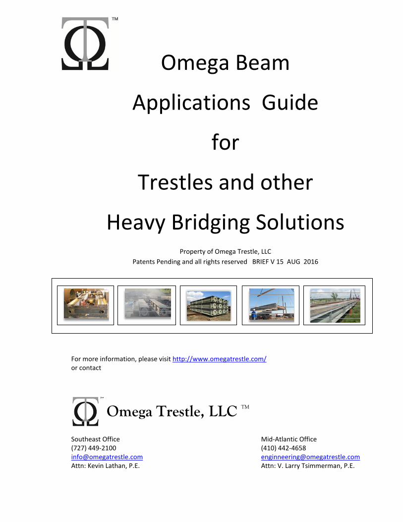
Omega Beam
Applications Guide
for
Trestles and other
Heavy Bridging Solutions Property of Omega Trestle, LLC
Patents Pending and all rights reserved BRIEF V 15 AUG 2016
For more information, please visit http://www.omegatrestle.com/ or contact
Southeast Office Mid‐Atlantic Office (727) 449‐2100 (410) 442‐4658 [email protected] [email protected] Attn: Kevin Lathan, P.E. Attn: V. Larry Tsimmerman, P.E.
Omega Trestle, LLC TM
2
OMEGA BEAM Application Guide Bridge Beam Brief V 15 Property of Omega Trestle, LLC Patents Pending All rights reserved www.OmegaTrestle.com for updated information
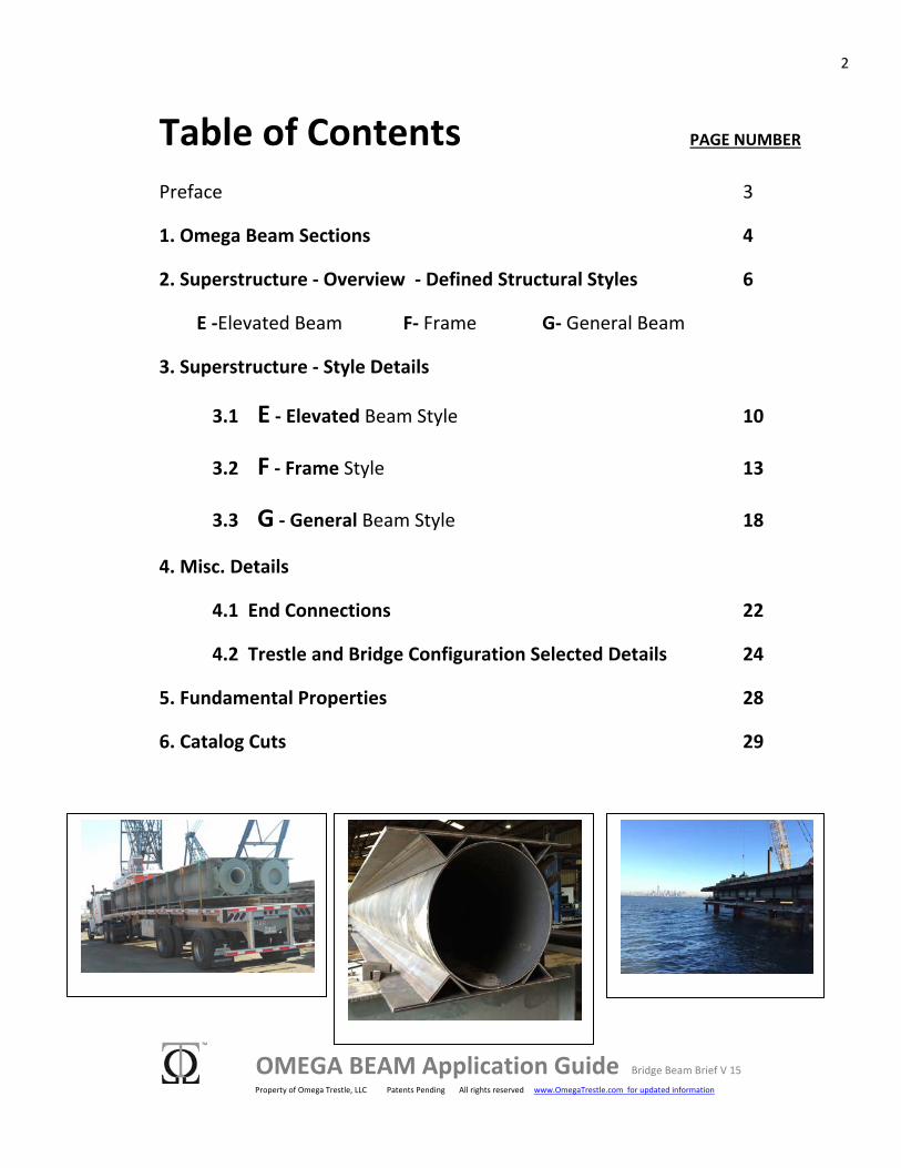
Table of Contents PAGE NUMBER Preface 3
1. Omega Beam Sections 4
2. Superstructure ‐ Overview ‐ Defined Structural Styles 6
E ‐Elevated Beam F‐ Frame G‐ General Beam
3. Superstructure ‐ Style Details
3.1 E ‐ Elevated Beam Style 10
3.2 F ‐ Frame Style 13
3.3 G ‐ General Beam Style 18
4. Misc. Details
4.1 End Connections 22
4.2 Trestle and Bridge Configuration Selected Details 24
5. Fundamental Properties 28
6. Catalog Cuts 29
3
OMEGA BEAM Application Guide Bridge Beam Brief V 15 Property of Omega Trestle, LLC Patents Pending All rights reserved www.OmegaTrestle.com for updated information
Preface GOAL:
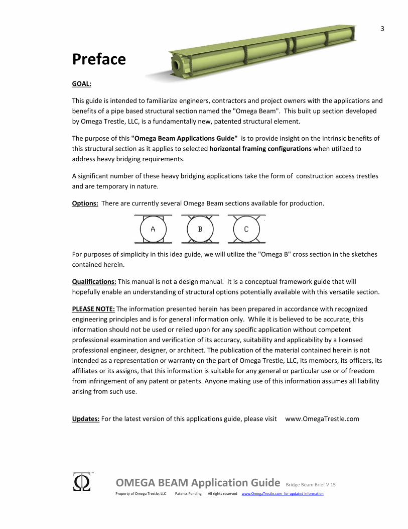
This guide is intended to familiarize engineers, contractors and project owners with the applications and benefits of a pipe based structural section named the "Omega Beam". This built up section developed by Omega Trestle, LLC, is a fundamentally new, patented structural element.
The purpose of this "Omega Beam Applications Guide" is to provide insight on the intrinsic benefits of this structural section as it applies to selected horizontal framing configurations when utilized to address heavy bridging requirements.
A significant number of these heavy bridging applications take the form of construction access trestles and are temporary in nature.
Options: There are currently several Omega Beam sections available for production.
For purposes of simplicity in this idea guide, we will utilize the "Omega B" cross section in the sketches contained herein.
Qualifications: This manual is not a design manual. It is a conceptual framework guide that will hopefully enable an understanding of structural options potentially available with this versatile section.
PLEASE NOTE: The information presented herein has been prepared in accordance with recognized engineering principles and is for general information only. While it is believed to be accurate, this information should not be used or relied upon for any specific application without competent professional examination and verification of its accuracy, suitability and applicability by a licensed professional engineer, designer, or architect. The publication of the material contained herein is not intended as a representation or warranty on the part of Omega Trestle, LLC, its members, its officers, its affiliates or its assigns, that this information is suitable for any general or particular use or of freedom from infringement of any patent or patents. Anyone making use of this information assumes all liability arising from such use.
Updates: For the latest version of this applications guide, please visit www.OmegaTrestle.com
4
OMEGA BEAM Application Guide Bridge Beam Brief V 15 Property of Omega Trestle, LLC Patents Pending All rights reserved www.OmegaTrestle.com for updated information
1. Omega Beam Sections
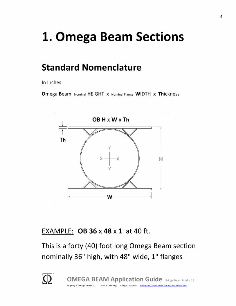
Standard Nomenclature In Inches
Omega Beam Nominal HEIGHT x Nominal Flange WIDTH x Thickness
EXAMPLE: OB 36 x 48 x 1 at 40 ft.
This is a forty (40) foot long Omega Beam section nominally 36" high, with 48" wide, 1" flanges
5
OMEGA BEAM Application Guide Bridge Beam Brief V 15 Property of Omega Trestle, LLC Patents Pending All rights reserved www.OmegaTrestle.com for updated information
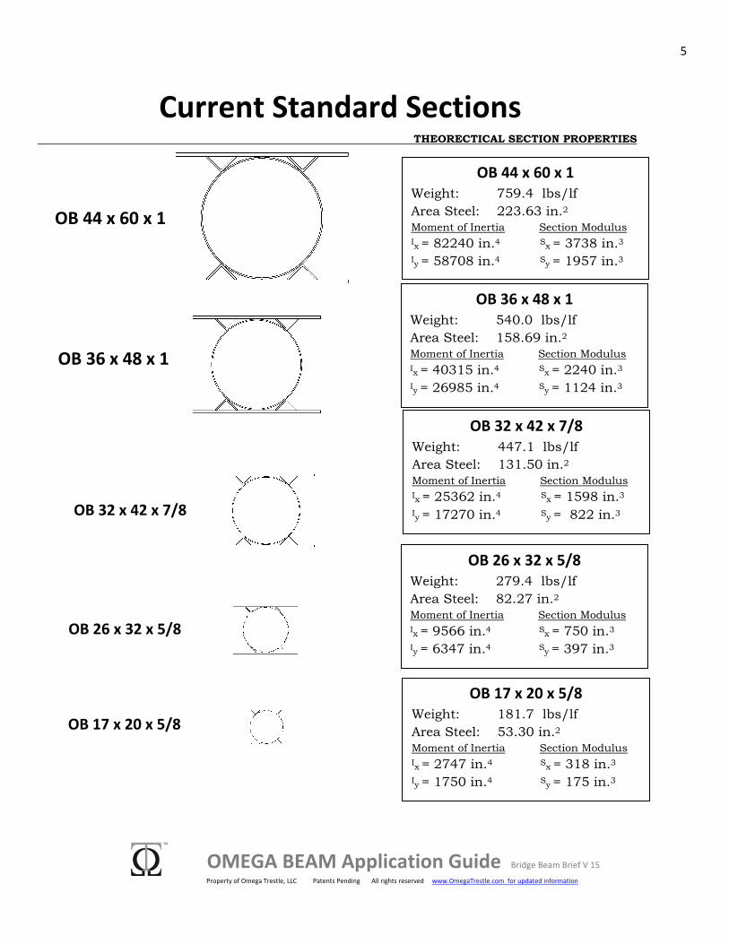
Current Standard Sections THEORECTICAL SECTION PROPERTIES
OB 44 x 60 x 1 Weight: 759.4 lbs/lf Area Steel: 223.63 in.2
Moment of Inertia Section Modulus Ix = 82240 in.4 Sx = 3738 in.3 Iy = 58708 in.4 Sy = 1957 in.3
OB 36 x 48 x 1 Weight: 540.0 lbs/lf Area Steel: 158.69 in.2
Moment of Inertia Section Modulus Ix = 40315 in.4 Sx = 2240 in.3 Iy = 26985 in.4 Sy = 1124 in.3
OB 32 x 42 x 7/8 Weight: 447.1 lbs/lf Area Steel: 131.50 in.2
Moment of Inertia Section Modulus Ix = 25362 in.4 Sx = 1598 in.3 Iy = 17270 in.4 Sy = 822 in.3
OB 26 x 32 x 5/8 Weight: 279.4 lbs/lf Area Steel: 82.27 in.2
Moment of Inertia Section Modulus Ix = 9566 in.4 Sx = 750 in.3 Iy = 6347 in.4 Sy = 397 in.3
OB 44 x 60 x 1
OB 36 x 48 x 1
OB 32 x 42 x 7/8
OB 26 x 32 x 5/8
OB 17 x 20 x 5/8 Weight: 181.7 lbs/lf Area Steel: 53.30 in.2
Moment of Inertia Section Modulus Ix = 2747 in.4 Sx = 318 in.3 Iy = 1750 in.4 Sy = 175 in.3
OB 17 x 20 x 5/8
6
OMEGA BEAM Application Guide Bridge Beam Brief V 15 Property of Omega Trestle, LLC Patents Pending All rights reserved www.OmegaTrestle.com for updated information
2. Superstructure Overview COMPARISONS TO ALTERNATIVE SECTIONS
As a horizontal load carrying member in trestle applications, the omega beam is structurally more efficient than beam sections built up from multiple W beams or plates. It also has superior weight to strength characteristics when compared to multiple W beams.
Unlike trestle beams built from plates or connected multiple beams, the omega beam section is naturally stable. As such, it can span longer distances and support heavier loads without additional bracing.
When omega beam trestle superstructure includes diaphragm members, the deck and substructure such as pier caps can be minimized, or even eliminated completely.
Omega sections are easily customizable to fit project requirements, and can be fabricated from standard plate, angle and pipe components as needed. This eliminates reliance on hot rolled beam schedules.
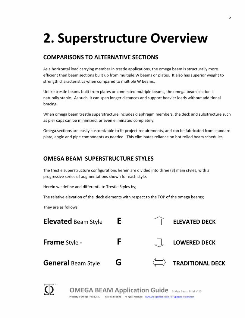
OMEGA BEAM SUPERSTRUCTURE STYLES
The trestle superstructure configurations herein are divided into three (3) main styles, with a progressive series of augmentations shown for each style.
Herein we define and differentiate Trestle Styles by;
The relative elevation of the deck elements with respect to the TOP of the omega beams;
They are as follows:
Elevated Beam Style E ELEVATED DECK
Frame Style ‐ F LOWERED DECK
General Beam Style G TRADITIONAL DECK
7
OMEGA BEAM Application Guide Bridge Beam Brief V 15 Property of Omega Trestle, LLC Patents Pending All rights reserved www.OmegaTrestle.com for updated information
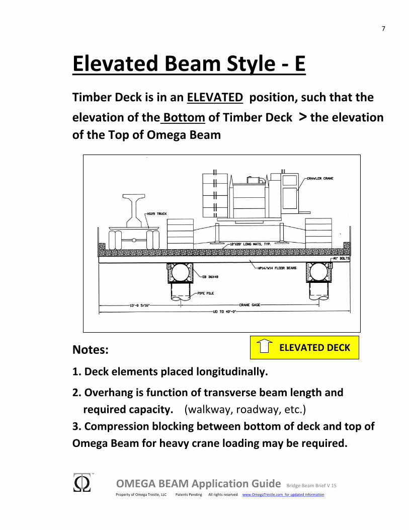
Elevated Beam Style ‐ E Timber Deck is in an ELEVATED position, such that the elevation of the Bottom of Timber Deck > the elevation of the Top of Omega Beam
Notes:
1. Deck elements placed longitudinally.
2. Overhang is function of transverse beam length and required capacity. (walkway, roadway, etc.) 3. Compression blocking between bottom of deck and top of Omega Beam for heavy crane loading may be required.
ELEVATED DECK
8
OMEGA BEAM Application Guide Bridge Beam Brief V 15 Property of Omega Trestle, LLC Patents Pending All rights reserved www.OmegaTrestle.com for updated information
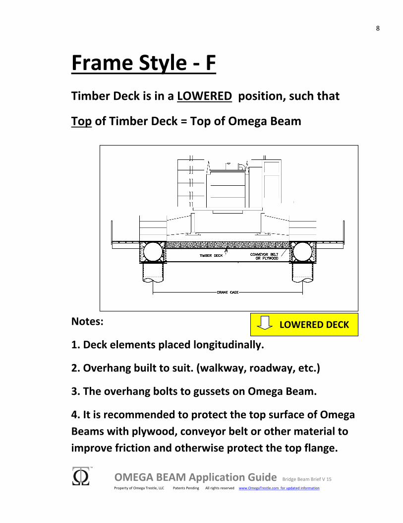
Frame Style ‐ F Timber Deck is in a LOWERED position, such that
Top of Timber Deck = Top of Omega Beam
Notes:
1. Deck elements placed longitudinally.
2. Overhang built to suit. (walkway, roadway, etc.)
3. The overhang bolts to gussets on Omega Beam.
4. It is recommended to protect the top surface of Omega Beams with plywood, conveyor belt or other material to improve friction and otherwise protect the top flange.
LOWERED DECK
9
OMEGA BEAM Application Guide Bridge Beam Brief V 15 Property of Omega Trestle, LLC Patents Pending All rights reserved www.OmegaTrestle.com for updated information
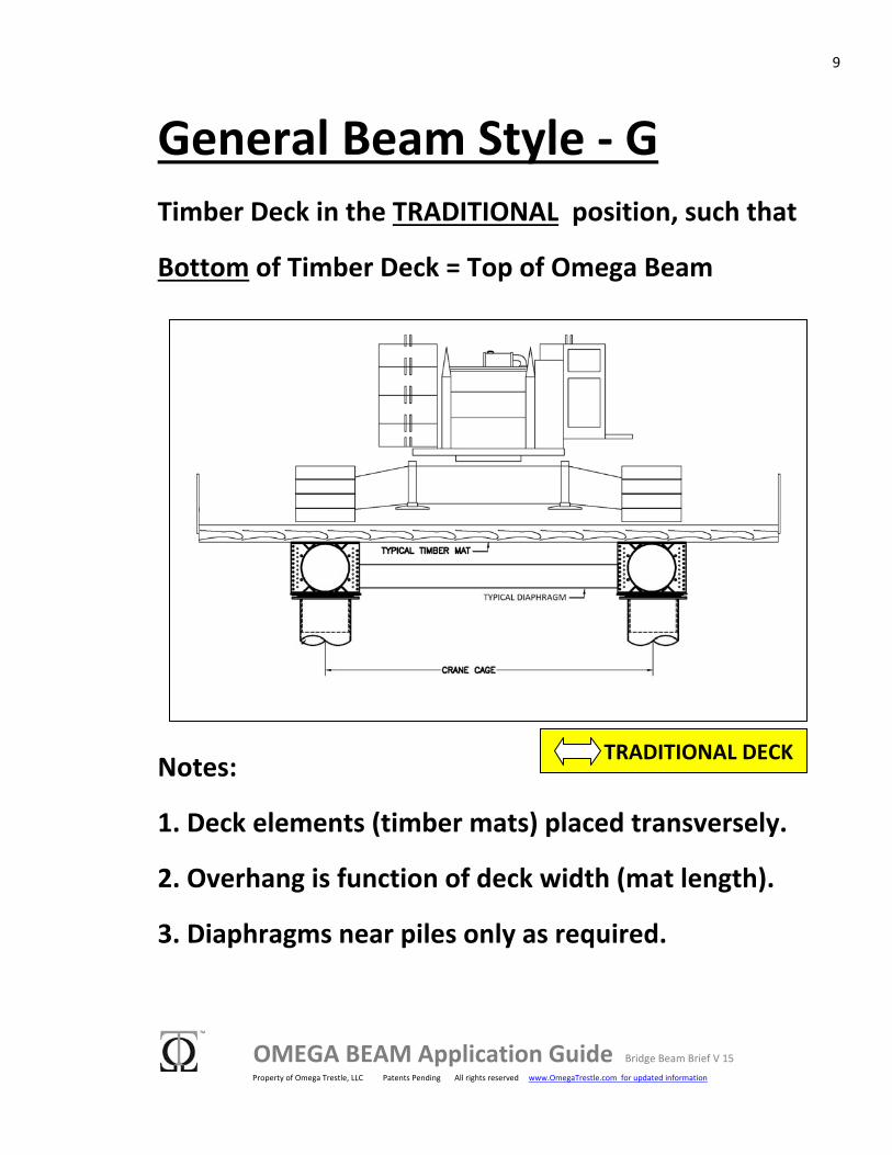
General Beam Style ‐ G Timber Deck in the TRADITIONAL position, such that
Bottom of Timber Deck = Top of Omega Beam
Notes:
1. Deck elements (timber mats) placed transversely.
2. Overhang is function of deck width (mat length).
3. Diaphragms near piles only as required.
TRADITIONAL DECK
10
OMEGA BEAM Application Guide Bridge Beam Brief V 15 Property of Omega Trestle, LLC Patents Pending All rights reserved www.OmegaTrestle.com for updated information
3. Superstructure Details 3.1 E ‐ Elevated Beam Style
What is unique?
The Omega Beams are used as the longitudinal structural component and "H" beams are positioned transversely to support the deck. This creates a readily scalable, heavy duty section from standard components.
High Capacity Distributed‐ The elevated style provides a load distribution pattern that enables the placement of heavy loads at any position on the deck. Deck can be blocked against the top of omega beams for additional capacity in that area.
Standard Components‐ 14" Steel H shaped beams and 20' timber crane mats for the deck section are readily available, and these elements are generally inventoried by heavy civil contactors.
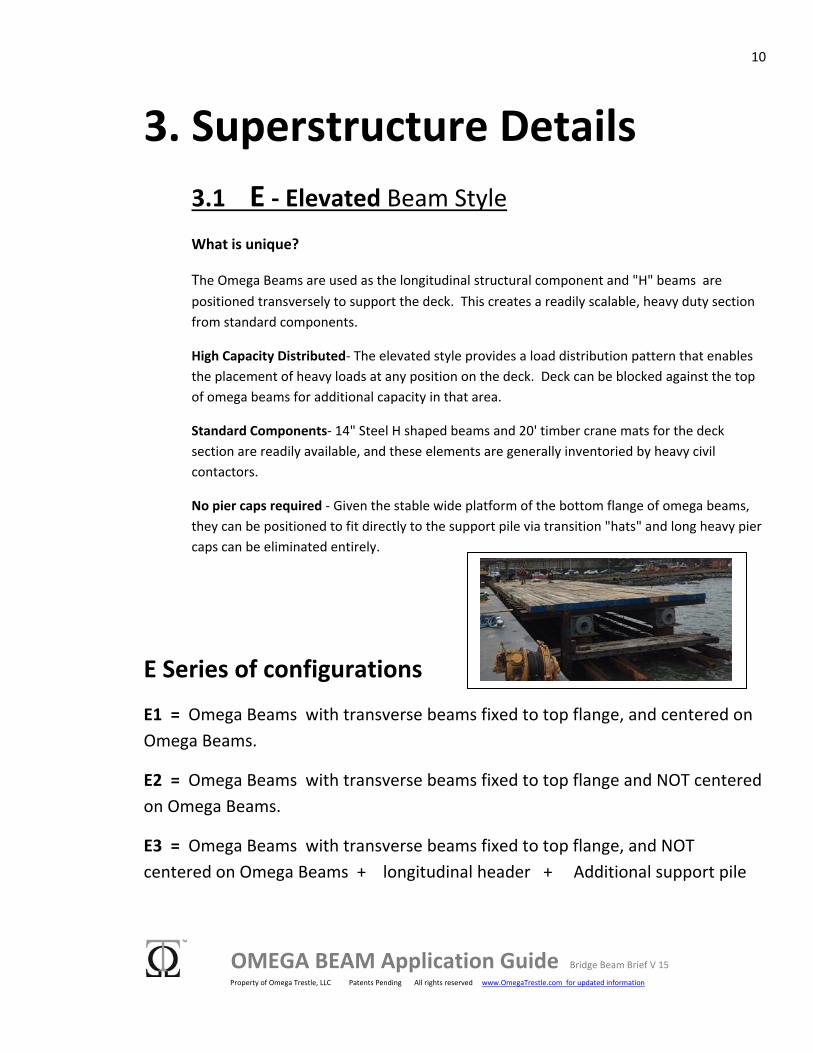
No pier caps required ‐ Given the stable wide platform of the bottom flange of omega beams, they can be positioned to fit directly to the support pile via transition "hats" and long heavy pier caps can be eliminated entirely.
E Series of configurations
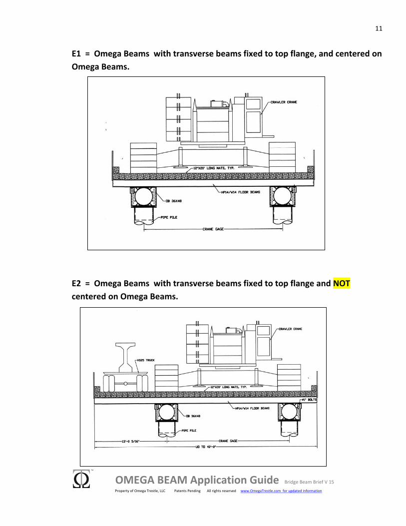
E1 = Omega Beams with transverse beams fixed to top flange, and centered on Omega Beams.
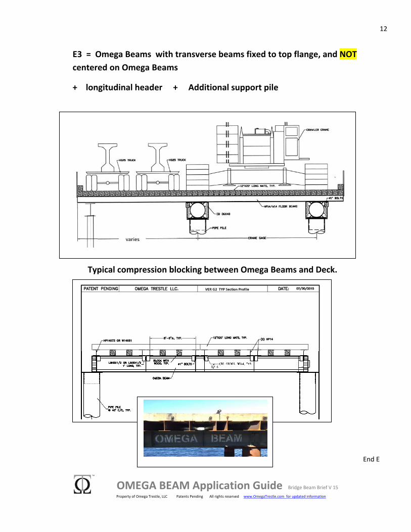
E2 = Omega Beams with transverse beams fixed to top flange and NOT centered on Omega Beams.
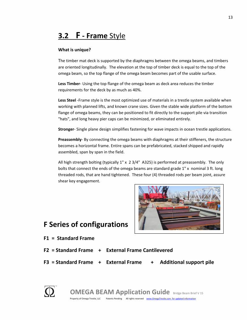
E3 = Omega Beams with transverse beams fixed to top flange, and NOT centered on Omega Beams + longitudinal header + Additional support pile
11
OMEGA BEAM Application Guide Bridge Beam Brief V 15 Property of Omega Trestle, LLC Patents Pending All rights reserved www.OmegaTrestle.com for updated information
E1 = Omega Beams with transverse beams fixed to top flange, and centered on Omega Beams.
E2 = Omega Beams with transverse beams fixed to top flange and NOT centered on Omega Beams.
12
OMEGA BEAM Application Guide Bridge Beam Brief V 15 Property of Omega Trestle, LLC Patents Pending All rights reserved www.OmegaTrestle.com for updated information
E3 = Omega Beams with transverse beams fixed to top flange, and NOT centered on Omega Beams
+ longitudinal header + Additional support pile
Typical compression blocking between Omega Beams and Deck.
End E
13
OMEGA BEAM Application Guide Bridge Beam Brief V 15 Property of Omega Trestle, LLC Patents Pending All rights reserved www.OmegaTrestle.com for updated information
3.2 F ‐ Frame Style
What is unique?
The timber mat deck is supported by the diaphragms between the omega beams, and timbers are oriented longitudinally. The elevation at the top of timber deck is equal to the top of the omega beam, so the top flange of the omega beam becomes part of the usable surface.
Less Timber‐ Using the top flange of the omega beam as deck area reduces the timber requirements for the deck by as much as 40%.
Less Steel ‐Frame style is the most optimized use of materials in a trestle system available when working with planned lifts, and known crane sizes. Given the stable wide platform of the bottom flange of omega beams, they can be positioned to fit directly to the support pile via transition "hats", and long heavy pier caps can be minimized, or eliminated entirely.
Stronger‐ Single plane design simplifies fastening for wave impacts in ocean trestle applications.
Preassembly‐ By connecting the omega beams with diaphragms at their stiffeners, the structure becomes a horizontal frame. Entire spans can be prefabricated, stacked shipped and rapidly assembled, span by span in the field.
All high strength bolting (typically 1" x 2 3/4" A325) is performed at preassembly. The only bolts that connect the ends of the omega beams are standard grade 1" x nominal 3 ft. long threaded rods, that are hand tightened. These four (4) threaded rods per beam joint, assure shear key engagement.
F Series of configurations
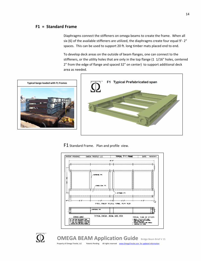
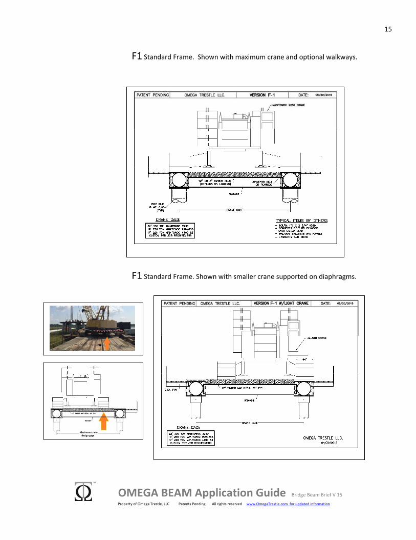
F1 = Standard Frame
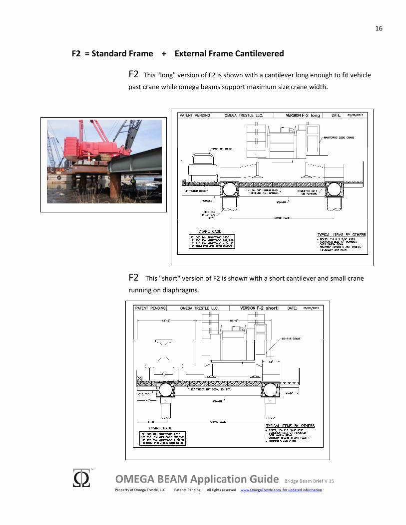
F2 = Standard Frame + External Frame Cantilevered
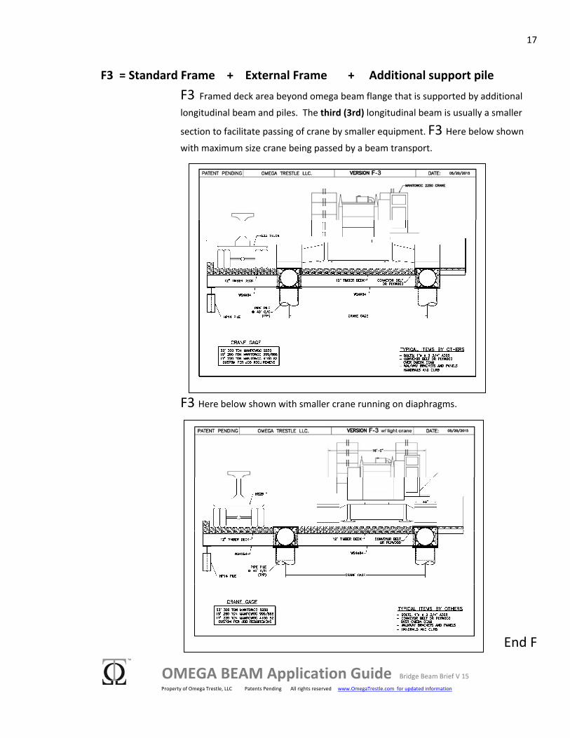
F3 = Standard Frame + External Frame + Additional support pile
14
OMEGA BEAM Application Guide Bridge Beam Brief V 15 Property of Omega Trestle, LLC Patents Pending All rights reserved www.OmegaTrestle.com for updated information
F1 = Standard Frame
Diaphragms connect the stiffeners on omega beams to create the frame. When all six (6) of the available stiffeners are utilized, the diaphragms create four equal 9'‐ 2" spaces. This can be used to support 20 ft. long timber mats placed end to end.
To develop deck areas on the outside of beam flanges, one can connect to the stiffeners, or the utility holes that are only in the top flange (1 1/16" holes, centered 2" from the edge of flange and spaced 32" on center) to support additional deck area as needed.
F1 Standard Frame. Plan and profile view.
Typical barge loaded with F1 Frames
15
OMEGA BEAM Application Guide Bridge Beam Brief V 15 Property of Omega Trestle, LLC Patents Pending All rights reserved www.OmegaTrestle.com for updated information
F1 Standard Frame. Shown with maximum crane and optional walkways.
F1 Standard Frame. Shown with smaller crane supported on diaphragms.
16
OMEGA BEAM Application Guide Bridge Beam Brief V 15 Property of Omega Trestle, LLC Patents Pending All rights reserved www.OmegaTrestle.com for updated information
F2 = Standard Frame + External Frame Cantilevered
F2 This "long" version of F2 is shown with a cantilever long enough to fit vehicle past crane while omega beams support maximum size crane width.
F2 This "short" version of F2 is shown with a short cantilever and small crane
running on diaphragms.
17
OMEGA BEAM Application Guide Bridge Beam Brief V 15 Property of Omega Trestle, LLC Patents Pending All rights reserved www.OmegaTrestle.com for updated information
F3 = Standard Frame + External Frame + Additional support pile F3 Framed deck area beyond omega beam flange that is supported by additional
longitudinal beam and piles. The third (3rd) longitudinal beam is usually a smaller
section to facilitate passing of crane by smaller equipment. F3 Here below shown with maximum size crane being passed by a beam transport.
F3 Here below shown with smaller crane running on diaphragms.
End F
18
OMEGA BEAM Application Guide Bridge Beam Brief V 15 Property of Omega Trestle, LLC Patents Pending All rights reserved www.OmegaTrestle.com for updated information
3.3 G ‐ General Beam Style
What is unique?
The General Beam Style is the most simplistic form of trestle superstructure. This style is typified by the use of top flange of the omega beams to carry the transverse deck elements.
Simple‐ This is simple and fast to assemble, but does require much longer timber deck mat components that are not always readily available.
Diaphragms vs. Pier Caps‐ For secondary load support (loaders, smaller cranes, heavy trucks, etc.) transverse diaphragms can often be substituted for pier caps. These less frequent diaphragms would support longitudinal members intended to augment the timber deck span between omega beams. Omega beams torsion capacity makes this option possible.
General Beam Style ‐ G Series of configurations
G0 = Rapid Access Deployment with no deck, just set beams & GO !
G1 = Traditionally positioned mats transverse to omega beams ‐
G1 configuration is also known as the " EASY BRIDGE "
G1 Truck = G1 + SINGLE additional longitudinal beam under mat deck
G1 HEAVY = G1 + MANY additional longitudinal beams under mat deck
19
OMEGA BEAM Application Guide Bridge Beam Brief V 15 Property of Omega Trestle, LLC Patents Pending All rights reserved www.OmegaTrestle.com for updated information
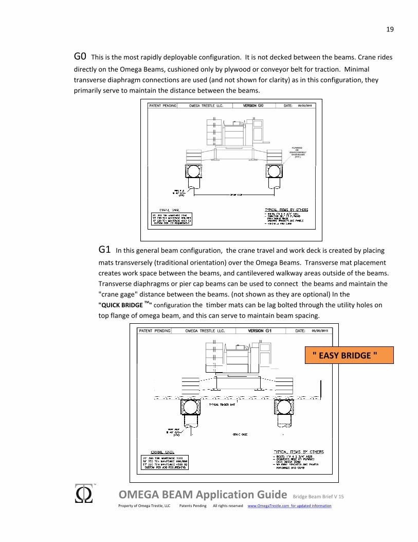
G0 This is the most rapidly deployable configuration. It is not decked between the beams. Crane rides
directly on the Omega Beams, cushioned only by plywood or conveyor belt for traction. Minimal transverse diaphragm connections are used (and not shown for clarity) as in this configuration, they primarily serve to maintain the distance between the beams.
G1 In this general beam configuration, the crane travel and work deck is created by placing
mats transversely (traditional orientation) over the Omega Beams. Transverse mat placement creates work space between the beams, and cantilevered walkway areas outside of the beams. Transverse diaphragms or pier cap beams can be used to connect the beams and maintain the "crane gage" distance between the beams. (not shown as they are optional) In the "QUICK BRIDGE TM" configuration the timber mats can be lag bolted through the utility holes on top flange of omega beam, and this can serve to maintain beam spacing.
" EASY BRIDGE "
20
OMEGA BEAM Application Guide Bridge Beam Brief V 15 Property of Omega Trestle, LLC Patents Pending All rights reserved www.OmegaTrestle.com for updated information
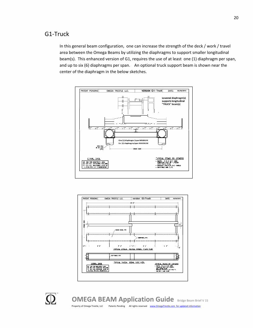
G1‐Truck
In this general beam configuration, one can increase the strength of the deck / work / travel area between the Omega Beams by utilizing the diaphragms to support smaller longitudinal beam(s). This enhanced version of G1, requires the use of at least one (1) diaphragm per span, and up to six (6) diaphragms per span. An optional truck support beam is shown near the center of the diaphragm in the below sketches.
21
OMEGA BEAM Application Guide Bridge Beam Brief V 15 Property of Omega Trestle, LLC Patents Pending All rights reserved www.OmegaTrestle.com for updated information
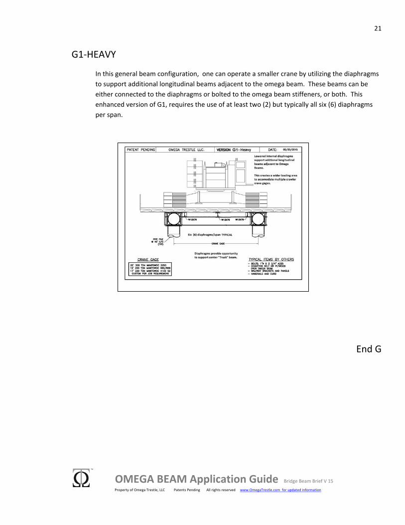
G1‐HEAVY
In this general beam configuration, one can operate a smaller crane by utilizing the diaphragms to support additional longitudinal beams adjacent to the omega beam. These beams can be either connected to the diaphragms or bolted to the omega beam stiffeners, or both. This enhanced version of G1, requires the use of at least two (2) but typically all six (6) diaphragms per span.
End G
22
OMEGA BEAM Application Guide Bridge Beam Brief V 15 Property of Omega Trestle, LLC Patents Pending All rights reserved www.OmegaTrestle.com for updated information
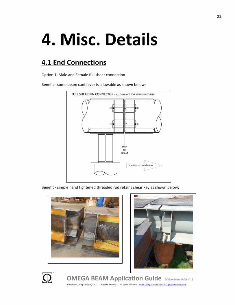
4. Misc. Details 4.1 End Connections Option 1. Male and Female full shear connection
Benefit ‐ some beam cantilever is allowable as shown below;
Benefit ‐ simple hand tightened threaded rod retains shear key as shown below;
23
OMEGA BEAM Application Guide Bridge Beam Brief V 15 Property of Omega Trestle, LLC Patents Pending All rights reserved www.OmegaTrestle.com for updated information
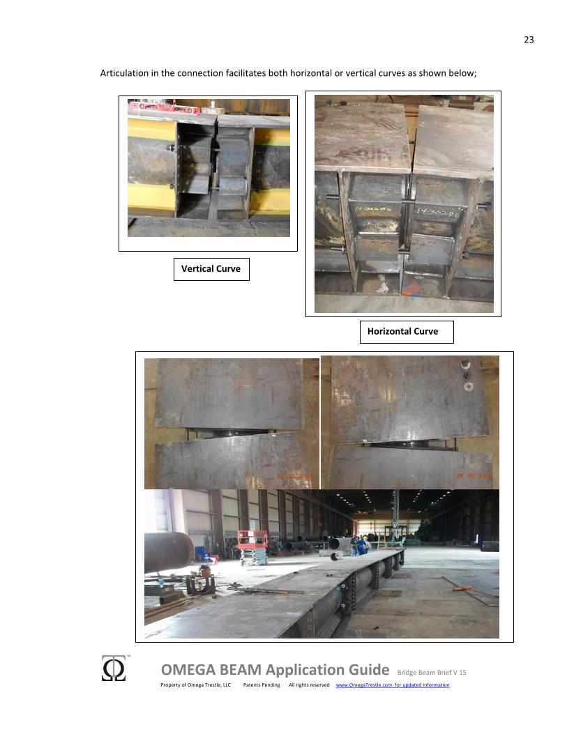
Articulation in the connection facilitates both horizontal or vertical curves as shown below;
Horizontal Curve
Vertical Curve

24
OMEGA BEAM Application Guide Bridge Beam Brief V 15 Property of Omega Trestle, LLC Patents Pending All rights reserved www.OmegaTrestle.com for updated information
Option 2. Simple bolted end plate connection shown here below
4.2 Trestle and Bridge Configuration Details The Omega Beam is a versatile, scalable, wide platform, torsion resistant structural element. Herein are some additional concepts and details that relate to Trestles and Bridges that may lead to further conceptual development.
TYPICAL LONGITUDINAL MAT PLACEMENT ‐ Shown here as partially placed on two (2) VER F‐2 spans.
25
OMEGA BEAM Application Guide Bridge Beam Brief V 15 Property of Omega Trestle, LLC Patents Pending All rights reserved www.OmegaTrestle.com for updated information
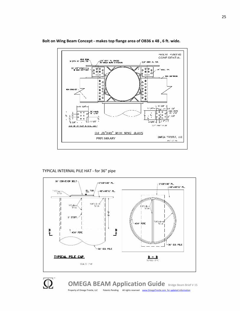
Bolt on Wing Beam Concept ‐ makes top flange area of OB36 x 48 , 6 ft. wide.
TYPICAL INTERNAL PILE HAT ‐ for 36" pipe
26
OMEGA BEAM Application Guide Bridge Beam Brief V 15 Property of Omega Trestle, LLC Patents Pending All rights reserved www.OmegaTrestle.com for updated information
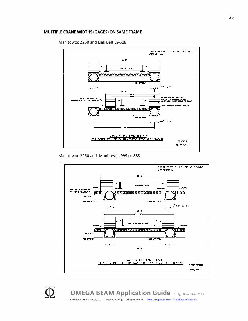
MULTIPLE CRANE WIDTHS (GAGES) ON SAME FRAME
Manitowoc 2250 and Link Belt LS‐518
Manitowoc 2250 and Manitowoc 999 or 888
27
OMEGA BEAM Application Guide Bridge Beam Brief V 15 Property of Omega Trestle, LLC Patents Pending All rights reserved www.OmegaTrestle.com for updated information
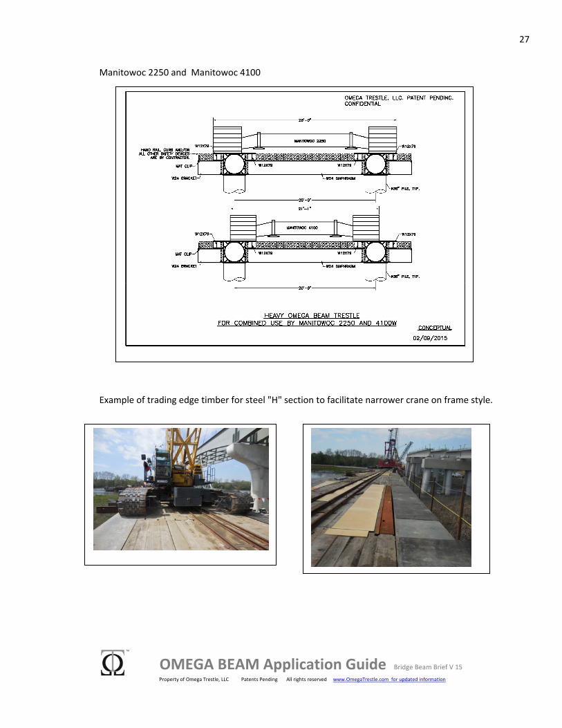
Manitowoc 2250 and Manitowoc 4100
Example of trading edge timber for steel "H" section to facilitate narrower crane on frame style.
28
OMEGA BEAM Application Guide Bridge Beam Brief V 15 Property of Omega Trestle, LLC Patents Pending All rights reserved www.OmegaTrestle.com for updated information
5. Fundamental Properties Fundamental New Shape Benefits:
SCALEABLE: The Omega Beam is scalable to suit any application. Logistics and your imagination are the only constraints.
UNBRACED LENGTH: In all sizes, it provides a torsion resistant structural element that is capable of much longer un‐braced lengths than traditional W or HP beam sections of similar height. The omega beam section has a minor axis strength that is approximately half of its major axis strength.
WIDE PLATFORM: There are unique solutions to structural problems that can be solved more efficiently with wide platform elements. Many of these utilize the wide flanges for logistical advantage like you can see in this guide, where we place heavy movable loads directly on the Omega Beams. Other applications that are in the process of development include: utility bridges, rapidly assembled roadway structures, railroad trestles, RO‐RO vessel ramps, and pedestrian bridges.
FRAMING: As a single wide platform torsion element, Omega Beams can be incorporated into structural frames in ways that are not possible or practical with multiple beam or truss elements. Many space frame opportunities have yet to be explored.
CORROSION RESISTANCE: Continuous pipe core with sealed ends creates a section that has a significantly reduced area exposed to corrosive elements.
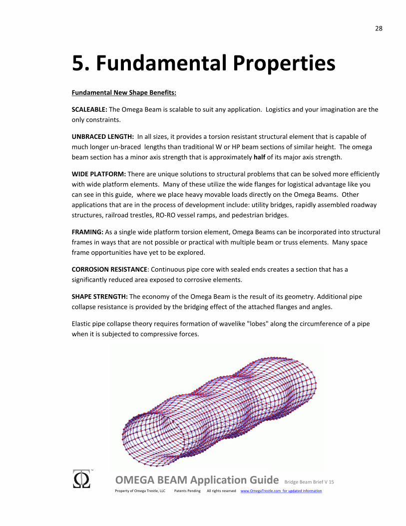
SHAPE STRENGTH: The economy of the Omega Beam is the result of its geometry. Additional pipe collapse resistance is provided by the bridging effect of the attached flanges and angles.
Elastic pipe collapse theory requires formation of wavelike "lobes" along the circumference of a pipe when it is subjected to compressive forces.
29
OMEGA BEAM Application Guide Bridge Beam Brief V 15 Property of Omega Trestle, LLC Patents Pending All rights reserved www.OmegaTrestle.com for updated information
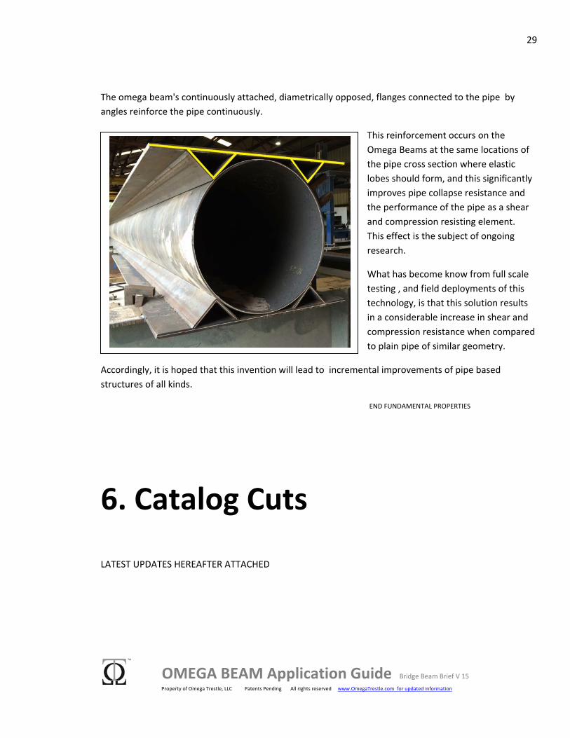
The omega beam's continuously attached, diametrically opposed, flanges connected to the pipe by angles reinforce the pipe continuously.
This reinforcement occurs on the Omega Beams at the same locations of the pipe cross section where elastic lobes should form, and this significantly improves pipe collapse resistance and the performance of the pipe as a shear and compression resisting element. This effect is the subject of ongoing research.
What has become know from full scale testing , and field deployments of this technology, is that this solution results in a considerable increase in shear and compression resistance when compared to plain pipe of similar geometry.
Accordingly, it is hoped that this invention will lead to incremental improvements of pipe based structures of all kinds.
END FUNDAMENTAL PROPERTIES
6. Catalog Cuts
LATEST UPDATES HEREAFTER ATTACHED