Embed Size (px)
Citation preview
ROADS AND MARITIME SERVICES (RMS)
RMS SPECIFICATION D&C TS918
OMCS REQUIREMENTS - ROAD TUNNEL AND UNDERPASS LIGHTING
NOTICE
This document is a Roads and Maritime Services D&C Specification. It has been developed for use with Design & Construct roadworks and bridgeworks contracts let by Roads and Maritime Services. It is not suitable for any other purpose and must not be used for any other purpose or in any other context.
Copyright in this document belongs to Roads and Maritime Services.
REVISION REGISTER
Ed/Rev Number
Clause Number Description of Revision Authorised
By Date
Ed 1/Rev 0 First issue. DCS 21.08.17
Edition 1 / Revision 0 ROADS AND MARITIME SERVICES August 2017

SPECIFICATION D&C TS918
OMCS REQUIREMENTS - ROAD TUNNEL AND UNDERPASS LIGHTING
Copyright – Roads and Maritime Services IC-DC-TS918
VERSION FOR: DATE:
Edition 1 / Revision 0 ROADS AND MARITIME SERVICES August 2017

OMCS Requirements - Road Tunnel and Underpass Lighting D&C TS918
CONTENTS
CLAUSE PAGE
FOREWORD ............................................................................................................................................... II RMS Copyright and Use of this Document ................................................................................... ii Base Specification ......................................................................................................................... ii
1 GENERAL ........................................................................................................................................ 1 1.1 Scope .............................................................................................................................. 1 1.2 Related Specifications .................................................................................................... 1 1.3 Structure of the Specification ......................................................................................... 2 1.4 Definitions and Acronyms .............................................................................................. 3
2 DESIGN ........................................................................................................................................... 4 2.1 General ........................................................................................................................... 4 2.2 Tunnel Lighting .............................................................................................................. 4 2.3 Underpass Lighting ........................................................................................................ 5 2.4 Mains Failure Lighting ................................................................................................... 5 2.5 Emergency Lighting/Signage in Tunnel ......................................................................... 6 2.6 Lighting for Services Galleries and Emergency Egress Passages .................................. 6 2.7 Illuminated Tunnel Signs ............................................................................................... 6 2.8 Lighting Photometer Control System for Tunnel ........................................................... 6 2.9 Design Compliance ........................................................................................................ 7 2.10 Alternative Design and Technology ............................................................................... 8
3 EQUIPMENT AND COMPONENTS ..................................................................................................... 8 3.1 General ........................................................................................................................... 8 3.2 Luminaires ...................................................................................................................... 9 3.3 Control Gear ................................................................................................................. 10 3.4 Illuminated Tunnel Signs ............................................................................................. 10 3.5 Photometers .................................................................................................................. 10 3.6 Equipment List ............................................................................................................. 11 3.7 Certificate of Suitability ............................................................................................... 11
4 INSTALLATION .............................................................................................................................. 11 4.1 General ......................................................................................................................... 11 4.2 Cableway Identification ............................................................................................... 11 4.3 Cable Identification ...................................................................................................... 12 4.4 Luminaires .................................................................................................................... 12
5 INSPECTION AND TESTING ............................................................................................................ 13 5.1 General ......................................................................................................................... 13 5.2 Inspection by RMS Representative .............................................................................. 13 5.3 Production Tests ........................................................................................................... 13 5.4 Witness Point and Hold Point ...................................................................................... 14
6 COMMISSIONING .......................................................................................................................... 14 6.1 General ......................................................................................................................... 14 6.2 Verification of Lighting Performance .......................................................................... 15 6.3 Commissioning Report ................................................................................................. 15 6.4 Inspection by RMS Representative .............................................................................. 15 6.5 Testing with the OMCS ................................................................................................ 15 6.6 Witness Point and Hold Point ...................................................................................... 16
Ed 1 / Rev 0 i
D&C TS918 OMCS Requirements - Road Tunnel and Underpass Lighting
7 SPARE PARTS ................................................................................................................................ 16
ANNEXURES TS918/A AND TS918/B – (NOT USED) .............................................................................. 17
ANNEXURE TS918/C – SCHEDULES OF HOLD POINTS AND IDENTIFIED RECORDS ................................ 17 C1 Schedule of Hold Points ............................................................................................... 17 C2 Schedule of Identified Records..................................................................................... 17
ANNEXURE TS918/D – PLANNING DOCUMENTS .................................................................................... 18
ANNEXURES TS918/E TO TS918/L – (NOT USED) ................................................................................. 18
ANNEXURE TS918/M – REFERENCED DOCUMENTS .............................................................................. 19
LAST PAGE OF THIS DOCUMENT IS .......................................................................................................... 20
FOREWORD
RMS COPYRIGHT AND USE OF THIS DOCUMENT
Copyright in this document belongs to Roads and Maritime Services.
When this document forms part of a deed
This document should be read with all the documents forming the Project Deed.
When this document does not form part of a deed
This copy is not a controlled document. Observe the Notice that appears on the first page of the copy controlled by RMS. A full copy of the latest version of the document is available on the RMS Internet website: http://www.rms.nsw.gov.au/business-industry/partners-suppliers/specifications/index.html
BASE SPECIFICATION
This document is based on Specification RMS R158 Edition 1 Revision 3.
ii Ed 1 / Rev 0
(RMS COPYRIGHT AND USE OF THIS DOCUMENT - Refer to the Foreword after the Table of Contents)
RMS SPECIFICATION D&C TS918
OMCS REQUIREMENTS - ROAD TUNNEL AND UNDERPASS LIGHTING
1 GENERAL
1.1 SCOPE
This Specification sets out the requirements of the design, supply, installation and commissioning of road tunnel and underpass lighting (RTUL), to provide conditions in the tunnel or underpass that are safe for the full range of operational requirements, including during emergencies.
This Specification does not cover the requirements of approach road lighting.
1.2 RELATED SPECIFICATIONS
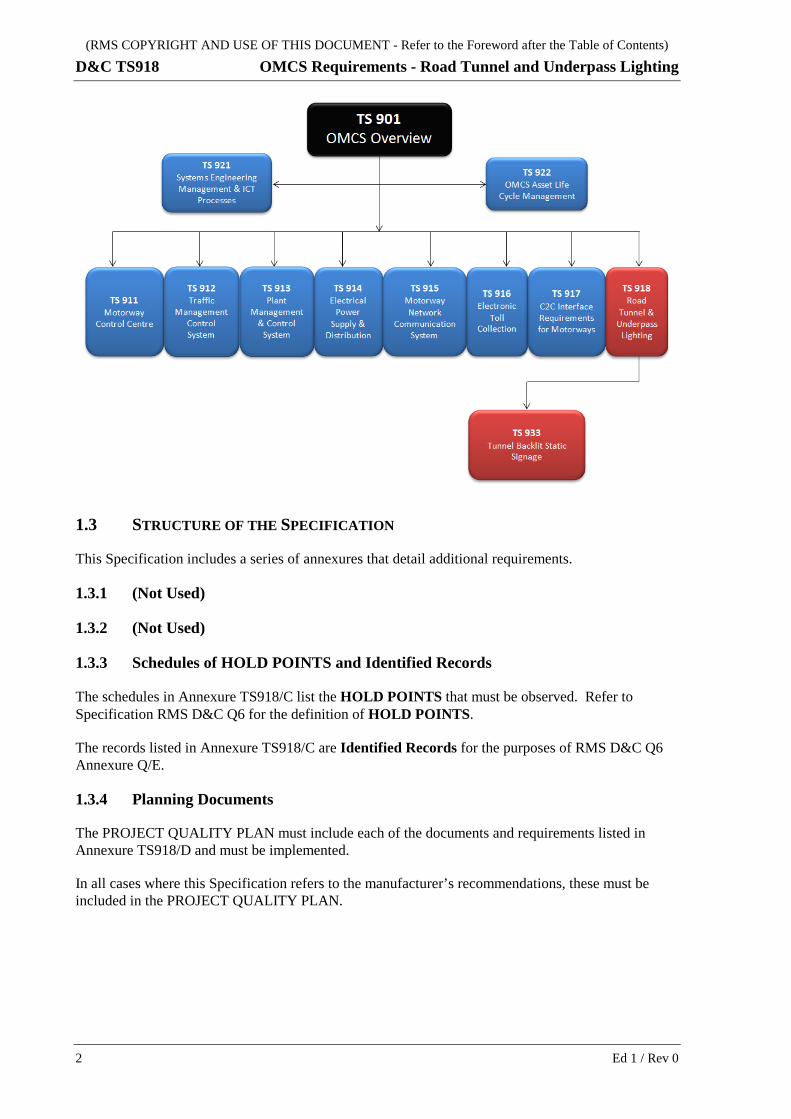
This Specification is a Level 2 document which forms part of the suite of RMS specification documents for the Operations Management and Control System (OMCS) for Motorways (see figure below). Other documents within the suite are:
Level 1
• D&C TS901 “OMCS Overview and General Requirements”;
Level 2
• D&C TS911 “OMCS Requirements - Motorway Control Centre”;
• D&C TS912 “OMCS Requirements - Traffic Management and Control System”;
• D&C TS913 “OMCS Requirements - Plant Management and Control System”;
• D&C TS914 “OMCS Requirements - Electrical Power Supply and Distribution System”;
• D&C TS915 “OMCS Requirements - Motorway Network Communications System”;
• D&C TS916 “OMCS Requirements - Electronic Toll Collection System”;
• D&C TS917 “OMCS Requirements - C2C Interface for Motorways”;
Level 3
• D&C TS931 “Tunnel and Underpass Main Switchboard, Distribution Boards and Control Panels”;
• D&C TS933 “Tunnel Backlit Static Signage”.
Ed 1 / Rev 0 1
(RMS COPYRIGHT AND USE OF THIS DOCUMENT - Refer to the Foreword after the Table of Contents)
D&C TS918 OMCS Requirements - Road Tunnel and Underpass Lighting
1.3 STRUCTURE OF THE SPECIFICATION
This Specification includes a series of annexures that detail additional requirements.
1.3.1 (Not Used)
1.3.2 (Not Used)
1.3.3 Schedules of HOLD POINTS and Identified Records
The schedules in Annexure TS918/C list the HOLD POINTS that must be observed. Refer to Specification RMS D&C Q6 for the definition of HOLD POINTS.
The records listed in Annexure TS918/C are Identified Records for the purposes of RMS D&C Q6 Annexure Q/E.
1.3.4 Planning Documents
The PROJECT QUALITY PLAN must include each of the documents and requirements listed in Annexure TS918/D and must be implemented.
In all cases where this Specification refers to the manufacturer’s recommendations, these must be included in the PROJECT QUALITY PLAN.
2 Ed 1 / Rev 0
(RMS COPYRIGHT AND USE OF THIS DOCUMENT - Refer to the Foreword after the Table of Contents)
OMCS Requirements - Road Tunnel and Underpass Lighting D&C TS918
1.3.5 (Not Used)
1.3.6 Referenced Documents
Standards, specifications and test methods are referred to in abbreviated form (e.g. AS 2350). For convenience, the full titles are given in Annexure TS918/M.
1.4 DEFINITIONS AND ACRONYMS
1.4.1 Definitions
The terms “you” and “your” mean “the Contractor” and “the Contractor’s” respectively.
In addition to the definitions given in AS/NZS 60598.1, the following definitions also apply to this Specification:
Cableway System of conduits, including their fittings, pits and equipment housing, but excluding the communication and electrical cables and equipment.
Continuous lighting Near-continuous line lighting system as defined in CIE 88 “Guide for the Lighting of Road Tunnels and Underpasses”. In such a system, the distance between the end of one luminaire and the beginning of the next luminaire must be less than the total length of the luminaire.
Electricity Supply Authority
The Electricity Distributor within whose distribution area the electrical installation is situated or where the installation work is carried out.
Lamp Replaceable light producing element of the luminaire. A luminaire may comprise one or more lamps.
Luminaire An apparatus, which distributes light transmitted from one or more lamps. It comprises the complete assembly including lamps, housing and all the parts necessary for supporting, fixing and protecting the lamps and where necessary, circuit auxiliaries together with the means for connecting them to the electrical power supply.
Working width The minimum width required to prevent an impacting design vehicle from colliding with an object situated behind a road safety barrier system. This comprises the dynamic deflection of the road safety barrier (if any) and an extra width to allow for the roll (i.e. vertical rotation) of the impacting vehicle.
1.4.2 Acronyms
The following acronyms apply to this Specification:
HPS High pressure sodium
LED Light-emitting diode
LEP Longitudinal egress passage
OMCS Operations Management and Control System
RTUL Road tunnel and underpass lighting
SIT System Integration Testing
Ed 1 / Rev 0 3
(RMS COPYRIGHT AND USE OF THIS DOCUMENT - Refer to the Foreword after the Table of Contents)
D&C TS918 OMCS Requirements - Road Tunnel and Underpass Lighting
SWTC Project Deed Scope of Work and Technical Criteria
UAT User Acceptance Testing
UPS Uninterruptible power supply
2 DESIGN
2.1 GENERAL
2.1.1 Compatibility
The RTUL must be compatible with the OMCS computer systems, equipment and communication networks used for the Motorway.
2.1.2 Reliability
The RTUL must be reliable, designed to be fault tolerant and fail-safe with layers of redundancy, so that any singular failure of the RTUL components will not adversely impact the operation of the RTUL and overall OMCS.
2.1.3 Location Within Carriageway
Switchboards, control panels, luminaires, conduits and cables must not be located within the trafficable section or the working width (refer Clause 1.4.1 for definition of “working width”) of the tunnel carriageway.
2.2 TUNNEL LIGHTING
2.2.1 General
(a) Tunnel lighting design must be in accordance with AS/NZS 1158.5, using the operating speeds stated in the SWTC.
(b) Provide calculations for the lighting design demonstrating compliance with the above.
(c) Counterbeam or pro-beam lighting systems must not be used in any part of the tunnels.
(d) Where tunnels or ramps have a carriageway width greater than 5.5 m, the luminaires must be located such that it is possible to carry out maintenance work on the luminaires without closing the whole carriageway.
(e) Power supply for the tunnel lighting must be in accordance with RMS D&C TS914.
2.2.2 Automatic Lighting Control
(a) The lighting/luminance level must be automatically and gradually decreased/increased to the required level as calculated in accordance with AS/NZS 1158.5, for the specific zones in the tunnel.
4 Ed 1 / Rev 0
(RMS COPYRIGHT AND USE OF THIS DOCUMENT - Refer to the Foreword after the Table of Contents)
OMCS Requirements - Road Tunnel and Underpass Lighting D&C TS918
(b) If a stepped lighting control system is used, a minimum of 6 stages of lighting/luminance levels must be provided, with the lowest being for night-time conditions and the highest for bright sunshine conditions.
(c) The stages of lighting set in the various zones must be automatically controlled and adjusted as the outside conditions vary. Photometers located at the stopping sight distance act as sensors and send signals to the automatic control system to set and change the luminance levels within the tunnel (refer Clause 2.8).
2.2.3 Design Type
(a) The lighting system must be of a “continuous lighting” type design (refer Clause 1.4.1 for definition of “continuous lighting”), using luminaires of any type that comply with the luminance values in AS/NZS 1158.5 and the SWTC.
(b) This must be supplemented by luminaires to provide boost lighting in the threshold and transition zones, in accordance with AS/NZS 1158.5. Depending on the final design, luminaires providing boost lighting may be required in other zones.
(c) The visual impact at tunnel portals of cable trays supporting luminaires and cables must be addressed in the urban design. Luminaires and their supports must not be located within one metre inside of the tunnel portals.
2.2.4 Electromagnetic Interference
(a) The system must comply with AS/NZS 61347.2.8 for limitation of harmonic feedback and AS/NZS CISPR 14.1 to ensure that electromagnetic radiation will not affect any radio re-broadcast system which will be installed.
2.3 UNDERPASS LIGHTING
The design requirements of underpass lighting are same as those for tunnel lighting, clarified as follows:
(a) Underpass lighting design must be in accordance with AS/NZS 1158.5, as for tunnel lighting.
(b) Power supply for the underpass lighting must be in accordance with RMS D&C TS914, as for tunnel lighting.
(c) The stages of lighting in the various zones must be automatically controlled and adjusted as the outside conditions vary as for tunnel lighting, but if a stepped lighting control system is used, a minimum of 4 stages of lighting/luminance levels must be provided, with the lowest being for night-time conditions and the highest for bright sunshine conditions.
(d) Where underpasses have a carriageway width greater than 5.5 m, the luminaires must be located such that it is possible to carry out maintenance work on the luminaires without closing the whole underpass as for tunnel lighting.
2.4 MAINS FAILURE LIGHTING
(a) All illuminated exit signage, emergency lighting and strobe lights must be provided with backup power capable of operating the equipment for 90 minutes in the event of power failure.
Ed 1 / Rev 0 5
(RMS COPYRIGHT AND USE OF THIS DOCUMENT - Refer to the Foreword after the Table of Contents)
D&C TS918 OMCS Requirements - Road Tunnel and Underpass Lighting
Refer to RMS D&C TS914 for back-up power and uninterruptible power supply (UPS) requirements.
(b) The average illuminance level from the mains power failure lighting scheme must be at least 10 lux horizontal at the carriageway surface, with 2 lux horizontal on the carriageway being the minimal level at any location within the tunnel, as defined in Appendix E of AS/NZS 1158.5.
2.5 EMERGENCY LIGHTING/SIGNAGE IN TUNNEL
(a) Emergency lighting/signage must be provided within a tunnel to assist in the safe evacuation of the public from the tunnel during an emergency.
(b) The emergency lighting/signage equipment must consist of the following:
(i) Strobe lights and over door down lights and exit lights over escape passage doorways.
(ii) Directional exit signage every 30 m between cross passage and long egress passage (LEP) entry points.
(iii) Directional exit signage must be provided indicating cross passage or LEP exit doors at 120 m intervals.
(c) The directional exit signage must incorporate direction indicators pointing towards a safe egress passage in either direction.
(d) Illuminated directional exit signage must be installed in, and flush with the walls of tunnels (on the same side as the emergency egress), at a height of 1.8 metres above road level.
(e) All illuminated directional exit signs must be in accordance with AS 2293.1.
2.6 LIGHTING FOR SERVICES GALLERIES AND EMERGENCY EGRESS PASSAGES
(a) Normal lighting for services galleries, substations, tunnel control building and emergency escape passages must meet the requirements of AS/NZS 1680 series for safe movement.
(b) Occupants must be directed towards the non-incident tunnel/ramp with “smart” directional signage inside the passages.
2.7 ILLUMINATED TUNNEL SIGNS
(a) Regulatory, warning and guide signs must be provided inside tunnels in accordance with AS 1742.
(b) These signs must be of the illuminated tunnel signs type (refer Clause 3.4).
2.8 LIGHTING PHOTOMETER CONTROL SYSTEM FOR TUNNEL
(a) The tunnel luminance/lighting level switching must be controlled by an automatic control system (e.g. OMCS or a dedicated lighting control unit that is integrated with the OMCS).
(b) The control function of the photometers must be compatible with the automatic control system.
6 Ed 1 / Rev 0
(RMS COPYRIGHT AND USE OF THIS DOCUMENT - Refer to the Foreword after the Table of Contents)
OMCS Requirements - Road Tunnel and Underpass Lighting D&C TS918
(c) Two luminance photometers must be installed at each tunnel entry portal, which will monitor the 20 degree conical field and provide a signal to the lighting controller which in turn provides the switching control for each switching stage appropriate to varying levels of daylight.
2.9 DESIGN COMPLIANCE
2.9.1 Design Report
Prior to commencing work on site, provide a report, complete with a summary and supporting computer calculations, of the lighting design demonstrating compliance with the requirements of the SWTC. The report must include the following:
(a) Access zone luminance calculations.
(b) Luminance values for threshold, transition, interior and exit zones at each switching level together with overall and longitudinal uniformities for the road surface. Also, luminance values and overall uniformity for walls up to a height of 2 m for each zone and switching level.
(c) Luminance reduction curve for all switching stages from entry to exit complying with AS/NZS 1158.5 Figure 3.2.
(d) Glare calculations for maximum 15% threshold increment, in accordance with AS/NZS 1158.5 “Glare Control” clause for each zone and switching stage.
(e) Evaluation of flicker requirement.
(f) Photometric data for proposed luminaires in NAIES format, from a photometric laboratory with NATA registration.
(g) Maximum power requirements.
(h) Design drawings.
(i) Equipment list (refer Clause 3.6).
Submit the report in both paper (two copies) and electronic format.
2.9.2 Review of Design
When a tunnel or underpass lighting design has been prepared from preliminary drawings or sketches of portals, a review of the design after the portal construction stage must be carried out, in accordance with AS/NZS 1158.5 Appendix H “Determination of the access zone luminance L20”, and where necessary, the lighting design revised to comply with any new requirements.
Ed 1 / Rev 0 7
(RMS COPYRIGHT AND USE OF THIS DOCUMENT - Refer to the Foreword after the Table of Contents)
D&C TS918 OMCS Requirements - Road Tunnel and Underpass Lighting
2.9.3 Hold Point
HOLD POINT
Process Held: Procurement of lighting equipment.
Submission Details: Lighting design report, including all the items stated in Clause 2.9.1, demonstrating compliance with the requirements of the SWTC.
Release of Hold Point: The Nominated Authority will consider the submitted documents prior to authorising the release of the Hold Point.
2.10 ALTERNATIVE DESIGN AND TECHNOLOGY
2.10.1 General
If an alternative design and/or technology is proposed, a separate design submission with full details must be provided for assessment and approval by the RMS Representative. The alternative design and/or technology must satisfy the following:
(a) The luminaires proposed must meet the performance and durability requirements stated in this Specification.
(b) The luminaire supplier(s)/manufacturer(s) must demonstrate a record of being a long term sustainable business in Australia, and has in place ongoing support for the product line.
(c) The lighting control scheme must minimize life cycle energy consumption as well as demonstrate overall benefits over its “whole of life” operation.
2.10.2 Use of Light-Emitting Diodes
Where light-emitting diodes (LED) are proposed for use in the lighting design, the design submission must provide adequate information for evaluation of the proposal, including the following:
(a) technical data of luminaires proposed, including those on performance and durability;
(b) maintenance requirements.
2.10.3 Use of Alternative Fittings
Where the proposed fitting departs from the requirements detailed in this Specification, the design report must clearly outline such departures and indicate the suitability of the alternative for the application. Acceptance of such departures by the RMS Representative must be in writing.
3 EQUIPMENT AND COMPONENTS
3.1 GENERAL
(a) The lighting unit must be suitable for use in road tunnels, and achieve the rated output specified in Specification RMS TSI-SP-065.
8 Ed 1 / Rev 0
(RMS COPYRIGHT AND USE OF THIS DOCUMENT - Refer to the Foreword after the Table of Contents)
OMCS Requirements - Road Tunnel and Underpass Lighting D&C TS918
(b) All equipment and cabling in tunnel must be capable of withstanding the tunnel environment. They must be fire resistant, non-flammable, low smoke and halogen free.
(c) The equipment must be sealed and be able to withstand the high water pressure that occurs during cleaning of tunnel walls.
(d) All equipment enclosures must have a minimum IP 66 rating in accordance with AS 60529, unless stated otherwise.
(e) All equipment must be rated for –20°C to +40°C ambient temperatures and test certificates will be required for a 40°C rating.
3.2 LUMINAIRES
3.2.1 General
(a) Luminaires, including LED luminaires, must comply with the requirements of RMS TSI-SP-065.
(b) All luminaries must be marked clearly and permanently in accordance with SA/SNZ TS 1158.6 Clause 1.6.3 “Coded information on exterior of luminaire”, and is visible and legible from the roadway level.
3.2.2 Luminaire Housing
All luminaire housing must have a minimum design life of 20 years and must be in accordance with Clause 5.2.3 “Lighting Unit - Construction” in Specification TSI-SP-065.
3.2.3 Fluorescent Luminaires
Fluorescent luminaires must comply with the following:
(a) Lamp holders must be of polycarbonate ceramic construction or a non-deteriorating plastic material with positive lamp rotation and contact.
(b) Fluorescent lamp ballasts must be of fully electronic high frequency type to AS/NZS 60928 and AS/NZS 60929. They must have an operating frequency above 30 kHz. Each lamp must be supplied from individual ballasts. The ballast must be of the “pre-heat type” and include lamp failure detection and lock out of a failed lamp.
(c) The luminaires must be well earthed to ensure optimum radio interference suppression (refer Clause 2.2.4).
(d) Where night-time lighting is achieved by switching out one lamp in twin lamp fluorescent luminaires, the switching must be such that the operating time for each lamp is approximately the same, if fluorescent luminaires are used.
3.2.4 High Pressure Sodium Luminaires
High pressure sodium (HPS) luminaires must comply with the following:
(a) The HPS lamp starting circuit must employ an electronic superimposed pulse ignitor.
Ed 1 / Rev 0 9
(RMS COPYRIGHT AND USE OF THIS DOCUMENT - Refer to the Foreword after the Table of Contents)
D&C TS918 OMCS Requirements - Road Tunnel and Underpass Lighting
(b) The ignitor must have a time out facility to detect lamp failure and must be a passive component when not required for starting.
(c) Ignitors must be selected based on the criteria of proven performance, reliability of operation and quality design and must provide full lamp re-ignition within 60 to 180 seconds of mains restoration after a power interruption.
(d) The ignitor must include a timer to lock out a failed lamp. The timer must not be susceptible to lock out during dips or brownouts in the electricity supply.
(e) Lamp holders must be of ceramic construction and easily replaceable without the need to remove or adjust other components.
(f) Boost lighting using twin arc tube HPS luminaires must have the minimum output shown in Table TS918.1.
Table TS918.1 – Minimum Output of Twin Arc Tube HPS Luminaires
Wattage (1) (W) Output (1) (lumen)
150 16,700
250 31,000
400 53,000
Note: (1) Wattages and lumen output values in table are for HPS luminaires.
Wattages and corresponding lumen output values for alternative technologies may differ from values in table but must achieve the equivalent output levels.
3.3 CONTROL GEAR
(a) The control gear of the luminaires can be either integrated with the lighting unit, or alternatively be remote from the lighting unit, in accordance with Clause 5.3 “Control Gear” of RMS TSI-SP-065.
(b) Electronic control gear must be used for all fluorescent luminaires.
3.4 ILLUMINATED TUNNEL SIGNS
Illuminated tunnel signs must be in accordance with RMS D&C TS933.
3.5 PHOTOMETERS
(a) Photometers must be suitable for operation on 240 V ± 10% and provide a 4 to 20 mA signal to the automatic control system and be matched to the L20 value for each portal.
(b) Photometers must have a plug and socket connection for easy removal for replacement and calibration.
(c) Each photometer must be mounted on a 4.5 m galvanised column with pan/tilt adjustment.
(d) The photometer must be maintenance free and protected from lightning damage.
10 Ed 1 / Rev 0

(RMS COPYRIGHT AND USE OF THIS DOCUMENT - Refer to the Foreword after the Table of Contents)
OMCS Requirements - Road Tunnel and Underpass Lighting D&C TS918
(e) The photometer must have a minimum IP 65 rating in accordance with AS 60529.
(f) A calibration certificate from a NATA accredited laboratory must be provided, reporting at least the output current versus luminance over a range of 0 to 20 mA.
3.6 EQUIPMENT LIST
(a) The Contractor must submit a list of all equipment proposed for use in the works, including any equipment which is specified in the SWTC.
(b) The Contractor must include complete data, including equipment data sheets, of all proposed equipment for review by the RMS Representative, prior to their supply and/or installation. The data must include the name of manufacturer, model number and all other information necessary to identify the item.
3.7 CERTIFICATE OF SUITABILITY
(a) The Contractor must obtain a Certificate of Suitability issued by NSW Fair Trading for each luminaire as evidence that the particular luminaire meets the minimum statutory electrical safety requirements.
(b) Where a Certificate of Suitability or an equivalent document is issued in another State, the Contractor must provide written evidence from NSW Fair Trading that such Certificate or document is regarded as fully equivalent to a Certificate of Suitability issued by NSW Fair Trading.
(c) The approval number shown on the Certificate of Suitability must be shown on an external marking plate required to be visible after luminaire installation in accordance with AS/NZS 60598.1.
4 INSTALLATION
4.1 GENERAL
(a) Carry out all work necessary for the installation of the equipment in accordance with the design, including any minor and incidental work which may not be specifically mentioned in this Specification, to provide an efficient and effective tunnel lighting scheme.
(b) Install all equipment strictly in accordance with the manufacturer’s and/or designer’s requirements. Particular care must be taken in the installation of withdrawable components to ensure their ease of replacement and the satisfactory operation of the equipment.
(c) Supply all necessary mounting brackets, clamps, plates, stands, etc. All steelwork must be hot-dip galvanized unless otherwise specified.
4.2 CABLEWAY IDENTIFICATION
Identify all cableways (including pipes, conduits and ducts) in accordance with the requirements of AS 1345 and AS/NZS 3000.
Ed 1 / Rev 0 11
(RMS COPYRIGHT AND USE OF THIS DOCUMENT - Refer to the Foreword after the Table of Contents)
D&C TS918 OMCS Requirements - Road Tunnel and Underpass Lighting
4.3 CABLE IDENTIFICATION
(a) All lighting circuits must be labelled near the cable origin and destination terminations using a permanent durable type material. Hand written and self-laminating labels must not be used.
(b) The label marker holders and method of attachment to the cable must be permanent and must provide protection to the label. The marker holders must be securely attached to the cable. Holders using adhesive type attachment must not be used.
(c) Submit details of the cable identification system to the RMS Representative for acceptance prior to use.
4.4 LUMINAIRES
(a) Luminaires must be mounted in accordance with the manufacturer’s recommendation.
(b) Luminaires must be fitted with the correctly rated lamps.
(c) All luminaires must be suitable for mounting on Unistrut type P1000 channel or similar corrosion resistant “C” channel, which must be fixed to the tunnel ceiling or cable ladder.
(d) The body of each luminaire must incorporate a clamping flange running the full length of the body. Each luminaire must be supplied with four mounting clamps which can engage with the luminaire clamping flange and the “C” channel so that, after initial erection, the luminaires can be moved longitudinally and laterally for fine adjustment and be finally clamped in position when the adjustment is completed.
(e) Mounting brackets, conduits or any equipment must be fixed to the tunnel walls and ceiling by an anti-vibration method of securing. The method of securing must be accepted by the RMS Representative prior to installation.
(f) Prior to the commencement of installation, an Engineer’s report must be provided certifying that the method of attachment of luminaires and cable ladders is suitable under the anticipated dynamic and static loads, and that it does not affect the structural integrity of the tunnel structure.
(g) The installation of direct overhead luminaires must be clear of the traffic envelope and any other tunnel infrastructure.
(h) After erection, all luminaires must be numbered by means of a permanent stick-on label, preferably WBW traffolyte labels. These labels must be affixed adjacent to, but separate from, the luminaires, clearly identifying the luminaires by the relevant number on the circuit diagram. Labels must have 40 mm lettering and be positioned to be visible from roadway level.
12 Ed 1 / Rev 0
(RMS COPYRIGHT AND USE OF THIS DOCUMENT - Refer to the Foreword after the Table of Contents)
OMCS Requirements - Road Tunnel and Underpass Lighting D&C TS918
5 INSPECTION AND TESTING
5.1 GENERAL
5.1.1 Quality Management System
The Manufacturer/Supplier must have a quality management system independently certified as fully complying with AS/NZS ISO 9001, by an organisation accredited by JAS-ANZ or an affiliated international certification organisation. The Manufacturer/Supplier must provide documentation as evidence of this certification.
5.1.2 Inspection and Test Plan
The Contractor must submit an Inspection and Test Plan (ITP) to the Project Verifier and RMS Representative for approval. The ITP must detail all tests to be carried out during the production and commissioning phase, process controls and acceptance criteria for the lighting system and its components.
5.2 INSPECTION BY RMS REPRESENTATIVE
(a) The RMS Representative may carry out inspection of any component and equipment covered by this Specification at any time during its manufacture and testing at the manufacturer's premises, or those of its supplier.
(b) No materials or equipment can be shipped until the RMS Representative has provided confirmation in writing that the inspection requirements have been satisfied.
5.3 PRODUCTION TESTS
5.3.1 General
The Contractor must conduct production tests of all components and equipment at the manufacturer’s premises prior to shipment in accordance with the requirements of the appropriate Australian Standards and Factory Acceptance Testing for Devices and Subsystems in RMS D&C TS911.
5.3.2 Additional Requirements
In addition to the requirements of the appropriate Australian Standards and RMS D&C TS911, the Contractor must also:
(a) operate each luminaire for a minimum of 8 hours, or additional time as considered necessary, in order to minimise early component mortality when installed;
(b) provide at least 7 days notice to the RMS Representative of the Contractor’s intention to carry out these tests. The RMS Representative may witness these tests;
(c) provide 4 paper copies of the test reports within 14 days of the completion of the tests.
5.3.3 Test Reports
The test reports must:
(a) be a formal document stating that the equipment has been fully tested in accordance with the ITP and meets all specified requirements;
Ed 1 / Rev 0 13
(RMS COPYRIGHT AND USE OF THIS DOCUMENT - Refer to the Foreword after the Table of Contents)
D&C TS918 OMCS Requirements - Road Tunnel and Underpass Lighting
(b) clearly identify the equipment, the batch identifier and the purchasing order number, with traceability to the quality records of the batch;
(c) be personally signed and dated by a designated representative of the Contractor.
5.3.4 Sample
The Contractor must provide a sample of each type of equipment upon request from the RMS Representative.
5.4 WITNESS POINT AND HOLD POINT
5.4.1 Witness Point
WITNESS POINT
Process Witnessed: Witness of production tests for lighting equipment.
Submission Details: Notification to the RMS Representative of intention to carry out testing at least 7 days prior, with ITPs and production testing schedules.
5.4.2 Hold Point
HOLD POINT
Process Held: Delivery of lighting equipment to site.
Submission Details: Production test report in accordance with Clause 5.3.3.
Release of Hold Point: The Nominated Authority will consider the submitted documents prior to authorising the release of the Hold Point.
6 COMMISSIONING
6.1 GENERAL
(a) The Contractor must commission the complete lighting system to demonstrate that it meets the requirements of this Specification.
(b) The commissioning tests must also comply with the requirements of Site Acceptance Testing for Installed Devices and Subsystems in RMS D&C TS911.
(c) The Contractor must provide at least 7 days notice to the RMS Representative of the Contractor’s intention to carry out these tests. The RMS Representative may witness these tests.
14 Ed 1 / Rev 0
(RMS COPYRIGHT AND USE OF THIS DOCUMENT - Refer to the Foreword after the Table of Contents)
OMCS Requirements - Road Tunnel and Underpass Lighting D&C TS918
6.2 VERIFICATION OF LIGHTING PERFORMANCE
(a) The Contractor’s commissioning of the lighting system must include measurements of lighting performance to verify that the actual lighting levels applied to the road surface and the tunnel walls are in accordance with those stated in the submitted design.
(b) The Contractor’s verification of lighting performance must be in accordance with AS/NZS 1158.5 Appendix K and must include:
(i) Measurement of road surface and tunnel walls using a measurement grid corresponding to the design calculation grid.
(ii) Measurement of sufficient grids to demonstrate that all zones, walls and switching levels on each carriageway achieve design values and uniformity.
(c) The RMS Representative may agree to limit the number of measuring grids where zones and switching levels are repeated by symmetry.
(d) The Contractor must also perform other single “benchmark” measurements as requested by the RMS Representative during this measurement process for maintenance reference purposes to determine the cleaning cycle of the lighting installation.
6.3 COMMISSIONING REPORT
(a) The Contractor must provide 4 paper copies of the commissioning report within 14 days of the completion of the tests.
(b) The commissioning report must include:
(i) equivalent luminance and illuminance calculations for each zone measured;
(ii) details of correction factors applied in accordance with AS/NZS 3827.2;
(iii) a copy of valid certificate of calibration for all instruments used.
6.4 INSPECTION BY RMS REPRESENTATIVE
(a) The RMS Representative may carry out inspection of any work to assess its compliance with the SWTC.
(b) Any defect noted by the RMS Representative during the inspections and tests will constitute a nonconformity under the Contract.
6.5 TESTING WITH THE OMCS
The Contractor must support System Integration Testing (SIT) and User Acceptance Testing (UAT) for the complete OMCS. This is to ensure that the tunnel lighting system has been successfully integrated and is operational as part of the complete OMCS.
Ed 1 / Rev 0 15
(RMS COPYRIGHT AND USE OF THIS DOCUMENT - Refer to the Foreword after the Table of Contents)
D&C TS918 OMCS Requirements - Road Tunnel and Underpass Lighting
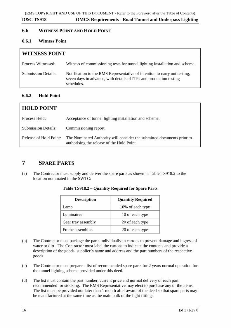
6.6 WITNESS POINT AND HOLD POINT
6.6.1 Witness Point
WITNESS POINT
Process Witnessed: Witness of commissioning tests for tunnel lighting installation and scheme.
Submission Details: Notification to the RMS Representative of intention to carry out testing, seven days in advance, with details of ITPs and production testing schedules.
6.6.2 Hold Point
HOLD POINT
Process Held: Acceptance of tunnel lighting installation and scheme.
Submission Details: Commissioning report.
Release of Hold Point: The Nominated Authority will consider the submitted documents prior to authorising the release of the Hold Point.
7 SPARE PARTS (a) The Contractor must supply and deliver the spare parts as shown in Table TS918.2 to the
location nominated in the SWTC:
Table TS918.2 – Quantity Required for Spare Parts
Description Quantity Required
Lamp 10% of each type
Luminaires 10 of each type
Gear tray assembly 20 of each type
Frame assemblies 20 of each type
(b) The Contractor must package the parts individually in cartons to prevent damage and ingress of water or dirt. The Contractor must label the cartons to indicate the contents and provide a description of the goods, supplier’s name and address and the part numbers of the respective goods.
(c) The Contractor must prepare a list of recommended spare parts for 2 years normal operation for the tunnel lighting scheme provided under this deed.
(d) The list must contain the part number, current price and normal delivery of each part recommended for stocking. The RMS Representative may elect to purchase any of the items. The list must be provided not later than 1 month after award of the deed so that spare parts may be manufactured at the same time as the main bulk of the light fittings.
16 Ed 1 / Rev 0
(RMS COPYRIGHT AND USE OF THIS DOCUMENT - Refer to the Foreword after the Table of Contents)
OMCS Requirements - Road Tunnel and Underpass Lighting D&C TS918
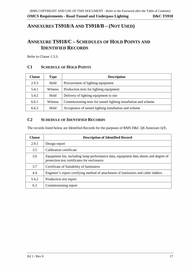
ANNEXURES TS918/A AND TS918/B – (NOT USED)
ANNEXURE TS918/C – SCHEDULES OF HOLD POINTS AND IDENTIFIED RECORDS
Refer to Clause 1.3.3.
C1 SCHEDULE OF HOLD POINTS
Clause Type Description
2.9.3 Hold Procurement of lighting equipment
5.4.1 Witness Production tests for lighting equipment
5.4.2 Hold Delivery of lighting equipment to site
6.6.1 Witness Commissioning tests for tunnel lighting installation and scheme
6.6.2 Hold Acceptance of tunnel lighting installation and scheme
C2 SCHEDULE OF IDENTIFIED RECORDS
The records listed below are Identified Records for the purposes of RMS D&C Q6 Annexure Q/E.
Clause Description of Identified Record
2.9.1 Design report
3.5 Calibration certificate
3.6 Equipment list, including lamp performance data, equipment data sheets and degree of protection test certificates for enclosures
3.7 Certificate of Suitability of luminaires
4.4 Engineer’s report certifying method of attachment of luminaires and cable ladders
5.4.2 Production test report
6.3 Commissioning report
Ed 1 / Rev 0 17
(RMS COPYRIGHT AND USE OF THIS DOCUMENT - Refer to the Foreword after the Table of Contents)
D&C TS918 OMCS Requirements - Road Tunnel and Underpass Lighting
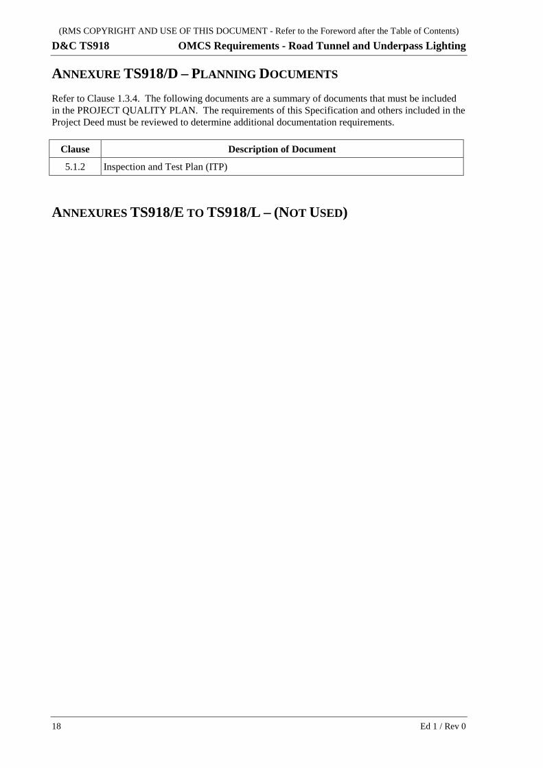
ANNEXURE TS918/D – PLANNING DOCUMENTS Refer to Clause 1.3.4. The following documents are a summary of documents that must be included in the PROJECT QUALITY PLAN. The requirements of this Specification and others included in the Project Deed must be reviewed to determine additional documentation requirements.
Clause Description of Document
5.1.2 Inspection and Test Plan (ITP)
ANNEXURES TS918/E TO TS918/L – (NOT USED)
18 Ed 1 / Rev 0
(RMS COPYRIGHT AND USE OF THIS DOCUMENT - Refer to the Foreword after the Table of Contents)
OMCS Requirements - Road Tunnel and Underpass Lighting D&C TS918
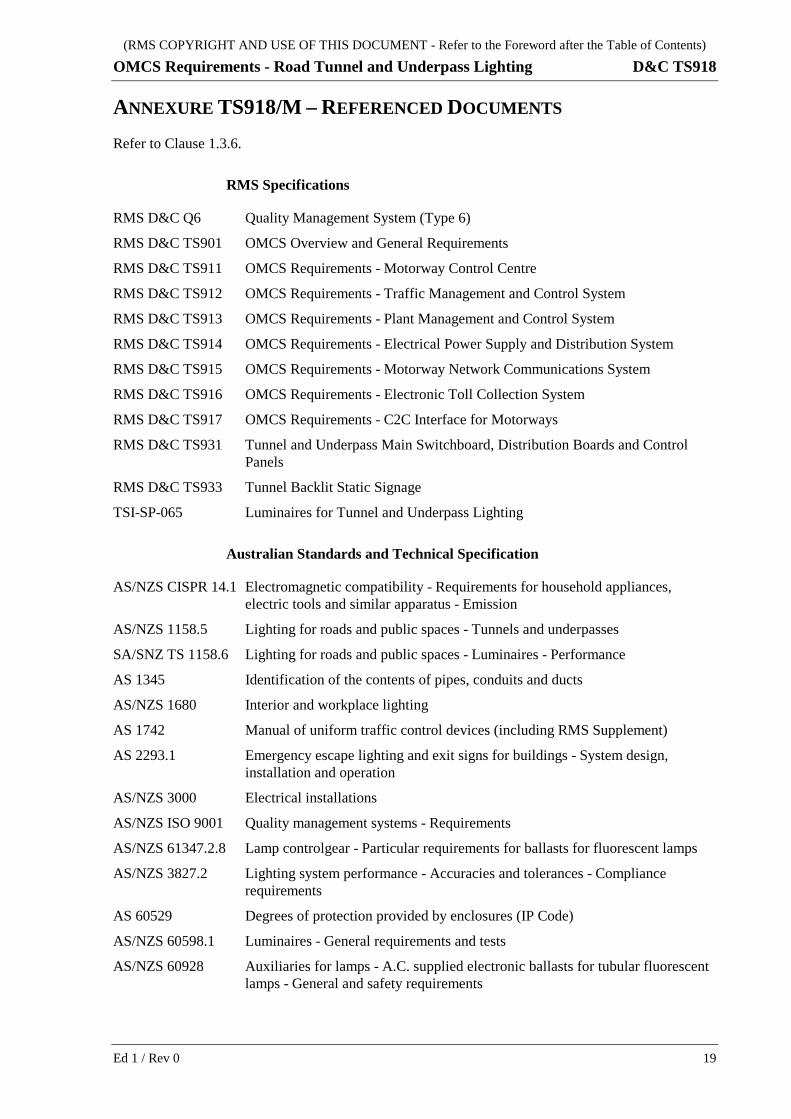
ANNEXURE TS918/M – REFERENCED DOCUMENTS Refer to Clause 1.3.6.
RMS Specifications
RMS D&C Q6 Quality Management System (Type 6)
RMS D&C TS901 OMCS Overview and General Requirements
RMS D&C TS911 OMCS Requirements - Motorway Control Centre
RMS D&C TS912 OMCS Requirements - Traffic Management and Control System
RMS D&C TS913 OMCS Requirements - Plant Management and Control System
RMS D&C TS914 OMCS Requirements - Electrical Power Supply and Distribution System
RMS D&C TS915 OMCS Requirements - Motorway Network Communications System
RMS D&C TS916 OMCS Requirements - Electronic Toll Collection System
RMS D&C TS917 OMCS Requirements - C2C Interface for Motorways
RMS D&C TS931 Tunnel and Underpass Main Switchboard, Distribution Boards and Control Panels
RMS D&C TS933 Tunnel Backlit Static Signage
TSI-SP-065 Luminaires for Tunnel and Underpass Lighting
Australian Standards and Technical Specification
AS/NZS CISPR 14.1 Electromagnetic compatibility - Requirements for household appliances, electric tools and similar apparatus - Emission
AS/NZS 1158.5 Lighting for roads and public spaces - Tunnels and underpasses
SA/SNZ TS 1158.6 Lighting for roads and public spaces - Luminaires - Performance
AS 1345 Identification of the contents of pipes, conduits and ducts
AS/NZS 1680 Interior and workplace lighting
AS 1742 Manual of uniform traffic control devices (including RMS Supplement)
AS 2293.1 Emergency escape lighting and exit signs for buildings - System design, installation and operation
AS/NZS 3000 Electrical installations
AS/NZS ISO 9001 Quality management systems - Requirements
AS/NZS 61347.2.8 Lamp controlgear - Particular requirements for ballasts for fluorescent lamps
AS/NZS 3827.2 Lighting system performance - Accuracies and tolerances - Compliance requirements
AS 60529 Degrees of protection provided by enclosures (IP Code)
AS/NZS 60598.1 Luminaires - General requirements and tests
AS/NZS 60928 Auxiliaries for lamps - A.C. supplied electronic ballasts for tubular fluorescent lamps - General and safety requirements
Ed 1 / Rev 0 19
(RMS COPYRIGHT AND USE OF THIS DOCUMENT - Refer to the Foreword after the Table of Contents)
D&C TS918 OMCS Requirements - Road Tunnel and Underpass Lighting
AS/NZS 60929 A.C. supplied electronic ballasts for tubular fluorescent lamps - Performance requirements
International Standards
CIE 88 Guide for the Lighting of Road Tunnels and Underpasses
20 Ed 1 / Rev 0


![Offsite Modular Construction System [OMCS]](https://img.pdfslide.us/doc/110x75/58819cd61a28ab1a398b46e9/offsite-modular-construction-system-omcs.jpg)