Embed Size (px)
Citation preview

Hoyer Addus VF 1000-FZ2091013
Operation ManualOM
Doc. No. OM-z2091013-01en.book
WARNINGRead and follow all safety precautions before working on or near this equipment. Read all safety precautions throughout this manual and on safety signs attached to this equipment. Failure to follow all safety precautions could result in death or serious injury.

Copyright © 2003 Tetra Pak Group
All rights reserved. No part of this document may be reproduced or copied in any form or by any means without written permission from Tetra Pak Hoyer A/S.
and all Tetra Pak products are trademarks belonging to the Tetra Pak Group.
The content of this manual is in accordance with the design and construction of the machine or equipment at the time of publishing. Tetra Pak reserves the right to introduce design modifications without prior notice.
This document was produced by:
Tetra Pak Hoyer A/S Soren Nymarks Vej 13 DK 8270 Hojbjerg Denmark
Additional copies can be ordered from Tetra Pak Parts or the nearest Tetra Pak office. When ordering additional copies, always provide the document number. This can be found in the machine specification document. It is also printed on the front cover and in the footer on each page of the manual.
Doc. No. OM-z2091013-01en.book
Issue 2008-12

This manual is valid for:
Series No./ Machine No. Sign.
OMOperation Manual
Hoyer Addus VF 1000-F Z2091013
Issue 2008-12
Doc. No. OM-z2091013-01en.book
Tetra Pak Hoyer A/S
i Introduction
ii Safety Precautions
1 Operation
A list of all optional equipment, optional kits, and rebuilding kits that this manual is valid for is found on the next page.
A list of all optional equipment, optional kits, and rebuilding kits that this manual is valid for is found on the next page.

Valid for:

Update Log for Doc. No. OM-z2091013-01en.bookThis table shows all changes made to this manual, such as kits installed and pages added or removed.
Date Installed Kit Added Pages (Doc. No.)
Removed Pages Signature

Date Installed Kit Added Pages (Doc. No.)
Removed Pages Signature

i - 1 (10)Doc. No. FI_IN3003-00en
i Introduction

i - 2 (10) Doc. No. FI_IN3003-00en
i Introduction

Table of Contents
i - 3 (10)Doc. No. FI_IN3003-00en
i Introduction
i.1 About the introduction chapter . . . . . . . . . . . . . . i - 5
i.2 Document information . . . . . . . . . . . . . . . . . . . . . i - 6i.2.1 Delivered documentation . . . . . . . . . . . . . . . . . . . . i - 6
i.3 Machine Introduction . . . . . . . . . . . . . . . . . . . . . . i - 7i.3.1 Intended use of the machine or equipment. . . . . . i - 7i.3.2 Manufacturer . . . . . . . . . . . . . . . . . . . . . . . . . . . . . . i - 7i.3.3 Service . . . . . . . . . . . . . . . . . . . . . . . . . . . . . . . . . . . i - 7
i.4 Identification . . . . . . . . . . . . . . . . . . . . . . . . . . . . . i - 8i.4.1 CE classification . . . . . . . . . . . . . . . . . . . . . . . . . . . i - 8i.4.2 Machine plate . . . . . . . . . . . . . . . . . . . . . . . . . . . . . . i - 8
i.5 Hygiene. . . . . . . . . . . . . . . . . . . . . . . . . . . . . . . . . . i - 9
i - 4 (10) Doc. No. FI_IN3003-00en
i Introduction
This page intentionally left blank

i - 5 (10)Doc. No. FI_IN3003-00en
i Introduction i.1 About the introduction chapter
i.1 About the introduction chapterRisk of serious personal injury. To ensure maximum safety, always read the chapter “Safety precautions” before operating or servicing the machine or equipment.
This chapter contains basic information about this manual and related Tetra Pak equipment.

i.2 Document information
i - 6 (10) Doc. No. FI_IN3003-00en
i Introduction
i.2 Document informationTetra Pak recommends that delivered documentation should be studied carefully and always kept available to those who will operate the machine or equipment.
It is important to keep the manual for the life of the machine or equipment and pass the manual on to any subsequent holder or user.
Tetra Pak will not be held responsible for any damage to the machine or equipment caused by not following the instructions given in this manual.
i.2.1 Delivered documentationThe documents delivered with this machine or equipment include:
• Electrical Manual (EM)The purpose of this manual is to provide the service technicians and electricians with information required for service and maintenance
• Installation Manual (IM)The purpose of this manual is to provide installation personnel with the information required for installation
• Maintenance Manual (MM)The purpose of this manual is to provide the service technicians with information required for maintenance and service
• Operation Manual (OM)The purpose of this manual is to provide the operator with information on how to handle and operate the machine or equipment before, during, and after production
• Spare Parts Catalogue (SPC)The purpose of this manual is to provide necessary information for ordering spare parts from Tetra Pak
• Technical Manual (TEM)The purpose of this manual is to provide necessary information required for installation, service and maintenance

i - 7 (10)Doc. No. FI_IN3003-00en
i Introduction i.3 Machine Introduction
i.3 Machine Introductioni.3.1 Intended use of the machine or equipment
The intended use of this Tetra Pak machine or equipment is to inject high viscosity ingredients such as rich caramel, fudge and jam into ice cream or similar products.
All other use is prohibited! Tetra Pak will not be held responsible for injury or damage if the machine or equipment is used for any other purpose.
i.3.2 ManufacturerThis Tetra Pak machine or equipment has been manufactured by:
i.3.3 ServiceIf problems are encountered when operating this machine or equipment, contact the nearest Tetra Pak centre or market company.
Contact this mail address, if you have any questions regarding the documentation:
Tetra Pak Hoyer Equipment A/SSoeren Nymarksvej 13DK-8270 HoejbjergDenmark

i.4 Identification
i - 8 (10) Doc. No. FI_IN3003-00en
i Introduction
i.4 Identificationi.4.1 CE classification
This equipment complies with the basic health and safety regulations of the European Economic Area (EEA).
i.4.2 Machine plateThe below illustration shows an example of the machine plate and its location on the machine or equipment. The machine plate carries data needed when contacting Tetra Pak concerning this specific machine or equipment.
G00001
Type : 3000 XC
Model : Hoyer KF
Machine no. : Z1181974
Year : 2002
Manufacturer : Tetra Pak Hoyer
Denmark

i - 9 (10)Doc. No. FI_IN3003-00en
i Introduction i.5 Hygiene
i.5 HygieneIce cream production, like other foodstuffs, requires high sanitary standards. That is why the strictest demands should be made on cleaning of devices and tools getting in touch with the ice cream, ingredients coating and packaging materials. In addition, the production area should be kept very clean.
Personal hygiene should also be considered as a part of the sanitary standards:
• Personal body hygiene• Headgear• Hygiene of work clothes• Hygiene of footwear• Hand hygiene
ALWAYS make sure that the detergents and disinfectants applied are approved by the local authorities.
NEVER use a detergent which chemical properties will damage the metals and alloys to be cleaned.

i.5 Hygiene
i - 10 (10) Doc. No. FI_IN3003-00en
i Introduction
This page intentionally left blank

ii - 1 (14)Doc. No. FI_SA3008-00en
ii Safety Precautions

ii - 2 (14) Doc. No. FI_SA3008-00en
ii Safety Precautions

Table of Contents
ii - 3 (14)Doc. No. FI_SA3008-00en
ii Safety Precautions
ii.1 Read the safety precautions. . . . . . . . . . . . . . . . ii - 5
ii.2 Hazard information . . . . . . . . . . . . . . . . . . . . . . . ii - 6
ii.3 Personnel requirements . . . . . . . . . . . . . . . . . . . ii - 7ii.3.1 Skilled person. . . . . . . . . . . . . . . . . . . . . . . . . . . . . ii - 7ii.3.2 Instructed person. . . . . . . . . . . . . . . . . . . . . . . . . . ii - 7
ii.4 Safety signs . . . . . . . . . . . . . . . . . . . . . . . . . . . . . ii - 8
ii.5 Location of safety signs . . . . . . . . . . . . . . . . . . . ii - 9
ii.6 Safety devices . . . . . . . . . . . . . . . . . . . . . . . . . . ii - 10ii.6.1 Emergency Stop. . . . . . . . . . . . . . . . . . . . . . . . . . ii - 10ii.6.2 Emergency stop push buttons . . . . . . . . . . . . . . ii - 10
ii.7 Personal protection. . . . . . . . . . . . . . . . . . . . . . . ii - 11ii.7.1 Hearing Protection . . . . . . . . . . . . . . . . . . . . . . . . ii - 11ii.7.2 Jewellery . . . . . . . . . . . . . . . . . . . . . . . . . . . . . . . . ii - 11
ii.8 Hazardous materials . . . . . . . . . . . . . . . . . . . . . ii - 12
ii.9 Supply systems . . . . . . . . . . . . . . . . . . . . . . . . . ii - 13ii.9.1 Electrical cabinet . . . . . . . . . . . . . . . . . . . . . . . . . ii - 13ii.9.2 Power supply . . . . . . . . . . . . . . . . . . . . . . . . . . . . ii - 14

ii - 4 (14) Doc. No. FI_SA3008-00en
ii Safety Precautions
This page intentionally left blank
ii - 5 (14)Doc. No. FI_SA3008-00en
ii Safety Precautions ii.1 Read the safety precautions
ii.1 Read the safety precautionsAll persons operating, servicing, adjusting or otherwise working with or near this machine or equipment must carefully read and follow all safety instructions in this manual and warning signs on the machine or equipment itself. Failure to do so could result in death, serious injury, and damage to the machine or equipment.
Call for medical attention immediately in case of an accident.

ii.2 Hazard information
ii - 6 (14) Doc. No. FI_SA3008-00en
ii Safety Precautions
ii.2 Hazard information
This is the “safety alert” symbol. It is used to alert about potential personal injury hazards. Obey all safety messages that follow this symbol to avoid death or injury.
The following safety alert symbols and “signal words” are used in this manu-al and on the machine or equipment itself to inform the user of hazards.
DANGERindicates an imminently hazardous situation which, if not avoided, will result in death or serious injury.
WARNINGindicates a potentially hazardous situation which, if not avoided, could result in death or serious injury.
CAUTIONindicates a potentially hazardous situation which, if not avoided, may result in minor or moderate injury. It may also be used to alert against unsafe practices.CAUTION(without the safety alert symbol) indicates a potentially hazardous situation which, if not avoided, may result in property damage.

ii - 7 (14)Doc. No. FI_SA3008-00en
ii Safety Precautions ii.3 Personnel requirements
ii.3 Personnel requirementsNote! Personnel includes all persons performing work on or near the machine or equipment.
Only skilled or instructed persons are allowed to work with the machine or equipment.
ii.3.1 Skilled personA skilled person must have relevant education and experience to enable him or her to identify hazards, analyze risks, and avoid hazards which electricity, mechanics, chemicals, and supply systems can create.
Skilled persons must meet local regulations, such as certifications and quali-fications for working with electricity, mechanical systems, and so on.
ii.3.2 Instructed personAn instructed person must be adequately advised or supervised by a skilled person to enable him or her to identify hazards, analyze risks, and avoid haz-ards which electricity, mechanics, chemicals, and supply systems on the ma-chine or equipment can create.
ii.4 Safety signs
ii - 8 (14) Doc. No. FI_SA3008-00en
ii Safety Precautions
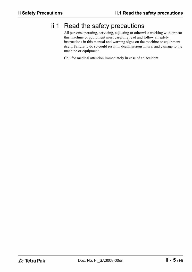
ii.4 Safety signs
WARNINGHazards without safety signs drastically increase the risk of death or serious injury. Replace all missing or damaged safety signs immediately.There are two types of safety sign
• ISO signs are used in most markets• ANSI signs are used in the US market only
The table below shows all safety signs that are located on this machine/equipment.
ISO sign ANSI sign
Hazardous voltage.Will cause death or serious injury.Disconnect power before servicing.Lockout machine.
Moving parts can crush and cut. Do not operate with guard removed. Follow lockout procedure before servicing.
DANGERHazardous voltage.Will cause deathor serious injury.
Disconnect power before
servicing.
Lockout machine.
WARNINGMoving partscan crush and cut.
Do not operate with guard
removed.
Follow lockout procedure
before serviceing.

ii - 9 (14)Doc. No. FI_SA3008-00en
ii Safety Precautions ii.5 Location of safety signs
ii.5 Location of safety signsNote! Always ensure that all safety signs on the machine or equipment are undamaged and in their correct position after installation and maintenance.
The illustration below indicates where the safety signs are located.

ii.6 Safety devices
ii - 10 (14) Doc. No. FI_SA3008-00en
ii Safety Precautions
ii.6 Safety devicesDANGER
Unshielded hazards. Never inch or run the machine or equipment if any component of the safety system is inoperative. All inoperative components of the safety system must be changed immediately.Note! Activating a safety device, such as an EMERGENCY STOP, or opening an interlocked safeguard does not switch off the power supply to the machine or equipment.
ii.6.1 Emergency StopLearn the positions of the EMERGENCY STOP devices in order to stop the machine or equipment immediately in case of an emergency situation.
To stop production the normal way, see the operation manual.
ii.6.2 Emergency stop push buttonsPush one of the EMERGENCY STOP push buttons to stop the machine or equipment immediately.
The illustration below shows an emergency stop push button. Arrow(s) indi-cates where to find them on the machine or equipment.
G01258

ii - 11 (14)Doc. No. FI_SA3008-00en
ii Safety Precautions ii.7 Personal protection
ii.7 Personal protectionNote! Personal protection required when handling hazardous materials is specified for each substance, see the section “Hazardous materials”.
ii.7.1 Hearing Protection
WARNINGHazardous noise level. Risk of impaired hearing. Wear hearing protection.
CAUTIONHazardous noise level. Risk of impaired hearing. Hearing protection is recommended.
ii.7.2 Jewellery
WARNINGRisk of entanglement. No jewellery such as rings, watches, bracelets, or necklaces may be worn when performing work on or near the machine or equipment.

ii.8 Hazardous materials
ii - 12 (14) Doc. No. FI_SA3008-00en
ii Safety Precautions
ii.8 Hazardous materials
WARNINGContact with chemicals can cause injury and illnesses. Always follow the manufacturer’s instructions when handling chemical products.Always make sure that
• the showers work• an eyewash device, movable or wall-mounted, is available and
operational• additional washing facilities are nearby
Note! Learn the positions of all washing facilities in order to act without delay in case of an accident.

ii - 13 (14)Doc. No. FI_SA3008-00en
ii Safety Precautions ii.9 Supply systems
ii.9 Supply systemsii.9.1 Electrical cabinet
DANGERHazardous voltage. Electric shock will cause death or serious injury. The power supply disconnecting device must be turned OFF and secured with a lock before any service is carried out inside the electrical cabinet.Note! The key to the lock must be removed by the service technician or the electrician, and retained in his/her possession until all work is completed.
Make sure that the electrical cabinet doors are locked after performing any work in the electrical cabinet.
An arrow in the illustration below indicates the location of an electrical cabi-net.

ii.9 Supply systems
ii - 14 (14) Doc. No. FI_SA3008-00en
ii Safety Precautions
ii.9.2 Power supply
DANGERHazardous voltage and moving machinery. The power supply disconnecting device must be turned OFF and secured with a lock before any service is carried out.Note! The key to the lock must be removed by the service technician or the electrician, and retained in his/her possession until all work is completed.
Certain maintenance procedures require supply systems to be turned on. These exceptions are clearly stated in the maintenance manual.
The illustration below shows the power supply disconnecting device and the arrow indicates its location.

1 - 1 (52)Doc. No. VF-PanelView3001-00en
1 Operation
1 - 2 (52) Doc. No. VF-PanelView3001-00en
1 Operation

Table of Contents
1 - 3 (52)Doc. No. VF-PanelView3001-00en
1 Operation
1.1 Functional description . . . . . . . . . . . . . . . . . . . . 1 - 5
1.2 Main groups of equipment . . . . . . . . . . . . . . . . . 1 - 6
1.3 Control panel . . . . . . . . . . . . . . . . . . . . . . . . . . . . 1 - 71.3.2 Foil keyboard . . . . . . . . . . . . . . . . . . . . . . . . . . . . . 1 - 81.3.3 Touch screen . . . . . . . . . . . . . . . . . . . . . . . . . . . . . 1 - 91.3.4 Screen descriptions. . . . . . . . . . . . . . . . . . . . . . . 1 - 12
1.3.4.1 HMI - Display . . . . . . . . . . . . . . . . . . . . . . . . . . . . . 1 - 121.3.4.2 HMI - Units . . . . . . . . . . . . . . . . . . . . . . . . . . . . . . . 1 - 131.3.4.3 Production mode . . . . . . . . . . . . . . . . . . . . . . . . . . 1 - 141.3.4.4 Info - Dosing. . . . . . . . . . . . . . . . . . . . . . . . . . . . . . 1 - 151.3.4.5 Info - Heating . . . . . . . . . . . . . . . . . . . . . . . . . . . . . 1 - 161.3.4.6 Info - Info . . . . . . . . . . . . . . . . . . . . . . . . . . . . . . . . 1 - 171.3.4.7 Recipe . . . . . . . . . . . . . . . . . . . . . . . . . . . . . . . . . . . 1 - 181.3.4.8 Production . . . . . . . . . . . . . . . . . . . . . . . . . . . . . . . 1 - 191.3.4.9 General - Dosing . . . . . . . . . . . . . . . . . . . . . . . . . . 1 - 21
1.3.4.10 General - Agitator. . . . . . . . . . . . . . . . . . . . . . . . . . 1 - 231.3.4.11 General - Heat . . . . . . . . . . . . . . . . . . . . . . . . . . . . 1 - 241.3.4.12 General - Freezers . . . . . . . . . . . . . . . . . . . . . . . . . 1 - 251.3.4.13 Maintenance - Dosing unit . . . . . . . . . . . . . . . . . . 1 - 261.3.4.14 Alarm - active . . . . . . . . . . . . . . . . . . . . . . . . . . . . . 1 - 271.3.4.15 Alarm - historic . . . . . . . . . . . . . . . . . . . . . . . . . . . 1 - 281.3.4.16 Setup - Machine . . . . . . . . . . . . . . . . . . . . . . . . . . . 1 - 291.3.4.17 Setup - Configure. . . . . . . . . . . . . . . . . . . . . . . . . . 1 - 311.3.4.18 Setup - Weighing system . . . . . . . . . . . . . . . . . . . 1 - 331.3.4.19 Setup - Regulation control . . . . . . . . . . . . . . . . . . 1 - 34
1.4 Alarms and troubleshooting. . . . . . . . . . . . . . . 1 - 361.4.1 Warnings. . . . . . . . . . . . . . . . . . . . . . . . . . . . . . . . 1 - 361.4.2 Alarms. . . . . . . . . . . . . . . . . . . . . . . . . . . . . . . . . . 1 - 38
1.5 Preparation. . . . . . . . . . . . . . . . . . . . . . . . . . . . . 1 - 41
1.6 Start. . . . . . . . . . . . . . . . . . . . . . . . . . . . . . . . . . . 1 - 42

Table of Contents
1 - 4 (52) Doc. No. VF-PanelView3001-00en
1 Operation
1.6.1 Automatic. . . . . . . . . . . . . . . . . . . . . . . . . . . . . . . 1 - 421.6.2 Manual . . . . . . . . . . . . . . . . . . . . . . . . . . . . . . . . . 1 - 42
1.7 Checks . . . . . . . . . . . . . . . . . . . . . . . . . . . . . . . . 1 - 431.7.1 Refilling of ingredients . . . . . . . . . . . . . . . . . . . . 1 - 43
1.8 Change of product . . . . . . . . . . . . . . . . . . . . . . . 1 - 44
1.9 Hold . . . . . . . . . . . . . . . . . . . . . . . . . . . . . . . . . . . 1 - 45
1.10 Stop . . . . . . . . . . . . . . . . . . . . . . . . . . . . . . . . . . . 1 - 461.10.1 Automatic. . . . . . . . . . . . . . . . . . . . . . . . . . . . . . . 1 - 461.10.2 Manual . . . . . . . . . . . . . . . . . . . . . . . . . . . . . . . . . 1 - 46
1.11 Cleaning . . . . . . . . . . . . . . . . . . . . . . . . . . . . . . . 1 - 471.11.1 Manual cleaning procedure . . . . . . . . . . . . . . . . 1 - 471.11.2 Exterior cleaning . . . . . . . . . . . . . . . . . . . . . . . . . 1 - 471.11.3 Deposits . . . . . . . . . . . . . . . . . . . . . . . . . . . . . . . . 1 - 471.11.4 Dosing unit. . . . . . . . . . . . . . . . . . . . . . . . . . . . . . 1 - 471.11.5 Cleaning detergents . . . . . . . . . . . . . . . . . . . . . . 1 - 481.11.6 Hygiene . . . . . . . . . . . . . . . . . . . . . . . . . . . . . . . . 1 - 51

1 - 5 (52)Doc. No. VF-PanelView3001-00en
1 Operation 1.1 Functional description
1.1 Functional descriptionThe Hoyer Addus VF 1000 automatic variegate feeder is designed for the continuous and accurate injection of fruit pieces, nuts, candies and other free flowing granulates into ice cream or similar products.
The variegate feeder is a self-contained unit ready to be connected to power and ice cream supply. From the hopper the ingredient is dosed by means of a helical dosing screw into the lamella pump, which gently delivers the ingredient into the ice cream stream. Further mixing is done in the inline mixer before the ice cream passes through the outlet of the feeder.

1.2 Main groups of equipment
1 - 6 (52) Doc. No. VF-PanelView3001-00en
1 Operation
1.2 Main groups of equipmentThe VF 1000 variegate feeder consists of 3 main elements:
• A dosing unit for dosing of ingredient (1)• An electrical cabinet with control panel (2)
1 Dosing unit2 Electrical cabinet with control panel

1 - 7 (52)Doc. No. VF-PanelView3001-00en
1 Operation 1.3 Control panel
1.3 Control panelThe VF 1000 is equipped with a Siemens MP370 touch screen interface (1) and a foil keyboard (2).
1 Touch screen2 Foil keyboard

1.3 Control panel
1 - 8 (52) Doc. No. VF-PanelView3001-00en
1 Operation
1.3.2 Foil keyboardThe keyboard is used for start and stop of various functions.
A light above the start/stop buttons indicates if a function has been started (green light) or stopped.
1 StopStop production
2 ProductionStart production
3 HoldHold production
4 ManualManual production
5 Dosing Start/stop of dosing
6 AgitatorStart/stop of agitatorIf dosing is stopped, the agitator also stops to prevent fragile ingredients to be damaged.
7 TempStart/stop the temperature control of the tank
8 ResetResetting of alarm - a green light will flash, if resetting is needed.Solid green: The machine is resetting and operation is blocked.
1 - 9 (52)Doc. No. VF-PanelView3001-00en
1 Operation 1.3 Control panel
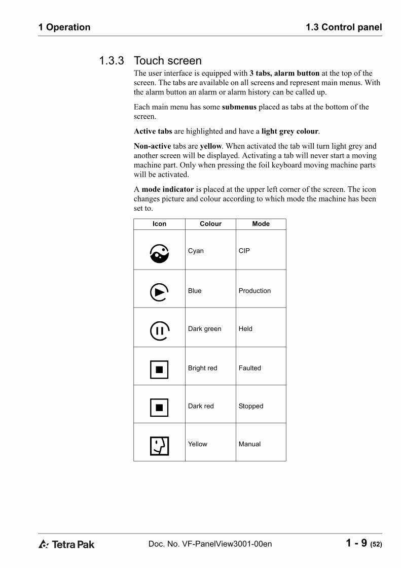
1.3.3 Touch screenThe user interface is equipped with 3 tabs, alarm button at the top of the screen. The tabs are available on all screens and represent main menus. With the alarm button an alarm or alarm history can be called up.
Each main menu has some submenus placed as tabs at the bottom of the screen.
Active tabs are highlighted and have a light grey colour.
Non-active tabs are yellow. When activated the tab will turn light grey and another screen will be displayed. Activating a tab will never start a moving machine part. Only when pressing the foil keyboard moving machine parts will be activated.
A mode indicator is placed at the upper left corner of the screen. The icon changes picture and colour according to which mode the machine has been set to.
Icon Colour Mode
Cyan CIP
Blue Production
Dark green Held
Bright red Faulted
Dark red Stopped
Yellow Manual

1.3 Control panel
1 - 10 (52) Doc. No. VF-PanelView3001-00en
1 Operation
An information/alarm bar is placed at the upper right corner of the screen. The info bar displays alarms, production messages and in stop mode also maintenance alarms. In case of more than one alarm/message at a time, the alarm/message will be displayed one after another for approx. 2 sec. each.
G04124
Mode
indicator Information/alarm textAlarm
button
Tabs
(main menus)
(active = light grey)
(non-active = yellow)
Tabs
(middle menus)
Tabs
(submenus)

1 - 11 (52)Doc. No. VF-PanelView3001-00en
1 Operation 1.3 Control panel
Warning lamp
The warning lamp (1) alerts the operator on distance that the variegate feeder needs attention. There are two kinds of signals:
• Flashing. A production warning, used when the hopper needs refilling. Alternatively, other warnings that do not force the variegate feeder to stop.
• Constant. A critical warning that forces all or some machine parts to stop. Production will be interrupted and some warning situations may require skilled personnel.
Safety switch alarms can be reset when the safety cover(s) are put back in place.
1 Warning lamp

1.3 Control panel
1 - 12 (52) Doc. No. VF-PanelView3001-00en
1 Operation
1.3.4 Screen descriptions1.3.4.1 HMI - Display
1 Login buttonWrite user ID and password. This will give access to the setup screens and to the panel configuration.ID: HOYERPassword: 1111Automatic logoff after 5 minutes.
2 Change language
3 Date adjustment
4 Clock adjustment
G04125
1 2
3
4

1 - 13 (52)Doc. No. VF-PanelView3001-00en
1 Operation 1.3 Control panel
1.3.4.2 HMI - Units
This screen gives the selection between US units and SI units.
G04126

1.3 Control panel
1 - 14 (52) Doc. No. VF-PanelView3001-00en
1 Operation
1.3.4.3 Production modeDosing, agitator, feed pump and inline mixer can be started and stopped from any screen, while presets only can be set from the production screen. Below screen Production - from here it is possible to adjust production presets and see actual data.
Below screen Settings - from here production parameters can be adjusted, for instance the selection between the dosing modes “constant speed”, “constant flow” and “constant ratio”.
G04127
G04128

1 - 15 (52)Doc. No. VF-PanelView3001-00en
1 Operation 1.3 Control panel
1.3.4.4 Info - Dosing
Shows the flow for the last hour of production.
G04129
1.3 Control panel
1 - 16 (52) Doc. No. VF-PanelView3001-00en
1 Operation
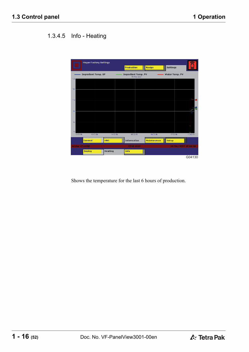
1.3.4.5 Info - Heating
Shows the temperature for the last 6 hours of production.
G04130

1 - 17 (52)Doc. No. VF-PanelView3001-00en
1 Operation 1.3 Control panel
1.3.4.6 Info - Info
Shows the different status parameters on the machine.
G04131

1.3 Control panel
1 - 18 (52) Doc. No. VF-PanelView3001-00en
1 Operation
1.3.4.7 Recipe
From the above Recipe screen it is possible to select a previously stored product. All presets, settings and production mode will be loaded, saving the adjustment time.
1 SaveSaves the current product in the current recipe.
2 Save asSaves the current product in a new recipe. The actual recipe will not change.
3 LoadLoads the selected recipe.
G04132
1
2
3

1 - 19 (52)Doc. No. VF-PanelView3001-00en
1 Operation 1.3 Control panel
1.3.4.8 Production
From the production screen the dosing, agitator, preset ingredient flow/amount/speed percentage can be adjusted by the arrow below the preset bars. The functions can be turned on/off by the start/stop buttons on the foil keyboard.
Actual ingredient flow/amount/speed percentage are shown as the wide blue bar.
G04133
1 2 3 4

1.3 Control panel
1 - 20 (52) Doc. No. VF-PanelView3001-00en
1 Operation
1 WeightThe light blue bar indicates the relative weight between the “Max. ingredient” and the “Refill warning” of ingredient weight.In order to get the best resolution, the “Refill warning” and “Max. ingredient” must be set on “Settings-General-Dosing” to fit the actual ingredient in the hopper.When the bar drops below 0% (disappears) the alarm lamp will flash, and the info “Refill hopper” will indicate a warning to the operator that the ingredient level is low, and the hopper needs a refill.The absolute weight is indicated at the bottom of the bar.
2 Dosing
Constant flow [Kg/h] - [lb/h]When “Production mode: constant flow” on “Settings-General-Dosing” is selected, the dosing flow is preset, and the VF will regulate the flow by means of the dosing screw speed.The actual dosing screw speed percentage will be shown as a readout.
Constant ratio [g/l] - [oz/10 gal] - [lb/100 gal] - [lb/gal]When “Production mode: constant ratio” is selected, the amount of ingredient vs. ice cream flow is preset, and the VF will regulate the ratio, by means of the dosing screw speed, according to actual ice cream flow, communicated from the ice cream freezer.The actual auger speed percentage will be shown as a readout.This production mode is only available if the VF is equipped with a communication link to the freezer(s), and the actual communication has been chosen in the machine setup.
Constant speed [%]When “Production mode: constant speed” is selected, the dosing screw speed is controlled directly by the operator, and no regulation is active, and the dosing screw speed is constant. The actual flow will be shown as a readout.
3 AgitatorThe agitator speed is variable, and can be set between 0 and 100% relative, min. speed = 0%, max speed = 100%.Only use the agitator if the product needs agitation, or a different product needs to be blended in the hopper. Also, it is recommended to use as low a speed as possible if the ingredient is fragile.The agitator can be set to “intermitted” mode, and the “on” and “off” intervals can be set on agitator settings.
4 HeatingPreset the ingredient temperature between 0°C (32°F) and a selected max. temperature from the heat settings.The actual ingredient temperature is also shown.

1 - 21 (52)Doc. No. VF-PanelView3001-00en
1 Operation 1.3 Control panel
1.3.4.9 General - Dosing
1 Dosing controlThe chosen dosing mode, the dosing preset value, will change according to the production mode chosen.
Constant flow: The preset is the ingredient flow/hour. The variegate feeder automatically regulates the dosing screw speed, in order to minimise the difference between preset flow and actual flow.Constant ratio: The preset is the amount of ingredient / ice cream unit. The variegate feeder reads the ice cream flow and dynamically calculates the actual ingredient flow preset.Constant ratio cannot be chosen unless the variegate feeder is equipped and set up with a communication link to the ice cream freezer(s).Constant speed: The dosing screw constant speed is set directly without the regulation active. This mode should only be used if it is impossible to run a difficult ingredient in constant flow or ratio, or during maintenance. The hopper level alarms are still active.
G04134
1
2
3
45
6
7
8

1.3 Control panel
1 - 22 (52) Doc. No. VF-PanelView3001-00en
1 Operation
2 TareWhen changing the dosing screw, the dosing weight must be tared in order to have the right ingredient alarm levels. The tare is saved in the recipe so that tare needs only to be carried out the first time provided the same dosing screw is always used.The tare must only be used on an empty hopper, equipped with dosing screw, agitator and hopper grill. It is only possible to activate tare, if the machine is empty and out of production.
3 Reset accumulatedThe accumulated flow is shown and can be reset. Please note that the count deviates to the actual, as the count is theoretically during refill.
4 Max. ingredientAlarm limit for activating “Max. ingredient” can be used to inform the operator or an automatic refill system, that the hopper is filled.The parameter also scales the “ingredient % bar” 100%.
5 Refill warningAlarm limit for activating “Refill warning” and the alarm lamp. Informing the operator or an automatic refill system, that the hopper must be refilled.The parameter also scales the “Ingredient % bar” 0%.
6 Dosing start speedWhen the dosing is started, the variegate feeder does not know the flow rate at a given speed, due to different ingredient mass volume. The variegate feeder will always start on the start speed until it is able to sample a stable flow, or when “start speed timeout” occurs.For further details, see screen description “Regulation parameters”.
7 Max. dosing pressureSet the alarm for dosing pressure.
8 Dosing modeSelect the dosing mode (only on dual pump machines).Pump 1Only pump 1 will be used for dosing.Pump 2Only pump 2 will be used for dosing.Both pumpsBoth pumps will be used for dosing. Please note that the pumps will be running at the same speed. This does not mean that they will dose the same amount of ingredient, but the sum of both pumps will be correct.

1 - 23 (52)Doc. No. VF-PanelView3001-00en
1 Operation 1.3 Control panel
1.3.4.10 General - Agitator
1 Agitator modeAgitator working modes:OFF: The agitator is always off.Continuos: The agitator is always on.Intermittent: The agitator starts and stops according to the ON and OFF intervals shown in the two next parameters. Can be used if the ingredient is very fragile but needs agitation.
2 Agitator ON timeThe “on” interval, if “Agitator mode: intermittent”
3 Agitator OFF timeThe “off” interval, if “Agitator mode: intermittent”
G04135
1
2
3

1.3 Control panel
1 - 24 (52) Doc. No. VF-PanelView3001-00en
1 Operation
1.3.4.11 General - Heat
1 Heating modeEnable/disable heating control.
2 Ingredient temperatureShows the actual temperature of the ingredient.
3 Water temperatureShows the actual temperature of the water.
4 Max. ingredient temperatureSet a max. limit for the ingredient temperature. This parameter also scales the “heating bar” max.
5 Max. water temperatureSet a max. limit for the water temperature. This parameter prevents the heating coil from overheating. Must be set below 70°C (158°F).
G04136
1
4
5
2
3

1 - 25 (52)Doc. No. VF-PanelView3001-00en
1 Operation 1.3 Control panel
1.3.4.12 General - Freezers(Only available if Communication is selected).
Analogue communication with freezers can be deselected after the customer’s choice.
1 Select freezersToggle reading of freezer flow on/off.
2 Total flow from freezersThe total flow from all freezers. Readout only.
3 Max. flow scaleSet the max. flow from each freezer. This value must correspond to the max. possible cream flow from the freezer. It is only possible to change the value when logged in.
4 Min. flow startSet the min. total flow that must be present before dosing can be started. It is only possible to change the value when logged in.
G04137
1
1
1
2
1
3
3
3
3
4

1.3 Control panel
1 - 26 (52) Doc. No. VF-PanelView3001-00en
1 Operation
1.3.4.13 Maintenance - Dosing unit
1 In this column the preset hour values are shown. The values are set from factory, but can be changed if requested.
2 In this column the actual running hours are shown.
3 In this column the actual running hours can be reset. Note that it can only be reset when preset hour count has been exceeded.
G04138
1 2 3

1 - 27 (52)Doc. No. VF-PanelView3001-00en
1 Operation 1.3 Control panel
1.3.4.14 Alarm - active
On this screen all active alarms are shown.
G04139
To remove the banner, push the Acknowledge button on the banner. Then push the Reset button on the push button panel.
The alarm is shown on a banner and can appear on all screens.

1.3 Control panel
1 - 28 (52) Doc. No. VF-PanelView3001-00en
1 Operation
1.3.4.15 Alarm - historic
On this screen the history of all alarms is shown.
To scroll between the different alarm histories, use the up/down arrows.
G04140

1 - 29 (52)Doc. No. VF-PanelView3001-00en
1 Operation 1.3 Control panel
1.3.4.16 Setup - Machine
When then machine is taken into use the first time all parameters may be blank, so make sure the setup is correct and then push "New setup". All setup screens are password protected. Login is done under Settings-HMI-Display.
G04141
1
2
3
4
5
7
11
8
9
10
6

1.3 Control panel
1 - 30 (52) Doc. No. VF-PanelView3001-00en
1 Operation
1 TypeHere you determine the identity of the machine.
2 Serial numberThe first 3 numbers are determined by the type, the last 4 have to be entered according to the number on the machine.
3 OperationAutomatic is for VF 1000-F.
4 VoltageSelect the base voltage.
5 FrequencySelect the base frequency.
6 New setupOnly to be used on very first start-up or if setup screen turns out to be blank.NOTE! On new setup you must tara the weighing system again, if the machine type is changed.
7 Weight systemIf the machine has a weighing system, select YES. If a problem occurs on the weighing system it can be deselected here.
8 CommunicationSelect communication type.
9 Pump systemSelect single or double pump system.
10 CIPSelect CIP mode.
11 Load default settingsFactory settings are loaded.NOTE! You must tara the weighing system again.

1 - 31 (52)Doc. No. VF-PanelView3001-00en
1 Operation 1.3 Control panel
1.3.4.17 Setup - Configure
1 Download DeviceNet config.Only to be used if the DeviceNet scanner has been changed.
2 Setup DeviceNet nodesOnly to be used if the machine setup has been changed.
3 VFD selectSelect frequency converter for setup.
4 Download factory parametersFactory parameters are locked and cannot be changed.
5 Upload actual parametersUse for receiving of actual parameters if parameters have been changed.
6 Download stored parametersDownload parameters which have been uploaded.
G04142
2
1 3
4
5
6

1.3 Control panel
1 - 32 (52) Doc. No. VF-PanelView3001-00en
1 Operation
Shows the motor parameters from the frequency converter.
1 Gear ratioSet the gear ratio from the shaft to the motor axle.
G04143
1
1 - 33 (52)Doc. No. VF-PanelView3001-00en
1 Operation 1.3 Control panel
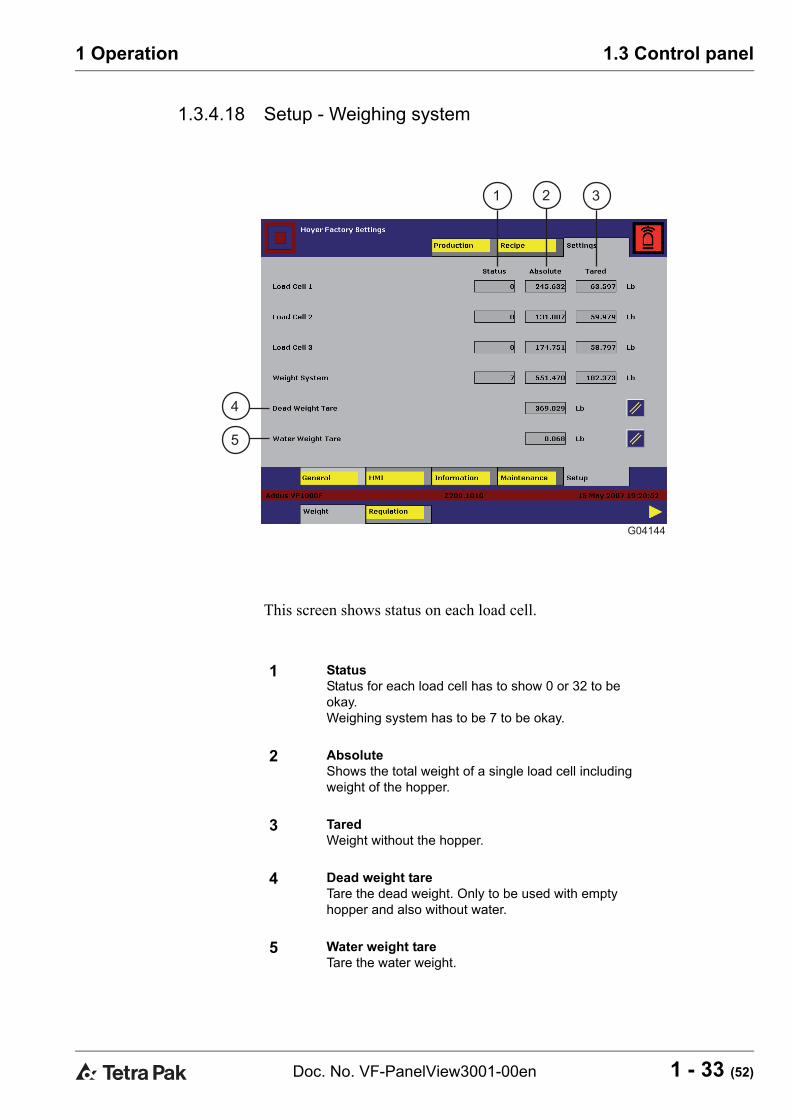
1.3.4.18 Setup - Weighing system
This screen shows status on each load cell.
1 StatusStatus for each load cell has to show 0 or 32 to be okay.Weighing system has to be 7 to be okay.
2 AbsoluteShows the total weight of a single load cell including weight of the hopper.
3 TaredWeight without the hopper.
4 Dead weight tareTare the dead weight. Only to be used with empty hopper and also without water.
5 Water weight tareTare the water weight.
G04144
1 2 3
4
5

1.3 Control panel
1 - 34 (52) Doc. No. VF-PanelView3001-00en
1 Operation
1.3.4.19 Setup - Regulation control
All regulation parameters are used with the "Loss In Weight" automatic dosing regulation, active when parameter "Dosing Control" on screen Settings-General-Dosing is set to "Constant flow" or "Constant ratio". If set to "Constant speed" the dosing regulator will be idle.
The "Speed" described refers to the "Dosing pump speed"
Note! These settings should in most cases be left to factory default, and may be different to the ones shown on the screen. Only to be adjusted by qualified personnel.
Default factory settings can be seen in the electrical diagrams, or can be restored by pressing "Load default settings" on screen "Settings-Setup-Machine".
G04145
1
2
3
4
5
6
7
8
9

1 - 35 (52)Doc. No. VF-PanelView3001-00en
1 Operation 1.3 Control panel
1 Feedback time adaptation Automatic adjustment of the Feedback time in order to give the fastest stable feedback to the regulator.[YES] The feedback time is automatically adjusted (default).[NO] The feedback time will be a fixed value, which can be manually adjusted.
2 Feedback timeThe feedback filter sample time. The higher value the more stable but slower response. The parameter is set in seconds.If "Feedback Time Adaptation" is set to YES, this value will be adapted automatically and the parameter is only readout of the actual feedback time.
3 Start speed adaptation:When the regulator starts it has to sample an amount of ingredient dosing in order to find the flow rate at a known dosing screw speed. When the regulator have run a hopper batch, it will try to adapt that speed, so it can be saved in the recipes and give a correct start speed the next time the product is run.[YES] The start speed will be adapted at each hopper batch (default). If the dosing preset is changed with more than 10%, the start speed will be set to the value in "Default start speed" parameter.[NO] The start speed will be a fixed value that can manually be set in the parameter "Dosing start speed" on screen "Settings-General-Dosing".
4 Default start speedThis parameter is only active if "Start speed adaptation is set to [YES].If the dosing preset is changed with more than 10%, the "Dosing start speed" will be set to this value.
5 Start step free rangeWhen the regulator has found the flow rate at the start speed, it will calculate the needed speed preset and step to this.[YES] The regulator can make an initial start step within the speed range (10 - 90%) (default).[NO] The regulator is limited to step within a relative step limit table.
6 Step dead zoneThe regulator will make speed steps in the "feedback time" + 1 sec. intervals, if the relative deviation between the set point and the actual dosing value is higher than the dead-zone percentage. If the deviation is within the "Step dead zone", the regulator will track the speed to ex.The parameter is set in relative percentage (%).
7 Dosing stop alarmStops the dosing and change hold. Only activated if dosing has been active and the dosing has been less than the parameter "Dosing stop below" in a speed dependent time. Used to detect if the hopper runs dry or the funnel is blocked.[YES] The function is activated (default).[NO] The function is deactivated.
8 Dosing stop belowThe threshold dosing flow "Dosing stop alarm" uses when detecting if there is a dosing stop or not. The parameter should be set so high that it does not see the dosing screw vibrations as a false ingredient flow. The parameter is set as dosing flow in kg/h or lb/h and can only be adjusted if the "Dosing stop alarm is set to YES.
9 Regulation during refill warningWhen the level in the hopper is low, the flow feedback can become uneven, causing an unstable regulator output. To avoid this situation the regulation can be suspended when the ingredient level is below the "Refill warning". (Set on the dosing setting screen).[YES] The regulator will be running when refill warning.[NO] The regulator will be held when refill warnings have appeared (default).

1.4 Alarms and troubleshooting
1 - 36 (52) Doc. No. VF-PanelView3001-00en
1 Operation
1.4 Alarms and troubleshootingAlarms are divided into two categories “Warnings” and “Alarms”.
• “Warnings” are production/maintenance information to the operator. The warning does not interrupt the operation of the machine (except “weight sys. timeout”). Some warnings in need of immediate operator response will cause the alarm lamp to flash.
• “Alarms” will cause all or part of the machine to stop and will interrupt the production. The alarm lamp will remain yellow.
1.4.1 Warnings
Warning Cause Remedy<<STOPPED>> Machine is not running. Ready to start.<<RESETTING>> Machine is resetting. Wait until reset.<<READY IN CONSTANT FLOW MODE>>
Ready for production in constant flow mode.
Push start buttons.
<<READY IN CONSTANT RATIO MODE>>
Ready for production in constant ratio mode.
Push start buttons.
<<READY IN CONSTANT SPEED MODE>>
Ready for production in constant speed mode.
Push start buttons.
<<CONSTANT FLOW PRODUCTION>>
Machine is running production in constant flow mode.
Push stop buttons to stop production.
<<CONSTANT RATIO PRODUCTION>>
Machine is running production in constant ratio mode.
Push stop buttons to stop production.
<<CONSTANT SPEED PRODUCTION>>
Machine is running production in constant speed mode.
Push stop buttons to stop production.
<<STOPPED BY FAULT>>
The machine has stopped by fault. All moving parts of the machine will be stopped and cannot be operated.
Refer to alarm banner or alarm historic on display for troubleshooting.
<<MAX INGREDIENT WEIGHT>>
Max. ingredient weight has been exceeded according to max. level on dosing settings screen.
Change max. level or do not overfill the hopper.
<<REFILL HOPPER>> The ingredient level is below alarm level on dosing settings screen.
Refill the hopper.
<<LOW SPEED RANGE>>
If actual screw speed is below 10%.
Change gear ratio on dosing pump.
<<HIGH SPEED RANGE>>
If actual screw speed is above 90%.
Change gear ratio on dosing pump.
<<WATER WEIGHT TARING>>
Water weight is not tared. Must be done each time the water is changed. Refer to manual.

1 - 37 (52)Doc. No. VF-PanelView3001-00en
1 Operation 1.4 Alarms and troubleshooting
<<DOSING MIN.>> Dosing speed is 0.1%. Change screw or gear ratio on dosing screw.
<<DOSING MAX.>> Dosing speed is 100%. Change screw or gear ratio on dosing screw.
<<HOLD (FAULT)>> The machine has been put on hold by fault. Dosing and agitation will be forced to stop. The feed pump and blender will continue to run.
Refer to alarm banner or alarm historic on display for troubleshooting.
<<HOLD (OPERATOR)>> The machine is put on hold by the operator.
Push start.
<<HOLD (EXTERNAL)>> (Optional). The machine is put on hold by external signal.
Restart is possible locally/externally.
<<HOLD (ICE CREAM MIN.)>>
(Optional). The machine is put on hold due to low flow from freezers only active in constant ratio mode.
<<HOLD (DOSING STOP)>>
The machine is put on hold due to stop of the dosing screw.
If no weight loss has been detected for X sec. (according to speed). Refill hopper or clean funnel for obsticals.
Warning Cause Remedy

1.4 Alarms and troubleshooting
1 - 38 (52) Doc. No. VF-PanelView3001-00en
1 Operation
1.4.2 AlarmsRefer to the electrical drawings for component position numbers.
Common for all the alarms:
• The alarm lamp will flash constantly.• After the fault has been removed, the reset button must be pressed to
remove the alarm.• The light next to the reset button will flash when a reset is needed.
WARNINGOnly trained maintenance personnel must carry out all alarms that cannot be reset without opening the electrical cabinet.
Alarm Cause Remedy<<EMERGENCY STOP>> The emergency stop
button has been pressed or power has been removed from the machine.The machine will be forced into stop mode and cannot be operated until the alarm has been reset.
Release the emergency stop (if pressed).
<<DOSING UNIT OVERLOAD>>
The circuit breaker for the dosing unit has tripped.Dosing and agitation will be forced to stop - the feed pump and blender can still be operated.
Open the electrical cabinet and turn on the circuit breaker.Close the electrical cabinet and turn on the machine.
<<HOPPER SAFETY SWITCH>>
The hopper grill has been detected removed while not in stop mode.Dosing and agitation will be forced to stop - the feed pump and blender can still be operated.
Put the hopper grill back in place.
<<DOSING MOTOR TOO HOT>>
The internal thermal motor protection has detected motor overheat.Dosing and agitation will be forced to stop - the feed pump and blender can still be operated.
Wait until the motor cools down and the alarm can be reset.

1 - 39 (52)Doc. No. VF-PanelView3001-00en
1 Operation 1.4 Alarms and troubleshooting
<<DOSING DRIVE FAULT>>
The variable motor drive has detected a fault. Dosing and agitation will be forced to stop - the feed pump and blender can still be operated.
Open the electrical cabinet. Connect the machine and enter production mode. When the drive is connected, the display will be flashing. Press "stop/reset" on the drive, followed by "start".Close the electrical cabinet.
<<AGITATOR MOTOR TOO HOT>>
The internal thermal motor protection has detected motor overheat.Agitation will be forced to stop the dosing, feed pump and blender can still be operated.
Wait until the motor cools down and the alarm can be reset.
<<AGITATOR DRIVE FAULT>>
The variable motor drive has detected a fault. Agitation will be forced to stop the dosing - feed pump and blender can still be operated.
Open the electrical cabinet. Connect the machine and enter production mode. When the drive is installed, the display will flash. Press "stop/reset" on the drive, followed by "start".Close the electrical cabinet.
<<MACHINE IS NOT SET UP>>
The machine is not set up and will not be able to run.
Go to the screen “Machine setup” and put in the parameters from the Hoyer drawings and then make a new setup.
<<PLC HAS BEEN IN STOP>>
The PLC has been in stop or power has been switched off.
Push Reset.
<<LOW BATTERY IN PLC>>
Battery backup in the CPU is low. The machine can run as normal, but if main power is switched off, the CPU will loose its program.
Change battery.
<<GENERAL DEVICE NET ERROR>>
The device net is down and the machine will not be able to run.
Look on the device net scanner for troubleshooting information code.
<<DOSING DEVICE NET ERROR>>
The device net scanner has detected a problem on the dosing drive. Dosing and agitation will be forced to stop. The feed pump and blender can still be operated.
Look on the device net scanner for troubleshooting information code.
Alarm Cause Remedy

1.4 Alarms and troubleshooting
1 - 40 (52) Doc. No. VF-PanelView3001-00en
1 Operation
<<AGITATOR DEVICE NET ERROR>>
The device net scanner has detected a problem on the agitator drive. Agitation will be forced to stop. Dosing, feed pump and blender can still be operated.
Look on the device net scanner for troubleshooting information code.
<<WEIGHING UNIT DEVICE NET ERROR>>
The device net scanner has detected a problem on the weighing unit. The machine will be able to operate in constant speed mode.
Look on the device net scanner for troubleshooting information code. Disable the weighing system to continue production in constant speed mode.
<<LOAD CELL 1 ERROR>>
The weighing system has detected a fault on the load cell.
Change the load cell. Until then disable the weighing system to continue production in constant speed mode.
<<LOAD CELL 2 ERROR>>
The weighing system has detected a fault on the load cell.
Change the load cell. Until then disable the weighing system to continue production in constant speed mode.
<<LOAD CELL 3 ERROR>>
The weighing system has detected a fault on the load cell.
Change the load cell. Until then disable the weighing system to continue production in constant speed mode.
<<WEIGHT SYSTEM FAULT>>
There is a fault on the weighing transmitter.
Change the weighing transmitter. Until then disable the weighing system to continue production in constant speed mode.
<<DEAD WEIGHT TARING>>
The hopper is not tared. Refer to the manual.
<<DOSING STOP>> The dosing screw has stopped.
If no weight loss has been detected for X sec., (according to speed). Refill hopper or funnel for obsticals.
Alarm Cause Remedy

1 - 41 (52)Doc. No. VF-PanelView3001-00en
1 Operation 1.5 Preparation
1.5 PreparationThe VF variegate feeder is designed for dosing of high viscous ingredients such as rich caramel, fudge and jam.
Certain ingredients tend to agglutinate at a high relative humidity or high temperatures. This may result in uneven dosing.
The following precautions may improve such dosing conditions:
• Cool down the ingredients.• Only fill the hopper partially.• Use another type of dosing screw.
WARNINGThe access doors must always be correctly fitted when the variegate feeder is in operation.
WARNINGNever place fingers/other body parts in the ingredients hopper, when the variegate feeder is connected to mains.

1.6 Start
1 - 42 (52) Doc. No. VF-PanelView3001-00en
1 Operation
1.6 Start1.6.1 Automatic
a) Press Production (2) to go to pre-production.b) Press Production (2) again to go to production mode. Dosing and agitator
start.
1.6.2 Manuala) Press Manual (4) to enable manual mode.b) Start dosing by pressing (5).c) If agitation is needed, start the agitator by pressing (6).d) Press Manual (4) again to exit manual mode.
1 Stop2 Production3 Hold4 Manual5 Dosing 6 Agitator7 Temp8 Reset

1 - 43 (52)Doc. No. VF-PanelView3001-00en
1 Operation 1.7 Checks
1.7 Checks1.7.1 Refilling of ingredients
The VF 1000 is provided with a refill warning lamp (1). In case the warning is activated, refill ingredients.
1 Warning lamp
1.8 Change of product
1 - 44 (52) Doc. No. VF-PanelView3001-00en
1 Operation
1.8 Change of productIt is recommended that the VF 1000 is cleaned in connection with change of ingredient.

1 - 45 (52)Doc. No. VF-PanelView3001-00en
1 Operation 1.9 Hold
1.9 Holda) Press Hold (3) to hold production. Dosing stops and the agitator is still
running.b) Press Production (2) again to restart dosing.
1 Stop2 Production3 Hold4 Manual5 Dosing 6 Agitator7 Temp8 Reset

1.10 Stop
1 - 46 (52) Doc. No. VF-PanelView3001-00en
1 Operation
1.10 Stop1.10.1 Automatic
a) Press Stop (1) to stop dosing and agitator.
1.10.2 Manuala) Stop dosing by pressing (5).b) If the agitator is on, stop the agitator by pressing (6).
1 Stop2 Production3 Hold4 Manual5 Dosing 6 Agitator7 Temp8 Reset

1 - 47 (52)Doc. No. VF-PanelView3001-00en
1 Operation 1.11 Cleaning
1.11 Cleaning
WARNINGDisconnect the mains supply before preparing for cleaning: Turn main switch to position "0" and then lock the switch with a padlock.
WARNINGHigh temperatures. During cleaning or operation with media warmer than 50°C there is a risk of burning, if the lamella feed pump, mixer outlet or mixer inlet pipes are touched.
1.11.1 Manual cleaning procedurea) Prerinse with warm water.b) Manual cleaning with brush and sponge by using a suitable detergent.c) Final rinse with potable water.Note! After each cleaning and disinfection a final rinse with potable water is required (legal demands).
1.11.2 Exterior cleaningTo keep a shiny surface a sporadic acidic foam cleaning is required.
a) Prerinse with water.b) Acid foam cleaning.c) Final rinse with water.
1.11.3 DepositsOnce or twice every season deposits of calcium salts should be removed.
a) Disassemble mixer and lamella pump.b) Wash the individual parts with weak acids (for instance acetic acid or
citric acid, pH 3.0 - 4.5, max. 100 ppm).c) Rinse immediately and thoroughly with cold water.d) Dry parts.
1.11.4 Dosing unitRemove the agitator and dosing screw from the dosing unit and clean all the parts manually.

1.11 Cleaning
1 - 48 (52) Doc. No. VF-PanelView3001-00en
1 Operation
1.11.5 Cleaning detergentsThe below table contains examples of detergents to be used when cleaning the machine with water.
CAUTIONDo not use acids or chlorine containing detergents apart from the exceptions described below. Chlorine exposes the rotor, beater and scraper blades to pitting corrosion and rusting; it also exposes the chrome layer to pitting corrosion. Acid attacks chrome layer and nickel/nickel bronze.
Addus VF 1000 variegate feeder
Area / Equipment P3-Product Product characteristics Application
conc. [%] temp. [°C]
time [min.]
P3-tresolin ST
manual cleaning, neutral cleaner with disinfecting properties
1.0 - 2.0 30 - 50 10 - 30
P3-topax 12 low alkaline manual clean-ing
1.0 - 2.0 30 - 50 10 - 30
P3-topax 52 acid foam cleaner 2.0 - 3.0 30 - 50 10 - 15
Quadet SU 133
manual cleaning, low alka-line cleaner with disinfect-ing properties
1.0 - 2.0 30 - 50 10 - 30
Sanol SU 120
neutral manual cleaning 1.0 - 2.0 30 - 50 10 - 30
Acigel SU 631
acid foamgel cleaner 2.0 - 3.0 30 - 50 10 - 15

1 - 49 (52)Doc. No. VF-PanelView3001-00en
1 Operation 1.11 Cleaning
*) There may be authorities which do not permit the use of quaternary ammonium compounds.
CAUTIONCaution when P3-triquart is applied in connection with production of cultured products such as frozen yogurt.
Hand cleaning and disinfection. Shoes/boots disinfection
Area / Equipment P3-Product Product characteristics Application
conc. [%] temp. [°C] time [min.]
Mansoft hand cleaner 100 (3 ml) room temp. 0.5
Manodes hand disinfectant 100 (3 ml) room temp. 0.5
P3-triquart*) neutral disinfectant, bath application
2.0 - 3.0 room temp. 10 - 15
Leverline Bac
hand cleaner 100 (3 ml) room temp. 0.5
Leverline Med
hand disinfectant 100 (3 ml) room temp. 0.5
Divosan QC*)
neutral disinfectant, bath application
0.5 - 2.0 room temp.

1.11 Cleaning
1 - 50 (52) Doc. No. VF-PanelView3001-00en
1 Operation
The detergents should not be applied until the material safety data sheets and product data sheets have been read and understood. These documents can be requested from the local Ecolab or JohnsonDiversey agent respectively.
The local agent can be identified by contacting one of the following offices:
Ecolab GmbH & Co. OHGReisholzer Werfstr. 38-4240589 DüsseldorfGermanyTel: +49 211 98930
Ecolab Center370 N. Wabasha St.St. PaulMinnesota 55102USATel: +1 612 293 2233
Ecolab Ltd.15/F, Lu Plaza2 Wing Yip StreetKwun Tong, KowloonHong KongTel: +852 2341 4202
JohnsonDiversey F&BR&DMallaustrasse 50-5668219 MannheimGermanyTel: +49 621 87570
JohnsonDiverseyWTB AmsterdamAirport/Tower B, 8th floor1118 BH LuchthavenSchipholNetherlandsTel: +31 20 3164500
JohnsonDiversey R&D3630 East Kemper RoadSharonvilleCincinnatiOhioUSATel: +1 516 8296918

1 - 51 (52)Doc. No. VF-PanelView3001-00en
1 Operation 1.11 Cleaning
1.11.6 HygieneIce cream production, like other foodstuffs, requires high sanitary standards. That is why the strictest demands should be made on cleaning of devices and tools getting in touch with the ice cream, ingredients coating and packaging materials. In addition, the production area should be kept very clean.
Personal hygiene should also be considered as a part of the sanitary standards:
• Personal body hygiene• Headgear• Hygiene of work clothes• Hygiene of footwear• Hand hygiene
ALWAYS make sure that the detergents and disinfectants applied are approved by the local authorities.
NEVER use a detergent which chemical properties will damage the metals and alloys to be cleaned.

1.11 Cleaning
1 - 52 (52) Doc. No. VF-PanelView3001-00en
1 Operation
This page intentionally left blank


This page intentionally left blank


![PAK-A-PUNCH & KEY BLANK REFERENCE - ABsupply.net · 2015-11-18 · pak-a-punch & key blank reference ... valet an1-an9282 x9/73vb pak-v1 v01 acces pak-90v 90deg ... [-p] pak-v1 v01](https://img.pdfslide.us/doc/110x75/5b3896967f8b9a5a518d9b59/pak-a-punch-key-blank-reference-2015-11-18-pak-a-punch-key-blank-reference.jpg)