Embed Size (px)
Citation preview

CEAM015001
Operation & MaintenanceManual
DUMP TRUCK
SERIAL NUMBERS A30733 & UP
®

NOTES:
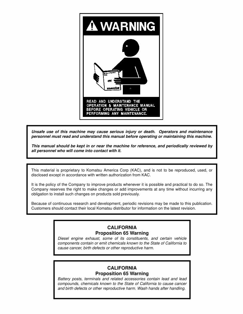
CALIFORNIAProposition 65 Warning
Battery posts, terminals and related accessories contain lead and leadcompounds, chemicals known to the State of California to cause cancerand birth defects or other reproductive harm. Wash hands after handling.
CALIFORNIAProposition 65 Warning
Diesel engine exhaust, some of its constituents, and certain vehiclecomponents contain or emit chemicals known to the State of California tocause cancer, birth defects or other reproductive harm.
This material is proprietary to Komatsu America Corp (KAC), and is not to be reproduced, used, ordisclosed except in accordance with written authorization from KAC.
It is the policy of the Company to improve products whenever it is possible and practical to do so. TheCompany reserves the right to make changes or add improvements at any time without incurring anyobligation to install such changes on products sold previously.
Because of continuous research and development, periodic revisions may be made to this publication.Customers should contact their local Komatsu distributor for information on the latest revision.
Unsafe use of this machine may cause serious injury or death. Operators and maintenancepersonnel must read and understand this manual before operating or maintaining this machine.
This manual should be kept in or near the machine for reference, and periodically reviewed byall personnel who will come into contact with it.

NOTES
CEHQ000700 - Komatsu America International Company 12/99
EMISSION CONTROL WARRANTY
EMISSION CONTROL WARRANTY STATEMENT (APPLIES TO CANADA ONLY)
1. Products Warranted
Komatsu America International Company, Komatsu Mining Systems Inc. and Komatsu Utility Corporation (collectively “Komatsu”) produce and/or market products under brand names of Komatsu, Dresser, Dressta, Haulpak and Galion. This emissions warranty applies to new engines bearing the Komatsu name installed in these products and used in Canada in machines designed for industrial off-highway use. This warranty applies only to these engines produced on or after January 1, 2000. This warranty will be administered by Komatsu distribution in Canada.
2. Coverage
Komatsu warrants to the ultimate purchaser and each subsequent purchaser that the engine is designed, built and equipped so as to conform, at the time of sale by Komatsu, with all U.S. Federal emission regulations applicable at the time of manufacture and that it is free from defects in workmanship or material which would cause it not to meet these regulations within five years or 3,000 hours of operation, whichever occurs first, as measured from the date of delivery of the engine to the ultimate purchaser.
3. Limitations
Failures, other than those resulting from defects in materials or workmanship, are not covered by this warranty. Komatsu is not responsible for failures or damage resulting from what Komatsu determines to be abuse or neglect, including, but not limited to: operation without adequate coolant or lubricants; over fueling; over speeding; lack of maintenance of lubricating, cooling or intake systems; improper storage, starting, warm-up, run-in or shutdown practices; unauthorized modifications of the engine. Komatsu is also not responsible for failures caused by incorrect fuel or by water, dirt or other contaminants in the fuel. Komatsu is not responsible for non-engine repairs, “downtime” expense, related damage, fines, all business costs or other losses resulting from a warrantable failure. KOMATSU IS NOT RESPONSIBLE FOR INCIDENTAL OR CONSEQUENTIAL DAMAGES.
This warranty, together with the express commercial warranties, are the sole warranties of Komatsu. THERE ARE NO OTHER WARRANTIES, EXPRESS OR IMPLIED, OR OF MERCHANTABILITY OR FITNESS FOR A PARTICUALR PURPOSE.
GARANTIE SUR LE CONTRÔLE DES ÉMISSIONS ÉNONCÉ DE GARANTIE SUR LE CONTRÔLE DES ÉMISSIONS (APPLICABLE AU CANADA SEULEMENT): 1. Produits garantis:
Komatsu America International Company, Komatsu Mining Systems Inc. et Komatsu Utility Corporation (collectivement Komatsu) produisent et/ou font la mise en marché de produits portant les noms de marque Komatsu, Dresser, Dressta, Haulpak et Galion. Cette garantie sur les émissions s’applique à tous les nouveaux moteurs portant le nom Komatsu, installés dans ces produits et utilisés au Canada dans des machines conçues pour utilisation industrielle non-routière. Cette garantie s’applique seulement sur les moteurs produits à partir du 1er Janvier 2000. Cette garantie sera administrée par la distribution de Komatsu au Canada.
2. Couverture:
Komatsu garantit à l’acheteur ultime et chaque acheteur subséquent que le moteur est conçu, construit et équipé en toute conformité, au moment de la vente par Komatsu, avec toutes les Réglementations fédérales américaines sur les émissions applicables au moment de la fabrication et qu’il est exempt de défauts de construction ou de matériaux qui auraient pour effet de contrevenir à ces réglementations en dedans de 5 ans ou 3000 heures d’opération, mesuré à partir de la date de livraison du moteur au client ultime.
3. Limitations:
Les bris, autres que ceux résultant de défauts de matériaux ou de construction, ne sont pas couverts par cette Garantie. Komatsu n’est pas responsable pour bris ou dommages résultant de ce que Komatsu détermine comme étant de l’abus ou négligence, incluant mais ne se limitant pas à: l’opération sans lubrifiants ou agent refroidissants adéquats; la suralimentation d’essence; la survitesse; le manque d’entretien des systèmes de lubrification, de refroidissement ou d’entrée; de pratiques non-propices d’entreposage, de mise en marche, de réchauffement, de conditionnement ou d’arrêt; les modifications non-autorisées du moteur. De plus, Komatsu n’est pas responsable de bris causés par de l’essence inadéquate ou de l’eau, des saletés ou autres contaminants dans l’essence. Komatsu n’est pas responsable des réparations non-reliées au moteur, des dépenses encourues suite aux temps d’arrêts, des dommages relatifs, amendes, et de tout autre coût d’affaires ou autres pertes résultant d’un bris couvert par la garantie.
KOMATSU N’EST PAS RESPONSABLE DES INCIDENTS OU DOMMAGES CONSÉQUENTS. Cette garantie, ainsi que les garanties expresses commerciales, sont les seules garanties de Komatsu. IL N’Y A AUCUNE AUTRE GARANTIE, EXPRESSE OU SOUS -ENTENDUE, MARCHANDABLE OU PROPICE A UNE UTILISATION PARTICULIÈRE.
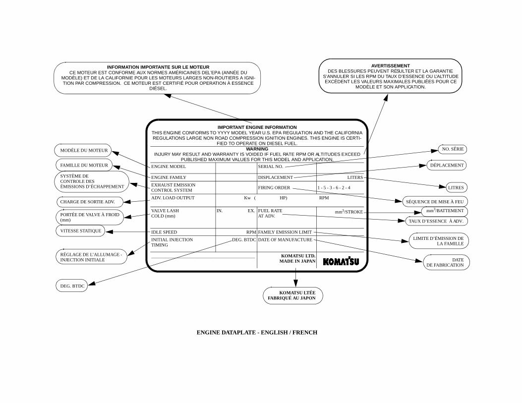
AVERTISSEMENTS PEUVENT RÉSULTER ET LA GARANTIE RPM DU TAUX D’ESSENCE OU L’ALTITUDE ALEURS MAXIMALES PUBLIÉES POUR CE DÈLE ET SON APPLICATION.
NO. SÉRIE
DÉPLACEMENT
LITRES
SÉQUENCE DE MISE À FEU
mm3/BATTEMENT
TAUX D’ESSENCE À ADV.
LIMITE D’ÉMISSION DELA FAMILLE
DATEDE FABRICATION
INFORMATION IMPORTANTE SUR LE MOTEURCE MOTEUR EST CONFORME AUX NORMES AMÉRICAINES DE L’EPA (ANNÉE DU
MODÈLE) ET DE LA CALIFORNIE POUR LES MOTEURS LARGES NON-ROUTIERS A IGNI-TION PAR COMPRESSION. CE MOTEUR EST CERTIFIÉ POUR OPERATION À ESSENCE
DIÉSEL.
DES BLESSURES’ANNULER SI LESEXCÈDENT LES V
MO
IMPORTANT ENGINE INFORMATION THIS ENGINE CONFORMS TO YYYY MODEL YEAR U.S. EPA REGULATION AND THE CALIFORNIAREGULATIONS LARGE NON ROAD COMPRESSION IGNITION ENGINES. THIS ENGINE IS CERTI-
FIED TO OPERATE ON DIESEL FUEL.
MODÈLE DU MOTEUR WARNINGINJURY MAY RESULT AND WARRANTY IS VOIDED IF FUEL RATE RPM OR ALTITUDES EXCEED
PUBLISHED MAXIMUM VALUES FOR THIS MODEL AND APPLICATION.FAMILLE DU MOTEUR ENGINE MODEL SERIAL NO.
SYSTÈME DE CONTROLE DES ÉMISSIONS D’ÉCHAPPEMENT
ENGINE FAMILY DISPLACEMENT LITERS
EXHAUST EMISSIONCONTROL SYSTEM
FIRING ORDER 1 - 5 - 3 - 6 - 2 - 4
CHARGE DE SORTIE ADV.ADV. LOAD OUTPUT
Kw ( HP) RPM
PORTÉE DE VALVE À FROID (mm)
VALVE LASHCOLD (mm)
IN. EX. FUEL RATE AT ADV.
mm3/STROKE
VITESSE STATIQUE IDLE SPEED RPM FAMILY EMISSION LIMIT
INITIAL INJECTION TIMING
DEG. BTDC DATE OF MANUFACTURE
RÉGLAGE DE L’ALLUMAGE - INJECTION INITIALE
_____________________________________________ KOMATSU LTD.MADE IN JAPAN
DEG. BTDC
KOMATSU LTÉEFABRIQUÉ AU JAPON
ENGINE DATAPLATE - ENGLISH / FRENCH
OM1046 10/04 Introduction - Section 10Page 10-1
FOREWORD
This Manual is written for use by the operator and/or the service technician and is designed to help these personsto become fully knowledgeable of the truck and all its systems in order to keep it operating safely and efficiently.
All operators and maintenance personnel should read and understand the materials in this manual before operat-ing the truck or performing maintenance and/or operational checks on the truck. All safety notices, warnings andcautions should be understood and followed when operating or accomplishing repairs on the truck.
The first section is an Introduction to the manual and contains a Table of Contents to locate specific areas of inter-est. Other sections include Safety, Operation, Maintenance, Specifications, and Optional Equipment.
The illustrations used in this manual are TYPICAL of the component shown and may not be an exact reproductionof what is found on the truck.
A product identification plate is located on the frame in front of the right side front wheel and designates the TruckModel Number, Product Identification Number (vehicle serial number), and Maximum G.V.W. (Gross VehicleWeight) rating.
The KOMATSU Truck Model designation consists of three numbers and one letter (i.e. 830E). The three numbersrepresent the basic truck model. The letter “M” designates a Mechanical drive and the letter “E” designates anElectrical wheelmotor drive system.
The Product Identification Number (vehicle serial number) contains information which will identify the original man-ufacturing bill of material for this unit. This complete number will be necessary for proper ordering of many serviceparts and/or warranty consideration.
The Gross Vehicle Weight (GVW) is what determines the load on the drive train, frame, tires, and other compo-nents. The vehicle design and application guidelines are sensitive to the total maximum Gross Vehicle Weight(GVW) and this means the TOTAL WEIGHT: the Empty Vehicle Weight + the fuel & lubricants + the payload.
To determine allowable payload: Service all lubricants for proper level and fill fuel tank of empty truck (which includes all accessories, body liners,tailgates, etc.) and then weigh truck. Record this value and subtract from the GVW rating. The result is the allow-able payload.
NOTE: Accumulations of mud, frozen material, etc. become a part of the GVW and reduces allowable payload. Tomaximize payload and to keep from exceeding the GVW rating, these accumulations should be removed as oftenas practical.
Exceeding the allowable payload will reduce expected life of truck components.
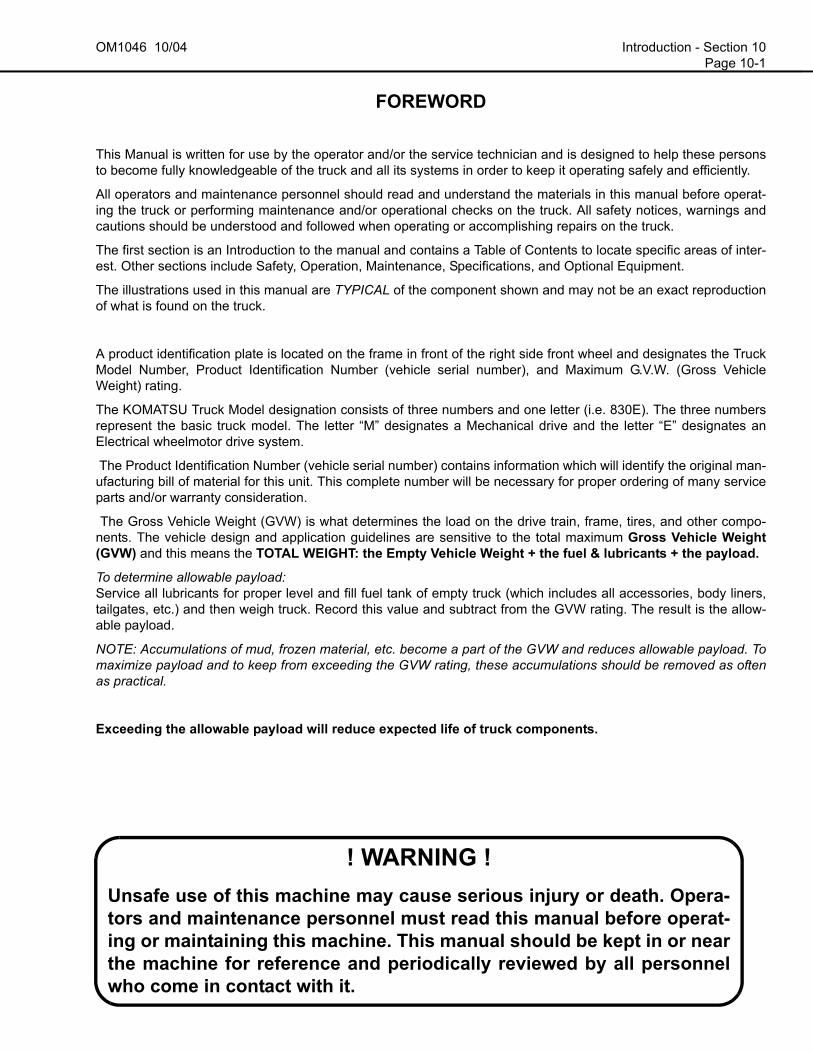
! WARNING !Unsafe use of this machine may cause serious injury or death. Opera-tors and maintenance personnel must read this manual before operat-ing or maintaining this machine. This manual should be kept in or nearthe machine for reference and periodically reviewed by all personnelwho come in contact with it.

Introduction - Section 10 10/04 OM1046Page 10-2
This “ALERT” symbol is used with the signal words, “DANGER”, “WARNING”, and “CAUTION” in this man-ual to alert the reader to hazards arising from improper operating and maintenance practices.
“DANGER” identifies a specific potential hazard WHICH WILL RESULT IN EITHER INJURY OR DEATH if proper precautions are not taken.
“WARNING” identifies a specific potential hazard WHICH MAY RESULT IN EITHER INJURY OR DEATH if proper precautions are not taken.
“CAUTION” is used for general reminders of proper safety practices OR to direct the reader’s attention to avoid unsafe or improper practices which may result in damage to the equipment.
OM1046 10/04 Introduction - Section 10Page 10-3
TABLE OF CONTENTS
SUBJECT - - - - - - - - - - - - - - - - - - - - - - - - - - - - - - - - - - - - - - - - - - - - - - - SECTION / PAGE
FOREWARD 10-1“Alerts” Page - a description of DANGER, WARNING, and CAUTION symbols. . . . . . . . . . . . . . . . . . . . . 10-2
TABLE OF CONTENTS . . . . . . . . . . . . . . . . . . . . . . . . . . . . . . . . . . . . . . . . . . . . . . . . . . . . . . . . . . . . . . . . . 10-3Truck Model Illustration . . . . . . . . . . . . . . . . . . . . . . . . . . . . . . . . . . . . . . . . . . . . . . . . . . . . . . . . . . . . . . 10-10
ABOUT THIS MANUAL . . . . . . . . . . . . . . . . . . . . . . . . . . . . . . . . . . . . . . . . . . . . . . . . . . . . . . . . . . . . . . . . 10-11STANDARD CHARTS AND TABLES . . . . . . . . . . . . . . . . . . . . . . . . . . . . . . . . . . . . . . . . . . . . . . . . . . . . . . . 12-1
SAFETY 20-1Safety Rules . . . . . . . . . . . . . . . . . . . . . . . . . . . . . . . . . . . . . . . . . . . . . . . . . . . . . . . . . . . . . . . . . . . . . . . 20-1Safety Features . . . . . . . . . . . . . . . . . . . . . . . . . . . . . . . . . . . . . . . . . . . . . . . . . . . . . . . . . . . . . . . . . . . . . 20-1Clothing And Personal Items . . . . . . . . . . . . . . . . . . . . . . . . . . . . . . . . . . . . . . . . . . . . . . . . . . . . . . . . . . . 20-1Unauthorized Modification . . . . . . . . . . . . . . . . . . . . . . . . . . . . . . . . . . . . . . . . . . . . . . . . . . . . . . . . . . . . . 20-1Leaving The Operator’s Seat . . . . . . . . . . . . . . . . . . . . . . . . . . . . . . . . . . . . . . . . . . . . . . . . . . . . . . . . . . 20-2Mounting And Dismounting . . . . . . . . . . . . . . . . . . . . . . . . . . . . . . . . . . . . . . . . . . . . . . . . . . . . . . . . . . . . 20-2Fire Prevention For Fuel And Oil . . . . . . . . . . . . . . . . . . . . . . . . . . . . . . . . . . . . . . . . . . . . . . . . . . . . . . . . 20-2Precautions With High Temperature Fluids . . . . . . . . . . . . . . . . . . . . . . . . . . . . . . . . . . . . . . . . . . . . . . . . 20-3Asbestos Dust Hazard Prevention . . . . . . . . . . . . . . . . . . . . . . . . . . . . . . . . . . . . . . . . . . . . . . . . . . . . . . . 20-3Prevention Of Injury By Work Equipment . . . . . . . . . . . . . . . . . . . . . . . . . . . . . . . . . . . . . . . . . . . . . . . . . 20-3Fire Extinguisher And First Aid Kit . . . . . . . . . . . . . . . . . . . . . . . . . . . . . . . . . . . . . . . . . . . . . . . . . . . . . . . 20-3Precautions When Using ROPS . . . . . . . . . . . . . . . . . . . . . . . . . . . . . . . . . . . . . . . . . . . . . . . . . . . . . . . . 20-4Precautions For Attachments . . . . . . . . . . . . . . . . . . . . . . . . . . . . . . . . . . . . . . . . . . . . . . . . . . . . . . . . . . 20-4Precautions For Starting Machine . . . . . . . . . . . . . . . . . . . . . . . . . . . . . . . . . . . . . . . . . . . . . . . . . . . . . . . 20-4
PRECAUTIONS DURING OPERATION . . . . . . . . . . . . . . . . . . . . . . . . . . . . . . . . . . . . . . . . . . . . . . . . . . . . 20-5Safety Is Thinking Ahead . . . . . . . . . . . . . . . . . . . . . . . . . . . . . . . . . . . . . . . . . . . . . . . . . . . . . . . . . . . . . . 20-5Safety At The Worksite . . . . . . . . . . . . . . . . . . . . . . . . . . . . . . . . . . . . . . . . . . . . . . . . . . . . . . . . . . . . . . . 20-5Fire Prevention . . . . . . . . . . . . . . . . . . . . . . . . . . . . . . . . . . . . . . . . . . . . . . . . . . . . . . . . . . . . . . . . . . . . . 20-5Preparing For Operation . . . . . . . . . . . . . . . . . . . . . . . . . . . . . . . . . . . . . . . . . . . . . . . . . . . . . . . . . . . . . . 20-5Ventilation In Enclosed Areas . . . . . . . . . . . . . . . . . . . . . . . . . . . . . . . . . . . . . . . . . . . . . . . . . . . . . . . . . . 20-5In Operator’s Cab - Before Starting The Engine . . . . . . . . . . . . . . . . . . . . . . . . . . . . . . . . . . . . . . . . . . . . 20-6Mirrors, Windows, And Lights . . . . . . . . . . . . . . . . . . . . . . . . . . . . . . . . . . . . . . . . . . . . . . . . . . . . . . . . . . 20-6
OPERATING THE MACHINE . . . . . . . . . . . . . . . . . . . . . . . . . . . . . . . . . . . . . . . . . . . . . . . . . . . . . . . . . . . . 20-6When Starting The Engine . . . . . . . . . . . . . . . . . . . . . . . . . . . . . . . . . . . . . . . . . . . . . . . . . . . . . . . . . . . . . 20-6Truck Operation - General . . . . . . . . . . . . . . . . . . . . . . . . . . . . . . . . . . . . . . . . . . . . . . . . . . . . . . . . . . . . . 20-6Check When Traveling In Reverse . . . . . . . . . . . . . . . . . . . . . . . . . . . . . . . . . . . . . . . . . . . . . . . . . . . . . . 20-7Traveling . . . . . . . . . . . . . . . . . . . . . . . . . . . . . . . . . . . . . . . . . . . . . . . . . . . . . . . . . . . . . . . . . . . . . . . . . . 20-7Traveling On Slopes . . . . . . . . . . . . . . . . . . . . . . . . . . . . . . . . . . . . . . . . . . . . . . . . . . . . . . . . . . . . . . . . . 20-8Ensure Good Visibility . . . . . . . . . . . . . . . . . . . . . . . . . . . . . . . . . . . . . . . . . . . . . . . . . . . . . . . . . . . . . . . . 20-8
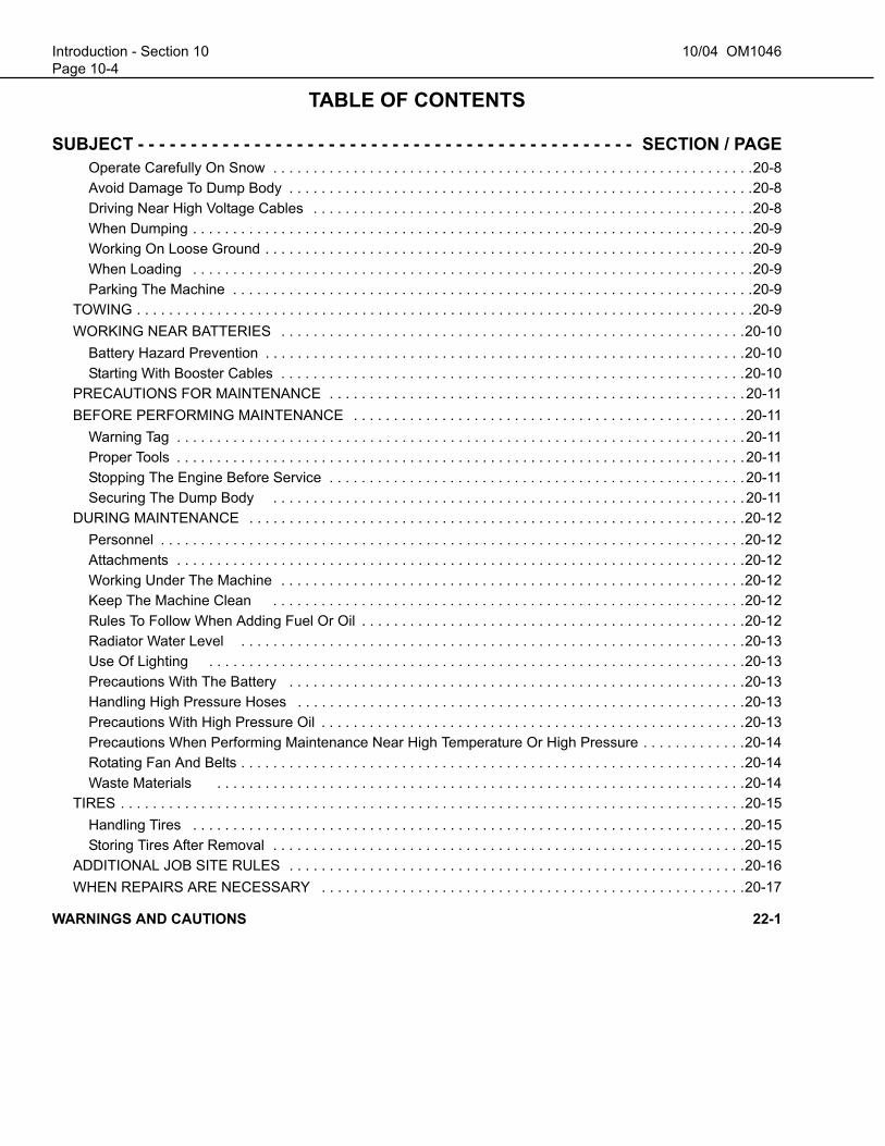
Introduction - Section 10 10/04 OM1046Page 10-4
TABLE OF CONTENTS
SUBJECT - - - - - - - - - - - - - - - - - - - - - - - - - - - - - - - - - - - - - - - - - - - - - - - SECTION / PAGEOperate Carefully On Snow . . . . . . . . . . . . . . . . . . . . . . . . . . . . . . . . . . . . . . . . . . . . . . . . . . . . . . . . . . . .20-8Avoid Damage To Dump Body . . . . . . . . . . . . . . . . . . . . . . . . . . . . . . . . . . . . . . . . . . . . . . . . . . . . . . . . . .20-8Driving Near High Voltage Cables . . . . . . . . . . . . . . . . . . . . . . . . . . . . . . . . . . . . . . . . . . . . . . . . . . . . . . .20-8When Dumping . . . . . . . . . . . . . . . . . . . . . . . . . . . . . . . . . . . . . . . . . . . . . . . . . . . . . . . . . . . . . . . . . . . . . .20-9Working On Loose Ground . . . . . . . . . . . . . . . . . . . . . . . . . . . . . . . . . . . . . . . . . . . . . . . . . . . . . . . . . . . . .20-9When Loading . . . . . . . . . . . . . . . . . . . . . . . . . . . . . . . . . . . . . . . . . . . . . . . . . . . . . . . . . . . . . . . . . . . . . .20-9Parking The Machine . . . . . . . . . . . . . . . . . . . . . . . . . . . . . . . . . . . . . . . . . . . . . . . . . . . . . . . . . . . . . . . . .20-9
TOWING . . . . . . . . . . . . . . . . . . . . . . . . . . . . . . . . . . . . . . . . . . . . . . . . . . . . . . . . . . . . . . . . . . . . . . . . . . . . .20-9WORKING NEAR BATTERIES . . . . . . . . . . . . . . . . . . . . . . . . . . . . . . . . . . . . . . . . . . . . . . . . . . . . . . . . . .20-10
Battery Hazard Prevention . . . . . . . . . . . . . . . . . . . . . . . . . . . . . . . . . . . . . . . . . . . . . . . . . . . . . . . . . . . .20-10Starting With Booster Cables . . . . . . . . . . . . . . . . . . . . . . . . . . . . . . . . . . . . . . . . . . . . . . . . . . . . . . . . . .20-10
PRECAUTIONS FOR MAINTENANCE . . . . . . . . . . . . . . . . . . . . . . . . . . . . . . . . . . . . . . . . . . . . . . . . . . . .20-11BEFORE PERFORMING MAINTENANCE . . . . . . . . . . . . . . . . . . . . . . . . . . . . . . . . . . . . . . . . . . . . . . . . .20-11
Warning Tag . . . . . . . . . . . . . . . . . . . . . . . . . . . . . . . . . . . . . . . . . . . . . . . . . . . . . . . . . . . . . . . . . . . . . . .20-11Proper Tools . . . . . . . . . . . . . . . . . . . . . . . . . . . . . . . . . . . . . . . . . . . . . . . . . . . . . . . . . . . . . . . . . . . . . . .20-11Stopping The Engine Before Service . . . . . . . . . . . . . . . . . . . . . . . . . . . . . . . . . . . . . . . . . . . . . . . . . . . .20-11Securing The Dump Body . . . . . . . . . . . . . . . . . . . . . . . . . . . . . . . . . . . . . . . . . . . . . . . . . . . . . . . . . . .20-11
DURING MAINTENANCE . . . . . . . . . . . . . . . . . . . . . . . . . . . . . . . . . . . . . . . . . . . . . . . . . . . . . . . . . . . . . .20-12Personnel . . . . . . . . . . . . . . . . . . . . . . . . . . . . . . . . . . . . . . . . . . . . . . . . . . . . . . . . . . . . . . . . . . . . . . . . .20-12Attachments . . . . . . . . . . . . . . . . . . . . . . . . . . . . . . . . . . . . . . . . . . . . . . . . . . . . . . . . . . . . . . . . . . . . . . .20-12Working Under The Machine . . . . . . . . . . . . . . . . . . . . . . . . . . . . . . . . . . . . . . . . . . . . . . . . . . . . . . . . . .20-12Keep The Machine Clean . . . . . . . . . . . . . . . . . . . . . . . . . . . . . . . . . . . . . . . . . . . . . . . . . . . . . . . . . . .20-12Rules To Follow When Adding Fuel Or Oil . . . . . . . . . . . . . . . . . . . . . . . . . . . . . . . . . . . . . . . . . . . . . . . .20-12Radiator Water Level . . . . . . . . . . . . . . . . . . . . . . . . . . . . . . . . . . . . . . . . . . . . . . . . . . . . . . . . . . . . . . .20-13Use Of Lighting . . . . . . . . . . . . . . . . . . . . . . . . . . . . . . . . . . . . . . . . . . . . . . . . . . . . . . . . . . . . . . . . . . .20-13Precautions With The Battery . . . . . . . . . . . . . . . . . . . . . . . . . . . . . . . . . . . . . . . . . . . . . . . . . . . . . . . . .20-13Handling High Pressure Hoses . . . . . . . . . . . . . . . . . . . . . . . . . . . . . . . . . . . . . . . . . . . . . . . . . . . . . . . .20-13Precautions With High Pressure Oil . . . . . . . . . . . . . . . . . . . . . . . . . . . . . . . . . . . . . . . . . . . . . . . . . . . . .20-13Precautions When Performing Maintenance Near High Temperature Or High Pressure . . . . . . . . . . . . .20-14Rotating Fan And Belts . . . . . . . . . . . . . . . . . . . . . . . . . . . . . . . . . . . . . . . . . . . . . . . . . . . . . . . . . . . . . . .20-14Waste Materials . . . . . . . . . . . . . . . . . . . . . . . . . . . . . . . . . . . . . . . . . . . . . . . . . . . . . . . . . . . . . . . . . .20-14
TIRES . . . . . . . . . . . . . . . . . . . . . . . . . . . . . . . . . . . . . . . . . . . . . . . . . . . . . . . . . . . . . . . . . . . . . . . . . . . . . .20-15Handling Tires . . . . . . . . . . . . . . . . . . . . . . . . . . . . . . . . . . . . . . . . . . . . . . . . . . . . . . . . . . . . . . . . . . . . .20-15Storing Tires After Removal . . . . . . . . . . . . . . . . . . . . . . . . . . . . . . . . . . . . . . . . . . . . . . . . . . . . . . . . . . .20-15
ADDITIONAL JOB SITE RULES . . . . . . . . . . . . . . . . . . . . . . . . . . . . . . . . . . . . . . . . . . . . . . . . . . . . . . . . .20-16WHEN REPAIRS ARE NECESSARY . . . . . . . . . . . . . . . . . . . . . . . . . . . . . . . . . . . . . . . . . . . . . . . . . . . . .20-17
WARNINGS AND CAUTIONS 22-1
OM1046 10/04 Introduction - Section 10Page 10-5
TABLE OF CONTENTS
SUBJECT - - - - - - - - - - - - - - - - - - - - - - - - - - - - - - - - - - - - - - - - - - - - - - - SECTION / PAGE
OPERATING INSTRUCTIONS 30-1PREPARING FOR OPERATION . . . . . . . . . . . . . . . . . . . . . . . . . . . . . . . . . . . . . . . . . . . . . . . . . . . . . . . . . . 30-1
Safety Is Thinking Ahead . . . . . . . . . . . . . . . . . . . . . . . . . . . . . . . . . . . . . . . . . . . . . . . . . . . . . . . . . . . . . . 30-1At The Truck - Ground Level Walk Around Inspection . . . . . . . . . . . . . . . . . . . . . . . . . . . . . . . . . . . . . . . 30-1
ENGINE START-UP SAFETY PRACTICES . . . . . . . . . . . . . . . . . . . . . . . . . . . . . . . . . . . . . . . . . . . . . . . . . 30-4AFTER ENGINE HAS STARTED . . . . . . . . . . . . . . . . . . . . . . . . . . . . . . . . . . . . . . . . . . . . . . . . . . . . . . . . . 30-5MACHINE OPERATION SAFETY PRECAUTIONS . . . . . . . . . . . . . . . . . . . . . . . . . . . . . . . . . . . . . . . . . . . 30-5LOADING . . . . . . . . . . . . . . . . . . . . . . . . . . . . . . . . . . . . . . . . . . . . . . . . . . . . . . . . . . . . . . . . . . . . . . . . . . . 30-6HAULING . . . . . . . . . . . . . . . . . . . . . . . . . . . . . . . . . . . . . . . . . . . . . . . . . . . . . . . . . . . . . . . . . . . . . . . . . . . . 30-6PASSING . . . . . . . . . . . . . . . . . . . . . . . . . . . . . . . . . . . . . . . . . . . . . . . . . . . . . . . . . . . . . . . . . . . . . . . . . . . . 30-6DUMPING . . . . . . . . . . . . . . . . . . . . . . . . . . . . . . . . . . . . . . . . . . . . . . . . . . . . . . . . . . . . . . . . . . . . . . . . . . . 30-7
To Raise Body . . . . . . . . . . . . . . . . . . . . . . . . . . . . . . . . . . . . . . . . . . . . . . . . . . . . . . . . . . . . . . . . . . . . . . 30-7To Lower Body: When dumping over a berm or into a crusher . . . . . . . . . . . . . . . . . . . . . . . . . . . . . . . . . 30-7To Lower Body: When dumping on flat ground. . . . . . . . . . . . . . . . . . . . . . . . . . . . . . . . . . . . . . . . . . . . . . 30-7
TOWING . . . . . . . . . . . . . . . . . . . . . . . . . . . . . . . . . . . . . . . . . . . . . . . . . . . . . . . . . . . . . . . . . . . . . . . . . . . . 30-8SUDDEN LOSS OF ENGINE POWER . . . . . . . . . . . . . . . . . . . . . . . . . . . . . . . . . . . . . . . . . . . . . . . . . . . . . 30-9SAFE PARKING PROCEDURES . . . . . . . . . . . . . . . . . . . . . . . . . . . . . . . . . . . . . . . . . . . . . . . . . . . . . . . . . 30-9ENGINE SHUTDOWN PROCEDURE . . . . . . . . . . . . . . . . . . . . . . . . . . . . . . . . . . . . . . . . . . . . . . . . . . . . . 30-9DELAYED ENGINE SHUTDOWN PROCEDURE . . . . . . . . . . . . . . . . . . . . . . . . . . . . . . . . . . . . . . . . . . . . 30-10RESERVE ENGINE OIL SYSTEM (Optional) . . . . . . . . . . . . . . . . . . . . . . . . . . . . . . . . . . . . . . . . . . . . . . . 30-11
Operation . . . . . . . . . . . . . . . . . . . . . . . . . . . . . . . . . . . . . . . . . . . . . . . . . . . . . . . . . . . . . . . . . . . . . . . . . 30-11LED Monitor Light. . . . . . . . . . . . . . . . . . . . . . . . . . . . . . . . . . . . . . . . . . . . . . . . . . . . . . . . . . . . . . . . . . . 30-11Changing Oil. . . . . . . . . . . . . . . . . . . . . . . . . . . . . . . . . . . . . . . . . . . . . . . . . . . . . . . . . . . . . . . . . . . . . . . 30-11
OPERATOR CAB AND CONTROLS 32-1STEERING WHEEL AND CONTROLS . . . . . . . . . . . . . . . . . . . . . . . . . . . . . . . . . . . . . . . . . . . . . . . . . . . . . 32-2
Horn Button . . . . . . . . . . . . . . . . . . . . . . . . . . . . . . . . . . . . . . . . . . . . . . . . . . . . . . . . . . . . . . . . . . . . . . . . 32-2Tilt / Telescope Lever . . . . . . . . . . . . . . . . . . . . . . . . . . . . . . . . . . . . . . . . . . . . . . . . . . . . . . . . . . . . . . . . . 32-2Multi-function Turn Signal Switch . . . . . . . . . . . . . . . . . . . . . . . . . . . . . . . . . . . . . . . . . . . . . . . . . . . . . . . . 32-2Turn Signal Operation . . . . . . . . . . . . . . . . . . . . . . . . . . . . . . . . . . . . . . . . . . . . . . . . . . . . . . . . . . . . . . . . 32-2High Beam Headlight Operation. . . . . . . . . . . . . . . . . . . . . . . . . . . . . . . . . . . . . . . . . . . . . . . . . . . . . . . . . 32-2Windshieldindshield Wiper Operation. . . . . . . . . . . . . . . . . . . . . . . . . . . . . . . . . . . . . . . . . . . . . . . . . . . . . 32-2
PEDALS . . . . . . . . . . . . . . . . . . . . . . . . . . . . . . . . . . . . . . . . . . . . . . . . . . . . . . . . . . . . . . . . . . . . . . . . . . . . . 32-3Service Brake Pedal . . . . . . . . . . . . . . . . . . . . . . . . . . . . . . . . . . . . . . . . . . . . . . . . . . . . . . . . . . . . . . . . . . 32-3Dynamic Retarder Pedal . . . . . . . . . . . . . . . . . . . . . . . . . . . . . . . . . . . . . . . . . . . . . . . . . . . . . . . . . . . . . . 32-3Throttle Pedal . . . . . . . . . . . . . . . . . . . . . . . . . . . . . . . . . . . . . . . . . . . . . . . . . . . . . . . . . . . . . . . . . . . . . . . 32-3
HEATER / AIR CONDITIONER COMPARTMENT AND CONTROLS . . . . . . . . . . . . . . . . . . . . . . . . . . . . . . 32-4Defroster Vent Control Switch . . . . . . . . . . . . . . . . . . . . . . . . . . . . . . . . . . . . . . . . . . . . . . . . . . . . . . . . . . 32-4Heat Vent Control Switch . . . . . . . . . . . . . . . . . . . . . . . . . . . . . . . . . . . . . . . . . . . . . . . . . . . . . . . . . . . . . . 32-4Temperature Control Knob . . . . . . . . . . . . . . . . . . . . . . . . . . . . . . . . . . . . . . . . . . . . . . . . . . . . . . . . . . . . . 32-4Fan Control Knob . . . . . . . . . . . . . . . . . . . . . . . . . . . . . . . . . . . . . . . . . . . . . . . . . . . . . . . . . . . . . . . . . . . . 32-4Heater/air Conditioner Selector Switch. . . . . . . . . . . . . . . . . . . . . . . . . . . . . . . . . . . . . . . . . . . . . . . . . . . . 32-4Heater/air Conditioner Vents . . . . . . . . . . . . . . . . . . . . . . . . . . . . . . . . . . . . . . . . . . . . . . . . . . . . . . . . . . . 32-4
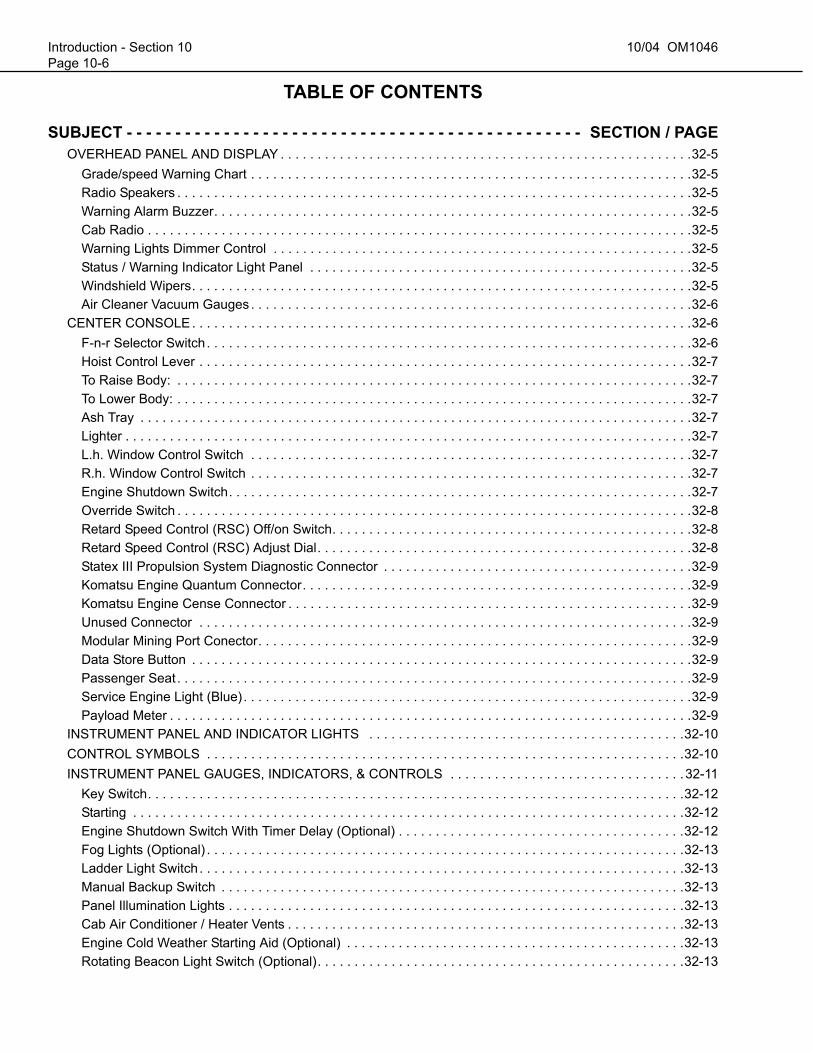
Introduction - Section 10 10/04 OM1046Page 10-6
TABLE OF CONTENTS
SUBJECT - - - - - - - - - - - - - - - - - - - - - - - - - - - - - - - - - - - - - - - - - - - - - - - SECTION / PAGEOVERHEAD PANEL AND DISPLAY . . . . . . . . . . . . . . . . . . . . . . . . . . . . . . . . . . . . . . . . . . . . . . . . . . . . . . . .32-5
Grade/speed Warning Chart . . . . . . . . . . . . . . . . . . . . . . . . . . . . . . . . . . . . . . . . . . . . . . . . . . . . . . . . . . . .32-5Radio Speakers . . . . . . . . . . . . . . . . . . . . . . . . . . . . . . . . . . . . . . . . . . . . . . . . . . . . . . . . . . . . . . . . . . . . . .32-5Warning Alarm Buzzer. . . . . . . . . . . . . . . . . . . . . . . . . . . . . . . . . . . . . . . . . . . . . . . . . . . . . . . . . . . . . . . . .32-5Cab Radio . . . . . . . . . . . . . . . . . . . . . . . . . . . . . . . . . . . . . . . . . . . . . . . . . . . . . . . . . . . . . . . . . . . . . . . . . .32-5Warning Lights Dimmer Control . . . . . . . . . . . . . . . . . . . . . . . . . . . . . . . . . . . . . . . . . . . . . . . . . . . . . . . . .32-5Status / Warning Indicator Light Panel . . . . . . . . . . . . . . . . . . . . . . . . . . . . . . . . . . . . . . . . . . . . . . . . . . . .32-5Windshield Wipers. . . . . . . . . . . . . . . . . . . . . . . . . . . . . . . . . . . . . . . . . . . . . . . . . . . . . . . . . . . . . . . . . . . .32-5Air Cleaner Vacuum Gauges . . . . . . . . . . . . . . . . . . . . . . . . . . . . . . . . . . . . . . . . . . . . . . . . . . . . . . . . . . . .32-6
CENTER CONSOLE . . . . . . . . . . . . . . . . . . . . . . . . . . . . . . . . . . . . . . . . . . . . . . . . . . . . . . . . . . . . . . . . . . . .32-6F-n-r Selector Switch. . . . . . . . . . . . . . . . . . . . . . . . . . . . . . . . . . . . . . . . . . . . . . . . . . . . . . . . . . . . . . . . . .32-6Hoist Control Lever . . . . . . . . . . . . . . . . . . . . . . . . . . . . . . . . . . . . . . . . . . . . . . . . . . . . . . . . . . . . . . . . . . .32-7To Raise Body: . . . . . . . . . . . . . . . . . . . . . . . . . . . . . . . . . . . . . . . . . . . . . . . . . . . . . . . . . . . . . . . . . . . . . .32-7To Lower Body: . . . . . . . . . . . . . . . . . . . . . . . . . . . . . . . . . . . . . . . . . . . . . . . . . . . . . . . . . . . . . . . . . . . . . .32-7Ash Tray . . . . . . . . . . . . . . . . . . . . . . . . . . . . . . . . . . . . . . . . . . . . . . . . . . . . . . . . . . . . . . . . . . . . . . . . . . .32-7Lighter . . . . . . . . . . . . . . . . . . . . . . . . . . . . . . . . . . . . . . . . . . . . . . . . . . . . . . . . . . . . . . . . . . . . . . . . . . . . .32-7L.h. Window Control Switch . . . . . . . . . . . . . . . . . . . . . . . . . . . . . . . . . . . . . . . . . . . . . . . . . . . . . . . . . . . .32-7R.h. Window Control Switch . . . . . . . . . . . . . . . . . . . . . . . . . . . . . . . . . . . . . . . . . . . . . . . . . . . . . . . . . . . .32-7Engine Shutdown Switch. . . . . . . . . . . . . . . . . . . . . . . . . . . . . . . . . . . . . . . . . . . . . . . . . . . . . . . . . . . . . . .32-7Override Switch . . . . . . . . . . . . . . . . . . . . . . . . . . . . . . . . . . . . . . . . . . . . . . . . . . . . . . . . . . . . . . . . . . . . . .32-8Retard Speed Control (RSC) Off/on Switch. . . . . . . . . . . . . . . . . . . . . . . . . . . . . . . . . . . . . . . . . . . . . . . . .32-8Retard Speed Control (RSC) Adjust Dial. . . . . . . . . . . . . . . . . . . . . . . . . . . . . . . . . . . . . . . . . . . . . . . . . . .32-8Statex III Propulsion System Diagnostic Connector . . . . . . . . . . . . . . . . . . . . . . . . . . . . . . . . . . . . . . . . . .32-9Komatsu Engine Quantum Connector. . . . . . . . . . . . . . . . . . . . . . . . . . . . . . . . . . . . . . . . . . . . . . . . . . . . .32-9Komatsu Engine Cense Connector . . . . . . . . . . . . . . . . . . . . . . . . . . . . . . . . . . . . . . . . . . . . . . . . . . . . . . .32-9Unused Connector . . . . . . . . . . . . . . . . . . . . . . . . . . . . . . . . . . . . . . . . . . . . . . . . . . . . . . . . . . . . . . . . . . .32-9Modular Mining Port Conector. . . . . . . . . . . . . . . . . . . . . . . . . . . . . . . . . . . . . . . . . . . . . . . . . . . . . . . . . . .32-9Data Store Button . . . . . . . . . . . . . . . . . . . . . . . . . . . . . . . . . . . . . . . . . . . . . . . . . . . . . . . . . . . . . . . . . . . .32-9Passenger Seat . . . . . . . . . . . . . . . . . . . . . . . . . . . . . . . . . . . . . . . . . . . . . . . . . . . . . . . . . . . . . . . . . . . . . .32-9Service Engine Light (Blue) . . . . . . . . . . . . . . . . . . . . . . . . . . . . . . . . . . . . . . . . . . . . . . . . . . . . . . . . . . . . .32-9Payload Meter . . . . . . . . . . . . . . . . . . . . . . . . . . . . . . . . . . . . . . . . . . . . . . . . . . . . . . . . . . . . . . . . . . . . . . .32-9
INSTRUMENT PANEL AND INDICATOR LIGHTS . . . . . . . . . . . . . . . . . . . . . . . . . . . . . . . . . . . . . . . . . . .32-10CONTROL SYMBOLS . . . . . . . . . . . . . . . . . . . . . . . . . . . . . . . . . . . . . . . . . . . . . . . . . . . . . . . . . . . . . . . . .32-10INSTRUMENT PANEL GAUGES, INDICATORS, & CONTROLS . . . . . . . . . . . . . . . . . . . . . . . . . . . . . . . .32-11
Key Switch. . . . . . . . . . . . . . . . . . . . . . . . . . . . . . . . . . . . . . . . . . . . . . . . . . . . . . . . . . . . . . . . . . . . . . . . .32-12Starting . . . . . . . . . . . . . . . . . . . . . . . . . . . . . . . . . . . . . . . . . . . . . . . . . . . . . . . . . . . . . . . . . . . . . . . . . . .32-12Engine Shutdown Switch With Timer Delay (Optional) . . . . . . . . . . . . . . . . . . . . . . . . . . . . . . . . . . . . . . .32-12Fog Lights (Optional) . . . . . . . . . . . . . . . . . . . . . . . . . . . . . . . . . . . . . . . . . . . . . . . . . . . . . . . . . . . . . . . . .32-13Ladder Light Switch. . . . . . . . . . . . . . . . . . . . . . . . . . . . . . . . . . . . . . . . . . . . . . . . . . . . . . . . . . . . . . . . . .32-13Manual Backup Switch . . . . . . . . . . . . . . . . . . . . . . . . . . . . . . . . . . . . . . . . . . . . . . . . . . . . . . . . . . . . . . .32-13Panel Illumination Lights . . . . . . . . . . . . . . . . . . . . . . . . . . . . . . . . . . . . . . . . . . . . . . . . . . . . . . . . . . . . . .32-13Cab Air Conditioner / Heater Vents . . . . . . . . . . . . . . . . . . . . . . . . . . . . . . . . . . . . . . . . . . . . . . . . . . . . . .32-13Engine Cold Weather Starting Aid (Optional) . . . . . . . . . . . . . . . . . . . . . . . . . . . . . . . . . . . . . . . . . . . . . .32-13Rotating Beacon Light Switch (Optional). . . . . . . . . . . . . . . . . . . . . . . . . . . . . . . . . . . . . . . . . . . . . . . . . .32-13
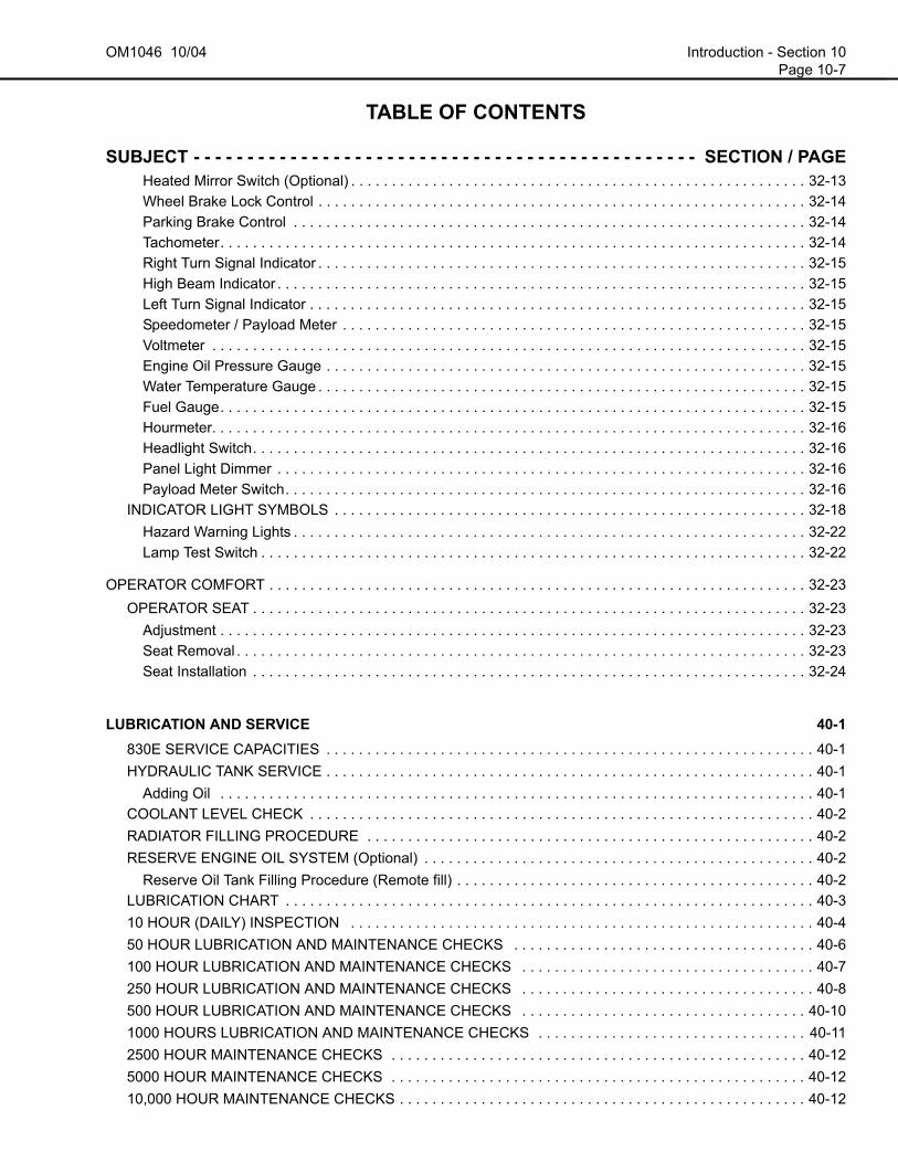
OM1046 10/04 Introduction - Section 10Page 10-7
TABLE OF CONTENTS
SUBJECT - - - - - - - - - - - - - - - - - - - - - - - - - - - - - - - - - - - - - - - - - - - - - - - SECTION / PAGEHeated Mirror Switch (Optional) . . . . . . . . . . . . . . . . . . . . . . . . . . . . . . . . . . . . . . . . . . . . . . . . . . . . . . . . 32-13Wheel Brake Lock Control . . . . . . . . . . . . . . . . . . . . . . . . . . . . . . . . . . . . . . . . . . . . . . . . . . . . . . . . . . . . 32-14Parking Brake Control . . . . . . . . . . . . . . . . . . . . . . . . . . . . . . . . . . . . . . . . . . . . . . . . . . . . . . . . . . . . . . . 32-14Tachometer. . . . . . . . . . . . . . . . . . . . . . . . . . . . . . . . . . . . . . . . . . . . . . . . . . . . . . . . . . . . . . . . . . . . . . . . 32-14Right Turn Signal Indicator . . . . . . . . . . . . . . . . . . . . . . . . . . . . . . . . . . . . . . . . . . . . . . . . . . . . . . . . . . . . 32-15High Beam Indicator . . . . . . . . . . . . . . . . . . . . . . . . . . . . . . . . . . . . . . . . . . . . . . . . . . . . . . . . . . . . . . . . . 32-15Left Turn Signal Indicator . . . . . . . . . . . . . . . . . . . . . . . . . . . . . . . . . . . . . . . . . . . . . . . . . . . . . . . . . . . . . 32-15Speedometer / Payload Meter . . . . . . . . . . . . . . . . . . . . . . . . . . . . . . . . . . . . . . . . . . . . . . . . . . . . . . . . . 32-15Voltmeter . . . . . . . . . . . . . . . . . . . . . . . . . . . . . . . . . . . . . . . . . . . . . . . . . . . . . . . . . . . . . . . . . . . . . . . . . 32-15Engine Oil Pressure Gauge . . . . . . . . . . . . . . . . . . . . . . . . . . . . . . . . . . . . . . . . . . . . . . . . . . . . . . . . . . . 32-15Water Temperature Gauge . . . . . . . . . . . . . . . . . . . . . . . . . . . . . . . . . . . . . . . . . . . . . . . . . . . . . . . . . . . . 32-15Fuel Gauge. . . . . . . . . . . . . . . . . . . . . . . . . . . . . . . . . . . . . . . . . . . . . . . . . . . . . . . . . . . . . . . . . . . . . . . . 32-15Hourmeter. . . . . . . . . . . . . . . . . . . . . . . . . . . . . . . . . . . . . . . . . . . . . . . . . . . . . . . . . . . . . . . . . . . . . . . . . 32-16Headlight Switch. . . . . . . . . . . . . . . . . . . . . . . . . . . . . . . . . . . . . . . . . . . . . . . . . . . . . . . . . . . . . . . . . . . . 32-16Panel Light Dimmer . . . . . . . . . . . . . . . . . . . . . . . . . . . . . . . . . . . . . . . . . . . . . . . . . . . . . . . . . . . . . . . . . 32-16Payload Meter Switch. . . . . . . . . . . . . . . . . . . . . . . . . . . . . . . . . . . . . . . . . . . . . . . . . . . . . . . . . . . . . . . . 32-16
INDICATOR LIGHT SYMBOLS . . . . . . . . . . . . . . . . . . . . . . . . . . . . . . . . . . . . . . . . . . . . . . . . . . . . . . . . . . 32-18Hazard Warning Lights . . . . . . . . . . . . . . . . . . . . . . . . . . . . . . . . . . . . . . . . . . . . . . . . . . . . . . . . . . . . . . . 32-22Lamp Test Switch . . . . . . . . . . . . . . . . . . . . . . . . . . . . . . . . . . . . . . . . . . . . . . . . . . . . . . . . . . . . . . . . . . . 32-22
OPERATOR COMFORT . . . . . . . . . . . . . . . . . . . . . . . . . . . . . . . . . . . . . . . . . . . . . . . . . . . . . . . . . . . . . . . . . . 32-23OPERATOR SEAT . . . . . . . . . . . . . . . . . . . . . . . . . . . . . . . . . . . . . . . . . . . . . . . . . . . . . . . . . . . . . . . . . . . . 32-23
Adjustment . . . . . . . . . . . . . . . . . . . . . . . . . . . . . . . . . . . . . . . . . . . . . . . . . . . . . . . . . . . . . . . . . . . . . . . . 32-23Seat Removal . . . . . . . . . . . . . . . . . . . . . . . . . . . . . . . . . . . . . . . . . . . . . . . . . . . . . . . . . . . . . . . . . . . . . . 32-23Seat Installation . . . . . . . . . . . . . . . . . . . . . . . . . . . . . . . . . . . . . . . . . . . . . . . . . . . . . . . . . . . . . . . . . . . . 32-24
LUBRICATION AND SERVICE 40-1830E SERVICE CAPACITIES . . . . . . . . . . . . . . . . . . . . . . . . . . . . . . . . . . . . . . . . . . . . . . . . . . . . . . . . . . . . 40-1HYDRAULIC TANK SERVICE . . . . . . . . . . . . . . . . . . . . . . . . . . . . . . . . . . . . . . . . . . . . . . . . . . . . . . . . . . . . 40-1
Adding Oil . . . . . . . . . . . . . . . . . . . . . . . . . . . . . . . . . . . . . . . . . . . . . . . . . . . . . . . . . . . . . . . . . . . . . . . . . 40-1COOLANT LEVEL CHECK . . . . . . . . . . . . . . . . . . . . . . . . . . . . . . . . . . . . . . . . . . . . . . . . . . . . . . . . . . . . . . 40-2RADIATOR FILLING PROCEDURE . . . . . . . . . . . . . . . . . . . . . . . . . . . . . . . . . . . . . . . . . . . . . . . . . . . . . . . 40-2RESERVE ENGINE OIL SYSTEM (Optional) . . . . . . . . . . . . . . . . . . . . . . . . . . . . . . . . . . . . . . . . . . . . . . . . 40-2
Reserve Oil Tank Filling Procedure (Remote fill) . . . . . . . . . . . . . . . . . . . . . . . . . . . . . . . . . . . . . . . . . . . . 40-2LUBRICATION CHART . . . . . . . . . . . . . . . . . . . . . . . . . . . . . . . . . . . . . . . . . . . . . . . . . . . . . . . . . . . . . . . . . 40-310 HOUR (DAILY) INSPECTION . . . . . . . . . . . . . . . . . . . . . . . . . . . . . . . . . . . . . . . . . . . . . . . . . . . . . . . . . 40-450 HOUR LUBRICATION AND MAINTENANCE CHECKS . . . . . . . . . . . . . . . . . . . . . . . . . . . . . . . . . . . . . 40-6100 HOUR LUBRICATION AND MAINTENANCE CHECKS . . . . . . . . . . . . . . . . . . . . . . . . . . . . . . . . . . . . 40-7250 HOUR LUBRICATION AND MAINTENANCE CHECKS . . . . . . . . . . . . . . . . . . . . . . . . . . . . . . . . . . . . 40-8500 HOUR LUBRICATION AND MAINTENANCE CHECKS . . . . . . . . . . . . . . . . . . . . . . . . . . . . . . . . . . . 40-101000 HOURS LUBRICATION AND MAINTENANCE CHECKS . . . . . . . . . . . . . . . . . . . . . . . . . . . . . . . . . 40-112500 HOUR MAINTENANCE CHECKS . . . . . . . . . . . . . . . . . . . . . . . . . . . . . . . . . . . . . . . . . . . . . . . . . . . 40-125000 HOUR MAINTENANCE CHECKS . . . . . . . . . . . . . . . . . . . . . . . . . . . . . . . . . . . . . . . . . . . . . . . . . . . 40-1210,000 HOUR MAINTENANCE CHECKS . . . . . . . . . . . . . . . . . . . . . . . . . . . . . . . . . . . . . . . . . . . . . . . . . . 40-12
Introduction - Section 10 10/04 OM1046Page 10-8
TABLE OF CONTENTS
SUBJECT - - - - - - - - - - - - - - - - - - - - - - - - - - - - - - - - - - - - - - - - - - - - - - - SECTION / PAGE
AUTOMATIC LUBRICATION SYSTEM 42-1GENERAL DESCRIPTION . . . . . . . . . . . . . . . . . . . . . . . . . . . . . . . . . . . . . . . . . . . . . . . . . . . . . . . . . . . . . . .42-1SYSTEM COMPONENTS . . . . . . . . . . . . . . . . . . . . . . . . . . . . . . . . . . . . . . . . . . . . . . . . . . . . . . . . . . . . . . .42-3System Operation . . . . . . . . . . . . . . . . . . . . . . . . . . . . . . . . . . . . . . . . . . . . . . . . . . . . . . . . . . . . . . . . . . . . . .42-4
Normal Operation: . . . . . . . . . . . . . . . . . . . . . . . . . . . . . . . . . . . . . . . . . . . . . . . . . . . . . . . . . . . . . . . . . . .42-4Pressure Failure Detection Circuits: . . . . . . . . . . . . . . . . . . . . . . . . . . . . . . . . . . . . . . . . . . . . . . . . . . . . . .42-5
INJECTOR OPERATION. . . . . . . . . . . . . . . . . . . . . . . . . . . . . . . . . . . . . . . . . . . . . . . . . . . . . . . . . . . . . . . . .42-6GENERAL INSTRUCTIONS . . . . . . . . . . . . . . . . . . . . . . . . . . . . . . . . . . . . . . . . . . . . . . . . . . . . . . . . . . . . .42-7
Lubricant Required For System . . . . . . . . . . . . . . . . . . . . . . . . . . . . . . . . . . . . . . . . . . . . . . . . . . . . . . . . .42-7System Priming . . . . . . . . . . . . . . . . . . . . . . . . . . . . . . . . . . . . . . . . . . . . . . . . . . . . . . . . . . . . . . . . . . . . .42-7Filter Assembly . . . . . . . . . . . . . . . . . . . . . . . . . . . . . . . . . . . . . . . . . . . . . . . . . . . . . . . . . . . . . . . . . . . . . .42-7
LUBRICANT PUMP . . . . . . . . . . . . . . . . . . . . . . . . . . . . . . . . . . . . . . . . . . . . . . . . . . . . . . . . . . . . . . . . . . . .42-8Pump Housing Oil Level . . . . . . . . . . . . . . . . . . . . . . . . . . . . . . . . . . . . . . . . . . . . . . . . . . . . . . . . . . . . . . .42-8Pump Pressure Control . . . . . . . . . . . . . . . . . . . . . . . . . . . . . . . . . . . . . . . . . . . . . . . . . . . . . . . . . . . . . . .42-8Pressure Control Valve Adjustment . . . . . . . . . . . . . . . . . . . . . . . . . . . . . . . . . . . . . . . . . . . . . . . . . . . . . .42-8
INJECTORS (SL-1 Series “H”)) . . . . . . . . . . . . . . . . . . . . . . . . . . . . . . . . . . . . . . . . . . . . . . . . . . . . . . . . . . .42-9Injector Specifications . . . . . . . . . . . . . . . . . . . . . . . . . . . . . . . . . . . . . . . . . . . . . . . . . . . . . . . . . . . . . . . . .42-9Injector Adjustment . . . . . . . . . . . . . . . . . . . . . . . . . . . . . . . . . . . . . . . . . . . . . . . . . . . . . . . . . . . . . . . . . . .42-9
SYSTEM CHECKOUT . . . . . . . . . . . . . . . . . . . . . . . . . . . . . . . . . . . . . . . . . . . . . . . . . . . . . . . . . . . . . . . . .42-10Lubrication Cycle Timer Check . . . . . . . . . . . . . . . . . . . . . . . . . . . . . . . . . . . . . . . . . . . . . . . . . . . . . . . . .42-10Lubrication Cycle Timer Adjustment . . . . . . . . . . . . . . . . . . . . . . . . . . . . . . . . . . . . . . . . . . . . . . . . . . . . .42-10
SYSTEM TROUBLESHOOTING CHART . . . . . . . . . . . . . . . . . . . . . . . . . . . . . . . . . . . . . . . . . . . . . . . . . . . . .42-11
PREVENTATIVE MAINTENANCE PROCEDURES . . . . . . . . . . . . . . . . . . . . . . . . . . . . . . . . . . . . . . . . . . . . .42-13Daily Lubrication System Inspection . . . . . . . . . . . . . . . . . . . . . . . . . . . . . . . . . . . . . . . . . . . . . . . . . . . .42-13250 Hour Inspection . . . . . . . . . . . . . . . . . . . . . . . . . . . . . . . . . . . . . . . . . . . . . . . . . . . . . . . . . . . . . . . . .42-131000 Hour Inspection . . . . . . . . . . . . . . . . . . . . . . . . . . . . . . . . . . . . . . . . . . . . . . . . . . . . . . . . . . . . . . . .42-13
MAJOR COMPONENT DESCRIPTION 50-1
PAYLOAD METER III 60-1
OM1046 10/04 Introduction - Section 10Page 10-9
TABLE OF CONTENTSSUBJECT SECTION / PAGE
RADIO, AM / FM STEREO CASSETTE 70-1SETTING THE TIME . . . . . . . . . . . . . . . . . . . . . . . . . . . . . . . . . . . . . . . . . . . . . . . . . . . . . . . . . . . . . . . . . . . 70-1GENERAL RECEIVER FUNCTIONS . . . . . . . . . . . . . . . . . . . . . . . . . . . . . . . . . . . . . . . . . . . . . . . . . . . . . . 70-1
Turning The Power On And Off . . . . . . . . . . . . . . . . . . . . . . . . . . . . . . . . . . . . . . . . . . . . . . . . . . . . . . . . . 70-1Display . . . . . . . . . . . . . . . . . . . . . . . . . . . . . . . . . . . . . . . . . . . . . . . . . . . . . . . . . . . . . . . . . . . . . . . . . . . . 70-1Setting The Default Display . . . . . . . . . . . . . . . . . . . . . . . . . . . . . . . . . . . . . . . . . . . . . . . . . . . . . . . . . . . . 70-2Adjusting Display Brightness . . . . . . . . . . . . . . . . . . . . . . . . . . . . . . . . . . . . . . . . . . . . . . . . . . . . . . . . . . . 70-2
OPERATING THE RADIO . . . . . . . . . . . . . . . . . . . . . . . . . . . . . . . . . . . . . . . . . . . . . . . . . . . . . . . . . . . . . . . 70-2BAND . . . . . . . . . . . . . . . . . . . . . . . . . . . . . . . . . . . . . . . . . . . . . . . . . . . . . . . . . . . . . . . . . . . . . . . . . . . . . 70-2TUNE/SEEK . . . . . . . . . . . . . . . . . . . . . . . . . . . . . . . . . . . . . . . . . . . . . . . . . . . . . . . . . . . . . . . . . . . . . . . 70-2Manual Tuning . . . . . . . . . . . . . . . . . . . . . . . . . . . . . . . . . . . . . . . . . . . . . . . . . . . . . . . . . . . . . . . . . . . . . . 70-2SEEK Mode . . . . . . . . . . . . . . . . . . . . . . . . . . . . . . . . . . . . . . . . . . . . . . . . . . . . . . . . . . . . . . . . . . . . . . . . 70-2SCAN . . . . . . . . . . . . . . . . . . . . . . . . . . . . . . . . . . . . . . . . . . . . . . . . . . . . . . . . . . . . . . . . . . . . . . . . . . . . . 70-2AUTO . . . . . . . . . . . . . . . . . . . . . . . . . . . . . . . . . . . . . . . . . . . . . . . . . . . . . . . . . . . . . . . . . . . . . . . . . . . . . 70-2
ADJUSTING THE RECEIVER SETTINGS . . . . . . . . . . . . . . . . . . . . . . . . . . . . . . . . . . . . . . . . . . . . . . . . . . 70-3PROGRAMMING PRESET STATIONS . . . . . . . . . . . . . . . . . . . . . . . . . . . . . . . . . . . . . . . . . . . . . . . . . . . . . 70-3OPERATION OF THE WEATHERBAND (U.S.) . . . . . . . . . . . . . . . . . . . . . . . . . . . . . . . . . . . . . . . . . . . . . . 70-3SATELLITE RADIO . . . . . . . . . . . . . . . . . . . . . . . . . . . . . . . . . . . . . . . . . . . . . . . . . . . . . . . . . . . . . . . . . . . . 70-4
Operating Satellite Radio . . . . . . . . . . . . . . . . . . . . . . . . . . . . . . . . . . . . . . . . . . . . . . . . . . . . . . . . . . . . . . 70-4Program Type Search (PTY) . . . . . . . . . . . . . . . . . . . . . . . . . . . . . . . . . . . . . . . . . . . . . . . . . . . . . . . . . . . 70-4
CASSETTE PLAYER . . . . . . . . . . . . . . . . . . . . . . . . . . . . . . . . . . . . . . . . . . . . . . . . . . . . . . . . . . . . . . . . . . 70-5Playing A Cassette . . . . . . . . . . . . . . . . . . . . . . . . . . . . . . . . . . . . . . . . . . . . . . . . . . . . . . . . . . . . . . . . . . 70-5Cassette Functions . . . . . . . . . . . . . . . . . . . . . . . . . . . . . . . . . . . . . . . . . . . . . . . . . . . . . . . . . . . . . . . . . . 70-5
PROGRAMMABLE EJECT DEFAULT . . . . . . . . . . . . . . . . . . . . . . . . . . . . . . . . . . . . . . . . . . . . . . . . . . . . . 70-5Bad Tape Detect . . . . . . . . . . . . . . . . . . . . . . . . . . . . . . . . . . . . . . . . . . . . . . . . . . . . . . . . . . . . . . . . . . . . 70-5
CASSETTE PLAYER CLEANING . . . . . . . . . . . . . . . . . . . . . . . . . . . . . . . . . . . . . . . . . . . . . . . . . . . . . . . . . 70-5
Introduction - Section 10 10/04 OM1046Page 10-10
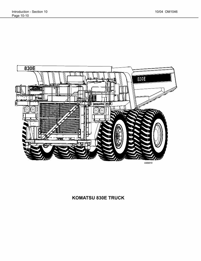
KOMATSU 830E TRUCK
OM1046 10/04 Introduction - Section 10Page 10-11
ABOUT THIS MANUALThis Manual is written for use by the operator and/or the service technician and is designed to help these personsto become fully knowledgeable of the truck and all its systems in order to keep it operating safely and efficiently. Alloperators and maintenance personnel should read and understand the materials in this manual before operatingthe truck or performing maintenance and/or operational checks on the truck. All safety notices, warnings, and cau-tions should be understood and followed when operating or accomplishing repairs on the truck.
The front cover of this manual includes a Form Number. This Form No. should be referenced when ordering addi-tional copies of this manual, or for any other correspondence regarding the coverage in this manual.
Direct all inquiries to:
Komatsu America Corp.DataKom, Peoria Technical PublicationsP.O. Box 240Peoria, IL 61650-0240FAX - (309)-672-7072
This first section is an Introduction to the manual and contains a Table of Contents to locate specific areas of inter-est. Other sections include Safety, Operation, Maintenance, Specifications, and Optional Equipment.
When searching for a specific area of interest, go first to the Table of Contents to locate the Section in which thesubject might generally be included. Then, go to that Section of the Table of Contents to find a Subject descriptionthat most closely describes the specific area of interest to find a page number and go to that page. Section Num-bers and Page Numbers are located at the top, outside corner of the page.
At the top, inside corner of the page is a document (module) number. If there is ever a question regarding the infor-mation in a particular Section, refer to the document (module) number, the manual Form No., and use the addressshown above to correspond. If there is a date (month/year) behind the document (module) number, that indicatesthe latest revision date of that page.
The illustrations used in this manual are TYPICAL of the component shown and may not be an exact reproductionof what is found on the truck.
This manual shows dimensioning of U.S. standard and metric (SI) units throughout. All references to Right, Left,Front, or Rear are made with respect to the operator’s normal seated position, unless specifically stated otherwise.
When assembly instructions are provided without references to torque values, standard torque values should beassumed. Standard torque requirements are shown in torque charts on the following pages of this section, and inthe General Information section of the truck service manual. Individual torques when provided in the text are in boldface type, such as 100 ft. lbs. (135 N.m) torque. All torque specifications have ±10% tolerance unless otherwisespecified.

Introduction - Section 10 10/04 OM1046Page 10-12
NOTES:
OM1200 Standard Charts and Tables - Section 12Page 12-1
STANDARD CHARTS AND TABLESThis manual provides dual dimensioning for most spec-ifications. U.S. standard units are specified first, withmetric (SI) units in parentheses. References through-out the manual to standard torques or other standardvalues will be to one of the following Charts or Tables.For values not shown in any of the charts or tables,standard conversion factors for most commonly usedmeasurements are provided in TABLE XIII, page 12-6.
INDEX OF TABLESTABLE I . . . . . . . Standard Torque Chart (SAE) . . 12-9TABLE II . Standard Torque, 12-Point, Grade 9 . 12-10TABLE III . . Standard Metric Assembly Torque . 12-10TABLE IV . . . . . . JIC Swivel Nuts Torque Chart . 12-11TABLE V . . . . . . . . .Pipe Thread Torque Chart . 12-11TABLE VI . . . . . . . . O-Ring Boss Torque Chart . 12-11TABLEVII . . . . O-Ring Face Seal Torque Chart . 12-11TABLE VIII . Torque Conversions (ft.lbs. - N.m) . 12-12TABLE IX . . Torque Conversions (ft.lbs. - kg.m) . 12-12TABLE X . . . Pressure Conversions (psi - kPa) . 12-12TABLE XI . . Pressure Conversions (psi - MPa) . 12-12TABLE XII . . . . . . . .Temperature Conversions . 12-13TABLE XIII . . .Common Conversion Multipliers . 12-14
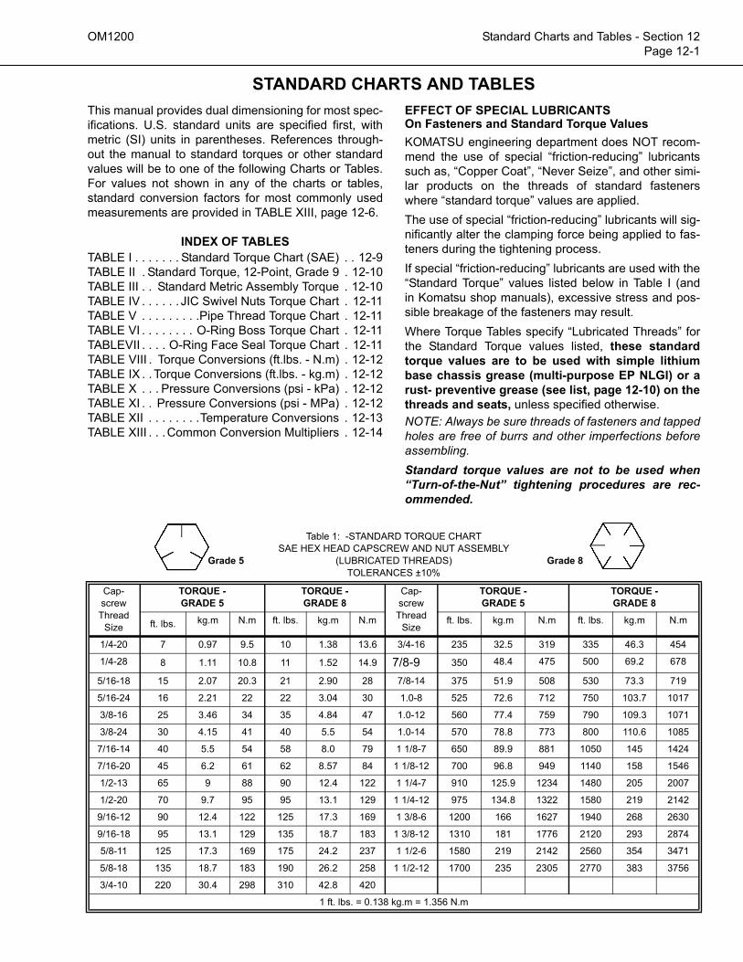
EFFECT OF SPECIAL LUBRICANTSOn Fasteners and Standard Torque ValuesKOMATSU engineering department does NOT recom-mend the use of special “friction-reducing” lubricantssuch as, “Copper Coat”, “Never Seize”, and other simi-lar products on the threads of standard fastenerswhere “standard torque” values are applied. The use of special “friction-reducing” lubricants will sig-nificantly alter the clamping force being applied to fas-teners during the tightening process. If special “friction-reducing” lubricants are used with the“Standard Torque” values listed below in Table I (andin Komatsu shop manuals), excessive stress and pos-sible breakage of the fasteners may result. Where Torque Tables specify “Lubricated Threads” forthe Standard Torque values listed, these standardtorque values are to be used with simple lithiumbase chassis grease (multi-purpose EP NLGI) or arust- preventive grease (see list, page 12-10) on thethreads and seats, unless specified otherwise.NOTE: Always be sure threads of fasteners and tappedholes are free of burrs and other imperfections beforeassembling.Standard torque values are not to be used when“Turn-of-the-Nut” tightening procedures are rec-ommended.
Table 1: -STANDARD TORQUE CHARTSAE HEX HEAD CAPSCREW AND NUT ASSEMBLY
(LUBRICATED THREADS)TOLERANCES ±10%
Cap-screw
Thread Size
TORQUE - GRADE 5
TORQUE - GRADE 8
Cap-screw
Thread Size
TORQUE - GRADE 5
TORQUE - GRADE 8
ft. lbs. kg.m N.m ft. lbs. kg.m N.m ft. lbs. kg.m N.m ft. lbs. kg.m N.m
1/4-20 7 0.97 9.5 10 1.38 13.6 3/4-16 235 32.5 319 335 46.3 454
1/4-28 8 1.11 10.8 11 1.52 14.9 7/8-9 350 48.4 475 500 69.2 678
5/16-18 15 2.07 20.3 21 2.90 28 7/8-14 375 51.9 508 530 73.3 719
5/16-24 16 2.21 22 22 3.04 30 1.0-8 525 72.6 712 750 103.7 1017
3/8-16 25 3.46 34 35 4.84 47 1.0-12 560 77.4 759 790 109.3 1071
3/8-24 30 4.15 41 40 5.5 54 1.0-14 570 78.8 773 800 110.6 1085
7/16-14 40 5.5 54 58 8.0 79 1 1/8-7 650 89.9 881 1050 145 1424
7/16-20 45 6.2 61 62 8.57 84 1 1/8-12 700 96.8 949 1140 158 1546
1/2-13 65 9 88 90 12.4 122 1 1/4-7 910 125.9 1234 1480 205 2007
1/2-20 70 9.7 95 95 13.1 129 1 1/4-12 975 134.8 1322 1580 219 2142
9/16-12 90 12.4 122 125 17.3 169 1 3/8-6 1200 166 1627 1940 268 2630
9/16-18 95 13.1 129 135 18.7 183 1 3/8-12 1310 181 1776 2120 293 2874
5/8-11 125 17.3 169 175 24.2 237 1 1/2-6 1580 219 2142 2560 354 3471
5/8-18 135 18.7 183 190 26.2 258 1 1/2-12 1700 235 2305 2770 383 3756
3/4-10 220 30.4 298 310 42.8 420
1 ft. lbs. = 0.138 kg.m = 1.356 N.m
Grade 5 Grade 8
Standard Charts and Tables - Section 12 OM1200Page 12-2
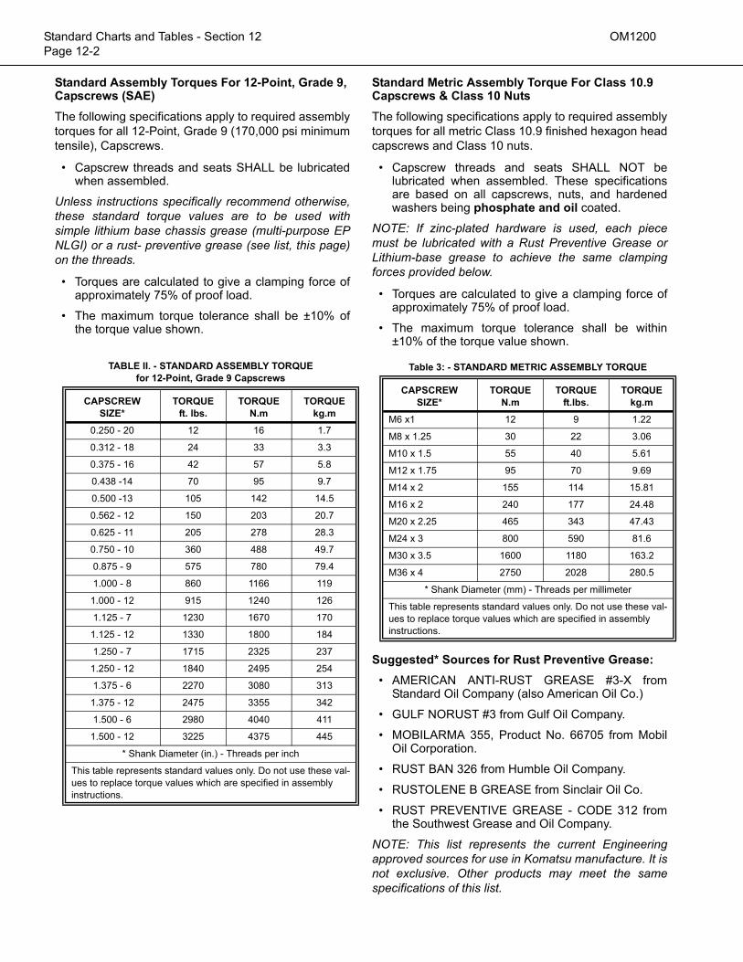
Standard Assembly Torques For 12-Point, Grade 9, Capscrews (SAE)The following specifications apply to required assemblytorques for all 12-Point, Grade 9 (170,000 psi minimumtensile), Capscrews.
• Capscrew threads and seats SHALL be lubricatedwhen assembled.
Unless instructions specifically recommend otherwise,these standard torque values are to be used withsimple lithium base chassis grease (multi-purpose EPNLGI) or a rust- preventive grease (see list, this page)on the threads.
• Torques are calculated to give a clamping force ofapproximately 75% of proof load.
• The maximum torque tolerance shall be ±10% ofthe torque value shown.
Standard Metric Assembly Torque For Class 10.9 Capscrews & Class 10 NutsThe following specifications apply to required assemblytorques for all metric Class 10.9 finished hexagon headcapscrews and Class 10 nuts.
• Capscrew threads and seats SHALL NOT belubricated when assembled. These specificationsare based on all capscrews, nuts, and hardenedwashers being phosphate and oil coated.
NOTE: If zinc-plated hardware is used, each piecemust be lubricated with a Rust Preventive Grease orLithium-base grease to achieve the same clampingforces provided below.
• Torques are calculated to give a clamping force ofapproximately 75% of proof load.
• The maximum torque tolerance shall be within±10% of the torque value shown.
Suggested* Sources for Rust Preventive Grease: • AMERICAN ANTI-RUST GREASE #3-X from
Standard Oil Company (also American Oil Co.)
• GULF NORUST #3 from Gulf Oil Company.
• MOBILARMA 355, Product No. 66705 from MobilOil Corporation.
• RUST BAN 326 from Humble Oil Company.
• RUSTOLENE B GREASE from Sinclair Oil Co.
• RUST PREVENTIVE GREASE - CODE 312 fromthe Southwest Grease and Oil Company.
NOTE: This list represents the current Engineeringapproved sources for use in Komatsu manufacture. It isnot exclusive. Other products may meet the samespecifications of this list.
TABLE II. - STANDARD ASSEMBLY TORQUEfor 12-Point, Grade 9 Capscrews
CAPSCREW SIZE*
TORQUEft. lbs.
TORQUEN.m
TORQUEkg.m
0.250 - 20 12 16 1.7
0.312 - 18 24 33 3.3
0.375 - 16 42 57 5.8
0.438 -14 70 95 9.7
0.500 -13 105 142 14.5
0.562 - 12 150 203 20.7
0.625 - 11 205 278 28.3
0.750 - 10 360 488 49.7
0.875 - 9 575 780 79.4
1.000 - 8 860 1166 119
1.000 - 12 915 1240 126
1.125 - 7 1230 1670 170
1.125 - 12 1330 1800 184
1.250 - 7 1715 2325 237
1.250 - 12 1840 2495 254
1.375 - 6 2270 3080 313
1.375 - 12 2475 3355 342
1.500 - 6 2980 4040 411
1.500 - 12 3225 4375 445
* Shank Diameter (in.) - Threads per inch
This table represents standard values only. Do not use these val-ues to replace torque values which are specified in assembly instructions.
Table 3: - STANDARD METRIC ASSEMBLY TORQUE
CAPSCREW SIZE*
TORQUEN.m
TORQUEft.lbs.
TORQUEkg.m
M6 x1 12 9 1.22
M8 x 1.25 30 22 3.06
M10 x 1.5 55 40 5.61
M12 x 1.75 95 70 9.69
M14 x 2 155 114 15.81
M16 x 2 240 177 24.48
M20 x 2.25 465 343 47.43
M24 x 3 800 590 81.6
M30 x 3.5 1600 1180 163.2
M36 x 4 2750 2028 280.5
* Shank Diameter (mm) - Threads per millimeter
This table represents standard values only. Do not use these val-ues to replace torque values which are specified in assembly instructions.
OM1200 Standard Charts and Tables - Section 12Page 12-3
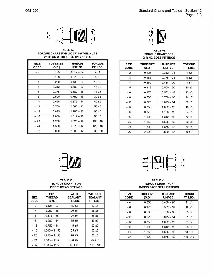
TABLE IV. TORQUE CHART FOR JIC 37° SWIVEL NUTS
WITH OR WITHOUT O-RING SEALS
SIZECODE
TUBE SIZE (O.D.)
THREADS UNF-2B
TORQUE FT. LBS.
– 2 0.125 0.312 – 24 4 ±1
– 3 0.188 0.375 – 24 8 ±3
– 4 0.250 0.438 – 20 12 ±3
– 5 0.312 0.500 – 20 15 ±3
– 6 0.375 0.562 – 18 18 ±5
– 8 0.500 0.750 – 16 30 ±5
– 10 0.625 0.875 – 14 40 ±5
– 12 0.750 1.062 – 12 55 ±5
– 14 0.875 1.188 – 12 65 ±5
– 16 1.000 1.312 – 12 80 ±5
– 20 1.250 1.625 – 12 100 ±10
– 24 1.500 1.875 – 12 120 ±10
– 32 2.000 2.500 – 12 230 ±20
TABLE VI. TORQUE CHART FOR
O-RING BOSS FITTINGS
SIZECODE
TUBE SIZE (O.D.)
THREADS UNF-2B
TORQUE FT. LBS.
– 2 0.125 0.312 – 24 4 ±2
– 3 0.188 0.375 – 24 5 ±2
– 4 0.250 0.438 – 20 8 ±3
– 5 0.312 0.500 – 20 10 ±3
– 6 0.375 0.562 – 18 13 ±3
– 8 0.500 0.750 – 16 24 ±5
– 10 0.625 0.875 – 14 32 ±5
– 12 0.750 1.062 – 12 48 ±5
– 14 0.875 1.188 – 12 54 ±5
– 16 1.000 1.312 – 12 72 ±5
– 20 1.250 1.625 – 12 80 ±5
– 24 1.500 1.875 – 12 80 ±5
– 32 2.000 2.500 – 12 96 ±10
TABLE V. TORQUE CHART FOR
PIPE THREAD FITTINGS
SIZECODE
PIPE THREAD
SIZE
WITH SEALANTFT. LBS.
WITHOUTSEALANT FT. LBS.
– 2 0.125 – 27 15 ±3 20 ±5
– 4 0.250 – 18 20 ±5 25 ±5
– 6 0.375 – 18 25 ±5 35 ±5
– 8 0.500 – 14 35 ±5 45 ±5
– 12 0.750 – 14 45 ±5 55 ±5
– 16 1.000 – 11.50 55 ±5 65 ±5
– 20 1.250 – 11.50 70 ±5 80 ±5
– 24 1.500 – 11.50 80 ±5 95 ±10
– 32 2.000 – 11.50 95 ±10 120 ±10
TABLE VII. TORQUE CHART FOR
O-RING FACE SEAL FITTINGS
SIZECODE
TUBE SIZE (O.D.)
THREADS UNF-2B
TORQUE FT. LBS.
– 4 0.250 0.438 – 20 11 ±1
– 6 0.375 0.562 – 18 18 ±2
– 8 0.500 0.750 – 16 35 ±4
– 10 0.625 0.875 – 14 51 ±5
– 12 0.750 1.062 – 12 71 ±7
– 16 1.000 1.312 – 12 98 ±6
– 20 1.250 1.625 – 12 132 ±7
– 24 1.500 1.875 – 12 165 ±15

Standard Charts and Tables - Section 12 OM1200Page 12-4
TABLE X. PRESSURE CONVERSIONSPounds/square inch (psi) To Kilopascals (kPa)
Formula: psi x 6.895 = kPa
PSI 0 1 2 3 4 5 6 7 8 90 (kPa) 6.895 13.79 20.68 27.58 34.47 41.37 48.26 55.16 62.05
10 68.95 75.84 82.74 89.63 96.53 103.42 110.32 117.21 124.1 131.0
20 137.9 144.8 151.7 158.6 165.5 172.4 179.3 186.2 193.1 200.0
30 206.8 213.7 220.6 227.5 234.4 241.3 248.2 255.1 262.0 268.9
40 275.8 282.7 289.6 296.5 303.4 310.3 317.2 324.1 331.0 337.9
50 344.7 351.6 358.5 365.4 372.3 379.2 386.1 393.0 399.9 406.8
60 413.7 420.6 427.5 434.4 441.3 448.2 455.1 462.0 468.9 475.8
70 482.6 489.5 496.4 503.3 510.2 517.1 524.0 530.9 537.8 544.7
80 551.6 558.5 565.4 572.3 579.2 586.1 593.0 599.9 606.8 613.7
90 620.5 627.4 634.3 641.2 648.1 655.0 661.9 668.8 675.7 682.6
See NOTE on page 12-5 regarding table usage
TABLE VIII. TORQUE CONVERSIONSFoot Pounds – ft. lbs. To Newton-meters (N.m)
FT. LBS. 0 1 2 3 4 5 6 7 8 9
0 (N.m) 1.36 2.71 4.07 5.42 6.78 8.14 9.49 10.85 12.20
10 13.56 14.91 16.27 17.63 18.98 20.34 21.69 23.05 24.40 25.76
20 27.12 28.47 29.83 31.18 32.54 33.90 35.25 36.61 37.96 39.32
30 40.67 42.03 43.39 44.74 46.10 47.45 48.81 50.17 51.52 52.87
40 54.23 55.59 56.94 58.30 59.66 60.01 62.37 63.72 65.08 66.44
50 67.79 69.15 70.50 71.86 73.21 74.57 75.93 77.28 78.64 80.00
60 81.35 82.70 84.06 85.42 86.77 88.13 89.48 90.84 92.20 93.55
70 94.91 96.26 97.62 98.97 100.33 101.69 103.04 104.40 105.75 107.11
80 108.47 109.82 111.18 112.53 113.89 115.24 116.60 117.96 119.31 120.67
90 122.03 123.38 124.74 126.09 127.45 128.80 130.16 131.51 132.87 134.23
See NOTE on page 12-5 regarding table usage
TABLE IX. TORQUE CONVERSIONSFoot Pounds – ft. lbs. To kilogram-meters (kg.m)
FT. LBS. 0 1 2 3 4 5 6 7 8 9
0 (kg.m) 0.138 0.277 0.415 0.553 0.692 0.830 0.968 1.106 1.245
10 1.38 1.52 1.66 1.80 1.94 2.07 2.21 2.35 2.49 2.63
20 2.77 2.90 3.04 3.18 3.32 3.46 3.60 3.73 3.87 4.01
30 4.15 4.29 4.43 4.56 4.70 4.84 4.98 5.12 5.26 5.39
40 5.53 5.67 5.81 5.95 6.09 6.22 6.36 6.50 6.64 6.78
50 6.92 7.05 7.19 7.33 7.47 7.61 7.74 7.88 8.02 8.16
60 8.30 8.44 8.57 8.71 8.85 8.99 9.13 9.27 9.40 9.54
70 9.68 9.82 9.96 10.10 10.23 10.37 10.51 10.65 10.79 10.93
80 11.06 11.20 11.34 11.48 11.62 11.76 11.89 12.03 12.17 12.30
90 12.45 12.59 12.72 12.86 13.00 13.14 13.28 13.42 13.55 13.69
See NOTE on page 12-5 regarding table usage
OM1200 Standard Charts and Tables - Section 12Page 12-5
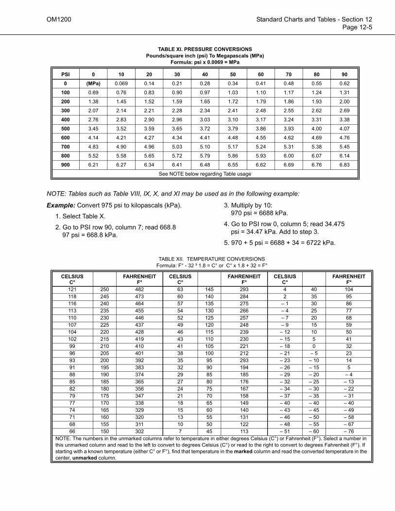
TABLE XII. TEMPERATURE CONVERSIONSFormula: F° - 32 ³ 1.8 = C° or C° x 1.8 + 32 = F°
CELSIUSC°
FAHRENHEITF°
CELSIUSC°
FAHRENHEITF°
CELSIUSC°
FAHRENHEITF°
121 250 482 63 145 293 4 40 104118 245 473 60 140 284 2 35 95116 240 464 57 135 275 – 1 30 86113 235 455 54 130 266 – 4 25 77110 230 446 52 125 257 – 7 20 68107 225 437 49 120 248 – 9 15 59104 220 428 46 115 239 – 12 10 50102 215 419 43 110 230 – 15 5 4199 210 410 41 105 221 – 18 0 3296 205 401 38 100 212 – 21 – 5 2393 200 392 35 95 293 – 23 – 10 1491 195 383 32 90 194 – 26 – 15 588 190 374 29 85 185 – 29 – 20 – 485 185 365 27 80 176 – 32 – 25 – 1382 180 356 24 75 167 – 34 – 30 – 2279 175 347 21 70 158 – 37 – 35 – 3177 170 338 18 65 149 – 40 – 40 – 4074 165 329 15 60 140 – 43 – 45 – 4971 160 320 13 55 131 – 46 – 50 – 5868 155 311 10 50 122 – 48 – 55 – 6766 150 302 7 45 113 – 51 – 60 – 76
NOTE: The numbers in the unmarked columns refer to temperature in either degrees Celsius (C°) or Fahrenheit (F°). Select a number in this unmarked column and read to the left to convert to degrees Celsius (C°) or read to the right to convert to degrees Fahrenheit (F°). If starting with a known temperature (either C° or F°), find that temperature in the marked column and read the converted temperature in the center, unmarked column.
TABLE XI. PRESSURE CONVERSIONSPounds/square inch (psi) To Megapascals (MPa)
Formula: psi x 0.0069 = MPa
PSI 0 10 20 30 40 50 60 70 80 900 (MPa) 0.069 0.14 0.21 0.28 0.34 0.41 0.48 0.55 0.62
100 0.69 0.76 0.83 0.90 0.97 1.03 1.10 1.17 1.24 1.31
200 1.38 1.45 1.52 1.59 1.65 1.72 1.79 1.86 1.93 2.00
300 2.07 2.14 2.21 2.28 2.34 2.41 2.48 2.55 2.62 2.69
400 2.76 2.83 2.90 2.96 3.03 3.10 3.17 3.24 3.31 3.38
500 3.45 3.52 3.59 3.65 3.72 3.79 3.86 3.93 4.00 4.07
600 4.14 4.21 4.27 4.34 4.41 4.48 4.55 4.62 4.69 4.76
700 4.83 4.90 4.96 5.03 5.10 5.17 5.24 5.31 5.38 5.45
800 5.52 5.58 5.65 5.72 5.79 5.86 5.93 6.00 6.07 6.14
900 6.21 6.27 6.34 6.41 6.48 6.55 6.62 6.69 6.76 6.83
See NOTE below regarding Table usage
NOTE: Tables such as Table VIII, IX, X, and XI may be used as in the following example:
Example: Convert 975 psi to kilopascals (kPa).
1. Select Table X.
2. Go to PSI row 90, column 7; read 668.897 psi = 668.8 kPa.
3. Multiply by 10:970 psi = 6688 kPa.
4. Go to PSI row 0, column 5; read 34.475 psi = 34.47 kPa. Add to step 3.
5. 970 + 5 psi = 6688 + 34 = 6722 kPa.

Standard Charts and Tables - Section 12 OM1200Page 12-6
TABLE XIIICOMMON CONVERSION MULTIPLIERS
COMMON CONVERSION MULTIPLIERSENGLISH To METRIC
To ConvertFrom TO
MultiplyBy
inch – in. millimeter (mm) 25.40
inch – in. centimeter (cm) 2.54
foot – ft. meter (m) 0.3048
yard – yd. meter (m) 0.914
mile – mi. kilometer (km) 1.61
sq. in. – in.2 sq. centimeters (cm2) 6.45
sq. ft. – ft.2 sq. centimeters (cm2) 929
cu. in. – in.3 cu. centimeters (cm3) 16.39
cu. in. – in.3 liters (l) 0.016
cu. ft. – ft.3 cu. meters (m3) 0.028
cu. ft. – ft.3 liters (l) 28.3
ounce – oz. kilogram (kg) 0.028
fluid ounce – fl. oz. milliliter (ml) 29.573
pound (mass) kilogram (kg) 0.454
pound (force) – lbs. Newton (N) 4.448
in. lbs. (force) Newton.meters (N.m) 0.113
ft. lbs. (force) Newton.meters (N.m) 1.356
ft. lbs. (force) kilogram.meters (kg.m) 0.138
kilogram.meters (kg.m)
Newton.meters (N.m) 9.807
psi (pressure) kilopascals (kPa) 6.895
psi (pressure) megapascals (MPa) 0.007
psi (pressure) kilograms/cm2 (kg/cm2) 0.0704
ton (short) kilogram (kg) 907.2
ton (short) metric ton 0.0907
quart – qt. liters (l) 0.946
gallon – gal. liters (l) 3.785
HP (horsepower) Watts 745.7
HP (horsepower) kilowatts (kw) 0.745
COMMON CONVERSION MULTIPLIERSMETRIC To ENGLISH
To Convert From TOMultiply
Bymillimeter (mm) inch – in. 0.0394
centimeter (cm) inch – in. 0.3937
meter (m) foot – ft. 3.2808
meter (m) yard – yd. 1.0936
kilometer (km) mile – mi. 0.6210
sq. centimeters (cm2) sq. in. – in.2 0.1550
sq. centimeters (cm2) sq. ft. – ft.2 0.001
cu. centimeters (cm3) cu. in. – in.3 0.061
liters (l) cu. in. – in.3 61.02
cu. meters (m3) cu. ft. – ft.3 35.314
liters (l) cu. ft. – ft.3 0.0353
grams (g) ounce – oz. 0.0353
milliliter (ml) fluid ounce – fl. oz. 0.0338
kilogram (kg) pound (mass) 2.2046
Newton (N) pound (force) – lbs. 0.2248
Newton.meters (N.m) kilogram.meters (kg.m) 0.102
Newton.meters (N.m) ft. lbs. (force) 0.7376
kilogram.meters (kg.m) ft. lbs. (force) 7.2329
kilogram.meters (kg.m) Newton.meters (N.m) 9.807
Kilopascals (kPa) psi (pressure) 0.1450
megapascals (MPa) psi (pressure) 145.038
kilograms/cm2 (kg/cm2) psi (pressure) 14.2231
kilograms/cm2 (kg/cm2) kilopascals (kPa) 98.068
kilogram (kg) ton (short) 0.0011
metric ton ton (short) 1.1023
liters (l) quart – qt. 1.0567
liters (l) gallon – gal. 0.2642
Watts HP (horsepower) 0.00134
kilowatts (kw) HP (horsepower) 1.3410
OM2034 10/04 General Safety - Section 20Page 20-1
GENERAL SAFETYSafety records of most organizations will show that the greatest percentage of accidents are caused by unsafe actsof persons. The remainder are caused by unsafe mechanical or physical conditions. Report all unsafe conditions tothe proper authority.
The following safety rules are provided as a guide for the operator. However, local conditions and regulations mayadd many more to this list.
Safety Rules
• ONLY trained and authorized personnel can operate and maintain the machine.
• Follow all safety rules, precautions and instructions when operating or performing maintenance on themachine.
• When working with another operator or a person on work site traffic duty, be sure all personnel understand allhand signals that are to be used.
Safety Features
• Be sure all guards and covers are in their proper position. Have guards and covers repaired if damaged. (SeeWalk-Around Inspection, Operating Instructions - Section 30)
• Learn the proper use of safety features such as safety locks, safety pins, and seat belts, and use these safetyfeatures properly.
• NEVER remove any safety features. ALWAYS keep them in good operating condition.
• Improper use of safety features could result in serious bodily injury or death.
Clothing And Personal Items
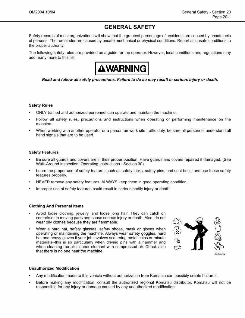
• Avoid loose clothing, jewelry, and loose long hair. They can catch oncontrols or in moving parts and cause serious injury or death. Also, do notwear oily clothes because they are flammable.
• Wear a hard hat, safety glasses, safety shoes, mask or gloves whenoperating or maintaining the machine. Always wear safety goggles, hardhat and heavy gloves if your job involves scattering metal chips or minutematerials--this is so particularly when driving pins with a hammer andwhen cleaning the air cleaner element with compressed air. Check alsothat there is no one near the machine.
Unauthorized Modification
• Any modification made to this vehicle without authorization from Komatsu can possibly create hazards.
• Before making any modification, consult the authorized regional Komatsu distributor. Komatsu will not beresponsible for any injury or damage caused by any unauthorized modification.
Read and follow all safety precautions. Failure to do so may result in serious injury or death.
General Safety - Section 20 10/04 OM2034Page 20-2
Leaving The Operator's Seat
• When preparing to leave the operator's seat, do not touch any control lever that is not locked. To preventaccidental operations from occurring, always carry out the following:
• Move the shift control lever to Neutral (N) and set the parking lever/switch to the PARKING position.
• Lower the dump body, set the dump lever to the FLOAT position.
• Stop the engine. When leaving the machine, always lock everything. Always remember to take the key withyou. If the machine should suddenly move or move in an unexpected way, this may result in serious bodilyinjury or death.
Mounting And Dismounting
• NEVER jump on or off the machine. NEVER get on or off a moving machine.
• When getting on or off the machine, face the machine and use the hand-hold and steps.
• Never hold any control levers when getting on or off the machine.
• Always maintain three-point contact with the hand-holds and steps to ensure that you support yourself.
• When bringing tools to the operator's compartment, always pass them by hand or pull them up by rope.
• If there is any oil, grease, or mud on the hand-holds or steps, wipe it off immediately. Always keep these partsclean. Repair any damage and tighten any loose bolts.
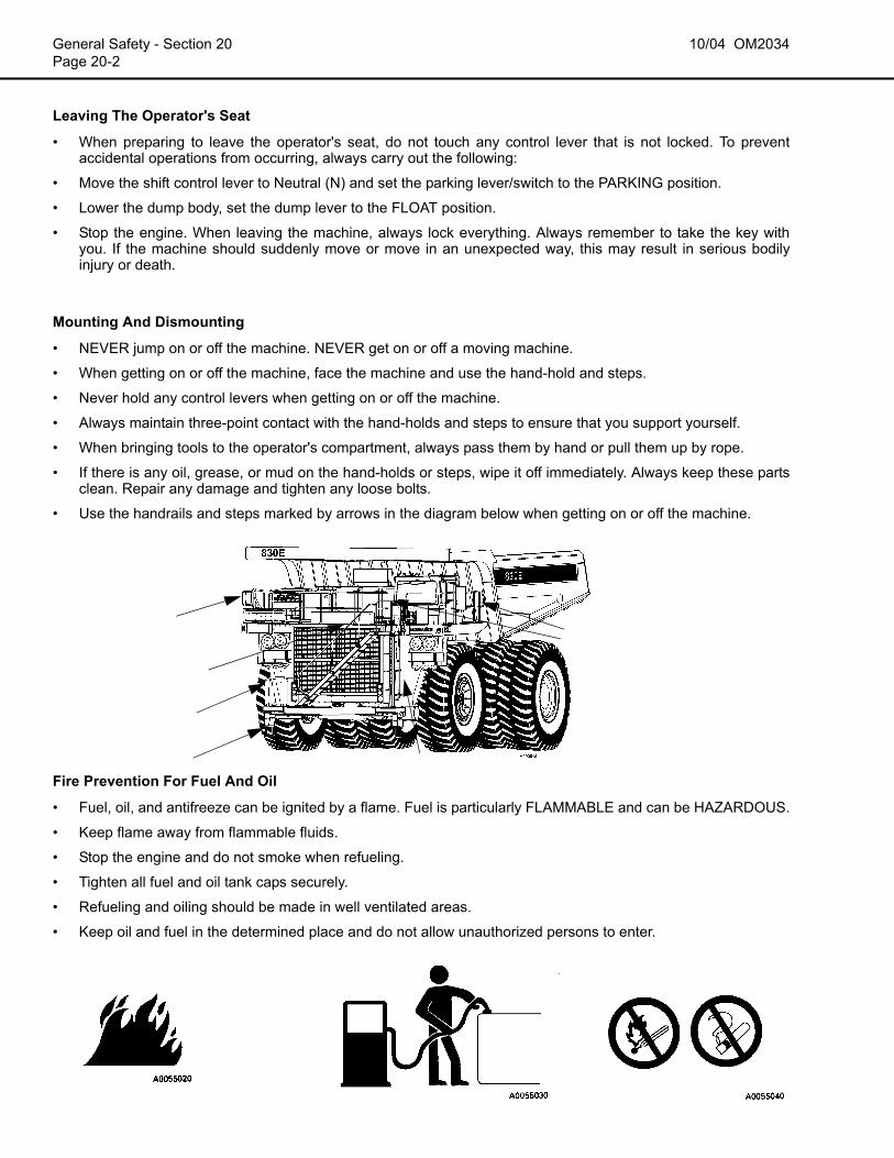
• Use the handrails and steps marked by arrows in the diagram below when getting on or off the machine.
Fire Prevention For Fuel And Oil
• Fuel, oil, and antifreeze can be ignited by a flame. Fuel is particularly FLAMMABLE and can be HAZARDOUS.
• Keep flame away from flammable fluids.
• Stop the engine and do not smoke when refueling.
• Tighten all fuel and oil tank caps securely.
• Refueling and oiling should be made in well ventilated areas.
• Keep oil and fuel in the determined place and do not allow unauthorized persons to enter.
OM2034 10/04 General Safety - Section 20Page 20-3
Precautions With High Temperature Fluids
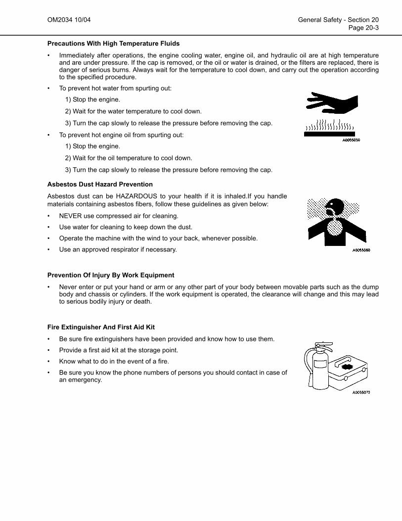
• Immediately after operations, the engine cooling water, engine oil, and hydraulic oil are at high temperatureand are under pressure. If the cap is removed, or the oil or water is drained, or the filters are replaced, there isdanger of serious burns. Always wait for the temperature to cool down, and carry out the operation accordingto the specified procedure.
• To prevent hot water from spurting out:
1) Stop the engine.
2) Wait for the water temperature to cool down.
3) Turn the cap slowly to release the pressure before removing the cap.
• To prevent hot engine oil from spurting out:
1) Stop the engine.
2) Wait for the oil temperature to cool down.
3) Turn the cap slowly to release the pressure before removing the cap.
Asbestos Dust Hazard Prevention
Asbestos dust can be HAZARDOUS to your health if it is inhaled.If you handlematerials containing asbestos fibers, follow these guidelines as given below:
• NEVER use compressed air for cleaning.
• Use water for cleaning to keep down the dust.
• Operate the machine with the wind to your back, whenever possible.
• Use an approved respirator if necessary.
Prevention Of Injury By Work Equipment
• Never enter or put your hand or arm or any other part of your body between movable parts such as the dumpbody and chassis or cylinders. If the work equipment is operated, the clearance will change and this may leadto serious bodily injury or death.
Fire Extinguisher And First Aid Kit
• Be sure fire extinguishers have been provided and know how to use them.
• Provide a first aid kit at the storage point.
• Know what to do in the event of a fire.
• Be sure you know the phone numbers of persons you should contact in case ofan emergency.
General Safety - Section 20 10/04 OM2034Page 20-4
Precautions When Using Rops
• If ROPS is installed, the ROPS must never be removed when operating the machine.
• The ROPS is installed to protect the operator if the machine should roll over. It is designed not only to supportthe load if the machine should roll over, but also to absorb the impact energy.
• The ROPS installed on equipment manufactured and designed by Komatsu fulfills all of the regulations andstandards for all countries, but if it is modified or repaired without authorization from Komatsu or is damagedwhen the machine rolls over, the strength will drop and it will not be able to fulfill its function properly. It canonly display its performance if it is repaired or modified in the specified way.
• When modifying or repairing the ROPS, always consult the authorized regional Komatsu distributor.
• Even if the ROPS is installed, it cannot show its full effect if the operator does not fasten the seat belt properly.Always fasten the seat belt when operating.
Precautions For Attachments
• When installing and using optional equipment, read the instruction manual for the attachment and theinformation related to attachments in this manual.
• Do not use attachments that are not authorized by Komatsu or the authorized regional Komatsu distributor.Use of unauthorized attachments could create a safety problem and adversely affect the proper operation anduseful life of the machine.
• Any injuries, accidents, and product failures resulting from the use of unauthorized attachments will not be theresponsibility of Komatsu, or the authorized regional Komatsu distributor.
Precautions For Starting Machine
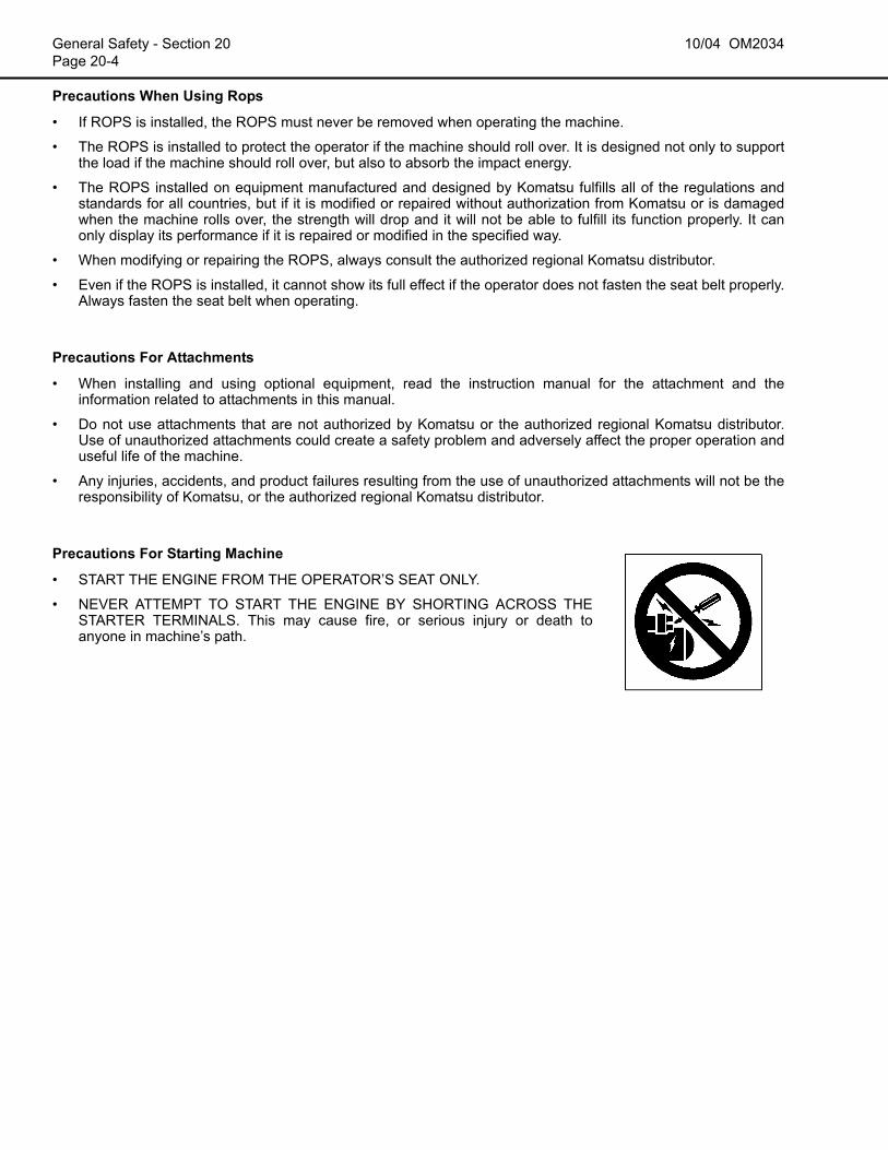
• START THE ENGINE FROM THE OPERATOR’S SEAT ONLY.
• NEVER ATTEMPT TO START THE ENGINE BY SHORTING ACROSS THESTARTER TERMINALS. This may cause fire, or serious injury or death toanyone in machine’s path.
OM2034 10/04 General Safety - Section 20Page 20-5
PRECAUTIONS DURING OPERATIONSafety Is Thinking Ahead
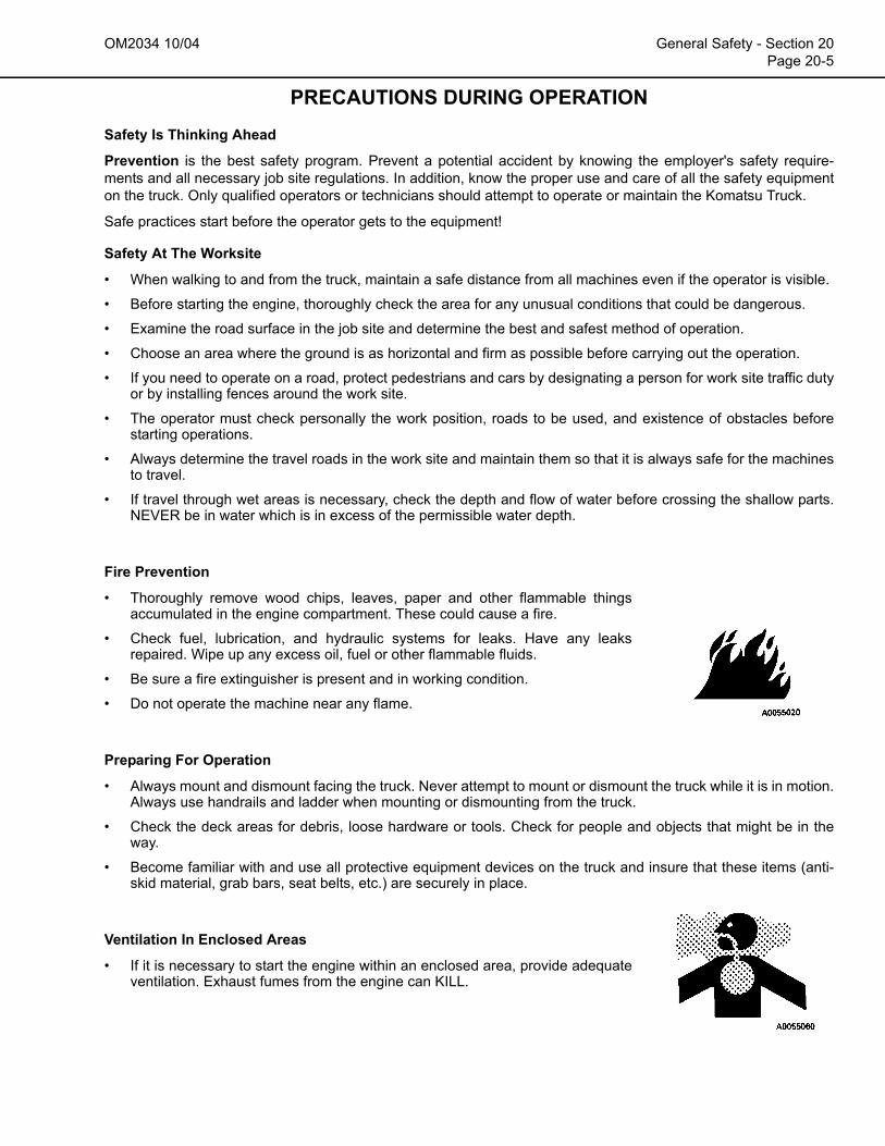
Prevention is the best safety program. Prevent a potential accident by knowing the employer's safety require-ments and all necessary job site regulations. In addition, know the proper use and care of all the safety equipmenton the truck. Only qualified operators or technicians should attempt to operate or maintain the Komatsu Truck.
Safe practices start before the operator gets to the equipment!
Safety At The Worksite
• When walking to and from the truck, maintain a safe distance from all machines even if the operator is visible.
• Before starting the engine, thoroughly check the area for any unusual conditions that could be dangerous.
• Examine the road surface in the job site and determine the best and safest method of operation.
• Choose an area where the ground is as horizontal and firm as possible before carrying out the operation.
• If you need to operate on a road, protect pedestrians and cars by designating a person for work site traffic dutyor by installing fences around the work site.
• The operator must check personally the work position, roads to be used, and existence of obstacles beforestarting operations.
• Always determine the travel roads in the work site and maintain them so that it is always safe for the machinesto travel.
• If travel through wet areas is necessary, check the depth and flow of water before crossing the shallow parts.NEVER be in water which is in excess of the permissible water depth.
Fire Prevention
• Thoroughly remove wood chips, leaves, paper and other flammable thingsaccumulated in the engine compartment. These could cause a fire.
• Check fuel, lubrication, and hydraulic systems for leaks. Have any leaksrepaired. Wipe up any excess oil, fuel or other flammable fluids.
• Be sure a fire extinguisher is present and in working condition.
• Do not operate the machine near any flame.
Preparing For Operation
• Always mount and dismount facing the truck. Never attempt to mount or dismount the truck while it is in motion.Always use handrails and ladder when mounting or dismounting from the truck.
• Check the deck areas for debris, loose hardware or tools. Check for people and objects that might be in theway.
• Become familiar with and use all protective equipment devices on the truck and insure that these items (anti-skid material, grab bars, seat belts, etc.) are securely in place.
Ventilation In Enclosed Areas
• If it is necessary to start the engine within an enclosed area, provide adequateventilation. Exhaust fumes from the engine can KILL.
General Safety - Section 20 10/04 OM2034Page 20-6
In Operator's Cab - Before Starting The Engine
• Do not leave tools or spare parts lying around in the operator's compartment or allow trash to accumulate incab of truck. Keep all unauthorized reading material out of truck cab.
• Keep the cab floor, controls, steps, and handrails free of oil, grease, snow, and excess dirt.
• Check the seat belt, buckle and hardware for damage or wear. Replace any worn or damaged parts. Alwaysuse seat belts when operating your machine.
• Read and understand the contents of this manual. Read Section 3 pertaining to safety and operatinginstructions with special attention. Become thoroughly acquainted with all gauges, instruments and controlsbefore attempting operation of the truck.
• Read and understand the WARNING and CAUTION decals in the operator's cab.
• Insure steering wheel, horn, controls and pedals are free of any oil, grease or mud.
• Check operation of windshield wiper, condition of wiper blades, and check washer reservoir for fluid level.
• Be familiar with all steering and brake system controls and warning devices, road speeds and loadingcapabilities, before operating the truck.
Mirrors, Windows, And Lights
• Remove any dirt from the surface of the windshield and all cab windows and lights. Good visibility may preventan accident.
• Adjust the rear view mirror to a position where the operator can see best from the operator's seat, and keep thesurface of the mirror clean. If any glass or light should break, replace it with a new part.
• Insure headlights, work lights and taillights are in proper working order. Check that the machine is equippedwith the head lamps and working lamps needed for the operating conditions.
OPERATING THE MACHINE
When Starting The Engine
• NEVER ATTEMPT TO START THE ENGINE BY SHORTING ACROSS THE STARTER TERMINALS. Thismay cause fire, or serious injury or death to anyone in machine’s path.
• NEVER start the engine if a warning tag has been attached to the control.
• When starting the engine, sound the horn as an alert.
• Start and operate the machine only while seated in the operator’s seat.
• Do not allow any person other than the operator in the operator's compartment or any other place on themachine.
Truck Operation - General
• WEAR SEAT BELTS AT ALL TIMES. • Only authorized persons are allowed to ride in truck. Riders should be in cab only and belted in passenger
seat.
• Do not allow anyone to ride on decks or steps of truck.
• Do not allow anyone to get on or off truck while it is in motion.
• Do not move truck into or out of a building without a signal person present.
• Know and obey the hand signal communications between operator and spotter. When other machines andpersonnel are present, the operator should move in and out of buildings, loading areas and through traffic,under the direction of a signal person. Courtesy at all times is a safety precaution!
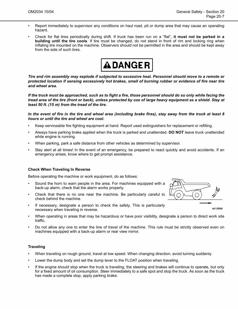
OM2034 10/04 General Safety - Section 20Page 20-7
• Report immediately to supervisor any conditions on haul road, pit or dump area that may cause an operatinghazard.
• Check for flat tires periodically during shift. If truck has been run on a “flat”, it must not be parked in abuilding until the tire cools. If tire must be changed, do not stand in front of rim and locking ring wheninflating tire mounted on the machine. Observers should not be permitted in the area and should be kept awayfrom the side of such tires.
Tire and rim assembly may explode if subjected to excessive heat. Personnel should move to a remote orprotected location if sensing excessively hot brakes, smell of burning rubber or evidence of fire near tireand wheel area.
If the truck must be approached, such as to fight a fire, those personnel should do so only while facing thetread area of the tire (front or back), unless protected by use of large heavy equipment as a shield. Stay atleast 50 ft. (15 m) from the tread of the tire.
In the event of fire in the tire and wheel area (including brake fires), stay away from the truck at least 8hours or until the tire and wheel are cool.
• Keep serviceable fire fighting equipment at hand. Report used extinguishers for replacement or refilling.
• Always have parking brake applied when the truck is parked and unattended. DO NOT leave truck unattendedwhile engine is running.
• When parking, park a safe distance from other vehicles as determined by supervisor.
• Stay alert at all times! In the event of an emergency, be prepared to react quickly and avoid accidents. If anemergency arises, know where to get prompt assistance.
Check When Traveling In Reverse
Before operating the machine or work equipment, do as follows:
• Sound the horn to warn people in the area. For machines equipped with aback-up alarm, check that the alarm works properly.
• Check that there is no one near the machine. Be particularly careful tocheck behind the machine.
• If necessary, designate a person to check the safety. This is particularlynecessary when traveling in reverse.
• When operating in areas that may be hazardous or have poor visibility, designate a person to direct work sitetraffic.
• Do not allow any one to enter the line of travel of the machine. This rule must be strictly observed even onmachines equipped with a back-up alarm or rear view mirror.
Traveling
• When traveling on rough ground, travel at low speed. When changing direction, avoid turning suddenly.
• Lower the dump body and set the dump lever to the FLOAT position when traveling.
• If the engine should stop when the truck is traveling, the steering and brakes will continue to operate, but onlyfor a fixed amount of oil consumption. Steer immediately to a safe spot and stop the truck. As soon as the truckhas made a complete stop, apply parking brake.
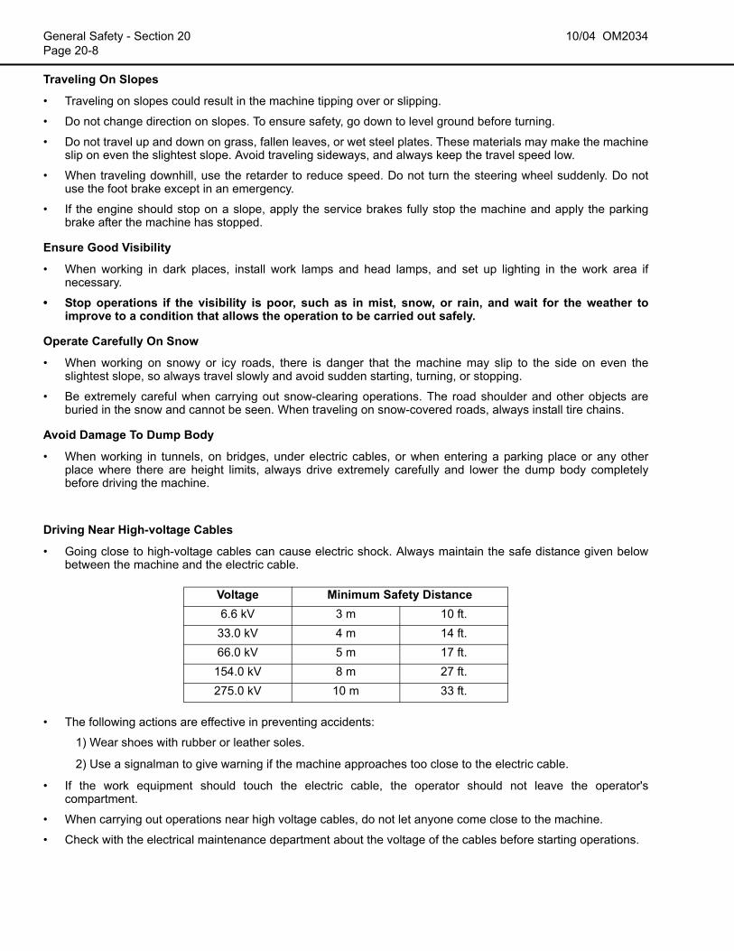
General Safety - Section 20 10/04 OM2034Page 20-8
Traveling On Slopes
• Traveling on slopes could result in the machine tipping over or slipping.
• Do not change direction on slopes. To ensure safety, go down to level ground before turning.
• Do not travel up and down on grass, fallen leaves, or wet steel plates. These materials may make the machineslip on even the slightest slope. Avoid traveling sideways, and always keep the travel speed low.
• When traveling downhill, use the retarder to reduce speed. Do not turn the steering wheel suddenly. Do notuse the foot brake except in an emergency.
• If the engine should stop on a slope, apply the service brakes fully stop the machine and apply the parkingbrake after the machine has stopped.
Ensure Good Visibility
• When working in dark places, install work lamps and head lamps, and set up lighting in the work area ifnecessary.
• Stop operations if the visibility is poor, such as in mist, snow, or rain, and wait for the weather toimprove to a condition that allows the operation to be carried out safely.
Operate Carefully On Snow
• When working on snowy or icy roads, there is danger that the machine may slip to the side on even theslightest slope, so always travel slowly and avoid sudden starting, turning, or stopping.
• Be extremely careful when carrying out snow-clearing operations. The road shoulder and other objects areburied in the snow and cannot be seen. When traveling on snow-covered roads, always install tire chains.
Avoid Damage To Dump Body
• When working in tunnels, on bridges, under electric cables, or when entering a parking place or any otherplace where there are height limits, always drive extremely carefully and lower the dump body completelybefore driving the machine.
Driving Near High-voltage Cables
• Going close to high-voltage cables can cause electric shock. Always maintain the safe distance given belowbetween the machine and the electric cable.
• The following actions are effective in preventing accidents:
1) Wear shoes with rubber or leather soles.
2) Use a signalman to give warning if the machine approaches too close to the electric cable.
• If the work equipment should touch the electric cable, the operator should not leave the operator'scompartment.
• When carrying out operations near high voltage cables, do not let anyone come close to the machine.
• Check with the electrical maintenance department about the voltage of the cables before starting operations.
Voltage Minimum Safety Distance6.6 kV 3 m 10 ft.
33.0 kV 4 m 14 ft.66.0 kV 5 m 17 ft.154.0 kV 8 m 27 ft.275.0 kV 10 m 33 ft.
OM2034 10/04 General Safety - Section 20Page 20-9
When Dumping
• Before starting the dumping operation, check that there is no person or object behind the machine.
• Stop the machine in the correct position, and check again that there is no person or object behind the machine.Give the determined signal, then slowly operate the dump body. If necessary, use blocks for the wheels orposition a flagman.
• When carrying out dumping operations on slopes, the machine stability will become poor and there is dangerthat it may tip over. Always carry out such operations extremely carefully.
• Do not travel with the dump body raised.
Working On Loose Ground
• Avoid operating the machine too close to the edge of cliffs, overhangs, and deep ditches. If these areascollapse, the machine could fall or tip over and result in serious injury or death. Remember that the soil afterheavy rain or blasting is weakened in these areas.
• Earth laid on the ground and the soil near ditches is loose. It can collapse under the weight or vibration of themachine. Avoid these areas, if possible.
When Loading
• Check that the surrounding area is safe, stop the machine in the correct loading position, then load the bodyuniformly.
• Do not leave the operator's seat during the loading operation.
Parking The Machine
• Choose a horizontal road surface to park the machine. If the machine has to be parked on a slope, always putblocks under all the wheels to prevent the machine from moving.
• When parking on public roads, provide fences and signs, such as flags or lights, on the machine to warnpedestrians and other vehicles. Be sure that the machine, flags, or lights do not obstruct the traffic.
• Before leaving the machine, lower the dump body fully, set the parking lever to the PARKING position, stop theengine, then lock everything. Always take the key with you.
TOWING• When towing, fix wire to hook.
• Towing in the wrong way may lead to serious personal injury or damage.
• When using another machine to tow this machine, use a towing device with ample strength for the weight ofthis machine.
• Never tow a machine on a slope.
• Do not use any towing rope that has kinks or is twisted.
• Do not stand astride the towing cable or wire rope.
• When connecting a machine that is to be towed, do not let any one come between the towing machine and themachine that is being towed.
• Set the coupling of the machine being towed in a straight line with the towing portion of the machine, andsecure it in position.
(For towing method, see Section 3, “Operating Instructions, TOWING”.)
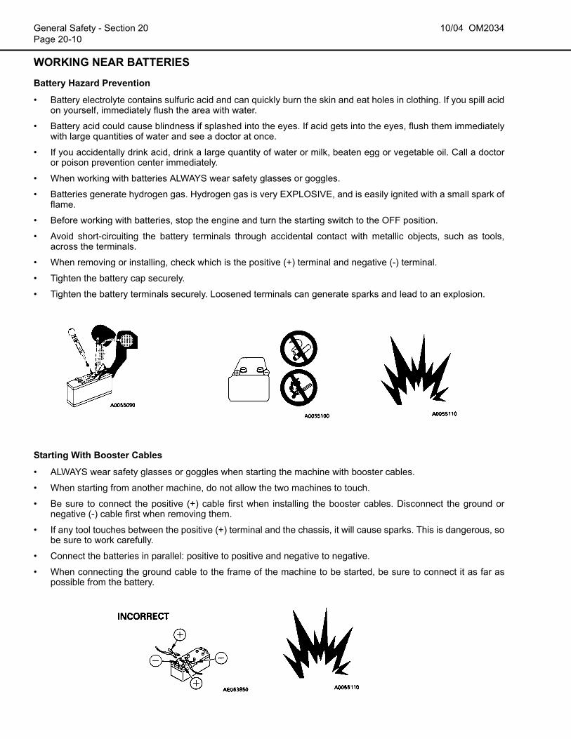
General Safety - Section 20 10/04 OM2034Page 20-10
WORKING NEAR BATTERIES
Battery Hazard Prevention
• Battery electrolyte contains sulfuric acid and can quickly burn the skin and eat holes in clothing. If you spill acidon yourself, immediately flush the area with water.
• Battery acid could cause blindness if splashed into the eyes. If acid gets into the eyes, flush them immediatelywith large quantities of water and see a doctor at once.
• If you accidentally drink acid, drink a large quantity of water or milk, beaten egg or vegetable oil. Call a doctoror poison prevention center immediately.
• When working with batteries ALWAYS wear safety glasses or goggles.
• Batteries generate hydrogen gas. Hydrogen gas is very EXPLOSIVE, and is easily ignited with a small spark offlame.
• Before working with batteries, stop the engine and turn the starting switch to the OFF position.
• Avoid short-circuiting the battery terminals through accidental contact with metallic objects, such as tools,across the terminals.
• When removing or installing, check which is the positive (+) terminal and negative (-) terminal.
• Tighten the battery cap securely.
• Tighten the battery terminals securely. Loosened terminals can generate sparks and lead to an explosion.
Starting With Booster Cables
• ALWAYS wear safety glasses or goggles when starting the machine with booster cables.
• When starting from another machine, do not allow the two machines to touch.
• Be sure to connect the positive (+) cable first when installing the booster cables. Disconnect the ground ornegative (-) cable first when removing them.
• If any tool touches between the positive (+) terminal and the chassis, it will cause sparks. This is dangerous, sobe sure to work carefully.
• Connect the batteries in parallel: positive to positive and negative to negative.
• When connecting the ground cable to the frame of the machine to be started, be sure to connect it as far aspossible from the battery.
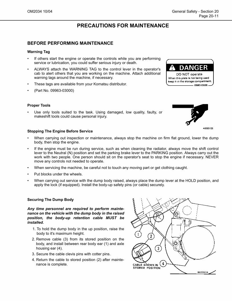
OM2034 10/04 General Safety - Section 20Page 20-11
PRECAUTIONS FOR MAINTENANCE
BEFORE PERFORMING MAINTENANCE
Warning Tag
• If others start the engine or operate the controls while you are performingservice or lubrication, you could suffer serious injury or death.
• ALWAYS attach the WARNING TAG to the control lever in the operator'scab to alert others that you are working on the machine. Attach additionalwarning tags around the machine, if necessary.
• These tags are available from your Komatsu distributor.
• (Part No. 09963-03000)
Proper Tools
• Use only tools suited to the task. Using damaged, low quality, faulty, ormakeshift tools could cause personal injury.
Stopping The Engine Before Service
• When carrying out inspection or maintenance, always stop the machine on firm flat ground, lower the dumpbody, then stop the engine.
• If the engine must be run during service, such as when cleaning the radiator, always move the shift controllever to the Neutral (N) position and set the parking brake lever to the PARKING position. Always carry out thework with two people. One person should sit on the operator's seat to stop the engine if necessary. NEVERmove any controls not needed to operate.
• When servicing the machine, be careful not to touch any moving part or get clothing caught.
• Put blocks under the wheels.
• When carrying out service with the dump body raised, always place the dump lever at the HOLD position, andapply the lock (if equipped). Install the body-up safety pins (or cable) securely.
Securing The Dump Body
Any time personnel are required to perform mainte-nance on the vehicle with the dump body in the raisedposition, the body-up retention cable MUST beinstalled.
1. To hold the dump body in the up position, raise thebody to it's maximum height.
2. Remove cable (3) from its stored position on thebody, and install between rear body ear (1) and axlehousing ear (4).
3. Secure the cable clevis pins with cotter pins.4. Return the cable to stored position (2) after mainte-
nance is complete.
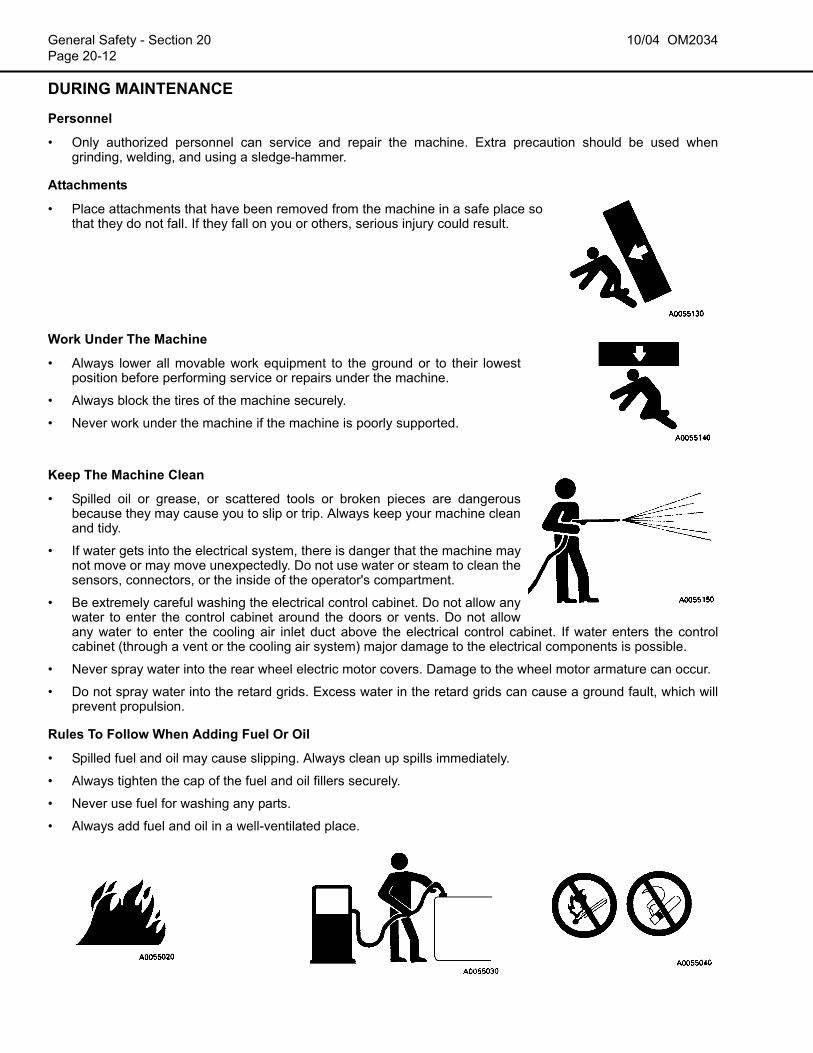
General Safety - Section 20 10/04 OM2034Page 20-12
DURING MAINTENANCE
Personnel
• Only authorized personnel can service and repair the machine. Extra precaution should be used whengrinding, welding, and using a sledge-hammer.
Attachments
• Place attachments that have been removed from the machine in a safe place sothat they do not fall. If they fall on you or others, serious injury could result.
Work Under The Machine
• Always lower all movable work equipment to the ground or to their lowestposition before performing service or repairs under the machine.
• Always block the tires of the machine securely.
• Never work under the machine if the machine is poorly supported.
Keep The Machine Clean
• Spilled oil or grease, or scattered tools or broken pieces are dangerousbecause they may cause you to slip or trip. Always keep your machine cleanand tidy.
• If water gets into the electrical system, there is danger that the machine maynot move or may move unexpectedly. Do not use water or steam to clean thesensors, connectors, or the inside of the operator's compartment.
• Be extremely careful washing the electrical control cabinet. Do not allow anywater to enter the control cabinet around the doors or vents. Do not allowany water to enter the cooling air inlet duct above the electrical control cabinet. If water enters the controlcabinet (through a vent or the cooling air system) major damage to the electrical components is possible.
• Never spray water into the rear wheel electric motor covers. Damage to the wheel motor armature can occur.
• Do not spray water into the retard grids. Excess water in the retard grids can cause a ground fault, which willprevent propulsion.
Rules To Follow When Adding Fuel Or Oil
• Spilled fuel and oil may cause slipping. Always clean up spills immediately.
• Always tighten the cap of the fuel and oil fillers securely.
• Never use fuel for washing any parts.
• Always add fuel and oil in a well-ventilated place.
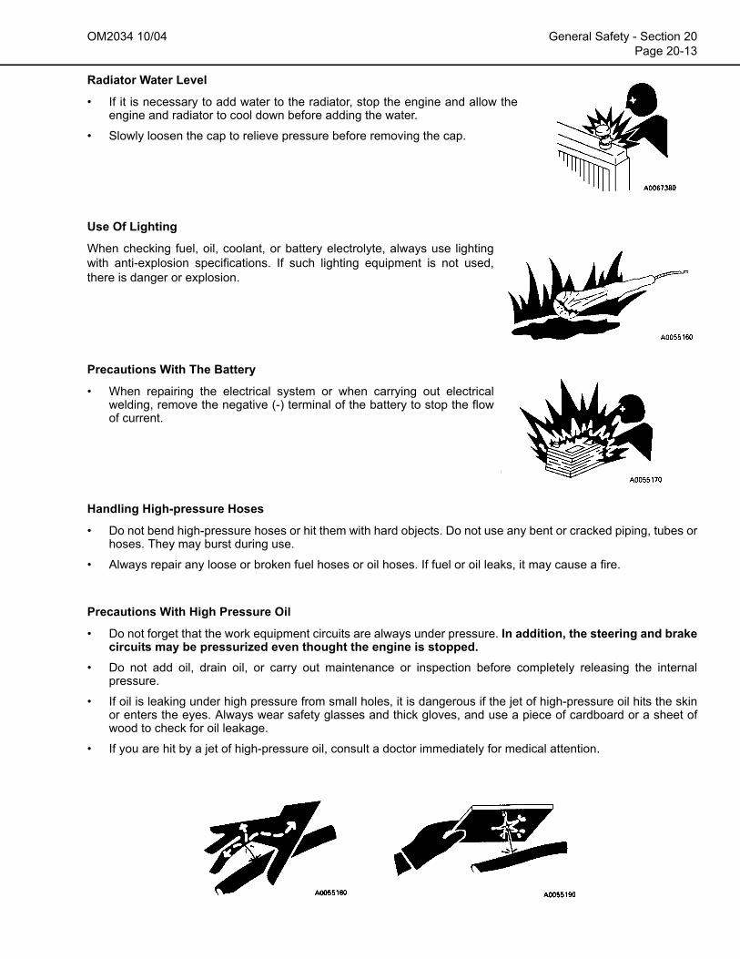
OM2034 10/04 General Safety - Section 20Page 20-13
Radiator Water Level
• If it is necessary to add water to the radiator, stop the engine and allow theengine and radiator to cool down before adding the water.
• Slowly loosen the cap to relieve pressure before removing the cap.
Use Of Lighting
When checking fuel, oil, coolant, or battery electrolyte, always use lightingwith anti-explosion specifications. If such lighting equipment is not used,there is danger or explosion.
Precautions With The Battery
• When repairing the electrical system or when carrying out electricalwelding, remove the negative (-) terminal of the battery to stop the flowof current.
Handling High-pressure Hoses
• Do not bend high-pressure hoses or hit them with hard objects. Do not use any bent or cracked piping, tubes orhoses. They may burst during use.
• Always repair any loose or broken fuel hoses or oil hoses. If fuel or oil leaks, it may cause a fire.
Precautions With High Pressure Oil
• Do not forget that the work equipment circuits are always under pressure. In addition, the steering and brakecircuits may be pressurized even thought the engine is stopped.
• Do not add oil, drain oil, or carry out maintenance or inspection before completely releasing the internalpressure.
• If oil is leaking under high pressure from small holes, it is dangerous if the jet of high-pressure oil hits the skinor enters the eyes. Always wear safety glasses and thick gloves, and use a piece of cardboard or a sheet ofwood to check for oil leakage.
• If you are hit by a jet of high-pressure oil, consult a doctor immediately for medical attention.
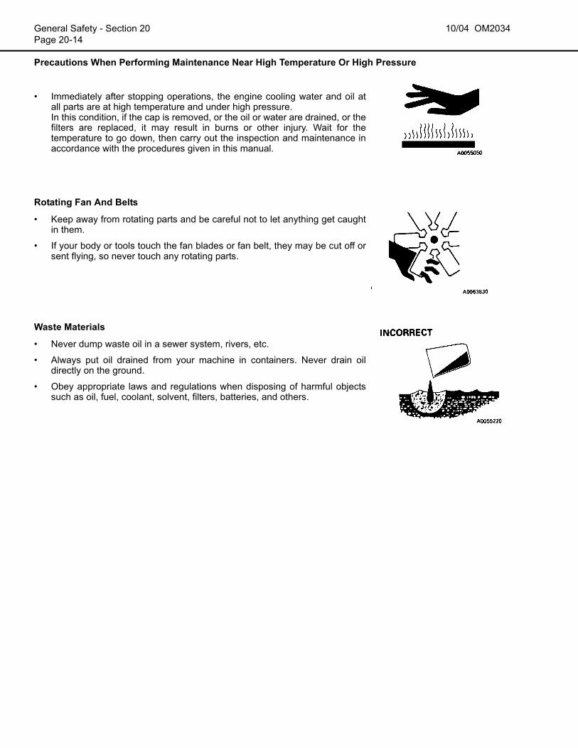
General Safety - Section 20 10/04 OM2034Page 20-14
Precautions When Performing Maintenance Near High Temperature Or High Pressure
• Immediately after stopping operations, the engine cooling water and oil atall parts are at high temperature and under high pressure.In this condition, if the cap is removed, or the oil or water are drained, or thefilters are replaced, it may result in burns or other injury. Wait for thetemperature to go down, then carry out the inspection and maintenance inaccordance with the procedures given in this manual.
Rotating Fan And Belts
• Keep away from rotating parts and be careful not to let anything get caughtin them.
• If your body or tools touch the fan blades or fan belt, they may be cut off orsent flying, so never touch any rotating parts.
Waste Materials
• Never dump waste oil in a sewer system, rivers, etc.
• Always put oil drained from your machine in containers. Never drain oildirectly on the ground.
• Obey appropriate laws and regulations when disposing of harmful objectssuch as oil, fuel, coolant, solvent, filters, batteries, and others.
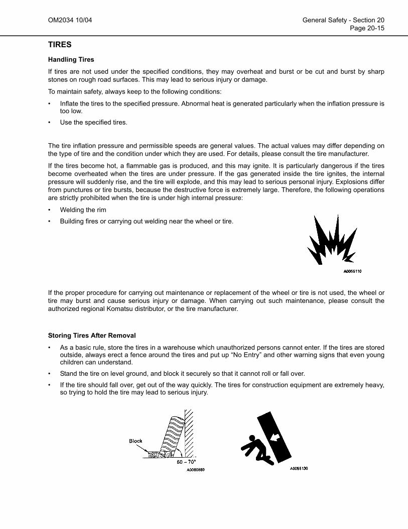
OM2034 10/04 General Safety - Section 20Page 20-15
TIRES
Handling Tires
If tires are not used under the specified conditions, they may overheat and burst or be cut and burst by sharpstones on rough road surfaces. This may lead to serious injury or damage.
To maintain safety, always keep to the following conditions:
• Inflate the tires to the specified pressure. Abnormal heat is generated particularly when the inflation pressure istoo low.
• Use the specified tires.
The tire inflation pressure and permissible speeds are general values. The actual values may differ depending onthe type of tire and the condition under which they are used. For details, please consult the tire manufacturer.
If the tires become hot, a flammable gas is produced, and this may ignite. It is particularly dangerous if the tiresbecome overheated when the tires are under pressure. If the gas generated inside the tire ignites, the internalpressure will suddenly rise, and the tire will explode, and this may lead to serious personal injury. Explosions differfrom punctures or tire bursts, because the destructive force is extremely large. Therefore, the following operationsare strictly prohibited when the tire is under high internal pressure:
• Welding the rim
• Building fires or carrying out welding near the wheel or tire.
If the proper procedure for carrying out maintenance or replacement of the wheel or tire is not used, the wheel ortire may burst and cause serious injury or damage. When carrying out such maintenance, please consult theauthorized regional Komatsu distributor, or the tire manufacturer.
Storing Tires After Removal
• As a basic rule, store the tires in a warehouse which unauthorized persons cannot enter. If the tires are storedoutside, always erect a fence around the tires and put up “No Entry” and other warning signs that even youngchildren can understand.
• Stand the tire on level ground, and block it securely so that it cannot roll or fall over.
• If the tire should fall over, get out of the way quickly. The tires for construction equipment are extremely heavy,so trying to hold the tire may lead to serious injury.

General Safety - Section 20 10/04 OM2034Page 20-16
ADDITIONAL JOB SITE RULES• Use this space to add any ADDITIONAL Job Site Rules not covered in any of the previous discussions.
• _______________________________________________________________________________________
• _______________________________________________________________________________________
• _______________________________________________________________________________________
• _______________________________________________________________________________________
• _______________________________________________________________________________________
• _______________________________________________________________________________________
• _______________________________________________________________________________________
• _______________________________________________________________________________________
• _______________________________________________________________________________________
• _______________________________________________________________________________________
• _______________________________________________________________________________________
• _______________________________________________________________________________________
• _______________________________________________________________________________________
• _______________________________________________________________________________________
• _______________________________________________________________________________________
• _______________________________________________________________________________________
• _______________________________________________________________________________________
• _______________________________________________________________________________________
• _______________________________________________________________________________________
• _______________________________________________________________________________________
• _______________________________________________________________________________________
• _______________________________________________________________________________________
• _______________________________________________________________________________________
• _______________________________________________________________________________________
• _______________________________________________________________________________________
• _______________________________________________________________________________________
• _______________________________________________________________________________________
• _______________________________________________________________________________________
• _______________________________________________________________________________________
• _______________________________________________________________________________________
• _______________________________________________________________________________________
• _______________________________________________________________________________________
• _______________________________________________________________________________________
• _______________________________________________________________________________________
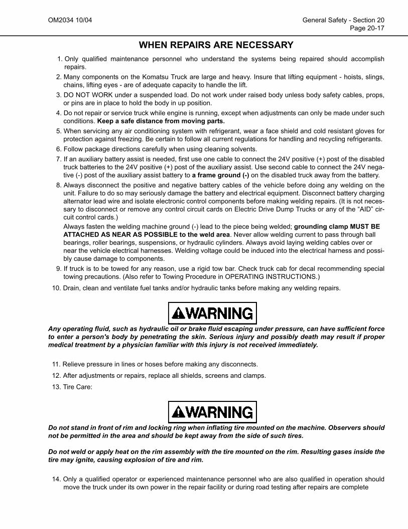
OM2034 10/04 General Safety - Section 20Page 20-17
WHEN REPAIRS ARE NECESSARY1. Only qualified maintenance personnel who understand the systems being repaired should accomplish
repairs.2. Many components on the Komatsu Truck are large and heavy. Insure that lifting equipment - hoists, slings,
chains, lifting eyes - are of adequate capacity to handle the lift.3. DO NOT WORK under a suspended load. Do not work under raised body unless body safety cables, props,
or pins are in place to hold the body in up position.4. Do not repair or service truck while engine is running, except when adjustments can only be made under such
conditions. Keep a safe distance from moving parts.5. When servicing any air conditioning system with refrigerant, wear a face shield and cold resistant gloves for
protection against freezing. Be certain to follow all current regulations for handling and recycling refrigerants.6. Follow package directions carefully when using cleaning solvents.7. If an auxiliary battery assist is needed, first use one cable to connect the 24V positive (+) post of the disabled
truck batteries to the 24V positive (+) post of the auxiliary assist. Use second cable to connect the 24V nega-tive (-) post of the auxiliary assist battery to a frame ground (-) on the disabled truck away from the battery.
8. Always disconnect the positive and negative battery cables of the vehicle before doing any welding on theunit. Failure to do so may seriously damage the battery and electrical equipment. Disconnect battery chargingalternator lead wire and isolate electronic control components before making welding repairs. (It is not neces-sary to disconnect or remove any control circuit cards on Electric Drive Dump Trucks or any of the “AID” cir-cuit control cards.) Always fasten the welding machine ground (-) lead to the piece being welded; grounding clamp MUST BE ATTACHED AS NEAR AS POSSIBLE to the weld area. Never allow welding current to pass through ball bearings, roller bearings, suspensions, or hydraulic cylinders. Always avoid laying welding cables over or near the vehicle electrical harnesses. Welding voltage could be induced into the electrical harness and possi-bly cause damage to components.
9. If truck is to be towed for any reason, use a rigid tow bar. Check truck cab for decal recommending specialtowing precautions. (Also refer to Towing Procedure in OPERATING INSTRUCTIONS.)
10. Drain, clean and ventilate fuel tanks and/or hydraulic tanks before making any welding repairs.
Any operating fluid, such as hydraulic oil or brake fluid escaping under pressure, can have sufficient forceto enter a person's body by penetrating the skin. Serious injury and possibly death may result if propermedical treatment by a physician familiar with this injury is not received immediately.
11. Relieve pressure in lines or hoses before making any disconnects.
12. After adjustments or repairs, replace all shields, screens and clamps.
13. Tire Care:
Do not stand in front of rim and locking ring when inflating tire mounted on the machine. Observers shouldnot be permitted in the area and should be kept away from the side of such tires.
Do not weld or apply heat on the rim assembly with the tire mounted on the rim. Resulting gases inside thetire may ignite, causing explosion of tire and rim.
14. Only a qualified operator or experienced maintenance personnel who are also qualified in operation shouldmove the truck under its own power in the repair facility or during road testing after repairs are complete

General Safety - Section 20 10/04 OM2034Page 20-18
NOTES
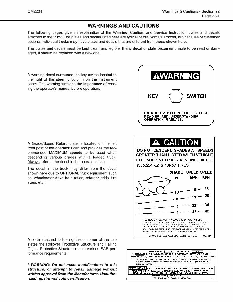
OM2204 Warnings & Cautions - Section 22Page 22-1
WARNINGS AND CAUTIONS
A warning decal surrounds the key switch located tothe right of the steering column on the instrumentpanel. The warning stresses the importance of read-ing the operator's manual before operation.
A Grade/Speed Retard plate is located on the leftfront post of the operator's cab and provides the rec-ommended MAXIMUM speeds to be used whendescending various grades with a loaded truck.Always refer to the decal in the operator's cab.
The decal in the truck may differ from the decalshown here due to OPTIONAL truck equipment suchas: wheelmotor drive train ratios, retarder grids, tiresizes, etc.
A plate attached to the right rear corner of the cabstates the Rollover Protective Structure and FallingObject Protective Structure meets various SAE per-formance requirements.
! WARNING! Do not make modifications to thisstructure, or attempt to repair damage withoutwritten approval from the Manufacturer. Unautho-rized repairs will void certification.
The following pages give an explanation of the Warning, Caution, and Service Instruction plates and decalsattached to the truck. The plates and decals listed here are typical of this Komatsu model, but because of customeroptions, individual trucks may have plates and decals that are different from those shown here.
The plates and decals must be kept clean and legible. If any decal or plate becomes unable to be read or dam-aged, it should be replaced with a new one.
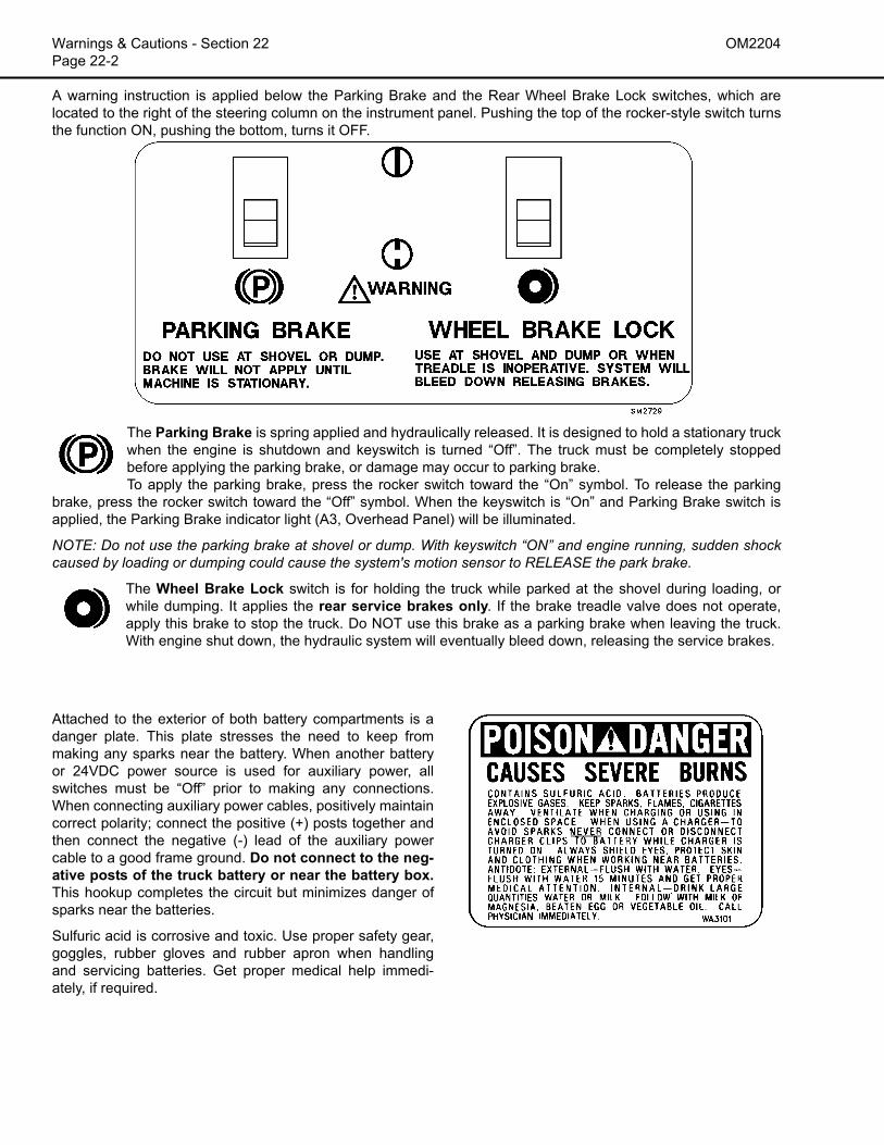
Warnings & Cautions - Section 22 OM2204Page 22-2
A warning instruction is applied below the Parking Brake and the Rear Wheel Brake Lock switches, which arelocated to the right of the steering column on the instrument panel. Pushing the top of the rocker-style switch turnsthe function ON, pushing the bottom, turns it OFF.
The Parking Brake is spring applied and hydraulically released. It is designed to hold a stationary truckwhen the engine is shutdown and keyswitch is turned “Off”. The truck must be completely stoppedbefore applying the parking brake, or damage may occur to parking brake. To apply the parking brake, press the rocker switch toward the “On” symbol. To release the parking
brake, press the rocker switch toward the “Off” symbol. When the keyswitch is “On” and Parking Brake switch isapplied, the Parking Brake indicator light (A3, Overhead Panel) will be illuminated.
NOTE: Do not use the parking brake at shovel or dump. With keyswitch “ON” and engine running, sudden shockcaused by loading or dumping could cause the system's motion sensor to RELEASE the park brake.
The Wheel Brake Lock switch is for holding the truck while parked at the shovel during loading, orwhile dumping. It applies the rear service brakes only. If the brake treadle valve does not operate,apply this brake to stop the truck. Do NOT use this brake as a parking brake when leaving the truck.With engine shut down, the hydraulic system will eventually bleed down, releasing the service brakes.
Attached to the exterior of both battery compartments is adanger plate. This plate stresses the need to keep frommaking any sparks near the battery. When another batteryor 24VDC power source is used for auxiliary power, allswitches must be “Off” prior to making any connections.When connecting auxiliary power cables, positively maintaincorrect polarity; connect the positive (+) posts together andthen connect the negative (-) lead of the auxiliary powercable to a good frame ground. Do not connect to the neg-ative posts of the truck battery or near the battery box.This hookup completes the circuit but minimizes danger ofsparks near the batteries.
Sulfuric acid is corrosive and toxic. Use proper safety gear,goggles, rubber gloves and rubber apron when handlingand servicing batteries. Get proper medical help immedi-ately, if required.
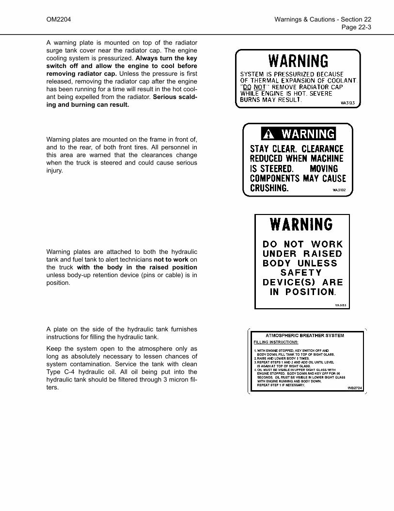
OM2204 Warnings & Cautions - Section 22Page 22-3
A warning plate is mounted on top of the radiatorsurge tank cover near the radiator cap. The enginecooling system is pressurized. Always turn the keyswitch off and allow the engine to cool beforeremoving radiator cap. Unless the pressure is firstreleased, removing the radiator cap after the enginehas been running for a time will result in the hot cool-ant being expelled from the radiator. Serious scald-ing and burning can result.
Warning plates are mounted on the frame in front of,and to the rear, of both front tires. All personnel inthis area are warned that the clearances changewhen the truck is steered and could cause seriousinjury.
Warning plates are attached to both the hydraulictank and fuel tank to alert technicians not to work onthe truck with the body in the raised positionunless body-up retention device (pins or cable) is inposition.
A plate on the side of the hydraulic tank furnishesinstructions for filling the hydraulic tank.
Keep the system open to the atmosphere only aslong as absolutely necessary to lessen chances ofsystem contamination. Service the tank with cleanType C-4 hydraulic oil. All oil being put into thehydraulic tank should be filtered through 3 micron fil-ters.
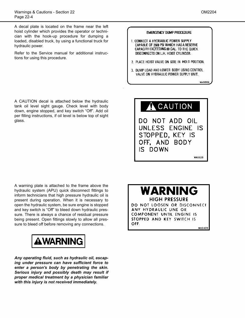
Warnings & Cautions - Section 22 OM2204Page 22-4
A decal plate is located on the frame near the lefthoist cylinder which provides the operator or techni-cian with the hook-up procedure for dumping aloaded, disabled truck, by using a functional truck forhydraulic power.
Refer to the Service manual for additional instruc-tions for using this procedure.
A CAUTION decal is attached below the hydraulictank oil level sight gauge. Check level with bodydown, engine stopped, and key switch “Off”. Add oilper filling instructions, if oil level is below top of sightglass.
A warning plate is attached to the frame above thehydraulic system (APU) quick disconnect fittings toinform technicians that high pressure hydraulic oil ispresent during operation. When it is necessary toopen the hydraulic system, be sure engine is stoppedand key switch is “Off” to bleed down hydraulic pres-sure. There is always a chance of residual pressurebeing present. Open fittings slowly to allow all pres-sure to bleed off before removing any connections.
Any operating fluid, such as hydraulic oil, escap-ing under pressure can have sufficient force toenter a person's body by penetrating the skin.Serious injury and possibly death may result ifproper medical treatment by a physician familiarwith this injury is not received immediately.
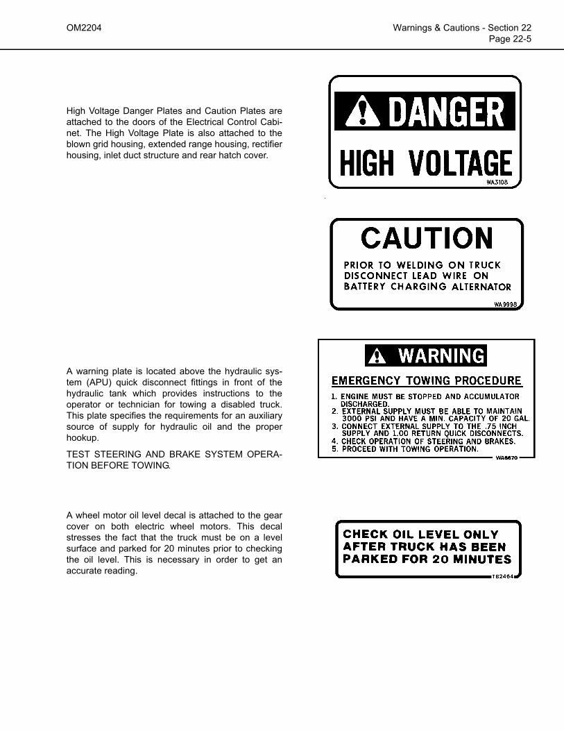
OM2204 Warnings & Cautions - Section 22Page 22-5
High Voltage Danger Plates and Caution Plates areattached to the doors of the Electrical Control Cabi-net. The High Voltage Plate is also attached to theblown grid housing, extended range housing, rectifierhousing, inlet duct structure and rear hatch cover.
A warning plate is located above the hydraulic sys-tem (APU) quick disconnect fittings in front of thehydraulic tank which provides instructions to theoperator or technician for towing a disabled truck.This plate specifies the requirements for an auxiliarysource of supply for hydraulic oil and the properhookup.
TEST STEERING AND BRAKE SYSTEM OPERA-TION BEFORE TOWING.
A wheel motor oil level decal is attached to the gearcover on both electric wheel motors. This decalstresses the fact that the truck must be on a levelsurface and parked for 20 minutes prior to checkingthe oil level. This is necessary in order to get anaccurate reading.
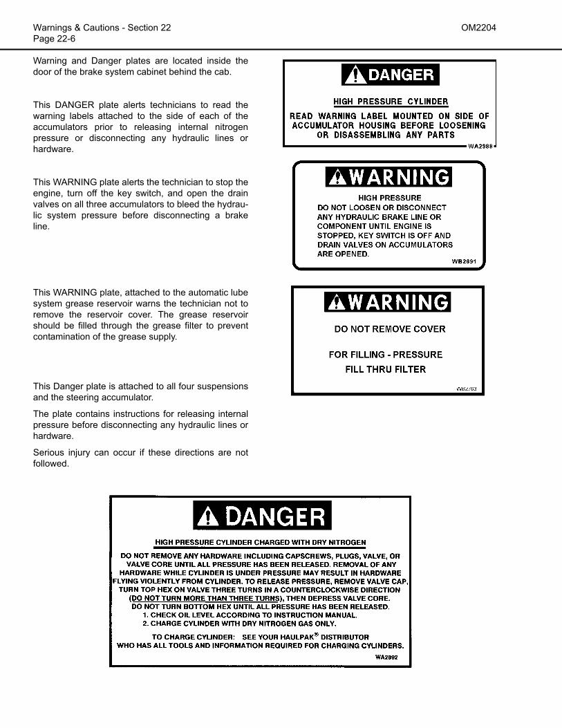
Warnings & Cautions - Section 22 OM2204Page 22-6
Warning and Danger plates are located inside thedoor of the brake system cabinet behind the cab.
This DANGER plate alerts technicians to read thewarning labels attached to the side of each of theaccumulators prior to releasing internal nitrogenpressure or disconnecting any hydraulic lines orhardware.
This WARNING plate alerts the technician to stop theengine, turn off the key switch, and open the drainvalves on all three accumulators to bleed the hydrau-lic system pressure before disconnecting a brakeline.
This WARNING plate, attached to the automatic lubesystem grease reservoir warns the technician not toremove the reservoir cover. The grease reservoirshould be filled through the grease filter to preventcontamination of the grease supply.
This Danger plate is attached to all four suspensionsand the steering accumulator.
The plate contains instructions for releasing internalpressure before disconnecting any hydraulic lines orhardware.
Serious injury can occur if these directions are notfollowed.
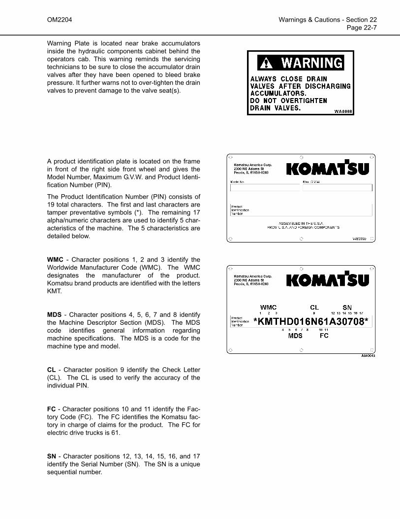
OM2204 Warnings & Cautions - Section 22Page 22-7
Warning Plate is located near brake accumulatorsinside the hydraulic components cabinet behind theoperators cab. This warning reminds the servicingtechnicians to be sure to close the accumulator drainvalves after they have been opened to bleed brakepressure. It further warns not to over-tighten the drainvalves to prevent damage to the valve seat(s).
A product identification plate is located on the framein front of the right side front wheel and gives theModel Number, Maximum G.V.W. and Product Identi-fication Number (PIN).
The Product Identification Number (PIN) consists of19 total characters. The first and last characters aretamper preventative symbols (*). The remaining 17alpha/numeric characters are used to identify 5 char-acteristics of the machine. The 5 characteristics aredetailed below.
WMC - Character positions 1, 2 and 3 identify theWorldwide Manufacturer Code (WMC). The WMCdesignates the manufacturer of the product.Komatsu brand products are identified with the lettersKMT.
MDS - Character positions 4, 5, 6, 7 and 8 identifythe Machine Descriptor Section (MDS). The MDScode identifies general information regardingmachine specifications. The MDS is a code for themachine type and model.
CL - Character position 9 identify the Check Letter(CL). The CL is used to verify the accuracy of theindividual PIN.
FC - Character positions 10 and 11 identify the Fac-tory Code (FC). The FC identifies the Komatsu fac-tory in charge of claims for the product. The FC forelectric drive trucks is 61.
SN - Character positions 12, 13, 14, 15, 16, and 17identify the Serial Number (SN). The SN is a uniquesequential number.
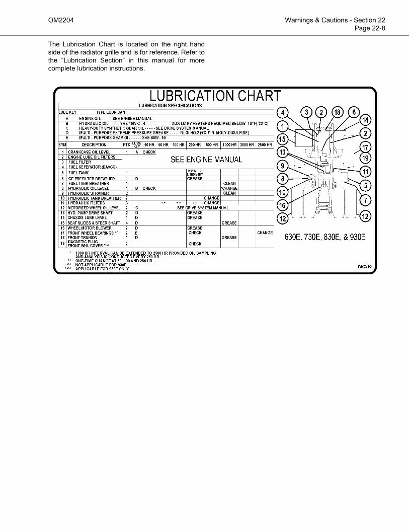
OM2204 Warnings & Cautions - Section 22Page 22-8
The Lubrication Chart is located on the right handside of the radiator grille and is for reference. Refer tothe “Lubrication Section” in this manual for morecomplete lubrication instructions.
OM3044 Operating Instructions - Section 30Page 30-1
OPERATING INSTRUCTIONS
PREPARING FOR OPERATIONThe safest trucks are those which have been properlyprepared for operation. At the beginning of each shift, acareful check of the truck should be made by the oper-ator before attempting to start the engine.
Safety Is Thinking Ahead
Prevention is the best safety program. Prevent poten-tial accidents by knowing all of the employer's safetyrequirements, all necessary job site regulations, as wellas the use and care of the safety equipment on thetruck. Only qualified operators or technicians shouldattempt to operate or maintain the truck.
Safe practices start before the operator gets to theequipment!
• Wear the proper clothing. Loose fitting clothing, unbuttoned sleeves and jackets, jewelry, etc., can catch on a protrusion and cause a potential hazard.
• Always use the personal safety equipment pro-vided for the operator such as hard hat, safety shoes, safety glasses or goggles. There are some conditions when protective hearing devices should also be worn for operator safety.
• When walking to and from the truck, maintain a safe distance from all machines even if the operator is visible.
At The Truck - Ground Level Walk Around Inspec-tion
At the beginning of each shift, a careful walk aroundinspection of the truck should be made before the oper-ator attempts engine start-up. A walk around inspectionis a systematic ground level inspection of the truck andits components to insure that the truck is safe to oper-ate before entering the operator's cab.
Start at the left front corner of the truck (see illustration,next page), and move in a counter-clockwise direction,front-to-rear, across the rear, and continuing forwardup the opposite side of the truck to the original startingpoint.
If these steps are taken in sequence, and are repeatedfrom the same point and in the same direction beforeevery shift, many potential problems may be avoided,or scheduled for maintenance. UNSCHEDULED down-time and loss of production can be reduced.
Local work practices may prevent an operator fromperforming all tasks suggested here, but to the extentpermitted, the operator should follow this or similar rou-tine.
1. Start at left front of truck (see illustration, nextpage). While performing the walk around inspec-tion, visually inspect all lights and safety equip-ment for external damage from rocks or misuse.Make sure lenses are clean and unbroken.
Empty the dust pans on the left side air cleanerassemblies.
2. Move behind the front of the left front tire, inspectthe hub and brake assemblies for leaks and anyabnormal conditions.
Check that all suspension attaching hardware issecure, the suspension extension is correct, andthat there are no leaks.
3. With engine stopped, swing access ladder down.If dark, turn on service light located to the right,just above ladder by hand rail. Check engine oillevel.
4. Inspect fan and air conditioner belts for correcttension, obvious wear, and tracking. Inspect fanguard for security and condition. When leavingthis point, be sure ladder is up and secure, andturn service light(s) OFF, if used.
5. Inspect anchor end of steering cylinder for propergreasing and for security.
6. Move outboard of the front wheel, and inspectattaching lugs/wedges to be sure all are tight andcomplete. Check tires for cuts, damage or “bub-bles” and that inflation appears to be correct.Check sight glass for front wheel oil level.
7. Move behind the rear of the front wheel, inspectfor leaks at hub or brakes or any unusual condi-tions. Inspect suspension hardware to be sure it isall in place. Inspect live end of steering cylinderfor proper greasing, and for security of all parts.Inspect for any hydraulic leaks.
Swing hydraulic tank inspection ladder down.Inspect sight glass on hydraulic reservoir, engineshould be stopped and body down, and fluidshould appear in lower sight glass.
8. Before leaving hydraulic tank be sure that ladderis up and secure.
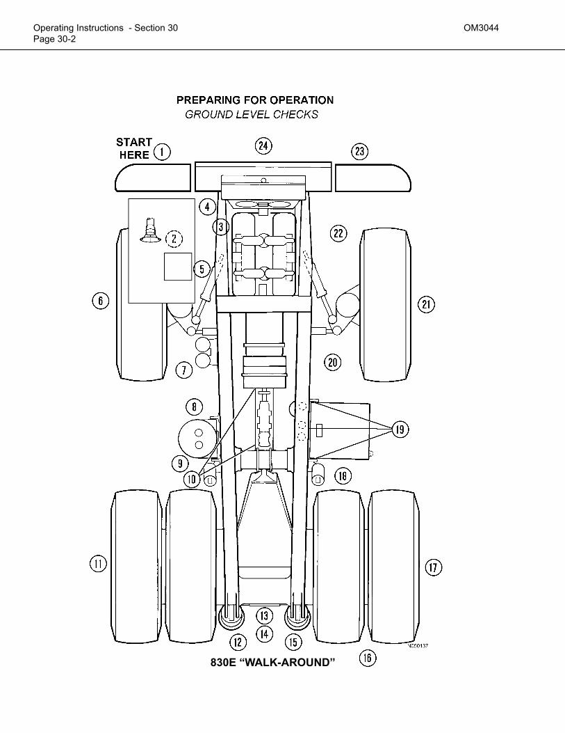
Operating Instructions - Section 30 OM3044Page 30-2
830E “WALK-AROUND”
OM3044 Operating Instructions - Section 30Page 30-3
9. Move on around the hydraulic tank and in front ofthe rear dual tires, inspect the hoist cylinder forany damage and leaks, also that lower guard is inplace. Inspect both upper and lower hoist cylinderpins for security, and for proper greasing.
10. Before leaving this position, look under the loweredge of the chassis to be sure the flexible ductthat carries the air from the main blower to thefinal drive housing is in good condition with noholes or breakage. Also look up at the mainhydraulic pumps to see that there is no leakage orany other unusual condition with pumps or pumpdrive shafts.
11. Move on around the dual tires, check to see thatall lugs/wedges are in place and tight. Inspectlatches on wheel cover to be sure they are prop-erly latched. Inspect wheel for any leakage thatmay be coming from inside the wheel cover thatwould indicate brake leakage, or wheel motorleakage.Check dual tires for cuts, damage or “bubbles”and that inflation appears to be correct. If truckhas been run on a “flat”, the tire must be cooledbefore parking truck inside. Inspect for any rocksthat might be lodged between dual tires, and thatrock ejector is in good condition and straight sothat it can not damage a tire.
12. Inspect left rear suspension for damage and forproper inflation, and that there are no leaks.Inspect also for proper greasing, and that coversover the chrome piston are in good condition.
13. Open rear hatch cover, turn ON work light, if nec-essary. Inspect for leaks around wheelmotormounting to rear housing, and also brake hosesand fittings. Be sure that covers on wheel motorsump are in place, and that there are no rags ortools left behind. Inspect condition of hatch covergasket, report any bad gasket to maintenance.Turn OFF work light if used, close and latchhatch.
14. While standing in front of rear hatch, look up tosee that rear lights are in good condition, alongwith dual back up horns. Look up at panhard rodto see that it is getting proper greasing. Also lookat both body hinge pins for greasing and anyabnormal condition. Check hoist limit switch.Remove any build-up of mud/debris.
15. Perform the same inspection on the right rear sus-pension as done on the left.
16. Move on around the right dual tires, inspectbetween the tires for rocks, and for condition ofthe rock ejector, inspect the tires for cuts or dam-age, and for correct inflation.
17. Perform the same inspection for wheel lugs/wedges, wheel cover latches, and for leaks thatwas done on the left hand dual wheels.
18. Move in front of right dual tires, and inspect thehoist cylinder the same as was done on the leftside.
19. Move on around the fuel tank, inspect the fuelquantity gauge (if equipped - this should agreewith the fuel gauge in the cab). Inspect the attach-ing hardware for the fuel tank at the upper sad-dles, and then at the lower back of the tank for thesecurity and condition of the resilient mounts.
20. Move in behind the right front wheel, and inspectthe steering cylinder, suspension attaching hard-ware and suspension extension, as well as greas-ing and attaching hardware for the steeringcylinder. Inspect the hub and brakes for leaks andany unusual condition. Be sure the suspensionprotective boot is in good condition.
21. Move out and around the right front wheel, inspectthat all lugs/wedges are in place and tight.
22. Move in behind the front of the right front wheel,check hub and brakes for leaks and any unusualcondition. Check hoist filters for leaks. Inspectsteering cylinder for security and for proper greas-ing. Inspect the engine compartment for any leaksand unusual condition. Inspect the fan guard, andbelts also for any rags or debris behind radiator.Turn work light OFF, if used, and secure the lad-der up and latched.
23. Move on around the front of the truck, drop the aircleaner pans to remove dirt, latch up and secure.
24. As you move in front of the radiator, inspect forany debris that might be stuck in front of the radia-tor and remove it. Check for any coolant leaks.Inspect all head and fog lights.
25. Before climbing ladder to first level, be sureground level engine shutdown switch is ON.Inspect fire control actuator to be sure safety pinis in place and plastic tie that prevents accidentalactuation is in place and in good condition.
26. Climb ladder to main deck. Always use grab railsand ladder when mounting or dismounting fromthe truck. Clean ladder and hand rails of any for-eign material, such as ice, snow, oil or mud.
Always mount and dismount ladders facing thetruck. Never attempt to mount or dismount whilethe truck is in motion.
Operating Instructions - Section 30 OM3044Page 30-4
27. Observe coolant level through opening in end ofhood. When checking coolant in radiator, relievepressure slowly before removing radiator cap.
If engine has been running, allow coolant to cool,before removing the fill cap or draining radiator.Serious burns may result if coolant is not allowedto cool.
28. Be sure battery disconnect switches are on.Inspect covers over retarding grids to be surelatches are in place and secure. Be sure batterybox hold down wing nuts are in place and secure.Inspect main air inlet to be sure it is clear. Be sureall cabinet door latches are secure.
29. Move on around the cab to the back, open thedoors to the brake cabinet, inspect for leaks.Before latching doors, turn work lights OFF, ifused.
30. Clean cab windows and mirrors; clean out cabfloor as necessary. Insure steering wheel, con-trols and pedals are free of any oil, grease ormud.
31. Stow personal gear in cab so that it does not inter-fere with any operation of the truck. Dirt or trashbuild-up, specifically in the operator's cab, shouldbe cleared. Do not carry tools or supplies in cab oftruck or on the deck.
32. Adjust seat and steering wheel so that it is com-fortable for use.
33. If the truck is in an enclosure, insure adequateventilation before start-up. Exhaust fumes aredangerous!
ENGINE START-UP SAFETY PRACTICES
NEVER ATTEMPT TO START THE ENGINE BYSHORTING ACROSS THE STARTER TERMINALS.This may cause fire, or serious injury or death toanyone in machine’s path.START THE ENGINE FROM THE OPERATOR’SSEAT ONLY.
1. Insure all personnel are clear of truck before start-ing engine. Always sound the horn as a warningbefore actuating any operational controls.
2. Check and insure Selector Switch is in NEUTRALposition and the park brake switch is in the ONposition before starting.
3. If truck is equipped with auxiliary cold weatherheater system(s);DO NOT attempt to start engine while heatersare in operation. DAMAGE TO COOLANTHEATERS WILL RESULT!
4. The keyswitch is a three position (OFF, RUN,START) switch. When switch is rotated one posi-tion clockwise, it is in the RUN position and allelectrical circuits (except START) are activated.With Selector Switch in NEUTRAL, rotate key-switch fully clockwise to START position and holdthis position until engine starts. START position isspring loaded to return to RUN when key isreleased. If the truck is equipped with a Komatsuengine, a time delay will occur before starterengagement and engine cranking begins. TheKomatsu engine is equipped with a Prelub™ Sys-tem that circulates engine oil throughout theengine prior to startup. The colder the engine oil,the longer the delay before cranking begins. Inaddition, if the engine is equipped with the EngineStarting Aid for cold weather starting, the EnginePrelub™ System should be engaged FIRST for 5to 10 seconds, or until the starters are engaged,BEFORE activating the Engine Starting Aid.
Starting fluid is extremely volatile and flammable!Use with extreme care.
If truck is equipped with optional Engine Starting Aidand ambient temperature is below 50°F (10°C), turnthe keyswitch to the START position, and while crank-ing engine, move the Engine Starting Aid switch to theON position for three (3) seconds MAXIMUM; thenrelease Engine Starting Aid. If engine does not start,wait at least fifteen (15) seconds before repeating theprocedure.
• Do not crank an electric starter for morethan 30 seconds.
• Allow two minutes for cooling beforeattempting to start engine again. Severe damage to starter motor can resultfrom overheating.
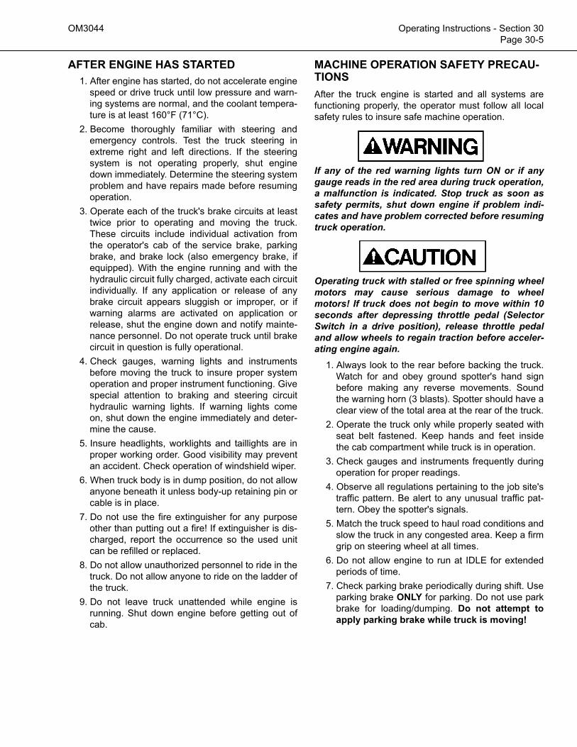
OM3044 Operating Instructions - Section 30Page 30-5
AFTER ENGINE HAS STARTED1. After engine has started, do not accelerate engine
speed or drive truck until low pressure and warn-ing systems are normal, and the coolant tempera-ture is at least 160°F (71°C).
2. Become thoroughly familiar with steering andemergency controls. Test the truck steering inextreme right and left directions. If the steeringsystem is not operating properly, shut enginedown immediately. Determine the steering systemproblem and have repairs made before resumingoperation.
3. Operate each of the truck's brake circuits at leasttwice prior to operating and moving the truck.These circuits include individual activation fromthe operator's cab of the service brake, parkingbrake, and brake lock (also emergency brake, ifequipped). With the engine running and with thehydraulic circuit fully charged, activate each circuitindividually. If any application or release of anybrake circuit appears sluggish or improper, or ifwarning alarms are activated on application orrelease, shut the engine down and notify mainte-nance personnel. Do not operate truck until brakecircuit in question is fully operational.
4. Check gauges, warning lights and instrumentsbefore moving the truck to insure proper systemoperation and proper instrument functioning. Givespecial attention to braking and steering circuithydraulic warning lights. If warning lights comeon, shut down the engine immediately and deter-mine the cause.
5. Insure headlights, worklights and taillights are inproper working order. Good visibility may preventan accident. Check operation of windshield wiper.
6. When truck body is in dump position, do not allowanyone beneath it unless body-up retaining pin orcable is in place.
7. Do not use the fire extinguisher for any purposeother than putting out a fire! If extinguisher is dis-charged, report the occurrence so the used unitcan be refilled or replaced.
8. Do not allow unauthorized personnel to ride in thetruck. Do not allow anyone to ride on the ladder ofthe truck.
9. Do not leave truck unattended while engine isrunning. Shut down engine before getting out ofcab.
MACHINE OPERATION SAFETY PRECAU-TIONSAfter the truck engine is started and all systems arefunctioning properly, the operator must follow all localsafety rules to insure safe machine operation.
If any of the red warning lights turn ON or if anygauge reads in the red area during truck operation,a malfunction is indicated. Stop truck as soon assafety permits, shut down engine if problem indi-cates and have problem corrected before resumingtruck operation.
Operating truck with stalled or free spinning wheelmotors may cause serious damage to wheelmotors! If truck does not begin to move within 10seconds after depressing throttle pedal (SelectorSwitch in a drive position), release throttle pedaland allow wheels to regain traction before acceler-ating engine again.
1. Always look to the rear before backing the truck.Watch for and obey ground spotter's hand signbefore making any reverse movements. Soundthe warning horn (3 blasts). Spotter should have aclear view of the total area at the rear of the truck.
2. Operate the truck only while properly seated withseat belt fastened. Keep hands and feet insidethe cab compartment while truck is in operation.
3. Check gauges and instruments frequently duringoperation for proper readings.
4. Observe all regulations pertaining to the job site'straffic pattern. Be alert to any unusual traffic pat-tern. Obey the spotter's signals.
5. Match the truck speed to haul road conditions andslow the truck in any congested area. Keep a firmgrip on steering wheel at all times.
6. Do not allow engine to run at IDLE for extendedperiods of time.
7. Check parking brake periodically during shift. Useparking brake ONLY for parking. Do not use parkbrake for loading/dumping. Do not attempt toapply parking brake while truck is moving!
Operating Instructions - Section 30 OM3044Page 30-6
Do not use “Brake Lock” or “Emergency Brake” (ifequipped) for parking.
8. Check brake lock performance periodically forsafe loading and dump operation.
9. Proceed slowly on rough terrain to avoid deepruts or large obstacles. Avoid traveling close tosoft edges and the edge of fill area.
10. Truck operation requires concentrated effort bythe driver. Avoid distractions of any kind whileoperating the truck.
LOADING1. Pull into the loading area with caution. Remain at
a safe distance while truck ahead is being loaded.2. Do not drive over unprotected power cables.3. When approaching or leaving a loading area,
watch out for other vehicles and for personnelworking in the area.
4. When pulling in under a loader or shovel, follow“Spotter” or “Shovel Operator” signals. The truckoperator may speed up loading operations byobserving the location and loading cycle of thetruck being loaded ahead, then follow a similarpattern.
5. When being loaded, operator should stay in truckcab. Place Selector Switch in NEUTRAL andapply brake lock with engine running.
6. When loaded, pull away from shovel as quickly aspossible but with extreme caution.
HAULING1. Always stay alert! If unfamiliar with the road, drive
with extreme caution. Cab doors should remainclosed at all times if truck is in motion or unat-tended.
2. Obey all road signs. Operate truck so it is undercontrol at all times. Govern truck speed by theroad conditions, weather and visibility. Reporthaul road conditions immediately. Muddy or icyroads, pot holes or other obstructions can presenthazards.
3. When backing the truck, give backup signal (threeblasts on the horn); when starting forward, twoblasts on the horn. These signals must be giveneach time the truck is moved forward or back-ward.
4. Use extreme caution when approaching a haulroad intersection. Maintain a safe distance fromoncoming vehicles.
5. Maintain a safe distance when following anothervehicle. Never approach another vehicle from therear, in the same lane, closer than 50 ft. (15 m).When driving on a down grade, this distanceshould not be less than 100 ft. (30 m).
6. Do not stop or park on a haul road unlessunavoidable. If you must stop, move truck to asafe place, apply parking brake, block wheelssecurely, shut down engine and notify mainte-nance personnel for assistance.
7. Before starting up or down a grade, maintain aspeed that will insure safe driving and provideeffective retarding under all conditions. Refer toGrade/Speed decal in operator's cab.
8. When operating truck in darkness, or when visibil-ity is poor, do not move truck unless headlightsare on. Do not back truck if backup horn or lightsare inoperative. Always dim headlights whenmeeting oncoming vehicles.
9. If the Emergency Steering light and/or Low BrakePressure Warning light (if equipped) illuminateduring operation, steer the truck immediately to asafe stopping area, away from other traffic, if pos-sible. Refer to item 6 above.
10. The Statex III system monitors wheel motor,ambient, and static exciter temperatures. If wheelmotor or static exciter temperature is outside thelimits established, the Statex III controls will causethe engine to increase to 1650 RPM. (Normalengine RPM for haul road/retarding operation is1250 RPM.)
11. When maximum truck speed is reached, the truckwill experience a DECREASE in engine RPM.
12. Check tires for proper inflation periodically duringshift. If truck has been run on a flat”, or under-inflated tire, it must not be parked in a buildinguntil the tire cools.
PASSING1. Do not pass another truck on a hill or blind curve!2. Before passing, make sure the road ahead is
clear. If a disabled truck is blocking your lane,slow down and pass with extreme caution.
3. Use only the areas designated for passing.
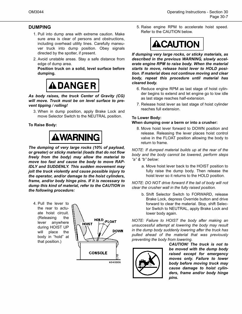
OM3044 Operating Instructions - Section 30Page 30-7
DUMPING1. Pull into dump area with extreme caution. Make
sure area is clear of persons and obstructions,including overhead utility lines. Carefully maneu-ver truck into dump position. Obey signalsdirected by the spotter, if present.
2. Avoid unstable areas. Stay a safe distance fromedge of dump area. Position truck on a solid, level surface beforedumping.
As body raises, the truck Center of Gravity (CG)will move. Truck must be on level surface to pre-vent tipping / rolling!
3. When in dump position, apply Brake Lock andmove Selector Switch to the NEUTRAL position.
To Raise Body:
The dumping of very large rocks (10% of payload,or greater) or sticky material (loads that do not flowfreely from the body) may allow the material tomove too fast and cause the body to move RAP-IDLY and SUDDENLY. This sudden movement mayjolt the truck violently and cause possible injury tothe operator, and/or damage to the hoist cylinders,frame, and/or body hinge pins. If it is necessary todump this kind of material, refer to the CAUTION inthe following procedure:
4. Pull the lever tothe rear to actu-ate hoist circuit.(Releasing thelever anywhereduring HOIST UPwill place thebody in “hold” atthat position.)
5. Raise engine RPM to accelerate hoist speed.Refer to the CAUTION below.
If dumping very large rocks, or sticky materials, asdescribed in the previous WARNING, slowly accel-erate engine RPM to raise body. When the materialstarts to move, release hoist lever to HOLD posi-tion. If material does not continue moving and clearbody, repeat this procedure until material hascleared body.
6. Reduce engine RPM as last stage of hoist cylin-der begins to extend and let engine go to low idleas last stage reaches half-extension.
7. Release hoist lever as last stage of hoist cylinderreaches full extension.
To Lower Body:When dumping over a berm or into a crusher:
8. Move hoist lever forward to DOWN position andrelease. Releasing the lever places hoist controlvalve in the FLOAT position allowing the body toreturn to frame.
NOTE: If dumped material builds up at the rear of thebody and the body cannot be lowered, perform steps“a” & “b” below:
a. Move hoist lever back to the HOIST position tofully raise the dump body. Then release thehoist lever so it returns to the HOLD position.
NOTE: DO NOT drive forward if the tail of body will notclear the crusher wall in the fully raised position.
b. Shift Selector Switch to FORWARD, releaseBrake Lock, depress Override button and driveforward to clear the material. Stop, shift Selec-tor Switch to NEUTRAL, apply Brake Lock andlower body again.
NOTE: Failure to HOIST the body after making anunsuccessful attempt at lowering the body may resultin the dump body suddenly lowering after the truck haspulled ahead of the material that was previouslypreventing the body from lowering.
CAUTION! The truck is not tobe moved with the dump bodyraised except for emergencymoves only. Failure to lowerbody before moving truck maycause damage to hoist cylin-ders, frame and/or body hingepins.
Operating Instructions - Section 30 OM3044Page 30-8
To Lower Body:When dumping on flat ground:
It is very likely when dumping on flat ground that thedumped material will build up enough to prevent thebody from lowering. In this case, the truck will have tobe driven forward a short distance (just enough to clearthe material) before the body can be lowered.
a. Shift Selector Switch to FORWARD, releaseBrake Lock, depress Override button and drivejust far enough forward for body to clear mate-rial. Stop, shift Selector Switch to NEUTRAL,apply Brake Lock.
b. Move hoist lever forward to DOWN positionand release. Releasing the lever places hoistcontrol valve in the FLOAT position allowingthe body to return to frame.
NOTE: If dumped material builds up at the rear of thebody and the body cannot be lowered, then performsteps “c” and “d” below:
c. Move hoist lever back to the HOIST position tofully raise the dump body. Then release thehoist lever so it returns to the HOLD position.
d. Shift Selector Switch to FORWARD, releaseBrake Lock, depress Override button and driveforward to clear the material. Stop, shift Selec-tor Switch to NEUTRAL, apply Brake Lock andlower body again.
NOTE: Failure to “hoist” the body after making anunsuccessful attempt at lowering the body may resultin the dump body suddenly lowering after the truck haspulled ahead of the material that was previouslypreventing the body from lowering.
CAUTION! The truck is notto be moved with the dumpbody raised except foremergency moves only.Failure to lower bodybefore moving truck maycause damage to hoist cyl-inders, frame and/or bodyhinge pins.
9. With body returned to frame, move SelectorSwitch to FORWARD, release Brake Lock, andleave dump area carefully.
TOWINGPrior to towing a truck, many factors must be carefullyconsidered. Serious personal injury and/or significantproperty damage may result if important safety prac-tices, procedures and preparation for moving heavyequipment are not observed.Do not tow the truck faster than 5 MPH (8 KPH).
A disabled machine may be towed after the followingMINIMUM precautions have been taken.
1. Shut down engine.2. Chock wheels on disabled truck to prevent move-
ment while attaching tow bar.3. If truck is equipped, install hydraulic connections
for steering/braking and dumping between towingand towed vehicles. Check towed vehicle for nor-mal braking and steering system operation.
4. Empty all material from dump body of truck that isto be towed.
5. Inspect tow bar for adequacy (approximately 1.5times the gross vehicle weight of truck beingtowed).
6. Determine that towing vehicle has adequatecapacity to both move and stop the towed truckunder all conditions.
7. Protect both operators in the event of tow bar fail-ure.
8. Release disabled truck brakes and remove block-ing.
9. Sudden movement may cause tow bar failure.Smooth and gradual truck movement is preferred.
10. Minimize tow angle at all times - NEVER EXCEED30°. The towed truck must be steered in the directionof the tow bar.
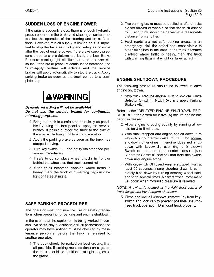
OM3044 Operating Instructions - Section 30Page 30-9
SUDDEN LOSS OF ENGINE POWERIf the engine suddenly stops, there is enough hydraulicpressure stored in the brake and steering accumulatorsto allow the operation of the steering and brake func-tions. However, this oil supply is limited so it is impor-tant to stop the truck as quickly and safely as possibleafter the loss of engine power. If the brake supply pres-sure drops to a pre-determined level, the Low BrakePressure warning light will illuminate and a buzzer willsound. If the brake pressure continues to decrease, the“Auto-Apply” feature will activate and the servicebrakes will apply automatically to stop the truck. Applyparking brake as soon as the truck comes to a com-plete stop.
Dynamic retarding will not be available!Do not use the service brakes for continuousretarding purposes.
1. Bring the truck to a safe stop as quickly as possi-ble by using the foot pedal to apply the servicebrakes. If possible, steer the truck to the side ofthe road while bringing it to a complete stop.
2. Apply the parking brake as soon as the truck hasstopped moving.
3. Turn key switch OFF and notify maintenance per-sonnel immediately.
4. If safe to do so, place wheel chocks in front orbehind the wheels so that truck cannot roll.
5. If the truck becomes disabled where traffic isheavy, mark the truck with warning flags in day-light or flares at night.
SAFE PARKING PROCEDURESThe operator must continue the use of safety precau-tions when preparing for parking and engine shutdown.
In the event that the equipment is being worked in con-secutive shifts, any questionable truck performance theoperator may have noticed must be checked by main-tenance personnel before the truck is released toanother operator.
1. The truck should be parked on level ground, if atall possible. If parking must be done on a grade,the truck should be positioned at right angles tothe grade.
2. The parking brake must be applied and/or chocksplaced fore/aft of wheels so that the truck cannotroll. Each truck should be parked at a reasonabledistance from another.
3. Haul roads are not safe parking areas. In anemergency, pick the safest spot most visible toother machines in the area. If the truck becomesdisabled where traffic is heavy, mark the truckwith warning flags in daylight or flares at night.
ENGINE SHUTDOWN PROCEDUREThe following procedure should be followed at eachengine shutdown.
1. Stop truck. Reduce engine RPM to low idle. PlaceSelector Switch in NEUTRAL and apply ParkingBrake switch.
Refer to the “DELAYED ENGINE SHUTDOWN PRO-CEDURE” if the option for a five (5) minute engine idleperiod is desired.
2. Allow engine to cool gradually by running at lowidle for 3 to 5 minutes.
3. With truck stopped and engine cooled down, turnkeyswitch counterclockwise to OFF for normalshutdown of engines. If engine does not shut-down with keyswitch, use Engine ShutdownSwitch on the operator's center console (see“Operator Controls” section) and hold this switchdown until engine stops.
4. With keyswitch OFF, and engine stopped, wait atleast 90 seconds. Insure steering circuit is com-pletely bled down by turning steering wheel backand forth several times. No front wheel movementwill occur when hydraulic pressure is relieved.
NOTE: A switch is located at the right front corner oftruck for ground level engine shutdown.
5. Close and lock all windows, remove key from key-switch and lock cab to prevent possible unautho-rized truck operation. Dismount truck properly.
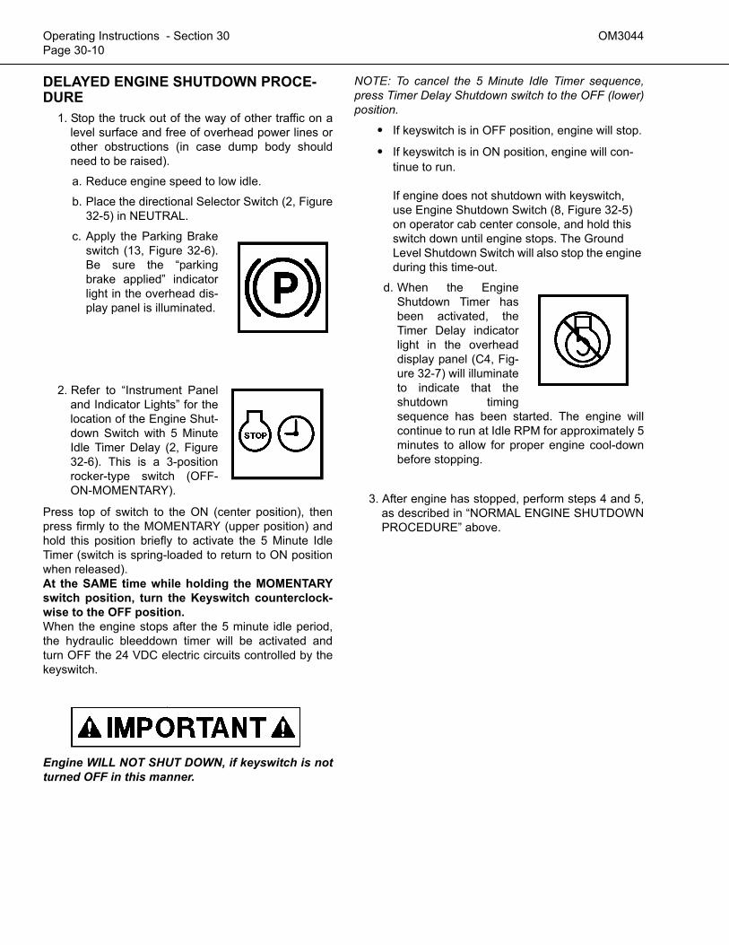
Operating Instructions - Section 30 OM3044Page 30-10
DELAYED ENGINE SHUTDOWN PROCE-DURE
1. Stop the truck out of the way of other traffic on alevel surface and free of overhead power lines orother obstructions (in case dump body shouldneed to be raised).
a. Reduce engine speed to low idle.
b. Place the directional Selector Switch (2, Figure32-5) in NEUTRAL.
c. Apply the Parking Brakeswitch (13, Figure 32-6).Be sure the “parkingbrake applied” indicatorlight in the overhead dis-play panel is illuminated.
2. Refer to “Instrument Paneland Indicator Lights” for thelocation of the Engine Shut-down Switch with 5 MinuteIdle Timer Delay (2, Figure32-6). This is a 3-positionrocker-type switch (OFF-ON-MOMENTARY).
Press top of switch to the ON (center position), thenpress firmly to the MOMENTARY (upper position) andhold this position briefly to activate the 5 Minute IdleTimer (switch is spring-loaded to return to ON positionwhen released).At the SAME time while holding the MOMENTARYswitch position, turn the Keyswitch counterclock-wise to the OFF position. When the engine stops after the 5 minute idle period,the hydraulic bleeddown timer will be activated andturn OFF the 24 VDC electric circuits controlled by thekeyswitch.
Engine WILL NOT SHUT DOWN, if keyswitch is notturned OFF in this manner.
NOTE: To cancel the 5 Minute Idle Timer sequence,press Timer Delay Shutdown switch to the OFF (lower)position.
• If keyswitch is in OFF position, engine will stop.
• If keyswitch is in ON position, engine will con-tinue to run.
If engine does not shutdown with keyswitch, use Engine Shutdown Switch (8, Figure 32-5) on operator cab center console, and hold this switch down until engine stops. The Ground Level Shutdown Switch will also stop the engine during this time-out.
d. When the EngineShutdown Timer hasbeen activated, theTimer Delay indicatorlight in the overheaddisplay panel (C4, Fig-ure 32-7) will illuminateto indicate that theshutdown timingsequence has been started. The engine willcontinue to run at Idle RPM for approximately 5minutes to allow for proper engine cool-downbefore stopping.
3. After engine has stopped, perform steps 4 and 5,as described in “NORMAL ENGINE SHUTDOWNPROCEDURE” above.
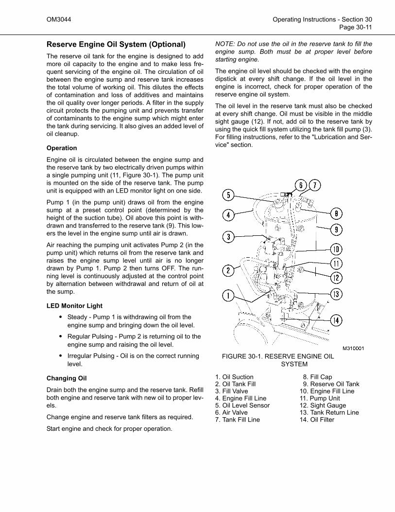
OM3044 Operating Instructions - Section 30Page 30-11
Reserve Engine Oil System (Optional)The reserve oil tank for the engine is designed to addmore oil capacity to the engine and to make less fre-quent servicing of the engine oil. The circulation of oilbetween the engine sump and reserve tank increasesthe total volume of working oil. This dilutes the effectsof contamination and loss of additives and maintainsthe oil quality over longer periods. A filter in the supplycircuit protects the pumping unit and prevents transferof contaminants to the engine sump which might enterthe tank during servicing. It also gives an added level ofoil cleanup.
Operation
Engine oil is circulated between the engine sump andthe reserve tank by two electrically driven pumps withina single pumping unit (11, Figure 30-1). The pump unitis mounted on the side of the reserve tank. The pumpunit is equipped with an LED monitor light on one side.
Pump 1 (in the pump unit) draws oil from the enginesump at a preset control point (determined by theheight of the suction tube). Oil above this point is with-drawn and transferred to the reserve tank (9). This low-ers the level in the engine sump until air is drawn.
Air reaching the pumping unit activates Pump 2 (in thepump unit) which returns oil from the reserve tank andraises the engine sump level until air is no longerdrawn by Pump 1. Pump 2 then turns OFF. The run-ning level is continuously adjusted at the control pointby alternation between withdrawal and return of oil atthe sump.
LED Monitor Light• Steady - Pump 1 is withdrawing oil from the
engine sump and bringing down the oil level.
• Regular Pulsing - Pump 2 is returning oil to the engine sump and raising the oil level.
• Irregular Pulsing - Oil is on the correct running level.
Changing Oil
Drain both the engine sump and the reserve tank. Refillboth engine and reserve tank with new oil to proper lev-els.
Change engine and reserve tank filters as required.
Start engine and check for proper operation.
NOTE: Do not use the oil in the reserve tank to fill theengine sump. Both must be at proper level beforestarting engine.
The engine oil level should be checked with the enginedipstick at every shift change. If the oil level in theengine is incorrect, check for proper operation of thereserve engine oil system.
The oil level in the reserve tank must also be checkedat every shift change. Oil must be visible in the middlesight gauge (12). If not, add oil to the reserve tank byusing the quick fill system utilizing the tank fill pump (3).For filling instructions, refer to the "Lubrication and Ser-vice" section.
1. Oil Suction2. Oil Tank Fill3. Fill Valve4. Engine Fill Line5. Oil Level Sensor6. Air Valve7. Tank Fill Line
8. Fill Cap 9. Reserve Oil Tank10. Engine Fill Line11. Pump Unit12. Sight Gauge13. Tank Return Line14. Oil Filter
FIGURE 30-1. RESERVE ENGINE OIL SYSTEM

Operating Instructions - Section 30 OM3044Page 30-12
NOTES:
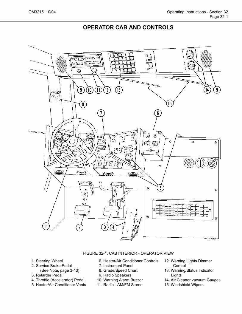
OM3215 10/04 Operating Instructions - Section 32Page 32-1
OPERATOR CAB AND CONTROLS
FIGURE 32-1. CAB INTERIOR - OPERATOR VIEW
1. Steering Wheel2. Service Brake Pedal
(See Note, page 3-13)3. Retarder Pedal4. Throttle (Accelerator) Pedal5. Heater/Air Conditioner Vents
6. Heater/Air Conditioner Controls7. Instrument Panel8. Grade/Speed Chart9. Radio Speakers
10. Warning Alarm Buzzer11. Radio - AM/FM Stereo
12. Warning Lights Dimmer Control
13. Warning/Status IndicatorLights
14. Air Cleaner vacuum Gauges15. Windshield Wipers
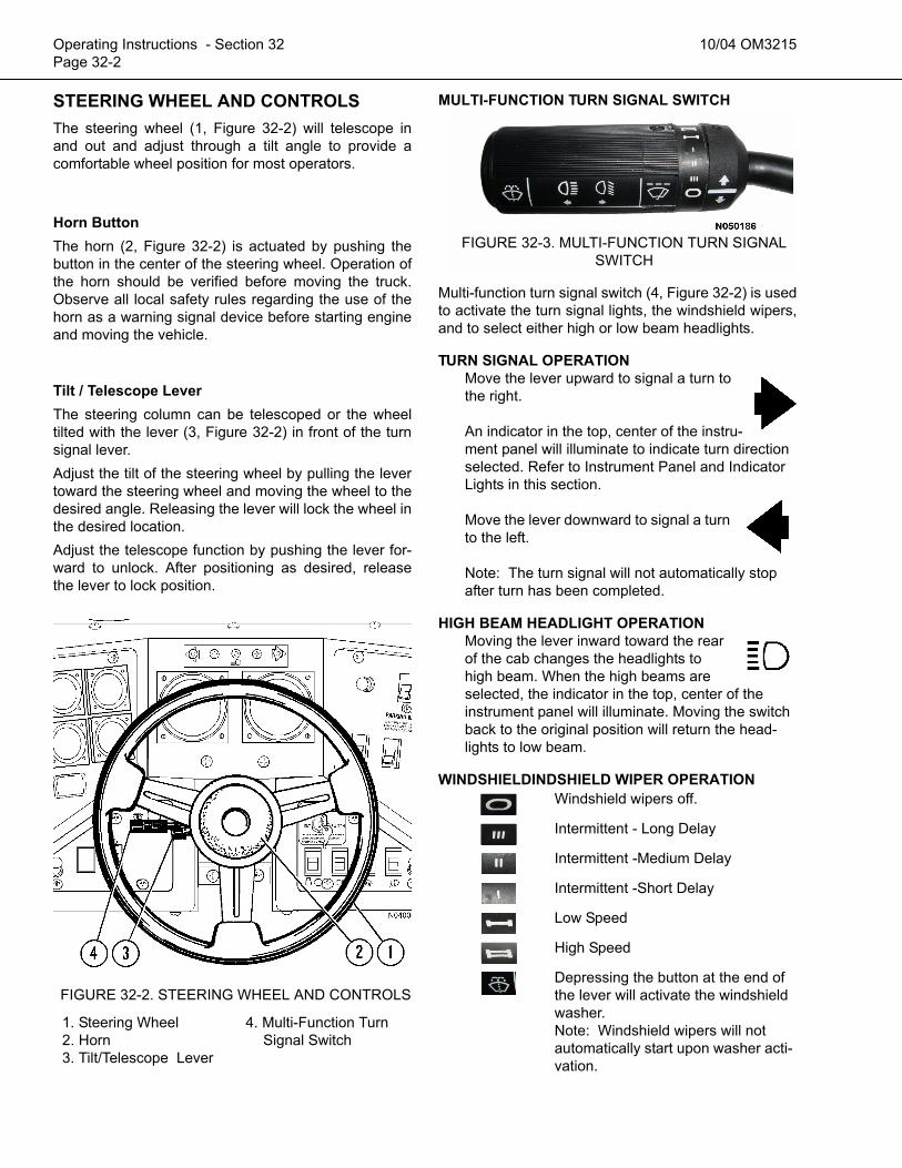
Operating Instructions - Section 32 10/04 OM3215Page 32-2
STEERING WHEEL AND CONTROLSThe steering wheel (1, Figure 32-2) will telescope inand out and adjust through a tilt angle to provide acomfortable wheel position for most operators.
Horn ButtonThe horn (2, Figure 32-2) is actuated by pushing thebutton in the center of the steering wheel. Operation ofthe horn should be verified before moving the truck.Observe all local safety rules regarding the use of thehorn as a warning signal device before starting engineand moving the vehicle.
Tilt / Telescope LeverThe steering column can be telescoped or the wheeltilted with the lever (3, Figure 32-2) in front of the turnsignal lever.Adjust the tilt of the steering wheel by pulling the levertoward the steering wheel and moving the wheel to thedesired angle. Releasing the lever will lock the wheel inthe desired location.Adjust the telescope function by pushing the lever for-ward to unlock. After positioning as desired, releasethe lever to lock position.
MULTI-FUNCTION TURN SIGNAL SWITCH
Multi-function turn signal switch (4, Figure 32-2) is usedto activate the turn signal lights, the windshield wipers,and to select either high or low beam headlights.
TURN SIGNAL OPERATIONMove the lever upward to signal a turn to the right.
An indicator in the top, center of the instru-ment panel will illuminate to indicate turn direction selected. Refer to Instrument Panel and Indicator Lights in this section.
Move the lever downward to signal a turn to the left.
Note: The turn signal will not automatically stop after turn has been completed.
HIGH BEAM HEADLIGHT OPERATIONMoving the lever inward toward the rear of the cab changes the headlights to high beam. When the high beams are selected, the indicator in the top, center of the instrument panel will illuminate. Moving the switch back to the original position will return the head-lights to low beam.
WINDSHIELDINDSHIELD WIPER OPERATION
FIGURE 32-2. STEERING WHEEL AND CONTROLS
1. Steering Wheel2. Horn3. Tilt/Telescope Lever
4. Multi-Function Turn Signal Switch
Windshield wipers off.
Intermittent - Long Delay
Intermittent -Medium Delay
Intermittent -Short Delay
Low Speed
High Speed
Depressing the button at the end of the lever will activate the windshield washer.Note: Windshield wipers will not automatically start upon washer acti-vation.
FIGURE 32-3. MULTI-FUNCTION TURN SIGNAL SWITCH
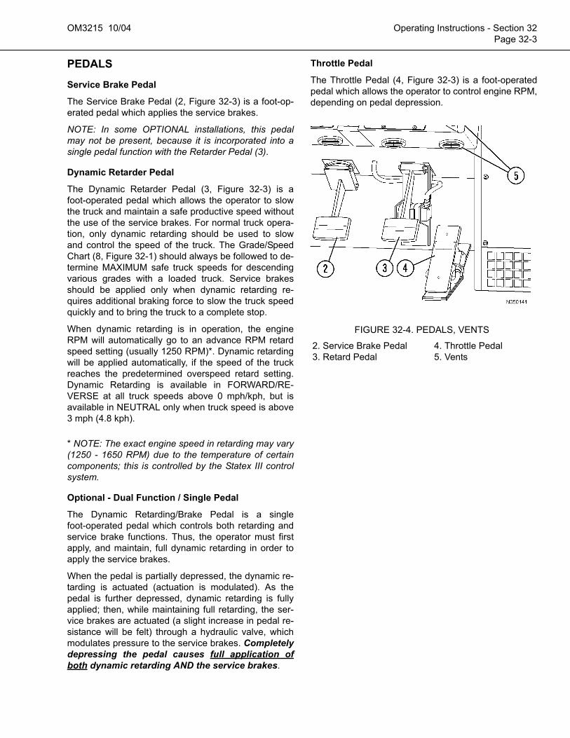
OM3215 10/04 Operating Instructions - Section 32Page 32-3
PEDALS
Service Brake Pedal
The Service Brake Pedal (2, Figure 32-3) is a foot-op-erated pedal which applies the service brakes.
NOTE: In some OPTIONAL installations, this pedalmay not be present, because it is incorporated into asingle pedal function with the Retarder Pedal (3).
Dynamic Retarder Pedal
The Dynamic Retarder Pedal (3, Figure 32-3) is afoot-operated pedal which allows the operator to slowthe truck and maintain a safe productive speed withoutthe use of the service brakes. For normal truck opera-tion, only dynamic retarding should be used to slowand control the speed of the truck. The Grade/SpeedChart (8, Figure 32-1) should always be followed to de-termine MAXIMUM safe truck speeds for descendingvarious grades with a loaded truck. Service brakesshould be applied only when dynamic retarding re-quires additional braking force to slow the truck speedquickly and to bring the truck to a complete stop.
When dynamic retarding is in operation, the engineRPM will automatically go to an advance RPM retardspeed setting (usually 1250 RPM)*. Dynamic retardingwill be applied automatically, if the speed of the truckreaches the predetermined overspeed retard setting.Dynamic Retarding is available in FORWARD/RE-VERSE at all truck speeds above 0 mph/kph, but isavailable in NEUTRAL only when truck speed is above3 mph (4.8 kph).
* NOTE: The exact engine speed in retarding may vary(1250 - 1650 RPM) due to the temperature of certaincomponents; this is controlled by the Statex III controlsystem.
Optional - Dual Function / Single Pedal
The Dynamic Retarding/Brake Pedal is a singlefoot-operated pedal which controls both retarding andservice brake functions. Thus, the operator must firstapply, and maintain, full dynamic retarding in order toapply the service brakes.
When the pedal is partially depressed, the dynamic re-tarding is actuated (actuation is modulated). As thepedal is further depressed, dynamic retarding is fullyapplied; then, while maintaining full retarding, the ser-vice brakes are actuated (a slight increase in pedal re-sistance will be felt) through a hydraulic valve, whichmodulates pressure to the service brakes. Completelydepressing the pedal causes full application ofboth dynamic retarding AND the service brakes.
Throttle Pedal
The Throttle Pedal (4, Figure 32-3) is a foot-operatedpedal which allows the operator to control engine RPM,depending on pedal depression.
2. Service Brake Pedal3. Retard Pedal
4. Throttle Pedal5. Vents
FIGURE 32-4. PEDALS, VENTS
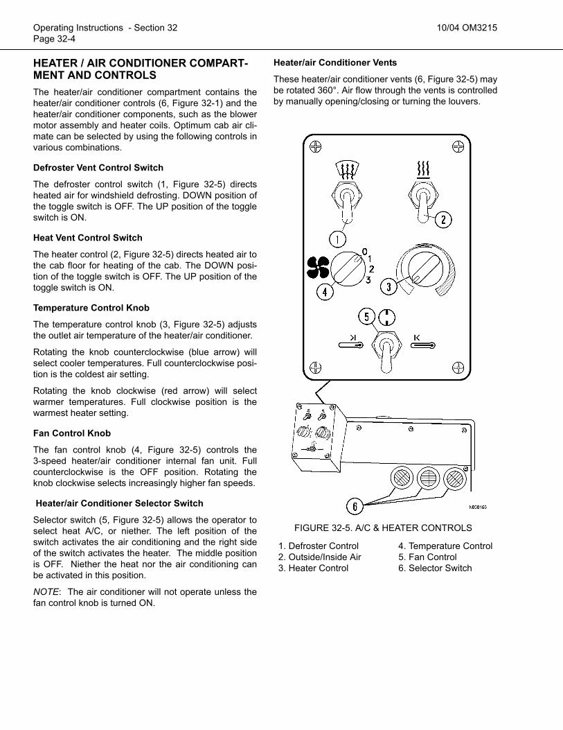
Operating Instructions - Section 32 10/04 OM3215Page 32-4
HEATER / AIR CONDITIONER COMPART-MENT AND CONTROLSThe heater/air conditioner compartment contains theheater/air conditioner controls (6, Figure 32-1) and theheater/air conditioner components, such as the blowermotor assembly and heater coils. Optimum cab air cli-mate can be selected by using the following controls invarious combinations.
Defroster Vent Control Switch
The defroster control switch (1, Figure 32-5) directsheated air for windshield defrosting. DOWN position ofthe toggle switch is OFF. The UP position of the toggleswitch is ON.
Heat Vent Control Switch
The heater control (2, Figure 32-5) directs heated air tothe cab floor for heating of the cab. The DOWN posi-tion of the toggle switch is OFF. The UP position of thetoggle switch is ON.
Temperature Control Knob
The temperature control knob (3, Figure 32-5) adjuststhe outlet air temperature of the heater/air conditioner.
Rotating the knob counterclockwise (blue arrow) willselect cooler temperatures. Full counterclockwise posi-tion is the coldest air setting.
Rotating the knob clockwise (red arrow) will selectwarmer temperatures. Full clockwise position is thewarmest heater setting.
Fan Control Knob
The fan control knob (4, Figure 32-5) controls the3-speed heater/air conditioner internal fan unit. Fullcounterclockwise is the OFF position. Rotating theknob clockwise selects increasingly higher fan speeds.
Heater/air Conditioner Selector Switch
Selector switch (5, Figure 32-5) allows the operator toselect heat A/C, or niether. The left position of theswitch activates the air conditioning and the right sideof the switch activates the heater. The middle positionis OFF. Niether the heat nor the air conditioning canbe activated in this position.
NOTE: The air conditioner will not operate unless thefan control knob is turned ON.
Heater/air Conditioner Vents
These heater/air conditioner vents (6, Figure 32-5) maybe rotated 360°. Air flow through the vents is controlledby manually opening/closing or turning the louvers.
FIGURE 32-5. A/C & HEATER CONTROLS
1. Defroster Control2. Outside/Inside Air3. Heater Control
4. Temperature Control5. Fan Control6. Selector Switch
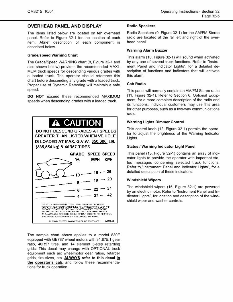
OM3215 10/04 Operating Instructions - Section 32Page 32-5
OVERHEAD PANEL AND DISPLAYThe items listed below are located on teh overheadpanel. Refer to Figure 32-1 for the location of eachitem. Abrief description of each component isdescribed below.
Grade/speed Warning Chart
The Grade/Speed WARNING chart (8, Figure 32-1 andalso shown below) provides the recommended MAXI-MUM truck speeds for descending various grades witha loaded truck. The operator should reference thischart before descending any grade with a loaded truck.Proper use of Dynamic Retarding will maintain a safespeed.
DO NOT exceed these recommended MAXIMUMspeeds when descending grades with a loaded truck.
The sample chart above applies to a model 830Eequipped with GE787 wheel motors with 31.875:1 gearratio, 40R57 tires, and 14 element 3-step retardinggrids. This decal may change with OPTIONAL truckequipment such as: wheelmotor gear ratios, retardergrids, tire sizes, etc. ALWAYS refer to this decal inthe operator's cab, and follow these recommenda-tions for truck operation.
Radio Speakers
Radio Speakers (9, Figure 32-1) for the AM/FM Stereoradio are located at the far left and right of the over-head panel.
Warning Alarm Buzzer
This alarm (10, Figure 32-1) will sound when activatedby any one of several truck functions. Refer to ”Instru-ment Panel and Indicator Lights”, for a detailed de-scription of functions and indicators that will activatethis alarm.
Cab Radio
This panel will normally contain an AM/FM Stereo radio(11, Figure 32-1). Refer to Section 6, Optional Equip-ment, for a more complete description of the radio andits functions. Individual customers may use this areafor other purposes, such as a two-way communicationsradio.
Warning Lights Dimmer Control
This control knob (12, Figure 32-1) permits the opera-tor to adjust the brightness of the Warning IndicatorLights.
Status / Warning Indicator Light Panel
This panel (13, Figure 32-1) contains an array of indi-cator lights to provide the operator with important sta-tus messages concerning selected truck functions.Refer to “Instrument Panel and Indicator Lights”, for adetailed description of these indicators.
Windshield Wipers
The windshield wipers (15, Figure 32-1) are poweredby an electric motor. Refer to “Instrument Panel and In-dicator Lights”, for location and description of the wind-shield wiper and washer controls.
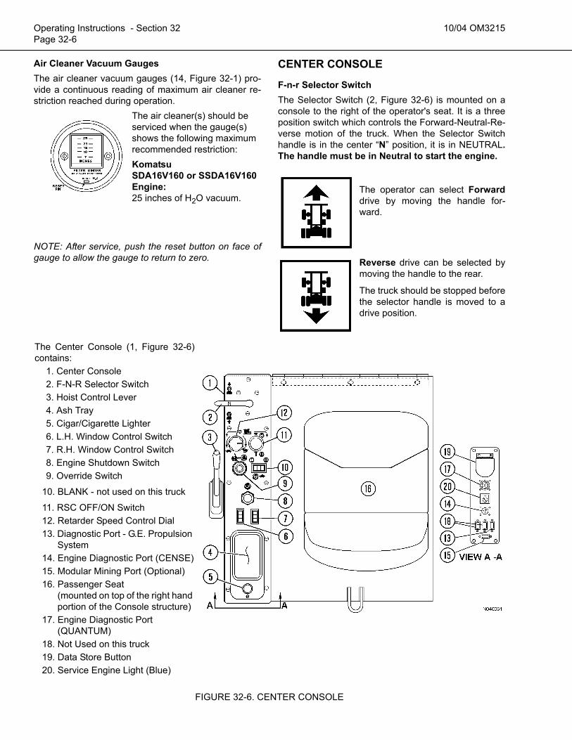
Operating Instructions - Section 32 10/04 OM3215Page 32-6
Air Cleaner Vacuum GaugesThe air cleaner vacuum gauges (14, Figure 32-1) pro-vide a continuous reading of maximum air cleaner re-striction reached during operation.
The air cleaner(s) should be serviced when the gauge(s) shows the following maximum recommended restriction:Komatsu SDA16V160 or SSDA16V160 Engine: 25 inches of H2O vacuum.
NOTE: After service, push the reset button on face ofgauge to allow the gauge to return to zero.
CENTER CONSOLE
F-n-r Selector Switch The Selector Switch (2, Figure 32-6) is mounted on aconsole to the right of the operator's seat. It is a threeposition switch which controls the Forward-Neutral-Re-verse motion of the truck. When the Selector Switchhandle is in the center “N” position, it is in NEUTRAL.The handle must be in Neutral to start the engine.
The operator can select Forwarddrive by moving the handle for-ward.
Reverse drive can be selected bymoving the handle to the rear.
The truck should be stopped beforethe selector handle is moved to adrive position.
FIGURE 32-6. CENTER CONSOLE
The Center Console (1, Figure 32-6)contains:
1. Center Console2. F-N-R Selector Switch3. Hoist Control Lever 4. Ash Tray5. Cigar/Cigarette Lighter6. L.H. Window Control Switch7. R.H. Window Control Switch8. Engine Shutdown Switch9. Override Switch
10. BLANK - not used on this truck
11. RSC OFF/ON Switch 12. Retarder Speed Control Dial 13. Diagnostic Port - G.E. Propulsion
System 14. Engine Diagnostic Port (CENSE)15. Modular Mining Port (Optional)16. Passenger Seat
(mounted on top of the right hand portion of the Console structure)
17. Engine Diagnostic Port (QUANTUM)
18. Not Used on this truck19. Data Store Button20. Service Engine Light (Blue)
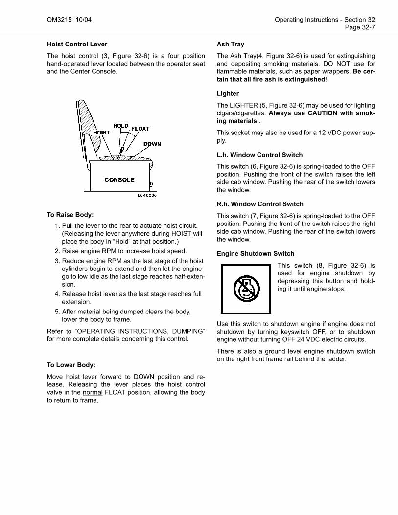
OM3215 10/04 Operating Instructions - Section 32Page 32-7
Hoist Control Lever
The hoist control (3, Figure 32-6) is a four positionhand-operated lever located between the operator seatand the Center Console.
To Raise Body: 1. Pull the lever to the rear to actuate hoist circuit.
(Releasing the lever anywhere during HOIST will place the body in “Hold” at that position.)
2. Raise engine RPM to increase hoist speed. 3. Reduce engine RPM as the last stage of the hoist
cylinders begin to extend and then let the engine go to low idle as the last stage reaches half-exten-sion.
4. Release hoist lever as the last stage reaches full extension.
5. After material being dumped clears the body, lower the body to frame.
Refer to “OPERATING INSTRUCTIONS, DUMPING”for more complete details concerning this control.
To Lower Body:
Move hoist lever forward to DOWN position and re-lease. Releasing the lever places the hoist controlvalve in the normal FLOAT position, allowing the bodyto return to frame.
Ash Tray
The Ash Tray(4, Figure 32-6) is used for extinguishingand depositing smoking materials. DO NOT use forflammable materials, such as paper wrappers. Be cer-tain that all fire ash is extinguished!
Lighter
The LIGHTER (5, Figure 32-6) may be used for lightingcigars/cigarettes. Always use CAUTION with smok-ing materials!.
This socket may also be used for a 12 VDC power sup-ply.
L.h. Window Control Switch
This switch (6, Figure 32-6) is spring-loaded to the OFFposition. Pushing the front of the switch raises the leftside cab window. Pushing the rear of the switch lowersthe window.
R.h. Window Control Switch
This switch (7, Figure 32-6) is spring-loaded to the OFFposition. Pushing the front of the switch raises the rightside cab window. Pushing the rear of the switch lowersthe window.
Engine Shutdown Switch
This switch (8, Figure 32-6) isused for engine shutdown bydepressing this button and hold-ing it until engine stops.
Use this switch to shutdown engine if engine does notshutdown by turning keyswitch OFF, or to shutdownengine without turning OFF 24 VDC electric circuits.
There is also a ground level engine shutdown switchon the right front frame rail behind the ladder.
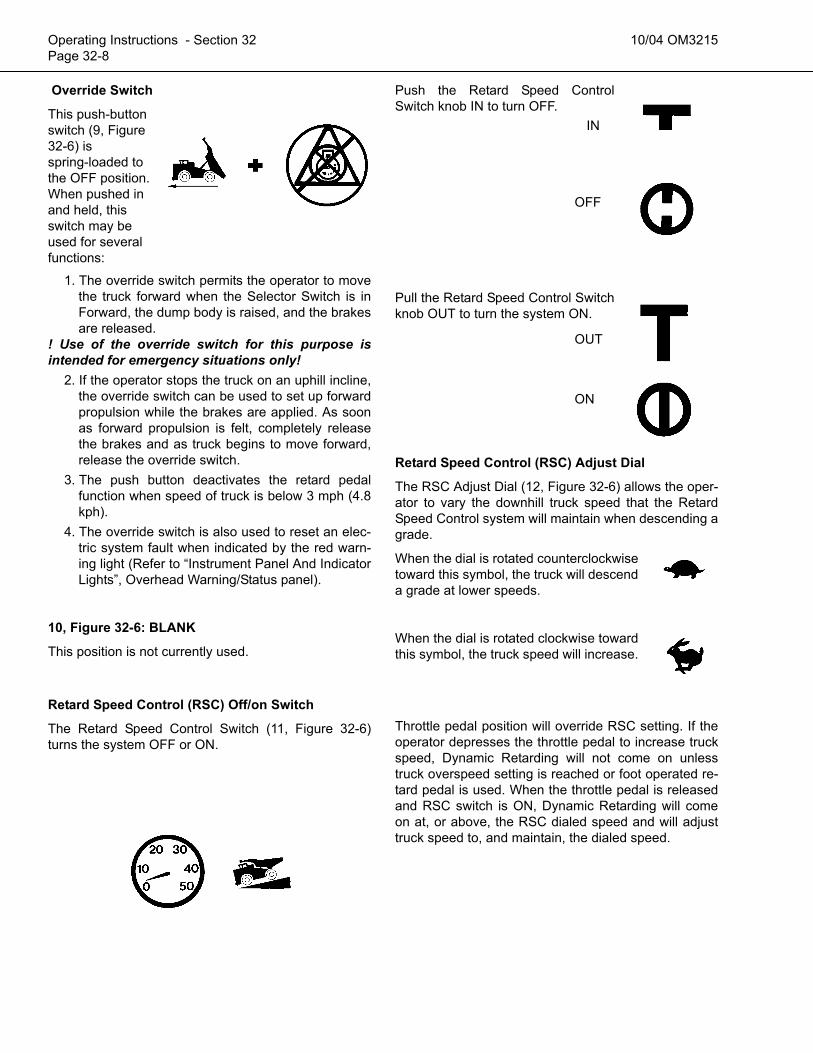
Operating Instructions - Section 32 10/04 OM3215Page 32-8
Override Switch
This push-button switch (9, Figure 32-6) is spring-loaded to the OFF position. When pushed in and held, this switch may be used for several functions:
1. The override switch permits the operator to movethe truck forward when the Selector Switch is inForward, the dump body is raised, and the brakesare released.
! Use of the override switch for this purpose isintended for emergency situations only!
2. If the operator stops the truck on an uphill incline,the override switch can be used to set up forwardpropulsion while the brakes are applied. As soonas forward propulsion is felt, completely releasethe brakes and as truck begins to move forward,release the override switch.
3. The push button deactivates the retard pedalfunction when speed of truck is below 3 mph (4.8kph).
4. The override switch is also used to reset an elec-tric system fault when indicated by the red warn-ing light (Refer to “Instrument Panel And IndicatorLights”, Overhead Warning/Status panel).
10, Figure 32-6: BLANK
This position is not currently used.
Retard Speed Control (RSC) Off/on Switch
The Retard Speed Control Switch (11, Figure 32-6)turns the system OFF or ON.
Push the Retard Speed ControlSwitch knob IN to turn OFF.
Pull the Retard Speed Control Switchknob OUT to turn the system ON.
Retard Speed Control (RSC) Adjust Dial
The RSC Adjust Dial (12, Figure 32-6) allows the oper-ator to vary the downhill truck speed that the RetardSpeed Control system will maintain when descending agrade.
When the dial is rotated counterclockwisetoward this symbol, the truck will descenda grade at lower speeds.
When the dial is rotated clockwise towardthis symbol, the truck speed will increase.
Throttle pedal position will override RSC setting. If theoperator depresses the throttle pedal to increase truckspeed, Dynamic Retarding will not come on unlesstruck overspeed setting is reached or foot operated re-tard pedal is used. When the throttle pedal is releasedand RSC switch is ON, Dynamic Retarding will comeon at, or above, the RSC dialed speed and will adjusttruck speed to, and maintain, the dialed speed.
OFF
OUT
ON
IN
OM3215 10/04 Operating Instructions - Section 32Page 32-9
To adjust the RSC control, pull switch (11) ON andstart with dial (12) rotated toward fastest speed whiledriving truck at desired maximum speed. Relax throttlepedal to let truck coast and turn RSC Adjusting Dialslowly counterclockwise until Dynamic Retarding is ac-tivated. Dynamic Retarding will now be activated auto-matically anytime the “set” speed is reached, the RSCswitch is ON, and throttle pedal is released.
With RSC switch ON and dial adjusted, the system willfunction as follows: As truck speed increases to the“set” speed and throttle pedal released, dynamic re-tarding will apply. As truck speed tries to increase, theamount of retarding effort will automatically adjust tokeep the selected speed. When truck speed de-creases, the retarding effort is reduced to maintain theselected speed. If truck speed continues to decrease toapproximately 3 mph (4.8 kph) below “set” speed, Dy-namic Retarding will turn off automatically. If truckspeed must be reduced further, the operator can turnthe Adjust Dial to a new setting or depress the foot op-erated retard pedal.
If the operator depresses the foot operated retardpedal and the retard effort called for is greater than thatfrom the automatic system, the foot pedal retard willoverride RSC.
Statex III Propulsion System Diagnostic Connector
This 9-pin connector (13, Figure 32-6) is for use byqualified personnel to access G.E. STATEX III electricpropulsion diagnostic information and data. Refer to“Section E” for additional information.
Komatsu Engine Quantum Connector
This connector (17, Figure 32-6) is for use by qualifiedpersonnel to access engine diagnostic information forthe QUANTUM system. Refer to engine manufacturer’sservice publications for troubleshooting information.
Komatsu Engine Cense Connector
This 3-pin connector (14, Figure 32-6) is for use byqualified personnel to access engine diagnostic infor-mation for the CENSE system. Refer to engine manu-facturer’s service publications for troubleshootinginformation.
Unused Connector
This connector (18, Figure 32-6) location is not usedfor this model truck.
Modular Mining Port Conector
This connector (15, Figure 32-6) location is used if theoptional Modular Mining System is installed on thetruck.
Data Store Button
This button (19, Figure 32-6) is for use by qualifiedmaintenance personnel to record in memory a “snap-shot” of the Statex III drive system.
Passenger Seat
The passenger seat (16, Figure 32-6) is mounted ontop of the right hand portion of the Center Consolestructure.
The area beneath the passenger seat provides a cabi-net for various 24 VDC electrical components. Refer to“Section D” for service involving any of these compo-nents.
Service Engine Light (Blue)
The service engine light (20, Figure32-6) will illuminate if a problem isdetected by the electronic enginemonitoring system.
Electric propulsion and dynamicretarding will still be available.
If this light is ON, notify maintenance personnel so theycan diagnose and repair the problem the next time thetruck is in the shop for repairs or at the next PM (Pre-ventative Maintenance) interval.
Payload Meter
The Payload Meter (1, Figure 32-7) is used to providemanagement with operational data such as tonnagehauled and cycle times. The download connector (2,Figure 32-7) is used with a special cable to allow thePayload Meter (1) to communicate with a PortableComputer.
Refer to Section 60, Optional Equipment, for a morecomplete description of the payload meter and its func-tions.
FIGURE 32-7. PAYLOAD METER III1. Payload Meter III 2. Download Connector

Operating Instructions - Section 32 10/04 OM3215Page 32-10
INSTRUMENT PANEL AND INDICATOR LIGHTS
CONTROL SYMBOLS
Many control functions are identified with international symbols that the operator should learn to recognize immedi-ately. The operator must understand the function and operation of each instrument and control. This knowledge is essential for proper and safe operation of the machine. The following symbols are general indicators and may appear in multiple locations and combinations on the instru-ment panel.
This symbol may be used alone or with another symbol. This symbol identifies the OFF position of a switch or control.
This symbol may be used alone or with another symbol. This symbol identifies the ON position of a switch or control.
This symbol identifies the PUSHED IN position of a push-pull switch or control.
This symbol identifies the PULLED OUT position of a push-pull switch or control.
This symbol when it appearson an indicator or control iden-tifies that this indicator or con-trol is NOT used.
This symbol identifies a rotarycontrol or switch. Rotate theknob clockwise or counter-clockwise for functions.
This symbol identifies a switchused to test or check a func-tion. Press the switch on theside near the symbol to per-form the test.
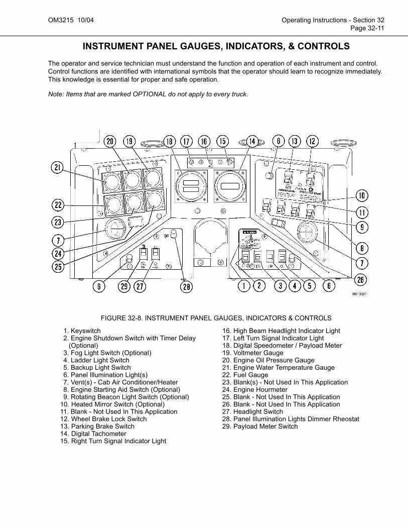
OM3215 10/04 Operating Instructions - Section 32Page 32-11
INSTRUMENT PANEL GAUGES, INDICATORS, & CONTROLSThe operator and service technician must understand the function and operation of each instrument and control. Control functions are identified with international symbols that the operator should learn to recognize immediately. This knowledge is essential for proper and safe operation.
Note: Items that are marked OPTIONAL do not apply to every truck.
FIGURE 32-8. INSTRUMENT PANEL GAUGES, INDICATORS & CONTROLS
1. Keyswitch2. Engine Shutdown Switch with Timer Delay
(Optional)3. Fog Light Switch (Optional)4. Ladder Light Switch 5. Backup Light Switch6. Panel Illumination Light(s)7. Vent(s) - Cab Air Conditioner/Heater8. Engine Starting Aid Switch (Optional)9. Rotating Beacon Light Switch (Optional)
10. Heated Mirror Switch (Optional)11. Blank - Not Used In This Application12. Wheel Brake Lock Switch 13. Parking Brake Switch 14. Digital Tachometer15. Right Turn Signal Indicator Light
16. High Beam Headlight Indicator Light17. Left Turn Signal Indicator Light18. Digital Speedometer / Payload Meter19. Voltmeter Gauge20. Engine Oil Pressure Gauge21. Engine Water Temperature Gauge22. Fuel Gauge23. Blank(s) - Not Used In This Application24. Engine Hourmeter25. Blank - Not Used In This Application26. Blank - Not Used In This Application27. Headlight Switch28. Panel Illumination Lights Dimmer Rheostat29. Payload Meter Switch
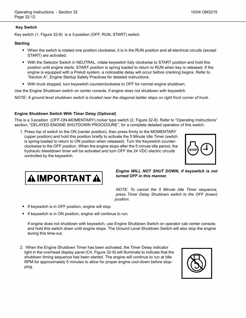
Operating Instructions - Section 32 10/04 OM3215Page 32-12
Key Switch
Key switch (1, Figure 32-8) is a 3-position (OFF, RUN, START) switch.
Starting• When the switch is rotated one position clockwise, it is in the RUN position and all electrical circuits (except
START) are activated.
• With the Selector Switch in NEUTRAL, rotate keyswitch fully clockwise to START position and hold this position until engine starts. START position is spring loaded to return to RUN when key is released. If the engine is equipped with a Prelub system, a noticeable delay will occur before cranking begins. Refer to “Section A”, Engine Startup Safety Practices for detailed instructions.
• With truck stopped, turn keyswitch counterclockwise to OFF for normal engine shutdown. Use the Engine Shutdown switch on center console, if engine does not shutdown with keyswitch.
NOTE: A ground level shutdown switch is located near the diagonal ladder steps on right front corner of truck.
Engine Shutdown Switch With Timer Delay (Optional)This is a 3-position (OFF-ON-MOMENTARY) rocker type switch (2, Figure 32-8). Refer to “Operating Instructions”section, “DELAYED ENGINE SHUTDOWN PROCEDURE”, for a complete detailed operation of this switch.
1. Press top of switch to the ON (center position), then press firmly to the MOMENTARY (upper position) and hold this position briefly to activate the 5 Minute Idle Timer (switch is spring-loaded to return to ON position when released). Turn the Keyswitch counter-clockwise to the OFF position. When the engine stops after the 5 minute idle period, the hydraulic bleeddown timer will be activated and turn OFF the 24 VDC electric circuits controlled by the keyswitch.
Engine WILL NOT SHUT DOWN, if keyswitch is notturned OFF in this manner.
NOTE: To cancel the 5 Minute Idle Timer sequence,press Timer Delay Shutdown switch to the OFF (lower)position.
• If keyswitch is in OFF position, engine will stop.
• If keyswitch is in ON position, engine will continue to run.
If engine does not shutdown with keyswitch, use Engine Shutdown Switch on operator cab center console, and hold this switch down until engine stops. The Ground Level Shutdown Switch will also stop the engine during this time-out.
2. When the Engine Shutdown Timer has been activated, the Timer Delay indicator light in the overhead display panel (C4, Figure 32-9) will illuminate to indicate that the shutdown timing sequence has been started. The engine will continue to run at Idle RPM for approximately 5 minutes to allow for proper engine cool-down before stop-ping.

OM3215 10/04 Operating Instructions - Section 32Page 32-13
Fog Lights (Optional)
Fog Lights (3, Figure 32-8) are optional equipment that are useful in foggy conditions and heavy rain. Pressing the top of the rocker switch turns the lights ON. Pressing the bottom of the switch turns the lights OFF.
Ladder Light Switch The switch turns the ladder lights (4, Figure 32-8) ON or OFF after or before using ladder.Pressing the top of the rocker switch turns the lights ON. Pressing the bottom of the switchturns the lights OFF. Another switch is mounted at the right front of truck near the base of theladder.
Manual Backup Switch The Manual Backup Switch (5, Figure 32-8) allows backup lights to be turned ON providingadded visibility and safety when the Selector Switch (see OPERATOR CONTROLS) is not inREV position. When the SWITCH is pressed toward the ON position, the MANUAL BACK UPLIGHT indicator (B4, Overhead Panel) will be illuminated.
Panel Illumination Lights Panel illumination lights (6, Figure 32-8) provide illumination for the instrument panel. Bright-ness is controlled by the panel light dimmer switch (28).
Cab Air Conditioner / Heater VentsThese vents (7, Figure 32-8) are spherically mounted and may be directed by the operator toprovide the most comfortable cabin air flow.
Engine Cold Weather Starting Aid (Optional)The OPTIONAL Engine Starting Aid switch (8, Figure 32-8) is spring-loaded to the OFF posi-tion. Use only when ambient temperature is below 50°F (10°C). When switch is held in theON position, ether is injected into the engine intake manifold to aid engine starting in coldweather. Move the Engine Starting Aid switch to the ON position while cranking engine, forthree (3) seconds maximum, and then release Engine Starting Aid. If engine does not start,wait at least fifteen (15) seconds before repeating the procedure. Refer to “Operating Instruc-tions”, for more specific operating details.
Rotating Beacon Light Switch (Optional)If truck is equipped with the OPTIONAL Rotating Beacon Light, it will be activated by thisrocker type switch (9, Figure 32-8) when it is pressed toward the ON position.
Heated Mirror Switch (Optional)If truck is equipped with the OPTIONAL Heated Mirror, it will be activated by this rocker typeswitch (10, Figure 32-8) when it is pressed toward the ON position.
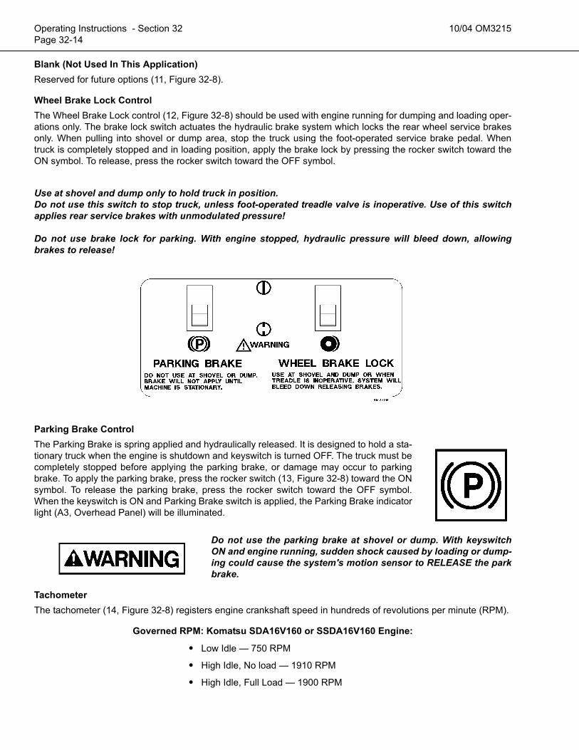
Operating Instructions - Section 32 10/04 OM3215Page 32-14
Blank (Not Used In This Application)Reserved for future options (11, Figure 32-8).
Wheel Brake Lock ControlThe Wheel Brake Lock control (12, Figure 32-8) should be used with engine running for dumping and loading oper-ations only. The brake lock switch actuates the hydraulic brake system which locks the rear wheel service brakesonly. When pulling into shovel or dump area, stop the truck using the foot-operated service brake pedal. Whentruck is completely stopped and in loading position, apply the brake lock by pressing the rocker switch toward theON symbol. To release, press the rocker switch toward the OFF symbol.
Use at shovel and dump only to hold truck in position.Do not use this switch to stop truck, unless foot-operated treadle valve is inoperative. Use of this switchapplies rear service brakes with unmodulated pressure!
Do not use brake lock for parking. With engine stopped, hydraulic pressure will bleed down, allowingbrakes to release!
Parking Brake ControlThe Parking Brake is spring applied and hydraulically released. It is designed to hold a sta-tionary truck when the engine is shutdown and keyswitch is turned OFF. The truck must becompletely stopped before applying the parking brake, or damage may occur to parkingbrake. To apply the parking brake, press the rocker switch (13, Figure 32-8) toward the ONsymbol. To release the parking brake, press the rocker switch toward the OFF symbol.When the keyswitch is ON and Parking Brake switch is applied, the Parking Brake indicatorlight (A3, Overhead Panel) will be illuminated.
Do not use the parking brake at shovel or dump. With keyswitchON and engine running, sudden shock caused by loading or dump-ing could cause the system's motion sensor to RELEASE the parkbrake.
TachometerThe tachometer (14, Figure 32-8) registers engine crankshaft speed in hundreds of revolutions per minute (RPM).
Governed RPM: Komatsu SDA16V160 or SSDA16V160 Engine:
• Low Idle — 750 RPM
• High Idle, No load — 1910 RPM
• High Idle, Full Load — 1900 RPM
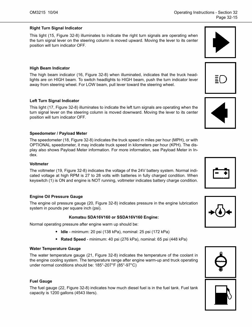
OM3215 10/04 Operating Instructions - Section 32Page 32-15
Right Turn Signal Indicator
This light (15, Figure 32-8) illuminates to indicate the right turn signals are operating whenthe turn signal lever on the steering column is moved upward. Moving the lever to its centerposition will turn indicator OFF.
High Beam Indicator The high beam indicator (16, Figure 32-8) when illuminated, indicates that the truck head-lights are on HIGH beam. To switch headlights to HIGH beam, push the turn indicator leveraway from steering wheel. For LOW beam, pull lever toward the steering wheel.
Left Turn Signal Indicator This light (17, Figure 32-8) illuminates to indicate the left turn signals are operating when theturn signal lever on the steering column is moved downward. Moving the lever to its centerposition will turn indicator OFF.
Speedometer / Payload MeterThe speedometer (18, Figure 32-8) indicates the truck speed in miles per hour (MPH), or withOPTIONAL speedometer, it may indicate truck speed in kilometers per hour (KPH). The dis-play also shows Payload Meter information. For more information, see Payload Meter in In-dex.
Voltmeter The voltmeter (19, Figure 32-8) indicates the voltage of the 24V battery system. Normal indi-cated voltage at high RPM is 27 to 28 volts with batteries in fully charged condition. Whenkeyswitch (1) is ON and engine is NOT running, voltmeter indicates battery charge condition.
Engine Oil Pressure GaugeThe engine oil pressure gauge (20, Figure 32-8) indicates pressure in the engine lubricationsystem in pounds per square inch (psi).
Komatsu SDA16V160 or SSDA16V160 Engine:Normal operating pressure after engine warm up should be:
• Idle - minimum: 20 psi (138 kPa), nominal: 25 psi (172 kPa)
• Rated Speed - minimum: 40 psi (276 kPa), nominal: 65 psi (448 kPa)
Water Temperature Gauge The water temperature gauge (21, Figure 32-8) indicates the temperature of the coolant inthe engine cooling system. The temperature range after engine warm-up and truck operatingunder normal conditions should be: 185°-207°F (85°-97°C)
Fuel GaugeThe fuel gauge (22, Figure 32-8) indicates how much diesel fuel is in the fuel tank. Fuel tankcapacity is 1200 gallons (4543 liters).
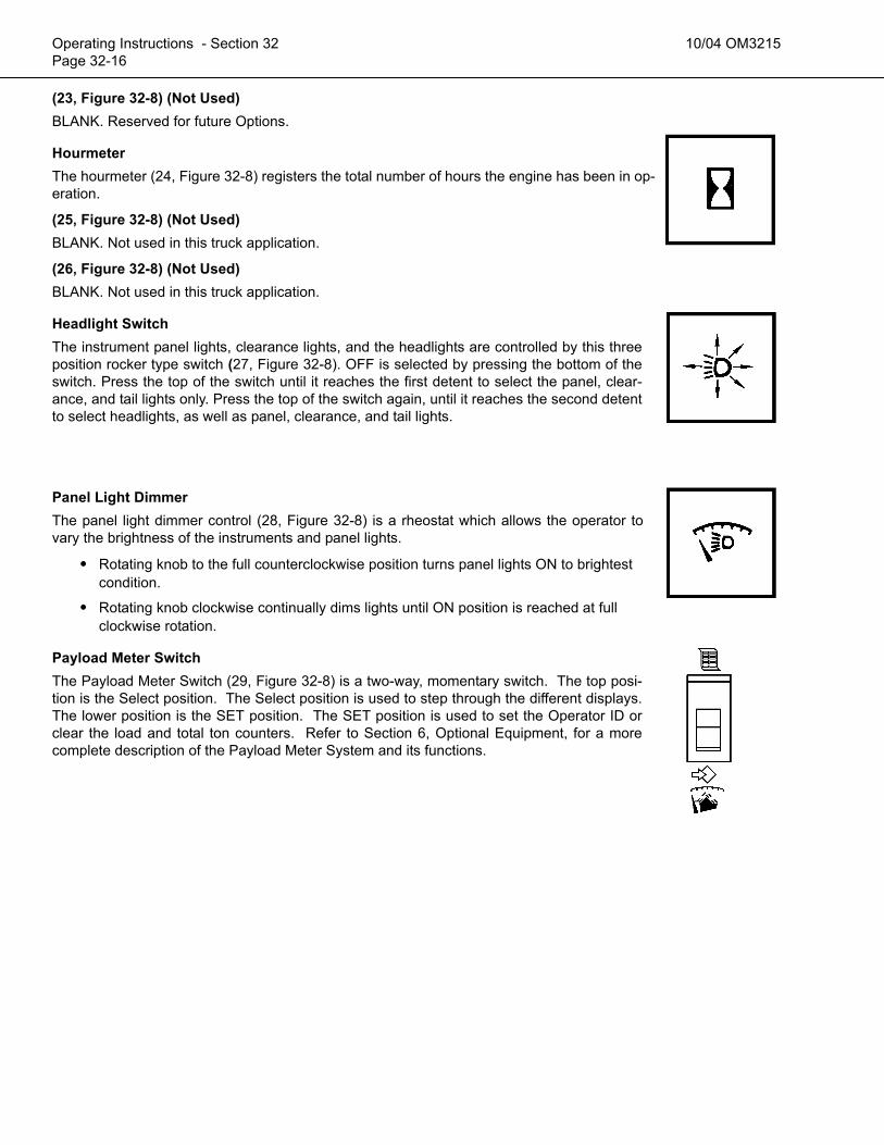
Operating Instructions - Section 32 10/04 OM3215Page 32-16
(23, Figure 32-8) (Not Used)BLANK. Reserved for future Options.
Hourmeter The hourmeter (24, Figure 32-8) registers the total number of hours the engine has been in op-eration.
(25, Figure 32-8) (Not Used)BLANK. Not used in this truck application.
(26, Figure 32-8) (Not Used)BLANK. Not used in this truck application.
Headlight SwitchThe instrument panel lights, clearance lights, and the headlights are controlled by this threeposition rocker type switch (27, Figure 32-8). OFF is selected by pressing the bottom of theswitch. Press the top of the switch until it reaches the first detent to select the panel, clear-ance, and tail lights only. Press the top of the switch again, until it reaches the second detentto select headlights, as well as panel, clearance, and tail lights.
Panel Light DimmerThe panel light dimmer control (28, Figure 32-8) is a rheostat which allows the operator tovary the brightness of the instruments and panel lights.
• Rotating knob to the full counterclockwise position turns panel lights ON to brightest condition.
• Rotating knob clockwise continually dims lights until ON position is reached at full clockwise rotation.
Payload Meter SwitchThe Payload Meter Switch (29, Figure 32-8) is a two-way, momentary switch. The top posi-tion is the Select position. The Select position is used to step through the different displays.The lower position is the SET position. The SET position is used to set the Operator ID orclear the load and total ton counters. Refer to Section 6, Optional Equipment, for a morecomplete description of the Payload Meter System and its functions.
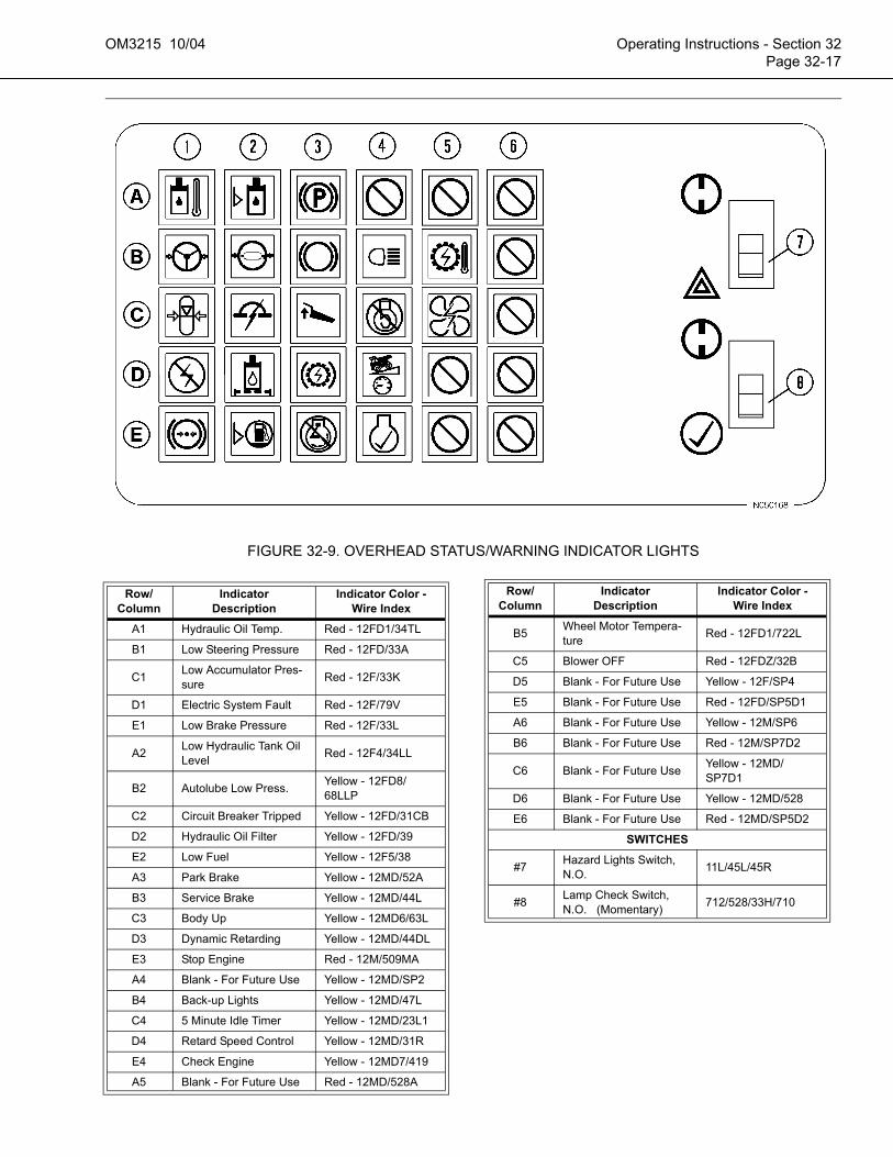
OM3215 10/04 Operating Instructions - Section 32Page 32-17
FIGURE 32-9. OVERHEAD STATUS/WARNING INDICATOR LIGHTS
Row/Column
IndicatorDescription
Indicator Color -Wire Index
A1 Hydraulic Oil Temp. Red - 12FD1/34TL
B1 Low Steering Pressure Red - 12FD/33A
C1 Low Accumulator Pres-sure Red - 12F/33K
D1 Electric System Fault Red - 12F/79V
E1 Low Brake Pressure Red - 12F/33L
A2 Low Hydraulic Tank Oil Level Red - 12F4/34LL
B2 Autolube Low Press. Yellow - 12FD8/68LLP
C2 Circuit Breaker Tripped Yellow - 12FD/31CB
D2 Hydraulic Oil Filter Yellow - 12FD/39
E2 Low Fuel Yellow - 12F5/38
A3 Park Brake Yellow - 12MD/52A
B3 Service Brake Yellow - 12MD/44L
C3 Body Up Yellow - 12MD6/63L
D3 Dynamic Retarding Yellow - 12MD/44DL
E3 Stop Engine Red - 12M/509MA
A4 Blank - For Future Use Yellow - 12MD/SP2
B4 Back-up Lights Yellow - 12MD/47L
C4 5 Minute Idle Timer Yellow - 12MD/23L1
D4 Retard Speed Control Yellow - 12MD/31R
E4 Check Engine Yellow - 12MD7/419
A5 Blank - For Future Use Red - 12MD/528A
B5 Wheel Motor Tempera-ture Red - 12FD1/722L
C5 Blower OFF Red - 12FDZ/32B
D5 Blank - For Future Use Yellow - 12F/SP4
E5 Blank - For Future Use Red - 12FD/SP5D1
A6 Blank - For Future Use Yellow - 12M/SP6
B6 Blank - For Future Use Red - 12M/SP7D2
C6 Blank - For Future Use Yellow - 12MD/SP7D1
D6 Blank - For Future Use Yellow - 12MD/528
E6 Blank - For Future Use Red - 12MD/SP5D2
SWITCHES
#7 Hazard Lights Switch, N.O. 11L/45L/45R
#8 Lamp Check Switch, N.O. (Momentary) 712/528/33H/710
Row/Column
IndicatorDescription
Indicator Color -Wire Index
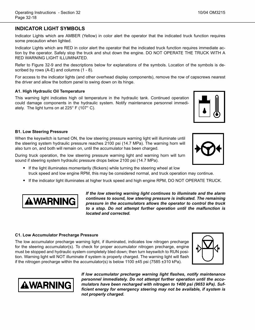
Operating Instructions - Section 32 10/04 OM3215Page 32-18
INDICATOR LIGHT SYMBOLSIndicator Lights which are AMBER (Yellow) in color alert the operator that the indicated truck function requiressome precaution when lighted.
Indicator Lights which are RED in color alert the operator that the indicated truck function requires immediate ac-tion by the operator. Safely stop the truck and shut down the engine. DO NOT OPERATE THE TRUCK WITH ARED WARNING LIGHT ILLUMINATED.
Refer to Figure 32-9 and the descriptions below for explanations of the symbols. Location of the symbols is de-scribed by rows (A-E) and columns (1 - 8).
For access to the indicator lights (and other overhead display components), remove the row of capscrews nearestthe driver and allow the bottom panel to swing down on its hinge.
A1. High Hydraulic Oil TemperatureThis warning light indicates high oil temperature in the hydraulic tank. Continued operationcould damage components in the hydraulic system. Notify maintenance personnel immedi-ately. The light turns on at 225° F (107° C).
B1. Low Steering PressureWhen the keyswitch is turned ON, the low steering pressure warning light will illuminate untilthe steering system hydraulic pressure reaches 2100 psi (14.7 MPa). The warning horn willalso turn on, and both will remain on, until the accumulator has been charged.
During truck operation, the low steering pressure warning light and warning horn will turnsound if steering system hydraulic pressure drops below 2100 psi (14.7 MPa).
• If the light illuminates momentarily (flickers) while turning the steering wheel at low truck speed and low engine RPM, this may be considered normal, and truck operation may continue.
• If the indicator light illuminates at higher truck speed and high engine RPM, DO NOT OPERATE TRUCK.
If the low steering warning light continues to illuminate and the alarmcontinues to sound, low steering pressure is indicated. The remainingpressure in the accumulators allows the operator to control the truckto a stop. Do not attempt further operation until the malfunction islocated and corrected.
C1. Low Accumulator Precharge PressureThe low accumulator precharge warning light, if illuminated, indicates low nitrogen prechargefor the steering accumulator(s). To check for proper accumulator nitrogen precharge, enginemust be stopped and hydraulic system completely bled down; then turn keyswitch to RUN posi-tion. Warning light will NOT illuminate if system is properly charged. The warning light will flashif the nitrogen precharge within the accumulator(s) is below 1100 ±45 psi (7585 ±310 kPa).
If low accumulator precharge warning light flashes, notify maintenancepersonnel immediately. Do not attempt further operation until the accu-mulators have been recharged with nitrogen to 1400 psi (9653 kPa). Suf-ficient energy for emergency steering may not be available, if system isnot properly charged.
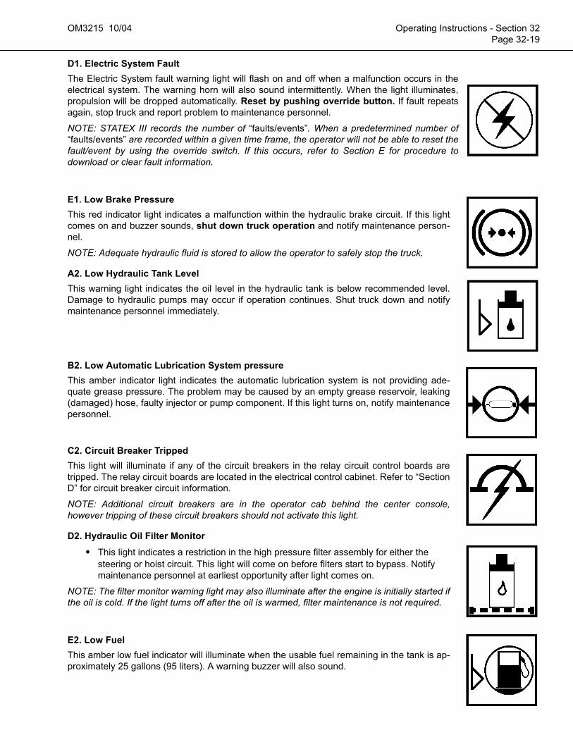
OM3215 10/04 Operating Instructions - Section 32Page 32-19
D1. Electric System FaultThe Electric System fault warning light will flash on and off when a malfunction occurs in theelectrical system. The warning horn will also sound intermittently. When the light illuminates,propulsion will be dropped automatically. Reset by pushing override button. If fault repeatsagain, stop truck and report problem to maintenance personnel.
NOTE: STATEX III records the number of “faults/events”. When a predetermined number of“faults/events” are recorded within a given time frame, the operator will not be able to reset thefault/event by using the override switch. If this occurs, refer to Section E for procedure todownload or clear fault information.
E1. Low Brake Pressure This red indicator light indicates a malfunction within the hydraulic brake circuit. If this lightcomes on and buzzer sounds, shut down truck operation and notify maintenance person-nel.
NOTE: Adequate hydraulic fluid is stored to allow the operator to safely stop the truck.
A2. Low Hydraulic Tank LevelThis warning light indicates the oil level in the hydraulic tank is below recommended level.Damage to hydraulic pumps may occur if operation continues. Shut truck down and notifymaintenance personnel immediately.
B2. Low Automatic Lubrication System pressureThis amber indicator light indicates the automatic lubrication system is not providing ade-quate grease pressure. The problem may be caused by an empty grease reservoir, leaking(damaged) hose, faulty injector or pump component. If this light turns on, notify maintenancepersonnel.
C2. Circuit Breaker TrippedThis light will illuminate if any of the circuit breakers in the relay circuit control boards aretripped. The relay circuit boards are located in the electrical control cabinet. Refer to “SectionD” for circuit breaker circuit information.
NOTE: Additional circuit breakers are in the operator cab behind the center console,however tripping of these circuit breakers should not activate this light.
D2. Hydraulic Oil Filter Monitor• This light indicates a restriction in the high pressure filter assembly for either the
steering or hoist circuit. This light will come on before filters start to bypass. Notify maintenance personnel at earliest opportunity after light comes on.
NOTE: The filter monitor warning light may also illuminate after the engine is initially started ifthe oil is cold. If the light turns off after the oil is warmed, filter maintenance is not required.
E2. Low FuelThis amber low fuel indicator will illuminate when the usable fuel remaining in the tank is ap-proximately 25 gallons (95 liters). A warning buzzer will also sound.
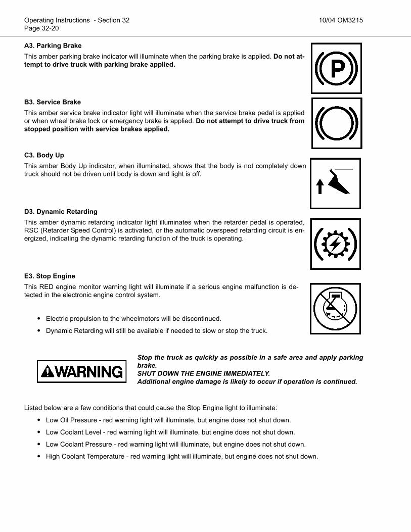
Operating Instructions - Section 32 10/04 OM3215Page 32-20
A3. Parking BrakeThis amber parking brake indicator will illuminate when the parking brake is applied. Do not at-tempt to drive truck with parking brake applied.
B3. Service Brake This amber service brake indicator light will illuminate when the service brake pedal is appliedor when wheel brake lock or emergency brake is applied. Do not attempt to drive truck fromstopped position with service brakes applied.
C3. Body Up This amber Body Up indicator, when illuminated, shows that the body is not completely down on the frame. Thetruck should not be driven until body is down and light is off.
D3. Dynamic RetardingThis amber dynamic retarding indicator light illuminates when the retarder pedal is operated,RSC (Retarder Speed Control) is activated, or the automatic overspeed retarding circuit is en-ergized, indicating the dynamic retarding function of the truck is operating.
E3. Stop EngineThis RED engine monitor warning light will illuminate if a serious engine malfunction is de-tected in the electronic engine control system.
• Electric propulsion to the wheelmotors will be discontinued.
• Dynamic Retarding will still be available if needed to slow or stop the truck.
Stop the truck as quickly as possible in a safe area and apply parkingbrake. SHUT DOWN THE ENGINE IMMEDIATELY.Additional engine damage is likely to occur if operation is continued.
Listed below are a few conditions that could cause the Stop Engine light to illuminate:
• Low Oil Pressure - red warning light will illuminate, but engine does not shut down.
• Low Coolant Level - red warning light will illuminate, but engine does not shut down.
• Low Coolant Pressure - red warning light will illuminate, but engine does not shut down.
• High Coolant Temperature - red warning light will illuminate, but engine does not shut down.
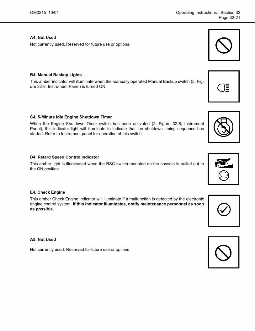
OM3215 10/04 Operating Instructions - Section 32Page 32-21
A4. Not UsedNot currently used. Reserved for future use or options.
B4. Manual Backup LightsThis amber indicator will illuminate when the manually operated Manual Backup switch (5, Fig-ure 32-8, Instrument Panel) is turned ON.
C4. 5-Minute Idle Engine Shutdown Timer When the Engine Shutdown Timer switch has been activated (2, Figure 32-8, InstrumentPanel), this indicator light will illuminate to indicate that the shutdown timing sequence hasstarted. Refer to Instrument panel for operation of this switch.
D4. Retard Speed Control IndicatorThis amber light is illuminated when the RSC switch mounted on the console is pulled out tothe ON position.
E4. Check Engine This amber Check Engine indicator will illuminate if a malfunction is detected by the electronicengine control system. If this indicator illuminates, notify maintenance personnel as soonas possible.
A5. Not Used
Not currently used. Reserved for future use or options.
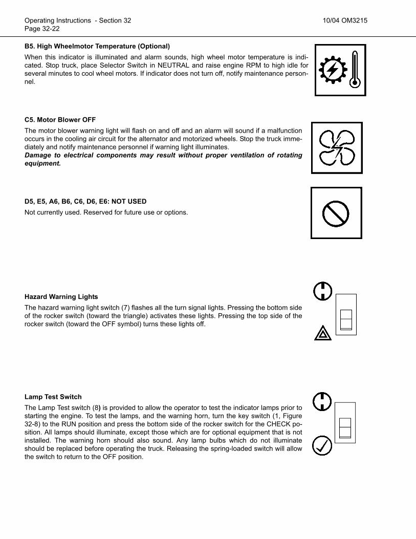
Operating Instructions - Section 32 10/04 OM3215Page 32-22
B5. High Wheelmotor Temperature (Optional) When this indicator is illuminated and alarm sounds, high wheel motor temperature is indi-cated. Stop truck, place Selector Switch in NEUTRAL and raise engine RPM to high idle forseveral minutes to cool wheel motors. If indicator does not turn off, notify maintenance person-nel.
C5. Motor Blower OFF The motor blower warning light will flash on and off and an alarm will sound if a malfunctionoccurs in the cooling air circuit for the alternator and motorized wheels. Stop the truck imme-diately and notify maintenance personnel if warning light illuminates. Damage to electrical components may result without proper ventilation of rotatingequipment.
D5, E5, A6, B6, C6, D6, E6: NOT USEDNot currently used. Reserved for future use or options.
Hazard Warning Lights The hazard warning light switch (7) flashes all the turn signal lights. Pressing the bottom sideof the rocker switch (toward the triangle) activates these lights. Pressing the top side of therocker switch (toward the OFF symbol) turns these lights off.
Lamp Test SwitchThe Lamp Test switch (8) is provided to allow the operator to test the indicator lamps prior tostarting the engine. To test the lamps, and the warning horn, turn the key switch (1, Figure32-8) to the RUN position and press the bottom side of the rocker switch for the CHECK po-sition. All lamps should illuminate, except those which are for optional equipment that is notinstalled. The warning horn should also sound. Any lamp bulbs which do not illuminateshould be replaced before operating the truck. Releasing the spring-loaded switch will allowthe switch to return to the OFF position.
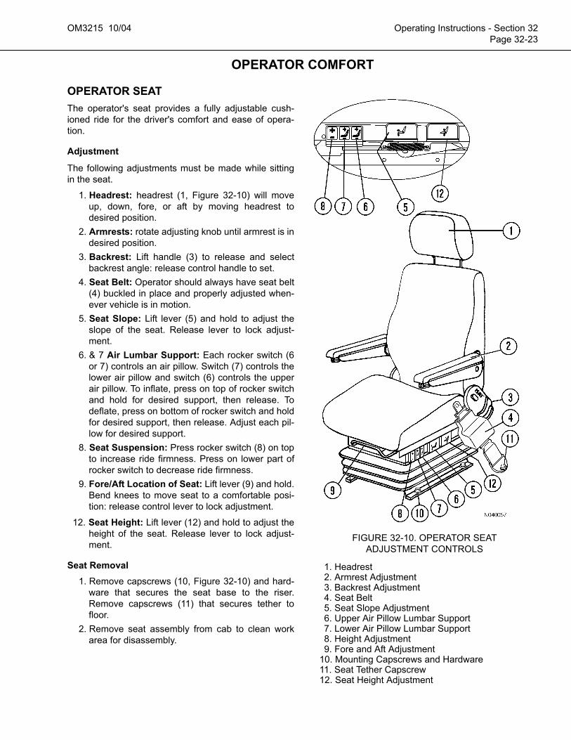
OM3215 10/04 Operating Instructions - Section 32Page 32-23
OPERATOR COMFORT
OPERATOR SEAT The operator's seat provides a fully adjustable cush-ioned ride for the driver's comfort and ease of opera-tion.
Adjustment
The following adjustments must be made while sittingin the seat.
1. Headrest: headrest (1, Figure 32-10) will moveup, down, fore, or aft by moving headrest todesired position.
2. Armrests: rotate adjusting knob until armrest is indesired position.
3. Backrest: Lift handle (3) to release and selectbackrest angle: release control handle to set.
4. Seat Belt: Operator should always have seat belt(4) buckled in place and properly adjusted when-ever vehicle is in motion.
5. Seat Slope: Lift lever (5) and hold to adjust theslope of the seat. Release lever to lock adjust-ment.
6. & 7 Air Lumbar Support: Each rocker switch (6or 7) controls an air pillow. Switch (7) controls thelower air pillow and switch (6) controls the upperair pillow. To inflate, press on top of rocker switchand hold for desired support, then release. Todeflate, press on bottom of rocker switch and holdfor desired support, then release. Adjust each pil-low for desired support.
8. Seat Suspension: Press rocker switch (8) on topto increase ride firmness. Press on lower part ofrocker switch to decrease ride firmness.
9. Fore/Aft Location of Seat: Lift lever (9) and hold.Bend knees to move seat to a comfortable posi-tion: release control lever to lock adjustment.
12. Seat Height: Lift lever (12) and hold to adjust theheight of the seat. Release lever to lock adjust-ment.
Seat Removal1. Remove capscrews (10, Figure 32-10) and hard-
ware that secures the seat base to the riser.Remove capscrews (11) that secures tether tofloor.
2. Remove seat assembly from cab to clean workarea for disassembly.
FIGURE 32-10. OPERATOR SEATADJUSTMENT CONTROLS
1. Headrest 2. Armrest Adjustment 3. Backrest Adjustment4. Seat Belt5. Seat Slope Adjustment6. Upper Air Pillow Lumbar Support7. Lower Air Pillow Lumbar Support8. Height Adjustment 9. Fore and Aft Adjustment
10. Mounting Capscrews and Hardware11. Seat Tether Capscrew12. Seat Height Adjustment

Operating Instructions - Section 32 10/04 OM3215Page 32-24
Seat Installation1. Mount seat assembly to seat riser. Install cap-
screws (10, Figure 32-10), lockwashers, flatwash-ers and nuts. Tighten capscrews to standardtorque.
2. Fasten tether straps to floor with capscrews (11),flatwashers and lockwashers. Tighten capscrewsto standard torque.
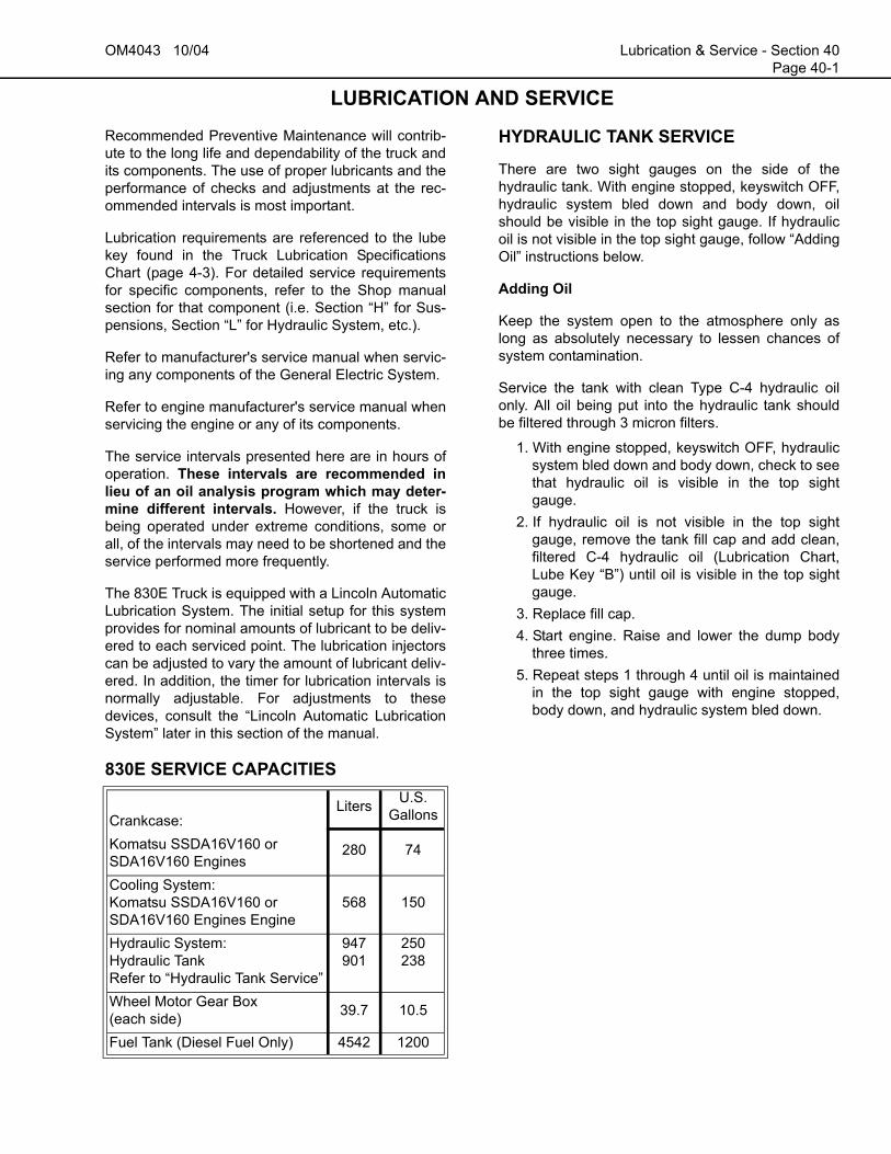
OM4043 10/04 Lubrication & Service - Section 40Page 40-1
LUBRICATION AND SERVICERecommended Preventive Maintenance will contrib-ute to the long life and dependability of the truck andits components. The use of proper lubricants and theperformance of checks and adjustments at the rec-ommended intervals is most important.
Lubrication requirements are referenced to the lubekey found in the Truck Lubrication SpecificationsChart (page 4-3). For detailed service requirementsfor specific components, refer to the Shop manualsection for that component (i.e. Section “H” for Sus-pensions, Section “L” for Hydraulic System, etc.).
Refer to manufacturer's service manual when servic-ing any components of the General Electric System.
Refer to engine manufacturer's service manual whenservicing the engine or any of its components.
The service intervals presented here are in hours ofoperation. These intervals are recommended inlieu of an oil analysis program which may deter-mine different intervals. However, if the truck isbeing operated under extreme conditions, some orall, of the intervals may need to be shortened and theservice performed more frequently.
The 830E Truck is equipped with a Lincoln AutomaticLubrication System. The initial setup for this systemprovides for nominal amounts of lubricant to be deliv-ered to each serviced point. The lubrication injectorscan be adjusted to vary the amount of lubricant deliv-ered. In addition, the timer for lubrication intervals isnormally adjustable. For adjustments to thesedevices, consult the “Lincoln Automatic LubricationSystem” later in this section of the manual.
830E SERVICE CAPACITIES
HYDRAULIC TANK SERVICE
There are two sight gauges on the side of thehydraulic tank. With engine stopped, keyswitch OFF,hydraulic system bled down and body down, oilshould be visible in the top sight gauge. If hydraulicoil is not visible in the top sight gauge, follow “AddingOil” instructions below.
Adding Oil
Keep the system open to the atmosphere only aslong as absolutely necessary to lessen chances ofsystem contamination.
Service the tank with clean Type C-4 hydraulic oilonly. All oil being put into the hydraulic tank shouldbe filtered through 3 micron filters.
1. With engine stopped, keyswitch OFF, hydraulicsystem bled down and body down, check to seethat hydraulic oil is visible in the top sightgauge.
2. If hydraulic oil is not visible in the top sightgauge, remove the tank fill cap and add clean,filtered C-4 hydraulic oil (Lubrication Chart,Lube Key “B”) until oil is visible in the top sightgauge.
3. Replace fill cap. 4. Start engine. Raise and lower the dump body
three times.5. Repeat steps 1 through 4 until oil is maintained
in the top sight gauge with engine stopped,body down, and hydraulic system bled down.
Crankcase:Komatsu SSDA16V160 or SDA16V160 Engines
Liters U.S.Gallons
280 74
Cooling System:Komatsu SSDA16V160 or SDA16V160 Engines Engine
568 150
Hydraulic System:Hydraulic TankRefer to “Hydraulic Tank Service”
947901
250238
Wheel Motor Gear Box(each side) 39.7 10.5
Fuel Tank (Diesel Fuel Only) 4542 1200
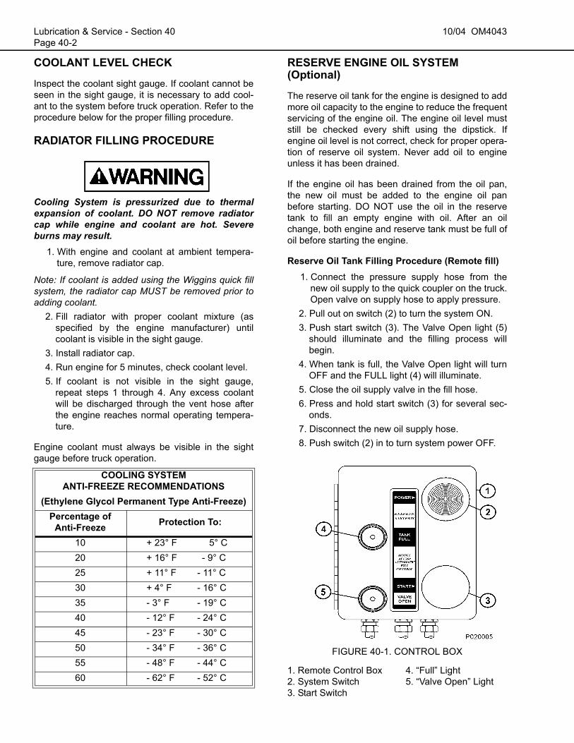
Lubrication & Service - Section 40 10/04 OM4043Page 40-2
COOLANT LEVEL CHECK
Inspect the coolant sight gauge. If coolant cannot beseen in the sight gauge, it is necessary to add cool-ant to the system before truck operation. Refer to theprocedure below for the proper filling procedure.
RADIATOR FILLING PROCEDURE
Cooling System is pressurized due to thermalexpansion of coolant. DO NOT remove radiatorcap while engine and coolant are hot. Severeburns may result.
1. With engine and coolant at ambient tempera-ture, remove radiator cap.
Note: If coolant is added using the Wiggins quick fillsystem, the radiator cap MUST be removed prior toadding coolant.
2. Fill radiator with proper coolant mixture (asspecified by the engine manufacturer) untilcoolant is visible in the sight gauge.
3. Install radiator cap.4. Run engine for 5 minutes, check coolant level.5. If coolant is not visible in the sight gauge,
repeat steps 1 through 4. Any excess coolantwill be discharged through the vent hose afterthe engine reaches normal operating tempera-ture.
Engine coolant must always be visible in the sightgauge before truck operation.
RESERVE ENGINE OIL SYSTEM (Optional)
The reserve oil tank for the engine is designed to addmore oil capacity to the engine to reduce the frequentservicing of the engine oil. The engine oil level muststill be checked every shift using the dipstick. Ifengine oil level is not correct, check for proper opera-tion of reserve oil system. Never add oil to engineunless it has been drained.
If the engine oil has been drained from the oil pan,the new oil must be added to the engine oil panbefore starting. DO NOT use the oil in the reservetank to fill an empty engine with oil. After an oilchange, both engine and reserve tank must be full ofoil before starting the engine.
Reserve Oil Tank Filling Procedure (Remote fill)1. Connect the pressure supply hose from the
new oil supply to the quick coupler on the truck.Open valve on supply hose to apply pressure.
2. Pull out on switch (2) to turn the system ON.3. Push start switch (3). The Valve Open light (5)
should illuminate and the filling process willbegin.
4. When tank is full, the Valve Open light will turnOFF and the FULL light (4) will illuminate.
5. Close the oil supply valve in the fill hose.6. Press and hold start switch (3) for several sec-
onds.7. Disconnect the new oil supply hose.8. Push switch (2) in to turn system power OFF.
FIGURE 40-1. CONTROL BOX
COOLING SYSTEMANTI-FREEZE RECOMMENDATIONS
(Ethylene Glycol Permanent Type Anti-Freeze)Percentage of
Anti-Freeze Protection To:
10 + 23° F 5° C20 + 16° F - 9° C25 + 11° F - 11° C30 + 4° F - 16° C35 - 3° F - 19° C40 - 12° F - 24° C45 - 23° F - 30° C50 - 34° F - 36° C55 - 48° F - 44° C60 - 62° F - 52° C
1. Remote Control Box2. System Switch3. Start Switch
4. “Full” Light5. “Valve Open” Light
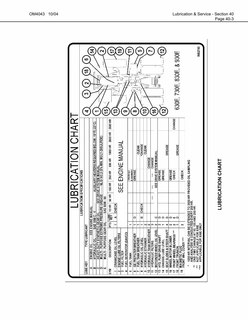
OM4043 10/04 Lubrication & Service - Section 40Page 40-3
LUB
RIC
ATIO
N C
HA
RT
Lubrication & Service - Section 40 10/04 OM4043Page 40-4
10 HOUR (DAILY) INSPECTIONPrior to each operating shift, a “walk around” inspec-tion should be performed. Check the truck for generalcondition. Look for evidence of hydraulic leaks;check all lights and mirrors for clean and unbrokenlenses; check operator's cab for clean and unbrokenglass; check frame, sheet metal and body for cracks.Notify the proper maintenance authority if any dis-crepancies are found. Give particular attention to thefollowing:
10 HOUR LUBRICATION AND MAINTENANCE CHECKS
1. FAN DRIVE AND TURBOCHARGERS - Checkfor leaks, vibration or unusual noise. Checkalternator and fan belts for proper tension, con-dition and for alignment.
2. RADIATOR - Check coolant level and fill withproper mixture as shown in Cooling SystemRecommendation Chart. Refer to Engine Man-ual for proper coolant additives.
3. ENGINE - Check oil level on dipstick. Refer toengine manufacturer's shop manual for oil rec-ommendations. (Lube Key “A”).
• Inspect exhaust piping for security. • Centinel - Check reservoir oil level • Eliminator Filter - Check operating indicator
NOTE: If truck is equipped with a reserve engine oiltank, the oil should be visible in the center (middle)sight gauge. If not, add oil to reserve tank until oil isvisible in top sight gauge. Also, with engine running,check operation of the LED indicator light. See belowfor description of LED Light Signals.
LED Light Signals:
• Steady - Pump 1 is withdrawing oil from theengine sump and bringing down the oil level.
• Regular Pulsing - Pump 2 is returning oil to theengine sump and raising the oil level.
• Irregular Pulsing - Oil is at the correct runninglevel.
4. FUEL FILTERS (Fuel Separators) - Drain waterfrom bottom of each filter housing.
5. HYDRAULIC TANK - Check oil level in tank,add oil if necessary. Refer to “Hydraulic TankService”. Oil should be visible in top sight glass.- DO NOT OVERFILL. Lube Key “B”.
Truck Serial Number ________________________
Site Unit Number ____________________________
Date: __________ Hour Meter _________________
Name of Service Person ______________________
COMMENTS CHECKED INITIALS
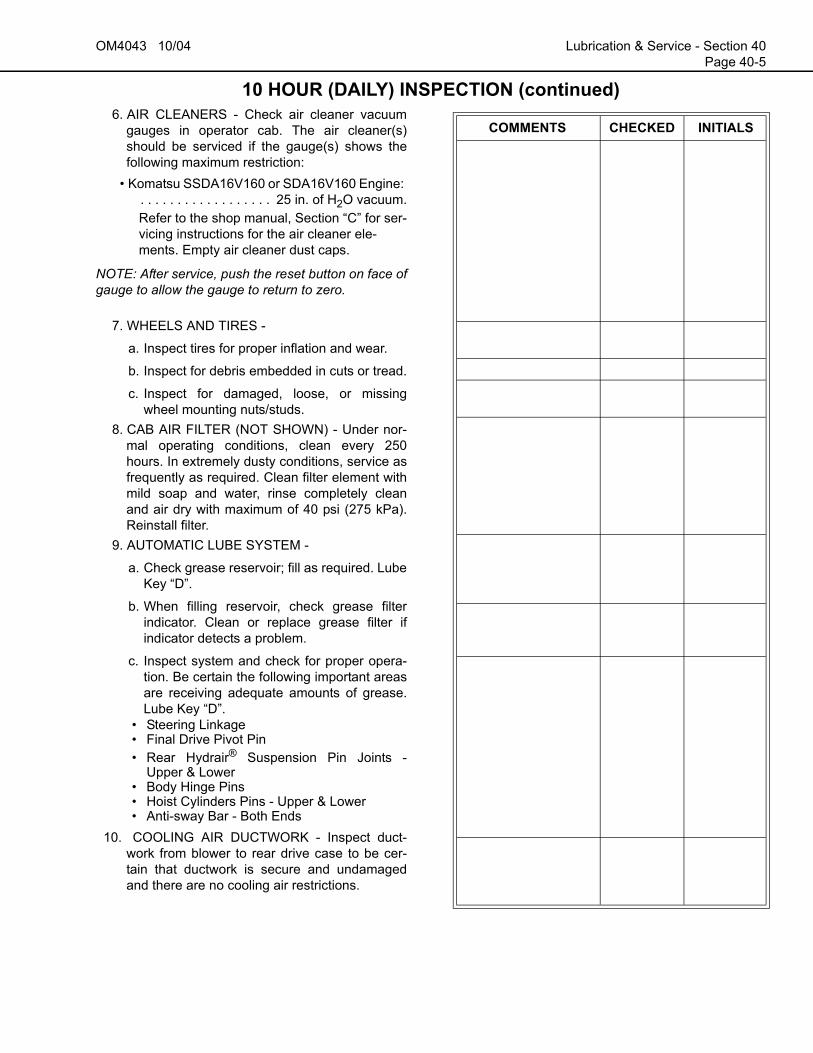
OM4043 10/04 Lubrication & Service - Section 40Page 40-5
10 HOUR (DAILY) INSPECTION (continued)6. AIR CLEANERS - Check air cleaner vacuum
gauges in operator cab. The air cleaner(s)should be serviced if the gauge(s) shows thefollowing maximum restriction:
• Komatsu SSDA16V160 or SDA16V160 Engine: . . . . . . . . . . . . . . . . . . 25 in. of H2O vacuum.Refer to the shop manual, Section “C” for ser-vicing instructions for the air cleaner ele-ments. Empty air cleaner dust caps.
NOTE: After service, push the reset button on face ofgauge to allow the gauge to return to zero.
7. WHEELS AND TIRES -
a. Inspect tires for proper inflation and wear.
b. Inspect for debris embedded in cuts or tread.
c. Inspect for damaged, loose, or missingwheel mounting nuts/studs.
8. CAB AIR FILTER (NOT SHOWN) - Under nor-mal operating conditions, clean every 250hours. In extremely dusty conditions, service asfrequently as required. Clean filter element withmild soap and water, rinse completely cleanand air dry with maximum of 40 psi (275 kPa).Reinstall filter.
9. AUTOMATIC LUBE SYSTEM -
a. Check grease reservoir; fill as required. LubeKey “D”.
b. When filling reservoir, check grease filterindicator. Clean or replace grease filter ifindicator detects a problem.
c. Inspect system and check for proper opera-tion. Be certain the following important areasare receiving adequate amounts of grease.Lube Key “D”.
• Steering Linkage • Final Drive Pivot Pin • Rear Hydrair® Suspension Pin Joints -
Upper & Lower • Body Hinge Pins • Hoist Cylinders Pins - Upper & Lower • Anti-sway Bar - Both Ends
10. COOLING AIR DUCTWORK - Inspect duct-work from blower to rear drive case to be cer-tain that ductwork is secure and undamagedand there are no cooling air restrictions.
COMMENTS CHECKED INITIALS
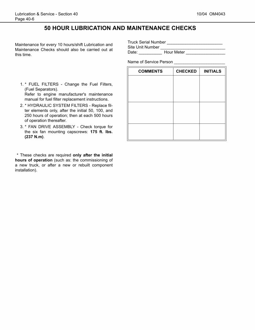
Lubrication & Service - Section 40 10/04 OM4043Page 40-6
50 HOUR LUBRICATION AND MAINTENANCE CHECKS
Maintenance for every 10 hours/shift Lubrication andMaintenance Checks should also be carried out atthis time.
1. * FUEL FILTERS - Change the Fuel Filters,(Fuel Separators).Refer to engine manufacturer's maintenancemanual for fuel filter replacement instructions.
2. * HYDRAULIC SYSTEM FILTERS - Replace fil-ter elements only, after the initial 50, 100, and250 hours of operation; then at each 500 hoursof operation thereafter.
3. * FAN DRIVE ASSEMBLY - Check torque forthe six fan mounting capscrews: 175 ft. lbs.(237 N.m).
* These checks are required only after the initialhours of operation (such as: the commissioning ofa new truck, or after a new or rebuilt componentinstallation).
Truck Serial Number ________________________Site Unit Number ____________________________Date: __________ Hour Meter _________________
Name of Service Person ______________________
COMMENTS CHECKED INITIALS
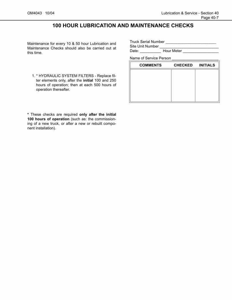
OM4043 10/04 Lubrication & Service - Section 40Page 40-7
100 HOUR LUBRICATION AND MAINTENANCE CHECKS
Maintenance for every 10 & 50 hour Lubrication andMaintenance Checks should also be carried out atthis time.
1. * HYDRAULIC SYSTEM FILTERS - Replace fil-ter elements only, after the initial 100 and 250hours of operation; then at each 500 hours ofoperation thereafter.
* These checks are required only after the initial100 hours of operation (such as: the commission-ing of a new truck, or after a new or rebuilt compo-nent installation).
Truck Serial Number ________________________Site Unit Number ____________________________Date: __________ Hour Meter _________________
Name of Service Person ______________________
COMMENTS CHECKED INITIALS
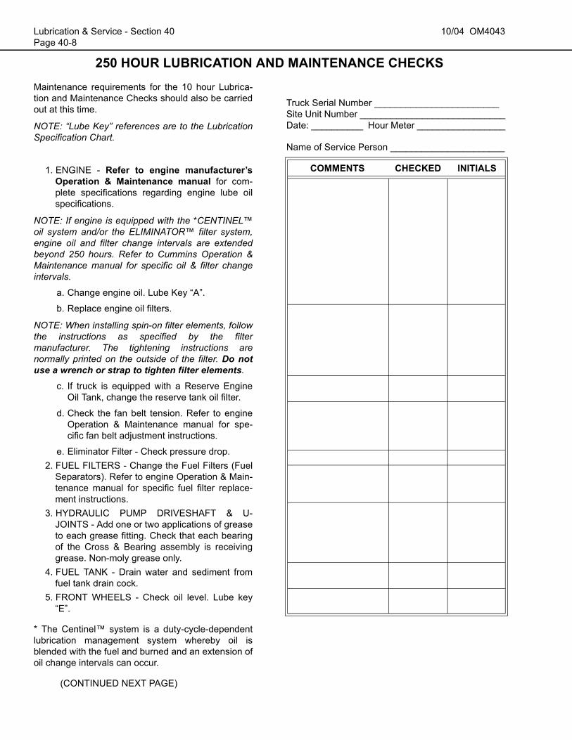
Lubrication & Service - Section 40 10/04 OM4043Page 40-8
250 HOUR LUBRICATION AND MAINTENANCE CHECKSMaintenance requirements for the 10 hour Lubrica-tion and Maintenance Checks should also be carriedout at this time.
NOTE: “Lube Key” references are to the LubricationSpecification Chart.
1. ENGINE - Refer to engine manufacturer’sOperation & Maintenance manual for com-plete specifications regarding engine lube oilspecifications.
NOTE: If engine is equipped with the *CENTINEL™oil system and/or the ELIMINATOR™ filter system,engine oil and filter change intervals are extendedbeyond 250 hours. Refer to Cummins Operation &Maintenance manual for specific oil & filter changeintervals.
a. Change engine oil. Lube Key “A”.
b. Replace engine oil filters.
NOTE: When installing spin-on filter elements, followthe instructions as specified by the filtermanufacturer. The tightening instructions arenormally printed on the outside of the filter. Do notuse a wrench or strap to tighten filter elements.
c. If truck is equipped with a Reserve EngineOil Tank, change the reserve tank oil filter.
d. Check the fan belt tension. Refer to engineOperation & Maintenance manual for spe-cific fan belt adjustment instructions.
e. Eliminator Filter - Check pressure drop.2. FUEL FILTERS - Change the Fuel Filters (Fuel
Separators). Refer to engine Operation & Main-tenance manual for specific fuel filter replace-ment instructions.
3. HYDRAULIC PUMP DRIVESHAFT & U-JOINTS - Add one or two applications of greaseto each grease fitting. Check that each bearingof the Cross & Bearing assembly is receivinggrease. Non-moly grease only.
4. FUEL TANK - Drain water and sediment fromfuel tank drain cock.
5. FRONT WHEELS - Check oil level. Lube key“E”.
* The Centinel™ system is a duty-cycle-dependentlubrication management system whereby oil isblended with the fuel and burned and an extension ofoil change intervals can occur.
(CONTINUED NEXT PAGE)
Truck Serial Number ________________________Site Unit Number ____________________________Date: __________ Hour Meter _________________
Name of Service Person ______________________
COMMENTS CHECKED INITIALS
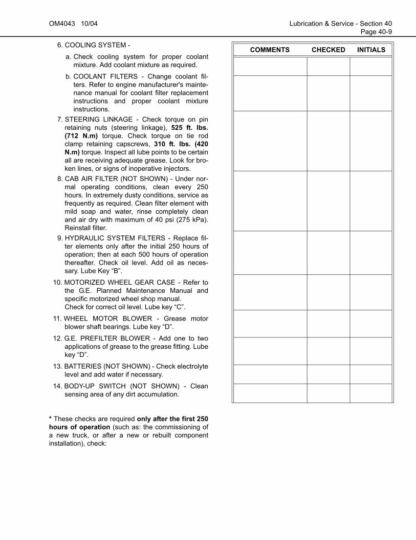
OM4043 10/04 Lubrication & Service - Section 40Page 40-9
6. COOLING SYSTEM -
a. Check cooling system for proper coolantmixture. Add coolant mixture as required.
b. COOLANT FILTERS - Change coolant fil-ters. Refer to engine manufacturer's mainte-nance manual for coolant filter replacementinstructions and proper coolant mixtureinstructions.
7. STEERING LINKAGE - Check torque on pinretaining nuts (steering linkage), 525 ft. lbs.(712 N.m) torque. Check torque on tie rodclamp retaining capscrews, 310 ft. lbs. (420N.m) torque. Inspect all lube points to be certainall are receiving adequate grease. Look for bro-ken lines, or signs of inoperative injectors.
8. CAB AIR FILTER (NOT SHOWN) - Under nor-mal operating conditions, clean every 250hours. In extremely dusty conditions, service asfrequently as required. Clean filter element withmild soap and water, rinse completely cleanand air dry with maximum of 40 psi (275 kPa).Reinstall filter.
9. HYDRAULIC SYSTEM FILTERS - Replace fil-ter elements only after the initial 250 hours ofoperation; then at each 500 hours of operationthereafter. Check oil level. Add oil as neces-sary. Lube Key “B”.
10. MOTORIZED WHEEL GEAR CASE - Refer tothe G.E. Planned Maintenance Manual andspecific motorized wheel shop manual.Check for correct oil level. Lube key “C”.
11. WHEEL MOTOR BLOWER - Grease motorblower shaft bearings. Lube key “D”.
12. G.E. PREFILTER BLOWER - Add one to twoapplications of grease to the grease fitting. Lubekey “D”.
13. BATTERIES (NOT SHOWN) - Check electrolytelevel and add water if necessary.
14. BODY-UP SWITCH (NOT SHOWN) - Cleansensing area of any dirt accumulation.
* These checks are required only after the first 250hours of operation (such as: the commissioning ofa new truck, or after a new or rebuilt componentinstallation), check:
COMMENTS CHECKED INITIALS
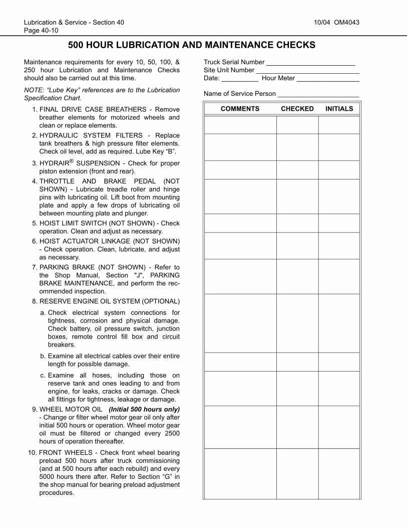
Lubrication & Service - Section 40 10/04 OM4043Page 40-10
500 HOUR LUBRICATION AND MAINTENANCE CHECKSMaintenance requirements for every 10, 50, 100, &250 hour Lubrication and Maintenance Checksshould also be carried out at this time.
NOTE: “Lube Key” references are to the LubricationSpecification Chart.
1. FINAL DRIVE CASE BREATHERS - Removebreather elements for motorized wheels andclean or replace elements.
2. HYDRAULIC SYSTEM FILTERS - Replacetank breathers & high pressure filter elements.Check oil level, add as required. Lube Key “B”.
3. HYDRAIR® SUSPENSION - Check for properpiston extension (front and rear).
4. THROTTLE AND BRAKE PEDAL (NOTSHOWN) - Lubricate treadle roller and hingepins with lubricating oil. Lift boot from mountingplate and apply a few drops of lubricating oilbetween mounting plate and plunger.
5. HOIST LIMIT SWITCH (NOT SHOWN) - Checkoperation. Clean and adjust as necessary.
6. HOIST ACTUATOR LINKAGE (NOT SHOWN)- Check operation. Clean, lubricate, and adjustas necessary.
7. PARKING BRAKE (NOT SHOWN) - Refer tothe Shop Manual, Section "J", PARKINGBRAKE MAINTENANCE, and perform the rec-ommended inspection.
8. RESERVE ENGINE OIL SYSTEM (OPTIONAL)
a. Check electrical system connections fortightness, corrosion and physical damage.Check battery, oil pressure switch, junctionboxes, remote control fill box and circuitbreakers.
b. Examine all electrical cables over their entirelength for possible damage.
c. Examine all hoses, including those onreserve tank and ones leading to and fromengine, for leaks, cracks or damage. Checkall fittings for tightness, leakage or damage.
9. WHEEL MOTOR OIL (Initial 500 hours only)- Change or filter wheel motor gear oil only afterinitial 500 hours or operation. Wheel motor gearoil must be filtered or changed every 2500hours of operation thereafter.
10. FRONT WHEELS - Check front wheel bearingpreload 500 hours after truck commissioning(and at 500 hours after each rebuild) and every5000 hours there after. Refer to Section “G” inthe shop manual for bearing preload adjustmentprocedures.
Truck Serial Number ________________________Site Unit Number ____________________________Date: __________ Hour Meter _________________
Name of Service Person ______________________
COMMENTS CHECKED INITIALS
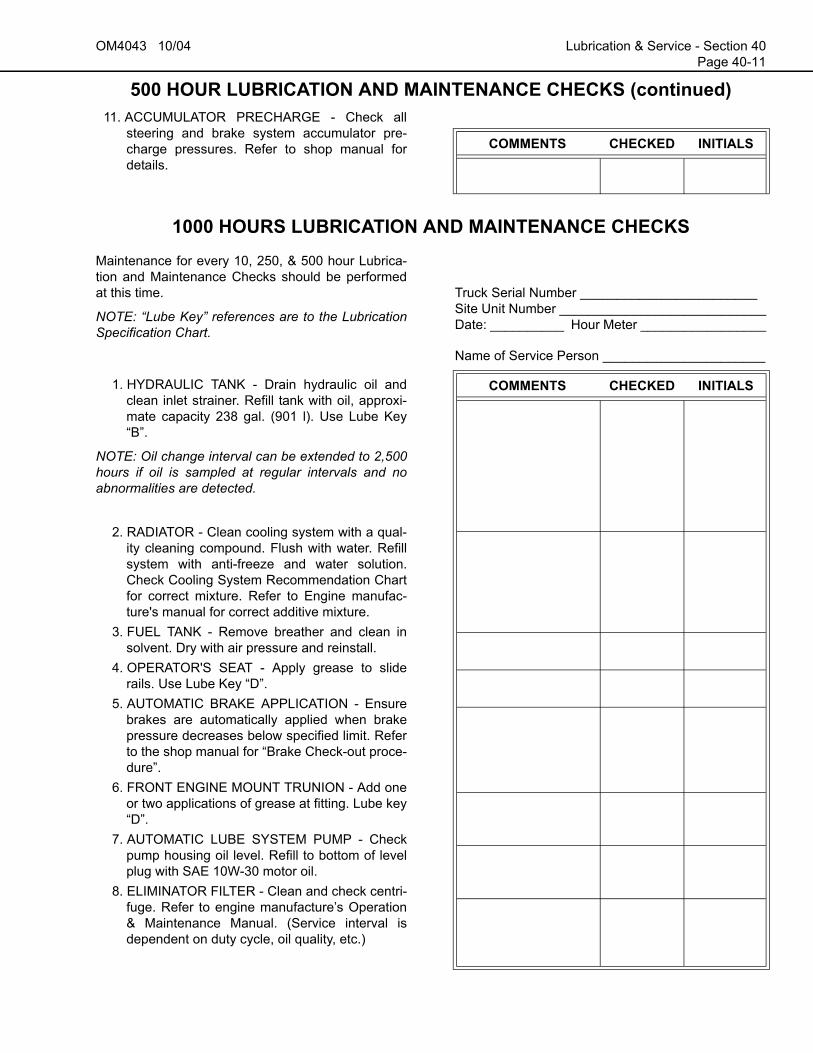
OM4043 10/04 Lubrication & Service - Section 40Page 40-11
500 HOUR LUBRICATION AND MAINTENANCE CHECKS (continued)11. ACCUMULATOR PRECHARGE - Check all
steering and brake system accumulator pre-charge pressures. Refer to shop manual fordetails.
1000 HOURS LUBRICATION AND MAINTENANCE CHECKSMaintenance for every 10, 250, & 500 hour Lubrica-tion and Maintenance Checks should be performedat this time.
NOTE: “Lube Key” references are to the LubricationSpecification Chart.
1. HYDRAULIC TANK - Drain hydraulic oil andclean inlet strainer. Refill tank with oil, approxi-mate capacity 238 gal. (901 l). Use Lube Key“B”.
NOTE: Oil change interval can be extended to 2,500hours if oil is sampled at regular intervals and noabnormalities are detected.
2. RADIATOR - Clean cooling system with a qual-ity cleaning compound. Flush with water. Refillsystem with anti-freeze and water solution.Check Cooling System Recommendation Chartfor correct mixture. Refer to Engine manufac-ture's manual for correct additive mixture.
3. FUEL TANK - Remove breather and clean insolvent. Dry with air pressure and reinstall.
4. OPERATOR'S SEAT - Apply grease to sliderails. Use Lube Key “D”.
5. AUTOMATIC BRAKE APPLICATION - Ensurebrakes are automatically applied when brakepressure decreases below specified limit. Referto the shop manual for “Brake Check-out proce-dure”.
6. FRONT ENGINE MOUNT TRUNION - Add oneor two applications of grease at fitting. Lube key“D”.
7. AUTOMATIC LUBE SYSTEM PUMP - Checkpump housing oil level. Refill to bottom of levelplug with SAE 10W-30 motor oil.
8. ELIMINATOR FILTER - Clean and check centri-fuge. Refer to engine manufacture’s Operation& Maintenance Manual. (Service interval isdependent on duty cycle, oil quality, etc.)
Truck Serial Number ________________________Site Unit Number ____________________________Date: __________ Hour Meter _________________
Name of Service Person ______________________
COMMENTS CHECKED INITIALS
COMMENTS CHECKED INITIALS
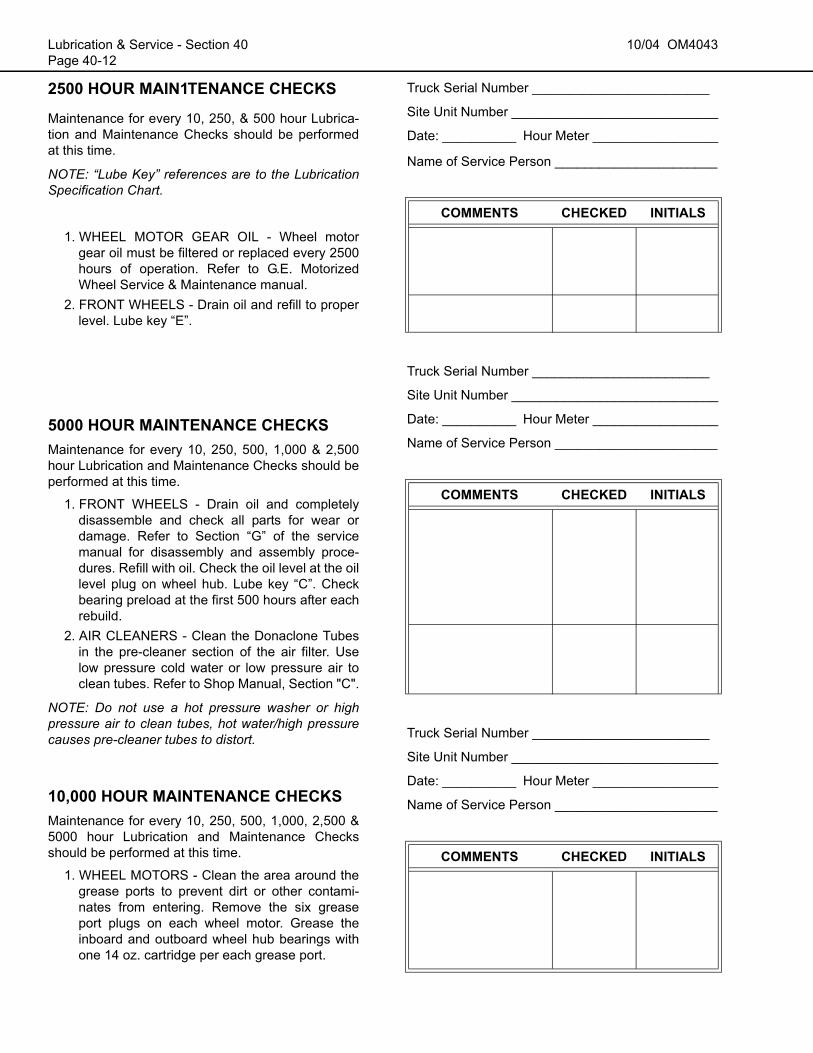
Lubrication & Service - Section 40 10/04 OM4043Page 40-12
2500 HOUR MAIN1TENANCE CHECKS
Maintenance for every 10, 250, & 500 hour Lubrica-tion and Maintenance Checks should be performedat this time.
NOTE: “Lube Key” references are to the LubricationSpecification Chart.
1. WHEEL MOTOR GEAR OIL - Wheel motorgear oil must be filtered or replaced every 2500hours of operation. Refer to G.E. MotorizedWheel Service & Maintenance manual.
2. FRONT WHEELS - Drain oil and refill to properlevel. Lube key “E”.
5000 HOUR MAINTENANCE CHECKSMaintenance for every 10, 250, 500, 1,000 & 2,500hour Lubrication and Maintenance Checks should beperformed at this time.
1. FRONT WHEELS - Drain oil and completelydisassemble and check all parts for wear ordamage. Refer to Section “G” of the servicemanual for disassembly and assembly proce-dures. Refill with oil. Check the oil level at the oillevel plug on wheel hub. Lube key “C”. Checkbearing preload at the first 500 hours after eachrebuild.
2. AIR CLEANERS - Clean the Donaclone Tubesin the pre-cleaner section of the air filter. Uselow pressure cold water or low pressure air toclean tubes. Refer to Shop Manual, Section "C".
NOTE: Do not use a hot pressure washer or highpressure air to clean tubes, hot water/high pressurecauses pre-cleaner tubes to distort.
10,000 HOUR MAINTENANCE CHECKSMaintenance for every 10, 250, 500, 1,000, 2,500 &5000 hour Lubrication and Maintenance Checksshould be performed at this time.
1. WHEEL MOTORS - Clean the area around thegrease ports to prevent dirt or other contami-nates from entering. Remove the six greaseport plugs on each wheel motor. Grease theinboard and outboard wheel hub bearings withone 14 oz. cartridge per each grease port.
Truck Serial Number ________________________
Site Unit Number ____________________________
Date: __________ Hour Meter _________________
Name of Service Person ______________________
Truck Serial Number ________________________
Site Unit Number ____________________________
Date: __________ Hour Meter _________________
Name of Service Person ______________________
Truck Serial Number ________________________
Site Unit Number ____________________________
Date: __________ Hour Meter _________________
Name of Service Person ______________________
COMMENTS CHECKED INITIALS
COMMENTS CHECKED INITIALS
COMMENTS CHECKED INITIALS
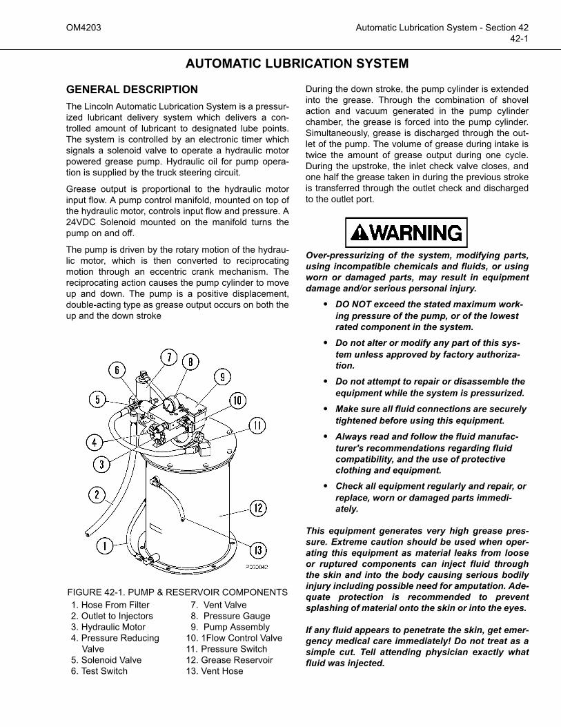
OM4203 Automatic Lubrication System - Section 4242-1
AUTOMATIC LUBRICATION SYSTEM
GENERAL DESCRIPTIONThe Lincoln Automatic Lubrication System is a pressur-ized lubricant delivery system which delivers a con-trolled amount of lubricant to designated lube points.The system is controlled by an electronic timer whichsignals a solenoid valve to operate a hydraulic motorpowered grease pump. Hydraulic oil for pump opera-tion is supplied by the truck steering circuit.
Grease output is proportional to the hydraulic motorinput flow. A pump control manifold, mounted on top ofthe hydraulic motor, controls input flow and pressure. A24VDC Solenoid mounted on the manifold turns thepump on and off.
The pump is driven by the rotary motion of the hydrau-lic motor, which is then converted to reciprocatingmotion through an eccentric crank mechanism. Thereciprocating action causes the pump cylinder to moveup and down. The pump is a positive displacement,double-acting type as grease output occurs on both theup and the down stroke
During the down stroke, the pump cylinder is extendedinto the grease. Through the combination of shovelaction and vacuum generated in the pump cylinderchamber, the grease is forced into the pump cylinder.Simultaneously, grease is discharged through the out-let of the pump. The volume of grease during intake istwice the amount of grease output during one cycle.During the upstroke, the inlet check valve closes, andone half the grease taken in during the previous strokeis transferred through the outlet check and dischargedto the outlet port.
Over-pressurizing of the system, modifying parts,using incompatible chemicals and fluids, or usingworn or damaged parts, may result in equipmentdamage and/or serious personal injury.
• DO NOT exceed the stated maximum work-ing pressure of the pump, or of the lowest rated component in the system.
• Do not alter or modify any part of this sys-tem unless approved by factory authoriza-tion.
• Do not attempt to repair or disassemble the equipment while the system is pressurized.
• Make sure all fluid connections are securely tightened before using this equipment.
• Always read and follow the fluid manufac-turer's recommendations regarding fluid compatibility, and the use of protective clothing and equipment.
• Check all equipment regularly and repair, or replace, worn or damaged parts immedi-ately.
This equipment generates very high grease pres-sure. Extreme caution should be used when oper-ating this equipment as material leaks from looseor ruptured components can inject fluid throughthe skin and into the body causing serious bodilyinjury including possible need for amputation. Ade-quate protection is recommended to preventsplashing of material onto the skin or into the eyes.
If any fluid appears to penetrate the skin, get emer-gency medical care immediately! Do not treat as asimple cut. Tell attending physician exactly whatfluid was injected.
FIGURE 42-1. PUMP & RESERVOIR COMPONENTS1. Hose From Filter2. Outlet to Injectors3. Hydraulic Motor4. Pressure Reducing
Valve5. Solenoid Valve6. Test Switch
7. Vent Valve8. Pressure Gauge9. Pump Assembly
10. 1Flow Control Valve11. Pressure Switch12. Grease Reservoir13. Vent Hose
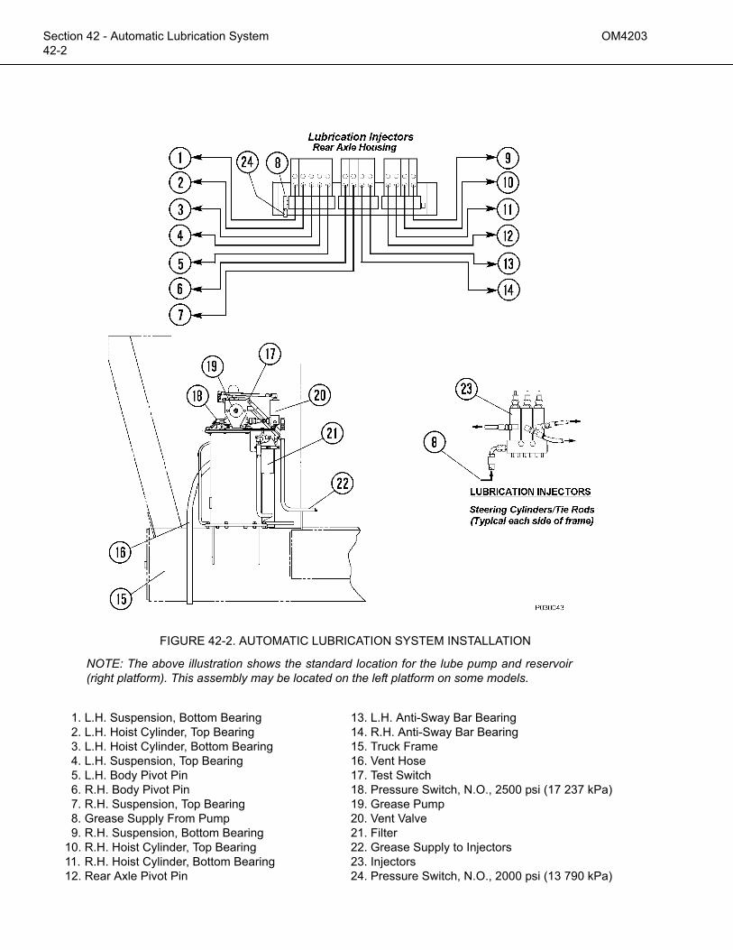
Section 42 - Automatic Lubrication System OM420342-2
FIGURE 42-2. AUTOMATIC LUBRICATION SYSTEM INSTALLATION
1. L.H. Suspension, Bottom Bearing2. L.H. Hoist Cylinder, Top Bearing3. L.H. Hoist Cylinder, Bottom Bearing4. L.H. Suspension, Top Bearing5. L.H. Body Pivot Pin6. R.H. Body Pivot Pin7. R.H. Suspension, Top Bearing8. Grease Supply From Pump9. R.H. Suspension, Bottom Bearing
10. R.H. Hoist Cylinder, Top Bearing11. R.H. Hoist Cylinder, Bottom Bearing12. Rear Axle Pivot Pin
13. L.H. Anti-Sway Bar Bearing14. R.H. Anti-Sway Bar Bearing15. Truck Frame16. Vent Hose17. Test Switch18. Pressure Switch, N.O., 2500 psi (17 237 kPa)19. Grease Pump20. Vent Valve21. Filter22. Grease Supply to Injectors23. Injectors24. Pressure Switch, N.O., 2000 psi (13 790 kPa)
NOTE: The above illustration shows the standard location for the lube pump and reservoir(right platform). This assembly may be located on the left platform on some models.
OM4203 Automatic Lubrication System - Section 4242-3
SYSTEM COMPONENTS
Filter
A filter assembly (21, Figure 42-2) mounted on thegrease reservoir filters the grease prior to refilling thereservoir from the shop supply. A bypass indicatoralerts service personnel when the filter requiresreplacement.
Hydraulic Motor and Pump
The rotary hydraulic pump (3 & 9, Figure 42-1) is a fullyhydraulically operated grease pump. An integratedpump control manifold is incorporated with the motor tocontrol input flow and pressure.
Note: The pump crankcase oil level must bemaintained to the level of the pipe plug port. Ifnecessary, refill with 10W-30 motor oil.
Hydraulic oil supply inlet pressure must notexceed 3000 psi (20 685 kPa). Exceeding the ratedpressure may result in damage to the system com-ponents and personal injury.
Grease Reservoir
The reservoir (12, Figure 42-1) has an approximatecapacity of 90 lbs. (41 kg) of grease. When the greasesupply is replenished by filling the system at the ser-vice center, the grease is passed through the filter toremove contaminants before it flows into the reservoir.
Pressure Reducing Valve
The pressure reducing valve (4, Figure 42-1), locatedon the manifold reduces the hydraulic supply pressure(from the truck steering circuit) to a suitable operatingpressure, [325-350 psi (2 240-2 415 kPa)] for thehydraulic motor used to drive the lubricant pump.
Flow Control Valve
The flow control valve (10, Figure 42-1) mounted onthe manifold, controls the amount of oil flow to thehydraulic motor. The flow control valve has been fac-tory adjusted and the setting should not be dis-turbed.
Solenoid Valve
The solenoid valve (5, Figure 42-1), when energized,allows oil to flow to the hydraulic motor.
Vent Valve
With the vent valve (7, Figure 42-1) closed, the pumpcontinues to operate until maximum grease pressure isachieved. As this occurs, the vent valve opens andallows the grease pressure to drop to 0, so the injectorscan recharge for their next output cycle.
Lubrication Cycle Timer
The solid state lubrication cycle timer (1, Figure 42-4)provides a 24 VDC timed-interval signal to energize thesolenoid valve (5, Figure 42-1), providing oil flow tooperate the grease pump motor. This timer is mountedin the Electrical Interface Cabinet.
Delay Timer
The delay timer (7, Figure 42-4), located in the Electri-cal Interface Cabinet, provides a one minute delay inthe low pressure warning lamp circuit to allow a nor-mally operating system to attain full grease systempressure without activating the warning lamp. If thesystem fails to reach 2000 psi (13 789 kPa) within thistime period, the timer will apply 24VDC to severalrelays which will illuminate the low pressure warninglamp in the overhead display. An external 604K ohmresistor determines the delay period.
Pump Cutoff Pressure Switch (N.O. 2500 psi [17237 kPa])
This pressure switch (18, Figure 42-2) de-energizesthe pump solenoid relay when the grease line pressurereaches the switch pressure setting, turning off themotor and pump.
Grease Pressure Failure Switch (N.O. 2000 psi [13789 kPa])
This pressure switch (24, Figure 42-2) monitors greasepressure in the injector bank on the rear axle housing.If the proper pressure is not sensed within 60 seconds(switch contacts do not close), several relays energize,actuating a warning lamp circuit to notify the operator aproblem exists in the lube system.
Pressure Gauge
The pressure gauge (8, Figure 42-1) monitors hydrau-lic oil pressure to the inlet of the hydraulic motor.
Injectors
Each injector (23, Figure 42-2) delivers a controlledamount of pressurized lubricant to a designated lubepoint. Refer to Figure 42-2 for locations.
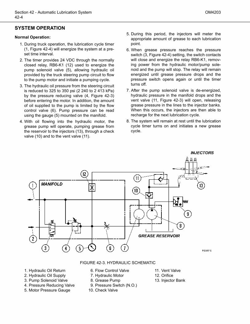
Section 42 - Automatic Lubrication System OM420342-4
SYSTEM OPERATION
Normal Operation:1. During truck operation, the lubrication cycle timer
(1, Figure 42-4) will energize the system at a pre-set time interval.
2. The timer provides 24 VDC through the normallyclosed relay, RB6-K1 (12) used to energize thepump solenoid valve (5), allowing hydraulic oilprovided by the truck steering pump circuit to flowto the pump motor and initiate a pumping cycle.
3. The hydraulic oil pressure from the steering circuitis reduced to 325 to 350 psi (2 240 to 2 413 kPa)by the pressure reducing valve (4, Figure 42-3)before entering the motor. In addition, the amountof oil supplied to the pump is limited by the flowcontrol valve (6). Pump pressure can be readusing the gauge (5) mounted on the manifold.
4. With oil flowing into the hydraulic motor, thegrease pump will operate, pumping grease fromthe reservoir to the injectors (13), through a checkvalve (10) and to the vent valve (11).
5. During this period, the injectors will meter theappropriate amount of grease to each lubricationpoint.
6. When grease pressure reaches the pressureswitch (3, Figure 42-4) setting, the switch contactswill close and energize the relay RB6-K1, remov-ing power from the hydraulic motor/pump sole-noid and the pump will stop. The relay will remainenergized until grease pressure drops and thepressure switch opens again or until the timerturns off.
7. After the pump solenoid valve is de-energized,hydraulic pressure in the manifold drops and thevent valve (11, Figure 42-3) will open, releasinggrease pressure in the lines to the injector banks.When this occurs, the injectors are then able torecharge for the next lubrication cycle.
8. The system will remain at rest until the lubricationcycle timer turns on and initiates a new greasecycle.
FIGURE 42-3. HYDRAULIC SCHEMATIC
1. Hydraulic Oil Return2. Hydraulic Oil Supply3. Pump Solenoid Valve4. Pressure Reducing Valve5. Motor Pressure Gauge
6. Flow Control Valve7. Hydraulic Motor8. Grease Pump9. Pressure Switch (N.O.)
10. Check Valve
11. Vent Valve12. Orifice13. Injector Bank
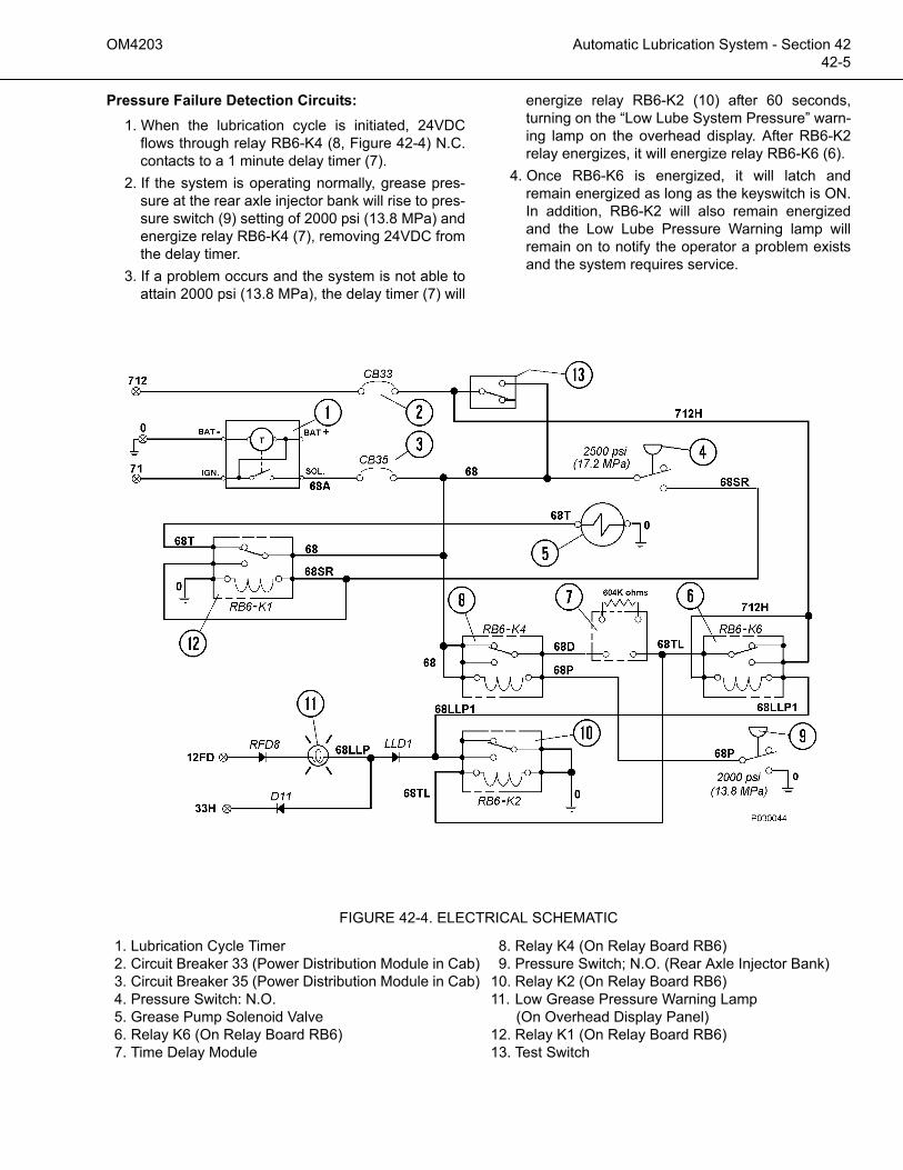
OM4203 Automatic Lubrication System - Section 4242-5
Pressure Failure Detection Circuits:1. When the lubrication cycle is initiated, 24VDC
flows through relay RB6-K4 (8, Figure 42-4) N.C.contacts to a 1 minute delay timer (7).
2. If the system is operating normally, grease pres-sure at the rear axle injector bank will rise to pres-sure switch (9) setting of 2000 psi (13.8 MPa) andenergize relay RB6-K4 (7), removing 24VDC fromthe delay timer.
3. If a problem occurs and the system is not able toattain 2000 psi (13.8 MPa), the delay timer (7) will
energize relay RB6-K2 (10) after 60 seconds,turning on the “Low Lube System Pressure” warn-ing lamp on the overhead display. After RB6-K2relay energizes, it will energize relay RB6-K6 (6).
4. Once RB6-K6 is energized, it will latch andremain energized as long as the keyswitch is ON.In addition, RB6-K2 will also remain energizedand the Low Lube Pressure Warning lamp willremain on to notify the operator a problem existsand the system requires service.
FIGURE 42-4. ELECTRICAL SCHEMATIC
1. Lubrication Cycle Timer2. Circuit Breaker 33 (Power Distribution Module in Cab)3. Circuit Breaker 35 (Power Distribution Module in Cab)4. Pressure Switch: N.O.5. Grease Pump Solenoid Valve 6. Relay K6 (On Relay Board RB6)7. Time Delay Module
8. Relay K4 (On Relay Board RB6)9. Pressure Switch; N.O. (Rear Axle Injector Bank)
10. Relay K2 (On Relay Board RB6)11. Low Grease Pressure Warning Lamp
(On Overhead Display Panel)12. Relay K1 (On Relay Board RB6)13. Test Switch
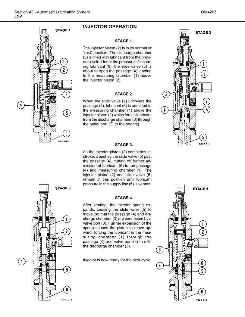
Section 42 - Automatic Lubrication System OM420342-6
GENERAL INSTRUCTIONS
LUBRICANT REQUIRED FOR SYSTEMGrease requirements will dependon ambient temperatures encoun-tered during truck operation:
• Above 90°F (32°C) - Use NLGI No. 2 multipurpose grease (MPG).
• -25° to 90°F (-32° to 32°C) - Use NLGI No. 1 multipur-pose grease (MPG).
• Below -25°F (-32°C) - Refer to local supplier for extreme cold weather lubricant requirements.
INJECTOR OPERATION
STAGE 1.
The injector piston (2) is in its normal or“rest” position. The discharge chamber(3) is filled with lubricant from the previ-ous cycle. Under the pressure of incom-ing lubricant (6), the slide valve (5) isabout to open the passage (4) leadingto the measuring chamber (1) abovethe injector piston (2).
STAGE 2.
When the slide valve (5) uncovers thepassage (4), lubricant (6) is admitted tothe measuring chamber (1) above theinjector piston (2) which forces lubricantfrom the discharge chamber (3) throughthe outlet port (7) to the bearing.
STAGE 3.
As the injector piston (2) completes itsstroke, it pushes the slide valve (5) pastthe passage (4), cutting off further ad-mission of lubricant (6) to the passage(4) and measuring chamber (1). Theinjector piston (2) and slide valve (5)remain in this position until lubricantpressure in the supply line (6) is vented.
STAGE 4.
After venting, the injector spring ex-pands, causing the slide valve (5) tomove, so that the passage (4) and dis-charge chamber (3) are connected by avalve port (8). Further expansion of thespring causes the piston to move up-ward, forcing the lubricant in the mea-suring chamber (1) through thepassage (4) and valve port (8) to refillthe discharge chamber (3).
Injector is now ready for the next cycle.
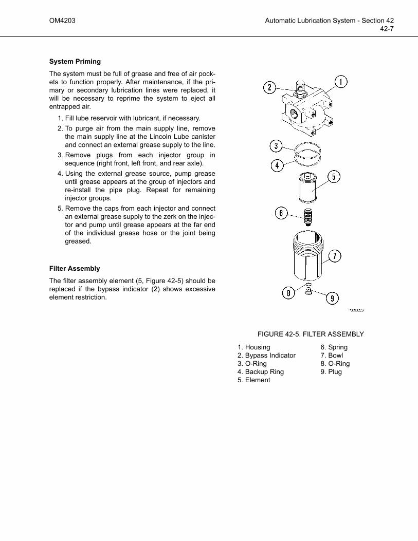
OM4203 Automatic Lubrication System - Section 4242-7
System Priming
The system must be full of grease and free of air pock-ets to function properly. After maintenance, if the pri-mary or secondary lubrication lines were replaced, itwill be necessary to reprime the system to eject allentrapped air.
1. Fill lube reservoir with lubricant, if necessary.2. To purge air from the main supply line, remove
the main supply line at the Lincoln Lube canisterand connect an external grease supply to the line.
3. Remove plugs from each injector group insequence (right front, left front, and rear axle).
4. Using the external grease source, pump greaseuntil grease appears at the group of injectors andre-install the pipe plug. Repeat for remaininginjector groups.
5. Remove the caps from each injector and connectan external grease supply to the zerk on the injec-tor and pump until grease appears at the far endof the individual grease hose or the joint beinggreased.
Filter Assembly
The filter assembly element (5, Figure 42-5) should bereplaced if the bypass indicator (2) shows excessiveelement restriction.
FIGURE 42-5. FILTER ASSEMBLY
1. Housing2. Bypass Indicator3. O-Ring4. Backup Ring5. Element
6. Spring7. Bowl8. O-Ring9. Plug
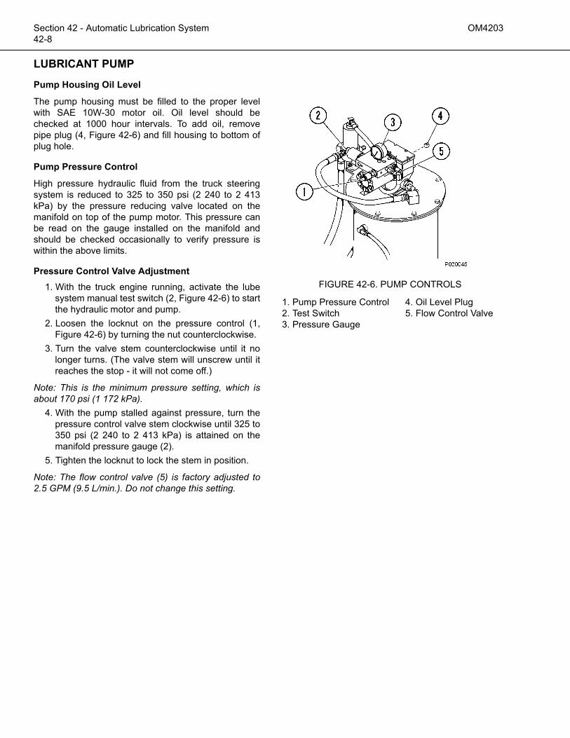
Section 42 - Automatic Lubrication System OM420342-8
LUBRICANT PUMP
Pump Housing Oil Level
The pump housing must be filled to the proper levelwith SAE 10W-30 motor oil. Oil level should bechecked at 1000 hour intervals. To add oil, removepipe plug (4, Figure 42-6) and fill housing to bottom ofplug hole.
Pump Pressure Control
High pressure hydraulic fluid from the truck steeringsystem is reduced to 325 to 350 psi (2 240 to 2 413kPa) by the pressure reducing valve located on themanifold on top of the pump motor. This pressure canbe read on the gauge installed on the manifold andshould be checked occasionally to verify pressure iswithin the above limits.
Pressure Control Valve Adjustment1. With the truck engine running, activate the lube
system manual test switch (2, Figure 42-6) to startthe hydraulic motor and pump.
2. Loosen the locknut on the pressure control (1,Figure 42-6) by turning the nut counterclockwise.
3. Turn the valve stem counterclockwise until it nolonger turns. (The valve stem will unscrew until itreaches the stop - it will not come off.)
Note: This is the minimum pressure setting, which isabout 170 psi (1 172 kPa).
4. With the pump stalled against pressure, turn thepressure control valve stem clockwise until 325 to350 psi (2 240 to 2 413 kPa) is attained on themanifold pressure gauge (2).
5. Tighten the locknut to lock the stem in position.
Note: The flow control valve (5) is factory adjusted to2.5 GPM (9.5 L/min.). Do not change this setting.
FIGURE 42-6. PUMP CONTROLS
1. Pump Pressure Control2. Test Switch3. Pressure Gauge
4. Oil Level Plug5. Flow Control Valve
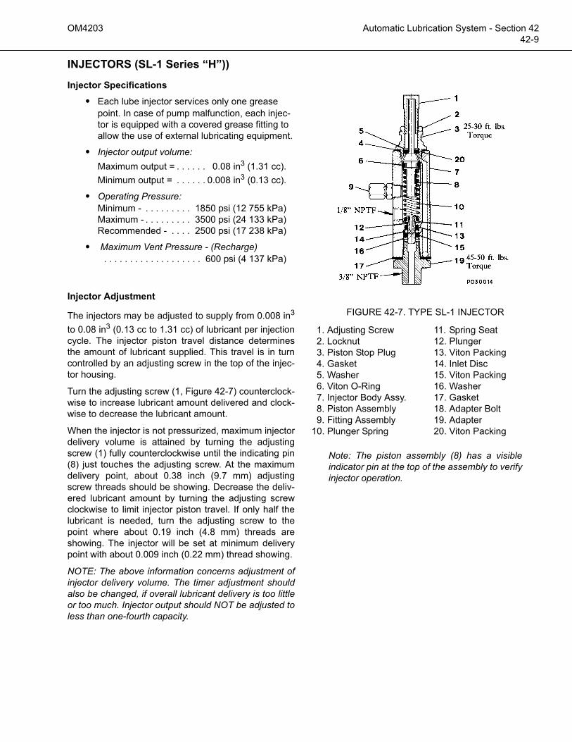
OM4203 Automatic Lubrication System - Section 4242-9
INJECTORS (SL-1 Series “H”))
Injector Specifications• Each lube injector services only one grease
point. In case of pump malfunction, each injec-tor is equipped with a covered grease fitting to allow the use of external lubricating equipment.
• Injector output volume: Maximum output = . . . . . . 0.08 in3 (1.31 cc).Minimum output = . . . . . . 0.008 in3 (0.13 cc).
• Operating Pressure:Minimum - . . . . . . . . . 1850 psi (12 755 kPa)Maximum - . . . . . . . . . 3500 psi (24 133 kPa)Recommended - . . . . 2500 psi (17 238 kPa)
• Maximum Vent Pressure - (Recharge) . . . . . . . . . . . . . . . . . . . 600 psi (4 137 kPa)
Injector Adjustment
The injectors may be adjusted to supply from 0.008 in3
to 0.08 in3 (0.13 cc to 1.31 cc) of lubricant per injectioncycle. The injector piston travel distance determinesthe amount of lubricant supplied. This travel is in turncontrolled by an adjusting screw in the top of the injec-tor housing.
Turn the adjusting screw (1, Figure 42-7) counterclock-wise to increase lubricant amount delivered and clock-wise to decrease the lubricant amount.
When the injector is not pressurized, maximum injectordelivery volume is attained by turning the adjustingscrew (1) fully counterclockwise until the indicating pin(8) just touches the adjusting screw. At the maximumdelivery point, about 0.38 inch (9.7 mm) adjustingscrew threads should be showing. Decrease the deliv-ered lubricant amount by turning the adjusting screwclockwise to limit injector piston travel. If only half thelubricant is needed, turn the adjusting screw to thepoint where about 0.19 inch (4.8 mm) threads areshowing. The injector will be set at minimum deliverypoint with about 0.009 inch (0.22 mm) thread showing.
NOTE: The above information concerns adjustment ofinjector delivery volume. The timer adjustment shouldalso be changed, if overall lubricant delivery is too littleor too much. Injector output should NOT be adjusted toless than one-fourth capacity.
FIGURE 42-7. TYPE SL-1 INJECTOR
1. Adjusting Screw2. Locknut3. Piston Stop Plug4. Gasket5. Washer6. Viton O-Ring7. Injector Body Assy.8. Piston Assembly9. Fitting Assembly
10. Plunger Spring
11. Spring Seat12. Plunger13. Viton Packing14. Inlet Disc15. Viton Packing16. Washer17. Gasket18. Adapter Bolt19. Adapter20. Viton Packing
Note: The piston assembly (8) has a visibleindicator pin at the top of the assembly to verifyinjector operation.
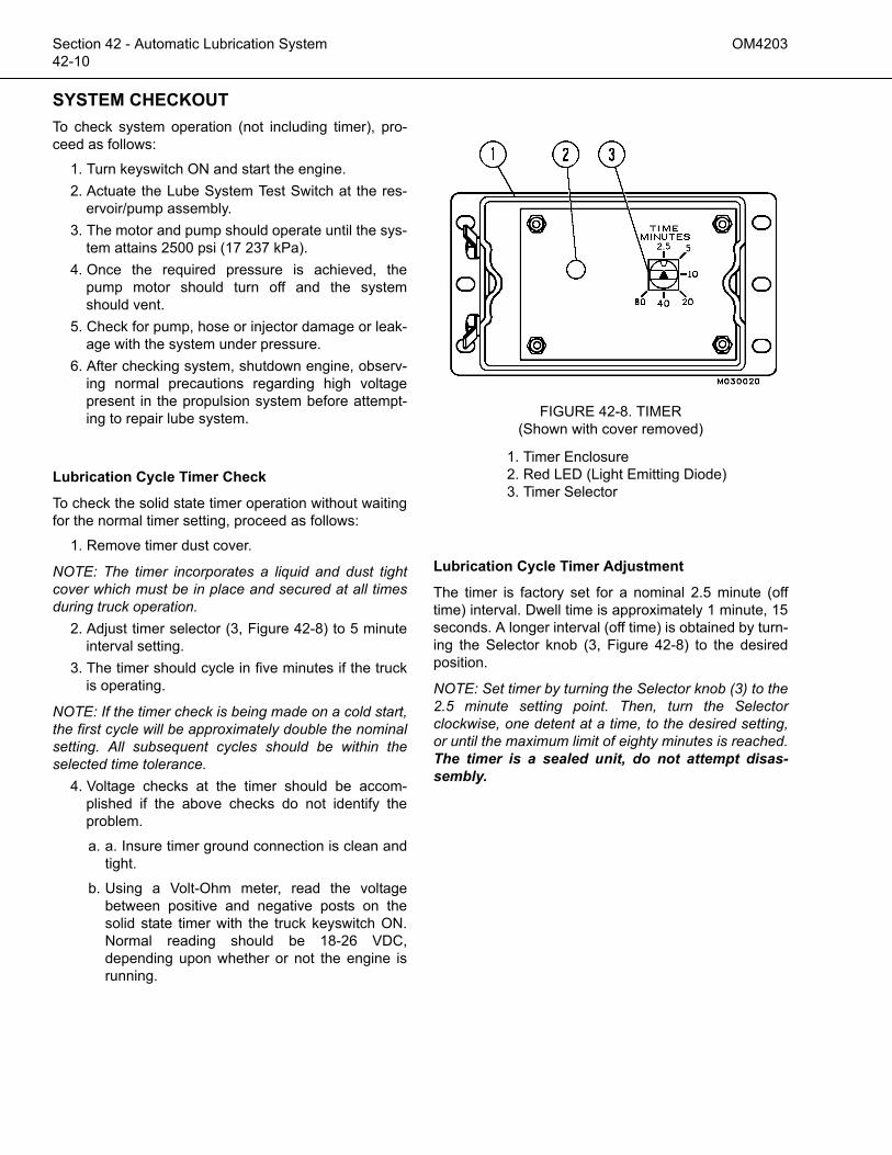
Section 42 - Automatic Lubrication System OM420342-10
SYSTEM CHECKOUTTo check system operation (not including timer), pro-ceed as follows:
1. Turn keyswitch ON and start the engine. 2. Actuate the Lube System Test Switch at the res-
ervoir/pump assembly.3. The motor and pump should operate until the sys-
tem attains 2500 psi (17 237 kPa). 4. Once the required pressure is achieved, the
pump motor should turn off and the systemshould vent.
5. Check for pump, hose or injector damage or leak-age with the system under pressure.
6. After checking system, shutdown engine, observ-ing normal precautions regarding high voltagepresent in the propulsion system before attempt-ing to repair lube system.
Lubrication Cycle Timer Check
To check the solid state timer operation without waitingfor the normal timer setting, proceed as follows:
1. Remove timer dust cover.
NOTE: The timer incorporates a liquid and dust tightcover which must be in place and secured at all timesduring truck operation.
2. Adjust timer selector (3, Figure 42-8) to 5 minuteinterval setting.
3. The timer should cycle in five minutes if the truckis operating.
NOTE: If the timer check is being made on a cold start,the first cycle will be approximately double the nominalsetting. All subsequent cycles should be within theselected time tolerance.
4. Voltage checks at the timer should be accom-plished if the above checks do not identify theproblem.
a. a. Insure timer ground connection is clean andtight.
b. Using a Volt-Ohm meter, read the voltagebetween positive and negative posts on thesolid state timer with the truck keyswitch ON.Normal reading should be 18-26 VDC,depending upon whether or not the engine isrunning.
Lubrication Cycle Timer Adjustment
The timer is factory set for a nominal 2.5 minute (offtime) interval. Dwell time is approximately 1 minute, 15seconds. A longer interval (off time) is obtained by turn-ing the Selector knob (3, Figure 42-8) to the desiredposition.
NOTE: Set timer by turning the Selector knob (3) to the2.5 minute setting point. Then, turn the Selectorclockwise, one detent at a time, to the desired setting,or until the maximum limit of eighty minutes is reached.The timer is a sealed unit, do not attempt disas-sembly.
FIGURE 42-8. TIMER(Shown with cover removed)
1. Timer Enclosure2. Red LED (Light Emitting Diode)3. Timer Selector
OM4203 Automatic Lubrication System - Section 4242-11
SYSTEM TROUBLESHOOTING CHARTIf the following procedures do not correct the problem, contact a factory authorized service center.
TROUBLE POSSIBLE CAUSES SUGGESTED CORRECTIVE ACTION
Pump Does Not Operate
Lube system not grounded.
Electrical power loss.
Timer malfunction.Solenoid valve malfunctioning.Relay malfunctioningMotor or pump malfunction.
Correct grounding connections to pump assembly and truck chassis.Locate cause of power loss and repair. 24 VDC power required. Be sure keyswitch is ON.Replace timer assemblyReplace the solenoid valve assemblyReplace relayRepair or replace motor and/or pump assembly. (Refer to Service Manual for rebuild instructions.)
NOTE: On initial startup of the lube system, the timing capacitor will not contain a charge, therefore the first timing cycle will be about double in length compared to the normal interval. Subsequent timer cycles should be as specified.
Pump Will Not PrimeLow lubricant supply. Dirt in reservoir, pump inlet clogged, filter
clogged.
Pump Will Not Build Pressure
Air trapped in lubricant supply line.Lubricant supply line leaking.
Vent valve leaking.Pump worn or scored.
Prime system to remove trapped air.Check lines and connections to repair leakage.Clean or replace vent valve.Repair or replace pump assembly. (Refer to Service Manual for rebuild instructions.)
Injector Indicator Stem Does Not Operate
NOTE: Normally, during operation, the injector indicator stem will move into the body of the injector when pressure builds properly. When the system vents (pres-sure release) the indicator stem will again move out into the adjusting yoke.Malfunctioning injector - usually indicated by the pump building pressure and then venting.All injectors inoperative - pump build up not sufficient to cycle injec-tors.
Replace individual injector assembly.
Service and/or replace pump assembly. (Refer to Service Manual for rebuild instructions.)
Pressure Gauge Does Not Register Pressure
No system pressure to the pump motor.No 24 VDC signal at pump sole-noid.Pressure reducing valve set too low.24V Relay (RB6, K6) may be defec-tive.
Check hydraulic hose from steering sys-tem.Determine problem in 24 VDC electric system.Refer to “Pressure Control Valve Adjust-ment”.Replace relay.
Section 42 - Automatic Lubrication System OM420342-12
Pump Pressure Builds Very Slowly Or Not At All
No signal at 24V relay.Pressure switch may be defectivePressure reducing valve may be set too low.Grease viscosity may be too high for temperature at which pump is operating.Pump inlet check or outlet check may have foreign matter trapped causing leakage.Lubricant supply line leaks or is bro-ken.Insufficient hydraulic oil supply.
Check Timer.Replace pressure switch.Refer to “Pressure Control Valve Adjust-ment”.Replace grease with a lower viscosity lubricant.
Remove, inspect and clean, if neces-sary.Inspect sealing surfaces between checks. Replace if rough or pitted.Repair lubricant supply line
Check oil pressure and flow to motor.
24VDC Timer Not Operating
Timer BAT (-) connection is not on grounded member.Timer IGN terminal connection not on circuit continuously to circuit 71 during operation of vehicle.
Loose wire connections at any of the timer terminals.
Connect to good ground.
Verify IGN terminal and circuit 71 connec-tion.
Secure wire connections.
Timer Stays Timed Out
Commutation failure in timer caused by damaged component.Output relay contacts welded shut caused by extended short to ground.
Replace Timer
Replace Timer.
Timer Turns On At Intervals Two (2) To Ten (10) Times More Often Than Set Time Interval
Electrical noise is being introduced into the power supply to the timer overcoming suppressor capacitor causing uncontrolled turn-on of its output relay.
IMPORTANT: In some instances, elec-trical noise may be generated into vehicle electrical system which may cause timer to turn on at random inter-vals, independent of timer setting. If this occurs, a 250 to 1,000 MFD capacitor rated 150 to 350 VDC should be added across BAT (+) and BAT (-) terminals to suppress this noise and improve timer performance.
Timer Turns On At Intervals Faster Than
Allowable Tolerances Of Settings
Timer out of adjustment or dam-aged component.
Refer to “Timer Adjustment” and re-adjust timer or replace timer.
TROUBLE POSSIBLE CAUSES SUGGESTED CORRECTIVE ACTION
OM4203 Automatic Lubrication System - Section 4242-13
PREVENTATIVE MAINTENANCE PROCEDURESThe following maintenance procedures should be usedto insure proper system operation.
Daily Lubrication System Inspection1. Check grease reservoir level.
Inspect grease level height after each shift ofoperation. Grease usage should be consistentfrom day-to-day operations.
• Lack of lubricant usage would indicate an inop-erative system. Excessive usage would indicate a broken supply line.
2. Check filter bypass indicator when filling reser-voir. Replace element if bypassing.
3. Check all grease feed line hoses from the SL-1Injectors to the lubrication points.
a. Repair or replace all damaged feed line hoses.
b. Make sure that all air is purged and all newfeed line hoses are filled with grease beforesending the truck back into service.
4. Inspect key lubrication points for a bead of lubri-cant around seal. If a lubrication point appearsdry, troubleshoot and repair problem.
250 Hour Inspection1. Check all grease feed line hoses from the SL-1
Injectors to the lubrication points (see, Figure 42-2).
a. Repair or replace all worn / broken feed linehoses.
b. Make sure that all air is purged and all newfeed line hoses are filled with grease beforesending the truck back into service.
2. Check all grease supply line hoses from the pumpto the SL-1 injectors.
a. Repair or replace all worn / broken supplylines.
b. Make sure that all air is purged and all newsupply line hoses are filled with grease beforesending the truck back into service.
3. Check grease reservoir level.
a. Fill reservoir if low. Check filter bypass indica-tor when filling reservoir. Replace element ifbypassing.
b. Check reservoir for contaminants. Clean, ifrequired.
c. Check that all filler plugs, covers and breathervents on the reservoir are intact and free ofcontaminants.
4. Inspect all bearing points for a bead of lubricantaround the bearing seal.It is good practice to manually lube each bearingpoint at the grease fitting provided on each Injec-tor. This will indicate if there are any frozen orplugged bearings, and will help flush the bearingsof contaminants.
5. System Checkout
a. Remove all SL-1 injector cover caps to allowvisual inspection of the injector cycle indicatorpins during system operation.
b. Start truck engine.
c. Actuate the lube system manual test switch(17, Figure 42-2). The hydraulic motor andgrease pump should operate.
d. With the grease under pressure, check eachSL-1 injector assembly. The cycle indicator pin should be retractedinside the injector body.
e. When the system attains 2500 psi (17 237kPa), the pump should shut off and the pres-sure in the system should drop to zero, ventingback to the grease reservoir.
f. With the system vented, check all of the SL-1injector indicator pins; all of the pins should bevisible. Replace or repair injectors, if defective.
g. Reinstall all injector cover caps.
h. Check timer operation.
Note: With engine running, lube system should activatewithin 5 minutes. The system should build 2000 to2500 psi within 25-40 seconds.
i. If the system is working properly, the machineis ready for operation.
j. If the system is malfunctioning, refer to thetroubleshooting chart.
1000 Hour Inspection1. Check pump housing oil level. Refill to bottom of
level plug with SAE 10W-30 motor oil if necessary

Section 42 - Automatic Lubrication System OM420342-14
NOTES:
OM5036 10/04 Specifications - Section 5Page 50-1
TRUCK COMPONENT DESCRIPTIONThe KOMATSU Model 830E Truck is an electric drive,off-highway, rear dump truck whose gross vehicleweight is 850,000 lbs. (385 553 kg) (240 - 255 ton nom-inal payload).
ENGINE This Model 830E Truck is powered by a KomatsuSDA16V160 diesel engine rated at 2500 hp (1865 kW)@ 1900 RPM. The radiator, engine, alternator, andblower are mounted on a separate subframe to providefast, easy removal and installation of the power mod-ule.
ALTERNATOR (G.E. GTA-26)The alternator is mounted in-line with the engine. Thealternating current (AC) output of the alternator is recti-fied to direct current (DC) and sent to the wheelmounted DC drive traction motors.
BLOWERThe dual impeller, in-line blower supplies cooling air forthe alternator, rectifiers, and both traction motors. Theair is exhausted to atmosphere through the wheelmotors.
WHEEL MOTORSTraction motors located within each rear wheel struc-ture receive electrical energy from the alternator. Thetwo traction motors convert electrical energy back tomechanical energy through built-in gear trains withinthe wheel structure. The direction of the drive motors iscontrolled by a forward or reverse hand selector switchlocated on a console in the cab to the right side of theoperator.
POWER STEERINGThe Komatsu truck is equipped with a full time powersteering system which provides positive steering con-trol with a minimum of effort by the operator. The sys-tem includes a nitrogen-charged accumulator whichautomatically provides emergency power if the steeringhydraulic pressure is reduced below an establishedminimum.
OPERATOR’S CABThe Operator’s Cab has been engineered for operatorcomfort and to allow for efficient and safe operation ofthe truck. The cab contains an integrated ROPS and isfully insulated to reduce noise and vibration. The tintedsafety-glass windshield and side windows provideexcellent visibility. The seat is a comfortable, adjust-able suspension seat, the steering wheel provides tiltand telescoping adjustments and controls are mountedwithin easy reach of the operator. The instrument panelprovides the operator with instruments and gauges thatare necessary to control and monitor the truck’s operat-ing systems and is marked with international symbolsfor easy identification of functions.
DYNAMIC RETARDINGDynamic retarding is used to slow the truck during nor-mal operation or control speed coming down a grade.The dynamic retarding ability of the DC electric systemis controlled by the operator by depressing the footoperated retarder pedal and/or setting the RSC(Retarder Speed Control) on the instrument panel.Dynamic Retarding is automatically activated if truckexceeds the overspeed setting.
BRAKE SYSTEM The braking system consists of an all hydraulic actua-tion system. Depressing the brake pedal actuateswheel-speed single disc front brakes and armature-speed dual disc rear brakes. The brakes can also beactivated by operating a switch on the instrumentpanel. The brakes will be applied automatically if sys-tem pressure decreases below a preset minimum.
SUSPENSION HYDRAIR® II suspension cylinders located at eachwheel provide a smooth and comfortable ride for theoperator and dampens shock loads to the chassis dur-ing loading.
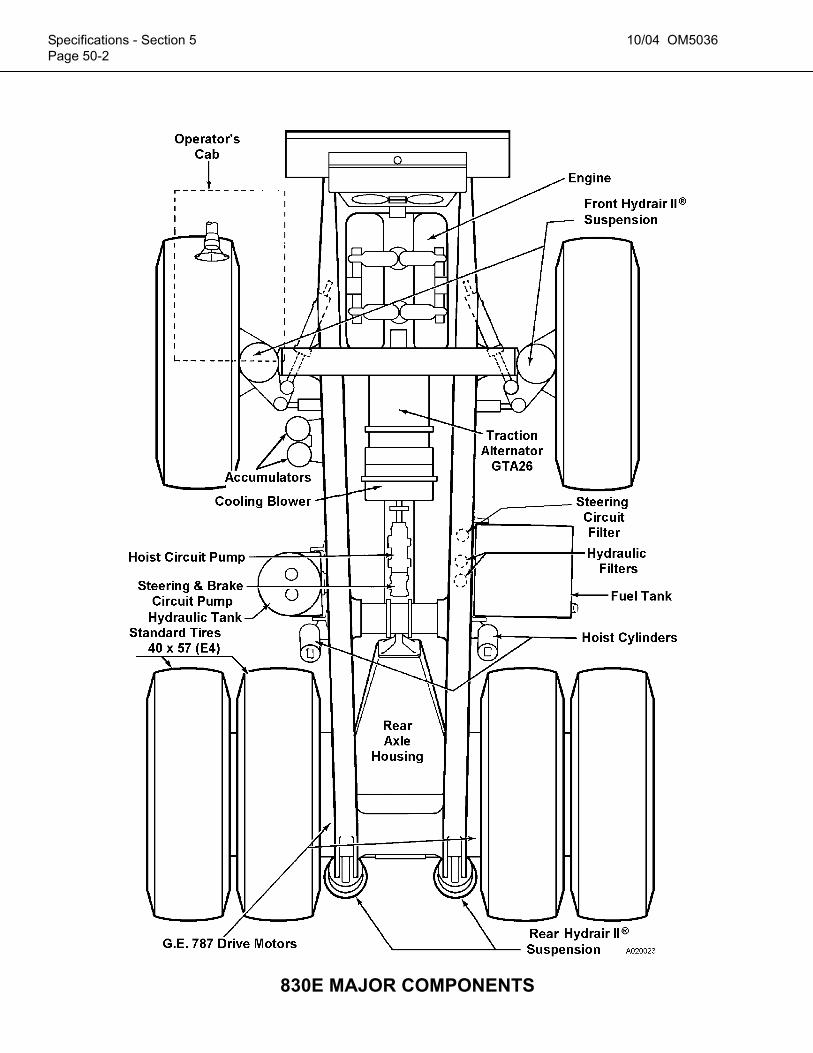
Specifications - Section 5 10/04 OM5036Page 50-2
830E MAJOR COMPONENTS
OM5036 10/04 Specifications - Section 5Page 50-3
SPECIFICATIONSThese specifications are for the standard Komatsu830E Truck. Customer Options may change this listing.
ENGINE Komatsu SDA16V160 (optional SSDA16V160)No. of Cylinders . . . . . . . . . . . . . . . . . . . . . . . . . . . . .16Operating Cycle. . . . . . . . . . . . . . . . . . . . . . . . 4-StrokeRated Brake HP. . . .2500 HP (1865 kW) @ 1900 RPMFlywheel HP . . . . . .2360 HP (1761 kW) @ 1900 RPM
Weight* (Wet) . . . . . . . . . 21,182 pounds (9 608 kg)
* Weight does not include Radiator, Sub-frame, orAlternator
ELECTRIC DRIVE SYSTEM - STATEX III(AC/DC Current)Alternator . . . . . . . . . . . . . . General Electric GTA - 26Dual Impeller, In-Line Blower. . 9000 cfm (255 m3/min)Motorized Wheels . . . . . . . . . . . . General Electric 787
Ratio . . . . . . . . . . . . . . . . . . . . . . . . . . . . . 31.875:1Maximum Speed* . . . . . . . . . 30.3 MPH (48.8 km/h)(*w/40.00-57 Tires and 31.875:1 gear train)
DYNAMIC RETARDINGExtended Range Retarding with fully blown 14-Resistorgrids and reverse retarding standard equipment.Maximum Rating . . . . . . . . . . . . . . 4000 HP (2983 kW)
TIRESRock Service, Deep Tread. . . . . . . . . . (E-4) TubelessStandard Tire . . . . . . . . . . . . 40.00 - 57, 68 Ply Rating
(w/787 Wheelmotor)Separable Tire Rims *5 Piece New Generation™ Rims *
Rims* are interchangeable with different positions onthe truck, but due to improved design for greater loadsupport, rims are not interchangeable with other manu-facturer’s rims.
Rim Size:29 in. (737 mm) X 57 in. (1448 mm) X 6 in. (152 mm)
24 VDC ELECTRIC SYSTEMBatteries . . . . Four 12 Volt Batteries in Series/Parallel. . . . . 220 Ampere-Hour Capacity w/Disconnect SwitchAlternator . . . . . . . . . . . . 24 Volt, 260 Ampere OutputLighting . . . . . . . . . . . . . . . . . . . . . . . . . . . . . . . 24 VoltCranking Motors . . . . . . . . . . . . . . . . . . . . . (2) 24 Volt
SERVICE CAPACITIES. . . . . . . . . . . . . . . . . . . . . . U.S. Gallons . . . . . (Liters)Crankcase * . . . . . . . . . . . . . . . . . . 74.0 . . . . . . 280.0 * Includes Lube Oil FiltersCooling System . . . . . . . . . . . . . . . . 150 . . . . . . . .568Fuel . . . . . . . . . . . . . . . . . . . . . . . . 1200 . . . . . . .4542Hydraulic System. . . . . . . . . . . . . . . 250 . . . . . . . 946Hydraulic Tank . . . . . . . . . . . . . . . . . 238 . . . . . . . .901Wheel Motor Gear Box (each) . . . . . 10.5 . . . . . . . 39.7
HYDRAULIC SYSTEMS*PumpsHoist . . . . . . . . . . . . . . . . . . . . . . Tandem Gear Pump. . . . . . . . . . . . .225 GPM (851 lpm.) @ 1900 RPM and . . . . . . . . . . . . . . . . . . . . . . . . . .2,500 psi (17 240 kPa)Steering & Brake . . . . Piston, Pressure Compensating. . . . . . . . . . . . . . 65 GPM (246 lpm) @ 1900 RPM and. . . . . . . . . . . . . . . . . . . . . . . . . .2,750 psi (18 961 kPa)
System Relief PressuresHoist . . . . . . . . . . . . . . . . . . . . .2,500 psi (17 240 kPa)Steering/Brakes . . . . . . . . . . . . .4,000 psi (27 580 kPa)Hoist Cylinders (2) . . . . . . . . . . . . . . . . . . . . . . 3-StageTank (Vertical/Cylindrical) . . . . . . . . . Non-PressurizedFiltration. . . Remote-mounted, Replaceable, Elements
Suction. . . . . . . . . . . . . .Single, Full Flow, 100 MeshHoist & Steering . . . . . . . . . . . . . . . . . . . . . . . . . . . .
. . . . . . . . . . . . . . . . . . . . . . . . . Full Flow, Dual In-Line,
. . . . . . . . . . . . . . . High Pressure Beta 12 Rating =200
*With Quick Disconnects for powering disabled truckand system diagnostics.
STEERING (w / Accumulators)Turning Circle - Front Wheel Track . . . . 93 ft. (28.4 m)Full Time Power Steering. . . . . . . . . . . Twin Cylinders
Automatic Emergency Steering . . . . . . . . . Standard
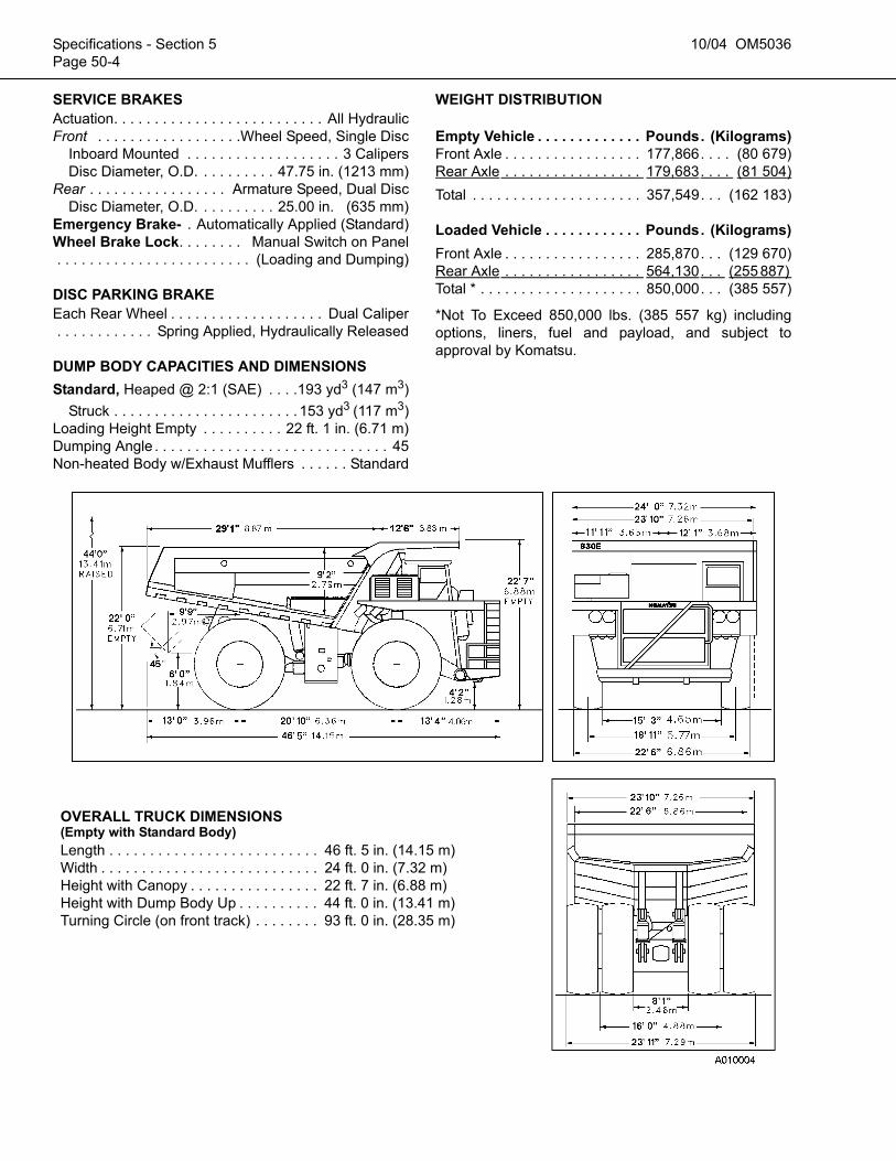
Specifications - Section 5 10/04 OM5036Page 50-4
SERVICE BRAKESActuation. . . . . . . . . . . . . . . . . . . . . . . . . . All HydraulicFront . . . . . . . . . . . . . . . . . .Wheel Speed, Single Disc
Inboard Mounted . . . . . . . . . . . . . . . . . . . 3 CalipersDisc Diameter, O.D. . . . . . . . . . 47.75 in. (1213 mm)
Rear . . . . . . . . . . . . . . . . . Armature Speed, Dual DiscDisc Diameter, O.D. . . . . . . . . . 25.00 in. (635 mm)
Emergency Brake- . Automatically Applied (Standard)Wheel Brake Lock. . . . . . . . Manual Switch on Panel . . . . . . . . . . . . . . . . . . . . . . . . (Loading and Dumping)
DISC PARKING BRAKEEach Rear Wheel . . . . . . . . . . . . . . . . . . . Dual Caliper . . . . . . . . . . . . Spring Applied, Hydraulically Released
DUMP BODY CAPACITIES AND DIMENSIONSStandard, Heaped @ 2:1 (SAE) . . . .193 yd3 (147 m3)
Struck . . . . . . . . . . . . . . . . . . . . . . . 153 yd3 (117 m3)Loading Height Empty . . . . . . . . . . 22 ft. 1 in. (6.71 m)Dumping Angle . . . . . . . . . . . . . . . . . . . . . . . . . . . . . 45Non-heated Body w/Exhaust Mufflers . . . . . . Standard
WEIGHT DISTRIBUTION
Empty Vehicle . . . . . . . . . . . . . Pounds. (Kilograms)Front Axle . . . . . . . . . . . . . . . . . 177,866. . . . (80 679)Rear Axle . . . . . . . . . . . . . . . . . 179,683. . . . (81 504)Total . . . . . . . . . . . . . . . . . . . . . 357,549. . . (162 183)
Loaded Vehicle . . . . . . . . . . . . Pounds. (Kilograms)Front Axle . . . . . . . . . . . . . . . . . 285,870. . . (129 670)Rear Axle . . . . . . . . . . . . . . . . . 564,130. . . (255 887) Total * . . . . . . . . . . . . . . . . . . . . 850,000. . . (385 557)
*Not To Exceed 850,000 lbs. (385 557 kg) includingoptions, liners, fuel and payload, and subject toapproval by Komatsu.
OVERALL TRUCK DIMENSIONS(Empty with Standard Body)Length . . . . . . . . . . . . . . . . . . . . . . . . . . 46 ft. 5 in. (14.15 m)Width . . . . . . . . . . . . . . . . . . . . . . . . . . . 24 ft. 0 in. (7.32 m)Height with Canopy . . . . . . . . . . . . . . . . 22 ft. 7 in. (6.88 m)Height with Dump Body Up . . . . . . . . . . 44 ft. 0 in. (13.41 m)Turning Circle (on front track) . . . . . . . . 93 ft. 0 in. (28.35 m)
OM6009 1/04 Payload Meter III - Section 60Page 60-1
PAYLOAD METER III ™INDEX
OPERATION SECTION . . . . . . . . . . . . . . . . . . . . . . . . . . . . . . . . . . . . . . . . . . . . . . . . . . . . . . . . . . . . 3Introduction . . . . . . . . . . . . . . . . . . . . . . . . . . . . . . . . . . . . . . . . . . . . . . . . . . . . . . . . . . . . . . . . . . 3Data Summary . . . . . . . . . . . . . . . . . . . . . . . . . . . . . . . . . . . . . . . . . . . . . . . . . . . . . . . . . . . . . . . . 3Data Gathering . . . . . . . . . . . . . . . . . . . . . . . . . . . . . . . . . . . . . . . . . . . . . . . . . . . . . . . . . . . . . . . 3
COMPONENT DESCRIPTION . . . . . . . . . . . . . . . . . . . . . . . . . . . . . . . . . . . . . . . . . . . . . . . . . . . . . . 4System Diagram . . . . . . . . . . . . . . . . . . . . . . . . . . . . . . . . . . . . . . . . . . . . . . . . . . . . . . . . . . . . . . 4Suspension Pressure Sensors . . . . . . . . . . . . . . . . . . . . . . . . . . . . . . . . . . . . . . . . . . . . . . . . . . . 4Inclinometer . . . . . . . . . . . . . . . . . . . . . . . . . . . . . . . . . . . . . . . . . . . . . . . . . . . . . . . . . . . . . . . . . . 4Operator Display . . . . . . . . . . . . . . . . . . . . . . . . . . . . . . . . . . . . . . . . . . . . . . . . . . . . . . . . . . . . . . 4Operator Switch . . . . . . . . . . . . . . . . . . . . . . . . . . . . . . . . . . . . . . . . . . . . . . . . . . . . . . . . . . . . . . . 5Speed Input . . . . . . . . . . . . . . . . . . . . . . . . . . . . . . . . . . . . . . . . . . . . . . . . . . . . . . . . . . . . . . . . . . 5Body-Up Switch . . . . . . . . . . . . . . . . . . . . . . . . . . . . . . . . . . . . . . . . . . . . . . . . . . . . . . . . . . . . . . . 5Brake Lock Switch . . . . . . . . . . . . . . . . . . . . . . . . . . . . . . . . . . . . . . . . . . . . . . . . . . . . . . . . . . . . . 5Payload Meter . . . . . . . . . . . . . . . . . . . . . . . . . . . . . . . . . . . . . . . . . . . . . . . . . . . . . . . . . . . . . . . . 5Communications Ports . . . . . . . . . . . . . . . . . . . . . . . . . . . . . . . . . . . . . . . . . . . . . . . . . . . . . . . . . . 5Keyswitch Input . . . . . . . . . . . . . . . . . . . . . . . . . . . . . . . . . . . . . . . . . . . . . . . . . . . . . . . . . . . . . . . 6Payload Meter Power . . . . . . . . . . . . . . . . . . . . . . . . . . . . . . . . . . . . . . . . . . . . . . . . . . . . . . . . . . 6Load Lights . . . . . . . . . . . . . . . . . . . . . . . . . . . . . . . . . . . . . . . . . . . . . . . . . . . . . . . . . . . . . . . . . . 6Wiring and Termination . . . . . . . . . . . . . . . . . . . . . . . . . . . . . . . . . . . . . . . . . . . . . . . . . . . . . . . . . 7TCI Outputs . . . . . . . . . . . . . . . . . . . . . . . . . . . . . . . . . . . . . . . . . . . . . . . . . . . . . . . . . . . . . . . . . . 7
OPERATOR’S DISPLAY AND SWITCH . . . . . . . . . . . . . . . . . . . . . . . . . . . . . . . . . . . . . . . . . . . . . . . 8Reading the Speedometer . . . . . . . . . . . . . . . . . . . . . . . . . . . . . . . . . . . . . . . . . . . . . . . . . . . . . . . 8Reading the Load Display . . . . . . . . . . . . . . . . . . . . . . . . . . . . . . . . . . . . . . . . . . . . . . . . . . . . . . . 8Using the Operator ID . . . . . . . . . . . . . . . . . . . . . . . . . . . . . . . . . . . . . . . . . . . . . . . . . . . . . . . . . . 8Using the Load and Ton Counter . . . . . . . . . . . . . . . . . . . . . . . . . . . . . . . . . . . . . . . . . . . . . . . . . . 8Total Ton Counter . . . . . . . . . . . . . . . . . . . . . . . . . . . . . . . . . . . . . . . . . . . . . . . . . . . . . . . . . . . . . 8Total Load Counter . . . . . . . . . . . . . . . . . . . . . . . . . . . . . . . . . . . . . . . . . . . . . . . . . . . . . . . . . . . . 9Clearing the Counters . . . . . . . . . . . . . . . . . . . . . . . . . . . . . . . . . . . . . . . . . . . . . . . . . . . . . . . . . . 9Viewing Live Sensor Data . . . . . . . . . . . . . . . . . . . . . . . . . . . . . . . . . . . . . . . . . . . . . . . . . . . . . . . 9Other Display Messages . . . . . . . . . . . . . . . . . . . . . . . . . . . . . . . . . . . . . . . . . . . . . . . . . . . . . . . . 9
PAYLOAD OPERATION & CALCULATION . . . . . . . . . . . . . . . . . . . . . . . . . . . . . . . . . . . . . . . . . . . . 10Description of Haul Cycle States . . . . . . . . . . . . . . . . . . . . . . . . . . . . . . . . . . . . . . . . . . . . . . . . . 10Haul Cycle Description . . . . . . . . . . . . . . . . . . . . . . . . . . . . . . . . . . . . . . . . . . . . . . . . . . . . . . . . 10Load Calculation . . . . . . . . . . . . . . . . . . . . . . . . . . . . . . . . . . . . . . . . . . . . . . . . . . . . . . . . . . . . . 11Carry Back . . . . . . . . . . . . . . . . . . . . . . . . . . . . . . . . . . . . . . . . . . . . . . . . . . . . . . . . . . . . . . . . . . 11Measurement Accuracy . . . . . . . . . . . . . . . . . . . . . . . . . . . . . . . . . . . . . . . . . . . . . . . . . . . . . . . . 11
SOURCES FOR PAYLOAD ERROR . . . . . . . . . . . . . . . . . . . . . . . . . . . . . . . . . . . . . . . . . . . . . . . . . 11Payload Error . . . . . . . . . . . . . . . . . . . . . . . . . . . . . . . . . . . . . . . . . . . . . . . . . . . . . . . . . . . . . . . . 11Loading Conditions . . . . . . . . . . . . . . . . . . . . . . . . . . . . . . . . . . . . . . . . . . . . . . . . . . . . . . . . . . . 12Pressure Sensors . . . . . . . . . . . . . . . . . . . . . . . . . . . . . . . . . . . . . . . . . . . . . . . . . . . . . . . . . . . . 12Swingloads . . . . . . . . . . . . . . . . . . . . . . . . . . . . . . . . . . . . . . . . . . . . . . . . . . . . . . . . . . . . . . . . . 12Speed and Distance . . . . . . . . . . . . . . . . . . . . . . . . . . . . . . . . . . . . . . . . . . . . . . . . . . . . . . . . . . 12
HAUL CYCLE DATA . . . . . . . . . . . . . . . . . . . . . . . . . . . . . . . . . . . . . . . . . . . . . . . . . . . . . . . . . . . . . 12Haul Cycle Data . . . . . . . . . . . . . . . . . . . . . . . . . . . . . . . . . . . . . . . . . . . . . . . . . . . . . . . . . . . . . . 13Haul Cycle Warning Flags . . . . . . . . . . . . . . . . . . . . . . . . . . . . . . . . . . . . . . . . . . . . . . . . . . . . . . 14A: Continuous Loading . . . . . . . . . . . . . . . . . . . . . . . . . . . . . . . . . . . . . . . . . . . . . . . . . . . . . . . . 14B: Loading to Dumping Transition . . . . . . . . . . . . . . . . . . . . . . . . . . . . . . . . . . . . . . . . . . . . . . . . 14C: No Final Load . . . . . . . . . . . . . . . . . . . . . . . . . . . . . . . . . . . . . . . . . . . . . . . . . . . . . . . . . . . . . 14D: Maneuvering to Dumping Transition . . . . . . . . . . . . . . . . . . . . . . . . . . . . . . . . . . . . . . . . . . . . 14E: Average Load or Tare Used . . . . . . . . . . . . . . . . . . . . . . . . . . . . . . . . . . . . . . . . . . . . . . . . . . 14
Payload Meter III - Section 60 OM6009 1/04Page 60-2
F: Final Zone to Dumping Transition . . . . . . . . . . . . . . . . . . . . . . . . . . . . . . . . . . . . . . . . . . . . . .14H: False Body Up . . . . . . . . . . . . . . . . . . . . . . . . . . . . . . . . . . . . . . . . . . . . . . . . . . . . . . . . . . . . .14I: Body Up Signal Failed . . . . . . . . . . . . . . . . . . . . . . . . . . . . . . . . . . . . . . . . . . . . . . . . . . . . . . . .14J: Speed Sensor Failed . . . . . . . . . . . . . . . . . . . . . . . . . . . . . . . . . . . . . . . . . . . . . . . . . . . . . . . .14K: New Tare Not Calculated . . . . . . . . . . . . . . . . . . . . . . . . . . . . . . . . . . . . . . . . . . . . . . . . . . . . .14L: Incomplete Haul Cycle . . . . . . . . . . . . . . . . . . . . . . . . . . . . . . . . . . . . . . . . . . . . . . . . . . . . . . .14M: Haul Cycle Too Long . . . . . . . . . . . . . . . . . . . . . . . . . . . . . . . . . . . . . . . . . . . . . . . . . . . . . . . .15N: Sensor Input Error . . . . . . . . . . . . . . . . . . . . . . . . . . . . . . . . . . . . . . . . . . . . . . . . . . . . . . . . . .15Alarm Records . . . . . . . . . . . . . . . . . . . . . . . . . . . . . . . . . . . . . . . . . . . . . . . . . . . . . . . . . . . . . . .15Frame Torque Data . . . . . . . . . . . . . . . . . . . . . . . . . . . . . . . . . . . . . . . . . . . . . . . . . . . . . . . . . . . .15Sprung Weight Data . . . . . . . . . . . . . . . . . . . . . . . . . . . . . . . . . . . . . . . . . . . . . . . . . . . . . . . . . . .16Maximum Speed Data . . . . . . . . . . . . . . . . . . . . . . . . . . . . . . . . . . . . . . . . . . . . . . . . . . . . . . . . .16
PC SOFTWARE OVERVIEW . . . . . . . . . . . . . . . . . . . . . . . . . . . . . . . . . . . . . . . . . . . . . . . . . . . . . . .16PC Overview . . . . . . . . . . . . . . . . . . . . . . . . . . . . . . . . . . . . . . . . . . . . . . . . . . . . . . . . . . . . . . . . .16System Configuration . . . . . . . . . . . . . . . . . . . . . . . . . . . . . . . . . . . . . . . . . . . . . . . . . . . . . . . . . .16Installing the PLMIII Software . . . . . . . . . . . . . . . . . . . . . . . . . . . . . . . . . . . . . . . . . . . . . . . . . . . .16
DOWNLOADING DATA . . . . . . . . . . . . . . . . . . . . . . . . . . . . . . . . . . . . . . . . . . . . . . . . . . . . . . . . . . .17PLMIII SYSTEM CONFIGURATION . . . . . . . . . . . . . . . . . . . . . . . . . . . . . . . . . . . . . . . . . . . . . . . . . .18
Starting Communications . . . . . . . . . . . . . . . . . . . . . . . . . . . . . . . . . . . . . . . . . . . . . . . . . . . . . . .18Displayed Payload Units . . . . . . . . . . . . . . . . . . . . . . . . . . . . . . . . . . . . . . . . . . . . . . . . . . . . . . . .18Time Units . . . . . . . . . . . . . . . . . . . . . . . . . . . . . . . . . . . . . . . . . . . . . . . . . . . . . . . . . . . . . . . . . . .18Connection Menu . . . . . . . . . . . . . . . . . . . . . . . . . . . . . . . . . . . . . . . . . . . . . . . . . . . . . . . . . . . . .18Connecting to the Payload Meter . . . . . . . . . . . . . . . . . . . . . . . . . . . . . . . . . . . . . . . . . . . . . . . . .19Configure the Payload Meter . . . . . . . . . . . . . . . . . . . . . . . . . . . . . . . . . . . . . . . . . . . . . . . . . . . .19Setting the Date and Time . . . . . . . . . . . . . . . . . . . . . . . . . . . . . . . . . . . . . . . . . . . . . . . . . . . . . .19Setting the Truck Type . . . . . . . . . . . . . . . . . . . . . . . . . . . . . . . . . . . . . . . . . . . . . . . . . . . . . . . . .20Setting the Gauge Display Units . . . . . . . . . . . . . . . . . . . . . . . . . . . . . . . . . . . . . . . . . . . . . . . . . .20Setting the Frame Serial Number . . . . . . . . . . . . . . . . . . . . . . . . . . . . . . . . . . . . . . . . . . . . . . . . .20Setting the Truck Number . . . . . . . . . . . . . . . . . . . . . . . . . . . . . . . . . . . . . . . . . . . . . . . . . . . . . . .20Setting the Komatsu Distributor . . . . . . . . . . . . . . . . . . . . . . . . . . . . . . . . . . . . . . . . . . . . . . . . . .20Setting the Komatsu Customer . . . . . . . . . . . . . . . . . . . . . . . . . . . . . . . . . . . . . . . . . . . . . . . . . . .20Clean Truck Tare . . . . . . . . . . . . . . . . . . . . . . . . . . . . . . . . . . . . . . . . . . . . . . . . . . . . . . . . . . . . .21Inclinometer Calibration . . . . . . . . . . . . . . . . . . . . . . . . . . . . . . . . . . . . . . . . . . . . . . . . . . . . . . . .21
DATA ANALYSIS . . . . . . . . . . . . . . . . . . . . . . . . . . . . . . . . . . . . . . . . . . . . . . . . . . . . . . . . . . . . . . . . .22Sorting on Truck Unit Number . . . . . . . . . . . . . . . . . . . . . . . . . . . . . . . . . . . . . . . . . . . . . . . . . . .22Creating a Query . . . . . . . . . . . . . . . . . . . . . . . . . . . . . . . . . . . . . . . . . . . . . . . . . . . . . . . . . . . . .22Sorting on Truck Type . . . . . . . . . . . . . . . . . . . . . . . . . . . . . . . . . . . . . . . . . . . . . . . . . . . . . . . . . .22Sorting on Date Range . . . . . . . . . . . . . . . . . . . . . . . . . . . . . . . . . . . . . . . . . . . . . . . . . . . . . . . . .23Sorting on Time Range . . . . . . . . . . . . . . . . . . . . . . . . . . . . . . . . . . . . . . . . . . . . . . . . . . . . . . . . .23Payload Detail Screen . . . . . . . . . . . . . . . . . . . . . . . . . . . . . . . . . . . . . . . . . . . . . . . . . . . . . . . . .24Creating Reports . . . . . . . . . . . . . . . . . . . . . . . . . . . . . . . . . . . . . . . . . . . . . . . . . . . . . . . . . . . . .24Summary - one page report . . . . . . . . . . . . . . . . . . . . . . . . . . . . . . . . . . . . . . . . . . . . . . . . . . . . .25Detailed - multi-page report . . . . . . . . . . . . . . . . . . . . . . . . . . . . . . . . . . . . . . . . . . . . . . . . . . . . .25Creating Graphs . . . . . . . . . . . . . . . . . . . . . . . . . . . . . . . . . . . . . . . . . . . . . . . . . . . . . . . . . . . . . .26Exporting Data . . . . . . . . . . . . . . . . . . . . . . . . . . . . . . . . . . . . . . . . . . . . . . . . . . . . . . . . . . . . . . .26CSV Export . . . . . . . . . . . . . . . . . . . . . . . . . . . . . . . . . . . . . . . . . . . . . . . . . . . . . . . . . . . . . . . . . .26Compressed . . . . . . . . . . . . . . . . . . . . . . . . . . . . . . . . . . . . . . . . . . . . . . . . . . . . . . . . . . . . . . . . .27To export data in ZIP format: . . . . . . . . . . . . . . . . . . . . . . . . . . . . . . . . . . . . . . . . . . . . . . . . . . . .28Importing Data . . . . . . . . . . . . . . . . . . . . . . . . . . . . . . . . . . . . . . . . . . . . . . . . . . . . . . . . . . . . . . .28Deleting Haul Cycle Records . . . . . . . . . . . . . . . . . . . . . . . . . . . . . . . . . . . . . . . . . . . . . . . . . . . .28Viewing Alarms . . . . . . . . . . . . . . . . . . . . . . . . . . . . . . . . . . . . . . . . . . . . . . . . . . . . . . . . . . . . . . .29Deleting Alarm Records . . . . . . . . . . . . . . . . . . . . . . . . . . . . . . . . . . . . . . . . . . . . . . . . . . . . . . . .29
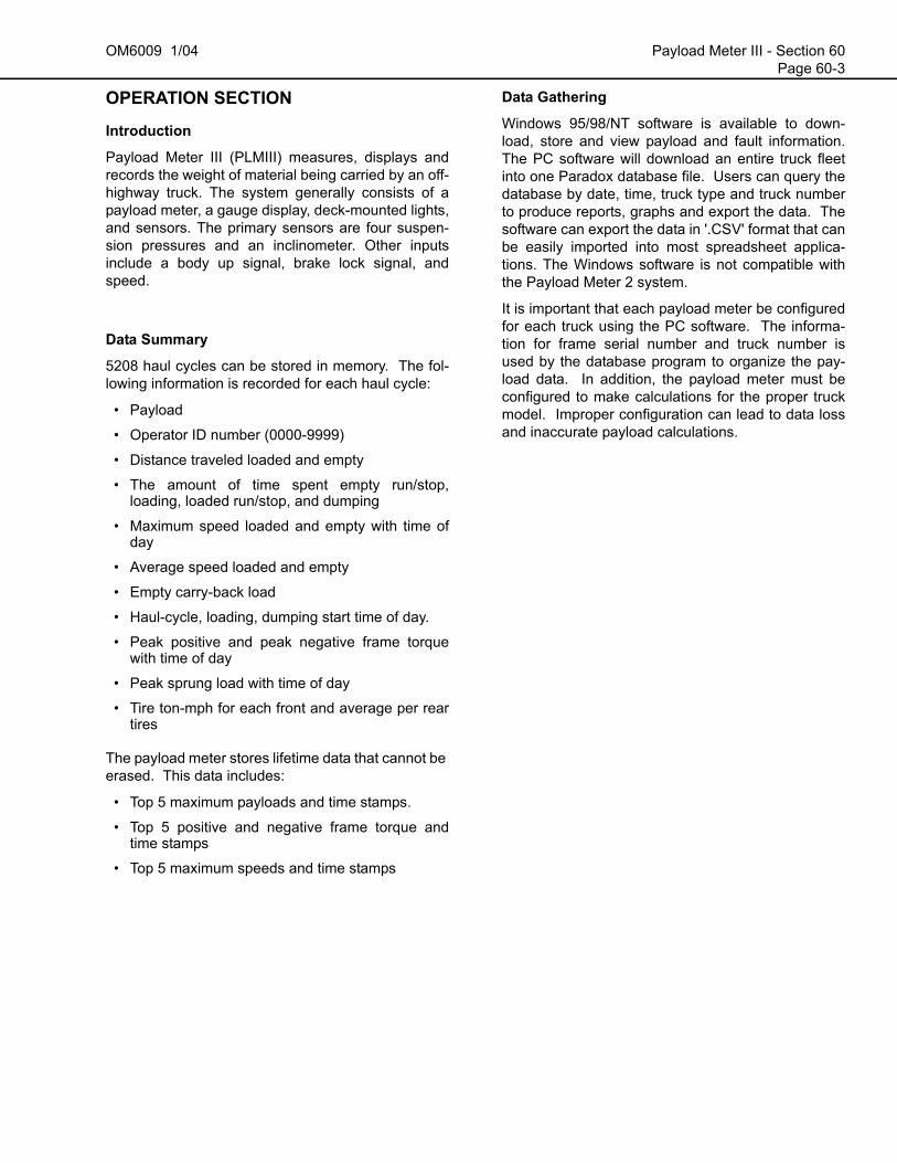
OM6009 1/04 Payload Meter III - Section 60Page 60-3
OPERATION SECTION
Introduction
Payload Meter III (PLMIII) measures, displays andrecords the weight of material being carried by an off-highway truck. The system generally consists of apayload meter, a gauge display, deck-mounted lights,and sensors. The primary sensors are four suspen-sion pressures and an inclinometer. Other inputsinclude a body up signal, brake lock signal, andspeed.
Data Summary
5208 haul cycles can be stored in memory. The fol-lowing information is recorded for each haul cycle:
• Payload
• Operator ID number (0000-9999)
• Distance traveled loaded and empty
• The amount of time spent empty run/stop,loading, loaded run/stop, and dumping
• Maximum speed loaded and empty with time ofday
• Average speed loaded and empty
• Empty carry-back load
• Haul-cycle, loading, dumping start time of day.
• Peak positive and peak negative frame torquewith time of day
• Peak sprung load with time of day
• Tire ton-mph for each front and average per reartires
The payload meter stores lifetime data that cannot be erased. This data includes:
• Top 5 maximum payloads and time stamps.
• Top 5 positive and negative frame torque andtime stamps
• Top 5 maximum speeds and time stamps
Data Gathering
Windows 95/98/NT software is available to down-load, store and view payload and fault information.The PC software will download an entire truck fleetinto one Paradox database file. Users can query thedatabase by date, time, truck type and truck numberto produce reports, graphs and export the data. Thesoftware can export the data in '.CSV' format that canbe easily imported into most spreadsheet applica-tions. The Windows software is not compatible withthe Payload Meter 2 system.
It is important that each payload meter be configuredfor each truck using the PC software. The informa-tion for frame serial number and truck number isused by the database program to organize the pay-load data. In addition, the payload meter must beconfigured to make calculations for the proper truckmodel. Improper configuration can lead to data lossand inaccurate payload calculations.
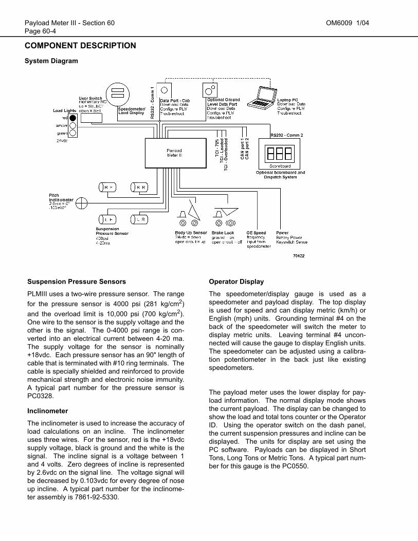
Payload Meter III - Section 60 OM6009 1/04Page 60-4
COMPONENT DESCRIPTION
System Diagram
Suspension Pressure Sensors
PLMIII uses a two-wire pressure sensor. The rangefor the pressure sensor is 4000 psi (281 kg/cm2)and the overload limit is 10,000 psi (700 kg/cm2).One wire to the sensor is the supply voltage and theother is the signal. The 0-4000 psi range is con-verted into an electrical current between 4-20 ma.The supply voltage for the sensor is nominally+18vdc. Each pressure sensor has an 90" length ofcable that is terminated with #10 ring terminals. Thecable is specially shielded and reinforced to providemechanical strength and electronic noise immunity.A typical part number for the pressure sensor isPC0328.
Inclinometer
The inclinometer is used to increase the accuracy ofload calculations on an incline. The inclinometeruses three wires. For the sensor, red is the +18vdcsupply voltage, black is ground and the white is thesignal. The incline signal is a voltage between 1and 4 volts. Zero degrees of incline is representedby 2.6vdc on the signal line. The voltage signal willbe decreased by 0.103vdc for every degree of noseup incline. A typical part number for the inclinome-ter assembly is 7861-92-5330.
Operator Display
The speedometer/display gauge is used as aspeedometer and payload display. The top displayis used for speed and can display metric (km/h) orEnglish (mph) units. Grounding terminal #4 on theback of the speedometer will switch the meter todisplay metric units. Leaving terminal #4 uncon-nected will cause the gauge to display English units.The speedometer can be adjusted using a calibra-tion potentiometer in the back just like existingspeedometers.
The payload meter uses the lower display for pay-load information. The normal display mode showsthe current payload. The display can be changed toshow the load and total tons counter or the OperatorID. Using the operator switch on the dash panel,the current suspension pressures and incline can bedisplayed. The units for display are set using thePC software. Payloads can be displayed in ShortTons, Long Tons or Metric Tons. A typical part num-ber for this gauge is the PC0550.
OM6009 1/04 Payload Meter III - Section 60Page 60-5
Operator Switch
The payload operator switch is used to set, view andclear the Total Load Counter and Total Ton Counter.It is also used to enter the Operator ID number (0-9999). This switch can also be used to view the sus-pension pressures and inclinometer. The payloadmeter operator switch is located on the dashboard. Itis a two-way momentary switch. The top position isthe SELECT position. The SELECT position is usedstep through the different displays. The lower posi-tion is the SET position. The SET position is used toset the Operator ID or clear the load and total toncounters. Normally the inputs from the switch to thepayload meter are open circuit. The switch momen-tarily connects the circuit to ground.
Speed Input
PLMIII uses a speed signal to calculate speed, dis-tance, and other performance data. This input is crit-ical to the proper operation of the system. PLMIIIreceives this signal from the speedometer/operatordisplay on the dashboard. The same signal dis-played to the operator is used by the system. Dis-tance calculations are made based on the rollingradius of the tires for a particular truck.
Body-Up Switch
The Body-Up input signal is received from a mag-netic switch located on the inside of the truck frame,forward the pivot pin of the truck body. This is thesame switch typically used for input to the drive sys-tem. When the body is down, the switch closes andcompletes the circuit to 71-Control Power. 24vdcindicates the body is down. Open circuit indicatesthat the body is up.
Brake Lock Switch
The brake lock is used to lock the rear brakes on thetruck. It is necessary for the accurate calculation ofswingloads during the loading process. Without thebrake lock applied, the payload meter will not calcu-late swingloads during the loading process. Withoutthe brake lock, the payload meter will assume thatthe truck was loaded using a continuous loader andflag the haul cycle record. All other functions will benormal regardless of brake lock usage. The brakelock input comes from the switch located on the dashpanel. The brake lock switch connects the circuit toground. Open circuit indicates brake lock off.Ground indicates brake lock on.
Payload Meter
The payload meter is housed in a black aluminumhousing. There is a small window on the face of theunit. Status and active alarm codes can be viewedthrough the window. During normal operation, a two-digit display flashes 0 back and forth. Active faultcodes will be displayed for two seconds. Thesecodes are typically viewed using the laptop computerconnected to the serial communications port.
There is one 40-pin connector on the payload meter.A jack-screw is used to hold the payload meter andwire harness connector housings together. Thisscrew requires a 4mm or 5/32 hex wrench. The cor-rect tightening torque for this screw is 25 lb-in. Fourbolts hold the payload meter housing to its mountingbracket in the cab.
The circuit board inside the payload meter housing ismade from multi-layer, dual-sided surface-mountelectronics. There are no field serviceable compo-nents inside. The electronics are designed to with-stand the harsh operating environment of the miningindustry. Opening the payload meter housing willresult in voiding the warranty.
Communications Ports
The payload meter has two RS232 serial communi-cations ports and two CAN ports. Connections forthe two serial ports are available inside the payloadmeter junction box. The two CAN ports are availablefor future electronics systems.
Serial port #1 is used to communicate with the dash-board display. It is also used to connect to the laptopcomputer. The display gauge will remain blank whenthe PC is using the serial port. This port initially oper-ates with serial settings at 9600,8,N,1. These set-tings change automatically to increase thecommunications rate when the PC is using the port.This serial port uses a 3-wire hardware connection.
Serial port #2 is used to communicate to other on-board electronics like Modular Mining's Dispatch®system or the Scoreboard from Komatsu. This portuses a 3-wire hardware connection. Connections tothis serial port need to be approved by Komatsu.Several protocol options are available and detailedtechnical information is available depending onlicensing.
Payload Meter III - Section 60 OM6009 1/04Page 60-6
Keyswitch Input
PLMIII monitors the status of the keyswitch. 24vdcindicates that the keyswitch is on, open indicates thekeyswitch is OFF. The payload meter does notreceive its electrical power from the keyswitch circuit.The payload meter will remain on for several sec-onds after keyswitch is removed. When the key-switch power is removed, payload meter performs aseries of internal memory operations before turningitself off. To allow for these operations, the key-switch should be turned OFF for at least 15 secondsbefore turning the keyswitch back on. The payloadmeter will automatically reset itself without error if notenough time is given for these operations. The dis-play may blink briefly.
Payload Meter Power
The payload meter receives its power from the bat-tery circuit on the truck. Removing battery powerfrom the payload meter before removing keyswitchand waiting 15 seconds may result in lost haul cycledata. The payload meter turns itself off approximately15 seconds after the keyswitch power is removed.Some haul cycle data will be lost if battery power isremoved before waiting 15 seconds. The payloadmeter system operates at a nominal voltage of 24vdcat 1 to 2 amps depending on options. The payloadmeter is designed to turn itself off if the supply volt-age rises above 36vdc. The payload meter is alsoprotected by a 5 amp circuit breaker located in thejunction box.
Power to the load lights comes from the same batterycircuit. The load lights are powered through a relay.The keyswitch circuit controls the relay. The loadlights are also protected by a 15 amp circuit breakerin the junction box.
Load Lights
PLMIII uses load lights to indicate to the shovel oper-ator the approximate weight of the material in thetruck. The load lights are illuminated only when thebrake lock is applied. The lights are controlled by thepayload meter through a series of relays in the junc-tion box. The payload meter controls the relays with24vdc outputs. A 24vdc signal from the payloadmeter powers the relay coil and connects batterypower to the load light. When the relay is not pow-ered by the payload meter, a pre-warm resistor con-nects the load light to a reduced voltage. This circuitpre-warms the load light filaments and reduces theinrush current when the light is fully illuminated. Thislengthens the operating life of the load lights.
The load lights progressively indicate to the shoveloperator the approximate weight of the material inthe truck.
A flashing green light indicates the next swingloadwill make the measured load greater than 50% ofrated load. A solid green light indicates that the cur-rent load is greater than 50% of rated capacity.
A flashing amber light indicates the next swingloadwill make the measured load greater than 90% ofrated load. A solid amber light indicates that the cur-rent load is greater than 90% of rated capacity.
A flashing red light indicates the next swingload willmake the measured load greater than 105% of ratedload. A solid red light indicates that the current loadis greater than 105% of rated capacity.
The optimal loading target is a solid green and amberlights with a flashing red light. This indicates that theload is between 90% and 105% of rated load for thetruck and the next swingload will load the truck over105%.
OM6009 1/04 Payload Meter III - Section 60Page 60-7
Wiring and Termination
Most of the PLMIII truck connections use a heavy-duty cable. This yellow multi-conductor cable uses a16awg, finely stranded wire designed for continuousmotion operations. The conductors are protected bya foil and braided shield for electronic noise immunityand physical strength. A typical part number for thiswire is LW086-63. This wire is typically terminatedwith a #10 ring terminal, part number VH2584. Mostconnections for the PLMIII system are made in thepayload meter junction box.
TCI Outputs
The GE drive system on the 930E requires informa-tion from the payload meter regarding the loadedcondition of the truck. There are three outputs fromthe payload meter to GE to indicate the relative loadin the truck. 24 vdc on the 73MSL circuit indicatesthat the load is 70% of rated load. 24 vdc on the73FSL circuit indicates the truck is 100% loaded.The 73OSL circuit is not currently used.
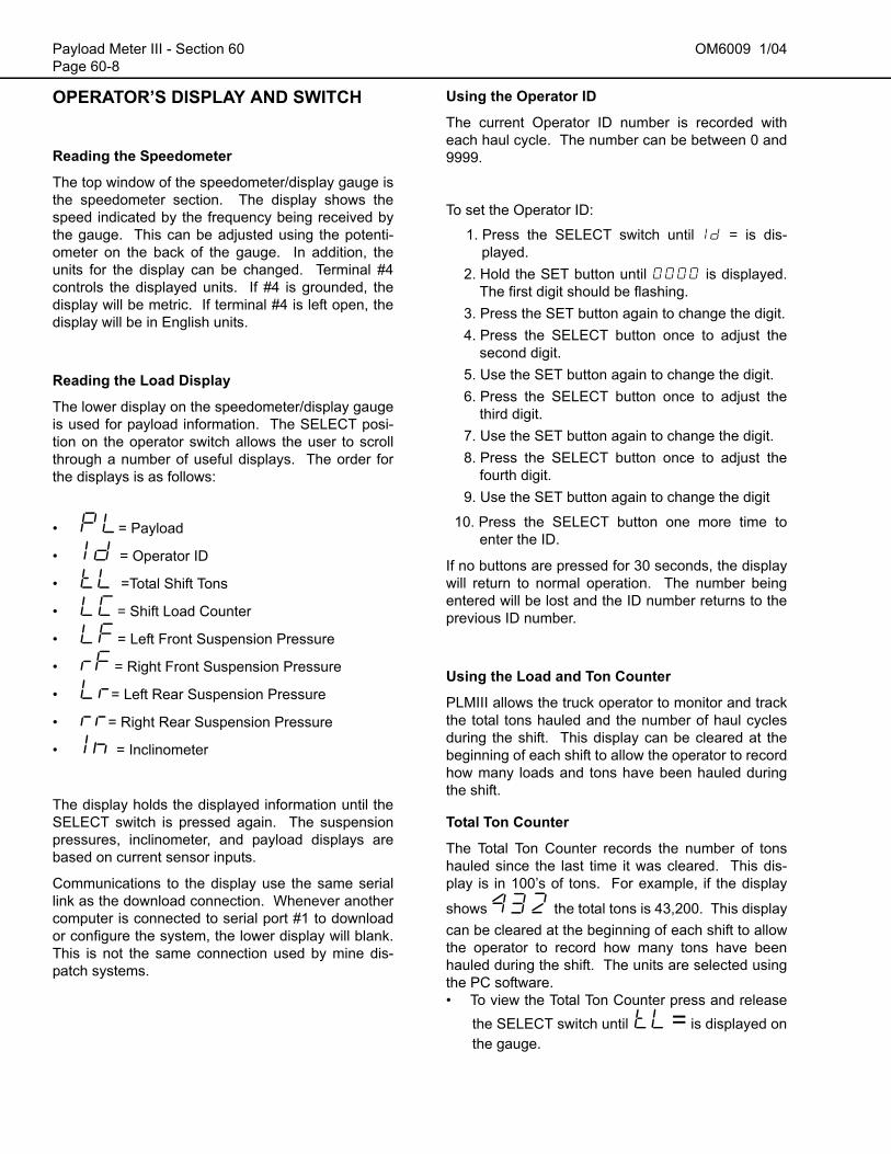
Payload Meter III - Section 60 OM6009 1/04Page 60-8
OPERATOR’S DISPLAY AND SWITCH
Reading the Speedometer
The top window of the speedometer/display gauge isthe speedometer section. The display shows thespeed indicated by the frequency being received bythe gauge. This can be adjusted using the potenti-ometer on the back of the gauge. In addition, theunits for the display can be changed. Terminal #4controls the displayed units. If #4 is grounded, thedisplay will be metric. If terminal #4 is left open, thedisplay will be in English units.
Reading the Load Display
The lower display on the speedometer/display gaugeis used for payload information. The SELECT posi-tion on the operator switch allows the user to scrollthrough a number of useful displays. The order forthe displays is as follows:
• PL= Payload
• Id = Operator ID
• tL =Total Shift Tons
• LC= Shift Load Counter
• LF= Left Front Suspension Pressure
• rF= Right Front Suspension Pressure
• Lr= Left Rear Suspension Pressure
• rr= Right Rear Suspension Pressure
• In = Inclinometer
The display holds the displayed information until theSELECT switch is pressed again. The suspensionpressures, inclinometer, and payload displays arebased on current sensor inputs.
Communications to the display use the same seriallink as the download connection. Whenever anothercomputer is connected to serial port #1 to downloador configure the system, the lower display will blank.This is not the same connection used by mine dis-patch systems.
Using the Operator ID
The current Operator ID number is recorded witheach haul cycle. The number can be between 0 and9999.
To set the Operator ID:
1. Press the SELECT switch until Id = is dis-played.
2. Hold the SET button until 0000 is displayed.The first digit should be flashing.
3. Press the SET button again to change the digit.4. Press the SELECT button once to adjust the
second digit. 5. Use the SET button again to change the digit.6. Press the SELECT button once to adjust the
third digit. 7. Use the SET button again to change the digit.8. Press the SELECT button once to adjust the
fourth digit. 9. Use the SET button again to change the digit
10. Press the SELECT button one more time toenter the ID.
If no buttons are pressed for 30 seconds, the displaywill return to normal operation. The number beingentered will be lost and the ID number returns to theprevious ID number.
Using the Load and Ton Counter
PLMIII allows the truck operator to monitor and trackthe total tons hauled and the number of haul cyclesduring the shift. This display can be cleared at thebeginning of each shift to allow the operator to recordhow many loads and tons have been hauled duringthe shift.
Total Ton Counter
The Total Ton Counter records the number of tonshauled since the last time it was cleared. This dis-play is in 100’s of tons. For example, if the display
shows 432 the total tons is 43,200. This displaycan be cleared at the beginning of each shift to allowthe operator to record how many tons have beenhauled during the shift. The units are selected usingthe PC software.• To view the Total Ton Counter press and release
the SELECT switch until tL = is displayed onthe gauge.
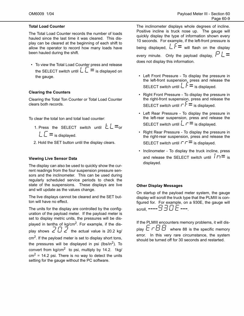
OM6009 1/04 Payload Meter III - Section 60Page 60-9
Total Load Counter
The Total Load Counter records the number of loadshauled since the last time it was cleared. This dis-play can be cleared at the beginning of each shift toallow the operator to record how many loads havebeen hauled during the shift.
• To view the Total Load Counter press and releasethe SELECT switch until LC= is displayed onthe gauge.
Clearing the Counters
Clearing the Total Ton Counter or Total Load Counterclears both records.
To clear the total ton and total load counter:
1. Press the SELECT switch until tL=or
LC= is displayed.
2. Hold the SET button until the display clears.
Viewing Live Sensor Data
The display can also be used to quickly show the cur-rent readings from the four suspension pressure sen-sors and the inclinometer. This can be used duringregularly scheduled service periods to check thestate of the suspensions. These displays are liveand will update as the values change.
The live displays cannot be cleared and the SET but-ton will have no effect.
The units for the display are controlled by the config-uration of the payload meter. If the payload meter isset to display metric units, the pressures will be dis-played in tenths of kg/cm2. For example, if the dis-
play shows 202 the actual value is 20.2 kg/
cm2. If the payload meter is set to display short tons,the pressures will be displayed in psi (lbs/in2). Toconvert from kg/cm2 to psi, multiply by 14.2. 1kg/cm2 = 14.2 psi. There is no way to detect the unitssetting for the gauge without the PC software.
The inclinometer displays whole degrees of incline.Positive incline is truck nose up. The gauge willquickly display the type of information shown every10 seconds. For example, if the left-front pressure is
being displayed, Lf= will flash on the display
every minute. Only the payload display, PL=does not display this information.
• Left Front Pressure - To display the pressure inthe left-front suspension, press and release theSELECT switch until Lf= is displayed.
• Right Front Pressure - To display the pressure inthe right-front suspension, press and release theSELECT switch until rf= is displayed.
• Left Rear Pressure - To display the pressure inthe left-rear suspension, press and release theSELECT switch until Lr= is displayed.
• Right Rear Pressure - To display the pressure inthe right-rear suspension, press and release theSELECT switch until rr= is displayed.
• Inclinometer - To display the truck incline, pressand release the SELECT switch until In= isdisplayed.
Other Display Messages
On startup of the payload meter system, the gaugedisplay will scroll the truck type that the PLMIII is con-figured for. For example, on a 930E, the gauge will
scroll, ----930E---.
If the PLMIII encounters memory problems, it will dis-
play Er88 where 88 is the specific memoryerror. In this very rare circumstance, the systemshould be turned off for 30 seconds and restarted.
Payload Meter III - Section 60 OM6009 1/04Page 60-10
PAYLOAD OPERATION & CALCULATION
Description of Haul Cycle States
The typical haul cycle can be broken down into eightdistinct stages or states. Each state requires the pay-load meter to make different calculations and storedifferent data.
States or stages of a typical haul cycle
1. Tare Zone2. Empty3. Loading4. Maneuvering5. Final Zone6. Hauling7. Dumping8. After Dump
Haul Cycle Description
A new haul cycle is started after the load has beendumped from the previous cycle. The payload meterwill stay in the after_dump state for 10 seconds toconfirm that the load has actually been dumped. Ifthe current payload is less than 20% of rated load,the payload meter will switch to the tare_zone andbegin calculating a new empty tare. If, after dump-ing, the payload has not dropped below 20% of ratedload the meter will return to the maneuvering or haul-ing states. In this case, the false_body_up flag willbe recorded in the haul cycle record.
While in the tare_zone state, and moving faster than5 km/h (3 mph), the payload meter calculates theempty sprung weight of the truck. This tare value willbe subtracted from the loaded sprung weight to cal-culate the final payload. The payload meter willswitch from the tare_zone or empty to the loadingstate if swingloads are detected. By raising thedump body while in the empty state the payloadmeter can be manually switched back to thetare_zone to calculate a new tare.
From the empty state, the payload meter will switchto the loading state through one of two means. If thebrake lock is applied, the payload meter will be ana-lyzing the suspension pressures to detect a swing-load. If a swingload is detected, the meter will switchto the loading state. The minimum size for swingloaddetection is 10% of rated load. Swingload detectionusually takes 4-6 seconds. The second method toswitch from empty to loading is through continuousloading. This can happen if the brake lock is notused during loading. If the load increases above50% of rated load for 10 seconds without the brake
lock applied, the meter will switch to loading andrecord the continuous_loading flag in the haul cycle.
The payload meter switches from loading to maneu-vering as soon as the truck begins moving. Themaneuvering zone is 160m and is designed to allowthe operator to reposition the truck under the shovel.More payload can be added anytime within themaneuvering zone. Once the truck travels 160m (0.1miles) the payload meter switches to the final_zoneand begins calculating payload. If the body is raisedwhile the payload meter is in the maneuvering state,the no_final_load flag will be recorded in the haulcycle record, no payload will be calculated, and themeter will switch to the dumping state.
While in the final_zone moving faster than 5 km/h (3mph), the payload meter calculates the loadedsprung weight of the truck. The same advancedalgorithm is used to calculate the empty and loadedsprung weights. The payload meter will switch fromthe final_zone to the dumping state if the Body-Upsignal is received. If the truck has moved for lessthan 1 minute in the final_zone, the payload meterwill calculate the final payload using an averagingtechnique which may be less accurate. If this hap-pens, the average_load flag will be recorded in thehaul cycle.
The payload meter switches to the dumping statewhen the dump body rises. The payload meter willswitch from dumping to after_dump when the dumpbody comes back down.
From the after_dump, the payload meter will switchto one of three states:
1. If the average payload is greater than 20% ofrated load and no final payload has been calcu-lated, the payload meter will return to themaneuvering state. After the truck travels160m (0.1 mile) the meter will switch to thefinal_zone and attempt to calculate the payloadagain. The false_body_up flag will be recordedin the haul cycle record.
2. If the average payload is greater than 20% ofrated load and the final payload has been calcu-lated, the payload meter will switch back to thehauling state. The false_body_up flag will berecorded in the haul cycle record.
3. If the average payload is less than 20% of ratedload, the payload meter will switch to thetare_zone and begin to calculate a new emptytare.
OM6009 1/04 Payload Meter III - Section 60Page 60-11
Load Calculation
The final load calculation is different from the lastswingload calculation. The accuracy of the swingload calculation depends on loading conditions andthe position of the truck during loading. The lastswingload calculation is not the value recorded inmemory as the final load. The final load is deter-mined by a series of calculations made while thetruck is traveling to the dump site.
Carry Back
Carry back is calculated as the difference betweenthe current truck tare and the clean truck tare. Theclean truck tare is calculated using the PC software.When the suspensions are serviced or changes aremade that may affect the sprung weight of the truck,a new clean truck tare should be calculated.
Measurement Accuracy
Payload measurements are typically repeatablewithin 1%. Accuracy for a particular scale testdepends on specific combinations of pressure sen-sors and payload meters as well as the specifics ofeach scale test. Comparisons from different scaletests are often made without considering the differ-ences introduced by the specific installation andoperation of the scales for each test. In addition,each pressure sensor and payload meter introducesit's own non-linearity. Each truck becomes an indi-vidual combination of sensors and payload meter.Errors from these sources can introduce up to a ±7%bias in the payload meter calculations for a specificscale test, for an individual truck.
Because the PLMIII calculates a new empty tare foreach payload, a detailed scale test must weigh thetrucks empty and loaded for each haul cycle. Usinga simple average of 2 or 3 empty truck weights as anempty tare for the entire scale test will introduce sig-nificant error when comparing scale weights toPLMIII weights.
SOURCES FOR PAYLOAD ERROR
Payload Error
The number one source of error in payload calcula-tion is improperly serviced suspensions. The pay-load meter calculates payload by measuringdifferences in the sprung weight of the truck when itis empty and when it is loaded. The sprung weight isthe weight of the truck supported by the suspensions.The only method for determining sprung weight is bymeasuring the pressure of the nitrogen gas in thesuspensions. If the suspensions are not properlymaintained, the payload meter cannot determine anaccurate value for payload. The two critical factorsare proper oil height and proper nitrogen charge.
If the suspensions are overcharged, the payloadmeter will not be able to determine the empty sprungweight of the truck. The suspension cylinder must beable to travel up and down as the truck drives empty.The pressure in an overcharged suspension canpush the suspension rod to full extension. In thiscase, the pressure inside the cylinder does not accu-rately represent the force necessary to support thatportion of the truck.
If the suspensions are undercharged, the payloadmeter will not be able to determine the loaded sprungweight of the truck. The suspension cylinder must beable to travel up and down as the truck drives loaded.If the pressure in an undercharged suspension can-not support the load, the suspension will collapseand make metal-to-metal contact. In this case, thepressure inside the cylinder does not accurately rep-resent the force necessary to support that portion ofthe truck.
Low oil height can also introduce errors by not cor-rectly supporting a loaded truck. This is why the cor-rect oil height and nitrogen charge are the mostcritical factors in the measurement of payload. If thesuspensions are not properly maintained, accuratepayload measurement is not possible. In addition,suspension maintenance is very important to the lifeof the truck.
Payload Meter III - Section 60 OM6009 1/04Page 60-12
Loading Conditions
The final load calculation of the PLMIII system is notsensitive to loading conditions. The final load is cal-culated as the truck travels away from the shovel.Variations in road conditions and slope are compen-sated for in the complex calculations performed bythe payload meter.
Pressure Sensors
Small variations in sensors can also contribute topayload calculation error. Every pressure sensor isslightly different. The accuracy differences of individ-ual sensors along the range from 0 to 4000 psi canadd or subtract from payload measurements. This isalso true of the sensor input circuitry within individualpayload meters. These differences can stack up 7%in extreme cases. These errors will be consistentand repeatable for specific combinations of payloadmeters and sensors on a particular truck.
Swingloads
Swingload calculations can be affected by conditionsat the loading site. Parking the truck against theberm or large debris can cause the payload meter toinaccurately calculate individual swingloads. Whilethe PLMIII system uses an advanced calculationalgorithms to determine swingloads, loading site con-ditions can affect the accuracy.
Speed and Distance
The payload meter receives the same speed signalas the speedometer. This signal is a frequency thatrepresents the speed of the truck. The payloadmeter uses this frequency to calculate speeds anddistances. The meter assumes a single value for therolling radius of the tire. The rolling radius maychange at difference speeds by growing larger athigher speeds. The actual rolling radius of the tirewill also change between a loaded and empty truck.The payload meter does not compensate for thesechanges.
HAUL CYCLE DATAPLMIII records and stores data in its on-board flashmemory. This memory does not require a separatebattery. The data is available through the downloadsoftware.
PLMIII can store 5208 payload records. When thememory is full, the payload meter will erase the old-est 745 payload records and continue recording.
PLMIII can store 512 alarm records in memory.When the memory is full, the payload meter willerase the oldest 312 alarm records and continuerecording.
All data is calculated and stored in metric units withinthe payload meter. The data is downloaded andstored in metric units within the Paradox database onthe PC. The analysis program converts units for dis-plays, graphs and reports.
The units noted in Table 1 are the actual units storedin the data file. The value for the haul cycle start timeis the number of seconds since January 1, 1970 tothe start of the haul cycle. All other event times arereferenced in seconds since the haul cycle start time.The PC download and analysis program convertsthese numbers into dates and times for graphs andreports.
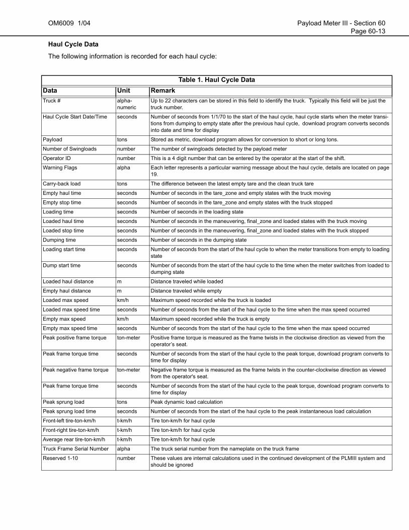
OM6009 1/04 Payload Meter III - Section 60Page 60-13
Haul Cycle Data
The following information is recorded for each haul cycle:
Table 1. Haul Cycle DataData Unit RemarkTruck # alpha-
numericUp to 22 characters can be stored in this field to identify the truck. Typically this field will be just the truck number.
Haul Cycle Start Date/Time seconds Number of seconds from 1/1/70 to the start of the haul cycle, haul cycle starts when the meter transi-tions from dumping to empty state after the previous haul cycle, download program converts seconds into date and time for display
Payload tons Stored as metric, download program allows for conversion to short or long tons.
Number of Swingloads number The number of swingloads detected by the payload meter
Operator ID number This is a 4 digit number that can be entered by the operator at the start of the shift.
Warning Flags alpha Each letter represents a particular warning message about the haul cycle, details are located on page 19.
Carry-back load tons The difference between the latest empty tare and the clean truck tare
Empty haul time seconds Number of seconds in the tare_zone and empty states with the truck moving
Empty stop time seconds Number of seconds in the tare_zone and empty states with the truck stopped
Loading time seconds Number of seconds in the loading state
Loaded haul time seconds Number of seconds in the maneuvering, final_zone and loaded states with the truck moving
Loaded stop time seconds Number of seconds in the maneuvering, final_zone and loaded states with the truck stopped
Dumping time seconds Number of seconds in the dumping state
Loading start time seconds Number of seconds from the start of the haul cycle to when the meter transitions from empty to loading state
Dump start time seconds Number of seconds from the start of the haul cycle to the time when the meter switches from loaded to dumping state
Loaded haul distance m Distance traveled while loaded
Empty haul distance m Distance traveled while empty
Loaded max speed km/h Maximum speed recorded while the truck is loaded
Loaded max speed time seconds Number of seconds from the start of the haul cycle to the time when the max speed occurred
Empty max speed km/h Maximum speed recorded while the truck is empty
Empty max speed time seconds Number of seconds from the start of the haul cycle to the time when the max speed occurred
Peak positive frame torque ton-meter Positive frame torque is measured as the frame twists in the clockwise direction as viewed from the operator’s seat.
Peak frame torque time seconds Number of seconds from the start of the haul cycle to the peak torque, download program converts to time for display
Peak negative frame torque ton-meter Negative frame torque is measured as the frame twists in the counter-clockwise direction as viewed from the operator's seat.
Peak frame torque time seconds Number of seconds from the start of the haul cycle to the peak torque, download program converts to time for display
Peak sprung load tons Peak dynamic load calculation
Peak sprung load time seconds Number of seconds from the start of the haul cycle to the peak instantaneous load calculation
Front-left tire-ton-km/h t-km/h Tire ton-km/h for haul cycle
Front-right tire-ton-km/h t-km/h Tire ton-km/h for haul cycle
Average rear tire-ton-km/h t-km/h Tire ton-km/h for haul cycle
Truck Frame Serial Number alpha The truck serial number from the nameplate on the truck frame
Reserved 1-10 number These values are internal calculations used in the continued development of the PLMIII system and should be ignored
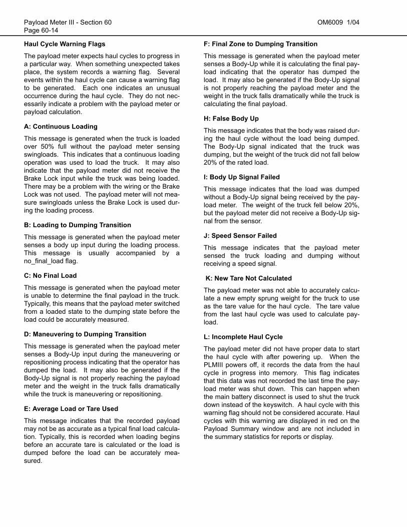
Payload Meter III - Section 60 OM6009 1/04Page 60-14
Haul Cycle Warning Flags
The payload meter expects haul cycles to progress ina particular way. When something unexpected takesplace, the system records a warning flag. Severalevents within the haul cycle can cause a warning flagto be generated. Each one indicates an unusualoccurrence during the haul cycle. They do not nec-essarily indicate a problem with the payload meter orpayload calculation.
A: Continuous Loading
This message is generated when the truck is loadedover 50% full without the payload meter sensingswingloads. This indicates that a continuous loadingoperation was used to load the truck. It may alsoindicate that the payload meter did not receive theBrake Lock input while the truck was being loaded.There may be a problem with the wiring or the BrakeLock was not used. The payload meter will not mea-sure swingloads unless the Brake Lock is used dur-ing the loading process.
B: Loading to Dumping Transition
This message is generated when the payload metersenses a body up input during the loading process.This message is usually accompanied by ano_final_load flag.
C: No Final Load
This message is generated when the payload meteris unable to determine the final payload in the truck.Typically, this means that the payload meter switchedfrom a loaded state to the dumping state before theload could be accurately measured.
D: Maneuvering to Dumping Transition
This message is generated when the payload metersenses a Body-Up input during the maneuvering orrepositioning process indicating that the operator hasdumped the load. It may also be generated if theBody-Up signal is not properly reaching the payloadmeter and the weight in the truck falls dramaticallywhile the truck is maneuvering or repositioning.
E: Average Load or Tare Used
This message indicates that the recorded payloadmay not be as accurate as a typical final load calcula-tion. Typically, this is recorded when loading beginsbefore an accurate tare is calculated or the load isdumped before the load can be accurately mea-sured.
F: Final Zone to Dumping Transition
This message is generated when the payload metersenses a Body-Up while it is calculating the final pay-load indicating that the operator has dumped theload. It may also be generated if the Body-Up signalis not properly reaching the payload meter and theweight in the truck falls dramatically while the truck iscalculating the final payload.
H: False Body Up
This message indicates that the body was raised dur-ing the haul cycle without the load being dumped.The Body-Up signal indicated that the truck wasdumping, but the weight of the truck did not fall below20% of the rated load.
I: Body Up Signal Failed
This message indicates that the load was dumpedwithout a Body-Up signal being received by the pay-load meter. The weight of the truck fell below 20%,but the payload meter did not receive a Body-Up sig-nal from the sensor.
J: Speed Sensor Failed
This message indicates that the payload metersensed the truck loading and dumping withoutreceiving a speed signal.
K: New Tare Not Calculated
The payload meter was not able to accurately calcu-late a new empty sprung weight for the truck to useas the tare value for the haul cycle. The tare valuefrom the last haul cycle was used to calculate pay-load.
L: Incomplete Haul Cycle
The payload meter did not have proper data to startthe haul cycle with after powering up. When thePLMIII powers off, it records the data from the haulcycle in progress into memory. This flag indicatesthat this data was not recorded the last time the pay-load meter was shut down. This can happen whenthe main battery disconnect is used to shut the truckdown instead of the keyswitch. A haul cycle with thiswarning flag should not be considered accurate. Haulcycles with this warning are displayed in red on thePayload Summary window and are not included inthe summary statistics for reports or display.
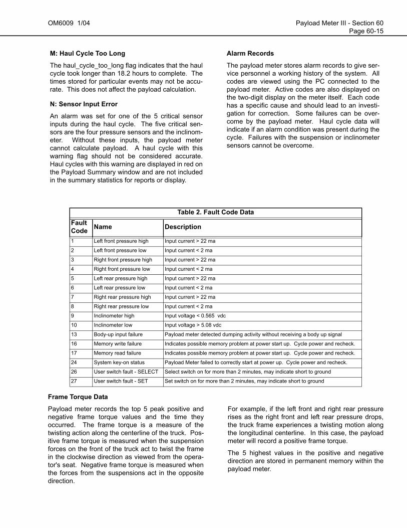
OM6009 1/04 Payload Meter III - Section 60Page 60-15
Frame Torque Data
Payload meter records the top 5 peak positive andnegative frame torque values and the time theyoccurred. The frame torque is a measure of thetwisting action along the centerline of the truck. Pos-itive frame torque is measured when the suspensionforces on the front of the truck act to twist the framein the clockwise direction as viewed from the opera-tor's seat. Negative frame torque is measured whenthe forces from the suspensions act in the oppositedirection.
For example, if the left front and right rear pressurerises as the right front and left rear pressure drops,the truck frame experiences a twisting motion alongthe longitudinal centerline. In this case, the payloadmeter will record a positive frame torque.
The 5 highest values in the positive and negativedirection are stored in permanent memory within thepayload meter.
M: Haul Cycle Too Long
The haul_cycle_too_long flag indicates that the haulcycle took longer than 18.2 hours to complete. Thetimes stored for particular events may not be accu-rate. This does not affect the payload calculation.
N: Sensor Input Error
An alarm was set for one of the 5 critical sensorinputs during the haul cycle. The five critical sen-sors are the four pressure sensors and the inclinom-eter. Without these inputs, the payload metercannot calculate payload. A haul cycle with thiswarning flag should not be considered accurate.Haul cycles with this warning are displayed in red onthe Payload Summary window and are not includedin the summary statistics for reports or display.
Alarm Records
The payload meter stores alarm records to give ser-vice personnel a working history of the system. Allcodes are viewed using the PC connected to thepayload meter. Active codes are also displayed onthe two-digit display on the meter itself. Each codehas a specific cause and should lead to an investi-gation for correction. Some failures can be over-come by the payload meter. Haul cycle data willindicate if an alarm condition was present during thecycle. Failures with the suspension or inclinometersensors cannot be overcome.
Table 2. Fault Code DataFaultCode Name Description
1 Left front pressure high Input current > 22 ma
2 Left front pressure low Input current < 2 ma
3 Right front pressure high Input current > 22 ma
4 Right front pressure low Input current < 2 ma
5 Left rear pressure high Input current > 22 ma
6 Left rear pressure low Input current < 2 ma
7 Right rear pressure high Input current > 22 ma
8 Right rear pressure low Input current < 2 ma
9 Inclinometer high Input voltage < 0.565 vdc
10 Inclinometer low Input voltage > 5.08 vdc
13 Body-up input failure Payload meter detected dumping activity without receiving a body up signal
16 Memory write failure Indicates possible memory problem at power start up. Cycle power and recheck.
17 Memory read failure Indicates possible memory problem at power start up. Cycle power and recheck.
24 System key-on status Payload Meter failed to correctly start at power up. Cycle power and recheck.
26 User switch fault - SELECT Select switch on for more than 2 minutes, may indicate short to ground
27 User switch fault - SET Set switch on for more than 2 minutes, may indicate short to ground
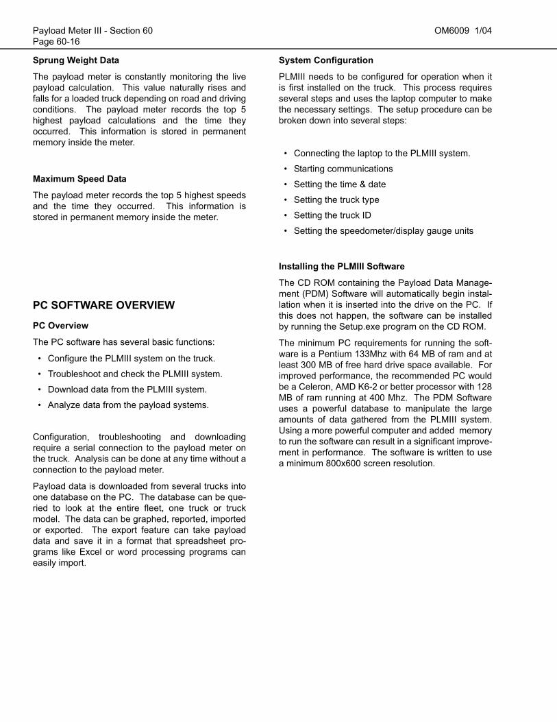
Payload Meter III - Section 60 OM6009 1/04Page 60-16
Sprung Weight Data
The payload meter is constantly monitoring the livepayload calculation. This value naturally rises andfalls for a loaded truck depending on road and drivingconditions. The payload meter records the top 5highest payload calculations and the time theyoccurred. This information is stored in permanentmemory inside the meter.
Maximum Speed Data
The payload meter records the top 5 highest speedsand the time they occurred. This information isstored in permanent memory inside the meter.
PC SOFTWARE OVERVIEW
PC Overview
The PC software has several basic functions:
• Configure the PLMIII system on the truck.
• Troubleshoot and check the PLMIII system.
• Download data from the PLMIII system.
• Analyze data from the payload systems.
Configuration, troubleshooting and downloadingrequire a serial connection to the payload meter onthe truck. Analysis can be done at any time without aconnection to the payload meter.
Payload data is downloaded from several trucks intoone database on the PC. The database can be que-ried to look at the entire fleet, one truck or truckmodel. The data can be graphed, reported, importedor exported. The export feature can take payloaddata and save it in a format that spreadsheet pro-grams like Excel or word processing programs caneasily import.
System Configuration
PLMIII needs to be configured for operation when itis first installed on the truck. This process requiresseveral steps and uses the laptop computer to makethe necessary settings. The setup procedure can bebroken down into several steps:
• Connecting the laptop to the PLMIII system.
• Starting communications
• Setting the time & date
• Setting the truck type
• Setting the truck ID
• Setting the speedometer/display gauge units
Installing the PLMIII Software
The CD ROM containing the Payload Data Manage-ment (PDM) Software will automatically begin instal-lation when it is inserted into the drive on the PC. Ifthis does not happen, the software can be installedby running the Setup.exe program on the CD ROM.
The minimum PC requirements for running the soft-ware is a Pentium 133Mhz with 64 MB of ram and atleast 300 MB of free hard drive space available. Forimproved performance, the recommended PC wouldbe a Celeron, AMD K6-2 or better processor with 128MB of ram running at 400 Mhz. The PDM Softwareuses a powerful database to manipulate the largeamounts of data gathered from the PLMIII system.Using a more powerful computer and added memoryto run the software can result in a significant improve-ment in performance. The software is written to usea minimum 800x600 screen resolution.
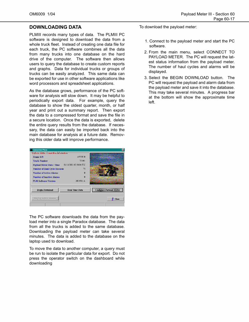
OM6009 1/04 Payload Meter III - Section 60Page 60-17
DOWNLOADING DATAPLMIII records many types of data. The PLMIII PCsoftware is designed to download the data from awhole truck fleet. Instead of creating one data file foreach truck, the PC software combines all the datafrom many trucks into one database on the harddrive of the computer. The software then allowsusers to query the database to create custom reportsand graphs. Data for individual trucks or groups oftrucks can be easily analyzed. This same data canbe exported for use in other software applications likeword processors and spreadsheet applications.
As the database grows, performance of the PC soft-ware for analysis will slow down. It may be helpful toperiodically export data. For example, query thedatabase to show the oldest quarter, month, or halfyear and print out a summary report. Then exportthe data to a compressed format and save the file ina secure location. Once the data is exported, deletethe entire query results from the database. If neces-sary, the data can easily be imported back into themain database for analysis at a future date. Remov-ing this older data will improve performance.
The PC software downloads the data from the pay-load meter into a single Paradox database. The datafrom all the trucks is added to the same database.Downloading the payload meter can take severalminutes. The data is added to the database on thelaptop used to download.
To move the data to another computer, a query mustbe run to isolate the particular data for export. Do notpress the operator switch on the dashboard whiledownloading
To download the payload meter:
1. Connect to the payload meter and start the PCsoftware.
2. From the main menu, select CONNECT TOPAYLOAD METER. The PC will request the lat-est status information from the payload meter.The number of haul cycles and alarms will bedisplayed.
3. Select the BEGIN DOWNLOAD button. ThePC will request the payload and alarm data fromthe payload meter and save it into the database.This may take several minutes. A progress barat the bottom will show the approximate timeleft.
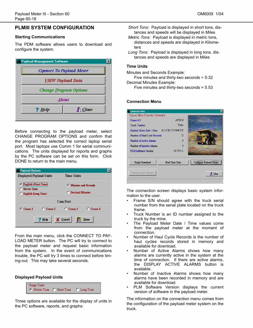
Payload Meter III - Section 60 OM6009 1/04Page 60-18
PLMIII SYSTEM CONFIGURATION
Starting Communications
The PDM software allows users to download andconfigure the system.
Before connecting to the payload meter, selectCHANGE PROGRAM OPTIONS and confirm thatthe program has selected the correct laptop serialport. Most laptops use Comm 1 for serial communi-cations. The units displayed for reports and graphsby the PC software can be set on this form. ClickDONE to return to the main menu.
From the main menu, click the CONNECT TO PAY-LOAD METER button. The PC will try to connect tothe payload meter and request basic informationfrom the system. In the event of communicationstrouble, the PC will try 3 times to connect before tim-ing-out. This may take several seconds.
Displayed Payload Units
Three options are available for the display of units inthe PC software, reports, and graphs:
Short Tons: Payload is displayed in short tons, dis-tances and speeds will be displayed in Miles
Metric Tons: Payload is displayed in metric tons, distances and speeds are displayed in Kilome-ters
Long Tons: Payload is displayed in long tons, dis-tances and speeds are displayed in Miles
Time UnitsMinutes and Seconds Example:
Five minutes and thirty-two seconds = 5:32Decimal Minutes Example:
Five minutes and thirty-two seconds = 5.53
Connection Menu
The connection screen displays basic system infor-mation to the user. • Frame S/N should agree with the truck serial
number from the serial plate located on the truckframe.
• Truck Number is an ID number assigned to thetruck by the mine.
• The Payload Meter Date / Time values comefrom the payload meter at the moment ofconnection.
• Number of Haul Cycle Records is the number ofhaul cycles records stored in memory andavailable for download.
• Number of Active Alarms shows how manyalarms are currently active in the system at thetime of connection. If there are active alarms,the DISPLAY ACTIVE ALARMS button isavailable.
• Number of Inactive Alarms shows how manyalarms have been recorded in memory and areavailable for download.
• PLM Software Version displays the currentversion of software in the payload meter.
The information on the connection menu comes fromthe configuration of the payload meter system on thetruck.
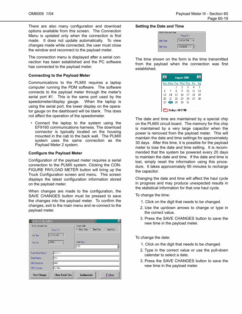
OM6009 1/04 Payload Meter III - Section 60Page 60-19
There are also many configuration and downloadoptions available from this screen. The ConnectionMenu is updated only when the connection is firstmade. It does not update automatically. To viewchanges made while connected, the user must closethe window and reconnect to the payload meter.
The connection menu is displayed after a serial con-nection has been established and the PC softwarehas connected to the payload meter.
Connecting to the Payload Meter
Communications to the PLMIII requires a laptopcomputer running the PDM software. The softwareconnects to the payload meter through the meter'sserial port #1. This is the same port used by thespeedometer/display gauge. When the laptop isusing the serial port, the lower display on the opera-tor gauge on the dashboard will be blank. This doesnot affect the operation of the speedometer.
• Connect the laptop to the system using theEF9160 communications harness. The downloadconnector is typically located on the housingmounted in the cab to the back wall. The PLMIIIsystem uses the same connection as thePayload Meter 2 system.
Configure the Payload Meter
Configuration of the payload meter requires a serialconnection to the PLMIII system. Clicking the CON-FIGURE PAYLOAD METER button will bring up theTruck Configuration screen and menu. This screendisplays the latest configuration information storedon the payload meter.
When changes are made to the configuration, theSAVE CHANGES button must be pressed to savethe changes into the payload meter. To confirm thechanges, exit to the main menu and re-connect to thepayload meter.
Setting the Date and Time
The time shown on the form is the time transmittedfrom the payload when the connection was firstestablished.
The date and time are maintained by a special chipon the PLMIII circuit board. The memory for this chipis maintained by a very large capacitor when thepower is removed from the payload meter. This willmaintain the date and time settings for approximately30 days. After this time, it is possible for the payloadmeter to lose the date and time setting. It is recom-mended that the system be powered every 20 daysto maintain the date and time. If the date and time islost, simply reset the information using this proce-dure. It takes approximately 90 minutes to rechargethe capacitor.
Changing the date and time will affect the haul cyclein progress and may produce unexpected results inthe statistical information for that one haul cycle.
To change the time:
1. Click on the digit that needs to be changed.2. Use the up/down arrows to change or type in
the correct value.3. Press the SAVE CHANGES button to save the
new time in the payload meter.
To change the date:
1. Click on the digit that needs to be changed.2. Type in the correct value or use the pull-down
calendar to select a date.3. Press the SAVE CHANGES button to save the
new time in the payload meter.
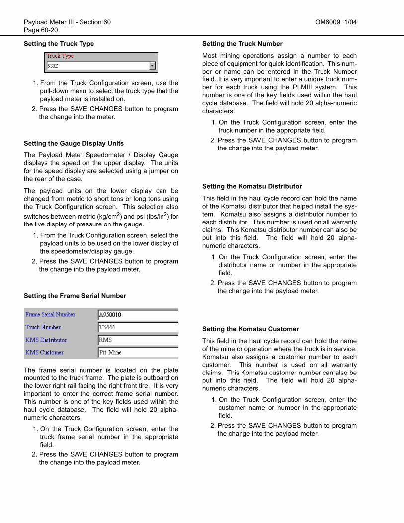
Payload Meter III - Section 60 OM6009 1/04Page 60-20
Setting the Truck Type
1. From the Truck Configuration screen, use thepull-down menu to select the truck type that thepayload meter is installed on.
2. Press the SAVE CHANGES button to programthe change into the meter.
Setting the Gauge Display Units
The Payload Meter Speedometer / Display Gaugedisplays the speed on the upper display. The unitsfor the speed display are selected using a jumper onthe rear of the case.
The payload units on the lower display can bechanged from metric to short tons or long tons usingthe Truck Configuration screen. This selection alsoswitches between metric (kg/cm2) and psi (lbs/in2) forthe live display of pressure on the gauge.
1. From the Truck Configuration screen, select thepayload units to be used on the lower display ofthe speedometer/display gauge.
2. Press the SAVE CHANGES button to programthe change into the payload meter.
Setting the Frame Serial Number
The frame serial number is located on the platemounted to the truck frame. The plate is outboard onthe lower right rail facing the right front tire. It is veryimportant to enter the correct frame serial number.This number is one of the key fields used within thehaul cycle database. The field will hold 20 alpha-numeric characters.
1. On the Truck Configuration screen, enter thetruck frame serial number in the appropriatefield.
2. Press the SAVE CHANGES button to programthe change into the payload meter.
Setting the Truck Number
Most mining operations assign a number to eachpiece of equipment for quick identification. This num-ber or name can be entered in the Truck Numberfield. It is very important to enter a unique truck num-ber for each truck using the PLMIII system. Thisnumber is one of the key fields used within the haulcycle database. The field will hold 20 alpha-numericcharacters.
1. On the Truck Configuration screen, enter thetruck number in the appropriate field.
2. Press the SAVE CHANGES button to programthe change into the payload meter.
Setting the Komatsu Distributor
This field in the haul cycle record can hold the nameof the Komatsu distributor that helped install the sys-tem. Komatsu also assigns a distributor number toeach distributor. This number is used on all warrantyclaims. This Komatsu distributor number can also beput into this field. The field will hold 20 alpha-numeric characters.
1. On the Truck Configuration screen, enter thedistributor name or number in the appropriatefield.
2. Press the SAVE CHANGES button to programthe change into the payload meter.
Setting the Komatsu Customer
This field in the haul cycle record can hold the nameof the mine or operation where the truck is in service.Komatsu also assigns a customer number to eachcustomer. This number is used on all warrantyclaims. This Komatsu customer number can also beput into this field. The field will hold 20 alpha-numeric characters.
1. On the Truck Configuration screen, enter thecustomer name or number in the appropriatefield.
2. Press the SAVE CHANGES button to programthe change into the payload meter.
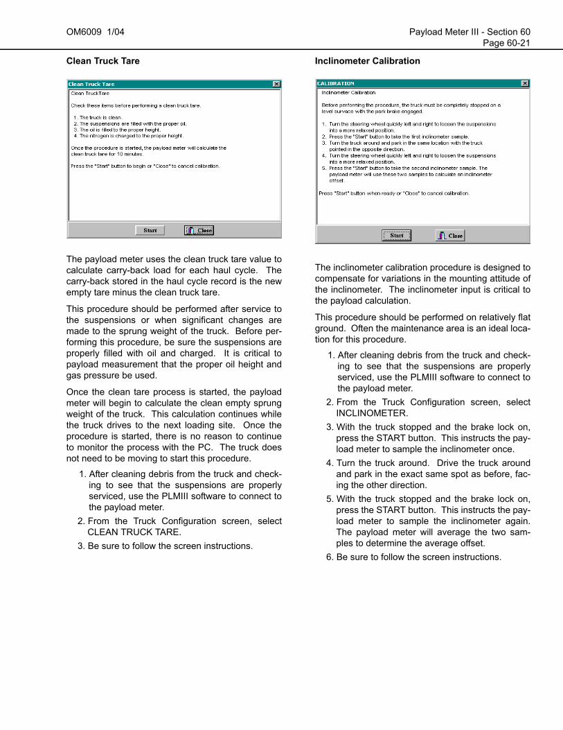
OM6009 1/04 Payload Meter III - Section 60Page 60-21
Clean Truck Tare
The payload meter uses the clean truck tare value tocalculate carry-back load for each haul cycle. Thecarry-back stored in the haul cycle record is the newempty tare minus the clean truck tare.
This procedure should be performed after service tothe suspensions or when significant changes aremade to the sprung weight of the truck. Before per-forming this procedure, be sure the suspensions areproperly filled with oil and charged. It is critical topayload measurement that the proper oil height andgas pressure be used.
Once the clean tare process is started, the payloadmeter will begin to calculate the clean empty sprungweight of the truck. This calculation continues whilethe truck drives to the next loading site. Once theprocedure is started, there is no reason to continueto monitor the process with the PC. The truck doesnot need to be moving to start this procedure.
1. After cleaning debris from the truck and check-ing to see that the suspensions are properlyserviced, use the PLMIII software to connect tothe payload meter.
2. From the Truck Configuration screen, selectCLEAN TRUCK TARE.
3. Be sure to follow the screen instructions.
Inclinometer Calibration
The inclinometer calibration procedure is designed tocompensate for variations in the mounting attitude ofthe inclinometer. The inclinometer input is critical tothe payload calculation.
This procedure should be performed on relatively flatground. Often the maintenance area is an ideal loca-tion for this procedure.
1. After cleaning debris from the truck and check-ing to see that the suspensions are properlyserviced, use the PLMIII software to connect tothe payload meter.
2. From the Truck Configuration screen, selectINCLINOMETER.
3. With the truck stopped and the brake lock on,press the START button. This instructs the pay-load meter to sample the inclinometer once.
4. Turn the truck around. Drive the truck aroundand park in the exact same spot as before, fac-ing the other direction.
5. With the truck stopped and the brake lock on,press the START button. This instructs the pay-load meter to sample the inclinometer again.The payload meter will average the two sam-ples to determine the average offset.
6. Be sure to follow the screen instructions.
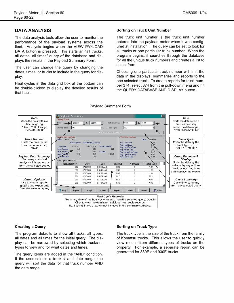
Payload Meter III - Section 60 OM6009 1/04Page 60-22
DATA ANALYSISThe data analysis tools allow the user to monitor theperformance of the payload systems across thefleet. Analysis begins when the VIEW PAYLOADDATA button is pressed. This starts an "all trucks,all dates, all times" query of the database and dis-plays the results in the Payload Summary Form.
The user can change the query by changing thedates, times, or trucks to include in the query for dis-play.
Haul cycles in the data grid box at the bottom canbe double-clicked to display the detailed results ofthat haul.
Sorting on Truck Unit Number
The truck unit number is the truck unit numberentered into the payload meter when it was config-ured at installation. The query can be set to look forall trucks or one particular truck number. When theprogram begins, it searches through the databasefor all the unique truck numbers and creates a list toselect from.
Choosing one particular truck number will limit thedata in the displays, summaries and reports to theone selected truck. To create reports for truck num-ber 374, select 374 from the pull-down menu and hitthe QUERY DATABASE AND DISPLAY button.
Payload Summary Form
Creating a Query
The program defaults to show all trucks, all types,all dates and all times for the initial query. The dis-play can be narrowed by selecting which trucks ortypes to view and for what dates and times.
The query items are added in the "AND" condition.If the user selects a truck # and date range, thequery will sort the data for that truck number ANDthe date range.
Sorting on Truck Type
The truck type is the size of the truck from the familyof Komatsu trucks. This allows the user to quicklyview results from different types of trucks on theproperty. For example, a separate report can begenerated for 830E and 930E trucks.
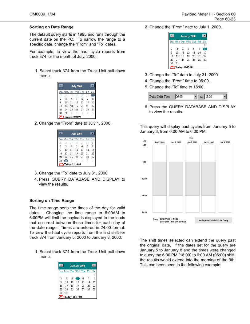
OM6009 1/04 Payload Meter III - Section 60Page 60-23
Sorting on Date Range
The default query starts in 1995 and runs through thecurrent date on the PC. To narrow the range to aspecific date, change the “From” and “To” dates.
For example, to view the haul cycle reports fromtruck 374 for the month of July, 2000:
1. Select truck 374 from the Truck Unit pull-downmenu.
2. Change the “From” date to July 1, 2000.
3. Change the “To” date to July 31, 2000. 4. Press QUERY DATABASE AND DISPLAY to
view the results.
Sorting on Time Range
The time range sorts the times of the day for validdates. Changing the time range to 6:00AM to6:00PM will limit the payloads displayed to the loadsthat occurred between those times for each day ofthe date range. Times are entered in 24:00 format.To view the haul cycle reports from the first shift fortruck 374 from January 5, 2000 to January 8, 2000:
1. Select truck 374 from the Truck Unit pull-downmenu.
2. Change the “From” date to July 1, 2000.
3. Change the “To” date to July 31, 2000. 4. Change the “From” time to 06:00.5. Change the “To” time to 18:00.
6. Press the QUERY DATABASE AND DISPLAYto view the results.
This query will display haul cycles from January 5 toJanuary 8, from 6:00 AM to 6:00 PM.
The shift times selected can extend the query pastthe original date. If the dates set for the query areJanuary 5 to January 8 and the times were changedto query the 6:00 PM (18:00) to 6:00 AM (06:00) shift,the results would extend into the morning of the 9th.This can been seen in the following example:
Date: 1/5/00 to 1/8/00Daily Shift Time: 6:00 to 18:00
0:00
6:00
18:00
24:00
12:00
Jan 5, 2000 Jan 9, 2000Jan 8, 2000Jan 7, 2000Jan 6, 2000Time
Date
Query : Haul Cycles Included in the Query
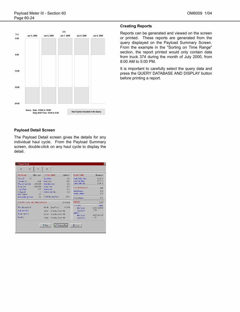
Payload Meter III - Section 60 OM6009 1/04Page 60-24
Payload Detail Screen
The Payload Detail screen gives the details for anyindividual haul cycle. From the Payload Summaryscreen, double-click on any haul cycle to display thedetail.
Creating Reports
Reports can be generated and viewed on the screenor printed. These reports are generated from thequery displayed on the Payload Summary Screen.From the example in the "Sorting on Time Range"section, the report printed would only contain datafrom truck 374 during the month of July 2000, from8:00 AM to 5:00 PM.
It is important to carefully select the query data andpress the QUERY DATABASE AND DISPLAY buttonbefore printing a report.
0:00
6:00
18:00
24:00
12:00
Jan 5, 2000 Jan 9, 2000Jan 8, 2000Jan 7, 2000Jan 6, 2000Time
Date
Query : Date: 1/5/00 to 1/8/00Daily Shift Time: 18:00 to 6:00 Haul Cycles Included in the Query
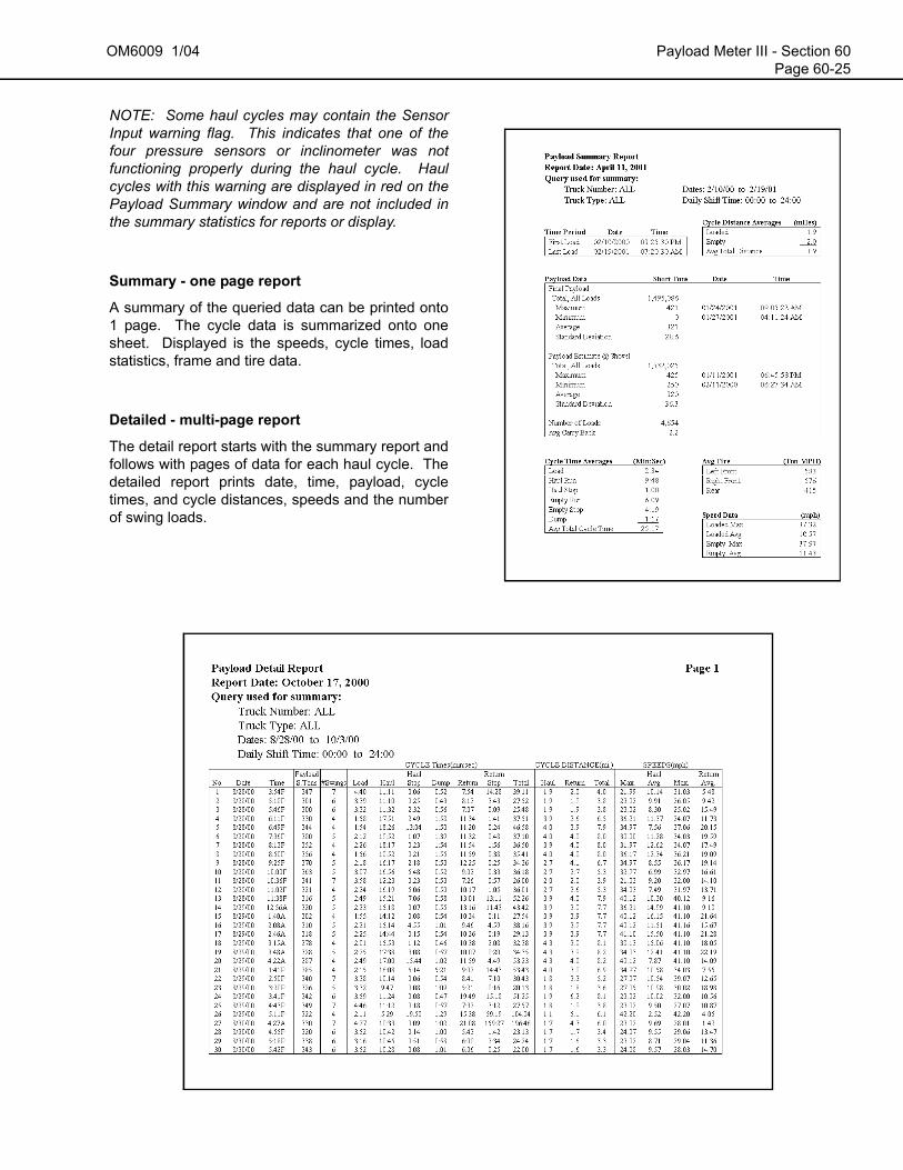
OM6009 1/04 Payload Meter III - Section 60Page 60-25
NOTE: Some haul cycles may contain the SensorInput warning flag. This indicates that one of thefour pressure sensors or inclinometer was notfunctioning properly during the haul cycle. Haulcycles with this warning are displayed in red on thePayload Summary window and are not included inthe summary statistics for reports or display.
Summary - one page report
A summary of the queried data can be printed onto1 page. The cycle data is summarized onto onesheet. Displayed is the speeds, cycle times, loadstatistics, frame and tire data.
Detailed - multi-page report
The detail report starts with the summary report andfollows with pages of data for each haul cycle. Thedetailed report prints date, time, payload, cycletimes, and cycle distances, speeds and the numberof swing loads.
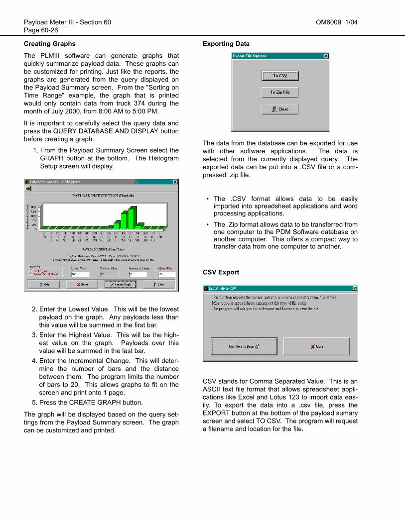
Payload Meter III - Section 60 OM6009 1/04Page 60-26
Creating Graphs
The PLMIII software can generate graphs thatquickly summarize payload data. These graphs canbe customized for printing. Just like the reports, thegraphs are generated from the query displayed onthe Payload Summary screen. From the "Sorting onTime Range" example, the graph that is printedwould only contain data from truck 374 during themonth of July 2000, from 8:00 AM to 5:00 PM.
It is important to carefully select the query data andpress the QUERY DATABASE AND DISPLAY buttonbefore creating a graph.
1. From the Payload Summary Screen select theGRAPH button at the bottom. The HistogramSetup screen will display.
2. Enter the Lowest Value. This will be the lowestpayload on the graph. Any payloads less thanthis value will be summed in the first bar.
3. Enter the Highest Value. This will be the high-est value on the graph. Payloads over thisvalue will be summed in the last bar.
4. Enter the Incremental Change. This will deter-mine the number of bars and the distancebetween them. The program limits the numberof bars to 20. This allows graphs to fit on thescreen and print onto 1 page.
5. Press the CREATE GRAPH button.
The graph will be displayed based on the query set-tings from the Payload Summary screen. The graphcan be customized and printed.
Exporting Data
The data from the database can be exported for usewith other software applications. The data isselected from the currently displayed query. Theexported data can be put into a .CSV file or a com-pressed .zip file.
• The .CSV format allows data to be easilyimported into spreadsheet applications and wordprocessing applications.
• The .Zip format allows data to be transferred fromone computer to the PDM Software database onanother computer. This offers a compact way totransfer data from one computer to another.
CSV Export
CSV stands for Comma Separated Value. This is anASCII text file format that allows spreadsheet appli-cations like Excel and Lotus 123 to import data eas-ily. To export the data into a .csv file, press theEXPORT button at the bottom of the payload sumaryscreen and select TO CSV. The program will requesta filename and location for the file.

OM6009 1/04 Payload Meter III - Section 60Page 60-27
.
Two sets of data are exported. At the top of the filewill be the haul cycle data. The columns, left to rightare:
• Truck number• Haul cycle start date• Haul cycle start time• Payload• Swingloads• Operator ID• Warning Flags• Carry Back• Total Haul Cycle time• Empty Running Time• Empty stop time• Loading time• Loaded running time• Loaded stopped time• Dumping time• Loading start time• Dumping start time• Loaded haul distance• Empty haul distance• Loaded maximum speed• Time when loaded maximum speed occurred• Empty maximum speed• Time when loaded maximum speed occurred• Maximum + frame torque• Time when the maximum + frame torque
occurred• Maximum - frame torque• Time when the maximum - frame torque occurred• Maximum sprung weight calculation• Time when the maximum sprung weight
calculation occurred• Left Front Tire-kilometer-hour• Right Front Tire-kilometer-hour• Average Rear Tire-kilometer-hour• Frame serial number
• Reserved 1-5, 7-10: These values are internalcalculations used in the continued developmentof PLMIII and should be ignored.
• Reserved 6: This value is the payload estimateat the shovel just before the truck begins tomove.
The second series of data below the haul cycle datais the alarms. The alarm columns, left to right are:
• The alarm type• The date the alarm was set• The time the alarm was set• Alarm description• The date the alarm was cleared• The time the alarm was cleared
Compressed
This export function allows the data from one laptopto be transferred to another computer. This can beuseful when a service laptop is used to downloadmultiple machines and transfer the data to a centralcomputer for analysis. This can also be used to copyhaul data from a particular truck onto a diskette foranalysis.
The file format is a compressed binary form of thedisplayed query. The file can only be imported byanother computer running the PDM Software.
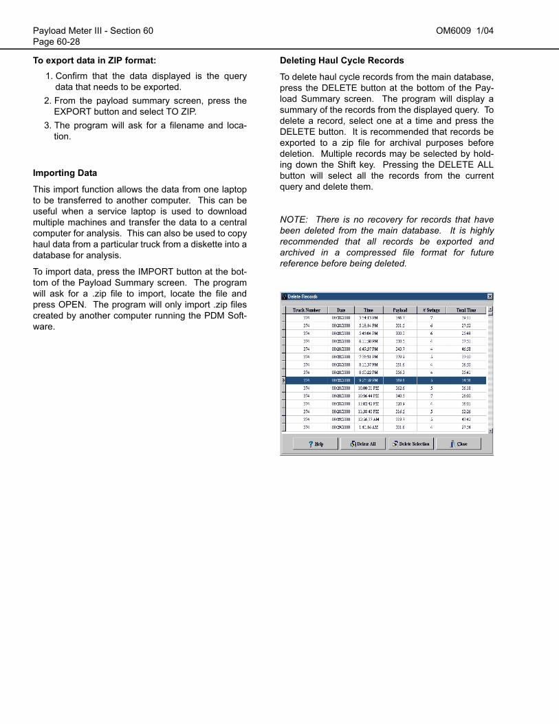
Payload Meter III - Section 60 OM6009 1/04Page 60-28
To export data in ZIP format:1. Confirm that the data displayed is the query
data that needs to be exported.2. From the payload summary screen, press the
EXPORT button and select TO ZIP.3. The program will ask for a filename and loca-
tion.
Importing Data
This import function allows the data from one laptopto be transferred to another computer. This can beuseful when a service laptop is used to downloadmultiple machines and transfer the data to a centralcomputer for analysis. This can also be used to copyhaul data from a particular truck from a diskette into adatabase for analysis.
To import data, press the IMPORT button at the bot-tom of the Payload Summary screen. The programwill ask for a .zip file to import, locate the file andpress OPEN. The program will only import .zip filescreated by another computer running the PDM Soft-ware.
Deleting Haul Cycle Records
To delete haul cycle records from the main database,press the DELETE button at the bottom of the Pay-load Summary screen. The program will display asummary of the records from the displayed query. Todelete a record, select one at a time and press theDELETE button. It is recommended that records beexported to a zip file for archival purposes beforedeletion. Multiple records may be selected by hold-ing down the Shift key. Pressing the DELETE ALLbutton will select all the records from the currentquery and delete them.
NOTE: There is no recovery for records that havebeen deleted from the main database. It is highlyrecommended that all records be exported andarchived in a compressed file format for futurereference before being deleted.
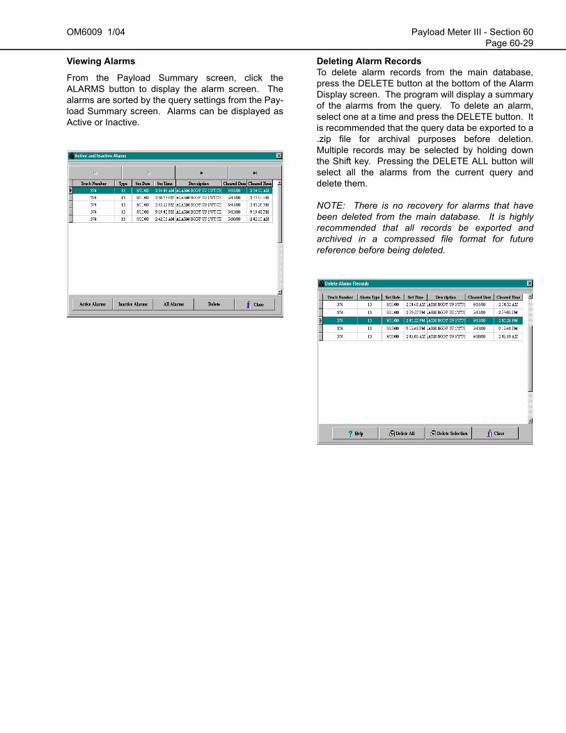
OM6009 1/04 Payload Meter III - Section 60Page 60-29
Viewing Alarms
From the Payload Summary screen, click theALARMS button to display the alarm screen. Thealarms are sorted by the query settings from the Pay-load Summary screen. Alarms can be displayed asActive or Inactive.
Deleting Alarm RecordsTo delete alarm records from the main database,press the DELETE button at the bottom of the AlarmDisplay screen. The program will display a summaryof the alarms from the query. To delete an alarm,select one at a time and press the DELETE button. Itis recommended that the query data be exported to a.zip file for archival purposes before deletion.Multiple records may be selected by holding downthe Shift key. Pressing the DELETE ALL button willselect all the alarms from the current query anddelete them.
NOTE: There is no recovery for alarms that havebeen deleted from the main database. It is highlyrecommended that all records be exported andarchived in a compressed file format for futurereference before being deleted.

Payload Meter III - Section 60 OM6009 1/04Page 60-30
NOTES
PORTIONS OF THIS PRODUCT RELATING TO PAYLOAD MEASURING SYSTEMS ARE MANUFACTURED UNDER LICENSE FROM
L.G. HAGENBUCH holder of U.S. Patent Numbers 4,831,539 and 4,839,835
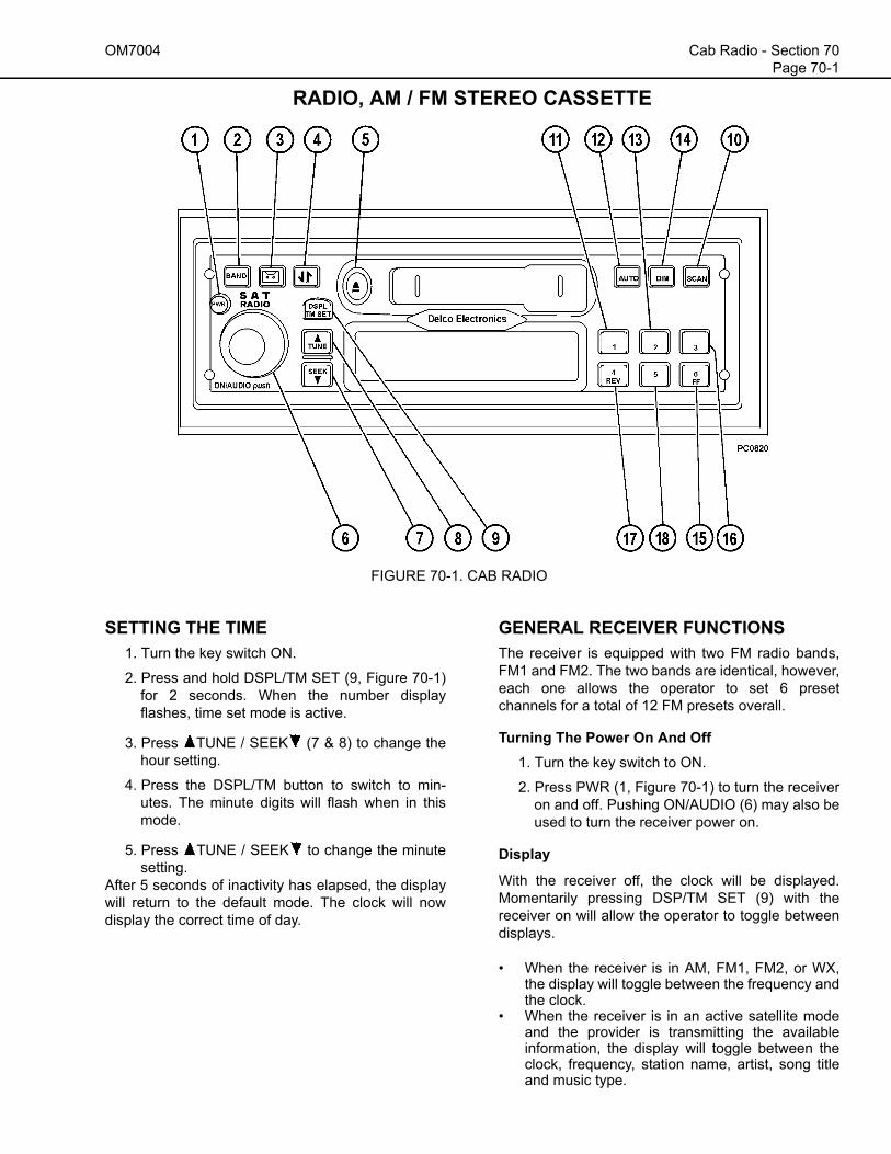
OM7004 Cab Radio - Section 70Page 70-1
RADIO, AM / FM STEREO CASSETTE
SETTING THE TIME1. Turn the key switch ON.
2. Press and hold DSPL/TM SET (9, Figure 70-1)for 2 seconds. When the number displayflashes, time set mode is active.
3. Press TUNE / SEEK (7 & 8) to change thehour setting.
4. Press the DSPL/TM button to switch to min-utes. The minute digits will flash when in thismode.
5. Press TUNE / SEEK to change the minutesetting.
After 5 seconds of inactivity has elapsed, the displaywill return to the default mode. The clock will nowdisplay the correct time of day.
GENERAL RECEIVER FUNCTIONSThe receiver is equipped with two FM radio bands,FM1 and FM2. The two bands are identical, however,each one allows the operator to set 6 presetchannels for a total of 12 FM presets overall.
Turning The Power On And Off1. Turn the key switch to ON.
2. Press PWR (1, Figure 70-1) to turn the receiveron and off. Pushing ON/AUDIO (6) may also beused to turn the receiver power on.
Display
With the receiver off, the clock will be displayed.Momentarily pressing DSP/TM SET (9) with thereceiver on will allow the operator to toggle betweendisplays.
• When the receiver is in AM, FM1, FM2, or WX,the display will toggle between the frequency andthe clock.
• When the receiver is in an active satellite modeand the provider is transmitting the availableinformation, the display will toggle between theclock, frequency, station name, artist, song titleand music type.
FIGURE 70-1. CAB RADIO
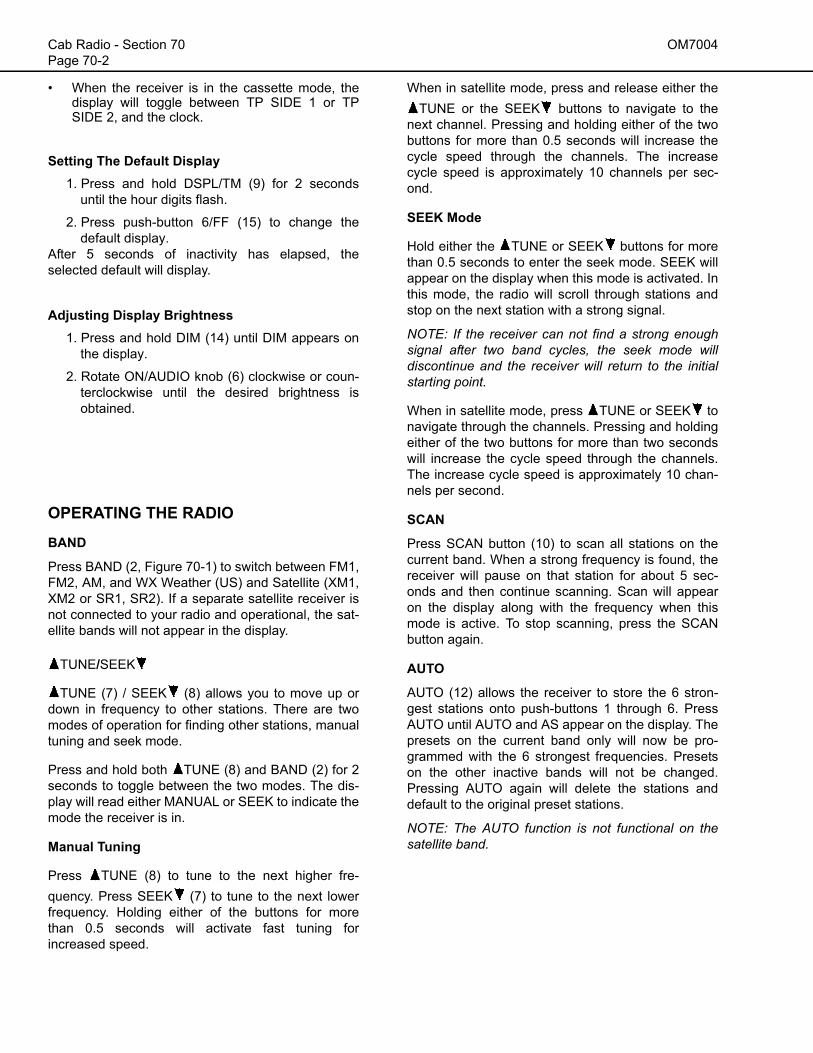
Cab Radio - Section 70 OM7004Page 70-2
• When the receiver is in the cassette mode, thedisplay will toggle between TP SIDE 1 or TPSIDE 2, and the clock.
Setting The Default Display1. Press and hold DSPL/TM (9) for 2 seconds
until the hour digits flash.
2. Press push-button 6/FF (15) to change thedefault display.
After 5 seconds of inactivity has elapsed, theselected default will display.
Adjusting Display Brightness1. Press and hold DIM (14) until DIM appears on
the display.
2. Rotate ON/AUDIO knob (6) clockwise or coun-terclockwise until the desired brightness isobtained.
OPERATING THE RADIO
BAND
Press BAND (2, Figure 70-1) to switch between FM1,FM2, AM, and WX Weather (US) and Satellite (XM1,XM2 or SR1, SR2). If a separate satellite receiver isnot connected to your radio and operational, the sat-ellite bands will not appear in the display.
TUNE/SEEK
TUNE (7) / SEEK (8) allows you to move up ordown in frequency to other stations. There are twomodes of operation for finding other stations, manualtuning and seek mode.
Press and hold both TUNE (8) and BAND (2) for 2seconds to toggle between the two modes. The dis-play will read either MANUAL or SEEK to indicate themode the receiver is in.
Manual Tuning
Press TUNE (8) to tune to the next higher fre-quency. Press SEEK (7) to tune to the next lowerfrequency. Holding either of the buttons for morethan 0.5 seconds will activate fast tuning forincreased speed.
When in satellite mode, press and release either theTUNE or the SEEK buttons to navigate to the
next channel. Pressing and holding either of the twobuttons for more than 0.5 seconds will increase thecycle speed through the channels. The increasecycle speed is approximately 10 channels per sec-ond.
SEEK Mode
Hold either the TUNE or SEEK buttons for morethan 0.5 seconds to enter the seek mode. SEEK willappear on the display when this mode is activated. Inthis mode, the radio will scroll through stations andstop on the next station with a strong signal.
NOTE: If the receiver can not find a strong enoughsignal after two band cycles, the seek mode willdiscontinue and the receiver will return to the initialstarting point.
When in satellite mode, press TUNE or SEEK tonavigate through the channels. Pressing and holdingeither of the two buttons for more than two secondswill increase the cycle speed through the channels.The increase cycle speed is approximately 10 chan-nels per second.
SCAN
Press SCAN button (10) to scan all stations on thecurrent band. When a strong frequency is found, thereceiver will pause on that station for about 5 sec-onds and then continue scanning. Scan will appearon the display along with the frequency when thismode is active. To stop scanning, press the SCANbutton again.
AUTO
AUTO (12) allows the receiver to store the 6 stron-gest stations onto push-buttons 1 through 6. PressAUTO until AUTO and AS appear on the display. Thepresets on the current band only will now be pro-grammed with the 6 strongest frequencies. Presetson the other inactive bands will not be changed.Pressing AUTO again will delete the stations anddefault to the original preset stations.
NOTE: The AUTO function is not functional on thesatellite band.
OM7004 Cab Radio - Section 70Page 70-3
ADJUSTING THE RECEIVER SETTINGSVOLUME: Rotate ON/AUDIO (6, Figure 70-1) knobclockwise to increase the volume and counter-clock-wise to decrease the volume. VOL will be displayedalong with the volume level.
BASS: Push and release ON/AUDIO (6) knob untilBASS and the current bass level is displayed. Rotatethe knob clockwise to increase the bass and counter-clockwise to decrease the bass.
TREBLE: Push and release ON/AUDIO (6) knobuntil TREB and the current treble level is displayed.Rotate the knob clockwise to increase the treble andcounter-clockwise to decrease the treble.
FADE: Push and release ON/AUDIO (6) knob untilFADE and the current level is displayed. Rotate theknob clockwise to move the sound to the front speak-ers and counter-clockwise to move the sound to therear speakers.
BALANCE: Push and release ON/AUDIO (6) knobuntil BAL and the present level is displayed. Rotatethe knob clockwise to move the sound to the rightspeakers and counter-clockwise to move the soundto the left speakers.
SPEAKER: Push and release ON/AUDIO (6) knobuntil SPKR and the current setting is displayed.Rotate the ON/AUDIO knob to select 2-speaker or 4-speaker operation. When 2-speaker operation active,the rear speakers are muted and the FADE optionwill not appear on the menu.
PROGRAMMING PRESET STATIONSPresets are stations that are stored on each of the 6push-buttons. After a station has been programmedinto one of the preset buttons, pushing the presetprovides a quick return to that station. The six but-tons can each store a preset channel per band.Perform the following steps for programming presets:
1. Turn the receiver ON.2. Select the band and the desired station.3. Press and hold one of the six push-buttons for
at least 2 seconds. During the 2 second period,receiver output will be muted and the push-but-ton number will not show on the display. Whenthe station has been committed to memory, theaudio and the preset icon will return.
4. Repeat steps 1 through 3 for the remainingavailable presets.
OPERATION OF THE WEATHERBAND (U.S.)NOAA - Weather Radio is a service of the NationalWeather Service. It provides continuous broadcastsof the latest weather information directly from theNational Weather Service offices. Taped weathermessages are repeated every four to six minutes andare routinely revised every one to three hours, ormore frequently if needed. Most of the stations oper-ate 24 hours, daily.
The weather for the area you are in may be found onone of 7 stations. When in the Weatherband mode,the display will show the WX icon and CHAN # toindicate the channel. The channel may be adjustedthrough the TUNE /SEEK buttons, and may bepreset as in the radio mode. The frequency associated with each channel is asfollows:
1. 162.550 MHz 5. 162.450 MHz 2. 162.400 MHz 6. 162.500 MHz 3. 162.475 MHz 7. 162.525 MHz 4. 162.425 MHz
The National Weather Service operates approxi-mately 372 stations. Close to 90 percent of thenation's population is within the listening range of aNOAA Weather Radio broadcast.
Cab Radio - Section 70 OM7004Page 70-4
SATELLITE RADIOIn order to use the satellite radio function on yourradio, a subscription must be ordered from a pro-vider. There are two providers in the U.S. currently,XM and Sirius Satellite Radio. When a subscription isordered, an additional receiver and antenna will needto be obtained from your provider.
To activate the external satellite receiver, you mustsupply the provider with your Electronic Serial Num-ber (ESN). To find the ESN, first install the satellitereceiver per instructions from the your provider. Next,follow the instructions below.
XM Satellite Radio:1. Turn both the radio and the satellite receiver on.
Press the BAND button on the radio and selecteither XM1 or XM2.
2. Tune your satellite receiver to channel 0 to seethe ESN display.
Record the ESN.
The display will return to the default setting after5 seconds.
Sirius Satellite Radio:1. Turn the radio on and with the display showing
the clock, press and hold the DSPL/TM SETbutton until the hours segment is flashing.
2. Press the BAND button and the ESN will be dis-played.
Record the ESN.
The display will return to the default setting after5 seconds.
NOTE: Only one satellite receiver can be installedand connected to your receiver at one time.
NOTE: Obstructions in the satellite signal may impairyour satellite radio reception. Contact your providerfor satellite radio reception problems.
Operating Satellite Radio1. Use the BAND button to select the proper satel-
lite radio band. (XM1, XM2, SR1, SR2)
2. Use the TUNE and SEEK buttons to navi-gate through the channels.
Program Type Search (PTY)
XM and Sirius both allow you to search by musictype. Program Type Search (PTY) allows you to per-form a music search by type. Perform the followingsteps in order to do a PTY search.
1. Press SCAN and push-button 1 at the sametime. PTY will appear on the display.
2. Continue to press push-button 1 until thedesired genre of programming is displayed.
3. Once the desired genre has been selected,press the TUNE and SEEK buttons to scrollthrough the different channels in that genre.Station names will appear on the display asyour scroll.
You may also scan through the channels usingthe scan feature. Press the SCAN button tobegin scanning the channels. Press the SCANbutton again to stop at the desired channel.
OM7004 Cab Radio - Section 70Page 70-5
CASSETTE PLAYER The cassette player that the radio is equipped withworks best with cassettes that range from 30 to 90minutes long. Cassettes that are longer than 90 min-utes have thinner tape, and do not work well in thismodel cassette player. It is also important to only use cassettes that are ingood condition. Cassettes that are dirty, damaged, orhave been exposed to excessive heat and/or sunlightcould cause damage to the cassette player and pos-sible failure.The cassette player is equipped with automaticequalization and metal tape sensing functions. An Mwill appear on the display when a metal tape issensed.Cleaning the cassette player is a recommendedmaintenance item. It should be performed at 35 hour(cassette play) intervals. Failure to clean the cassetteplayer may diminish sound quality and cause cas-sette player failure.
Playing A Cassette1. Turn the receiver ON.2. Insert a cassette into the player. The cassette
icon will appear on the display. The tape willbegin to play when the icon appears.
Press button (3, Figure 70-1) to changefrom the radio to a cassette. TP SIDE 1 or TPSIDE 2 will appear on the display depending onwhich side of the cassette is currently beingplayed. If a cassette is not loaded in the player,NO TAPE will appear on the display.
NOTE:A tape may be inserted when the receiver isoff by pressing the eject button and inserting the tapewithin 25 seconds.
Cassette Functions
4/REV (17): This button rewinds the cassette. Thecassette will continue to rewind until the button ispressed again, or until the cassette reaches the endof the tape. <REW will appear on the display as thecassette is rewinding.
6/FF (15): This button fast forwards the cassette. Thecassette will continue to fast forward until the buttonis pressed again, or until the cassette reaches theend of the tape. FWD> will appear on the display asthe cassette is fast forwarding.
Eject (5): Press this button to eject the cassettefrom the player. When the eject button is held, it actsas a stop button.
(4): This button causes the cassette player toreverse directions and play the opposite side of thecassette. Pressing the button a second time willreverse the cassette back to the original side.
NOTE: The cassette will automatically flip to theopposite side when the end of the tape is reached.
PROGRAMMABLE EJECT DEFAULTThe cassette player has been pre-programmed toreturn to the radio after a tape has been ejected. Thisdefault may be changed to an “eject audio mute”mode. This mode will mute the radio after a cassettehas been ejected. When this occurs, “NO TAPE” willappear on the display and the radio will remainmuted until BAND (2) is pressed. Pressing this buttonwill enable the radio.
Perform the following steps to change the ejectdefault mode:
1. Press and hold DSP/TM SET (9, Figure 70-1)for at least 2 seconds until the hour digits flash.
2. Press button (3) to toggle between“P.PLAY” and “EJMUTE”. After 5 seconds ofinactivity, the receiver will return to the defaultdisplay.
Cab Radio - Section 70 OM7004Page 70-6
Bad Tape Detect
If the receiver detects a bad cassette, “BAD TAPE”will appear on the display, and the tape will beejected. If this occurs, the cassette should beremoved from the player and should not be re-inserted.
If it is desired to use a cleaning tape or a CD adapterin the cassette player, the bad tape detector must beturned OFF. Perform the following steps in order todisable this mode:
1. Turn the receiver off and turn the key switch toOFF.
2. Press and hold button (3) for 5 seconds.“BAD TAPE DETECT OFF” will appear on thedisplay. When this is displayed, the detectorhas been disabled.
Repeat this procedure to reactivate the badtape detector. “BAD TAPE DETECT ON” willappear on the display after the detector hasbeen activated.
CASSETTE PLAYER CLEANINGAfter 35 hours of cassette play, the display will readTP CLEAN for 5 seconds. This indicates that it istime to clean the cassette player.
1. Turn the key switch to ON, and turn the receiveroff.
2. Disable BAD TAPE DETECT mode. Press and
hold button (3, Figure 70-1) for 5 seconds.“BAD TAPE DETECT OFF” will appear on thedisplay. When this is displayed, the detectorhas been disabled.
3. Turn the receiver on.4. Insert a wet-type, non-abrasive, scrubbing cas-
sette cleaner. Follow the instructions providedwith the cleaner.
5. Reset the clean tape timer. With the receiveron, press and hold the eject button for 5 sec-onds. TP CLEAN will appear on the display andthe tape icon will flash after 3 seconds haselapsed. After 5 seconds CLN RST will appearon the display. When this occurs, the clean tapetimer will be reset to zero hours. If the buttonwas released before CLN RST was displayed,the timer will not be reset.

NOTES:

www.komatsuamerica.com
®
Komatsu America Corp.2300 N.E. Adams Street Peoria, IL 61639 Phone: 309-672-7577 Fax: 309-672-7072
Copyright 2004 KomatsuPrinted in U.S.A.