Embed Size (px)
Citation preview

©Copyright 2006 – Sonic Air Systems, Inc.
Operation and Maintenance Manual
Sonic 150 / 150C
Sonic Air Systems 1050 Beacon Street
Brea, California 92821 Tel: 714-255-0124 Fax: 714-255-8366
www.sonicairsystems.com
©Copyright 2006 – Sonic Air Systems, Inc.
Operation and Maintenance Manual
Sonic 150 / 150C
O&M-150
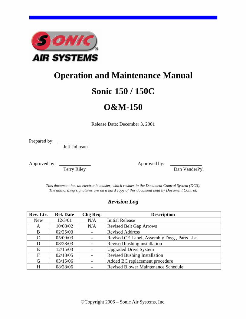
Release Date: December 3, 2001 Prepared by: _____________ Jeff Johnson Approved by: _____________ Approved by: _____________ Terry Riley Dan VanderPyl
This document has an electronic master, which resides in the Document Control System (DCS). The authorizing signatures are on a hard copy of this document held by Document Control.
Revision Log
Rev. Ltr. Rel. Date Chg Req. Description
New 12/3/01 N/A Initial Release A 10/08/02 N/A Revised Belt Gap Arrows B 02/25/03 - Revised Address C 05/09/03 - Revised CE Label, Assembly Dwg., Parts List D 08/28/03 - Revised bushing installation E 12/15/03 - Upgraded Drive System F 02/18/05 - Revised Bushing Installation G 03/15/06 - Added BC replacement procedure H 08/28/06 - Revised Blower Maintenance Schedule
www.sonicairsystems.com
Page i ©Copyright 2006 – Sonic Air Systems, Inc.
Table of Contents 1 Sonic 150 / Sonic 150C.......................................................................................................................................1
1.1 Introduction ................................................................................................................................................1 1.2 Blower Performance...................................................................................................................................1 1.3 Product Profile............................................................................................................................................2 1.4 Typical Applications ..................................................................................................................................3
2 Initial Inspection ................................................................................................................................................4
3 Safety Instructions .............................................................................................................................................5 3.1 Electrical.....................................................................................................................................................5 3.2 Mechanical .................................................................................................................................................5
4 Installation and Adjustments............................................................................................................................6 4.1 Lifting and Handling ..................................................................................................................................6 4.2 Blower Location .........................................................................................................................................6 4.3 Belt Installation ..........................................................................................................................................8 4.4 Blower Head Mounting Adjustment.........................................................................................................11 4.5 Retro Kit Installation (Assemble Sonic blower to existing motor) ..........................................................15
5 Electrical Wiring, and Start-Up .....................................................................................................................18 5.1 Motor Wiring............................................................................................................................................18
6 Blower Specifications.......................................................................................................................................19 6.1 Blower Specification Sheet ......................................................................................................................19 6.2 Assembly Drawing ...................................................................................................................................20 6.3 Parts List...................................................................................................................................................21 6.4 Motor Reference.......................................................................................................................................28 6.5 Pulley / Belt Cross Reference...................................................................................................................28
7 Periodic Maintenance ......................................................................................................................................29 7.1 Maintenance Schedule..............................................................................................................................29 7.2 Torque Specifications...............................................................................................................................29 7.3 Belt Replacement Procedure ....................................................................................................................29 7.4 Belt Tensioner Service .............................................................................................................................32 7.5 Bearing Cartridge Replacement Procedure ..............................................................................................36 7.6 Required Tools .........................................................................................................................................37 7.7 Bearing Cartridge Replacement Procedure ..............................................................................................37 7.8 Recommended Spares ..............................................................................................................................41
8 Troubleshooting ...............................................................................................................................................42
9 Performance Guarantee ..................................................................................................................................43
10 Warranty Policy ...............................................................................................................................................44
11 24/7/365 Service Program................................................................................................................................45
12 Sonic Repair Policy ..........................................................................................................................................46

www.sonicairsystems.com
Page ii ©Copyright 2006 – Sonic Air Systems, Inc.
Table of Figures Figure 1 - Sonic 150 ......................................................................................................................................................1 Figure 2 - Sonic 150C ...................................................................................................................................................1 Figure 3 - Sonic Nameplate ...........................................................................................................................................4 Figure 4 – Blower Serial Number..................................................................................................................................4 Figure 5 - Blower Lifting Point .....................................................................................................................................6 Figure 6 - Remove Belt Guard ......................................................................................................................................9 Figure 7 - Install Belt.....................................................................................................................................................9 Figure 8 – Verify Belt Gap............................................................................................................................................9 Figure 9 - Loosen Bracket Bolts....................................................................................................................................9 Figure 10 – Adjust Belt Gap to ¾”..............................................................................................................................10 Figure 11 - Blower Rotations ......................................................................................................................................11 Figure 12 - Remove Belt Guard ..................................................................................................................................13 Figure 13 - Remove Belt .............................................................................................................................................13 Figure 14 - Remove Motor Pulley...............................................................................................................................13 Figure 15 - Remove Bracket Hardware.......................................................................................................................13 Figure 16 - Rotate Bracket ..........................................................................................................................................14 Figure 17 - Install Bracket Hardware ..........................................................................................................................14 Figure 18 - Remove Blower Hardware........................................................................................................................14 Figure 19 - Move Water-Cooling Plugs ......................................................................................................................14 Figure 20 - Reinstall Blower Head ..............................................................................................................................14 Figure 21 - Reinstall Belt.............................................................................................................................................14 Figure 22 - Adjust Belt Gap to 3/4".............................................................................................................................14 Figure 23 - Final Position ............................................................................................................................................14 Figure 24 - Install Uni-mounts ....................................................................................................................................16 Figure 25 - Mount Bracket to Motor ...........................................................................................................................16 Figure 26 - Prepare Bushing........................................................................................................................................16 Figure 27 - Install Bushing ..........................................................................................................................................16 Figure 28 – Install Bushing Hardware.........................................................................................................................16 Figure 29 - Bushing Installation ..................................................................................................................................16 Figure 30 – Install Set Screw.......................................................................................................................................16 Figure 31 - Install Motor Pulley ..................................................................................................................................17 Figure 32 - Install Belt.................................................................................................................................................17 Figure 33 - Set Belt Gap to ¾” ....................................................................................................................................17 Figure 34 - Check Alignment ......................................................................................................................................17 Figure 35 - Motor Rotation Sticker .............................................................................................................................18 Figure 36 - Remove Belt Guard ..................................................................................................................................30 Figure 37 - Remove Existing Belt ...............................................................................................................................30 Figure 38 - Install New Belt ........................................................................................................................................31 Figure 39 – Verify Belt Gap........................................................................................................................................31 Figure 40 - Loosen Bracket Hardware ........................................................................................................................31 Figure 41 - Adjust Belt Gap to ¾” ..............................................................................................................................31 Figure 42 - Remove Belt Guard ..................................................................................................................................33 Figure 43 - Remove Belt .............................................................................................................................................33 Figure 44 - Remove Motor Pulley...............................................................................................................................33 Figure 45 - Remove Bolt .............................................................................................................................................33 Figure 46 - Remove Belt Tensioner ............................................................................................................................34 Figure 47 - Caution Loose Springs..............................................................................................................................34 Figure 48 - Correct Position ........................................................................................................................................34 Figure 49 - Verify Belt Gap.........................................................................................................................................34 Figure 50 - Loosen Bracket Hardware ........................................................................................................................35 Figure 51 - Adjust Belt Gap to 3/4".............................................................................................................................35 Figure 52 - Remove Belt Guard ..................................................................................................................................38 Figure 53 - Remove Belt .............................................................................................................................................38 Figure 54 – Remove Water Cooling Tubing ...............................................................................................................38

www.sonicairsystems.com
Page iii ©Copyright 2006 – Sonic Air Systems, Inc.
Figure 55 – Remove Filter or Inlet Screen ..................................................................................................................38 Figure 56 – Remove Cover..........................................................................................................................................39 Figure 57 – Remove Impeller ......................................................................................................................................39 Figure 58 – Remove Blower Pulley ............................................................................................................................39 Figure 59 – Remove Thermocouple ............................................................................................................................39 Figure 60 – Remove Compression Fitting...................................................................................................................40 Figure 61 – Remove Bearing Cartridge Hardware ......................................................................................................40 Figure 62 – Remove Bearing Cartridge.......................................................................................................................40 Figure 63 – Blower w/ Bearing Cartridge Removed ...................................................................................................40

www.sonicairsystems.com
Page 1 ©Copyright 2006 – Sonic Air Systems, Inc.
1 Sonic 150 / Sonic 150C
Figure 1 - Sonic 150
Figure 2 - Sonic 150C
1.1 Introduction Thank you for the recent purchase of a Sonic 150 or Sonic 150C centrifugal blower or retro-kit. Sonic Air Systems is confident that the blower unit is the best available in this performance range. Sonic manufactures blowers using the finest components available, assembles using only highly trained and qualified personnel, and inspects each unit 100% for quality and performance. The following manual is intended to:
• Identify safety hazards • Familiarize personnel with the equipment performance • Demonstrate typical installation and usage • Identify maintenance schedule and typical spare components • Provide Sonics’ Performance Guarantee and Warranty information
1.2 Blower Performance
• The Sonic 150 series blower is a single stage centrifugal blower and has been designed in accordance with fan engineering laws. Horsepower demand increases in proportion to increased air volume (motor amperage draw increases). As the air volume decreases (valve closes or filter clogs), the amp draw decreases. Always check a fully installed system to ensure that the motor is not overloaded.

www.sonicairsystems.com
Page 2 ©Copyright 2006 – Sonic Air Systems, Inc.
• Sonic air blowers have some of the largest turndown ratios of any blower in their performance range. At 10:1, a Sonic 150’s range is from 120 cfm 57 (lps) to 1,200 cfm (566 lps) without overheating or surging. Outside of those ranges the air surging is mild and continuous operation may shorten the bearing life.
• The blower inlet must also be hose coupled to an inlet filter-silencer, inlet air safety screen or piped to a delivery system. Sonic inlet filter-silencers should be used in every application where the inlet air is not piped directly to the blower inlet. Sonic standard filters are rated at 2 microns with a paper element or 5 microns with a polyester element. Inlet air temperature must not exceed 125°F (52°C) unless a Sonic 150C water-cooled unit is used. If the blower is in an enclosed space and the inlet air is piped from another area, make sure that the ambient temperature around the blower / motor does not exceed 110°F (43°C). When air is re-circulated from an air knife zone, in-line filters and water separators must be used to prevent water from entering the blower.
• The blower outlet must always be hose coupled to a discharge silencer, system piping, or otherwise directed away from personnel. Discharged air should be silenced to levels as required by applicable occupational safety standards or corporate standards as applicable. In order to minimize pressure drop and noise transmission, Sonic recommends using smooth bore tubing (hard plastic or metal).
• Flex hose can induce a large pressure drop and should only be used when absolutely necessary. Flex hose should be rated to handle a pressure of 10 psig (0.7 bar) at 200°F (93°C). Flex hose can be used for connecting misaligned piping and bend radii that do not match standard elbows. Be aware that flex hose can collapse inside and should be inspected if flow problems occur. Short rubber sleeves with band clamps are standard for blower and piping connections.
• Sonic butterfly valves have a wafer design that is designed to regulate flow, but will not seal when closed. Air will always leak around the wafer to help minimize blower cavitations.
• The Patent Pending Sonic Belt Tensioner is used to maintain a constant low tension on the drive belt and reduces the maintenance schedule for the blower unit. Belt life is optimized and belt replacement typically takes only 5 to 10 minutes to perform.
• Typical blower noise is approximately 80db to 95db. Sonic Blower Acoustical Enclosures can be used to reduce blower noise to within 75 db to 85 db depending on the blower model. Additional noise reduction is available; contact Sonic for details.
1.3 Product Profile
The Sonic 150 blower with the Sonic Automatic Belt Tensioning assembly requires no periodic belt adjustment. The blower shaft and impeller assembly is supported by two duplex pair (4 bearings) ABEC 9 permanently greased packed bearings. With operating speeds of 11,000 to 20,000 RPM, a single Sonic 150 head assembly can be powered by a 15 to 25 horsepower (11.2 to 18.6 kW) motor. The inter-connecting support bracket

www.sonicairsystems.com
Page 3 ©Copyright 2006 – Sonic Air Systems, Inc.
joining the blower and motor has a belt guard completely enclosing the drive assembly and completing this integral design.
With air / gas delivery up to 1,200 CFM (566 lps), this unit is well suited for any application with pressures to 4.5 psi (0.31 bar). As a result of the high-speed operation, the total envelope of the blower / motor assembly is one of the most compact and lightweight within its performance range.
1.4 Typical Applications The following is a list of typical applications for using a Sonic 150 centrifugal blower assembly. This is only a partial list of the possible uses for supplying low cost, clean air to a particular application. Please consult a Sonic Application engineer to design a system to meet any request.
Parts drying Engine exhaust sampling Hydrocarbon vapor recovery Environmental test chambers Gas boosting Tank / Pond aeration Concrete grinding vacuum Gas meter testing Cooling Vacuum hold down Oil spill containment booms Air bearings Special applications and options are available for the Sonic 150 blower unit: Corrosion resistant electroplating Air flow control valves 316 Stainless Steel Material Option Acoustical enclosure Welded inlet and outlet flanges In-Line filters and water separators Water cooling of the bearing housing Filter Silencers Operation to 400°F inlet air temperature Explosion Proof motors Thermocouple monitoring of bearings Wash Down duty motors Discharge silencers Premium Efficiency (PE) motors IEC motor compatibility Hydraulic motors Sonic also provides a full line of air / gas handling accessories: Complete drying systems Air wipe collars Air blowers from 3 to 50 horsepower HEPA filters to 1,000 CFM High efficiency aluminum air knives Acoustical enclosures High efficiency stainless steel air knives Piping accessories Sonic services four main industries: Food and Beverage Wire and Cable Electronics Metal and Sheet Fabricators Please contact a local Sonic representative or a Sonic application engineer to discuss any special considerations or applications.

www.sonicairsystems.com
Page 4 ©Copyright 2006 – Sonic Air Systems, Inc.
2 Initial Inspection Upon receipt of your Sonic Air Centrifugal Blower, make sure that all components listed on the packing slip are present. Check to see that the serial number on the blower housing matches the packing slip (See Figure 4). Inspect the blower / motor to ensure that they are mounted with the correct outlet position and that the motor is the correct horsepower, voltage and enclosure. If you have any shortages, discrepancies, or shipping damage, please call your Sonic Distributor or Sonic Air Systems immediately.
Figure 3 - Sonic Nameplate
The serial number of the blower identifies the blower model, pulley size, belt size, mounting position, and the motor specifications. Please use this number for any correspondence with the Sales / Customer Service Department at Sonic Air Systems.
Blower Serial Number
Figure 4 – Blower Serial Number
Sonic Nameplate
Sonic Serial Number
Identification Grooves

www.sonicairsystems.com
Page 5 ©Copyright 2006 – Sonic Air Systems, Inc.
3 Safety Instructions
3.1 Electrical
• Always use qualified electrical and mechanical personnel for installation and maintenance of Sonic air blowers.
• No work should be performed on a Sonic air blower until the power has been turned off and an isolation device has been applied. Disconnect the electrical power at the motor starter, fuse box, or circuit breaker before working on the blower / motor. Double check to be sure that the power is off and that it cannot be turned on while you are working on the blower / motor assembly.
• Use proper electrical installation, wiring, and controls consistent with local and national electrical codes. A lockable isolation switch should be provided.
• Refer to the motor nameplate data for the proper power supply requirements. Be sure the junction box connections are tight and well insulated to prevent shorts and to assure maximum protection against moisture.
3.2 Mechanical
• Never run the Sonic air blower without the belt guard installed. • Never run the Sonic air blower with the outlet open to atmosphere as this can cause the
motor to overload. • Never run the Sonic air blower with the inlet open to atmosphere. Always connect your
system piping, Sonic inlet filter, or Sonic Inlet safety screen to the blower inlet to prevent personal injury or damage to the blower.
• Keep tools, clothing and hands away from rotating or moving parts while the unit is running.
• Use safety glasses when working around the blower / motor and / or air knife assembly while the system is running.
• Always use proper lifting techniques and equipment. • Observe good safety habits at all times and use care to avoid injury to personnel and
damage to the equipment.
www.sonicairsystems.com
Page 6 ©Copyright 2006 – Sonic Air Systems, Inc.
4 Installation and Adjustments The following steps and procedures detail the installation and setup of a typical blower assembly. Disassembly of a blower unit is the opposite of the assembly procedure.
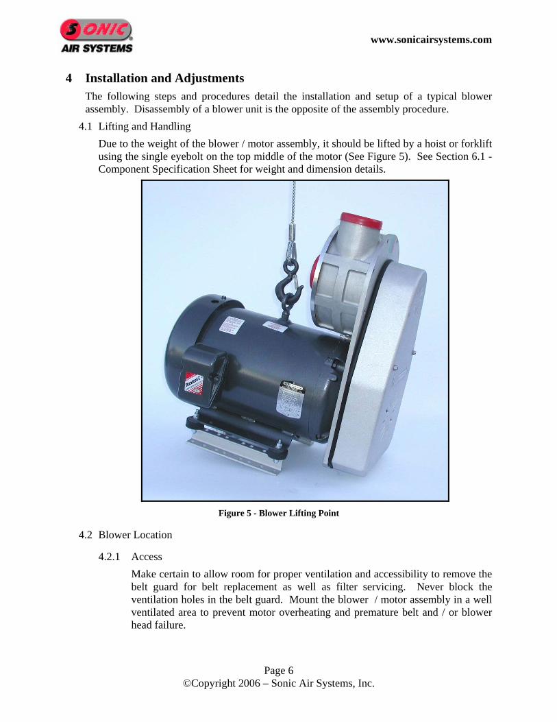
4.1 Lifting and Handling Due to the weight of the blower / motor assembly, it should be lifted by a hoist or forklift using the single eyebolt on the top middle of the motor (See Figure 5). See Section 6.1 - Component Specification Sheet for weight and dimension details.
Figure 5 - Blower Lifting Point
4.2 Blower Location
4.2.1 Access Make certain to allow room for proper ventilation and accessibility to remove the belt guard for belt replacement as well as filter servicing. Never block the ventilation holes in the belt guard. Mount the blower / motor assembly in a well ventilated area to prevent motor overheating and premature belt and / or blower head failure.

www.sonicairsystems.com
Page 7 ©Copyright 2006 – Sonic Air Systems, Inc.
4.2.2 Temperature The blower / motor assembly must be placed in an area that prevents hard freezes or overheating. Ambient temperature conditions should range from a low of +10°F (-12°C) to +110°F (43°C). The blower / motor assembly is suitable for outdoor locations, but care should be taken to protect the equipment from temperature extremes, direct exposure to the sun, rain, snow, and dust so as to extend the service life of the blower, motor, and filter. The blower / motor assembly, while running, can increase the ambient temperature above 110°F (43°C). Always check the running ambient temperature and do not operate above 110° (43°C).
4.2.3 Moisture and Debris Sonic air blowers have a high-speed belt drive, close tolerance components and precision bearings. Do not put the blower where it will be sprayed from a washing / rinsing zone, from over-spray from an air knife or where dust, dirt, or other debris will attack the drive belt or clog the filter. If the filter needs cleaning or replacing more than one time each month, the blower or filter should be moved to a cleaner, dryer area. A Sonic acoustical blower enclosure will also ensure safe operation.
4.2.4 Wash Down In factory locations subject to high-pressure water or caustic wash down cycles, the blower / motor unit must be protected or relocated to prevent damage. Raising the blower 1-2 feet (0.3 to 0.6 meters) above the wash zone is recommended. Wash down duty motors and corrosive resistant blower coatings are available to allow full exposure should it be needed.
4.2.5 Explosive Environments The Sonic 150 centrifugal blower is made from non-sparking aluminum and therefore is suitable for explosive gases and explosive environments. Special explosion proof motors can also be included for hazardous duty.
4.2.6 Corrosive Environments The Sonic 150 blower can be protected with special coatings for protection in corrosive environments. Protection level and life of blower is dependent on the type of chemical and the concentration level.
4.2.7 Vibration Due to the low vibration level of the Sonic air blowers, they can be bolted to any type of foundation or framework without transmitting any significant vibration. Sonic provides four rubber isolation mounts on most assemblies to prevent other equipment vibration from damaging the blower bearings.
4.2.8 Water Cooling Circuit If the inlet air / gas is piped directly to the blower inlet, and the temperature is over 125°F (52°C), a water-cooled blower head must be used to protect the shaft bearings. The exact water temperature and flow required in the cooling circuit

www.sonicairsystems.com
Page 8 ©Copyright 2006 – Sonic Air Systems, Inc.
will vary with each blower configuration and application. Although water demand for the blower head varies, the common design point in all applications is that the water exiting from the cooling circuit should never exceed 100°F (38°C). Typical water demand will range from ¼ to ¾ gallons per minute (1 to 3 liters per minute) if using tap water (approximately 65°F (18°C)) and will be significantly lower if chilled water is used.
4.2.9 Thermocouple Option All Sonic 150 blower heads can be ordered with a thermocouple option. The thermocouple is in direct contact with the shaft bearing and continuously monitors the temperature of the bearing. Continuous monitoring of the blower head bearing temperature can indicate an imminent bearing failure (See Section 12 for Sonics’ repair policy). Predicting and anticipating a bearing failure may save costly equipment and / or line down time.
4.3 Belt Installation Sonic ships all new systems with the drive belt removed. This is to assure that the electrical starter, soft start and wiring is correct before the blower is started. See Section 5.1 for motor wiring instructions and verify that the wiring and blower rotation is correct before installation of the drive belt. 4.3.1 Tools Required
Description Qty. Description Qty. 1/2 inch socket 1 #3 Drive Extension 1 9/16 inch box-end wrench 1 ¾ inch deep socket (optional) 1 3/8 inch ratchet driver 1 Rubber Mallet (optional) 1
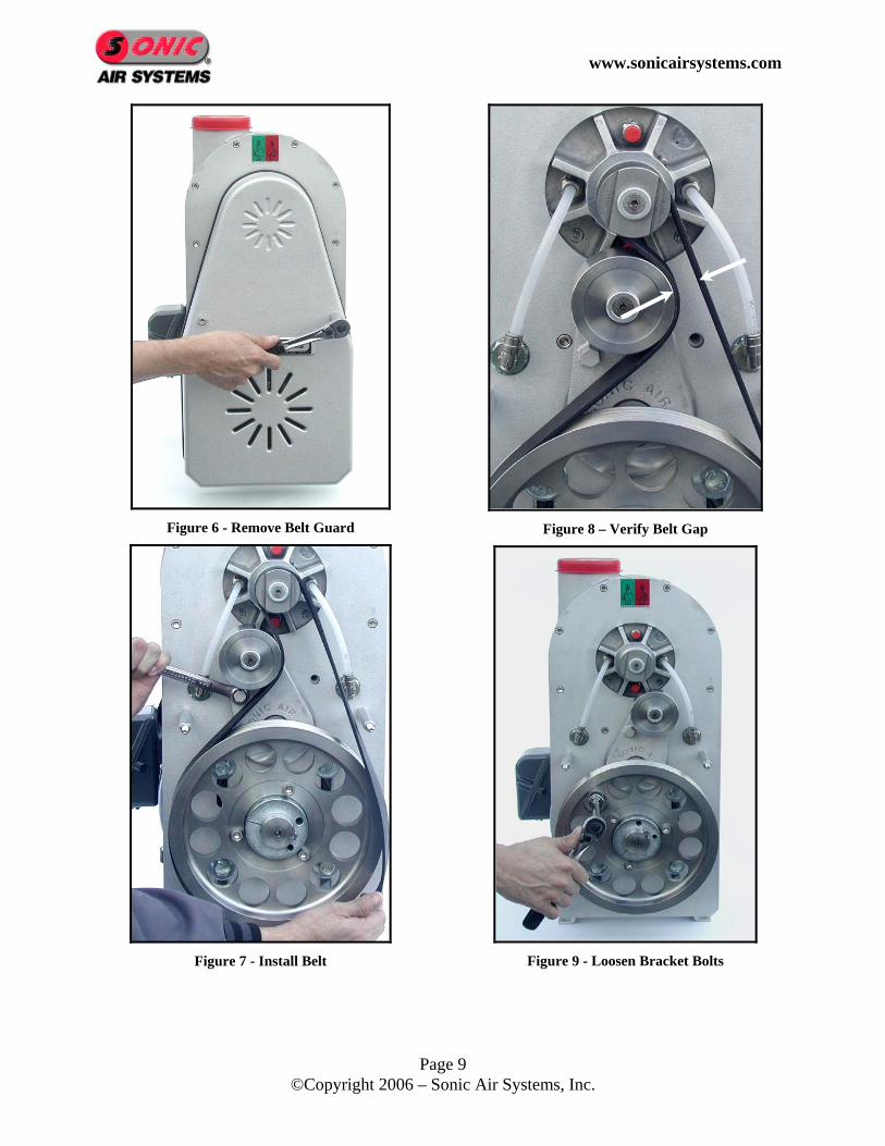
4.3.2 Belt Installation Procedure 1. Remove the belt guard using the 1/2 inch socket. (See Figure 6) 2. Using the 9/16 inch box-end wrench, rotate the belt tensioner arm counter
clockwise (CCW). At the same time wrap the belt around the blower pulley, then along the right side of the idler pulley, and finally around the motor pulley. (See Figure 7)
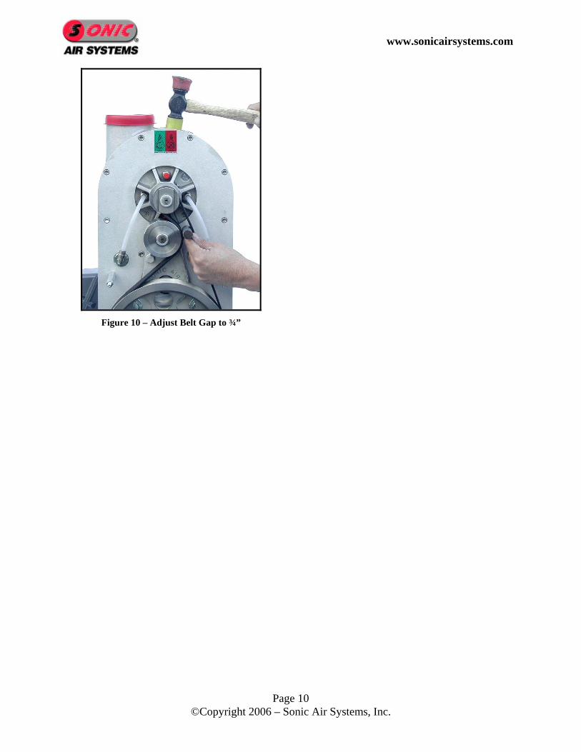
3. Slowly rotate the motor pulley to make sure the belt is seated in the grooves. 4. Verify that the belt gap is approximately ¾ inch ±1/16 inch (Factory Set). (See
Figure 8) 5. If a ¾ inch belt gap was not achieved, use a ¾ inch deep socket to loosen the
bracket mounting screws behind the motor pulley and slide the bracket. (See Figure 9 and Figure 10)
6. Using the 1/2 inch socket, reinstall the belt guard.
www.sonicairsystems.com
Page 9 ©Copyright 2006 – Sonic Air Systems, Inc.
Figure 6 - Remove Belt Guard
Figure 7 - Install Belt
Figure 8 – Verify Belt Gap
Figure 9 - Loosen Bracket Bolts
www.sonicairsystems.com
Page 10 ©Copyright 2006 – Sonic Air Systems, Inc.
Figure 10 – Adjust Belt Gap to ¾”
www.sonicairsystems.com
Page 11 ©Copyright 2006 – Sonic Air Systems, Inc.
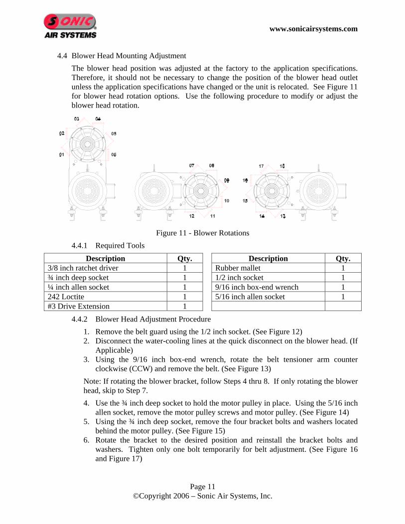
4.4 Blower Head Mounting Adjustment The blower head position was adjusted at the factory to the application specifications. Therefore, it should not be necessary to change the position of the blower head outlet unless the application specifications have changed or the unit is relocated. See Figure 11 for blower head rotation options. Use the following procedure to modify or adjust the blower head rotation.
Figure 11 - Blower Rotations
4.4.1 Required Tools Description Qty. Description Qty.
3/8 inch ratchet driver 1 Rubber mallet 1 ¾ inch deep socket 1 1/2 inch socket 1 ¼ inch allen socket 1 9/16 inch box-end wrench 1 242 Loctite 1 5/16 inch allen socket 1 #3 Drive Extension 1
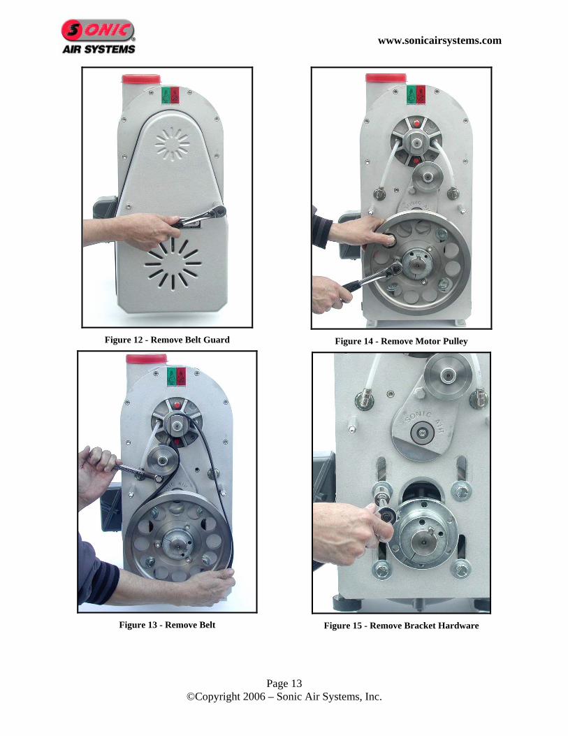
4.4.2 Blower Head Adjustment Procedure 1. Remove the belt guard using the 1/2 inch socket. (See Figure 12) 2. Disconnect the water-cooling lines at the quick disconnect on the blower head. (If
Applicable) 3. Using the 9/16 inch box-end wrench, rotate the belt tensioner arm counter
clockwise (CCW) and remove the belt. (See Figure 13) Note: If rotating the blower bracket, follow Steps 4 thru 8. If only rotating the blower head, skip to Step 7. 4. Use the ¾ inch deep socket to hold the motor pulley in place. Using the 5/16 inch
allen socket, remove the motor pulley screws and motor pulley. (See Figure 14) 5. Using the ¾ inch deep socket, remove the four bracket bolts and washers located
behind the motor pulley. (See Figure 15) 6. Rotate the bracket to the desired position and reinstall the bracket bolts and
washers. Tighten only one bolt temporarily for belt adjustment. (See Figure 16 and Figure 17)

www.sonicairsystems.com
Page 12 ©Copyright 2006 – Sonic Air Systems, Inc.
7. Using the ¼ inch allen socket, remove the eight screws from the bracket that secure the blower head. (See Figure 18)
8. Remove the water-cooling plugs from the blower head and rotate as necessary. (See Figure 19) (If Applicable)
9. Rotate the blower head to desired rotation and reinstall the eight screws to the proper torque specifications. (See Section 7.2 - Torque Specifications) (See Figure 20)
10. Using the 5/16 allen socket and the 242 Loctite, reinstall the motor pulley. 11. Using the 9/16 inch box-end wrench, rotate the belt tensioner arm counter
clockwise (CCW). At the same time wrap the belt around the blower pulley, then along the right side of the idler pulley, and finally around the motor pulley. (See Figure 21)
12. Slowly rotate the motor pulley to make sure the belt is seated in the grooves. 13. Verify that the belt gap is approximately ¾ inch ±1/16 inch. If a ¾ inch belt gap
was not achieved, use a ¾ inch deep socket to loosen the bracket mounting screws behind the motor pulley and slide the bracket. (See Figure 22 and Figure 23)
14. Using a ¾ deep socket, verify that the bracket bolts behind the motor pulley are secure. (See Section 7.2 - Torque Specifications)
15. Reinstall the water-cooling lines. (If Applicable) 16. Using the 1/2 inch socket, reinstall the belt guard.
www.sonicairsystems.com
Page 13 ©Copyright 2006 – Sonic Air Systems, Inc.
Figure 12 - Remove Belt Guard
Figure 13 - Remove Belt
Figure 14 - Remove Motor Pulley
Figure 15 - Remove Bracket Hardware

www.sonicairsystems.com
Page 14 ©Copyright 2006 – Sonic Air Systems, Inc.
Figure 16 - Rotate Bracket
Figure 17 - Install Bracket Hardware
Figure 18 - Remove Blower Hardware
Figure 19 - Move Water-Cooling Plugs
Figure 20 - Reinstall Blower Head
Figure 21 - Reinstall Belt
Figure 22 - Adjust Belt Gap to 3/4"
Figure 23 - Final Position

www.sonicairsystems.com
Page 15 ©Copyright 2006 – Sonic Air Systems, Inc.
4.5 Retro Kit Installation (Assemble Sonic blower to existing motor)
4.5.1 Tools Required Description Qty. Description Qty.
3/8 inch ratchet driver 1 9/16 inch box-end wrench 1 ¾ inch deep socket 1 1/2 inch socket 1 9/16 inch open-end wrench 1 ¼ inch flat head screwdriver 1 5/16 inch allen socket 1 Rubber mallet 1 Calipers 1 24 inch Straight edge 1 242 Loctite 1 7/32 inch allen wrench #3 Drive Extension 1
4.5.2 Retro Kit Installation 1. Using a 9/16 inch open-end wrench, mount the vibration isolators and uni-mounts
to the motor. (See Figure 24) 2. Mount the bracket assembly to the motor and then tighten only one screw using
the ¾ inch socket temporarily for belt gap adjustment. (See Figure 25) 3. Using a flat head screwdriver and a rubber mallet, wedge the screwdriver into the
front face of the bushing (Do not wedge in flange area) and then slide it onto the motor shaft. (See Figure 26)
4. Set the bushing to 1.266 ± .005 (32.2 mm) from the bushing flange to the bracket reference surface and remove the screwdriver. Using the 5/16 inch allen socket and 242 Loctite, install the two bushing screws. Tighten the screws to the specified torque, over tightening may damage the bushing. (See Figure 27, Figure 28, Figure 29, and Figure 30)(See Section 7.2 - Torque Specifications)
5. Tighten the bushing set screw using the 7/32 inch allen wrench. 6. Before installing the motor pulley, double check the bushing setting and then
install the pulley and the three pulley screws using 242 Loctite and the 5/16 inch allen socket. Tighten the three pulley screws to the required torque specifications. (See Figure 31)(See Section 7.2 - Torque Specifications)
7. Using the 9/16 inch box-end wrench, rotate the belt tensioner arm counter clockwise (CCW). At the same time wrap the belt around the blower pulley, then along the right side of the idler pulley, and finally around the motor pulley. (See Figure 32)
8. Slowly rotate the motor pulley to make sure the belt is seated in the grooves. 9. Using the rubber mallet, adjust the belt gap to ¾ inch ±1/16 inch. (See Figure 33) 10. Using the ¾ inch deep socket, tighten the bracket hardware. (See Section 7.2 -
Torque Specifications) 11. Using a straight edge, check the pulley alignment from the face of the motor
pulley to the face on the blower pulley. Verify that there is no gap and the alignment must be within ±1/32 inch. (See Figure 34)
12. Using the 1/2 inch socket, install the belt guard.

www.sonicairsystems.com
Page 16 ©Copyright 2006 – Sonic Air Systems, Inc.
Figure 24 - Install Uni-mounts
Figure 25 - Mount Bracket to Motor
Figure 26 - Prepare Bushing
Figure 27 - Install Bushing
Figure 28 – Install Bushing Hardware
Figure 29 - Bushing Installation
Figure 30 – Install Set Screw

www.sonicairsystems.com
Page 17 ©Copyright 2006 – Sonic Air Systems, Inc.
Figure 31 - Install Motor Pulley
Figure 32 - Install Belt
Figure 33 - Set Belt Gap to ¾”
Figure 34 - Check Alignment
www.sonicairsystems.com
Page 18 ©Copyright 2006 – Sonic Air Systems, Inc.
5 Electrical Wiring, and Start-Up 5.1 Motor Wiring
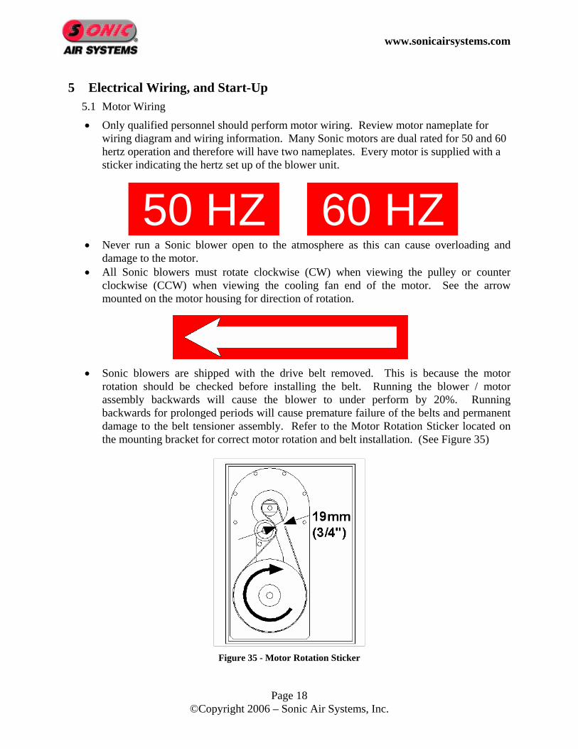
• Only qualified personnel should perform motor wiring. Review motor nameplate for wiring diagram and wiring information. Many Sonic motors are dual rated for 50 and 60 hertz operation and therefore will have two nameplates. Every motor is supplied with a sticker indicating the hertz set up of the blower unit.
• Never run a Sonic blower open to the atmosphere as this can cause overloading and damage to the motor.
• All Sonic blowers must rotate clockwise (CW) when viewing the pulley or counter clockwise (CCW) when viewing the cooling fan end of the motor. See the arrow mounted on the motor housing for direction of rotation.
• Sonic blowers are shipped with the drive belt removed. This is because the motor
rotation should be checked before installing the belt. Running the blower / motor assembly backwards will cause the blower to under perform by 20%. Running backwards for prolonged periods will cause premature failure of the belts and permanent damage to the belt tensioner assembly. Refer to the Motor Rotation Sticker located on the mounting bracket for correct motor rotation and belt installation. (See Figure 35)
Figure 35 - Motor Rotation Sticker
60 HZ 50 HZ

www.sonicairsystems.com
Page 19 ©Copyright 2006 – Sonic Air Systems, Inc.
6 Blower Specifications 6.1 Blower Specification Sheet
Description Blower – Sonic 150 Blower –Sonic 150 Water Cooled
Sonic P/N (1) 19413 (2) / 19426 (3)
19439 (2) / 19453 (3)
19455 (2) / 19464 (3) 19457 19518 (2) /
19522 (3) 19535 (2) / 19547 (3)
19550 (2) / 19561 (3) 19554
Output Flow Rate 700 cfm (331 lps) to 1,200 cfm (566 lps)
700 cfm (331 lps) to 1,200 cfm (566 lps)
Ambient Temperature 10°F (-12°C) to 105°F (40°C)
10°F (-12°C) to 105°F (40°C)
Air Temperature Range < 125°F (52°C) 125°F (52°C) to 400°F (205°C)
Motors Available 15 Hp 20 Hp 25 Hp ODP
25 Hp TEFC 15 Hp 20 Hp 25 Hp
ODP 25 Hp TEFC
Width (W) 13.0 in (330 mm)
15.63 in (397 mm)
15.63 in (397 mm)
20.75 in (528 mm)
13.0 in (330 mm)
15.63 in (397 mm)
15.63 in (397 mm)
20.75 in (528 mm)
Depth (D) 21.06 in (535 mm)
24.19 in (615 mm)
24.19 in (615 mm)
16.19 in (412 mm)
21.06 in (535 mm)
24.19 in (615 mm)
24.19 in (615 mm)
16.19 in (412 mm)
Height (H) 27.75 in (705 mm)
29.0 in (737 mm)
29.0 in (737 mm)
31.63 in (804 mm)
27.75 in (705 mm)
29.0 in (737 mm)
29.0 in (737 mm)
31.63 in (804 mm)
Mounting Pattern (A) 8.5 in (216 mm)
10.0 in (254 mm)
10.0 in (254 mm)
11.0 in (280 mm)
8.5 in (216 mm)
10.0 in (254 mm)
10.0 in (254 mm)
11.0 in (280 mm)
Approximate Weight 170.0 lbs (78.3 kg)
299 lbs (135.9 kg)
299 lbs (135.9 kg)
395 lb (180 kg)
170.0 lbs (78.3 kg)
299 lbs (135.9 kg)
299 lbs (135.9 kg)
395 lb (180 kg)
Replacement Belt P/N Pulley 1.55 to 1.90 Diameter (2) 13474 13474 13474 13451 13474 13474 13474 13451
Pulley 1.95 to 2.20 Diameter (3) 13555 13555 13555 13451 13555 13555 13555 13451 (1) P/N is dependent on pulley and belt selection – Consult Sonic Air Systems for applicable number (2) 46.0 inch Lg. belt (3) 47.0 inch Lg. belt

www.sonicairsystems.com
Page 20 ©Copyright 2006 – Sonic Air Systems, Inc.
6.2 Assembly Drawing

www.sonicairsystems.com
Page 21 ©Copyright 2006 – Sonic Air Systems, Inc.
6.3 Parts List
6.3.1 Sonic 150 Blower Unit
Item Part No. Description Qty. No. 215TC &
256TC Frame
284TSC Frame (Only)
1 Section 6.4.1 Motor, Electric 1 2 14458 Blower Head, Sonic 150 1 3 12335 12623 Bracket, Sonic 150 1 4 13455 Belt Tensioner Assembly 1 5 13450 Pulley, Blower 1 6 13452 Pulley, Motor 1 7 Section 6.4.2 Bushing Kit 1 8 Section 6.5 Belt 1 9 11130 12615 Belt Guard 1
10 11934 12548 Vibration Isolators 4 11 10653 N/A Uni-mounts 2 12 (Not Required) 13 10679 Retainer, Pulley 1 14 13506 Standoff Assembly 2 15 (Not Required) 16 10454 Screw, 5/16-18 x 1.0 Lg. SHCS SS 8 17 13482 Screw, 5/16-24 x 1.0 Lg. FHCS SS 1 18 12342 Nut, 5/16-18 Hex SS w/ Nylock 2 19 13573 Screw, 3/8-16 x 1.5 Lg. SHCS (Bushing Kit) 3 20 10759 Screw, ½-13 x 1.5 Lg. HHC Plated 4 21 12340 Screw, 5/16-18 x 1.5 Lg. FHS SS 1 22 11251 Washer, 3/8” Flat Plated 8 23 11407 Lock Washer, 3/8” Plated 8 24 10273 Nut, 3/8-16 Hex Plated 8 25 10263 Washer, ½” Plated 4 26 12364 Lock Washer, ½” Plated 4

www.sonicairsystems.com
Page 22 ©Copyright 2006 – Sonic Air Systems, Inc.
6.3.2 Sonic 150C Blower Unit
Item Part No. Description Qty. No. 215TC &
256TC Frame
284TSC Frame (Only)
1 Section 6.4.1 Motor, Electric 1 2 14459 Blower Head, Sonic 150C 1 3 12335 12623 Bracket, Sonic 150 1 4 13455 Belt Tensioner Assembly 1 5 13450 Pulley, Blower 1 6 13452 Pulley, Motor 1 7 Section 6.4.2 Bushing Kit 1 8 Section 6.5 Belt 1 9 11130 12615 Belt Guard 1
10 11934 12548 Vibration Isolators 4 11 10653 N/A Uni-mounts 2 12 Feed thru Assembly – Water Cooled 2 13 10679 Retainer, Pulley 1 14 13506 Standoff Assembly 2 15 (Not Required) 16 10454 Screw, 5/16-18 x 1.0 Lg. SHCS SS 8 17 13482 Screw, 5/16-24 x 1.0 Lg. FHCS SS 1 18 12342 Nut, 5/16-18 Hex SS w/ Nylock 2 19 13573 Screw, 3/8-16 x 1.5 Lg. SHCS (See Bushing Kit) 3 20 10759 Screw, ½-13 x 1.5 Lg. HHC Plated 4 21 12340 Screw, 5/16-18 x 1.5 Lg. FHS SS 1 22 11251 Washer, 3/8” Flat Plated 8 23 11407 Lock Washer, 3/8” Plated 8 24 10273 Nut, 3/8-16 Hex Plated 8 25 10263 Washer, ½” Plated 4 26 12364 Lock Washer, ½” Plated 4

www.sonicairsystems.com
Page 23 ©Copyright 2006 – Sonic Air Systems, Inc.
6.3.3 Sonic 150 Retro Kit Item Part No. Description Qty. No. 215TC &
256TC Frame
284TSC Frame (Only)
1 (Not Supplied) 2 14458 Blower Head, Sonic 150 1 3 12335 12623 Bracket, Sonic 150 1 4 13455 Belt Tensioner Assembly 1 5 13450 Pulley, Blower 1 6 13452 Pulley, Motor 1 7 Section 6.4.2 Bushing Kit 1 8 Section 6.5 Belt 1 9 11130 12615 Belt Guard 1
10 11934 12548 Vibration Isolators 4 11 10653 N/A Uni-mounts 2 12 (Not Required) 13 10679 Retainer, Pulley 1 14 13506 Standoff Assembly 2 15 (Not Required) 16 10454 Screw, 5/16-18 x 1.0 Lg. SHCS SS 8 17 13482 Screw, 5/16-24 x 1.0 Lg. FHCS SS 1 18 12342 Nut, 5/16-18 Hex SS w/ Nylock 2 19 13573 Screw, 3/8-16 x 1.5 Lg. SHCS (See Bushing Kit) 3 20 10759 Screw, ½-13 x 1.5 Lg. HHC Plated 4 21 12340 Screw, 5/16-18 x 1.5 Lg. FHS SS 1 22 11251 Washer, 3/8” Flat Plated 8 23 11407 Lock Washer, 3/8” Plated 8 24 10273 Nut, 3/8-16 Hex Plated 8 25 10263 Washer, ½” Plated 4 26 12364 Lock Washer, ½” Plated 4

www.sonicairsystems.com
Page 24 ©Copyright 2006 – Sonic Air Systems, Inc.
6.3.4 Sonic 150C Retro Kit Item Part No. Description Qty. No. 215TC &
256TC Frame
284TSC Frame (Only)
1 (Not Supplied) 2 14459 Blower Head, Sonic 150C 1 3 12335 12623 Bracket, Sonic 150 1 4 13455 Belt Tensioner Assembly 1 5 13450 Pulley, Blower 1 6 13452 Pulley, Motor 1 7 Section 6.4.2 Bushing Kit 1 8 Section 6.5 Belt 1 9 11130 12615 Belt Guard 1
10 11934 12548 Vibration Isolators 4 11 10653 N/A Uni-mounts 2 12 Feed thru Assembly – Water Cooled 2 13 10679 Retainer, Pulley 1 14 13506 Standoff Assembly 2 15 (Not Required) 16 10454 Screw, 5/16-18 x 1.0 Lg. SHCS SS 8 17 13482 Screw, 5/16-24 x 1.0 Lg. FHCS SS 1 18 12342 Nut, 5/16-18 Hex SS w/ Nylock 2 19 13573 Screw, 3/8-16 x 1.5 Lg. SHCS (See Bushing Kit) 3 20 10759 Screw, ½-13 x 1.5 Lg. HHC Plated 4 21 12340 Screw, 5/16-18 x 1.5 Lg. FHS SS 1 22 11251 Washer, 3/8” Flat Plated 8 23 11407 Lock Washer, 3/8” Plated 8 24 10273 Nut, 3/8-16 Hex Plated 8 25 10263 Washer, ½” Plated 4 26 12364 Lock Washer, ½” Plated 4
www.sonicairsystems.com
Page 25 ©Copyright 2006 – Sonic Air Systems, Inc.
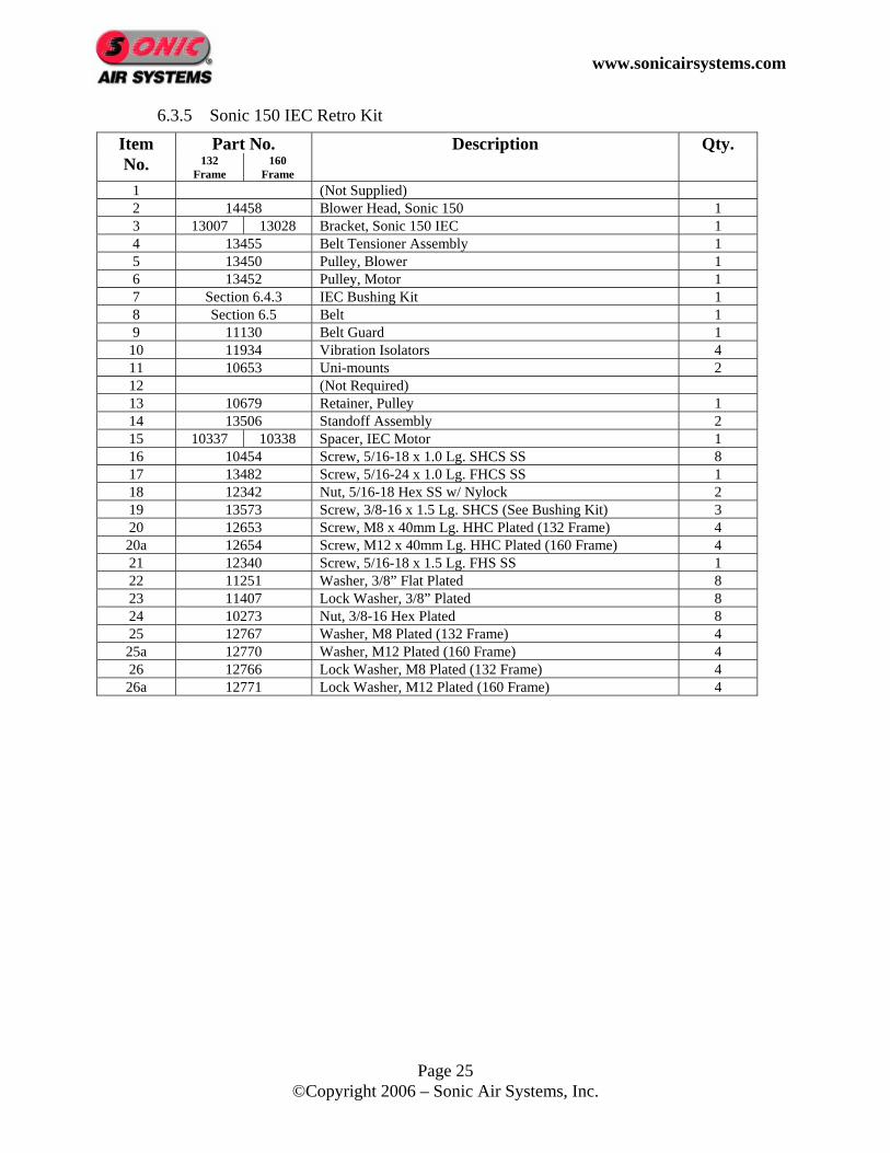
6.3.5 Sonic 150 IEC Retro Kit Item Part No. Description Qty. No. 132
Frame 160
Frame
1 (Not Supplied) 2 14458 Blower Head, Sonic 150 1 3 13007 13028 Bracket, Sonic 150 IEC 1 4 13455 Belt Tensioner Assembly 1 5 13450 Pulley, Blower 1 6 13452 Pulley, Motor 1 7 Section 6.4.3 IEC Bushing Kit 1 8 Section 6.5 Belt 1 9 11130 Belt Guard 1
10 11934 Vibration Isolators 4 11 10653 Uni-mounts 2 12 (Not Required) 13 10679 Retainer, Pulley 1 14 13506 Standoff Assembly 2 15 10337 10338 Spacer, IEC Motor 1 16 10454 Screw, 5/16-18 x 1.0 Lg. SHCS SS 8 17 13482 Screw, 5/16-24 x 1.0 Lg. FHCS SS 1 18 12342 Nut, 5/16-18 Hex SS w/ Nylock 2 19 13573 Screw, 3/8-16 x 1.5 Lg. SHCS (See Bushing Kit) 3 20 12653 Screw, M8 x 40mm Lg. HHC Plated (132 Frame) 4 20a 12654 Screw, M12 x 40mm Lg. HHC Plated (160 Frame) 4 21 12340 Screw, 5/16-18 x 1.5 Lg. FHS SS 1 22 11251 Washer, 3/8” Flat Plated 8 23 11407 Lock Washer, 3/8” Plated 8 24 10273 Nut, 3/8-16 Hex Plated 8 25 12767 Washer, M8 Plated (132 Frame) 4 25a 12770 Washer, M12 Plated (160 Frame) 4 26 12766 Lock Washer, M8 Plated (132 Frame) 4 26a 12771 Lock Washer, M12 Plated (160 Frame) 4
www.sonicairsystems.com
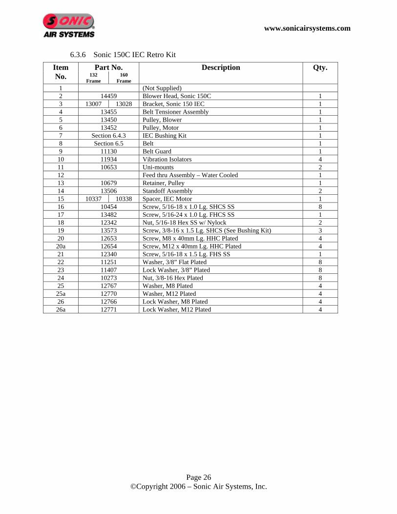
Page 26 ©Copyright 2006 – Sonic Air Systems, Inc.
6.3.6 Sonic 150C IEC Retro Kit Item Part No. Description Qty. No. 132
Frame 160
Frame
1 (Not Supplied) 2 14459 Blower Head, Sonic 150C 1 3 13007 13028 Bracket, Sonic 150 IEC 1 4 13455 Belt Tensioner Assembly 1 5 13450 Pulley, Blower 1 6 13452 Pulley, Motor 1 7 Section 6.4.3 IEC Bushing Kit 1 8 Section 6.5 Belt 1 9 11130 Belt Guard 1
10 11934 Vibration Isolators 4 11 10653 Uni-mounts 2 12 Feed thru Assembly – Water Cooled 1 13 10679 Retainer, Pulley 1 14 13506 Standoff Assembly 2 15 10337 10338 Spacer, IEC Motor 1 16 10454 Screw, 5/16-18 x 1.0 Lg. SHCS SS 8 17 13482 Screw, 5/16-24 x 1.0 Lg. FHCS SS 1 18 12342 Nut, 5/16-18 Hex SS w/ Nylock 2 19 13573 Screw, 3/8-16 x 1.5 Lg. SHCS (See Bushing Kit) 3 20 12653 Screw, M8 x 40mm Lg. HHC Plated 4 20a 12654 Screw, M12 x 40mm Lg. HHC Plated 4 21 12340 Screw, 5/16-18 x 1.5 Lg. FHS SS 1 22 11251 Washer, 3/8” Flat Plated 8 23 11407 Lock Washer, 3/8” Plated 8 24 10273 Nut, 3/8-16 Hex Plated 8 25 12767 Washer, M8 Plated 4 25a 12770 Washer, M12 Plated 4 26 12766 Lock Washer, M8 Plated 4 26a 12771 Lock Washer, M12 Plated 4

www.sonicairsystems.com
Page 27 ©Copyright 2006 – Sonic Air Systems, Inc.
6.3.7 Sonic 150 Upgrade Kit Item Part No. Description Qty. No. 215TC &
256TC Frame
284TSC Frame (Only)
2 14458 Blower Head, Sonic 150 1 3 12335 12623 Bracket, Sonic 150 1 4 13455 Belt Tensioner Assembly 1 5 13450 Pulley, Blower 1 6 13452 Pulley, Motor 1 8 Section 6.5 Belt 1 9 N/A 12615 Belt Guard 1
13 10679 Retainer, Pulley 1 14 13506 Standoff Assembly 2 16 10454 Screw, 5/16-18 x 1.0 Lg. SHCS SS 8 17 13482 Screw, 5/16-24 x 1.0 Lg. FHCS SS 1 18 12342 Nut, 5/16-18 Hex SS w/ Nylock 2
6.3.8 Sonic 150C Upgrade Kit Item Part No. Description Qty. No. 215TC &
256TC Frame
284TSC Frame (Only)
2 14459 Blower Head, Sonic 150C 1 3 12335 12623 Bracket, Sonic 150 1 4 13455 Belt Tensioner Assembly 1 5 13450 Pulley, Blower 1 6 13452 Pulley, Motor 1 8 Section 6.5 Belt 1 9 N/A 12615 Belt Guard 1
12 Feed thru Assembly – Water Cooled 2 13 10679 Retainer, Pulley 1 14 13506 Standoff Assembly 2 16 10454 Screw, 5/16-18 x 1.0 Lg. SHCS SS 8 17 13482 Screw, 5/16-24 x 1.0 Lg. FHCS SS 1 18 12342 Nut, 5/16-18 Hex SS w/ Nylock 2
www.sonicairsystems.com
Page 28 ©Copyright 2006 – Sonic Air Systems, Inc.
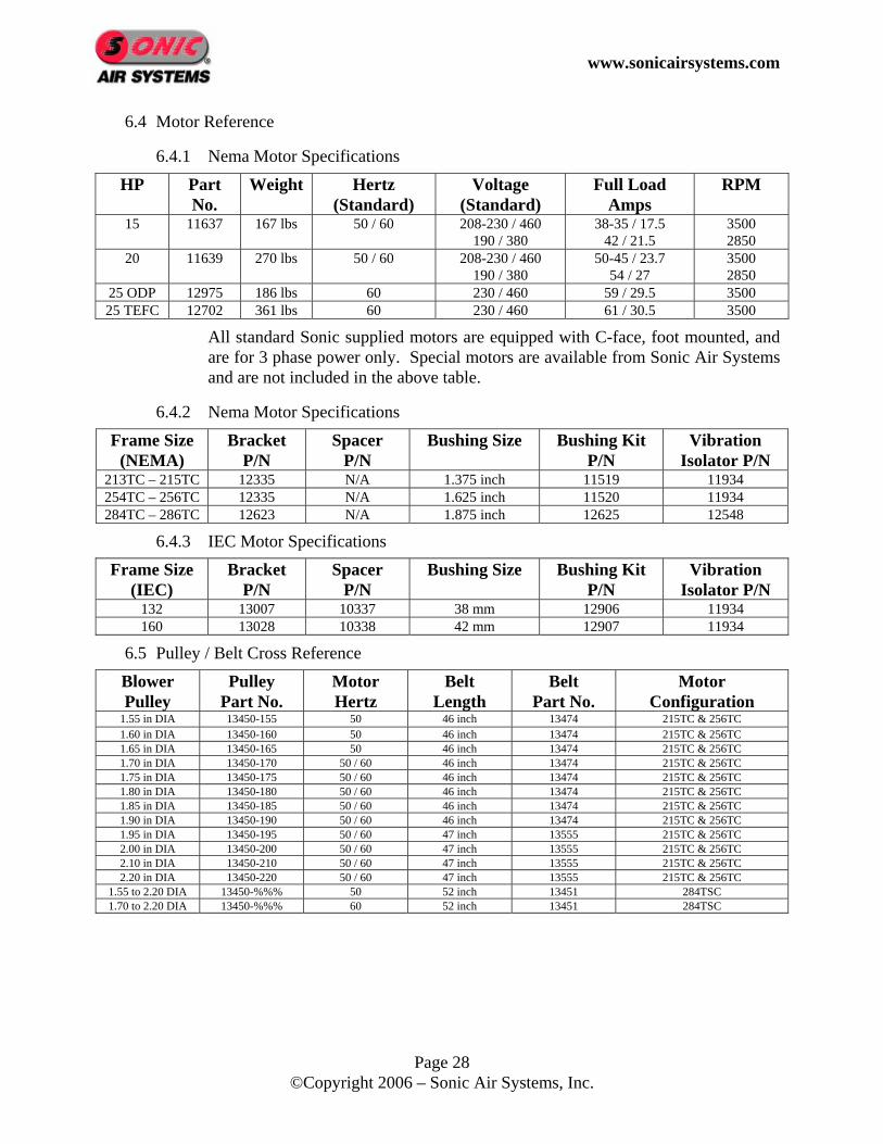
6.4 Motor Reference
6.4.1 Nema Motor Specifications HP Part
No. Weight Hertz
(Standard) Voltage
(Standard) Full Load
Amps RPM
15 11637 167 lbs 50 / 60 208-230 / 460 190 / 380
38-35 / 17.5 42 / 21.5
3500 2850
20 11639 270 lbs 50 / 60 208-230 / 460 190 / 380
50-45 / 23.7 54 / 27
3500 2850
25 ODP 12975 186 lbs 60 230 / 460 59 / 29.5 3500 25 TEFC 12702 361 lbs 60 230 / 460 61 / 30.5 3500
All standard Sonic supplied motors are equipped with C-face, foot mounted, and are for 3 phase power only. Special motors are available from Sonic Air Systems and are not included in the above table.
6.4.2 Nema Motor Specifications Frame Size
(NEMA) Bracket
P/N Spacer
P/N Bushing Size Bushing Kit
P/N Vibration
Isolator P/N 213TC – 215TC 12335 N/A 1.375 inch 11519 11934 254TC – 256TC 12335 N/A 1.625 inch 11520 11934 284TC – 286TC 12623 N/A 1.875 inch 12625 12548
6.4.3 IEC Motor Specifications Frame Size
(IEC) Bracket
P/N Spacer
P/N Bushing Size Bushing Kit
P/N Vibration
Isolator P/N 132 13007 10337 38 mm 12906 11934 160 13028 10338 42 mm 12907 11934
6.5 Pulley / Belt Cross Reference Blower Pulley
Pulley Part No.
Motor Hertz
Belt Length
Belt Part No.
Motor Configuration
1.55 in DIA 13450-155 50 46 inch 13474 215TC & 256TC 1.60 in DIA 13450-160 50 46 inch 13474 215TC & 256TC 1.65 in DIA 13450-165 50 46 inch 13474 215TC & 256TC 1.70 in DIA 13450-170 50 / 60 46 inch 13474 215TC & 256TC 1.75 in DIA 13450-175 50 / 60 46 inch 13474 215TC & 256TC 1.80 in DIA 13450-180 50 / 60 46 inch 13474 215TC & 256TC 1.85 in DIA 13450-185 50 / 60 46 inch 13474 215TC & 256TC 1.90 in DIA 13450-190 50 / 60 46 inch 13474 215TC & 256TC 1.95 in DIA 13450-195 50 / 60 47 inch 13555 215TC & 256TC 2.00 in DIA 13450-200 50 / 60 47 inch 13555 215TC & 256TC 2.10 in DIA 13450-210 50 / 60 47 inch 13555 215TC & 256TC 2.20 in DIA 13450-220 50 / 60 47 inch 13555 215TC & 256TC
1.55 to 2.20 DIA 13450-%%% 50 52 inch 13451 284TSC 1.70 to 2.20 DIA 13450-%%% 60 52 inch 13451 284TSC
www.sonicairsystems.com
Page 29 ©Copyright 2006 – Sonic Air Systems, Inc.
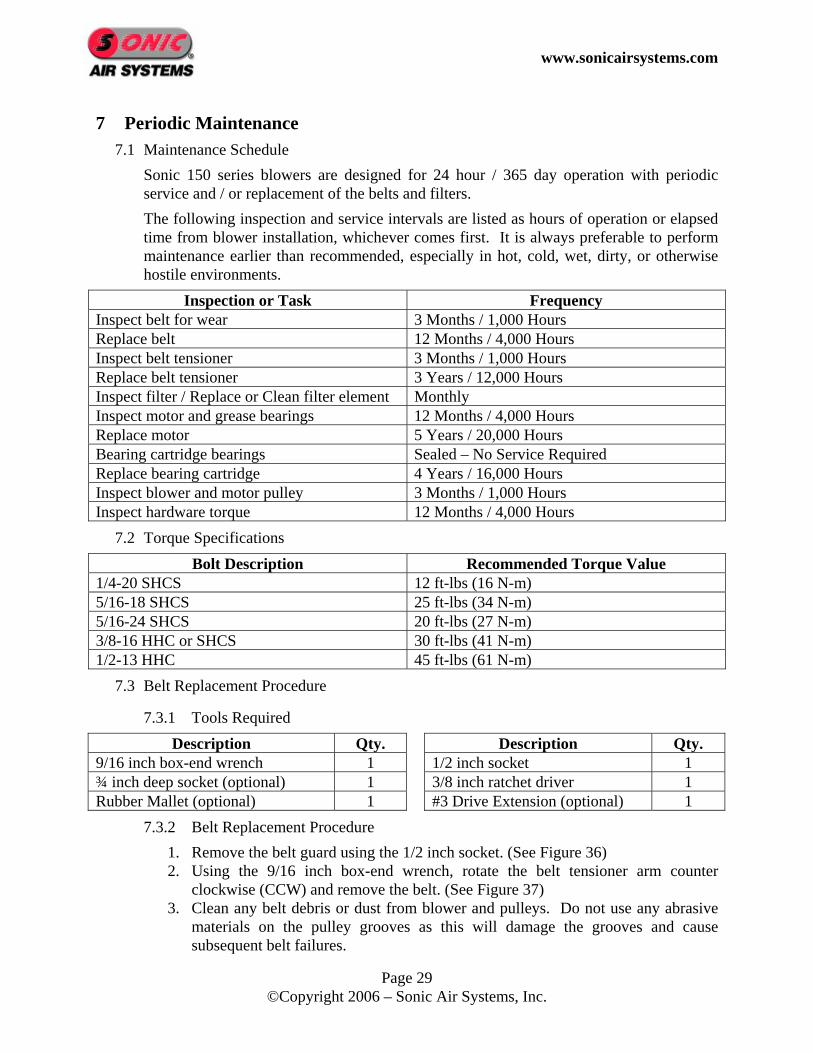
7 Periodic Maintenance 7.1 Maintenance Schedule
Sonic 150 series blowers are designed for 24 hour / 365 day operation with periodic service and / or replacement of the belts and filters. The following inspection and service intervals are listed as hours of operation or elapsed time from blower installation, whichever comes first. It is always preferable to perform maintenance earlier than recommended, especially in hot, cold, wet, dirty, or otherwise hostile environments.
Inspection or Task Frequency Inspect belt for wear 3 Months / 1,000 Hours Replace belt 12 Months / 4,000 Hours Inspect belt tensioner 3 Months / 1,000 Hours Replace belt tensioner 3 Years / 12,000 Hours Inspect filter / Replace or Clean filter element Monthly Inspect motor and grease bearings 12 Months / 4,000 Hours Replace motor 5 Years / 20,000 Hours Bearing cartridge bearings Sealed – No Service Required Replace bearing cartridge 4 Years / 16,000 Hours Inspect blower and motor pulley 3 Months / 1,000 Hours Inspect hardware torque 12 Months / 4,000 Hours
7.2 Torque Specifications Bolt Description Recommended Torque Value
1/4-20 SHCS 12 ft-lbs (16 N-m) 5/16-18 SHCS 25 ft-lbs (34 N-m) 5/16-24 SHCS 20 ft-lbs (27 N-m) 3/8-16 HHC or SHCS 30 ft-lbs (41 N-m) 1/2-13 HHC 45 ft-lbs (61 N-m)
7.3 Belt Replacement Procedure
7.3.1 Tools Required Description Qty. Description Qty.
9/16 inch box-end wrench 1 1/2 inch socket 1 ¾ inch deep socket (optional) 1 3/8 inch ratchet driver 1 Rubber Mallet (optional) 1 #3 Drive Extension (optional) 1
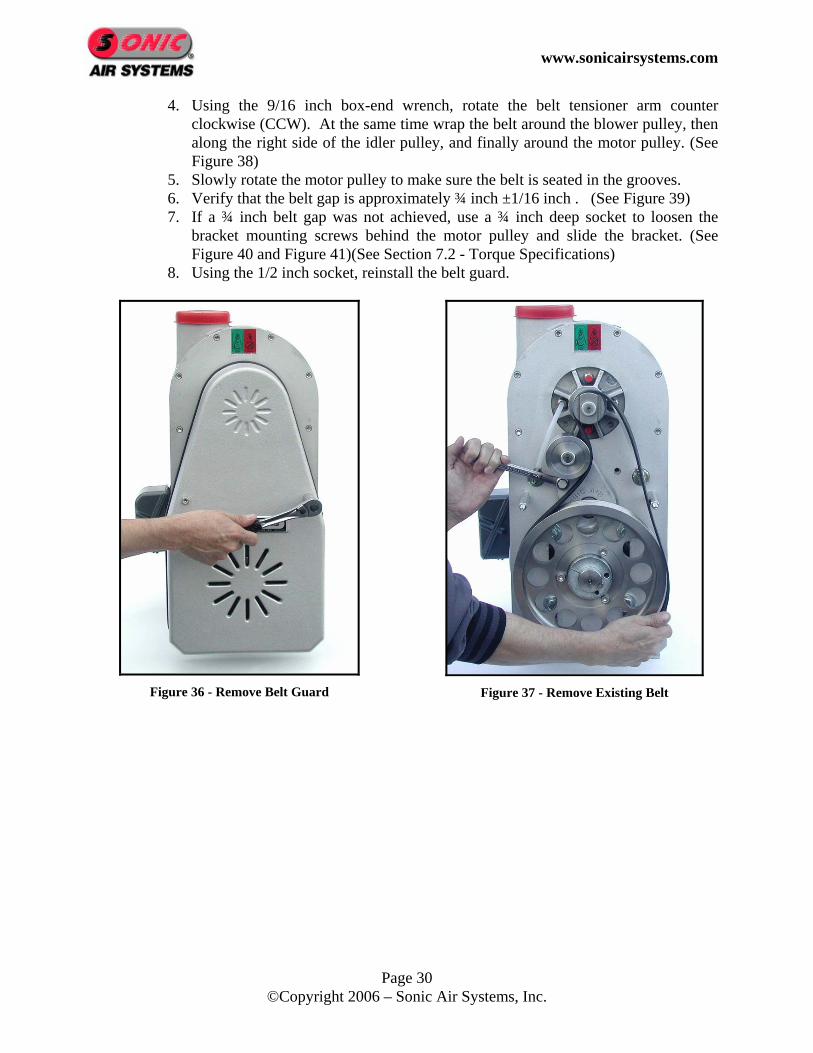
7.3.2 Belt Replacement Procedure 1. Remove the belt guard using the 1/2 inch socket. (See Figure 36) 2. Using the 9/16 inch box-end wrench, rotate the belt tensioner arm counter
clockwise (CCW) and remove the belt. (See Figure 37) 3. Clean any belt debris or dust from blower and pulleys. Do not use any abrasive
materials on the pulley grooves as this will damage the grooves and cause subsequent belt failures.
www.sonicairsystems.com
Page 30 ©Copyright 2006 – Sonic Air Systems, Inc.
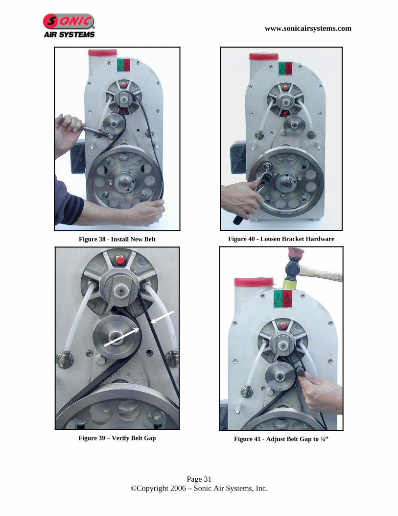
4. Using the 9/16 inch box-end wrench, rotate the belt tensioner arm counter clockwise (CCW). At the same time wrap the belt around the blower pulley, then along the right side of the idler pulley, and finally around the motor pulley. (See Figure 38)
5. Slowly rotate the motor pulley to make sure the belt is seated in the grooves. 6. Verify that the belt gap is approximately ¾ inch ±1/16 inch . (See Figure 39) 7. If a ¾ inch belt gap was not achieved, use a ¾ inch deep socket to loosen the
bracket mounting screws behind the motor pulley and slide the bracket. (See Figure 40 and Figure 41)(See Section 7.2 - Torque Specifications)
8. Using the 1/2 inch socket, reinstall the belt guard.
Figure 36 - Remove Belt Guard
Figure 37 - Remove Existing Belt
www.sonicairsystems.com
Page 31 ©Copyright 2006 – Sonic Air Systems, Inc.
Figure 38 - Install New Belt
Figure 39 – Verify Belt Gap
Figure 40 - Loosen Bracket Hardware
Figure 41 - Adjust Belt Gap to ¾”

www.sonicairsystems.com
Page 32 ©Copyright 2006 – Sonic Air Systems, Inc.
7.4 Belt Tensioner Service
7.4.1 Tools Required Description Qty. Description Qty.
3/16 inch allen wrench 1 #3 Drive Extension (optional) 1 9/16 inch box end wrench 1 ¾ inch deep socket (optional) 1 1/2 inch socket 1 Rubber Mallet (optional) 1 3/8 inch ratchet driver 1
7.4.2 Belt Tensioner Service Procedure 1. Remove the belt guard using the 1/2 inch socket. (See Figure 42) 2. Using the 9/16 inch box-end wrench, rotate the belt tensioner arm counter
clockwise (CCW) and remove the belt. (See Figure 43) 3. Use the ¾ inch deep socket to hold the motor pulley in place. Using the 5/16 inch
allen socket, remove the motor pulley screws and motor pulley. (See Figure 44) 4. Using the 3/16 inch allen wrench, secure the flat head screw from the back of the
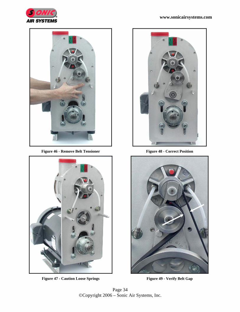
bracket while loosening the nylon-insert locknut with a ½ inch socket. This will allow the removal of the belt tensioner. (See Figure 45 and Figure 46)
5. Caution: After removing belt tensioner, the compression springs will be exposed. Remove these springs temporarily if the new belt tensioner is not installed immediately. Wear safety glasses to prevent potential eye injury. (See Figure 47)
6. At reassembly, the static position should be approximately 25 degrees to the right of blower pulley. Install a new nylon-insert locknut to 20 ft-lbs when installing the new belt tensioner. (See Figure 48)
7. Using the 9/16 inch box-end wrench, rotate the belt tensioner arm counter clockwise (CCW). At the same time wrap the belt around the blower pulley, then along the right side of the idler pulley, and finally around the motor pulley.
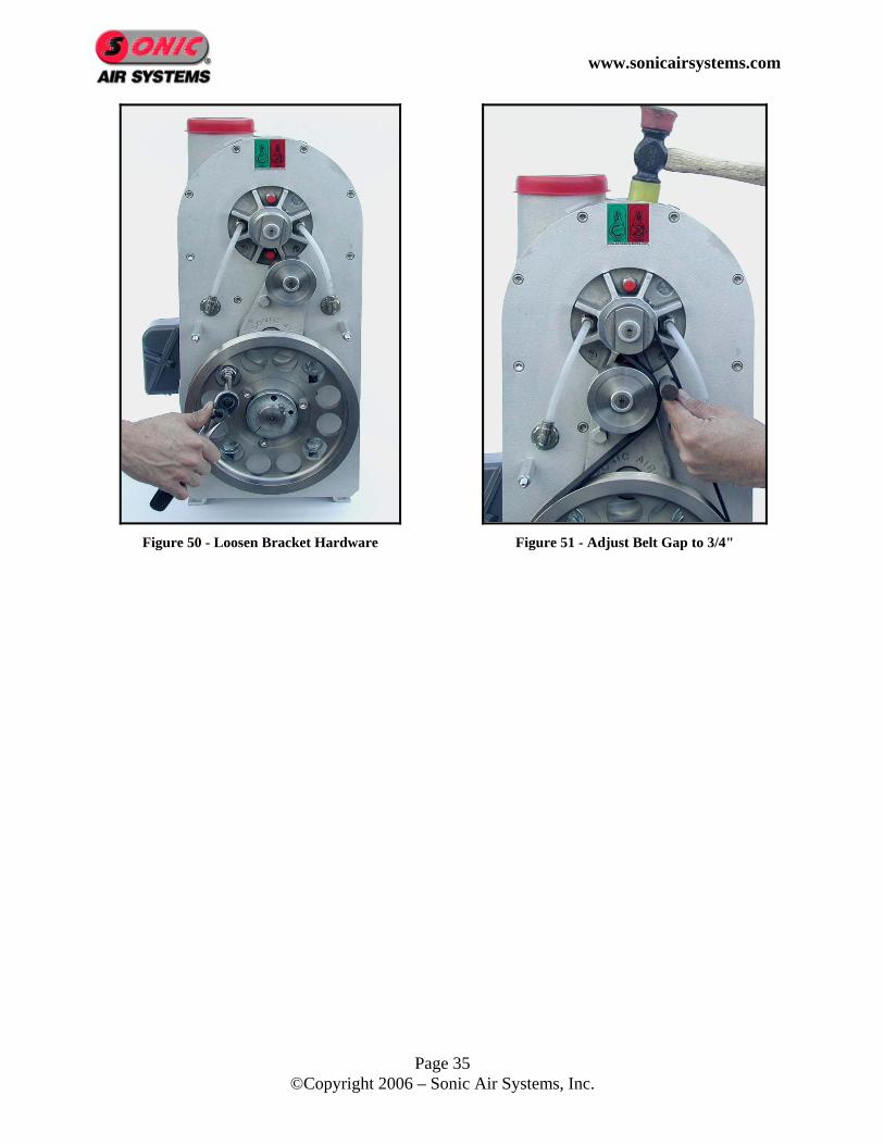
8. Slowly rotate the motor pulley to make sure the belt is seated in the grooves. 9. Verify that the belt gap is approximately ¾ inch (Factory Set). (See Figure 49) 10. If a ¾ inch belt gap was not achieved, use a ¾ inch deep socket to loosen the
bracket mounting screws behind the motor pulley and slide the bracket. (See Figure 50 and Figure 51)
11. Using the 1/2 inch socket, reinstall the belt guard.

www.sonicairsystems.com
Page 33 ©Copyright 2006 – Sonic Air Systems, Inc.
Figure 42 - Remove Belt Guard
Figure 43 - Remove Belt
Figure 44 - Remove Motor Pulley
Figure 45 - Remove Bolt
www.sonicairsystems.com
Page 34 ©Copyright 2006 – Sonic Air Systems, Inc.
Figure 46 - Remove Belt Tensioner
Figure 47 - Caution Loose Springs
Figure 48 - Correct Position
Figure 49 - Verify Belt Gap
www.sonicairsystems.com
Page 35 ©Copyright 2006 – Sonic Air Systems, Inc.
Figure 50 - Loosen Bracket Hardware
Figure 51 - Adjust Belt Gap to 3/4"

www.sonicairsystems.com
Page 36 ©Copyright 2006 – Sonic Air Systems, Inc.
7.5 Bearing Cartridge Replacement Procedure
7.5.1 Assembly Drawing
www.sonicairsystems.com
Page 37 ©Copyright 2006 – Sonic Air Systems, Inc.
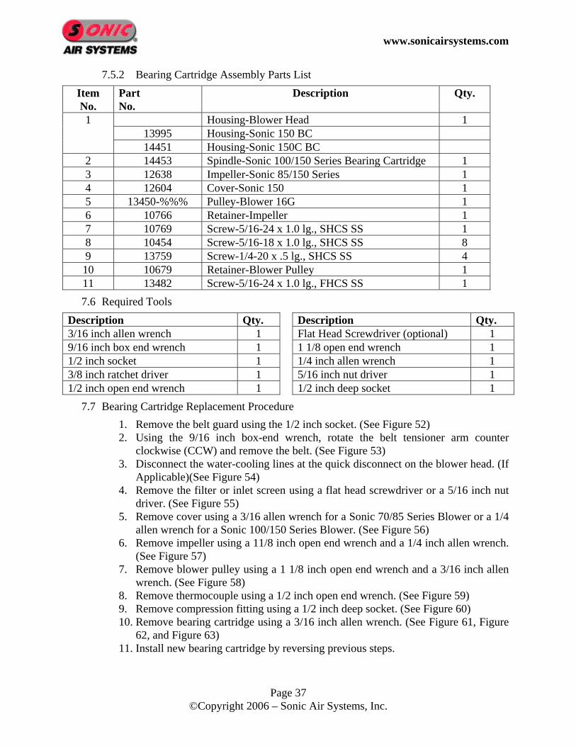
7.5.2 Bearing Cartridge Assembly Parts List Item No.
Part No.
Description Qty.
1 Housing-Blower Head 1 13995 Housing-Sonic 150 BC 14451 Housing-Sonic 150C BC 2 14453 Spindle-Sonic 100/150 Series Bearing Cartridge 1 3 12638 Impeller-Sonic 85/150 Series 1 4 12604 Cover-Sonic 150 1 5 13450-%%% Pulley-Blower 16G 1 6 10766 Retainer-Impeller 1 7 10769 Screw-5/16-24 x 1.0 lg., SHCS SS 1 8 10454 Screw-5/16-18 x 1.0 lg., SHCS SS 8 9 13759 Screw-1/4-20 x .5 lg., SHCS SS 4 10 10679 Retainer-Blower Pulley 1 11 13482 Screw-5/16-24 x 1.0 lg., FHCS SS 1 7.6 Required Tools
Description Qty. Description Qty. 3/16 inch allen wrench 1 Flat Head Screwdriver (optional) 1 9/16 inch box end wrench 1 1 1/8 open end wrench 1 1/2 inch socket 1 1/4 inch allen wrench 1 3/8 inch ratchet driver 1 5/16 inch nut driver 1 1/2 inch open end wrench 1 1/2 inch deep socket 1
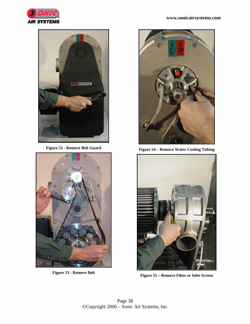
7.7 Bearing Cartridge Replacement Procedure 1. Remove the belt guard using the 1/2 inch socket. (See Figure 52) 2. Using the 9/16 inch box-end wrench, rotate the belt tensioner arm counter
clockwise (CCW) and remove the belt. (See Figure 53) 3. Disconnect the water-cooling lines at the quick disconnect on the blower head. (If
Applicable)(See Figure 54) 4. Remove the filter or inlet screen using a flat head screwdriver or a 5/16 inch nut
driver. (See Figure 55) 5. Remove cover using a 3/16 allen wrench for a Sonic 70/85 Series Blower or a 1/4
allen wrench for a Sonic 100/150 Series Blower. (See Figure 56) 6. Remove impeller using a 11/8 inch open end wrench and a 1/4 inch allen wrench.
(See Figure 57) 7. Remove blower pulley using a 1 1/8 inch open end wrench and a 3/16 inch allen
wrench. (See Figure 58) 8. Remove thermocouple using a 1/2 inch open end wrench. (See Figure 59) 9. Remove compression fitting using a 1/2 inch deep socket. (See Figure 60) 10. Remove bearing cartridge using a 3/16 inch allen wrench. (See Figure 61, Figure
62, and Figure 63) 11. Install new bearing cartridge by reversing previous steps.
www.sonicairsystems.com
Page 38 ©Copyright 2006 – Sonic Air Systems, Inc.
Figure 52 - Remove Belt Guard
Figure 53 - Remove Belt
Figure 54 – Remove Water Cooling Tubing
Figure 55 – Remove Filter or Inlet Screen

www.sonicairsystems.com
Page 39 ©Copyright 2006 – Sonic Air Systems, Inc.
Figure 56 – Remove Cover
Figure 57 – Remove Impeller
Figure 58 – Remove Blower Pulley
Figure 59 – Remove Thermocouple

www.sonicairsystems.com
Page 40 ©Copyright 2006 – Sonic Air Systems, Inc.
Figure 60 – Remove Compression Fitting
Figure 61 – Remove Bearing Cartridge Hardware
Figure 62 – Remove Bearing Cartridge
Figure 63 – Blower w/ Bearing Cartridge
Removed

www.sonicairsystems.com
Page 41 ©Copyright 2006 – Sonic Air Systems, Inc.
7.8 Recommended Spares Although the Sonic 150 blowers are designed for many years of continued operation, a number of components are wear or consumable items and must be replaced periodically. The following is a list of recommended spare components that should be used to minimize equipment or line down time:
Part No.
Description Recommended Qty.
14453 Spindle - Sonic 100/150 Series 1 13450-%%% Pulley, Blower (16 Groove)
(%%% Pulley Diameter, 1.55 to 2.20) 1
13452 Pulley, Motor (16 Groove) 1 13474 Belt, 46” Lg., 16 Groove
(1.55 to 1.90 Blower Pulley) 2
13555 Belt, 47” Lg. 16 Groove (1.95 to 2.20 Blower Pulley)
2
13451 Belt, 52” Lg., 16 Groove (1.55 to 2.20 Blower Pulley)(25hp Only)
2
13455 Belt Tensioner Replacement Kit 1 10316 Filter Element, Paper 2 10317 Filter Element, Polyester 1
See Section 6.4 Motor 1
www.sonicairsystems.com
Page 42 ©Copyright 2006 – Sonic Air Systems, Inc.
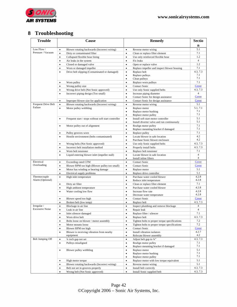
8 Troubleshooting Trouble Cause Remedy Sectio
n • Blower rotating backwards (Incorrect wiring) • Reverse motor wiring 5.1 • Dirty or contaminated filter • Clean or replace filter element 7.1 • Collapsed flexible hose lining • Use only reinforced flexible hose 1.2 • Air leaks in the system • Fix leaks 4 • Closed or damaged valve • Open or replace valve 1.2 • Worn or damaged impeller • Replace impeller and inspect blower housing 7.1 • Drive belt slipping (Contaminated or damaged) • Replace belt
• Replace pulleys • Clean pulleys
4.3, 7.3 7.1 7.1
• Worn pulley • Replace worn pulleys 7.1 • Wrong pulley size • Contact Sonic Cover • Wrong drive belt (Not Sonic approved) • Use only Sonic supplied belts 4.3, 7.3 • Incorrect piping design (Too small) • Increase piping diameter
• Contact Sonic for design assistance 4
Cover
Low Flow / Pressure / Vacuum
• Improper blower size for application • Contact Sonic for design assistance Cover • Blower rotating backwards (Incorrect wiring) • Reverse motor wiring 5.1 • Motor pulley wobbling • Replace motor
• Replace motor bushing • Replace motor pulley
5.1, 7.1 7.1 7.1
• Frequent start / stops without soft start controller • Install soft start motor controller • Install diverter valve and run continuously
5.1 5.1
• Motor pulley out of alignment • Realign motor pulley • Replace mounting bracket if damaged
7.1 7.1
• Pulley grooves worn • Replace pulley 7.1 • Hostile environment (belts contaminated) • Locate blower in safe location
• Purchase Sonic blower enclosure 4.2 4.2
• Wrong belts (Not Sonic approved) • Use only Sonic supplied belts 4.3, 7.3 • Incorrect belt installation method • Properly install belts 4.3, 7.3 • Worn belt tensioner • Replace belt tensioner 7.1
Frequent Drive Belt Failure
• Liquid entering blower inlet (impeller stall) • Locate blower in safe location • Install inline filters
4 4
• Exceeding rated CFM • Contact Sonic Cover • Blower RPM too high (Blower pulley too small) • Contact Sonic Cover • Motor has winding or bearing damage • Replace motor 5.1
Electrical Overloading
• Electrical supply problems • Replace drive controller 5.1 • High inlet temperature • Purchase water cooled blower
• Reduce inlet temperature 4.2.8 4.2.8
• Dirty air filter • Clean or replace filter element 7.1 • High ambient temperature • Purchase water cooled blower 4.2.8 • Water cooling low flow • Increase flow rate
• Decrease water temperature 4.2.8 4.2.8
• Blower speed too high • Contact Sonic Cover
Thermocouple Alarm (Optional)
• Broken belt (low temp) • Replace belt 4.3, 7.3 • Blockage in air line • Inspect plumbing and remove blockage 4 • Leak in air line • Repair leak 4 • Inlet silencer damaged • Replace filter / silencer 7.1 • Worn drive belt • Replace belt 4.3, 7.3 • Bolts loose on blower / motor assembly • Tighten bolts to proper torque specifications 7.2 • Motor mounts loose • Tighten bolts to proper torque specifications 7.2 • Blower RPM too high • Contact Sonic Cover
Irregular / Excessive Noise
• Blower is receiving vibration from nearby equipment
• Install vibration isolators • Relocate blower assembly
4.2.7 4.2
• ¾ inch gap not set • Adjust belt gap to ¾” 4.3, 7.3 • Pulleys misaligned • Realign motor pulley
• Replace mounting bracket if damaged 7.1 7.1
• Blower pulley wobbling • Replace motor • Replace motor bushing • Replace motor pulley
5.1 7.1 7.1
• High motor torque • Replace motor with low torque equivalent 5.1 • Blower rotating backwards (Incorrect wiring) • Reverse motor wiring 5.1 • Belt not set in grooves properly • Install belt correctly 4.3, 7.3
Belt Jumping Off
• Wrong belt (Not Sonic approved) • Install Sonic supplied belt 4.3, 7.3
www.sonicairsystems.com
Page 43 ©Copyright 2006 – Sonic Air Systems, Inc.
9 Performance Guarantee
Sonic Air Systems, Inc. (SAS) guarantees that each SAS supplied system will meet or exceed the designed level of performance. In the event the system does not achieve the designed performance, SAS will provide additional resources and equipment at no cost or refund 100% of the original purchase price.
SAS must have quoted the system and supplied the system as quoted Buyer pays the original invoice within terms Buyer submits notification of system deficiency within 45 days of the original invoice date and allows
SAS to remedy the deficiency Buyer must obtain written return authorization from SAS for any returns Buyer will return the system complete and in like new condition
www.sonicairsystems.com
Page 44 ©Copyright 2006 – Sonic Air Systems, Inc.
10 Warranty Policy Sonic Air Systems, Inc. (SAS) and its employees are proud of our products and are committed to providing our customers with quality, engineered products. Scope of Warranty: All SAS designed products are warranted against defects in SAS design, workmanship and materials.
Warranty Period: Blower motor units are warranted for 18 months commencing on the invoice date from SAS Retro-kits and blower heads are warranted for 12 months commencing on the invoice date from SAS Repaired blower heads are warranted for 6 months commencing on the invoice date from SAS Accessories are warranted for 24 months commencing on the invoice date from SAS
Repairs Within the Scope of the Warranty: If a SAS designed product is defective and the defect occurs during the warranty period, SAS will either repair or replace, whichever SAS believes to be appropriate under the circumstances. SAS is not responsible for removal or reinstallation of product or any incidental or consequential damages resulting from the defect, removal, reinstallation, shipment, or otherwise. Repairs Outside the Scope of the Warranty: Problems with SAS products can be due to faulty installation, misapplication, inadequate maintenance, non-SAS additions or modifications, or other problems not due to defects in SAS design, workmanship or materials. If SAS determines the warranty consideration is not due to defects in SAS design, workmanship or materials, the buyer will be responsible for the cost of any necessary repairs. Procedure to Receive Warranty Service:
Buyer obtains a written return authorization number from SAS The authorization number must be noted on the outside of the shipping container Buyer will ship F.O.B. destination freight prepaid to SAS factory Non-compliance to any of the above procedures, damage resulting from improper packaging, or product
exposed to a hazardous substance may result in SAS refusing shipment International buyer, please contact SAS for the nearest authorized warranty center
Warranty exclusions: Motors shall be warranted under the respective manufacturer’s policy Product with a tampered warranty seal Damage from fire, flood, theft, or vandalism Applications not approved by SAS which includes but not limited to product exposed to toxic, flammable,
corrosive or other hazardous substance Damage resulting from installation or operational error Damage resulting from transportation carrier Belts, filter elements, or other similar service items Blower heads not repaired by factory authorized personnel
No Other Warranties and Liability Limitation: THIS WARRANTY IS EXCLUSIVE AND IS IN LIEU OF ALL OTHER WARRANTIES WHETHER WRITTEN, ORAL OR IMPLIED. SAS’ LIABILITY IN ALL CASES WILL BE LIMITED TO THE REPLACEMENT PRICE OF ITS PRODUCT. AT NO TIME SHALL SAS BE LIABLE FOR ANY COSTS TO THE BUYER FOR LABOR, TRANSPORTATION OR DOWNTIME RESULTING FROM EQUIPMENT FAILURES BY SAS OR OUR SUPPLIERS.
www.sonicairsystems.com
Page 45 ©Copyright 2006 – Sonic Air Systems, Inc.
11 24/7/365 Service Program
Sonic Air Systems, Inc. (SAS) provides emergency product and shipping service, 24 hours a day, 7 days a week, 365 days a year, to all customers, worldwide. Shipments are made by Federal Express, UPS or UPS' Sonic Air Service or product may be picked up will-call at the SAS facility in Brea, CA USA. Simply call us at (714) 473-3694 for your immediate service needs.
SAS charges Sonic list price to the buyer Distributor discounts and commissions are ineligible on this program All costs will be charged to the buyer’s credit card (Master Card, Visa, or American Express, only) or to
their previously established SAS credit line that is currently in good standing Payments made in US dollars only The cost for UPS’ SonicAir Service is approximately $500.00 for a 25 pound package for next flight
delivery within the USA International shipments will take additional time due to import regulations within the country of destination UPS’ SonicAir Service will attempt to have the product(s) clear international customs and import
procedures, however, UPS cannot guarantee governmental acceptance SAS return authorization procedures and policies apply

www.sonicairsystems.com
Page 46 ©Copyright 2006 – Sonic Air Systems, Inc.
12 Sonic Repair Policy Sonic blower heads are high-speed close tolerance machined components. The Sonic 150 blower head is rated for a 20,000 RPM maximum impeller speed. Sonic uses only the best internal components for the blower head assembly and is confident that the head will perform exceptionally in the application it was designed to perform. As with all moving components, the blower head is subject to wear and eventually will fail. Periodic maintenance and inspections will ensure the longest possible life expectancy for the blower head. The most typical mode of failure will be from the shaft bearings and with periodic inspections; this failure can be predicted to some extent. Sonic can also provide a thermocouple option to monitor the temperature of the bearing housing which is used to predict an imminent bearing failure. Due to the complexity of the internal assembly, the precision components, and the experience of Sonic assembly and repair technicians; it is not recommended that the unit be serviced or repaired in the field. Any attempt to repair the unit within the warranty period will void the warranty. Sonic does offer a repair program in the event the blower fails outside of the warranty period and the blower head is not severely worn or damaged. Sonic recommends that in the event that a blower failure will cause interrupted production, a replacement blower head be purchased as a spare item. Follow the below return authorization procedure when requesting a blower head repair: Sonic Air Systems, Inc. (SAS) recognizes the need to return product in certain circumstances. SAS requests written return authorization to track incoming shipments and to efficiently process any repairs or credit invoices.
Repair Return Authorization Procedure Buyer issues a purchase order requesting and authorizing a blower head repair (reference purchase order
requirements) A repair order number will be communicated by 4:30pm PST The blower head must include the blower pulley The repair order number must be noted on the outside of the shipping container Buyer will ship F.O.B. destination freight prepaid to SAS factory Non-compliance to any of the above procedures, damage resulting from improper packaging, or product
exposed to a hazardous substance may result in SAS refusing shipment Repairs will be shipped within 24 hours of receipt in the USA and within 48 hours of receipt
internationally