Embed Size (px)
Citation preview

Olympus FV1000 User guide December 8, 2009 Olympus FV1000 MPE Microscope User Guide
A. System Start Up 1. Sign in to the log book. Indicate the laser lines you will
use; visible laser and IR laser.
2. Turn on mercury lamp power supply b.
3. Turn on microscope controller and scanner.
Microscope controller‐ switch ON c
Scanner – switch ON and turn Key to ON d.
4. Turn on laser combiners ef.
5. Turn on laser power supplies
Multi‐Ar g: Switch to ON and turn Key to ON.
HeNe h: Turn Key to ON.
6. Turn on computer i.
7. Enter user name/password to log on to Windows XP.
8. Start the FV10‐ASW program and enter User ID
and password.
bc
d
e
f
h
g
i

Olympus FV1000 User guide December 8, 2009 B. Outline of Acquisition setting/ Image Acquisition/ Image Viewer Windows
Acquisition setting window
Image Acquisition Window
Scan mode
Scan speed (the
slower, the better
image)
Image size
(number of pixel)
Zoom and Rotation
Lambda scanning setting
Time Interval & number
setting for time‐series
Transmitted observation
(visual)
Fluorescent
observation
(visual)
Kalman frame
averaging
Spectral
window
setting
Light Path
setting
Dye List setting
Sequential
scanning mode
Transmitted
light (halogen
lamp) control
Confocal
aperture control
Scan buttons Imaging mode
selection
(xy/xyz/xyt)
Laser power level controller
Image detection
channel setting
Microscope control: objective
selection/ focus/setting z‐
series

Olympus FV1000 User guide December 8, 2009 Image view window
C. Viewing with Transmitted/Fluorescent Light
Before scanning the sample with laser light, you may
want to look at the sample and find the region of
interest first with transmitted or fluorescent light.
Click on transmitted light button j for transmitted
light observation or on fluorescent light button 1) for
fluorescent observation.
Turn the filter wheel 1! to #5 (empty) for transmitted
light, or #3 (green) or 4 (red) for fluorescent light.
Make sure to open the shutter 1@.
Make sure the slide and coverglass are clean and
sealed. Place the slide on the microscope stage.
Focus onto the sample with the focus knob 1# (fine
adjustment) or focus buttons 1$ (coarse focusing).
Adjust the transmitted light level with the lamp switch
1% and level buttons 1^ or click on lamp controller 1& on the image acquisition control window.
When you are ready for laser scanning, turn the filter
wheel 1! to #1.
Folder/File
Explorer
Data manager: displays
metadata containing
acquisition parameters.
j
1)1!
1@
1#
1$
1%
1^
1&
Olympus FV1000 User guide December 8, 2009
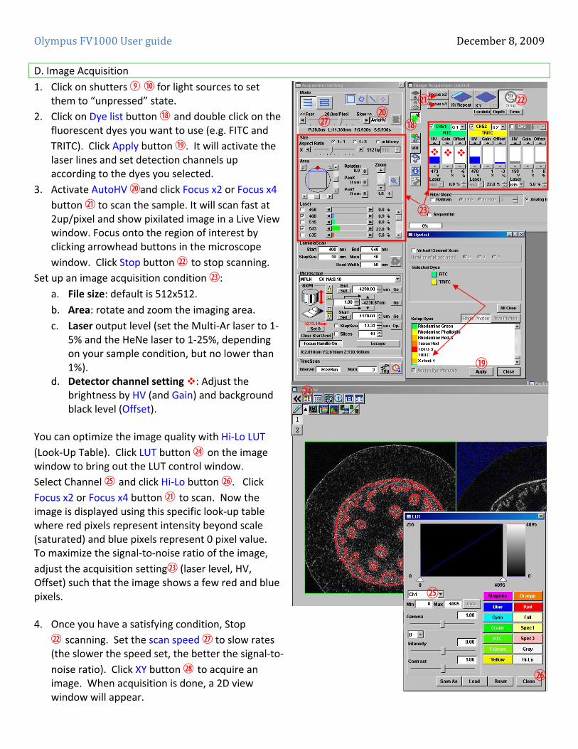
D. Image Acquisition
1. Click on shutters j 1) for light sources to set them to “unpressed” state.
2. Click on Dye list button 1* and double click on the fluorescent dyes you want to use (e.g. FITC and
TRITC). Click Apply button 1(. It will activate the laser lines and set detection channels up according to the dyes you selected.
3. Activate AutoHV 2)and click Focus x2 or Focus x4
button 2! to scan the sample. It will scan fast at 2up/pixel and show pixilated image in a Live View window. Focus onto the region of interest by clicking arrowhead buttons in the microscope
window. Click Stop button 2@ to stop scanning. Set up an image acquisition condition 2#:
a. File size: default is 512x512.
b. Area: rotate and zoom the imaging area.
c. Laser output level (set the Multi‐Ar laser to 1‐5% and the HeNe laser to 1‐25%, depending on your sample condition, but no lower than 1%).
d. Detector channel setting : Adjust the brightness by HV (and Gain) and background black level (Offset).
You can optimize the image quality with Hi‐Lo LUT
(Look‐Up Table). Click LUT button 2$ on the image window to bring out the LUT control window.
Select Channel 2% and click Hi‐Lo button 2^. Click
Focus x2 or Focus x4 button 2! to scan. Now the image is displayed using this specific look‐up table where red pixels represent intensity beyond scale (saturated) and blue pixels represent 0 pixel value. To maximize the signal‐to‐noise ratio of the image,
adjust the acquisition setting2# (laser level, HV, Offset) such that the image shows a few red and blue pixels. 4. Once you have a satisfying condition, Stop
2@ scanning. Set the scan speed 2& to slow rates (the slower the speed set, the better the signal‐to‐
noise ratio). Click XY button 2* to acquire an image. When acquisition is done, a 2D view window will appear.
2#
1*
1(
2)2! 2@
2$
2&
2^
2%

Olympus FV1000 User guide December 8, 2009
E. Z‐series Image Acquisition
Use this mode to obtain optical section through the depth (z dimension) of your sample that can be used for 3D visualization. The upper and lower limit of z‐series will be determined.
Click Focus x2 or Focus x4 button 2! to scan. Use the
Upper arrowheads and lower arrowheads buttons 2( to focus into different Z‐axial planes (large arrowhead buttons shift a full step size and small ones a half step size). When you find upper limit of your sample, click
End Set 3) button. Bring the focus down until you
find lower limit and click Start Set 3! button.
Determine the Step Size and the number of Slices 3@, which correlate with each other. It is recommended to set the step size similar to the optical section thickness of the objective you are using, so that there is no gap between the optical sections upon projection into 3D.
Click Stop button. Adjust the Scan Speed 3#, click
Depth 3$ button (“Z” will be appear on the XY button
to become XYZ), and then click XYZ 3% button.
When acquisition is done, Append Next/SeriesDone
3^ button will appear over the Stop button. Click Append Next button to add additional sections at next
step (enter the number 3& of series you want to add) or click SeriesDone to finish the acquisition. Save the image.
E. Sequential Scanning mode
Use sequential scanning to prevent possible cross‐talk and/or bleed‐through between the emissions of the fluorophores you used.
Check the Sequential box 3* and it will bring up the sequential scan information window. Choose
between line sequential or frame sequential mode3(.
Click Focus x2 or Focus x4 button4! to scan and adjust the acquisition setting to desired condition. Stop scanning. Select Scan speed at a slower rate
and click XY 4@ button to acquire an image.
2!
2( 3)3!
3@
3# 3$
3%
3^3%
3&
3*3(
4) 4@

Olympus FV1000 User guide December 8, 2009 F. Saving Images
1. Click on the image view window to be saved.
2. Click on diskette b icon or select File/Save from menu.
3. Save as window will appear. In case the image should be saved
in Image folder of Log‐in user, click on My Image Folder c
button and it will direct to your image folder. Select *.oibdfile type and click on Save button.
4. To set up your image folder where you can jump by clicking My
Image Folder button, select Tools/Option menu. Click
Generale tab and specify the path of your image folder with
Browsef button. [Upon creating a user account, each user will have its own folder in D drive (Do not create any folder in C drive.). Click OK button.
5. Oib file type contains all the metadata including all the acquisiotn parameters and it can be opened in FV10‐ASW program. The light version of this program is available for installing in user’s own computer. Otherwise, the image file can be exported as other file format so that it can be opened and manipulated in other imaging software.
To export images:
1. Select File/Export or File/Export Multi‐Tiff menu. Click My Image Folder button if the current folder is not yours.
2. For Export Multi‐Tiff option, it saves the image as a single tiff file that can contain multiple frames, like z‐ or t‐ series. This file type can be opened in Image J software.
b
c
d
f
e

Olympus FV1000 User guide December 8, 2009 3. Export command brings a window with different
options.
Section g : selecting file type for export.
Section h: setting section to save the file with ROI.
Section i: Output format selection. 1) RGB Color: the red, green, and blue channel will be saved in color as individual *.tif files in a folder. 2) RGB Color + Gray Scale box checked: the color channels will be saved in gray scale as *.tif files in a folder. 3) Merge Channel: a single merged color image will be saved as a *.tif file.
Section j: setting parameters for movies. 4. Click Save button. 5. Transfer your image data to CD or USB flash memory.
ji
g
h

Olympus FV1000 User guide December 8, 2009 G. System Shut‐Down Procedure Wipe off the oil from any oil objectives you have used
during your session.
Logging off and transferring data.
1. Exit the FV10‐ASW program. 2. Make sure that you transfer your image file to
CD or USB flash memory. All image files more than a month old will be removed during monthly clean‐up.
3. Log off Windows XP. If someone signs up for use within a next 1 hour or so, leave the system ON. If not, shut down the system as follows.
Shutting Off the system.
1. Shut down the computer B.
2. Turn the mercury lamp off C. 3. Turn the microscope controller key to OFF and turn
off both scanner and controller I/O switches d.
4. Turn off the laser combiners e, FV10‐MCPSU and FV10‐MP‐LCU.
5. Turning off the Multi‐Ar laser f by turning the key switch to OFF first and then turn the I/O power switch to OFF.
6. Turn the key of HeNe laser g to OFF.
c
b
df
g
e
Olympus FV1000 multiphoton mode December 8, 2009 Olympus FV1000 Multiphoton Imaging
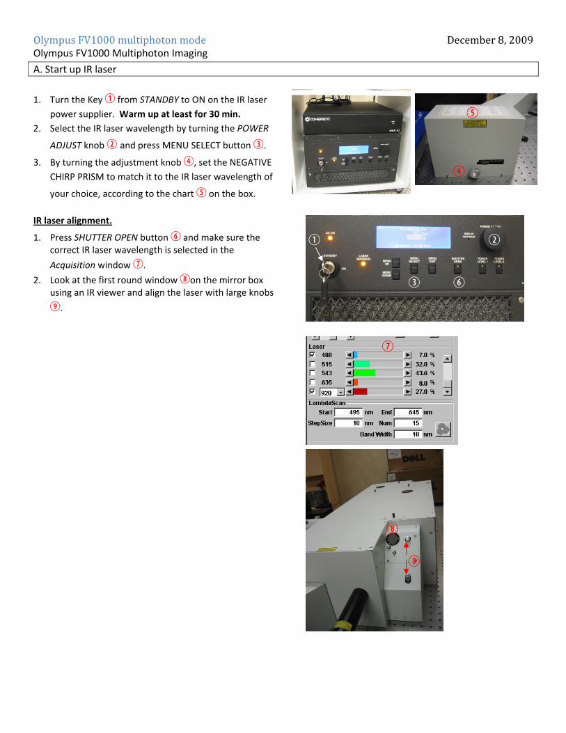
A. Start up IR laser
1. Turn the Key B from STANDBY to ON on the IR laser
power supplier. Warm up at least for 30 min.
2. Select the IR laser wavelength by turning the POWER
ADJUST knob C and press MENU SELECT button d.
3. By turning the adjustment knob e, set the NEGATIVE
CHIRP PRISM to match it to the IR laser wavelength of
your choice, according to the chart f on the box.
IR laser alignment.
1. Press SHUTTER OPEN button g and make sure the correct IR laser wavelength is selected in the
Acquisition window h.
2. Look at the first round window ion the mirror box using an IR viewer and align the laser with large knobs
j.
cb
d
f
g
e
h
i
j

Olympus FV1000 multiphoton mode December 8, 2009 B. Acquisition Setting
1. Click on Dye List button 1) and select Two Photon
1! button. (Check “Assign Dye Manually” 1@ to activate Two Photon button.)\
2. Drag the desired Dye to the appropriate external
detectors to assign the detector for your fluorescence
signal. (Depending on the filter cube type, the
detection wavelengths of BXD1 and BXD2 vary. BXD1
detects shorter wavelength than BXD2.)
3. Make sure that you inactivate visible lasers 1# (Otherwise, it will create lines on the images.) and that
the light path is set up for Two photon imaging; laser
unit2 1$, ExcitationDM RDM690 1%, and BXD 1^ in the LightPath & Dye window.
4. Select background change icon to darken the screen 1&.
5. Push in the lever 1* to direct light to external
detectors and set the filter wheel to “2” (R690) 1(. 6. Close the curtain and turn off the room light and start
imaging.
1)
1!
1@
1#
1^
1%
1$
1&
1*
1(