Embed Size (px)
Citation preview


Olympus Cube Assembly Procedure
2/11
Step Action
1.1.1 The cube assembly has two filter retainer rings; one is located on the Exciter side and one is on the Emitter side as shown below.
1.1.2 Remove both filter retainer rings from the cube assembly.
1.1.2.1 Each filter retaining ring has two slots where the spanner wrench blades are inserted for removal.
1.1.2.2 Spanner wrench blade locations.
Exciter Retaining Ring
Emitter Retaining Ring
Slots

Olympus Cube Assembly Procedure
3/11
Step Action
1.1.2.3 Spanner wrench blades inserted into the retaining ring slots.
1.1.2.4 To remove the retaining ring, insert the spanner wrench into the slots. Applying even pressure across the ring, carefully turn the ring counterclockwise to loosen and remove it from the cube assembly.
1.1.2.5 Repeat for the remaining retaining ring.
Olympus Cube Assembly Procedure
4/11
Step Action
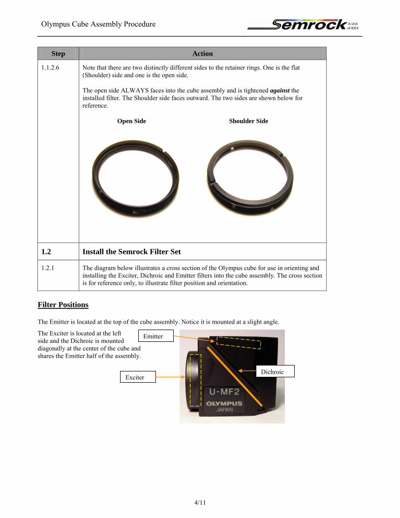
1.1.2.6 Note that there are two distinctly different sides to the retainer rings. One is the flat (Shoulder) side and one is the open side.
The open side ALWAYS faces into the cube assembly and is tightened against the installed filter. The Shoulder side faces outward. The two sides are shown below for reference.
Open Side Shoulder Side
1.2 Install the Semrock Filter Set
1.2.1 The diagram below illustrates a cross section of the Olympus cube for use in orienting and installing the Exciter, Dichroic and Emitter filters into the cube assembly. The cross section is for reference only, to illustrate filter position and orientation.
Filter Positions
The Emitter is located at the top of the cube assembly. Notice it is mounted at a slight angle.
The Exciter is located at the left side and the Dichroic is mounted diagonally at the center of the cube and shares the Emitter half of the assembly.
Dichroic
Emitter
Exciter

Olympus Cube Assembly Procedure
5/11
Filter Orientation
The filters are oriented in the assembly as follows:
The Exciter is mounted with its arrow pointing inward. The Dichroic reflective side is mounted facing the Exciter The Emitter is mounted with its arrow pointing outward.
Light passes through the cube in the direction of the arrows. Note: The Dichroic Reflective coating must face the Exciter as shown in the cross section diagram.
Dichroic reflective coating faces the Exciter

Olympus Cube Assembly Procedure
6/11
Step Action
1.2.2 Remove the two Phillips Head screws to separate the cube halves. Set the screws aside for reassembly later.
1.2.3 Separate the cube halves to prepare for assembly of the Semrock filter set.
Remove Screws
Olympus Cube Assembly Procedure
7/11
Step Action
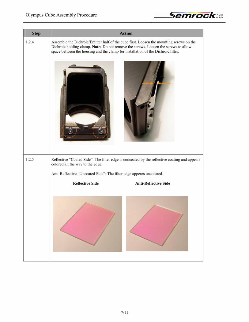
1.2.4 Assemble the Dichroic/Emitter half of the cube first. Loosen the mounting screws on the Dichroic holding clamp. Note: Do not remove the screws. Loosen the screws to allow space between the housing and the clamp for installation of the Dichroic filter.
1.2.5 Reflective “Coated Side”: The filter edge is concealed by the reflective coating and appears colored all the way to the edge.
Anti-Reflective “Uncoated Side”: The filter edge appears uncolored.
Reflective Side Anti-Reflective Side
Olympus Cube Assembly Procedure
8/11
Step Action
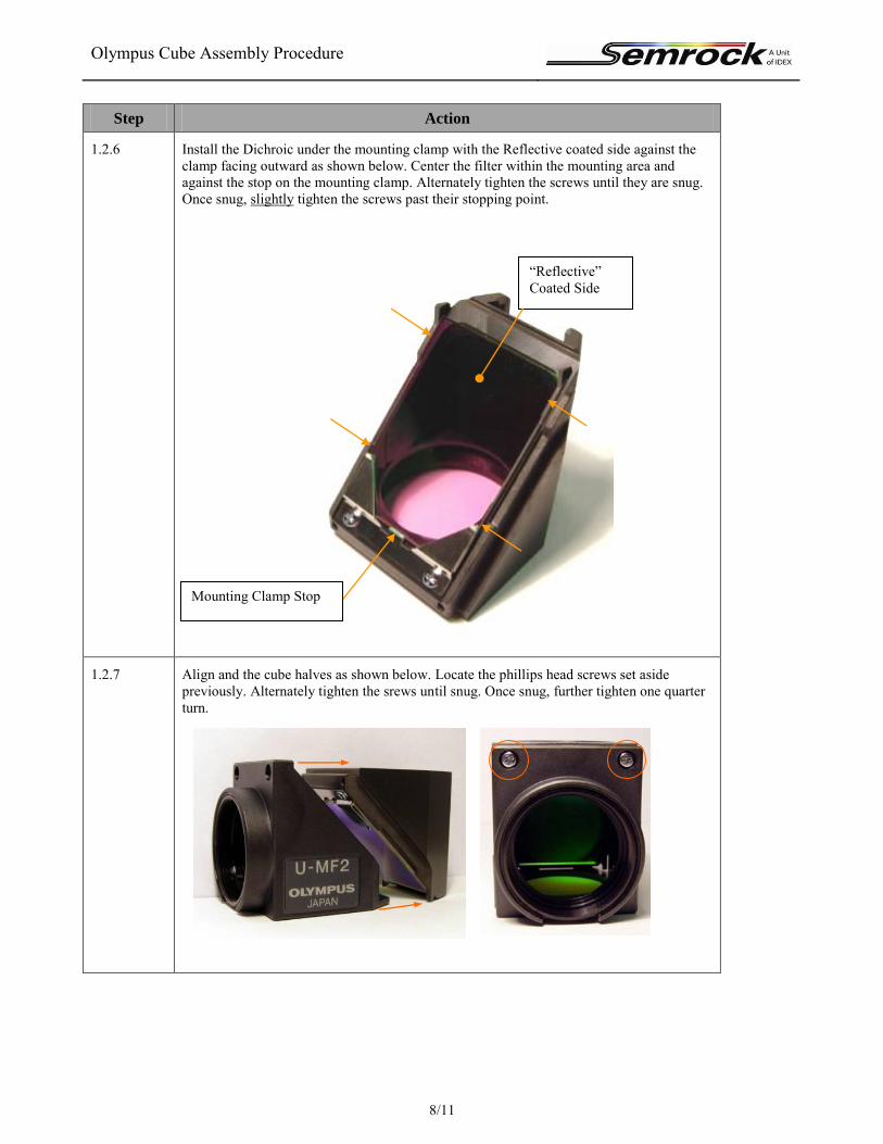
1.2.6 Install the Dichroic under the mounting clamp with the Reflective coated side against the clamp facing outward as shown below. Center the filter within the mounting area and against the stop on the mounting clamp. Alternately tighten the screws until they are snug. Once snug, slightly tighten the screws past their stopping point.
1.2.7 Align and the cube halves as shown below. Locate the phillips head screws set aside previously. Alternately tighten the srews until snug. Once snug, further tighten one quarter turn.
Mounting Clamp Stop
“Reflective” Coated Side

Olympus Cube Assembly Procedure
9/11
Step Action
1.2.8 Orient the Emitter with the arrow pointing away from the cube as shown below.
1.2.9 Place the filter inside the Emitter mounting area with the arrow pointing up.
Olympus Cube Assembly Procedure
10/11
Step Action
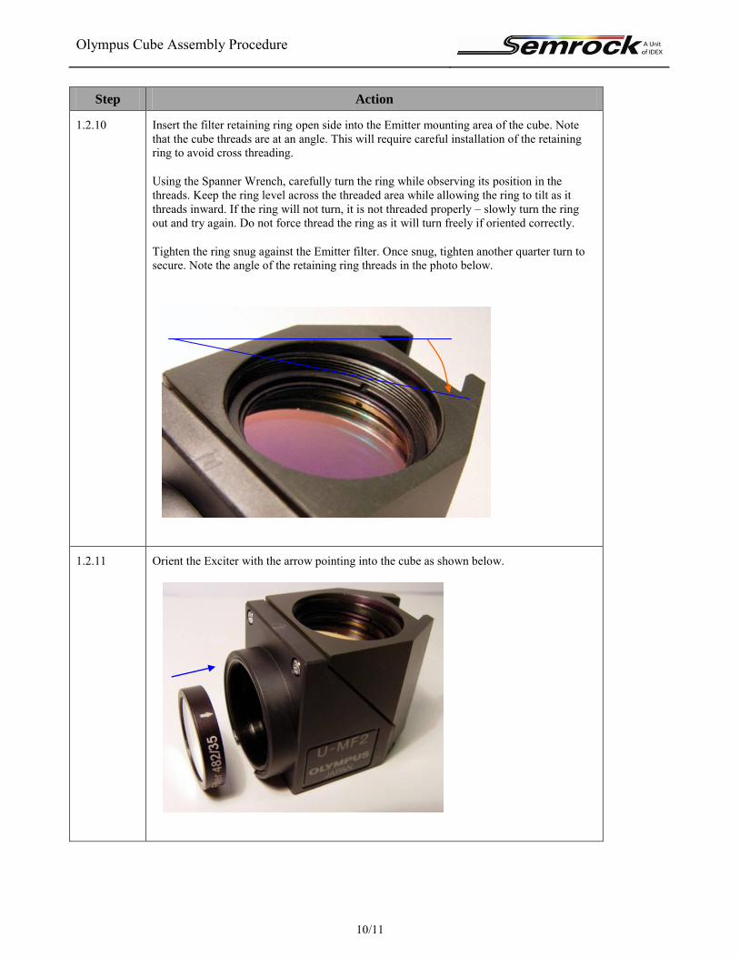
1.2.10 Insert the filter retaining ring open side into the Emitter mounting area of the cube. Note that the cube threads are at an angle. This will require careful installation of the retaining ring to avoid cross threading.
Using the Spanner Wrench, carefully turn the ring while observing its position in the threads. Keep the ring level across the threaded area while allowing the ring to tilt as it threads inward. If the ring will not turn, it is not threaded properly – slowly turn the ring out and try again. Do not force thread the ring as it will turn freely if oriented correctly.
Tighten the ring snug against the Emitter filter. Once snug, tighten another quarter turn to secure. Note the angle of the retaining ring threads in the photo below.
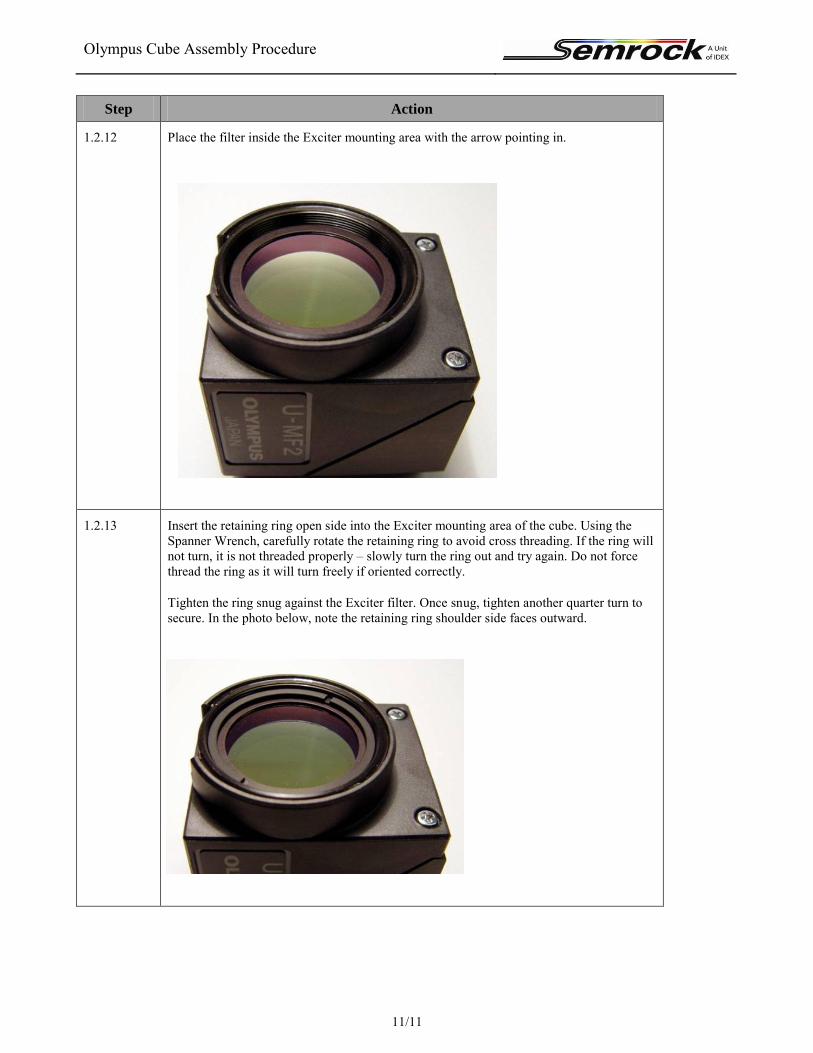
1.2.11 Orient the Exciter with the arrow pointing into the cube as shown below.
Olympus Cube Assembly Procedure
11/11
Step Action
1.2.12 Place the filter inside the Exciter mounting area with the arrow pointing in.
1.2.13 Insert the retaining ring open side into the Exciter mounting area of the cube. Using the Spanner Wrench, carefully rotate the retaining ring to avoid cross threading. If the ring will not turn, it is not threaded properly – slowly turn the ring out and try again. Do not force thread the ring as it will turn freely if oriented correctly.
Tighten the ring snug against the Exciter filter. Once snug, tighten another quarter turn to secure. In the photo below, note the retaining ring shoulder side faces outward.

Olympus Cube Assembly Procedure
12/11
Step Action
1.2.14 Completed Olympus OMF Cube Assembly.


![Supplementary Information: Spontaneous in- ight assembly of … · 2019. 5. 20. · magnetized cube, (c) uniformly [111] magnetized magnetic cube, (d) nine dipole model for [111]](https://img.pdfslide.us/doc/110x75/6103491b59433746e0180327/supplementary-information-spontaneous-in-ight-assembly-of-2019-5-20-magnetized.jpg)