Embed Size (px)
Citation preview
Olmsted Dam Construction Methodology Page 1 of 6
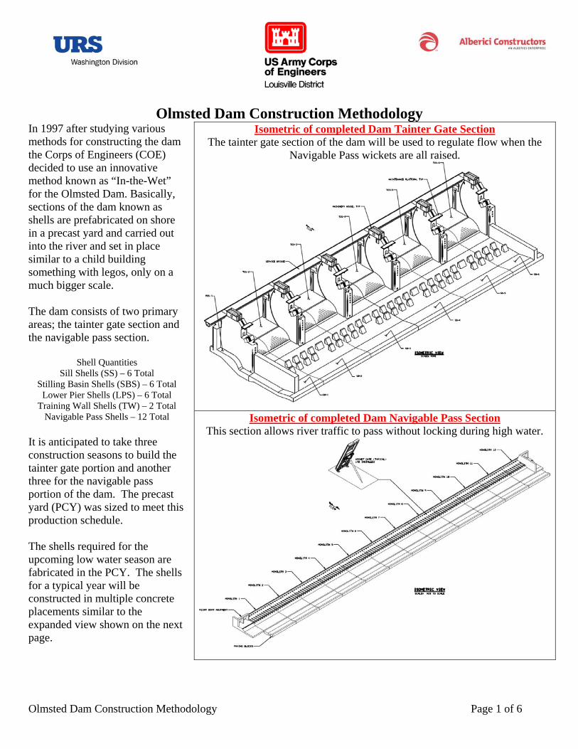
Olmsted Dam Construction Methodology In 1997 after studying various methods for constructing the dam the Corps of Engineers (COE) decided to use an innovative method known as “In-the-Wet” for the Olmsted Dam. Basically, sections of the dam known as shells are prefabricated on shore in a precast yard and carried out into the river and set in place similar to a child building something with legos, only on a much bigger scale. The dam consists of two primary areas; the tainter gate section and the navigable pass section.
Shell Quantities Sill Shells (SS) – 6 Total
Stilling Basin Shells (SBS) – 6 Total Lower Pier Shells (LPS) – 6 Total
Training Wall Shells (TW) – 2 Total Navigable Pass Shells – 12 Total
It is anticipated to take three construction seasons to build the tainter gate portion and another three for the navigable pass portion of the dam. The precast yard (PCY) was sized to meet this production schedule. The shells required for the upcoming low water season are fabricated in the PCY. The shells for a typical year will be constructed in multiple concrete placements similar to the expanded view shown on the next page.
Isometric of completed Dam Tainter Gate Section The tainter gate section of the dam will be used to regulate flow when the
Navigable Pass wickets are all raised.
Isometric of completed Dam Navigable Pass Section
This section allows river traffic to pass without locking during high water.
Olmsted Dam Construction Methodology Page 2 of 6
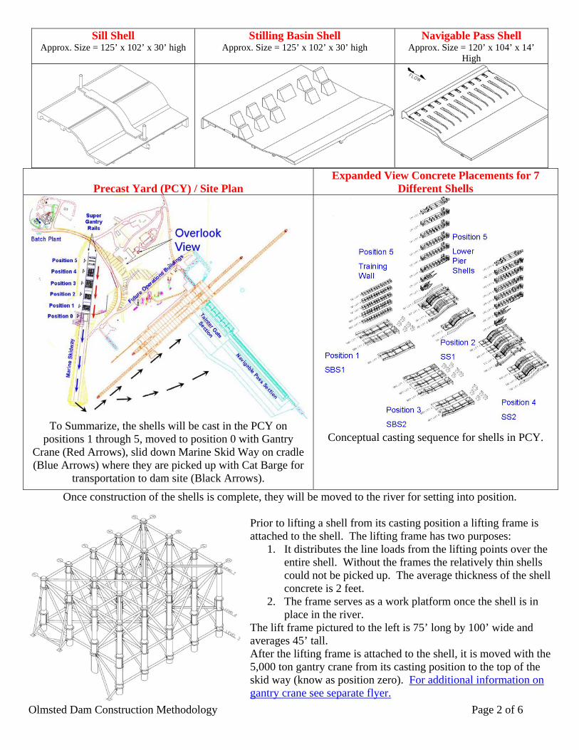
Precast Yard (PCY) / Site Plan
Expanded View Concrete Placements for 7 Different Shells
To Summarize, the shells will be cast in the PCY on positions 1 through 5, moved to position 0 with Gantry
Crane (Red Arrows), slid down Marine Skid Way on cradle (Blue Arrows) where they are picked up with Cat Barge for
transportation to dam site (Black Arrows).
Conceptual casting sequence for shells in PCY.
Once construction of the shells is complete, they will be moved to the river for setting into position. Prior to lifting a shell from its casting position a lifting frame is attached to the shell. The lifting frame has two purposes:
1. It distributes the line loads from the lifting points over the entire shell. Without the frames the relatively thin shells could not be picked up. The average thickness of the shell concrete is 2 feet.
2. The frame serves as a work platform once the shell is in place in the river.
The lift frame pictured to the left is 75’ long by 100’ wide and averages 45’ tall. After the lifting frame is attached to the shell, it is moved with the 5,000 ton gantry crane from its casting position to the top of the skid way (know as position zero). For additional information on gantry crane see separate flyer.
Sill Shell Approx. Size = 125’ x 102’ x 30’ high
Stilling Basin Shell Approx. Size = 125’ x 102’ x 30’ high
Navigable Pass Shell Approx. Size = 120’ x 104’ x 14’
High
Olmsted Dam Construction Methodology Page 3 of 6
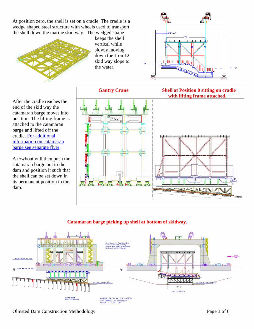
At position zero, the shell is set on a cradle. The cradle is a wedge shaped steel structure with wheels used to transport the shell down the marine skid way. The wedged shape
keeps the shell vertical while slowly moving down the 1 on 12 skid way slope to the water.
After the cradle reaches the end of the skid way the catamaran barge moves into position. The lifting frame is attached to the catamaran barge and lifted off the cradle. For additional information on catamaran barge see separate flyer. A towboat will then push the catamaran barge out to the dam and position it such that the shell can be set down in its permanent position in the dam.
Catamaran barge picking up shell at bottom of skidway.
Gantry Crane Shell at Position 0 sitting on cradle with lifting frame attached.
Olmsted Dam Construction Methodology Page 4 of 6
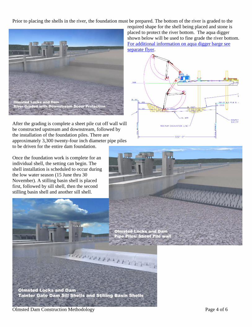
Prior to placing the shells in the river, the foundation must be prepared. The bottom of the river is graded to the
required shape for the shell being placed and stone is placed to protect the river bottom. The aqua digger shown below will be used to fine grade the river bottom. For additional information on aqua digger barge see separate flyer.
After the grading is complete a sheet pile cut off wall will be constructed upstream and downstream, followed by the installation of the foundation piles. There are approximately 3,300 twenty-four inch diameter pipe piles to be driven for the entire dam foundation. Once the foundation work is complete for an individual shell, the setting can begin. The shell installation is scheduled to occur during the low water season (15 June thru 30 November). A stilling basin shell is placed first, followed by sill shell, then the second stilling basin shell and another sill shell.
Olmsted Dam Construction Methodology Page 5 of 6
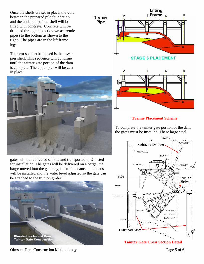
Once the shells are set in place, the void between the prepared pile foundation and the underside of the shell will be filled with concrete. Concrete will be dropped through pipes (known as tremie pipes) to the bottom as shown to the right. The pipes are in the lift frame legs. The next shell to be placed is the lower pier shell. This sequence will continue until the tainter gate portion of the dam is complete. The upper pier will be cast in place.
Tremie Placement Scheme To complete the tainter gate portion of the dam the gates must be installed. These large steel
gates will be fabricated off site and transported to Olmsted for installation. The gates will be delivered on a barge, the barge moved into the gate bay, the maintenance bulkheads will be installed and the water level adjusted so the gate can be attached to the trunion girder.
Tainter Gate Cross Section Detail
Olmsted Dam Construction Methodology Page 6 of 6
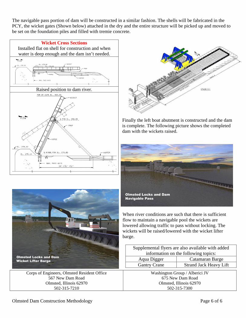
The navigable pass portion of dam will be constructed in a similar fashion. The shells will be fabricated in the PCY, the wicket gates (Shown below) attached in the dry and the entire structure will be picked up and moved to be set on the foundation piles and filled with tremie concrete.
Finally the left boat abutment is constructed and the dam is complete. The following picture shows the completed dam with the wickets raised.
When river conditions are such that there is sufficient flow to maintain a navigable pool the wickets are lowered allowing traffic to pass without locking. The wickets will be raised/lowered with the wicket lifter barge.
Corps of Engineers, Olmsted Resident Office 567 New Dam Road
Olmsted, Illinois 62970 502-315-7210
Washington Group / Alberici JV 675 New Dam Road
Olmsted, Illinois 62970 502-315-7300
Wicket Cross Sections Installed flat on shell for construction and when water is deep enough and the dam isn’t needed.
Raised position to dam river.
Supplemental flyers are also available with added information on the following topics:
Aqua Digger Catamaran Barge Gantry Crane Strand Jack Heavy Lift