Embed Size (px)
Citation preview

FEATURES
670 KHz operation
6.0-13.8 Vdc input voltage range
Programmable output voltage from 0.591-5.0 VDC
High power conversion effi ciency at 94%
Outstanding thermal derating performance
Over temperature and over current protection
On/Off control
SIP, 0.61 x 1.45 x 0.44 inches (15.5 x 36.8 x 11.2 mm)
Certifi ed to UL/EN/IEC 60950-1 safety standards, 2nd edition (pending)
RoHS-6 hazardous substance compliance
The OKR-T/20-W12-C is a miniature SIP non-isolated Point-of-Load (PoL) DC/DC power converter measuring only 0.61 x 1.45 x 0.44 inches (15.5 x 36.8 x 11.2 mm). The wide input range is 6.0 to 13.8 Volts DC. Based on 670 KHz synchronous buck topology, the high power conversion effi cient Point of Load (PoL) module features programmable output voltage and On/Off control, under voltage lock out (UVLO), overcurrent and over temperature protections. Certifi cation to UL/EN/ IEC 60950-1 safety standards (2nd edition) and RoHS-6 hazardous substance compliance is pending.
PRODUCT OVERVIEW
Figure 1. Connection Diagram
Typical unit
ExternalDC PowerSource
F1On/OffControl
CommonCommon
Open = OnClosed = Off
+Vin +Vout
Trim
Controller
Reference andError Amplifier
(Positive On/Off)
(pending)
www.murata-ps.com
www.murata-ps.com/support
For full details go towww.murata-ps.com/rohs
OKR-T/20-W12-CAdjustable Output 20-Amp SIP-mount DC-DC Converters
MDC_OKR-T/20-W12-C.A01 Page 1 of 14
PART NUMBER STRUCTURE
➀ Dimensions are in inches (mm).
➁ Ripple and Noise is shown at Vout=1V. See specs for details.
➂ All specifi cations are at nominal line voltage, Vout= 5V and full load, +25 deg.C.
unless otherwise noted. Output capacitors are 3 22μF and 2 47μF ceramic. Input cap is 22 μF. See detailed specifi cations. I/O caps are necessary for our test equipment and may not be needed for your application.
Vin must be 2V or higher than Vout for 3.3 to 5V outputs.
PERFORMANCE SPECIFICATIONS SUMMARY AND ORDERING GUIDE
Root Model
Output Input
Effi ciency
Package
VOUT
(Volts)
IOUT
(Amps
max)
Power
(Watts)
R/N (mVp-p) Regulation (Max.)
VIN Nom.
(Volts)
Range
(Volts)
IIN,
no load
(mA)
IIN,
full load
(Amps) Dimensions: inches (mm)Max. Line Load Min. Typ.
OKR-T/20-W12-C 0.591-5 20 100 30 ±0.3% ±0.5% 12 6.0-13.8 100 8.9 92% 94%0.61 x 1.45 x 0.44
(15.5 x 36.8 x 11.2)
Output Voltage Range
T = Trimmable, 0.591-5 Volts
Wide Input Voltage Range
W12 = 6.0-13.8 Volts
W12
Okami Non-isolated PoL
Maximum Rated Output
Current in Amps
SIP-Mount
OK R - / -T 20 C-
RoHS Hazardous
Substance Compliance
C = RoHS-6 (does not claim EU RoHS exemption 7b–lead in solder)
www.murata-ps.com/support
OKR-T/20-W12-CAdjustable Output 20-Amp SIP-mount DC-DC Converters
MDC_OKR-T/20-W12-C.A01 Page 2 of 14

Input
Input Voltage Range See Ordering Guide. See note 15.
Recommended External Fuse 30 Amps
Reverse Polarity Protection (Note 9) None. Use an external fuse.
Isolation Not isolated. The input and output commons are internally connected.
Start-Up Voltage 5.4 Volts
Undervoltage Shutdown 4.4 Volts
Refl ected (Back) Ripple Current (Note 2) 10 mA pk-pk
Internal Input Filter Type Capacitive
Input Current:
Full Load Conditions See Ordering Guide
Inrush Transient 1 A2Sec.
Shutdown Mode (Off, UV, OT) TBD mA
Output Short Circuit TBD mA
No Load, 5V out 100 mA
Low Line (Vin=Vmin, 5Vout) 15.0 Amps
Remote On/Off Control
Positive Logic ON = +2 V. to +Vin max., 100KΩ pulldown to ground OFF = open pin or –0.3 to +0.4 V. max. Current 1 mA max.
Turn-on Time:
Remote On to Vout Regulated(all output voltages) 4 mSec
Output
Minimum Loading No minimum load
Output Current Range 0 to 20 Amps (to rated specifi cations)
Accuracy (50% load, no trim) ±2 % of Vnom
Temperature Coeffi cient ±0.02% per °C. of Vout range
Ripple/Noise (20 MHz bandwidth) 25 mV pk-pk max.
Line/Load Regulation See Ordering Guide and note 10
Effi ciency See Ordering Guide and performance graphs
Minimum Capacitive Loading 150 μF CeramicMaximum Capacitive Loading 1500 μF CeramicNote: Phase margin of 50° or greater is maintained with a nominal input voltage (12V) and the capacitive loading parameters specifi ed above.
Current Limit Inception 26 Amps (98% of Vout setting, after warm up)
Short Circuit Mode (Notes 6, 12)
Short Circuit Current Output 0.6 Amp Protection Method Hiccup autorecovery upon overload removal. (Note 8) Short Circuit Duration Continuous, no damage (output shorted to ground)
Overvoltage protection None
Performance/Functional Specifi cationsAll specifi cations are typical unless noted See Note 1.
Dynamic Characteristics
Switching Frequency 670 KHz
Environmental
Calculated MTBF (Note 4) OKR-T/20-W12-C 8,724,722 hours (4a) OKR-T/20-W12-C 10,772,399 hours (4b)
Operating Temperature Range
(Ambient temp., Vout=5 V., vertical mount) Full power, see derating curves -40 to +85 °C.
Operating PC Board Range, no derating -40 to +125 °C.
Storage Temperature Range -55 to +125 °C.
Thermal Protection/Shutdown +130 °C.
Relative Humidity to 85%/+85 °C.
Restriction of Hazardous Substances RoHS-6 (does not claim EU RoHS exemption 7b–lead in solder)
Physical
Outline Dimensions See Mechanical Specifi cations
Weight 0.07 ounces (2 grams)
Safety Certifi ed to UL/cUL 60950-1 CSA-C22.2 No. 60950-1 IEC/EN 60950-1, 2nd edtion
Absolute Maximum Ratings
Input Voltage Continuous or transient 15 Volts max.
Output Power 100 Watts max.
On/Off Control 0 Volts. min. to +Vin. max.
Input Reverse Polarity Protection See Fuse section
Output Current Current-limited. Devices can withstand sustained short circuit without damage.
Storage Temperature -40 to +125 deg. C.
Absolute maximums are stress ratings. Exposure of devices to greater than any of these conditions may adversely affect long-term reliability. Proper operation under conditions other than those listed in the Performance/Functional Specifi cations Table is not implied or recommended.
CAUTION: This product is not internally fused. To comply with safety agency certifi cations and to avoid injury to personnel or equipment, the user must supply an external fast-blow fuse to the input terminals.
(1) All specifi cations are typical unless noted. General conditions for Specifi cations are +25 deg.C, Vin=nominal, Vout=nominal (no trim installed), full rated load. Adequate airfl ow
Capacitive Loading Peak Deviation Settling Time
130 μF Ceramic 180mV 30 μsec
430 μF Ceramic + 470μ Poscap 120mV 40 μsec
www.murata-ps.com/support
OKR-T/20-W12-CAdjustable Output 20-Amp SIP-mount DC-DC Converters
MDC_OKR-T/20-W12-C.A01 Page 3 of 14

must be supplied for extended testing under power.
All models are tested and specifi ed with external 3 22μF and 2 47μF output capacitors and a 22 μF external input capacitor. All capacitors are low ESR types. Caps are layout dependent These capacitors are necessary to accommodate our test equipment and may not be required in your applications. All models are stable and regulate within spec under no-load conditions.
(2) Input Back Ripple Current is tested and specifi ed over a 5 Hz to 20 MHz bandwidth. Input fi ltering is Cin=2 x 100 μF, 100V tantalum, Cbus=1000 μF, 100V electrolytic, Lbus=1 μH. All caps are low ESR types.
(3) Note that Maximum Power Derating curves indicate an average current at nominal input voltage. At higher temperatures and/or lower airfl ow, the DC/DC converter will tolerate brief full current outputs if the total RMS current over time does not exceed the Derating curve. All Derating curves are presented at sea level altitude. Be aware of reduced power dissipation with increasing altitude.
(4a) Mean Time Before Failure is calculated using the Telcordia (Belcore) SR-332 Method 1, Case 3, ground fi xed conditions, Tpcboard=+25 ˚C, full output load, natural air convec-tion.
(4b) Mean Time Before Failure is calculated using the MIL-HDBK-217N2 method, ground benign, +25ºC., full output load, natural convection.
(5) The On/Off Control is normally controlled by a switch or open collector or open drain tran-sistor. But it may also be driven with external logic or by applying appropriate external voltages which are referenced to Input Common.
(6) Short circuit shutdown begins when the output voltage degrades approximately 2% from the selected setting.
(7) The outputs are not intended to sink appreciable reverse current.
(8) “Hiccup” overcurrent operation repeatedly attempts to restart the converter with a brief, full-current output. If the overcurrent condition still exists, the restart current will be
removed and then tried again. This short current pulse prevents overheating and damag-ing the converter. Once the fault is removed, the converter immediately recovers normal operation.
(9) Input Fusing: If reverse polarity is accidentally applied to the input, to ensure reverse input protection with full output load, always connect an external input fast-blow fuse in series with the +Vin input. Use approximately twice the full input current rating with nominal input voltage.
(10) Regulation specifi cations describe the deviation as the line input voltage or output load current is varied from a nominal midpoint value to either extreme.
(11) CAUTION: Since the converter is mounted on the end by its pins, do not subject it to high vibration, shock or acceleration.
(12) Output current limit and short circuit protection is non-latching. When the overcurrent fault is removed, the converter will immediately recover.
(13) Do not exceed maximum power specifi cations when adjusting the output trim. All pub-lished specifi cations are listed at rated nominal output current using published Derating curves. The maximum power specifi cations indicate brief operation before overcurrent shutdown occurs. Note particularly that current must be limited at higher output voltage in order to comply with maximum power requirements.
(14) The input and output are not isolated. They share a single COMMON power and signal return.
(15) Vin must be 2V or higher than Vout for 3.3 to 5V outputs: Vin >= (2V + Vout)
Notes
Trim Connections
RTRIM
RLOADTrim
+VOUT
Ground
RTRIM (kΩ) = 1.182 VOUT − 0.591
Output Voltage Adustment
The output voltage may be adjusted over a limited range by connecting an external trim resistor (Rtrim) between the Trim pin and Ground. The Rtrim resistor must be a 1/10 Watt precision metal fi lm type, ±0.5% accuracy or better with low temperature coeffi cient, ±100 ppm/oC. or better. Mount the resistor close to the converter with very short leads or use a surface mount trim resistor.
In the tables below, the calculated resistance is given. Do not exceed the specifi ed limits of the output voltage or the converter’s maximum power rating when applying these resistors. Also, avoid high noise at the Trim input. However, to prevent instability, you should never connect any capaci-tors to Trim.
OKR-T/20-W12-C
Output Voltage Calculated Rtrim (Ω)
5 V. 268
3.3 V. 436
2.5 V. 619
1.8 V. 978
1.5 V. 1300
1.2 V. 1940
1.0 V. 2890
0.591 V. ∞ (open)
RTRIM (k) = _____________(VOUT – 0.591)
1.182
Resistor Trim Equation, OKR-T/20-W12-C models:
www.murata-ps.com/support
OKR-T/20-W12-CAdjustable Output 20-Amp SIP-mount DC-DC Converters
MDC_OKR-T/20-W12-C.A01 Page 4 of 14

PERFORMANCE DATA
Maximum Current Temperature Derating at Sea Level(Vout = 5.0V; Vin = 12V, airfl ow is from pin 8 to pin 1)
Thermal Reference Point
Maximum Current Temperature Derating at Sea Level(Vout = 1.0V; Vin = 12V, airfl ow is from pin 8 to pin 1)
Maximum Current Temperature Derating at Sea Level(Vout = 2.5V; Vin = 12V, airfl ow is from pin 8 to pin 1)
8
9
10
11
12
13
14
15
16
17
18
19
20
21
30 35 40 45 50 55 60 65 70 75 80 85
Ou
tpu
t C
urr
en
t (A
mp
s)
Ambient Temperature (°C)
0.5 m/s (100 LFM)1.0 m/s (200 LFM)1.5 m/s (300 LFM)2.0 m/s (400 LFM)
8
9
10
11
12
13
14
15
16
17
18
19
20
21
30 35 40 45 50 55 60 65 70 75 80 85
Ou
tpu
t C
urr
en
t (A
mp
s)
Ambient Temperature (°C)
0.5 m/s (100 LFM)1.0 m/s (200 LFM)1.5 m/s (300 LFM)2.0 m/s (400 LFM)
8
9
10
11
12
13
14
15
16
17
18
19
20
21
30 35 40 45 50 55 60 65 70 75 80 85
Ou
tpu
t C
urr
en
t (A
mp
s)
Ambient Temperature (°C)
0.5 m/s (100 LFM)1.0 m/s (200 LFM)1.5 m/s (300 LFM)2.0 m/s (400 LFM)
Effi ciency vs. Line Voltage and Load Current @ +25°C
60
65
70
75
80
85
90
95
100
0 2 4 6 8 10 12 14 16 18 20
Load Current (Amps)
Effi
cie
ncy
(%
)
Vout=5vVout=3.3vVout=2.5vVout=1.8vVout=1v
www.murata-ps.com/support
OKR-T/20-W12-CAdjustable Output 20-Amp SIP-mount DC-DC Converters
MDC_OKR-T/20-W12-C.A01 Page 5 of 14

PERFORMANCE DATA
Step Load Transient Response (Vin=12V, Vout=1.0V, Iload=0-10A,10A/us)Iload 0-50-0% 130μF
Step Load Transient Response (Vin=12V, Vout=1.0V, Iload=0-10A,10A/us)Iload 50-100-50% 130μF
On/Off Enable Startup (Vout=1V, Vin=12 V, Iload=0A)
Step Load Transient Response (Vin=12V, Vout=1.0V, Iload=0-10A,10A/us)Iload 0-50-0% 130μF
Step Load Transient Response (Vin=12V, Vout=1.0V, Iload=0-10A,10A/us)Iload 50-100-50% 130μF
www.murata-ps.com/support
OKR-T/20-W12-CAdjustable Output 20-Amp SIP-mount DC-DC Converters
MDC_OKR-T/20-W12-C.A01 Page 6 of 14

PERFORMANCE DATA
Step Load Transient Response (Vin=12V, Vout=1.0V, Iload=0-10A,10A/us)Iload 0-50-0% 900μF
Step Load Transient Response (Vin=12V, Vout=1.0V, Iload=0-10A,10A/us)Iload 50-100-50% 900μF
Step Load Transient Response (Vin=12V, Vout=1.0V, Iload=0-10A,10A/us)Iload 0-50-0% 900μF
Step Load Transient Response (Vin=12V, Vout=1.0V, Iload=0-10A,10A/us)Iload 50-100-50% 900μF
www.murata-ps.com/support
OKR-T/20-W12-CAdjustable Output 20-Amp SIP-mount DC-DC Converters
MDC_OKR-T/20-W12-C.A01 Page 7 of 14

Input Fusing
Certain applications and/or safety agencies may require fuses at the inputs of power conversion components. Fuses should also be used when there is the possibility of sustained input voltage reversal which is not current-limited. For greatest safely, we recommend a fast blow fuse installed in the ungrounded input supply line.
The installer must observe all relevant safety standards and regulations. For safety agency approvals, install the converter in compliance with the end-user safety standard, i.e. IEC/EN/UL 60950-1.
Input Under-Voltage Shutdown and Start-Up Threshold
Under normal start-up conditions, converters will not begin to regulate properly until the ramping-up input voltage exceeds and remains at the Start-Up Threshold Voltage (see Specifi cations). Once operating, converters will not turn off until the input voltage drops below the Under-Voltage Shutdown Limit. Subsequent restart will not occur until the input voltage rises again above the Start-Up Threshold. This built-in hysteresis prevents any unstable on/off opera-tion at a single input voltage.
Users should be aware however of input sources near the Under-Voltage Shutdown whose voltage decays as input current is consumed (such as capacitor inputs), the converter shuts off and then restarts as the external capacitor recharges. Such situations could oscillate. To prevent this, make sure the operating input voltage is well above the UV Shutdown voltage AT ALL TIMES.
Start-Up Time
Assuming that the output current is set at the rated maximum, the Vin to Vout Start-Up Time (see Specifi cations) is the time interval between the point when the ramping input voltage crosses the Start-Up Threshold and the fully loaded regulated output voltage enters and remains within its specifi ed accuracy band. Actual measured times will vary with input source impedance, external input capacitance, input voltage slew rate and fi nal value of the input voltage as it appears at the converter.
These converters include a soft start circuit to moderate the duty cycle of its PWM controller at power up, thereby limiting the input inrush current.
The On/Off Remote Control interval from On command to Vout regulated assumes that the converter already has its input voltage stabilized above the Start-Up Threshold before the On command. The interval is measured from the On command until the output enters and remains within its specifi ed accuracy band. The specifi cation assumes that the output is fully loaded at maximum rated current. Similar conditions apply to the On to Vout regulated specifi cation such as external load capacitance and soft start circuitry.
Recommended Input Filtering
The user must assure that the input source has low AC impedance to provide dynamic stability and that the input supply has little or no inductive content, including long distributed wiring to a remote power supply. The converter will operate with no additional external capacitance if these conditions are met.
For best performance, we recommend installing a low-ESR capacitor immediately adjacent to the converter’s input terminals. The capacitor should be a ceramic type such as the Murata GRM32 series or a polymer type. Initial
TECHNICAL NOTES suggested capacitor values are 10 to 22 μF, rated at twice the expected maxi-mum input voltage. Make sure that the input terminals do not go below the undervoltage shutdown voltage at all times. More input bulk capacitance may be added in parallel (either electrolytic or tantalum) if needed.
Recommended Output Filtering
The minimum external output capacitance required for proper operation is 3 22μF and 2 47μF ceramic type. The maximum external output capacitance is 1500μF. Operating outside of these minimum and maximum limits may affect the performance of the unit.
Input Ripple Current and Output Noise
All models in this converter series are tested and specifi ed for input refl ected ripple current and output noise using designated external input/output compo-nents, circuits and layout as shown in the fi gures below. In the fi gure below, the Cbus and Lbus components simulate a typical DC voltage bus. Please note that the values of Cin, Lbus and Cbus will vary according to the specifi c converter model.
Minimum Output Loading Requirements
All models regulate within specifi cation and are stable under no load to full load conditions. Operation under no load might however slightly increase output ripple and noise.
CINVIN CBUS
LBUS
CIN = 2 x 100μF, ESR < 700mΩ @ 100kHz
CBUS = 1000μF, ESR < 100mΩ @ 100kHz
LBUS = 1μH
+VIN
-VIN
CURRENTPROBE
TO OSCILLOSCOPE
+–+–
Figure 3. Measuring Input Ripple Current
C1
C1 = 0.1μF
C2 = 50μF
LOAD 2-3 INCHES (51-76mm) FROM MODULE
C2 RLOADSCOPE
+VOUT
-VOUT
Figure 4. Measuring Output Ripple and Noise (PARD)
www.murata-ps.com/support
OKR-T/20-W12-CAdjustable Output 20-Amp SIP-mount DC-DC Converters
MDC_OKR-T/20-W12-C.A01 Page 8 of 14
Thermal Shutdown
To prevent many over temperature problems and damage, these converters include thermal shutdown circuitry. If environmental conditions cause the temperature of the DC/DC’s to rise above the Operating Temperature Range up to the shutdown temperature, an on-board electronic temperature sensor will power down the unit. When the temperature decreases below the turn-on threshold, the converter will automatically restart. There is a small amount of hysteresis to prevent rapid on/off cycling. The temperature sensor is typically located adjacent to the switching controller, approximately in the center of the unit. See the Performance and Functional Specifi cations.
CAUTION: If you operate too close to the thermal limits, the converter may shut down suddenly without warning. Be sure to thoroughly test your applica-tion to avoid unplanned thermal shutdown.
Temperature Derating Curves
The graphs in this data sheet illustrate typical operation under a variety of conditions. The Derating curves show the maximum continuous ambient air temperature and decreasing maximum output current which is acceptable under increasing forced airfl ow measured in Linear Feet per Minute (“LFM”). Note that these are AVERAGE measurements. The converter will accept brief increases in current or reduced airfl ow as long as the average is not exceeded.
Note that the temperatures are of the ambient airfl ow, not the converter itself which is obviously running at higher temperature than the outside air. Also note that very low fl ow rates (below about 25 LFM) are similar to “natural convection,” that is, not using fan-forced airfl ow.
Murata Power Solutions makes Characterization measurements in a closed cycle wind tunnel with calibrated airfl ow. We use both thermocouples and an infrared camera system to observe thermal performance.
CAUTION: If you routinely or accidentally exceed these Derating guidelines, the converter may have an unplanned Over Temperature shut down. Also, these graphs are all collected at slightly above Sea Level altitude. Be sure to reduce the derating for higher density altitude.
Output Current Limiting
Current limiting inception is defi ned as the point at which full power falls below the rated tolerance. See the Performance/Functional Specifi cations. Note par-ticularly that the output current may briefl y rise above its rated value in normal
operation as long as the average output power is not exceeded. This enhances reliability and continued operation of your application. If the output current is too high, the converter will enter the short circuit condition.
Output Short Circuit Condition
When a converter is in current-limit mode, the output voltage will drop as the output current demand increases. If the output voltage drops too low (approxi-mately 98% of nominal output voltage for most models), the magnetically coupled voltage used to develop primary side voltages will also drop, thereby shutting down the PWM controller. Following a time-out period, the PWM will restart, causing the output voltage to begin ramping up to its appropriate value. If the short-circuit condition persists, another shutdown cycle will initiate. This rapid on/off cycling is called “hiccup mode”. The hiccup cycling reduces the average output current, thereby preventing excessive internal temperatures and/or component damage. A short circuit can be tolerated indefi nitely.
The “hiccup” system differs from older latching short circuit systems because you do not have to power down the converter to make it restart. The system will automatically restore operation as soon as the short circuit condi-tion is removed.
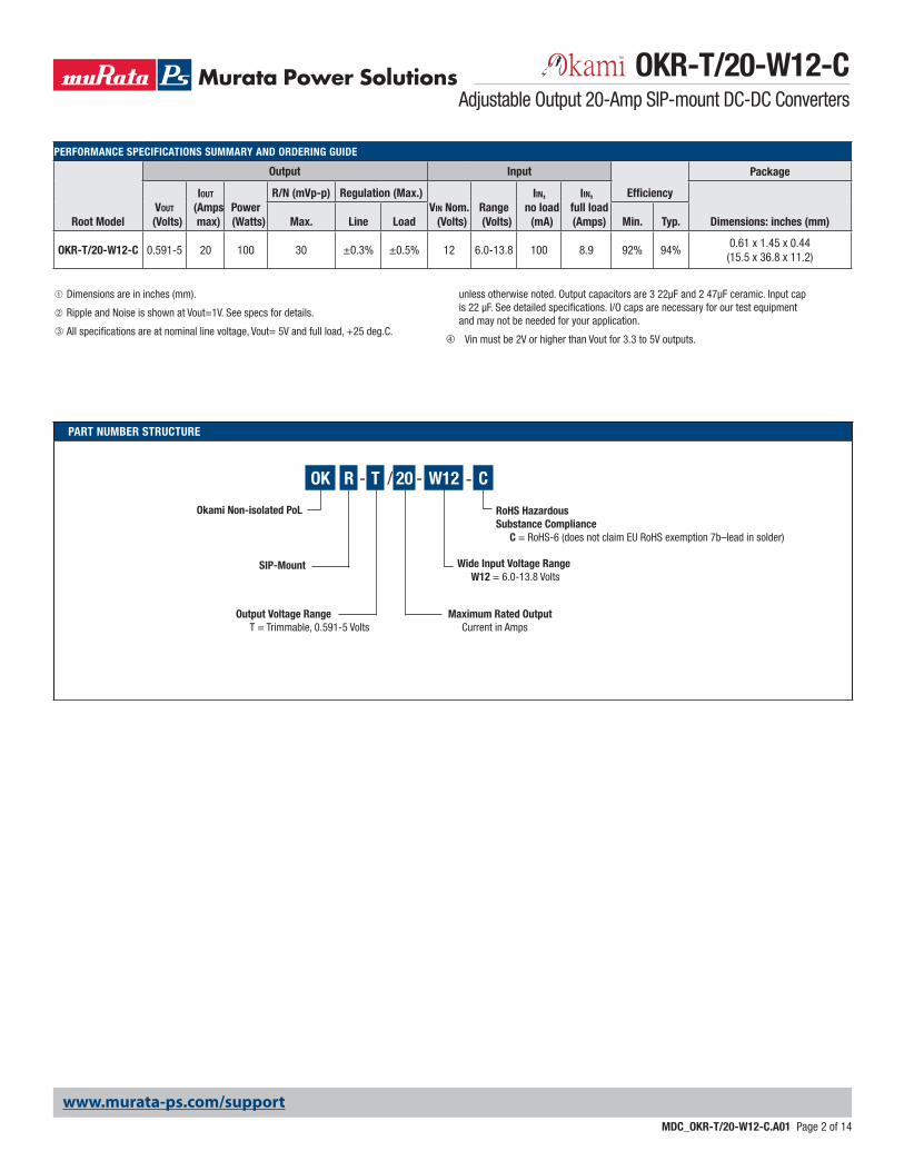
External Enable On/Off Control (see fi gure 5)
The forced On/Off enable option uses positive logic for the external control. The converter may be powered ON by applying a positive voltage (logic HI) between the On/Off pin and the negative power input (-Vin). This positive voltage is referred to –Vin and must be in the range of at least +2.0V and not to exceed the power supply input voltage (+Vin). The current drain is 12 mA max. when turned on.
If the On/Off pin is left open, an internal 100 Kilohm pulldown resistor will turn the converter OFF. The OFF condition may also be commanded by ground-ing the pin or from an external logic LO voltage not to exceed +0.4 Volts. All voltages are referred to the –Vin negative power input.
If you wish to control the On/Off circuit by external logic rather than a switch, carefully compare your logic threshold voltages with that of the On/Off input.
The circuit below indicates the equivalent input. Please avoid false signals from ground bounce errors on the On/Off control.
Figure 5. On/Off Control Circuit
Vin
www.murata-ps.com/support
OKR-T/20-W12-CAdjustable Output 20-Amp SIP-mount DC-DC Converters
MDC_OKR-T/20-W12-C.A01 Page 9 of 14

MECHANICAL SPECIFICATIONS
INPUT/OUTPUT CONNECTIONS
OKR-T/20-W12-C
Pin Function
J1-1 +VOUT
J1-2 Output TrimJ1-3 PGNDJ1-4 PGOOD
J1-5 EnableJ1-6 +VIN
J1-7 (+) Remote SenseJ1-8 (-) Remote SenseJ1-9 Mechanical SupportJ1-10 Mechanical Support
Third Angle Projection
Dimensions are in inches (mm shown for ref. only).
Components are shown for reference only.
Tolerances (unless otherwise specified):.XX ± 0.02 (0.5).XXX ± 0.010 (0.25)Angles ± 2˚
[2.06]0.081
[6.93]0.27
[5.7]0.22
[34.29]1.350
[4.45]0.175
[2.54]0.100
[12.70]0.500
[26.67]1.050
[1.27]0.050
[3.18]0.125REF
END VIEW
[11.18]0.44
REF0.130[3.30]
0.030[0.76]
0.053[1.35]
2x
8x
[2.79]0.110
FRONT VIEW
10 9
7 16 5 4 3 28
[3.30]0.130
1.45[36.8]
0.61[15.5]
2x[1.27]0.050
200μ" MIN MATTE TIN OVER NICKEL (40μ" MIN)FINISH: (ALL HEADER PINS)
MATERIAL:0.030 HEADER PINS: COPPER ALLOY
SUPPORT PINS: TIN PLATED BRASS
TOP VIEW
[11.2]0.44REF
ISOMETRICVIEW
www.murata-ps.com/support
OKR-T/20-W12-CAdjustable Output 20-Amp SIP-mount DC-DC Converters
MDC_OKR-T/20-W12-C.A01 Page 10 of 14

MECHANICAL SPECIFICATIONS
Third Angle Projection
Dimensions are in inches (mm shown for ref. only).
Components are shown for reference only.
Tolerances (unless otherwise specified):.XX ± 0.02 (0.5).XXX ± 0.010 (0.25)Angles ± 2˚
(12.0)0.47
(1.52)0.060
(VIEW FROM TOP)RECOMMENDED FOOTPRINT
(12.70)
0.081(2.06)
0.175(4.45)
0.100 (2.54)0.500
2x .078±.003
8x .035±.003
1.350(34.29)
0.950(24.13)
5x
1.47(37.3)
0.295(7.49)REF 0.245 (6.22)
7 16 5 2348
910
www.murata-ps.com/support
OKR-T/20-W12-CAdjustable Output 20-Amp SIP-mount DC-DC Converters
MDC_OKR-T/20-W12-C.A01 Page 11 of 14
STANDARD PACKAGING
Third Angle Projection
Dimensions are in inches (mm shown for ref. only).
Components are shown for reference only.
Tolerances (unless otherwise specified):.XX ± 0.02 (0.5).XXX ± 0.010 (0.25)Angles ± 2˚
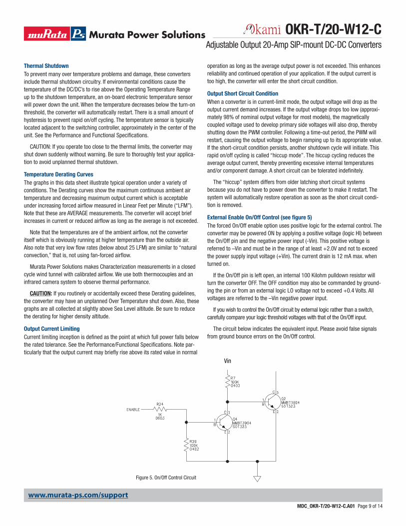
STANDARD PACKAGING
CORRUGATEDCARTON
EACH STATIC DISSIPATIVE POLYETHYLENE FOAM TRAY
ACCOMMODATES 35 CONVERTERS
IN A 5 X 7 ARRAY
FOAM PADS
266.7±6.410.50±0.25 11.00±0.25
279.4±6.4
108.0±6.44.25±0.25
CLOSED HEIGHT
35 UNITS PER TRAY3 TRAYS PER CARTON
MPQ=105 UNITS
www.murata-ps.com/support
OKR-T/20-W12-CAdjustable Output 20-Amp SIP-mount DC-DC Converters
MDC_OKR-T/20-W12-C.A01 Page 12 of 14

Additional Performance/Functional Specifi cations
General Conditions for Device under Test unless otherwise specifi ed: Ambient Temperature +25°C Vin typical; Vout nominal load With an external 22μF input capacitor and an external 50μF ceramic capacitor Note: External Capacitors are application/layout dependent and may not be required, as the internal Capacitors are rated to handle input/output RMS ripple currents.INPUT: MIN. TYP MAX. UNITS
Internal (built-in) FILTER: C-TYPEExternal Input FUSE (Recommended): 30 AInput Reverse Polarity Protection: NAVOLTAGE:
Operating Input Voltage Range: *** 6.0 12.0 13.8 Vdc Max. Voltage (Continuous or Transient): 15 Vdc Start up Voltage: 5.2 5.4 5.6 Vdc Undervoltage Shutdown: 4.2 4.4 4.6 Vdc Overvoltage Shutdown: NA Vdc*** Vin ≥ Vout +2V for 3.3V and 5V ***
CURRENT:
Input Current: (5Vo set) 8.8 9.3 A Low Line Input Current ( Vin @ Min., 5Vout): 15 15.6 A Short Circuit Input Current: 60 mA Inrush Transient: 0.4 A2 sec No Load Input Current (5V, Iout @ 0): 100 150 mA No Load Input Current (1V, Iout @ 0): 70 110 mA Shut-Down Mode Input Current: 5 mA Back Ripple Current: 10 mAp-p Measured at module input: Cin = 100μF, Cbus = 1000μF, Lbus = 1μH
Back Ripple Current (no fi ltering): 175 mAp-pGENERAL & SAFETY: MIN. TYP. MAX. UNITS
EFFICIENCY: @ Vin nom, 5Vout 92.0 94.2 % @ Vin min, 5Vout 93.5 95.0 %EFFICIENCY: @ Vin nom, 3.3Vout 90.5 92.2 %EFFICIENCY: @ Vin nom, 2.5Vout 88.5 90.5 %EFFICIENCY: @ Vin nom, 1.8Vout 86.0 88.0 %EFFICIENCY: @ Vin nom, 1.5Vout 84.0 86.4 %EFFICIENCY: @ Vin nom, 1.2Vout 81.5 83.5 %EFFICIENCY: @ Vin nom, 1Vout 79.5 81.5 %EFFICIENCY: @ Vin nom, 0.59Vout 71.5 73.5 %SWITCHING FREQUENCY: 670 kHzTURN ON TIME:
Remote On to Vout Regulated (all output voltages) 4 10 msISOLATION: NON ISOLATEDSAFETY (Designed to meet following Requirements):
UL60950, CSA-C22.2 No.60950 Yes IEC/EN60950 YesCALCULATED MTBF: TBD Hours (Belcore, Telcordia SR-332, Method 1, Class 3, Gf, Tcase xx°C, Full Load )
OUTPUT: MIN. NOM. MAX. UNITS
www.murata-ps.com/support
OKR-T/20-W12-CAdjustable Output 20-Amp SIP-mount DC-DC Converters
MDC_OKR-T/20-W12-C.A01 Page 13 of 14

POWER: Total Output Power 0.00 100 102 WVOLTAGE ADJUSTMENT RANGE 0.591 5.0 Vdc50% Load
Rtrim or Vtrim connected between Trim and GND Trim Formula: Rtrim (kΩ) = 1.182/(Vout -0.591)5Vout set: Rt = 268 Ohm 4.900 5.00 5.100 Vdc3.3Vout set: Rt = 436 Ohm 3.234 3.30 3.366 Vdc2.5Vout set: Rt = 619 Ohm 2.450 2.50 2.550 Vdc2Vout set: Rt = 839 Ohm 1.960 2.00 2.040 Vdc1.8Vout set: Rt = 978 Ohm 1.764 1.80 1.836 Vdc1.5Vout set: Rt = 1.300K 1.470 1.50 1.530 Vdc1.2Vout set: Rt = 1.940K 1.176 1.20 1.224 Vdc1Vout set: Rt = 2.890K 0.980 1.00 1.020 Vdc0.591Vout set: Rt, Vt = open 0.579 0.59 0.603 VdcSetting Accuracy @50% Load within (measured @ 50% Load): 2 %Vo nomOutput Voltage Overshoot - Startup: 1 %Vo setCURRENT:
Output Current Range: 0.00 20 20 ACurrent Limit Inception @ 98% of Vout:
Cold condition: 23 27 32 A After warm up: 22 26 31 AShort Circuit Current: TBD A Hiccup technique - Auto recovery to within 1% Vout VdcShort Circuit Duration: CONTINUOUS Output Shorted to Ground, no damage
REGULATION:
Total Regulation Band over all Line, Load and Temp conditions -3 Vo set 3 %Vo setLINE Regulation: (Vin = min to max, output @ nominal load) 0.3 % Same Measured as Slope 0.6 %LOAD Regulation: (min load to max load) 0.5 % Same Measured as Slope 1.0 %RIPPLE / NOISE (20 MHz Bw): 5Vo, 12Vi 35 mV Pk/PkRIPPLE / NOISE (20 MHz Bw): 3.3Vo, 12Vi 30 mV Pk/PkRIPPLE / NOISE (20 MHz Bw): 1.8Vo, 12Vi 25 mV Pk/PkRIPPLE / NOISE (20 MHz Bw): 1Vo, 12Vi 15 mV Pk/PkTEMPERATURE COEFFICIENT @ All Outputs: TBD %/°C
Soldering Guidelines
Murata Power Solutions recommends the specifi cations below when installing these converters. These specifi cations vary depending on the solder type. Exceeding these specifi ca-
tions may cause damage to the product. Your production environment may differ; therefore please thoroughly review these guidelines with your process engineers.
Wave Solder Operations for through-hole mounted products (THMT)
For Sn/Ag/Cu based solders: For Sn/Pb based solders:
Maximum Preheat Temperature 115° C. Maximum Preheat Temperature 105° C.
Maximum Pot Temperature 270° C. Maximum Pot Temperature 250° C.
Maximum Solder Dwell Time 7 seconds Maximum Solder Dwell Time 6 seconds
www.murata-ps.com/support
Murata Power Solutions, Inc. makes no representation that the use of its products in the circuits described herein, or the use of other technical information contained herein, will not infringe upon existing or future patent rights. The descriptions contained herein do not imply the granting of licenses to make, use, or sell equipment constructed in accordance therewith. Specifi cations are subject to change without notice. © 2015 Murata Power Solutions, Inc.
Murata Power Solutions, Inc. 11 Cabot Boulevard, Mansfi eld, MA 02048-1151 U.S.A.ISO 9001 and 14001 REGISTERED
This product is subject to the following operating requirements
and the Life and Safety Critical Application Sales Policy:
Refer to: http://www.murata-ps.com/requirements/
OKR-T/20-W12-CAdjustable Output 20-Amp SIP-mount DC-DC Converters
MDC_OKR-T/20-W12-C.A01 Page 14 of 14