Embed Size (px)
Citation preview
67013E - 01/16-OSH
From SW 3.25
© 2016 OJ Electronics A/S · ® The OJ trademark is a registered trademark belonging to OJ Electronics A/S
BACnet Protocol
OJ-Air2 Master
English
All specifications and information are subject to change without further notice. www.oj.dk
© 2016 OJ Electronics A/S · ® The OJ trademark is a registered trademark belonging to OJ Electronics A/S
67013E - 01/16-OSH
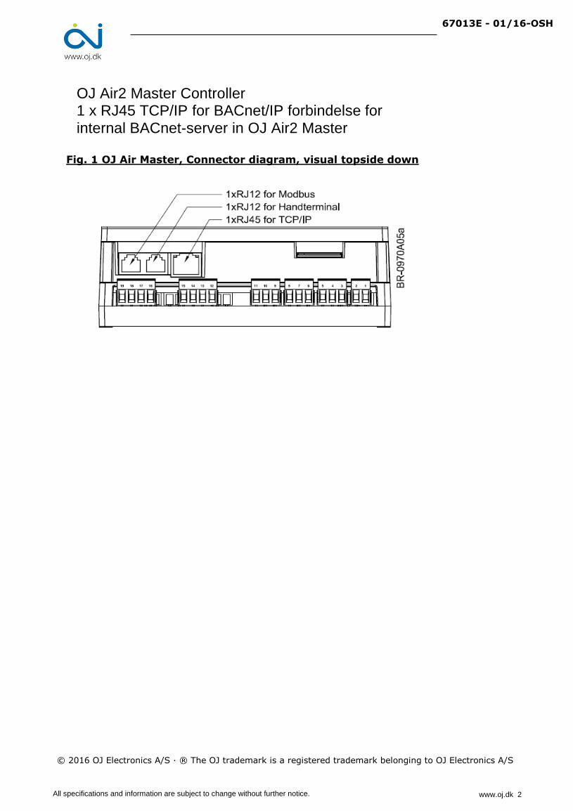
Fig. 1 OJ Air Master, Connector diagram, visual topside down
OJ Air2 Master Controller 1 x RJ45 TCP/IP for BACnet/IP forbindelse for internal BACnet-server in OJ Air2 Master
All specifications and information are subject to change without further notice. www.oj.dk 2
67013E - 01/16-OSH
BACnet
OJ Air2, Program version 3.25 and subsequent versions.
Overview
Air Handling Unit (AHU), which is equipped with an OJ-Air2Master controller.
The BACnet functionality is implemented in OJ-Air2Masters with software version 2.00 or higher.
The OJ-Air2Master is a BACnet Application Specific Controller (B-ASC)
Supported Data Link Layer Options: BACnet IP
Communication
BACnet TCP/IP: 1 pcs. 10/100Mbit Ethernet, RJ45 socket
Standard BACnet TCP/IP communication port: 47808
The Object_Identifier is automatic set to the last 5 digits in the OJ-Air2Master IP adress.
Samples: IP-adresse = 172.21.0.95 ………………..…….. Object Identifier = 95
IP-adresse = 155.37.0.216 ………………....... Object Identifier = 216
IP-adresse = 155.37.35.123 ………………..... Object Identifier = 35123
IP-adresse = 132.65.124.103 ……………….. Object Identifier = 24103
IP-adresse = 172.20.211.47 ………………..... Object Identifier = 11047
IP-adresse = 155.37.111.123 ………………... Object Identifier = 11123
IP-adresse = 168.25.111.1 ………………..….. Object Identifier = 11001
OBS! The Object_Identifier will only be set once and only when the OJ-Air2 Master is powered up or restarted
Max. 300 values can at the same time be registered to the COV (Change Of Value)
BACnet Interoperability Building Blocks Supported
Standard Object Types Supported
© 2016 OJ Electronics A/S · ® The Trade Mark OJ is an registered Trade Mark belonging to OJ Electronics A/S
Analog InputObject_Identifier, Object_Name, Object_Type, Present_Value, Status_Flags, Event_State, Out_Of_Service,
Units, Min_Pres_Value, Max_Pres_Value, Resolution, Reliability, COV_Increment
Device
Object_Identifier, Object_Name, Object_Type, System_Status, Vendor_Name, Vendor_Identifier,
Model_Name, Firmware_Revision, Aplication_Software_Version, Location, Description, Protocol_Version,
Protocol_Revision, Protocol_Services_Supported, Protocol_Object_Types_Supported, Object_list,
Max_APDU_Length_Accepted, Segmentation_Supported, APDU_Timeout, Number_Of_APDU_Retries,
Device_Address_Binding, Database_Revision.
Analog ValueObject_Identifier, Object_Name, Object_Type, Present_Value, Status_Flags, Event_State, Out_Of_Service,
Units, Priority_Array, Relinquish_Default, COV_Increment.
Binary InputObject_Identifier, Object_Name, Object_Type, Present_Value, Status_Flags, Event_State, Out_Of_Service,
Polarity.
Binary ValueObject_Identifier, Object_Name, Object_Type, Present_Value, Status_Flags, Event_State, Out_Of_Service,
Priority_Array, Relinquish_Default.
Device Management DM-DOB-B Device Management-Dynamic Object Binding-B
Device Management DM-DCC-B Device Management-Dynamic Communication Control-B
Object type Properties
Device Management
Data Sharing DS-RP-B Data Sharing-Read Property-B
Data sharing DS-WP-B Data Sharing-Write Property-B
DM-DDB-B
BACnet features enable BACnet control and monitoring of a complete
Device Management-Dynamic Device Binding-B
This protocol contains all BACnet addresses and registers in the OJ-Air2 Master. Updating of values in the individual
registers is dependent on the actual configuration of the air handling unit. It will, for example, be possible to read out
hydronic battery temperature Analog Input Object Instance 26 irrespective of whether or not an hydronic battery is
installed in the system concerned.
The value will, however, only be used if the associated temperature sensor is installed.
Object Indentifier:
Please also see the documents "OJ-Air2 BACnet PICS" (Protocol Implementation Conformance Statement)
and "OJ-Air2 EDE" (Engineering Data Exchange).
All specifications and information are subject to change without further notice. www.oj.dk 3
67013E - 01/16-OSH
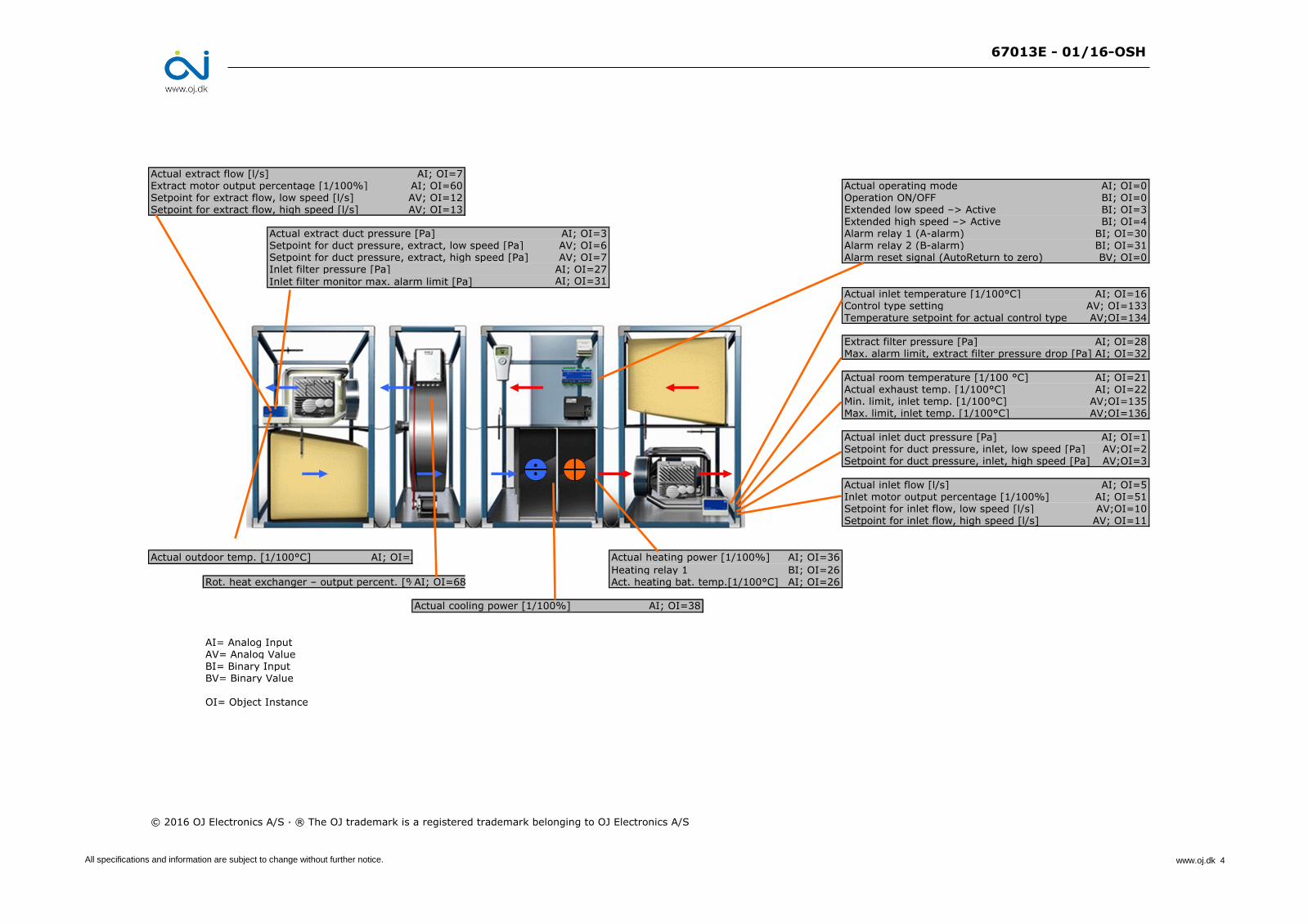
Actual extract flow [l/s] AI; OI=7Extract motor output percentage [1/100%] AI; OI=60 Actual operating mode AI; OI=0Setpoint for extract flow, low speed [l/s] AV; OI=12 Operation ON/OFF BI; OI=0Setpoint for extract flow, high speed [l/s] AV; OI=13 Extended low speed –> Active BI; OI=3
Extended high speed –> Active BI; OI=4Actual extract duct pressure [Pa] AI; OI=3 Alarm relay 1 (A-alarm) BI; OI=30Setpoint for duct pressure, extract, low speed [Pa] AV; OI=6 Alarm relay 2 (B-alarm) BI; OI=31Setpoint for duct pressure, extract, high speed [Pa] AV; OI=7 Alarm reset signal (AutoReturn to zero) BV; OI=0Inlet filter pressure [Pa] AI; OI=27
Inlet filter monitor max. alarm limit [Pa] AI; OI=31
Actual inlet temperature [1/100°C] AI; OI=16Control type setting AV; OI=133Temperature setpoint for actual control type AV;OI=134
Extract filter pressure [Pa] AI; OI=28Max. alarm limit, extract filter pressure drop [Pa] AI; OI=32
Actual room temperature [1/100 °C] AI; OI=21Actual exhaust temp. [1/100°C] AI; OI=22Min. limit, inlet temp. [1/100°C] AV;OI=135Max. limit, inlet temp. [1/100°C] AV;OI=136
Actual inlet duct pressure [Pa] AI; OI=1Setpoint for duct pressure, inlet, low speed [Pa] AV;OI=2Setpoint for duct pressure, inlet, high speed [Pa] AV;OI=3
Actual inlet flow [l/s] AI; OI=5Inlet motor output percentage [1/100%] AI; OI=51Setpoint for inlet flow, low speed [l/s] AV;OI=10Setpoint for inlet flow, high speed [l/s] AV; OI=11
Actual heating power [1/100%] AI; OI=36
Heating relay 1 BI; OI=26Rot. heat exchanger – output percent. [%]AI; OI=68 Act. heating bat. temp.[1/100°C] AI; OI=26
Actual cooling power [1/100%] AI; OI=38
AI= Analog InputAV= Analog ValueBI= Binary InputBV= Binary Value
OI= Object Instance
© 2016 OJ Electronics A/S · ® The OJ trademark is a registered trademark belonging to OJ Electronics A/S
Actual outdoor temp. [1/100°C] AI; OI=20
All specifications and information are subject to change without further notice. www.oj.dk 4
67013E - 01/16-OSH
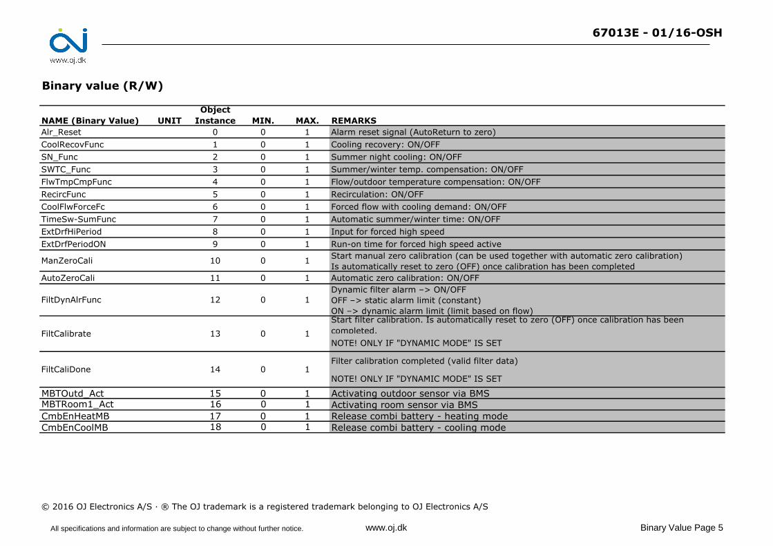
Binary value (R/W)
NAME (Binary Value) UNIT
Object
Instance MIN. MAX. REMARKS
Alr_Reset 0 0 1 Alarm reset signal (AutoReturn to zero)
CoolRecovFunc 1 0 1 Cooling recovery: ON/OFF
SN_Func 2 0 1 Summer night cooling: ON/OFF
SWTC_Func 3 0 1 Summer/winter temp. compensation: ON/OFF
FlwTmpCmpFunc 4 0 1 Flow/outdoor temperature compensation: ON/OFF
RecircFunc 5 0 1 Recirculation: ON/OFF
CoolFlwForceFc 6 0 1 Forced flow with cooling demand: ON/OFF
TimeSw-SumFunc 7 0 1 Automatic summer/winter time: ON/OFF
ExtDrfHiPeriod 8 0 1 Input for forced high speed
ExtDrfPeriodON 9 0 1 Run-on time for forced high speed active
Start manual zero calibration (can be used together with automatic zero calibration)
Is automatically reset to zero (OFF) once calibration has been completed
AutoZeroCali 11 0 1 Automatic zero calibration: ON/OFF
Dynamic filter alarm –> ON/OFF
OFF –> static alarm limit (constant)
ON –> dynamic alarm limit (limit based on flow)Start filter calibration. Is automatically reset to zero (OFF) once calibration has been
completed.
NOTE! ONLY IF "DYNAMIC MODE" IS SET
Filter calibration completed (valid filter data)
NOTE! ONLY IF "DYNAMIC MODE" IS SET
MBTOutd_Act 15 0 1 Activating outdoor sensor via BMSMBTRoom1_Act 16 0 1 Activating room sensor via BMS
CmbEnHeatMB 17 0 1 Release combi battery - heating mode
CmbEnCoolMB 18 0 1 Release combi battery - cooling mode
© 2016 OJ Electronics A/S · ® The OJ trademark is a registered trademark belonging to OJ Electronics A/S
FiltCaliDone 14
13
1
0 1
0 1
1
ManZeroCali 10
0
0
FiltDynAlrFunc 12
FiltCalibrate
All specifications and information are subject to change without further notice. www.oj.dk Binary Value Page 5
67013E - 01/16-OSH
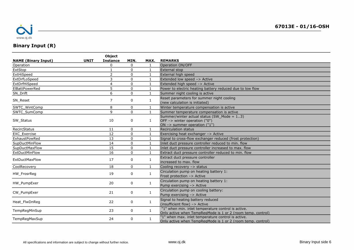
Binary Input (R)
NAME (Binary Input) UNIT
Object
Instance MIN. MAX. REMARKS
Operation 0 0 1 Operation ON/OFF
ExtStop 1 0 1 External stop
ExtHiSpeed 2 0 1 External high speed
ExtDrfLoSpeed 3 0 1 Extended low speed –> Active
ExtDrfHiSpeed 4 0 1 Extended high speed –> Active
ElBattPowerRed 5 0 1 Power to electric heating battery reduced due to low flow
SN_Drift 6 0 1 Summer night cooling is active
SN_Reset 7 0 1Reset parameters for summer night cooling
(new calculation is initiated)
SWTC_WintComp 8 0 1 Winter temperature compensation is active
SWTC_SumComp 9 0 1 Summer temperature compensation is active
Summer/winter actual status (SW_Mode = 1..3)OFF –> winter operation ("0")ON –> summer operation ("1")
RecircStatus 11 0 1 Recirculation status
EXC_Exercise 12 0 1 Exercising heat exchanger –> Active
ExhaustPowRed 13 0 1 Signal to cross-flow exchanger reduced (frost protection)
SupDuctMinFlow 14 0 1 Inlet duct pressure controller reduced to min. flow
SupDuctMaxFlow 15 0 1 Inlet duct pressure controller increased to max. flow
ExtDuctMinFlow 16 0 1 Extract duct pressure controller reduced to min. flow
ExtDuctMaxFlow 17 0 1Extract duct pressure controller
increased to max. flow
CoolRecovery 18 0 1 Cooling recovery –> status
HW_FrosrReg 19 0 1Circulation pump on heating battery 1:
Frost protection –> Active
HW_PumpExer 20 0 1Circulation pump on heating battery 1:
Pump exercising –> Active
CW_PumpExer 21 0 1Circulation pump on cooling battery:
Pump exercising –> Active
Heat_FlwDnReg 22 0 1Signal to heating battery reduced
(insufficient flow) –> Active
"1" when min. inlet temperature control is active. Only active when TempRegMode is 1 or 2 (room temp. control) "1" when max. inlet temperature control is active.Only active when TempRegMode is 1 or 2 (room temp. control)
TempRegMaxSup 24
1
23 0 1
SW_Status 10
0
0
1
TempRegMinSup
All specifications and information are subject to change without further notice. www.oj.dk Binary Input side 6
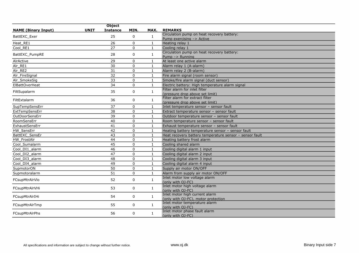
NAME (Binary Input) UNIT
Object
Instance MIN. MAX. REMARKS
BattEXC_Exer 25 0 1Circulation pump on heat recovery battery:
Pump exercising –> Active
Heat_RE1 26 0 1 Heating relay 1
Cool_RE1 27 0 1 Cooling relay 1
BattEXC_PumpRE 28 0 1Circulation pump on heat recovery battery:
Pump –> Running
AlrActive 29 0 1 At least one active alarm
Alr_RE1 30 0 1 Alarm relay 1 (A-alarm)
Alr_RE2 31 0 1 Alarm relay 2 (B-alarm)
Alr_FireSignal 32 0 1 Fire alarm signal (room sensor)
Alr_SmokeSig 33 0 1 Smoke/fire alarm signal (duct sensor)
ElBattOverHeat 34 0 1 Electric battery: High temperature alarm signal
FiltSupalarm 35 0 1Filter alarm for inlet filter
(pressure drop above set limit)
FiltExtalarm 36 0 1Filter alarm for extract filter
(pressure drop above set limit)
SupTempSensErr 37 0 1 Inlet temperature sensor – sensor fault
ExtTempSensErr 38 0 1 Extract temperature sensor – sensor fault
OutDoorSensErr 39 0 1 Outdoor temperature sensor – sensor fault
RoomSensErr 40 0 1 Room temperature sensor – sensor fault
ExhaustSensErr 41 0 1 Exhaust temperature sensor – sensor fault
HW_SensErr 42 0 1 Heating battery temperature sensor – sensor fault
BattEXC_SensEr 43 0 1 Heat recovery battery temperature sensor – sensor fault
HW_FrostAlr 44 0 1 Heating battery frost alarm
Cool_Sumalarm 45 0 1 Cooling shared alarm
Cool_DI1_alarm 46 0 1 Cooling digital alarm 1 input
Cool_DI2_alarm 47 0 1 Cooling digital alarm 2 input
Cool_DI3_alarm 48 0 1 Cooling digital alarm 3 input
Cool_DI4_alarm 49 0 1 Cooling digital alarm 4 input
SupmotorON 50 0 1 Supply air motor ON/OFF
Supmotoralarm 51 0 1 Alarm from supply air motor ON/OFF
FCsupMtrAlrVlo 52 0 1Inlet motor low voltage alarm
(only with OJ-FC)
FCsupMtrAlrVHi 53 0 1Inlet motor high voltage alarm
(only with OJ-FC)
FCsupMtrAlrIHi 54 0 1Inlet motor high current alarm
(only with OJ-FC), motor protection
FCsupMtrAlrTmp 55 0 1Inlet motor temperature alarm
(only with OJ-FC)
FCsupMtrAlrPhs 56 0 1Inlet motor phase fault alarm
(only with OJ-FC)
All specifications and information are subject to change without further notice. www.oj.dk Binary Input side 7
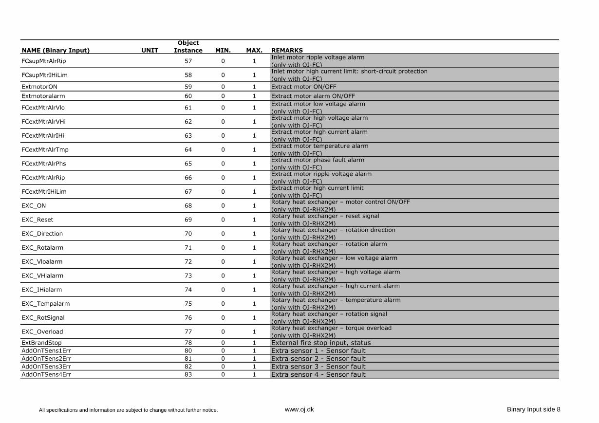
NAME (Binary Input) UNIT
Object
Instance MIN. MAX. REMARKS
FCsupMtrAlrRip 57 0 1Inlet motor ripple voltage alarm
(only with OJ-FC)
FCsupMtrIHiLim 58 0 1Inlet motor high current limit: short-circuit protection
(only with OJ-FC)
ExtmotorON 59 0 1 Extract motor ON/OFF
Extmotoralarm 60 0 1 Extract motor alarm ON/OFF
FCextMtrAlrVlo 61 0 1Extract motor low voltage alarm
(only with OJ-FC)
FCextMtrAlrVHi 62 0 1Extract motor high voltage alarm
(only with OJ-FC)
FCextMtrAlrIHi 63 0 1Extract motor high current alarm
(only with OJ-FC)
FCextMtrAlrTmp 64 0 1Extract motor temperature alarm
(only with OJ-FC)
FCextMtrAlrPhs 65 0 1Extract motor phase fault alarm
(only with OJ-FC)
FCextMtrAlrRip 66 0 1Extract motor ripple voltage alarm
(only with OJ-FC)
FCextMtrIHiLim 67 0 1Extract motor high current limit
(only with OJ-FC)
EXC_ON 68 0 1Rotary heat exchanger – motor control ON/OFF
(only with OJ-RHX2M)
EXC_Reset 69 0 1Rotary heat exchanger – reset signal
(only with OJ-RHX2M)
EXC_Direction 70 0 1Rotary heat exchanger – rotation direction
(only with OJ-RHX2M)
EXC_Rotalarm 71 0 1Rotary heat exchanger – rotation alarm
(only with OJ-RHX2M)
EXC_Vloalarm 72 0 1Rotary heat exchanger – low voltage alarm
(only with OJ-RHX2M)
EXC_VHialarm 73 0 1Rotary heat exchanger – high voltage alarm
(only with OJ-RHX2M)
EXC_IHialarm 74 0 1Rotary heat exchanger – high current alarm
(only with OJ-RHX2M)
EXC_Tempalarm 75 0 1Rotary heat exchanger – temperature alarm
(only with OJ-RHX2M)
EXC_RotSignal 76 0 1Rotary heat exchanger – rotation signal
(only with OJ-RHX2M)
EXC_Overload 77 0 1Rotary heat exchanger – torque overload
(only with OJ-RHX2M)
ExtBrandStop 78 0 1 External fire stop input, statusAddOnTSens1Err 80 0 1 Extra sensor 1 - Sensor faultAddOnTSens2Err 81 0 1 Extra sensor 2 - Sensor faultAddOnTSens3Err 82 0 1 Extra sensor 3 - Sensor faultAddOnTSens4Err 83 0 1 Extra sensor 4 - Sensor fault
All specifications and information are subject to change without further notice. www.oj.dk Binary Input side 8
NAME (Binary Input) UNIT
Object
Instance MIN. MAX. REMARKS
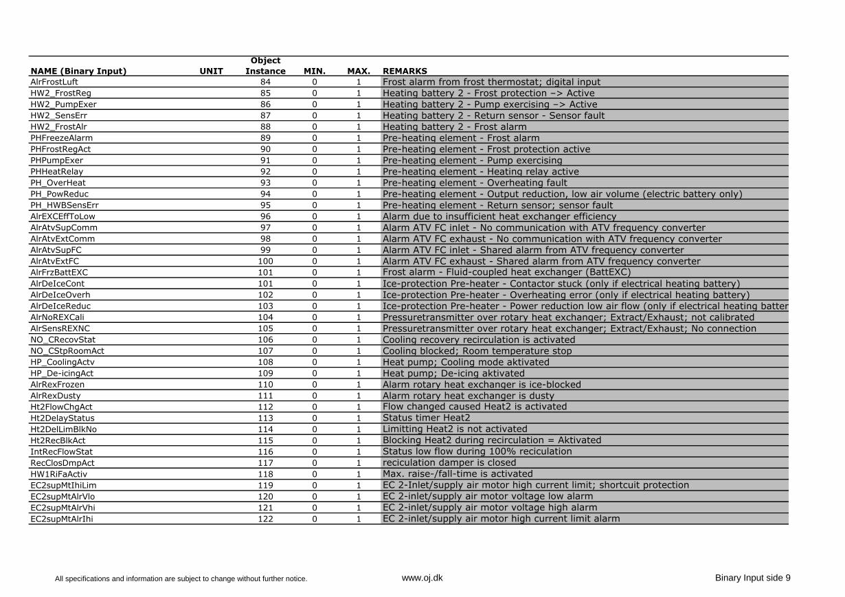
AlrFrostLuft 84 0 1 Frost alarm from frost thermostat; digital inputHW2_FrostReg 85 0 1 Heating battery 2 - Frost protection –> ActiveHW2_PumpExer 86 0 1 Heating battery 2 - Pump exercising –> ActiveHW2_SensErr 87 0 1 Heating battery 2 - Return sensor - Sensor faultHW2_FrostAlr 88 0 1 Heating battery 2 - Frost alarmPHFreezeAlarm 89 0 1 Pre-heating element - Frost alarmPHFrostRegAct 90 0 1 Pre-heating element - Frost protection activePHPumpExer 91 0 1 Pre-heating element - Pump exercisingPHHeatRelay 92 0 1 Pre-heating element - Heating relay activePH_OverHeat 93 0 1 Pre-heating element - Overheating faultPH_PowReduc 94 0 1 Pre-heating element - Output reduction, low air volume (electric battery only)PH_HWBSensErr 95 0 1 Pre-heating element - Return sensor; sensor faultAlrEXCEffToLow 96 0 1 Alarm due to insufficient heat exchanger efficiencyAlrAtvSupComm 97 0 1 Alarm ATV FC inlet - No communication with ATV frequency converterAlrAtvExtComm 98 0 1 Alarm ATV FC exhaust - No communication with ATV frequency converterAlrAtvSupFC 99 0 1 Alarm ATV FC inlet - Shared alarm from ATV frequency converterAlrAtvExtFC 100 0 1 Alarm ATV FC exhaust - Shared alarm from ATV frequency converterAlrFrzBattEXC 101 0 1 Frost alarm - Fluid-coupled heat exchanger (BattEXC)
AlrDeIceCont 101 0 1 Ice-protection Pre-heater - Contactor stuck (only if electrical heating battery)AlrDeIceOverh 102 0 1 Ice-protection Pre-heater - Overheating error (only if electrical heating battery)AlrDeIceReduc 103 0 1 Ice-protection Pre-heater - Power reduction low air flow (only if electrical heating battery)AlrNoREXCali 104 0 1 Pressuretransmitter over rotary heat exchanger; Extract/Exhaust; not calibratedAlrSensREXNC 105 0 1 Pressuretransmitter over rotary heat exchanger; Extract/Exhaust; No connectionNO_CRecovStat 106 0 1 Cooling recovery recirculation is activatedNO_CStpRoomAct 107 0 1 Cooling blocked; Room temperature stopHP_CoolingActv 108 0 1 Heat pump; Cooling mode aktivatedHP_De-icingAct 109 0 1 Heat pump; De-icing aktivatedAlrRexFrozen 110 0 1 Alarm rotary heat exchanger is ice-blockedAlrRexDusty 111 0 1 Alarm rotary heat exchanger is dustyHt2FlowChgAct 112 0 1 Flow changed caused Heat2 is activated
Ht2DelayStatus 113 0 1 Status timer Heat2
Ht2DelLimBlkNo 114 0 1 Limitting Heat2 is not activated
Ht2RecBlkAct 115 0 1 Blocking Heat2 during recirculation = Aktivated
IntRecFlowStat 116 0 1 Status low flow during 100% reciculation
RecClosDmpAct 117 0 1 reciculation damper is closed
HW1RiFaActiv 118 0 1 Max. raise-/fall-time is activated
EC2supMtIhiLim 119 0 1 EC 2-Inlet/supply air motor high current limit; shortcuit protection
EC2supMtAlrVlo 120 0 1 EC 2-inlet/supply air motor voltage low alarm
EC2supMtAlrVhi 121 0 1 EC 2-inlet/supply air motor voltage high alarm
EC2supMtAlrIhi 122 0 1 EC 2-inlet/supply air motor high current limit alarm
All specifications and information are subject to change without further notice. www.oj.dk Binary Input side 9
NAME (Binary Input) UNIT
Object
Instance MIN. MAX. REMARKS
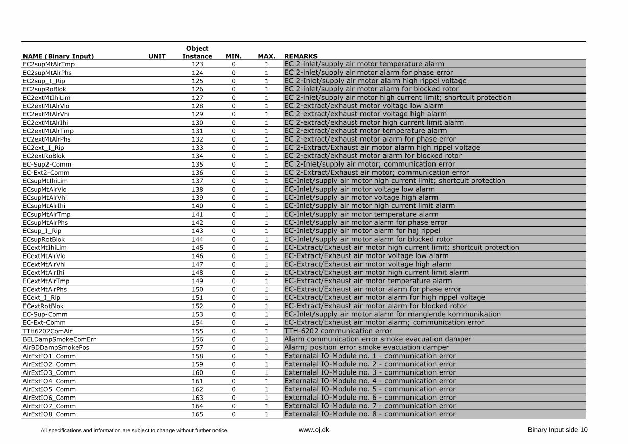
EC2supMtAlrTmp 123 0 1 EC 2-inlet/supply air motor temperature alarm
EC2supMtAlrPhs 124 0 1 EC 2-inlet/supply air motor alarm for phase error
EC2sup_I_Rip 125 0 1 EC 2-Inlet/supply air motor alarm high rippel voltage
EC2supRoBlok 126 0 1 EC 2-inlet/supply air motor alarm for blocked rotor
EC2extMtIhiLim 127 0 1 EC 2-inlet/supply air motor high current limit; shortcuit protection
EC2extMtAlrVlo 128 0 1 EC 2-extract/exhaust motor voltage low alarm
EC2extMtAlrVhi 129 0 1 EC 2-extract/exhaust motor voltage high alarm
EC2extMtAlrIhi 130 0 1 EC 2-extract/exhaust motor high current limit alarm
EC2extMtAlrTmp 131 0 1 EC 2-extract/exhaust motor temperature alarm
EC2extMtAlrPhs 132 0 1 EC 2-extract/exhaust motor alarm for phase error
EC2ext_I_Rip 133 0 1 EC 2-Extract/Exhaust air motor alarm high rippel voltage
EC2extRoBlok 134 0 1 EC 2-extract/exhaust motor alarm for blocked rotor
EC-Sup2-Comm 135 0 1 EC 2-Inlet/supply air motor; communication error
EC-Ext2-Comm 136 0 1 EC 2-Extract/Exhaust air motor; communication error
ECsupMtIhiLim 137 0 1 EC-Inlet/supply air motor high current limit; shortcuit protection
ECsupMtAlrVlo 138 0 1 EC-Inlet/supply air motor voltage low alarm
ECsupMtAlrVhi 139 0 1 EC-Inlet/supply air motor voltage high alarm
ECsupMtAlrIhi 140 0 1 EC-Inlet/supply air motor high current limit alarm
ECsupMtAlrTmp 141 0 1 EC-Inlet/supply air motor temperature alarm
ECsupMtAlrPhs 142 0 1 EC-Inlet/supply air motor alarm for phase error
ECsup_I_Rip 143 0 1 EC-Inlet/supply air motor alarm for høj rippel
ECsupRotBlok 144 0 1 EC-Inlet/supply air motor alarm for blocked rotor
ECextMtIhiLim 145 0 1 EC-Extract/Exhaust air motor high current limit; shortcuit protection
ECextMtAlrVlo 146 0 1 EC-Extract/Exhaust air motor voltage low alarm
ECextMtAlrVhi 147 0 1 EC-Extract/Exhaust air motor voltage high alarm
ECextMtAlrIhi 148 0 1 EC-Extract/Exhaust air motor high current limit alarm
ECextMtAlrTmp 149 0 1 EC-Extract/Exhaust air motor temperature alarm
ECextMtAlrPhs 150 0 1 EC-Extract/Exhaust air motor alarm for phase error
ECext_I_Rip 151 0 1 EC-Extract/Exhaust air motor alarm for high rippel voltage
ECextRotBlok 152 0 1 EC-Extract/Exhaust air motor alarm for blocked rotor
EC-Sup-Comm 153 0 1 EC-Inlet/supply air motor alarm for manglende kommunikation
EC-Ext-Comm 154 0 1 EC-Extract/Exhaust air motor alarm; communication error
TTH6202ComAlr 155 0 1 TTH-6202 communication error
BELDampSmokeComErr 156 0 1 Alarm communication error smoke evacuation damper
AlrBDDampSmokePos 157 0 1 Alarm; position error smoke evacuation damper
AlrExtIO1_Comm 158 0 1 Externalal IO-Module no. 1 - communication error
AlrExtIO2_Comm 159 0 1 Externalal IO-Module no. 2 - communication error
AlrExtIO3_Comm 160 0 1 Externalal IO-Module no. 3 - communication error
AlrExtIO4_Comm 161 0 1 Externalal IO-Module no. 4 - communication error
AlrExtIO5_Comm 162 0 1 Externalal IO-Module no. 5 - communication error
AlrExtIO6_Comm 163 0 1 Externalal IO-Module no. 6 - communication error
AlrExtIO7_Comm 164 0 1 Externalal IO-Module no. 7 - communication error
AlrExtIO8_Comm 165 0 1 Externalal IO-Module no. 8 - communication error
All specifications and information are subject to change without further notice. www.oj.dk Binary Input side 10
NAME (Binary Input) UNIT
Object
Instance MIN. MAX. REMARKS
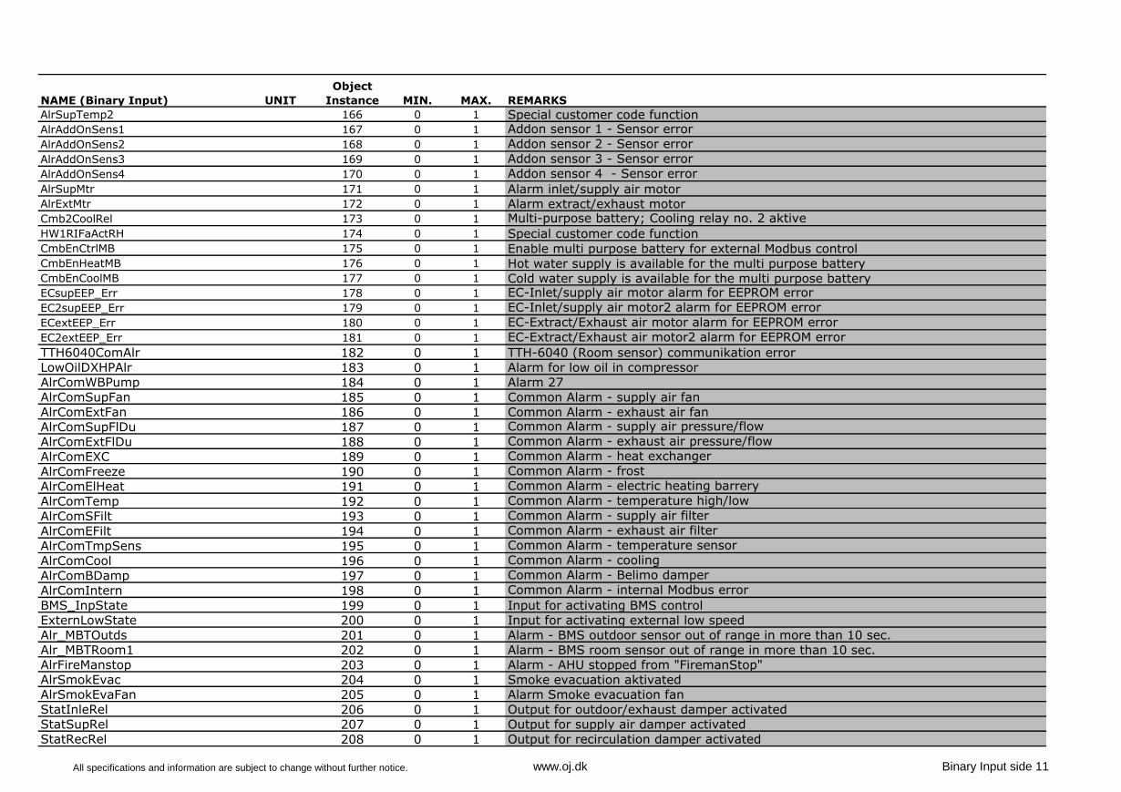
AlrSupTemp2 166 0 1 Special customer code functionAlrAddOnSens1 167 0 1 Addon sensor 1 - Sensor error
AlrAddOnSens2 168 0 1 Addon sensor 2 - Sensor error
AlrAddOnSens3 169 0 1 Addon sensor 3 - Sensor error
AlrAddOnSens4 170 0 1 Addon sensor 4 - Sensor error
AlrSupMtr 171 0 1 Alarm inlet/supply air motorAlrExtMtr 172 0 1 Alarm extract/exhaust motorCmb2CoolRel 173 0 1 Multi-purpose battery; Cooling relay no. 2 aktive
HW1RIFaActRH 174 0 1 Special customer code functionCmbEnCtrlMB 175 0 1 Enable multi purpose battery for external Modbus controlCmbEnHeatMB 176 0 1 Hot water supply is available for the multi purpose batteryCmbEnCoolMB 177 0 1 Cold water supply is available for the multi purpose batteryECsupEEP_Err 178 0 1 EC-Inlet/supply air motor alarm for EEPROM error
EC2supEEP_Err 179 0 1 EC-Inlet/supply air motor2 alarm for EEPROM error
ECextEEP_Err 180 0 1 EC-Extract/Exhaust air motor alarm for EEPROM error
EC2extEEP_Err 181 0 1 EC-Extract/Exhaust air motor2 alarm for EEPROM error
TTH6040ComAlr 182 0 1 TTH-6040 (Room sensor) communikation error
LowOilDXHPAlr 183 0 1 Alarm for low oil in compressor
AlrComWBPump 184 0 1 Alarm 27
AlrComSupFan 185 0 1 Common Alarm - supply air fan
AlrComExtFan 186 0 1 Common Alarm - exhaust air fan
AlrComSupFlDu 187 0 1 Common Alarm - supply air pressure/flow
AlrComExtFlDu 188 0 1 Common Alarm - exhaust air pressure/flow
AlrComEXC 189 0 1 Common Alarm - heat exchanger
AlrComFreeze 190 0 1 Common Alarm - frost
AlrComElHeat 191 0 1 Common Alarm - electric heating barrery
AlrComTemp 192 0 1 Common Alarm - temperature high/low
AlrComSFilt 193 0 1 Common Alarm - supply air filter
AlrComEFilt 194 0 1 Common Alarm - exhaust air filter
AlrComTmpSens 195 0 1 Common Alarm - temperature sensor
AlrComCool 196 0 1 Common Alarm - cooling
AlrComBDamp 197 0 1 Common Alarm - Belimo damper
AlrComIntern 198 0 1 Common Alarm - internal Modbus error
BMS_InpState 199 0 1 Input for activating BMS control
ExternLowState 200 0 1 Input for activating external low speed
Alr_MBTOutds 201 0 1 Alarm - BMS outdoor sensor out of range in more than 10 sec.
Alr_MBTRoom1 202 0 1 Alarm - BMS room sensor out of range in more than 10 sec.
AlrFireManstop 203 0 1 Alarm - AHU stopped from "FiremanStop"
AlrSmokEvac 204 0 1 Smoke evacuation aktivated
AlrSmokEvaFan 205 0 1 Alarm Smoke evacuation fan
StatInleRel 206 0 1 Output for outdoor/exhaust damper activated
StatSupRel 207 0 1 Output for supply air damper activated
StatRecRel 208 0 1 Output for recirculation damper activated
All specifications and information are subject to change without further notice. www.oj.dk Binary Input side 11
NAVN (Binary Input) ENHED
Object
Instance MIN MAX BEMÆRKNINGER
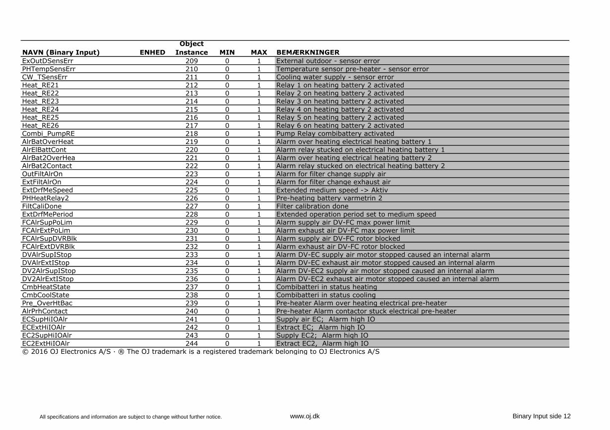
ExOutDSensErr 209 0 1 External outdoor - sensor error
PHTempSensErr 210 0 1 Temperature sensor pre-heater - sensor error
CW_TSensErr 211 0 1 Cooling water supply - sensor error
Heat_RE21 212 0 1 Relay 1 on heating battery 2 activated
Heat_RE22 213 0 1 Relay 2 on heating battery 2 activated
Heat_RE23 214 0 1 Relay 3 on heating battery 2 activated
Heat_RE24 215 0 1 Relay 4 on heating battery 2 activated
Heat_RE25 216 0 1 Relay 5 on heating battery 2 activated
Heat_RE26 217 0 1 Relay 6 on heating battery 2 activated
Combi_PumpRE 218 0 1 Pump Relay combibattery activated
AlrBatOverHeat 219 0 1 Alarm over heating electrical heating battery 1
AlrElBattCont 220 0 1 Alarm relay stucked on electrical heating battery 1
AlrBat2OverHea 221 0 1 Alarm over heating electrical heating battery 2
AlrBat2Contact 222 0 1 Alarm relay stucked on electrical heating battery 2
OutFiltAlrOn 223 0 1 Alarm for filter change supply air
ExtFiltAlrOn 224 0 1 Alarm for filter change exhaust air
ExtDrfMeSpeed 225 0 1 Extended medium speed -> AktivPHHeatRelay2 226 0 1 Pre-heating battery varmetrin 2
FiltCaliDone 227 0 1 Filter calibration done
ExtDrfMePeriod 228 0 1 Extended operation period set to medium speed
FCAlrSupPoLim 229 0 1 Alarm supply air DV-FC max power limit
FCAlrExtPoLim 230 0 1 Alarm exhaust air DV-FC max power limit
FCAlrSupDVRBlk 231 0 1 Alarm supply air DV-FC rotor blocked
FCAlrExtDVRBlk 232 0 1 Alarm exhaust air DV-FC rotor blocked
DVAlrSupIStop 233 0 1 Alarm DV-EC supply air motor stopped caused an internal alarm
DVAlrExtIStop 234 0 1 Alarm DV-EC exhaust air motor stopped caused an internal alarm
DV2AlrSupIStop 235 0 1 Alarm DV-EC2 supply air motor stopped caused an internal alarm
DV2AlrExtIStop 236 0 1 Alarm DV-EC2 exhaust air motor stopped caused an internal alarm
CmbHeatState 237 0 1 Combibatteri in status heating
CmbCoolState 238 0 1 Combibatteri in status cooling
Pre_OverHtBac 239 0 1 Pre-heater Alarm over heating electrical pre-heater
AlrPrhContact 240 0 1 Pre-heater Alarm contactor stuck electrical pre-heater
ECSupHiIOAlr 241 0 1 Supply air EC; Alarm high IO
ECExtHiIOAlr 242 0 1 Extract EC; Alarm high IO
EC2SupHiIOAlr 243 0 1 Supply EC2; Alarm high IO
EC2ExtHiIOAlr 244 0 1 Extract EC2, Alarm high IO
© 2016 OJ Electronics A/S · ® The OJ trademark is a registered trademark belonging to OJ Electronics A/S
All specifications and information are subject to change without further notice. www.oj.dk Binary Input side 12
67013E - 01/16-OSH
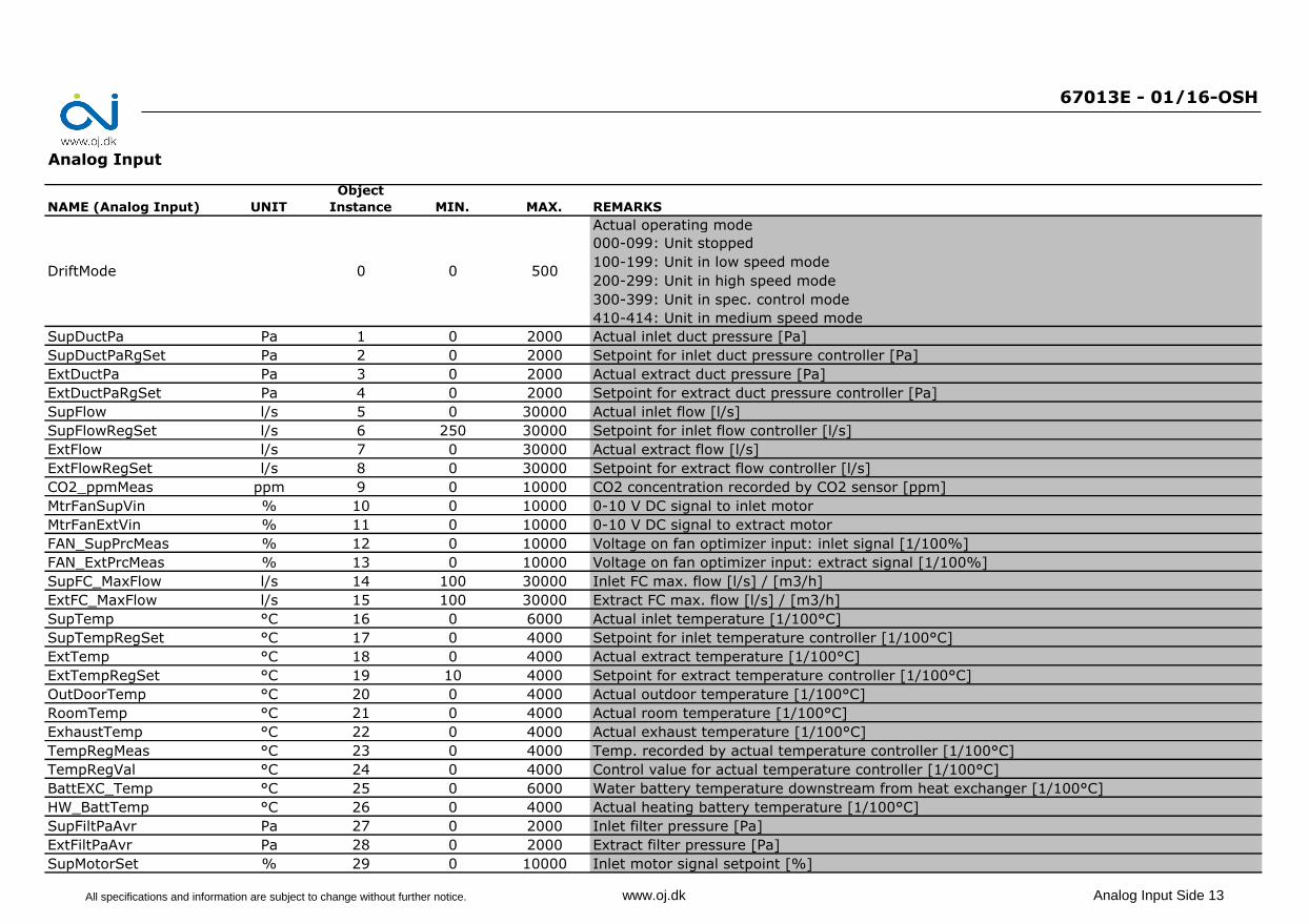
Analog Input
NAME (Analog Input) UNIT
Object
Instance MIN. MAX. REMARKS
Actual operating mode
000-099: Unit stopped
100-199: Unit in low speed mode
200-299: Unit in high speed mode
300-399: Unit in spec. control mode
410-414: Unit in medium speed mode
SupDuctPa Pa 1 0 2000 Actual inlet duct pressure [Pa]
SupDuctPaRgSet Pa 2 0 2000 Setpoint for inlet duct pressure controller [Pa]
ExtDuctPa Pa 3 0 2000 Actual extract duct pressure [Pa]
ExtDuctPaRgSet Pa 4 0 2000 Setpoint for extract duct pressure controller [Pa]
SupFlow l/s 5 0 30000 Actual inlet flow [l/s]
SupFlowRegSet l/s 6 250 30000 Setpoint for inlet flow controller [l/s]
ExtFlow l/s 7 0 30000 Actual extract flow [l/s]
ExtFlowRegSet l/s 8 0 30000 Setpoint for extract flow controller [l/s]
CO2_ppmMeas ppm 9 0 10000 CO2 concentration recorded by CO2 sensor [ppm]
MtrFanSupVin % 10 0 10000 0-10 V DC signal to inlet motor
MtrFanExtVin % 11 0 10000 0-10 V DC signal to extract motor
FAN_SupPrcMeas % 12 0 10000 Voltage on fan optimizer input: inlet signal [1/100%]
FAN_ExtPrcMeas % 13 0 10000 Voltage on fan optimizer input: extract signal [1/100%]
SupFC_MaxFlow l/s 14 100 30000 Inlet FC max. flow [l/s] / [m3/h]
ExtFC_MaxFlow l/s 15 100 30000 Extract FC max. flow [l/s] / [m3/h]
SupTemp °C 16 0 6000 Actual inlet temperature [1/100°C]
SupTempRegSet °C 17 0 4000 Setpoint for inlet temperature controller [1/100°C]
ExtTemp °C 18 0 4000 Actual extract temperature [1/100°C]
ExtTempRegSet °C 19 10 4000 Setpoint for extract temperature controller [1/100°C]
OutDoorTemp °C 20 0 4000 Actual outdoor temperature [1/100°C]
RoomTemp °C 21 0 4000 Actual room temperature [1/100°C]
ExhaustTemp °C 22 0 4000 Actual exhaust temperature [1/100°C]
TempRegMeas °C 23 0 4000 Temp. recorded by actual temperature controller [1/100°C]
TempRegVal °C 24 0 4000 Control value for actual temperature controller [1/100°C]
BattEXC_Temp °C 25 0 6000 Water battery temperature downstream from heat exchanger [1/100°C]
HW_BattTemp °C 26 0 4000 Actual heating battery temperature [1/100°C]
SupFiltPaAvr Pa 27 0 2000 Inlet filter pressure [Pa]
ExtFiltPaAvr Pa 28 0 2000 Extract filter pressure [Pa]
SupMotorSet % 29 0 10000 Inlet motor signal setpoint [%]
DriftMode 0 0 500
All specifications and information are subject to change without further notice. www.oj.dk Analog Input Side 13
NAME (Analog Input) UNIT
Object
Instance MIN. MAX. REMARKS
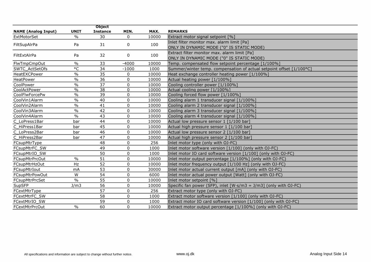
ExtMotorSet % 30 0 10000 Extract motor signal setpoint [%]
Inlet filter monitor max. alarm limit [Pa]
ONLY IN DYNAMIC MODE ("0" IS STATIC MODE)
Extract filter monitor max. alarm limit [Pa]
ONLY IN DYNAMIC MODE ("0" IS STATIC MODE)
FlwTmpCmpOut % 33 -4000 10000 Temp. compensated flow setpoint percentage [1/100%]
SWTC_ActSetOfs °C 34 -1000 1000 Summer/winter temp. compensation of actual setpoint offset [1/100°C]
HeatEXCPower % 35 0 10000 Heat exchange controller heating power [1/100%]
HeatPower % 36 0 10000 Actual heating power [1/100%]
CoolPower % 37 0 10000 Cooling controller power [1/100%]
CoolActPower % 38 0 10000 Actual cooling power [1/100%]
CoolFlwForcePw % 39 0 10000 Cooling forced flow power [1/100%]
CoolVin1Alarm % 40 0 10000 Cooling alarm 1 transducer signal [1/100%]
CoolVin2Alarm % 41 0 10000 Cooling alarm 2 transducer signal [1/100%]
CoolVin3Alarm % 42 0 10000 Cooling alarm 3 transducer signal [1/100%]
CoolVin4Alarm % 43 0 10000 Cooling alarm 4 transducer signal [1/100%]
C_LoPress1Bar bar 44 0 10000 Actual low pressure sensor 1 [1/100 bar]
C_HiPress1Bar bar 45 0 10000 Actual high pressure sensor 1 [1/100 bar]
C_LoPress2Bar bar 46 0 10000 Actual low pressure sensor 2 [1/100 bar]
C_HiPress2Bar bar 47 0 10000 Actual high pressure sensor 2 [1/100 bar]
FCsupMtrType 48 0 256 Inlet motor type (only with OJ-FC)
FCsupMtrFC_SW 49 0 1000 Inlet motor software version [1/100] (only with OJ-FC)
FCsupMtrIO_SW 50 0 1000 Inlet motor IO card software version [1/100] (only with OJ-FC)
FCsupMtrPrcOut % 51 0 10000 Inlet motor output percentage [1/100%] (only with OJ-FC)
FCsupMtrHzOut Hz 52 0 10000 Inlet motor frequency output [1/100 Hz] (only with OJ-FC)
FCsupMtrIout mA 53 0 30000 Inlet motor actual current output [mA] (only with OJ-FC)
FCsupMtrPowOut W 54 0 6000 Inlet motor actual power output [Watt] (only with OJ-FC)
FCsupMtrPrcSet % 55 0 10000 Inlet motor setpoint [%]
SupSFP J/m3 56 0 10000 Specific fan power (SFP), inlet [W·s/m3 = J/m3] (only with OJ-FC)
FCextMtrType 57 0 256 Extract motor type (only with OJ-FC)
FCextMtrFC_SW 58 0 1000 Extract motor software version [1/100] (only with OJ-FC)
FCextMtrIO_SW 59 0 1000 Extract motor IO card software version [1/100] (only with OJ-FC)
FCextMtrPrcOut % 60 0 10000 Extract motor output percentage [1/100%] (only with OJ-FC)
Pa 31
FiltExtAlrPa Pa 32
FiltSupAlrPa
0 100
0 100
All specifications and information are subject to change without further notice. www.oj.dk Analog Input Side 14
NAME (Analog Input) UNIT
Object
Instance MIN. MAX. REMARKS
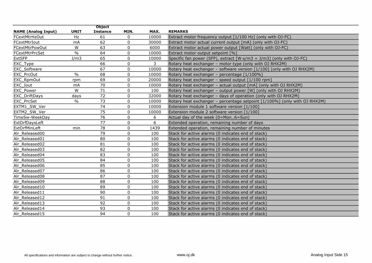
FCextMtrHzOut Hz 61 0 10000 Extract motor frequency output [1/100 Hz] (only with OJ-FC)
FCextMtrIout mA 62 0 30000 Extract motor actual current output [mA] (only with OJ-FC)
FCextMtrPowOut W 63 0 6000 Extract motor actual power output [Watt] (only with OJ-FC)
FCextMtrPrcSet % 64 0 10000 Extract motor output setpoint [%]
ExtSFP J/m3 65 0 10000 Specific fan power (SFP), extract [W·s/m3 = J/m3] (only with OJ-FC)
EXC_Type 66 0 3 Rotary heat exchanger – motor type (only with OJ RHX2M)
EXC_Software 67 0 10000 Rotary heat exchanger – software version [1/100] (only with OJ RHX2M)
EXC_PrcOut % 68 0 10000 Rotary heat exchanger – percentage [1/100%]
EXC_RpmOut rpm 69 0 20000 Rotary heat exchanger – speed output [1/100 rpm]
EXC_Iout mA 70 0 10000 Rotary heat exchanger – actual output [mA] (only with OJ RHX2M)
EXC_Power W 71 0 100 Rotary heat exchanger – output power [W] (only with OJ RHX2M)
EXC_DriftDays days 72 0 32000 Rotary heat exchanger – days of operation (only with OJ RHX2M)
EXC_PrcSet % 73 0 10000 Rotary heat exchanger – percentage setpoint [1/100%] (only with OJ RHX2M)
EXTM1_SW_Ver 74 0 10000 Extension module 1 software version [1/100]
EXTM2_SW_Ver 75 0 10000 Extension module 2 software version [1/100]
TimeSw-WeekDay 76 0 6 Actual day of the week (0=Mon..6=Sun)
ExtDrfDaysLeft 77 0 6 Extended operation, remaining number of days
ExtDrfMinLeft min 78 0 1439 Extended operation, remaining number of minutes
Alr_Released00 79 0 100 Stack for active alarms (0 indicates end of stack)
Alr_Released01 80 0 100 Stack for active alarms (0 indicates end of stack)
Alr_Released02 81 0 100 Stack for active alarms (0 indicates end of stack)
Alr_Released03 82 0 100 Stack for active alarms (0 indicates end of stack)
Alr_Released04 83 0 100 Stack for active alarms (0 indicates end of stack)
Alr_Released05 84 0 100 Stack for active alarms (0 indicates end of stack)
Alr_Released06 85 0 100 Stack for active alarms (0 indicates end of stack)
Alr_Released07 86 0 100 Stack for active alarms (0 indicates end of stack)
Alr_Released08 87 0 100 Stack for active alarms (0 indicates end of stack)
Alr_Released09 88 0 100 Stack for active alarms (0 indicates end of stack)
Alr_Released10 89 0 100 Stack for active alarms (0 indicates end of stack)
Alr_Released11 90 0 100 Stack for active alarms (0 indicates end of stack)
Alr_Released12 91 0 100 Stack for active alarms (0 indicates end of stack)
Alr_Released13 92 0 100 Stack for active alarms (0 indicates end of stack)
Alr_Released14 93 0 100 Stack for active alarms (0 indicates end of stack)
Alr_Released15 94 0 100 Stack for active alarms (0 indicates end of stack)
All specifications and information are subject to change without further notice. www.oj.dk Analog Input Side 15
NAME (Analog Input) UNIT
Object
Instance MIN. MAX. REMARKS
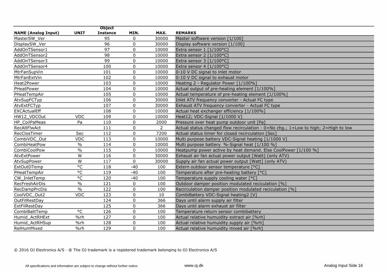
MasterSW_Ver 95 0 30000 Master software version [1/100]
DisplaySW_Ver 96 0 30000 Display software version [1/100]
AddOnTSensor1 97 0 10000 Extra sensor 1 [1/100°C]
AddOnTSensor2 98 0 10000 Extra sensor 2 [1/100°C]
AddOnTSensor3 99 0 10000 Extra sensor 3 [1/100°C]
AddOnTSensor4 100 0 10000 Extra sensor 4 [1/100°C]
MtrFanSupVin 101 0 10000 0-10 V DC signal to inlet motor
MtrFanExtVin 102 0 10000 0-10 V DC signal to exhaust motor
Heat2Power 103 0 10000 Heating 2 - Regulator Power [1/100%]
PHeatPower 104 0 10000 Actual output of pre-heating element [1/100%]
PHeatTempAir 105 0 10000 Actual temperature of pre-heating element [1/100%]
AtvSupFCTyp 106 0 30000 Inlet ATV frequency converter - Actual FC type
AtvExtFCTyp 107 0 30000 Exhaust ATV frequency converter - Actual FC type
EXCActualEff 108 0 10000 Actual heat exchanger efficiency [1/100%]
HW12_VDCOut VDC 109 0 10000 Heat12; VDC-Signal [1/1000 V]
HP_CoilPaMeas Pa 110 0 2000 Pressure over heat pump outdoor unit [Pa]
RecAltFlwAct 111 0 2 Actual status changed flow recirculation - 0=No chg.; 1=Low to high; 2=High to low
RecClosTimer Sec 112 0 7200 Actual status timer for closed recirculation [Sec]
CombiVDC_Out VDC 113 0 10000 Multi purpose battery VDC-Signal heating [1/1000 V]
CombiHeatPow % 114 0 10000 Multi purpose battery %-Signal heat [1/100 %]
CombiCoolPow % 115 0 10000 Heatpump power active by heat demand. Else CoolPower [1/100 %]
AtvExtPower W 116 0 30000 Exhaust air fan actual power output [Watt] (only ATV)
AtvSupPower W 117 0 30000 Supply air fan actual power output [Watt] (only ATV)
ExtOutDTemp °C 118 -40 100 Extern outdoor sensor temperature [°C]
PHeatTempAir °C 119 -40 100 Temperature after pre-heating battery [°C]
CW_InletTemp °C 120 -40 100 Temperature supply cooling water [°C]
RecFreshAirDis % 121 0 100 Outdoor damper position modulated reciculation [%]
RecDampPrcDis % 122 0 100 Recirculation damper position modulated reciculation [%]
CoolVDC_Out2 VDC 123 0 10 CombiBattery VDC-Signal heating2 [V]
OutFilRestDay 124 0 366 Days until alarm supply air filter
ExtFilRestDay 125 0 366 Days until alarm exhaust air filter
CombiBattTemp °C 126 0 100 Temperature return sensor combibattery
Humid_ActRHExt %rh 127 0 100 Actual relative humuidity extract air [%rh]
Humid_ActRHSup %rh 128 0 100 Actual relative humuidity supply air [%rh]
RelHumMixed %rh 129 0 100 Actual relative humuidity mixed air [%rh]
© 2016 OJ Electronics A/S · ® The OJ trademark is a registered trademark belonging to OJ Electronics A/S
All specifications and information are subject to change without further notice. www.oj.dk Analog Input Side 16
67013E - 01/16-OSH
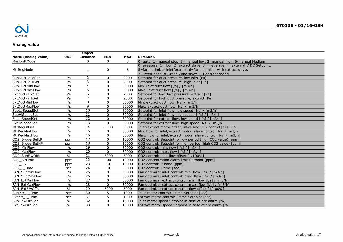
Analog value
NAME (Analog Value) UNIT
Object
Instance MIN MAX REMARKS
ManDriftMode 0 0 3 0=auto, 1=manual stop, 3=manual low, 3=manual high, 6-manual Medium
MtrRegMode 1 0 6
0=pressure, 1=flow, 2=extract slave, 3=inlet slave, 4=external V DC Setpoint,
5=fan optimizer inlet/extract, 6=fan optimizer with extract slave,
7-Green Zone, 8-Green Zone slave, 9-Constant speedSupDuctPaLoSet Pa 2 0 2000 Setpoint for duct pressure, low inlet [Pa]
SupDuctPaHiSet Pa 3 0 2000 Setpoint for duct pressure, high inlet [Pa]
SupDuctMinFlow l/s 4 0 30000 Min. inlet duct flow [l/s] / [m3/h]
SupDuctMaxFlow l/s 5 0 30000 Max. inlet duct flow [l/s] / [m3/h]
ExtDuctPaLoSet Pa 6 0 2000 Setpoint for low duct pressure, extract [Pa]
ExtDuctPaHiSet Pa 7 0 2000 Setpoint for high duct pressure, extract [Pa]
ExtDuctMinFlow l/s 8 0 30000 Min. extract duct flow [l/s] / [m3/h]
ExtDuctMaxFlow l/s 9 0 30000 Max. extract duct flow [l/s] / [m3/h]
SupLoSpeedSet l/s 10 0 30000 Setpoint for inlet flow, low speed [l/s] / [m3/h]
SupHiSpeedSet l/s 11 0 30000 Setpoint for inlet flow, high speed [l/s] / [m3/h]
ExtLoSpeedSet l/s 12 0 30000 Setpoint for extract flow, low speed [l/s] / [m3/h]
ExtHiSpeedSet l/s 13 0 30000 Setpoint for extract flow, high speed [l/s] / [m3/h]
MtrRegOffset % 14 -5000 5000 Inlet/extract motor offset, slave and CO2 control [1/100%]
MtrRegMinFlow l/s 15 0 30000 Min. flow for inlet/extract motor, slave control [l/s] / [m3/h]
MtrRegMaxFlow l/s 16 0 30000 Max. flow for inlet/extract motor, slave control [l/s] / [m3/h]
CO2_BrugerSetLP ppm 17 0 10000 CO2 control: Setpoint for low period (high CO2 value) [ppm]
CO2_BrugerSetHP ppm 18 0 10000 CO2 control: Setpoint for high period (high CO2 value) [ppm]
CO2_MinFlow l/s 19 0 30000 CO2 control: min. flow [l/s] / [m3/h]
CO2_MaxFlow l/s 20 0 30000 CO2 control: max. flow [l/s] / [m3/h]
CO2_SupFlwOffs % 21 -5000 5000 CO2 control: inlet flow offset [1/100%]
CO2_AlrLimit ppm 22 100 10000 CO2 concentration alarm limit Setpoint [ppm]
CO2_PB ppm 23 10 10000 CO2 control: P-band [ppm]
CO2_I_Time sec 24 10 30000 CO2 control: I-time [sec]
FAN_SupMinFlow l/s 25 0 30000 Fan optimizer inlet control: min. flow [l/s] / [m3/h]
FAN_SupMaxFlow l/s 26 0 30000 Fan optimizer inlet control: max. flow [l/s] / [m3/h]
FAN_ExtMinFlow l/s 27 0 30000 Fan optimizer extract control: min. flow [l/s] / [m3/h]
FAN_ExtMaxFlow l/s 28 0 30000 Fan optimizer extract control: max. flow [l/s] / [m3/h]
FAN_ExtFlwOffs % 29 -5000 5000 Fan optimizer extract control: flow offset [1/100%]
SupMtr_I_Time sec 30 5 1000 Inlet motor control: I-time Setpoint [sec]
ExtMtr_I_Time sec 31 5 1000 Extract motor control: I-time Setpoint [sec]
SupFlowFireSet % 32 0 10000 Inlet motor speed Setpoint in case of fire alarm [%]
ExtFlowFireSet % 33 0 10000 Extract motor speed Setpoint in case of fire alarm [%]
All specifications and information are subject to change without further notice. www.oj.dk Analog value 17
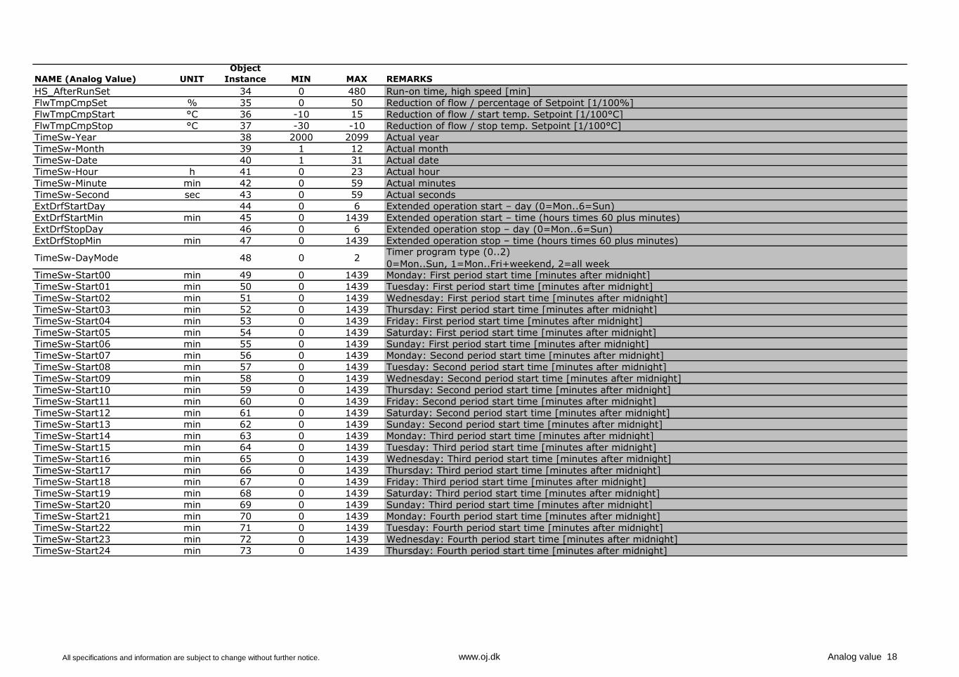
NAME (Analog Value) UNIT
Object
Instance MIN MAX REMARKS
HS_AfterRunSet 34 0 480 Run-on time, high speed [min]
FlwTmpCmpSet % 35 0 50 Reduction of flow / percentage of Setpoint [1/100%]
FlwTmpCmpStart °C 36 -10 15 Reduction of flow / start temp. Setpoint [1/100°C]
FlwTmpCmpStop °C 37 -30 -10 Reduction of flow / stop temp. Setpoint [1/100°C]
TimeSw-Year 38 2000 2099 Actual year
TimeSw-Month 39 1 12 Actual month
TimeSw-Date 40 1 31 Actual date
TimeSw-Hour h 41 0 23 Actual hour
TimeSw-Minute min 42 0 59 Actual minutes
TimeSw-Second sec 43 0 59 Actual seconds
ExtDrfStartDay 44 0 6 Extended operation start – day (0=Mon..6=Sun)
ExtDrfStartMin min 45 0 1439 Extended operation start – time (hours times 60 plus minutes)
ExtDrfStopDay 46 0 6 Extended operation stop – day (0=Mon..6=Sun)
ExtDrfStopMin min 47 0 1439 Extended operation stop – time (hours times 60 plus minutes)
TimeSw-DayMode 48 0 2Timer program type (0..2)
0=Mon..Sun, 1=Mon..Fri+weekend, 2=all weekTimeSw-Start00 min 49 0 1439 Monday: First period start time [minutes after midnight]
TimeSw-Start01 min 50 0 1439 Tuesday: First period start time [minutes after midnight]
TimeSw-Start02 min 51 0 1439 Wednesday: First period start time [minutes after midnight]
TimeSw-Start03 min 52 0 1439 Thursday: First period start time [minutes after midnight]
TimeSw-Start04 min 53 0 1439 Friday: First period start time [minutes after midnight]
TimeSw-Start05 min 54 0 1439 Saturday: First period start time [minutes after midnight]
TimeSw-Start06 min 55 0 1439 Sunday: First period start time [minutes after midnight]
TimeSw-Start07 min 56 0 1439 Monday: Second period start time [minutes after midnight]
TimeSw-Start08 min 57 0 1439 Tuesday: Second period start time [minutes after midnight]
TimeSw-Start09 min 58 0 1439 Wednesday: Second period start time [minutes after midnight]
TimeSw-Start10 min 59 0 1439 Thursday: Second period start time [minutes after midnight]
TimeSw-Start11 min 60 0 1439 Friday: Second period start time [minutes after midnight]
TimeSw-Start12 min 61 0 1439 Saturday: Second period start time [minutes after midnight]
TimeSw-Start13 min 62 0 1439 Sunday: Second period start time [minutes after midnight]
TimeSw-Start14 min 63 0 1439 Monday: Third period start time [minutes after midnight]
TimeSw-Start15 min 64 0 1439 Tuesday: Third period start time [minutes after midnight]
TimeSw-Start16 min 65 0 1439 Wednesday: Third period start time [minutes after midnight]
TimeSw-Start17 min 66 0 1439 Thursday: Third period start time [minutes after midnight]
TimeSw-Start18 min 67 0 1439 Friday: Third period start time [minutes after midnight]
TimeSw-Start19 min 68 0 1439 Saturday: Third period start time [minutes after midnight]
TimeSw-Start20 min 69 0 1439 Sunday: Third period start time [minutes after midnight]
TimeSw-Start21 min 70 0 1439 Monday: Fourth period start time [minutes after midnight]
TimeSw-Start22 min 71 0 1439 Tuesday: Fourth period start time [minutes after midnight]
TimeSw-Start23 min 72 0 1439 Wednesday: Fourth period start time [minutes after midnight]
TimeSw-Start24 min 73 0 1439 Thursday: Fourth period start time [minutes after midnight]
All specifications and information are subject to change without further notice. www.oj.dk Analog value 18
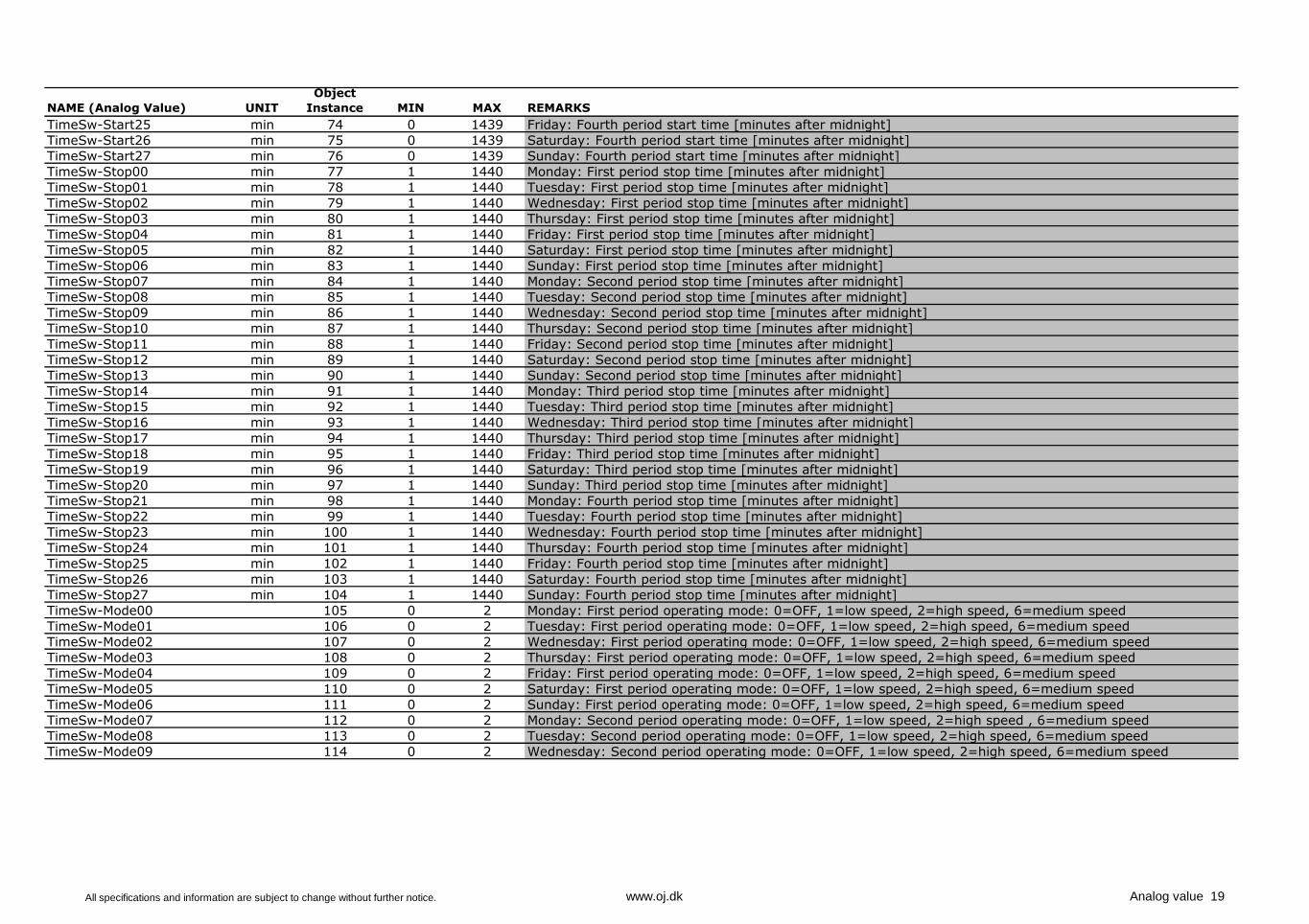
NAME (Analog Value) UNIT
Object
Instance MIN MAX REMARKS
TimeSw-Start25 min 74 0 1439 Friday: Fourth period start time [minutes after midnight]
TimeSw-Start26 min 75 0 1439 Saturday: Fourth period start time [minutes after midnight]
TimeSw-Start27 min 76 0 1439 Sunday: Fourth period start time [minutes after midnight]
TimeSw-Stop00 min 77 1 1440 Monday: First period stop time [minutes after midnight]
TimeSw-Stop01 min 78 1 1440 Tuesday: First period stop time [minutes after midnight]
TimeSw-Stop02 min 79 1 1440 Wednesday: First period stop time [minutes after midnight]
TimeSw-Stop03 min 80 1 1440 Thursday: First period stop time [minutes after midnight]
TimeSw-Stop04 min 81 1 1440 Friday: First period stop time [minutes after midnight]
TimeSw-Stop05 min 82 1 1440 Saturday: First period stop time [minutes after midnight]
TimeSw-Stop06 min 83 1 1440 Sunday: First period stop time [minutes after midnight]
TimeSw-Stop07 min 84 1 1440 Monday: Second period stop time [minutes after midnight]
TimeSw-Stop08 min 85 1 1440 Tuesday: Second period stop time [minutes after midnight]
TimeSw-Stop09 min 86 1 1440 Wednesday: Second period stop time [minutes after midnight]
TimeSw-Stop10 min 87 1 1440 Thursday: Second period stop time [minutes after midnight]
TimeSw-Stop11 min 88 1 1440 Friday: Second period stop time [minutes after midnight]
TimeSw-Stop12 min 89 1 1440 Saturday: Second period stop time [minutes after midnight]
TimeSw-Stop13 min 90 1 1440 Sunday: Second period stop time [minutes after midnight]
TimeSw-Stop14 min 91 1 1440 Monday: Third period stop time [minutes after midnight]
TimeSw-Stop15 min 92 1 1440 Tuesday: Third period stop time [minutes after midnight]
TimeSw-Stop16 min 93 1 1440 Wednesday: Third period stop time [minutes after midnight]
TimeSw-Stop17 min 94 1 1440 Thursday: Third period stop time [minutes after midnight]
TimeSw-Stop18 min 95 1 1440 Friday: Third period stop time [minutes after midnight]
TimeSw-Stop19 min 96 1 1440 Saturday: Third period stop time [minutes after midnight]
TimeSw-Stop20 min 97 1 1440 Sunday: Third period stop time [minutes after midnight]
TimeSw-Stop21 min 98 1 1440 Monday: Fourth period stop time [minutes after midnight]
TimeSw-Stop22 min 99 1 1440 Tuesday: Fourth period stop time [minutes after midnight]
TimeSw-Stop23 min 100 1 1440 Wednesday: Fourth period stop time [minutes after midnight]
TimeSw-Stop24 min 101 1 1440 Thursday: Fourth period stop time [minutes after midnight]
TimeSw-Stop25 min 102 1 1440 Friday: Fourth period stop time [minutes after midnight]
TimeSw-Stop26 min 103 1 1440 Saturday: Fourth period stop time [minutes after midnight]
TimeSw-Stop27 min 104 1 1440 Sunday: Fourth period stop time [minutes after midnight]
TimeSw-Mode00 105 0 2 Monday: First period operating mode: 0=OFF, 1=low speed, 2=high speed, 6=medium speed
TimeSw-Mode01 106 0 2 Tuesday: First period operating mode: 0=OFF, 1=low speed, 2=high speed, 6=medium speed
TimeSw-Mode02 107 0 2 Wednesday: First period operating mode: 0=OFF, 1=low speed, 2=high speed, 6=medium speed
TimeSw-Mode03 108 0 2 Thursday: First period operating mode: 0=OFF, 1=low speed, 2=high speed, 6=medium speed
TimeSw-Mode04 109 0 2 Friday: First period operating mode: 0=OFF, 1=low speed, 2=high speed, 6=medium speed
TimeSw-Mode05 110 0 2 Saturday: First period operating mode: 0=OFF, 1=low speed, 2=high speed, 6=medium speed
TimeSw-Mode06 111 0 2 Sunday: First period operating mode: 0=OFF, 1=low speed, 2=high speed, 6=medium speed
TimeSw-Mode07 112 0 2 Monday: Second period operating mode: 0=OFF, 1=low speed, 2=high speed , 6=medium speed
TimeSw-Mode08 113 0 2 Tuesday: Second period operating mode: 0=OFF, 1=low speed, 2=high speed, 6=medium speed
TimeSw-Mode09 114 0 2 Wednesday: Second period operating mode: 0=OFF, 1=low speed, 2=high speed, 6=medium speed
All specifications and information are subject to change without further notice. www.oj.dk Analog value 19
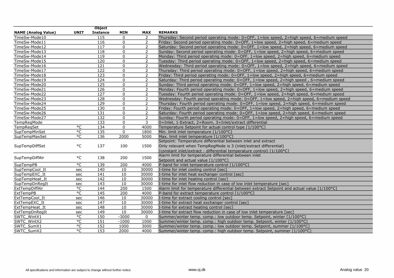
NAME (Analog Value) UNIT
Object
Instance MIN MAX REMARKS
TimeSw-Mode10 115 0 2 Thursday: Second period operating mode: 0=OFF, 1=low speed, 2=high speed, 6=medium speed
TimeSw-Mode11 116 0 2 Friday: Second period operating mode: 0=OFF, 1=low speed, 2=high speed, 6=medium speed
TimeSw-Mode12 117 0 2 Saturday: Second period operating mode: 0=OFF, 1=low speed, 2=high speed, 6=medium speed
TimeSw-Mode13 118 0 2 Sunday: Second period operating mode: 0=OFF, 1=low speed, 2=high speed, 6=medium speed
TimeSw-Mode14 119 0 2 Monday: Third period operating mode: 0=OFF, 1=low speed, 2=high speed, 6=medium speed
TimeSw-Mode15 120 0 2 Tuesday: Third period operating mode: 0=OFF, 1=low speed, 2=high speed, 6=medium speed
TimeSw-Mode16 121 0 2 Wednesday: Third period operating mode: 0=OFF, 1=low speed, 2=high speed, 6=medium speed
TimeSw-Mode17 122 0 2 Thursday: Third period operating mode: 0=OFF, 1=low speed, 2=high speed, 6=medium speed
TimeSw-Mode18 123 0 2 Friday: Third period operating mode: 0=OFF, 1=low speed, 2=high speed, 6=medium speed
TimeSw-Mode19 124 0 2 Saturday: Third period operating mode: 0=OFF, 1=low speed, 2=high speed , 6=medium speed
TimeSw-Mode20 125 0 2 Sunday: Third period operating mode: 0=OFF, 1=low speed, 2=high speed, 6=medium speed
TimeSw-Mode21 126 0 2 Monday: Fourth period operating mode: 0=OFF, 1=low speed, 2=high speed, 6=medium speed
TimeSw-Mode22 127 0 2 Tuesday: Fourth period operating mode: 0=OFF, 1=low speed, 2=high speed, 6=medium speed
TimeSw-Mode23 128 0 2 Wednesday: Fourth period operating mode: 0=OFF, 1=low speed, 2=high speed, 6=medium speed
TimeSw-Mode24 129 0 2 Thursday: Fourth period operating mode: 0=OFF, 1=low speed, 2=high speed, 6=medium speed
TimeSw-Mode25 130 0 2 Friday: Fourth period operating mode: 0=OFF, 1=low speed, 2=high speed, 6=medium speed
TimeSw-Mode26 131 0 2 Saturday: Fourth period operating mode: 0=OFF, 1=low speed, 2=high speed, 6=medium speed
TimeSw-Mode27 132 0 2 Sunday: Fourth period operating mode: 0=OFF, 1=low speed, 2=high speed, 6=medium speed
TempRegMode 133 0 3 0=Inlet, 1-Extract, 2=Room, 3=Inlet/extract differential
TempRegSet °C 134 0 4000 Temperature Setpoint for actual control type [1/100°C]
SupTempMinSet °C 135 0 1800 Min. limit inlet temperature [1/100°C]
SupTempMaxSet °C 136 2000 5000 Max. limit inlet temperature [1/100°C]
SupTempDiffSet °C 137 100 1500
Setpoint: Temperature differential between inlet and extract
Only relevant when TempRegMode is 3 (inlet/extract differential)
(constant inlet/extract - differential temperature control) [1/100°C]
SupTempDiffAlr °C 138 200 1500Alarm limit for temperature differential between inlet
Setpoint and actual value [1/100°C]SupTempPB °C 139 200 4000 P-band for inlet temperature control [1/100°C]
SupTempCool_It sec 140 10 30000 I-time for inlet cooling control [sec]
SupTempEXC_It sec 141 10 30000 I-time for inlet heat exchanger control [sec]
SupTempHeat_It sec 142 10 30000 I-time for inlet heating control [sec]
SupTempDnRegIt sec 143 10 30000 I-time for inlet flow reduction in case of low inlet temperature [sec]
ExtTempDiffAlr °C 144 200 1500 Alarm limit for temperature differential between extract Setpoint and actual value [1/100°C]
ExtTempPB °C 145 200 4000 P-band for extract temperature control [1/100°C]
ExtTempCool_It sec 146 10 30000 I-time for extract cooling control [sec]
ExtTempEXC_It sec 147 10 30000 I-time for extract heat exchanger control [sec]
ExtTempHeat_It sec 148 10 30000 I-time for extract heating control [sec]
ExtTempDnRegIt sec 149 10 30000 I-time for extract flow reduction in case of low inlet temperature [sec]
SWTC_WintX1 °C 150 -3000 0 Summer/winter temp. comp.: low outdoor temp. Setpoint, winter [1/100°C]
SWTC_WintX2 °C 151 -1000 1000 Summer/winter temp. comp.: high outdoor temp. Setpoint, winter [1/100°C]
SWTC_SumX1 °C 152 1000 3000 Summer/winter temp. comp.: low outdoor temp. Setpoint, summer [1/100°C]
SWTC_SumX2 °C 153 2000 4000 Summer/winter temp. comp.: high outdoor temp. Setpoint, summer [1/100°C]
All specifications and information are subject to change without further notice. www.oj.dk Analog value 20
NAME (Analog Value) UNIT
Object
Instance MIN MAX REMARKS
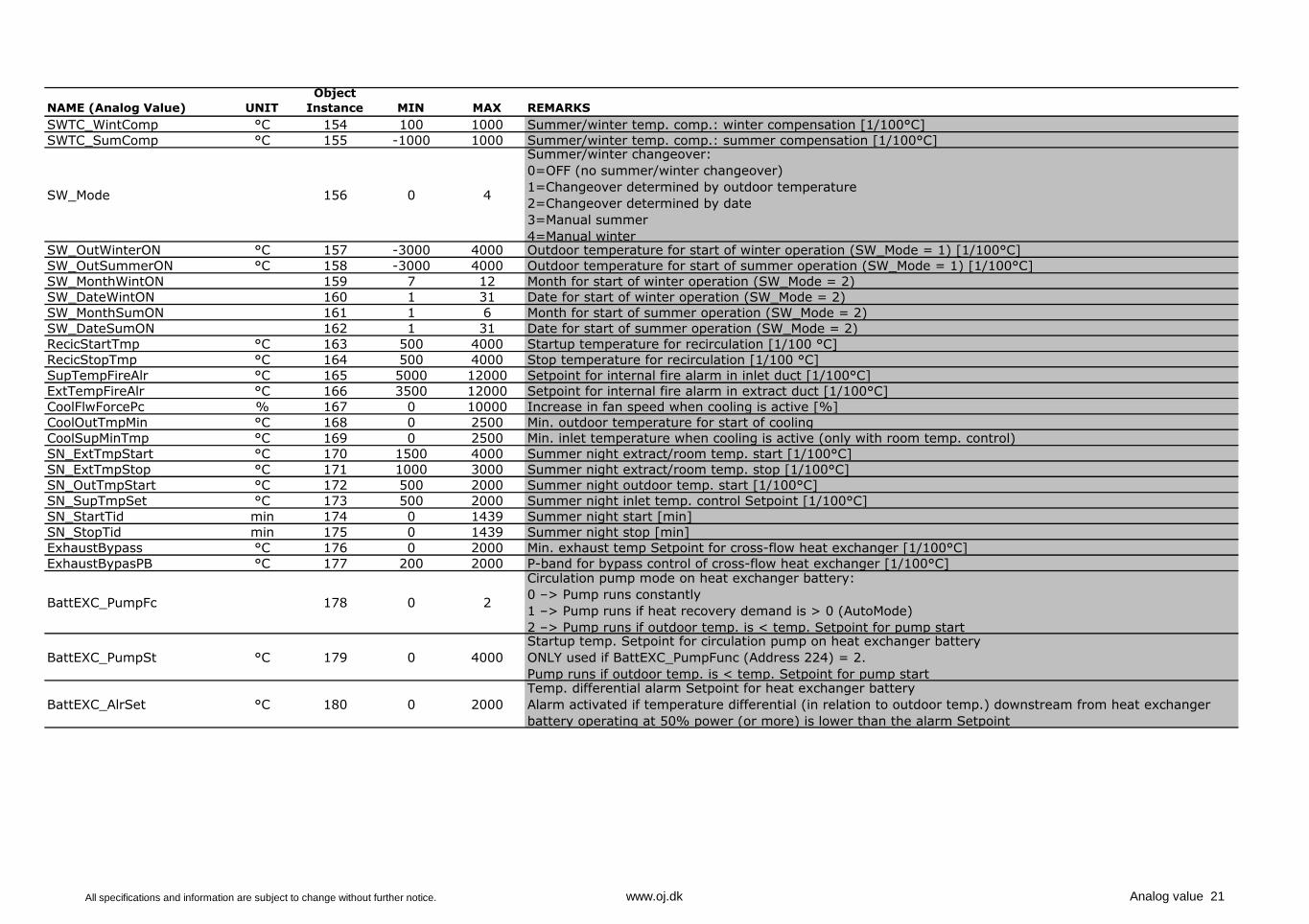
SWTC_WintComp °C 154 100 1000 Summer/winter temp. comp.: winter compensation [1/100°C]
SWTC_SumComp °C 155 -1000 1000 Summer/winter temp. comp.: summer compensation [1/100°C]
SW_Mode 156 0 4
Summer/winter changeover:
0=OFF (no summer/winter changeover)
1=Changeover determined by outdoor temperature
2=Changeover determined by date
3=Manual summer
4=Manual winter SW_OutWinterON °C 157 -3000 4000 Outdoor temperature for start of winter operation (SW_Mode = 1) [1/100°C]
SW_OutSummerON °C 158 -3000 4000 Outdoor temperature for start of summer operation (SW_Mode = 1) [1/100°C]
SW_MonthWintON 159 7 12 Month for start of winter operation (SW_Mode = 2)
SW_DateWintON 160 1 31 Date for start of winter operation (SW_Mode = 2)
SW_MonthSumON 161 1 6 Month for start of summer operation (SW_Mode = 2)
SW_DateSumON 162 1 31 Date for start of summer operation (SW_Mode = 2)
RecicStartTmp °C 163 500 4000 Startup temperature for recirculation [1/100 °C]
RecicStopTmp °C 164 500 4000 Stop temperature for recirculation [1/100 °C]
SupTempFireAlr °C 165 5000 12000 Setpoint for internal fire alarm in inlet duct [1/100°C]
ExtTempFireAlr °C 166 3500 12000 Setpoint for internal fire alarm in extract duct [1/100°C]
CoolFlwForcePc % 167 0 10000 Increase in fan speed when cooling is active [%]
CoolOutTmpMin °C 168 0 2500 Min. outdoor temperature for start of cooling
CoolSupMinTmp °C 169 0 2500 Min. inlet temperature when cooling is active (only with room temp. control)
SN_ExtTmpStart °C 170 1500 4000 Summer night extract/room temp. start [1/100°C]
SN_ExtTmpStop °C 171 1000 3000 Summer night extract/room temp. stop [1/100°C]
SN_OutTmpStart °C 172 500 2000 Summer night outdoor temp. start [1/100°C]
SN_SupTmpSet °C 173 500 2000 Summer night inlet temp. control Setpoint [1/100°C]
SN_StartTid min 174 0 1439 Summer night start [min]
SN_StopTid min 175 0 1439 Summer night stop [min]
ExhaustBypass °C 176 0 2000 Min. exhaust temp Setpoint for cross-flow heat exchanger [1/100°C]
ExhaustBypasPB °C 177 200 2000 P-band for bypass control of cross-flow heat exchanger [1/100°C]
BattEXC_PumpFc 178 0 2
Circulation pump mode on heat exchanger battery:
0 –> Pump runs constantly
1 –> Pump runs if heat recovery demand is > 0 (AutoMode)
2 –> Pump runs if outdoor temp. is < temp. Setpoint for pump start
BattEXC_PumpSt °C 179 0 4000
Startup temp. Setpoint for circulation pump on heat exchanger battery
ONLY used if BattEXC_PumpFunc (Address 224) = 2.
Pump runs if outdoor temp. is < temp. Setpoint for pump start
BattEXC_AlrSet °C 180 0 2000
Temp. differential alarm Setpoint for heat exchanger battery
Alarm activated if temperature differential (in relation to outdoor temp.) downstream from heat exchanger
battery operating at 50% power (or more) is lower than the alarm Setpoint
All specifications and information are subject to change without further notice. www.oj.dk Analog value 21
NAME (Analog Value) UNIT
Object
Instance MIN MAX REMARKS
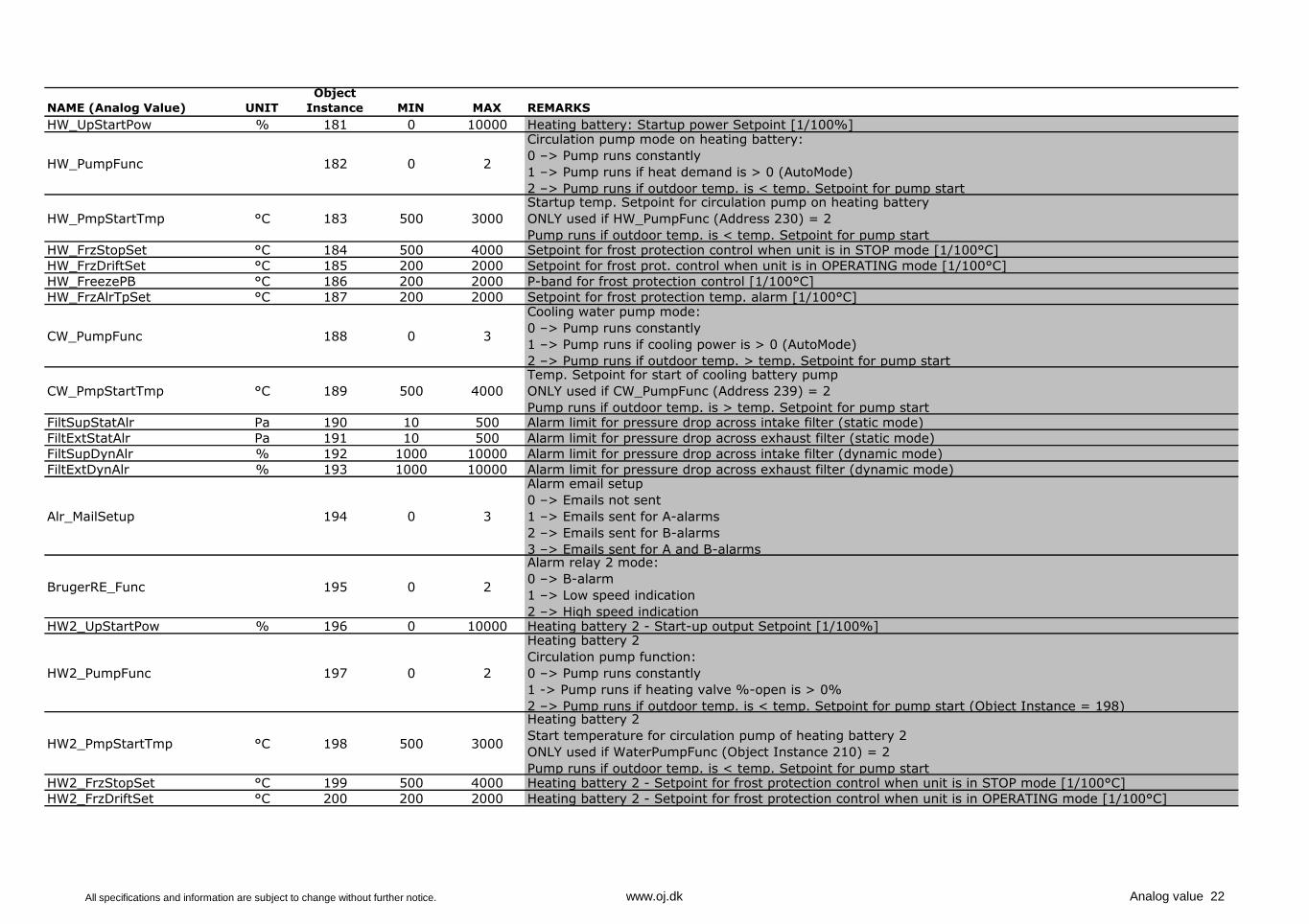
HW_UpStartPow % 181 0 10000 Heating battery: Startup power Setpoint [1/100%]
HW_PumpFunc 182 0 2
Circulation pump mode on heating battery:
0 –> Pump runs constantly
1 –> Pump runs if heat demand is > 0 (AutoMode)
2 –> Pump runs if outdoor temp. is < temp. Setpoint for pump start
HW_PmpStartTmp °C 183 500 3000
Startup temp. Setpoint for circulation pump on heating battery
ONLY used if HW_PumpFunc (Address 230) = 2
Pump runs if outdoor temp. is < temp. Setpoint for pump start HW_FrzStopSet °C 184 500 4000 Setpoint for frost protection control when unit is in STOP mode [1/100°C]
HW_FrzDriftSet °C 185 200 2000 Setpoint for frost prot. control when unit is in OPERATING mode [1/100°C]
HW_FreezePB °C 186 200 2000 P-band for frost protection control [1/100°C]
HW_FrzAlrTpSet °C 187 200 2000 Setpoint for frost protection temp. alarm [1/100°C]
CW_PumpFunc 188 0 3
Cooling water pump mode:
0 –> Pump runs constantly
1 –> Pump runs if cooling power is > 0 (AutoMode)
2 –> Pump runs if outdoor temp. > temp. Setpoint for pump start
CW_PmpStartTmp °C 189 500 4000
Temp. Setpoint for start of cooling battery pump
ONLY used if CW_PumpFunc (Address 239) = 2
Pump runs if outdoor temp. is > temp. Setpoint for pump startFiltSupStatAlr Pa 190 10 500 Alarm limit for pressure drop across intake filter (static mode)
FiltExtStatAlr Pa 191 10 500 Alarm limit for pressure drop across exhaust filter (static mode)
FiltSupDynAlr % 192 1000 10000 Alarm limit for pressure drop across intake filter (dynamic mode)
FiltExtDynAlr % 193 1000 10000 Alarm limit for pressure drop across exhaust filter (dynamic mode)
Alr_MailSetup 194 0 3
Alarm email setup
0 –> Emails not sent
1 –> Emails sent for A-alarms
2 –> Emails sent for B-alarms
3 –> Emails sent for A and B-alarms
BrugerRE_Func 195 0 2
Alarm relay 2 mode:
0 –> B-alarm
1 –> Low speed indication
2 –> High speed indication HW2_UpStartPow % 196 0 10000 Heating battery 2 - Start-up output Setpoint [1/100%]
HW2_PumpFunc 197 0 2
Heating battery 2
Circulation pump function:
0 –> Pump runs constantly
1 -> Pump runs if heating valve %-open is > 0%
2 –> Pump runs if outdoor temp. is < temp. Setpoint for pump start (Object Instance = 198)
HW2_PmpStartTmp °C 198 500 3000
Heating battery 2
Start temperature for circulation pump of heating battery 2
ONLY used if WaterPumpFunc (Object Instance 210) = 2
Pump runs if outdoor temp. is < temp. Setpoint for pump startHW2_FrzStopSet °C 199 500 4000 Heating battery 2 - Setpoint for frost protection control when unit is in STOP mode [1/100°C]
HW2_FrzDriftSet °C 200 200 2000 Heating battery 2 - Setpoint for frost protection control when unit is in OPERATING mode [1/100°C]
All specifications and information are subject to change without further notice. www.oj.dk Analog value 22
NAME (Analog Value) UNIT
Object
Instance MIN MAX REMARKS
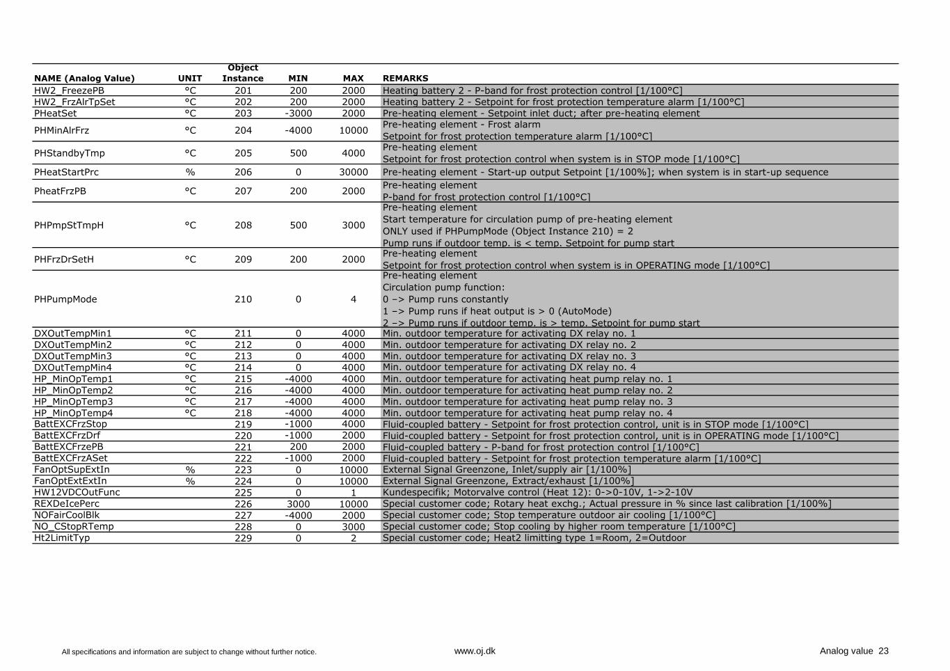
HW2_FreezePB °C 201 200 2000 Heating battery 2 - P-band for frost protection control [1/100°C]
HW2_FrzAlrTpSet °C 202 200 2000 Heating battery 2 - Setpoint for frost protection temperature alarm [1/100°C]
PHeatSet °C 203 -3000 2000 Pre-heating element - Setpoint inlet duct; after pre-heating element
PHMinAlrFrz °C 204 -4000 10000Pre-heating element - Frost alarm
Setpoint for frost protection temperature alarm [1/100°C]
PHStandbyTmp °C 205 500 4000Pre-heating element
Setpoint for frost protection control when system is in STOP mode [1/100°C]
PHeatStartPrc % 206 0 30000 Pre-heating element - Start-up output Setpoint [1/100%]; when system is in start-up sequence
PheatFrzPB °C 207 200 2000Pre-heating element
P-band for frost protection control [1/100°C]
PHPmpStTmpH °C 208 500 3000
Pre-heating element
Start temperature for circulation pump of pre-heating element
ONLY used if PHPumpMode (Object Instance 210) = 2
Pump runs if outdoor temp. is < temp. Setpoint for pump start
PHFrzDrSetH °C 209 200 2000Pre-heating element
Setpoint for frost protection control when system is in OPERATING mode [1/100°C]
PHPumpMode 210 0 4
Pre-heating element
Circulation pump function:
0 –> Pump runs constantly
1 –> Pump runs if heat output is > 0 (AutoMode)
2 –> Pump runs if outdoor temp. is > temp. Setpoint for pump startDXOutTempMin1 °C 211 0 4000 Min. outdoor temperature for activating DX relay no. 1
DXOutTempMin2 °C 212 0 4000 Min. outdoor temperature for activating DX relay no. 2
DXOutTempMin3 °C 213 0 4000 Min. outdoor temperature for activating DX relay no. 3
DXOutTempMin4 °C 214 0 4000 Min. outdoor temperature for activating DX relay no. 4
HP_MinOpTemp1 °C 215 -4000 4000 Min. outdoor temperature for activating heat pump relay no. 1
HP_MinOpTemp2 °C 216 -4000 4000 Min. outdoor temperature for activating heat pump relay no. 2
HP_MinOpTemp3 °C 217 -4000 4000 Min. outdoor temperature for activating heat pump relay no. 3
HP_MinOpTemp4 °C 218 -4000 4000 Min. outdoor temperature for activating heat pump relay no. 4BattEXCFrzStop 219 -1000 4000 Fluid-coupled battery - Setpoint for frost protection control, unit is in STOP mode [1/100°C]BattEXCFrzDrf 220 -1000 2000 Fluid-coupled battery - Setpoint for frost protection control, unit is in OPERATING mode [1/100°C]BattEXCFrzePB 221 200 2000 Fluid-coupled battery - P-band for frost protection control [1/100°C]BattEXCFrzASet 222 -1000 2000 Fluid-coupled battery - Setpoint for frost protection temperature alarm [1/100°C]FanOptSupExtIn % 223 0 10000 External Signal Greenzone, Inlet/supply air [1/100%]
FanOptExtExtIn % 224 0 10000 External Signal Greenzone, Extract/exhaust [1/100%]
HW12VDCOutFunc 225 0 1 Kundespecifik; Motorvalve control (Heat 12): 0->0-10V, 1->2-10V
REXDeIcePerc 226 3000 10000 Special customer code; Rotary heat exchg.; Actual pressure in % since last calibration [1/100%]
NOFairCoolBlk 227 -4000 2000 Special customer code; Stop temperature outdoor air cooling [1/100°C]
NO_CStopRTemp 228 0 3000 Special customer code; Stop cooling by higher room temperature [1/100°C]
Ht2LimitTyp 229 0 2 Special customer code; Heat2 limitting type 1=Room, 2=Outdoor
All specifications and information are subject to change without further notice. www.oj.dk Analog value 23
NAME (Analog Value) UNIT
Object
Instance MIN MAX REMARKS
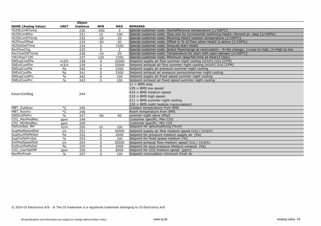
Ht2StLimRTemp 230 -500 0 Special customer code; Startdifference temperature [1/100°C]
Ht2StLimRPer 231 10 100 Special customer code; Step size by incremental switching Heat2; Percent pr. step [1/100%]
Ht2StLimOTemp 232 -20 20 Special customer code; Blocking Heat2 outdoor temperature [1/100°C]
Ht2FlowOffset 233 -50 50 Special customer code; Offset in % of Flow when Heat2 is aktive [1/100%]
Ht2SetDelTime 234 0 7200 Special customer code; Delayed start Heat2
RecFlowChg 235 0 2 Special customer code; Select flowchange at recircutaion - 0=No change; 1=Low to high; 2=High to low
RecClosDStTemp 236 -10 20 Special customer code; Temperature for start with open damper [1/100°C]
HW1RiseT100 237 120 7200 Special customer code; Minimum raise/fall time at Heat12 [Sec]
SNSupCoolFlw m3/h 238 0 32000 Setpoint supply air flow summer night cooling [m3/h] [l/s] [CFM]
SNExtCoolFlw m3/h 239 0 32000 Setpoint exhaust air flow summer night cooling [m3/h] [l/s] [CFM]
SNSupCoolPa Pa 240 0 2500 Setpoint supply air pressure summer night cooling
SNExtCoolPa Pa 241 0 2500 Setpoint exhaust air pressure somsummermer night cooling
SNSupCoolPrc % 242 0 100 Setpoint supply air fixed speed summer night cooling
SNExtCoolPrc % 243 0 100 Setpoint exhaust air fixed speed summer night cooling
MBT_Outdoor °C 245 Outdoor temperature from BMS
MBT_Room1 °C 246 Room temperature from BMS
SNSlvOffsPrc % 247 -50 50 summer night slave offset
CO2_MaxModRec ppm 248 Customer specific; Max CO2
CO2_MinModRec ppm 249 Customer specific; Min CO2DehumSet_RH %rH 250 10 100 Setpoint for dehumidifying [%rH]
SupMedSpeedSet l/s 251 0 30000 Setpoint supply air flow medium speed [l/s] / [m3/h]SupDuctPaMeSet Pa 252 0 2000 Setpoint for pressure medium supply air [Pa]SupFixMePrcSet % 253 0 100 Setpoint for fixed speed medium [%]
ExtMedSpeedSet l/s 254 0 30000 Setpoint exhaust flow-medium speed [l/s] / [m3/h]ExtDuctPaMeSet Pa 255 0 2000 Setpoint for duct pressure Medium exhaust [Pa]CO2_UserSetMP ppm 256 0 8000 Setpoint for CO2 medium speed [ppm]
RecMinFresh % 257 0 100 Setpoint recirculation minimum fresh air
© 2016 OJ Electronics A/S · ® The OJ trademark is a registered trademark belonging to OJ Electronics A/S
ExternCtrlReg 244
11 = BMS stop
105 = BMS low speed
414 = BMS medium speed
210 = BMS high speed
211 = BMS summer night cooling
220 = BMS night heating (recirculation)
All specifications and information are subject to change without further notice. www.oj.dk Analog value 24