Embed Size (px)
Citation preview
<< Back Home Next >>
OISD STANDARD-162 First Edition July 1995 For Restricted Circulation only No.
SAFETY IN INSTALLATION AND MAINTENANCE OF
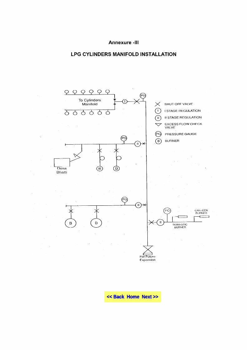
LPG CYLINDERS MANIFOLD
Prepared By COMMITTEE ON LPG CYLINDERS MANIFOLD
OIL INDUSTRY SAFETY DIRECTORATE 7TH FLOOR, NEW DELHI HOUSE
27, BARAKHAMBA ROAD NEW DELHI - 110 001.
NOTE
OISD (Oil Industry Safety Directorate) publications are prepared for use in the oil and gas industry under Ministry of Petroleum and Natural Gas. These are the property of Ministry of Petroleum and Natural Gas and shall not be reproduced or copied and loaned or exhibited to others without written consent from OISD. Though every effort has been made to assure the accuracy and reliability of the data contained in these documents, OISD hereby expressly disclaims any liability or responsibility for loss or damage resulting from their use. These documents are intended to supplement rather than replace the prevailing statutory requirements.
FOREWORD
Oil Industry in India is more than 100 years old. Over the years a variety of practices have been in vogue because of collaboration/association with different foreign companies and governments. Standardisation in design, operating and maintenance practices was hardly in existence at a national level. This lack of uniformity, coupled with feed back from some serious accidents that occurred in the recent past in India and abroad, emphasised the need for the industry to review the existing state of art in designing, operating and maintaining oil and gas installations.
With this in view, the Ministry of Petroleum & Natural Gas in 1986
constituted a Safety Council assisted by the Oil Industry Safety Directorate (OISD) staffed from within the industry in formulating and implementing a series of self regulatory measures aimed at removing obsolescence, standardising and upgrading the existing standards to ensure safer operations. Accordingly, OISD constituted a number of functional committees comprising of experts nominated from the industry to draw up standards and guidelines on various subjects.
The present document on ‘Safety in installation and maintenance of LPG cylinders manifold’ was prepared by the functional committee on LPG Cylinders Manifold. This document was prepared based on the accumulated knowledge and experience of industry members and the various national and international codes and practices.
This document will be reviewed periodically for improvements based on the new experiences and better understanding.
Suggestions from industry members/users may be addressed to :
The Coordinator Committee on
LPG Cylinders Manifold OIL INDUSTRY SAFETY DIRECTORATE
7TH FLOOR, NEW DELHI HOUSE 27, BARAKHAMBA ROAD
NEW DELHI - 110 001.
COMMITTEE ON
LPG CYLINDERS MANIFOLD Members Representing SHRI A.K. VATTS INDIAN OIL CORPN. LTD. (LEADER) (MARKETING DIVISION) SHRI K.V. APTE HINDUSTAN PETROLEUM CORPN. LTD. (MARKETING) SHRI S. ELANGO BHARAT PETROLEUM CORPN. LTD. (MARKETING) SHRI S.C. GUPTA OIL INDUSTRY SAFETY (CO-ORDINATOR) DIRECTORATE -------------------------------------------------------------------------------------------------------------------------------------- In addition to the above, several other experts from industry contributed in the preparation, review and finalisation of this document.
SAFETY IN
INSTALLATION AND MAINTENANCE OF LPG CYLINDERS MANIFOLD
CONTENTS -------------------------------------------------------------------------------------------------------------------------------------- SECTION -------------------------------------------------------------------------------------------------------------------------------------- 1.0 INTRODUCTION 2.0 SCOPE 3.0 LAYOUT 4.0 DESIGN CRITERIA OF INSTALLATION 5.0 SPECIFICATIONS FOR EQUIPMENTS, APPLIANCES & ACCESSORIES 6.0 INSTALLATION OF PIPING AND VALVES 7.0 PRE-COMMISSIONING CHECKS 8.0 MAINTENANCE OF CYLINDERS MANIFOLD 9.0 SAFE OPERATING PRACTICES AND LEAK TESTING ANNEXURES --------------------------------------------------------------------------------------------------------------------------------------
SAFETY IN INSTALLATION AND MAINTENANCE OF LPG CYLINDERS MANIFOLD
1.0 INTRODUCTION There are a number of LPG cylinders manifolded installations existing in Hotels, Hospitals, Nursing Homes etc. Apart from a BIS code, there is no detailed code which can be followed by the Oil Industry (through their approved contractors). In view of the potential hazards of such manifold installations, the need was felt to develop a standard code of practice in addition to BIS code IS:6044 (Part I)-1971. In the Liquefied Petroleum Gas trade, commercial/Industrial cylinders installations relate to the larger type catering/production arrangements such as Restaurants and Canteens located in Hotels, Hospitals, Nursing Homes and Industrial Establishments such as Textiles, Baking, Glass factory etc. 2.0 SCOPE This Standard : - Covers LPG cylinders (all types approved by CCE) connected through a manifold to commercial/ domestic, industrial burners where the end use of LPG is for Commercial cooking/ production/ Laboratory purposes. - Supplements IS:6044 (part I) - 1971 on guidelines for packed cylinder installation. Items covered under IS:6044 (part I) - 1971 are not being repeated and this standard may be referred in conjunction with IS: 6044 (Part I) - 1971. - Relates to safe practices in Design, erection, commissioning and maintenance of manifold installations. However, detailed operational practices like handling emergencies etc. are not covered. Oil industry is in the process of drawing out detailed specifications of the equipments used in the manifolded LPG cylinders installations. All equipments used in these installations shall meet the above specifications. For replacement schedules in the installation, equipment guidelines suggested by the manufacturers may be followed.
3.0 LAYOUT 3.1 General guidelines for manifolded LPG cylinders shall be followed from IS : 6044 (Part I) - 1971. The additional safety measures need to be taken are as under: 3.2 The site for LPG cylinder manifold shall be located away from the kitchen. Installation shall be slightly raised from the ground level. Cylinders shall not be installed below ground level in cellars or basement. The cylinders shall be stored in dry, cool and well ventilated room. 3.3 Cylinders installation should not be located close to steam pipes and boilers etc. to prevent cylinders from getting affected due to radiant heat. 3.4 Cylinders shall not be installed at a place where they are likely to cause obstruction, suffer damage or be exposed to conditions likely to affect safety. 3.5 The cylinder storage room shall be of fire - resistant construction. Flammable materials like wood and plastic shall not be used. 3.6 Cylinders shall be located on a concrete or brick floor in case of outdoor installation. The cylinder shall be installed in upright position with the valve pointing upwards. 3.7 Since LPG is heavier than air, ventilation shall be provided at floor level open to atmosphere. The ventilators shall be provided with 2 layers copper or non - corroding metal wire mesh not less than 11 to the linear centimeter. 3.8 Safety cap should be put on the cylinders which are empty. 3.9 The doors of the room where cylinders are installed shall open outwards.
3.10 Main shut-off valve (Plug or ball-type) on the pipeline emerging out of cylinder storage room shall be located in such a manner that it just falls outside the storage room and shall be easily accessible at all times. At the point of entry of each work place, the line shall have a quick shut off valve (plug or ball-type). 3.11 The main shut - off and quick shut-off valves are required in case the distance between the storage room and the work place is more than 10 mtrs. 3.12 As per Statutory requirements no explosive license is required for multi cylinder installations. However, consumers having unconnected filled cylinders with more than 100 kgs. LPG shall obtain explosives license under Gas Cylinders Rules 1981. 3.13 The safety distance of packed installation shall conform to Rule 3.1.6. of IS:6044 (Part I) - 1971. 3.14 Wherever the pipelines are passing through walls, slacks shall be provided so that the pipeline does not get abraized. 3.15 The storage room shall have caution signs such as “DANGER”, “HIGHLY INFLAMMABLE GAS SHED”. “NO SMOKING” etc. painted in luminous red paint outside at a prominent place. 3.16 A minimum distance of 1 mt. shall be maintained between the cylinder installation and the surface water drain, if any. 4.0 DESIGN CRITERIA OF INSTALLATION 4.1 In order to meet the larger requirement of commercial customers it is necessary to connect a number of cylinders to a manifold so that the required quantity of gas at requisite pressure can be obtained. The multi cylinder installations shall be designed as per IS:6044 (part I) - 1971. 4.1.1 It is required to visit the customer’s premises and select a suitable site for cylinder storage room as per the layout considerations. In order to ascertain the requirement complete details shall be collected and noted in the format as given in annexure - I.
4.2 Requirement of Cylinder Bank/Burners : Multi- cylinder manifolds are mainly designed and used for cooking purpose. The LPG requirement of customers desirous of converting from other fuels to LPG can be assessed based on the quantity of fuel used, its calorific values and heat transferring efficiency. 4.2.1 In the case of absolutely new installations the requirement may be assessed alternatively by taking normal consumption per person per day from 0.1 to 0.13 kg. depending upon the climatic conditions. For existing as well as the new customers the no. of cylinders required to be in use may be assessed after taking into account the burner consumption rate of LPG, % utilization during the usage and the natural vapourisation capacity per cylinder. 4.2.2 Provision should also be made for 100% spare capacity for cylinders as calculated above. 4.2.3 While deciding at the size of the manifold it should preferably be designed for higher no. of cylinders to accommodate for increase in consumption in future. 4.2.4 Size of the cylinder storage room shall depend upon the number of installed cylinders designed for the layout of the manifold (parallel or linear) and the cylinder arrangement in the storage room (Standard or staggered). Enough room shall be provided for easy access to each and every cylinder. 4.3 CONNECTION CRITERIA OF LPG
CYLINDERS TO MANIFOLD : 4.3.1 All The cylinders at the customers’ premises shall always be connected to the manifold wherever the installed cylinders at the premises are more than four. The cylinders should not be left unconnected or stored elsewhere. Should there be requirement of additional cylinders which are to be kept loose, the customer can store them within stipulations as provided for in Gas Cylinders Rules, 1981. However such cylinders should not be stored in manifolded room. Each arm of the manifold shall have a control valve. To each arm of the cylinder manifold, cylinders shall be connected through a pigtail. For ‘SC’ type valve cylinders it is necessary to use an adaptor to connect the cylinder pigtail. The distance between the nipples on the manifold to which

pigtails are attached, depends upon the type of cylinder arrangement required i.e., standard or staggered. The staggered arrangement is to be used when availability of space is limited. 4.3.2 The flexible hose/pigtail shall be in the same room and its length shall not exceed 2 M. Flexible hose/ pigtail shall not pass through doors, windows, walls, ceiling (or) floors. The pigtails shall be accessible for inspection. 4.4 LOCATION FOR MANIFOLDED INSTALLATIONS: 4.4.1 Manifolded installations upto 40 kgs LPG can be installed on any floor. Minimum floor area required 5M 2. 4.4.2 Manifold installations not exceeding 40 kgs. of LPG may be installed in doors on any floor within the same workspace provided the minimum distance between two such installations is 3 M. The floor area for each installation should be at least 5M 2 and the aggregate quantity of LPG in all such installations does not exceed 200 kgs. 4.4.3 Manifolded installations not exceeding 80 kgs. of LPG may be installed indoors on any floor provided the floor area is not less than 12 M2 for such installation. 4.4.4 Manifolded installation not exceeding 80 kgs. of LPG may be installed indoors on any floor area provided the minimum distance between the installations is 3 M, the proportion of such installations to floor area is one installation per 12 M2 and the aggregate quantity of LPG in all such installations does not exceed 200 kgs. 4.5 As per IS:6044 (Part I) - 1971, small manifold (i.e. Total capacity upto 320 kgs) can be accommodated within the building. For bigger manifold (i.e. capacity 321 to 1000 kgs) a separate shed away from the main building shall be provided keeping adequate safety distances. For manifold capacity requirement of more than 1000 kgs, separate installations each not exceeding 1000 kgs. shall be provided. 4.6 The manifold (header) pipeline shall not have any joints to extend its length. 5.0 SPECIFICATIONS FOR EQUIPMENTS, APPLIANCES AND ACCESSORIES
5.1 GENERAL : 5.1.1 For safe efficient performance of any LPG installation, all equipments, appliances and accessories shall conform to the laid down standards and specifications. For quality control more and more items are being covered by BIS. In case of BIS covered items, items approved by BIS only shall be used. In case any component is not covered by BIS Standard, then the same shall have Oil Industry’s approval. 5.1.2 A list of such approved manufacturers for various components can be had from the concerned oil company. 5.1.3 Major components of LPG installation are briefly described below: 5.2 PRESSURE REGULATORS : 5.2.1 Pressure Regulators are devices used to regulate the delivery pressure to the appliances for safe operation. Adequate attention should be given to the Pressure Regulator selection and it must be chosen with due care. It shall have sufficient capacity to handle the volume of the gas required to supply maximum demand. The different types of pressure regulators presently available are : - low pressure regulators with high volume. - high pressure regulators with fixed outlet pressure. - high pressure regulators with variable outlet pressures. 5.2.2 All high pressure regulators to be used in LPG installations shall be of approved type. Only oil industry approved high pressure regulators shall be used. 5.2.3 If the regulator selection is not proper the appliance performance will be affected by pressure fluctuations and will induce a slow pulsation in line pressure causing appliance flame to vary. 5.3 GAS PIPES : 5.3.1 Copper, steel and mild steel tubes to be used in LPG service shall be as specified in IS:6044 (Part I) - 1971. 5.3.2 Steel pipes, cold steel drawn seamless or electric resistance welded

(ERW) conforming to IS:3601 shall only be used. 5.3.3 Copper tubes shall be solid drawn with outside diameter of 10, 12, 20 mm as suitable conforming to IS:2501. 5.4 VALVES : 5.4.1 The following types of valves are normally used in the LPG installations: i) Needle control valves ii) Fire control valves iii) Quick shut-off valves iv) Main shut-off valves 5.4.2 The valves designed to work on LPG shall only be used. Materials used in these valves should not be affected by LPG. Type of valves to be used on LPG service should be of proper pressure rating and meet oil industry specifications since BIS or equivalent standards are presently not available. 5.4.3 Cast iron and aluminum valves shall not be used. 5.5 BURNERS : 5.5.1 The burners used in commercial installations are normally high pressure burners. These burners work at a pressure of 0.315 kg/cm2 (4.5 PSIG) and above. Of the various models currently in use, from types which find the maximum applications are outlined below: 5.5.2 T-TYPE BURNERS OR TORCH BURNERS These give a concentrated flame and are good for water heating and deep frying. The vessels used in this type of burners should preferably have concave bottom. 5.5.3 These are vertical burners and height can be varied. 5.5.4 There are mainly two sizes in this type of burners i.e. T22 and T35 with consumption of 1 kg/hr and 1.6 kg/hr LPG respectively. These burners are also called as T1 and T2. Higher capacity burners are also available. There are no BIS specifications so far. Hence oil industry approved make shall only be used. 5.5.5 ‘M’ TYPE BURNERS
These have a spreading ring flame profile and are good for cooking purpose. These burners are referred to as ‘M’ type burners. There are no BIS specifications so far. Hence, Oil industry approved make shall only be used. 5.5.6 ‘V’ RING OR ‘L’ BURNERS These are long burners used horizontally and named ‘V’ burners due to their shape. These burners are used for heating long, broad containers mussel ovens etc. The burner flame impinges on the bottom of the vessel or plate at an angle of 45 degrees. The burner shall be so chosen such that the flame does not enter beyond the circumference of bottom plate of vessel. 5.5.7 CANTEEN BURNERS 5.5.7.1 These burners are low pressure appliances widely used in commercial installations. These are similar to the domestic burner but of larger size. 5.5.7.2 Canteen burners shall conform to IS:5517 - 1969. 5.5.7.3 High pressure canteen burners as may be required by end users can be custom - built and used. The heat efficiency of all the burners mentioned above should be a minimum of 40% when tests are conducted as per BIS Standard No. IS:5117-1969. 5.6 CYLINDERS MANIFOLD : 5.6.1 Cylinder manifold is very important because of the fact that it is subjected to full cylinder pressure at all times. The fabrication/ welding of the manifold should be of the best available quality. All such manifolds shall be designed to a pressure equivalent to the maximum possible cylinder pressure (assessed at 65 degree C) of LPG i.e. at 16.87 kgf/cm2. The test pressure should be 1.5 times the maximum pressure (assessed at 65 degree C) i.e. 25.35 kgf/cm2. 5.6.2 The control valve (‘F’ type ) used in the cylinder manifold arm shall be of the type used for LPG cylinders. Valves manufactured by approved valve manufacturers of oil industry shall only be used in manifold. 5.6.3 All joints in the manifold should be welded (except for valve fixation) and be easily accessible for inspection/ repairs etc.
5.6.4 Each manifold arm shall be fabricated out of a single length of pipe. Joints to lengthen the arm, are not permitted. 5.7 CYLINDER PIGTAILS : Normally copper pigtails are used to connect cylinders to the manifold. However, flexible reinforced synthetic rubber pipes are also being used. The quality of braided synthetic rubber tubes shall be such that it is least affected by LPG. The reinforcement i.e. braiding should be able to withstand the same pressure as that of cylinder manifold. The design and test criteria shall be same as that of cylinder manifold. Test pressure shall not be less than 25.35 /cm2. The free nut at the end shall be of noncorrosive metal. 5.8 ADAPTOR : This device is used to connect the pigtails to the cylinder valves (self-closing) of the LPG cylinders. This device shall have non-return device and shall have prior approval of the oil industry. 5.9 NEEDLE CONTROL VALVE : These are normally used to control the flow of gas to the burners. These valves should be of approved type of oil industry. 5.10 PRESSURE GAUGE : A good quality pressure gauge with a range of 0-3 kgf/cm2 (0-40 PSI) shall be provided in the pipeline after the first stage pressure regulator. The joint at which pressure gauge is fixed shall be thoroughly checked for leakage. Similar type of pressure gauges shall be provided in the pipelines after II stage regulation. 5.11 EXCESS FLOW VALVE : The excess flow check valve shall be provided on each arm of the manifold to ensure stoppage of LPG supplies in case of heavy leakage/damage to the pipeline in the downstream facilities. The capacity of the excess flow valve shall be 50% more than the maximum designed flow rate required through the manifold. 5.12 PIPING TUBING AND FITTINGS : Proper record of suppliers of equipments, its installation and Standard used shall be maintained.
6.0 INSTALLATION OF PIPING AND
APPLIANCES 6.1 In fabrication of LPG installation general guidelines shall be drawn from code of practice for LPG storage installation IS : 6044 (Part I)-1971. 6.2 Those responsible for the installation of LPG equipment and piping etc. should understand the characteristics of LPG very clearly and shall be trained in proper handling, installing and maintaining installations. 6.3 Detailed drawings giving specifications of the equipment used and layout of the entire installation must be approved by concerned Oil Co. before undertaking work. 6.4 The route of pipeline which is spelt out very clearly in the approved drawing, shall not deviate while laying down the pipelines. If need be the original drawings can be got revised duly approved by Oil Cos. 6.5 All pipelines must be either welded or brazed so as to ensure that no leakage can take place even at pressures much higher than the working pressures. Use of threading and jointing the pipeline through jointing compound shall not be resorted to. 6.6 The welding/brazing of the pipeline joints shall be done by a trained and qualified welder. 6.7 If the pipeline diameter is more than 50 mm, it should be welded and/or flanged. Smaller diameter pipelines should only be welded/brazed. 6.8 The piping joints shall not be placed embedded in floors in inaccessible places. Wherever it cannot be helped, welding and prior pressure testing of pipeline shall be done. Wherever the pipes are buried they shall not have any flange joints in the buried portion. 6.9 Joints other than welded, if any, are to be so placed that they shall be readily accessible, so that leakage tests can be conducted without any difficulty. 6.10 Piping both embedded in floor and above ground shall be protected against physical damage and corrosion. These shall be covered with bituminous wrap coating at the buried portion for LPG.
6.11 Cast iron and aluminum pipe fittings shall not be used. 6.12 All materials including non-metallic parts for valves, seals, gaskets and diaphragms shall be resistant to the action of the LPG under the service conditions to which they are subjected. 6.13 Plugs shall be solid steel plugs or steel ball plugs. Cast iron or brass plugs shall not be used. 6.14 Copper or brass pipe or tubing shall be seamless and shall only be used. for sizes 12.5 mm and under. 6.15 The pipeline connecting the storage shed to the main installation should preferably be brought overhead without creating any hazard for the people/vehicles passing through the same. In case of any foreseen hazard the pipeline can be laid embedded in the ground. 6.16 Quick shut-off valves designed to work on LPG, shall only be used for mainline for shut-off operations. The jointing compound shall be of Industry approved type. 6.17 No heating devices of any nature are permitted to be installed in the storage shed. Similarly, pipelines location shall be such so as to avoid any over heating/cooling at any length of the pipeline. 6.18 The single stage pipeline network (down the range of first stage pressure regulator) from the storage shed onward should work at pressure very close to the working pressure of the appliances. Under no circumstances, the pressure of the pipelines should exceed 22 PSI (1.5 kg/cm2). This should be obtained by double stage regulation of pressure, if necessary. A typical layout of installation is given in Annexure III. 6.19 Water spray of 10 liters PM/M2 on LPG manifold (with connected LPG cylinders) may be considered depending on installation size. 6.20 Whenever cylinders are taken out of manifold after closing the isolating valve, the idle ends of adaptor end shall be plugged with dummy valves (if new cylinders are not fixed) to avoid leakage from adaptor end to atmosphere. 7.0 PRE-COMMISSIONING CHECKS
7.1 Every multi-cylinder installation essentially consists of the following: 1. Cylinders 2. Manifold 3. Valves 4. Pigtails 5. Regulators 6. Burners It shall be ensured that all the above equipments conforms to a approved layout drawing and other specifications as mentioned in the foregoing sections. 8.0 MAINTENANCE OF CYLINDErs
MANIFOLD Maintenance of the cylinders manifold and the equipments shall be undertaken regularly and the periodicity of the maintenance shall be as under: 8.1 PERIODICITY : i) Valves : All the valves i.e. needle valves, manifold control valves emergency valve shall be checked once in a year. ii) Piping and manifold: It should be checked once a year visually. pneumatic testing of pipe lines once in 5 years. iii) HP & LP Regulators once a year for its accurate throttled pressure. iv) The burners shall be regularly cleaned. v) Pigtails shall be checked every time empty cylinder is replaced by a filled cylinder and replaced in case of any physical damage. 8.2 INSPECTING AUTHORITY : 1) All the manifold installations shall be checked once in six months by the dealers authorised mechanic and record maintained at the installation location. 2) The installation shall be checked once in a year by the concerned Oil company Sales Officer of the area or by any authorised representatives of the Oil Co. 3) Major installations shall also be inspected by Senior Officials of the Oil Co. The inspection shall be carried out as per the check list attached. (Annexure II)
9.0 SAFE OPERATING PRACTICES AND LEAK TESTING
9.1 All the safety precautions outlined in the Gas Cylinder Rule 1981 shall be complied with. 9.1.1 Storage of Cylinders i) The storage of cylinders is governed by the Gas Cylinders Rules - 1981 and the appropriate safety distances as given in the rule should be complied with. ii) Cylinders shall be stored in a cool, dry, well ventilated place under cover, away from boilers open flames, steam pipes or any potential sources of heat and such place of storage shall be easily accessible. iii) The storage room or shed shall be of fire resistant construction. iv) LPG filled cylinders must never be stacked in horizontal position. v) Cylinders containing flammable gases shall be kept separated from each other and from cylinders containing other types of gases by an adequate distance or by a suitable partition wall. vi) Cylinders shall not be stored under conditions which will cause them to corrode. vii) Cylinders shall not be stored along with any combustible material. viii) Unconnected cylinders shall be kept away from the LPG cylinder manifold. ix) All electric meters, distribution boards, switches, fuses, plugs and sockets, electric fixed lamps, portable hand lamps and motors shall be of flame-proof construction. 9.1.2 Handling and Use i) Cylinders shall be adequately supported during handling. ii) Trolleys and cradles of adequate strength shall as far as possible be used when moving the cylinders. Use of high powered magnets for lifting the cylinders and chains for slinging the cylinders shall not be permitted. Valve or any other fitting on the cylinder should not be lubricated. iii) The cylinders shall be handled carefully and not be allowed to fall upon one
another or otherwise subjected to any undue shock. iv) Sliding, dropping or playing with cylinders is prohibited. v) Liquefied Petroleum Gas cylinders shall always be kept in an upright position and shall be so placed that they cannot be knocked over. vi) Open flames, lights, lighting of fires, welding and smoking shall be prohibited in close proximity. Cylinder should not be lifted with magnets and chains should not be used for slinging. 9.2 LEAK TESTING: 9.2.1 Criteria For Leak Testing i) It shall be ensured that the manifold provided has been subjected to the test pressure of 25.35 kgf/cm2 (360 psig) at least for a minimum period of 1 hour inspected by the Oil Industry approved contractor. ii) It shall be ensured that the fire extinguisher and sand buckets are provided and installations are adequately protected from weather conditions. 9.2.2 Detection of Gas Leakages Gas leakage can be easily detected by its characteristic smell and more positively located by means of a soap solution. 9.2.3 For pinpointing the source of leakage only soap solution shall be used. A NAKED FLAME MUST NEVER BE USED because there is risk of causing fire accident. 9.2.4 Source of Leakages A. Cylinders : I) Welded seams ii) The cylinder/valve connection bung
joint. iii) Cylinder valve B. Check leakage from Pressure Regulator at : i) Near the joints.
ii) In the pressure regulator itself. iii) Check leakage from the piping and
manifold Regulator and the appliance inlet
nozzle. iv) Check leakage from cooking appliances at i.) All threaded connections. ii.) The appliances itself. 9.3 ACTION TO BE TAKEN WHEN
LEAKAGE IS DETECTED i) Leakage of cylinder: Any cylinder which develops a leak should be promptly removed to an isolated open place away from any source of ignition. ii) In case of leakages of piping, appliances or pressure regulators, close the valves and isolate the part, disconnect the cylinders and place the safety cap on the valve of the cylinder. NEVER repair the appliance or any other part of system when in use.
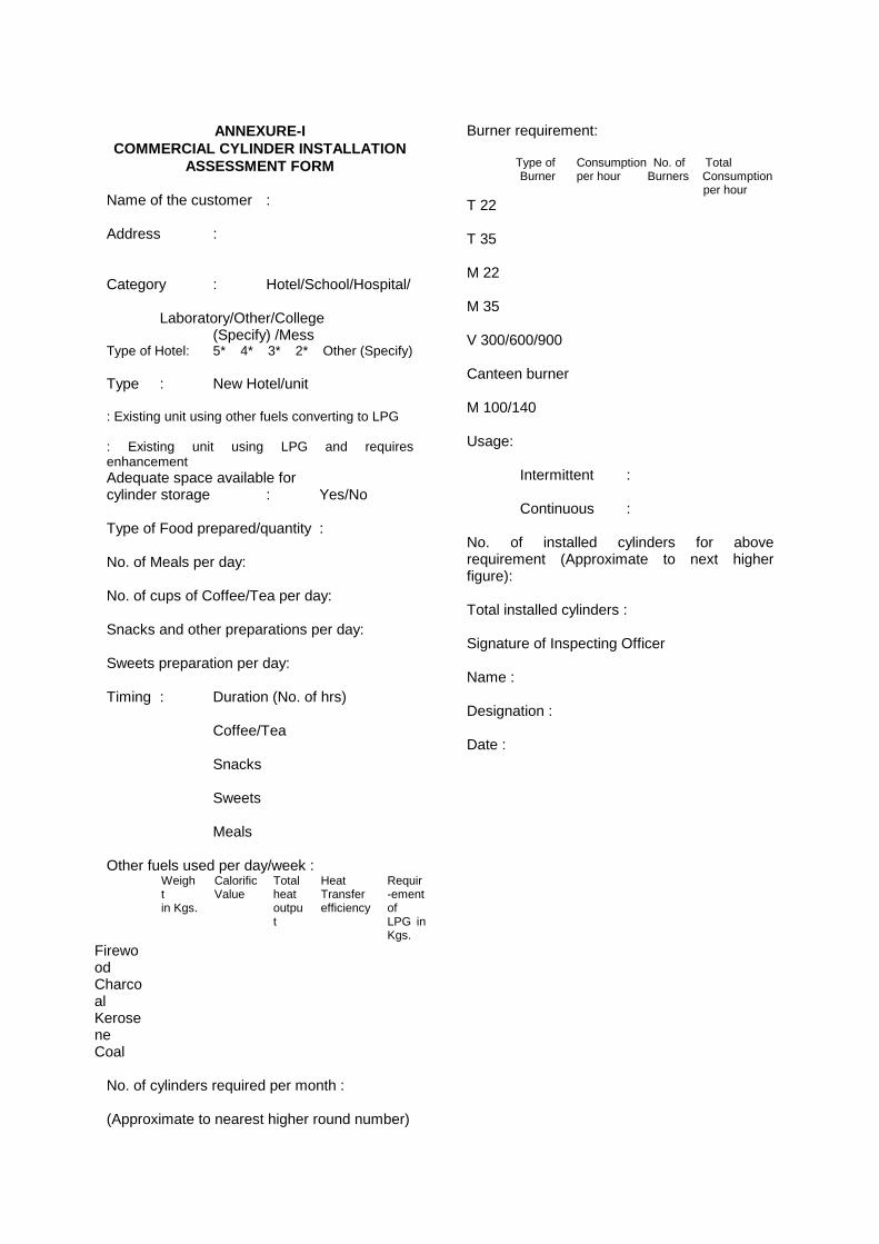
ANNEXURE-I
COMMERCIAL CYLINDER INSTALLATION ASSESSMENT FORM
Name of the customer : Address : Category : Hotel/School/Hospital/ Laboratory/Other/College (Specify) /Mess Type of Hotel: 5* 4* 3* 2* Other (Specify) Type : New Hotel/unit : Existing unit using other fuels converting to LPG : Existing unit using LPG and requires enhancement Adequate space available for cylinder storage : Yes/No Type of Food prepared/quantity : No. of Meals per day: No. of cups of Coffee/Tea per day: Snacks and other preparations per day: Sweets preparation per day: Timing : Duration (No. of hrs) Coffee/Tea Snacks Sweets Meals Other fuels used per day/week :
Weight in Kgs.
Calorific Value
Total heat output
Heat Transfer efficiency
Requir-ement of LPG in Kgs.
Firewood
Charcoal
Kerosene
Coal No. of cylinders required per month : (Approximate to nearest higher round number)
Burner requirement: Type of Consumption No. of Total Burner per hour Burners Consumption per hour T 22 T 35 M 22 M 35 V 300/600/900 Canteen burner M 100/140 Usage: Intermittent : Continuous : No. of installed cylinders for above requirement (Approximate to next higher figure): Total installed cylinders : Signature of Inspecting Officer Name : Designation : Date :
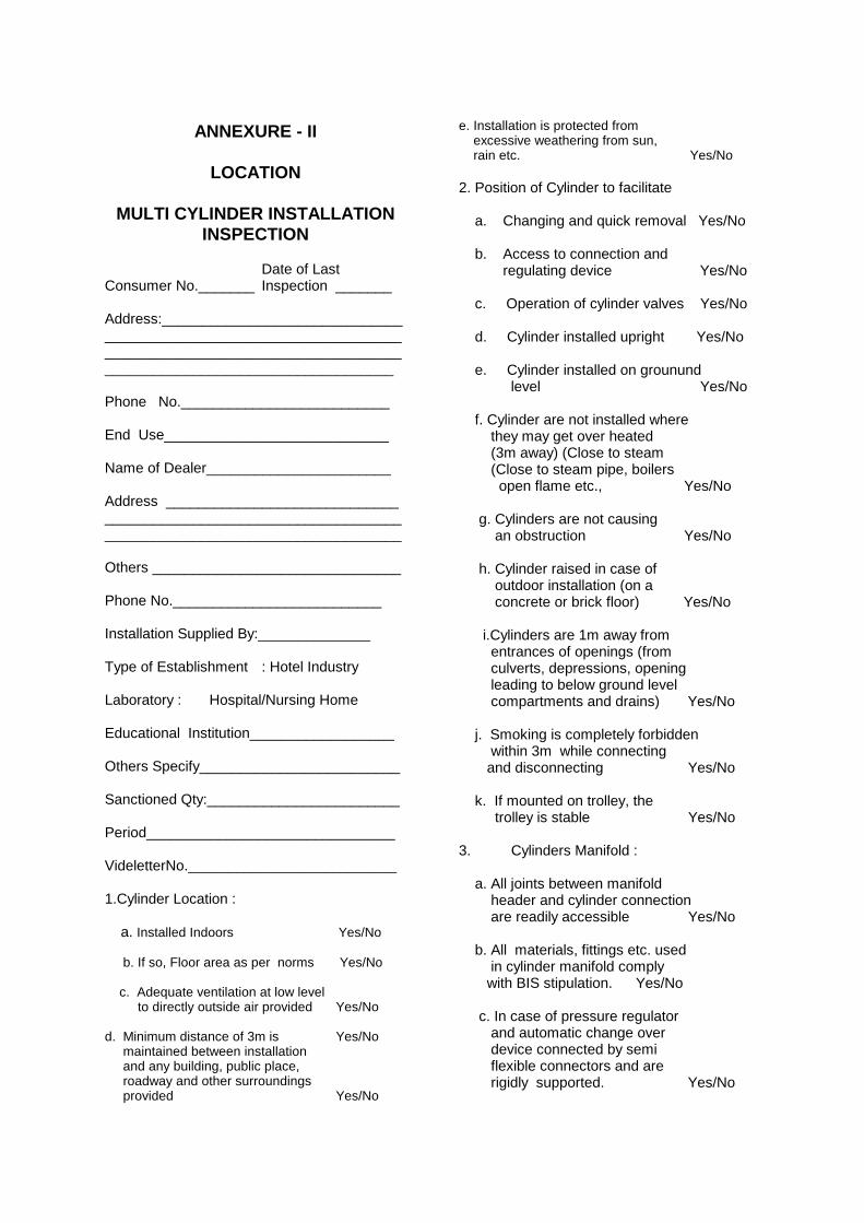
ANNEXURE - II
LOCATION
MULTI CYLINDER INSTALLATION
INSPECTION Date of Last Consumer No._______ Inspection _______ Address:____________________________________________________________________________________________________________________________________________ Phone No.__________________________ End Use____________________________ Name of Dealer_______________________ Address _____________________________ _____________________________________ _____________________________________ Others _______________________________ Phone No.__________________________ Installation Supplied By:______________ Type of Establishment : Hotel Industry Laboratory : Hospital/Nursing Home Educational Institution__________________ Others Specify_________________________ Sanctioned Qty:________________________ Period_______________________________ VideletterNo.__________________________ 1.Cylinder Location : a. Installed Indoors Yes/No b. If so, Floor area as per norms Yes/No c. Adequate ventilation at low level to directly outside air provided Yes/No d. Minimum distance of 3m is Yes/No maintained between installation and any building, public place, roadway and other surroundings provided Yes/No
e. Installation is protected from excessive weathering from sun, rain etc. Yes/No 2. Position of Cylinder to facilitate a. Changing and quick removal Yes/No b. Access to connection and regulating device Yes/No c. Operation of cylinder valves Yes/No d. Cylinder installed upright Yes/No e. Cylinder installed on grounund level Yes/No f. Cylinder are not installed where they may get over heated (3m away) (Close to steam (Close to steam pipe, boilers open flame etc., Yes/No g. Cylinders are not causing an obstruction Yes/No h. Cylinder raised in case of outdoor installation (on a concrete or brick floor) Yes/No i.Cylinders are 1m away from entrances of openings (from culverts, depressions, opening leading to below ground level compartments and drains) Yes/No j. Smoking is completely forbidden within 3m while connecting and disconnecting Yes/No k. If mounted on trolley, the trolley is stable Yes/No 3. Cylinders Manifold : a. All joints between manifold header and cylinder connection are readily accessible Yes/No b. All materials, fittings etc. used in cylinder manifold comply with BIS stipulation. Yes/No c. In case of pressure regulator and automatic change over device connected by semi flexible connectors and are rigidly supported. Yes/No
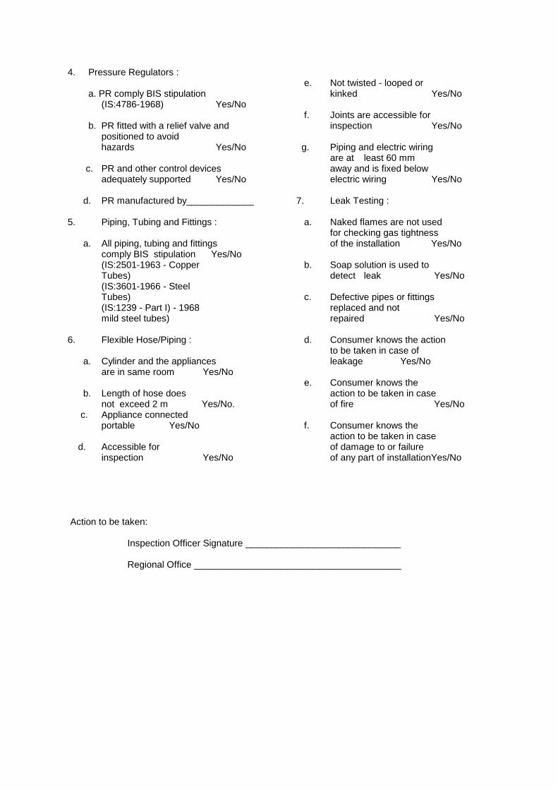
4. Pressure Regulators : a. PR comply BIS stipulation (IS:4786-1968) Yes/No b. PR fitted with a relief valve and positioned to avoid hazards Yes/No c. PR and other control devices adequately supported Yes/No d. PR manufactured by_____________ 5. Piping, Tubing and Fittings : a. All piping, tubing and fittings comply BIS stipulation Yes/No (IS:2501-1963 - Copper Tubes) (IS:3601-1966 - Steel Tubes) (IS:1239 - Part I) - 1968 mild steel tubes) 6. Flexible Hose/Piping : a. Cylinder and the appliances are in same room Yes/No b. Length of hose does not exceed 2 m Yes/No. c. Appliance connected portable Yes/No d. Accessible for inspection Yes/No
e. Not twisted - looped or kinked Yes/No f. Joints are accessible for inspection Yes/No g. Piping and electric wiring are at least 60 mm away and is fixed below electric wiring Yes/No 7. Leak Testing : a. Naked flames are not used for checking gas tightness of the installation Yes/No b. Soap solution is used to detect leak Yes/No c. Defective pipes or fittings replaced and not repaired Yes/No d. Consumer knows the action to be taken in case of leakage Yes/No e. Consumer knows the action to be taken in case of fire Yes/No f. Consumer knows the action to be taken in case of damage to or failure of any part of installationYes/No
Action to be taken:
Inspection Officer Signature ______________________________
Regional Office ________________________________________
<< Back Home Next >>