Embed Size (px)
DESCRIPTION
Dimensional
Citation preview
Material measures of length for general use.Part 2: Test methods
Mesures matérialisées de longueur pour usages généraux. Partie 2: Méthodes d'essais
OIM
L R 35-2 Edition 201
1 (E)
OIML R 35-2Edition 2011 (E)
ORGANISATION INTERNATIONALE
DE MÉTROLOGIE LÉGALE
INTERNATIONAL ORGANIZATION
OF LEGAL METROLOGY
INTERNATIONAL
RECOMMENDATION


OIML R 35-2: 2011 (E)
3
Contents
Foreword ................................................................................................................................................................. 4
1 Scope ............................................................................................................................................................ 5
2 Terminology ................................................................................................................................................. 5
3 Reference conditions .................................................................................................................................... 7
4 Unit of measurement .................................................................................................................................... 8
5 Documentation required ............................................................................................................................... 8 6 External examination .................................................................................................................................... 9 6.1 Object of examination .................................................................................................................................. 9 6.2 Examination procedures ............................................................................................................................... 9 7 Accuracy tests for all measures .................................................................................................................. 18 7.1 Description of equipment under test (EUT) ............................................................................................... 18 7.2 Requirements common to all tests .............................................................................................................. 18 7.3 Testing measures of length ......................................................................................................................... 20 7.4 Scale accuracy and large scale linearity ..................................................................................................... 20 7.5 Scale interval accuracy ............................................................................................................................... 22 7.6 Scale interval linearity ................................................................................................................................ 23 7.7 Accuracy of other metrological components .............................................................................................. 23 7.8 Accuracy tests for indicating devices ......................................................................................................... 24 8 Influence factor and disturbance tests for measures with ancillary electronic devices ............................... 26 8.1 Test conditions ........................................................................................................................................... 26 8.2 Climatic environment ................................................................................................................................. 26 8.3 Mechanical environment ............................................................................................................................ 27 8.4 Electromagnetic environment ..................................................................................................................... 27 8.5 Summary of influence factor and disturbance tests .................................................................................... 28 8.6 Static temperatures ..................................................................................................................................... 28 8.7 Damp heat, cyclic (condensing) ................................................................................................................. 30 8.8 Mechanical shock (drop test) ...................................................................................................................... 31 8.9 Radio-frequency immunity ......................................................................................................................... 32 8.10 Electrostatic discharge ................................................................................................................................ 34 8.11 Voltage of battery power source ................................................................................................................. 35
9 Test program for type approval .................................................................................................................. 37 9.1 Number of samples required....................................................................................................................... 37 9.2 Performance tests applicable to all material measures of length ................................................................ 37 9.3 Type approval of material measures of length fitted with electronic devices or separable parts ................ 37 10 Test program for initial verification ........................................................................................................... 38 10.1 Tests for initial verification ........................................................................................................................ 38 10.2 Initial verification of complete measures of length or ancillary devices .................................................... 39 11 Presentation of results................................................................................................................................. 40 11.1 Object of reports ......................................................................................................................................... 40 11.2 Identification and test data to be included in records ................................................................................. 40 Bibliography .......................................................................................................................................................... 42
OIML R 35-2: 2011 (E)
4
Foreword
The International Organization of Legal Metrology (OIML) is a worldwide, intergovernmental organization whose primary aim is to harmonize the regulations and metrological controls applied by the national metrological services, or related organizations, of its Member States. The main categories of OIML publications are:
International Recommendations (OIML R), which are model regulations that establish the metrological characteristics required of certain measuring instruments and which specify methods and equipment for checking their conformity. OIML Member States shall implement these Recommendations to the greatest possible extent;
International Documents (OIML D), which are informative in nature and which are intended to harmonize and improve work in the field of legal metrology;
International Guides (OIML G), which are also informative in nature and which are intended to give guidelines for the application of certain requirements to legal metrology; and
International Basic Publications (OIML B), which define the operating rules of the various OIML structures and systems.
OIML Draft Recommendations, Documents and Guides are developed by Project Groups linked to Technical Committees or Subcommittees which comprise representatives from OIML Member States. Certain international and regional institutions also participate on a consultation basis. Cooperative agreements have been established between the OIML and certain institutions, such as ISO and the IEC, with the objective of avoiding contradictory requirements. Consequently, manufacturers and users of measuring instruments, test laboratories, etc. may simultaneously apply OIML publications and those of other institutions.
International Recommendations, Documents, Guides and Basic Publications are published in English (E) and translated into French (F) and are subject to periodic revision.
Additionally, the OIML publishes or participates in the publication of Vocabularies (OIML V) and periodically commissions legal metrology experts to write Expert Reports (OIML E). Expert Reports are intended to provide information and advice, and are written solely from the viewpoint of their author, without the involvement of a Technical Committee or Subcommittee, nor that of the CIML. Thus, they do not necessarily represent the views of the OIML.
This publication - reference OIML R 35-2, edition 2011 (E) - was developed by the OIML Technical Subcommittee TC 7 Measuring instruments for length and associated quantities. It was approved for final publication by the International Committee of Legal Metrology at its 46th Meeting in Prague, Czech Republic in October 2011 and will be submitted to the International Conference of Legal Metrology in 2012 for formal sanction.
OIML Publications may be downloaded from the OIML web site in the form of PDF files. Additional information on OIML Publications may be obtained from the Organization’s headquarters:
Bureau International de Métrologie Légale 11, rue Turgot - 75009 Paris - France Telephone: 33 (0)1 48 78 12 82 Fax: 33 (0)1 42 82 17 27 E-mail: [email protected] Internet: www.oiml.org
OIML R 35-2: 2011 (E)
5
Material measures of length for general use
Part 2 – Test methods
1 Scope This Recommendation is applicable to the type evaluation and initial verification testing of material measures of length for general use, as defined in OIML R 35-1.
This Recommendation sets out details of the test program, principles, equipment and procedures to be used for type evaluation and initial verification testing.
2 Terminology Terms conform to the International Vocabulary of Metrology - Basic and general concepts and associated terms (VIM, edition 2007) [1] and to the International Vocabulary of Terms in Legal Metrology (VIML, edition 2000) [2].
In addition, for the purpose of this Recommendation, the terms and definitions given in R 35-1 also apply.
2.1 ancillary device device intended to perform a particular function, directly involved in elaborating, transmitting or displaying results
2.2 disturbance influence quantity having a value within specified limits but outside the specified rated operating conditions of the measure
2.3 durability ability of the measure to maintain its performance characteristics over a period of use
2.4 equipment under test (EUT) material measure of length; also referred to as the “measure”
2.5 error (of measurement) measured quantity value minus a reference quantity value [1 (VIM 2.16)]
2.6 fault difference between the error of indication and the intrinsic error of a measure
OIML R 35-2: 2011 (E)
6
2.7 indicating device part of the measure that indicates or displays the measuring result
2.8 influence factor influence quantity having a value within the specified rated operating conditions of the measure
2.9 influence quantity quantity which is not the subject of the measurement but which influences the value of the measurand or the indication of the measure [1 (adapted from VIM 2.52)]
2.10 intrinsic error error of a measure determined under reference conditions
Note: Principally a fault is the result of an undesired change of data contained in or flowing through an electronic measure.
2.11 performance ability of the measure to accomplish the intended functions
2.12 performance test test intended to verify whether the equipment under test is able to accomplish its intended functions
2.13 rated operating conditions conditions of use, giving the range of values of influence quantities for which the metrological characteristics are intended to lie within the specified permissible errors [1 (adapted from VIM 4.9)]
2.14 reference conditions set of specified values of influence factors fixed to ensure valid intercomparison of the results of measurements [1 (adapted from VIM 4.11)]
2.15 scale interval actual distance between the center-lines of two adjacent scale marks on the blade
OIML R 35-2: 2011 (E)
7
2.16 significant fault fault, the magnitude of which is greater than one-fifth of the magnitude of the maximum permitted error for the length measured
The following faults are considered not to be significant, even when they exceed the value defined above:
a) faults arising from simultaneous and mutually independent causes in the electronic device;
b) faults implying the impossibility to perform any measurement;
c) transitory faults being momentary variations in the indication, which cannot be interpreted, memorized or transmitted as a measurement result;
d) faults giving rise to variations in the measurement results so serious that they are bound to be noticed by all those interested in the result of the measurement.
2.17 supplementary device device intended to facilitate and extend the utility of the measure such as one or more fixed or movable hooks, rings, handles, tips, winding devices, and verniers
2.18 temperature stability temperature reached when all parts of the equipment under test are within 2 °C of each other
2.19 test series of operations intended to verify the compliance of the equipment under test with certain requirements
3 Reference conditions
3.1 The reference conditions are as shown below unless otherwise specified by the manufacturer and marked on the measure accordingly.
3.2 All applicable influence quantities, except for the influence quantity being tested, shall be held at the following values during type approval tests on a material measure of length. However, for influence factors and disturbances for measures with an electronic display, it is permissible to use the reference conditions defined in the applicable IEC standard:
Temperature: 20 °C or the temperature indicated on the measure. Tolerance ±2 °C
Ambient relative humidity range: 45 % to 75 %
Ambient atmospheric pressure: 86 kPa to 106 kPa pressure range: [0.86 bar to 1.06 bar]
Power source Ubmin ≤ Ub ≤ Ubmax range 3.3 During each test, the temperature and relative humidity shall not vary by more than 2 °C or 10 % respectively within the reference range.

OIML R 35-2: 2011 (E)
8
4 Unit of measurement The unit of length is the metre (symbol m) together with the authorized multiples and sub-multiples.
5 Documentation required
5.1 Documentation required for type approval The supplier shall submit one copy of the following documentation to the testing laboratory as well as the items to be tested, including an archival unit of the type tested (if requested by the testing laboratory).
5.1.1 Material measures of length without ancillary electronic devices
• Technical description o Model number o Accuracy class o Nominal length o Blade width o Case dimensions o Supplementary devices (hook, ring, etc), when applicable
• Material specifications o Blade material o Temperature coefficient of linear expansion
• Drawings/photographs
5.1.2 Material measures of length with ancillary electronic devices As above, and including:
• User’s manual/operating instructions • Installation instructions • Installation and security sealing plan • Software description, including protection • Climatic environment specification • Electromagnetic environment specification
5.2 Documentation required for initial verification The supplier shall make available data sheets with at least the following information:
5.2.1 Material measures of length without ancillary electronic devices
• Technical description • Type approval certificate
OIML R 35-2: 2011 (E)
9
5.2.2 Material measures of length with ancillary electronic devices As above, and including:
• User’s manual/operating instructions • Installation instructions • Type and specification of the power source • Security sealing plan • Software version number and how to read it • Test conditions for initial verification • Additional qualifying information supplied with the type approval certificate (e.g. additional
recommended test conditions)
6 External examination During the external examination, all the relevant values, dimensions and observations shall be recorded.
Note 1: For presentation of the results of type evaluation examinations, see section 10.
Note 2: For each examination task, the relevant subclauses of R 35-1 are shown in parentheses against it.
6.1 Object of examination To verify that the measure meets the requirements of R 35-1 with respect to the design, construction and markings.
6.2 Examination procedures The following aspects of the design shall be examined on at least one measure from the sample.
Either the same sample may be used for all the external examinations, or different measures from the samples submitted may be used for some of the examinations.
6.2.1 Nominal length (R 35-1, clause 5) 1) Verify that nominal length of the measure is an integral multiple of 0.5 m up to 15 m. Any nominal
length between 15 m and 100 m should be an integral multiple of 5 m, and any nominal length over 100 m should be an integral multiple of 50 m.
Note 1: Other values may be deemed appropriate for specific applications provided that the specific application is clearly indicated on the measure.
Note 2: Land surveying measures shall have nominal lengths of 5 m, 10 m, 20 m, 50 m, 100 m or 200 m.
2) Complete the section reference R 35-1, 5.1 – 5.3 in 5.1.1 of R 35-3.
6.2.2 Materials (R 35-1, clause 6) 1) Verify that the measure and its supplementary devices are made of materials which, under normal conditions of use, are sufficiently durable, stable, and resistant to environmental influences.
2) Verify that the properties of the materials used shall be such that:
OIML R 35-2: 2011 (E)
10
a) The maximum permissible error for the accuracy class to which the measure belongs shall not be exceeded by a change in temperature of ±8 °C about the reference temperature or the temperature indicated on the measure.
b) For measures which have to be used under a specified tension, a variation of ± 10 % of this tension
does not produce a variation in length exceeding the maximum permissible error. 3) Complete the section reference R 35-1, 6.1 – 6.2 in 5.1.1 of R 35-3.
6.2.3 Construction (R 35-1, clause 7) 1) Verify that the measure and its supplementary devices are well and robustly constructed, and carefully
finished.
2) Verify that the dimensions and shape of the cross-section of the measure are such that, under normal conditions of use, measurements can be made with the degree of accuracy required for the accuracy class to which the measure belongs.
3) Verify that tape measures are made in such a way that, when a tape is stretched out on a flat surface, its edges are virtually straight and parallel.
4) Verify that the surfaces forming the two principal scale marks (end surfaces) of end measures are flat and perpendicular to the longitudinal axis of the measure.
5) Verify that the end surfaces of an end or composite measure made of wood or other material of durability equal to or less than that of wood are provided with a bracket, plate, or end fitting which is resistant to wear and impact damage, and suitably attached to the measure.
6) Verify that any supplementary devices cannot cause confusion and that they are designed and attached to the measure in such a way that, under normal conditions of use, it is virtually impossible for the measurement uncertainty to be increased.
7) Verify that winding devices for tape measures are made in such a way that they do not cause any permanent deformation of the tape.
8) Complete the section reference R 35-1, 7.1 – 7.8 in 5.1.1 of R 35-3.
6.2.4 Scale (R 35-1, clause 8) 1) Verify that the scale is clear, regular, indelible, and carried out in such a way that reading is definite,
easy and unambiguous.
2) Verify that the scale interval is of the form:
1 × 10n, 2 × 10n or 5 × 10n m,
Where: n is a positive or negative whole number or zero.
3) Verify that the scale interval does not exceed:
a) 1 mm for measures with a nominal length of 0.5 m or 1 m, in relation to their accuracy,
b) 1 cm for measures with a nominal length not greater than 2 m,
c) 10 cm if the nominal length is greater than 2 m and less than 10 m,
OIML R 35-2: 2011 (E)
11
d) 20 cm if the nominal length is equal to or greater than 10 m and less than 50 m,
e) 50 cm if the nominal length is equal to or greater than 50 m.
Note: These values may be exceeded for specific applications, provided the specific application is indicated on the measure.
4) When the scale marks are lines, verify that:
a) These are straight, perpendicular to the axis of the measure, and all have the same width, which is constant throughout their length.
b) The length of the lines is related to the corresponding unit of measurement. The lines shall be such that they form a distinct and clear scale and that their width does not cause any measurement uncertainty.
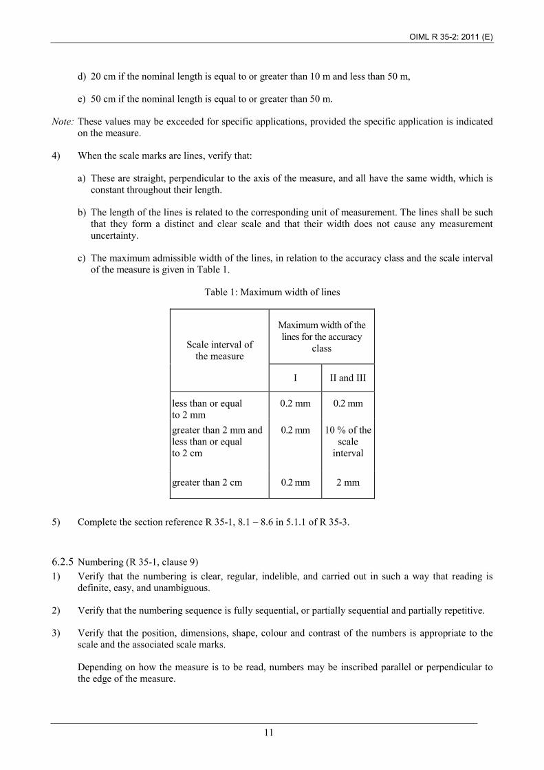
c) The maximum admissible width of the lines, in relation to the accuracy class and the scale interval of the measure is given in Table 1.
Table 1: Maximum width of lines
Scale interval of the measure
Maximum width of the lines for the accuracy
class
I II and III
less than or equal to 2 mm
0.2 mm
0.2 mm
greater than 2 mm and less than or equal to 2 cm
0.2 mm
10 % of the scale
interval
greater than 2 cm
0.2 mm
2 mm
5) Complete the section reference R 35-1, 8.1 – 8.6 in 5.1.1 of R 35-3.
6.2.5 Numbering (R 35-1, clause 9) 1) Verify that the numbering is clear, regular, indelible, and carried out in such a way that reading is
definite, easy, and unambiguous.
2) Verify that the numbering sequence is fully sequential, or partially sequential and partially repetitive.
3) Verify that the position, dimensions, shape, colour and contrast of the numbers is appropriate to the scale and the associated scale marks.
Depending on how the measure is to be read, numbers may be inscribed parallel or perpendicular to the edge of the measure.
OIML R 35-2: 2011 (E)
12
4) Verify that the numbers representing millimetres, centimetres, decimetres, or metres are not accompanied by the corresponding symbols.
Note 1: If the numbered unit is not the metre, the scale marks corresponding to metres may be numbered in metres, in which case these numbers shall be followed by the symbol “m”. The number of preceding metres may be repeated in the same way in front of the other numbered scale marks.
Note 2: Millimetre scales shall be numbered every centimetre.
Note 3: When the scale interval of a line measure is in the form of 2 × 10n and not less than 2 cm, all scale marks shall be numbered.
5) Complete the section reference R 35-1, 9.1 – 9.5 in 5.1.1 of R 35-3.
6.2.6 Inscriptions (R 35-1, clause 10) 1) Verify that the measure is clearly and indelibly marked with the following information, either placed
at the beginning of the measure or on the case of the measure if the case and measure are not separable:
a) Nominal length (optional in a rectangle);
b) The numeric code, trade mark or trade name of the manufacturer and/or of his representative;
c) The designation of accuracy class: I, II, or III in an oval;
d) The reference temperature, if other than 20 °C;
e) The tension, if specified;
f) The specific use for which the measure is intended, in the cases covered by R 35-1, 5.2 (nominal length) and R 35-1, 8.2 (scale interval).
2) Complete the section reference R 35-1, 10.1 – 10.8 in 5.1.1 of R 35-3.
6.2.7 Indicating device (R 35-1, clause 11) Applicable to material measures of length with an electrically powered digital readout
1) Verify that the indicating device of the measure provides an easily read, reliable and unambiguous visual indication of the indicated length.
2) Verify that the indicating device can display the indicated length up to and including the nominal length of the measure.
3) Verify that the indicated length is expressed in metres (symbol m) or authorized multiples and sub-multiples and that the appropriate symbol appears immediately adjacent to the numbered display.
4) The indicated length is given by a line of adjacent digits appearing in one or more apertures. Verify that the advance of a given digit is completed while the digit of the next immediately lower decade changes from 9 to 0.
5) Verify that the length displayed on the indicating device agrees with the measurement made by the blade to the nearest scale interval of the blade.
OIML R 35-2: 2011 (E)
13
6) Verify that there is no ambiguity in distinguishing between the primary indication and alternative displays.
7) Verify that on switch-on and optionally on demand, it shall be possible to visually check the correct operation of the entire display.
8) Complete the section reference R 35-1, 11.1.1 – 11.2.2 in 5.1.1 of R 35-3.
6.2.8 Verification (or control) marks (R 35-1, clause 13) 1) Verify that the measure is constructed so that it may accommodate the verification (or control) marks,
prescribed by national regulations, near the beginning of the measure.
2) Complete the section reference R 35-1, 13 in 5.1.1 of R 35-3.
A – Measures for short lengths
6.2.9 Semi-rigid steel tape measure in a case (R 35-1, clause 14) 1) Verify that the measure has nominal lengths between 0.5 m and 15 m. 2) Verify that the measure is of the end, line, or composite type. 3) Verify whether or not the end-ring is included in the nominal length. 4) If a supplementary device is fastened to the end of a measure, verify that any obscuration of the scale
marks occurs only under the conditions specified in R 35-1, 14.2.2. 5) Verify that for a measure contained in a case that is designed to be part of the range of the scale:
a) The zero end of the blade is of the end type and is provided with a fixed or sliding hook or tongue. b) The belt clip or carrying strap do not obscure any dimensions marked on the side of the case or
interfere with internal measurements. 6) Verify that the blade lock is strong enough to hold the blade at all extensions up to and including fully
extended. 7) Verify that cross-section of the blade is cambered. 8) Verify that if the measure has two scales on the same face, they have the same point of origin. 9) Verify that the scale interval is less than or equal to 1 cm. 10) Verify that the measure conforms to accuracy class I or II. 11) Complete the section reference R 35-1, 14.1 – 14.4 in 5.1.1 of R 35-3.

OIML R 35-2: 2011 (E)
14
6.2.10 Semi-rigid steel tape measure with digital readout(R 35-1, clause 15) 1) Verify that the measure meets the requirements given in 6.2.9 above, and in addition: 2) Verify that the power source compartment forms an integral part of the measure. 3) Complete the section reference R 35-1, 15.1 – 15.5 in 5.1.1 of R 35-3.
6.2.11 One-piece rigid or semi-rigid measure (R 35-1, clause 16) 1) Verify that the measure has nominal lengths between 0.5 m and 5 m. 2) Verify that the measure is of the end, line, or composite type. 3) Verify that the measure is made of metal or other suitable materials. 4) Verify that if the zero scale mark of a dipstick is its end, this end is provided with an impact and wear
resistant heel or tip made of a material not liable to cause sparking on impact. 5) Verify that the measure conforms to accuracy class I or II. 6) Complete the section reference R 35-1, 16.1 – 16.4 in 5.1.1 of R 35-3.
6.2.12 Flexible tape measure made of fibreglass and plastics or other suitable non-metallic materials (R 35-1 clause 17)
1) Verify that the measure has nominal lengths between 0.5 m and 5 m. 2) Verify that the measure is of the end, line, or composite type. 3) Verify that the free ends of an end or composite measure are provided with wear-resistant bands or tips
which are firmly attached to the tape 4) Verify whether or not the end-ring is included in the nominal length. 5) Verify that specified tension is approximately 10 N to 20 N and is indicated on the measure. 6) Verify that on a line measure, the zero scale mark is located at a distance of at least 20 mm from the
nearest end of the measure if the latter is not fitted with a ring or from the outer edge of the ring if it is fitted with a ring.
7) Verify that the measure conforms to accuracy class I, II or III. 8) Complete the section reference R 35-1, 17.1 – 17.3 in 5.1.1 of R 35-3.
OIML R 35-2: 2011 (E)
15
6.2.13 Folding measure made of metal or other materials (R 35-1, clause 18) 1) Verify that the measure has nominal lengths between 0.5 m and 5 m. 2) Verify that the measure is of the end type. 3) Verify that all parts which are jointed at both ends have the same length between their jointing axes. 4) Verify that the jointing and alignment of the unfolded measure is ensured by an effective device. 5) Verify that the total additional error due to the jointing and alignment does not exceed the limits given
in R 35-1, 18.2.2. 6) Verify that the measure conforms to accuracy class II or III. Class I is also permissible for screw-
assembly type jointed measures. 7) Complete the section reference R 35-1, 18.1 – 18.4 in 5.1.1 of R 35-3.
6.2.14 Telescopic measure made of metal or other materials (R 35-1, clause 19) 1) Verify that the measure has nominal lengths between 0.5 m and 5 m. 2) Verify that the measure is of the end type. 3) Verify that the jointing and alignment of the unfolded measure is ensured by an effective device. 4) Verify that the total additional error due to the jointing and alignment does not exceed the limits given
in R 35-1, 19.2.1. 5) Verify that the measure is made of metal or other suitable materials. 6) Verify that the terminal surface of the measure is flat and perpendicular to the longitudinal axis of the
measure 7) Verify that the end of the measure is provided with an impact and wear resistant heel or tip made of a
material not liable to cause sparking on impact. 8) Verify that a measure which is circular in cross-section has only one scale along its length.
9) Verify that the measure conforms to accuracy class II or III.
10) Complete the section reference R 35-1, 19.1 – 19.4 in 5.1.1 of R 35-3.
6.2.15 Telescopic measures made of metal or other materials with digital readout (R 35-1, clause 20) 1) Verify that the measure meets the requirements given in 6.2.14 above, and in addition: 2) Verify that the power source compartment forms an integral part of the measure. 3) Complete the section reference R 35-1, 20.1 – 20.5.1in 5.1.1 of R 35-3.
OIML R 35-2: 2011 (E)
16
B – Measures for long lengths
6.2.16 Flexible steel tape measure with winding device not designed for measuring lengths greater than its nominal length by repeated use of the same tape (R 35-1, clause 21)
1) Verify that the measure has nominal lengths between 5 m and 200 m. 2) Verify that the measure is of the line or composite type. 3) Verify that for a measure in class I, the free end is provided with a handle or ring, which is not
included in the nominal length. 4) Verify that for a measure in class II, the free end is provided with a handle or ring which may be
included in the nominal length and if so, that the beginning of the scale is clearly indicated. 5) If a supplementary device is fastened to the end of a measure, verify that any obscuration of the scale
marks occurs only under the conditions specified in R 35-1, 21.2.2. 6) Verify that the specified tension is approximately 50 N or greater and is indicated on the measure. 7) Verify that the reference temperature, if other than 20 °C, is indicated on the measure. 8) Verify that the measure conforms to accuracy class I or II. 9) Complete the section reference R 35-1, 21.1 – 21.4 in 5.1.1 of R 35-3.
6.2.17 Flexible steel tape measures with tensioning weight or sinker (R 35-1, clause 22) 1) Verify that the measure has nominal lengths between 5 m and 50 m. 2) Verify that the measure is of the composite type. 3) Verify that the mass of the sinker is indicated to within ±10 g, on both measure and sinker. 4) Verify that the sinker has a sufficient mass to stretch out the tape properly and that it is made of a
material not liable to cause sparking on impact. 5) Verify that the sinker attachment or joint is such that additional measurement uncertainty is
minimized. 6) Verify that:
a) The scale is regular, with a scale interval of 1 mm. b) The base of the sinker constitutes the principal scale mark at the zero end of the scale. c) The scale starts on a flat face of the sinker and continues along the entire length of the tape.
7) Verify that the measure conforms to accuracy class I or II. 8) Complete the section reference R 35-1, 22.1 – 22.5 in 5.1.1 of R 35-3.

OIML R 35-2: 2011 (E)
17
6.2.18 Flexible steel tape measure with tensioning weight or sinker equipped with electronic sensing (R 35-1, clause 23)
1) Verify that the measure meets the requirements given in 6.2.17 above. The requirement in 6.2.17 5)
may have to be adapted according to how the electronic sensing device is attached. In addition: 2) Verify that the sensing element of the measure provides a clear and reliable indication of the air/oil
and oil/water phase transition. 3) Verify that the battery compartment forms an integral part of the measure. 4) Verify that the measure conforms to accuracy class I or II. 5) Complete the section reference R 35-1, 23.1 – 23.7 in 5.1.1 of R 35-3.
6.2.19 Flexible steel surveyor's tapes designed for measuring lengths greater than their nominal length by repeated use of the same tape (R 35-1, clause 24)
1) Verify that the measure has a nominal length of 5 m, 10 m, 20 m, 50 m, 100 m, or 200 m. 2) Verify that the measure is of the end or line type. 3) Verify that the specified tension is approximately 50 N or greater and is indicated on the measure. 4) Verify that if the handles are included in the nominal length, they are so constructed that their
attachment to the tape introduces no uncertainty of measurement. 5) Verify that the measure conforms to accuracy class I or II. 6) Complete the section reference R 35-1, 24.1 – 24.4 in 5.1.1 of R 35-3.
6.2.20 Flexible tape measures made of fibreglass and plastics or other suitable non-metallic materials (R 35-1, clause 25)
1) Verify that the measure has a nominal length between 5 m and 100 m. 2) Verify that the measure is of the end, line or composite type. 3) Verify that the ends of an end measure and the zero end of a composite measure are provided with
wear-resistant bands or tips which are firmly attached to the tape. 4) Verify that the ring on the free end of a measure in class I is not included in the nominal length. 5) Verify whether or not the ring on the free end of a measure in classes II and III is included in the
nominal length. If so, verify that the beginning of the scale is clearly indicated. 6) If a supplementary device is fastened to the end of a measure, verify that any obscuration of the scale
marks occurs only under the conditions specified in R 35-1, 25.2.3. 7) Verify that the specified tension is approximately 10 N to 20 N, and that it is indicated on the measure.

OIML R 35-2: 2011 (E)
18
8) Verify that the measure conforms to accuracy class I, II or III. 9) Complete the section reference R 35-1, 25.1 – 25.4 in 5.1.1 of R 35-3.
7 Accuracy tests for all measures During the performance tests, all the relevant values, dimensions and observations shall be recorded.
Note 1: For presentation of the results of type evaluation or verification tests, see 11 below.
Note 2: The relevant subclauses of R 35-1 are shown in parentheses below.
7.1 Description of equipment under test (EUT) (R 35-1, 2.2) For the purpose of testing, the EUT shall be described by: a) Category, e.g. semi-rigid steel tape measure in a case.
b) Sub-category, e.g. composite measure.
7.2 Requirements common to all tests
7.2.1 Test equipment 1) Measurements shall be made using traceable, calibrated measuring devices.
2) Test equipment shall be so designed, constructed and used, that the performance of the equipment itself shall not contribute significantly to the test error. To this end, high standards of equipment maintenance are necessary.
3) The test environment shall be such that the reference conditions of the test are met (see clause 3).
4) It shall be possible to carry out test readings rapidly and easily.
7.2.2 Location The environment chosen for the tests shall be in accordance with the principles elaborated in OIML G 13 Planning of metrology and testing laboratories [3] and shall be free from disturbing influences (for example, ambient temperature, vibration).
7.2.3 Handling 1) Every measure submitted must first be inspected to ensure that its material, form and condition are
adequate for the class of accuracy specified.
2) High quality measures should never be handled with bare hands. Where handling equipment is not supplied they may be handled with clean gloves made of chamois leather or other appropriate material.

OIML R 35-2: 2011 (E)
19
7.2.4 Preparation 1) Rigid and semi-rigid line measures are usually boxed and should be kept in their boxes for safekeeping
until inspection and testing are carried out.
2) Flexible line measures are easily kinked and damaged and care should be taken when handling them.
Flexible line measures are calibrated under a specific tension (usually specified on the measure).
Care must be taken to even out the tension along the tape. 3) Folding and telescopic line measures are usually boxed and should be kept in their boxes for
safekeeping until inspection and testing are carried out.
Care should be taken to ensure that the measures are fully extended, paying particular attention to the joints.
4) To ensure a submitted measure has come to thermal equilibrium with the laboratory it should be kept in the testing laboratory for at least 12 hours (usually overnight) prior to commencement of inspection and test. The measure should also be stretched out on the measurement bench for at least 2 hours to ensure it has reached thermal equilibrium at the point of test; a period of 4 hours is recommended for Class 1 accuracy measures.
7.2.5 Ambient conditions 1) The ambient conditions should be checked and testing should only be commenced if the conditions are
within the range specified by the manufacturer or test laboratory or by the applicable IEC standard.
7.2.6 Temperature compensation 1) If necessary the measuring procedure can be adapted to make corrections to reduce the result to a
standard reference temperature.
2) Contact thermometer probes should be affixed to the measure at suitable intervals along its length. The average material temperature is calculated by taking the arithmetic mean of all the results from the temperature probes used.
3) The average material temperature is used to correct the measured length to the reference temperature by using the linear thermal expansion coefficient in the following formula:
Lc = Lm [1 + α ( Tr – Tm )] where:
Lc = corrected length, Lm = measured length, α = linear thermal expansion coefficient, Tr = reference temperature, Tm = average material temperature.
The error from nominal is calculated by subtracting the nominal length from the corrected length.
7.2.7 Mechanical environment Mechanical tests are required to determine the robustness of the blade, case or ancillary electronic device if dropped onto a hard surface. These tests are not required for permanently-installed measures.
OIML R 35-2: 2011 (E)
20
7.3 Testing measures of length
7.3.1 Object of the tests To determine if the measure is linear and accurate throughout its length within the limits of the mpe for the accuracy class specified.
7.3.2 Types of test At five different places randomly distributed over the measure of length, but including the nominal length, a check shall be made of:
a) Scale accuracy and large scale linearity, i.e. the distance between two non-consecutive marks at various points along the length of the measure, one of which is always zero.
b) Scale interval accuracy, i.e. the length of the scale interval at various points along the length of the measure.
c) Scale interval linearity, i.e. the difference between the lengths of two consecutive scale intervals at various points along the length of the measure.
d) Accuracy of other metrological components to the measure, such as hooks, rings, dimensioned cases, detachable sinkers. Note: for sliding hooks, the maximum sliding distance is commonly made equal to the hook thickness; fixed hooks are commonly thin enough to meet the MPE requirements for both internal and external measurements.
7.4 Scale accuracy and large scale linearity (R 35-1, 26.2.2) Large scale linearity and accuracy tests are carried out as described below. There is no reference to standards for this test. Object of the test: To determine if the measure is linear and accurate throughout its length
within the limits of the mpe for the accuracy class specified.
Scope: This procedure applies to all material measures, be they rigid, semi-rigid, flexible, folding or telescopic, and includes measures of various cross sections and nominal lengths.
Test procedures in brief Precondition: Tape measures shall be stretched out over their total length on a
horizontal surface, practically without friction, under the specified tension.
Test severity: Apply mpe criteria according to the accuracy class of the EUT.
Stabilization: Before any test, stabilize the EUT for at least 2 hours under the specified
environmental conditions [see 7.2.4 4)].
Length measuring test: Secure the EUT onto the test bench adjacent to the test equipment.
Affix the thermometer probes along the measure, if required, (R 35-2, 7.2.6).
OIML R 35-2: 2011 (E)
21
Measure the distances of A1, A2, A3, B1, B2, B3, etc, to E3 from O as shown in Figure 1, where:
a) O is the origin of the measure
b) A, B, C, D are randomly selected points along the measure
c) Suffices 1 and 2 represent consecutive scale marks
d) E3 is the nominal length
Record these measurements in R 35-3, 6.1
Also record:
a) Date and time
b) Temperature
c) Tension (if applicable)
Complete test report 6.2 in R 35-3.
The error for each of the points A, B, C, D and E2 is calculated by subtracting the reading on the EUT, e.g. A, (corrected for temperature, if necessary) from the value of length measured by the test equipment.
Calculate the maximum permissible errors for the points A, B, C, D and E3. Use the equation in R 35-1 4.2.1. For lengths less than 1 m, the value of L in the equation is made equal to 1.0. Some categories of measure may require corrections to be made to the intrinsic error or have conditions attaching to the mpe. These are:
a) End or composite measures, R 35-1, 4.2.4 refers.
b) Folding measures, R 35-1, 18.2.2 refers.
c) Telescopic measures, R 35-1, 19.2.1 refers.
d) Flexible steel tape measures with tensioning weight or sinker, R 35-1, 22.5 refers.
Verify that the error is less than or equal to the mpe for the specified accuracy class.
Number of test cycles: One for each scale (telescopic measures, for example, could have more
than one scale).

OIML R 35-2: 2011 (E)
22
7.5 Scale interval accuracy (R 35-1, 26.2.3) Short scale accuracy tests are carried out as described below. There is no reference to standards for this test. Object of the test: To determine if the length of the scale interval is accurate throughout the
length of the measure within the limits of the mpe for the accuracy class specified.
Scope: This procedure applies to all material measures, be they rigid, semi-rigid, flexible, folding or telescopic, and includes measures of various cross sections and nominal lengths.
Test procedures in brief: Use the results obtained in the large scale linearity and accuracy tests in 6.3 above and complete the test report 6.3 in R 35-3.
Calculate the scale intervals at each of the points A to E, e.g. subtract length OA1from length OA, OA2 from OA1, etc. The error for each of the scale intervals is calculated by subtracting the nominal value of the interval, e.g. 1 mm, from the value measured by the test equipment (corrected for temperature, if necessary).
Compare these with the mpes in R 35-1:
a) Use Table 2 if the scale interval is less than or equal to 1 cm. b) Use the equation in 4.2.2 if the scale interval is greater than 1 cm.
Verify that the error is less than or equal to the mpe for the specified accuracy class.
O A1-A3 B1-B3 C1-C3 D1-D3 E1-E3
Figure 1: Schematic of selected test points on a measure of length. Not to scale
C1 C2 C3
Magnified view
Origin Nominal length
OIML R 35-2: 2011 (E)
23
7.6 Scale interval linearity (R 35-1, 26.2.4) Short scale linearity tests are carried out as described below. There is no reference to standards for this test. Object of the test: To determine if the difference between the lengths of two consecutive
scale intervals is accurate throughout the length of the measure within the limits of the mpe for the accuracy class specified.
Scope: This procedure applies to all material measures, be they rigid, semi-rigid, flexible, folding or telescopic, and includes measures of various cross sections and nominal lengths.
Test procedures in brief: Use the values of the scale intervals obtained in the short scale accuracy
tests in 6.4 above and complete the test report 6.4 in R 35-3.
Calculate the difference between the values of the consecutive scale intervals at each of the points A to E. Note: scale interval linearity cannot be calculated when one of the scale intervals is a terminal scale division bounded by an end surface (R 35-1, 4.2.4 refers).
Compare these differences with the maximum permissible differences shown in Table 3 in R 35-1, 4.2.3.
Verify that the measured difference is less than or equal to the maximum permissible difference for the specified accuracy class.
7.7 Accuracy of other metrological components (R 35-1, 26.2.5) Tests on other metrological components are carried out as described below. There is no reference to standards for this test. Object of the test: To determine if the dimensions of the components meet the mpe
requirements.
Scope: This procedure applies to components of the measure that carry dimensions. Examples are cases for semi-rigid steel tape measures and detachable tensioning sinkers for flexible steel tape measures.
Test procedures in brief: The test equipment may comprise:
a) gauge blocks or similar, to measure tape case dimensions;
b) tape bench to measure the effect of end-hooks and rings;
c) tape bench or callipers to measure sinkers.
Secure the EUT onto the test bench adjacent to the test equipment.
Measure the length of the EUT.
OIML R 35-2: 2011 (E)
24
Record:
a) Date and time;
b) Temperature;
c) Length.
Complete test report 6.5 in R 35-3.
Verify that the mpe meets the requirements for a nominal length of measure less than 1 m. No additional corrections for the ends are required.
7.8 Accuracy tests for indicating devices
7.8.1 Agreement with blade reading (R 35-1, 27.2.1) Tests on the indicating device are carried out as described below. There is no reference to standards for this test. Object of the test: To determine if the displayed indication agrees with the measurement
made by the blade.
Scope: This procedure applies to measures fitted with indicating devices.
Test procedures in brief:
Precondition: Measures shall be placed on a horizontal surface, practically without friction, under the specified tension.
Test severity: N/A
Stabilization: Before any test, stabilize the EUT for at least 2 hours under the specified
environmental conditions [see 7.2.4 4)].
Indication agreement test: Secure the EUT onto the test bench adjacent to the test equipment.
Starting at zero, extend the blade of the EUT to four randomly chosen extensions and to the nominal length.
Record:
a) Date and time;
b) Temperature;
c) Length;
d) Extension of blade, including zero;
e) Reading on indicating device.
Complete test report 6.6.1 in R 35-3.
Verify that the length indicated on the display agrees with the measurement made by the blade to the nearest scale interval of the blade. (R 35-1, 11.1.6).
OIML R 35-2: 2011 (E)
25
7.8.2 Hysteresis (R35-1, 27.2.2) Tests on the indicating device are carried out as described below. There is no reference to standards for this test. Object of the test: To determine if the displayed indication agrees with the direct reading on
the blade for a change in blade extension of one scale interval.
Scope: This procedure applies to measures fitted with indicating devices.
Test procedures in brief:
Precondition: Measures shall be placed on a horizontal surface, practically without friction, under the specified tension.
Test severity: N/A
Stabilization: Before any test, stabilize the EUT for at least 2 hours under the specified
environmental conditions [see 7.2.4 4)].
Indication agreement test: Secure the EUT onto the test bench adjacent to the test equipment.
Extend the blade of the EUT to a randomly chosen position. Record the blade extension and the reading on the indicating device. Extend the blade by one scale interval and record the readings. Contract the blade extension by one scale interval and record the readings. Repeat for two other randomly chosen extensions.
Record:
a) Date and time;
b) Temperature;
c) Length;
d) Extension of blade;
e) Reading on indicating device.
Complete test report 6.6.2 in R 35-3.
Verify that the length indicated on the display increments and decrements in agreement with the blade extension (R 35-1, 11.1.6).
OIML R 35-2: 2011 (E)
26
8 Influence factor and disturbance tests for measures with ancillary electronic devices
8.1 Test conditions
8.1.1 General requirements 8.1.1.1 Influence factor and disturbance tests specified in R 35-1, 27.5 are intended to verify that electronic devices fitted to material measures of length can perform and function as intended in the environment and under the conditions specified. Each test indicates, where appropriate, the reference condition under which the intrinsic error is determined. 8.1.1.2 When the effect of one influence factor is being evaluated, all other factors are to be held relatively constant, at a value close to normal. After each test the instrument shall be allowed to recover sufficiently before the following test. Where parts of the measuring instrument are examined separately, errors shall be apportioned in accordance with details given in the appropriate test below. 8.1.1.3 The operational status of the EUT or simulator shall be recorded for each test. 8.1.1.4 The applicant for type approval may define specific environmental conditions for the intended use of the instrument in the documentation supplied to the metrological authority. In this case the metrological authority carries out the tests at severity levels corresponding to these specific environmental conditions. If type approval is granted the data plate or accompanying instructions shall indicate the corresponding limits of uses. Conditions of use for which the instrument is to be approved shall be provided by the manufacturer. The metrological authority shall verify that the conditions of use are met. 8.1.1.5 When the EUT is connected in other than a normal configuration, the procedure shall be mutually agreed on by the approving authority and the applicant.
8.1.2 Simulated requirements
8.1.2.1 General The simulator for influence factor and disturbance tests should include all electronic devices of the measuring system, as appropriate.
8.1.2.2 Documentation Simulators shall be defined in terms of hardware and functionality by reference to the instrument under test and by any other documentation necessary to ensure reproducible test conditions. This information shall be attached to, or be traceable from the test report.
8.2 Climatic environment
8.2.1 Temperature Because measures can be used indoors or outdoors, the choice of the lower and upper temperature severity levels (R 35-1, 27.5.1) is left to national (or regional) legislation. In the absence of such legislation, the limits shall be declared by the manufacturer.
OIML R 35-2: 2011 (E)
27
8.2.2 Humidity The choice of severity levels (1 or 2) for cyclic damp heat tests (R 35-1, 27.5.2) is left to national (or regional) legislation. In the absence of such legislation, the level shall be declared by the manufacturer as befitted by the description below.
Severity level Description
1
This level applies to instruments or parts of instruments used in enclosed locations whose humidity is not controlled. Measuring instruments may be subject to condensed water, water from sources other than rain and to ice formations. The conditions of this class may be found in some entrances and staircases of buildings, in garages, cellars, certain workshops, factory buildings and industrial process plants, ordinary storage rooms for frost-resistant products, farm buildings, etc.
2 This level applies to instruments or parts of instruments used in open locations with average climatic conditions, thus excluding polar and desert environments.
8.3 Mechanical environment Portable measures of length, particularly those with ancillary electronic devices, should be capable of withstanding being dropped onto a hard surface from a height of 0.75 m.
8.4 Electromagnetic environment The electromagnetic environment for influence and disturbance tests may be classified as follows:
a) Class E1 - This class applies to instruments used in locations with electromagnetic disturbances corresponding to those likely to be found in residential, commercial and light industrial buildings.
b) Class E2 - This class applies to instruments used in locations with electromagnetic disturbances
corresponding to those likely to be found in industrial buildings.
OIML R 35-2: 2011 (E)
28
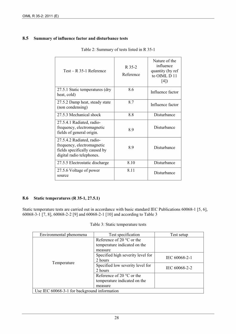
8.5 Summary of influence factor and disturbance tests
Table 2: Summary of tests listed in R 35-1
Test – R 35-1 Reference
R 35-2
Reference
Nature of the influence
quantity (by ref to OIML D 11
[4])
27.5.1 Static temperatures (dry heat, cold)
8.6 Influence factor
27.5.2 Damp heat, steady state (non condensing)
8.7 Influence factor
27.5.3 Mechanical shock 8.8 Disturbance
27.5.4.1 Radiated, radio-frequency, electromagnetic fields of general origin.
8.9 Disturbance
27.5.4.2 Radiated, radio-frequency, electromagnetic fields specifically caused by digital radio telephones.
8.9 Disturbance
27.5.5 Electrostatic discharge 8.10 Disturbance
27.5.6 Voltage of power source
8.11 Disturbance
8.6 Static temperatures (R 35-1, 27.5.1) Static temperature tests are carried out in accordance with basic standard IEC Publications 60068-1 [5, 6], 60068-3-1 [7, 8], 60068-2-2 [9] and 60068-2-1 [10] and according to Table 3
Table 3: Static temperature tests
Environmental phenomena Test specification Test setup
Temperature
Reference of 20 °C or the temperature indicated on the measure
Specified high severity level for 2 hours IEC 60068-2-1
Specified low severity level for 2 hours IEC 60068-2-2
Reference of 20 °C or the temperature indicated on the measure
Use IEC 60068-3-1 for background information
OIML R 35-2: 2011 (E)
29
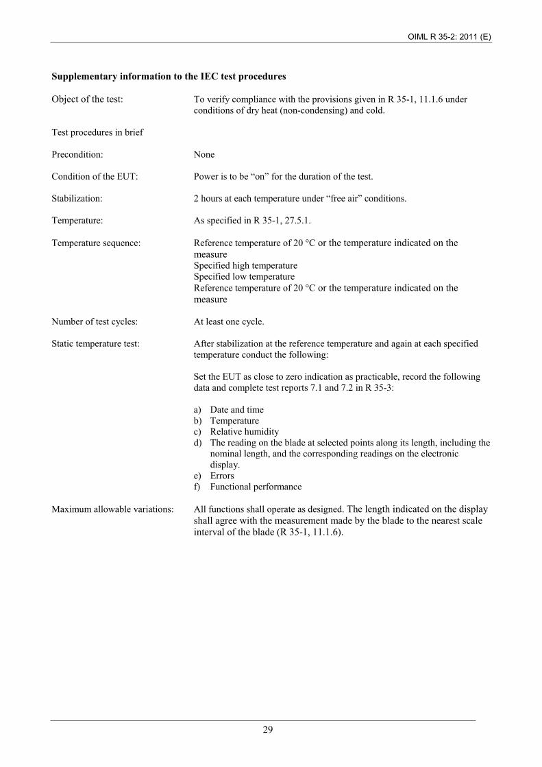
Supplementary information to the IEC test procedures Object of the test: To verify compliance with the provisions given in R 35-1, 11.1.6 under
conditions of dry heat (non-condensing) and cold. Test procedures in brief Precondition: None Condition of the EUT: Power is to be “on” for the duration of the test. Stabilization: 2 hours at each temperature under “free air” conditions. Temperature: As specified in R 35-1, 27.5.1. Temperature sequence: Reference temperature of 20 °C or the temperature indicated on the
measure Specified high temperature Specified low temperature Reference temperature of 20 °C or the temperature indicated on the measure
Number of test cycles: At least one cycle. Static temperature test: After stabilization at the reference temperature and again at each specified
temperature conduct the following:
Set the EUT as close to zero indication as practicable, record the following data and complete test reports 7.1 and 7.2 in R 35-3: a) Date and time b) Temperature c) Relative humidity d) The reading on the blade at selected points along its length, including the
nominal length, and the corresponding readings on the electronic display.
e) Errors f) Functional performance
Maximum allowable variations: All functions shall operate as designed. The length indicated on the display
shall agree with the measurement made by the blade to the nearest scale interval of the blade (R 35-1, 11.1.6).

OIML R 35-2: 2011 (E)
30
8.7 Damp heat, cyclic (condensing) (R 35-1, 27.5.2) Damp heat, cyclic tests are carried out in accordance with basic standard IEC Publications 60068-3-4 [11], and 60068-2-30 [12] and according to Table 4
Table 4: Damp heat, cyclic tests
Environmental phenomena Test specification Test setup
Damp heat, cyclic
Lower temperature 25 °C
IEC 60068-2-30
Upper temperature Specified severity level Relative humidity ≥ 93 % Period of cycle 12 h + 12 h Number of cycles 2 Recovery period before proceeding to the next test
min. 1 h max. 1 h
Use IEC 60068-3-4 for background information and IEC 60068-2-30 for specific parts of the test. Supplementary information to the IEC test procedures Object of the test: To verify compliance with the provisions given in R 35-1, 11.1.6 under
conditions of cyclic, damp heat. Test procedures in brief Precondition: None. Set the EUT as close to zero indication as practicable, prior to the
test. Condition of the EUT: Power is to be “on” for the duration of the test. Temperature sequence: As specified in Table 4.
Condensation shall occur on the EUT during the temperature rise. Number of test cycles: 2 cycles. Damp heat test: At the end of the recovery time after each cycle, conduct the following:
Set the EUT as close to zero indication as practicable, record the following data and complete test report 7.3 in R 35-3: a) Date and time b) Temperature c) Relative humidity d) The reading on the blade at selected points along its length, including
the nominal length, and the corresponding readings on the electronic display.
e) Errors f) Functional performance
Maximum allowable variations: All functions shall operate as designed. The length indicated on the
display shall agree with the measurement made by the blade to the nearest scale interval of the blade (R 35-1, 11.1.6).
OIML R 35-2: 2011 (E)
31
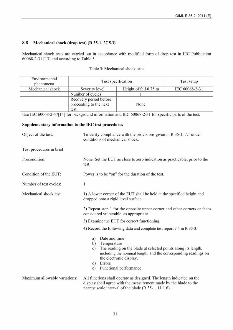
8.8 Mechanical shock (drop test) (R 35-1, 27.5.3) Mechanical shock tests are carried out in accordance with modified form of drop test in IEC Publication 60068-2-31 [13] and according to Table 5.
Table 5: Mechanical shock tests
Environmental phenomena Test specification Test setup
Mechanical shock Severity level Height of fall 0.75 m IEC 60068-2-31 Number of cycles 1 Recovery period before
proceeding to the next test
None
Use IEC 60068-2-47[14] for background information and IEC 60068-2-31 for specific parts of the test. Supplementary information to the IEC test procedures Object of the test: To verify compliance with the provisions given in R 35-1, 7.1 under
conditions of mechanical shock. Test procedures in brief Precondition: None. Set the EUT as close to zero indication as practicable, prior to the
test. Condition of the EUT: Power is to be “on” for the duration of the test. Number of test cycles: 1 Mechanical shock test: 1) A lower corner of the EUT shall be held at the specified height and
dropped onto a rigid level surface.
2) Repeat step 1 for the opposite upper corner and other corners or faces considered vulnerable, as appropriate.
3) Examine the EUT for correct functioning.
4) Record the following data and complete test report 7.4 in R 35-3:
a) Date and time b) Temperature c) The reading on the blade at selected points along its length,
including the nominal length, and the corresponding readings on the electronic display.
d) Errors e) Functional performance
Maximum allowable variations: All functions shall operate as designed. The length indicated on the
display shall agree with the measurement made by the blade to the nearest scale interval of the blade (R 35-1, 11.1.6).
OIML R 35-2: 2011 (E)
32
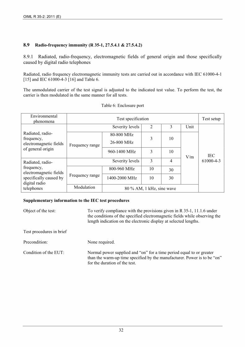
8.9 Radio-frequency immunity (R 35-1, 27.5.4.1 & 27.5.4.2)
8.9.1 Radiated, radio-frequency, electromagnetic fields of general origin and those specifically caused by digital radio telephones Radiated, radio frequency electromagnetic immunity tests are carried out in accordance with IEC 61000-4-1 [15] and IEC 61000-4-3 [16] and Table 6. The unmodulated carrier of the test signal is adjusted to the indicated test value. To perform the test, the carrier is then modulated in the same manner for all tests.
Table 6: Enclosure port
Environmental phenomena Test specification Test setup
Radiated, radio-frequency, electromagnetic fields of general origin
Severity levels 2 3 Unit
IEC 61000-4-3
Frequency range
80-800 MHz
26-800 MHz 3 10
V/m 960-1400 MHz 3 10
Radiated, radio-frequency, electromagnetic fields specifically caused by digital radio telephones
Severity levels 3 4
Frequency range 800-960 MHz 10 30
1400-2000 MHz 10 30
Modulation 80 % AM, 1 kHz, sine wave Supplementary information to the IEC test procedures Object of the test: To verify compliance with the provisions given in R 35-1, 11.1.6 under
the conditions of the specified electromagnetic fields while observing the length indication on the electronic display at selected lengths.
Test procedures in brief Precondition: None required. Condition of the EUT: Normal power supplied and “on” for a time period equal to or greater
than the warm-up time specified by the manufacturer. Power is to be “on” for the duration of the test.
OIML R 35-2: 2011 (E)
33
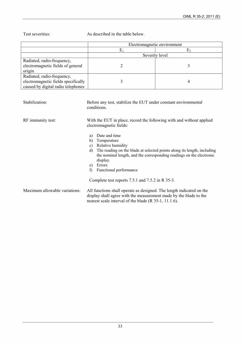
Test severities: As described in the table below. Electromagnetic environment E1 E2 Severity level Radiated, radio-frequency, electromagnetic fields of general origin
2 3
Radiated, radio-frequency, electromagnetic fields specifically caused by digital radio telephones
3 4
Stabilization: Before any test, stabilize the EUT under constant environmental
conditions.
RF immunity test: With the EUT in place, record the following with and without applied
electromagnetic fields:
a) Date and time b) Temperature c) Relative humidity d) The reading on the blade at selected points along its length, including
the nominal length, and the corresponding readings on the electronic display.
e) Errors f) Functional performance Complete test reports 7.5.1 and 7.5.2 in R 35-3.
Maximum allowable variations: All functions shall operate as designed. The length indicated on the
display shall agree with the measurement made by the blade to the nearest scale interval of the blade (R 35-1, 11.1.6).
OIML R 35-2: 2011 (E)
34
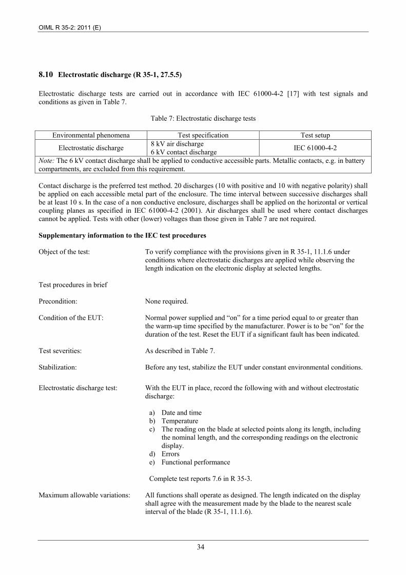
8.10 Electrostatic discharge (R 35-1, 27.5.5) Electrostatic discharge tests are carried out in accordance with IEC 61000-4-2 [17] with test signals and conditions as given in Table 7.
Table 7: Electrostatic discharge tests
Environmental phenomena Test specification Test setup
Electrostatic discharge 8 kV air discharge 6 kV contact discharge IEC 61000-4-2
Note: The 6 kV contact discharge shall be applied to conductive accessible parts. Metallic contacts, e.g. in battery compartments, are excluded from this requirement. Contact discharge is the preferred test method. 20 discharges (10 with positive and 10 with negative polarity) shall be applied on each accessible metal part of the enclosure. The time interval between successive discharges shall be at least 10 s. In the case of a non conductive enclosure, discharges shall be applied on the horizontal or vertical coupling planes as specified in IEC 61000-4-2 (2001). Air discharges shall be used where contact discharges cannot be applied. Tests with other (lower) voltages than those given in Table 7 are not required. Supplementary information to the IEC test procedures Object of the test: To verify compliance with the provisions given in R 35-1, 11.1.6 under
conditions where electrostatic discharges are applied while observing the length indication on the electronic display at selected lengths.
Test procedures in brief Precondition: None required. Condition of the EUT: Normal power supplied and “on” for a time period equal to or greater than
the warm-up time specified by the manufacturer. Power is to be “on” for the duration of the test. Reset the EUT if a significant fault has been indicated.
Test severities: As described in Table 7. Stabilization: Before any test, stabilize the EUT under constant environmental conditions.
Electrostatic discharge test: With the EUT in place, record the following with and without electrostatic
discharge:
a) Date and time b) Temperature c) The reading on the blade at selected points along its length, including
the nominal length, and the corresponding readings on the electronic display.
d) Errors e) Functional performance Complete test reports 7.6 in R 35-3.
Maximum allowable variations: All functions shall operate as designed. The length indicated on the display
shall agree with the measurement made by the blade to the nearest scale interval of the blade (R 35-1, 11.1.6).
OIML R 35-2: 2011 (E)
35
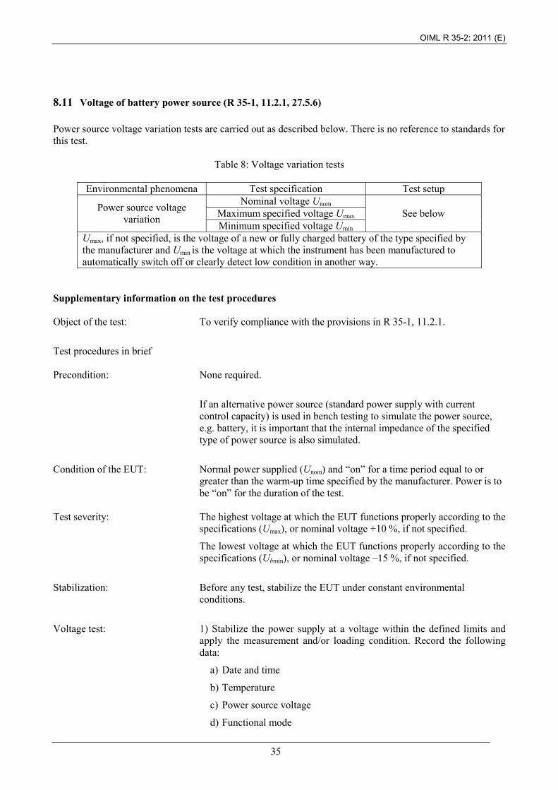
8.11 Voltage of battery power source (R 35-1, 11.2.1, 27.5.6) Power source voltage variation tests are carried out as described below. There is no reference to standards for this test.
Table 8: Voltage variation tests
Environmental phenomena Test specification Test setup
Power source voltage variation
Nominal voltage Unom See below Maximum specified voltage Umax
Minimum specified voltage Umin Umax, if not specified, is the voltage of a new or fully charged battery of the type specified by the manufacturer and Umin is the voltage at which the instrument has been manufactured to automatically switch off or clearly detect low condition in another way.
Supplementary information on the test procedures Object of the test: To verify compliance with the provisions in R 35-1, 11.2.1.
Test procedures in brief Precondition: None required.
If an alternative power source (standard power supply with current control capacity) is used in bench testing to simulate the power source, e.g. battery, it is important that the internal impedance of the specified type of power source is also simulated.
Condition of the EUT: Normal power supplied (Unom) and “on” for a time period equal to or
greater than the warm-up time specified by the manufacturer. Power is to be “on” for the duration of the test.
Test severity: The highest voltage at which the EUT functions properly according to the
specifications (Umax), or nominal voltage +10 %, if not specified.
The lowest voltage at which the EUT functions properly according to the specifications (Ubmin), or nominal voltage –15 %, if not specified.
Stabilization: Before any test, stabilize the EUT under constant environmental
conditions.
Voltage test: 1) Stabilize the power supply at a voltage within the defined limits and
apply the measurement and/or loading condition. Record the following data:
a) Date and time
b) Temperature
c) Power source voltage
d) Functional mode

OIML R 35-2: 2011 (E)
36
e) Measurements and/or loading condition
f) Indications (as applicable)
g) Errors
h) Functional performance
2) Raise the power voltage to the EUT to Umax or Unom +10 %, and note the following data:
a) Power supply voltage
b) Indications
c) Errors
d) Functional performance, including response of the EUT to high supply voltage, e.g. indication or switch off
e) Other relevant responses of the instrument
3) Reduce the power voltage to the EUT to Umin or Unom – 15 %, or until the equipment clearly ceases to function properly according to the specifications and metrological requirements, if higher, and note the following data:
a) Power supply voltage
b) Indications
c) Errors
d) Functional performance, including response of the EUT to low supply voltage, e.g. indication or switch off
e) Other relevant responses of the instrument
Number of test cycles: At least one test cycle for each functional mode
Complete test report 7.7 in R 35-3.
Maximum allowable variations: All functions shall operate as designed at Umax and Umin. The length
indicated on the display shall agree with the measurement made by the blade to the nearest scale interval of the blade (R 35-1, 11.1.6). Outside these levels, an error signal may be displayed or the EUT goes out of service.
OIML R 35-2: 2011 (E)
37
9 Test program for type approval
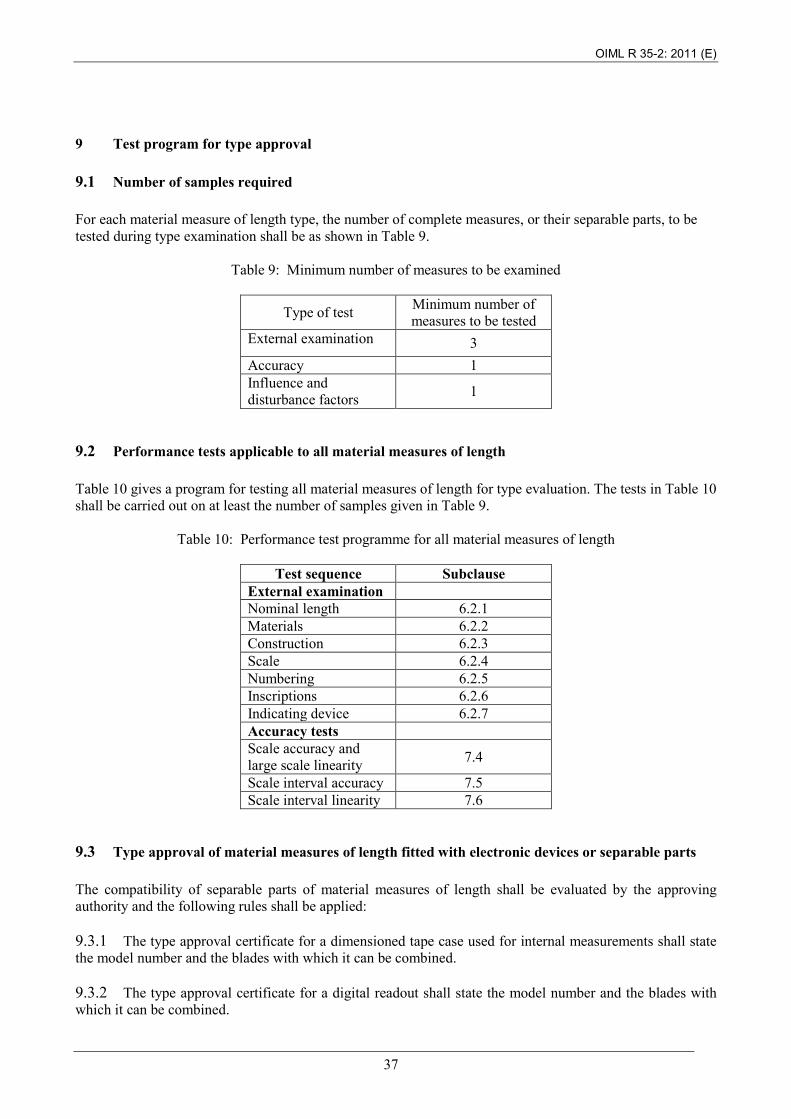
9.1 Number of samples required For each material measure of length type, the number of complete measures, or their separable parts, to be tested during type examination shall be as shown in Table 9.
Table 9: Minimum number of measures to be examined
Type of test Minimum number of measures to be tested
External examination 3 Accuracy 1 Influence and disturbance factors 1
9.2 Performance tests applicable to all material measures of length Table 10 gives a program for testing all material measures of length for type evaluation. The tests in Table 10 shall be carried out on at least the number of samples given in Table 9.
Table 10: Performance test programme for all material measures of length
Test sequence Subclause External examination Nominal length 6.2.1 Materials 6.2.2 Construction 6.2.3 Scale 6.2.4 Numbering 6.2.5 Inscriptions 6.2.6 Indicating device 6.2.7 Accuracy tests Scale accuracy and large scale linearity 7.4
Scale interval accuracy 7.5 Scale interval linearity 7.6
9.3 Type approval of material measures of length fitted with electronic devices or separable parts The compatibility of separable parts of material measures of length shall be evaluated by the approving authority and the following rules shall be applied: 9.3.1 The type approval certificate for a dimensioned tape case used for internal measurements shall state the model number and the blades with which it can be combined. 9.3.2 The type approval certificate for a digital readout shall state the model number and the blades with which it can be combined.

OIML R 35-2: 2011 (E)
38
9.3.3 The type approval certificate for an electronic sensing device shall state the model number and the blades (dip tapes) with which it can be combined. 9.3.4 Table 11 shows the performance test programme for the electronic devices or separable parts.
Table 11: Performance test programme for measures fitted with electronic devices or separable parts
Test sequence Subclause Accuracy tests Accuracy of other metrological components
7.7
Accuracy tests for indicating devices 7.8
Electronic devices - Influence factor and disturbance tests
Static temperatures 8.6 Damp heat, cyclic 8.7 Mechanical shock 8.8 Radio-frequency immunity 8.9
Electrostatic discharge 8.10 Voltage of battery power source 8.11
9.3.5 Where applicable, the test conditions applied during the type evaluation of a complete measure of length shall be applied to the separable parts. Where this is not possible for certain test conditions, simulated conditions, of equivalent severity and duration, shall be applied. 9.3.6 The performance test requirements of sections 7 and 8 shall be met where applicable. 9.3.7 The results of the type evaluation tests of separable parts of a material measure of length shall be declared in a report of similar format to that for a complete measure (see R 35-3).
10 Test program for initial verification
10.1 Tests for initial verification In general, only material measures of length which have been approved either as a complete measure or as a separately approved case or electronic sensing device and subsequently assembled into a complete (combined) measure, shall be eligible for initial verification. However, metrological authorities may allow substitution in service of separately approved electronic sensing devices if it has been proven during type evaluation that such substitutions will not result in the combined maximum permissible errors of the separable parts exceeding the respective maximum permissible errors for a complete measure. Any special requirements for initial verification testing, detailed in the type approval certificate, shall be applied. Where sampling is used, lots shall be tested according to ISO 2859-1 [18] with a single sampling plan and inspection level II unless a tightened inspection regime or double sampling plan is deemed necessary. The AQL shall be determined by national regulations, or in their absence by:
OIML R 35-2: 2011 (E)
39
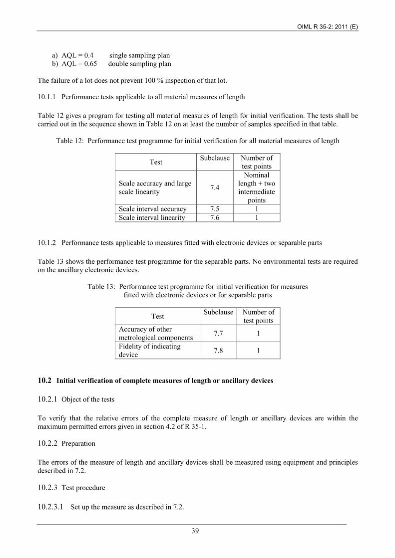
a) AQL = 0.4 single sampling plan b) AQL = 0.65 double sampling plan
The failure of a lot does not prevent 100 % inspection of that lot.
10.1.1 Performance tests applicable to all material measures of length Table 12 gives a program for testing all material measures of length for initial verification. The tests shall be carried out in the sequence shown in Table 12 on at least the number of samples specified in that table.
Table 12: Performance test programme for initial verification for all material measures of length
Test Subclause Number of test points
Scale accuracy and large scale linearity 7.4
Nominal length + two intermediate
points Scale interval accuracy 7.5 1 Scale interval linearity 7.6 1
10.1.2 Performance tests applicable to measures fitted with electronic devices or separable parts Table 13 shows the performance test programme for the separable parts. No environmental tests are required on the ancillary electronic devices.
Table 13: Performance test programme for initial verification for measures fitted with electronic devices or for separable parts
Test Subclause Number of test points
Accuracy of other metrological components 7.7 1
Fidelity of indicating device 7.8 1
10.2 Initial verification of complete measures of length or ancillary devices
10.2.1 Object of the tests To verify that the relative errors of the complete measure of length or ancillary devices are within the maximum permitted errors given in section 4.2 of R 35-1.
10.2.2 Preparation The errors of the measure of length and ancillary devices shall be measured using equipment and principles described in 7.2.
10.2.3 Test procedure 10.2.3.1 Set up the measure as described in 7.2.
OIML R 35-2: 2011 (E)
40
10.2.3.2 Apply the performance tests listed in Tables 11 and 12, where applicable, calculate the errors and compare with the mpe. 10.2.3.3 Complete initial verification R 35-3 II, 1 and 2.
11 Presentation of results
11.1 Object of reports To record and present the work carried out by the testing laboratory, including the results of the tests and examinations and all relevant information accurately, clearly and unambiguously, in the format given in R 35-3 [19]. Note: Implementation of the Test Report Format [19] is informative with regard to implementation of this Recommendation in national regulations; however, its implementation is mandatory in the framework of OIML B 3 OIML Basic Certificate System for OIML Type Evaluation of Measuring Instruments [20].
11.2 Identification and test data to be included in records
11.2.1 Type evaluation The record of a type evaluation shall contain:
a) A precise identification of the test laboratory and the EUT; b) The calibration history of all instrumentation and measuring devices used for the tests; c) Exact details of the conditions during which the various tests were carried out, including any
specific test conditions advised by the manufacturer; d) The results and conclusions of the tests, as required in this Recommendation; e) The limitations applying to the application of separately approved dimensioned cases or electronic
sensing devices.
OIML R 35-2: 2011 (E)
41
11.2.2 Initial verification The record of an initial or periodic verification test for an individual measure of length shall include as a minimum:
a) Identification of testing laboratory:
• name and address.
b) Identification of measure of length tested:
• name and address of the manufacturer or the trademark used; • the accuracy class; • the designation of the measure of length, e.g. flexible steel tape measure with winding
device; • type or model number; • the nominal length; • year of manufacture and the serial number of the measure tested (if any).
c) The results and conclusions of the tests.
OIML R 35-2: 2011 (E)
42
Bibliography
[1] OIML V 2-200:2010
International Vocabulary of Metrology - Basic and general concepts and associated terms (VIM) 3rd Edition (Bilingual E/F). (Edition 2007 with corrections)
[2] OIML V 1:2000 International Vocabulary of Terms in Legal Metrology (VIML)
[3] OIML G 13:1989 Planning of metrology and testing laboratories
[4] OIML D 11:2004 and E 5:2010 General requirements for electronic measuring instruments
[5] IEC Publication 60068-1 – Ed. 6.0 (1988-06)
Environmental testing. Part 1: General and guidance
[6] IEC Publication 60068-1-am1 – Ed. 6.0 (1992-04), Amendment 1
Environmental testing. Part 1: General and guidance.
[7] IEC Publication 60068-3-1 – Ed. 1.0 (1974-01)
Environmental testing - Part 3: Background information - Section One: Cold and dry heat tests
[8] IEC Publication 60068-3-1A – Ed. 1.0 (1978-01)
Environmental testing - Part 3: Background information - First supplement
[9] IEC Publication 60068-2-2 – Ed. 5.0 (2007-07)
Environmental testing - Part 2: Tests. Tests B: Dry heat
[10] IEC Publication 60068-2-1 – Ed. 6.0 (2007-03)
Environmental testing - Part 2: Tests. Tests A: Cold
[11 ] IEC Publication 60068-3-4 – Ed. 1.0 (2001-08)
Environmental testing - Part 3-4: Supporting documentation and guidance - Damp heat tests
[12] IEC Publication 60068-2-30 – Ed. 3.0 (2005-08)
Environmental testing - Part 2-30: Tests - Test Db: Damp heat, cyclic (12 h + 12 h cycle)
[13] IEC 60068-2-31– Ed. 2.0 (2008-05) Environmental testing. Part 2: Tests. Test Ec: Drop and topple, primarily for equipment-type specimens
[14] IEC 60068-2-47 – Ed. 3.0 (2005-04) Environmental testing - Part 2-47: Test - Mounting of specimens for vibration, impact and similar dynamic tests
[15] IEC Publication 61000-4-1 – Ed. 3.0 (2006-10)
Electromagnetic compatibility (EMC) - Part 4-1: Testing and measurement techniques - Overview of IEC 61000-4 series
[16] IEC Publication 61000-4-3– Ed. 3.1 (2008-04)
Electromagnetic compatibility (EMC) - Part 4-3 : Testing and measurement techniques - Radiated, radio-frequency, electromagnetic field immunity test
[17] IEC Publication 61000-4-2Ed. 2 (2008-12)
Electromagnetic compatibility (EMC)- Part 4-2: Testing and measurement techniques - Electrostatic discharge immunity test
[18] ISO 2859-1:1999 with Cor 1:2001 and Amd 1:2011
Sampling procedures for inspection by attributes. Part 1: Sampling schemes indexed by acceptance quality limit (AQL) for lot-by-lot inspection.
[19] OIML R 35-3:2011 Material measures of length for general use. Part 3: Test report format
[20] OIML B 3:2011 OIML Basic Certificate System for OIML Type Evaluation of Measuring Instruments