Embed Size (px)
Citation preview
~:;~'1 )A/"&-
fOL-J/ ~{Z.-- 3>
. \ ABANDONMENTO~ILLED HOLES
CENTRAL NEVADATEST AREA
IT LAS lIEGt\S unRARYPROPERTY OF
U.S.GOVERNMENT
6NIX & SCISSON, INC.5105 EAST 15th STRUT
TULS.... OKLAHOMA 74112
MARCH 1973LFENIX & SCISSON. INC.
300 L"'S VEG S BOULEVARD SOUTHL"'S VEG S. NEV"'DA 89101
L
U. I. ATOMIC INBROY COlllolllIlON CONTUCT U(26-1I·18

DISCLAIMER Portions of this document may be illegible in electronic image products. Images are produced from the best available original document.
,
,
ABANDONMENT
OF DRI LLED HOLES
CENTRAL NEVADA TEST AREA
MARCH 1973

This page intentionally left blank
Pr'6l?ert~0/U.S. DEPARTMEN~ ENERGY
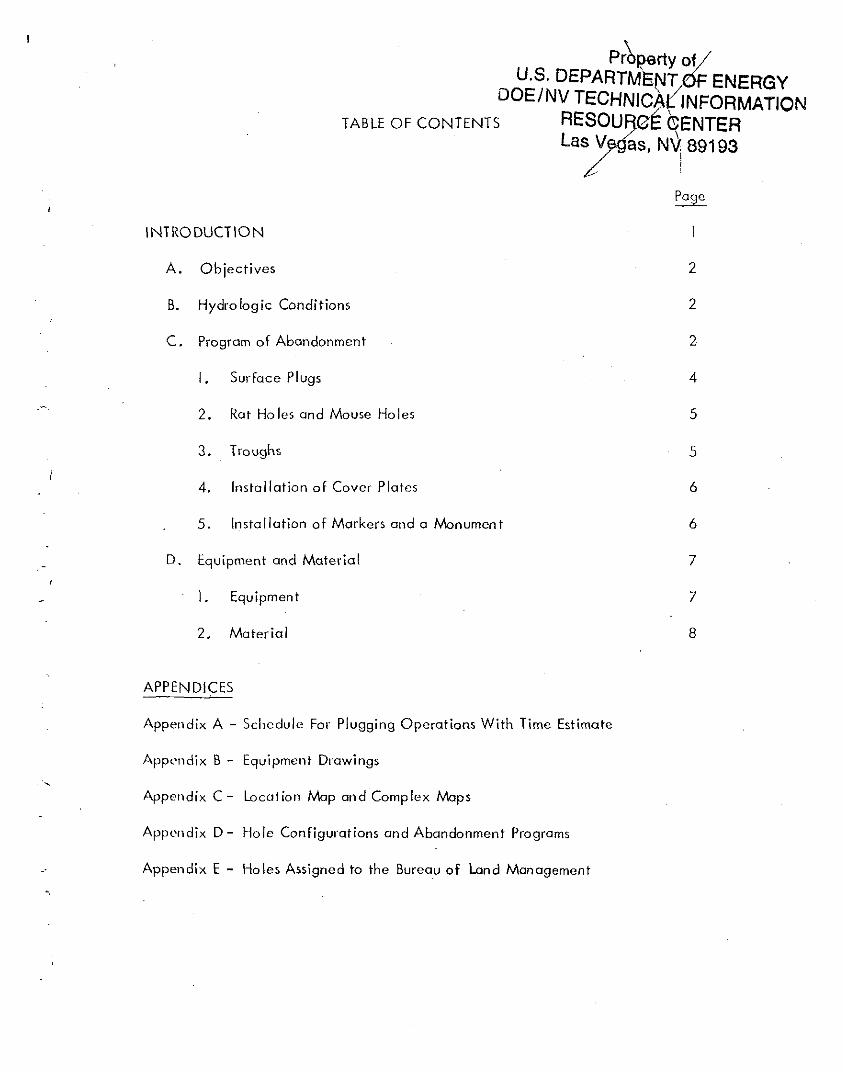
DOE/NV TECHN'C~t:: INFORMATIONTABLE OF CONTENTS RE~OU0E e..ENTER
las Vas, NV 89193:. .
Page
INTRODUCTION
A. Objectives 2
B. Hydrologic Conditions 2
C. Program of Abandonment 2
I . Surface Plugs 4
.~2. Rot Ho les and Mouse Holes 5
3. Troughs 5
4. Installation of Cover Plates 6
5. Installation of Markers ond a Monumen t 6
D. Equipment and Material 7
1. Equipment 7
2. Material 8
APPENDICES
Appendix A - Schedule For Plugging Operotions With Time Estimate
Appundi x B - Equipment Drawings
Appendix C - Location Map and Complex Maps
Appendix D - Hole Configurations and Abandonment Programs
Appendix E - Holes Assigned to the Bureau of Land Management
'.

This page intentionally left blank
INTRODUCTION
The purpose of this document is to establish a detailed plan for disposition of the 37
drilled holes which were used by the AEC in Central Nevado. Five of the holes
will be assigned to the U.S. Bureau of Land Management (BLM). See Appendix E.
Abandoning or plugging the remaining 32 holes will be accomplished in two phases.
The three large-diameter holes (UC-3, UC-3 Cannister and UC-4) will be plugged
for safety and in a manner that will permit ease af reentry. Phcise I will cover
operations on 28 holes in Fiscal Year 1974. Phase II will cover future abandonment
of the 4 water monitoring holes if and when monitoring is no longer required. The
plan is based on the parameter of geology, safety, and ecology. This document
establ ishes the abandonment ob jectives and provides a program for ach iev ing these
objectives. A list of equipment and material required to accomplish the progrom
and an estimate of time required to complete the work is included in the plan.
As a matter of courtesy, the AEC will advise the Nevada State Engineer of the
abandonment program details. Copies of this plan will also be sent to the Bureau
of Land Management.
A. Ob jectives
The objectives of the abandonment program are as follows:
I.
2.
3.
4.
Plug UC-3, UC-3 Cannister and UC-4 in a manner that will allow them
to be easi Iy reentered if required.
Abandon the other holes so that all possible contamination remains below
ground leve I.
Eliminate all potential hazards to man and wildlife.
Abandon the monitoring holes, after they are no longer required, usmq
a minimum of equipment and material.
B. Hydrologic Conditions
Fresh water is,present in all of the AEC drilled holes in Central Nevada.
Holes in Little Fish Lake, Hot Creek, Little Smokey, Antelope, Monitor and
Ralston Valleys are to be plugged or abandoned at this time. The static
wot er level ranges from abave ground level to 565 feet below ground level.
WotPI movement through the formation tends to be lateral or downward at
mosl of the locations to be abandoned.
C. PIO(Jiom of Abandonment
The main premise upon which the abandonment program is based is the re
quirement to completely seal all holes below ground level and to eliminate
all safety hazards.
-2-
In preparing the abandonment program, it was assumed that the abandonment
procedures would be accomplished by using as much equipment and materials
from the Central Nevada Test Site as possible. Because of the lack of
necessary services in this remote area, avai lable services from NTS, Reno,
Ely or Tonopah will be utilized. Cement plugs can be placed in UCE-IO and
UCE-18 by Ha IIiburton under their present contract. Cement pi ugs required
for all other holes can be furnished by lacal ready mix concrete suppliers at
less cost than is possible by Halliburton. Smail amounts (3 to 5 cu. ft.) of
cement can be mixed and placed by hand in the very small-diameter holes.
Fabrication and methods of placing and securing the surface plugs and com
pletely sealing all holes, except UC-3, UC-3 Cannister, UC-4, UCE-IO
and UCE-18, will be accomplished in a manner similar to the operations
conducted on Amchitka Island.
This work shall be accomplished using the minimum amount of labor and
supervised by a qualified drilling engineer. Specifically, the labor needed
includes truck operators, a front end loader operator, welders, crane oper
ators and laborers. From experience gained during the abandonment operations
ot Amchitka, having qualified laborers and an expert welder available will
accelerate the abandonment operation. It is anticipated that while operations
such as excavating or cutting casing are proceeding on one hole; other plug
ging operations wi II continue simultaneously. It is further anticipated that,
when possible, the holes will be prepared for plugging ahead of time so that
the cement contractor can plug several holes during each trip to the work site.
-3-
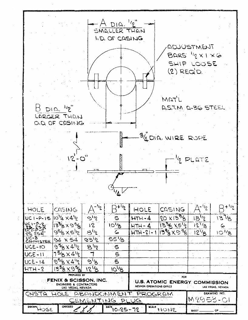
I.· Surface Plugs
Ten-foot cement plugs in the top of the casing appear to be adequate for
all of the holes that are being abandoned at this time except UCE-IO and
UCE-18. See Appendix D.
A total volume of approximately 3550 cubic feet of slurry will be required
for surface plugs. The volume required for each hole varies from one
cubic foot in the 2-3/8 inch tubing strings to 392 cubic feet required for
each of the three large-diameter ho res.
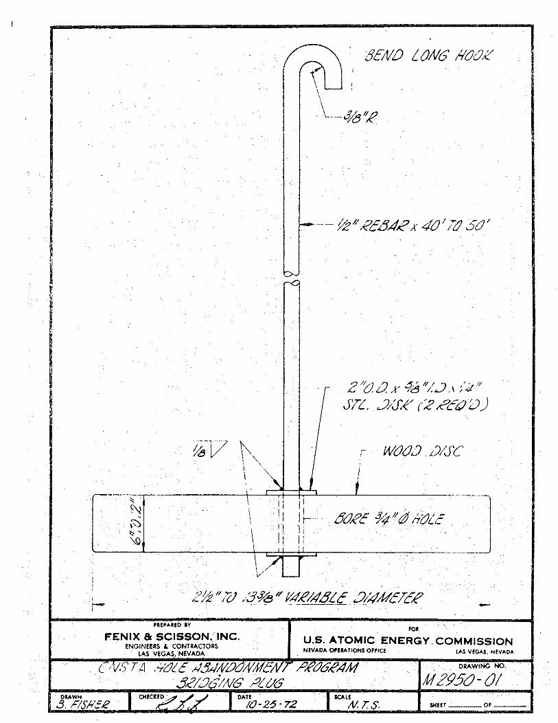
To retain the cement plugs in the upper 10 feet of the casing, wooden
plugs, like those used on Amchitka Island, will be placed in the open
casing. See Drawing No. M2950-01. Prior to running the plug, the
fluid level must be lowered to 10 feet. The wooden plugs will be secured
to the casing by attaching 1/2 or 3/4 inch rebar to the casing, so that
the wooden plug and cement plug cannot possibly move down the hole.
'The numerous un cemented annular spaces wi II be bridged and cemented
u,ing a supported split plate as shown on Drawing No. M2953-01 ..
The successful use of wooden plugs on Amchitka Island is a good recom
mendation for their use at Central Nevada. Wooden plugs are less
expensive to fabricate and install than other plug types. Installation
of a Baker type plug using a Birdwell truck and mast would cost $1,680.00
(including mileage) for the first 4-1/2 inch plug and from $555.00 to
-4-
$1,059.00 (depending on size) per hole thereafter. In addition, Birdwell
will charge $300.00 set up charge for each hole. The costs therefore
dictote thot wooden plugs be procured and used.
2. Rot Holes ond Mouse HoIes,
For definitive purposes, these holes are shallow (30' to 40' deep) vertical
drilled holes adjacent to the rig floor. Rot holes are used as a place to
set the kelly out of the way when it is not being used, and mouse holes
are used for making drill pipe connections. The holes ore not used once
the drilling rig is moved owoy. Information concerning the number and
the type of these holes presently open ot Central Nevado is not avai 1-
able. If they do exist they will be obondoned by cutting the casing off
ot ground level ond then filling the open hole to the surfoce with cement
or notive moteriol. If cement is to be used it moy be placed either with
Holliburton equipment or by hand. All rot holes and mouse holes csso>
ciated wi th the UC-I Complex, that can be located, will be sampled
by Rod-Safe before they are plugged.
3. Troughs
A number of locations have 3 foot x 15 foot troughs built into the pad.
These troughs will be filled with dirt within I foot of the surface and
copped with cement.
-5-
4. Installation of Cover Plates
To protect the holes against leakage, steel plates, having a suitable
minimum thickness, should be welded over the casing stubs. Inall po,
sible instances, the plate should be welded to the surface casing,
thereby protecting the area inside the casing and also the annuli be
tween casing strings. All annular voids at the surface should be plugged
with cement before the steel plate is installed.
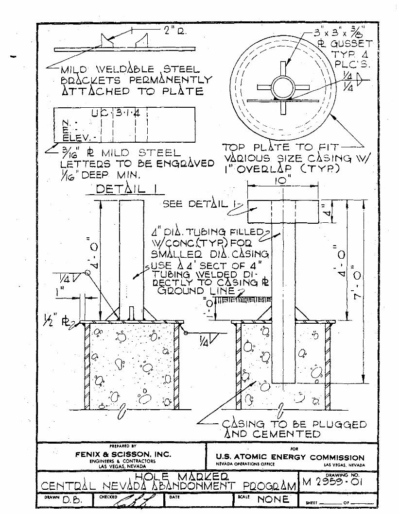
5. Installation of Markers and a Monument
The exact location and identification of all drilled holes (except those
assigned to BLM) at Central Nevada will be identified by prefabricated
stee I markers.
A number of the holes have been previously plugged with cement to
the surface. A cover plate should be welded to the surface casing with
4 feet of 4 inch pipe welded and gussetted to the plate in a vertical
position. A name plate should then be properly secured to the pipe ..
When cementing surface plugs in the other holes, a vertical marker (4
inch pipe) should be installed with a visible identification plate. The
pipe should be of sufficient length to be set 3 feet into the cement and
protrude 4 feet above ground level.
It is anticipated that these identification plates will be prefabricated
and will identify the hole by number and Nevada State coordinates.
-6-
Bead welding of the data on the plate at the site would be more expensive
than in-plant engraving or die stamping. It is recommended that pre
fabricated identification plates be used as hole markers. See F&S
Drawing No. M2959-01.
A permanent stone or concrete monument with appropriate markers will
be erected over Emplacement Hole SGZ of Faultless.
D. Equipment and Material
The abandonment program will require the following equipment and material:
I. Eguipmen t
a. Jack hammer and compressor - Government-owned 600 Ingersoll Rand
compressor and air hammers are currently on site and wi II be required
for removing the cement around the wellheads to allow installation of
the cover p late one foot be low the surface.
b. Front end loader - one cubic yard capacity, required for filling cel
lars, troughs and rat ho les with native soi I prior to capping them
with cement.
c. Truck with winch or "A" frame - required for lowering large wooden
plugs into holes and boiling holes to plug depth. This equipment
will also be used to remove wellhead equipment.
-7-
d. Four pickups - required for hauling tools, cement mixing pans, sack
cement, and personne I.
e. Electric welding machine with a supply of welding rod - required for
welding on plates and markers and welding plug support to casing
stubs.
f. Acetylene cutting torch with a supply of acetylene and oxygen -
required for cutting casing, etc.
g. Crane - required for heavy lifting at UC-4, UC-3 and UC-3 Cannister
if the hole is surface plugged. Will be used in the event the casing
in UC-3 Cannister is floated out of the hole.
2. Material
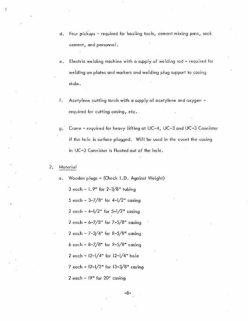
a. Wooden plugs - (Check J.D. Against Weight)
3 each - 1.9" for 2-3/8" tubing
5 each - 3-7/8" for 4-1/2" casing
2 each - 4-1/2" for 5-1/2" casing
2 each ~ 6-7/8" for 7-5/8" casing
2 each - 7-3/4" for 8-5/8" casing
6 each - 8-7/8" for 9-5/8" casing
2 each - 12-1/4" for 12-1/4" hole
7 each - 12-1/2" for 13-3/8" casing
2 each - 19" for 20" casing
-8-
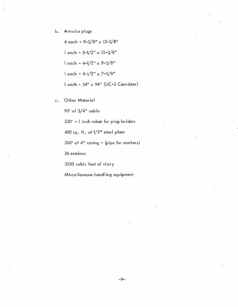
b. Annulus plugs
4 each - 9-5/8" x 13-3/8"
I each - 5-1/2" x 13-3/8"
I each - 4-1/2" x 9-5/8"
I each - 4-1/2" x 7-5/8"
I each - 54" x 94" (UC-3 Cannister)
c. 0 ther Materia I
90' of 3/4" cable
330' - I inch rebar for plug holders
400 sq. ft. of 1/2" steel plate
260' of 4" casing - (pipe for markers)
26 markers
3550 cubic feet of slurry
Miscellaneous handling equipment
-9-

This page intentionally left blank
APPENDIX A
SCHEDULE FOR PLUGGING OPERATIONS
WITH TIME ESTIMATE

This page intentionally left blank
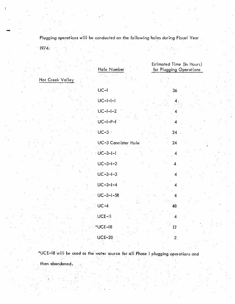
-Plygging operations will be conducted on the following holes during Fiscal Year
1974: .
Hot Creek Valley
Hole Number
UC-I
UC-I-I-I
UC-I-I-2
UC-I-P-I
UC-3 .
UC-3 Cannister Hole
. UC-3-1-1
UC-3-1-2
UC-3-1-3
UC-3-1-4
UC-3-1-5R
UC-'4
UCE-II
. -'UCE-18
UCE-20
Estimated Time (In Hours)for Plugging Operotions
36
4.
4
4
24
24
4
4
4
4
4
48
4
12
2
*UCE-18 will be used as the water source for all Phase I plugging operations and
then abandoned.
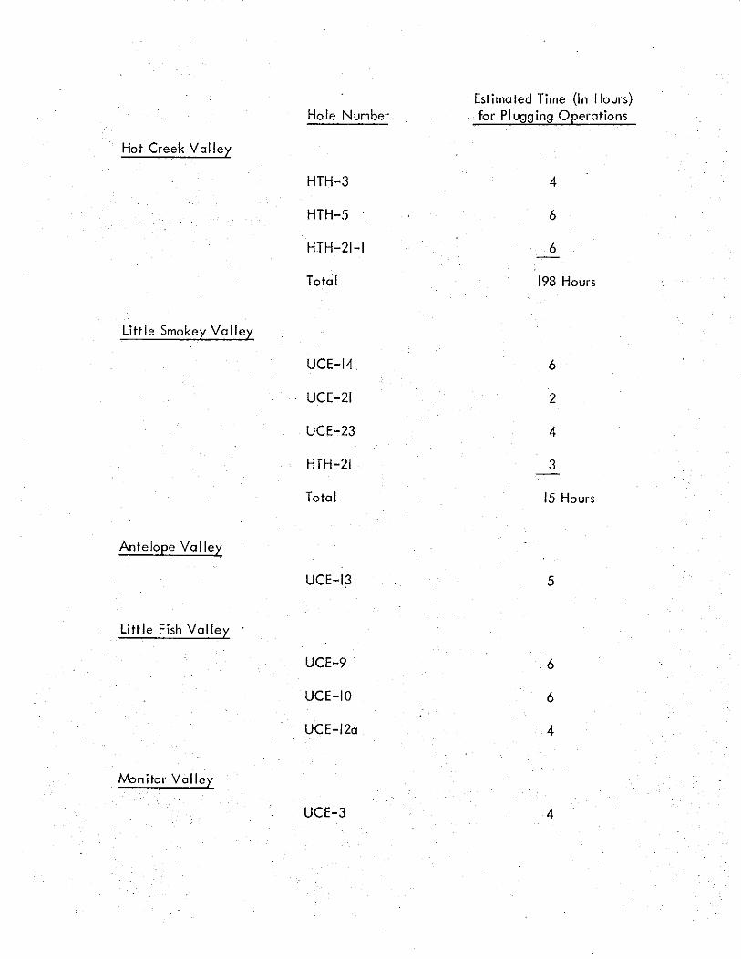
Hot Creek Volley
Hole Number
HTH-3
HTH-5
HTH-21-1
Total
Estimated Time (In Hours)for Plugging Operations
4
6
6
198 Hours
Little Fish Volley
UCE-9 6
UCE-IO 6
UCE-12a 4
Iv'onitor Volley
UCE-3 4
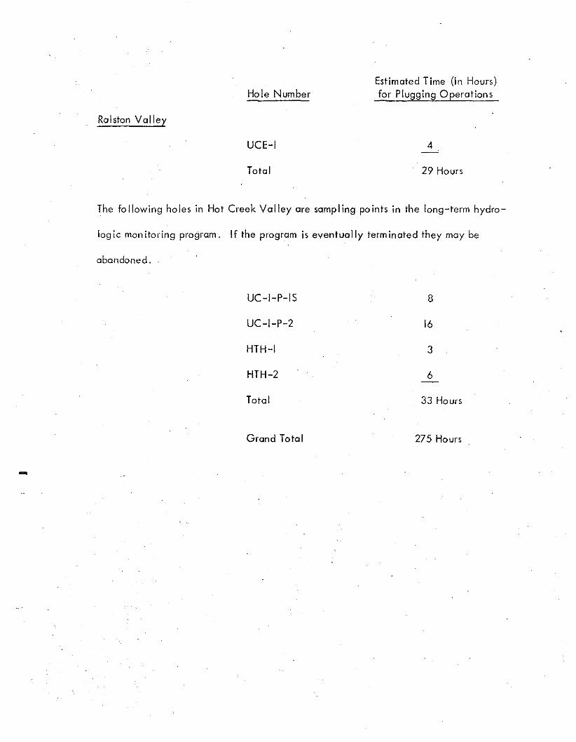
Ralston Valley
Hole Number
UCE-I
Total
Estimated Time (In Hours)for Plugging Operations
4
29 Hours
The following holes in Hot Creek Valley are sampling points in the long-term hydro-
log ie mon itoring program. If the program is eventually term inated they may be
abandoned.
-
UC-I-P-IS
UC-I-P-2
HTH-I
HTH-2
Total
Grand Total
8
16
3
6
33 Hours
275 Hours

This page intentionally left blank
APPENDIX B
EQUIPMENT DRAWINGS

This page intentionally left blank
II
8E;VO LONG #00,<
.
'I 2 12/. u x YcSll/,J.\ ;'4 '1
STi. ,;XJ:< (:2Rc'4J:;J)
-'. ·~INl>'~
,
II,
WOOL? vise
,r- -
FENIX Be SCISSON. INC.ENGINEERS & CONTRACTORS
lAS VEGAS. NEVADA
'0'
U.S. ATOMIC ENERGY,COMMISSIONNlVAOA Of'(lATiONS OFfiCE, lAS VEGAS, NEV....OA
C ,V.5' h1 ,.:,.t:Jtc .4341V'LJ(W,1IEAI. ?RtJ6R4/Y/321udWG ".:J{(/(5
DRAWING NO:
AlZ95{}-OI0"'_ I CHICKID'.4 _/ . ~, I DATE
3. FIS,4'!R ~ lLT 10-26-72 I SCAlf .
Mr.$. $HEfT OF
f-- A D\~. IIi' --'i SM~l.LE.R \"\-\(:;\1'-.\
I, O. cs C.r~'S1 wG
""r~;\\L(),,:S,'1,M C-3r.o. STEYL
\
PRE'ARED IV
FENIX 81 SCISSON. INC.t;NGlNEERS & CONTRACTORS
LAS VEGAS. NEVADA
FO'
u.s. ATOMIC ENERGY COMMISSIONNWADA OPUATlONS O"'ICE lAS VEG,I,$, NEVADA
eN'S.,.\.;, \-40\..£. p,e,C.2.'.\)O()I-..H./\ 'i:..\,~ T PROC.,R o.ME l::..-ML.I,i-T"II·...\·c... Pl.U c.:;,.
DRAWING NO.
M rLC5 S:::, - 0 I.
Ii ' 1I I
.-,/ ~--
/,/;/II
I /{ (
~ \\\=~~~=\ \
\ "" "-',- ........ '-.~
TOP PL TE TO FITV~t210US ?'ZE C1SINO wiI" OVED.LAP (TYP)
II
10
---+--- 1. II Q..
UC'15'/'N. • I I IE· I IEL.EV.. I
MIL,.D \VELD1~LE STEELbQ6C~ETSPEQ.M~NENTLY.6.TT~CHED TO PL~TE
1'Ii' ~ MILO STEELLETTEQ5 TO ~E. ENGfO,t.:.VEDYi<t," DEEP MIN.
.DET~IL I
-
=
-.;;f 0
o, --
=oII \
d OIA. TUe,INC! FILLED?I.---W/c;.ONC.(TYR) FOQ. c9M~LLEQ. DIX. C!.l.5ING IUSE 6.4 I SECT OF 4 II
V4 TUe,INC! WELDED DI-.l.. II" DeCTLY TO C~SINCI ~ I·
Gt20UND L1NE:7
~='_0_, 1111=""'" / I. I'..
~" Jt?~~~~~~ l '\.
FENIX & SCISSON, INC.ENGINEEIlS & CONTRACTORS
LAS VEGAS. NEVADA
fOR
U.S. ATOMIC ENERGY COMMISSIONNEVADA OPERATIONS OfflC! LA! VEGAS. N£V"AOA.
DtAWN O.b. 0<1<1(10 DAn SCALI NO N E·
DRAWING NO.
M '2'3:;~. 01
5t{HT Of

'." -:7k;';:-:'-. . ::OI.JlRt....E"'':'..., $\-tDrIC,.l,T;);::", ~TS I:OR MAT(q;l....S~~ I;: ;,.,~~~n "';.RT$ 2 (. :,;. et" "Cl sr~ 316...7;.
2.~ SKAU.. IE !lIADE FROIiIl EJTK£R TYPE II. Oft ILl AlR--ENllWHlHG• POFIll..AMO a:w;lr't
3. COHCRElt TO HA'VI 4000"" COMf'RfSSlYE STREHGlH IN 28 Dl\YS.
"'- HlGtt-EARLY-~ CEMENT. CALCIUM CHLORIDE AI«) ACCEl..£RAnHG TYPEAtWlXT\,.'Il£S StW..L JKlT lIE USE!l .
5. lIIIAx,liNY AA'iiGR!:GATE SIZE 3HAU. NOT EXt£EO :s":.4. A RETARDING~ SHAll. BE USED W!£MEVER HEC£SSARr 10 PRE
VENT COt.O -.lOlHTS DlJf. to CllUAKTITY Of a»t~ f'\.ACED.
I FrEI~11IIG srea, SKAU. HollIE A 1IIlHl.... YIELD S'TRENG1ll Of 00,000,.MfD :lHAU. CONFtIlIf TO A$lII 9'£CIACAllOH 11-615GfUo.oe: ec,
a.R£jN~ Sl'\.JC£S:LAP TOP BARS 'f1J'LAP 8OTl'OlIrl BARS IZ"
L£J«mt ~811 l8S
SOlE
••NO.
eo•
11)TAL
CONCR£TE"I4.5 CU. 'l'DS.STEEL PLAn: Z' .. 126'" OIA. 7060 L.BS
~--- -,,~~- ,.-0- ==:1
T 1'i -r-,------; --I --r- -t-r-r- --r ...,...~_., I
i ! : f J i I I I J
L ' , I '. I : I : I, . --+---"---.--+--r--+---t--+--'
I Ii I i L- i " i !. ! i.V........I • • I .' , • '. j . Trrr. ----....-~ , .' \ I .I I . I • j - I
_ _ I I ; I I- ! . i :j i! 'J li I I I 'j ,f jj 'r--T-·-'r--r-T-·-i·t-~~+-T------:
ito. Iii i ; I I Ii'; il ' t--+--t. I I -t-i--+-+~~J~,,-o-T-r-l- r t~·-·r1-. J,l·--tH
: . iii J I I I
I 'r-l---l- I -ll- I J,, '1 I I --+---1N". I : i j I i I ; !I L--+- I. I I ;1 ~ i i
I I' I ! i.,,! II i ' . I I iI , I "', ...~~- j.f ,_.) I :
ill: ,r--' i ~ ;<r-~'l::..;','. 1 1 iI L! ! T T '. ,.otC
• Ti ,,- :' ',Ii_..- '-.. i r3"aD.R'
"- :-'$"ct..EAR
u. ..A~ DlIIERGY OCtQllllSSiON--- ----
I'aa:II~ INC. 1 M~2968-01 0----- -
1<:<T-. UC-3• _ CONCRETE PAD COVER-__'5'7 CENTRAL NEVADA
~ • ABANllONMENT PROGRAM
_-:.A.~\
iI
A~.,.
I
!
--------- --,r-ir --_.__-:
-NOi£S-·
L CQlot$TRUCTlON REQl..lR£U£.NTS, SPECIFICATIONS AND TESTS FOft MATERIALS~ BE ..~ WITH fMTS 2 a 3 (E ACI STANOARO 318-7\.
2..~ SHAlL BE MACE F'RCIil EITHEl't TYP£ I" OR nA AlHJrnWHtH'GPORll...tNOCEJiIEl(1:
3. COHCRETE TO HAV£. 4OOOpUCOMPR£SSlI/£' STRENGTH IN 28 00\'l'S.
4. HlGH-EAR1.'l'-STRDIGTlt CDENT. CALCIUM CHI..ORlO£ N'J ACCEL£RATlNG lYPE~ StWJ. ect.ee u:sm.
s, WAXIWUII AGGREGATE SIZE' sHALL NOT EXCEED ,".
6. A RETAROOIG AtJNO(,TlI'lE SHAll BE' USED Wt£MEvER NECESSARY 10 PREVENT COl..,D .,l()lt(1"S DtE: 10 QUAIfTTTY OF CONCR£TE PlACED.
1. REINFORCING STEEl.. ~u. HAllE A MINIMOW YIELD STREHGl'H~ 6OJ)OOplIlAND SHALL COHR:IRM TO AS'" SfECIFlCATIOf't A-6I~ GRADE 6Q.
8. REINfOftCElllEMT SPLICES;LAP TOP BARS Itt'LAP llOTTOM BARS tz'"
u. .. ATOMIC~y COMMlSSION---_. ....._-UC-3 CANNISTER HOLE
oM-2969-01
CONCRETE PAO COVERCENTRAL NEVADA
ABANDONMENT PROGRAM. -!'D1UI_.c_ INC. I---
i.,.
-IJ\o'i~II'lr.·EXCAVA"r1QN
,_~.ECTION .~ ..
ANNtJl...US TO BE CAP1'EO WlTllrJ' C(MENT PLuG

This page intentionally left blank
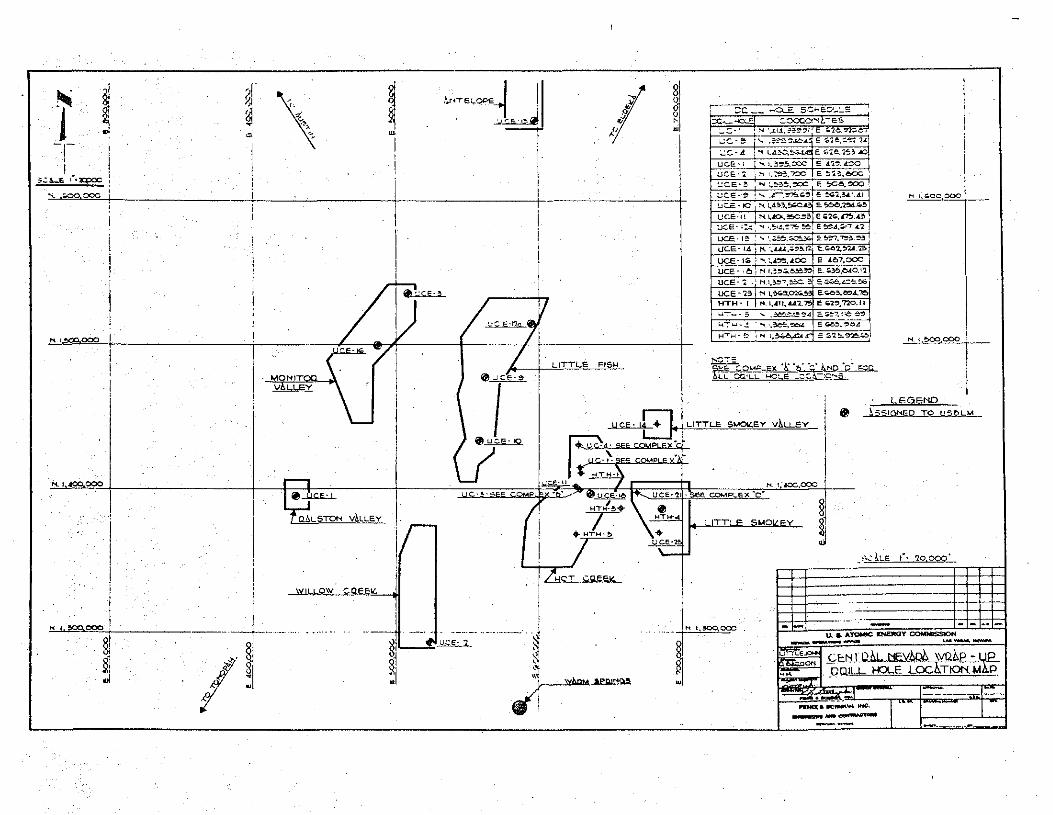
APPENDIX C
LOCATION MAP AND COMPLEX MAPS

This page intentionally left blank
i~ !..-.
-~t,
,
§~
i§
0~
--
-
§
ei~1
-z
w~~-,-t.
-~•
·Ojml
o::lO~
31 61§.
:]l>
d{
w~
:J
~.~~
.1
z:~>
lur
~Ij
~'f
•~'s
~
ut·III
.J
~\::lill
elli
t-'
tt
z
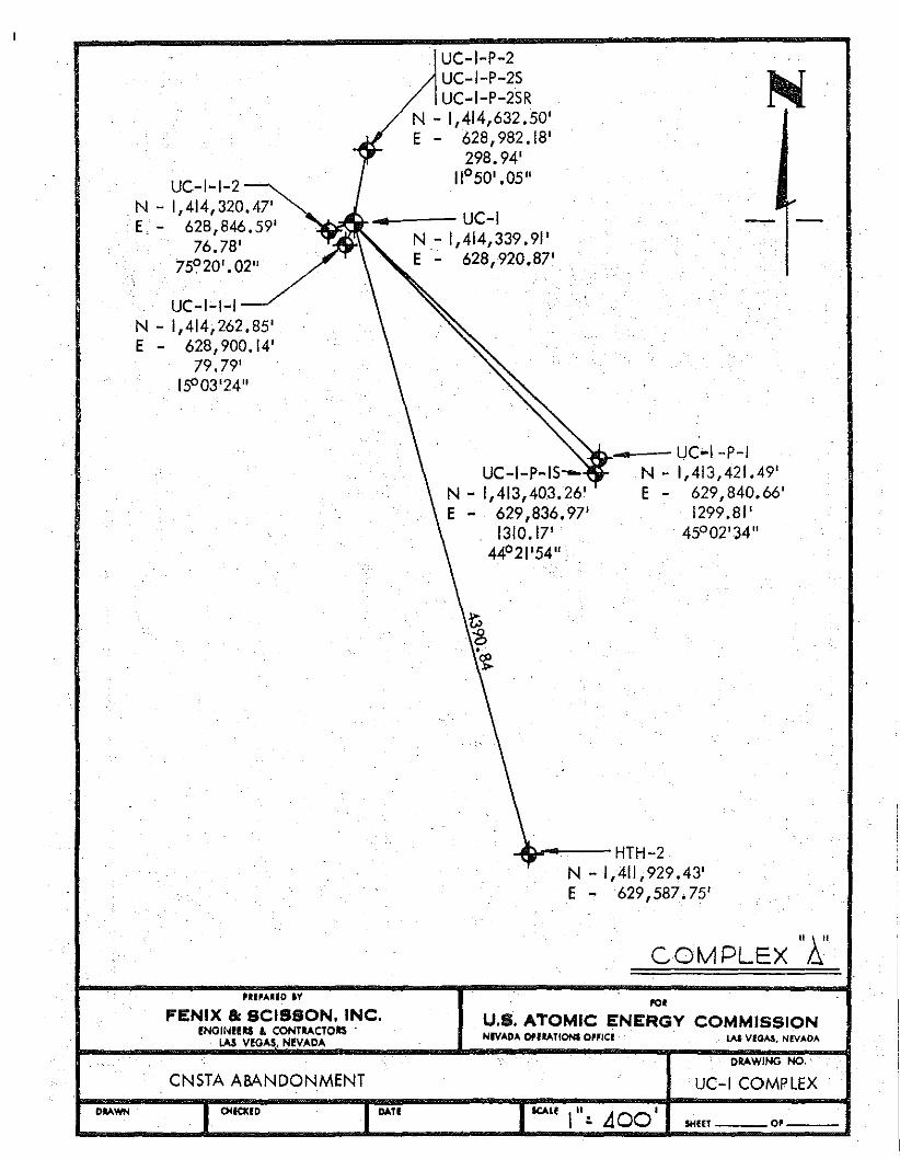
...~ - UC·I -P-IUC-I-P-IS-- N - 1,413,421.49'
N - 1,413,403.26' E - 629,840.66'E - 629,836.97' 1299.81'
1310.17' 45°02'34"44°21'54" ,
-4tl..--- HTH-2N - 1,411,929.43'E - 629,587.75'
UC-I-P-2UC-I-P-2SUC-I-P-2SR
N - 1,414,632.50'E - 628,982.18'
298.94'11°50' .05"
__--UC-I~~ N - 1,414,339.91'
E - 628,920.87'
UC-I-I-IN - 1,414;262.85'E - 628,900.14'
79.79'IS003'24"
UC-I-I-2N - 1,414,320.47'E. - 628,846.59'
76.78'75°20' .02"
COMPLEX "I;.', •• , ....UO IV
FENIX & SCISSON. INC.ENOINI!IlS £ CONT....CTOIlS '
LA! VEGAS, NEVADA
1'0'
U.S. ATOMIC ENERGY COMMISSIONNIVADA OPIIATIONI Oll"C! LAS VfOAS. NEV....OA
CNsrA ABANDONMENTDRAWING NO.
UC-I COMPLEX
DlAWN ~ICkID DATISCAlf I": 400 I SHUT
...
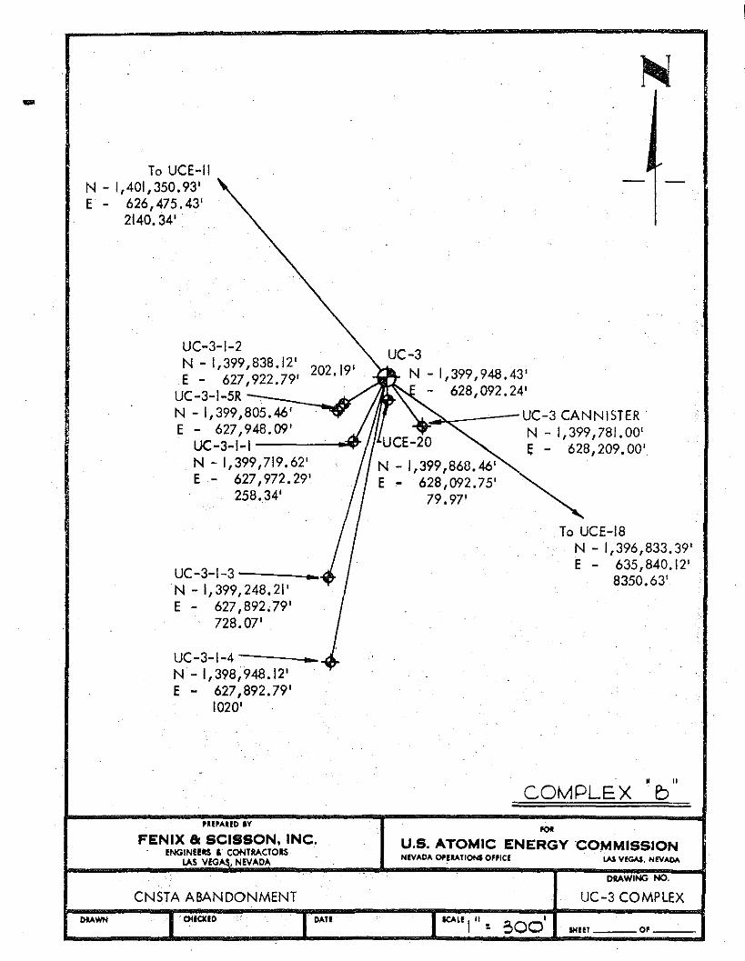
To UCE-IIN - 1,401,350.93'E - 626,475.43'
2140.34'
UC-3-1-2N - 1,399,838.12' 202.19'E - 627,922.79'
UC-3-1-5R ::::--:-:-:_........~N - 1,399,805.46'E - 627,948.09'
UC-3-1-1----'-.....,.N - 1,399,719.62'E - 627,972.29'
258.34'
UC-3-1-3 _N - 1,399,248.21'E - 627,892.79'
728.07'
UC-3-1-4 _N - 1,398,948.12'E - 627,892.79'
1020'
UC-3N - 1,399,948.43'
- 628,092.24'
~~~-'--UC-3CANNISTER'N - 1,399,781.00'
UCE-20 E - 628,209.00'N - 1,399,868.46'E - 628,092.75'
79.97'
To UCE-18N - 1,396,833.39'E - 635,840.12'
8350.63'
. "COMPLEX b
,U'AUD IV
FENIX 8l SCISSON. INC.fNGIN!!ltS , CONTRACTORS
LAS \/EG1. ,NE\l1.D1.
,.,.U.S. ATOMIC ENERGY COMMISSIONNEVADA OfI'l!lATlONI O"ICf LAS VfGA$. NEVADA
DRAWING ~.
UC-3 COMPLEX-- CNSTA ABANDONMENTotlOCID ....n
IC'\L! I". ~OO' SHUT 0'
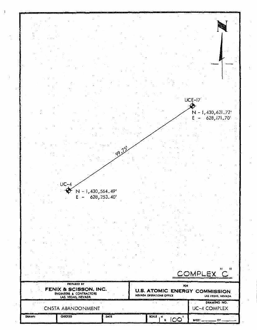
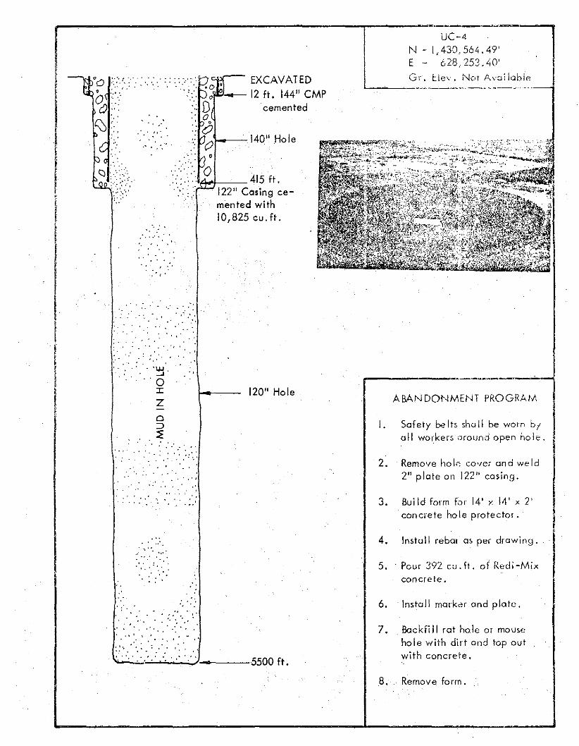
UC-4N - 1,430,564.49'E - 628,253.40'
'UI""IIO IV
FENIX 8l SCISSON. INC.ENGINURS , CONTRACTORS
lAS VEG"S, NEV"0"
CNSTA ABANDONMENT
.
UCE-17
N - 1,430,621.72'E - 628,171.70'
" II
COMPLEX C10'
U.S. ATOMIC ENERGY COMMISSIONNevADA OftI....T/ONS Oll'IC! lAS VfGAS, NI!VAOA
DRAWING NO.
UC-4 COMPLEX
. DMWN I QUCKID I DAte&HEfT 0'
.
UCE-21 -N •. 1,397,350.13'E.;. 668,405.56'
HTH-21
rN - 1,397,350.13'E - 668,505.56'
100'
-
HTH-23 ..N - 1,368,087.00'E - 684,237.00' ""
COMPLEX D'l"AIUD IY
FENIX 8l SCISSON, INC.ENGINE!IlS.f. CONTRACTORS
LAS VEGAS, NevAOA
CNSTA AMNDONMENT
"lO
U.S. ATOMIC ENERGY COMMISSIONNEVADA OPUATIONIO'flCE LAS VEGAs, NEVADA
ORAW.ING NO.
UCE-21 COMPLEX
.OAWN OtICKID ...."$HEft 0'
-
APPENDIX D
HOLE CONFIGURATIONS AND
ABANDONMENT PROGRAMS

This page intentionally left blank
1-0--10-3/4" Casing
low qrour.o Is: Ie I ..
Chip away 48 11 /26 11CYt· .<;:
cement to \ r he l ....,w r,;or..; 1- .'1
C ff r'6" ' ",'ut 0 L C.O'jtng 1 •.;(;1'",11
Rod-':.,fJfE-: rW,I.(,it(t! ;nrJ i'~ -t.·
. qu irr.d tLf r J :J ( j f .r)' ) 1 r)lu(~'r;;,'
op or ction. or. 01\ -,ok:, ;.
UC-I Cornp /r,/.
Cut awol 22" (:/)':.ing or".: :r...away onrvu lor cernf.::rd rJ(.! If'.';!'
B8" and 43 11 casing to I' . ~.
law ground k Ie I,Cut awol 4G lI cos irv; to
ABAr,WOUMEt'l1 PROGP;.u
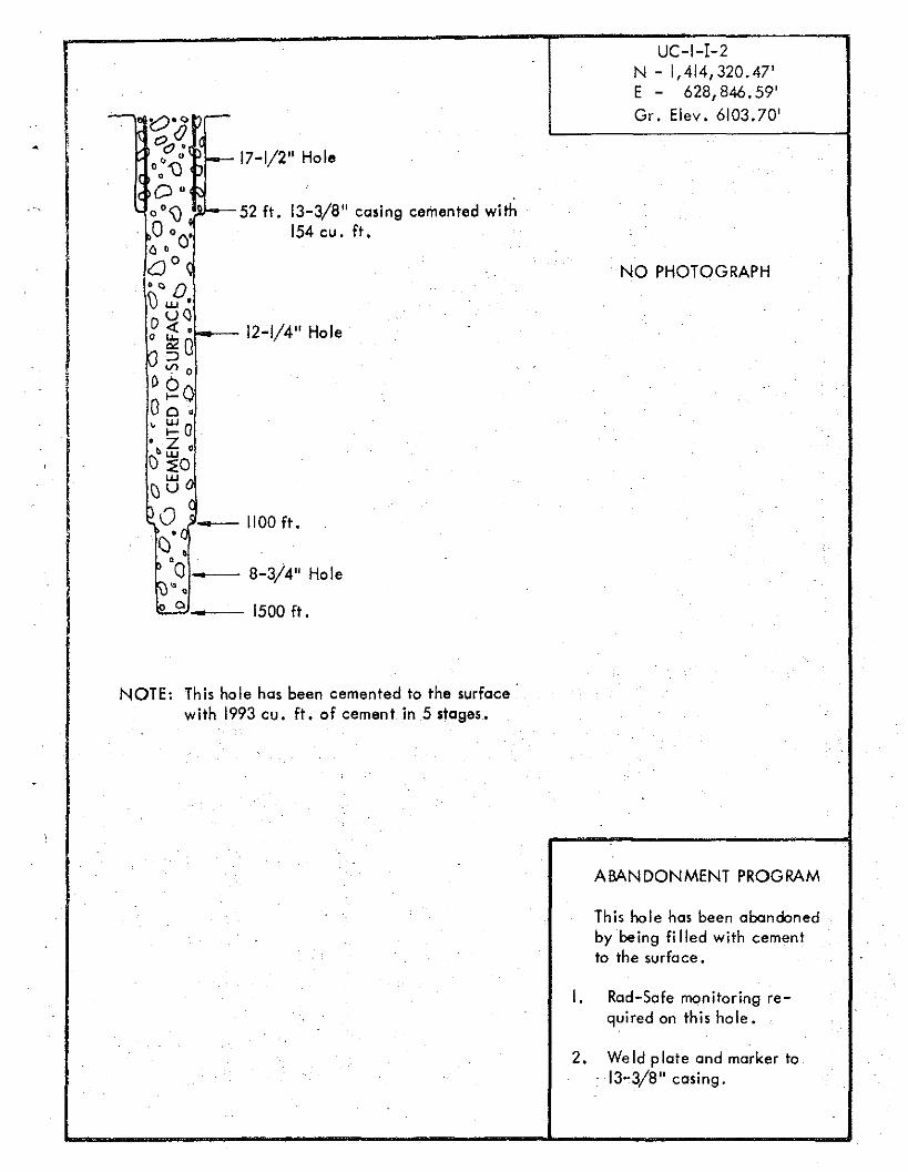
UC-IN - 1,414,339.91'E - 628,920.87'Gr. Elev. 6104.00'
I.
rJ.
3,
4.
2.
EXCAVATED HOLE10 ft. 88" casing cemented with 400 cu. ft.
395 ft. 48" casing~ cemen ted wi th
5696 cu. ft.
'- 400 ft.
--72" Hale
- --- 42" Ho Ie
3250 ft. 26" casing---- cemented with
24,001 cu. ft.'--
------------ 3275 ft.
-',
()
0
lc
I:l
'00
•
0o '\)o
Nl'H: Th is ho lc- has been expended.pad level.
6 .. Remo vr- sternm ino -no tcr io:
from 2611 casing and CJt n ~{
10-3/4" «mp locernenr co:.;!,!!
I' below pad le'lel.1. Weld p lo!r- and mork r-r h ',';,"
. ccsin q , plo co rebar 1 andbacHil1 to pad le/el w,t!45 cu. ft. of c oncr e t e .
B. Find rno use hole or.d Fat, r.. lr_
'if po ssib lc and toh, sorr.plfrom the bo tro m of cad
9. Plug mo us« hole 0;·.101 Lnkwith dill and top off w:ll,l~ell)l'nI.
-
e
EXCAVATED HOLE8 ft. 36" casing cemented with
59 cu. ft.
~-. 26" Hole
.- 97 ft. 20" cosi ng cemen tedwith 380 cu. ft.
- 17-1/2" Hole
.. _- 1300 ft. 13-3/8" c.csinq
cemented with 2316 cu. ft.
UC-I-1-1N -1,414,262.85'E - 628,900.14'Gr. Elev. 6102.40'
o
.ABANDor'4MEtJT PRIJG!-!·-/'
-, .Rao-SafE.; ((\(;(1; jrJJ i~l~i
qu ii e d or. thi-:;' hrJI,:
Romove frarr,(:;'ilorr
from l.ole ,
,r ,
. 2.- 3500 ft.
- - 12-1/4" Hole
c
fe".I DiJ
Til is 1101" is cemented to the surfaceusing 4426 cu. ft. in 4 stages.
3. Excavate ar::>!Jr,C: VIe I !,-r~Q'_.
I' below surface to 36 " ..0 'c,
4. Cut off casing an" re mo,«.
cement.
S.· Wold plate and rrl'", ~f" ", j"
c o sinq , COV~( plate: '1/;,cement end leve-l loc6ti r ) ,
6. RaJ-~af(; will san'f) k to'
on d mouso hr; J (.: .
""i'.
j. Plu(].lol l.ol-. ()l I fl()U 'J ( ' . (H·'
willi dj~t and to/Joff VIii
ct-mr-n t •
UC-I-I-2N - 1,414,320.47'E - 628,846.59'
- t;?C-l ,-- Gr. Elev. 6103.70'(J
0c? •I-- 17-1/2" Holeo
o:"UD"0°\) 52 ft. 13-3/8" casing cemented with .0 0
0 154 cu. ft.(\ ,.00 ~ . NO PHOTOGRAPH"'0\) u.J •
Do o12-1/4" Hole<l: •
o ~O
o~ 0
[)~O00 •v ~ (J
I
't. ~ "\) ~O\)tl G
IPO o
- 1100 ft.'C() ,fU:O • 8-3/4" Hole
••10 0 .. 1500 ft.
NOTE: This hoIe has been cemented to the surfacewith 1993 cu. ft. of cement in 5 stages.
ABANDONMENT PROGRAM
This hole has been abandonedby being fi lied with cementto the surfoce.
I. Rod-Sofe monitoring re-quired on this hole.
2. We[d plote ond marker to13-3/8" cosing.
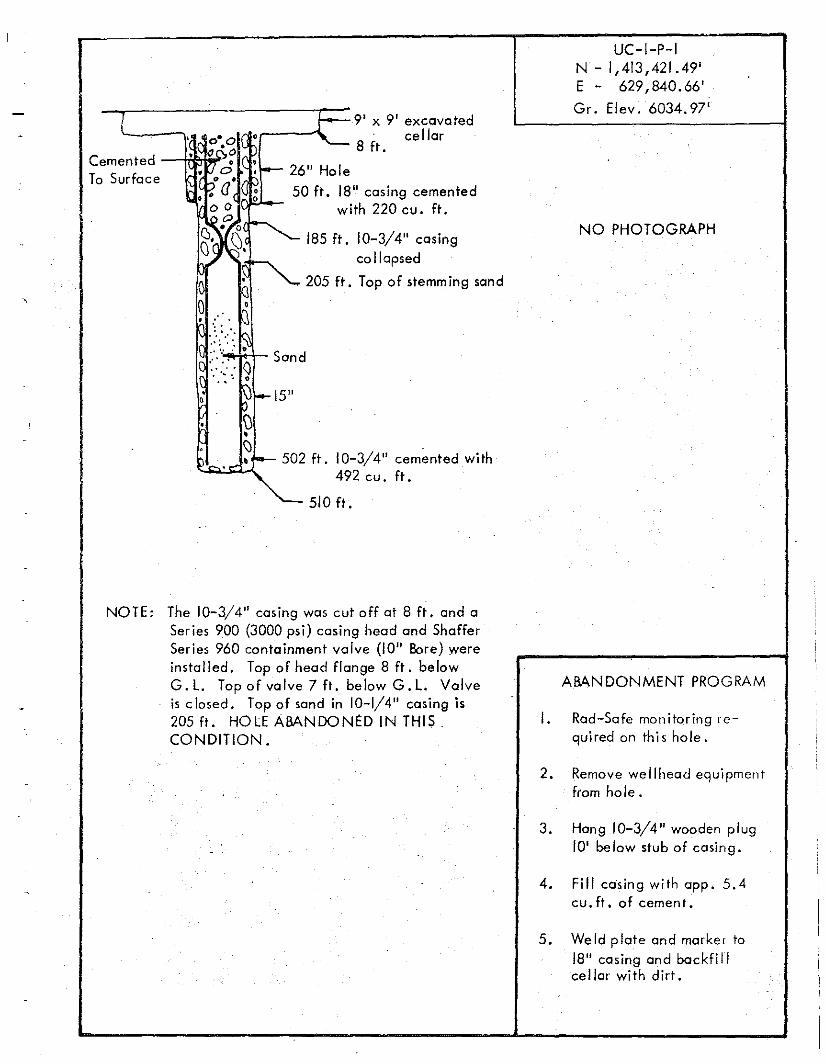
ICementedTo Surface
F 9' X 9' excavated. 0·0 ,~--"" 8' cellar• 100.0 ft..'(10 :- 26" Hole
")0 •. ' a(~ 50 ft. 18" casing cementedo g with 220 cu. ft.
~x~.~ 185 ft. 10-3/4" casingcollapsed
205 ft. Top of stemming sand
o .~• ':: ' ,
.. "'K::: :.. ':' ~
.o
510 ft.
UC-I-P-IN - 1,413,421.49'E - 629,840. 66'
Gr. Elev. 6034.97'
NO PHOTOGRAPH
NOTE: The 10-3/4" casing was cut off at 8 ft. and aSeries 900 (3000 psi) casing head and ShafferSeries 960 containment valve (10" Bore) wereinstalled. Top of head flange 8 ft. belowG.L. Top of valve 7ft. belowG.L. Valveis closed . Top of sand in 10-1/4" casing is205 ft. HOLE ABANDONtD IN THIS.CONDITION.
ABANDONMENT PROGRAM
I. Rad-Safe monitoring required on thi s hole.
2. Remove wellhead equipmentfrom hole.
3. Hang 10-3/4" wooden plug10' be low stub of casing.
4. FiII casing wi th app. 5.4cu. ft. of cement.
5. Weld plate and marker to18" casing and backfillcellar with dirt.
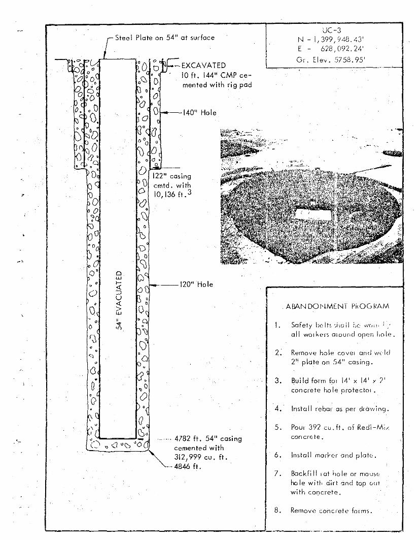
Steel Plate on 54" at surface
".~
......
I. Safety belts',i,oll Lee ~J(,". :,:all wo rk e rs orour.d open l.o le ,
UC-3N - 1,399,948.43'E - 628,092.24'
Gr. El ev . 5758.95'
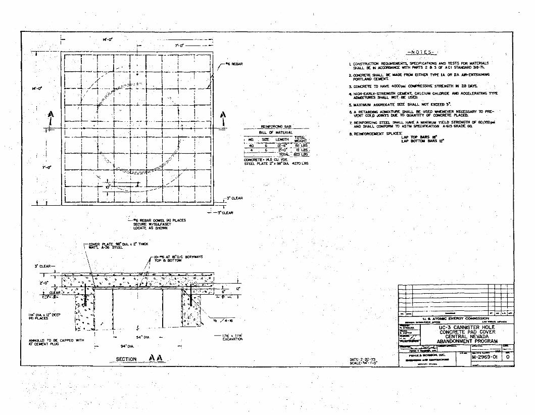
con ere te.
ABA~~DOI'jMtNT PKOGkAM
2: Remove hole covel and wc·ld2 11 plate on 5411 casing.
4.' Install rebar as per drawing.
3. Build form fOI 14' x 14' y 2'concrete hole protector •
5. Pour 392 cu. ft. of Redi-M>
7. Backfi II I at ho Ie or rnouscho Ie with dirt and top ou t
with c oricre t e .
6. Install rnorl er and plate.
122" casingcmtd. withIO,136ft. 3
1---140" Hole
'..- 4782 ft. 54" casingcemented with
" 312,999 cu. ft."'---- 4846 ft.
~1-_--120" Hole
.'
o
o00 ~L--EXCAVATED, 0
, 10 ft. 144" CMP c e-'00, 0 men ted with rig pad
Q' 0w
"c .....«
0 :JU
• «\) >w
0'<t0 <r)
(00 ,<,
0
7
8. Remove concrete forms.
~ --J~ . __, ~ ~
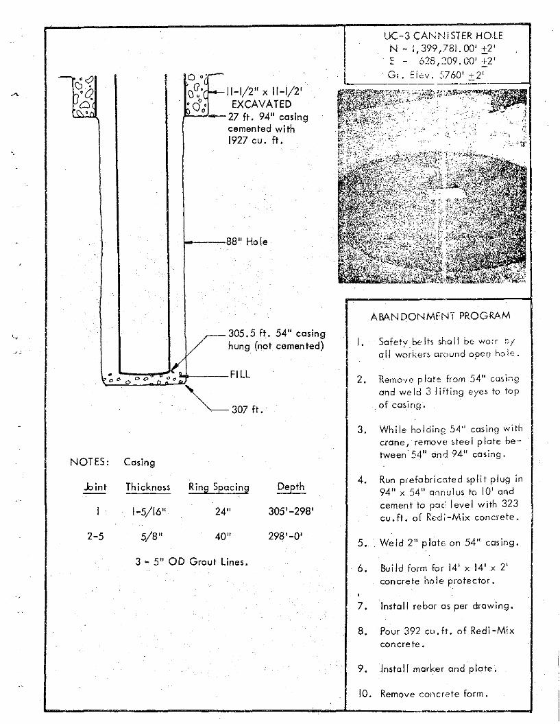
a 'c"'-,R:C'-II-I/2" x 11-1/2'~cJ.; EXCAVATED~-27 ft. 94" casing
cemented with1927 cu. ft.
1-~~~88" Hole
'.
UC-3 CAr-.;~mTERHOLEN - 1,399,781.00' ±.2'~ '?8 ')09 U"O' '2'~ - 0_,- 1"- • - J :!.
,~, "I" '760" 2'\,,;;11 ..... cV . ..' .:r::.--~----I
ABANDONMENT PROGRAM
I ~ 305.5 ft. 54" casing1/ hung (not cemented)
b~ o....o...o..,..."'.....,.;~oK~ FILL
~307ft.
I. Safety be Its sha II be 'worr "Iall worker> around open hole.
Remove p late from 54" casingand weld 3 lifting eyes to topof casing'.
NOTES: Casing
..bint Thickness Ring Spec ing Depth
1-5/16" 24" 305'-298'
2-5 5/8" 40" 298'-0'
3 - 5" 00 Grout Lines.
3. While ho lding 54" casing withcrane, rernove steel plate between' 54" and 94" casing.
4. Run prefabricated split plug in94" x 54" onnulus to 10' andcement to po c. level with 323cu.Ft , of Redi-Mix concrete.
5. Weld 2" plate on 54" casing.
6. SuiId form for 14' x 14' x 2'concrete hole protector.
7. Install rebar as per drawing.
8. Pour 392 cu.ft. of Redi-Mixconcrete.
9 • Install marker and plate.
10. Remove concrete form ...... ..L. .~ .."
Nr~-26" Hole
60 ft. 20" casing cemented~'-with 241 cu. ft .
( ' -. v • I" I, .{j J.
" {I ', "I . 1 ~
. " (
• I I,
, !
//rI
·1I\,,,
.' ••• ' ' 0
:. '::", :
. "
"1;:;"",
lL .
·ll~.. ' J).
T
-IL'~I ~"
1101"
IOOg fl. 13-3/g"·~;:// 'o',i,,<'(j-In' 1,1, d will) :;:~ II} c.:) , P.
I/'I/~" 11"1,,
:1tH:H fl. Pluqqr.r! ell'plll(I Prill '11 f)
4699 fl. 0, iginal Ho lc-
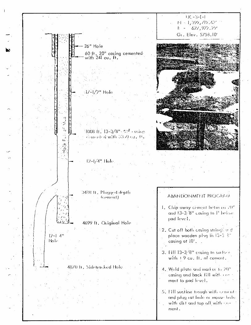
I J( ·:;-H["-I - II:~I/I,/PJ.(J;)'
E· 6/1,9/1./'/'
G,. Elev. 575.3.10'
I. Clrip uwny U·HH..-n t hpl't/( L'II :'(1"
crud 13-3/8" t,(l:,ill~J 10 II IH'I.)~·-:
pan lcvc- I.
2. Cut off boll, eosin') ;!linT.· 'OJ'"
place wooden p lrq ii, 1:;-:; ,.'casing alia'.
I\j
3. fill 13-3/8" eminn 10 ;u,he<
wflh I 9 cu. fl. of cem<:nt.
4. Wf:ld p lcto /m d rrl(ll~t:1 r.. Ir;"casing and bock fill Vlitl , t ->rnent 10 pad lcvc l .
!)~ l i l l suc.t ion 11nuqh w i ll, '.(·rlll"111·
ond pluq 101 ho l« Ol ruou:«- f)f)\r:w ith uil I Clnu lop ofr. will, ','"mont •
- o ·.·.·:·h. ,.~-,
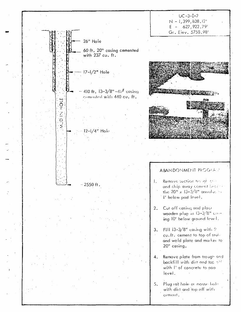
26" Hole
UC-3-1-2N - 1,399,838. i2'E - 627,922.79'Gr. Elev , 5758.98'
o •
o •- 60 ft. 20" casing cemented
with 237 cu. ft.
. UJ.·. --'.0,:r '.'/ .'0'"J
. 2:" :
-
-
--- 17-1/2" Hole
-, 410 ft. 13-3/8" -,tLiIl cosinq
':'·n"."tr·d wiill 440 cu. ft .
12-1/4" Hoi"
- 2550 ft.I. Remov(.: :.ucr;()(: Ii'": !,?~ r.:r ,
and chip O'N(]! r_(;rnr·r.t ;)1':.
t~le 20 11 x 13-3/2,'1 cmnol.r.
I' below pod lr-vcl .
2. Cut off ccrsin q and piau
d I I' , J' '0"woo ~n P u~! III J- .--:U C;j"-
ing 10' below ground [r-vcl .
3. Fill 13-3/8" cming witl. ~:
cu.ft. cement to top of s t uiand weld plate and rnorke r to
20" casing.
4. Remove plate from traugl' andbackfill '"ith dirt and tor; c,:;
with I' of concrete to no olevel.
5. Plug ro] half' O! r:10U~l' fail,·with did and top off wiJl,cr-mon t •
III
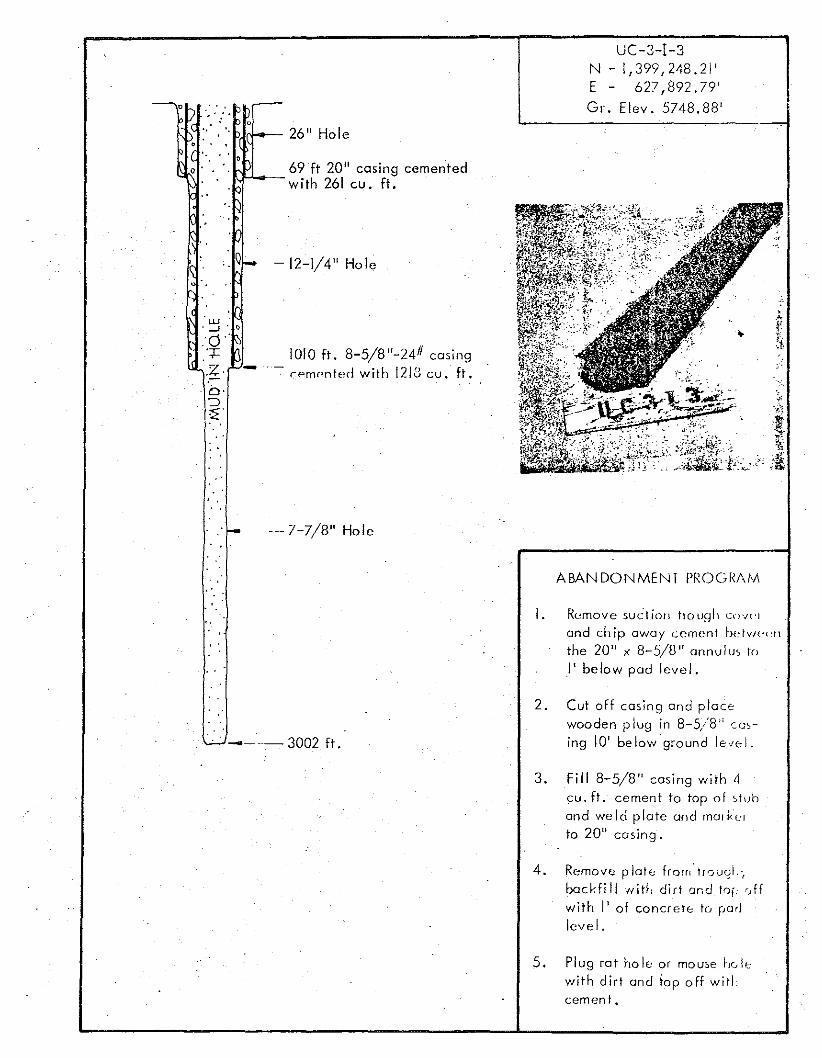
c
o
"lJJr-l-- 26" Hole. . ." .'
o • • •» ....._ 69ft 20" casing cementedwith 26\ cu. ft.
UC-3-1-3N - 1,399,248.21'E - 627,892 ,79'
Gr. Elev. 5748.88'
Q
'w. -l . l)
'0"':j:.
'.2.b·"=:JZ
- 12-1/4" Hole
1010 ft. 8-5/8"-24# casing-, - c ernonted with 1213 cu. ft.
--- 7-7/8" Hole
ABANDONMENT PROGRAM
I. Rernov« suc lion ho uql: COVl'j
and chip away cement be·tv/('{·1tthe 20" x 8-5/8" annulu; to
I' below pad level.
----3002 ft.
2. Cut off casing and placewooden p lug in 8-5/8" c cs-:ing 10' be lowqround le""I.
3. Fill 8-5/8" casing with 4cu. ft. cement to top of st uband weld plate and mot kor
to 20" casing.
4. Remove plott.: from'trQvqf.·(
bacHil1 Hitl, dirt and to\,-,ffwith I' of concrete to i,adlevel.
5. Plug rat ho IE: or mouse ho i,"with dirt and fop off witlcement.
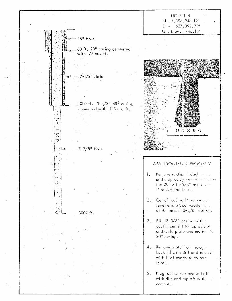
:> ': -.' ..- 28" Hole
UC-3-1-4N - IJ393/948.i2'E - 627; 892 .7')'Gr. E!ev. 5746.15'
-----
) .' _ ...._ 60 ft. 20" cas ing cemen tedwith 177 cu. ft.
to ,,' • l)
" .
• u..J •.....J
'0II
.Z
'0'. ),
~.
-
-17-1/2" Hole
~1005 ft. 1:I-J/H"-4SI1 cusillULPtl\('lltl·d with 11:35 cu. ft .
.. -7-7/8" Hole
I.
.:~ i 4
Rcmo I'~ ':;ljl_ti()rl trr..J'Y;~
and 'Jlip rJ/rJ/ r.r.<'",{;f.r
I ')( 11 "I "J . r ".,f IE: L,j / J- ~/ --:: ")' .r,
- - 3002 ft.
2. Cut off r/.l'~if!(; I' L;~ l-, /I ~,-;-_
le'lel and pia ..::.t: -II:.J ':....-::1:..: , ;, ,
at 101 inside: \3-j./8" '":.0',>.-:.
3. Fill 13-3/8" cOOIng uiHcu. ft. cemer.: teJ top of .~~.)~.
and YIeld plate and rTlo!h·· !:
20" casing.
4. Remove plate from tro,p:!"
backfill Vlit l·, dirt and to," "."with I' of cor.cr e te to per:level.
5. Plug lot hoi" or mouse l.o l:with dirt and topoff v.j tl .CC{T1<'nt.
-26" Hole
- 40 ft. 13-3/8"-48# casingcemented with 178 cu. ft.
~- 12-1/4" Hole
'--~J_ - 360 ft •
RETlJKN TO OOEINV TECHNICAL INFUHNI/'\ i'IUNRESOURCE CENTER
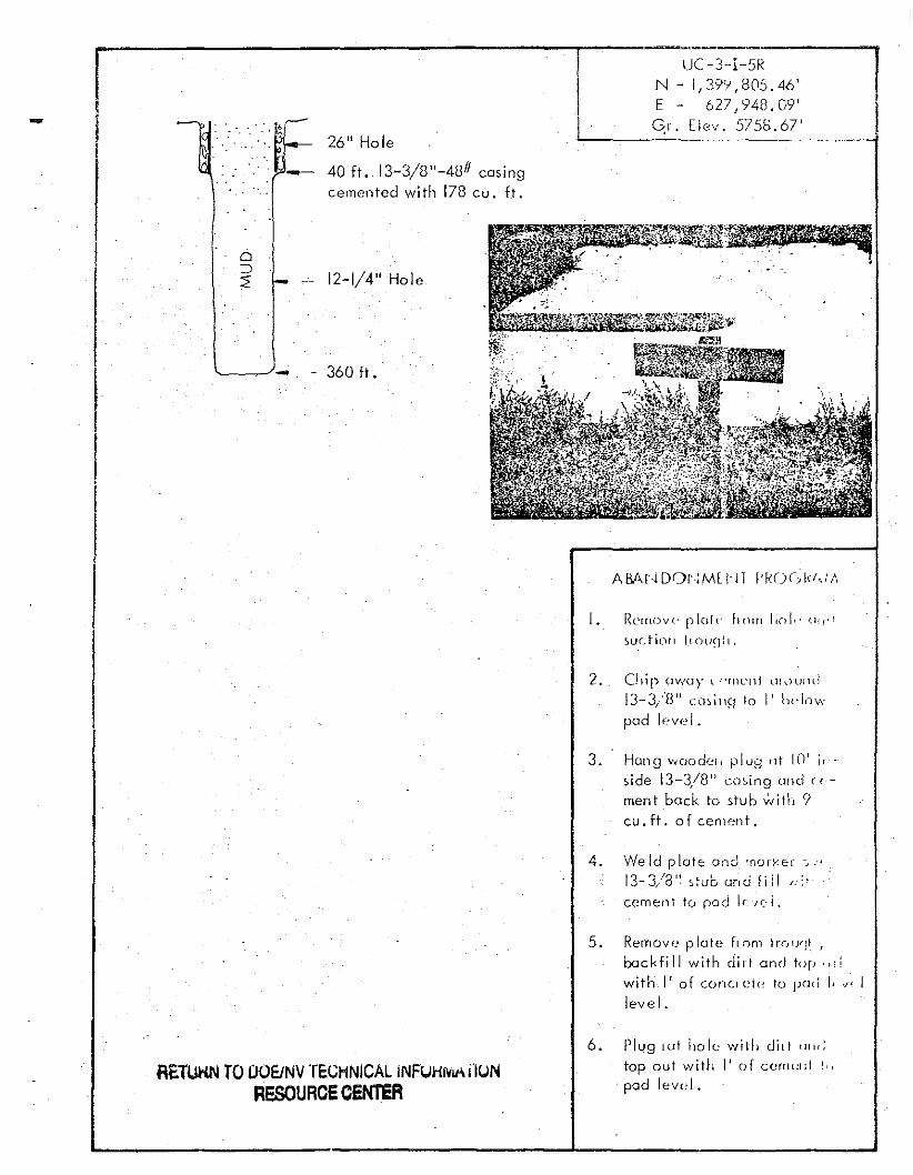
UC -3--I-5RN - 1,39'1,805.46'E - 627,948.09'~I. Elev. 5755.67'L-- '--
I. Rc'rnovl.· p lul r- h om 11\l!,·(lf."!'
~U.cti()fl 1.\ nunll.
2. CJ1ir OWU}' t ,-'rtll'lli W(HJlIlI13-3/8 1J
CCl'1ill~J 10 I' lH'Jowpad "'ve I .
3. Hang v,00d0', plug ut 10' j,
side 13-3/8" cosing ond c i
ment back to stub with 9cu. ft. of cement.
4. Weld p lct e o nd -norv er -•."13-3/81~ stub and f ii l I.;"
cement to pod IC/.;i.
5. Remove p late from trrJ!Jf]1 I
backfill with dirt and top ,"~
with]' of co nci c tr- to [Jot! [, 'I'~ Ilevel.
6. Plug rat ho lc wilh did utn,
top out witll I' of cern{~td !.,
pad leve l .
IiII!
;:.' '
" '.' ..
'. '· . '.
I .:
,'/ .
-~4 .----,
I'~ - 1,430,564.49' .. '. IE - 628.253,40' . I
Gr. t lev. Not AV::li lcbie'----_._-----.---
II!
I
.., ."
" .. . ." .
.' "l.,I..f.".' -"0
I
Z
o~
:E
120" Hole
I. Safety be Its she II be worn b Iall workers "round open hole.
, ': ..
',' ,
.. ,
. "...'· ..... '"
'.' ..
2. Remove hole cover and weld2" plate on 122" casing.
3. Build form for 14' x 14' x 2'concrete hole protector.
4. Install rebar cs per drawing .
5.. Pour 392 cu.ft. of Redi-Mixconcrete.
6. Install marker and plate.
· ,', '. "
-" '.... . '.... '
, . ,.' \ '. '. ' . ~ .'
::'. ":.:":,," I ••• '
. ',' ... . . , . ". ' . ..7. Backfi II rat ho.le or mouse
hale with dirt and top outwith concrete .
8. Remove form.
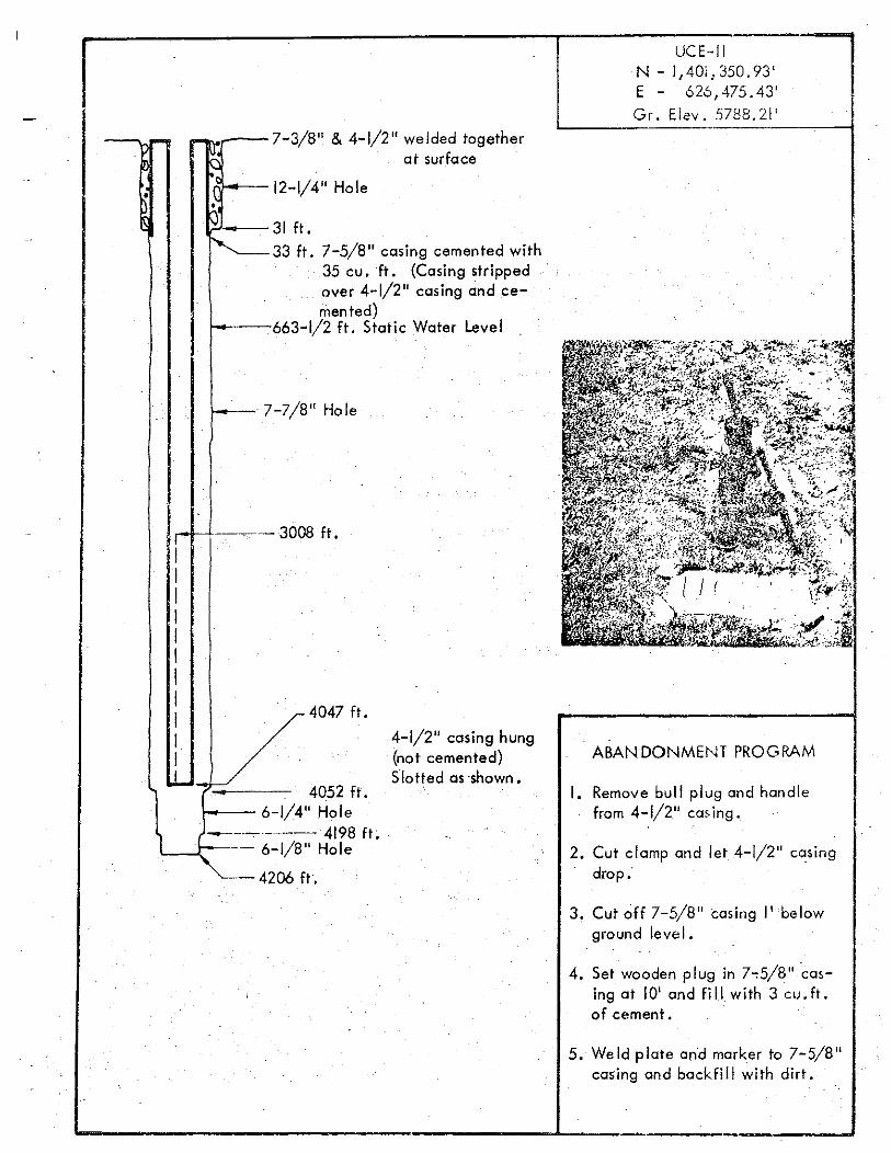
UCE-IIN - 1,40i,350.93'E - 626,475.43'Gr. Elev. 5788.21'
nr--12-1/4" Hole
7-5/8" casing cemented with35 cu. ft. (Casing strippedover 4-1/2" casing and cemented)
f----663-1/2 ft. Static Water Level
~~.~A'JrJ--__ 31 ft
~33ft.
-
I
•
4047 ft.
f--_. 7-7/8" Hole
1,----·-3008 ft.
IIIIIIIIIIII
• 4052 ft.t--- 6-1/4" Hole
~ (~_._._--- 4198 ft.11.---\:>----- 6-1/8" Hole
4206 ft.
4-1/2" casing hung(not cemented)Slotted as ·shown.
ABANDONMEt'H PROGRAM
I. Remove bull plug and handlefrom 4-1/2" cas ing.
2. Cut clamp and let 4-1/2" casingdrop:
3. Cut off 7~5/8" casing I' belowground level.
4. Set wooden plug in 7~5/8" casing at 10' and fi II with 3 cu. ft.of cement.
5. Weld plate and marker to 7-5/8"casing and bockfi II with dirt.
UCE-18
UCE-18 in the northern part of Hot Cr~ek Valley was drilled to 6514' encountering
4090' of alluvium, 115' of tuffaceous sediments, 175' of lake beds and gypsum,
2064' of rhyolite, and 70' of tuff.
A pro lific water producing zone from approximately 5530 feet to 5915 feet
(fractured rhyolite) has a static water level approximately 190 feet below ground
level. The water from this deep zone has more dissolved solids (including a
higher percent of natural radioactive material) than the shallow alluvium. The
open shollow zone ot 406 feet to 598 feet (alluvium) has a static water level
330 feet be'low ground level. It is possible that the undes ircble water from the
prolific lower zone moy migrate upward into the, shallow alluvium through the
p"Jfo,otions from 40b f"et to 598 feet. Sec Pages 20-24 of USGS Central
Novoacr - 23.
The water from the deeper zone can be shut outof the upper alluvium by a plug
below 600 feet. A plug below 1500 feet would increase the reliability of the
seal if the uncemented section of 9-5/8 inch casing becomes parted at some
future time.
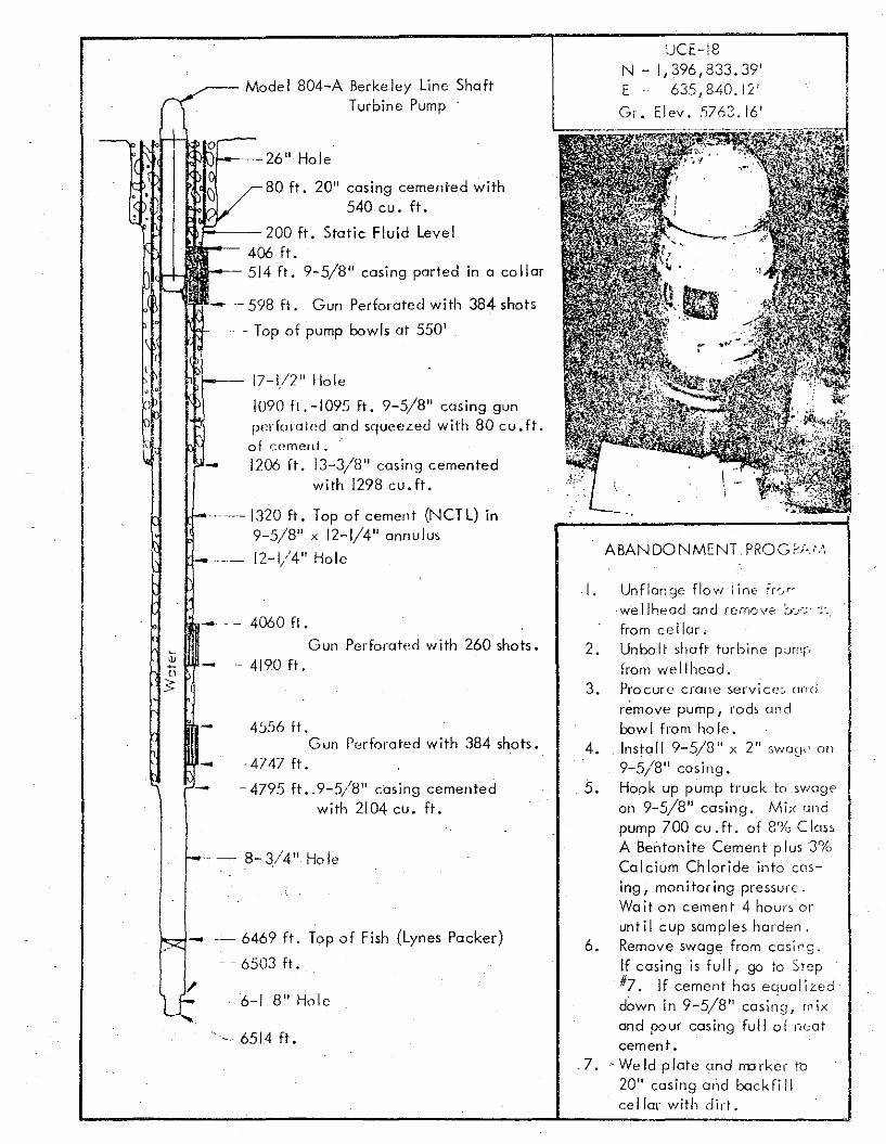
CJCH8N - 1,396,833.39'E - 635,840. 12'
El ev , 5763.16'
ABANDONMENT PROG,,;'J:',
Mode I 804-A Berke ley Line Sha ftTurbine Pump
a
r--- 17-1/2" Hole
1090 fl. -1095 ft. 9-5/8" casing gunf'"rfoldled and squeezed with 80 cu. ft.of cement ~
- 1206 ft. 13-3/8" casing cementedwith 1298 cu. ft.
'·---1320 ft. Top of cement (NeTL) in9-5/8" x 12-1/4" annulus
12-1/4" Hole
mll:1l---26" Hole
80 ft. 20" casing cemented with540 cu. ft.
~-- 200 ft. Static Fluid Level406 ft.
- 514 ft. 9-5/8" casing parted in a collar
- 598 ft. Gun Perforated with 384 shots
- Top of pump bowls at 550'
I
!
I- . - 4060 ft.
Gun Perforated with 260 shots.-- 4190 ft.
4556 ft.Gun Perforated with 384 shots.
- -4747 ft.
- - 4795 ft. 9-5/8" casing cementedwith 2104 cu. ft.
8-3/4" Hole
_ '- 6469 ft. Top of Fish (Lynes Packer)
- - 6503 ft.
6-18" Hole
-,- 6514 ft.
2.
3.
4.
5.
6.
7.
Unflonge flow line ir",c-we Ilheod and remove C>o';
from cellar.Unbolt shaft turbine pJrnr,
from wellhead.Procure crane servi c e.. (lnel
remove pump I rods cmdbow I from ho Ie.Install 9-5/8 11 x 2 11
SW(j~F' on
9-5/8" casing.Hook up pump truck to swagean 9-5/8" casing. Mix andpump 700 cu. ft. of 8% ClossA Bentonite Cement plus 3%Calcium Chloride into cm
ing, monitoring pressure.Wait on cement 4 hours oruntil cup samples harden.Remove swcqe from casing.
If casing is full, go to Step#7. If cement has equalizeddown in 9-5/8" casing! rnixand pour casing full of n"atcement •
. We Id p late and rrn rker to20" casing 0I1d bockfillce 11m with dirt ,
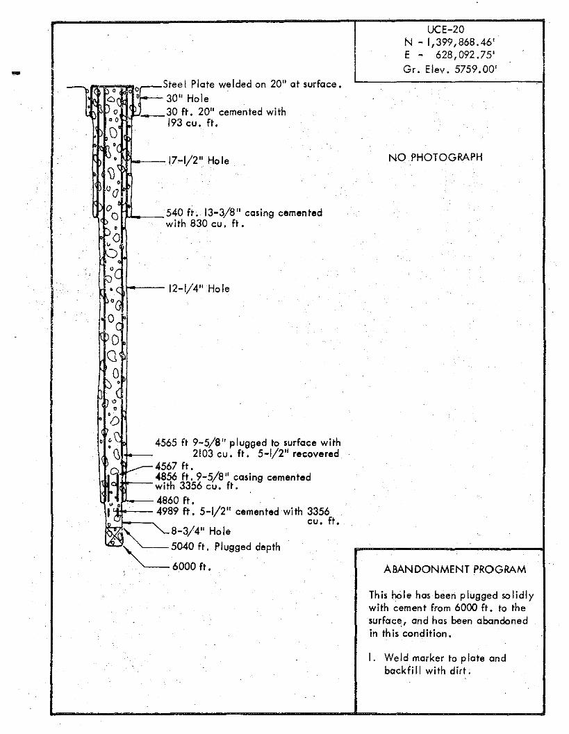
UCE-20N - 1,399,868.46'E - 628,092.75'
IGr. Elev. 5759.00'
- cSteel Plate welded on 20" at surface.o
D; [ 30" Hole~30 ft. 20" cemented with
00 193 cu. ft.\)
11 '(NQ PHOTOGRAPH~, 17-1/2" Hole
'\)\0
°00 540 ft. 13-3/8" casing cementedoPo with 830 cu. ft.
0'..;c~( 12-1/4" HoleI O(
°c0
Q
00 0
,,(0
'0o <~ 4565 ft 9-5/8" plugged to surface witho\) 2103 cu. ft. 5-1/2" recovered
t---4567 ft. .~ 4856 ft. 9-5/8" casing cemented
with 3356 cu. ft.•. 4860 ft. . .I'J' 4989 ft. 5-1/2" cemented with 3356~ cu. ft.
8-3/4" Hole
'~~5040 ft. Plugged depth'
. 6000 ft. ABANDONMENT PROGRAM
This hOle has been plugged solidlywith cement from 6000 ft. to thesurfece , and has been abandonedin th is condition.
I. Weld marker to plate andbackfill with dirt.
,
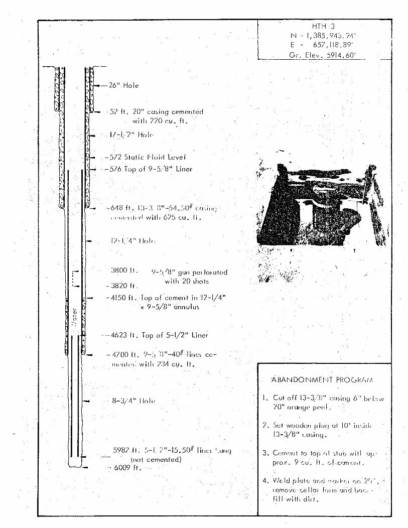
HTH-3N .. 1,385,943.'14'E - 657,118.39'
Gr. Elev. 5914.60'L..--'----=-'-'-' _
--26" Hole
, '1 .
-~5l ft. 20 ll c csinq cemented
wi lit 770 cu. ft.
,:t, ;.'!;:'. -.
i~:~j:::;'.:.' 1~~?~;JY"'J-!>/8 11 gun PCI for c tod
willt 20 shots
Top o(cement in 12-1/4"x 9-5/8" annulus
Ii'-I,'~" 11"1,,
,.6-18 ft. I:{-J i)lI-!j;j.~,OII C{J·.ill~;
l"t'ld,'llkd willI 625 cu. II ..
:JHOO II,
- 3820 fl ,
-4150 fl.
-572 Siotic FllJid Level
-576 Top of 9-5/8" Liner
e
-
,,,,'-
---4623 ft. Top of 5-1/2" Line;'
- 4100 fl. ')-". "3"-4011,I illCcl C<:
fllt'llkl: willi /34 cu .. ft.
- 8-J/I1° link·
ABN~DONMHH PROGI,U/,
I. Cui off 13-3/,)" cos inq 6" b"l:0",20 11 oronqo pocl .
'2. Sut wooden pluq of 10' in',icll
13-3/8" c.csinq ,
5982 fl. ~)-1. ~)I'-15.5011 IiIlC'1 ; . lJlI 91.1101 cemented)
'- 6009 fl.
3. Cernrml to fop nf '..tub '/lit! fJ!;
prox , ? suo ft. :)fCf.m(~I,I.
4. VIe: ld pl'J!'=: rJrrrJ '(,rjr h:l r;fj' /!(/' I
rerno ve. c.ellar {or rn fJnrJ bur>fill witL di,".
!-- 26" Hole
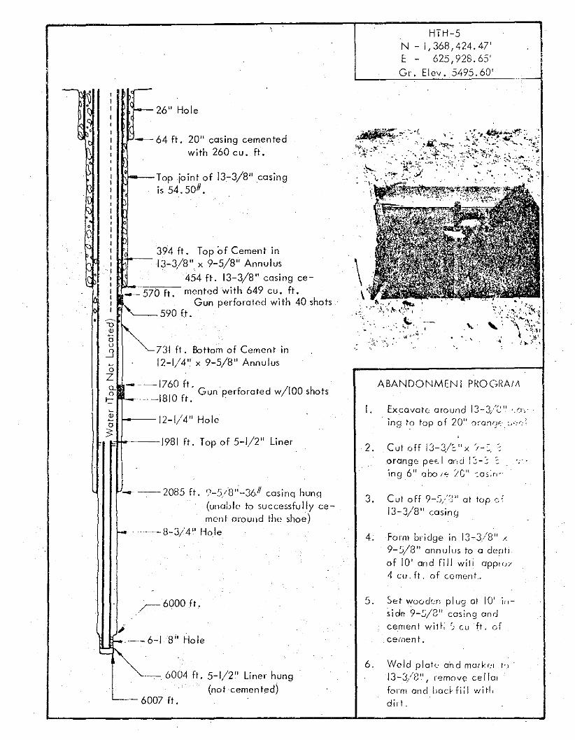
HTH-5N - 1,368,424.47'E - 625, 928. 65'Gr. Elev. 5495.60'
2. _Cut off 13-3/~I'x :"-=, ~
orange p ee l and !>~ :;ing 6 11 abo if; iG11 :0:;';11'
ABANDONMENT PROGRAIJI
. ~-, .. ~-
I. ExcavatE.: around 13-3/2 11;JJ",.
ing t? top 0 f 20 11C)~-anr~",.· :-,'-:': I
\
,-,
- -·-1760 ft.Gun perforated w/IOO shots
~-..-1810 ft. -
~."'---731 ft. Bottom of Cement in
12-1/4" x 9-5/8" Annulus
"",--Top joint of 13-3/8" casingis 54.50#.
-
- 64 ft. 20" casing cementedwith 260 cu. ft.
~
2 12-1/4" Holea '
3: j..---1981 ft. Top of 5-1/2" Liner
aZg-
C
e
.•
-- --- 2085 ft. '.'-5/8"-3&11 eosinq huno(unable to successfully cemen t around the shoe)
I- . ·--8-3/4" Hole
3. Cut off 9-:),i~J" at tup d13-3/8" casing
4. Form bridge in 13~3./81r /.9-5/8" annulus to a derrti
of 10' and fill wit i appl"Y4 cu. ft. of cement,
r-6000 ft.
,1--- 6-18" Hole
~~.- 6004 ft. 5-1/2" Liner hung
(not cemented)L-_ 6007 ft.
5. Set woo der. plug or IU In
side 9-.s/2 11 casing andcement wi t l. S eu ft. cf
cemen t .
6. Weld plate and mor kr-t t-v :
13-3/8 1l, remove cello!
form and Lac~fi;1 wid!
dirt .
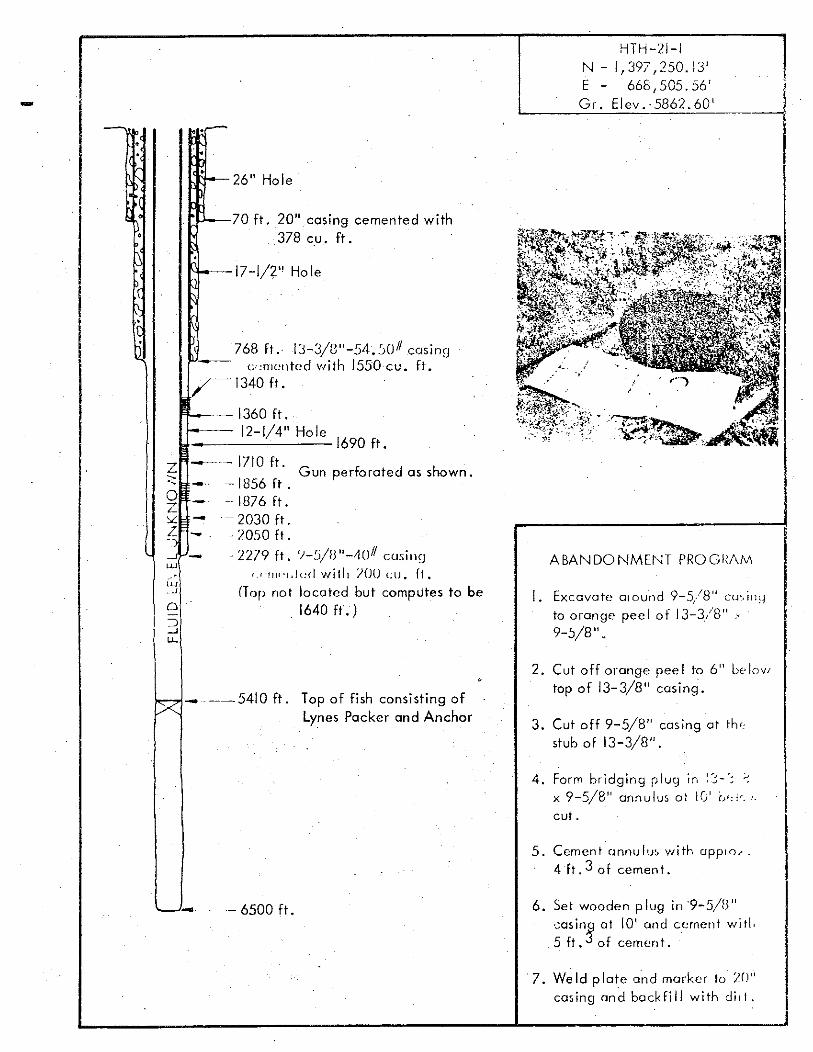
-HTH-21-1
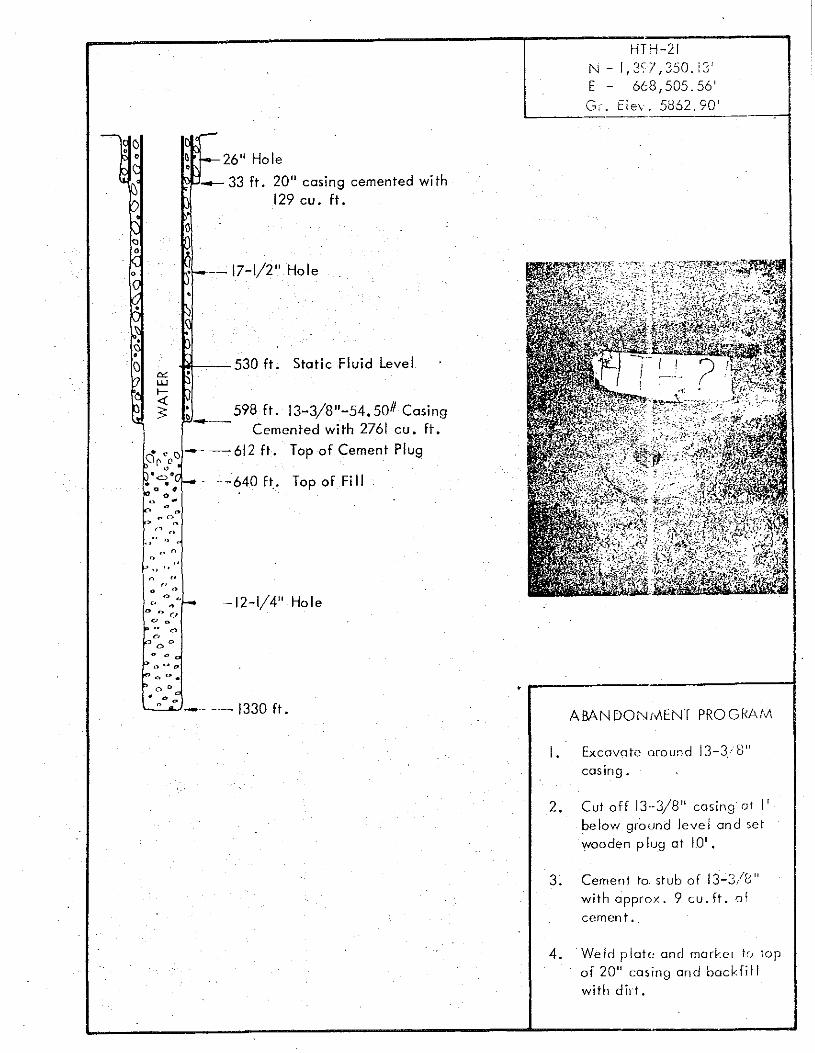
N - 1,397,250.13'E - 668,505.56'Gr. Elev.·5862.60'
.r--
L'tl-26" Hole
[~'---70 ft. 20" casing cemented with378 cu. ft.
1'1--17-1/2" Hole
768 ft. 13-J/8"-54.JOII casing--- c.imcntc d with 1550 cu. ft./--1340 ft.
r---- 1360 ft.r:--- 12-1/4" Hole 1690 ft.
. 'IV_.....J _
u.r
9 5 /8 " .I. Excavate cnound -:'. cu-. lll~-~
to orange pee I 0 f 13-3/8" .'9-5/8" .
ABANDONMENT PROGRAiv\
~·-1710 ft.Z Gun perforated as shown.:::; _.. - 1856 ft .Q - 1876 ft.c::L -- 2030 ft.?:: -. 2050 ft.
·2279 ft. ')-~i/B"-4()11 cusingu·/fwl.!(:d willi )()O cu • fl .
(Top not loco ted but computes to be1640 ft.)
~ _---5410 ft. Top of fish consisting ofLynes Packer and Anchor
2. Cut off orange pee 1 to 6" be lov/
top of 13-3/8" casing.
3. Cut off 9-5/8" casing ot th·,stub of 13-3/8".
4. Form bridging plug In :e:-'; ~
x 9-5/8 11 annulus at IU r;&-; !~_-'.
cut.
5. Cement'annulu; with applo?_4 ft. 3 0 f cemen t .
'-- - - -- 6500 ft. 6. Set wooden plug in '9-5/B"·"osin9 at 10' and cement wi tl.5 ft. 3 of cement.
7. We ld plate o'nd marker to 20"casing and backfill with dir t •
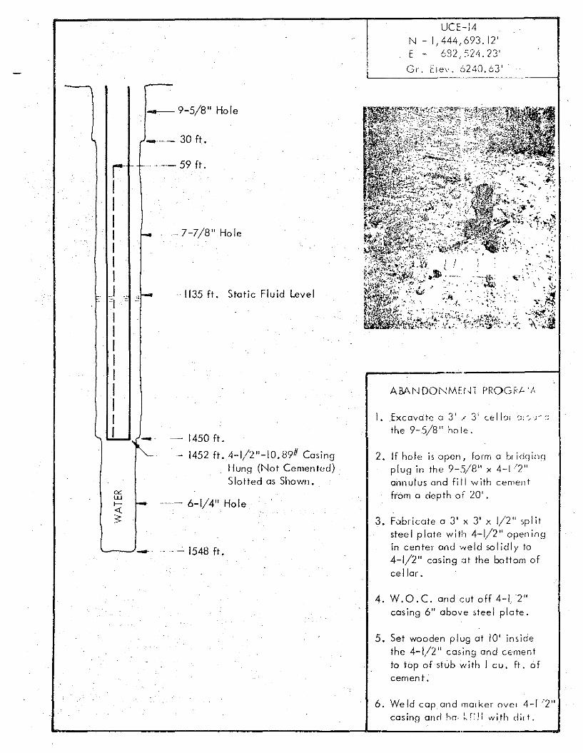
UCH4N - 1,444,693.12'E - 632 524.23'Gr. [lev'. ~)240.631
6-1/4" Hole
2. If hole is open, form a for idq inqplug in the 9-5/8" x 4-1/2"annulus and fiil with cementfrom a depth of 20' .
3. Fubricate a 3' x 3' x 1/2" splitsteel plate with 4-1/2" openingin center and weld solidly to4-1/2" casing at the bottom ofcellar.
I. Excovo te 03' / 3' cel [or a:'"J""
the 9-5/8" ho le .
Static Fluid Level
1450 ft.
1452 ft. 4-1/2"-10.89# CasingHung (Not Cemented)Slotted as Shown.
.. 1135 ft.
-7-7/8" Hole
_-- 30 ft.
· __ 9-5/8" Hole
r f- -- --- 59 ft.
IIIIIII
J ~I-~I -
IIIIII .IIf
'-----'--- - 1548 ft.
4. W.O.c. and cut off 4-1,2"casing 6" above steel plate.
5. Set wooden plug at 10' insidethe 4-1/2" casing and cementto top of stub with I cu. ft. ofcement .
6. We Id cop, and mal ker ov e r 4-1 /2"casing end ho- l.fl l l wUh dit t •
o ". (}
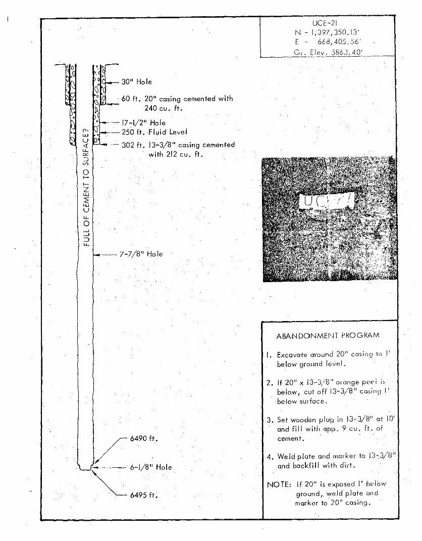
;j\l-...-- 30" Hole\)o 60 ft. 20" casing cemented with'-~ 240 cu. ft.
--17-1/2" Hole~ LV.f~- 250 ft. Fluid LevelU<t ----302 ft. 13-3/8" casing cementedu..ca with 212 cu. ft.~V)
ol-
I-
ZUJ
::EUJ
uu,
o-'-'::::Ju..
---- 7-7/8" Hole
r 6490 ft .•
/-.----- 6-1/8" Hole
~6495ft. .
UCE-21f"-J - 1;397,350.13'E'~ 668,405,56 1
Gr. Elev. 5863.40'L-__--'=- . _
ABANDONMEf,n Pf<OGf<AM
I. Excavate around 20" casing to I'below ground lev"l.
2. If 20" x 13··3/8" olonge pee I "below, cut off 13-3/8" c osinq I'
-below surfcc e .
3. Set wooden plug In 13-3/8" at 10'and fill with app. 9 cu. Ir . ofcement.
4. Weld plate and marker to 13-3/8"and backfill with dirt.
NOTE: If 20" is exposed I' belowground,_ weld plate andmarker to 20" casing.
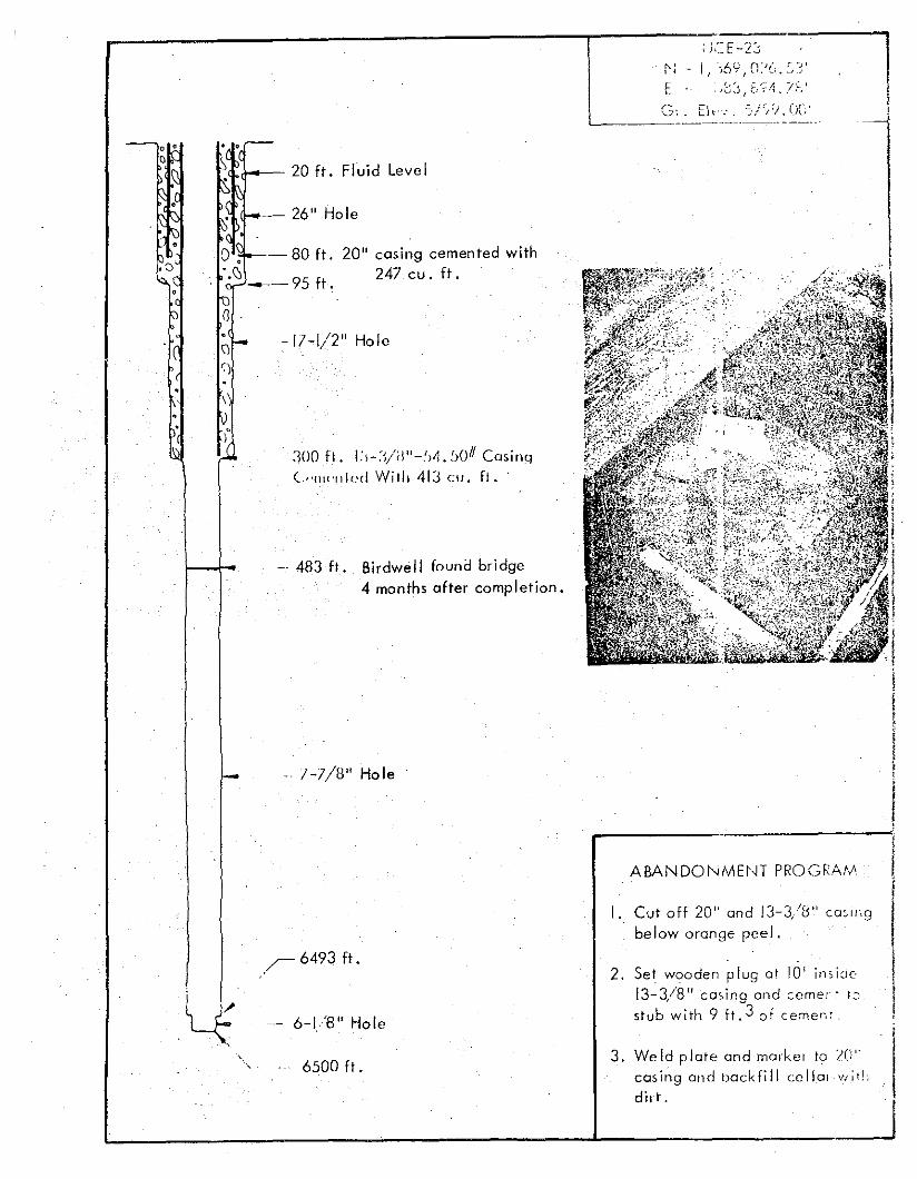
-17-1/2" Hole
lcasing cemented with247 cu. ft.
20"
]00 fl. I:>-:VW'-!)~.!)O" Casinq(."Ilt<'IIIc'c! Willi 413 cu , fl.
-. 483 ft. Birdwell fauna bridge4 months after completion.
• ,r--
f\~ <1--- 20 ft. Fluid LevelK""
~(1.(f-- 26" Hole
~o, 80 ft.
, '.(J 9 f'I c.-~- 5 t ,
IDo'-()
,
I- - 1-7/8" Hole
ABANDONMH,n PROGFAtl'
I., Cutoff 20" and 13-3/8" Casll',gbelow orange peel.
, I4
"
,~6493 ft.
6-1/8" Hole
6500 ft.
2, Set wooden plug at 10' inside13-3/8" cming and cerner: ,."
stub with 9 ft. 3 of c erner.: .
3. Weld plate and marker to 2Cr"casing on d ticck fil l ccllo: wi!!,
dur ,
HTH-21
N - I, 3~7 1 350. i31
E - 668,505,56'G,'. Eiev. 5862.90'
e C>• o, 26" Hole
__ 33 ft. 20" cosine cemented wi th129cu. ft.
"o
-12-1/4" Hole
--640 [r, Top of FiII
-- 17-1/2" Hole
~--530 ft. Static Fluid Level
" ~
o ",. .,., 0. ,.,
o 0'
~ dn
'",0
.. '.
~ 598 ft. 13-3/8"-54,50# Casing--- Cemented with 2761 cu , ff ,
c': C <) -,--- 612 ft. Top of Cement Plue,,~ 0
o'co'• •
o
• 0
" 0• nO co
-- '- 1330 ft. AMNDONrvlENT PROGI<AIv',
I. Excavate mound 13-3,'8"casing.
2. Cut off 13,·3/8" casing o t I',below ground level on d setwooden p lug at 10'.
3. Cement to, stub of 13-3/8"with approx. 9 cu. ft. of
cemen t •
4. We ld p lotr- and morkcr Ie; io pof 20" casing and bockf i IIwith dirt.
'. ,
- " r--, ,
' ..... ~ ... '"
. .. .. ": ': 1---- 12-1/4" Hole. , .' .,.. , ..... '
, '.
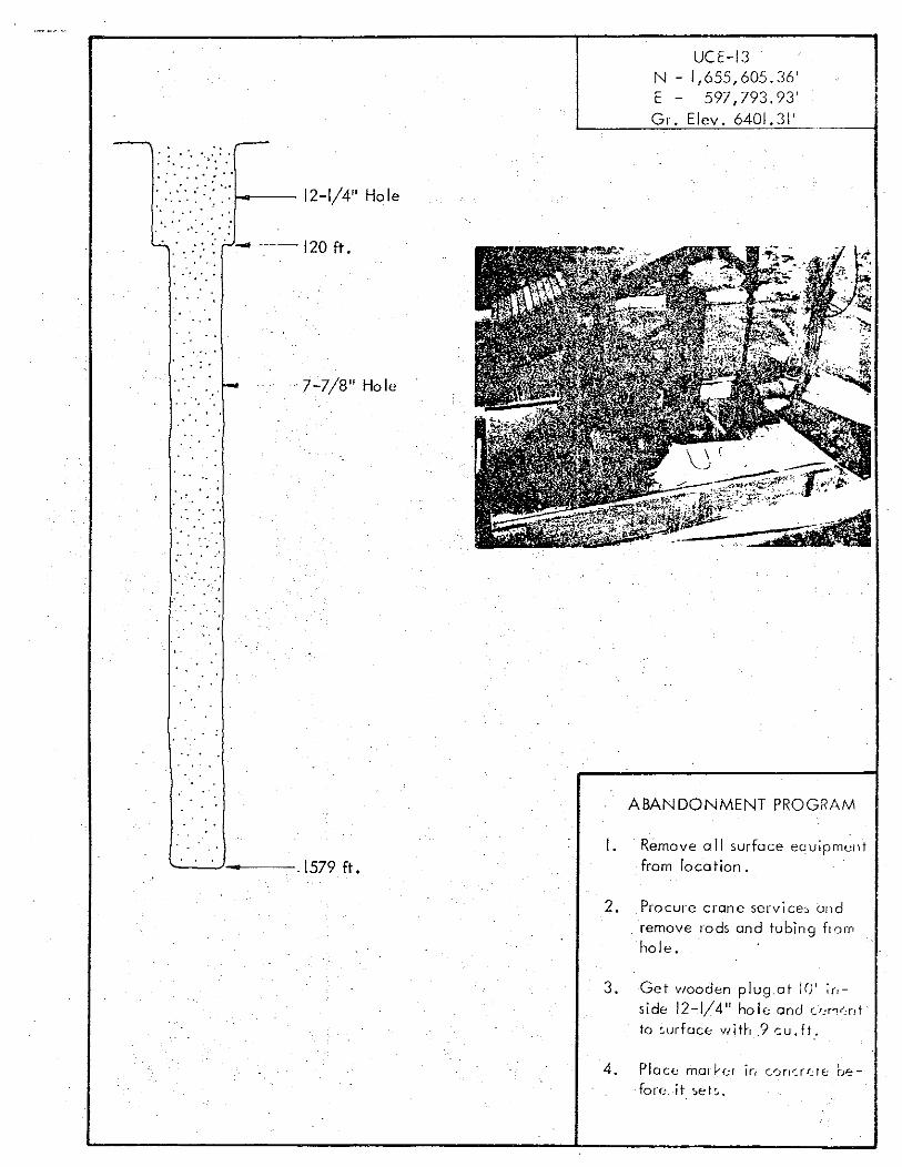
UCE-I3N - 1,655,605.36'E - 597,793.93'Gr. Elev. 6401.31'
L.:. ' • .' ', : ;.....,-.....--- 120 ft.
. ,
", .. : .
,.' • I_. ",r-
...
:.
-7-7/8" Hole
ABANDONMENT PROGRAM
'--~' -----,1579 ft.I. Remove a II surface equipment
from location.
2. Procure crane services on dremove rods and tubing flamhole.
3. Get wooden plug at 10' ;r,side 12...1/4" ho le and u,ro"r,tto ,urfaee with? cu. ft.
4. Plo co rnorl-r-r in C0rl":.rf.:rE; before. it se t s ,
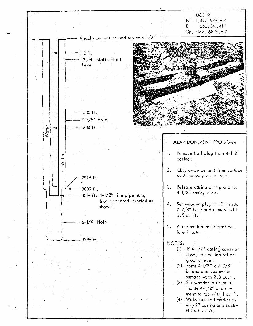
3. Release casing clomp and lei4-1/2" cosirrq drop.
4. Set wooden plug at 10' in';id"7-7/8" hole and cement ~iil,
3.5 cu.ft.
NOTES:(I) If 4-1/2" casing does not
drop, cut casing off atground level.
(2) Form 4-1/2" x 7-7/8"bridge and cement tosurface with 2.3 cu.ft.
(3) Set wooden plug at 10'inside 4-1/2" and cement to top with I cu. fl.
(4) We Id cap and rnorke. to4-1/2" casing and backfill w itliciir't ,
I. Remove bull plug from 4-1 Ycasing.
5. Place marker in cement before it sets.
,2. Chip away cement fran, c,.J' heeto 2' be low ground leve I.
ABANDONMENT PROGRAM
2996 ft.
UCE-9N - 1,477,975.6'1'E - 562,341.41'Gr. Elev. 6879.6:j'
3295 ft.
3009 ft.
3019 ft. 4-1/2" line pipe hung(not cemented) Slotted asshown.
6-1/4" Hole
1530 ft.
7-7/8',0 Hole
1634 ft.
110 ft.
125 ft. Static FluidLevel
4 sacks cement around top of 4-1/2"
.""""""""'"1IIII,IIIIII
I 1---~
Q)
I~
" I3:IIII ~
2I o
I 3:
I I! I
II
-.., .." - •
-
..
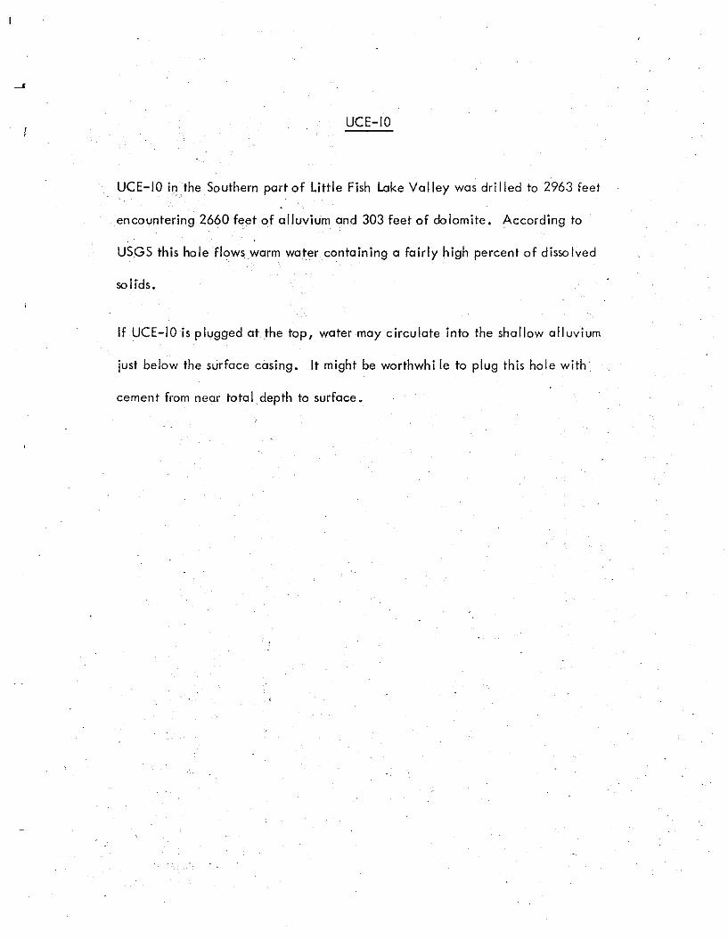
UCE-IO
UCE-IO in the Southern part of Little Fish Lake Valley was dri lied to 2963 feet
encountering 2660 feet ofalluvium and 303 feet of dolomite. According to
USGS this hole flows worm water containing a fairly high percent of dissolved
solids.
If UCE-IOis plugged at the top, water may circulate into the shallow alluvium
just below the surface casing. It might be worthwhi Ie to plug this hole with
cement from near total depth to surface.
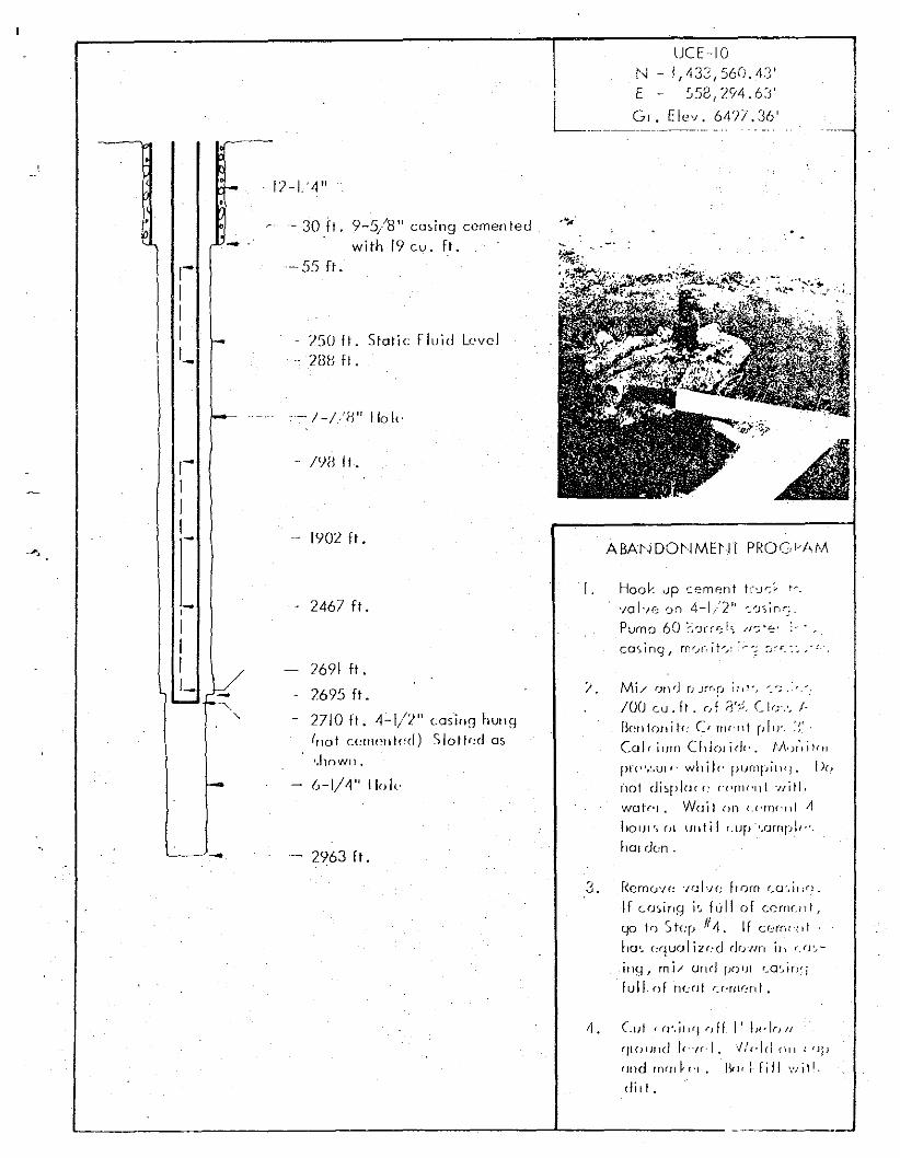
UCHOr...J - !,133,S6(;.4T
, E - ~58,294,6~j'
L G-'._Ele~: ?4?7,_~6'
~- - 30 Ft . 9-5/8" casing eemen led
-- withIgeu.Ft.- 55 ft .
ABA~mO~IME~n PROCi'I\I<A
- I<JB II.
/50 II. Sialic fluid Level28B fl,
- 1902 ft .
"- / _I/B" 1101('
12-L'4"
,-II,
'-
,-,II1- -
-
-- 2467 fl.
2691 ft.
2695 Ft.
- 2710 fl. 4-1/L" casing hun9(nol c"lII"nl<,d) Slotl"d 05
<hown •
6-1/4" Ilok
-- 2963 fl.
l . Hoo k up cement t(,J":'~ r-.
volve 0Tl 4-1/2 11-:"'JSln.',,:.
Pump 60 ~>-Jl"r€:is :I';'~'
casing, rn .....J(,it,...... : ~;u:.:.~_-:.
? Mi/ r;nd rJ Jrr'~J i nt-. "',r...: ,"-,
100 cu . It , r,f ij"", (I,J',', /.Bml!oflih: C, rrH"1l1 pill'. ~~'.
Ccl cium Cillolidt" f.!\<)r\;!(11
pr<",~.Ul/· whilr- purnpi\l'J. D(!
1101 di~pl(J( t : c.c-mr-u l -vi tl .
wotr-r • Woi I on u'rrlt'rd J1
lrour-, (ll unt i l LlJp·'.ornrJI,·'.
hal don .
3. Remove P;[-'/0 [r om CG'..u.o.
If c osinq i ... full of cement f
go 10 St<:p IIJi. If com.n '
hc-, r.quo l iz od drJlJrt ill r:JJ'.,
inq 1 rni/ onrl fJOI)1 r_a':.ir-l~;
full of norr! c r-mr-nt..
/l • Cut i fJ',i/l'J f) ff ! t !J"!f} 1/
'j[Ol)lJd !f·,{,·I. 'fIeld (i! I , 'lfJ
(J"d rncll~'" I... I rill v-i tl .eli" .
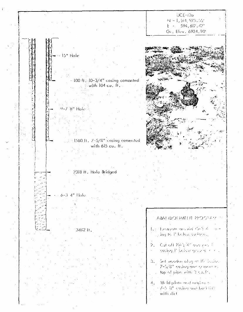
~)CE-iL(J
E 594,617.47'G,. EIe-v. 6974.90'
I!JUOI! . 1-5/8 l 1 cas inC) ccrneu tod
with 615 cu. It.
2318 II. Hole Bridged
··100 F! ; 0-3/4" casing cementedwith 104 cu. ft.
I, ,l-~-I : .•1~ '-.~ i
r '.'
'I,. ,~ i,>J!"I
!" 'I-I" -,. ,
t1' ..[I'i'
f l"'.I.t'
\
I,;1
l-t1.; ~ 1_I l) ~. I:," Hole
I '~~~ I, .l i --
~ '\
~
!.' L/'.u/'Jtt fJf', Jf:d I")-'~ /,
infj If, j I L,; if, r, ',"Y ";'-':.
•j:o---36ft.
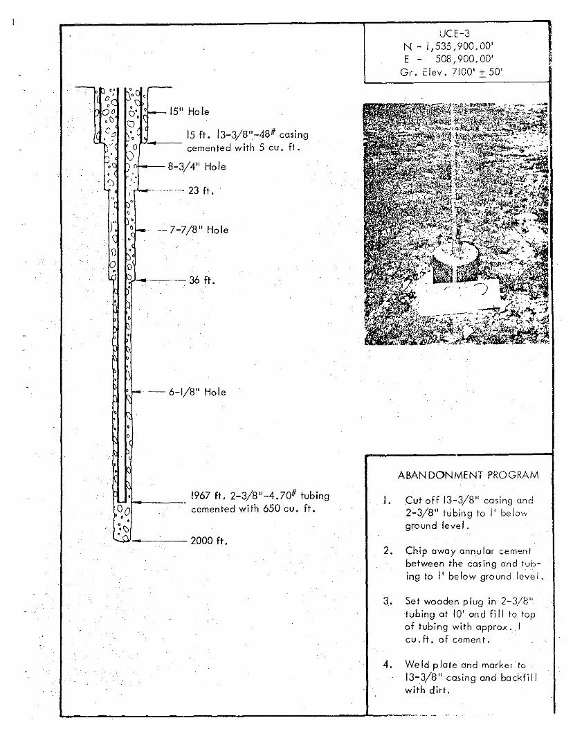
UCE-3N - i ,535,900. 00'E - 508,900.00'
Gr. clev. 7100' :!:. 50'
Or r-j" 0
01:Q' 0 15" Hole•Cl
.Cq p',. 15 ft. 13-3/8"-48# casing~.. oP.---- cemented with 5 cu. ft.~. ;)~Q bor--- 8-3/4" Hole, .f) I'·
r'-o----- -- 23 ft.
fJ"'.•
j~ .•~-- --7-7/8" Hole
\Jc,.,~
r"" - 6-1/8" Hole
o
ABANDONMENT PROGRAM
I,
1967 ft. 2-3/8"-4.70# tubing001----- cemented with 650 cu. ft.
e ,~\)GC\J ..
I. Cut off 13-3/8" casing and2-3/8" tubing to I' belowground level.
2. Chip away annular cemenibetween the casing arid tub
ing to I' below ground level.
3. Set wooden plug in 2-3/8"tubing ot 10' ond fi II to topof tubing with opprox . Icu. ft. of cemen t ,
4. Weld plate and rnorke i to13-.3/8" casing and backfillwith dirt.
L..- ....... -
• 0
•
•
•o ••
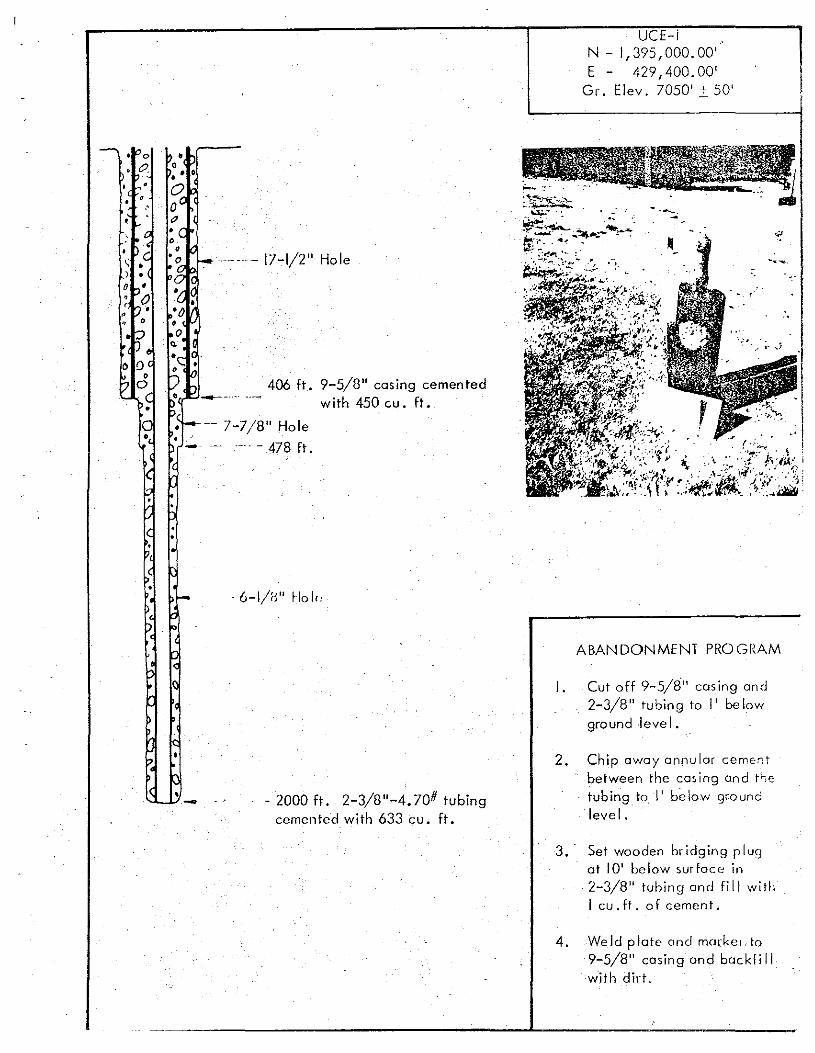
~.~~.~- 17-1/2" Hole
406 ft. 9-5/8" casing cementedwith 450 cu. ft.
• -- 7-7/8" Hole
-- -~ .-'. - 478 ft.
UCE-iN - 1,395, 000.00'E - 429,400. 00'
Gr. Elev. 7050' 2: 50'
ABANDONMENT PROGRAM
I. Cut off 9-5/8" cas ing and2-3/8" tubing to I' be lowgroundlevei.
•- - 2000 ft. 2-3/8"-4.70# tubingcemented with 633 cu. ft.
2. Chip away annular cementbetween the casing and t>-,etubing to I' below groundlevel.
3.' Set wooden bridging plugat 10' belaw surface in2-3/8" tuloing and fill withI cu. ft. af cement.
4. Weld plate and rncrk er.fo9-5/8" casing and backfi IIwith dirt.
I. Rad-S.afemonitol ing I er.rJi!, .1 .on this hole.
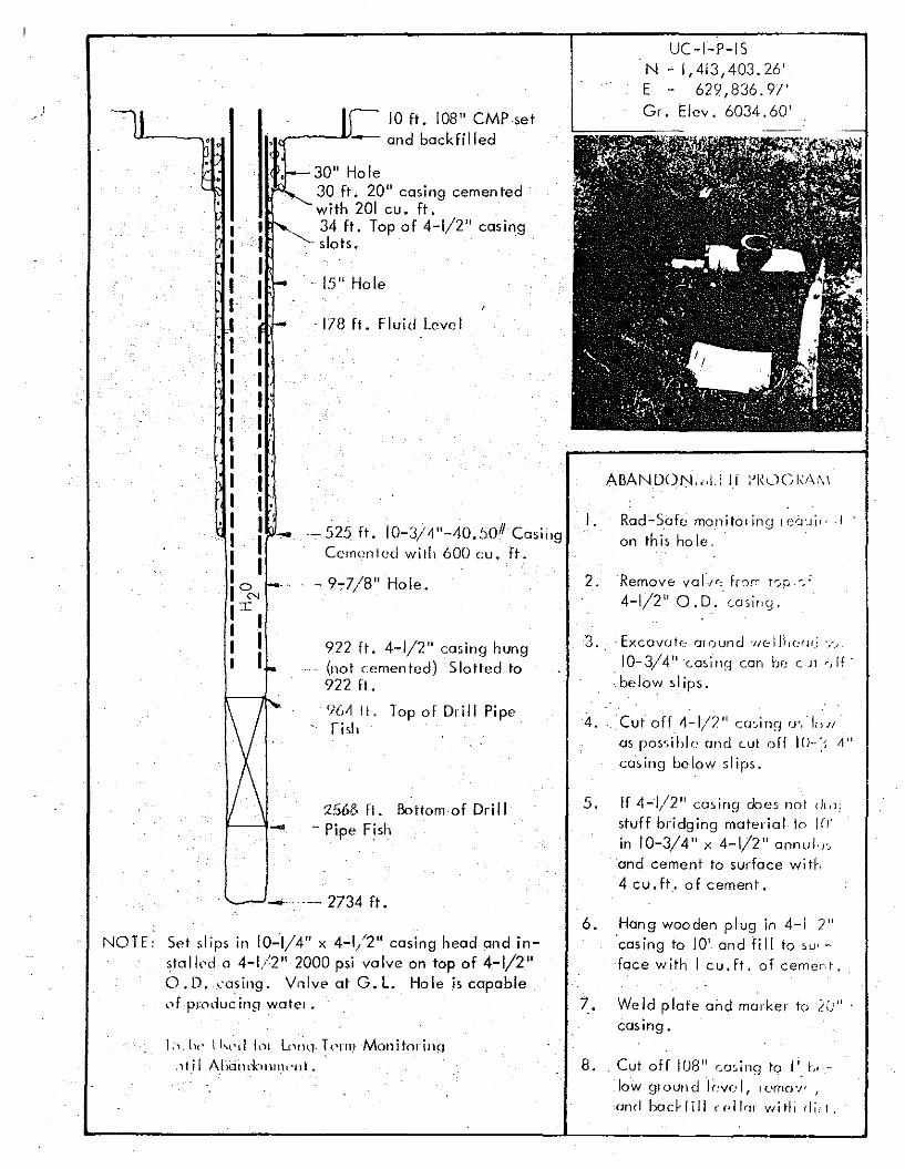
2. "Remove var.I""; fr')r; i-:..r.- j
4-1/2" O. D.' casing.
UC-I-P-ISN "1,413,403.26'E 629,836.97'Gr. Elev . 6034.60'
4. Cut off 4-1/2" cminn 0'. inN
as possi hlo (md cui off I()-:' ~"
cos inq below slips.
"3 .. Excovot« or o und "J/c:1H,(:(J(j '..-~
IO-3/41'c-o~i-nr1 can be C-Jt rJff·
'below slips.
5. If 4-1/2" casing docs no t ,1t.1:stuff bridging material to I(J'
in 10-3/4" x 4-1/2" annul.".and cement to surface with4 cu. ft. of cement.
2S68 ft. Bottom of Dri II- Pipe Fish
·178 ft. Fluid Level
·-525 ft. 10-3/~"-40.~)OIICasingCemented wilh 600 cu. ft.
'. 15" Hole
922 ft. 4-1/2" casing hung...- (not cemented) Slotted to
922 ft.
'J(,~ II. Top of Drill Pipefish
·--9.,.7/8" Hole.
_., ._- 2734 ft.
10 ft. 108" CMPset.,..-__--V_ and backfilled
30" Hole30 ft. 20" casing cemen tedwith 201 cu. ft.34 ft. Top of 4-1/2" casing
"'- slots.
I1I .I .1.I .II .I 'I-I
I1III'JI1I
NOTE: Set slips in 10-1/4" x 4-1/2" casing head and insto llod 04-1/2" 2000 psi valve on top of 4-1/2"O. D. cos inq . Vnlve at G. L. Hole is capableof produc ino wo ter •
1;,_ [)t' ll"l'1.1IcH L()!;q. Tr'nnMonitorillfl.it i l AIXJlld0111llt'lIl.
6. Hang wooden plug in 4-1 2"'casing to 10' and fill to su'
face with I c u.Ft , of cernert .
7. We Id p late and rnorker to LV' .casing.
8.. Cut off 108" co,ing to I'. ~>,low qrocn d levc·l, rc-mov- J
(mel bac!·fill ((·11,,, wi th eli, I.
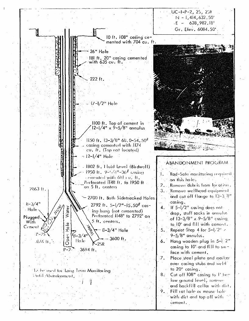
UC-I-P-2, 25, 2',1<f'! - 1,414,632.50'
. E - 628, 982 . 18'Gr.E le~. 6084.50'
I ....~---.., 10 ft. 108" casing cemented with 704 cu. ft.
1" ht'U~,'d tPI l~il~l Tc-rm MOil ito I ing;illtil ..\hlindollrnelll,
AeANDOI'-lMEt'-lT PROGRAM
I.
'casing.4. 'If 5-1/2" cos inq doe' not
drop, stuff socks in cnnulu-.
of 13-3/8" x 9-5/8" c osinqto 10' and fill with cerne«t .
Repeat Step 4 for 5-1/2" ,<
9-5/8" annulus. ,Hong wooden. plug in 5-1 2"casing 'to 10' and fi II to sur - ,
face with cement.Placesleel plate and "Wikerover casing stubs and v",ld'to 20" casing.Cut off 108" casing I" I' k',I~w glo"und l ovo l , r omovr-
end backfill cellar witl, rlill.Fill '01 hole 01 mouse 1'01.'
·wilh d ir t ancl top off wit\;
5 .
8.
7.
9.
6.
'Rad'~Sak monitor inq' I ('(ll);' (,(j
on th'i, ho I",. 2 .. Rcmov{~-'dehli" [rom 1~)(o1jrlI1 .
. 3.. "Remove wellhead "quil>l""'"'and cuI off Flouqe to 1:)<, fl"
tl'
a(i.-{~L';0L::;;~·~";--:'
1100 ft. Top of cement in,12-1/4" x 9-5/8" annulus
"I
'- 2700 ft. Both Sidetracked Holes
2792 ft. :i-1/2"-15.50# casinn hung (1I0t cerrien ted)Pp~forated 1148' to 2792' on.5 ft. centers,
1150 ft. 13-3/8" 68.0-:;4.5011
casing cornentorl with 1171icu. ft. (Top 1I0t I""alpd)
.. 12-1/4" Hole
. 8-3/4" Hole
--- 3600 fl.-2SR
, 3694 fl.
.. 17-1/2" Hole
'-''- 222 ft .
1'Io1r--- 26" Ho Ie
181 ft. 20" casing cementedwith 635 cu. ft.
1802 ft. Iluid Level IBildwcll)",. 1950 fl. 9-',,/'1"_](,11 ",,,ill!!
" , /'~tIl'llte~d willI ()HI ( H. fl.r"rlolOledH48 fl. 10 1950 ft
....--all .5 fl. c"ntr" s
'"
c
"o,
O['-2'
/B6J fl. Iis-J/4 ", Hole
cement.
L ------'---------L----...---
.."
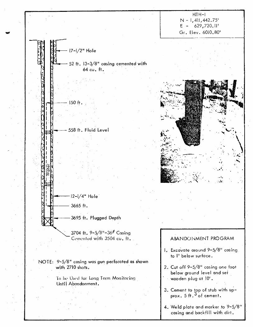
HTH-IN - 1,411,442.75'E - 629,720.11'Gr. Elev. 6010.80'
50ft.
7-1/2" Hole
12-1/4" Ha Ie'
3665 ft.
.,
..• It
".k
",'~.~
, '"",";
.. ~ '\_..1-- .
" .. ,," .
"
,
• .j: .\: ••:".r
"
"
:... ;''''i:'•• .;,'.'.-~.~'
3695 ft. PIugged Depth
58 ft. Fluid Level
52 f.t. 13-3/8" casing cemented with64 cu. ft.
-. -· I••
•
• •
•
•1- ---- IIII1
'r __-5
I111
, IIt
~I,IE1 ,1II1·
...~
3704 ft. 9-5/8"-36# CasingCe-mented with 3504 cu. ft. ABANOOI"MENT PROGRAM
I. Excavate around 9-5/8" cos inqto I' below surfoce.
NOTE: 9-5/8" casing was gun perforated as shownwith 2710 shots.
To Ill' U,,'d for l.onR Term ManitadnnUnti! Abandonment.
2. Cut off 9-5/8" casing one footbelow ground level and setwooden plug ot 10'.
3. Cement to top of stub with opprox , 5 ft. 3 of cement.
4. Weld plate and marker to 9-5/8"casing and backfill with dirt.
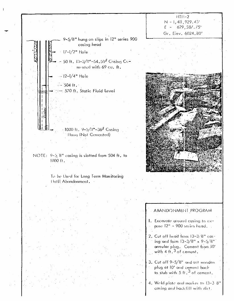
9-5/8" hung on slips in 12" series 900casing head
17-1/2" Hole
- - 50 ft. 1:;-J!B"-54.!)OII Cnsinr] Cr"nu-nlcd with 69 cu. ft.
HTH-2I" -1,411,929.43'E - 629,587.75'
Gr. Elev. 6024.80''-----------.--------1
NOTE: 9-:'."8" casing is slotted from 504 ft. toWOO fl.
f-
,-[ -III
!~15III . -
- 12-1/4" Hole
- 504 ft ..
- 570 ft. Static Fluid Level
. 1000 fl. 9-:)/:;"~3611 Cminr;lhn rq (No! C"mellted)
T,) be Use-d for Long Term Man itoringllnti I Abondonment ,
AflANDONMEIH PROGRAM
I. Excavate' cro uncl COSill9 to ex
pose' 12" - 900 "" if'S hcod .
2. Cui off head from 13-3/8" casing and form 13-3/8" x 9-5/8'"annular plug. Cement from .10'with 4ft. 3 of cement. .
3. Cut off 9-5/8" and -sc t woodenplug at 10' end cement bad·to stuh wi th 5 fl. 3 of cemen t •
4. Wl'ld p loto ulld rna",·, to IJ-J 8"cns inq und bcck Iill with ditto
APPENDIX E
HOLES ASSIGNED TO THE BUREAU
OF LAND MANAGEMENT

This page intentionally left blank
The following holes will be assigned to the United States Bureau of land
Management:
Hole Number Locale
UCE-2 Wi 1I0w Creek
UCE-16 tvIonitor Valley
UCE-17 Hot Creek Valley
HTH-4 Little Smokey
HTH-23 Hot Creek Valley
-
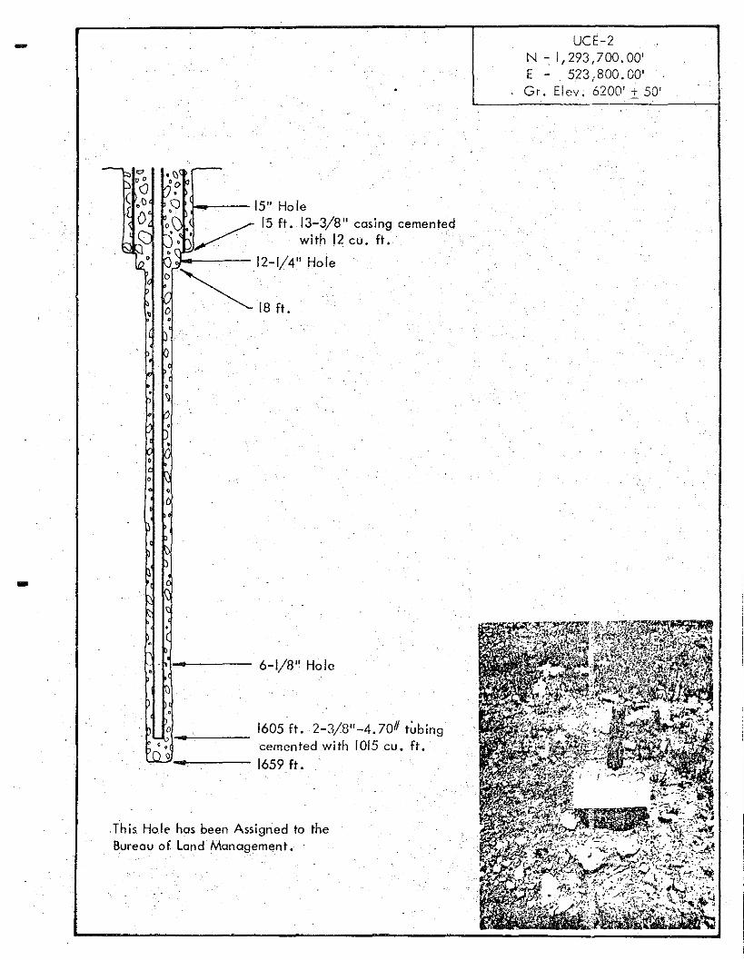
• <:Ie'0
~6 15" Hole,'r,- /5 ft. 13-3/8" casing cemented~; .~ with 12 cu. ft.
~~ 12-1/4" HoleIV "'- .
D ...~ 18ft.o•
UCE-2N - 1,293,l00.00'E': 523/800.00'Gr. Elev. 6200' i. 50'
---':_--:-j
....
•c ,
.This Hole has been Assigned to theBureau of. Land Management.
-
o'":"'\_w-----••Po Q -.
6-1/8" Hole
1605 ft. 2-3/8"-4.70# tubingcemented with 1015 cu. ft.1659 ft.
Lhis Hoi" hosbeen Assign~d to til<' .R\.q C\111 o l Ll.1lld MOIl09.('ltlPllt.
lID
(J ."..
-
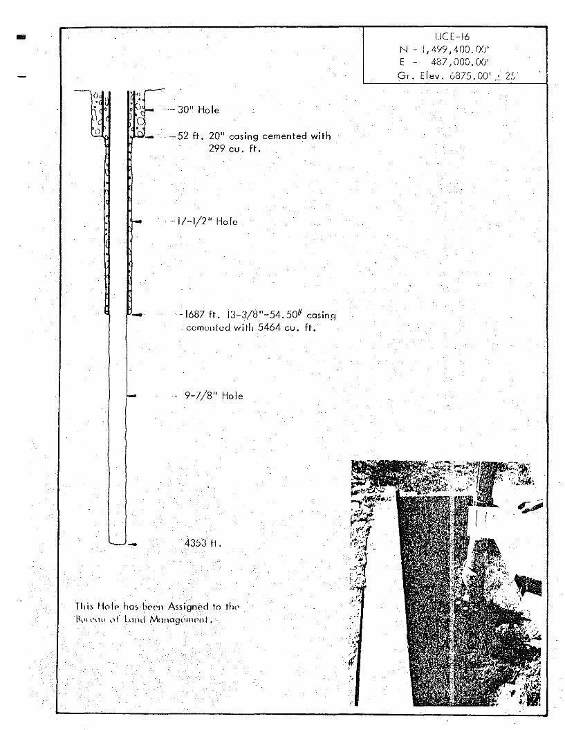
. ._-- 30" Hole
20" casing cemented with299 cu , ft,
. -17~1/2" Hole
-1687 Ft , 13-3/8"-54,5011 cosinecemented with 5464 CU, Ft;.
-- 9-7/8" Hole
4353 H,
LJCE-16N - 1,499,400. OU'E - 437, 000. 00'Gr. Elev. 6875.00' 2:;
,-"
l\----OC 30" Hole
or-o-I-- --- 34 ft. 20" casing cemented with207 cu. ft.
f.:. - 17-1/2" Hole
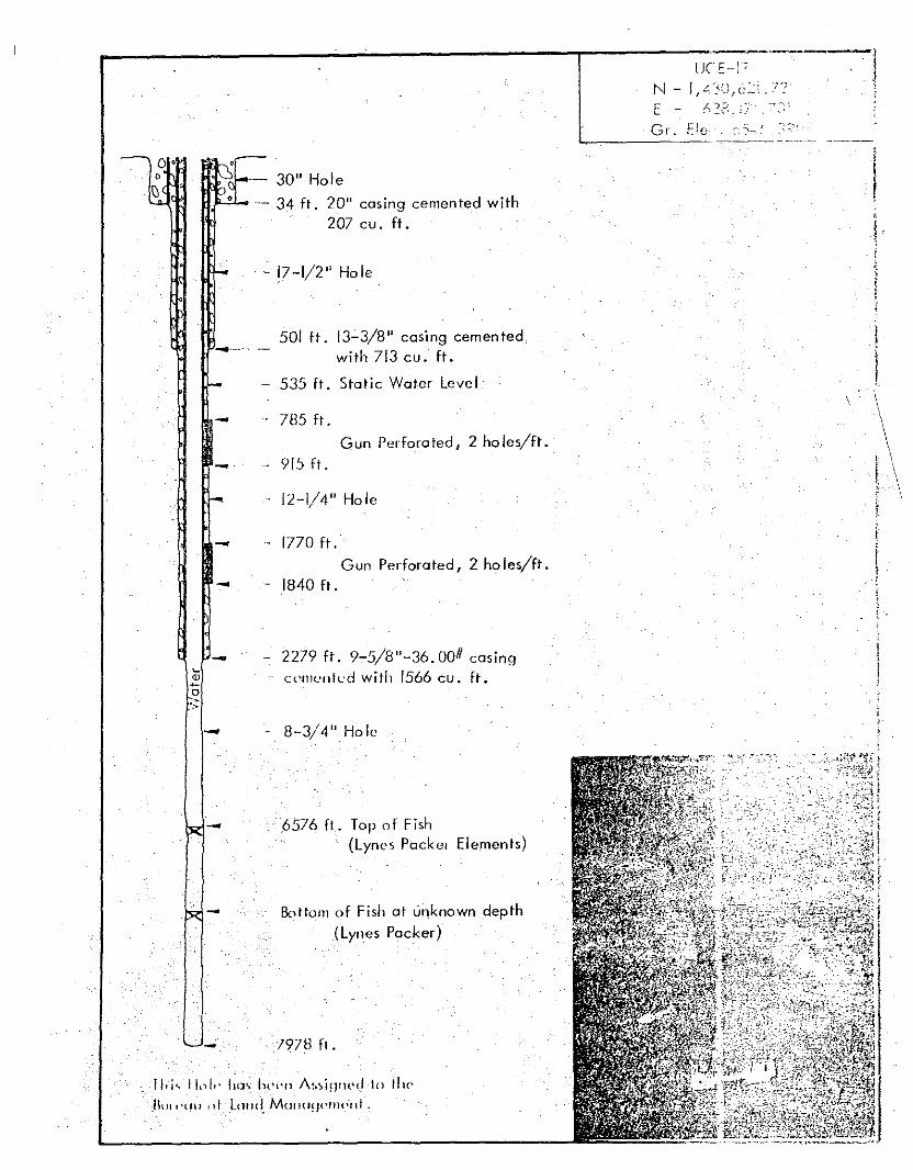
L1Cc--:; .----!N -lfL._<},6~\.7?' {E - A?P j~.:' ----;~
Gr. Ele :C'--L...---~--.~~----- -- ---
.-t.-...501 ft. 13-3/8" casing cemented
with 713 cu. ft.
I- - 535 ft. Static Water Level\
.. - 785 ft. \Gun Perforated, 2 1,0 les/ft. \-- - 915 ft. \
r- - 12-1/4" Hole \
- - 1770 ft.• Gun Perforated, 2 1,0 les/ft.- - 1840 ft.
-- - 8-3/4" Hole
I "1... 11\)/" hov Iu-r-u 1\~I~i!-l'H'{.f 10 til('
Btll l'tHI, Lnlld, M(JII<ln('f1H'-tll~
-
~-
- 2279 ft. 9-5/8"-36. 0011 casingCC'II1L'IliL'd with 1566 cu. ft.
6576 ft .. Top of Fish(Lynes Packer Elements)
Bo t tom of Fish at unknown depth(Lynes Packer)
/978 ft.
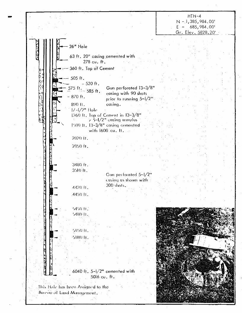
.. HTH-4N -1,385,984.00'E - 685,984,00'Gr. Elev . 5828.20'
" ...>-- 26" Hole
Gun perforated 13-3/8"casing with 90 shotsprior to running 5-1/2"casing.
7070 If.
LO~;() fl.
8'JO II .1/-1/7" 1101"1760 II. lop or Cornc-n I in 13-3/8"
i' ')_1/2" cos inq fJlH1UIU5
I',00 It. 1:3-3/8" <:minq cumouj odwilh 1600 cu. It.
63 ft. 20" casing cemented with--- 278 cu. ft .
• - ,-- 360 ft. Top of Cement
c--- 505 ft.
- 520 ft.--- 575 ft.- -- 585 ft.
- 810 It.
-
., I,,I
1"i, 11,,1 t ' hm 1"'('11 /\ssiqlH'd 10 theBUI ('\HI lH LUlldMwHJHPlIH.'nl.
- :WJ(J II.- 3~JI () It.Gun pel lora ted 5-1/2"(.(J~inq (J~_shown with
~~7() It . 300 ,.1"""
- ~~~,() It.
- 'd',o I I,- 'J~110 It.
6040 It. 5-1/2" cemented with5016 cu. ft.-
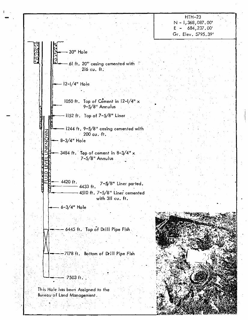
HTH-23N - I, 368,087. 00'E - 684,237.00'Gr. Elev, 5795.39'
•
Top of cement in 8-3/4" x7-5/8" Annulus .
•
Bottom of OrirJ Pipe Fish
4433 ft. 7-5/8" Liner pa~ted.
4510 ft. 7-5/8" Liner cementedwith 311 cu. ft.
Top of C;ment in 12-1/4" X
9-5/8" Annulus
Top of 7-5/8"Liner .
Hole
• 20"· casing cemented with 216 cu. ft ,
Hole
Hole
ft. Top;f Drill Pipe Fish
r, 9-5/8" casing cemented with200 cu. ft.
Hole
5 ft •..
Th is Holehos been Assigned to theBureau of Land Management.
~00 -G~ 30"•
~.'
---- 61 ft
~ 12-1/4"
1050 ft~-
rJ52 ft
Z ·-1244f~ .
I~ i- 8-3/4"~
I~ "-- 3484 ft .:.....JUJ
>UJ.....J
a::J
~ \-- 4420 ft.
•
l....- 6-3/4"
6445•
I·
7178 ft•
7 03•