Embed Size (px)
Citation preview
OILFIELD MANUAL
BWS P/N:40950794 REV: 0
SEPTEMBER 2015

OILFIELD MANUAL CONTENTSINTRODUCTION 4
Products 4
BWS COMPANY HISTORY 5Quality Policy 6
COMPLIANCE PLATE 7SAFETY PRECAUTIONS 8
1.1 Operating Safety 91.2 Maintenance Safety 91.3 Loading Safety 91.4 Safety Decal Maintenance 91.5 Sign-off Form 10
SAFETY DECALS 112.0 Safety Decals 11
OPERATING PROCEDURES 133.1 Break-in/Inspection 133.1.1 500 mile / 800km Inspection 133.1.2 10,000 mile / 16,000 km Inspection 133.1.3 20,000 mile / 32,000 km Inspection 133.2 Pre-operation Vehicle Inspection Procedure 14
WALK AROUND SEQUENCE 143.4 Fifth Wheel Operating Instructions (Figure 3) 17
3.4.1 Coupling Procedure 173.4.2 Uncoupling Procedure 18
3.5 Loading 183.5.1 Trailer Weight Distribution 193.5.2 Load Restraints 20
3.6 Transporting 213.6.1 Braking Guidelines 213.6.2 Tires 22
SCISSORNECK OPERATION 29HYDRAULIC GOOSENECK 30
HDG LH 30
MAINTENANCE AND INSPECTION 36HUB ALERT™ 38
4.1 KingPin and Upper Coupler 394.2 Axles 39
4.2.1 Suggested Preventative Maintenance Schedule 394.2.2 Axle Alignment 39
4.3 Wheels 424.3.1 Wheel Hubs 424.4.1 Bearing Adjustment Procedure 444.4.2 Bearing Adjustment 45
4.5 Grease Retainers / Oil Seals 464.5.1 Ring and Seal Type (Oil) Maintenance 464.5.2 Ring and Seal Type (Oil) Replacement 46
4.6 Suspension System (Air) 474.6.1 Inspection 47
4.7 Suspension System 474.7.1 Mechanical Suspension 484.7.2 Suspension System 484.7.3 Radius Rods 494.7.4 Rocker Bushings and Hangers 49
4.8 Air-Ride Suspension (Figure 49) 504.8.1 Maintenance 514.8.2 Pivot Connection 524.8.3 Air Control System 524.8.4 Height Control Valve 524.8.5 Height Control Valve with Dual Ride Height 524.8.6 Air Dump Valve 53
4.9 Brakes 544.9.1 Preventative Maintenance 544.9.2 Maintenance 56
4.10 Torque Specifications 574.11 Tires 57
4.11.1 Tire Care and Maintenance 574.11.2 Tire Inspection 574.11.3 Mechanical Irregularities 584.11.4 Radial Tire Application 584.11.5 Matching Tires to Rims 584.11.6 Tire Wear Patterns Over-Inflation: 58
4.12 Air System Components 594.12.1 Glad Hands 594.12.2 ABS 604.13.1 SUSPENSION DUMP CONTROL (RA014GL): 654.13.2 SUSPENSION CONTROL (RA019SA-B150): 664.13.3 SUSPENSION TAILGATE CONTROL (RA011A-DG3): 674.13.3 SUSPENSION DUMP/TAILGATE CONTROL (RA011A-DG2): 684.13.4 STEERABLE LIFT SUSPENSION CONTROL (RA016SSA-25): 694.13.5 SUSPENSION CONTROL (RA016SRA-3280) 704.13.6 SUSPENSION DUMP/TAILGATE CONTROL (RA011A-DG) 71
4.14 Electrical System 72
TROUBLE SHOOTING 82WARRANTY 86
Structural & Component Warranties 86BWS Contact Information 86
4OILFIELD MANUAL
INTRODUCTION
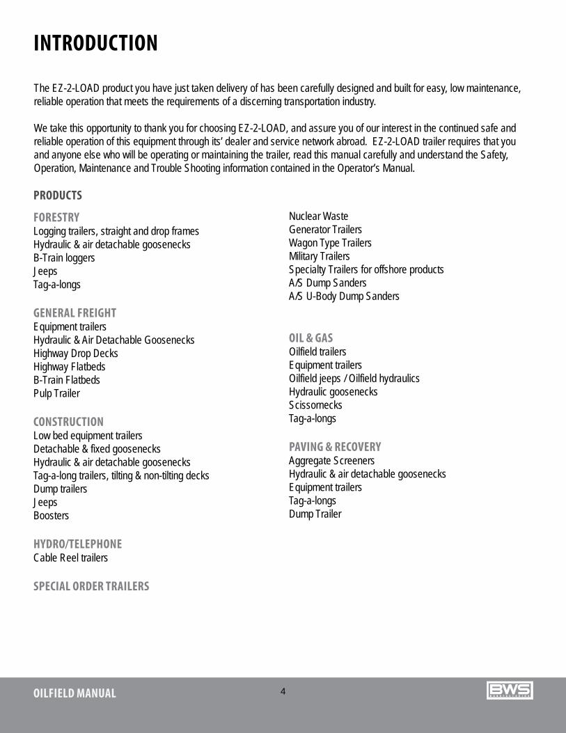
FORESTRYLogging trailers, straight and drop framesHydraulic & air detachable goosenecksB-Train loggersJeepsTag-a-longs
GENERAL FREIGHTEquipment trailersHydraulic & Air Detachable GoosenecksHighway Drop DecksHighway FlatbedsB-Train FlatbedsPulp Trailer
CONSTRUCTIONLow bed equipment trailersDetachable & fixed goosenecksHydraulic & air detachable goosenecksTag-a-long trailers, tilting & non-tilting decksDump trailersJeepsBoosters
HYDRO/TELEPHONECable Reel trailers
SPECIAL ORDER TRAILERS
Nuclear WasteGenerator TrailersWagon Type TrailersMilitary TrailersSpecialty Trailers for offshore productsA/S Dump SandersA/S U-Body Dump Sanders
OIL & GASOilfield trailersEquipment trailersOilfield jeeps / Oilfield hydraulicsHydraulic goosenecksScissornecksTag-a-longs
PAVING & RECOVERYAggregate ScreenersHydraulic & air detachable goosenecksEquipment trailersTag-a-longsDump Trailer
PRODUCTS
The EZ-2-LOAD product you have just taken delivery of has been carefully designed and built for easy, low maintenance, reliable operation that meets the requirements of a discerning transportation industry.
We take this opportunity to thank you for choosing EZ-2-LOAD, and assure you of our interest in the continued safe and reliable operation of this equipment through its’ dealer and service network abroad. EZ-2-LOAD trailer requires that you and anyone else who will be operating or maintaining the trailer, read this manual carefully and understand the Safety, Operation, Maintenance and Trouble Shooting information contained in the Operator’s Manual.
5OILFIELD MANUAL
BWS COMPANY HISTORY
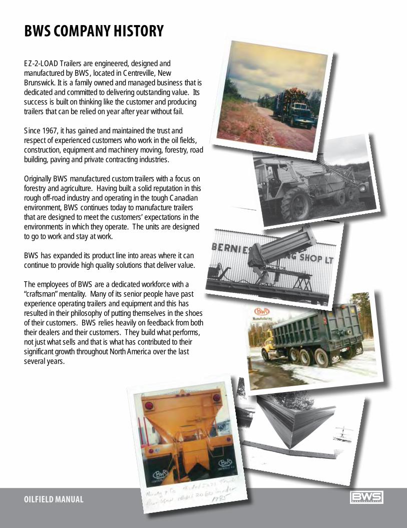
EZ-2-LOAD Trailers are engineered, designed and manufactured by BWS, located in Centreville, New Brunswick. It is a family owned and managed business that is dedicated and committed to delivering outstanding value. Its success is built on thinking like the customer and producing trailers that can be relied on year after year without fail.
Since 1967, it has gained and maintained the trust and respect of experienced customers who work in the oil fields, construction, equipment and machinery moving, forestry, road building, paving and private contracting industries.
Originally BWS manufactured custom trailers with a focus on forestry and agriculture. Having built a solid reputation in this rough off-road industry and operating in the tough Canadian environment, BWS continues today to manufacture trailers that are designed to meet the customers’ expectations in the environments in which they operate. The units are designed to go to work and stay at work.
BWS has expanded its product line into areas where it can continue to provide high quality solutions that deliver value.
The employees of BWS are a dedicated workforce with a “craftsman” mentality. Many of its senior people have past experience operating trailers and equipment and this has resulted in their philosophy of putting themselves in the shoes of their customers. BWS relies heavily on feedback from both their dealers and their customers. They build what performs, not just what sells and that is what has contributed to their significant growth throughout North America over the last several years.
6OILFIELD MANUAL
BWS Manufacturing is totally committed to understanding and meeting the quality needs and expectations of all our customers. Our company has a proud reputation for delivering quality equipment and components.
BWS strives for continuous improvement of our product and meeting the objectives of the company. We are also committed to the continuous improvement of our quality management system to insure its suitability to meet all company, customer, regulatory, legal and ISO requirements.
The entire BWS team will adhere to the spirit and intent of our quality policy, as well as the directives of this quality assurance manual and its supporting quality system documentation. We will continue to aggressively strive to insure that customer satisfaction is achieved at all times, and in all things.
QUALITY POLICY
QA-DOC-004-VER-001
7OILFIELD MANUAL
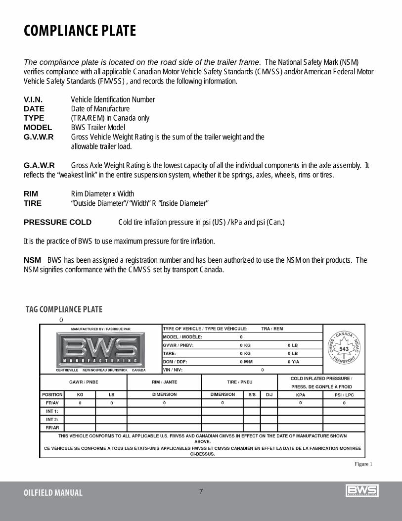
The compliance plate is located on the road side of the trailer frame. The National Safety Mark (NSM) verifies compliance with all applicable Canadian Motor Vehicle Safety Standards (CMVSS) and/or American Federal Motor Vehicle Safety Standards (FMVSS) , and records the following information.
V.I.N. Vehicle Identification Number DATE Date of ManufactureTYPE (TRA/REM) in Canada onlyMODEL BWS Trailer ModelG.V.W.R Gross Vehicle Weight Rating is the sum of the trailer weight and the allowable trailer load.
G.A.W.R Gross Axle Weight Rating is the lowest capacity of all the individual components in the axle assembly. It reflects the “weakest link” in the entire suspension system, whether it be springs, axles, wheels, rims or tires.
RIM Rim Diameter x WidthTIRE “Outside Diameter”/ “Width” R “Inside Diameter”
PRESSURE COLD Cold tire inflation pressure in psi (US) / kPa and psi (Can.) It is the practice of BWS to use maximum pressure for tire inflation.
NSM BWS has been assigned a registration number and has been authorized to use the NSM on their products. The NSM signifies conformance with the CMVSS set by transport Canada.
TAG COMPLIANCE PLATE
COMPLIANCE PLATE
Figure 1
8OILFIELD MANUAL
SAFETY PRECAUTIONS
SAFETY ALERT SYMBOL
WARNING and CAUTION with the safety message. The appropriate signal word for each message has been selected using the following guidelines:
DANGER - An immediate specific hazard which WILL result in severe personal injury or death if the proper precautions are not taken.
WARNING - A specific hazard or unsafe practice which COULD result in severe personal injury or death if proper precautions are NOT TAKEN.
CAUTION - Unsafe practices which COULD result in personal injury if proper precautions are NOT TAKEN, or as a reminder of good safety practices.
YOU are responsible for the SAFE operation and maintenance of your
This safety Alert symbol means ATTENTION! BECOME ALERT! YOUR SAFETY IS INVOLVED!
The Safety Alert Symbol identifies important safety messages on the BWS trailer and in the manual. When you see the symbol, be alert to the possibility of personal injury or death. Follow the instructions in the safety message.
EZ-2-LOAD trailer. YOU must ensure that you and anyone else who is going to operate, maintain or work around the trailer be familiar with the operating and maintenance procedures and related SAFETY information contained in the operator’s manual.
Remember, YOU are the key to safety. Good safety practices not only protect you but also the people around you. Make these practices a working part of your safety program. Be certain that EVERYONE operating this equipment is familiar with the recommended procedures and follows all safety precautions. Do not risk injury or death.
Remember the difference between being a driver and an efficient operator: Drivers may drive but an operator is a very safe, cost efficient and professional person.
Trailer owners must review operating instructions with operators or employees before allowing them to operate the equipment, and review at least annually thereafter.
The most important device on this equipment is a SAFE operator. It is the operator’s responsibility to read and understand ALL safety and operating instructions in the manual and to follow them.
Any person who has not read and understood all operating and safety instructions is not qualified to operate the equipment.
Do not modify the equipment in any way. Unauthorized modification may impair the function and/or safety of the equipment and affect trailer life.
THINK SAFETY! WORK SAFELY!
9OILFIELD MANUAL
1.1 OPERATING SAFETY1. Read and understand the operator’s manual and all safety signs before operating, maintaining or adjusting the EZ-2-
LOAD trailer.2. Do not allow riders on any part of the trailer during road or highway travel.3. Keep hands, feet, clothing and hair away from all moving parts.4. Tie load before moving or transporting trailer.5. Check tie-downs frequently during transport to prevent shifting or movement of the cargo.6. Clear the area of all bystanders, especially children, before starting up and operating the truck, trailer or equipment.7. Make sure that all lights and reflectors required by local highways and transport authorities are in place, clean and can
be seen clearly by all overtaking and oncoming traffic.8. Before disconnecting the tractor from the trailer unit(s) make sure that the tractor and trailer are on level ground and
that the trailer park brakes are applied.
1.4 SAFETY DECAL MAINTENANCE1. Keep safety decals and signs clean and legible at all times.2. Replace safety decals and signs that are missing or have become illegible.3. When ordering replacement parts that display a safety sign or decal, be sure to order the replacement safety sign or
decal also.4. Safety decals or signs are available from your Dealer Parts Department.
1.2 MAINTENANCE SAFETY1. Read and understand all the information in the operator’s manual regarding maintenance, adjustment and operation of
any EZ-2-LOAD trailer or unit.2. Stop the engine, remove ignition key and set the park brake before adjusting, servicing or maintaining any part of the
trailer unit.
1.3 LOADING SAFETY1. Do not drop load on trailer in order to prevent damaging the cargo or the trailer.2. Place concentrated heavy loads over structural beams when loading.3. Tie load securely before moving or transporting.4. Check tie-downs frequently when transporting and keep them tight.5. Do not exceed load concentration and total load carrying specifications for trailer.6. Install lights or flags on load if it extends beyond deck.7. Do not side load.
10OILFIELD MANUAL
1.5 SIGN-OFF FORMAnyone operating and/or maintaining an EZ-2-LOAD ADG trailer must read and clearly understand ALL safety, operating and maintenance information presented in this manual.
Do not operate or allow anyone else to operate this equipment until such information has been reviewed. Review this information annually.
Make these periodic reviews of SAFETY and OPERATION a standard practice for all of your equipment.
A sign-off sheet is provided for your record keeping to show that all personnel who will be operating or maintaining the equipment have read, and understood, the information in the operator’s manual and have been instructed in the operation of the equipment.
DATE EMPLOYEE NAME EMPLOYEE SIGNATURE
11OILFIELD MANUAL
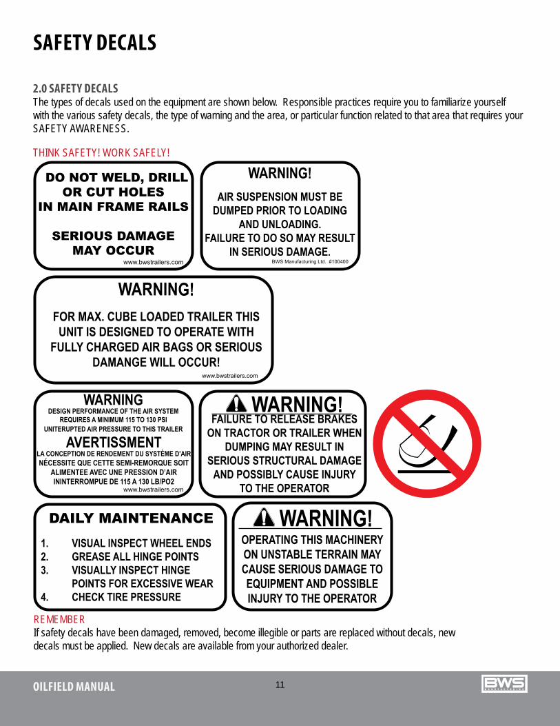
2.0 SAFETY DECALSThe types of decals used on the equipment are shown below. Responsible practices require you to familiarize yourself with the various safety decals, the type of warning and the area, or particular function related to that area that requires your SAFETY AWARENESS.
THINK SAFETY! WORK SAFELY!
SAFETY DECALS
REMEMBER If safety decals have been damaged, removed, become illegible or parts are replaced without decals, new decals must be applied. New decals are available from your authorized dealer.
12OILFIELD MANUAL
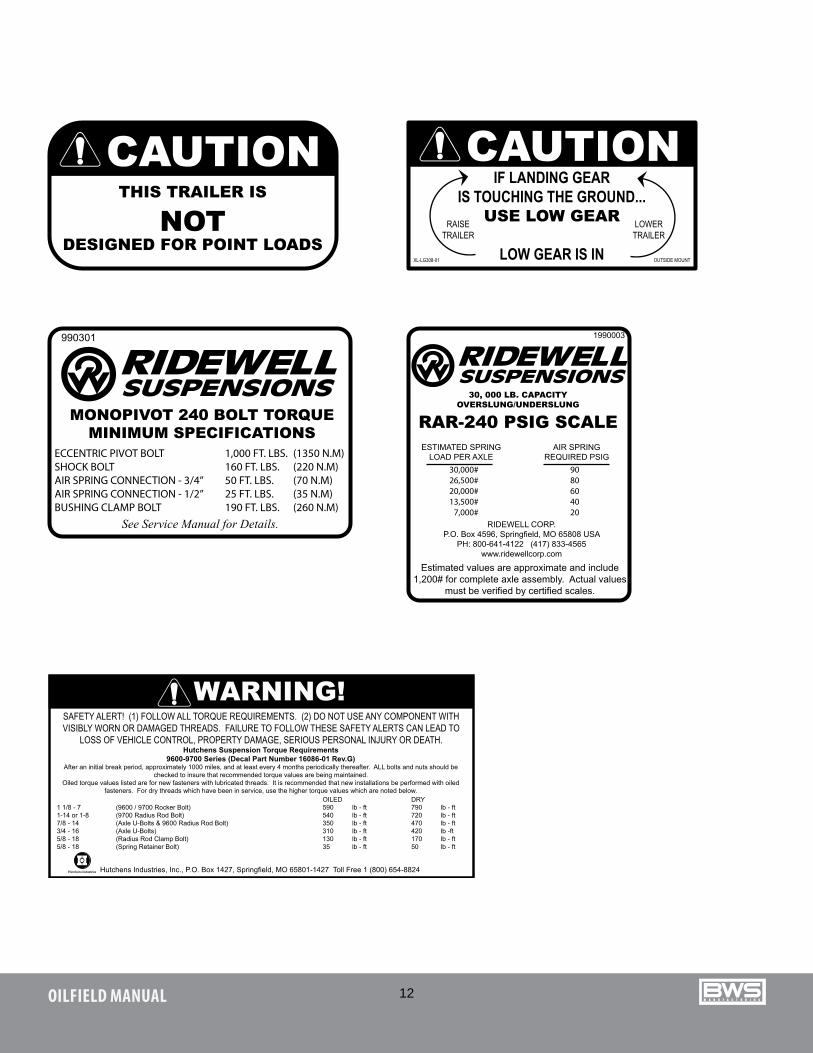
SAFETY ALERT! (1) FOLLOW ALL TORQUE REQUIREMENTS. (2) DO NOT USE ANY COMPONENT WITH VISIBLY WORN OR DAMAGED THREADS. FAILURE TO FOLLOW THESE SAFETY ALERTS CAN LEAD TO
LOSS OF VEHICLE CONTROL, PROPERTY DAMAGE, SERIOUS PERSONAL INJURY OR DEATH.
WARNING!
Hutchens Suspension Torque Requirements9600-9700 Series (Decal Part Number 16086-01 Rev.G)
After an initial break period, approximately 1000 miles, and at least every 4 months periodically thereafter. ALL bolts and nuts should be checked to insure that recommended torque values are being maintained.
Oiled torque values listed are for new fasteners with lubricated threads. It is recommended that new installations be performed with oiled fasteners. For dry threads which have been in service, use the higher torque values which are noted below.
Hutchens Industries, Inc., P.O. Box 1427, Springfield, MO 65801-1427 Toll Free 1 (800) 654-8824
OILED DRY1 1/8 - 7 (9600 / 9700 Rocker Bolt) 590 lb - ft 790 lb - ft1-14 or 1-8 (9700 Radius Rod Bolt) 540 lb - ft 720 lb - ft7/8 - 14 (Axle U-Bolts & 9600 Radius Rod Bolt) 350 lb - ft 470 lb - ft3/4 - 16 (Axle U-Bolts) 310 lb - ft 420 lb -ft5/8 - 18 (Radius Rod Clamp Bolt) 130 lb - ft 170 lb - ft5/8 - 18 (Spring Retainer Bolt) 35 lb - ft 50 lb - ft
13OILFIELD MANUAL
OPERATING PROCEDURES
3.1.1 500 MILE / 800KM INSPECTION After the first 500 miles/800km of service, some “settling in” will have occurred, particularly in the suspension components.
AT THIS TIME:1. Re-torque all bolts and fasteners paying particular attention to the axle U-bolts, hub studs, upper and lower fifth wheel
bolts and the suspension system. Refer to values in the maintenance section when re-torquing.2. Check tires for proper inflation pressures and rim alignment. Re-torque wheel nuts. Block the axle and spin the
wheels. Check for brake drag and wheel bearing adjustment.3. Check oil levels in hubs. Maintain proper oil level. If any levels are low, check for leaks and repair.4. Check axle alignment. Refer to maintenance section for procedure.
3.1 BREAK-IN/INSPECTION Time and distance specify the normal break-in procedure for an EZ-2-LOAD trailer:
1. Check slack adjuster function for the first 3 weeks of operation.2. Check hub oil levels daily for the first 3 weeks of operation.3. Check tires for proper inflation pressures. Re-torque wheel nuts after 100 km.
3.1.2 10,000 MILE / 16,000 KM INSPECTION1. Check the function and adjustment of the brakes on each axle. No shoes should drag on the drum when the
brakes are not applied.2. Check tire inflation pressures and tread wear. Always match tires with tread wear that is worn to 1/8” in difference.
If unusual or excessive tire wear occurs, it indicates something is wrong. Check further to determine the cause and correct it. See tires section for further information.
3. Re-torque all bolts and bolted connections.4. Visually check all welds and adjacent areas for cracks. Any cracks should be repaired as soon as possible by an
EZ-2-LOAD dealer.5. Ensure all suspension hangers and related members are tight and secure.6. Check axle alignment. Refer to maintenance section for procedure.
3.1.3 20,000 MILE / 32,000 KM INSPECTION 1. Check each brake lining for wear. Replace or adjust as required.2. Check the axle alignment. Refer to maintenance section for procedure. The operator can then go to the service
schedule as defined in the service intervals section on page 36.
14OILFIELD MANUAL
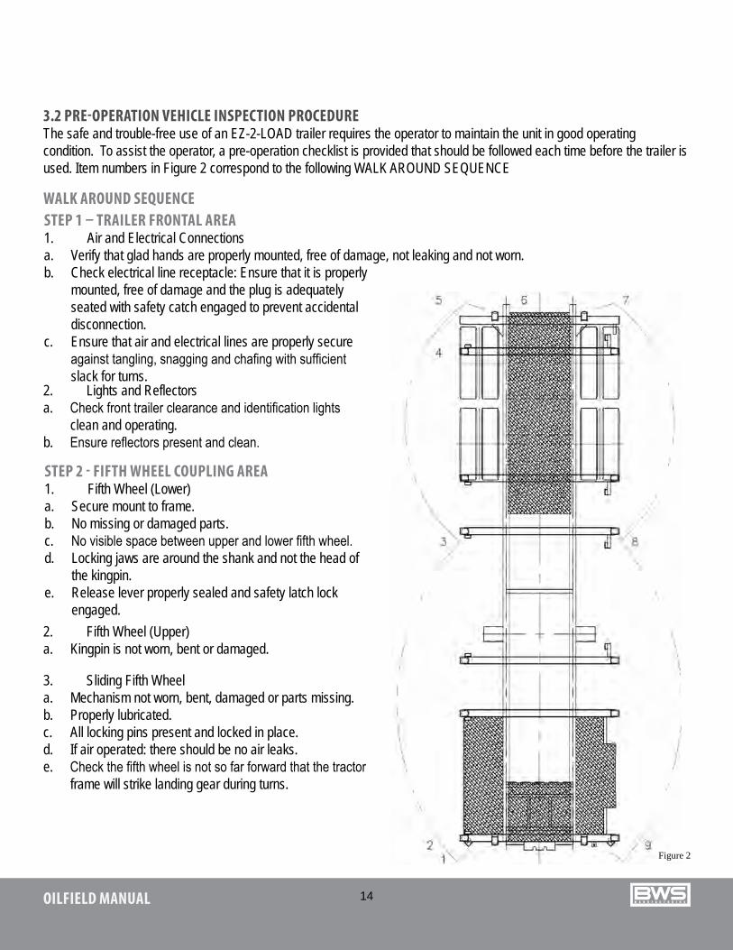
3.2 PRE-OPERATION VEHICLE INSPECTION PROCEDUREThe safe and trouble-free use of an EZ-2-LOAD trailer requires the operator to maintain the unit in good operating condition. To assist the operator, a pre-operation checklist is provided that should be followed each time before the trailer is used. Item numbers in Figure 2 correspond to the following WALK AROUND SEQUENCE
WALK AROUND SEQUENCE
Figure 2
STEP 1 – TRAILER FRONTAL AREA1. Air and Electrical Connectionsa. Verify that glad hands are properly mounted, free of damage, not leaking and not worn.b. Check electrical line receptacle: Ensure that it is properly
mounted, free of damage and the plug is adequately seated with safety catch engaged to prevent accidental disconnection.
c. Ensure that air and electrical lines are properly secure against tangling, snagging and chafing with sufficient slack for turns.
STEP 2 - FIFTH WHEEL COUPLING AREA1. Fifth Wheel (Lower)a. Secure mount to frame.b. No missing or damaged parts.c. No visible space between upper and lower fifth wheel.d. Locking jaws are around the shank and not the head of
the kingpin.e. Release lever properly sealed and safety latch lock
engaged.
2. Lights and Reflectorsa. Check front trailer clearance and identification lights
clean and operating.b. Ensure reflectors present and clean.
2. Fifth Wheel (Upper)a. Kingpin is not worn, bent or damaged.
3. Sliding Fifth Wheela. Mechanism not worn, bent, damaged or parts missing.b. Properly lubricated.c. All locking pins present and locked in place.d. If air operated: there should be no air leaks.e. Check the fifth wheel is not so far forward that the tractor
frame will strike landing gear during turns.
15OILFIELD MANUAL
STEP 6 - REAR OF TRAILER1. Lights and Reflectorsa. Rear clearance and identification lights – clean, operating and proper color.b. Reflectors are clean and proper color.c. Taillights - clean, operating and proper color.
STEP 5 - RIGHT REAR TRAILER WHEEL AREA1. Wheels/Axlesa. Check condition of wheels and rims. Verify that there are – no cracked or bent rims, broken spacers, studs, clamps or
lugs.b. Condition of tires – properly inflated, valve stems not touching wheel rims or brake drums, valve caps in place, no
serious cuts, bulges, tread wear or any signs of misalignment and no debris stuck between the tires.c. Tires all same type, e.g. DO NOT mix radial and bias types on the same axle. d. Wheel bearings and hub have no obvious leaking.e. Mud flaps in place and in good condition.f. If equipped with sliding axles check position and alignment, look for damaged, worn or missing parts. Check for
locking pins in locking position.g. Ensure that air lines are not cracked, cut, crimped or otherwise damaged and secured against tangling, snagging or
chafing.2. Suspensiona. Condition of spring(s), spring hangers, equalizers and U-bolts. b. Axle alignment.c. Condition of torque rod arms and bushings.
2. Cargo Securementa. Cargo properly loaded side to side and back to front.b. Check cargo tie-downs and ensure they are tight. National Safety Code Standard 10 Cargo Securement.c. Ensure concentrated load is positioned over structural beams.d. Canvas or tarp (if required) are properly secured to prevent water damage or blockage of either the mirrors or rear
lights.e. Check “B” train 5th wheel.
STEP 7- LEFT REAR TRAILER WHEEL AREA AND BRAKESCheck all items as done on right side (step 5).
STEP 8- LEFT SIDE OF TRAILER AREACheck all items as done on right side (step 3).
16OILFIELD MANUAL
STEP 9- TRAILER(S) FUNCTIONAL CHECK (TRACTOR ATTACHED)1. Check for proper connection of air brake glad hands, and secure contact of electrical connection.2. Start engine.3. Build up air pressure in the tractor-trailer systems.4. Turn on lights and inspect for proper function of:
a. Clearance lightsb. Identification lightsc. Turn signals and 4-way flashersd. Side marker lightse. Tail lightsf. Stop lights
5. Check the function of brakes.
i. Release trailer emergency brakes.ii. Apply service brakes.
Air loss should not exceed:3 psi per minute on single vehicles.4 psi per minute on combination.
a. Apply service brakes.b. Apply parking brakes.c. Apply accelerator with brakes in
emergency to ensure park brake functions.d. Stop engine.
17OILFIELD MANUAL
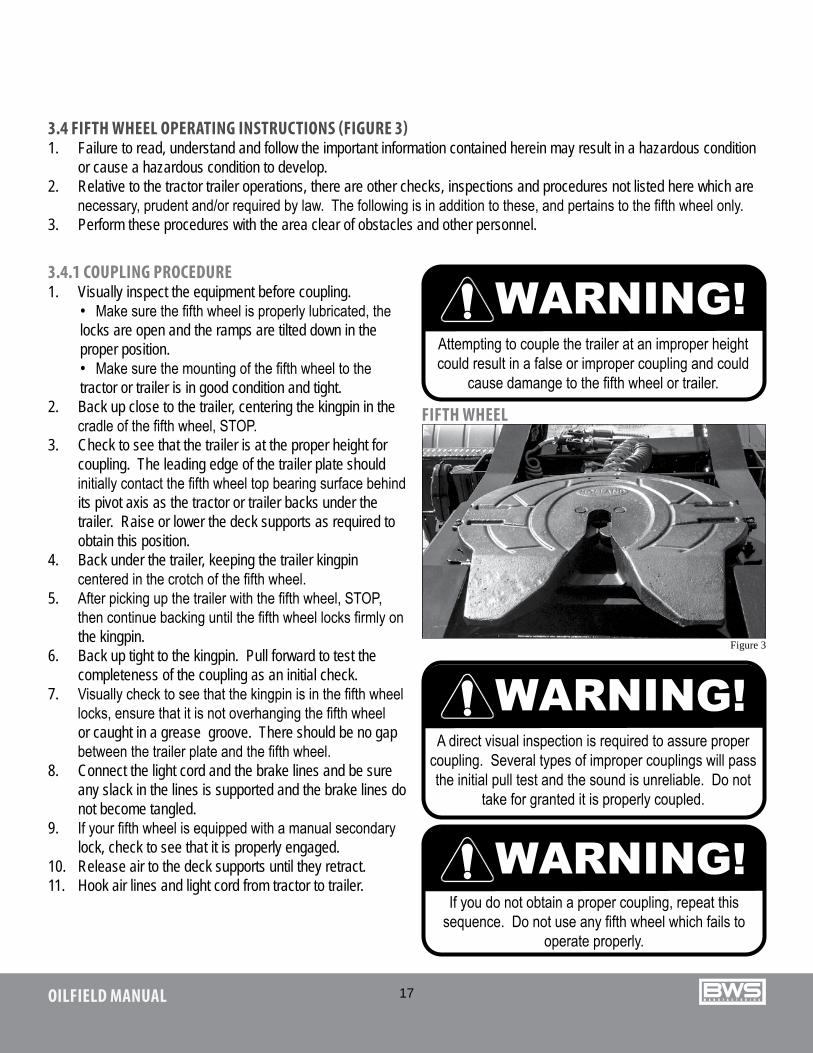
3.4 FIFTH WHEEL OPERATING INSTRUCTIONS (FIGURE 3)1. Failure to read, understand and follow the important information contained herein may result in a hazardous condition
or cause a hazardous condition to develop.2. Relative to the tractor trailer operations, there are other checks, inspections and procedures not listed here which are
necessary, prudent and/or required by law. The following is in addition to these, and pertains to the fifth wheel only.3. Perform these procedures with the area clear of obstacles and other personnel.
FIFTH WHEEL
Figure 3
3.4.1 COUPLING PROCEDURE1. Visually inspect the equipment before coupling.
• Make sure the fifth wheel is properly lubricated, the locks are open and the ramps are tilted down in the proper position.• Make sure the mounting of the fifth wheel to the tractor or trailer is in good condition and tight.
2. Back up close to the trailer, centering the kingpin in the cradle of the fifth wheel, STOP.
3. Check to see that the trailer is at the proper height for coupling. The leading edge of the trailer plate should initially contact the fifth wheel top bearing surface behind its pivot axis as the tractor or trailer backs under the trailer. Raise or lower the deck supports as required to obtain this position.
4. Back under the trailer, keeping the trailer kingpin centered in the crotch of the fifth wheel.
5. After picking up the trailer with the fifth wheel, STOP, then continue backing until the fifth wheel locks firmly on the kingpin.
6. Back up tight to the kingpin. Pull forward to test the completeness of the coupling as an initial check.
7. Visually check to see that the kingpin is in the fifth wheel locks, ensure that it is not overhanging the fifth wheel or caught in a grease groove. There should be no gap between the trailer plate and the fifth wheel.
8. Connect the light cord and the brake lines and be sure any slack in the lines is supported and the brake lines do not become tangled.
9. If your fifth wheel is equipped with a manual secondary lock, check to see that it is properly engaged.
10. Release air to the deck supports until they retract.11. Hook air lines and light cord from tractor to trailer.
18OILFIELD MANUAL
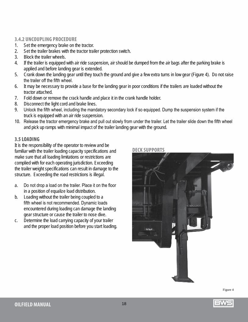
3.4.2 UNCOUPLING PROCEDURE1. Set the emergency brake on the tractor.2. Set the trailer brakes with the tractor trailer protection switch.3. Block the trailer wheels.4. If the trailer is equipped with air ride suspension, air should be dumped from the air bags after the parking brake is
applied and before landing gear is extended.5. Crank down the landing gear until they touch the ground and give a few extra turns in low gear (Figure 4). Do not raise
the trailer off the fifth wheel.6. It may be necessary to provide a base for the landing gear in poor conditions if the trailers are loaded without the
tractor attached.7. Fold down or remove the crack handle and place it in the crank handle holder.8. Disconnect the light cord and brake lines.9. Unlock the fifth wheel, including the mandatory secondary lock if so equipped. Dump the suspension system if the
truck is equipped with an air ride suspension.10. Release the tractor emergency brake and pull out slowly from under the trailer. Let the trailer slide down the fifth wheel
and pick up ramps with minimal impact of the trailer landing gear with the ground.
DECK SUPPORTS
Figure 4
3.5 LOADINGIt is the responsibility of the operator to review and be familiar with the trailer loading capacity specifications and make sure that all loading limitations or restrictions are complied with for each operating jurisdiction. Exceeding the trailer weight specifications can result in damage to the structure. Exceeding the road restrictions is illegal.
a. Do not drop a load on the trailer. Place it on the floor in a position of equalize load distribution.
b. Loading without the trailer being coupled to a fifth wheel is not recommended. Dynamic loads encountered during loading can damage the landing gear structure or cause the trailer to nose dive.
c. Determine the load carrying capacity of your trailer and the proper load position before you start loading.
19OILFIELD MANUAL
UNIFORM LOAD DISTRIBUTION FRONT TO BACK
UNIFORM LOAD DISTRIBUTION SIDE TO SIDE
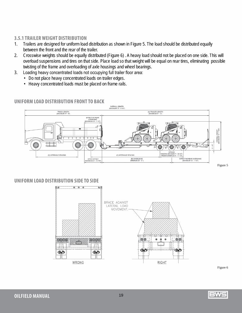
3.5.1 TRAILER WEIGHT DISTRIBUTION1. Trailers are designed for uniform load distribution as shown in Figure 5. The load should be distributed equally
between the front and the rear of the trailer.2. Crosswise weights should be equally distributed (Figure 6) . A heavy load should not be placed on one side. This will
overload suspensions and tires on that side. Place load so that weight will be equal on rear tires, eliminating possible twisting of the frame and overloading of axle housings and wheel bearings.
3. Loading heavy concentrated loads not occupying full trailer floor area:• Do not place heavy concentrated loads on trailer edges.• Heavy concentrated loads must be placed on frame rails.
Figure 6
Figure 5
20OILFIELD MANUAL
Figure 7A Figure 7B
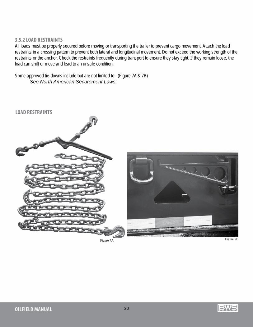
3.5.2 LOAD RESTRAINTSAll loads must be properly secured before moving or transporting the trailer to prevent cargo movement. Attach the load restraints in a crossing pattern to prevent both lateral and longitudinal movement. Do not exceed the working strength of the restraints or the anchor. Check the restraints frequently during transport to ensure they stay tight. If they remain loose, the load can shift or move and lead to an unsafe condition.
Some approved tie-downs include but are not limited to: (Figure 7A & 7B) See North American Securement Laws.
LOAD RESTRAINTS
21OILFIELD MANUAL
3.6.1 BRAKING GUIDELINESSafe, reliable and trouble-free operation of your trailer requires that the brakes be maintained in good operating condition. The improper use of brakes by the driver can contribute to shorter brake component life, result in system malfunctions, and cause poor tire wear patterns. The following list summarizes some basic operational guidelines for the driver.
1. Check the function of the brake system before starting a trip.2. Maintain a safe speed at all times. Slow down for rough, slippery, congested, or winding road conditions.3. Always provide sufficient vehicle spacing on the road to allow for safe stopping distance.4. Apply brakes gradually to produce an even deceleration until the vehicle is stopped.5. Watch traffic patterns ahead. Anticipate pattern changes that could result in an emergency. Apply the brakes gradually
in sufficient time to produce a controlled stop.6. Shift to a lower gear to use engine compression as the retarding force when going down steep grades.7. Do not apply brakes for a long period of time such as when traveling on a long downgrade. Light intermittent brake
application will result in proper vehicle control and keep brakes from overheating.8. Dry the brakes by applying them several times after going through water.9. Release the brakes just before going over railroad tracks or in other rough conditions. By allowing the wheels to turn
over rough road surfaces, there will be no shock loads to the brake system components and the possibility of flat spotting tires will be reduced.
10. Wet, icy or snow-packed surfaces require special care. Make sure ABS is functioning properly.11. Use wheel chocks, apply trailer and tractor parking brakes when parking the unit.12. When trailer-parking brakes are applied with hot drums, it may result in a cracked drum. Allow drums to cool before
applying the brakes.13. Fanning, or repeated on-and-off applications, will use up the system air reserves. This procedure is not recommended
with ABS. The wasting of air pressure reserves could result in insufficient air pressure should an emergency occur.14. Hard or panic stops can overheat the linings and drums. Overheating will cause brake fade. Severe overheating and
fade can result in the complete loss of braking capability. Overheating will also substantially reduce the expected life of brake components.
3.6 TRANSPORTINGAfter following the preceding instructions, your EZ-2-LOAD trailer unit is ready for transport. It is wise to review operating instructions periodically to refresh your memory. Good operation procedures result in a safe work environment for all.1. Ensure the trailer is securely attached and locked into position.2. Ensure the air lines are securely connected and have sufficient slack for turns.3. Ensure the brakes are properly adjusted and functioning adequately.4. Ensure the electrical harness is securely attached and all lights and reflectors are clean and in good working order.5. Ensure that the mud flaps are in good condition to minimize road splash in wet conditions.6. Always keep the trailer in good mechanical condition.7. Ensure the cargo is securely tied down.8. Always keep the trailer in good mechanical condition.9. Ensure the cargo is securely tied down.
22OILFIELD MANUAL
3.6.2 TIRESWhen operating the trailer, it is the responsibility of the driver to check the tires frequently. Inflation pressures, wear patterns and matching are critical parameters that must be monitored. The following factors affect tire life:
1. INSPECTION FREQUENCYTires should always be checked before the start of a run, twice during the day or every 4 hours, whichever comes first. It is also good practice to check the tires at each rest period during the day. When a driver hears or feels unusual handling characteristics, the first items to check are the tires. Problems found early can help avoid more serious problems later on. A sample of typical abnormal wear patterns are shown in the maintenance section of the tire wear problem before proceeding.
2. INFLATION PRESSURETires should always be operated at specified pressures. The tire is designed to run with the full width of the tread flat on the contact surface. Operating at other than specified pressures will change the tread contact patterns and dramatically shorten tire life. In addition, the tires will run hotter and can lead to blow-outs.
Check tire pressure when the tire is cold. A hot tire can read as much as 20 psi higher than a cold tire. If tires are over inflated, check for poor load distribution, uneven surface contact, over-loading or poor operating conditions. For inflation pressures, refer to manufacturers’ specifications.
3. TIRE MATCHINGDo not mix radial and bias-ply tires on the same axle. Their operating characteristics are different and will lead to uneven tire loading, rapid tire wear and adverse handling characteristics. Matching also includes combining tires that have the same amount of tread remaining. A tire with more tread has a larger rolling radius and will have to carry a heavier load. The best performance will be obtained when the rolling radius is within 1/8” for all tires on the axle.
23OILFIELD MANUAL
SINGLE AXLE BOOSTER OPERATING INSTRUCTIONS11SB1X
Park Single Axle Booster on a solid level surface that is a safe distance from any traffic or personnel. Level ground is required for verifying height and allowing correct connection process.
Chock Booster wheels so that it can not make any uncontrolled movement during the connection process.
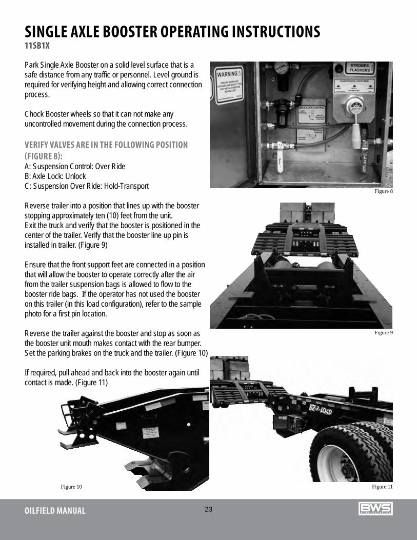
VERIFY VALVES ARE IN THE FOLLOWING POSITION (FIGURE 8):A: Suspension Control: Over RideB: Axle Lock: UnlockC: Suspension Over Ride: Hold-Transport
Reverse trailer into a position that lines up with the booster stopping approximately ten (10) feet from the unit.Exit the truck and verify that the booster is positioned in thecenter of the trailer. Verify that the booster line up pin is installed in trailer. (Figure 9)
Ensure that the front support feet are connected in a position that will allow the booster to operate correctly after the air from the trailer suspension bags is allowed to flow to the booster ride bags. If the operator has not used the booster on this trailer (in this load configuration), refer to the sample photo for a first pin location.
Reverse the trailer against the booster and stop as soon as the booster unit mouth makes contact with the rear bumper. Set the parking brakes on the truck and the trailer. (Figure 10)
If required, pull ahead and back into the booster again until contact is made. (Figure 11)
Figure 8
Figure 9
Figure 11Figure 10
24OILFIELD MANUAL
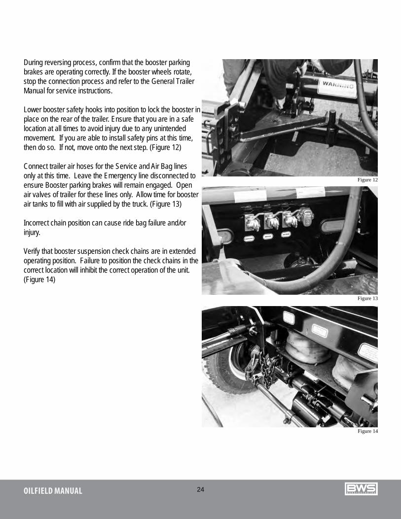
During reversing process, confirm that the booster parking brakes are operating correctly. If the booster wheels rotate, stop the connection process and refer to the General Trailer Manual for service instructions.
Lower booster safety hooks into position to lock the booster inplace on the rear of the trailer. Ensure that you are in a safelocation at all times to avoid injury due to any unintendedmovement. If you are able to install safety pins at this time, then do so. If not, move onto the next step. (Figure 12)
Connect trailer air hoses for the Service and Air Bag lines only at this time. Leave the Emergency line disconnected to ensure Booster parking brakes will remain engaged. Open air valves of trailer for these lines only. Allow time for booster air tanks to fill with air supplied by the truck. (Figure 13)
Incorrect chain position can cause ride bag failure and/or injury.
Verify that booster suspension check chains are in extended operating position. Failure to position the check chains in the correct location will inhibit the correct operation of the unit. (Figure 14)
Figure 12
Figure 13
Figure 14
25OILFIELD MANUAL
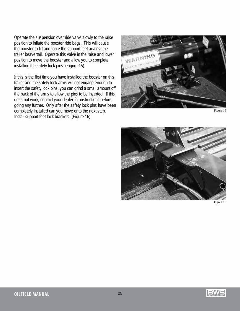
Operate the suspension over ride valve slowly to the raise position to inflate the booster ride bags. This will cause the booster to lift and force the support feet against the trailer beavertail. Operate this valve in the raise and lower position to move the booster and allow you to complete installing the safety lock pins. (Figure 15)
If this is the first time you have installed the booster on this trailer and the safety lock arms will not engage enough to insert the safety lock pins, you can grind a small amount off the back of the arms to allow the pins to be inserted. If this does not work, contact your dealer for instructions before going any further. Only after the safety lock pins have been completely installed can you move onto the next step.Install support feet lock brackets. (Figure 16)
Figure 15
Figure 16
26OILFIELD MANUAL
When this step is complete move the Suspension Over Ride Valve to the Hold Position.
Connect booster emergency air line to trailer and open valve. Connect booster electrical line to trailer.
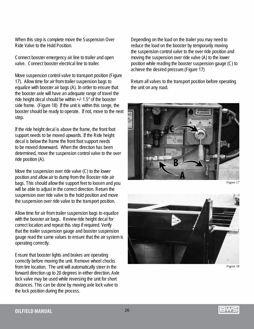
Move suspension control valve to transport position (Figure 17). Allow time for air from trailer suspension bags to equalize with booster air bags (A). In order to ensure that the booster axle will have an adequate range of travel the ride height decal should be within +/- 1.5” of the booster side frame. (Figure 18) If the unit is within this range, the booster should be ready to operate. If not, move to the next step.
If the ride height decal is above the frame, the front foot support needs to be moved upwards. If the Ride height decal is below the frame the front foot support needs to be moved downward. When the direction has been determined, move the suspension control valve to the over ride position (A).
Move the suspension over ride valve (C) to the lower position and allow air to dump from the Booster ride air bags. This should allow the support feet to loosen and you will be able to adjust in the correct direction. Return the suspension over ride valve to the hold position and move the suspension over ride valve to the transport position.
Allow time for air from trailer suspension bags to equalize with the booster air bags. Review ride height decal for correct location and repeat this step if required. Verify that the trailer suspension gauge and booster suspension gauge read the same values to ensure that the air system is operating correctly.
Ensure that booster lights and brakes are operating correctly before moving the unit. Remove wheel chocks from tire location. The unit will automatically steer in the forward direction up to 20 degrees in either direction. Axle lock valve may be used while reversing the unit for short distances. This can be done by moving axle lock valve to the lock position during the process.
Depending on the load on the trailer you may need to reduce the load on the booster by temporarily moving the suspension control valve to the over ride position and moving the suspension over ride valve (A) to the lower position while reading the booster suspension gauge (C) to achieve the desired pressure.(Figure 17)
Return all valves to the transport position before operating the unit on any road.
Figure 17A
B
C
Figure 18
27OILFIELD MANUAL
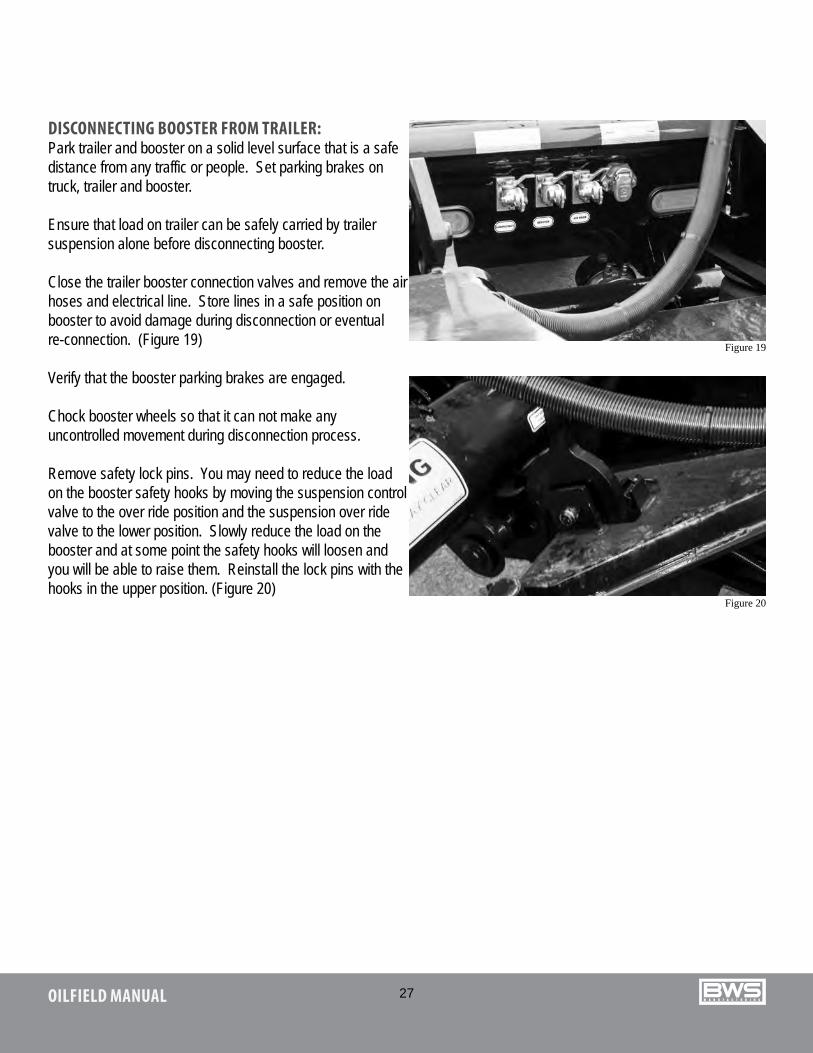
DISCONNECTING BOOSTER FROM TRAILER:Park trailer and booster on a solid level surface that is a safedistance from any traffic or people. Set parking brakes on truck, trailer and booster.
Ensure that load on trailer can be safely carried by trailer suspension alone before disconnecting booster.
Close the trailer booster connection valves and remove the airhoses and electrical line. Store lines in a safe position on booster to avoid damage during disconnection or eventual re-connection. (Figure 19)
Verify that the booster parking brakes are engaged.
Chock booster wheels so that it can not make any uncontrolled movement during disconnection process.
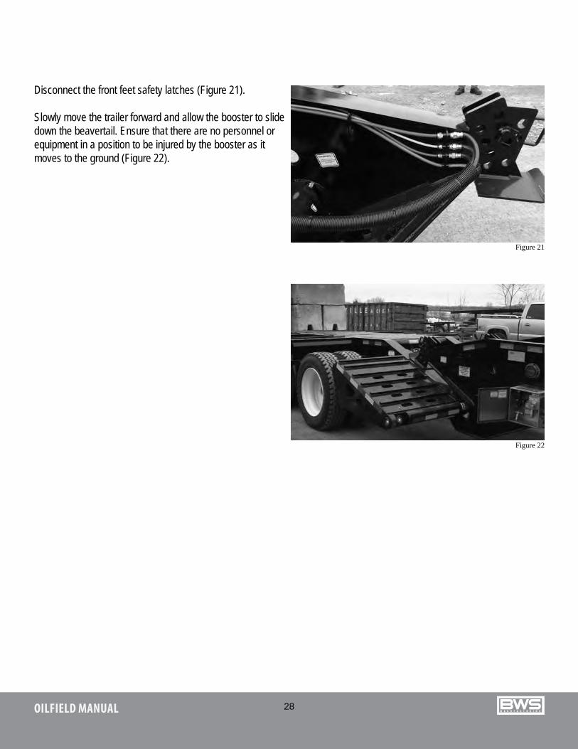
Remove safety lock pins. You may need to reduce the load on the booster safety hooks by moving the suspension control valve to the over ride position and the suspension over ride valve to the lower position. Slowly reduce the load on the booster and at some point the safety hooks will loosen and you will be able to raise them. Reinstall the lock pins with the hooks in the upper position. (Figure 20)
Figure 19
Figure 20
28OILFIELD MANUAL
Disconnect the front feet safety latches (Figure 21).
Slowly move the trailer forward and allow the booster to slidedown the beavertail. Ensure that there are no personnel or equipment in a position to be injured by the booster as it moves to the ground (Figure 22).
Figure 21
Figure 22

29OILFIELD MANUAL
SCISSORNECK OPERATION40SN3X
CHANGE FROM GOOSENECK TRAILER TO FLATBED:Activate parking brakes on truck and trailer. Connect winch cable to front of trailer and secure hook in eye plate. Adjust winch so there is light tension on the gooseneck. Disconnect trailer air and electrical lines. Place lines in gooseneck cavity so they will not be damaged during subsequent operations.Remove gooseneck pins on either side of trailer (Figure 24).
Release fifth wheel pin lock. Pull truck ahead slowly while releasing the winch line so that the trailer will disconnect from the fifth wheel and move over truck live roll in a controlled manner. As the truck moves ahead the trailer will straighten out in the
flatbed position.
Lower trailer to the ground with the winch while driving ahead far enough to allow it to flatten completely out (Figure 25).
At this point if you have a deck load for the trailer that is going to load over the gooseneck you can move the truck out of the way and complete the loading and securing of the cargo.
Reinstall the gooseneck pins in the flatbed position and secure with safety pins.
Ensure that the winch cable is securely connected to the trailer before attempting to reconnect the trailer to the truck. Operate the winch to raise the front of the trailer over the live roll on the truck and connect it securely to the truck fifth wheel.
Connect the trailer air and electrical lines to the truck.
CHANGE FROM FLATBED TRAILER TO GOOSENECK TRAILER:Reverse procedure detailed above.
Figure 23 Figure 24
Figure 25
30OILFIELD MANUAL
HYDRAULIC GOOSENECKHDG LH
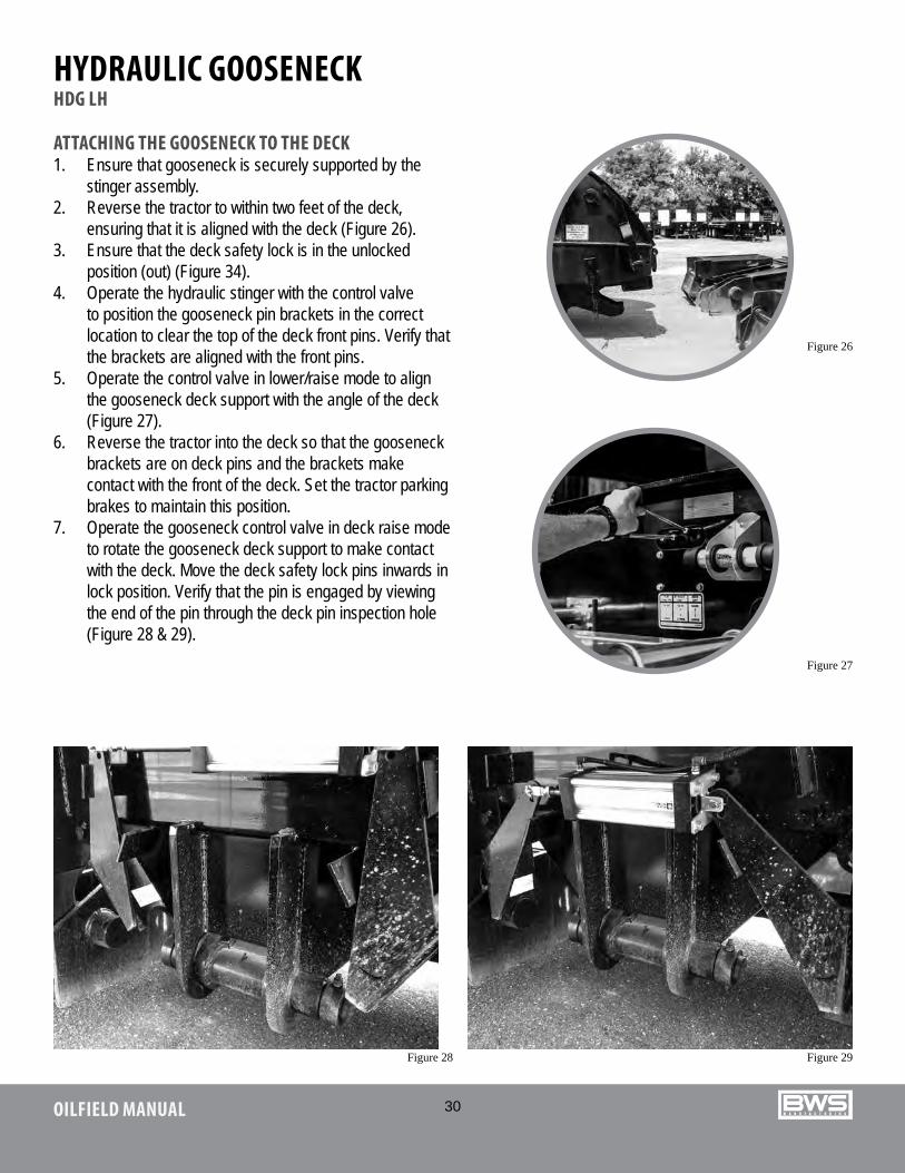
ATTACHING THE GOOSENECK TO THE DECK1. Ensure that gooseneck is securely supported by the
stinger assembly. 2. Reverse the tractor to within two feet of the deck,
ensuring that it is aligned with the deck (Figure 26).3. Ensure that the deck safety lock is in the unlocked
position (out) (Figure 34).4. Operate the hydraulic stinger with the control valve
to position the gooseneck pin brackets in the correct location to clear the top of the deck front pins. Verify that the brackets are aligned with the front pins.
5. Operate the control valve in lower/raise mode to align the gooseneck deck support with the angle of the deck (Figure 27).
6. Reverse the tractor into the deck so that the gooseneck brackets are on deck pins and the brackets make contact with the front of the deck. Set the tractor parking brakes to maintain this position.
7. Operate the gooseneck control valve in deck raise mode to rotate the gooseneck deck support to make contact with the deck. Move the deck safety lock pins inwards in lock position. Verify that the pin is engaged by viewing the end of the pin through the deck pin inspection hole (Figure 28 & 29).
Figure 26
Figure 27
Figure 28 Figure 29
31OILFIELD MANUAL
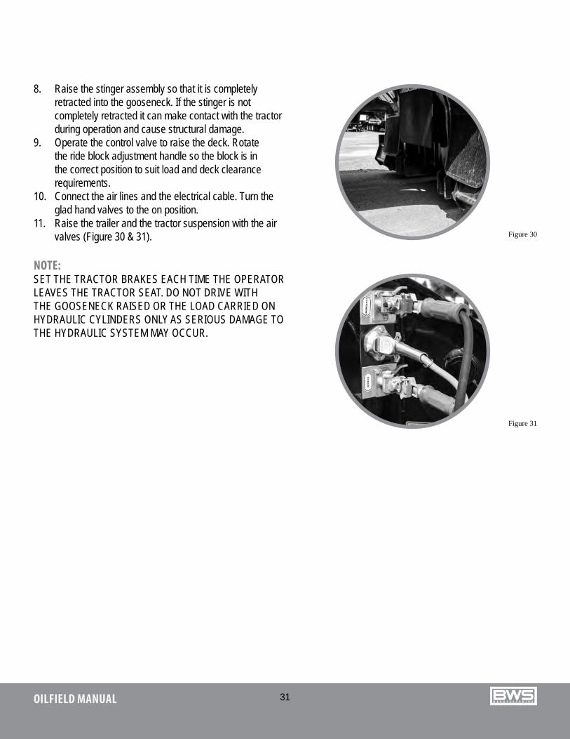
8. Raise the stinger assembly so that it is completely retracted into the gooseneck. If the stinger is not completely retracted it can make contact with the tractor during operation and cause structural damage.
9. Operate the control valve to raise the deck. Rotate the ride block adjustment handle so the block is in the correct position to suit load and deck clearance requirements.
10. Connect the air lines and the electrical cable. Turn the glad hand valves to the on position.
11. Raise the trailer and the tractor suspension with the air valves (Figure 30 & 31).
NOTE: SET THE TRACTOR BRAKES EACH TIME THE OPERATOR LEAVES THE TRACTOR SEAT. DO NOT DRIVE WITH THE GOOSENECK RAISED OR THE LOAD CARRIED ON HYDRAULIC CYLINDERS ONLY AS SERIOUS DAMAGE TO THE HYDRAULIC SYSTEM MAY OCCUR.
Figure 30
Figure 31
32OILFIELD MANUAL
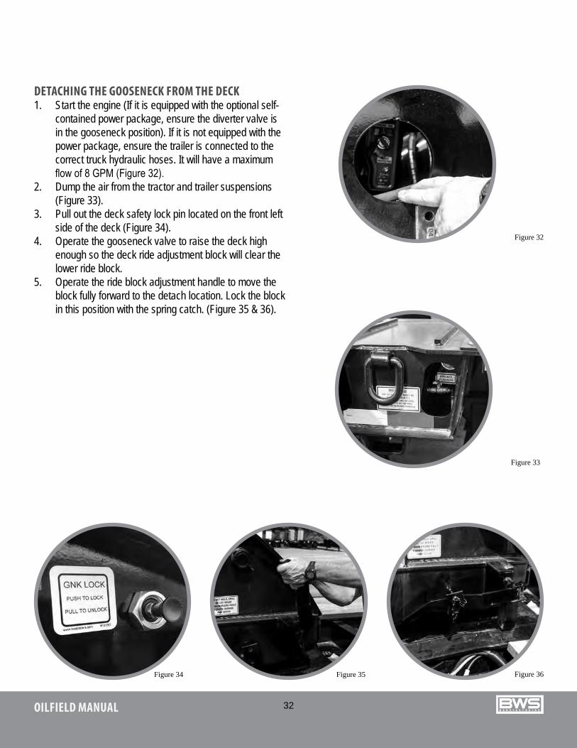
DETACHING THE GOOSENECK FROM THE DECK 1. Start the engine (If it is equipped with the optional self-
contained power package, ensure the diverter valve is in the gooseneck position). If it is not equipped with the power package, ensure the trailer is connected to the correct truck hydraulic hoses. It will have a maximum flow of 8 GPM (Figure 32).
2. Dump the air from the tractor and trailer suspensions (Figure 33).
3. Pull out the deck safety lock pin located on the front left side of the deck (Figure 34).
4. Operate the gooseneck valve to raise the deck high enough so the deck ride adjustment block will clear the lower ride block.
5. Operate the ride block adjustment handle to move the block fully forward to the detach location. Lock the block in this position with the spring catch. (Figure 35 & 36).
Figure 33
Figure 34 Figure 35 Figure 36
Figure 32
33OILFIELD MANUAL
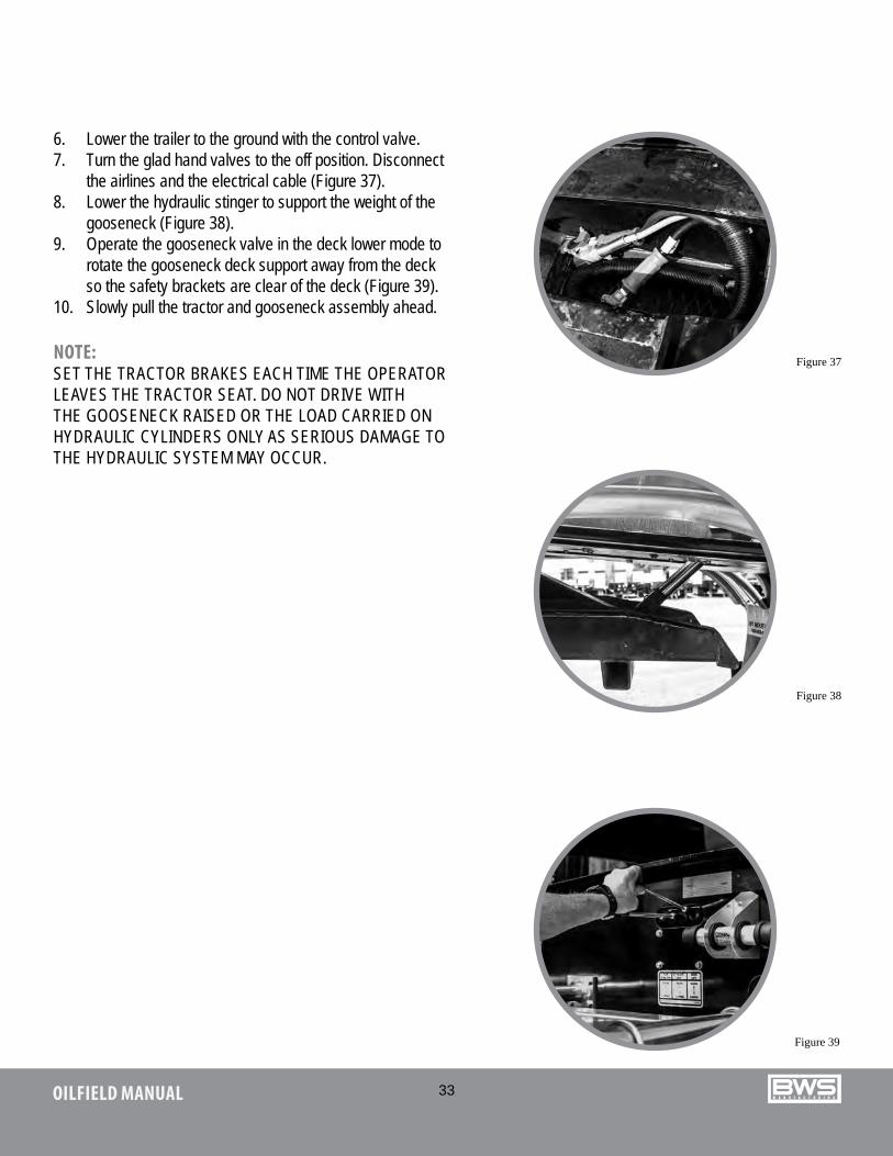
6. Lower the trailer to the ground with the control valve. 7. Turn the glad hand valves to the off position. Disconnect
the airlines and the electrical cable (Figure 37). 8. Lower the hydraulic stinger to support the weight of the
gooseneck (Figure 38). 9. Operate the gooseneck valve in the deck lower mode to
rotate the gooseneck deck support away from the deck so the safety brackets are clear of the deck (Figure 39).
10. Slowly pull the tractor and gooseneck assembly ahead.
NOTE: SET THE TRACTOR BRAKES EACH TIME THE OPERATOR LEAVES THE TRACTOR SEAT. DO NOT DRIVE WITH THE GOOSENECK RAISED OR THE LOAD CARRIED ON HYDRAULIC CYLINDERS ONLY AS SERIOUS DAMAGE TO THE HYDRAULIC SYSTEM MAY OCCUR.
Figure 37
Figure 38
Figure 39

34OILFIELD MANUAL
DETACHING THE TRACTOR FROM THE TRAILER: 1. Start the engine (if it is equipped with the optional, self-contained power package, ensure the diverter valve is in the
gooseneck position). If it is not equipped with the power pack, ensure the trailer is connected to the correct truck hydraulic hoses. The maximum flow is 8 GPM.
2. Dump the air from the tractor and trailer suspensions.3. Ensure that the safety lock pin is engaged to avoid structural damage or personnel injury when the tractor is removed
from the trailer. 4. Operate the gooseneck valve to raise the deck high enough so the deck ride adjustment block will clear the lower ride
block. 5. Operate the ride block adjustment handle to move the block fully forward to detach location. Lock the block in this
position with the spring catch.6. Lower the trailer to the ground with the control valve and remove the load from the tractor.7. Disconnect the airlines, electrical cable and hydraulic lines from the front of the gooseneck.8. Release the tractor fifth wheel pin and pull the tractor forward to disconnect it from the trailer.
ATTACHING THE TRACTOR TO THE TRAILER:1. Dump the suspension air in the tractor. 2. Set the fifth wheel lock to the open position and reverse the tractor close to the trailer.3. If the trailer gooseneck is not at the appropriate height for connection, the hydraulic lines can be connected and the
gooseneck position can be adjusted correctly with the control valve. 4. Reverse the tractor back into the trailer to lock the fifth wheel pin. 5. Connect the air lines, electrical cable and hydraulic lines. 6. Operate the control valve to raise the deck high enough to engage the ride block in the required position. 7. Rotate the ride block adjustment handle so that block is correctly positioned to suit the load and deck clearance
requirements. 8. Raise the trailer and tractor suspension with the air valves.

35OILFIELD MANUAL
OPERATING INSTRUCTIONS FOR ATTACHING AND DETACHING HYDRAULIC GOOSENECK FLOAT1. Start the engine (If it is equipped with optional self-contained power package).2. Raise the gooseneck with the control valve up.3. Unlock and rotate the paddle handle to rotate the paddles away from the deck.4. Pull the gooseneck lock out to unlock the gooseneck.5. Lower the trailer to the ground with the control valve. 6. Lower the hydraulic stinger to support the weight of the gooseneck.7. Disconnect the airlines and electrical cable then turn the glad hands to the off position.8. Slowly pull the tractor and gooseneck assembly ahead, making sure that the tower clears the deck hooks.9. To recouple, reverse the above procedure.
NOTE: Do not drive with the gooseneck raised and the load carried on the hydraulic cylinders only, as serious damage to the hydraulic system may occur.
36OILFIELD MANUAL
MAINTENANCE AND INSPECTION
The safe and efficient operation of your EZ-2-LOAD trailer will depend a great deal on your diligence in following the maintenance and adjustment procedures outlined in this section. If you follow these recommendations your EZ-2-LOAD trailer will work to its full potential. With adequate attention to regular and preventative maintenance your costs can be reduced significantly.
The various components and systems of your EZ-2-LOAD trailer, which will require daily and/or periodic inspections, maintenance and adjustments are presented in this section.
MAINTENANCE AND INSPECTION SUMMARYCOMPONENT FREQUENCY INSPECTIONKingpin 30,000 mile/50,000 km or every 3 months Kingpin wear and no damage to
anchoring
Fifth Wheel 30,000 mile/50,000 km or every 3 months Hardware tight and kingpin lock clearance
Wheel Bearing 25,000 mile/40,000 km or every 3 months Remove wheel for seal leaks, end play, bearing condition and cleanliness
Hub Oil Daily Check oil level
Oil Seals Daily Check for leaks and replace seals when leaks occur or wheel removed
Brakes 25,000 mile/40,000 km Check lining wear. Check brake adjustments.
1000,000 mile/150,000 km Re-line as required
37OILFIELD MANUAL
COMPONENT FREQUENCY INSPECTIONWheels Daily Check for wobbles, cracked or bent
rims and for loose, missing, broken stripped or otherwise ineffective fasteners.
Tires Daily Tire pressureWear patterns
Axles As required Alignment to chassis
SUSPENSIONAir Ride Suspension Daily, also see section 4.13 Air leakage
Hardware tightnessMechanicalHeight check
AIR SYSTEMRelay Emergency Valve Every 3 to 6 months Perform operating and leakage testsGlad Hands Daily Check for cracks, worn or damaged
componentsSpring Brake Valve Annually or 100,000 mile/150,000 km Perform operating and leakage testsRelay Valve Annually or 100,000 mile/150,000 km Perform operating and leakage testsReservoir Daily
Every 6 monthsDrain air tanksIntegral check value function
Air Lines / Hoses Daily Check for leaks, chafing, kinking or other mechanical damage
Electrical System Daily Check for burned out bulbs and loose connections
38OILFIELD MANUAL
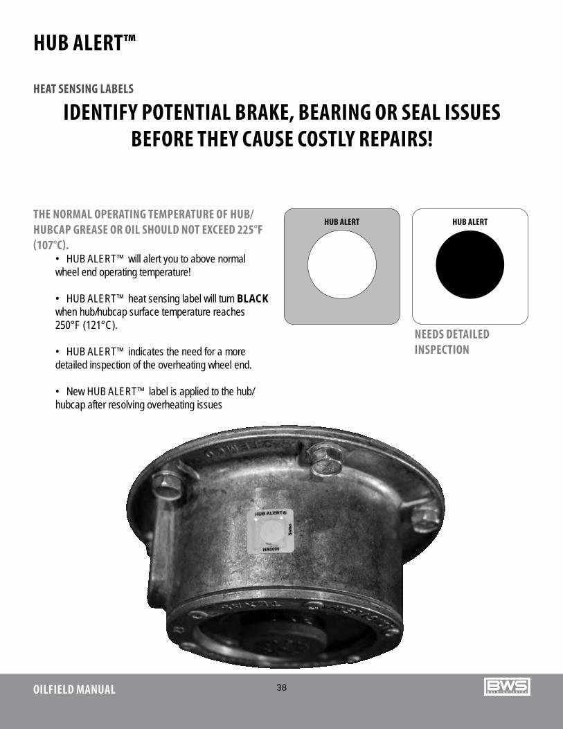
HUB ALERT™
HEAT SENSING LABELS
IDENTIFY POTENTIAL BRAKE, BEARING OR SEAL ISSUES BEFORE THEY CAUSE COSTLY REPAIRS!
THE NORMAL OPERATING TEMPERATURE OF HUB/HUBCAP GREASE OR OIL SHOULD NOT EXCEED 225°F (107°C).
• HUB ALERT™ will alert you to above normal wheel end operating temperature!
• HUB ALERT™ heat sensing label will turn BLACK when hub/hubcap surface temperature reaches 250°F (121°C).
• HUB ALERT™ indicates the need for a more detailed inspection of the overheating wheel end.
• New HUB ALERT™ label is applied to the hub/hubcap after resolving overheating issues
NEEDS DETAILED INSPECTION
39OILFIELD MANUAL
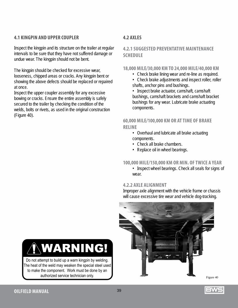
4.1 KINGPIN AND UPPER COUPLER
Inspect the kingpin and its structure on the trailer at regular intervals to be sure that they have not suffered damage or undue wear. The kingpin should not be bent.
The kingpin should be checked for excessive wear, looseness, chipped areas or cracks. Any kingpin bent or showing the above defects should be replaced or repaired at once. Inspect the upper coupler assembly for any excessive bowing or cracks. Ensure the entire assembly is safely secured to the trailer by checking the condition of the welds, bolts or rivets, as used in the original construction (Figure 40).
Figure 40
4.2 AXLES
4.2.1 SUGGESTED PREVENTATIVE MAINTENANCE SCHEDULE
18,000 MILE/30,000 KM TO 24,000 MILE/40,000 KM• Check brake lining wear and re-line as required.• Check brake adjustments and inspect roller, roller shafts, anchor pins and bushings.• Inspect brake actuator, camshaft, camshaft bushings, camshaft brackets and camshaft bracket bushings for any wear. Lubricate brake actuating components.
60,000 MILE/100,000 KM OR AT TIME OF BRAKE RELINE
• Overhaul and lubricate all brake actuating components.• Check all brake chambers.• Replace oil in wheel bearings.
100,000 MILE/150,000 KM OR MIN. OF TWICE A YEAR• Inspect wheel bearings. Check all seals for signs of wear.
4.2.2 AXLE ALIGNMENTImproper axle alignment with the vehicle frame or chassis will cause excessive tire wear and vehicle dog-tracking.
40OILFIELD MANUAL
Proper axle alignment is a vital part of your operation(maintenance) and should be checked on a regular basis.
Each EZ-2-LOAD trailer is checked for correct alignment before it leaves the factory, but settlement of suspension may necessitate realignment after first 500 miles / 800 km.
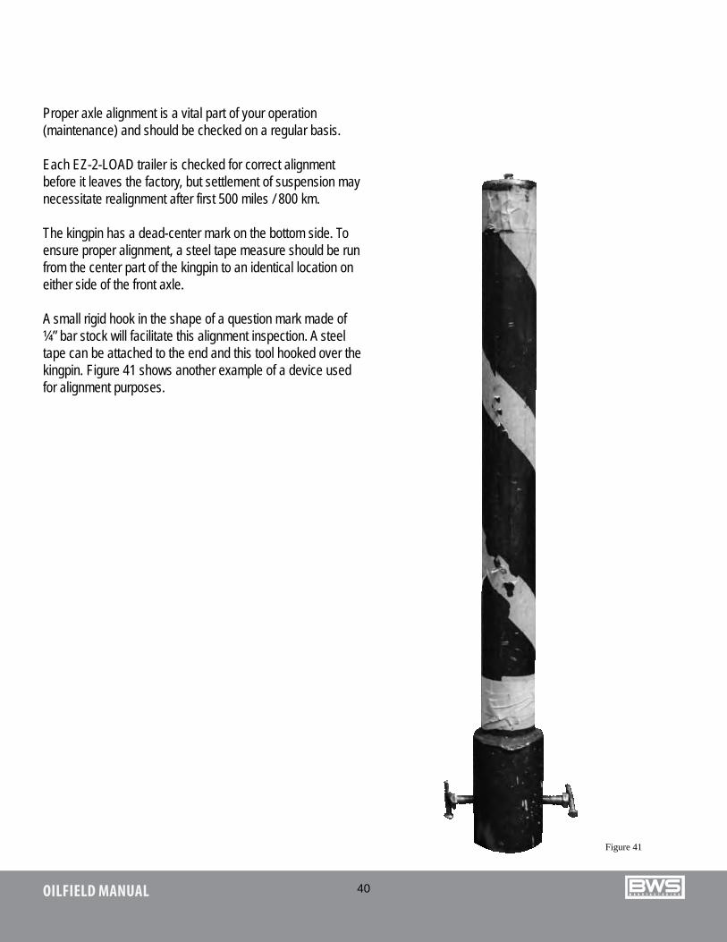
The kingpin has a dead-center mark on the bottom side. To ensure proper alignment, a steel tape measure should be run from the center part of the kingpin to an identical location on either side of the front axle.
A small rigid hook in the shape of a question mark made of ¼” bar stock will facilitate this alignment inspection. A steel tape can be attached to the end and this tool hooked over the kingpin. Figure 41 shows another example of a device used for alignment purposes.
Figure 41
41OILFIELD MANUAL
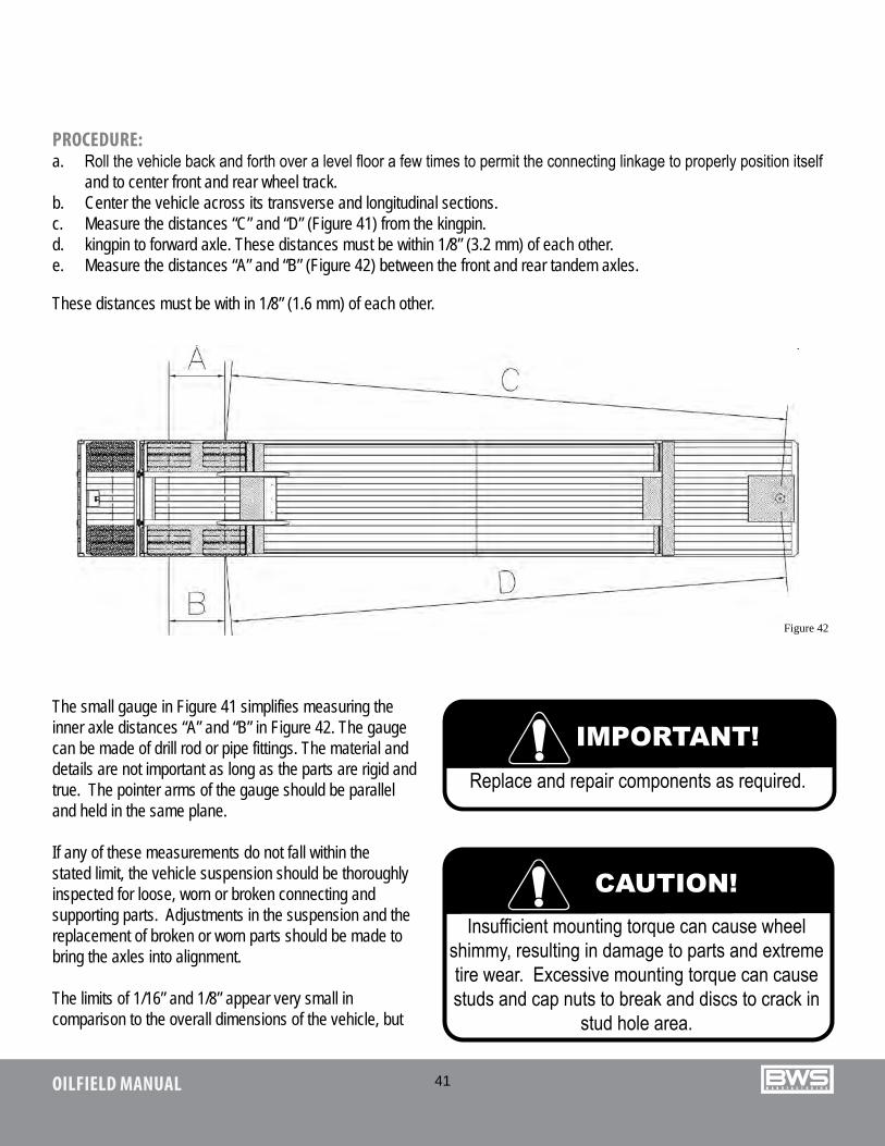
PROCEDURE:a. Roll the vehicle back and forth over a level floor a few times to permit the connecting linkage to properly position itself
and to center front and rear wheel track.b. Center the vehicle across its transverse and longitudinal sections.c. Measure the distances “C” and “D” (Figure 41) from the kingpin.d. kingpin to forward axle. These distances must be within 1/8” (3.2 mm) of each other.e. Measure the distances “A” and “B” (Figure 42) between the front and rear tandem axles.
These distances must be with in 1/8” (1.6 mm) of each other.
Figure 42
The small gauge in Figure 41 simplifies measuring the inner axle distances “A” and “B” in Figure 42. The gauge can be made of drill rod or pipe fittings. The material and details are not important as long as the parts are rigid and true. The pointer arms of the gauge should be parallel and held in the same plane.
If any of these measurements do not fall within the stated limit, the vehicle suspension should be thoroughly inspected for loose, worn or broken connecting and supporting parts. Adjustments in the suspension and the replacement of broken or worn parts should be made to bring the axles into alignment.
The limits of 1/16” and 1/8” appear very small in comparison to the overall dimensions of the vehicle, but
42OILFIELD MANUAL
they are recognized as the maximum permissible variation. The relatively small size of these limits make it important that measurements be accurate.
Failure to keep the axles properly aligned may cause tire scrub and suspension component strain.
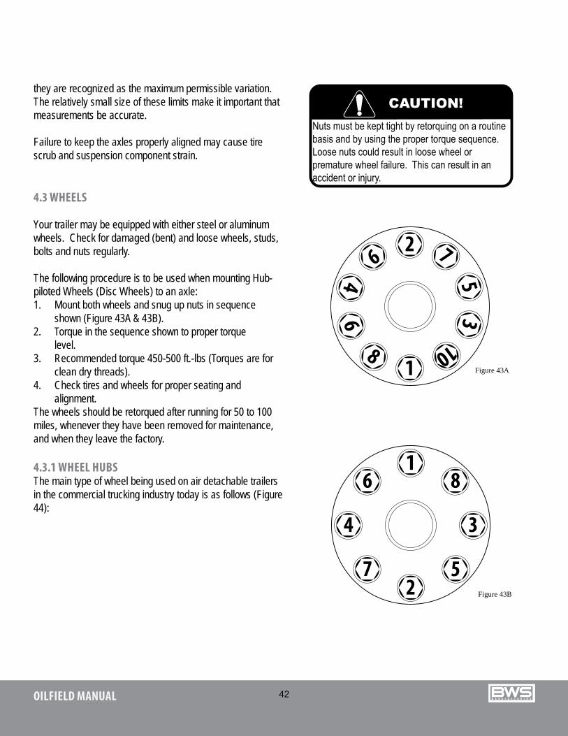
4.3 WHEELS
Your trailer may be equipped with either steel or aluminum wheels. Check for damaged (bent) and loose wheels, studs, bolts and nuts regularly.
The following procedure is to be used when mounting Hub-piloted Wheels (Disc Wheels) to an axle:1. Mount both wheels and snug up nuts in sequence
shown (Figure 43A & 43B).2. Torque in the sequence shown to proper torque
level.3. Recommended torque 450-500 ft.-lbs (Torques are for
clean dry threads).4. Check tires and wheels for proper seating and
alignment.The wheels should be retorqued after running for 50 to 100 miles, whenever they have been removed for maintenance, and when they leave the factory.
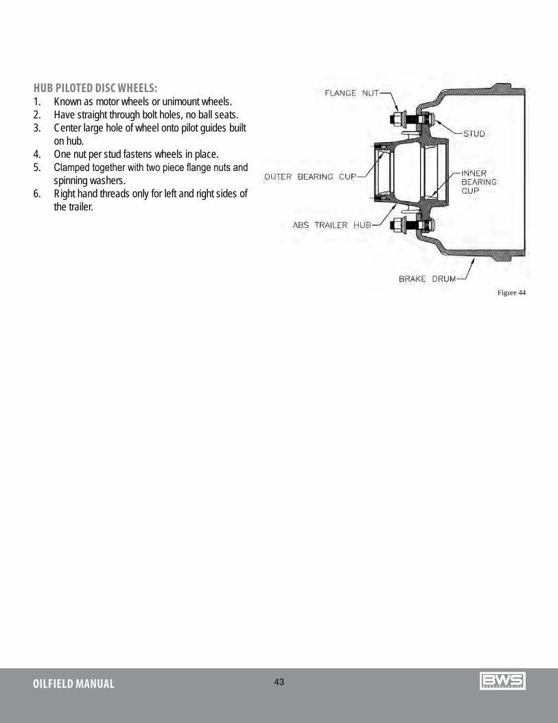
4.3.1 WHEEL HUBSThe main type of wheel being used on air detachable trailers in the commercial trucking industry today is as follows (Figure 44):
1
26
5
8
7
4
3
9
10
61
8
3
52
7
4
Figure 43A
Figure 43B
43OILFIELD MANUAL
HUB PILOTED DISC WHEELS:1. Known as motor wheels or unimount wheels.2. Have straight through bolt holes, no ball seats.3. Center large hole of wheel onto pilot guides built
on hub.4. One nut per stud fastens wheels in place.5. Clamped together with two piece flange nuts and
spinning washers.6. Right hand threads only for left and right sides of
the trailer.
Figure 44
44OILFIELD MANUAL
4.4.1 BEARING ADJUSTMENT PROCEDURETMC’s Wheel End task force (The Maintenance Council task force on tractor-trailer communications) developed the following bearing adjustment recommendations. It represents the combined input of manufacturers of wheel end components.
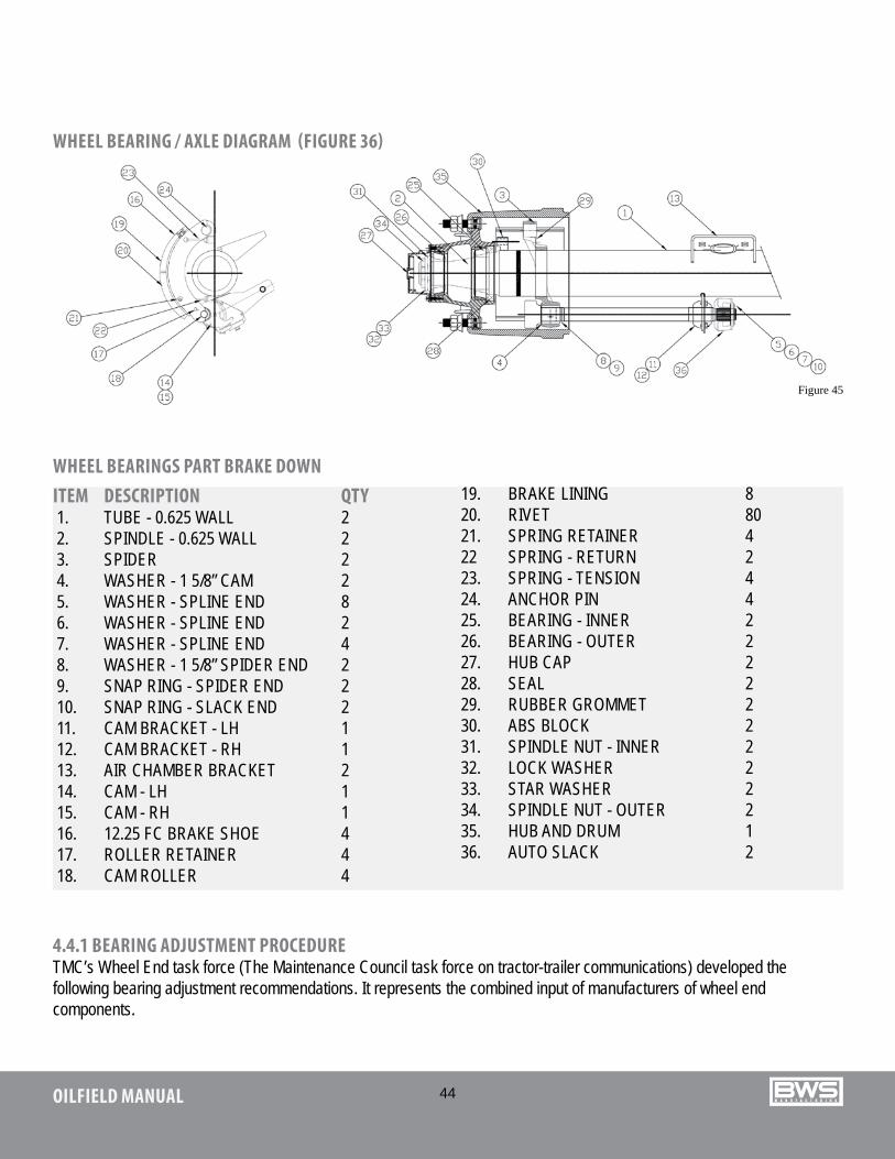
WHEEL BEARING / AXLE DIAGRAM (FIGURE 36)
WHEEL BEARINGS PART BRAKE DOWNITEM DESCRIPTION QTY 1. TUBE - 0.625 WALL 2 2. SPINDLE - 0.625 WALL 2 3. SPIDER 2 4. WASHER - 1 5/8” CAM 2 5. WASHER - SPLINE END 8 6. WASHER - SPLINE END 2 7. WASHER - SPLINE END 4 8. WASHER - 1 5/8” SPIDER END 2 9. SNAP RING - SPIDER END 2 10. SNAP RING - SLACK END 2 11. CAM BRACKET - LH 1 12. CAM BRACKET - RH 1 13. AIR CHAMBER BRACKET 2 14. CAM - LH 1 15. CAM - RH 1 16. 12.25 FC BRAKE SHOE 4 17. ROLLER RETAINER 4 18. CAM ROLLER 4
19. BRAKE LINING 8 20. RIVET 80 21. SPRING RETAINER 4 22 SPRING - RETURN 2 23. SPRING - TENSION 4 24. ANCHOR PIN 4 25. BEARING - INNER 2 26. BEARING - OUTER 2 27. HUB CAP 2 28. SEAL 2 29. RUBBER GROMMET 2 30. ABS BLOCK 2 31. SPINDLE NUT - INNER 2 32. LOCK WASHER 2 33. STAR WASHER 2 34. SPINDLE NUT - OUTER 2 35. HUB AND DRUM 1 36. AUTO SLACK 2
Figure 45
45OILFIELD MANUAL
STEP 1 BEARING LUBRICATIONLubricate the wheel bearing with clean lubricant of the same type, as used in the axle sump or hub assembly.
STEP 2Initial adjusting nut torque adjustment (while rotating the wheel) tighten the adjusting nut to a torque of 200 ft.lbs.
STEP 3 INITIAL BACK-OFFBack the adjusting nut off one full turn.
STEP 4 FINAL ADJUSTING NUT TORQUETighten the adjusting nut to a final torque of 100 ft.lbs while rotating the wheel.
STEP 5 FINAL BACK-OFFBack the adjusting nut off 1/8 to 1/4 turn (app. 0.003 inches)
Note: For self-locking nut systems consult manufacturers’ specifications. BWS assumes no responsibility for bearing warranty.
Acceptable end play is .001”-.005” As measured with a dial indicator.
Note: Loose wheel bearings are the major cause of seal leakage. Be sure bearing tolerance is correct.
4.4.2 BEARING ADJUSTMENTBearings must be correctly adjusted and properly lubricated to achieve maximum bearing life and to prevent damage to wheels, axles, and possibly the trailer. The bearings should be lubricated at regular intervals, depending on vehicle speeds, loads and general operating conditions. Changes of wheel bearing lubricants are recommended every 20,000 – 25,000 miles, or twice a year (Spring & Fall).
Remove wheel assembly and bearing cones. Clean all old lube from hub of wheel bearings & hubcap with a good grade commercial cleaner and a stiff brush, not steel. DO NOT use gasoline or air hose in cleaning operation. Avoid spinning cone while cleaning.
Allow the cleaned parts to dry and wipe them up with a clean, absorbent cloth or paper towel. Clean all tools used in the service operation.
Note: Grease will not adhere to a surface that is wetwith solvent because the solvent may dilute the lubricant.
Cleanliness is most important. Contamination may damage the bearing components.
Inspect seals and seal spring surfaces, bearing cups and bearing cones for indications of wear or damage. Handle all parts carefully during inspection and packaging so the cage will not be bent or the rollers and cone damaged.
Place bearing cones in cups and check for proper fit, and proper number.
Oil lubricated bearings – Use a gear type oil SAE-90 and spread a light coat of oil on all parts before assembly.
To prevent “Hot” bearings and provide for maximum load carrying capacity, bearings should be kept free of “slack” and “play”. For positive close adjustment, a torque wrench should be used to tighten the bearing to the manufacturers’ specifications.
Note: It is recommended to replace axle seals each time wheel ends are serviced.
The following procedure will provide for satisfactory bearing adjustment when the torque method is not feasible. It should be noted that whenever wheels, hubs and drums are removed for any purpose, the bearings will require re-adjustment.
With the wheel raised off the ground and the component parts on the spindle, the inner spindle nut should be tightened until there is no “slack” or “play” in the bearings. The inner nut should then be backed-off approximately one-half turn. The lock (thrust) washer is then placed in position. Next, the outer spindle nut is tightened against the washer.
Once the procedure is completed, the bearings should
46OILFIELD MANUAL
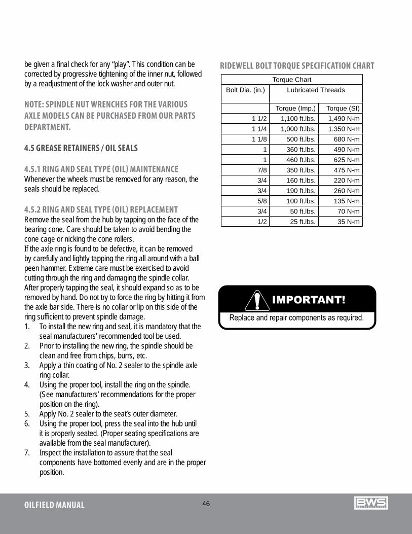
RIDEWELL BOLT TORQUE SPECIFICATION CHARTTorque Chart
Bolt Dia. (in.) Lubricated Threads
Torque (Imp.) Torque (SI)1 1/2 1,100 ft.lbs. 1,490 N-m1 1/4 1,000 ft.lbs. 1.350 N-m1 1/8 500 ft.lbs. 680 N-m
1 360 ft.lbs. 490 N-m1 460 ft.lbs. 625 N-m
7/8 350 ft.lbs. 475 N-m 3/4 160 ft.lbs. 220 N-m 3/4 190 ft.lbs. 260 N-m 5/8 100 ft.lbs. 135 N-m 3/4 50 ft.lbs. 70 N-m 1/2 25 ft.lbs. 35 N-m
be given a final check for any “play”. This condition can be corrected by progressive tightening of the inner nut, followed by a readjustment of the lock washer and outer nut.
NOTE: SPINDLE NUT WRENCHES FOR THE VARIOUS AXLE MODELS CAN BE PURCHASED FROM OUR PARTS DEPARTMENT.
4.5 GREASE RETAINERS / OIL SEALS
4.5.1 RING AND SEAL TYPE (OIL) MAINTENANCEWhenever the wheels must be removed for any reason, the seals should be replaced.
4.5.2 RING AND SEAL TYPE (OIL) REPLACEMENTRemove the seal from the hub by tapping on the face of the bearing cone. Care should be taken to avoid bending the cone cage or nicking the cone rollers.If the axle ring is found to be defective, it can be removed by carefully and lightly tapping the ring all around with a ball peen hammer. Extreme care must be exercised to avoid cutting through the ring and damaging the spindle collar. After properly tapping the seal, it should expand so as to be removed by hand. Do not try to force the ring by hitting it from the axle bar side. There is no collar or lip on this side of the ring sufficient to prevent spindle damage.1. To install the new ring and seal, it is mandatory that the
seal manufacturers’ recommended tool be used.2. Prior to installing the new ring, the spindle should be
clean and free from chips, burrs, etc.3. Apply a thin coating of No. 2 sealer to the spindle axle
ring collar.4. Using the proper tool, install the ring on the spindle.
(See manufacturers’ recommendations for the proper position on the ring).
5. Apply No. 2 sealer to the seat’s outer diameter.6. Using the proper tool, press the seal into the hub until
it is properly seated. (Proper seating specifications are available from the seal manufacturer).
7. Inspect the installation to assure that the seal components have bottomed evenly and are in the proper position.
47OILFIELD MANUAL
4.6 SUSPENSION SYSTEM (AIR)
The axles are attached to and carried by the suspension system. The EZ-2-LOAD trailer uses an air ride suspension system.
Each must be kept tight and in good working order to obtain maximum performance and life. Following are EZ-2-LOAD suspension service and maintenance procedures to use.
4.6.1 INSPECTION1. FREQUENCYa. During pre-delivery inspection.b. After first 500 miles / 800 km of operation.
2. ACTION• Check that all fasteners are tightened to their specific torque (Figures 37, 38 & 39).• Check for damaged or broken components.• Check all suspension system and axle welds or cracks.• Evaluate tire wear patterns. Use the wear patterns as a guide to determine if maintenance or adjustments are required on the suspension system.• Check the alignment of the axles.• Ensure air pressure is being maintained at a pressure greater than 65 psi
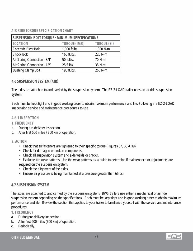
AIR RIDE TORQUE SPECIFICATION CHART
SUSPENSION BOLT TORQUE - MINIMUM SPECIFICATIONSLOCATION TORQUE (IMP.) TORQUE (SI)Eccentric Pivot Bolt 1,000 ft.lbs. 1,350 N-mShock Bolt 160 ft.lbs. 220 N-mAir Spring Connection - 3/4” 50 ft.lbs. 70 N-mAir Spring Connection - 1/2” 25 ft.lbs. 35 N-mBushing Clamp Bolt 190 ft.lbs. 260 N-m
4.7 SUSPENSION SYSTEM
The axles are attached to and carried by the suspension system. BWS trailers use either a mechanical or air ride suspension system depending on the specifications. Each must be kept tight and in good working order to obtain maximum performance and life. Review the section that applies to your trailer to familiarize yourself with the service and maintenance procedures.1. FREQUENCYa. During pre-delivery inspection.b. After first 500 miles (800 km) of operation.c. Periodically.
48OILFIELD MANUAL
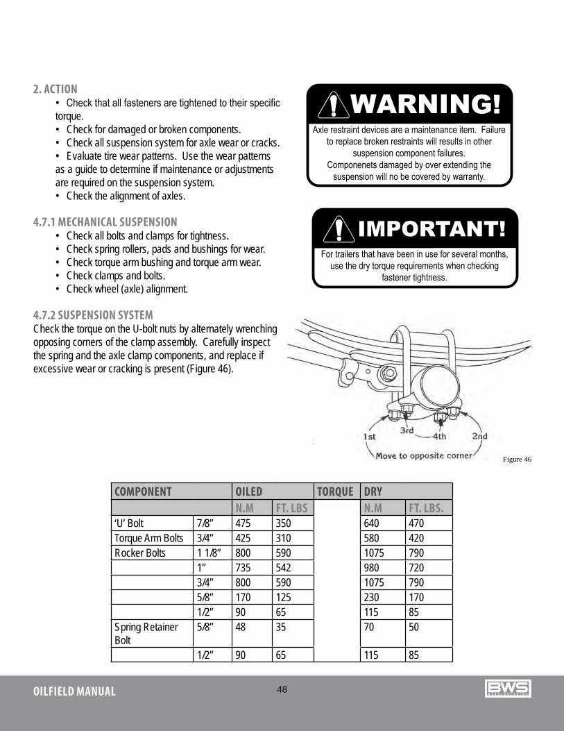
Figure 46
COMPONENT OILED TORQUE DRYN.M FT. LBS N.M FT. LBS.
‘U’ Bolt 7/8” 475 350 640 470Torque Arm Bolts 3/4” 425 310 580 420Rocker Bolts 1 1/8” 800 590 1075 790
1” 735 542 980 7203/4” 800 590 1075 7905/8” 170 125 230 1701/2” 90 65 115 85
Spring Retainer Bolt
5/8” 48 35 70 50
1/2” 90 65 115 85
2. ACTION• Check that all fasteners are tightened to their specific torque.• Check for damaged or broken components.• Check all suspension system for axle wear or cracks.• Evaluate tire wear patterns. Use the wear patterns as a guide to determine if maintenance or adjustments are required on the suspension system.• Check the alignment of axles.
4.7.1 MECHANICAL SUSPENSION• Check all bolts and clamps for tightness.• Check spring rollers, pads and bushings for wear.• Check torque arm bushing and torque arm wear.• Check clamps and bolts. • Check wheel (axle) alignment.
4.7.2 SUSPENSION SYSTEMCheck the torque on the U-bolt nuts by alternately wrenching opposing corners of the clamp assembly. Carefully inspect the spring and the axle clamp components, and replace if excessive wear or cracking is present (Figure 46).
49OILFIELD MANUAL
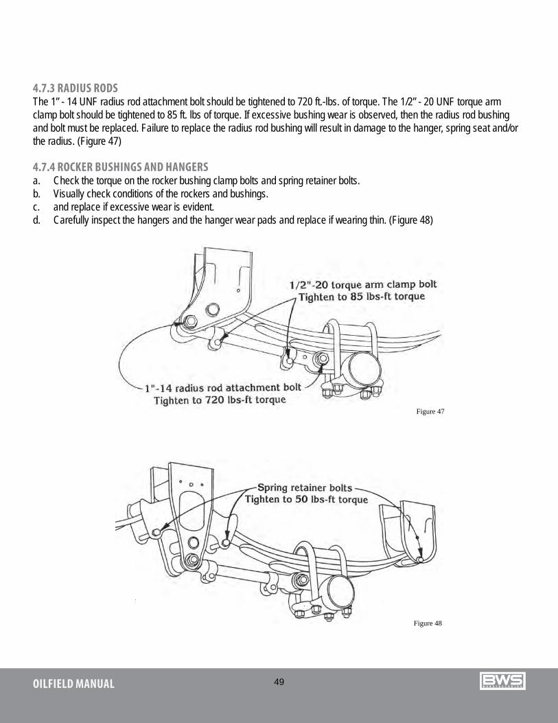
4.7.3 RADIUS RODSThe 1” - 14 UNF radius rod attachment bolt should be tightened to 720 ft.-lbs. of torque. The 1/2” - 20 UNF torque arm clamp bolt should be tightened to 85 ft. lbs of torque. If excessive bushing wear is observed, then the radius rod bushing and bolt must be replaced. Failure to replace the radius rod bushing will result in damage to the hanger, spring seat and/or the radius. (Figure 47)
4.7.4 ROCKER BUSHINGS AND HANGERSa. Check the torque on the rocker bushing clamp bolts and spring retainer bolts.b. Visually check conditions of the rockers and bushings.c. and replace if excessive wear is evident.d. Carefully inspect the hangers and the hanger wear pads and replace if wearing thin. (Figure 48)
Figure 47
Figure 48
50OILFIELD MANUAL
AIR RIDE SUSPENSION ASSEMBLY
Figure 49
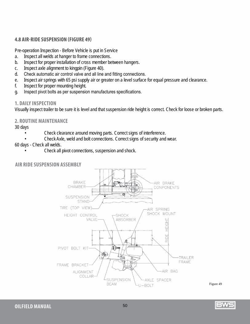
4.8 AIR-RIDE SUSPENSION (FIGURE 49)
Pre-operation Inspection - Before Vehicle is put in Servicea. Inspect all welds at hanger to frame connections.b. Inspect for proper installation of cross member between hangers.c. Inspect axle alignment to kingpin (Figure 40).d. Check automatic air control valve and all line and fitting connections.e. Inspect air springs with 65 psi supply air or greater on a level surface for equal pressure and clearance.f. Inspect for proper mounting height.g. Inspect pivot bolts as per suspension manufactures specifications.
1. DAILY INSPECTIONVisually inspect trailer to be sure it is level and that suspension ride height is correct. Check for loose or broken parts.
2. ROUTINE MAINTENANCE30 days
• Check clearance around moving parts. Correct signs of interference.• Check Axle, weld and bolt connections. Correct signs of security and wear.
60 days - Check all welds.• Check all pivot connections, suspension and shock.
51OILFIELD MANUAL
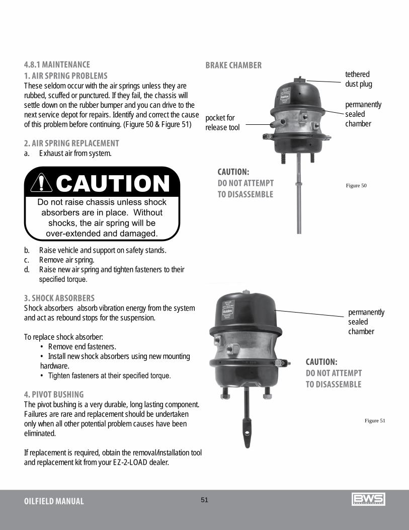
4.8.1 MAINTENANCE1. AIR SPRING PROBLEMS These seldom occur with the air springs unless they are rubbed, scuffed or punctured. If they fail, the chassis will settle down on the rubber bumper and you can drive to the next service depot for repairs. Identify and correct the cause of this problem before continuing. (Figure 50 & Figure 51)
2. AIR SPRING REPLACEMENTa. Exhaust air from system.
BRAKE CHAMBER
Figure 50
Figure 51
b. Raise vehicle and support on safety stands.c. Remove air spring.d. Raise new air spring and tighten fasteners to their
specified torque.
3. SHOCK ABSORBERSShock absorbers absorb vibration energy from the system and act as rebound stops for the suspension.
To replace shock absorber:• Remove end fasteners.• Install new shock absorbers using new mounting hardware.• Tighten fasteners at their specified torque.
4. PIVOT BUSHINGThe pivot bushing is a very durable, long lasting component. Failures are rare and replacement should be undertaken only when all other potential problem causes have been eliminated.
If replacement is required, obtain the removal/installation tool and replacement kit from your EZ-2-LOAD dealer.
pocket for release tool
tethered dust plug
permanently sealed chamber
permanently sealed chamber
CAUTION:DO NOT ATTEMPT TO DISASSEMBLE
CAUTION:DO NOT ATTEMPT TO DISASSEMBLE
52OILFIELD MANUAL
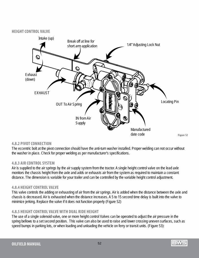
HEIGHT CONTROL VALVE
4.8.2 PIVOT CONNECTIONThe eccentric bolt at the pivot connection should have the anti-turn washer installed. Proper welding can not occur without the washer in place. Check for proper welding as per manufacturer’s specifications.
4.8.3 AIR CONTROL SYSTEMAir is supplied to the air springs by the air supply system from the tractor. A single height control valve on the lead axle monitors the chassis height from the axle and adds or exhausts air from the system as required to maintain a constant distance. The dimension is variable for your trailer and can be controlled by the variable height control adjustment.
4.8.4 HEIGHT CONTROL VALVEThis valve controls the adding or exhausting of air from the air springs. Air is added when the distance between the axle and chassis is decreased. Air is exhausted when the distance increases. A 5 to 15 second time delay is built into the valve to minimize jerking. Replace the valve if it does not function properly (Figure 52)
4.8.5 HEIGHT CONTROL VALVE WITH DUAL RIDE HEIGHTThe use of a single solenoid valve, one or more height control Valves can be operated to adjust the air pressure in the spring bellows to a set second position. This valve can also be used to raise and lower crossing uneven surfaces, such as speed bumps in parking lots, or when loading and unloading the vehicle on ferry or transit units. (Figure 53):
Figure 52
1/4” Adjusting Lock Nut
OUT To Air Spring
EXHAUST
IN from Air Supply
Manufactured date code
Locating Pin
Intake (up)Break off at line for short arm application
Exhaust(down)

53OILFIELD MANUAL
AIR DUMP VALVE WITH GAUGE
Figure 54
Figure 53
4.8.6 AIR DUMP VALVEAll air control systems are equipped with a dump valve that allows the operator to exhaust the air from the system in the following situations (Figure 54):
1. Parking trailer. (loaded or unloaded)2. Loading or unloading trailers when supported by the deck supports.
54OILFIELD MANUAL
4.9 BRAKES
4.9.1 PREVENTATIVE MAINTENANCEThe operator, on the basis of past experience and severity of operation, should establish a schedule for the periodic cleaning, adjustment and inspection of brake equipment. Drum and linings are particularly subject to wear.
The air brake system needs to be inspected, cleaned, lubricated and adjusted on a regular basis and each time the hubs are removed.1. BRAKE DRUMSInspect brake drums. Any accumulation of mud, dirt or rust on the drums should be removed. Any broken or cracked drums should be removed from service. Brake drum manufacturers do not recommend re-boring of brake drums because of the reduced strength of refaced drums.
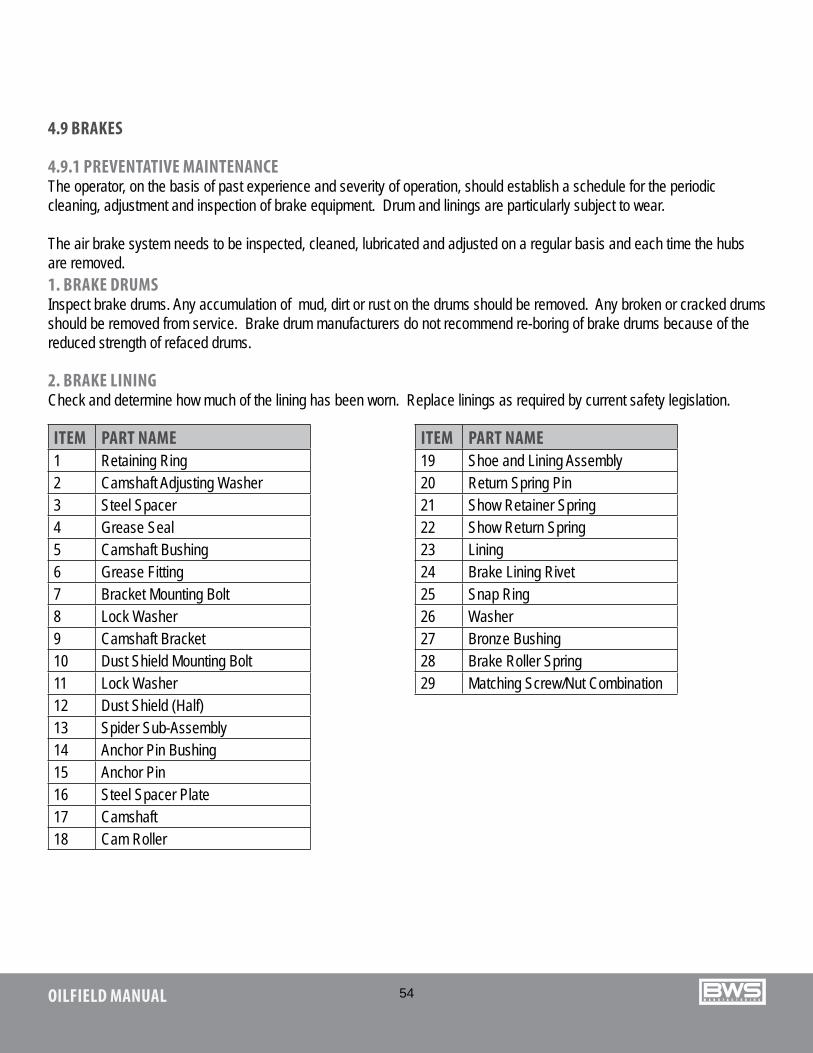
2. BRAKE LININGCheck and determine how much of the lining has been worn. Replace linings as required by current safety legislation.
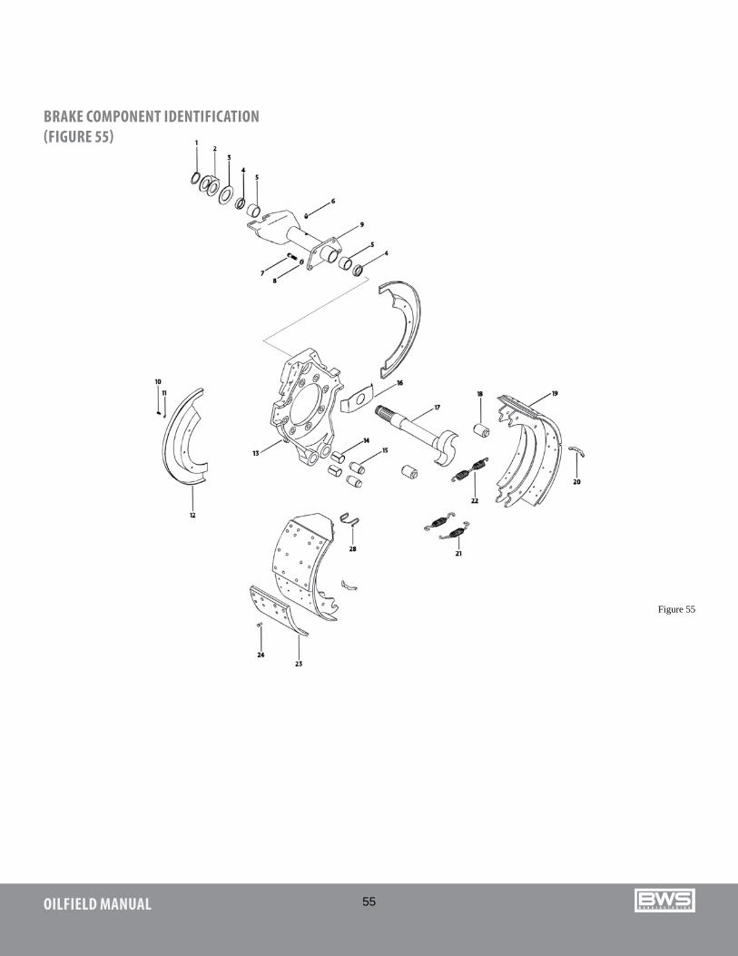
ITEM PART NAME1 Retaining Ring2 Camshaft Adjusting Washer3 Steel Spacer4 Grease Seal5 Camshaft Bushing6 Grease Fitting7 Bracket Mounting Bolt8 Lock Washer9 Camshaft Bracket10 Dust Shield Mounting Bolt11 Lock Washer12 Dust Shield (Half)13 Spider Sub-Assembly14 Anchor Pin Bushing15 Anchor Pin16 Steel Spacer Plate17 Camshaft18 Cam Roller
ITEM PART NAME19 Shoe and Lining Assembly20 Return Spring Pin21 Show Retainer Spring22 Show Return Spring23 Lining24 Brake Lining Rivet25 Snap Ring 26 Washer27 Bronze Bushing28 Brake Roller Spring29 Matching Screw/Nut Combination
55OILFIELD MANUAL
BRAKE COMPONENT IDENTIFICATION (FIGURE 55)
Figure 55

56OILFIELD MANUAL
GUNITE AUTO SLACK ADJUSTER
4.9.2 MAINTENANCE1. BRAKE CHAMBERSYour EZ-2-LOAD Air Detachable is equipped with quick change brakes. These brakes require no maintenance other than if they are leaking they must be replaced. Adjustable brakes maintenance and practices can be obtained from your brake manufacture.2. AUTOMATIC SLACK ADJUSTERSTrailers are equipped with automatic (self-adjusting) slack adjusters. A self-adjusting slack adjuster should never have to be manually adjusted while in service. The only time it should be adjusted is during installation or at re-line. By constantly manually adjusting, the internal clutch life can be shortened. Consult individual manufacturer for proper adjustment procedure. (Figure 56A, 56B & 56C)
HALDEX AUTO SLACK ADJUSTER
Figure 56B
BushingHeat Treated Housing
Direction of Applied Stroke
Workshaft
Coil Spring
‘O’ Ring
Worm Wheel
Clutch Assembly
‘O’ Ring
Adjustment Hex
Enclosed RackInstallation Indicator
Clearance Notch Control Arm
Fixed PointFigure 56C
Figure 56A
Free Stroke = B minus AApplied Stroke = C minus A
A(fully retracted)
B(drum contact using a lever)
C(brake application at
90-100 psi reservoir pressure)
SLACK ADJUSTER SCHEMATIC

57OILFIELD MANUAL
4.10 TORQUE SPECIFICATIONS
Subject fasteners must be torqued to the following specifications. ITEM TORQUE
(ft.lbs) (N.m)1. Suspension components see Fig. 37, 39 & 39 page 48/49 page 48/492. WheelsSpoke wheels 5/8” wheel nuts 3/4” wheel nutsStud-piloted wheels Inner nut (3/4 x 16) Outer nut (1-1/8 x 16)Hub-piloted wheels 8 Stud 10 Stud
160-200190-210
450-500450-500
450-500450-500
215-270255-285
610-680610-680
610-680610-680
3. Wheel bearing nuts Torque inner nut while rotating wheel clockwise Back off inner nut and retorque Back off inner nut1/8 to 1/4 turn (app. 0.003”). Install perforated washer Torque outer nut
200100
250-300
270135
340-4104. Spring brake chamber mounting nuts 80-120 110-1605. Hub cap screws 15-20 20-30
4.11 TIRES
4.11.1 TIRE CARE AND MAINTENANCEAlthough seemingly not requiring instruction, it has been established that through neglect, tires wear fast or fail early, even with the best of maintenance and service that tires deliver.
4.11.2 TIRE INSPECTIONA regular inspection of the tires is the first step in increasing tire mileage. These inspections will help to identify troubles, such as under-inflation, over-inflation and improper alignment. Minor damages, that may be repaired, can be detected during these inspections and save a tire that would otherwise fail.
Inflate tires to manufacturers recommended pressures. Proper inflation costs nothing, but will increase tire mileage. Under-inflation causes abnormal wear at the sides of the tread because the outer edges of the tire carry the load, while the center tends to flex up away from the road. This causes the tire to run hotter.
Tires found to be under-inflated before operation should be returned to the proper pressure.
58OILFIELD MANUAL
Over-inflation causes abnormal wear at the center of the tread, also shortening the life of the tire. This is caused because the center of the tire tread carries more than its share of the load.
Check for correct pressure when tires are cool. When a tire is in use and becomes heated, the air in the tire expands and the air pressure increases. Normal pressure build up is 20 pounds or less. Never bleed the tire to relieve built up pressure. If excessive build up of pressure occurs, load distribution, under-inflation, speed or any combination of these is responsible.
Over-inflation reduces the ability of the tire to absorb ordinary shock and causes fabric or tread separation, or both, resulting in tire failures. It will not compensate for overloading. An over-inflated tire is more vulnerable to snags, cuts and punctures.
4.11.3 MECHANICAL IRREGULARITIESMechanical irregularities that will cause excessive wear include a sprung or sagging axle, which will cause the inside dual tire to carry a greater load.
Brakes that are out of adjustment, or out-of-round brake drums will contribute to rapid and spotty tire wear. Improper brake adjustments will lead to spotty tire wear in several places, while out-of-round drums usually wear in a single spot. Improperly adjusted or worn wheel bearings can lead to uneven tire wear. Also improper axle alignment and worn torque rods will cause excessive tire wear.
4.11.4 RADIAL TIRE APPLICATIONRadial and bias-ply tires should never be “mixed” either in dual combination or on the same axle except in an emergency situation. “Mixing” on the same dual combination will result in uneven wear because of different flexing characteristics.
4.11.5 MATCHING TIRES TO RIMSWhen mounting tires on rims, be sure the right tires are used on the right rims. Many tire failures can be traced to not having matched the tires properly. In most cases there is a preferred and an alternate rim for the popular tire sizes. The preferred widths are recommended as they provide the optimum rim for the tire ratio. Refer to manufacturer’s recommendations.
The tires of each wheel must be matched to within 1/8” of the same rolling radius (3/4” of the same rolling circumference) under normal loading conditions. The tires should have equal pressures.
4.11.6 TIRE WEAR PATTERNS OVER-INFLATION: Excessive wear at the center of the tire indicates the air pressure in the tire is consistently too high. The tire is riding on the center tread and wearing it prematurely. Occasionally, this wear pattern can result from extremely wide tires on narrow rims. To correct, replace either the tires or the wheels.
UNDER-INFLATION: This type of wear usually results from consistent under-inflation. When a tire is under-inflated, there is too much contact with the road by the outer treads, which wear prematurely. When this type of wear occurs and the tire pressure is known to be consistently correct, the need for axle alignment could be indicated.
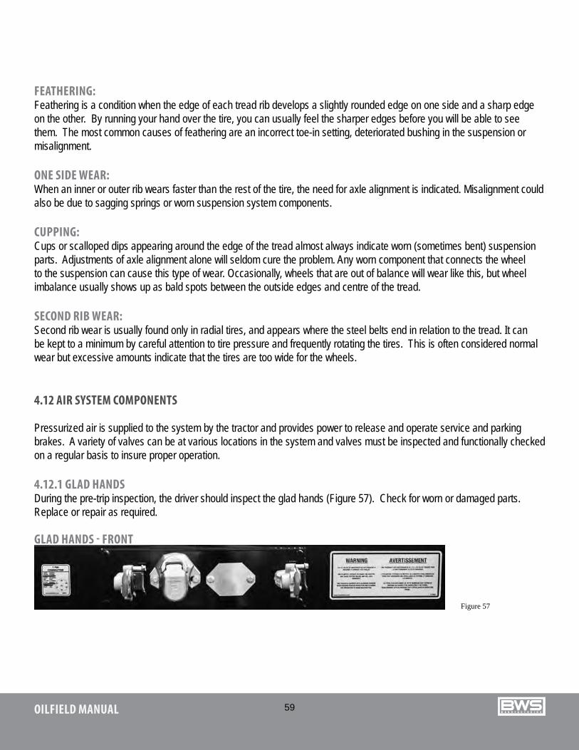
59OILFIELD MANUAL
FEATHERING: Feathering is a condition when the edge of each tread rib develops a slightly rounded edge on one side and a sharp edge on the other. By running your hand over the tire, you can usually feel the sharper edges before you will be able to see them. The most common causes of feathering are an incorrect toe-in setting, deteriorated bushing in the suspension or misalignment.
ONE SIDE WEAR: When an inner or outer rib wears faster than the rest of the tire, the need for axle alignment is indicated. Misalignment could also be due to sagging springs or worn suspension system components.
CUPPING: Cups or scalloped dips appearing around the edge of the tread almost always indicate worn (sometimes bent) suspension parts. Adjustments of axle alignment alone will seldom cure the problem. Any worn component that connects the wheel to the suspension can cause this type of wear. Occasionally, wheels that are out of balance will wear like this, but wheel imbalance usually shows up as bald spots between the outside edges and centre of the tread.
SECOND RIB WEAR: Second rib wear is usually found only in radial tires, and appears where the steel belts end in relation to the tread. It can be kept to a minimum by careful attention to tire pressure and frequently rotating the tires. This is often considered normal wear but excessive amounts indicate that the tires are too wide for the wheels.
4.12 AIR SYSTEM COMPONENTS
Pressurized air is supplied to the system by the tractor and provides power to release and operate service and parking brakes. A variety of valves can be at various locations in the system and valves must be inspected and functionally checked on a regular basis to insure proper operation.
4.12.1 GLAD HANDSDuring the pre-trip inspection, the driver should inspect the glad hands (Figure 57). Check for worn or damaged parts. Replace or repair as required.
GLAD HANDS - FRONT
Figure 57
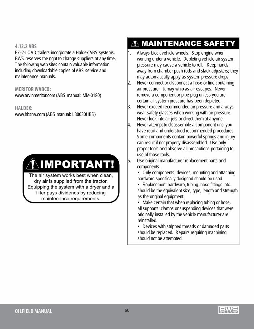
60OILFIELD MANUAL
4.12.2 ABSEZ-2-LOAD trailers incorporate a Haldex ABS systems. BWS reserves the right to change suppliers at any time. The following web sites contain valuable information including downloadable copies of ABS service and maintenance manuals.
MERITOR WABCO:www.arvinmeritor.com (ABS manual: MM-0180)
HALDEX:www.hbsna.com (ABS manual: L30030HBS)
1. Always block vehicle wheels. Stop engine when working under a vehicle. Depleting vehicle air system pressure may cause a vehicle to roll. Keep hands away from chamber push rods and slack adjusters; they may automatically apply as system pressure drops.
2. Never connect or disconnect a hose or line containing air pressure. It may whip as air escapes. Never remove a component or pipe plug unless you are certain all system pressure has been depleted.
3. Never exceed recommended air pressure and always wear safety glasses when working with air pressure. Never look into air jets or direct them at anyone.
4. Never attempt to disassemble a component until you have read and understood recommended procedures. Some components contain powerful springs and injury can result if not properly disassembled. Use only proper tools and observe all precautions pertaining to use of those tools.
5. Use original manufacturer replacement parts and components.• Only components, devices, mounting and attaching hardware specifically designed should be used.• Replacement hardware, tubing, hose fittings, etc. should be the equivalent size, type, length and strength as the original equipment.• Make certain that when replacing tubing or hose, all supports, clamps or suspending devices that were originally installed by the vehicle manufacturer are reinstalled.• Devices with stripped threads or damaged parts should be replaced. Repairs requiring machining should not be attempted.
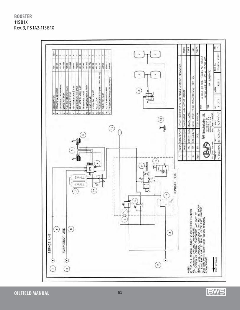
61OILFIELD MANUAL
BOOSTER11SB1XRev. 3, PS1A2-11SB1X
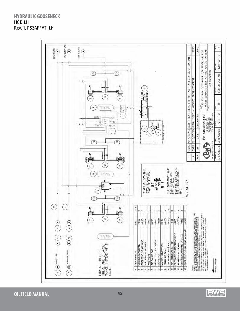
62OILFIELD MANUAL
HYDRAULIC GOOSENECKHGD LHRev. 1, PS3AFFVT_LH

63OILFIELD MANUAL
HYDRAULIC GOOSENECKHDG HHRev. 3, PS3AFFV2T Heavy Haul
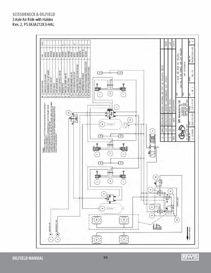
64OILFIELD MANUAL
SCISSORNECK & OILFIELD3 Axle Air Ride with HaldexRev. 2, PS3A3A212X3-HAL
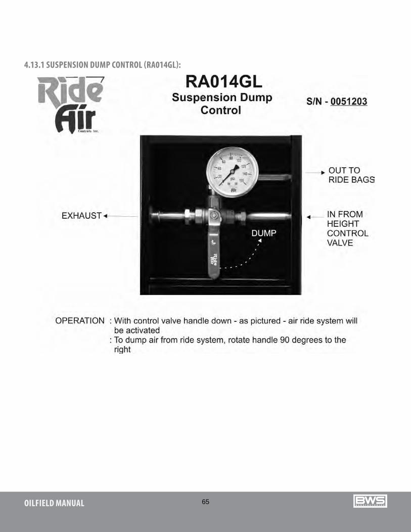
65OILFIELD MANUAL
4.13.1 SUSPENSION DUMP CONTROL (RA014GL):
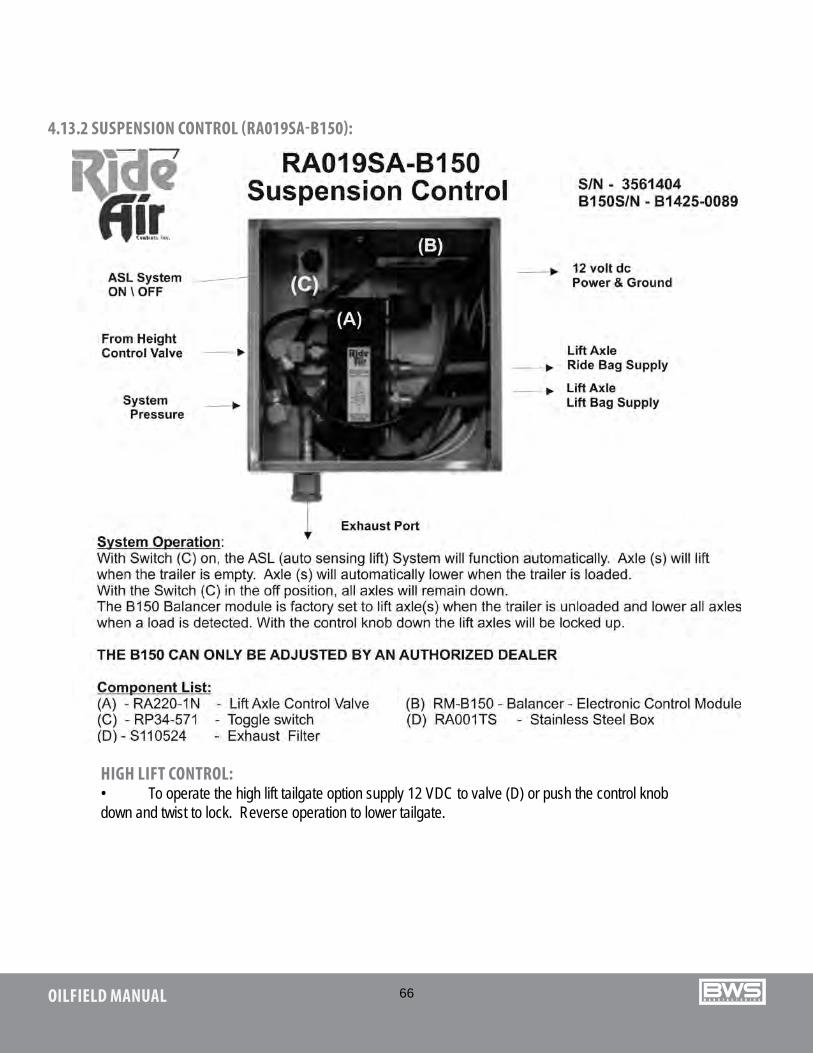
66OILFIELD MANUAL
HIGH LIFT CONTROL:• To operate the high lift tailgate option supply 12 VDC to valve (D) or push the control knob down and twist to lock. Reverse operation to lower tailgate.
4.13.2 SUSPENSION CONTROL (RA019SA-B150):
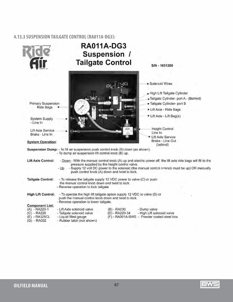
67OILFIELD MANUAL
4.13.3 SUSPENSION TAILGATE CONTROL (RA011A-DG3):
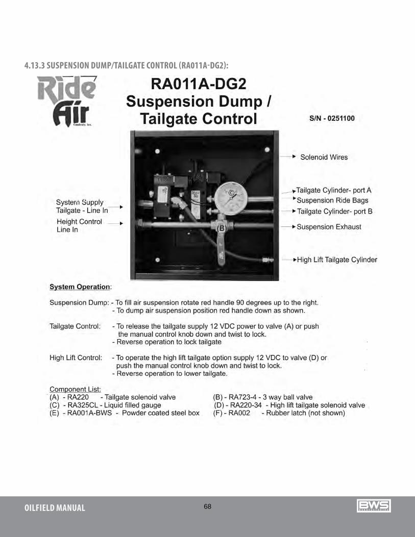
68OILFIELD MANUAL
4.13.3 SUSPENSION DUMP/TAILGATE CONTROL (RA011A-DG2):
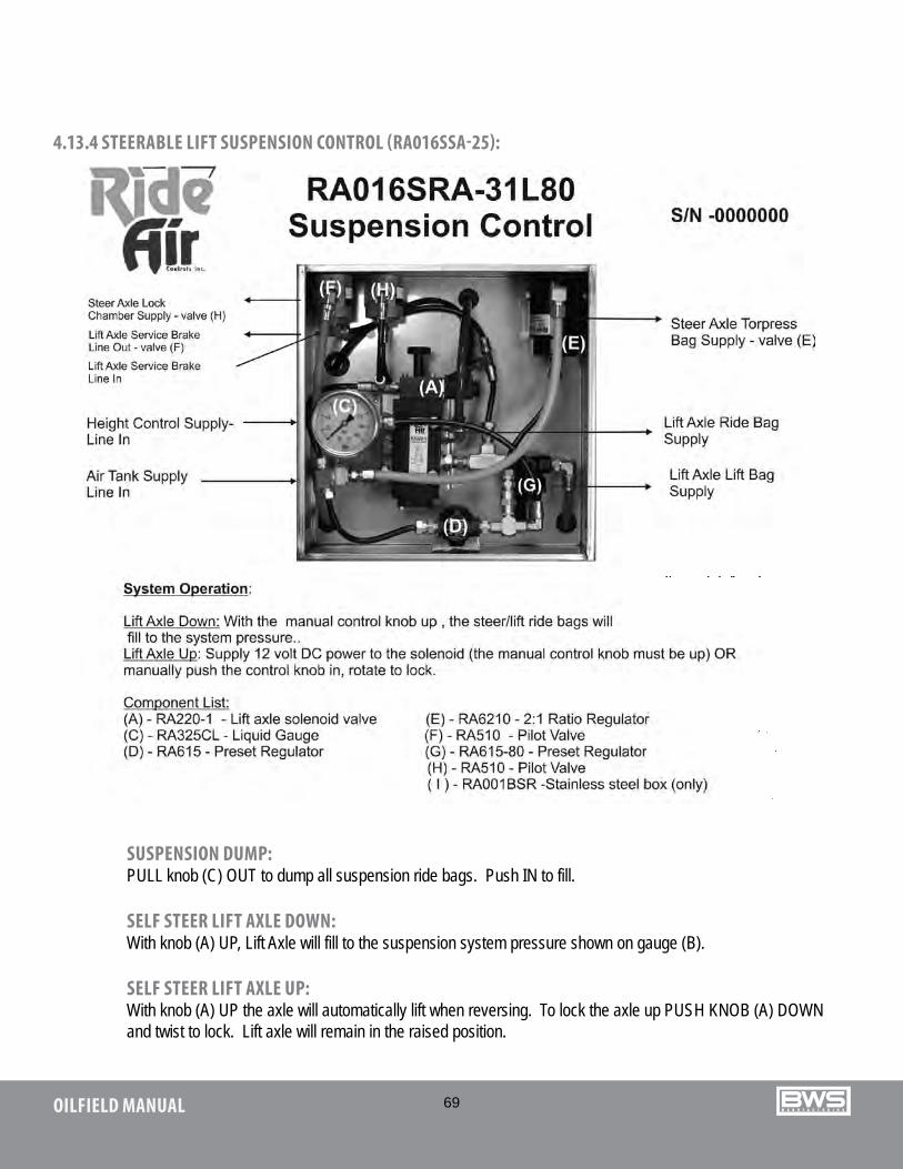
69OILFIELD MANUAL
4.13.4 STEERABLE LIFT SUSPENSION CONTROL (RA016SSA-25):
SUSPENSION DUMP: PULL knob (C) OUT to dump all suspension ride bags. Push IN to fill.
SELF STEER LIFT AXLE DOWN: With knob (A) UP, Lift Axle will fill to the suspension system pressure shown on gauge (B).
SELF STEER LIFT AXLE UP: With knob (A) UP the axle will automatically lift when reversing. To lock the axle up PUSH KNOB (A) DOWN and twist to lock. Lift axle will remain in the raised position.
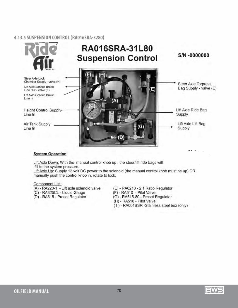
70OILFIELD MANUAL
4.13.5 SUSPENSION CONTROL (RA016SRA-3280)
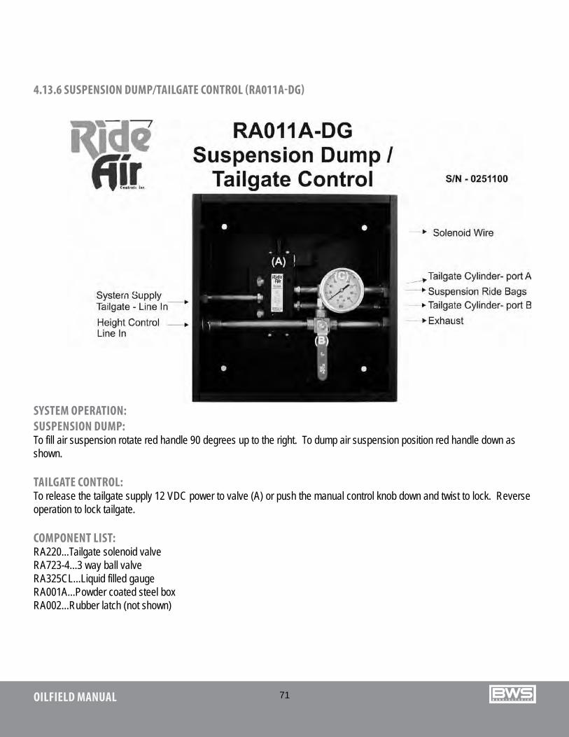
71OILFIELD MANUAL
SYSTEM OPERATION:SUSPENSION DUMP: To fill air suspension rotate red handle 90 degrees up to the right. To dump air suspension position red handle down as shown.
TAILGATE CONTROL: To release the tailgate supply 12 VDC power to valve (A) or push the manual control knob down and twist to lock. Reverse operation to lock tailgate.
COMPONENT LIST:RA220...Tailgate solenoid valveRA723-4...3 way ball valveRA325CL...Liquid filled gaugeRA001A...Powder coated steel boxRA002...Rubber latch (not shown)
4.13.6 SUSPENSION DUMP/TAILGATE CONTROL (RA011A-DG)
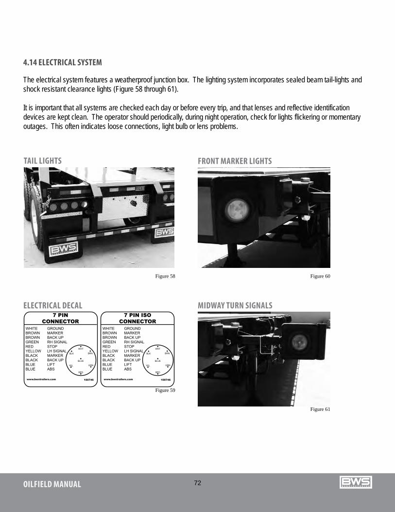
72OILFIELD MANUAL
4.14 ELECTRICAL SYSTEM
The electrical system features a weatherproof junction box. The lighting system incorporates sealed beam tail-lights and shock resistant clearance lights (Figure 58 through 61).
It is important that all systems are checked each day or before every trip, and that lenses and reflective identification devices are kept clean. The operator should periodically, during night operation, check for lights flickering or momentary outages. This often indicates loose connections, light bulb or lens problems.
TAIL LIGHTS FRONT MARKER LIGHTS
MIDWAY TURN SIGNALSELECTRICAL DECAL
Figure 58 Figure 60
Figure 61
Figure 59

73OILFIELD MANUAL
BOOSTER11SB1XRev. 1, WS041

74OILFIELD MANUAL
HYDRAULIC GOOSENECK HDG Rev. 3, WS029

75OILFIELD MANUAL
SCISSORNECK SNRev. 3, WS026

76OILFIELD MANUAL
OILFIELD FLOATOFRev. 1, WS027
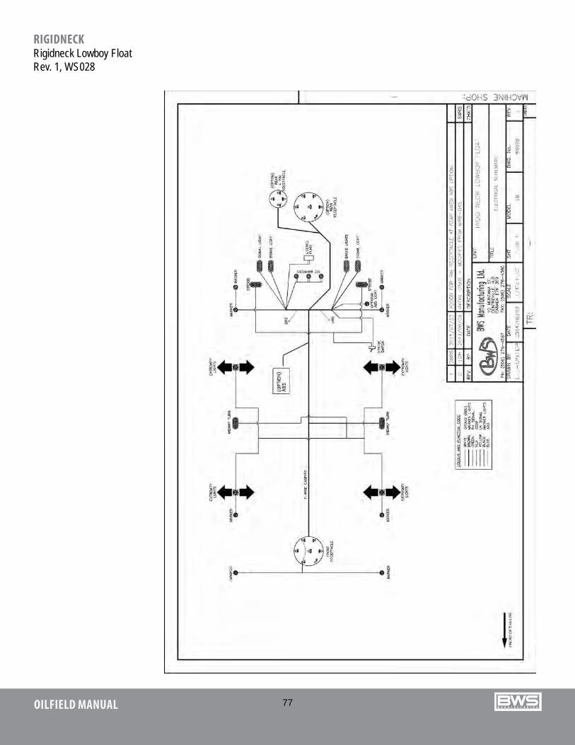
77OILFIELD MANUAL
RIGIDNECKRigidneck Lowboy FloatRev. 1, WS028
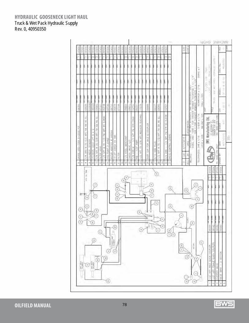
78OILFIELD MANUAL
HYDRAULIC GOOSENECK LIGHT HAULTruck & Wet Pack Hydraulic SupplyRev. 0, 40950350
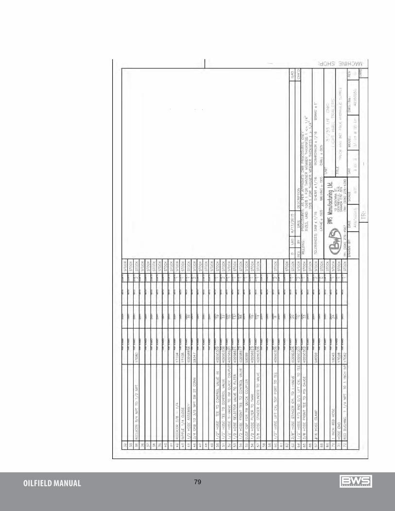
79OILFIELD MANUAL
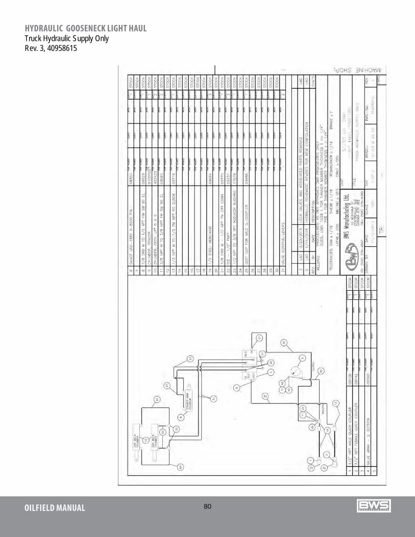
80OILFIELD MANUAL
HYDRAULIC GOOSENECK LIGHT HAULTruck Hydraulic Supply OnlyRev. 3, 40958615
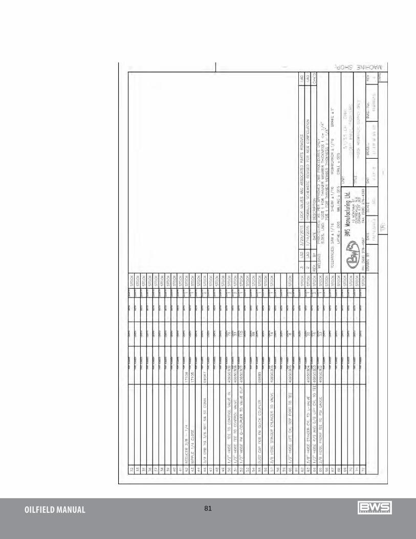
81OILFIELD MANUAL
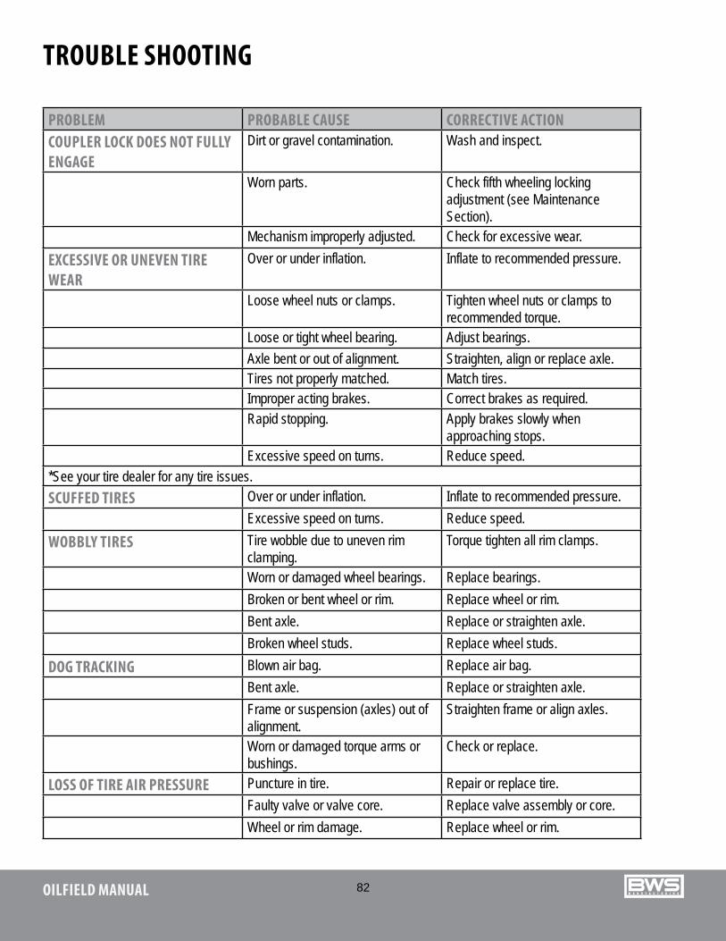
82OILFIELD MANUAL
TROUBLE SHOOTING
PROBLEM PROBABLE CAUSE CORRECTIVE ACTIONCOUPLER LOCK DOES NOT FULLY ENGAGE
Dirt or gravel contamination. Wash and inspect.
Worn parts. Check fifth wheeling locking adjustment (see Maintenance Section).
Mechanism improperly adjusted. Check for excessive wear.EXCESSIVE OR UNEVEN TIRE WEAR
Over or under inflation. Inflate to recommended pressure.
Loose wheel nuts or clamps. Tighten wheel nuts or clamps to recommended torque.
Loose or tight wheel bearing. Adjust bearings.Axle bent or out of alignment. Straighten, align or replace axle.Tires not properly matched. Match tires.Improper acting brakes. Correct brakes as required.Rapid stopping. Apply brakes slowly when
approaching stops.Excessive speed on turns. Reduce speed.
*See your tire dealer for any tire issues.SCUFFED TIRES Over or under inflation. Inflate to recommended pressure.
Excessive speed on turns. Reduce speed.WOBBLY TIRES Tire wobble due to uneven rim
clamping.Torque tighten all rim clamps.
Worn or damaged wheel bearings. Replace bearings.Broken or bent wheel or rim. Replace wheel or rim.Bent axle. Replace or straighten axle.Broken wheel studs. Replace wheel studs.
DOG TRACKING Blown air bag. Replace air bag.Bent axle. Replace or straighten axle.Frame or suspension (axles) out of alignment.
Straighten frame or align axles.
Worn or damaged torque arms or bushings.
Check or replace.
LOSS OF TIRE AIR PRESSURE Puncture in tire. Repair or replace tire.Faulty valve or valve core. Replace valve assembly or core.Wheel or rim damage. Replace wheel or rim.
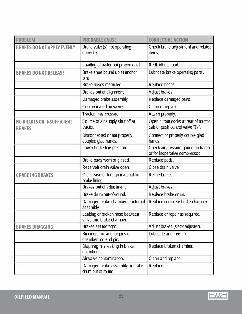
83OILFIELD MANUAL
PROBLEM PROBABLE CAUSE CORRECTIVE ACTIONBRAKES DO NOT APPLY EVENLY Brake valve(s) not operating
correctly.Check brake adjustment and related items.
Loading of trailer not proportional. Redistribute load.BRAKES DO NOT RELEASE Brake shoe bound up at anchor
pins.Lubricate brake operating parts.
Brake hoses restricted. Replace hoses.Brakes out of alignment. Adjust brakes.Damaged brake assembly. Replace damaged parts.Contaminated air valves. Clean or replace.Tractor lines crossed. Attach properly.
NO BRAKES OR INSUFFICIENT BRAKES
Source of air supply shut off at tractor.
Open cutout cocks at rear of tractor cab or push control valve “IN”.
Disconnected or not properly coupled glad hands.
Connect or properly couple glad hands.
Lower brake line pressure. Check air pressure gauge on tractor or for inoperative compressor.
Brake pads worn or glazed. Replace pads.Reservoir drain valve open. Close drain valve.
GRABBING BRAKES Oil, grease or foreign material on brake lining.
Reline brakes.
Brakes out of adjustment. Adjust brakes.Brake drum out-of-round. Replace brake drum.Damaged brake chamber or internal assembly.
Replace complete brake chamber.
Leaking or broken hose between valve and brake chamber.
Replace or repair as required.
BRAKES DRAGGING Brakes set too tight. Adjust brakes (slack adjuster).Binding cam, anchor pins or chamber rod end pin.
Lubricate and free up.
Diaphragm is leaking in brake chamber.
Replace broken chamber.
Air valve contamination. Clean and replace.Damaged brake assembly or brake drum out of round.
Replace.
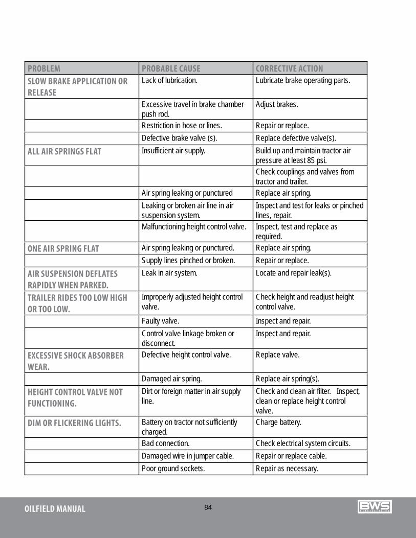
84OILFIELD MANUAL
PROBLEM PROBABLE CAUSE CORRECTIVE ACTIONSLOW BRAKE APPLICATION OR RELEASE
Lack of lubrication. Lubricate brake operating parts.
Excessive travel in brake chamber push rod.
Adjust brakes.
Restriction in hose or lines. Repair or replace.Defective brake valve (s). Replace defective valve(s).
ALL AIR SPRINGS FLAT Insufficient air supply. Build up and maintain tractor airpressure at least 85 psi.Check couplings and valves from tractor and trailer.
Air spring leaking or punctured Replace air spring.Leaking or broken air line in air suspension system.
Inspect and test for leaks or pinched lines, repair.
Malfunctioning height control valve. Inspect, test and replace as required.
ONE AIR SPRING FLAT Air spring leaking or punctured. Replace air spring.Supply lines pinched or broken. Repair or replace.
AIR SUSPENSION DEFLATES RAPIDLY WHEN PARKED.
Leak in air system. Locate and repair leak(s).
TRAILER RIDES TOO LOW HIGH OR TOO LOW.
Improperly adjusted height control valve.
Check height and readjust heightcontrol valve.
Faulty valve. Inspect and repair.Control valve linkage broken or disconnect.
Inspect and repair.
EXCESSIVE SHOCK ABSORBER WEAR.
Defective height control valve. Replace valve.
Damaged air spring. Replace air spring(s).HEIGHT CONTROL VALVE NOT FUNCTIONING.
Dirt or foreign matter in air supply line.
Check and clean air filter. Inspect, clean or replace height control valve.
DIM OR FLICKERING LIGHTS. Battery on tractor not sufficiently charged.
Charge battery.
Bad connection. Check electrical system circuits.Damaged wire in jumper cable. Repair or replace cable.Poor ground sockets. Repair as necessary.
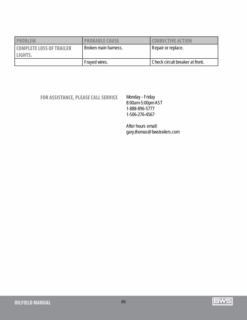
85OILFIELD MANUAL
PROBLEM PROBABLE CAUSE CORRECTIVE ACTIONCOMPLETE LOSS OF TRAILER LIGHTS.
Broken main harness. Repair or replace.
Frayed wires. Check circuit breaker at front.
FOR ASSISTANCE, PLEASE CALL SERVICE Monday - Friday 8:00am-5:00pm AST1-888-896-5777 1-506-276-4567
After hours email:[email protected]
86OILFIELD MANUAL
WARRANTY
BWS Manufacturing Ltd. - Warranty Procedures 2014
STRUCTURAL & COMPONENT WARRANTIES
Is free from defects in material and workmanship. No warranty what-so-ever on tires or ABS Sensor Alignment.
1 year ‘bumper-to-bumper’ - 100% Parts and Labour (from the In Service Date)
For more information, contact the nearest BWS Manufacturing Ltd. authorized dealer or visit www.bwstrailers.com
BWS CONTACT INFORMATION 29 Hawkins Road, Centreville, NB E7K 1A4 Phone (506) 276-4567 Email [email protected]

87OILFIELD MANUAL

and reliable, just l ike you.
www.bwstrailers.com toll free 888.896.5777 www.facebook.com/BWSmfg