Embed Size (px)
Citation preview

Oil Well Monitoring and Control Based on Wireless Sensor Networks using
Atmega 2560 Controller
R.Barani 1
, Mrs.V.Jeya lakshmi 2
1PG Part Time Student, ECE Department, Anna University, Chennai
2Assistant Professor, ECE Department, Kamaraj College Of Engineering and Technology,
Virudhunagar, Tamilnadu, India
Abstract
Most of the Oil Pumping Units (OPU) are
manually monitored. This existing oil-pumping
systems use a high power-consuming process, is
incapable of OPU’s structural health monitoring.
In this paper, a sensor network based intelligent
control is proposed for power economy and efficient oil well health monitoring. The condition
of the oil storage tanks can be monitored using
sensors like level sensor, temperature sensor and
gas sensor. These sensors are fixed inside the oil
storage tanks. The sensor output is given to a
microcontroller located in each oil well. Based on
the condition of the oil storage tanks, the oil
pumping motor is controlled. The monitored
information about each oil well is wirelessly
transmitted to an administrator located in a remote
location. By this method, multiple oil wells within
the transmission range of the wireless sensor
network used can be monitored and controlled.
1. Introduction
Sensor networks have drawn much attention for
their broad practical applications-investigate
specific sensors and sensor networks for air-craft
structural health and performance monitoring. A
real-time radiological area monitoring sensor
network is developed in for emergency response.
In this paper, a sensor network based intelligent
system is proposed for remote oil well health
monitoring and automatic oil-pumping control. The
motivation of developing this system is that 1) due
to the special nature of oil exploration and oil
drilling, the majority of oil pumping units are
spread over barren hills, mountains and deserts, and
2) the existing oil-pumping systems still adopt
manual control.
Existing manual control systems have three
evident drawbacks: 1) The OPU administrators
have to frequently go to the oilfield to check the
OPU status and collect its health analysis data. For
the sake of the harsh oilfield environment,
especially in the winter when it is chilly and
snowing overspreading the whole oilfield, it is
quite difficult to effectively manage and maintain
all OPU manually. 2) Power consumption for OPU
is huge during the oil-pumping process. Especially
in barren oil wells, power wastage is extremely
high because each oil-pumping is not filled under
such condition and thus oil production greatly
drops even though the OPU pumping stroke
remains high. And 3), since an administrator has to
take charge of a number of oil wells, an OPU
malfunction is difficult to locate and repair in a
reasonable time, which causes an oil production
drop.
To overcome these three disadvantages of the
existing manual control system, a sensor network
based automatic control system is proposed for
OPU management and oil well health monitoring
based on wireless sensor networks using Atmega
2560 Controller.
Monitoring multiple oil wells: The proposed
system consists of three-level sensors:
First level sensors (FLS) – designed with a
temperature sensor, a level sensor and a gas
sensor used for oil well data sensing.
Intelligent sensors (IS) –control head (Atmega
2560 Controller) performs significant
malfunction detection and indication based on the elementary processing of data, such as
short circuit and over current.
Third level sensors (TLS) -PC is used for
receiving data from the control heads
periodically and for monitoring the Oil
Pumping Unit from a remote location using
zigbee.
R Barani et al , International Journal of Computer Science & Communication Networks,Vol 3(6),341-346
341
ISSN:2249-5789

Figure 1. Block diagram of monitoring and
intelligent control
Proposed Methodology:
Setup for a single oil well
Figure 2. Proposed system methodologies
2. System Descriptions
The IS consists of the following three modules:
a central processing unit (CPU) module, a sensing
module, a wireless communication module and a
user interface module.
1) Sensing Module: It consists of temperature
sensor, level sensor and gas sensor for data sensing
from an Oil Pumping Unit. The unit converts all
measurements into electrical signals and then
transports them into its corresponding control
heads.
Ultrasonic sensor
Ultrasonic Sensor is used for Oil level measurement in Oil storage tank. The sensor
is fixed at the top of the tank facing the oil
stored.
Working Voltage : 5V(DC)
Working Current : max 15 ma
Working frequency : 40HZ
Output Signal : 0-5V (Output high when
obstacle in range)
Sentry Angle : max 15 degree
Sentry Distance : 0.02m - 5m
High-accuracy : .01m
Input trigger signal : 10microseconds TTL impulse
Echo signal : output TTL PWL signal
Size : 45*20*15mm
Figure 3 Example of Ultrasonic sensors
Temperature Sensor (LM 35):
Temperature Sensor is fixed inside the oil
storage tank.
It can sense temperature from -40 to 85 degree Celsius.
Figure 4. Example of Temperature sensor
Gas sensor:
High sensitivity to LPG, isobutene, propane.
Small sensitivity to alcohol, smoke.
Fast response.
Stable and long life.
Simple drive circuit
Figure 5. Example of Gas sensor
R Barani et al , International Journal of Computer Science & Communication Networks,Vol 3(6),341-346
342
ISSN:2249-5789
2) CPU Module: The CPU in our system is
ATmega2560 microcontroller. It is a standard AT
mega core CPU make suitable for industrial
control.
Figure 6. ATmega2560 Microcontroller
Microcontroller ATmega2560, Operating
Voltage 5V
Input Voltage (recommended) 7-12V, Input
Voltage (limits) 6-20V
Analog Input Pins 16
Digital I/O Pins 54 (of which 14 provide PWM
output)
DC Current per I/O Pin 40 mA
DC Current for 3.3V Pin 50 mA
Flash Memory 256 KB of which 8 KB used by
boot loader
SRAM 8 KB, EEPROM 4 KB
Clock Speed 16 MHz
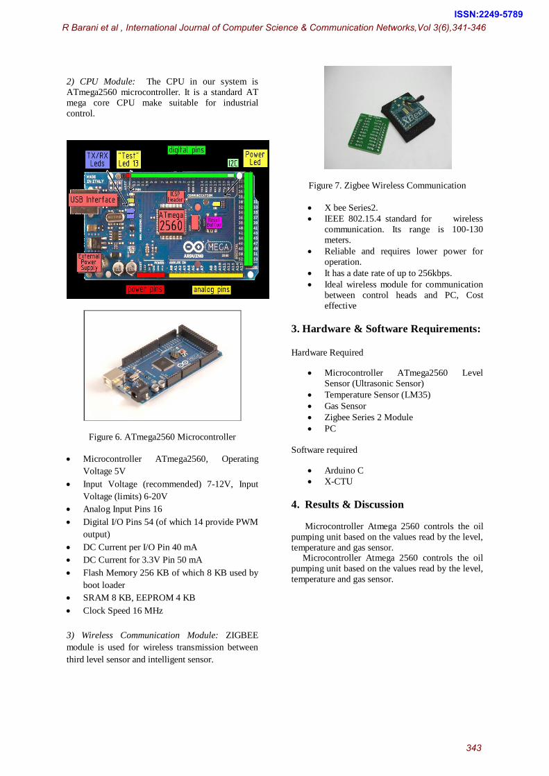
3) Wireless Communication Module: ZIGBEE
module is used for wireless transmission between
third level sensor and intelligent sensor.
Figure 7. Zigbee Wireless Communication
X bee Series2.
IEEE 802.15.4 standard for wireless
communication. Its range is 100-130
meters.
Reliable and requires lower power for
operation.
It has a date rate of up to 256kbps.
Ideal wireless module for communication
between control heads and PC, Cost
effective
3. Hardware & Software Requirements:
Hardware Required
Microcontroller ATmega2560 Level
Sensor (Ultrasonic Sensor)
Temperature Sensor (LM35)
Gas Sensor
Zigbee Series 2 Module
PC
Software required
Arduino C
X-CTU
4. Results & Discussion
Microcontroller Atmega 2560 controls the oil
pumping unit based on the values read by the level,
temperature and gas sensor. Microcontroller Atmega 2560 controls the oil
pumping unit based on the values read by the level,
temperature and gas sensor.
R Barani et al , International Journal of Computer Science & Communication Networks,Vol 3(6),341-346
343
ISSN:2249-5789

Figure 8. Oil well parameter output 1
The normal temperature of the oil storage tank is preset as 50°C. When the output of LM35 goes
above 50°C, the oil pumping motor should be shut
down. When the temperature lies below 50°C, the
oil pumping motor keeps running.
In figure 8, the temperature of oil well is
53.90°C. The oil level is normal, but, the
temperature is above the threshold value. So, the oil
pumping motor of oil well is shut down.
Inside the oil storage tank, the normal
concentration of combustible gas level is 300ppm.
Under normal conditions, the oil pumping motor
keeps running. When the concentration of
combustible gases like natural gas, iso-butane is
high, the gas sensor output is greater than 750ppm
and the oil pumping motor is shut down.
Figure 9. Oil well parameter output 2
In figure 9, the gas sensor output is 807. Since,
the concentration of gas is above the threshold
value, the oil pump is shut down.
Figure 10. Oil well parameter output 3
In Figure 10 shows the working of level sensor
of oil well. The threshold value for level sensor is preset as 5cm. When the level sensor output falls
below 5cm, it shows that the oil storage tank is
almost full and the oil pumping motor should be
shut down. In figure 10, the level sensor output is
3cm and so, the oil pump is shutdown.
Table 1. Tabulation by varying input parameters
OIL WELL SENSORS OUTPUT
S.No
Temperature
(cm)
Level
(cm)
Gas
(ppm)
Motor
Condition
1 35.28 22 262 Runing
2 24.99 23 807 Shutdown
3 35.28 36 802 Shutdown
4 54.39 37 235 Shutdown
5 66.64 37 241 Shutdown
6 34.79 5 274 Shutdown
7 32.34 4 254 Shutdown
8 35.77 15 255 Running
9 35.28 3 255 Shutdown
10 53.90 30 243 Shutdown
R Barani et al , International Journal of Computer Science & Communication Networks,Vol 3(6),341-346
344
ISSN:2249-5789

This table 1 shows the oil parameters
output.These outputs are obtain from
temperatue,level and gas sensors respectively.
Hardware Design Layout:
Figure 11. Top Elevation of Hardware Design
Figure 12. Bottom Elevation of Hardware Design
Figure 13. Atmega 2560 Microcontrollers
Figure 14. Control Circuit of dc Motor
Figure 15. Zigbee series 2 Module & Transmitter
Sensors
In the proposed system, the following sensors are
used which is shown below.
Figure 16. Level Sensor HC-SR04
Figure 17. Temperature Sensor LM35
R Barani et al , International Journal of Computer Science & Communication Networks,Vol 3(6),341-346
345
ISSN:2249-5789

Figure 18. Gas Sensor MQ-6
5) CONCLUSION
A sensor network based oil well remote health
monitoring and intelligent control system was
developed for Oil Pumping Unit management in
the oilfield. This system consists of level sensor,
temperature sensor and gas sensor for sensing the
condition of the oil storage tank. The control head
processes the sensor output values and controls the
oil pumping motor accordingly. The control head
transmits the condition of each oil well using a Zigbee transmitter. An administrator located in the
Zigbee receiver side can monitor the oil wells using
the X-CTU software and manual monitoring in oil
wells would be avoided. When the oil storage tank
is almost full, the oil pumping motor is shut down
and there is no wastage of power. The condition of
the oil well from a remote location is received at
the zigbee receiver end and can be displayed using
X-CTU software in the range of the wireless sensor
network. In the future, the range of the wireless
sensor network can be increased by increasing the
operating power of the network. When the range of
the wireless sensor network is increases, more
number of oil wells can be monitored from a
remote location and data transfer would occur with
minimum power requirement.
6) REFERENCES
[1] C. Cheng, C. Tse, and F. Lau, “A delay-aware
data collection network structure for wireless
sensor networks,” IEEE Sensors J., vol.11,
no.1,Apr. 2011
[2] C. Cheng, C. Tse,and F. Lau, “A clustering
algorithm for wireless sensor networks based
on social insect colonies,” IEEE Sensors
J.,vol.11,no.1,Apr.2011.
[3] M. C. Rodriguez-Sanchez, S. Borromeo, and J.
Hernandez-Tamames, “Wireless sensor
network for conservation and monitoring
cultural assets,” IEEE Sensors J., vol. 11, no.
1, Apr. 2011.
[4] Ren C. Luo, Fellow, IEEE, Chih-Chen Yih,
and Kuo Lan Su “Multi sensor Fusion and
Integration: Approaches, Applications, and
Future Research Directions” IEEE Sensors
Journal, Vol. 2, No. 2, April 2002.
[5] D. G. Senesky, B. Jamshidi, K. Cheng, and A.
P. Pisano, “Harsh environment silicon carbide
sensors for health and performance monitoring
of aerospace systems: A review,” IEEE
Sensors J., vol. 9, no. 11, pp. 1472–1478, Nov.
2009.
[6] Q. Ling, Z. Tian, Y. Yin, and Y. Li, “Localized
structural health monitoring using energy-
efficient wireless sensor networks,” IEEE
Sensor J., vol. 9, no. 11, pp. 1596–1604, Nov.
2009.
[7] Ying-Wen Bai, Li-Sih Shen and Zong-Han Li
“Design and Implementation of an Embedded
Home Surveillance System by Use of Multiple
Ultrasonic Sensors”IEEE Transactions on
Consumer Electronics, Vol. 56, No. 1, Feb.
R Barani et al , International Journal of Computer Science & Communication Networks,Vol 3(6),341-346
346
ISSN:2249-5789