Embed Size (px)
Citation preview

OIL REFINERY PROCESSES
Developed for:
International Refinery Consultants, Inc.
And
By: Joseph D. Fournier: B.Sc.E.E., M.Sc.E.E
OUTLINE
Introduction
Physical Processes
Thermal Processes
Catalytic Processes
Conversion of Heavy Residues
Treatment of Refinery Gas Streams
2
INTRODUCTION
Oil refining is a key activity in the CPI.
Over 600 refineries worldwide have a total annual capacity of more than 3500 x 106
tonnes.
Goal of oil refining is twofold:i. production of fuels for transportation, power
generation and heating; and
ii. production of raw materials for the CPI.
Oil refineries are complex plants but are relatively mature and highly integrated.
3
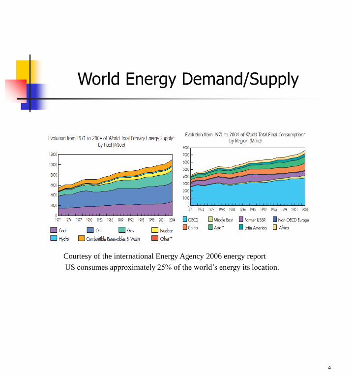
World Energy Demand/Supply
4
US consumes approximately 25% of the world’s energy its location.
Courtesy of the international Energy Agency 2006 energy report
5
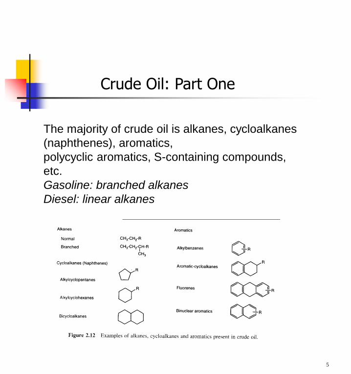
The majority of crude oil is alkanes, cycloalkanes
(naphthenes), aromatics,
polycyclic aromatics, S-containing compounds,
etc.
Gasoline: branched alkanes
Diesel: linear alkanes
Crude Oil: Part One
6
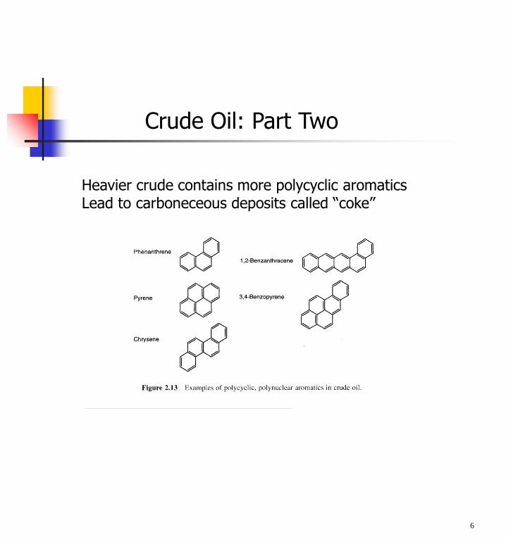
Heavier crude contains more polycyclic aromaticsLead to carboneceous deposits called “coke”
Crude Oil: Part Two
7
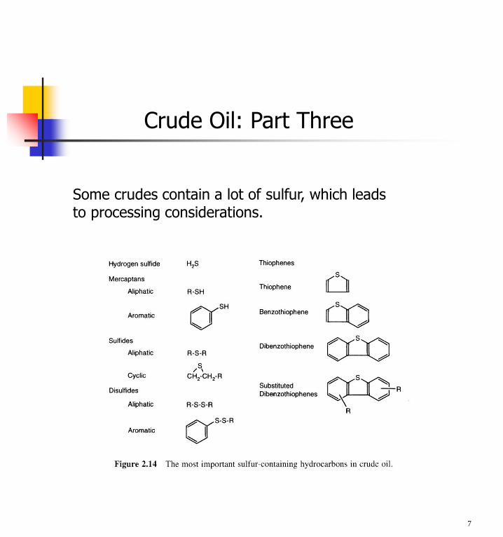
Some crudes contain a lot of sulfur, which leadsto processing considerations.
Crude Oil: Part Three
Refining operations: One
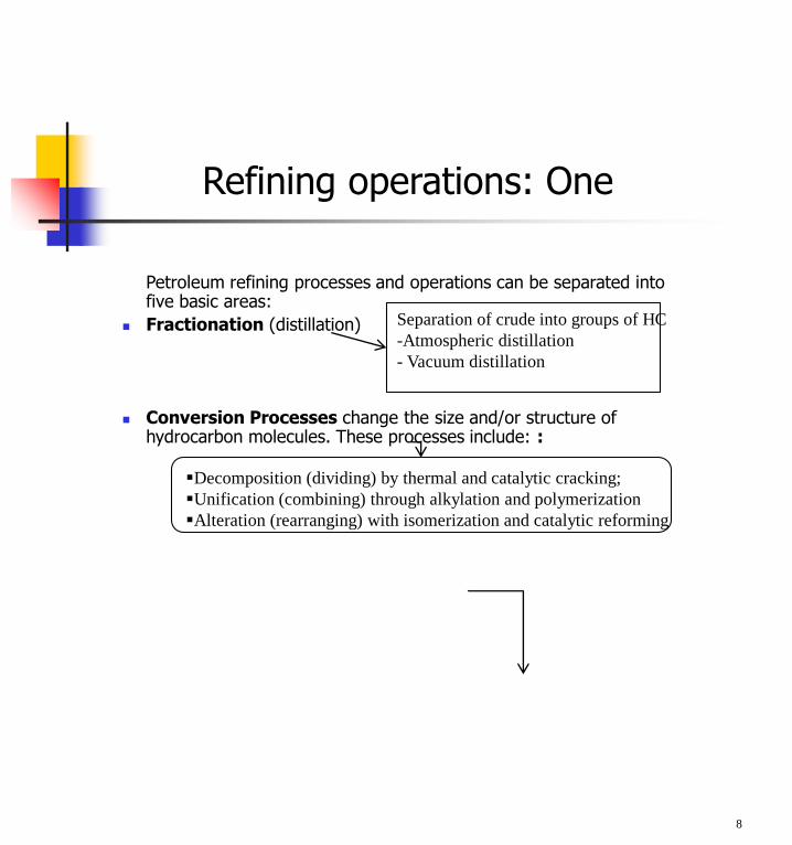
Petroleum refining processes and operations can be separated into five basic areas:
Fractionation (distillation)
Conversion Processes change the size and/or structure of hydrocarbon molecules. These processes include: :
8
Separation of crude into groups of HC
-Atmospheric distillation
- Vacuum distillation
Decomposition (dividing) by thermal and catalytic cracking;
Unification (combining) through alkylation and polymerization
Alteration (rearranging) with isomerization and catalytic reforming
9
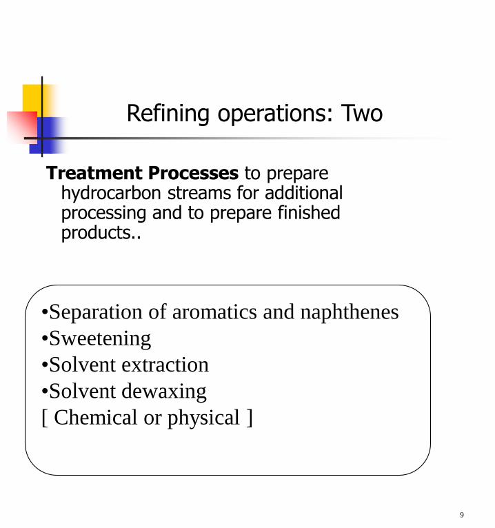
•Separation of aromatics and naphthenes
•Sweetening
•Solvent extraction
•Solvent dewaxing
[ Chemical or physical ]
Refining operations: Two
Treatment Processes to prepare hydrocarbon streams for additional processing and to prepare finished products..
Formulating and Blending is the process of mixing and combining hydrocarbon fractions, additives, and other components to produce finished products with specific performance properties.
Other Refining Operations include: light-ends recovery; sour-water stripping; solid waste, process-water and wastewater treatment; cooling, storage and handling and product movement; hydrogen production; acid and tail-gas treatment; and sulfur recovery.
10
Refining operations: Three
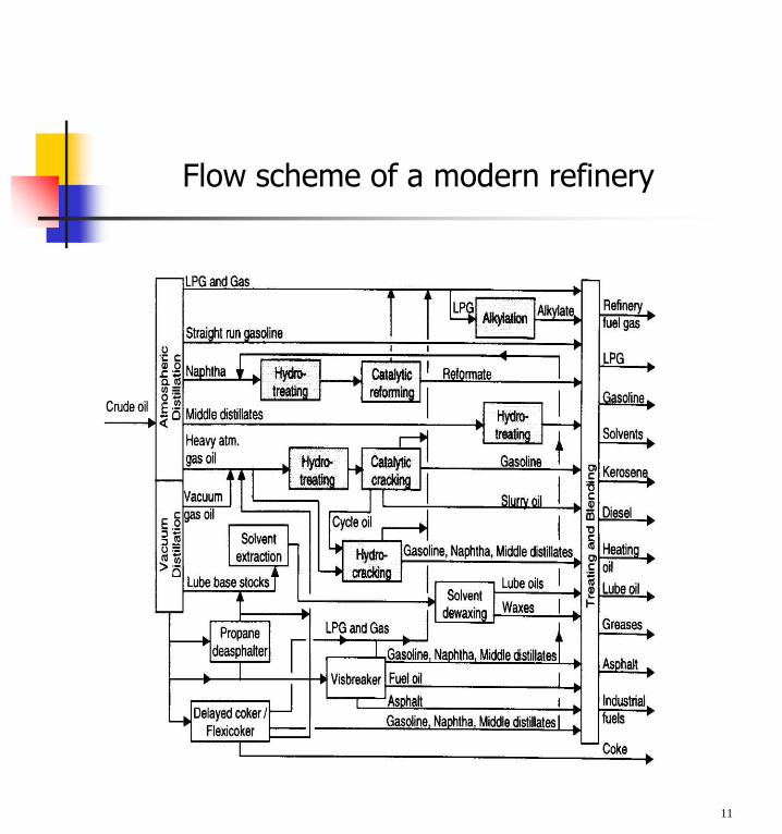
Flow scheme of a modern refinery
11
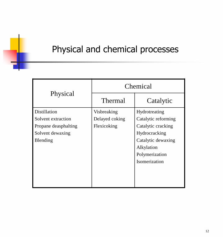
Physical and chemical processes
12
PhysicalChemical
Thermal Catalytic
Distillation
Solvent extraction
Propane deasphalting
Solvent dewaxing
Blending
Visbreaking
Delayed coking
Flexicoking
Hydrotreating
Catalytic reforming
Catalytic cracking
Hydrocracking
Catalytic dewaxing
Alkylation
Polymerization
Isomerization
PHYSICAL PROCESSES
Desalting/dehydration
Crude distillation
Propane deasphalting
Solvent extraction and dewaxing
Blending
13
Desalting/dehydration: One
Crude oil often contains water, inorganic salts, suspended solids, and water-soluble trace metals.
Step 0ne in the refining process is to remove these contaminants so as to reduce corrosion, plugging, and fouling of equipment and to prevent poisoning catalysts in processing units.
The two most typical methods of crude-oil desalting are chemical and electrostatic separation, and both use hot water as the extraction agent.
In chemical desalting, water and chemical surfactant(demulsifiers) are added to the crude, which is heated so that salts and other impurities dissolve or attach to the water, then held in a tank to settle out.
Electrical desalting is the application of high-voltage electrostatic charges to concentrate suspended water globules in the bottom of the settling tank. Surfactants are added only when the crude has a large amount of suspended solids.
A third (and rare) process filters hot crude using diatomaceous earth.
14

The crude oil feedstock is heated to 65-180°C to
reduce viscosity and surface tension for easier mixing and separation of the water. The temperature is limited by the vapor pressure of the crude-oil feedstock.
In both methods other chemicals may be added. Ammonia is often used to reduce corrosion. Caustic or acid may be added to adjust the pH of the water wash.
15
Desalting/dehydration: Two
16
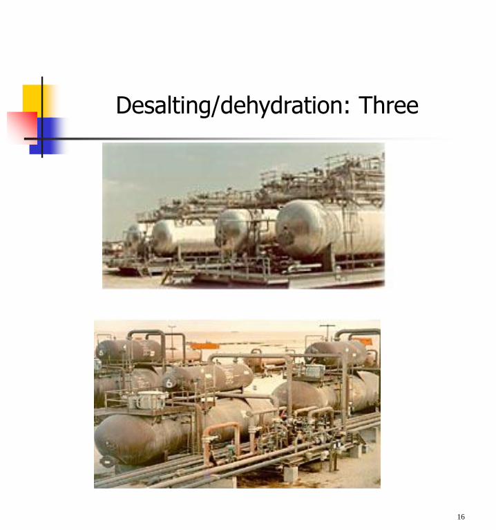
Desalting/dehydration: Three
Continuous distillation columns
Classified according to:
1. Nature of the feed that they are processing:
binary column - feed contains only two components;
multi-component column - feed contains more than two components.
2. Number of product streams they have:
multi-product column - column has more than two product streams.
3. Where extra feed exits when used to help with the separation:
extractive distillation - where the extra feed appears in the bottom product stream;
azeotropic distillation - where the extra feed appears at the top product stream.
4. Type of column internals:
tray column - trays of various designs used to hold up the liquid to provide better contact between vapour and liquid;
packed column - packings are used to enhance vapour-liquid contact.
17
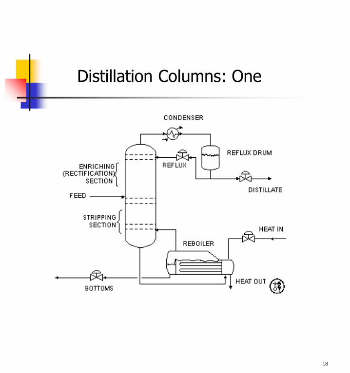
Distillation Columns: One
18

Distillation Columns: Two
A vertical shell where separation of liquid components is done.
Column internals e.g.trays/plates and/or packingswhich are used to enhance component separations.
A reboiler to provide the necessary vaporization for the distillation process.
A condenser to cool and condense the vapourleaving the top of the column.
A reflux drum to hold the condensed vapour from the top of the column so that liquid (reflux) can be recycled back to the column.
19
Trays and plates: One
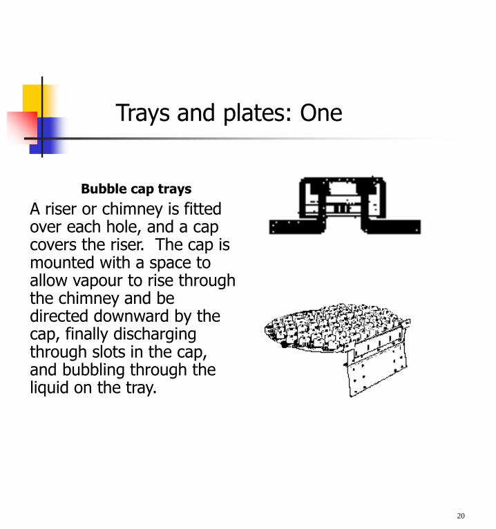
Bubble cap trays
A riser or chimney is fitted over each hole, and a cap covers the riser. The cap is mounted with a space to allow vapour to rise through the chimney and be directed downward by the cap, finally discharging through slots in the cap, and bubbling through the liquid on the tray.
20
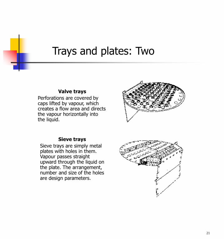
Valve trays
Perforations are covered by caps lifted by vapour, which creates a flow area and directs the vapour horizontally into the liquid.
Sieve trays
Sieve trays are simply metal plates with holes in them. Vapour passes straight upward through the liquid on the plate. The arrangement, number and size of the holes are design parameters.
21
Trays and plates: Two
Flows in a tray column: One
22
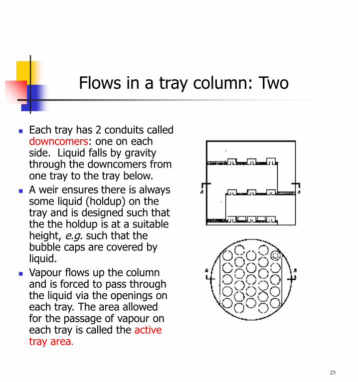
Flows in a tray column: Two
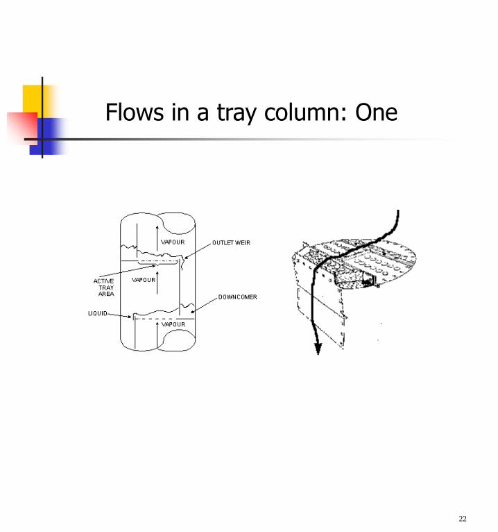
Each tray has 2 conduits called downcomers: one on each side. Liquid falls by gravity through the downcomers from one tray to the tray below.
A weir ensures there is always some liquid (holdup) on the tray and is designed such that the the holdup is at a suitable height, e.g. such that the bubble caps are covered by liquid.
Vapour flows up the column and is forced to pass through the liquid via the openings on each tray. The area allowed for the passage of vapour on each tray is called the active tray area.
23
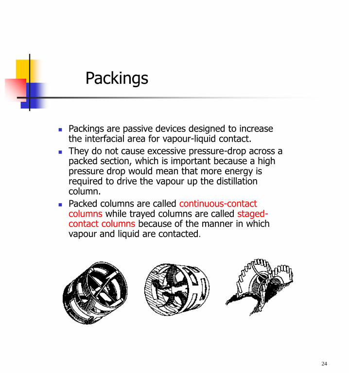
Packings
Packings are passive devices designed to increase the interfacial area for vapour-liquid contact.
They do not cause excessive pressure-drop across a packed section, which is important because a high pressure drop would mean that more energy is required to drive the vapour up the distillation column.
Packed columns are called continuous-contact columns while trayed columns are called staged-contact columns because of the manner in which vapour and liquid are contacted.
24
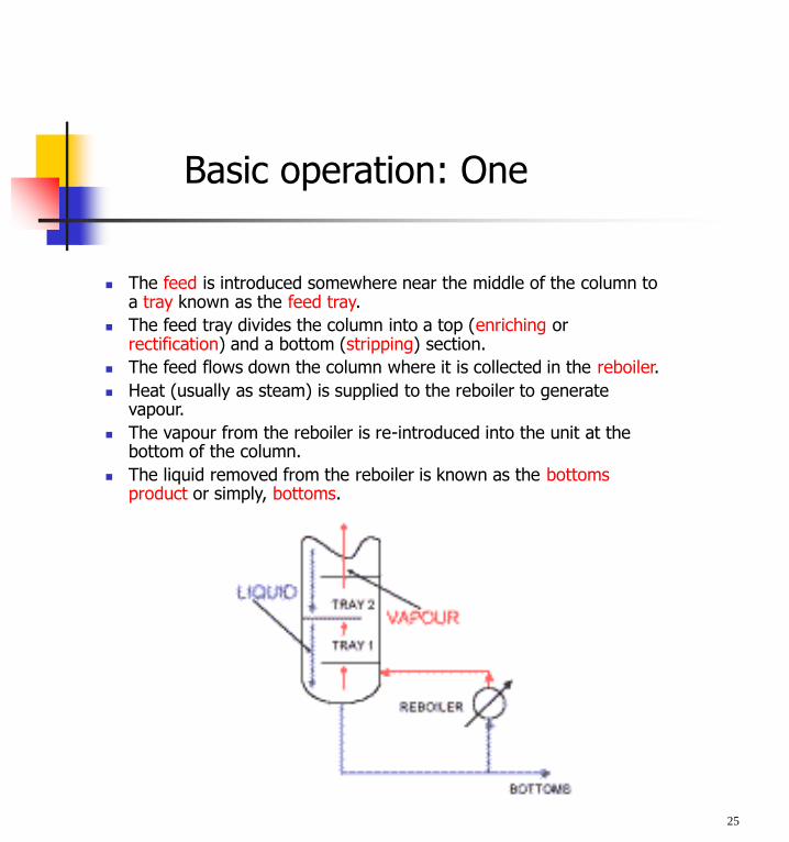
Basic operation: One
The feed is introduced somewhere near the middle of the column to a tray known as the feed tray.
The feed tray divides the column into a top (enriching or rectification) and a bottom (stripping) section.
The feed flows down the column where it is collected in the reboiler.
Heat (usually as steam) is supplied to the reboiler to generate vapour.
The vapour from the reboiler is re-introduced into the unit at the bottom of the column.
The liquid removed from the reboiler is known as the bottoms product or simply, bottoms.
25
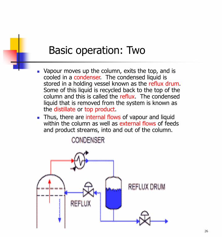
Basic operation: Two
Vapour moves up the column, exits the top, and is cooled in a condenser. The condensed liquid is stored in a holding vessel known as the reflux drum. Some of this liquid is recycled back to the top of the column and this is called the reflux. The condensed liquid that is removed from the system is known as the distillate or top product.
Thus, there are internal flows of vapour and liquid within the column as well as external flows of feeds and product streams, into and out of the column.
26
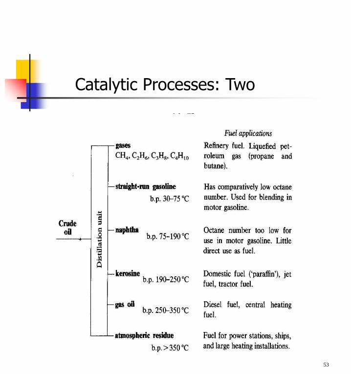
Crude distillation
Step 1 in the refining process is the separation of crude oil into various fractions by distillation in atmospheric and vacuum towers. The main fractions or "cuts" obtained have specific boiling-point ranges and can be classified in order of decreasing volatility into gases, light distillates, middle distillates, gas oils, and residuum.
Atmospheric distillation
The desalted crude feedstock is preheated using recovered process heat. The feedstock then flows to a direct-fired crude charge heater then into the vertical distillation column just above the bottom, at pressures slightly above atmospheric and at temperatures ranging from 340-370°C (above these temperatures undesirable thermal cracking may occur). All but the heaviest fractions flash into vapor.
As the hot vapor rises in the tower, its temperature is reduced. Heavy fuel oil or asphalt residue is taken from the bottom. At successively higher points on the tower, the various major products including lubricating oil, heating oil, kerosene, gasoline, and uncondensed gases (which condense at lower temperatures) are drawn off.
27
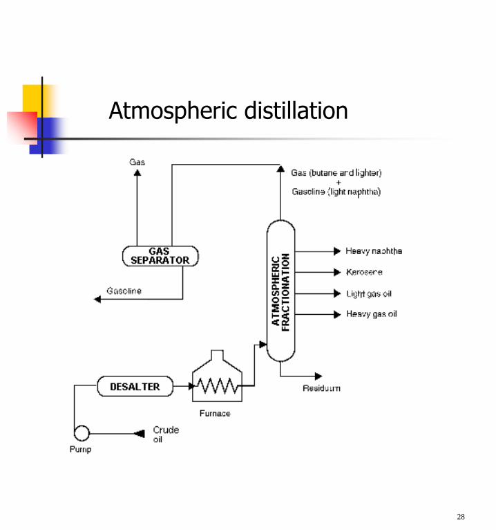
Atmospheric distillation
28
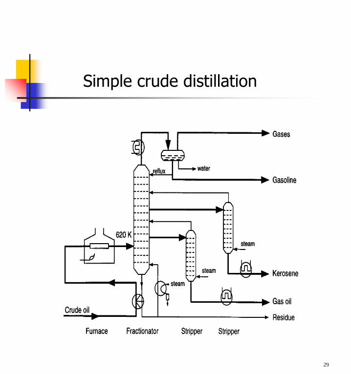
Simple crude distillation
29
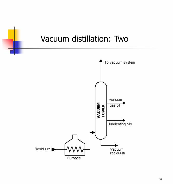
Vacuum distillation: One
To further distill the residuum or topped crude from the atmospheric tower without thermal cracking, reduced pressure is required.
The process takes place in one or more vacuum distillation towers.
The principles of vacuum distillation resemble those of fractional distillation except that larger diameter columns are used to maintain comparable vapor velocities at the reduced pressures. The internal designs of some vacuum towers are different from atmospheric towers in that random packing and demister pads are used instead of trays.
A typical first-phase vacuum tower may produce gas oils, lubricating-oil base stocks, and heavy residual for propane deasphalting.
A second-phase tower operating at lower vacuum may distill surplus residuum from the atmospheric tower, which is not used for lube-stock processing, and surplus residuum from the first vacuum tower not used for deasphalting.
Vacuum towers are typically used to separate catalytic cracking feedstock from surplus residuum.
30
Vacuum distillation: Two
31
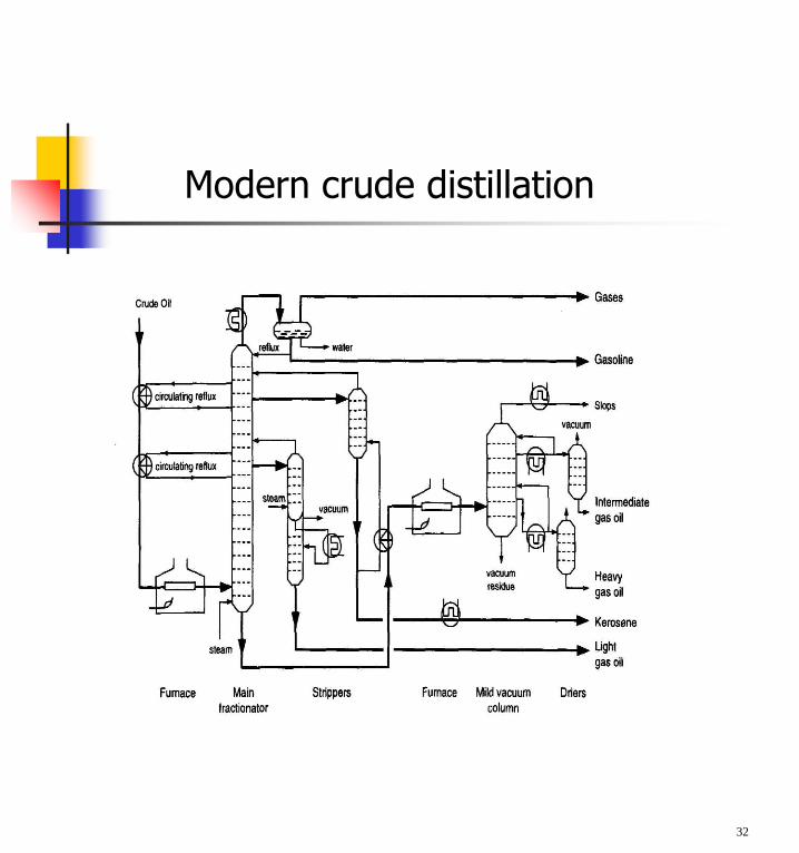
Modern crude distillation
32
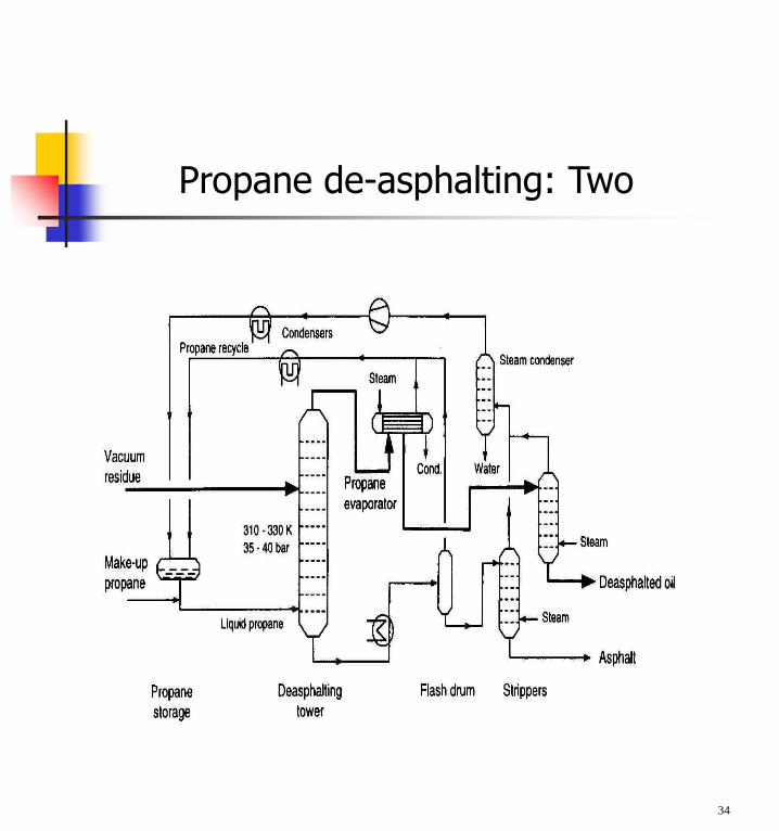
Propane de-asphalting: One
Coke-forming tendencies of heavier distillation products are reduced by removal of asphaltenicmaterials by solvent extraction.
Liquid propane is a good solvent (butane and pentane are also commonly used).
Deasphalting is based on solubility of hydrocarbons in propane, i.e. the type of molecule rather than RMM as in distillation.
Vacuum residue is fed to a countercurrent deasphalting tower. Alkanes dissolve in propane whereas asphaltenic materials (aromaticcompounds), ‘coke-precursors’ do not.
Asphalt is sent for thermal processing.
33
Propane de-asphalting: Two
34
Solvent Treating: One
Solvent treating is a widely used method of refining lubricating oils as well as a host of other refinery stocks.
Since distillation (fractionation) separates petroleum products into groups only by their boiling-point ranges, impurities may remain. These include organic compounds containing sulfur, nitrogen, and oxygen; inorganic salts and dissolved metals; and soluble salts that were present in the crude feedstock.
In addition, kerosene and distillates may have trace amounts of aromatics and naphthenes, and lubricating oil base-stocks may contain wax.
Solvent refining processes including solvent extraction and solvent dewaxing usually remove these undesirables at intermediate refining stages or just before sending the product to storage.
35
The purpose of solvent extraction is to prevent corrosion, protect catalyst in subsequent processes, and improve finished products by removing unsaturated, aromatic hydrocarbons from lubricant and grease stocks.
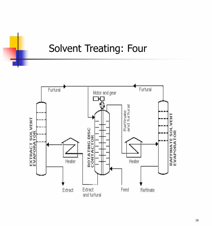
The solvent extraction process separates aromatics, naphthenes, and impurities from the product stream by dissolving or precipitation. The feedstock is first dried and then treated using a continuous countercurrent solvent treatment operation.
In one type of process, the feedstock is washed with a liquid in which the substances to be removed are more soluble than in the desired resultant product. In another process, selected solvents are added to cause impurities to precipitate out of the product. In the adsorption process, highly porous solid materials collect liquid molecules on their surfaces.
The solvent is separated from the product stream by heating, evaporation, or fractionation, and residual trace amounts are subsequently removed from the raffinate by steam stripping or vacuum flashing.
36
Solvent Treating: Two
Electric precipitation may be used for separation of inorganic compounds.
The solvent is regenerated for reused in the process.
The most widely used extraction solvents are phenol, furfural, and cresylic acid.
Other solvents less frequently used are liquid sulfur dioxide, nitrobenzene, and 2,2' dichloroethyl ether.
The selection of specific processes and chemical agents depends on the nature of the feedstock being treated, the contaminants present, and the finished product requirements.
37
Solvent Treating: Three
38
Solvent Treating: Four
Solvent dewaxing is used to remove wax from either distillate or residual basestock at any stage in the refining process.
There are several processes in use for solvent dewaxing, but all have the same general steps, which are:: mixing the feedstock with a solvent; precipitating the wax from the mixture by chilling;
and recovering the solvent from the wax and dewaxed
oil for recycling by distillation and steam stripping.
Usually two solvents are used: toluene, which dissolves the oil and maintains fluidity at low temperatures, and methyl ethyl ketone (MEK), which dissolves little wax at low temperatures and acts as a wax precipitating agent.
Other solvents sometimes used include benzene, methyl isobutyl ketone, propane, petroleum naphtha, ethylene dichloride, methylene chloride, and sulfur dioxide.
In addition, there is a catalytic process used as an alternate to solvent dewaxing.
39
Solvent Dewaxing
40
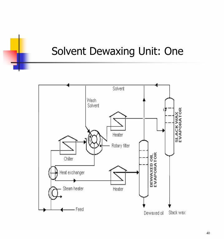
Solvent Dewaxing Unit: One
41
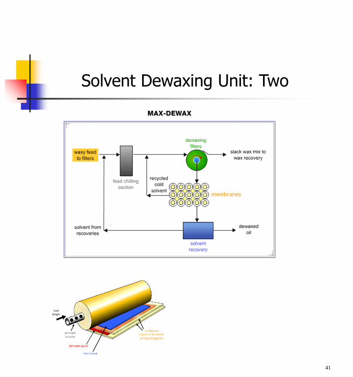
Solvent Dewaxing Unit: Two
Blending
Blending is the physical mixture of a number of different liquid hydrocarbons to produce a finished product with certain desired characteristics.
Products can be blended in-line through a manifold system, or batch blended in tanks and vessels.
In-line blending of gasoline, distillates, jet fuel, and kerosene is accomplished by injecting proportionate amounts of each component into the main stream where turbulence promotes thorough mixing.
Additives including octane enhancers, anti-oxidants, anti-knock agents, gum and rust inhibitors, detergents, etc. are added during and/or after blending to provide specific properties not inherent in hydrocarbons.
42
THERMAL PROCESSES
When a hydrocarbon is heated to a sufficiently high temperature thermal cracking occurs. This is sometimes referred to as pyrolysis (especially when coal is the feedstock). When steam is used it is called steam cracking. We will examine two thermal processes used in refineries.
Visbreaking
Delayed coking
43
Visbreaking: One
Visbreaking is a mild form of thermal cracking that lowers the viscosity of heavy crude-oil residues without affecting the boiling point range.
Residuum from the atmospheric distillation tower is heated (425-510ºC) at atmospheric pressure and mildly cracked in a heater.
It is then quenched with cool gas oil to control over-cracking, and flashed in a distillation tower.
Visbreaking is used to reduce the pour point of waxy residues and reduce the viscosity of residues used for blending with lighter fuel oils. Middle distillates may also be produced, depending on product demand.
The thermally cracked residue tar, which accumulates in the bottom of the fractionation tower, is vacuum-flashed in a stripper and the distillate recycled.
44

45
Visbreaking: Two
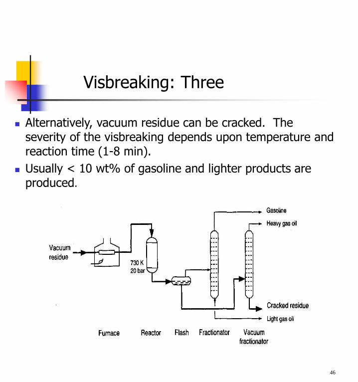
Alternatively, vacuum residue can be cracked. The severity of the visbreaking depends upon temperature and reaction time (1-8 min).
Usually < 10 wt% of gasoline and lighter products are produced.
46
Visbreaking: Three
Delayed Coking: One
Coking is a severe method of thermal cracking used to upgrade heavy residuals into lighter products or distillates.
Coking produces straight-run gasoline (Coker naphtha) and various middle-distillate fractions used as catalytic cracking feedstock.
The process completely reduces hydrogen so that the residue is a form of carbon called "coke."
Three typical types of coke are obtained (sponge coke, honeycomb coke, and needle coke) depending upon the reaction mechanism, time, temperature, and the crude feedstock.
In delayed coking the heated charge (typically residuum from atmospheric distillation towers) is transferred to large coke drums which provide the long residence time needed to allow the cracking reactions to proceed to completion.
47
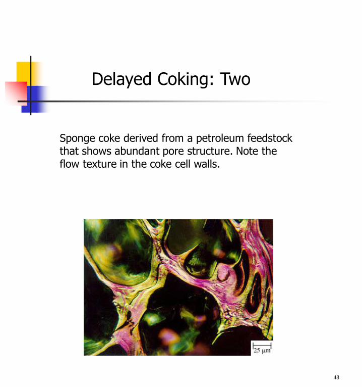
Sponge coke derived from a petroleum feedstock that shows abundant pore structure. Note the flow texture in the coke cell walls.
48
Delayed Coking: Two

Typical needle coke derived from a petroleum feedstock. The parallel layers and linear fractures are distinctive and provide slip planes to relieve stress in the coke .
49
Delayed Coking: Three
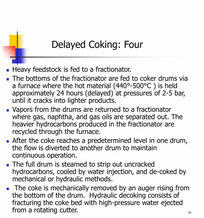
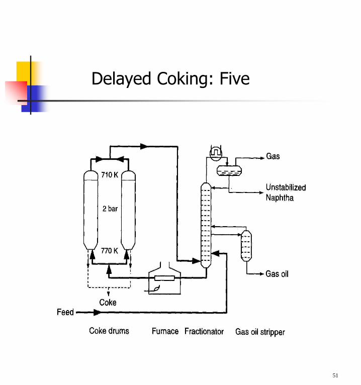
Heavy feedstock is fed to a fractionator.
The bottoms of the fractionator are fed to coker drums via a furnace where the hot material (440°-500°C ) is held approximately 24 hours (delayed) at pressures of 2-5 bar, until it cracks into lighter products.
Vapors from the drums are returned to a fractionator where gas, naphtha, and gas oils are separated out. The heavier hydrocarbons produced in the fractionator are recycled through the furnace.
After the coke reaches a predetermined level in one drum, the flow is diverted to another drum to maintain continuous operation.
The full drum is steamed to strip out uncrackedhydrocarbons, cooled by water injection, and de-coked by mechanical or hydraulic methods.
The coke is mechanically removed by an auger rising from the bottom of the drum. Hydraulic decoking consists of fracturing the coke bed with high-pressure water ejected from a rotating cutter. 50
Delayed Coking: Four
51
Delayed Coking: Five
Catalytic Processes: One
Fluid Catalytic Cracking (FCC)
Hydrotreating
Hydrocracking
Catalytic Reforming
Alkylation
52
53
Catalytic Processes: Two
54
Catalytic Processes: Three
Catalytic Cracking: One
Main incentive for catalytic cracking is the need to increase gasoline
production.
Feedstocks are typically vacuum gas oil.
Cracking is catalyzed by solid acids which promote the rupture of C-C bonds. The crucial intermediates are carbocations (+ve charged HC ions) formed by the action of the acid sites on the catalyst.
Besides C-C cleavage many other reactions occur:- isomerization- protonation and deprotonation- alkylation- polymerization- cyclization and condensation
55

Catalytic cracking comprises a complex network of reactions, both intra-molecular and inter-molecular.
The formation of coke is an essential feature of the cracking process and this coke deactivates the catalyst.
Catalytic cracking is one of the largest applications of catalysts: worldwide cracking capacity exceeds 500 million t/a.
Catalytic cracking was the first large-scale application of fluidized beds which explains the name fluid catalytic cracking (FCC).
Nowadays entrained-flow reactors are used instead of fluidized beds but the name FCC is still retained.
56
Catalytic Cracking: Two
Fluid Catalytic Cracking: One
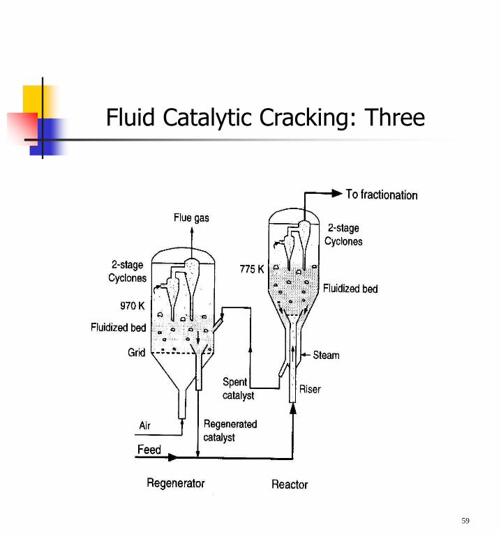
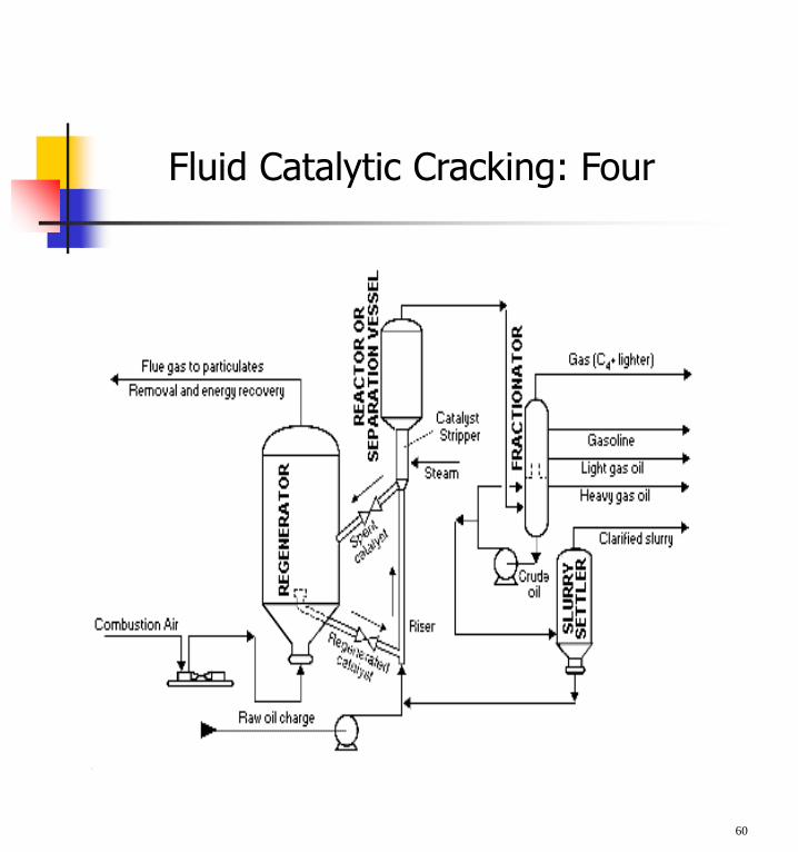
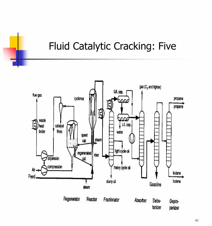
Oil is cracked in the presence of a finely divided catalyst, which is maintained in an aerated or fluidized state by the oil vapours.
The fluid cracker consists of a catalyst section and a fractionating section that operate together as an integrated processing unit.
The catalyst section contains the reactor and regenerator, which, with the standpipe and riser, form the catalyst circulation unit. The fluid catalyst is continuously circulated between the reactor and the regenerator using air, oil vapors, and steam as the conveying media.
Preheated feed is mixed with hot, regenerated catalyst in the riser and combined with a recycle stream, vapourized, and raised to reactor temperature (485-540°C) by the hot catalyst.
As the mixture travels up the riser, the charge is cracked at 0.7-2 bar.
In modern FCC units, all cracking takes place in the riser and the "reactor" merely serves as a holding vessel for the cyclones. Cracked product is then charged to a fractionating column where it is separated into fractions, and some of the heavy oil is recycled to the riser.
57
Spent catalyst is regenerated to get rid of coke that collects on the catalyst during the process.
Spent catalyst flows through the catalyst stripper to the regenerator, where most of the coke deposits burn off at the bottom where preheated air and spent catalyst are mixed.
Fresh catalyst is added and worn-out catalyst removed to optimize the cracking process.
58
Fluid Catalytic Cracking: Two
59
Fluid Catalytic Cracking: Three
60
Fluid Catalytic Cracking: Four
61
Fluid Catalytic Cracking: Five
Hydrotreating
Catalytic hydrotreating is a hydrogenation process used to remove about 90% of contaminants such as nitrogen, sulfur, oxygen, and metals from liquid petroleum fractions.
If these contaminants are not removed from the petroleum fractions they can have detrimental effects on equipment, catalysts, and the quality of the finished product.
Typically, hydrotreating is done prior to processes such as catalytic reforming so that the catalyst is not contaminated by untreated feedstock. Hydrotreating is also used prior to catalytic cracking to reduce sulfur and improve product yields, and to upgrade middle-distillate petroleum fractions into finished kerosene, diesel fuel, and heating fuel oils.
In addition, hydrotreating converts olefins and aromatics to saturated compounds.
62
Catalytic Hydrodesulfurization Process: One
Hydrotreating for sulfur removal is calledhydrodesulfurization.
In a typical catalytic hydrodesulfurization unit, thefeedstock is deaerated and mixed with hydrogen,preheated in a fired heater (315°-425° C) and thencharged under pressure (up to 70 bar) through a trickle-bed catalytic reactor.
In the reactor, the sulfur and nitrogen compounds in thefeedstock are converted into H2S and NH3.
The reaction products leave the reactor and after coolingto a low temperature enter a liquid/gas separator. Thehydrogen-rich gas from the high-pressure separation isrecycled to combine with the feedstock, and the low-pressure gas stream rich in H2S is sent to a gas treatingunit where H2S is removed.
63
The clean gas is then suitable as fuel for the refinery furnaces. The liquid stream is the product from hydrotreating and is normally sent to a stripping column for removal of H2S and other undesirable components.
In cases where steam is used for stripping, the product is sent to a vacuum drier for removal of water.
Hydrodesulfurized products are blended or used as catalytic reforming feedstock.
64
Catalytic Hydrodesulfurization Process: Two
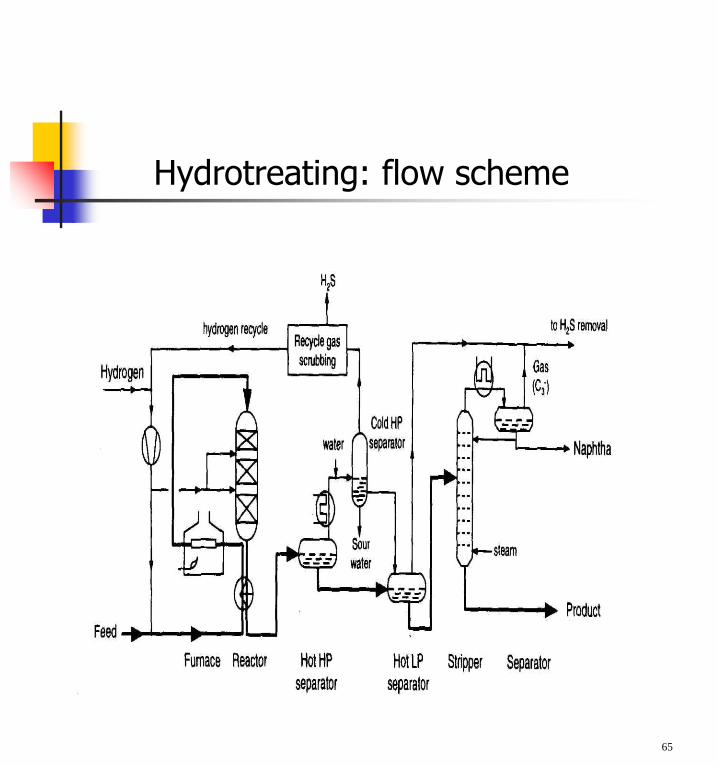
Hydrotreating: flow scheme
65
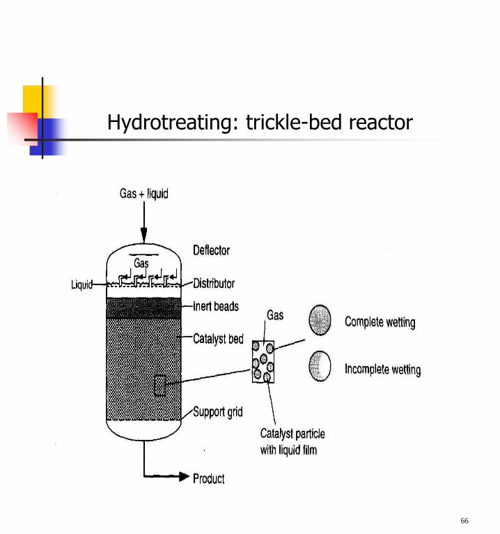
Hydrotreating: trickle-bed reactor
66
Hydrotreating Processes: One
Hydrotreating also can be used to improve the quality of pyrolysis gasoline (pygas), a by-product from the manufacture of ethylene.
Traditionally, the outlet for pygas has been motor gasoline blending, because of its high octane number. However, only small portions can be blended untreated owing to the unacceptable odor, color, and gum-forming tendencies of this material.
The quality of pygas, which is high in diolefincontent, can be satisfactorily improved by hydrotreating, whereby conversion of diolefins into mono-olefins provides an acceptable product for motor gas blending.
67
Hydrotreating processes differ depending upon thefeedstock available and catalysts used.
Hydrotreating can be used to improve the burningcharacteristics of distillates such as kerosene. byconverting aromatics into naphthenes, which are cleaner-burning compounds.
Lube-oil hydrotreating uses hydrogen to improve productquality. With mild lube hydrotreating saturation of olefinsand improvements in color, odor, and acid nature of the oilare achieved. Operating temperatures and pressures areusually below 315° C and 60 bar. Severe lubehydrotreating (T ~ 315 - 400°C and hydrogen pressuresup to 205 bar) is capable of saturating aromatic rings,along with sulfur and nitrogen removal, to impart specificproperties not achieved at mild conditions.
68
Hydrotreating Processes: Two
Hydrocracking: One
Hydrocracking is a two-stage process combining catalyticcracking and hydrogenation, wherein heavier feedstockis cracked in the presence of hydrogen to produce moredesirable products.
The process employs high pressure, high temperature, acatalyst, and hydrogen. Hydrocracking is used forfeedstock that are difficult to process by either catalyticcracking or reforming, since these feedstock arecharacterized usually by a high polycyclic aromaticcontent and/or high concentrations of the two principalcatalyst poisons, sulfur and nitrogen compounds.
The process largely depends on the nature of thefeedstock and the relative rates of the two competingreactions, hydrogenation and cracking. Heavy aromaticfeedstock is converted into lighter products under a widerange of very high pressures (70-140 bar) and fairly hightemperatures (400°-800°C), in the presence of hydrogenand special catalysts. 69
When the feedstock has a high paraffinic content, the primary function of hydrogen is to prevent the formation of polycyclic aromatic compounds.
Another important role of hydrogen in the hydrocracking process is to reduce tar formation and prevent buildup of coke on the catalyst.
Hydrogenation also serves to convert sulfur and nitrogen compounds present in the feedstock to hydrogen sulfide and ammonia.
Hydrocracking produces relatively large amounts of isobutane for alkylation feedstock and also performs isomerization for pour-point control and smoke-point control, both of which are important in high-quality jet fuel.
70
Hydrocracking: Two
Preheated feedstock is mixed with recycledhydrogen and sent to the first-stage reactor,where catalysts convert sulfur and nitrogencompounds to H2S and NH3. Limitedhydrocracking also occurs.
After the hydrocarbon leaves the first stage, it iscooled and liquefied and run through aseparator. The hydrogen is recycled to thefeedstock.
The liquid is charged to a fractionator.
The fractionator bottoms are again mixed with ahydrogen stream and charged to the secondstage. Since this material has already beensubjected to some hydrogenation, cracking, andreforming in the first stage, the operations ofthe second stage are more severe (highertemperatures and pressures). Again, the secondstage product is separated from the hydrogenand charged to the fractionator.
71
Hydrocracking: Three
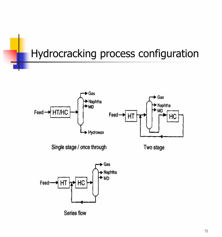
Hydrocracking process configuration
72
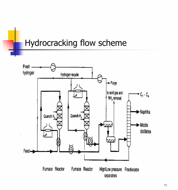
Hydrocracking flow scheme
73
Catalytic Reforming
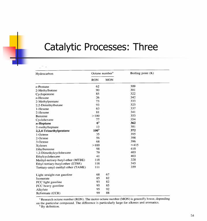
Catalytic reforming is an important process used to convert low-octane naphthas into high-octane gasoline blending components called reformates.
Reforming represents the total effect of numerous reactions such as cracking, polymerization, dehydrogenation, and isomerization taking place simultaneously.
Depending on the properties of the naphtha feedstock (as measured by the paraffin, olefin, naphthene, and aromatic content) and catalysts used, reformates can be produced with very high concentrations of benzene, toluene, xylene, (BTX) and other aromatics useful in gasoline blending and petrochemical processing.
Hydrogen, a significant by-product, is separated from the reformate for recycling and use in other processes.
74
75
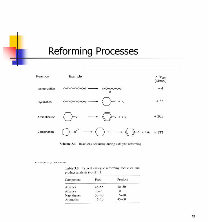
Reforming Processes
A catalytic reformer comprises a reactor and product-recovery section.
There is a feed preparation section comprising a combination of hydrotreatment and distillation.
Most processes use Pt as the active catalyst. Sometimes Pt is combined with a second catalyst (bimetallic catalyst) such as rhenium or another noble metal.
There are many different commercial processes including platforming, powerforming, ultraforming, and Thermofor catalytic reforming.
Some reformers operate at low pressure (3-13bar), others at high pressures (up to 70 bar).Some systems continuously regenerate the catalystin other systems. One reactor at a time is taken off-stream for catalyst regeneration, and some facilitiesregenerate all of the reactors during turnarounds.
76
Catalytic Reforming: One
In the platforming process, the first step is preparation of the naphtha feed to remove impurities from the naphtha and reduce catalyst degradation.
The naphtha feedstock is then mixed with hydrogen, vaporized, and passed through a series of alternating furnace and fixed-bed reactors containing a platinum catalyst.
The effluent from the last reactor is cooled and sent to a separator to permit removal of the hydrogen-rich gas stream from the top of the separator for recycling.
The liquid product from the bottom of the separator is sent to a fractionator called a stabilizer (butanizer). It makes a bottom product called reformate; butanes and lighter go overhead and are sent to the saturated gas plant.
77
Catalytic Reforming: Two
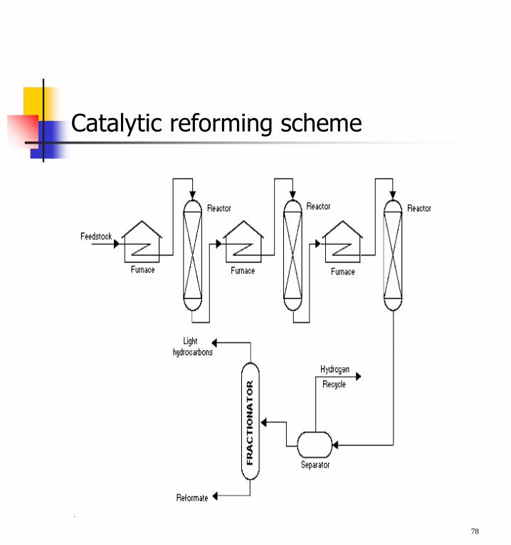
Catalytic reforming scheme
78

Regenerative catalytic reforming
79
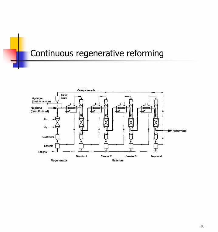
Continuous regenerative reforming
80
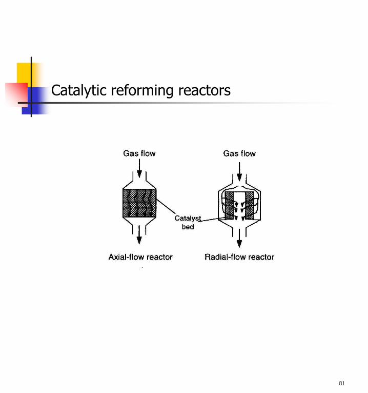
Catalytic reforming reactors
81
Alkylation
Alkylation combines low-molecular-weight olefins(primarily a mixture of propylene and butylene) withisobutene in the presence of a catalyst, eithersulfuric acid or hydrofluoric acid.
The product is called alkylate and is composed of amixture of high-octane, branched-chain paraffinichydrocarbons.
Alkylate is a premium blending stock because it hasexceptional antiknock properties and is clean burning.The octane number of the alkylate depends mainlyupon the kind of olefins used and upon operatingconditions.
82
Sulphuric acid alkylation process
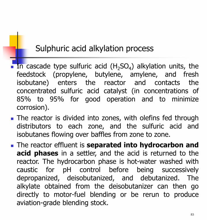
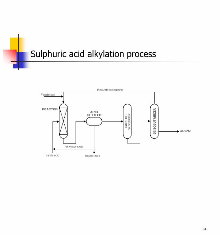
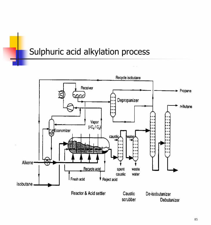
In cascade type sulfuric acid (H2SO4) alkylation units, thefeedstock (propylene, butylene, amylene, and freshisobutane) enters the reactor and contacts theconcentrated sulfuric acid catalyst (in concentrations of85% to 95% for good operation and to minimizecorrosion).
The reactor is divided into zones, with olefins fed throughdistributors to each zone, and the sulfuric acid andisobutanes flowing over baffles from zone to zone.
The reactor effluent is separated into hydrocarbon andacid phases in a settler, and the acid is returned to thereactor. The hydrocarbon phase is hot-water washed withcaustic for pH control before being successivelydepropanized, deisobutanized, and debutanized. Thealkylate obtained from the deisobutanizer can then godirectly to motor-fuel blending or be rerun to produceaviation-grade blending stock.
83
Sulphuric acid alkylation process
84
Sulphuric acid alkylation process
85
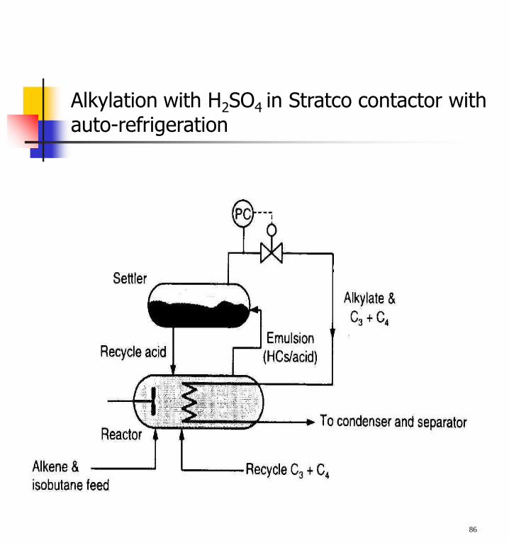
Alkylation with H2SO4 in Stratco contactor with auto-refrigeration
86
CONVERSION OF HEAVY RESIDUES
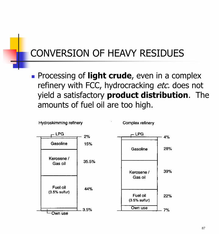
Processing of light crude, even in a complex refinery with FCC, hydrocracking etc. does not yield a satisfactory product distribution. The amounts of fuel oil are too high.
87
CONVERSION OF HEAVY RESIDUES
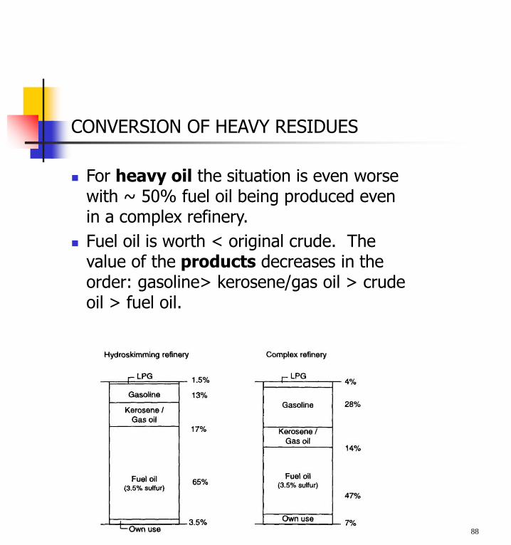
For heavy oil the situation is even worse with ~ 50% fuel oil being produced even in a complex refinery.
Fuel oil is worth < original crude. The value of the products decreases in the order: gasoline> kerosene/gas oil > crude oil > fuel oil.
88
CONVERSION OF HEAVY RESIDUES
There are several reasons for an increased incentive to convert fuel oil into lighter products:
1. The demand for light products such as gasoline and automotive diesel fuels continues to increase while market for heavy fuel oil is declining.
2. Environmental restrictions become more important. Fuel oil contains high amounts of S, N, and metals, so measures must be taken to lower emissions.
3. With the exception of Western Europe, the quality of crude oil shows a worsening trend. It becomes heavier with higher amounts of hetero-atoms, so more extensive processing is required to obtain the same amount and quality of products.
89
CONVERSION OF HEAVY RESIDUES
In principle there are two solutions for upgrading residual oils and for obtaining a better product distribution. These are carbon out and hydrogen in processes.
1. Examples of carbon rejection processes are the Flexicoking process (Exxon) and the FCC process discussed earlier.
2. Examples of hydrogen addition processes are the LC-fining process (Lummus) and the HYCON process (Shell).
90
Fluid Coking and Flexicoking
Both FLUID COKINGTM and FLEXICOKINGTM use fluid bed technology to thermally convert heavy oils such as vacuum residue, atmospheric residue, tar sands bitumen, heavy whole crudes, deasphalter bottoms or cat plant bottoms.
FLEXICOKING goes one step further than FLUID COKING: in addition to generating clean liquids, FLEXICOKING also produces a low-BTU gas in one integrated processing step that can virtually eliminate petroleum coke production.
The advantages are: flexibility to handle a variety of feed types; high reliability with the average service factor between 90 -95%; large single train capacity provides an economy of scale that lowers investment cost; able to process 65 kB/SD of 20 wt% Conradson Carbon resid in a single reactor; time between turnarounds routinely approaches two years; able to process very heavy feed stocks such as deasphalter bottoms at high feed rates.
Additional FLEXICOKING benefit: Integrated gasification of up to 97% of gross coke production
91

The Fluid Coking Process
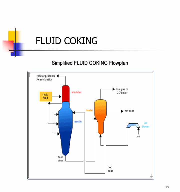
The fluid coking residuum conversion process uses non-catalytic, thermal chemistry to achieve high conversion levels with even the heaviest refinery feedstocks.
Since most of the sulfur, nitrogen, metals, and Conradson Carbon Residue feed contaminants are rejected with the coke, the full-range of lighter products can be feed for an FCC unit.
Use as a single train reduces manpower requirements and avoids process load swings and frequent thermal cycles that are typical of batch processes such as delayed coking.
The configurations available with fluid coking are: extinction recycle, once-through, and once-through with hydroclones.
92
93
FLUID COKING
The Flexicoking Process
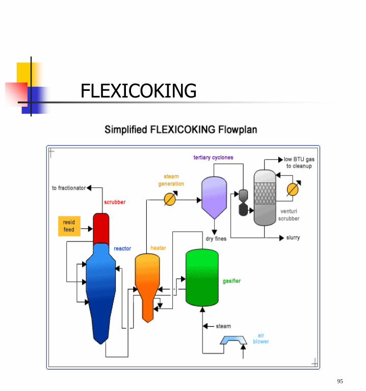
Flexicoking is a thermal technology for converting heavy feedstocks to higher margin liquids and producing, a low BTU gas, instead of coke.
The conversion of coke to clean fuel gas maximizes refinery yield of hydrocarbons.
The carbon rejection process results in lower hydrogen consumption than alternative hydrogen-addition systems.
The low BTU gas is typically fed to a CO boiler for heat recovery but can also be used in modified furnaces/boilers; atmospheric or vacuum pipestill furnaces; reboilers; waste heat boilers; power plants and steel mills; or as hydrogen plant fuel, which can significantly reduce or eliminate purchases of expensive natural gas.
The small residual coke produced can be sold as boiler fuel for generating electricity and steam or as burner fuel for cement plants.
94
95
FLEXICOKING
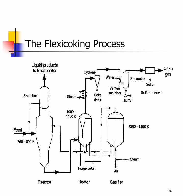
The Flexicoking Process
96
Catalytic hydrogenation of residues
This is a “hydrogen-in” route.
It serves two purposes: removal of Sulphur, Nitrogen and metal compounds, and the production of light products.
Reactions are similar to those occurring in hydrotreating and hydrocracking of gas oils, but there are two important differences.
(1) Residues contain much higher amounts of sulphur, nitrogen and polycyclic aromatic compounds; and
(2) removal of metals, which are concentrated in the residual fraction of the crude, means that operating conditions are more severe and hydrogen consumption greater than for hydroprocessing of gas oils.
97
Catalyst deactivation
Deposition of metals causes catalyst deactivation.
Basically all metals in the periodic table are present in crude oil with the major ones being Ni and V.
At the reaction conditions H2S is present, hence metal sulphides are formed.
The reaction scheme is complex but may be represented simply as:
Ni-porphyrin + H2 NiS + hydrocarbons and
V-porphyrin + H2 V2S3 + hydrocarbons
The catalyst is poisoned by this process because most of the deposition occurs on the outer shell of the catalyst particles, initially poisoning the active sites then causing pore plugging.
98
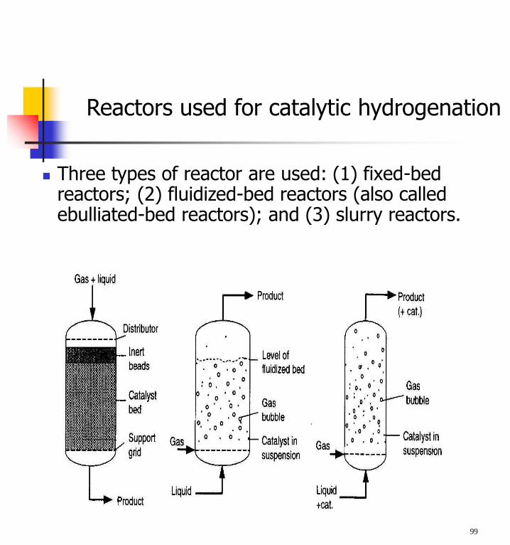
Reactors used for catalytic hydrogenation
Three types of reactor are used: (1) fixed-bed reactors; (2) fluidized-bed reactors (also called ebulliated-bed reactors); and (3) slurry reactors.
99
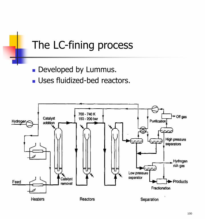
The LC-fining process
Developed by Lummus.
Uses fluidized-bed reactors.
100
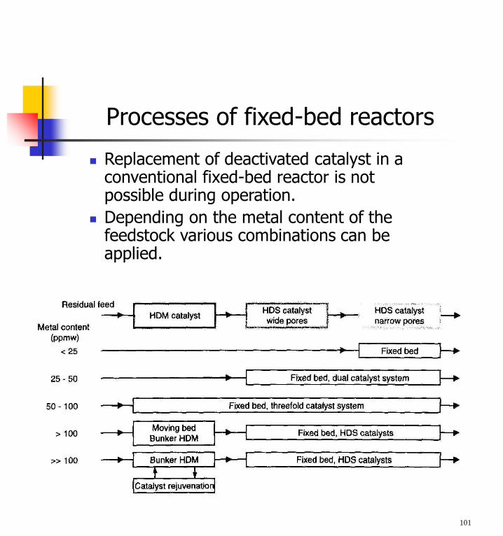
Processes of fixed-bed reactors
Replacement of deactivated catalyst in a conventional fixed-bed reactor is not possible during operation.
Depending on the metal content of the feedstock various combinations can be applied.
101
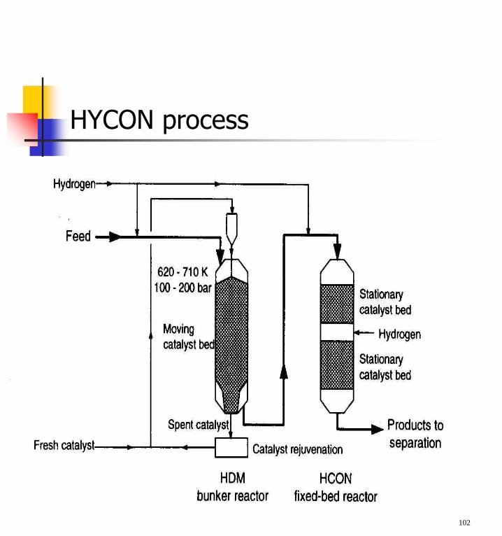
HYCON process
102
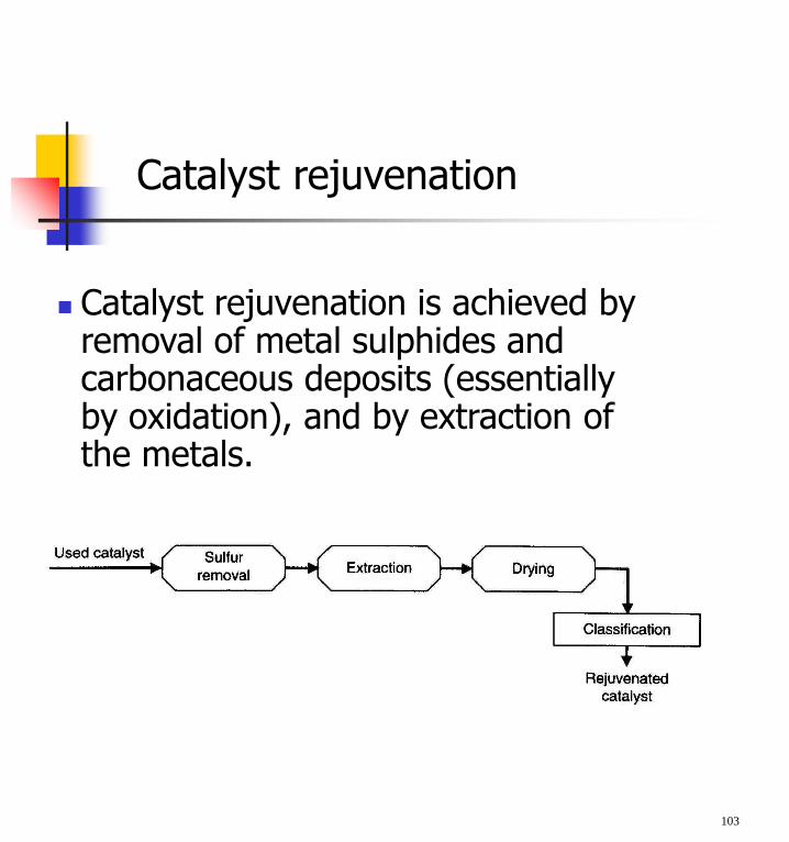
Catalyst rejuvenation
Catalyst rejuvenation is achieved by removal of metal sulphides and carbonaceous deposits (essentially by oxidation), and by extraction of the metals.
103
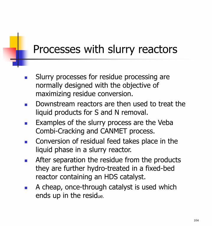
Processes with slurry reactors
Slurry processes for residue processing are normally designed with the objective of maximizing residue conversion.
Downstream reactors are then used to treat the liquid products for S and N removal.
Examples of the slurry process are the Veba Combi-Cracking and CANMET process.
Conversion of residual feed takes place in the liquid phase in a slurry reactor.
After separation the residue from the products they are further hydro-treated in a fixed-bed reactor containing an HDS catalyst.
A cheap, once-through catalyst is used which ends up in the residue.
104
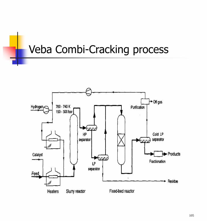
Veba Combi-Cracking process
105
TREATMENT OF REFINERY GASES
Removal of H2S from gases is usually performed by absorption in the liquid phase.
The concentrated H2S is frequently converted to elemental sulphur by the “Claus” process (partial oxidation of H2S)
In the Claus process 95-97% of the H2S is converted.
H2S is often removed with solvents that can be regenerated, usually alkanolamines: e.g. CH2(OH)CH2NH2 MEA (mono-ethanolamine).
These amines are highly water soluble with low volatility and their interaction with H2S is much faster than with CO2 so that the amount of absorbed CO2
can be limited by selecting appropriate conditions.
106
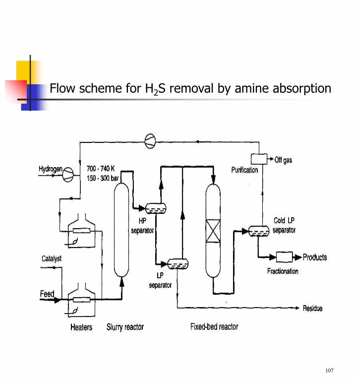
Flow scheme for H2S removal by amine absorption
107
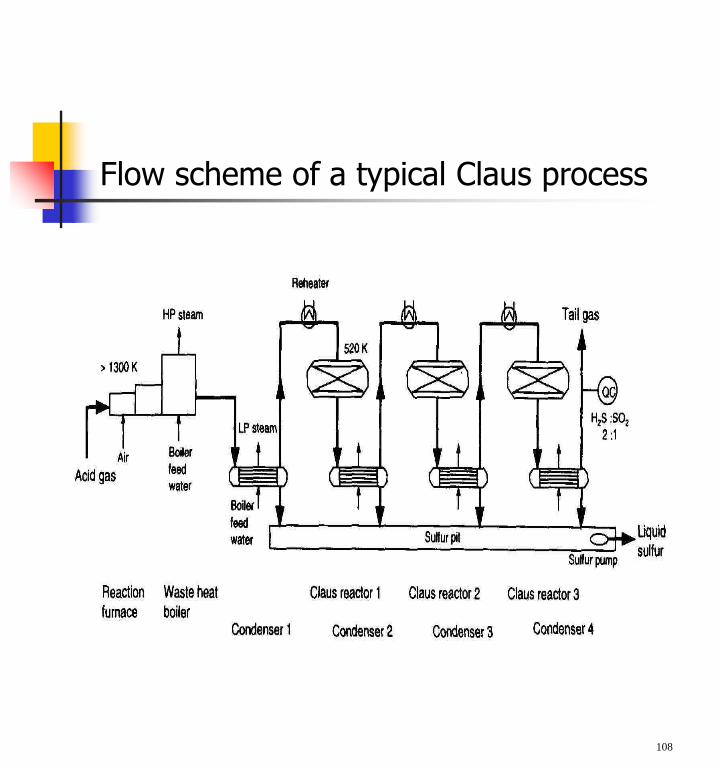
Flow scheme of a typical Claus process
108