Embed Size (px)
Citation preview
1
Oil & Natural Gas Technology
DOE Award No.: DE-FE0009897
Quarterly Research Performance Progress Report (Period ending 6/30/2015)
Hydrate-Bearing Clayey Sediments: Morphology, Physical Properties, Production
and Engineering/Geological Implications
Project Period (10/1/2012 to 9/30/2016)
Submitted by: J. Carlos Santamarina
Georgia Institute of Technology
DUNS #: 097394084 505 10th street
Atlanta , GA 30332 e-mail: [email protected]
Phone number: (404) 894-7605
Prepared for: United States Department of Energy
National Energy Technology Laboratory
Submission date: 8/12/2015
Office of Fossil Energy
2
DISCLAIMER: This report was prepared as an account of work sponsored by an agency of the United States Government. Neither the United States Government nor any agency thereof, nor any of their employees, makes any warranty, express or implied, or assumes any legal liability or responsibility for the accuracy, completeness, or usefulness of any information, apparatus, product, or process disclosed, or represents that its use would not infringe privately owned rights. Reference herein to any specific commercial product, process, or service by trade name, trademark, manufacturer, or otherwise does not necessarily constitute or imply its endorsement, rec-ommendation, or favoring by the United States Government or any agency thereof. The views and opinions of authors expressed herein do not nec-essarily state or reflect those of the United States Government or any agency thereof.
3
ACCOMPLISHMENTS
Context – Goals. Fine grained sediments host more than 90% of the global gas hydrate
accumulations. Yet, hydrate formation in clayey sediments is least understood and characterized.
This research focuses on hydrate bearing clayey sediments. The goals of this research are (1) to
gain a fundamental understanding of hydrate formation and ensuing morphology, (2) to develop
laboratory techniques to emulate “natural” formations, (3) to assess and develop analytical
tools to predict physical properties, (4) to evaluate engineering and geological implications, and
(5) to advance gas production alternatives to recover methane from these sediments.
Accomplished
The main accomplishments for this period include:
Formation of CO2 hydrate in fine-grained sediment
o Transformation from ice/water to hydrate in hydrophobic silica
Quantified mass, and advanced thermal analysis of hydrate formation in fine-grained
sediment
Crystal formation experiments in porous media
Plan - Next reporting period
Physical understanding of hydrate formation in fine grained sediments and small pores. Evaluate
the difference between gas pressure, liquid pressure and crystal pressure, and the relevance to
hydrate stability. Advance Numerical model studies of physical properties of hydrate bearing
sediments. Well production simulation with numerical methods.
Research in Progress
The following pages capture the slides presented at the meeting for the end of year 3, which
include specific information about this quarter.
8/14/2015
1
DOE - National Energy Technology Laboratory Agreement: DE-FE0009897
Hydrate-Bearing Clayey Sediments Morphology, Physical Properties, Production
and Engineering/Geological Implications
Transition to Phase 4 / Budget Period 4
J. Carlos Santamarina
Georgia Institute of Technology(on leave at KAUST)
L Goals – Objectives - Background
Natural HBF – Fine Grained (Analogues)
Underlying Physics
Devices
Hydrate Formation in the Lab
“Reservoir” Simulation
Physical Properties
Gas Production
Next – Team – Schedule
8/14/2015
2
Goals and Objectives
Background
(additional examples: see 2014 End of Year Report)
Goals and Objectives
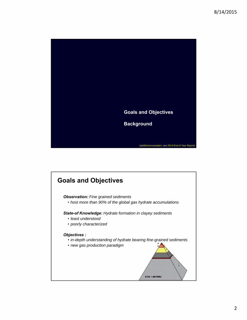
Observation: Fine grained sediments • host more than 90% of the global gas hydrate accumulations
State-of Knowledge: Hydrate formation in clayey sediments • least understood • poorly characterized
Objectives :• in-depth understanding of hydrate bearing fine-grained sediments• new gas production paradigm
8/14/2015
3
Goals and Objectives
The proposed research
• focus: hydrate bearing clayey sediments
• fundamental understanding of hydrate formation
• hydrate lens topology
• laboratory techniques to emulate “natural” formations
• analytical tools to predict physical properties
• engineering and geological implications
• gas production alternatives
Project Tasks
Focus: hydrate bearing clayey sediments
Tasks:
• fundamental understanding of hydrate formation in fine-grained sed.
• laboratory emulation with real methane hydrate
• assessment and prediction of physical properties
• evaluation of engineering and geological implications
• possible paradigm shift in gas production from fine-grained sed.
8/14/2015
4
Task 2 - Formation, distribution, topology
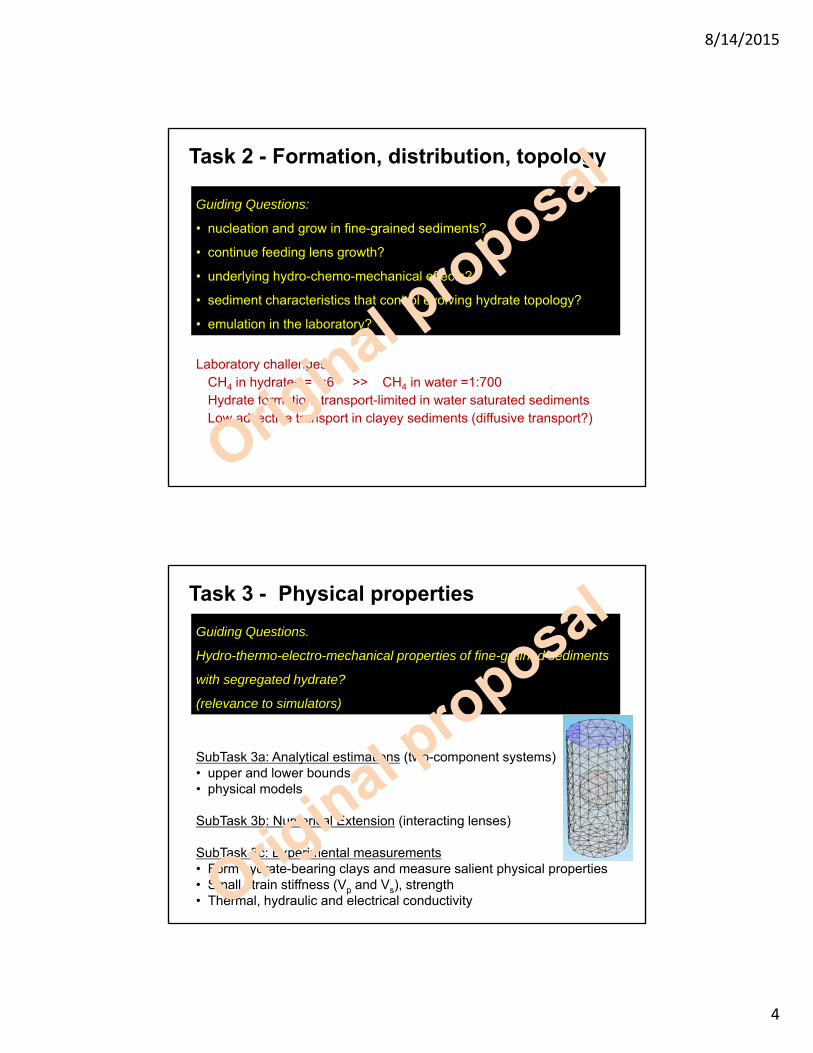
Guiding Questions:
• nucleation and grow in fine-grained sediments?
• continue feeding lens growth?
• underlying hydro-chemo-mechanical effects?
• sediment characteristics that control evolving hydrate topology?
• emulation in the laboratory?
Laboratory challengesCH4 in hydrates = 1:6 >> CH4 in water =1:700Hydrate formation: transport-limited in water saturated sedimentsLow advective transport in clayey sediments (diffusive transport?)
Task 3 - Physical properties
SubTask 3a: Analytical estimations (two-component systems)• upper and lower bounds • physical models
SubTask 3b: Numerical Extension (interacting lenses)
SubTask 3c: Experimental measurements• Form hydrate-bearing clays and measure salient physical properties• Small strain stiffness (Vp and Vs), strength• Thermal, hydraulic and electrical conductivity
Guiding Questions.
Hydro-thermo-electro-mechanical properties of fine-grained sediments
with segregated hydrate?
(relevance to simulators)
8/14/2015
5
Task 4 - Gas Production
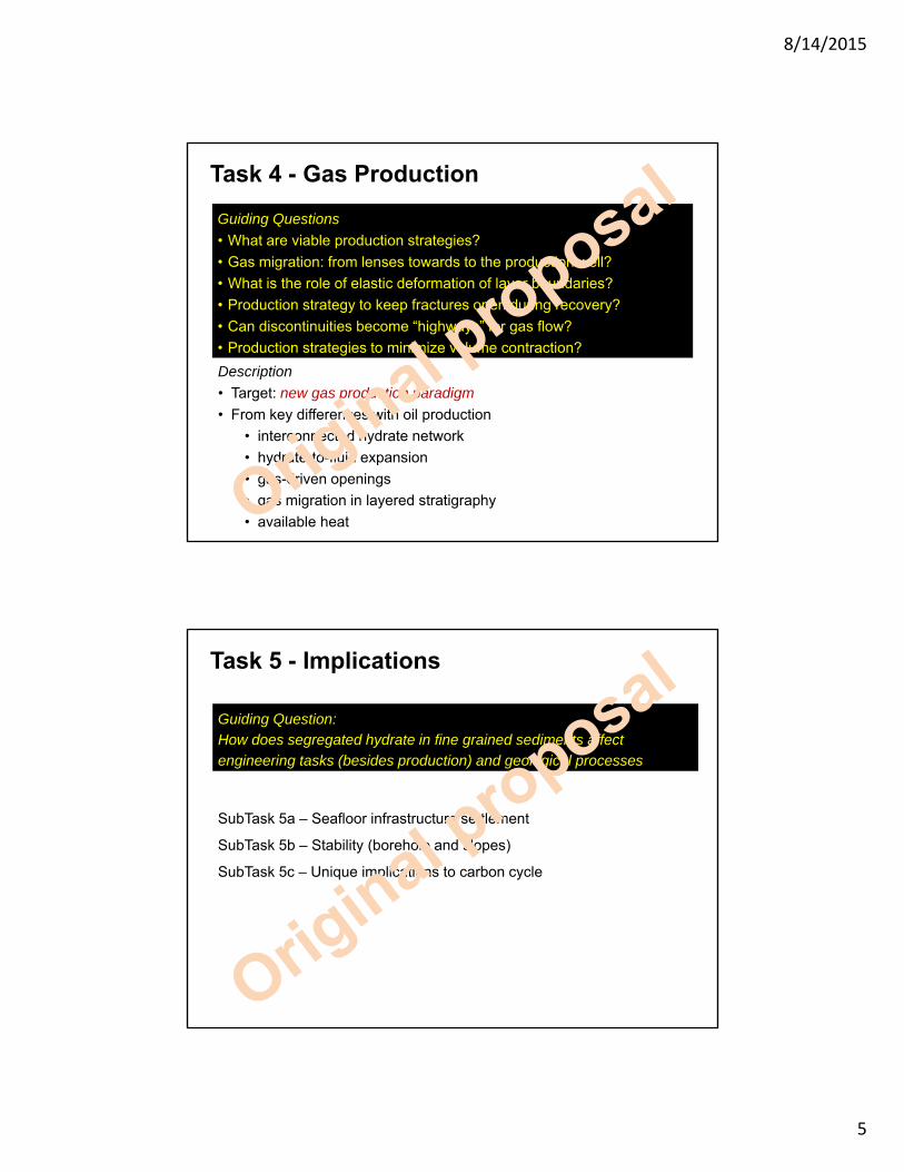
Description
• Target: new gas production paradigm
• From key differences with oil production
• interconnected hydrate network
• hydrate-to-fluid expansion
• gas-driven openings
• gas migration in layered stratigraphy
• available heat
Guiding Questions
• What are viable production strategies?
• Gas migration: from lenses towards to the production well?
• What is the role of elastic deformation of layer boundaries?
• Production strategy to keep fractures open during recovery?
• Can discontinuities become “highways” for gas flow?
• Production strategies to minimize volume contraction?
Task 5 - Implications
SubTask 5a – Seafloor infrastructure settlement
SubTask 5b – Stability (borehole and slopes)
SubTask 5c – Unique implications to carbon cycle
Guiding Question:
How does segregated hydrate in fine grained sediments affect
engineering tasks (besides production) and geological processes
8/14/2015
6
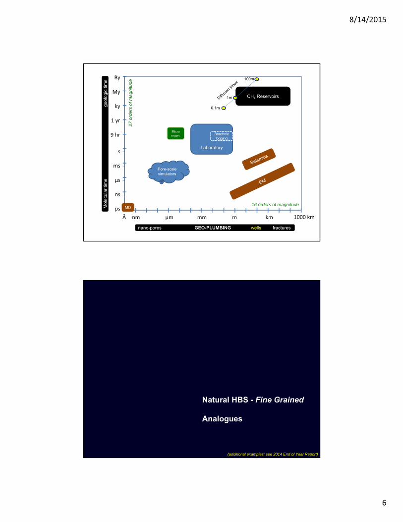
nm µm mm m km
ky
By
My
1 yr
9 hr
s
ms
µs
ns
27 o
rder
s of
mag
nitu
de
16 orders of magnitude
1000 km
CH4 Reservoirs
ps
Å
MD
nano-pores GEO-PLUMBING wells fractures
Laboratory
Borehole logging
Micro organ.
Pore-scale simulators
Mol
ecul
ar ti
me
geol
ogic
tim
e 100m
1m
0.1m
Natural HBS - Fine Grained
Analogues
(additional examples: see 2014 End of Year Report)
8/14/2015
7
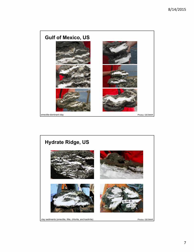
Gulf of Mexico, US
Photos: GEOMARsmectite-dominant clay
Hydrate Ridge, US
Photos: GEOMARclay sediments (smectite, illite, chlorite, and kaolinite)
8/14/2015
8
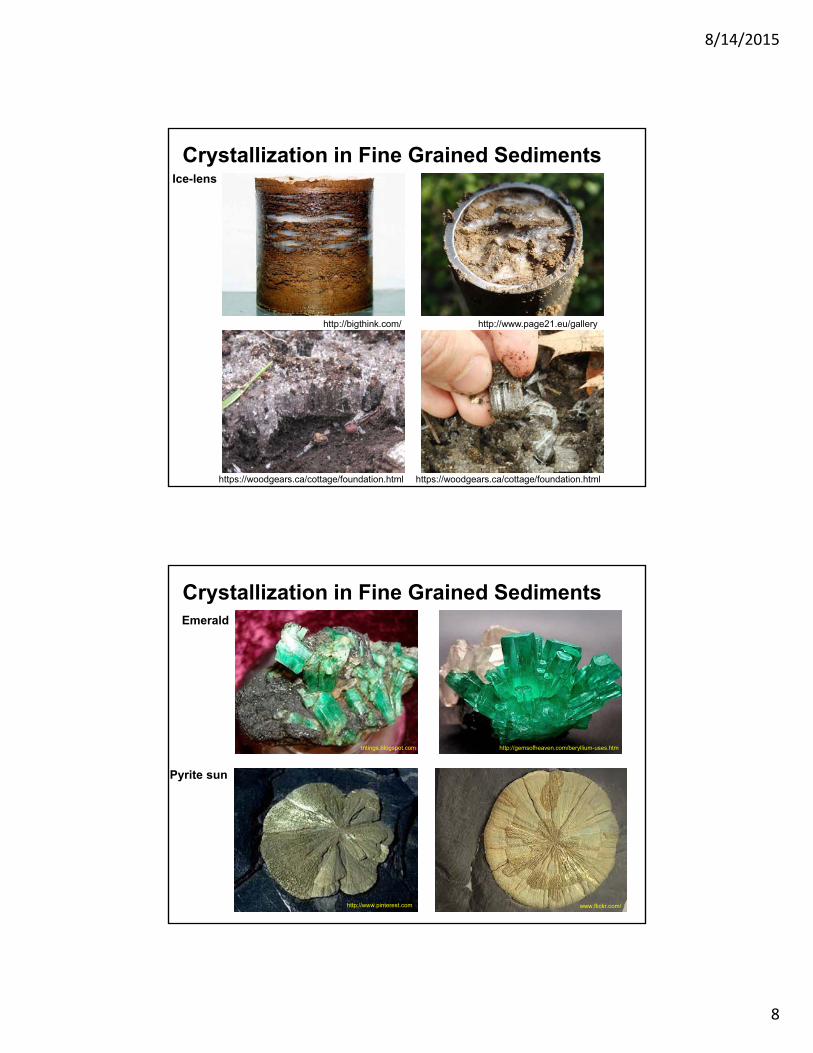
Crystallization in Fine Grained SedimentsIce-lens
http://bigthink.com/ http://www.page21.eu/gallery
https://woodgears.ca/cottage/foundation.html https://woodgears.ca/cottage/foundation.html
Crystallization in Fine Grained SedimentsEmerald
Pyrite sun
tntings.blogspot.com http://gemsofheaven.com/beryllium-uses.htm
www.flickr.com/http://www.pinterest.com
8/14/2015
9
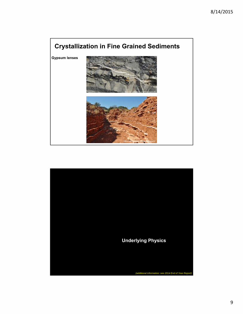
Crystallization in Fine Grained Sediments
Gypsum lenses
https://en.wikipedia.org/wiki/Gypsum
https://en.wikipedia.org/wiki/Gypsum
Underlying Physics
(additional information: see 2014 End of Year Report)
8/14/2015
10
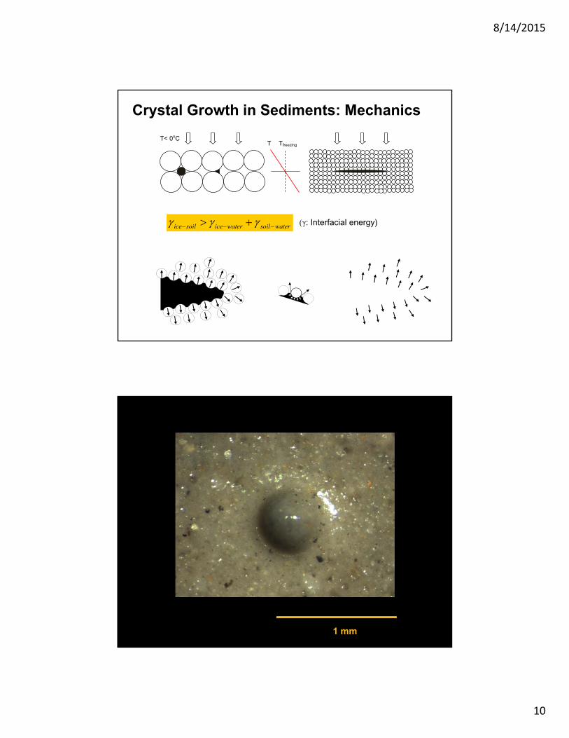
Tfreezing T
T< 0oC
watersoilwatericesoilice (γ: Interfacial energy)
Crystal Growth in Sediments: Mechanics
1 mm
8/14/2015
11
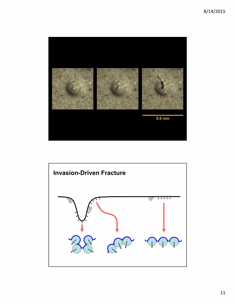
0.8 mm
Invasion-Driven Fracture
8/14/2015
12
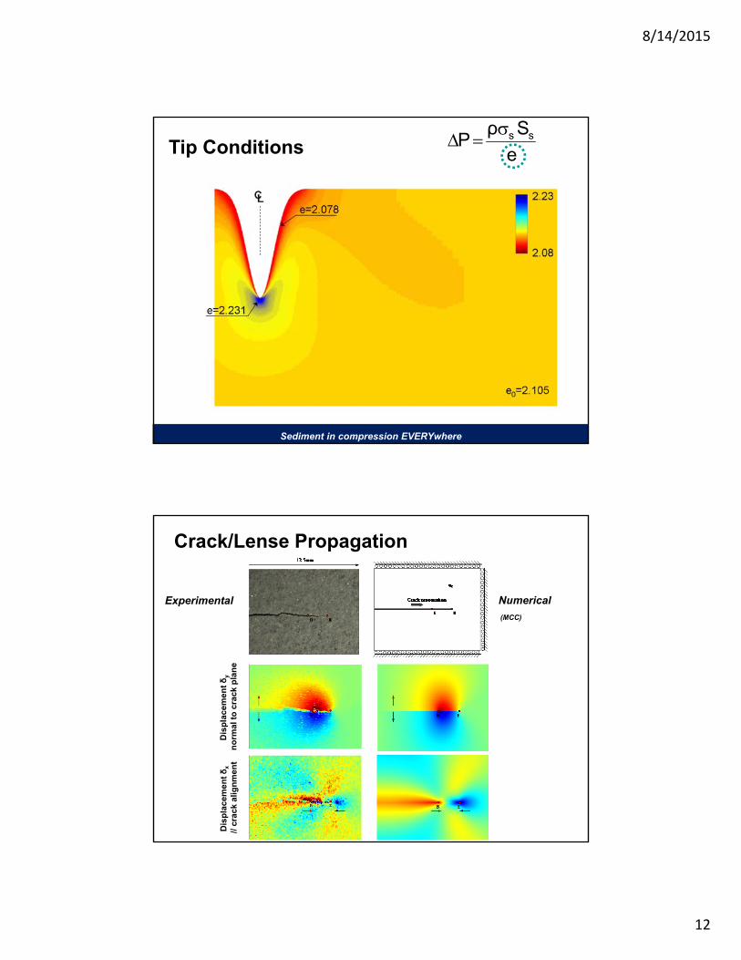
Tip Conditions e
SρP ss
Sediment in compression EVERYwhere
Experimental Numerical
Dis
pla
cem
ent δ
x
// cr
ack
alig
nm
ent
Dis
pla
cem
ent δ
y
no
rmal
to
cra
ck p
lan
e
Crack/Lense Propagation
(MCC)
8/14/2015
13
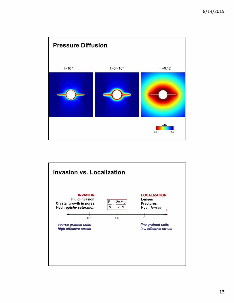
u/u0
1.00.0
T=10-4 T=5×10⁻⁴ T=0.12
Pressure Diffusion
1.0 100.1
LOCALIZATIONLensesFracturesHyd.: lenses
INVASIONFluid invasion
Crystal growth in poresHyd.: patchy saturation d'
2
N
F LVc
fine grained soilslow effective stress
coarse grained soilshigh effective stress
Invasion vs. Localization
8/14/2015
14
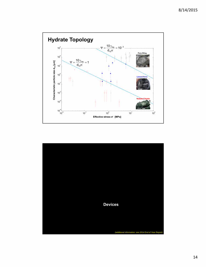
Hydrate Topology
10-2
10-1
100
101
102
10-4
10-3
10-2
10-1
100
101
102
103
Pore-filling
Lenses/Veins
Mt. Elbert
NGHP
Blake Ridge
Effective stress σ [MPa]
Ch
arac
teri
stic
par
ticl
e si
ze d
10[
m]
1d
10'
10
hw
Nodules/Chunks
3'
10
hw 10d
10
Devices
(additional information: see 2014 End of Year Report)
8/14/2015
15
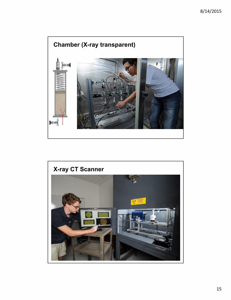
Chamber (X-ray transparent)
X-ray CT Scanner
8/14/2015
16
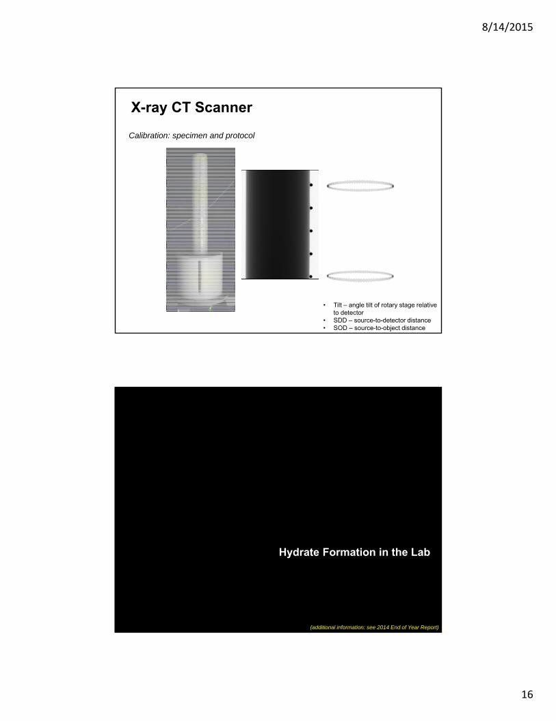
Calibration: specimen and protocol
X-ray CT Scanner
• Tilt – angle tilt of rotary stage relative to detector
• SDD – source-to-detector distance• SOD – source-to-object distance
Hydrate Formation in the Lab
(additional information: see 2014 End of Year Report)
8/14/2015
17
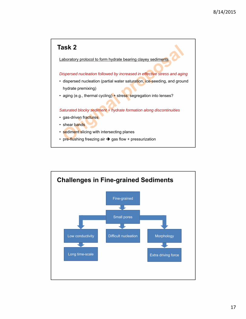
Laboratory protocol to form hydrate bearing clayey sediments
Dispersed nucleation followed by increased in effective stress and aging
• dispersed nucleation (partial water saturation, ice-seeding, and ground
hydrate premixing)
• aging (e.g., thermal cycling) + stress: segregation into lenses?
Saturated blocky sediment + hydrate formation along discontinuities
• gas-driven fractures
• shear bands
• sediment slicing with intersecting planes
• pre-flushing freezing air gas flow + pressurization
Task 2
Challenges in Fine-grained Sediments
Fine-grained
Small pores
Difficult nucleation Morphology
Extra driving force
Low conductivity
Long time-scale
8/14/2015
18
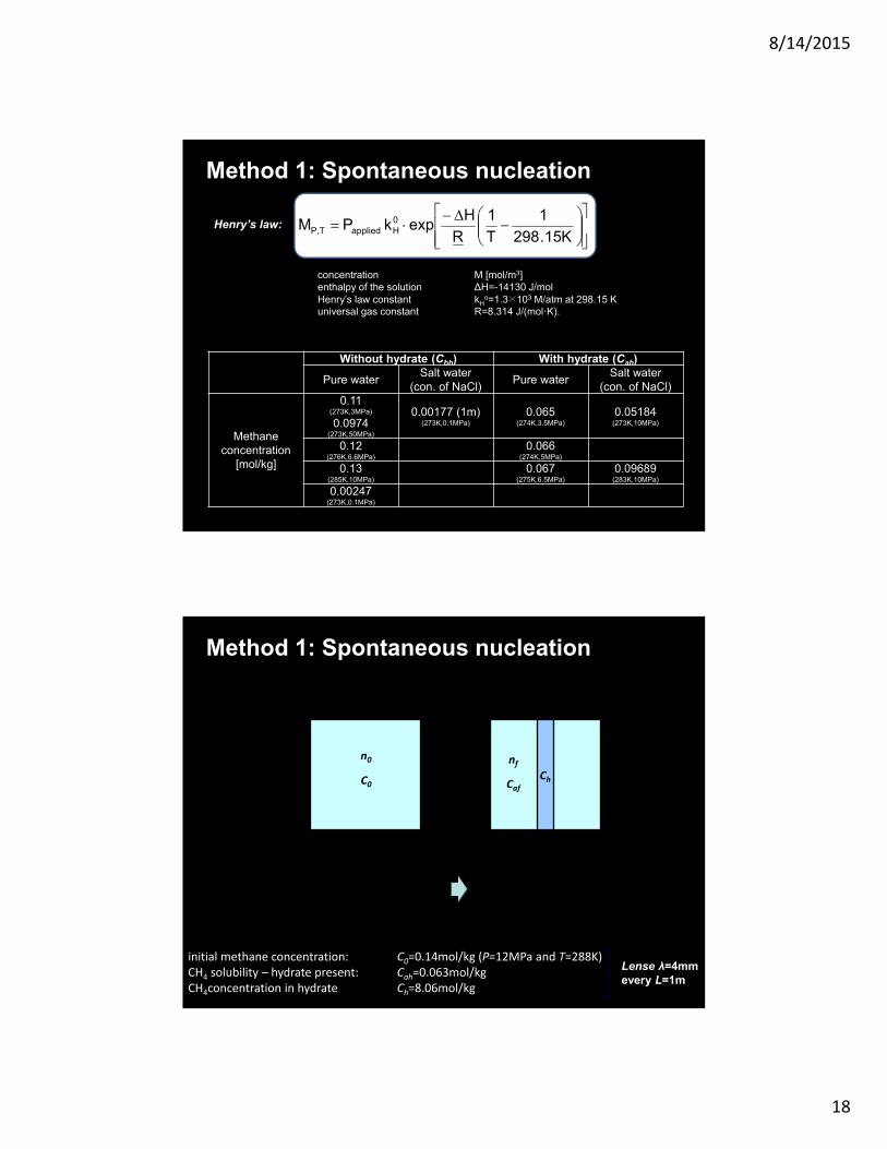
Henry’s law:
K15.298
1
T
1
R
HexpkPM 0
HappliedT,P
concentration M [mol/m3] enthalpy of the solution ∆H=-14130 J/molHenry’s law constant kH
o=1.3×10³ M/atm at 298.15 Kuniversal gas constant R=8.314 J/(mol·K).
Without hydrate (Cbh) With hydrate (Cah)
Pure waterSalt water
(con. of NaCl)Pure water
Salt water(con. of NaCl)
Methaneconcentration
[mol/kg]
0.11(273K,3MPa)
0.0974(273K,50MPa)
0.00177 (1m)(273K,0.1MPa)
0.065(274K,3.5MPa)
0.05184(273K,10MPa)
0.12(276K,6.6MPa)
0.066(274K,5MPa)
0.13(285K,10MPa)
0.067(275K,6.5MPa)
0.09689(283K,10MPa)
0.00247(273K,0.1MPa)
Method 1: Spontaneous nucleation
Method 1: Spontaneous nucleation
n0
C0Ch
nf
Caf
L L
Hydrate lens formationWater saturated sediment
00 n
CC
CC
L
λ
ahh
ah
λcλLCnLCn hahf 00
λL
λLnn f
0
λ
initial methane concentration: C0=0.14mol/kg (P=12MPa and T=288K)CH4 solubility – hydrate present: Cah=0.063mol/kgCH4concentration in hydrate Ch=8.06mol/kg
Lense λ=4mmevery L=1m
8/14/2015
19
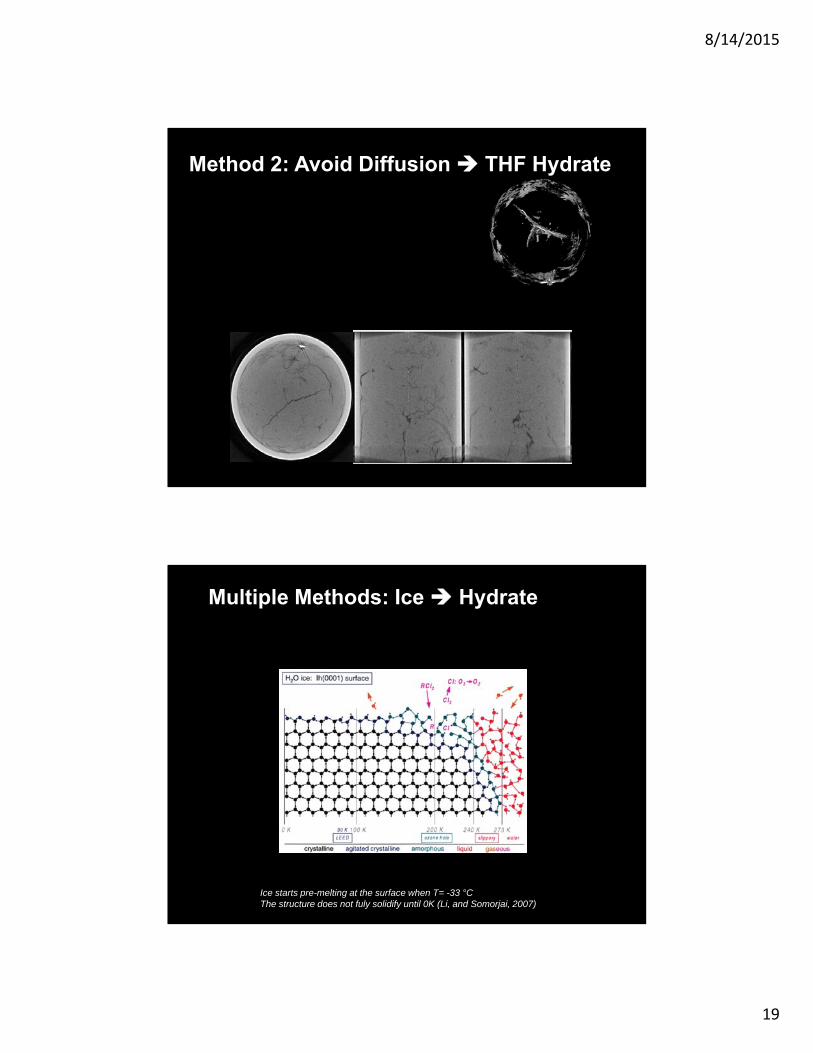
Method 2: Avoid Diffusion THF Hydrate
Ice starts pre-melting at the surface when T= -33 °CThe structure does not fuly solidify until 0K (Li, and Somorjai, 2007)
Multiple Methods: Ice Hydrate
8/14/2015
20
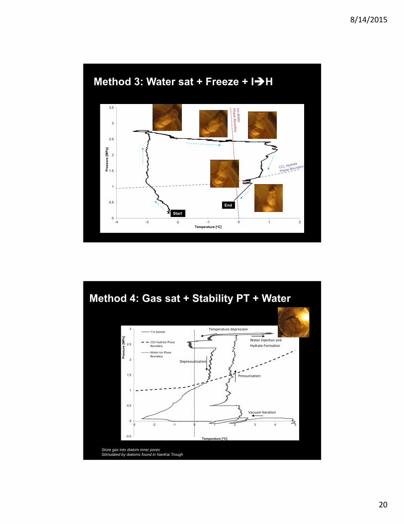
Method 3: Water sat + Freeze + IH
0
0.5
1
1.5
2
2.5
3
3.5
-4 -3 -2 -1 0 1 2
Pre
ssu
re [
MP
a]
Temperature [oC]
Start
End
-0.5
0
0.5
1
1.5
2
2.5
3
-3 -2 -1 0 1 2 3 4 5
Pre
ssu
re [
MP
a]
Temperature [°C]
T In Sample
CO2 Hydrate PhaseBoundary
Water‐Ice PhaseBoundary
Vacuum Iteration
Pressurization
Water Injection and
Hydrate Formation
Temperature depression
Depressurization
Method 4: Gas sat + Stability PT + Water
Store gas into diatom inner poresStimulated by diatoms found in NanKai Trough
8/14/2015
21
-0.5
0
0.5
1
1.5
2
2.5
3
3.5
-3 0 3 6 9 12
Pre
ssu
re [
MP
a]
Temperature [°C]
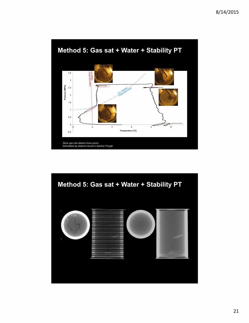
Store gas into diatom inner poresStimulated by diatoms found in NanKai Trough
StartEnd
Method 5: Gas sat + Water + Stability PT
Slide 42
Method 5: Gas sat + Water + Stability PT
8/14/2015
22
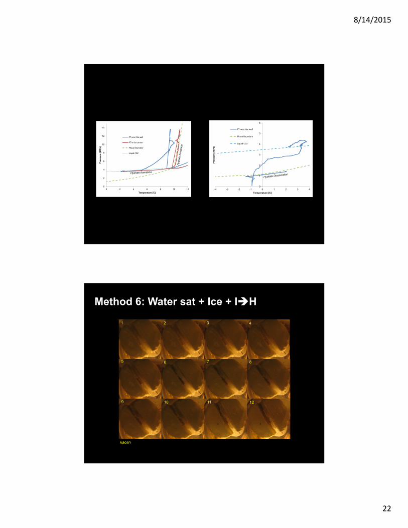
Slide 43
0
1
2
3
4
5
6
-4 -3 -2 -1 0 1 2 3 4
Pre
ssu
re [
MP
a]
Temperature [C]
PT near the wall
Phase Boundary
Liquid CO2
0
2
4
6
8
10
12
14
0 2 4 6 8 10 12
Pre
ssu
re [
MP
a]
Temperature [C]
PT near the wall
PT in the center
Phase Boundary
Liquid CO2
1 2 3 4
5 76 8
9 10 11 12
Method 6: Water sat + Ice + IH
kaolin
8/14/2015
23
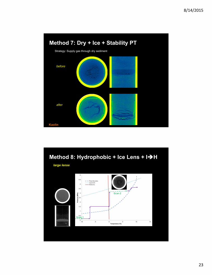
Slide 45
Method 7: Dry + Ice + Stability PTStrategy: Supply gas through dry sediment
before
after
Kaolin
Slide 46
0
0.5
1
1.5
2
2.5
3
3.5
4
4.5
5
-10 -5 0 5 10 15
Pre
ssu
re [
MP
a]
Temperature [°C]
Phase Boundary
Liquid CO2
Water/Ice
Scan 1
Scan 2
Method 8: Hydrophobic + Ice Lens + IHlarge lense
8/14/2015
24
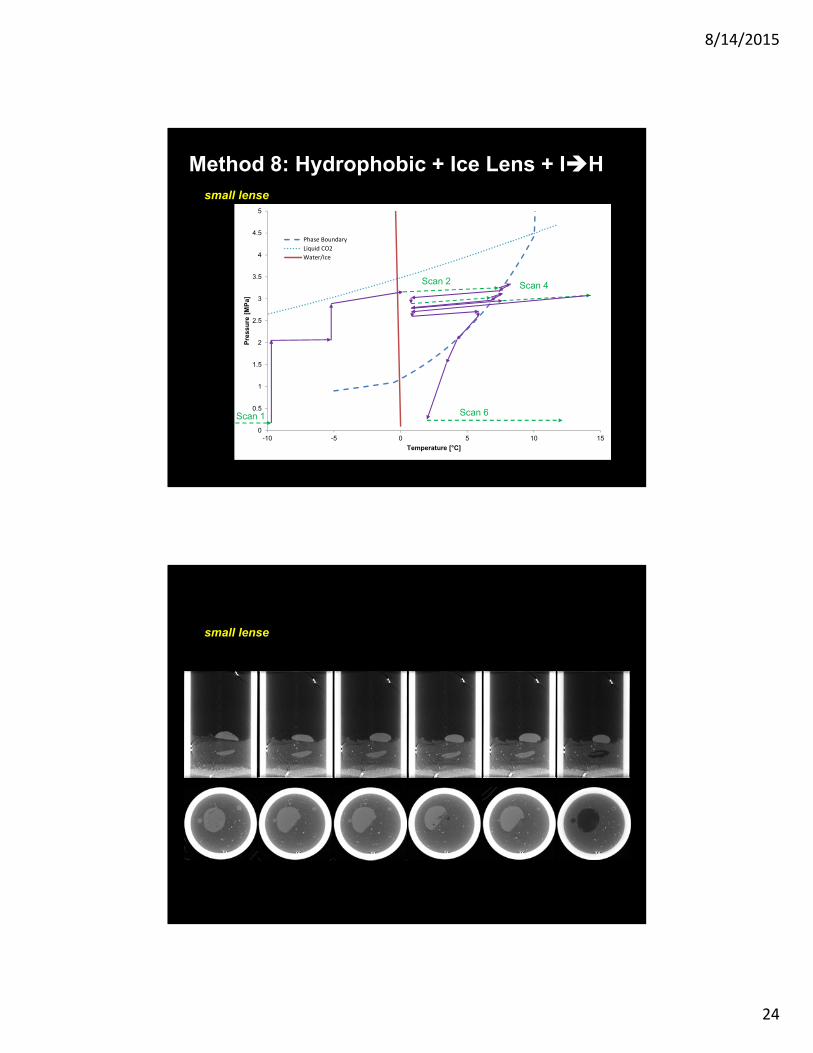
Slide 47
0
0.5
1
1.5
2
2.5
3
3.5
4
4.5
5
-10 -5 0 5 10 15
Pre
ssu
re [
MP
a]
Temperature [°C]
Phase Boundary
Liquid CO2
Water/Ice
Scan 1
Scan 2 Scan 4
Scan 6
Method 8: Hydrophobic + Ice Lens + IHsmall lense
Slide 48
small lense
8/14/2015
25
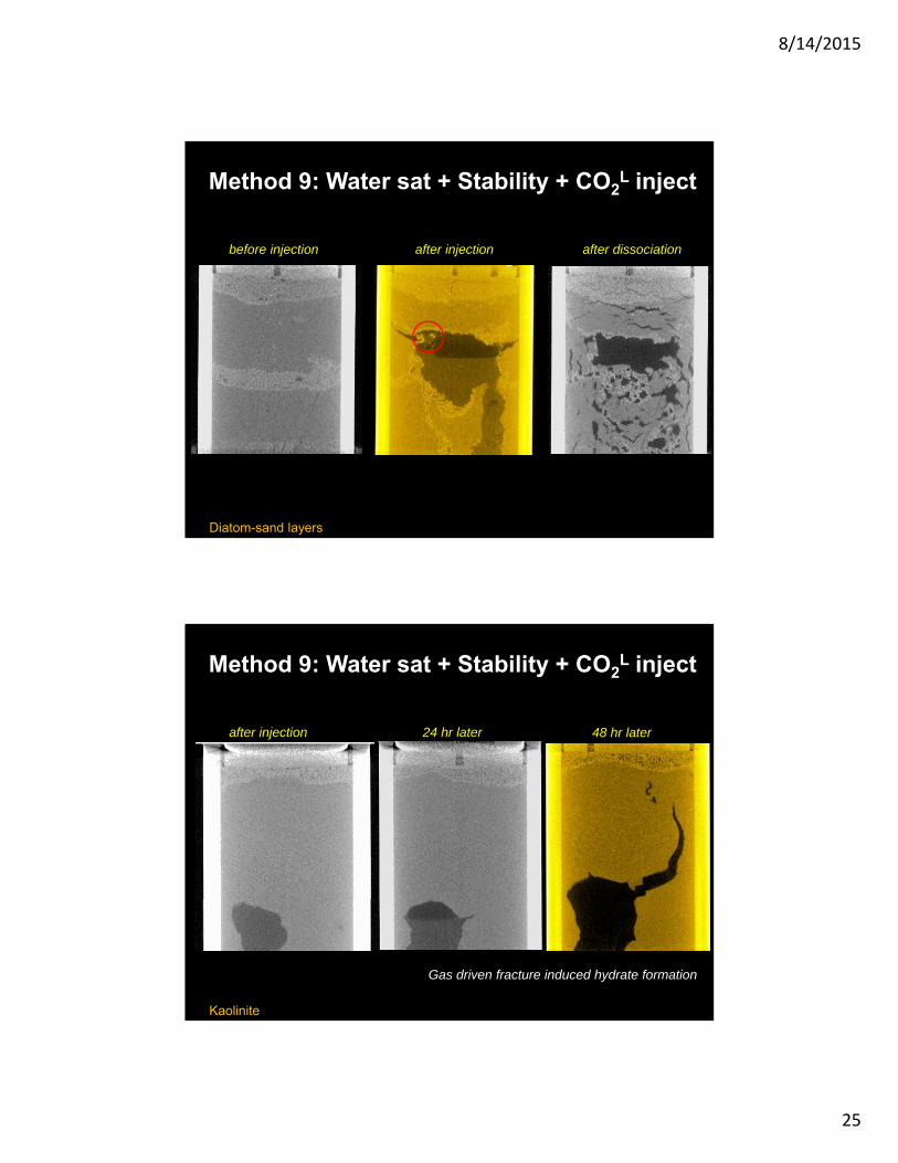
Slide 49
Method 9: Water sat + Stability + CO2L inject
before injection after injection after dissociation
Diatom-sand layers
Slide 50
Kaolinite
Method 9: Water sat + Stability + CO2L inject
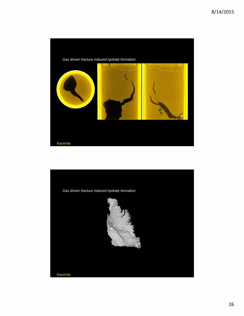
Gas driven fracture induced hydrate formation
after injection 24 hr later 48 hr later
8/14/2015
26
Slide 51
Gas driven fracture induced hydrate formation
Kaolinite
Slide 52
Gas driven fracture induced hydrate formation
Kaolinite
8/14/2015
27
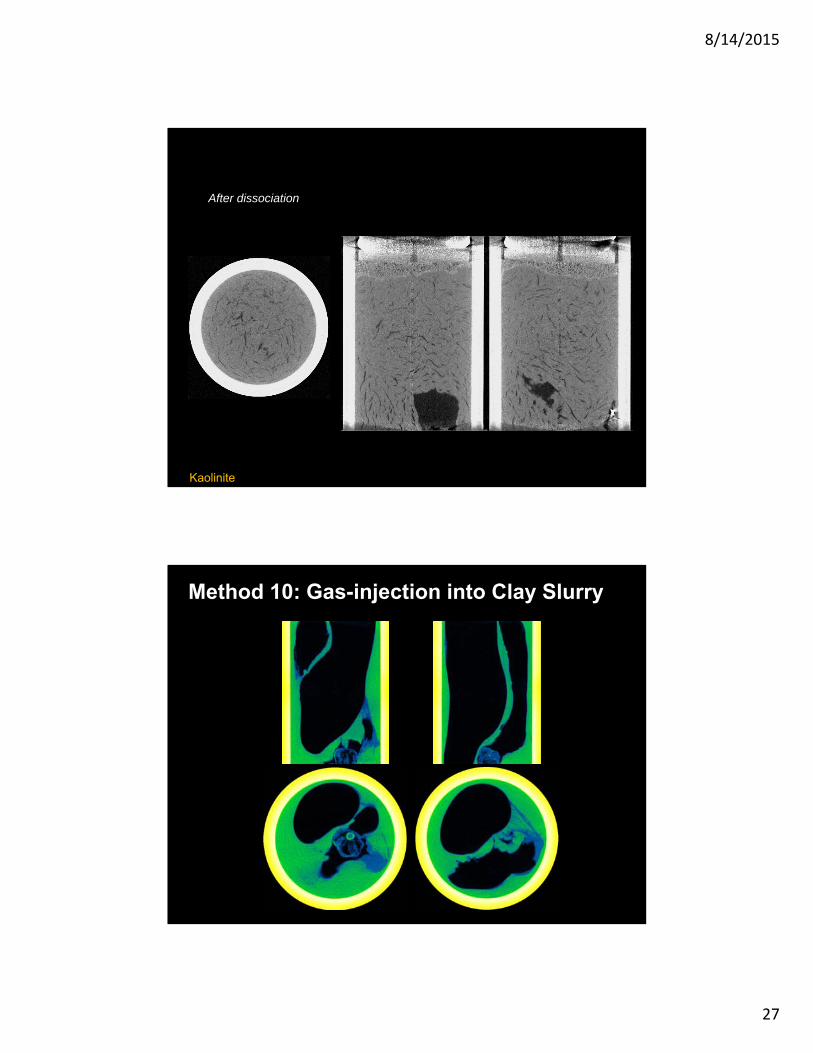
Slide 53
After dissociation
Kaolinite
Slide 54
Method 10: Gas-injection into Clay Slurry
8/14/2015
28
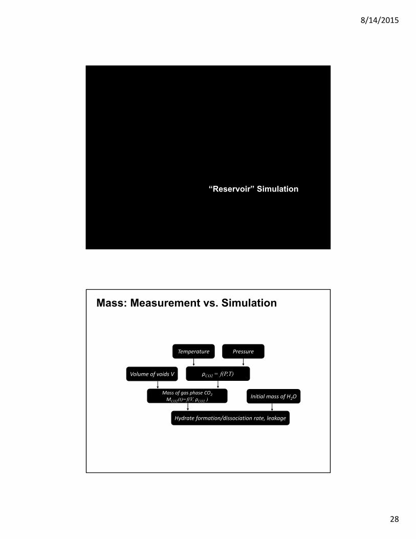
“Reservoir” Simulation
Mass: Measurement vs. Simulation
ρCO2 = f(P,T)
Temperature Pressure
Volume of voids V
Mass of gas phase CO2
MCO2(t)=f(V, ρCO2 ) Initial mass of H2O
Hydrate formation/dissociation rate, leakage
8/14/2015
29
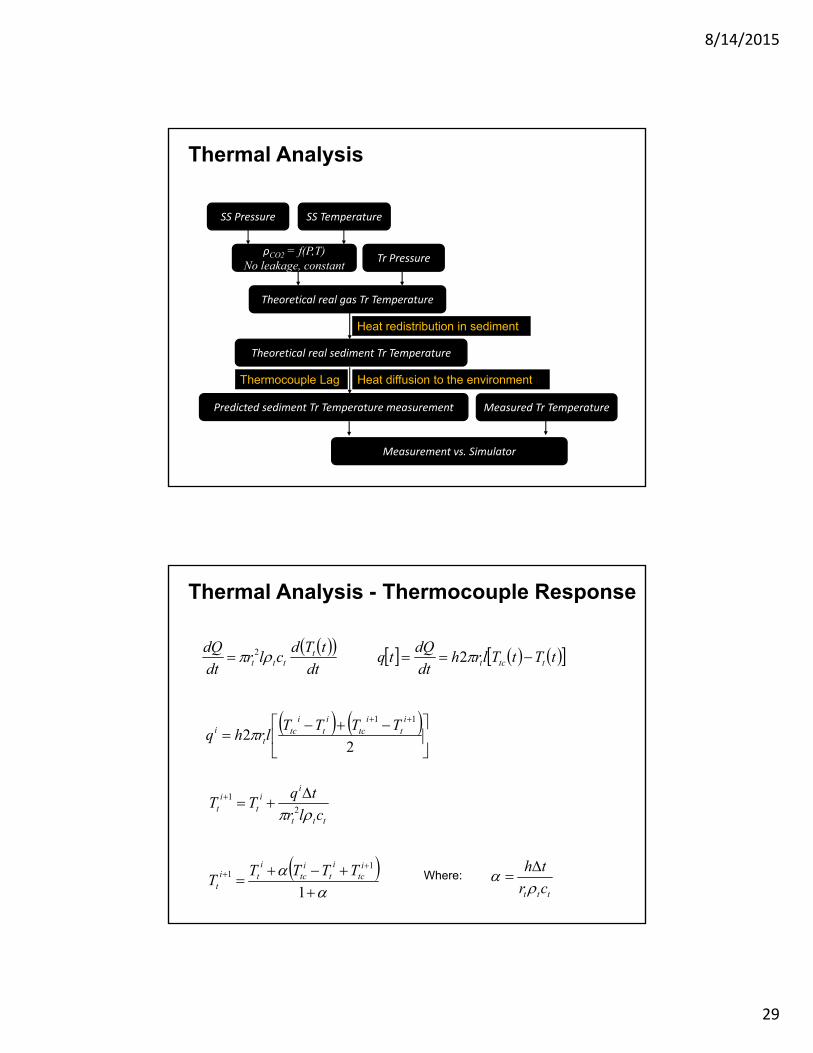
Thermal Analysis
SS TemperatureSS Pressure
ρCO2 = f(P,T)No leakage, constant
Tr Pressure
Theoretical real gas Tr Temperature
Measured Tr Temperature
Measurement vs. Simulator
Heat redistribution in sediment
Theoretical real sediment Tr Temperature
Heat diffusion to the environmentThermocouple Lag
Predicted sediment Tr Temperature measurement
dt
tTdclr
dt
dQ tttt 2 tTtTlrh
dt
dQtq ttct 2
22
11 it
itc
it
itc
ti TTTT
lrhq
ttt
ii
ti
t clr
tqTT
2
1
1
11
itc
it
itc
iti
t
TTTTT Where:
ttt cr
th
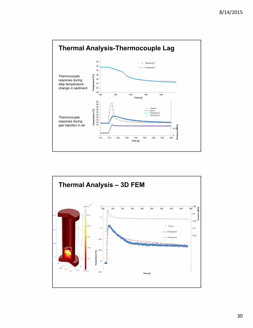
Thermal Analysis - Thermocouple Response
8/14/2015
30
20
22
24
26
28
30
32
34
160 162 164 166 168 170T
emp
erat
ure
[°C
]
Time [s]
Measured T
Predicted T
0
0.5
1
1.5
2
2.5
05
101520253035404550556065
710 715 720 725 730 735 740 745 750
Pre
ssu
re [
MP
a]Tem
per
atu
re [
°C]
Time [s]
Temp 1Gas TPredicted TPressure In
Thermocouple response during step temperature change in sediment
Thermocouple response during gas injection in air
Thermal Analysis-Thermocouple Lag
Thermal Analysis – 3D FEM
2
2.05
2.1
2.15
2.2
2.25
2.3
2.35
2.4
2.45
-4.2
-4
-3.8
-3.6
-3.4
-3.2
-3285 305 325 345 365 385 405 425 445 465
Pre
ssu
re [
MP
a]
Te
mp
era
ture
[°C
]
Time [s]
Temp 1
Predicted T
Pressure In
8/14/2015
31
Physical properties
(additional information: see 2014 End of Year Report)
Properties - Needs
- Borehole stability- Seafloor subsidence- Slope stability / Submarine landslides
Mechanical
- Reservoir modeling- Production enhancement
Thermal
- Hydraulic fracturing- Water production
Hydraulic
- Saturation estimations- Fracture tomography
Electrical
8/14/2015
32
nm µm mm m km
ky
By
My
1 yr
9 hr
s
ms
µs
ns
27 o
rder
s of
mag
nitu
de
16 orders of magnitude
1000 km
CH4 Reservoirs
ps
Å
MD
nano-pores GEO-PLUMBING wells fractures
Laboratory
Borehole logging
Micro organ.
Pore-scale simulators
Mol
ecul
ar ti
me
geol
ogic
tim
e 100m
1m
0.1m
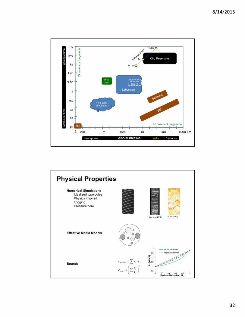
Physical Properties
Numerical SimulationsIdealized topologiesPhysics inspiredLogging Pressure core
Effective Media Models
Bounds
(Lee et al. 2013) (Cook 2010)
Hydrate Saturation, Sh
k T[W
/mK
]
0.5
1
1.5
2
2.5
3
0 0.2 0.4 0.6 0.8 1
Series & Parallel
Hashin-Shtrikman
1
i
iseries
iiparallel
k
xk
kxk
1
2
1
1
2
2
1
1
2
8/14/2015
33
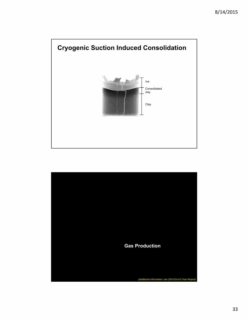
Cryogenic Suction Induced Consolidation
Ice
Clay
Consolidated clay
Gas Production
(additional information: see 2014 End of Year Report)
8/14/2015
34
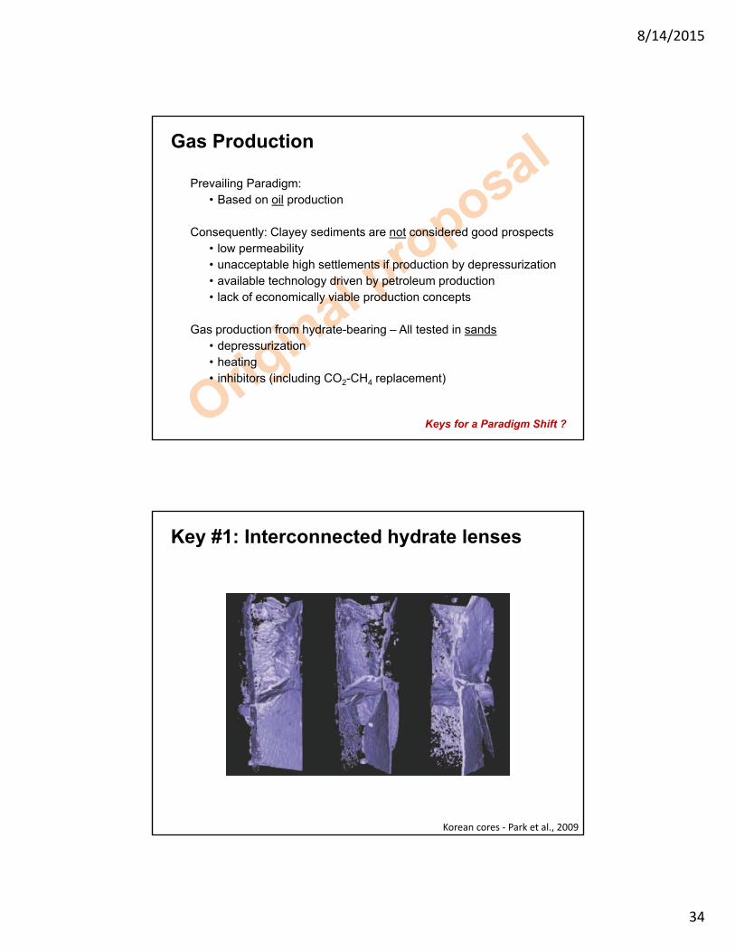
Gas Production
Prevailing Paradigm: • Based on oil production
Consequently: Clayey sediments are not considered good prospects • low permeability• unacceptable high settlements if production by depressurization• available technology driven by petroleum production• lack of economically viable production concepts
Gas production from hydrate-bearing – All tested in sands• depressurization• heating• inhibitors (including CO2-CH4 replacement)
Keys for a Paradigm Shift ?
Key #1: Interconnected hydrate lenses
Korean cores ‐ Park et al., 2009
8/14/2015
35
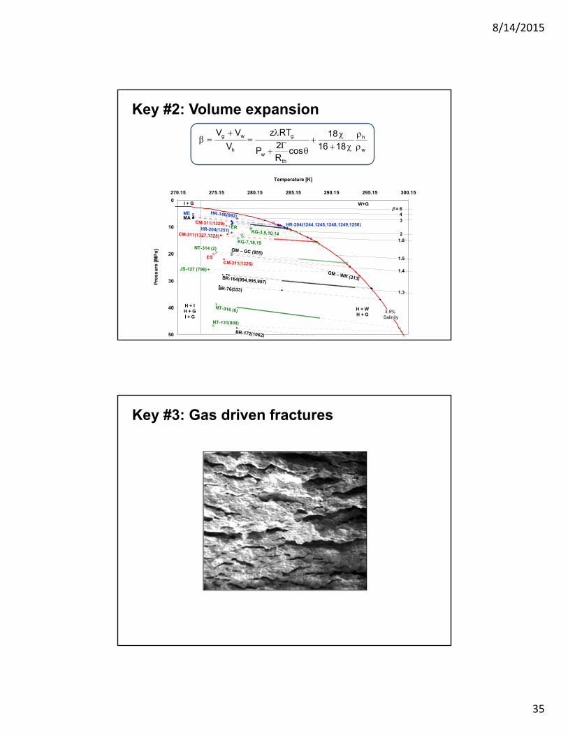
Key #2: Volume expansion
w
h
thw
g
h
wg
1816
18
cosR2
P
RTz
V
VV
0
10
20
30
40
50
270.15 275.15 280.15 285.15 290.15 295.15 300.15
Temperature [K]
Pre
ss
ure
[M
Pa
]
NT-316 (6)
W+G
H + WH + G
H + IH + GI + G
I + G
NT-131(808)
BR-172(1062)
BR-76(533)
BR-164(994,995,997)
CM-311(1325)
ES
NT-314 (2)
KG-7,18,19
CM-311(1327,1328)
HR-204(1251)
GM – WR (313)
KG-3,5,10,14
HR-204(1244,1245,1248,1249,1250)
HR-146(892)MAME
CM-311(1329)ER
JS-127 (796)
β = 6
1.4
1.5
34
1.3
21.8
3.5%Salinity
GM – GC (955)
Key #3: Gas driven fractures
8/14/2015
36
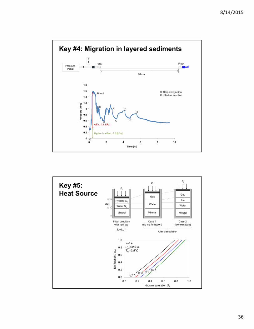
Key #4: Migration in layered sediments
0
0.2
0.4
0.6
0.8
1
1.2
1.4
1.6
1.8
0 2 4 6 8 10
Pre
ss
ure
[kP
a]
Time [hr]
X
O
O O O
XX
X
AEV: 1.3 [kPa]
Hydraulic effect: 0.3 [kPa]
Air out X: Stop air injectionO: Start air injection
90 cm
Filter Filter
PT
Pressure Panel
0.0
0.2
0.4
0.6
0.8
1.0
0.0 0.2 0.4 0.6 0.8 1.0
Hydrate saturation S h
Ice
fra
ctio
n F
Rw
i
(a)
(b)
Mineral
Water Sw
Hydrate Sh
Pi
Mineral
Water
Gas
Pf
Mineral
Water
Gas
Pf
Ice
Case 1(no ice formation)
Case 2(Ice formation)
Initial conditionwith hydrate
After dissociation
VT
nVT
Sh+Sw=1
Ti=5°C
n=0.4
10°C15°C
20°C
Peq=3MPaTeq=2.5°C
Key #5: Heat Source
8/14/2015
37
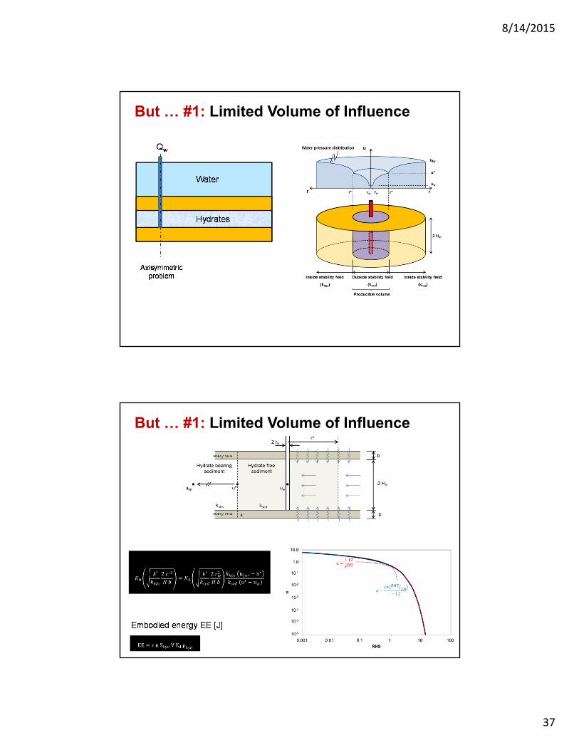
But … #1: Limited Volume of Influence
But … #1: Limited Volume of Influence
8/14/2015
38
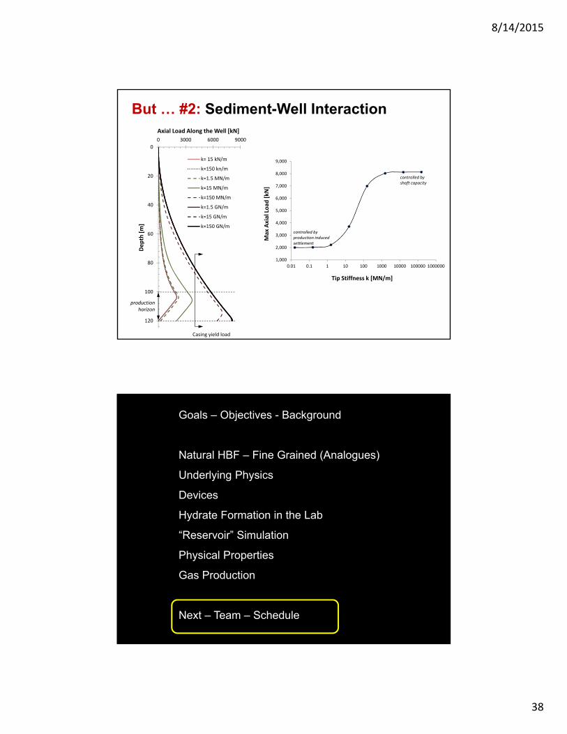
0
20
40
60
80
100
120
0 3000 6000 9000Dep
th [m
]Axial Load Along the Well [kN]
k= 15 kN/m
k=150 kn/m
k=1.5 MN/m
k=15 MN/m
k=150 MN/m
k=1.5 GN/m
k=15 GN/m
k=150 GN/m
1,000
2,000
3,000
4,000
5,000
6,000
7,000
8,000
9,000
0.01 0.1 1 10 100 1000 10000 100000 1000000Max Axial Loa
d [kN]
Tip Stiffness k [MN/m]
controlled by shaft capacity
controlled by production induced settlement
production horizon
Casing yield load
But … #2: Sediment-Well Interaction
L Goals – Objectives - Background
Natural HBF – Fine Grained (Analogues)
Underlying Physics
Devices
Hydrate Formation in the Lab
“Reservoir” Simulation
Physical Properties
Gas Production
Next – Team – Schedule
8/14/2015
39
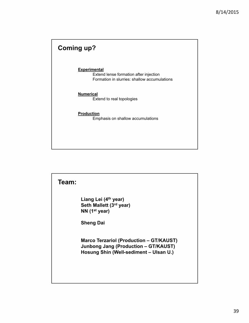
Coming up?
ExperimentalExtend lense formation after injectionFormation in slurries: shallow accumulations
NumericalExtend to real topologies
ProductionEmphasis on shallow accumulations
Team:
Liang Lei (4th year)Seth Mallett (3rd year)NN (1st year)
Sheng Dai
Marco Terzariol (Production – GT/KAUST)Junbong Jang (Production – GT/KAUST)Hosung Shin (Well-sediment – Ulsan U.)
8/14/2015
40
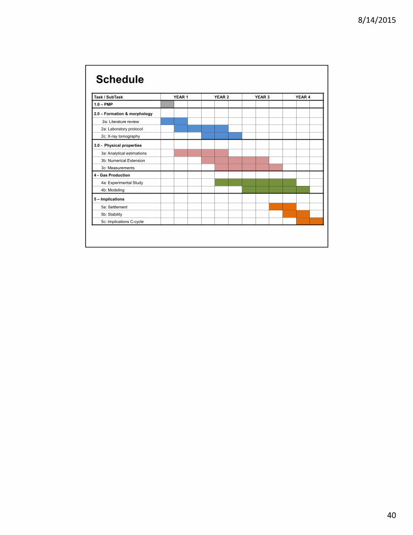
Schedule
Task / SubTask YEAR 1 YEAR 2 YEAR 3 YEAR 4
1.0 – PMP
2.0 – Formation & morphology
2a: Literature review
2a: Laboratory protocol
2c: X-ray tomography
3.0 - Physical properties
3a: Analytical estimations
3b: Numerical Extension
3c: Measurements
4 - Gas Production
4a: Experimental Study
4b: Modeling
5 – Implications
5a: Settlement
5b: Stability
5c: Implications C-cycle
4
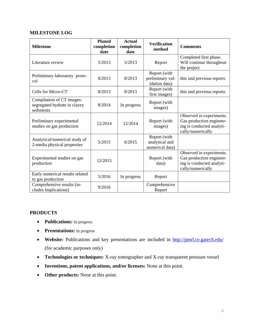
MILESTONE LOG
Milestone Planed
completion date
Actual completion
date
Verification method
Comments
Literature review 5/2013 5/2013 Report Completed first phase. Will continue throughout the project
Preliminary laboratory proto-col
8/2013 8/2013 Report (with
preliminary val-idation data)
this and previous reports
Cells for Micro-CT 8/2013 8/2013 Report (with first images)
this and previous reports
Compilation of CT images: segregated hydrate in clayey sediments
8/2014 In progress Report (with
images)
Preliminary experimental studies on gas production
12/2014 12/2014 Report (with
images)
Observed in experiments. Gas production engineer-ing is conducted analyti-cally/numerically
Analytical/numerical study of 2-media physical properties
5/2015 6/2015 Report (with analytical and
numerical data)
Experimental studies on gas production
12/2015 Report (with
data)
Observed in experiments. Gas production engineer-ing is conducted analyti-cally/numerically
Early numerical results related to gas production
5/2016 In progress Report
Comprehensive results (in-cludes Implications)
9/2016 Comprehensive
Report
PRODUCTS
Publications: In progress
Presentations: In progress
Website: Publications and key presentations are included in http://pmrl.ce.gatech.edu/
(for academic purposes only)
Technologies or techniques: X-ray tomographer and X-ray transparent pressure vessel
Inventions, patent applications, and/or licenses: None at this point.
Other products: None at this point.
5
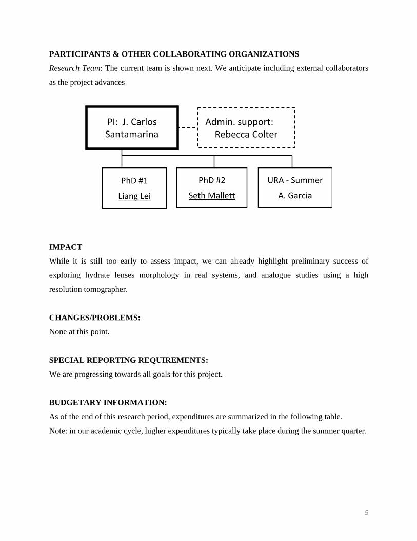
PARTICIPANTS & OTHER COLLABORATING ORGANIZATIONS
Research Team: The current team is shown next. We anticipate including external collaborators
as the project advances
PhD #1
Liang Lei
PhD #2
Seth Mallett
Admin. support:Rebecca Colter
PI: J. Carlos Santamarina
URA ‐ Summer
A. Garcia
IMPACT
While it is still too early to assess impact, we can already highlight preliminary success of
exploring hydrate lenses morphology in real systems, and analogue studies using a high
resolution tomographer.
CHANGES/PROBLEMS:
None at this point.
SPECIAL REPORTING REQUIREMENTS:
We are progressing towards all goals for this project.
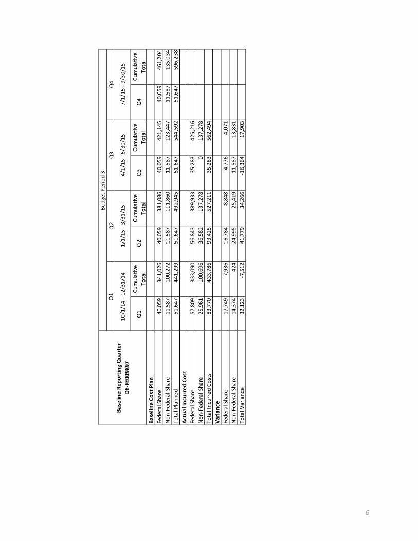
BUDGETARY INFORMATION:
As of the end of this research period, expenditures are summarized in the following table.
Note: in our academic cycle, higher expenditures typically take place during the summer quarter.
6
Baseline Co
st Plan
Federal Share
Non‐Federal Share
Total Planned
Actual In
curred
Cost
Federal Share
Non‐Federal Share
Total Incurred Costs
Varia
nce
Federal Share
Non‐Federal Share
Total Variance
Baseline Re
porting Qua
rter
DE‐FE009897
Q1
Cumulative
Total
Q2
Cumulative
Total
Q3
Cumulative
Total
Q4
Cumulative
Total
40,059
341,026
40,059
381,086
40,059
421,145
40,059
461,204
11,587
100,272
11,587
111,860
11,587
123,447
11,587
135,034
51,647
441,299
51,647
492,945
51,647
544,592
51,647
596,238
57,809
333,090
56,843
389,933
35,283
425,216
25,961
100,696
36,582
137,278
0137,278
83,770
433,786
93,425
527,211
35,283
562,494
17,749
‐7,936
16,784
8,848
‐4,776
4,071
14,374
424
24,995
25,419
‐11,587
13,831
32,123
‐7,512
41,779
34,266
‐16,364
17,903
Budget Period 3
Q1
Q2
Q3
Q4
1/1/15 ‐ 3/31/15
4/1/15 ‐ 6/30/15
7/1/15 ‐ 9/30/15
10/1/14 ‐ 12/31/14
7
National Energy Technology Laboratory 626 Cochrans Mill Road P.O. Box 10940 Pittsburgh, PA 15236-0940 3610 Collins Ferry Road P.O. Box 880 Morgantown, WV 26507-0880 13131 Dairy Ashford Road, Suite 225 Sugar Land, TX 77478 1450 Queen Avenue SW Albany, OR 97321-2198 Arctic Energy Office 420 L Street, Suite 305 Anchorage, AK 99501 Visit the NETL website at: www.netl.doe.gov Customer Service Line: 1-800-553-7681