Embed Size (px)
Citation preview

1
Oil & Natural Gas Technology
DOE Award No.: DE- FE0010141
Quarterly Research Performance Progress Report
(Period ending 6/30/2014)
Submitted August 14, 2014
Temporal Characterization of Hydrates System Dynamics beneath Seafloor Mounds: Integrating Time-Lapse Electrical Resistivity Methods and In Situ
Observations of Multiple Oceanographic Parameters
Project Period: October 1, 2012 – October 31, 2015
Submitted by: Carol Blanton Lutken
The University of Mississippi Mississippi Mineral Resources Institute and
Center for Marine Resources and Environmental Technology, DUNS # 067713560.
111 Brevard Hall University, Mississippi, 38677
e-mail: [email protected] Phone number: 662-915-7320/5598; 662-202-8485
Prepared for:
The Department of Energy - Methane Hydrates Program
United States Department of Energy National Energy Technology Laboratory
Office of Fossil Energy

2
RESEARCH PERFORMANCE PROGRESS REPORT
Temporal Characterization of Hydrates System Dynamics beneath Seafloor Mounds: Integrating Time-Lapse Electrical Resistivity Methods and In Situ
Observations of Multiple Oceanographic Parameters
ACCOMPLISHMENTS: Major objectives of the project are to: 1) characterize, geophysically, the sub-bottom distribution of hydrate and its temporal variability and, 2) contemporaneously record relevant environmental parameters (temperature, pressure, salinity, turbidity, bottom currents and seafloor microseismicity) to investigate possible links of the variability to climate. In order to achieve these overall objectives, we have identified the following goals: a) employ the Direct Current Resistivity (DCR) method as a geophysical indicator of hydrates, b) identify hydrate formation mechanisms in seafloor mounds, c) detect short-term changes within the hydrates system, d) illuminate relationships/impacts of local oceanographic and microseismic parameters on the hydrates
system and, indirectly, the benthic fauna, e) monitor fluid/hydrate motion and seafloor instability that these changes might produce. Accomplishments achieved in relation to these goals include the following (Quarter 1):
• Completion and acceptance of the Project Management Plan; successful “kick-off,” • Successful completion and testing (at sea) of the I-SPIDER (patent pending), a new deployment
and surveying system, • Beginning of the assembly and evaluation of existing data from the research site at MC118, • Renovation of the Direct Current Resistivity (DCR) cable in preparation for the September
survey.
Accomplishments achieved in relation to these goals include the following (Quarter 2): • We have used the I-SPIDER, the Integrated Scientific Platform for Instrument Deployment and
Emergency Recovery, successfully on three successive cruises both surveying and deploying instruments;
• CMRET’s shop and SDI’s shop have coordinated effort to build the communications software that will enable us to have live communication with the DCR array while in survey mode;
• We have completed the consolidation of electronics into a single “topside system” that greatly increases our ability to control and monitor at-sea operations;
• We have installed Ultra-short Baseline (USBL) transponders in the hull of the R/V Pelican to maintain our exceptional navigation/locating capabilities while at sea;
• We have made significant progress in processing the 2013 multibeam data from MC118; • We have established a processing protocol for the new polarity-preserving chirp data from
MC118; • We have begun to build the Integrated Portable Seafloor Observatory (IPSO) lander; • We have made repairs to the damaged resistivity system resulting from the flooding event,
summer 2012; • We have determined what caused the instrument to flood;

3
• We have devised a solution to the flooding problem; • We have begun work to devise a means whereby operation of the array can be accomplished
autonomously while on the seafloor; • We have scheduled two cruises for 2014 on the R/V Pelican: April 7-12 and October 3-6.
Accomplishments achieved in relation to project goals include the following (Quarter 3):
• We have completed the survey-mode communications electronics; • We have upgraded the SSD and I-SPIDER individually and as a tandem system; • We have selected primary and secondary target sites for the DCR survey and have plotted the
survey; • We have built the IPSO lander frame, researched and ordered instruments and installed them
on the IPSO lander; • We have begun processing the new polarity-preserved chirp data from MC118; • We have completed repairs to the seafloor DCR system associated with the housing flooding
that occurred in July 2012; • SDI replaced the power and control though-housing connector to the DCR instrument with one
that has higher current capacity; • We have devised a system whereby the DCR system will be controlled remotely while on the
seafloor; • SDI built the Atom control computer and installed it in a pressure housing; • We have developed/acquired new control software for autonomous operation of the DCR
instrument; • We have built a stand that will hold the DCR instrument electronics and housing end-cap in an
inverted position while assembling the DCR housing. Accomplishments achieved in relation to project goals include the following (Quarter 4):
• We have inventoried data from MC118 that has and will continue to inform our survey and deployment strategies;
• We have established a processing protocol for the polarity-preserving chirp data from MC118; • We have designed and begun acquiring components for the replacement battery system for the
IPSO; • We have completed a paper describing the new resistivity data processing method that will be
used to process the targeting data as a 3D data set; • We have developed a data acquisition and communication and control system to allow long
term deployment of a DC resistivity array on the sea floor; • We have submitted a no-cost extension request to complete Year 1 work that has been
approved. Accomplishments achieved in relation to project goals include the following (Quarter 5):
• We have completed the electronics integration for command and control throughout survey and deployment/monitoring modes;
• We have tested the joint operation of the IDP, the control computer, and the resistivity instrument in the remote-control and autonomous monitoring mode of operation;
• We have built/modified a deployment system for the 1000m long DCR array; • We have a plan for processing initial reconnaissance DCR data; • We have a plan in place for the cruise to collect survey data and to place the DCR array and
lander for a 6-month data-collecting period.

4
Accomplishments achieved in relation to project goals include the following (Quarter 6):
• We completed the construction and assembly and installation of sensors for the IPSO; • We planned and conducted a successful cruise to MC118, April 9-12; • We have made an experimental and successful use of a new/modified deployment system for
the 1000m long DCR array; • We collected four ~1km-long resistivity profiles in survey mode; • We completed initial analyses of the survey lines; • We selected the monitoring site, adapted the lander for monitoring mode, and deployed the
IPSO-DCR assembly at the monitoring target; • We successfully executed the continuation presentation; • We have a No-Cost Extension in place; • We have reprocessed initial survey data with a variety of filters.
We completed the construction and assembly and installation of sensors for the IPSO. The seafloor lander used in this project has three electronics devices onboard, each contained in its own pressure housing. The first device is the Integrated Data Power Unit (IDP), which is low-power timer/controller, that can be programmed to turn the power to other instruments on and off on a set schedule and manages communications with the surface vessel via fiber optic link in the tow cable, if present, or an acoustic modem. The IDP is adjusted, manually, to either survey or monitoring mode. The second device is a low-power Atom computer that provides instructional control of the resistivity instrument. The third device is the seafloor resistivity instrument itself, which also contains a computer to manage the details of resistivity data collection. Sensors actually housed within the lander for data-collection during monitoring mode include an acoustic doppler current profiler (ADCP) to collect current information, a conductivity-temperature-depth (CTD) instrument, and a turbidity meter. These instruments have internal data-loggers and batteries. A battery system on the IPSO powers the DCR instrument and computers. We planned and conducted a successful cruise to MC118, April 9-12. Dates scheduled for the cruise were April 7-12. Due to extremely rough weather in the Gulf of Mexico through April 8, we delayed the start of the cruise until we had a reasonable prospect of success, especially for surveying. When we arrived onsight, we assessed the sea state and conditions and continued to monitor the forecasts closely. We were able to collect 4 very good survey lines over Woolsey Mound before the weather forced us to make a decision regarding the 6-month monitoring deployment. However, the adaptation of the computer systems and addition of oceanographic sensors to the IPSO were made and the deployment was accomplished April 11, ahead of deteriorating weather conditions. We have made an experimental and successful use of a new/modified deployment system for the 1000m long DCR array. During previous experiences with long arrays, we have deployed the systems manually. For this deployment of the 1000m long DCR array, we devised an alternative to this lengthy and very tiring method that makes use of a wide-angle shiv. The array is configured so that the nodes are narrow, tapered at both ends, and well-taped to preclude catching on the cable or within the shiv. This system is designed to make a quicker, less dangerous deployment. Spooling the array onto the Dynacon winch (Figure 1) was slow and challenging but successful. Deploying the array through the wide angle shiv was also successful though the nodes were a close fit and deployment was, necessarily, slow.

5
Figure 1. Spooling the 1100m Direct Current Resistivity Array onto the Pelican’s Dynacon winch for deployment in survey/reconnaissance mode. Note nodes wrapped in grey tape.
We have collected four ~1km-long resistivity profiles in survey mode. Target survey lines had been selected prior to the survey but with the knowledge that we would not be able to make final decisions until we were onsight. Although restricted by fairly strong – and eventually shifting – winds, we were able to run four lines over many of the subbottom targets identified in the chirp data (Figure 2). Initially, the lander was used in reconnaissance profiling mode, controlled remotely by an operator on

6
the surface vessel, to collect a series of resistivity profiles to inform the selection of a profile to be monitored over the initial 6-month monitoring period. In this remote-control mode, the I-SPIDER (Integrated Scientific Platform for Instrument Deployment and Emergency Recovery, patent pending) ROV (remotely Operated Vehicle) was attached to the lander, to provide live video feed from the bottom and real-time positioning data for navigating the instrument package. Two-way communication between the operator at a workstation on the surface vessel and the seafloor resistivity instrument was transmitted through a fiber optic link within the tow cable to the I-SPIDER, through the IDP, which transmits to the resistivity instrument as RS232 instructions. In this way, the operator can instruct the instrument which acquisition parameters to use during data collection, when to start taking data, monitor the quality of the data as they are collected, and retrieve the data from the seafloor instrument after the data acquisition is complete. One potential problem in this mode of operations is the chance that the communication link between the resistivity instrument and the shipboard workstation will hang. In this situation, one of the devices operates as if communication is still on-going, while the other operates as if it has been terminated. If this happens, there is no mechanism to restore two-way communication using commands sent through the fiber optic link. For this possibility, an acoustic modem option was added, such that the IDP could be signaled from the surface vessel by the acoustic modem to cycle the power to the resistivity instrument, causing it to re-boot. This would allow communication through the fiber optic link to be re-established.
Figure 2. Four survey/reconnaissance profiles were collected along the traces shown in black. The IPSO lander and attached DCR array were eventually deployed at the location shown in red. This deployment line lies along a fault and the sites where bubble plumes have been observed at the seafloor and hydrates recovered (via gravity cores) from the shallow subsurface.

7
We completed initial analyses of the survey lines. The profiles collected during reconnaissance mode were examined and used to select the target site for long-term monitoring. Analyses were accomplished onboard by Xu and Dunbar to determine 1) if the data we were collecting were adequate to answer the scientific questions we were asking, 2) if we needed to make adjustments to the collecting parameters prior to long-term deployment, and 3) to recover data to inform our decision on the site to monitor. These profiles (Figure 3) were processed in real time, as the electrode array was being repositioned for the next profile. The data were of sufficient quality to satisfy all three criteria.
Figure 3. Inverted resistivity sections. Initial processing of DCR profiles collected across Woolsey Mound, MC118 in April, 2014, shown in Figure 2. Data inversion was performed after removing data using statistical filtering tool within the AGI inversion. We selected the monitoring site, adapted the lander for monitoring mode, and deployed the IPSO-DCR assembly at the monitoring target. This task was the primary mission of the entire project up to this point. Once the reconnaissance resistivity data were collected, processed, and a suitable profile selected for long-term monitoring, we brought the I-SPIDER and lander back onto the ship, reconfigured the lander to operate in the autonomous monitoring mode without the I-SPIDER but with the addition of the oceanographic parameters sensors/instruments. In this mode, the IDP is programmed to turn power on to the control computer and the resistivity instrument at a set interval - once per week - and leave the power on for a set time, three hours. Both the control computer and resistivity instrument are set to boot automatically when they receive power. The resistivity instrument boots and waits for instructions. The control computer boots and automatically executes a control program written to

8
perform the monitoring task. Each time the control program runs, it first establishes RS232 communication with the resistivity instrument. Then it downloads any data files left on the resistivity instrument to the larger solid state control computers. Once the data are retrieved, the control program erases the data from the resistivity instrument to make room for the new data set. The control program then transmits a set of measurement instructions to the resistivity instrument and tells it to start data collection. Once data collection on the resistivity instrument is initiated, the job of the control computer is complete, so the control program initiates the shutdown of Windows. The resistivity instrument continues to collect data until its command set has been completed and then it waits for further instructions. In this mode there is not a mechanism for the resistivity instrument to signal the IDP or control computer that it has completed data acquisition. Instead, the IDP is programmed to leave the power on to instrument for approximately twice the time required to collect the data and then to shut it down. This sequence will repeat until battery power is insufficient for it to continue, estimated to be 30 cycles. The site we selected to monitor lies precariously close to crater complexes and faults. Based upon the ability of the ship’s crew and our deck crew to complete the meticulous work required for deployment, we believed we could “thread the needle” between the hazards. Adapting the lander and the electronics for monitoring mode was accomplished in several hours on-deck. The actual deployment was made in building seas but with a steady wind out of the east. Although we had hoped to deploy the lander to the west of the crater complex, steaming into the wind gave the most predictable prospects of success so we chose that route, deploying the array W to E across the northern portions of Woolsey Mound right through the NW crater complex (Line 5, Figure 2). Our deployment was successful. Whether or not we recover data, however, will remain unknown until our return in fall, 2014. We successfully executed the continuation presentation. DOE arranged for our group to make a continuation presentation to the Methane Hydrates group at NETL, April 16, 2014. This presentation went quite well with acute interest centering about the resistivity profiles generated during the survey mode component of the cruise. It is our intention to augment the “loose” survey we recovered in April with additional survey lines when we return to the site in the fall. We have a No-Cost Extension in place. Immediately following the successful conclusion of the continuation presentation, we began work on the no-cost extension that will enable our work to continue into the early part of 2016. This extension will include no additional funds but will allow us additional time to execute the cruise/data-collection portions of the project. We have reprocessed initial survey data with a variety of filters. Dunbar and Xu have spent considerable time processing the survey data applying a variety of different filters. This process is designed to find the optimal data filter, one that will remove noise and extraneous data points without removing legitimate data. Some of these efforts appear in Figures 4 and 5.

9
Figure 4. Re-processing of DCR profiles after statistical data filtering. Data inversion was performed after removing noisy data from each profile independently, using a statistical filtering tool built into the EarthImager2D™ inversion program by AGI, Inc.
Figure 5. Reprocessing of DCR profiles after manual data filtering. Data inversion was performed after removing noisy data from each profile by manually editing each profile independently.

10
MILESTONE CHART:
Milestones A, B, C and D are complete; Milestone E cannot be completed until the first Year 2 cruise sails.
Milestone Planned Completion
Actual Completion
Verification Method Progress/Deviation from Plan
Milestone A: Target sites selection for IPSO deployment at MC118
9/15/2013 9/17/2013 4 targets identified 2 days
Milestone B: Successful testing of the DCR cable in a pressure-testing facility – SW Research Institute or comparable.
9/15/2013 9/11/2013 Successful test of the DCR system at 1000m water depth equivalent
Milestone C: Successful testing of a new Integrated Portable Seafloor Observatory (IPSO).
9/15/2013 9/25/2013 Successful onshore test of IPSO
10 days
Milestone D: Successful deployment of Integrated Portable Seafloor Observatory (IPSO).
4/30/2014 4/12/2014 Proper orientation and functioning of IPSO
Milestone E: Recover data from MC118 with the IPSO
10/31/2014 IPSO recovered with data
Milestone F: Recover data from MC118 with the IPSO
4/30/2015 IPSO recovered with data
Milestone G: Complete analysis of temporal characterization of hydrates system dynamics at MC118
10/31/2015 Resistivity and temporal data produce reasonable temporal analysis
Milestone H: Complete final report and submit to DOE
1/31/2016 Report accepted by COR
PRODUCTS: A new lander, the IPSO; oceanographic instruments for the IPSO; A new cable-deployment system for the DCR; Command and control hardware and software; A 1100m long DCR cable-array; Cruise report of April’s activities, http://mmri.olemiss.edu/Home/Publications/Cruise.aspx; Raw and processed resistivity data from a hydrates mound. PARTICIPANTS & OTHER COLLABORATING ORGANIZATIONS: During this quarter, personnel from the University of Mississippi and from both subcontracting organizations participated in the project, including the cruise. Their contributions are as follows: Name: Carol Lutken Project Role: PI, University of Mississippi Nearest person month worked: 1 (6 weeks)

11
Contribution to Project: Lutken executed all communications between participants and with DOE and LUMCON and made arrangements for the April, 2014 cruise. She worked with the MMRI shop to assure everyone’s readiness for the April cruise, filed the Request to conduct research with the Bureau of Ocean Energy Management, and the pre- and post-cruise reports with LUMCON. She served as Chief Scientist on the cruise making her responsible for the successes and failures of the mission. She is responsible for the cruise report. She continues to work with D’Emidio to analyze subsurface data available from MC118. She compiled information for and wrote the quarterly progress report. She organized and participated in the continuation presentation and submitted the paperwork for the NCE. Name: Marco D’Emidio Project Role: Scientist, University of Mississippi Nearest person month worked: 1 (3 weeks) Contribution to Project: D’Emidio worked to assure all electronics and computing components were functional, up-to-date and ready to go on the April cruise. This included making backup copies of all data relevant to the cruise and data-collecting efforts. He continues to work with the ppchirp processing, focusing on the MC118 data. D’Emidio is in charge of cruise navigation, tracking all components during survey mode and logging locations and dispositions of equipment on the seafloor. He also generates visuals for cruise navigation, reports, proposals, etc. Name: Matt Lowe Project Role: Marine Systems Specialist, University of Mississippi Nearest person month worked: 1 (5 weeks) Contribution to Project: Lowe is the Chief of shop operations at MMRI/CMRET. During this quarter, he completed fabrication and replacement of appropriate components for systems necessary for the cruise, collaborated with SDI on electronics integration and compatibility. With Steven and Larry, Matt assures that the MMRI portable shop is fully equipped and that MMRI vehicles that are needed to transport people and equipment to the cruise are in working order and equipped for the trip. He is in charge of all deck operations, making certain that all goes smoothly and safely on the back deck. Together with the Chief Scientist, he makes calls on weather related tasks. He is ultimately in charge of the safety and condition of equipment including our fiber-optic cable that provides communication between the equipment and the support vessel. Name: Steven Tidwell Project Role: Research Associate, University of Mississippi Nearest person month worked: 1 (4 weeks) Contribution to Project: Tidwell is the MMRI/CMRET shop research associate with a degree in geological engineering and expertise in machining and electronics as well as computer software. During the cruise, Steven is vital on the back deck and can also operate TrakLink. He is training in cable maintenance – terminations and storage. Name: John Dunbar Project Role: Co-I, Baylor University Nearest person month worked: 1 (5 weeks) Contribution to Project: Dunbar and Xu made all preparations for the DCR instrument – cabled array, computer and software – for the cruise. These systems operated nicely throughout the cruise but were also adjusted while underway to insure data quality. Dunbar and Xu spent much time processing data while underway so that we could have all possible information available to make monitoring mode decisions prior to the actual deployment.

12
Name: Tian Xu Project Role: Graduate student, Baylor University Nearest person month worked: 0 (2 weeks) Contribution to Project: Xu works with Dunbar to define the processing of resistivity data collected during survey mode. Although he remains heavily and vitally involved in the project, participated in the cruise and processed data, Xu has been supported by a teaching assistant position this summer so his time has not been charged to the project. Xu is the primary author on a paper resulting from this work and has commenced work on another. He will return to the project full-time in the fall. Name: Paul Higley Project Role: Co-I, Specialty Devices, Inc. Nearest person month worked: 1 (3 week) Contribution to Project: Higley, an ocean engineer works in all aspects of cruise activity. He participated in the cable design and spooling and in the terminations and adaptation of the DCR system from survey to monitoring mode. Designed and executed the systems tests. Name: Scott Sharpe Project Role: Electronics specialist, Specialty Devices, Inc. Nearest person month worked: 1 (4 weeks) Contribution to Project: Sharpe heads the electronics and programming staff at SDI. He redesigned the IDP for this project, programmed and reprogrammed the components for the cruise and for monitoring mode. He developed the data acquisition and communication and control system to allow long term deployment of a DC resistivity array on the sea floor. He participated in the cruise and instructed the SDI technician who assisted during cruise operations. He is responsible for all electronics systems oversight. Name: SDI Technical staff Project Role: Electronics and technical support, Specialty Devices, Inc. Nearest person month worked: 1 (4 weeks) Contribution to Project: Worked with Higley and Sharpe to develop the data acquisition and communication and control system to allow long term deployment of a DC resistivity array on the sea floor. One technician participated in the April cruise both in the tech room and on the back deck. IMPACT: Since the SSD was not available for the April cruise, we adapted the I-SPIDER to perform its functions. This more robust vehicle proved its sturdiness and versatility in both survey and deployment modes. The I-SPIDER towed the DCR array throughout the surveys and even when it encountered the bottom in the shallowest portions of the survey, was not seriously impacted. It was used quite successfully to emplace the lander. Unfortunately, during survey mode, the lander tipped over 3 of 4 deployments. We are working to correct this flaw for the next cruise. The tipping did not seem to affect the quality of resistivity data but it could impact our oceanographic data acquired during monitoring mode. Although the lander did not fall all the way over when deployed for the 6-month term, it was nowhere near to vertical (ideal) and may have tipped over by now. For this and other reasons, we are attempting to secure additional days on a September cruise to recover the lander and array to check on data recovery. This should not result in additional cost to the project as it will be coupled with another job that will cover transit costs. If the recovery is successful and the electronics are functioning correctly, we will continue our surveying and redeploy the IPSO. If repairs are indicated, we will bring the system home,
13
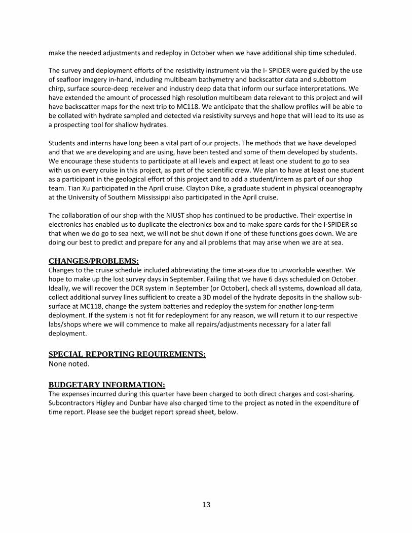
make the needed adjustments and redeploy in October when we have additional ship time scheduled. The survey and deployment efforts of the resistivity instrument via the I- SPIDER were guided by the use of seafloor imagery in-hand, including multibeam bathymetry and backscatter data and subbottom chirp, surface source-deep receiver and industry deep data that inform our surface interpretations. We have extended the amount of processed high resolution multibeam data relevant to this project and will have backscatter maps for the next trip to MC118. We anticipate that the shallow profiles will be able to be collated with hydrate sampled and detected via resistivity surveys and hope that will lead to its use as a prospecting tool for shallow hydrates. Students and interns have long been a vital part of our projects. The methods that we have developed and that we are developing and are using, have been tested and some of them developed by students. We encourage these students to participate at all levels and expect at least one student to go to sea with us on every cruise in this project, as part of the scientific crew. We plan to have at least one student as a participant in the geological effort of this project and to add a student/intern as part of our shop team. Tian Xu participated in the April cruise. Clayton Dike, a graduate student in physical oceanography at the University of Southern Mississippi also participated in the April cruise. The collaboration of our shop with the NIUST shop has continued to be productive. Their expertise in electronics has enabled us to duplicate the electronics box and to make spare cards for the I-SPIDER so that when we do go to sea next, we will not be shut down if one of these functions goes down. We are doing our best to predict and prepare for any and all problems that may arise when we are at sea. CHANGES/PROBLEMS: Changes to the cruise schedule included abbreviating the time at-sea due to unworkable weather. We hope to make up the lost survey days in September. Failing that we have 6 days scheduled on October. Ideally, we will recover the DCR system in September (or October), check all systems, download all data, collect additional survey lines sufficient to create a 3D model of the hydrate deposits in the shallow sub-surface at MC118, change the system batteries and redeploy the system for another long-term deployment. If the system is not fit for redeployment for any reason, we will return it to our respective labs/shops where we will commence to make all repairs/adjustments necessary for a later fall deployment. SPECIAL REPORTING REQUIREMENTS: None noted. BUDGETARY INFORMATION: The expenses incurred during this quarter have been charged to both direct charges and cost-sharing. Subcontractors Higley and Dunbar have also charged time to the project as noted in the expenditure of time report. Please see the budget report spread sheet, below.

Baseline Cost PlanFederal Share 127,121 127,121 127,120 254,241 209,200 463,441 127,120 590,561 - 590,561 105,994 696,555 Non-federal Share 36,912 36,912 36,912 73,824 36,912 110,736 36,912 147,648 - 147,648 28,973 176,621 Total Planned 164,033 164,033 164,032 328,065 246,112 574,177 164,032 738,209 - 738,209 134,967 873,176 Actual Incurred CostFederal Share - - 8,592 8,592 86,331 94,923 201,745 296,668 42,214 338,882 74,615 413,497 Non-federal Share 22,599 22,599 5,770 28,369 12,584 40,953 - 40,953 55,488 96,441 10,843 107,284 Total Planned 22,599 22,599 14,362 36,961 98,915 135,876 201,745 337,621 97,702 435,323 85,458 520,781 VarianceFederal Share 127,121 127,121 118,528 245,649 122,869 368,518 (74,625) 293,893 (42,214) 251,679 31,379 283,058 Non-federal Share 14,313 14,313 31,142 45,455 24,328 69,783 36,912 106,695 (55,488) 51,207 18,130 69,337 Total Planned 141,434 141,434 149,670 291,104 147,197 438,301 (37,713) 400,588 (97,702) 302,886 49,509 352,395
Quarter 4
10/1/13 - 12/31/13
Q4Cumulative
Total Q1
1/1/14 - 3/31/14 4/1/14 - 6/30/14 7/1/14 - 9/30/14 10/1/14 - 12/31/14
Q1Cumulative
Total Q2Cumulative
Total Q3Cumulative
TotalCumulative
Total Q2Cumulative
TotalQ4Cumulative
Total
Budget Period 3Quarter 1 Quarter 2
1/1/15 - 3/31/15 4/1/15 - 6/30/15
Quarter 3
7/1/13 - 9/30/13
Q3Cumulative
TotalQ1 Cumulative Total
1/1/13 - 3/31/13
DOE Hydrates FY12 DE-FE0010141
Baseline Reporting by Quarter
Quarter 1 - Corrected Quarter 2Budget Period 2
Quarter 1 Quarter 2 Quarter 3 Quarter 4Quarter 5
1/1/14 - 3/31/14
Q5Cumulative
Total
Budget Period 1
4/1/13 - 6/30/13
Q2Cumulative
Total