Embed Size (px)
Citation preview


2 OIL ANALYZERS
What is Oil Analysis? • Oil analysis is a chemical and physical
evaluation of a used lubricant.
• As in the analysis of human blood,oil analysis provides insight as to theinternal condition of equipment andthe oil itself.
What Are the Benefitsof Oil Analysis? Oil analysis enables you to:• Obtain optimum equipment life by
preventing premature equipment failure.
• Reduce maintenance costs by reducingunscheduled downtime.
• Identify pending problems before theybecome catastrophic.
• Schedule preventive maintenancewhen it is convenient.
• Calculate optimum drain intervals toreduce lubricant and disposal costs.
• Enable better assessment of equipmentand lubricant performance.
Table of ContentsThe Tools of Oil Analysis...................................3
Oil Sampling Tips / Sampling Frequency .........4
Oil Sampling Methods ......................................5
Reading Your Oil Analysis Report................6 - 7
Diesel and Gasoline Engine Guidelines ............7
Example Report...........................................8 - 9
Elemental Interpretation Guide .......................10
Wear Metals Analysis......................................11
Wear Metal Reference Guides - Engine &Manual Transmission ......................................12
Wear Metal Reference Guides - Automatic Transmission, DifferentialDrive & Industrial Gears ..................................13
Hydraulics & Air Compressors........................14
SAE Engine and Gear Oil Viscosity Grade @100° C & ISO Viscosity Grade @ 40° C...........15
Tips for Completing OAI Information Guide ...16

OIL ANALYZERS 3
The Tools of Oil Analysis
The G-1571 replacement hose for the G-1206 oil analysispump is also available from AMSOIL INC. The hose is a hightemperature Poly Ethylene hose that is suitable for auto-motive applications. A new section of hose should be usedwith the pump every time a sample is taken for testing. Itcan also be used to draw from hard to reach locations onequipment.
Oil analysis kits, used to return your oilsamples to Oil Analyzers Inc., are avail-able in the following quantities:
Postage Paid Kits (available in U.S.only - include two-way postage)G-1451 - (1) sample kitG-1454 - (50) sample kitsG-1455 - (100) sample kits
Non Postage Paid KitsG-1318 - (1) sample kitG-1321 - (50) sample kitsG-1322 - (100) sample kits
Oil analysis kits, pumps and replacementhose sections are available from AMSOILINC. Order online at www.amsoil.comor call toll free 1-800-777-7094.
G-1571 Replacement Hose
Oil Analyzers Sample Kit
The G-1206 oil analysis suction pumpcomes with sample tubing and instructionsfor use. It draws samples from all types ofequipment quickly and easily. Use it withOil Analyzers test kit bottles, which screwon to the bottom of the pump.
G-1206 Oil Analysis Pump
suction hose
needle valve

4 OIL ANALYZERS
Oil Sampling Tips • Equipment should be sampled at operating temperature
and just after shut down. This ensures that insolublematerial is suspended evenly throughout the system.Samples taken from equipment that has been inactivewill not be representative.
• When drawing a sample from tubrocharged high per-formance engines, idle the engine down, turn off themotor and let it cool down for 20 minutes.
• Each sample should be taken in the same manner andfrom the same point, i.e. sample port, petcock valveand sump oil fill port, or in automotive applications,dipstick guide tube or sump drain plug port. Avoidpouring oil out of a filter or oil drain pan if possible.
• Do not sample equipment directly after an oil changeor if make up oil has been added. Always sample beforechanging filters or adding makeup oil.
• Use a clean, dry, unbreakable container. Oil Analyzersanalysis kits are recommended to expedite the process.Never reuse sample containers or sample tubing. Neversubmit a sample in a glass bottle or jar. Seal the bottletightly and wipe clean. To ensure your sample survivesthe rigors of USPS shipping and processes, attach aband of tape around the lid of the mailing container tosecure it. Also, placing the sample information ticketin a small zip lock bag will help ensure that the datawill be legible for laboratory data entry.
• CAUTION: Engine crankcase oil and some industrialoils can exceed 200°F and represent a health risk withprolonged exposure. To avoid personal injury useprotective equipment such as gloves, safety glassesand protective clothing.
Sampling Frequency The frequency of sampling the oil depends on themachine type, application, condition and operatingenvironment, among other variables. Equipment thatoperates in harsh environments, such as heavy equipmentfor construction, requires shorter sampling intervals.This usually means a sample every 100 to 300 hours.
Other equipment such as gearboxes or hydraulic systemsused inside production facilities requires quarterly sam-pling intervals. The following table lists generic samplingfrequencies for common equipment types and is providedas a guideline only.
EQUIPMENT TYPE TEST PACKAGE RECOMMENDED SAMPLING FREQUENCY
Motor VehiclesDiesel Engines Basic with TBN 100-500 hours, 3,500 - 20,000 miles
Gasoline Engines Basic with TBN 50 - 200 hours, 2000 - 7500 miles
Transmissions Basic with TAN 30,000 - 100,000 miles
Gears, differentials, final drives Basic with TAN 30,000 - 100,000 miles
Industrial Equipment Normal Use Intermittent Use
Hydraulics Basic with TAN 750 Hours or Monthly Quarterly
Gas Turbines Basic with TAN 750 Hours or Monthly Quarterly
Steam Engines Basic with TAN 1500 Hours or Bimonthly Quarterly
Air or Gas Compressors Basic with TAN 750 Hours or Monthly Quarterly
Refrigeration Compressors Basic with TAN Quarterly -------
Natural Gas Engines Basic with TAN 750 Hours or Monthly -------
1500 Hours or Bimonthly Basic with TAN 1500 Hours or Bimonthly Quarterly

OIL ANALYZERS 5
Oil Sampling Methods 1. Sample Pump Method (G-1206)Purchase a reusable oil analysis pump when orderingyour first oil analysis kit.
The pump comes with complete instructions. Theoil analysis pump is the cleanest fastest and easiest wayto collect a sample. To use the pump for automotiveapplications:
1. Turn off engine and remove dipstick. 2. Cut a length of sample tube at a 45 degree angle
and approximately twice as long as the dipstick.3. Attach a sample bottle to the oil analysis pump.4. Measure the dipstick and mark that measure-
ment on the sample tube for visual reference tothe end of the tube so that it matches the lengthof the dipstick. This ensures that the tube is notinserted deeper than the center of the reservoir.
5. Insert the tube into the engine reservoir throughthe dipstick guide tube and stop at the markwhich was made on the sample tube. The tubeshould now be in the engine reservoir no deeperthan the length of the dipstick.
6. Insert the opposite end of the sample tube intothe top of the oil analysis pump until it reachesapproximately one half inch below the top ofthe sample bottle.
7. Tighten the compression collar fitting onto thesample tube.
8. Hold the pump and bottle in the upright posi-tion. Pump the handle to draw the oil into thesample bottle. Fill the bottle to within 1 inchfrom the top. Do not overfill the bottle.
9. Remove the sample bottle from the pump, sealit and place the numbered sample informationticket sticker on it.
10. Remove the sample tube from the dipstick guideand pump and discard.
11. Replace the dipstick.
IMPORTANT NOTICE1. DO NOT use the pump when the engine is
operating. 2. Be extremely careful of hot surfaces around the
engine compartment. 3. Use the sample tube only ONCE, and properly
discard it after taking the sample.4. Do not overfill the sample bottle. 5. Thoroughly clean the pump after each sample.
NOTE: Draw the pump handle slowly and mon-itor the flow of oil through the hose carefully.The oil will flow for several seconds after eachpump cycle. Repeated pumping cycles can causeoil to back up into the pump and overflow.
2. Sample Valve Method Your oil analysis pump is equipped with a needle probevalve assembly, which is used for drawing samples fromminimess valves on circulating pressurized oil lines.
Needle type sampling valves are typically found onpressurized circulating lubrication and hydraulic systemsused in industrial settings. To use the needle probe valvefor sampling, unscrew or remove the protective cap onthe minimess valve if present. Wipe the valve cleanwith a clean, dry lint free cloth. Slowly push the needlevalve probe onto the sampling valve.
BE CAREFUL! Pressurized fluid lubrication and hydrauliclines can release oil with great force when the valves areopened. To collect a representative sample, discard thefirst sample to purge the valve. Seal and mark the sampleto be analyzed immediately. Be sure to recap the minimessvalve with its protective cap or plug.
3. Petcock Method Petcock valves work on the same principle as a waterfaucet. These valves use either a turn handle or a pushbutton to actuate the flow of the oil for sampling. To takea sample using the petcock valve, remove the protectivecap if present and wipe the valve off with a clean lint freecloth. Turn the handle or depress the push button slowlyto avoid a sudden burst of oil. Draw 4-5 ounces of oil anddiscard it. This purges the valve of stagnant oil anddebris. Next, collect the sample to be analyzed, filling thebottle to within one inch from the top. Seal the bottletightly, wipe it clean and apply the information ticketnumber sticker. Complete the form and return it via mail.
4. Oil Drain Method Wipe the area around the drain plug with a clean drycloth to avoid sample contamination. Be aware of hotsurfaces around the underside of the engine or equip-ment. Remove the drain plug and allow the oil todrain for two to five seconds before catching a sample.Place a clean dry sample bottle in the oil stream andfill to within one inch from the top. Seal the bottletightly and wipe the bottle clean. Apply the informationticket number sticker. Complete the form and returnit via mail.
NOTE: Do not attempt to catch an oil sample by per-forming a “partial drain” from the oil sump on theequipment. Opening the drain port and then attempt-ing to close it can lead to personal injury from burns andcan also cause complete loss of the equipment’s oilsump supply.
6 OIL ANALYZERS
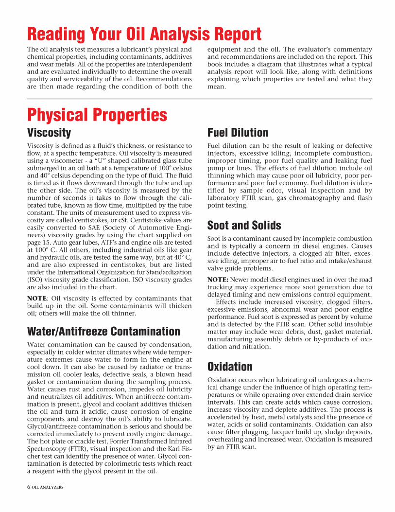
ViscosityViscosity is defined as a fluid’s thickness, or resistance toflow, at a specific temperature. Oil viscosity is measuredusing a viscometer - a “U” shaped calibrated glass tubesubmerged in an oil bath at a temperature of 100° celsiusand 40° celsius depending on the type of fluid. The fluidis timed as it flows downward through the tube and upthe other side. The oil’s viscosity is measured by thenumber of seconds it takes to flow through the cali-brated tube, known as flow time, multiplied by the tubeconstant. The units of measurement used to express vis-cosity are called centistokes, or cSt. Centistoke values areeasily converted to SAE (Society of Automotive Engi-neers) viscosity grades by using the chart supplied onpage 15. Auto gear lubes, ATF’s and engine oils are testedat 100° C. All others, including industrial oils like gearand hydraulic oils, are tested the same way, but at 40° C,and are also expressed in centistokes, but are listedunder the International Organization for Standardization(ISO) viscosity grade classification. ISO viscosity gradesare also included in the chart.
NOTE: Oil viscosity is effected by contaminants thatbuild up in the oil. Some contaminants will thickenoil; others will make the oil thinner.
Water/Antifreeze ContaminationWater contamination can be caused by condensation,especially in colder winter climates where wide temper-ature extremes cause water to form in the engine atcool down. It can also be caused by radiator or trans-mission oil cooler leaks, defective seals, a blown headgasket or contamination during the sampling process.Water causes rust and corrosion, impedes oil lubricityand neutralizes oil additives. When antifreeze contam-ination is present, glycol and coolant additives thickenthe oil and turn it acidic, cause corrosion of enginecomponents and destroy the oil’s ability to lubricate.Glycol/antifreeze contamination is serious and should becorrected immediately to prevent costly engine damage.The hot plate or crackle test, Forrier Transformed InfraredSpectroscopy (FTIR), visual inspection and the Karl Fis-cher test can identify the presence of water. Glycol con-tamination is detected by colorimetric tests which reacta reagent with the glycol present in the oil.
Fuel DilutionFuel dilution can be the result of leaking or defectiveinjectors, excessive idling, incomplete combustion,improper timing, poor fuel quality and leaking fuelpump or lines. The effects of fuel dilution include oilthinning which may cause poor oil lubricity, poor per-formance and poor fuel economy. Fuel dilution is iden-tified by sample odor, visual inspection and bylaboratory FTIR scan, gas chromatography and flashpoint testing.
Soot and SolidsSoot is a contaminant caused by incomplete combustionand is typically a concern in diesel engines. Causesinclude defective injectors, a clogged air filter, exces-sive idling, improper air to fuel ratio and intake/exhaustvalve guide problems.
NOTE: Newer model diesel engines used in over the roadtrucking may experience more soot generation due todelayed timing and new emissions control equipment.
Effects include increased viscosity, clogged filters,excessive emissions, abnormal wear and poor engineperformance. Fuel soot is expressed as percent by volumeand is detected by the FTIR scan. Other solid insolublematter may include wear debris, dust, gasket material,manufacturing assembly debris or by-products of oxi-dation and nitration.
OxidationOxidation occurs when lubricating oil undergoes a chem-ical change under the influence of high operating tem-peratures or while operating over extended drain serviceintervals. This can create acids which cause corrosion,increase viscosity and deplete additives. The process isaccelerated by heat, metal catalysts and the presence ofwater, acids or solid contaminants. Oxidation can alsocause filter plugging, lacquer build up, sludge deposits,overheating and increased wear. Oxidation is measuredby an FTIR scan.
Reading Your Oil Analysis ReportThe oil analysis test measures a lubricant’s physical andchemical properties, including contaminants, additivesand wear metals. All of the properties are interdependentand are evaluated individually to determine the overallquality and serviceability of the oil. Recommendationsare then made regarding the condition of both the
equipment and the oil. The evaluator’s commentaryand recommendations are included on the report. Thisbook includes a diagram that illustrates what a typicalanalysis report will look like, along with definitionsexplaining which properties are tested and what theymean.
Physical Properties
OIL ANALYZERS 7
NitrationNitration occurs during the fuel combustion processwhen combustion by-products mix with the engine oil.This occurs during normal engine operation but is alsoa result of abnormal blow-by. The products of nitrationare highly acidic. Their effects include accelerated oxi-dation, oil thickening, corrosion, increased wear andpoor engine performance. Nitration is measured byinfrared analysis or FTIR.
Other indicators that may suggest abnormal nitrationlevels are a rapid reduction in the oil’s reserve alkalinity(Total Base Number).
Total Base Number (TBN)Depending upon the application, different oils havedifferent blends of additives designed to maintain theoil’s lubricating properties and protect equipment. Base(alkaline) additives are present in automotive engine
oils to neutralize acidic by-products of combustion. Newoils start out with the strongest TBN they can possess,depending upon the base oil and the additive chemistryused to make them. Over its service life, a motor oilwill lose its ability to neutralize acids. Measuring the TBNstrength of the oil is very important when extending oildrain intervals, as the TBN value indicates the capabil-ity of the additives to protect the engine from acidic cor-rosion. The standard test for measuring an engine oil’sacid neutralizing strength, or Total Base Number, is theASTM-D 4739 Reserve Alkalinity Test. TBN is expressedusing a value number, which decreases as nitration andoxidation values rise over the service life of the oil.Because an oil’s characteristics are interdependent, TBNdepletion reflects other characteristics of the engine oilthat are out of acceptable range. This may indicate thatthe oil’s service life has ended and the oil should bechanged.
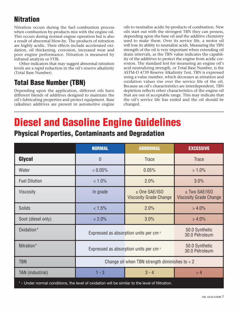
Diesel and Gasoline Engine GuidelinesPhysical Properties, Contaminants and Degradation
NORMAL ABNORMAL EXCESSIVE
Glycol 0 Trace Trace
Water < 0.05% 0.05% > 1.0%
Fuel Dilution < 1.0% 2.0% 3.0%
Viscosity In grade ± One SAE/ISO ± Two SAE/ISOViscosity Grade Change Viscosity Grade Change
Solids < 1.5% 2.0% > 4.0%
Soot (diesel only) < 2.0% 3.0% > 4.0%
Oxidation*Expressed as absorption units per cm-1
50.0 Synthetic30.0 Petroleum
Nitration*Expressed as absorption units per cm-1
50.0 Synthetic30.0 Petroleum
TBN Change oil when TBN strength diminishes to < 2
TAN (industrial) 1 - 3 3 - 4 > 4
* - Under normal conditions, the level of oxidation will be similar to the level of Nitration.

8 OIL ANALYZERS
2206 WINTER STREETSUPERIOR, WI 54880(715) 395-0222, FAX (715) 392-3097
CUSTOMER NO.: 3UNIT NO.: 9DESCRIPTION: SEND USER: S
END USER LOCATION: S
SAMPLE DATA
LAB# SAMPLE DATE TIME ON OIL RECEIPT DATE TIME ON UNIT IR
ON
CH
RO
MIU
M
LEA
D
CO
PP
ER
28995 11/14/2002 85 15 0 0 2NORMAL 02/03/2003 14227
LAB# ADDITIONAL TESTSTBN OXID NITR F-SOOT CHANGE
28995 10.74 9.0 7.0 0.42 NO
DAN HORNAMSOIL2206 WINTER STREETSUPERIOR, WI 54880
KeyA: Abnormal C: Critical
3
6
Customer Unit InformationThis section of the report lists theidentification of the unit sampled,equipment manufacturer, model andoil brand and type. This informationis supplied by the customer.
Spectrochemical AnalysisDetermines component wear, airbornedirt, cooling system contamination andoil additive concentrations. Informationis reported in parts per million (ppm).
Sample DataIndicates date sample was tested andthe hours/miles on the oil and unit. Thelaboratory sample number is used totrack the unit history.
Unit InformationMake, model, oil brand and type arereported here. This information issupplied by the customer.
Oil DegradationTotal Base Number (TBN) measures thealkaline reserve remaining in crankcaselubricants to neutralize acidic byproductsof combustion. For non-crankcaselubricants, the measurement of TotalAcid Number (TAN) provides a goodindication of a lubricant’s condition.
Physical PropertiesChanges in the physical qualities of thelubricant are determined and evaluated.These changes can have a dramaticeffect on the lubricant’s ability to pro-tect the component from wear or failure.
Recommendations andAdditional Test ResultsOur data provide specific informationabout the lubricant and your equipment.In case of imminent danger or pendingcatastrophic failure to a piece of equip-ment, the customer is alerted to theemergency by phone or fax whenavailable. Reporting of additional testresults may also be detailed in this area.
Graphical AnalysisCharts wear metals trends as thesample history develops.
1
2
3
4
5
6
8
7

OIL ANALYZERS 9
INC.30002980GSAMPLE ENGINESAMPLE CONTR.
SUPERIOR, WI 54880
MAKE: CATMODEL: 3406OIL BRAND: AMSOILOIL TYPE: AME 15W-40SERIAL NO.:FUEL TYPE: DIESEL
NO. COPIES: 1
SPECTROCHEMICAL ANALYSIS (ppm) PHYSICAL PROPERTIES
CO
PP
ER
TIN
ALU
MIN
UM
NIC
KE
L
SIL
VE
R
SIL
ICO
N
BO
RO
N
SO
DIU
M
MA
GN
ES
IUM
CA
LCIU
M
BA
RIU
M
PH
OS
PH
OR
US
ZIN
C
MO
LYB
DE
NU
M
TITA
NIU
M
VA
NA
DIU
M
PO
TAS
SIU
M
FUE
L(%
VO
L.)
VIS
@ 4
0 C
cSt
VIS
@ 1
00 C
cSt
WA
TER
(%)
SO
OT/
SO
LID
S(%
VO
L.)
GLY
CO
L
20 0 4 0 0 6 2 6 28 3854 0 1187 1306 0 0 0 0 < 1 N/A 16.26 0 0.4 NEG
GRAPHICAL ANALYSIS
LAB# ANALYSIS RECOMMENDATIONS
No History to Graph
28995 RESULTS OF TEST PERFORMED INDICATE NO CORRECTIVE ACTION REQUIRED.
1 2
4 5
8
7
EXAMPLE REPORT

10 OIL ANALYZERS
ELEMENTAL INTERPRETATION GUThis chart is to be used as a guide only. Levels will vary. Levels listed in partsper million. Levels are based on manufacturer recommended fluid drain interval.Shortened or extended intervals may present varied wear metal levels.
Element Diesel* Gasoline Transmission Final DriveN A E N A E N A E N A E
Iron 10/40 100 300 5/25 350 500 50/200 300 400 150/300 400 500
Chromium 1/8 12 15 5/20 25 40 10 20 30 10 20 30
Lead 15 30 75 30 70 150 20 50 150 20 50 150
Copper 3/15 50 150 5/30 100 300 5/250 325 400 50/150 250 300
Tin 15 20 30 20 30 40 10 20 30 10 20 30
Aluminum 10 15 25 5/20 30 40 10 30 50 - - -
Nickel 5 10 15 5 10 15 10 15 25 10 15 25
Silver 3 10 30 3 10 30 - - - - - -
Silicon† 15 25 30 20 30 40 30 40 50 30 40 50
Sodium 25 100 150 20 100 150 30 40 50 50 150 200
N = Normal A = Abnormal E = Excessive
Manganese, Boron, Magnesium, Calcium, Barium, Phosphorus, Zinc and Molybdenum - Fluid additive syscases contaminate. No standard levels.† = Over oil baselineTitanium, Vanadium and Cadmium wear elements - no standard levels established.* = Automotive DieselNormal levels will vary due to operating conditions, component age and manufacturing differences.
Spectrochemical
Wear metals identified by spectrochemical analysis areexpressed in parts per million (PPM) of the environ-ment they inhabit. The sizes of wear metal particlesthat can be identified by spectrochemical analysis arebetween 3 and 10 microns. To put the linear measure-ment of a one micron particle into perspective, 1 micron= 0.000039/inch. When equipment is in operation, itgenerates wear metal particles which are carried by thelubricant as it flows through the components of themachine. Under normal conditions, the generation of
Wear Metals Analysis(Spectrochemical)
wear metals is very gradual and increases slowly as theequipment is used. It is important to remember thesepoints concerning wear metals:
• No two pieces of equipment wear at the same rate.
• Even identical pieces of equipment will exhibit varia-tion in their rate of internal wear.
• How equipment is used will affect wear rates. Vehicles,for example, which are subjected to continuous stop

OIL ANALYZERS 11
UIDE
AutomaticTransmissionN A E
0 50 100 250
0 5 10 20
0 30 70 150
0 50 100 250
0 5 20 50
10 30 50
5 10 15 25
- - -
0 30 40 50
0 30 100 150
stem and/or in certain
and go driving or heavy towing will experience a greater rate of internal wearthan those operated continually at highway speeds with no tow load.
• When equipment is new, initial break in wear rates will be higher. Whenequipment is reaching the end of its service life internal rates of wear willalso increase.
• The amount of time or miles on the oil reflects the level of wear metals pre-sent in the sample. For example, when using extended drain capablemotor oils and extending oil drains beyond conventional recommendedintervals, wear metals will exhibit an accumulative effect which indicateshigher PPM levels.
• Repairs made to the equipment can affect the wear metal rate by skewingthe PPM of metals present in the fluid. Opening an engine or replacing acomponent can expose the engine’s lubricating oil to outside contaminants,manufacturing residual particulate and seal material residue.
• Chips or metal particles visible to the eye are not detected by spectromet-ric analysis. Equipment failure can sometimes occur without significant pro-duction of detectable wear metals, as in cases where rapid failure or fatiguefailure takes place.
An elemental interpretation guide has been provided in this book. Pleaseremember that these range limits are to be used as a GUIDELINE only. Manyfactors will influence the wear metals results your sample receives based uponyour particular application. The range limits stated in the interpretation guideare based upon recommended petroleum oil drain intervals. Wear metalsource charts, which are also included in this book, can help identify thesource of wear metals that may have been tested as abnormal.
PHYSICAL PROPERTIES
IRO
N
CH
RO
MIU
M
LEA
D
CO
PP
ER
TIN
ALU
MIN
UM
NIC
KE
L
SIL
VE
R
SIL
ICO
N
BO
RO
N
SO
DIU
M
MA
GN
ES
IUM
CA
LCIU
M
BA
RIU
M
PH
OS
PH
OR
US
ZIN
C
MO
LYB
DE
NU
M
TITA
NIU
M
VA
NA
DIU
M
PO
TAS
SIU
M
FUE
L(%
VO
L.)
VIS
@ 4
0 C
cSt
VIS
@ 1
00 C
cSt
WA
TER
(%)
SO
OT/
SO
LID
S(%
VO
L.)
GLY
CO
L
Gasoline and DieselEngine Wear Metals
Oil Additives
15 0 0 20 0 4 0 0 6 2 6 28 3854 0 1187 1306 0 0 0 0 < 1 N/A 16.26 0 0.4 NEG
As is illustrated above, iron, chromium, lead, copper, tin and aluminum are wear metals specific to gasoline and dieselengines. These are listed to the left on the spectrochemical analysis report. Nickel and silver are rarely seen in an analysis report.
Oil additives and some contaminants are listed to the right on the spectrochemcial analysis. These cover a rangeof items from silicon to potassium.
SPECTROCHEMICAL ANALYSIS (ppm)

Journal Bearings X X X XBushings X X X XCam Shaft XCoolant Additives X X X XCrankshaft XCylinder Walls X XExhaust Valve X XAnti-Friction Bearing XGasket Materials X XGasoline Additive X XHousing/Castings X X XIngested Dirt X XOil Additive X X XOil Cooler XOil Pump Bushing X X X XOil Pumps X XPistons X X XRings X XThrust Washers X X X XTiming Gears XTurbo-Charger/Super-Charger X XValve Guides X XValve Train XWrist Pin-Bushings X X X XWrist Pins X
When trace metals are detected, the Iron Copper Lead Aluminum Silicon Chromium Tin Sodium Potassiumfollowing components could be the source: Fe Cu Pb Al Si Cr Sn Na K
WEAR METAL REFERENCE GUIDE - Engine
Bushings X X X XClutch Faces X XCoolant Additives X X X XAnti-Friction Bearings XGears XIngested Dirt XOil Additives XOil Cooler X XPumps X XThrust Washers X X XGasket Materials or Silicon Sealant X XHousing/ Castings X X X
When trace metals are detected, the Iron Copper Lead Aluminum Silicon Chromium Tin Sodium Potassiumfollowing components could be the source: Fe Cu Pb Al Si Cr Sn Na K
WEAR METAL REFERENCE GUIDE - Manual Transmission
12 OIL ANALYZERS

Journal Bearings X X X X XBushings X X XCoolant Additives X X XAnti-Friction Bearings XGasket Materials and Silicone Sealant X XGears X XIngested Dirt XShafts XThrust Washers X X XValves XHousing/Castings X X X
When trace metals are detected, the Iron Copper Lead Aluminum Silicon Chromium Tin Sodium Potassiumfollowing components could be the source: Fe Cu Pb Al Si Cr Sn Na K
WEAR METAL REFERENCE GUIDE - Automatic Transmission
Journal Bearings X X X XBushings X X XAnti-Friction Bearings XGears XIngested Dirt XOil Additives XOil Pump X XRoad Salt XShafts XThrust Washers X X XGasket Materials and Silicon Sealant X XHousing/Castings X X X
When trace metals are detected, the Iron Copper Lead Aluminum Silicon Chromium Tin Sodium Potassiumfollowing components could be the source: Fe Cu Pb Al Si Cr Sn Na K
WEAR METAL REFERENCE GUIDE - Differential Drive
Journal Bearings X X XBushings X X XAnti-Friction Bearings XGasket Materials or Silicone Sealants X XGears X XIngested Dirt XOil Additives XPumps X X XShafts XThrust Washers X XHousing/Castings X X X
When trace metals are detected, the Iron Copper Lead Aluminum Silicon Chromium Tin Sodium Potassiumfollowing components could be source: Fe Cu Pb Al Si Cr Sn Na K
WEAR METAL REFERENCE GUIDE - Industrial Gears
OIL ANALYZERS 13
14 OIL ANALYZERS
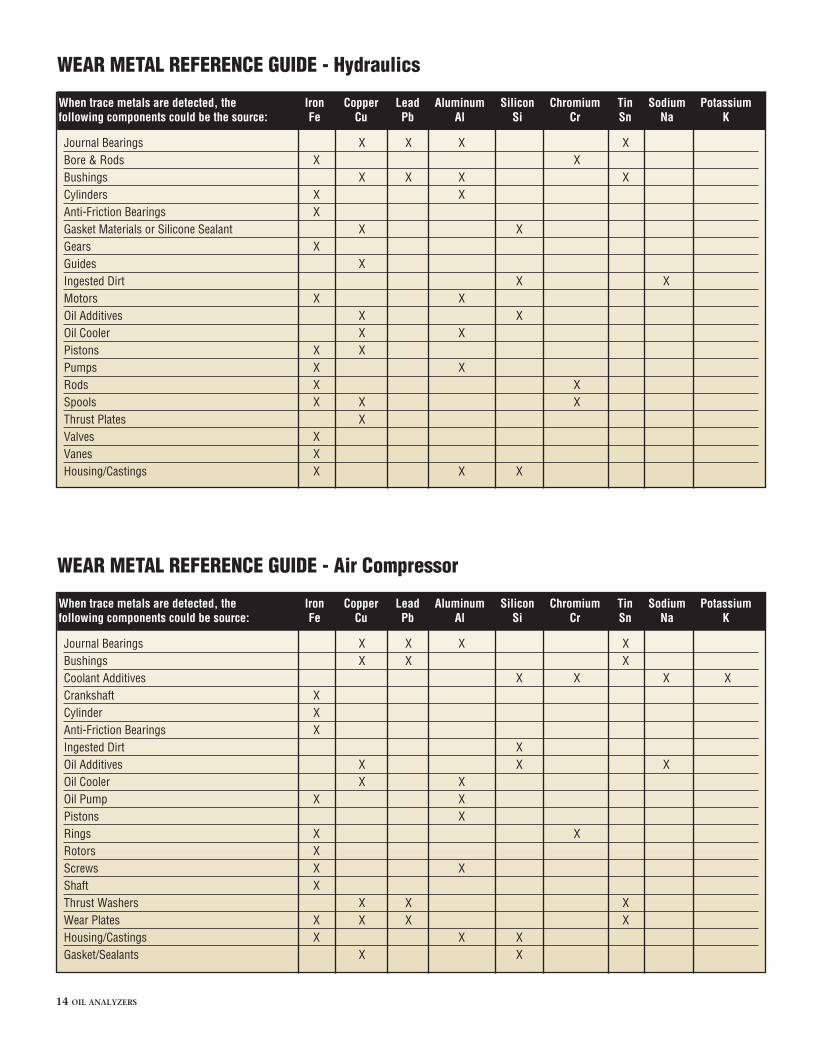
Journal Bearings X X X XBore & Rods X XBushings X X X XCylinders X XAnti-Friction Bearings XGasket Materials or Silicone Sealant X XGears XGuides XIngested Dirt X XMotors X XOil Additives X XOil Cooler X XPistons X XPumps X XRods X XSpools X X XThrust Plates XValves XVanes XHousing/Castings X X X
When trace metals are detected, the Iron Copper Lead Aluminum Silicon Chromium Tin Sodium Potassiumfollowing components could be the source: Fe Cu Pb Al Si Cr Sn Na K
WEAR METAL REFERENCE GUIDE - Hydraulics
Journal Bearings X X X XBushings X X XCoolant Additives X X X XCrankshaft XCylinder XAnti-Friction Bearings XIngested Dirt XOil Additives X X XOil Cooler X XOil Pump X XPistons XRings X XRotors XScrews X XShaft XThrust Washers X X XWear Plates X X X XHousing/Castings X X XGasket/Sealants X X
When trace metals are detected, the Iron Copper Lead Aluminum Silicon Chromium Tin Sodium Potassiumfollowing components could be source: Fe Cu Pb Al Si Cr Sn Na K
WEAR METAL REFERENCE GUIDE - Air Compressor

OIL ANALYZERS 15
INC.
2 1.98 2.423 2.88 3.525 4.14 5.067 6.12 7.4810 9.00 11.015 13.5 16.522 19.8 24.232 28.8 35.2
46 (AGMA 1)* 41.4 50.668 (AGMA 2) 61.2 74.8100 (AGMA 3) 90.0 110150 (AGMA 4) 135 165220 (AGMA 5) 198 242320 (AGMA 6) 288 352460 (AGMA 7) 414 506680 (AGMA 8) 612 748
1000 (AGMA 8A) 900 11001500 1350 1650
ISO Viscosity Min MaxGrade @ 40° C cSt. cSt.
ISO VISCOSITY GRADE @ 40° C (INDUSTRIAL FLUIDS)
20 5.6 >9.330 9.3 >12.540 12.5 >16.350 16.3 >21.960 21.9 >26.0
90 13.5 >24.0140 24.0 >41.0250 41.0 No Req.
SAE ENGINE OIL Min MaxGRADE @ 100° C cSt. cSt.
SAE Gear Oil Min MaxGrade @ 100° C cSt. cSt.
SAE ENGINE AND GEAR OIL VISCOSITY GRADE @ 100° C (AUTOMOTIVE FLUIDS)
*AGMA (American Gear Manufacturers Association) viscosity specification
Phone: 1-715-395-0222 • Fax: 1-715-392-3097Email: [email protected] • Website: oaitesting.com

INC.
Oil Analyzers Inc., 2206 Winter St., Superior, WI 54880 (715) 395-0222Printed in U.S.A. © Copyright 2004 G-2047 7/04
Tips for Completing OAIInformation FormsThe sample information sheet is a very important part of theoil analysis test kit. The amount of information a user providesabout the unit being tested and the oil being used is directlyrelated to the accuracy of OAI test results.
The following information is very important in expediting theprocessing of a test sample and getting the most accurate results:
1. Your name (An account number will be assigned toyou from the lab.)
2. Your complete address
3. Telephone number
4. Fax number (If you have one.)
5. The make, model and year of your equipment
6. The unit number (A number designation or name ofthe component which identifies it - i.e. “vehicle #12.”You may choose one for yourself if you do not alreadyhave a set number. Just be sure to identify the equip-ment with the same number each time it is tested.)
7. The component type (Gasoline engine, diesel engine,etc.)
8. The oil brand and viscosity (For gasoline and dieselengines, use the SAE grade - i.e. 5W-30 or 10W-40.)
9. How much oil has been added since the last oilchange
10. Filter change date and type of filters used
• Full Flow - This is the type of filter that a vehicle hasmounted on its engine block.
• By Pass - A by-pass filter is a type of add-on filtrationthat did not come with your vehicle.
11. The date the current oil was installed
12. The date the current oil was sampled
13. The miles/hours on the vehicle or equipment
14. The miles/hours on the oil
Add any notes you feel would be important or helpful inprocessing your sample to the bottom section of the formunder the COMMENTS/INSTRUCTIONS heading.
NOTE: The numbered sticker on the bottom of the sampleinformation form identifies the form with yoursample. It is not an account number.
INC.
INC.
IMPORTANT – PLACE ON BOTTLE
2206 WINTER STREET • SUPERIOR, WISCONSIN 54880TEL: 715-395-0222 • FAX: 715-395-0222
CUSTOMER INFORMATION
ACCOUNT NUMBER:
ACCOUNT NAME:
ADDRESS:
CITY:
STATE/PROV.: ZIP/POST:
CONTACT:
PHONE: FAX:
E-MAIL:
ADDRESS CHANGE: YES � NO �
EQUIPMENT INFORMATION
UNIT / CODE NO:
TESTED BEFORE? YES � NO �
MAKE: YEAR:
MODEL: ENG. SIZE:
SERIAL/NO.:
COMPONENT: (CHECK)
� Gasoline Engine � Hydraulic System
� Diesel Engine � Compressor
� Natural Gas Engine � Industrial-Gear
� Manual Transmission � Industrial-Bearing
� Automatic Transmission � Gas Turbine
� Differential � Steam Turbine
� Hydrostatic Drive � Circulating Oil
� Other (please specify below)
SAMPLE INFORMATION
OIL BRAND:
VISCOSITY: SAE: ISO:
SUMP CAPACITY: OIL ADDED:
FILTER: FULL FLOW: BY-PASS:
FILTER CHANGE DATE: FULL FLOW BY-PASS
OIL CHANGED NOW? YES � NO �
DATE INSTALLED: Mi/Km/Hr:
DATE SAMPLED: Mi/Km/Hr:
TOTAL Mi/Km/Hr ON SAMPLE:
TOTAL Mi/Km/Hr ON UNIT:
COMMENTS/INSTRUCTIONS
ADDITIONAL COPY TO: