Embed Size (px)
Citation preview
www.worldpumps.com
WORLD PUMPS May 2012Applications26
Oil & gas
Oil pipeline from Siberia to the seaThe idea of transporting oil in pipelines from inland wells to sea ports, was suggested by Russian
scientist Dmitri Mendeleev in 1863, and in 1878 the American Nobel brothers built a pipeline
in the US. Tested and tried as the concept is, the transportation of oil across 4857 km is still no
mean engineering feat.
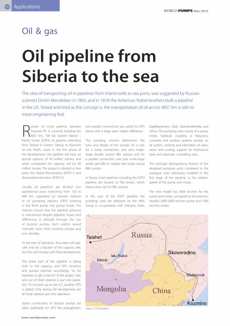
Russian oil trunk pipeline operator Transnet Plc is currently building the 4857 km, 100 bar Eastern Siberia –
Pacific Ocean (ESPO) oil pipeline extending from Taishet in Eastern Siberia to Kozmino on the Pacific coast. In the first phase of the development, the pipeline will have an annual capacity of 30 million tonnes, and when completed the capacity will be 80 million tonnes. The project is divided in two parts, the Taishet-Skovorodino (ESPO-1) and Skovorodino-Kozmino (ESPO-2).
Usually oil pipelines are divided into operational areas stretching from 150 to 600 km, separated by booster stations or oil pumping stations (OPS) working in the ‘from pump into pump’ mode. The stations ensure that the pipeline pressure is maintained despite pipeline losses and differences in altitude through the use of booster pumps. Each station would normally have three working pumps and one standby.
At the start of operation, flow-rates will typi-cally only be a fraction of the capacity rate, but this will increase with field development.
The linear part of the pipeline is being built to full capacity, and OPS locations and pumps selected accordingly. So, for example, to get a rate 0.5 of the project rate, one out of three stations is put into opera-tion. To increase up to rate 0.7, another OPS is added. Only during full development are all three stations put into operation.
Series connections of booster pumps are often preferable for OPS flat arrangement;
and parallel connections are suited for OPS plants with a large static height difference.
The pumping scheme determines the type and design of the pumps. As a rule, for a series connection, one uses single-stage double suction BB1 pumps, and for a parallel connection, one uses multi-stage axially split BB3 or radially split single casing BB4 pumps.
In Russia, most pipelines including the ESPO pipeline, are located on flat terrain, which means they opt for BB1 pumps.
In the case of the ESPO pipeline, the pumping units are delivered by the HMS Group in co-operation with Siemens, Voith,
EagleBurgmann, Elsib, Gasholodtehnika and others. The pumping units consist of a pump, motor, hydraulic coupling or frequency converter and auxiliary systems namely: an oil system, working and lubrication oil sepa-ration and cooling, support for mechanical seals and automatic controlling units.
The principal distinguishing feature of the designed pumping units, compared to the analogue ones previously installed in the first stage of the pipeline, is the rotation speed of the pump and motor.
The new model has 3000 rev/min for the pump and motor, compared to the previous model’s 2400-2800 rev/min pump and 1500 rev/min motor.
Figure 1. ESPO pipeline
www.worldpumps.com
WORLD PUMPS May 2012Applications 27
The upgrade means that the main dimen-sions of the pumping units and pumping stations have increased, which has led to higher capital expenditures. It also means a decrease in the unit efficiency of 1-2% and the need to increase the oil-system capacity with a complex cooling system.
The main task was to provide energy-effi-cient and reliable operation of the pumping units, which was achieved with a double suction pump with optimized flow parts.
The result is pump efficiency of 90% at full operation.
It is important, however, that efficiency is maintained not only when the pipeline operates at full capacity, but also when operating at lower rates. Replaceable impel-lers are traditionally used for this purpose, as they can improve pump efficiency and reduce vibrations. This was combined with additional diffusers to solve the problem of operational fluctuations. As a result, pump efficiency in modes 0.5 Q nom, 0.7 Q and 1.0 Q are practically the same.
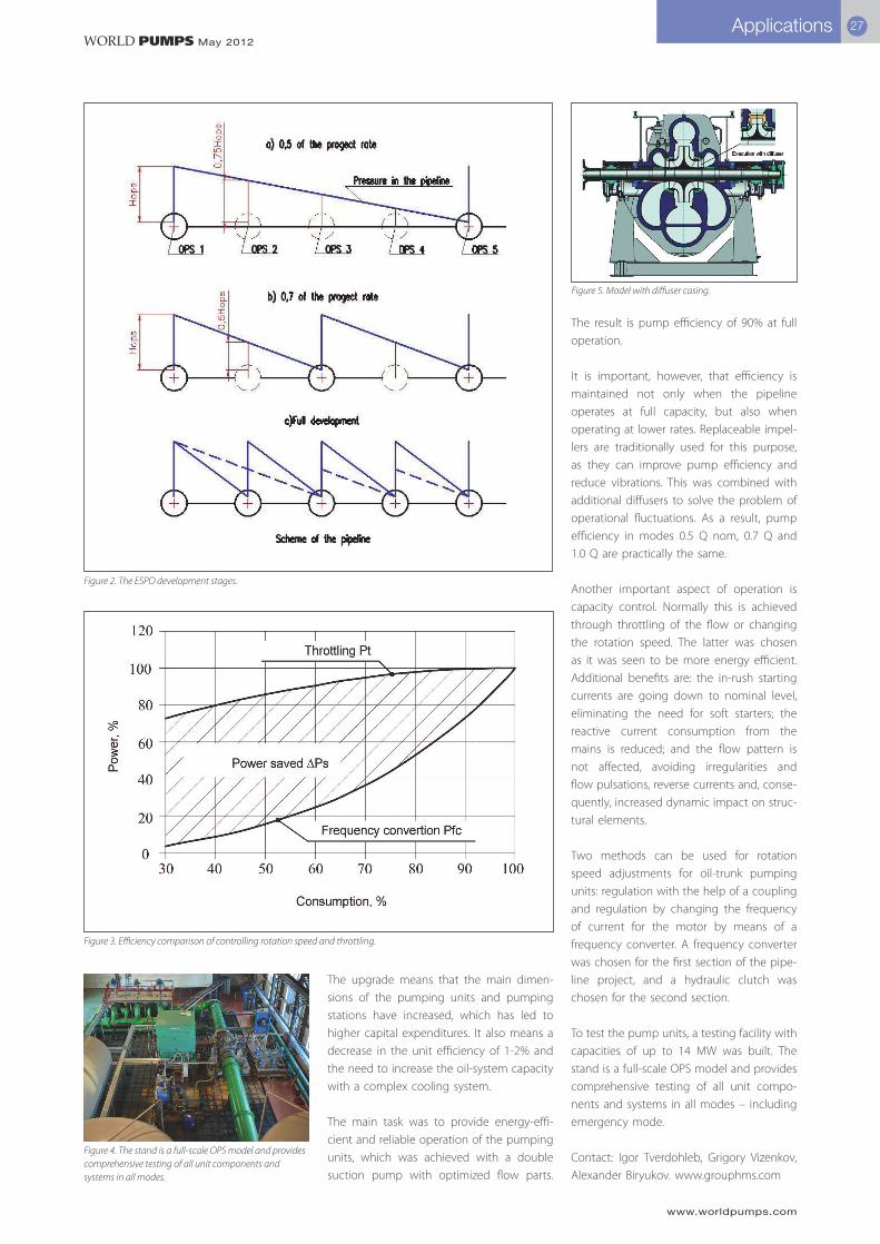
Another important aspect of operation is capacity control. Normally this is achieved through throttling of the flow or changing the rotation speed. The latter was chosen as it was seen to be more energy efficient. Additional benefits are: the in-rush starting currents are going down to nominal level, eliminating the need for soft starters; the reactive current consumption from the mains is reduced; and the flow pattern is not affected, avoiding irregularities and flow pulsations, reverse currents and, conse-quently, increased dynamic impact on struc-tural elements.
Two methods can be used for rotation speed adjustments for oil-trunk pumping units: regulation with the help of a coupling and regulation by changing the frequency of current for the motor by means of a frequency converter. A frequency converter was chosen for the first section of the pipe-line project, and a hydraulic clutch was chosen for the second section.
To test the pump units, a testing facility with capacities of up to 14 MW was built. The stand is a full-scale OPS model and provides comprehensive testing of all unit compo-nents and systems in all modes – including emergency mode.
Contact: Igor Tverdohleb, Grigory Vizenkov, Alexander Biryukov. www.grouphms.com
Figure 2. The ESPO development stages.
Figure 5. Model with diffuser casing.
Figure 3. Efficiency comparison of controlling rotation speed and throttling.
Figure 4. The stand is a full-scale OPS model and provides comprehensive testing of all unit components and systems in all modes.