Embed Size (px)
Citation preview
RD-ft79 799 SITING CRITERIA FOR MICROURVE LANING SYSTTNS (NLS)(U) vi1
OHIO UNIV ATHENS AVIONICS ENGINEERING CENTERRDCL 1FF ET AL. JUN 96 OU-AEC-6±-1 DOT/FAAR/PN-SS/1S
UNCLSSIFIED DTRS57-63-C-66697 F/G 1717 M

%- %'%
%%
%~ %
1~ ~~~ -# L q
AW~~ AI,,A
Ar* 41 1.1r.
% *I % % % 4 %
J, 5,6
o * -. 'r f
45 k5,1
Al-0-
DOT/FAA/PM-86/18 Siting Criteria for MicrowaveProgram Engineering Landing Systems (MLS)and Maintenance ServiceWashington, D.C. 20591
¢, . ;
Roger RadcliffMichael F. DiBenedetto
Avionics Engineering Center
Department of Electrical andComputer Engineering
Ohio UniversityAthens, Ohio 45701 .-
June 1986
I"Final Repor
This document is available to the publicthrough the National Technical InformationService, Springfield, Virginia 22161
oDTICELECTE
.... ~AUG 111986SUS Deportment of Transportation
cmFederal Aviation Administration B
86 800 8
TIC,74 7 7 7 FT
NOT icEF
This document is disseminated under the sponsorship of
the Department of Transportation in the interest of
information exchange. The United States Government
assumes no liability for the contents or use thereof.
'36 1 19 Ak
Te-+nical R~eport Oocumrntittion Pogo1. Report Me.. Govemment Access.on N^. 3.~ Recip..ri's Coogioq ..
DOT/FAAIPM-86/18 I.I
Siting Criteria for Microwave Landing Systems (MLS) Vh
3. Pri.f0n..,,g O.9an.itat.e. Report N.7.A. Ih..' *
RgrRadcliff and Michael F. DiBenedetto Oil -AEC -81 I
Avonics Engineeringent
Ohi UnverityDTRS57 81( UC()())/Athens, Ohio 4570113TyeoReotndPrdCvrd
1 2. Spaagar~ng Agency Nome end AddressU..Department of Transportation
Federal Aviation Administration FINAL REPORT
Program Engineering and Maintenance Service 14. Sow,soving Agency Cad.IWashington, D. C. 205911 ______________
U.S. Department of TransportationITransportation -System CenterKendall Square, Cambridge, Massachusetts 02142
;6. Abtrc
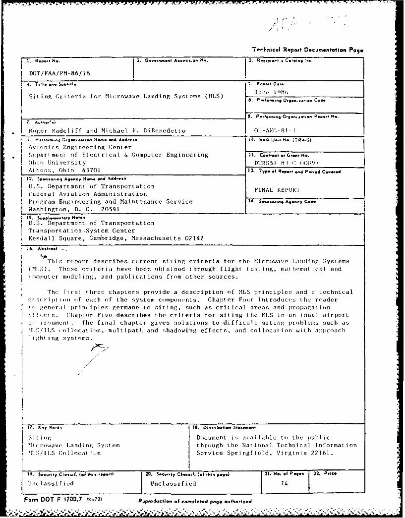
This report describes current siting criteria for the Microwave Landing Systems(ML;) . These cr itecria have been obt ained through f light test i ng, mnat hemat ical and(.omputer modeling, and publications from other sources.
The first three chapters provide a description of MLS p~rinciples and a technicaldcscri pt ion of each of the system components. Chapter Four introduces the readerto general principles germane to siting, such as critical areas and propag~ationf f .(-t s. Cha pter Fi ve descr ibes t he cr iter ia for si ting t he MLS i n an i deal ai rport
er:,:irrnment . The final chapter gives solutions to difficult siting problems such ascT/ISollocation, multipath and shadowing effects, and collocation with approach
lighting systems.
1.Key Words 1s. Distribution Statement
Si ti ng Document i s ava i Ilable to thte publ icMicrowave Landing System through the National Technical Information
MSISCollocat .,n Service Springfield, Virginia 22161.
19. Security CI.,s.I. (ofthis. rsoavt, 20. Security cinssil. %,aI ti% pug.) 21. No. of Palo$ 22 Price
Ucasified Unclassified 1 74
Form DOT F i700.7 (8-72) Riaproducteuv of completed page oathezerd
V. . .
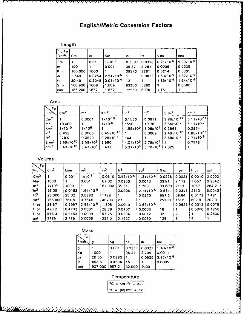
English/Metric Conversion Factors
Length
Fro Cm m Km in ft s mI nmi
Cm 1 0.01 lx1o 5 03937 0.0328 6 21x10 6 5.39x10⁻⁶
m 100 1 0.001 39.37 3.281 0.0006 00005
Km 100.000 1000 1 39370 3281 0.6214 0.5395
in 2.540 0.0254 2.54x 10⁻⁵ 1 00833 1.58x10 5 1.37x10 5
ft 30-48 0.3048 3.05x10⁻⁴ 12 1 1.89x10
4 1.64x10⁴
S ma 160.900 1609 1.609 63360 5280 1 08688nrn 1 185,200 1852 1.852 72930 6076 1.151 1
Area
Cm 2 m 2 Km 2 in 2 ft 2 S mi2 nm 2
Cm 2 1 0.0001 1x10 1 0 0.1550 0.0011 3.86x10⁻¹ 1 5.11x10 1 1
r, 2 10.000 1 lxlO 6 1550 10.76 3.86x10 7 5.11x10⁻⁷
Km 2 1x10 10 1x10 6 1 1.55x10 9 1.08x10 7 0.3861 0.2914
an2 6.452 0.0006 6.45x 10⁻¹⁰ 1 0.0069 2.49x10 1 0 1.88x10 0
ft 2 929.0 00929 9.29x10⁻⁸ 144 1 3.59x10⁻⁸ 2.71 x 10'8S m12 2.59x10 10 2.59x10⁶ 2.590 4.01x10 9 2.79x10 7 1 0.7548 %
nmi2 3.43x10¹⁰ 3 43x106 3.432 5.31x10 9 3.70x10 7 1.325 1
Volume
Cm 3 Liter m3 In3 ft 3 yd 3 fi oz fl pt fi qt gal
Cm 3 1 0.001 lx106 0.0610 3.53x10 5 1.31x10⁻⁶ 0.0338 0.0021 0.0010 0.0002liter 1000 1 0.001 61.02 0.0353 0.0013 33.81 2.113 1.057 0.2642m 2 Ix10 6 1000 1 61,000 35.31 1.308 33.800 2113 1057 264.2
in3 16.39 0.0163 1.64x10⁻⁵ 1 0.0006 2.14x10⁵ 0.5541 0.0346 2113 0.0043ft 3 28.300 28.32 0.0283 1728 1 00370 957.5 59.84 0.0173 7.481yd3 765,000 764 5 0.7646 46700 27 1 25900 1616 807.9 202.0fIoz 29,57 0.2957 2 96x10 5 1 805 0.0010 3 87x10 5 1 0.0625 0.0312 0.0078fl pt 473.2 04732 0.0005 28 88 0.0167 0.0006 16 1 0.5000 0.1250fl qt 9463 09463 00009 57.75 00334 00012 32 2 1 0.2500gal 3785 3 785 00038 231 0 01337 00050 128 8 4 1
Mass
Fro g Kg oz lb ton
g 1 0.001 0.0353 0.0022 1.1OxlO 6
Kg 1000 1 35.27 2.205 0.0011oz 28.35 0.0283 1 00625 3.12x10 5
lb 453.6 0.4536 16 1 0.0005
ton 907,000 907.2 32,000 2000 1
Temperature
°C 5/9 (OF - 32)
OF= 915(°C) + 32
'- - -- • "'-
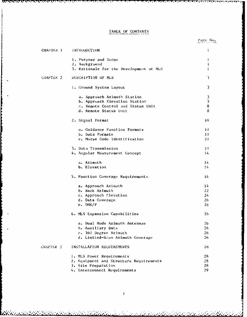
TABLE OF CONTENTS
Page No.
CHAD' FER I INTRODUCTION I
1. Purpose and Scope I2. Background 13. Rationale for the Development ot MLS I
CDAPTER 2 IOESCR[PTION OF MLS 3
1. Ground System Layout 3
a. Approach Azimuth Station 3b. Approach Elevation Station 3c. Remote Control and Status Unit 8d. Remote Status Unit 8
2. Signal Format 10
a. Guidance Function Formats I1)b. Data Formats 10c. Morse Code Identification 10
3. Data Transmission IC)4. Angular Measurement Concept 14
a. Azimuth 14
b. Elevation 14
5. Function Coverage Requirements 14
a. Approach Azimuth 14b. back Azimuth 22c. Approach Elevation 24d. Data Coverage 26e. DME/P 26
6. MLS Expansion Capabilities 26
a. Dual Mode Azimuth Antennas 26b. Auxiliary Data 26
c. 360 Degree Azimuth 26d. Limited-Scan Azimuth Coverage 26
CGAPTR 3 INSTALLATION REQUIREMENTS 28
1. MLS Power Requirements 28
2. Equipment and Structure Requirements 283. Site Preparation 284. Interconnect Requirements 29
• --. l . -.- % ..-. .- ..... ..... ......-*p. ~ j L . f 2 - ,22 ... . . .. , ... . . 2. .. .
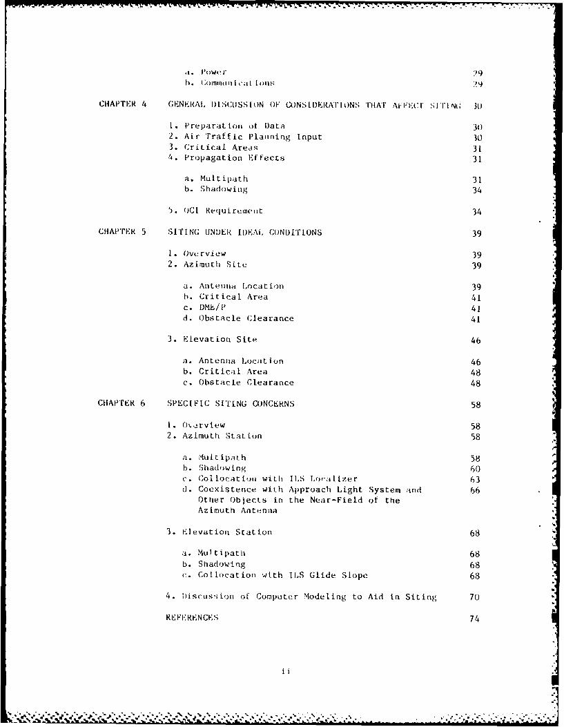
.I. Powe1). (C(mnili I i (a[ |()u11 ,9;
CHAPTER 4 GENERAL I)ISCJSSION OF CONS L I)ERAI' ONS THAT AI.'I'Cr Si'r I N(; JO
1. Preparation ot Data 302. Air Traffic Planning Input 303. Critical Areas 314. Propagation Effects 31
a. MuLtipath 31b. Shadowing 34
5. ()CI Requirumet 34
CHAPTER 5 SITING UNDER II)EAIL CONDIT[ONS 39
1. Overview 392. Azimuth Site 39
a. Antenna Location 39b. Critical Area 41c. DME/P 41d. Obstacle Clearance 41
3. Elevation Site 46
a. Antenna Location 46b. Critical Area 48c. Obstacle Clearance 48
CHAPTER 6 SPECIFIC SiT[NG CONCERNS 58
1. O.rview 582. Azimuth Stat ion 58
a. Mult ipath 58b. Shadowing 60c. Collocation with ILS Localizer 63d. Coexistence with Approach Light System and 66
Other Objects in the Near-Field of theAzimuth Antenna
3. Klevation Station 68
a. Multipath 68b. Shadowing 68c. Collocation with ILS Glide Slope 68
4. Discussion of Computer Modeling to Aid in Siting 70
REFERENCES 74
ii
t q -J -' % l" '-'"n%
- , *" . .- " m . J -. ' ". " . -,--"%"• % . • .- . . . - . " "-"- -",
..... *-, ....1 ...- . .. ! I . . . . -I t
LIST OF FIGURES AND TABLES
Figure I'zi,,-_N .
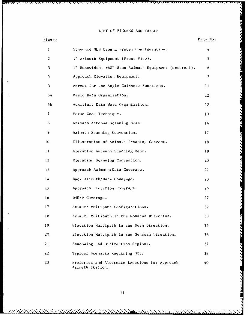
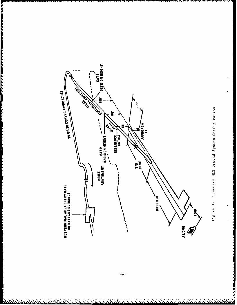
1 Standard MLS Ground System Cont igurat ion. 4
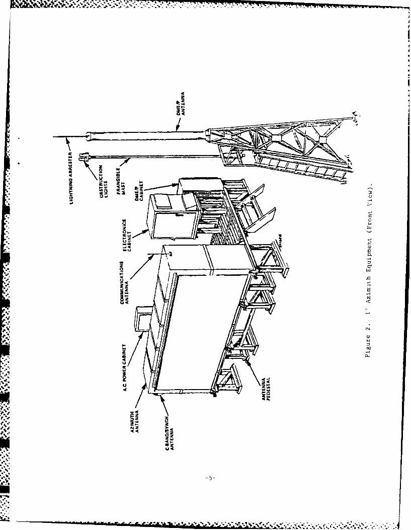
2 10 Azimuth Equipment (Front View). 5
3 1* Beamwidth, ±400 Scan Azimuth Equipment (external). 6
4 Approach Elevation Equipment. 7
5 Format for the Angle Guidance Functions. 11
6a Basic Data Organization. 12
6b Auxiliary Data Word Organization. 12
7 Morse Code Technique. 13
8 Azimuth Antenna Scanning Beam. 16
9 Azimuth Scanning Convention. 17
10 Illustration of Azimuth Scanning Concept. 18
11 Elevation Antenna Scanning Beam. 19
12 Elevation Scanning Convention. 20
13 Approach Azimuth/Data Coverage. 21
14 Back Azimuth/Data Coverage. 23
15 Approach Elevation Coverage. 25
16 DME/P Coverage. 27
17 Azimuth Multipath Configurations. 32
18 Azimuth Multipath in the Nonscan Direction. 33
19 Elevation Multipath in the Scan Direction. 35
20 Elevation Multipath in the Nonscan Direction. 36
21 Shadowing and Diffraction Regions. 37
22 Typical Scenario Requiring OCI. 38
23 Preferred and Alternate Locations for Approach 40Azimuth Station.
iii
- j.:I - *- . .~-.*.- ~.-..>***-.*-*. ... ~ ..
IIS[' OF FIGURES AND 'rABLES (c'ont illd I
Figure Page No.
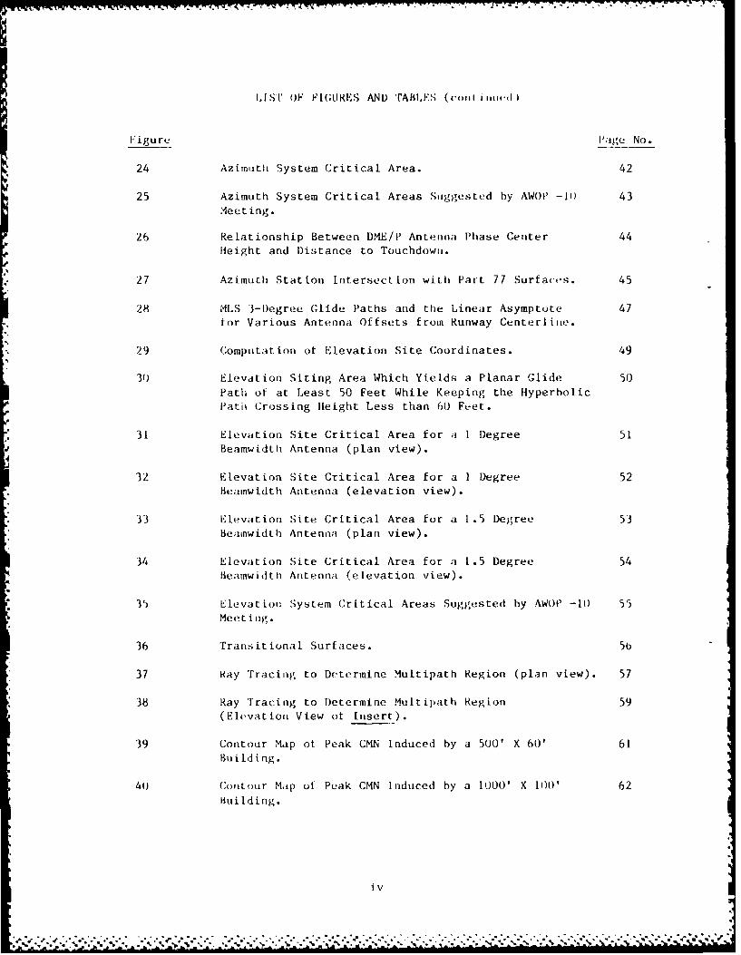
24 Azimuth System Critical Area. 42
25 Azimuth System Critical Areas Suggested by AWOP' -I) 43Meet ing.
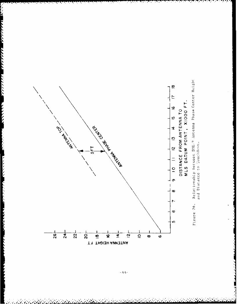
26 Relationship Between DME/P Antenna Phase Center 44Height and Distance to Touchdown.
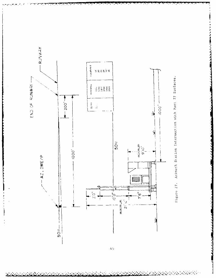
27 Azimuth Station Intersection with Part 77 Surfaces. 45
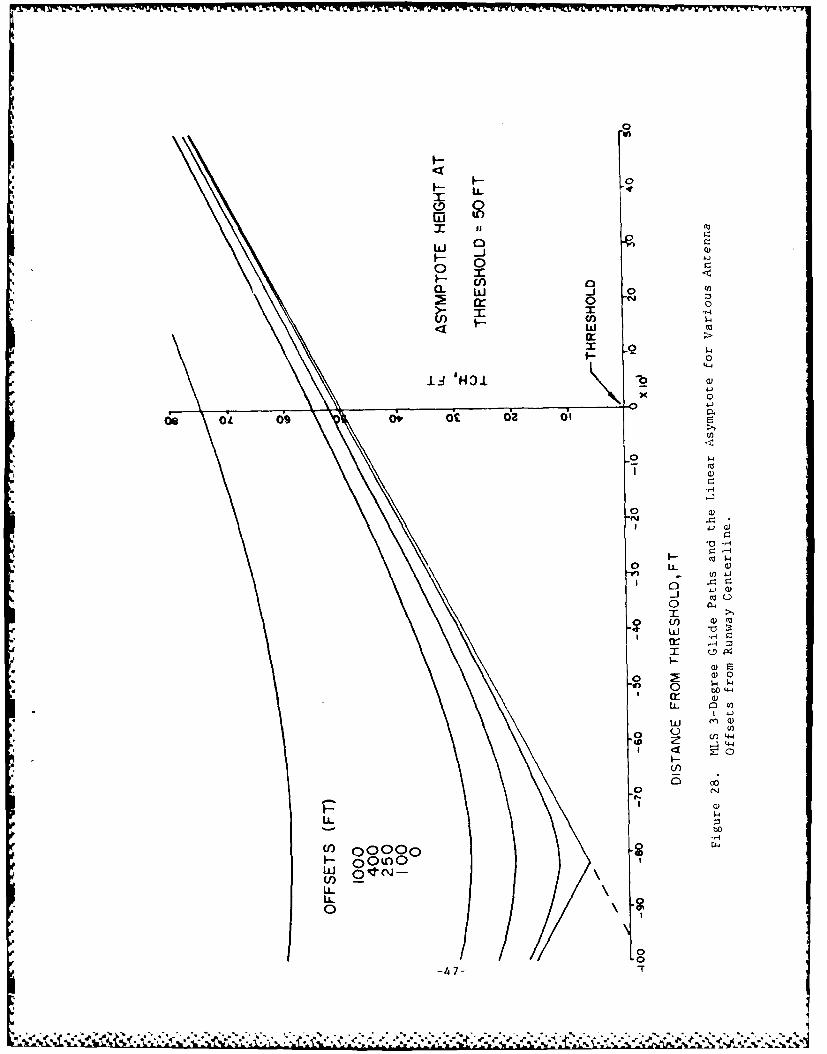
28 MLS 3-Degree Glide Paths and the Linear Asymptote 47for Various Antenna Offsets from Runway Centerline.
29 Computation of Elevation Site Coordinates. 49
30 Elevation Siting Area Which Yields a Planar Glide 50Path of at Least 50 Feet While Keeping the HyperbolicPath Crossing Height Less than 60 Fi-et.
31 Elevation Site Critical Area for a I Degree 51Beamwidth Antenna (plan view).
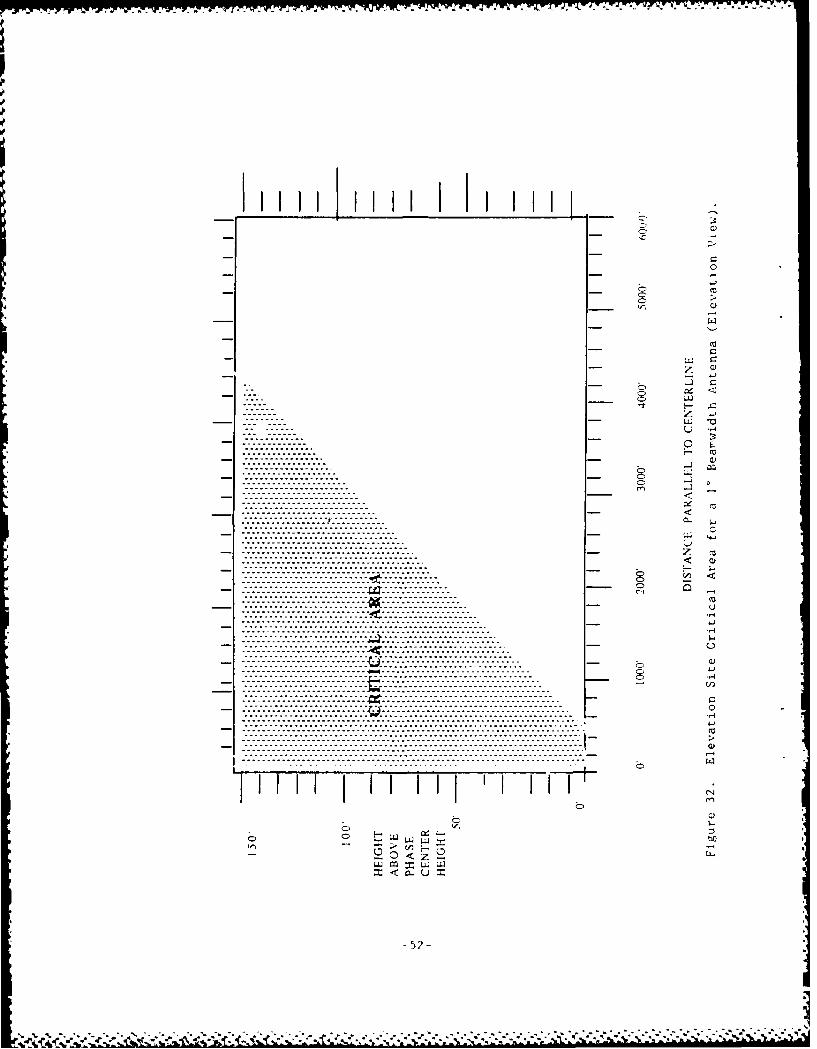
32 Elevation Site Critical Area for a I Degree 52Beamwidth Antenna (elevation view).
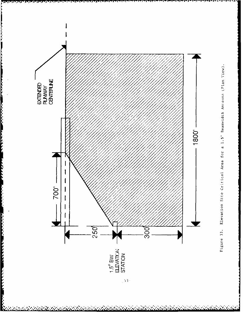
33 Elevation Site Critical Area for a 1.5 Degree 53
Beainwidth Antenna (plan view).
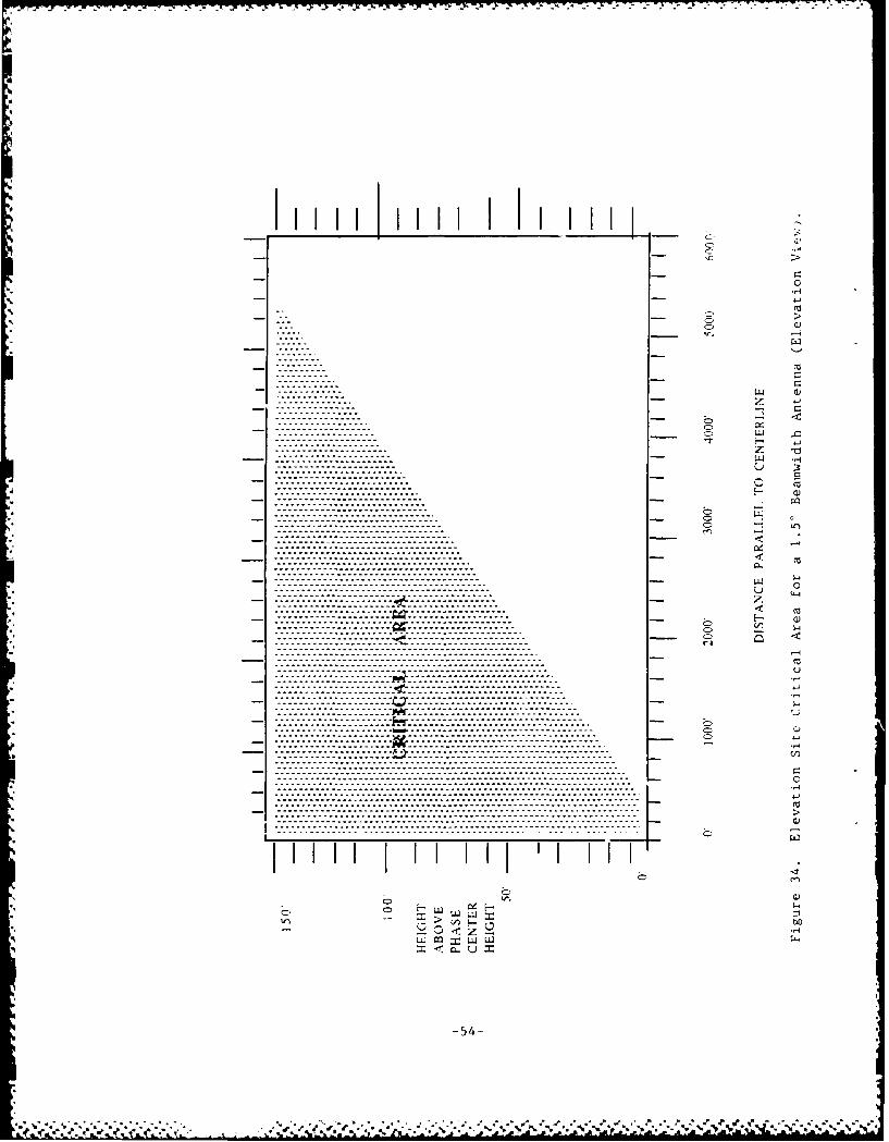
34 Elevation Site Critical Area for a 1.5 Degree 54Beamwi dth Antenna (elevation view).
35 Elevation System Critical Areas Suggested by AWOP -10 55Meet i ig.
36 Transitional Surfaces. 56
37 Ray Tracing to Determine Multipath Region (plan view). 57
38 Ray Tracing to Determine Multipath Region 59(Elevation View ot Insert).
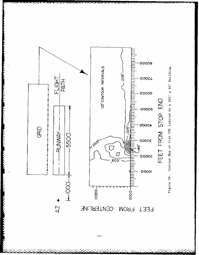
39 Contour Map ot Peak CMN Induced by a 500' X 60' 61Buildi ng.
4o Contour Map of Peak CMN Induced by a 1000' X 10)0' 62Building.
iv
Liisr )F FIGURES AND TABLh;S iii i .i )
'.5
Figu r Page No.
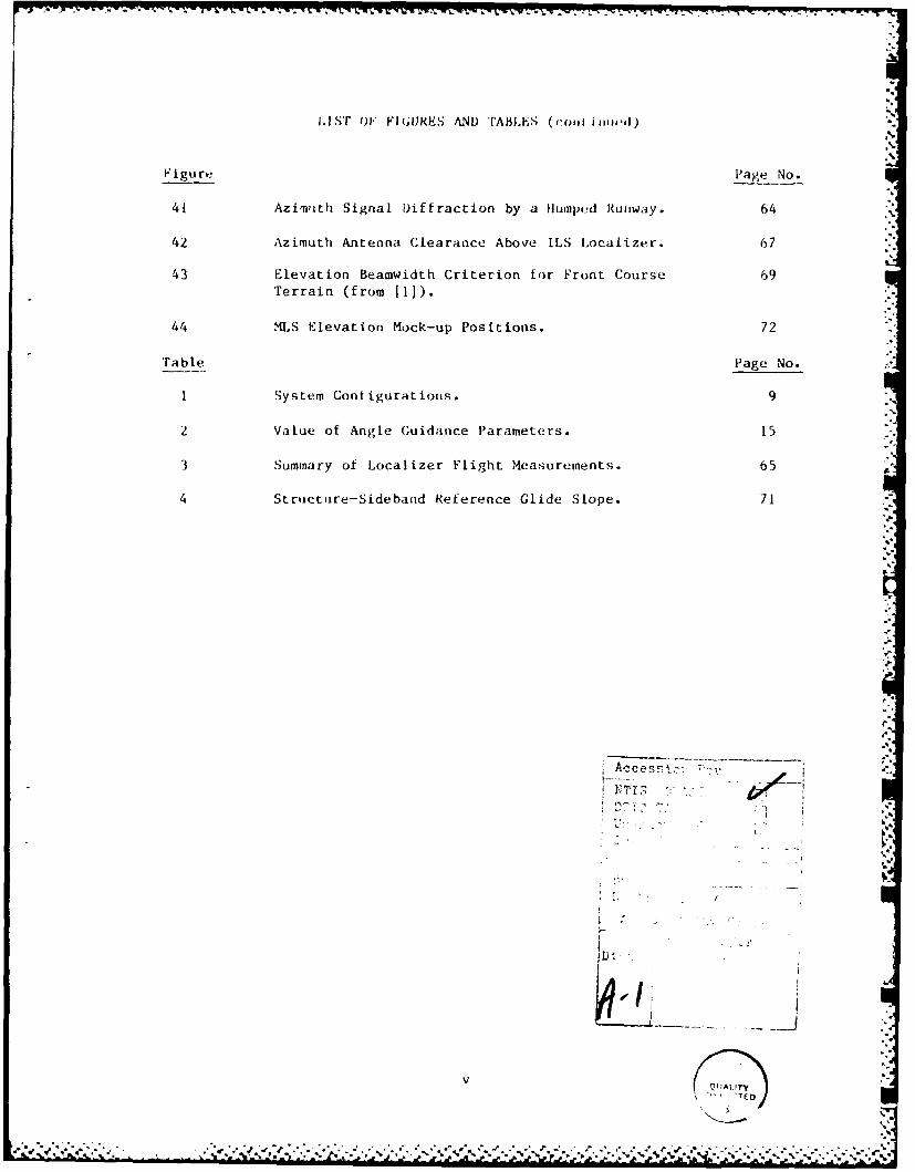
41 Azimuth Signal Diffraction by a Humped Runway. 64
42 Azimuth Antenna Clearance Above ILS Localizer. 67L
43 Elevation Beamwidth Criterion for Front Course 69Terrain (from 111).
44 MLS Elevation Mock-up Positions. 72
Trable Page No.
1 System Configurations. 9
2 Value of Angle Guidance Parameters. 15 .
3 Summary of Localizer Flight Measurements. 65 A
4 Structure-Sideband Reference Glide Slope. 71
ED.
a,
U>,,I:
ID#
V, T13 : .,
' |'
CHAPTER i INTRODIICT ION
1. PURPOSE AND SCOPE. The intent of this docilmnt Is t o present ton the
reader the siting criteria established for the Microwave 1Landig Sv tems(MLS) . Use of the KLS computer model, data gathered from sm'ilalI measure-ments and testing, and insight gained from past work with t10 InstrumentLanding System (11,S) have contributed significantly to the dovelopment ofthis document.
Incorporated in Chapter I is a brief presentation of the background of theK4LS along with the rationale for its development. Chapter 2 begins with ageneral discussion of XLS and its theory of operation, as well as itsgrowth potential and operational capabilities. Chapter 3 is devoted to MLSpower and site preparation requirements. Chapter 4 introduces a general
discussion on topics germane to siting, such as critical areas, multipath,and shadowing. Chapter 5 discusses basic siting criteria, and finally,
Chapter 6 is concerned with specific criteria developed from the analysisof propagation anomalies (multipath, shadowing, etc.), and a discussion ofcomputer modeling to aid in siting.
2. BACKGROUND. The concepts of the Microwave Landing System date back tothe early 1950's. From this time it has seen various improvements,electronic scanning and solid state digital electronics to name two, which
have contributed to the development of the present day MLS.
MLS is designed to be an all-weather precision approach and landing system
capable of meeting accuracies equivalent to ICAO category II standards
([1. MLS operates with an internationally standardized signal format.Thus, any aircraft equipped with a standard MLS receiver can make a guidedapproach to any MLS-equipped runway. MLS also offers a large volume ofguidance coverage, which allows for segmented as well as curved approaches.This is desirable for noise abatement or other special conditions. MLS
also provides a continuous ground-to-air data link to the aircraft. Itsmodular design makes it flexible and capable of meeting the needs of indi-vidual installations.
3. RATIONALE FOR THE DEVELOPMENT OF MLS. MLS overcomes the singleapproach-path limitations of ILS, and can provide improved approachguidance, meeting requirements predicted for the foreseeable future. It isestimated that a minimum of 100 channels will be needed if the predicted
channel congestion Is to be avoided [2]; MLS can provide 200 channels [3].
The MLS format can provide proportional guidance over a maximum servicevolume of ±62 degrees in azimuth and up to +30 degrees in elevation, per-
mitring segmented and curved approaches, and a selectable glide angle [4].(Typically proportional guidance will be ±40 degrees in azimuth and +15degrees in elevation.) This capability allows the selection of 3pproachprofiles that best fit the performance capabilities of the aircraft, maxi-
mizeq the number of approach aircraft by making possible a more efficientuse o! approach airspace, and enhances noise abatement by allowing spe-
cialized approach paths which avoid nearby communities.
---
Kinpio 1'ib -* ilcrowJ f rftt ti -t ;11 lowi MIS, lilt hetn, to , I tot- roll [cal [y"I4IrgE 41u ruliig relaiti VelIy sInaI 1-h'. II ly. - i!'l ;iterttire
ant- I'Il j r,-- I v-- iit tIla t ur.' (,! I ab I I -;It aI Ill r row ltt.ltfl i I Tcht . 'lulia rae( toe r I,- t I I ; Oct he( use d by lte s I tI ng el),Ig! o t - r t o it) I It I t 7. Ili, ;ilmu it of
reF la-ct eel RV -i-r> frun hanigars, atirport hi Idtigs , aind a ir r ot it tii fluE-
ground.
9%Digi ,;i I si~n process ing nay be Incorporated in the IlLS r.e i -,/(r to reducethe eF fects- of -itil I Ipath, alonig wi th the capabiIi ty to recei ve datai. Suichi nforma t ioni as :1/ [matth angl e of [set , runway beadi ng, prec ion distanice-measkur i ng eq u ipmnt ( DME/ P) of fset , and ci eva t ion ante nna he I ght (.,an hetransrui tted 11o the- airc raf t continuously via dat ilink.
UnIi ke ILS , 4-US ant .'onas do not rely upon a large ground plane to establ ishthe si goal In spac.-, anud Urnis MLS is less vulnerable to terraini effects.This; tict , plus theilal physical size of the IlLS antennas, allows moreI lox! ililty and reduced ctsin sitinig.
Throci;'itic- cct dii ' i design and miicro~wave RIF frequencies, MLS cantr'tvidlie he Ii low ing:
-lie r.-aisod operat lonal I cipa-bi lit ies-high rotlahiIi ty-cx eltent- signial quality and guidance-tile flexibility to meet difficult siting requirements
CIlAPTIKR 2 DESCRIPTIiN OF 'I1S
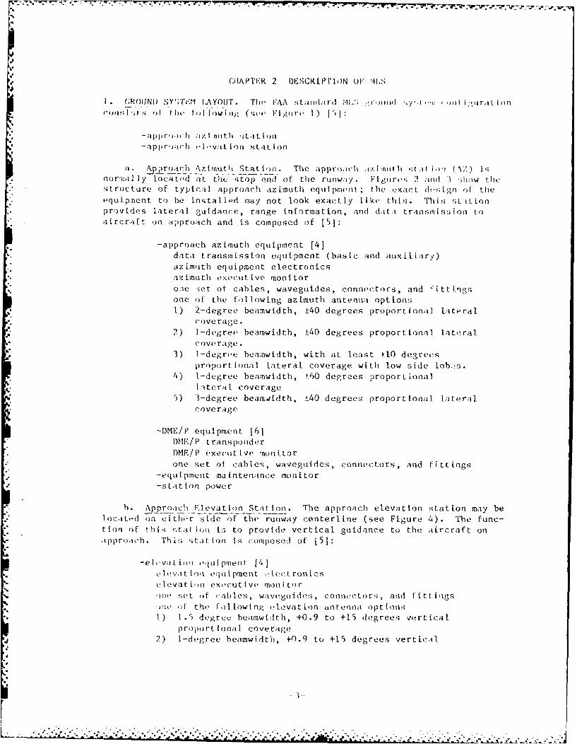
I (;R01IN1) S.Y';ri.V lAYOUT. 'h, FAA sta;ndard MI,:; yrm.d y (.t wf i ,uraLi on1'fn0 jl; 1; of I1)1 fl lowing (set, FIgiurie 1) 1')]:
--ap1 r,);cih ,Iv;t lon stat ion
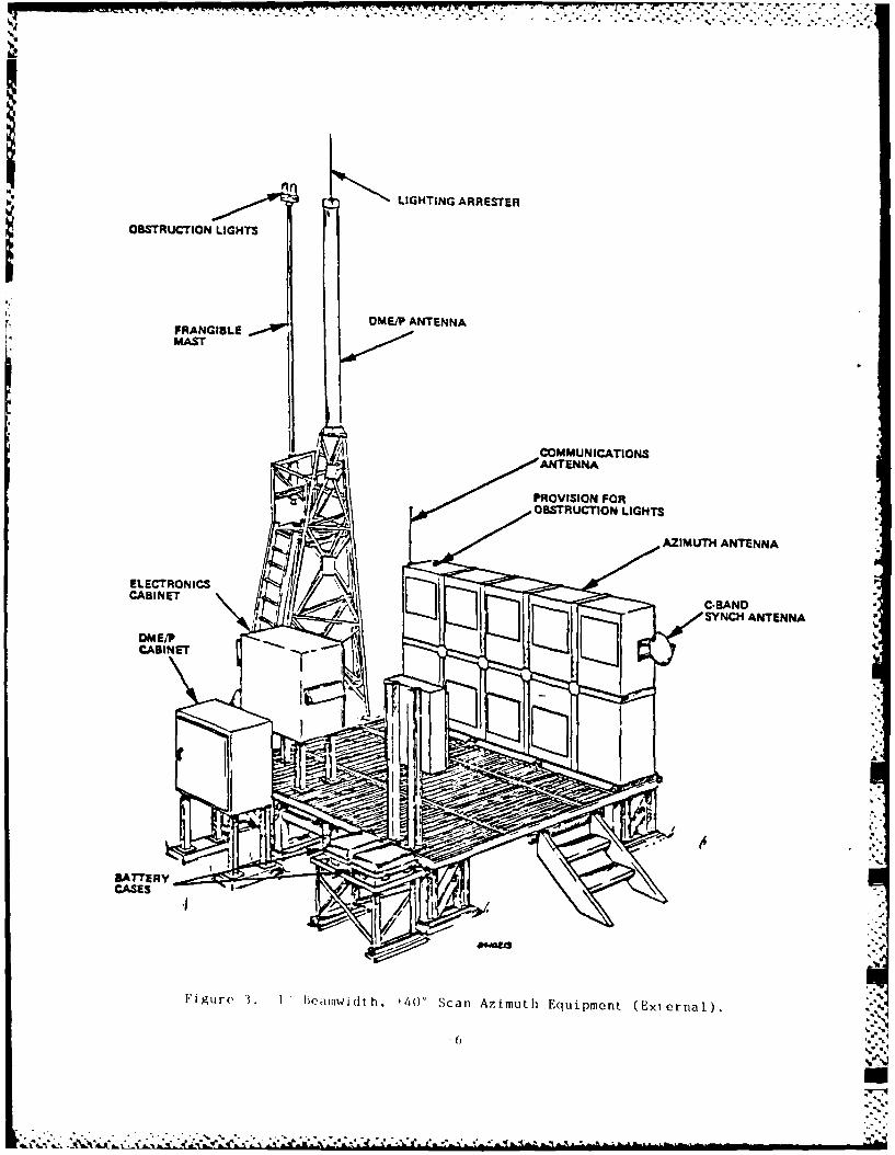
a. Approach Azimuth Statiti. The appr).ich ,izinluthii sL it o (i, ) isnora[ial ly loat t th stop end of the runw;iy. Figures 2 ;an( I .how thestructure of typical approach azimuth equipment; the exact dsIgn of theequipment to be installed may not look exactly like this. This st iLionprovides lateral guidance, range information, and dat.i transmission toaircraft on approach and is composed of [5]:
-approach azimuth equipment [4]
data transmission equipment (basic and auxiliary)azimtth equipment electronicsaimuth executive monitorone set of cables, waveguides, connectors, and fittingsone of the following azimuth antenna options1) 2-degree beamwidth, t40 degrees proportional lateral
coverage.
2) 1-degree beamwidth, ±40 degrees proportional lateral* c ove rage .
a 3) 1-degree heamwidth, with at least _-10 decrees
proportional lateral coverage with low side lobs.4) 1-degree beamwidth, t6O degrees proportional
lateral coverage5) 3-degree beamwldth, ±40 degrees proportional lateral
coverage
-DME/P equipment [6]DME/P transponderDME/P executive mnitor
one set of cables, waveguides, connectors, and Uittings-equipment maintenance monitor-station power
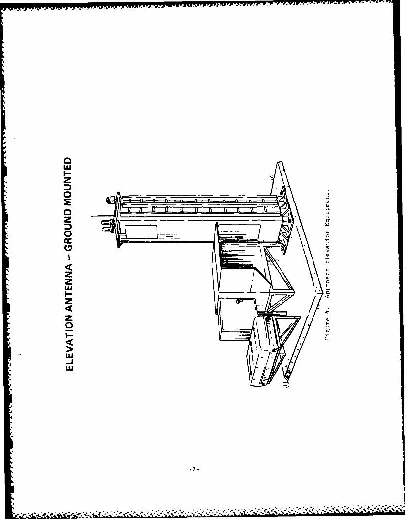
b. Approach Elevation Station. The approach elevation station may belocat,-d on either side of the runway centerline (see Figure 4). The func-tion of thi, tLation is to provide vertical guidance to the aircraft onapproach. This station is composed of [51:
-elevat L oq equipment [41ci ,vd t [in eqtui pment "Iect ron1cselevation executive monitor,)n, set of cables, wavoguides, connic tors, and fitt.tlgs
% )Te Of the following elevation antenna option-. 1) 1.5 degree beamwidth, +0.9 to +15 degrees vertical
proportional coverage2) I-degree beamwidth, +0.9 to +15 degrees vertical
UZ
CC.W6~16
a. 4-i)
00 us
*a z
UA U
'44
ul m
CCI-
-4 -4mt>'U-
I-- a
b-I
C9C
caacC
v.41
-404
WAb
-pM
N1 CNI
P44
CZ1
LIGHTING ARRESTER
OBSTRUCTION LIGHTS i
FRANGIBLE ~U MI NENMAST
4 COMMUNICATIONSANTENNA
PROVISION FOROBSTRUCTION LIGHTS
AZIMUTH ANTENNA
CABINET I
SYNCH ANTENNA
CASES
Figure 3. 1 beamwidth, 140' Scan Azimuth Equipment (External).
--
z
0nno0
zL
proporLional coverage3) 2-degree beamwidth, +0.9 to +15 ulegl,,; v,,rl iciI proportlonal
Sovr rage
-equipment maintenance monitor-station power
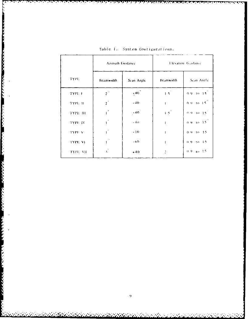
Table I lists combinations of the azimuth and elevation optimi acCordingto the types defined in the initial production contract.
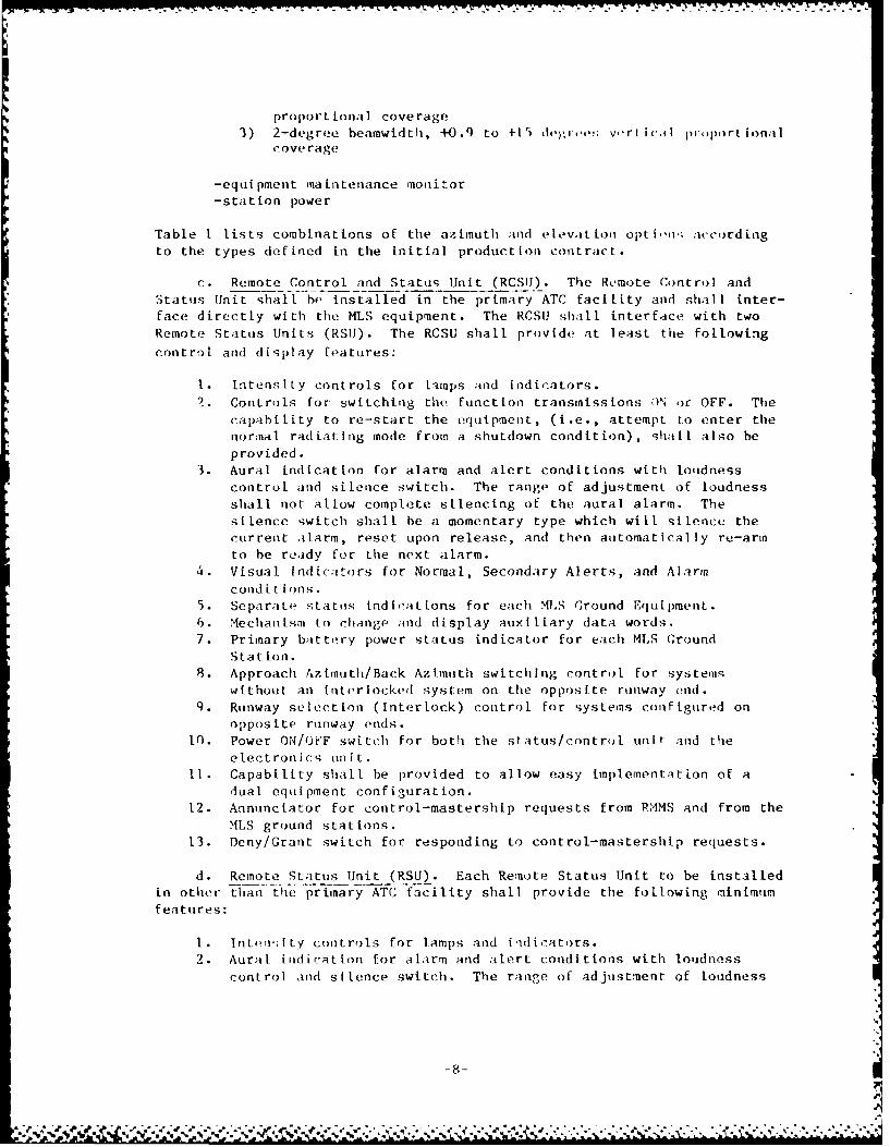
c. Remote Control and Status Unit (RCSIJ). The Remote Control andStatuis Unit shall he installed in the primary ATC facility and shall inter-face directly with the MLS equipment. The RCSU shall interface with twoRemote Status Units (RSIJ). The RCSU shall provide at least the following
control and display features.
I. Intensity controls for lamps and indicators.2. Controls for switching the Function transmissions ON or OFF. The
capability to re-start the equipment, (i.e., attempt to enter thenormal radiating mode from a shutdown condition), shall also beprovided.
3. Aural indication for alarm and alert conditions with loudnesscontrol and silence switch. The range of adjustment of loudness
shall not allow complete silencing of the aural alarm. Thesilence switch shall be a momentary type which will silence thecurrent alarm, reset upon release, and then automatically re-armto be ready for the next alarm.
4. Visual Indicators for Normal, Secondary Alerts, and Alarm
conld i t i ons.5. Separate status indications for each MLS Ground Equipment.6. Mechanism to change and display auxiliary data words.
7. Primary battry power status indicator for each MLS GroundStat ion.
8. Approach Azimuth/Back Azimuth switching control for systemswithout an [nterlocked system on the opposite runway end.
9. Runway select[on (Interlock) control for systems configured onopposite runway ends.
10. Power ON/Or'F switch for both the status/control unit- and theelectronics unit.
I1. Capability shall be provided to allow easy implementation of adual equipment configuration.
12. Annunciator for control-mastership requests from RMMS and from the
MLS ground stations.13. Deny/Grant switch for responding to control-mastership requests.
d. Remote Status Unit (RSU). Each Remote Status Unit to be installedin other than the primary ATC facility shall provide the following minimilmfeatures:
1. Into';I ty controls for lamps and indicators.2. Aural indication for alarm and alert conditions with loudness
control and silence switch. The range of adjustment of loudness
-8-
--F V-W W".-. -" -: ": -
1db!1) 1I S y st cm Co i I i u rat io i is
TYPE Bearmwidth Scan Angle Beamnwidlh ScLin Arn.!ie
fyp +40' 0 S t9 I5'
1 YPL 11 2 40 0 04) to I5
TYPEII 11 .-40 1, 0n to IS
TY P! I 1 4() o1 t o 1 5
TYP'E V 10 0 9to 15
TYPE, VI 1 .00 101) to I
TYPE) VII +40 ' 0
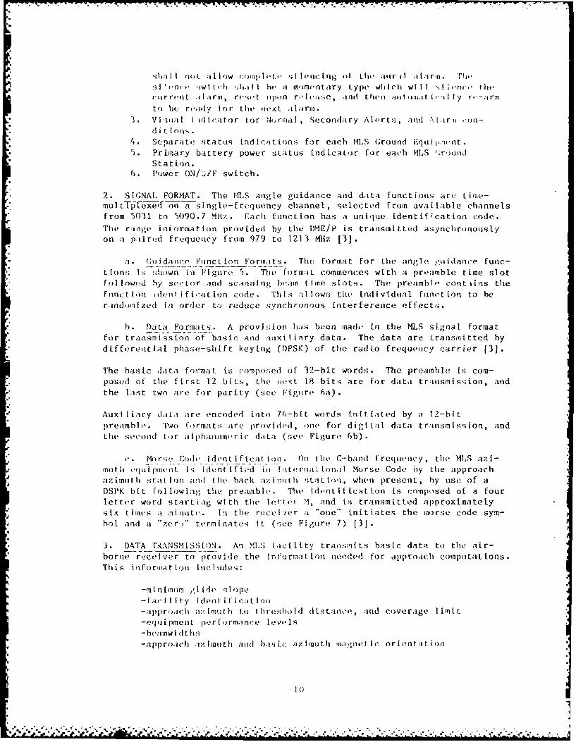
I I nOL al IIOw (:(il lit. si I enc ing o I th i ir ii I aa ill. Thss ri 4, ;w t ch li.il I I hi a momentary type which will ,If1 ernc thecrirreot ii arn, resit uipon roie;1 se, inid then autot'it jI ly r4e-armto I)( ready for the next .itltrm.
3 V VI sie1 11 id(,;I ao r t or N(, riia I , Seconda ry AlIf ir ts , ;vnd .'.1. ia on-d i t I om, .
4. Sepa rate, statuos ind ira t ions f or each MLS Ground iqu i j,-ent.5. Primary battery power sLttus indicator for each NILS ;r,)ilnJ
Stat ion.6. Power ONTHlF switch.
2. S IGNA, -FORMAT . The r-lLS angle guidance and data functions are- time-multi~plexed on a single-frequency channel, selected from avaiLable channelsfrom 5031 to 5090.7 Mliz. Eachi [unction has a unique identificatton code.
The ranige information provided by the lDlE/P is transmitted asynchronouslyon a piired frtequenicy from 979 to 1213 M4Hz 131.
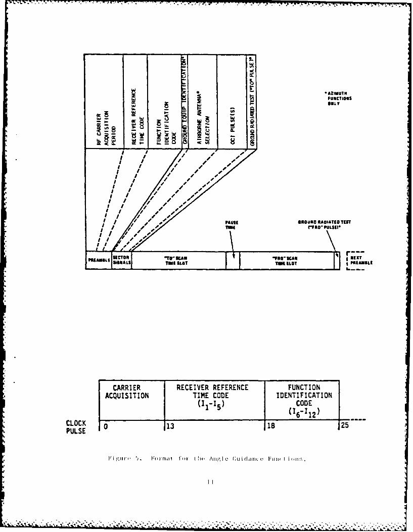
"Ii. Gudance Fninc tion Formats. The formnat for the angle gutiidanice func-t ions 1I; shown inl Figure 9. The form.-ILtcmecswt a preamble time slotfoll1owed by sertor and scanning beam t ine slots. The preamblo- contiins thefilnc t Ion deni f ic-ation code . This a~l lows the individual. fiet ion to heraiidoril zed fin order to reduce synchronous interference effects.
h. Data Formats. A provision ha~s been made in the M~L~S signal formatfor transmission of basic and aurxil iary data. The data are tranismitted bydifferenti-at phase-shift keying (DPSK) of the radio frequenicy carrier [3).
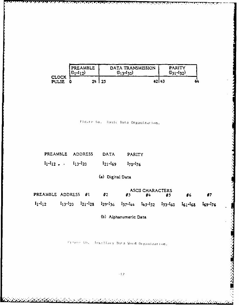
The basic data format is compos;ed of 32-bit words. The preamble is comn-posed of the first 12 bits, the nextL 18 bits, are for data tranismiss;ion, andthe last two are for parity (see Figure 6a).
il AuxitIiary data ;ire encoded into 70-hit words [nti ated by at 12-hit
preamb] i' . Two [Irma ts are provIded, one, for digitLal data t ransmiss [on, andthe second fo r alIp hantine r ic data (see Fi gu re 6 b).
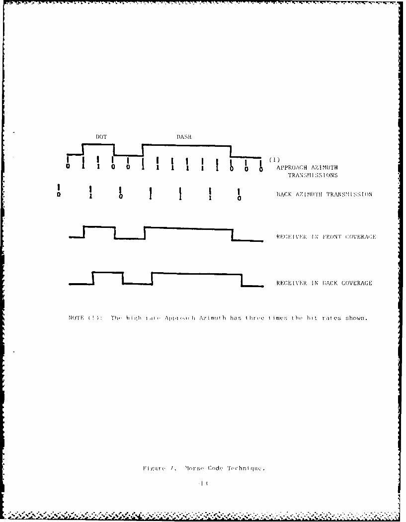
0 . Mn r' Cod1 & [dent I f ic a L i oin On thle C- band f requenc'y , thie MLS az i-muoth Ii uI pine n t 1,; Idernt 1ffed in int ernii I ona 1 Morse Code by tile approachaz imu th sftt I anad t he hack ax i 'Tilthi stat toni, when present , hy use of aDSP'K ht Fol lowing the preamnble. The Ident icat ion is composed of a fourletter word startinig with the let t.' M, and is transmitted approximatelysix times a ninut' . In the receiver a "one*' initiates the morse code sym-hol and a "zerY'* terminaties It (see Figure 7) [3].
3. DkTA TiRANSMiSSI ON. An MLS facility tranismits basic data to the air-borne recei ver to provide the InflormatLion needed for approach conpkutat ions.This informa i on inclI ides:
-ml n mum glidie qlope-far 11.1 y ident if i cation-a ppiroach a; i muth to thire sholId distance, , and cove rage liit--eq ii pment per formaince levels-beaimwidtlis
* -approach ax Imutli and baisic az imuth inaiietic orientat ion
10(
ii.
Ifll' y o,I euuc1Iou
ONLY
I- I -
____ s__ sS
4I
I Ile
I I i / s -
I J /I /I / Is
IAUSI GlOU IO TEST
TIME "NIF PULSW|
I 0 r,
"tABI L. WA / -
SGATILE JLOT TO RLOT IPRAMBUlLE
CARRIER RECEIVER REFERENCE FUNCTIONACQUISITION TIME CODE IDENTIFICATION
(I ICODE(12"Is (is012)
CLOCK 0 113 T2STPULSE
I~i,'li ' '.. Fo(r-mat t ()I- I h1o Ang.le(_ (uidamll e l"un1c-tioTnn.
|y
PREAMBLE DATA TRANSMISSION PARITY
CLOCK 12 (113-130) I (131-132)PULSE 0 24 2.5 42 434
0i au ha s~ 8 i c Da t a Organ i zat i onl
PREAMBLE ADDRESS DATA PARITY
11-112 *. 1134120 121-169 170-176
(a) Digital Data
ASCII CHARACTERSPREAMBLE ADDRESS #1 #2 #3 #4 #5 #6 #7
11-112 113-120 121-128 129-136 137-144 143-152 153-160 161-169 169-176
(b) Alphanumeric Data
'i' -v D" Ta 'W d 01-ID glfnl/.dt i on.
I-. -.. ~ . . . . * -. *. * * *
. . . . . . . . .. . . . . . .
DOT D)ASHI
0 0 APPROACH AZIMUTHTRANSMI SSIONS
I I I hBACK AZ I NUTI 'rRANsM I SSION
RE;F; kIN FRONT COVERA;E:
RECEIVER IN 1BACK COVERAGE
NOTEt Ji ) Th h i ile Appi eni h Azi mut h has 1,hi ele t imes t he hi t i al es shown.
Fi gIl1( I. >Iorse Code Techniqupe.
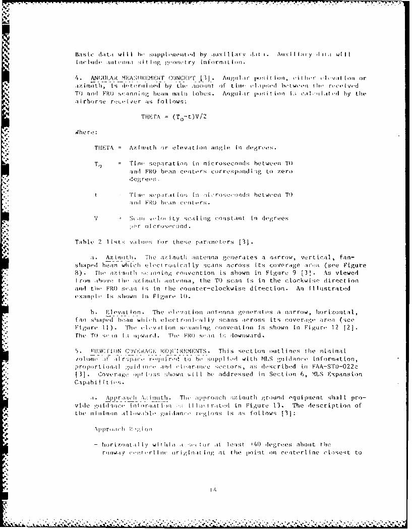
Basic' da t;t wil 1- esup ~uei ' by :lux i liarvI I Aiix i li ;y I ili willit(- I ii uit ennlii ; I I I 'ig )'(')lfl I ry 1 flfo rill.111 )1ll.
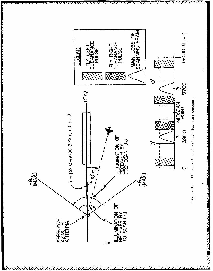
4. ANu;I]iA- - M-1-:;Ii i:I . C NC-Ki'U J . Angii I it p It I in ,it I ir tIt vat Io it or* .liz jah, ts diettrirl ijed by Lt(e .iiiliiit of Lt int, oi ipsed between I lte rece i ved* To and FRO sr:-nni iing beam ma lii lobes. Angul ir p, t ion I.; t7.i I .ilIat od by the
airborne rfeceiver as follows:
THEFTA =(T 0 -t)V/2
~4he re:
ThETA = Az inn t h or ele vat Ion angle iii degrees."
To =Time separat ion in microse condhs between TOand PRO) beam centers cur respond i og to zerod eg rees
t T Time scp-ira L i oii ini iii ros-ond s bet weea Toand FRO bimi centers.
V Sc-ii v,,lou i ty scat ing conlStAilt in degrees;)or in c rosocond.
Table 2 1 i t - V.il1 oe'; to r thes;e pa raine Ic rs 1 31.
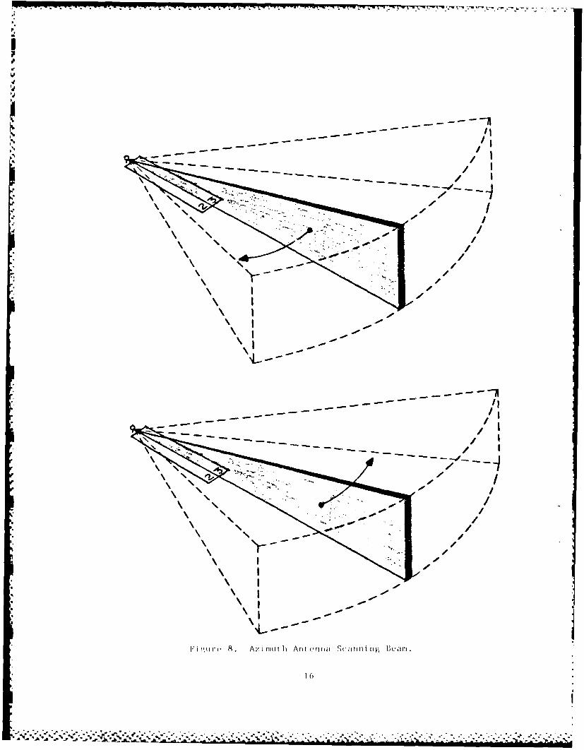
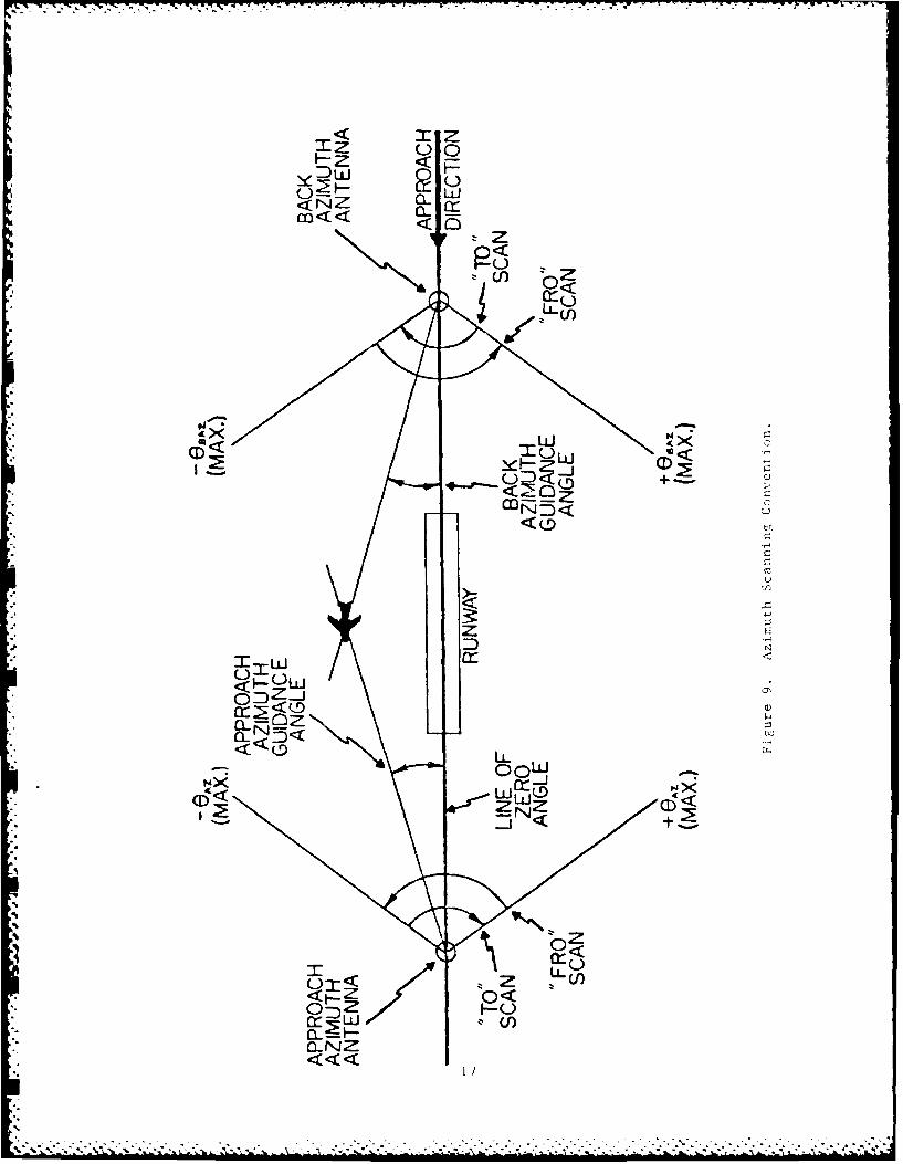
.1 . Az i0liith . The ;iw, ijiuth ;intenina generates a narrow , vert ical ,fan-shaped heaim which elect roaical Ly scans across its coverage areta (see Figure8). Pit, azitnit h sino ifing convent Ion is shown in Figure 9 [31 . As viewedf rom tbove the ;i/.imnitlk antenna, the TO scani is in the clockwise direct ionand the FRO scani Is- In the cotiter-clockwise dire-ction. An iII list ratedOClianplo Is shown li Ftitire 10.
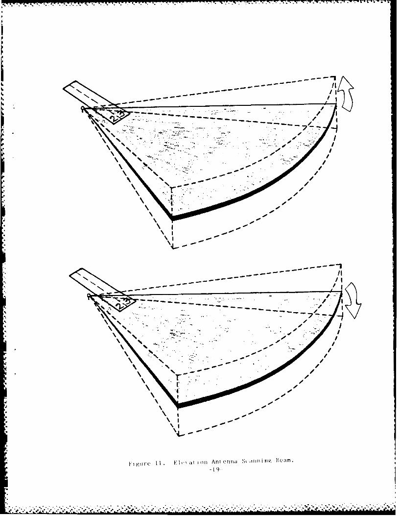
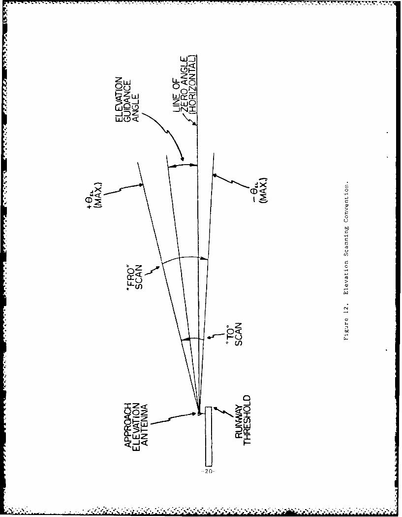
b.. I vva t !on. The r'l cjition antenina generatLes a narrow, horizontalfall shlapedf beoai whic-h elect roni [at ly scans arross its coverdee; are: (seF Iguwre I I) The i-lovit Ion sru:ini ng convent ion Is shown In Fi gure 12 [21.The* TO ;r.inl I.; itlward. 'Tile FROt su;Il iS- downoward.
5 . 'LJNC I' I nN C0VV i<:AGL E t1RhMET. Th is sect ion outlines tilhe ain! -tmal
olnm ofii r;J~ce r([ii re tobe iippl i ed With MLS tguidance information,proport ionail ;goi II lie and ci larince s;ectors, ais described in FAA-STt)-022c
3]1 . Cove rage opt [rmis !shownl , I I b e add ressed in Sectiton 6, MLS ExpansionCa pa b ii ties
.1App~r oa ch A. o t.Thc app)roa ch ;-/. ian th );round oqui pine n shalt pro-vidoe o'o I ncei o -iatim o 1 ct r-tltd in Figure 13 . The description ofthe tiiii imitin al low-ihie, guitiano regoins is as, fol-lows [31:
-horizonta 1 ly wl-thIi ,t ;(- tor .it least #40) degrees abouit thlernw.iy -enft cr1 Int- or igI n-t log al the point on centerline cIsstto
M*.! A2 S:,
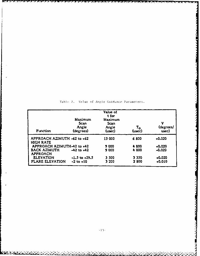
Tahle, 2. Value of Angle Guidanlce Parameters.
Value oft for
Maximum MaximumScan Scan V
Angle Angle To (degrees/Function (degrees) (usec) (usec) usec)
APPROACH AZIMUTH -62 to +62 13 000 6 100 +0.020HIGH RATEAPPROACH AZIMUTH-42 to +42 9 000 4 S00 +0.020
BACK AZIMUTH -42 to +42 9 000 4 300 -0.020APPROACH
ELEVATION -1.5 to +29.5 3 500 3 350 +0.020FLARE ELEVATION -2 to +10 3 200 2 800 +0.010
del5
* ~...........................................................................
po
.16
Iz
C) LLC
IF Z
P<O
UC
wwQ~L....Jc. C
M(-)CO
zC
,"FaXD
Iz
cr-N
1/
.....................................
LiL0<
W i
z _L<nQ)<c _ 0
w -jcc-j rrr z 0(9 <D <)z z -0
LL-i L-J() E
0 01
N
Z
00 '-- a.
cio
0 0
o
CD~ -
C))
18-)
IN
I4
r-
Li irc C 1 .t I i at o A n ei t enn i t i n c i em.
-- j 22L
W-J<(5-L
ZL±J LL<OLD c() 0 _
HZLU 0O-JNI
.JDZ
LzJ00
4u
*ax < 0,-r cc
+ a)
o<bOo
"-4
Q))
0<< e)uc~U)
6 4;
-20-
,...'*~ ~~~~~ ~~ ~~~~~ .. . . . . .'% * . . *.. . V ' .*****.*.*.*****.**

20" -- - - -- CIL
45rn 00111)APPROACH7 DIRECTIO
(o) HORIZONTAL COVERAGE
6,0O0m CZ,0OOft)--
2.(b) VfRICA COVERAGEA
Vi) lir I i. Approach Ax'i niur h/Dta (Coverage.c
%. -- 1
the t'(lova tiI )11 n l .inia phase center (tIthv MI..s dai tim i pt I ii) .vit Ie t(en(ling [i lhe directl on of .pproirh it) ?() iilll| .'.,l iii I,.a. Ir .isystmn providin, I .0 dogro lateral 'oVe.itl , t lie It, 1|)',' IA-4 relliem ii
Is roducini lo 1.4 na.utical mIles beynl Lih' 14) d&.)"Io, .ci :ii lr
(C OVE' rage_1.
- vertictally betwefin conlic;ll surface-, which orl),iato on i v rl ic.l
Line passing through the MLS datum point, of which:
(I) The lower surface crosses threshold at 2.5 meters (8 ft.)above the runway centerline ncinmed at 0.9 degree above
the horizontal
(2) The tipper surface crosses threshold at 600 meters (2,000 ft.)
above centertine inclined at 15 degrees above the horizontalto) a heig, ht of 6,000 meters (20,000 ft.).
Runway Region
- orizont.lI within a sector 45 meters (150 ft.) each Lie of therunway centorline beginning at thte stop end and extendi:ig parallel
with the runway centerline in the direction of the approach to
join the approach region.
- Vertically Between
(1) A horizontal !;urface which is 2.5 meters (8 ft.) abovethe runway centerine avd;
(2) A conical stirface originating along the centerline
extended beyond the stop end of the runway which crossesthe stop end at 150 meters (500 ft.) above centerlineinclined at 20 dogrees above the horizontal to a heightof 600 meters (2,000 ft.).
Proport.onal Guid anc
- Prop ortional guidance shall h provided iii the runway regionand in a sector of at least 10 degrees about the runwayceaterli.ne extended in the approach region.
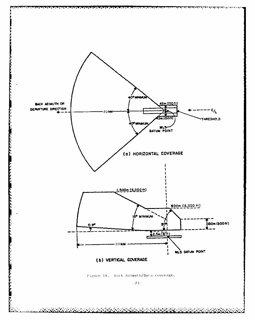
b. Back Azimuth. If azimuth gidance Is desired for missed approachesand departnre guidance (back aztimth), it will he provided by a standardMLS located at the opposite end of the runway with Its preamble and time
slot changed accordingly. This back azimuth shall supply guidance infor-mation in the region shown In Figure 14. The minimal guidance volune per-mitted is a:, follows [3]:
Missed Approach/Back Az imuith Region
- Hlorizontally In the back azimuth region within a sector '40 degreesabout the runway centerline originating at the MLS datum point and
-22-
-. ... _ -
BACK AZIMUTHf OR 5"1
DEP6RTLIRE DIRECTION I -
2 0 M M - 5 m ~ o ftT H R E SH C (..D
Daum PO00INT
(ba) VORRTOCAL COVERAGE
II
a. *. . .. -a
a.0N
~*,****IALS* DAU POW
'xt,,n (I i o, I I tht ' 114 re l Iin ,1 mI! seI ,pproch a i t I tf, I , 20 1lkiil I-(aI in!I Ie'.
- Vert Ica I ly In tIw back ;i. In it i regIon ntw n c1)l lca I ;1rf w,-;which originate on a ve rLi(al line passinlg thiroi'la t Ci J ; A I,. , '
poilnt, of whi7hl:
(I) The lower surface crosses the stop end at 2.5 fet., (f tt.)above the runway centerline inclined at 0.9 degre, ihove thehorizontal;
(2) The upper surface crosses the stop end at 600 meters (2,000 ft.)above centerline inclined at 15 degrees above the horizontalto a height of 1,500 meters (5,000 ft.).
Runway Region
- lorizontally within a sector 45 meters (150 ft.) each side of therunway centerline starting at the threshold and extending parallelwith the runway centerline in the direction of the stop end tojoin the Back Azinuth region.
- VertIrally Between:
(1) A hurizont-il surface which is 2.5 meters (8 ft.) above therunway centerline; and
(2) A conical surface originating along the runway centertineextended beyond the stop end of the runway which crosses thestop end at 150 meters (500 ft.) above centerline incline at20 degrees above the horizontal up to a height of 600 meters(2,000 ft.).
Propor t ional idance
- Proportional Guidance slhall he provided in the runway region andin a sector ,)f at least u1( deg;rees about tile runway centerltneextended in th, back ;iz mth region.
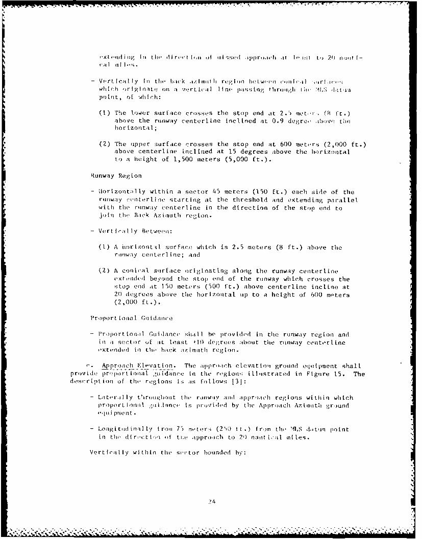
. Approach Elevation. The approiah elevattoyi ground equipment shallprovide pr,)portional guidance In the region; iltstrated in Figure 15. Thedescription of the regions is as follows [3]:
- Later.illy throughout the rkinway and approach regions within whichproporLtinnal .iilance Is proviled by the Approach Azimuth gr)undo i i pmrent•
- Longitdminally froui 75 metersi (250 ft.) from the MS datumi pointin the dir-c(ti: io of tkae approach to 20 nautical miles.
Vertirally within the s(etor bounded by:
)4N A
.................................... S. IA -
-
. . . . . . ..
145M (150ft) MINIMUUA SECTOR EQUAL TO
~~~PRPmTA (10MAoe~it JDANCE APPRAH75m 150 f) DIECTION
(a) HORIZONTAL COVERAGE
6,OO0M (2O0,O000ft0---
cc - - - - - ORIZONTAL
(b) VERTICAL COVERAGE
Fi ,'ure 15. Approici I. Iv I I i oi Coverage
- A sirf ic'' wlib-Ii Ik ti I,)(-, i t I poI nt 2.) it rs (0i If .) I") vo .
tIle rllrlw.iy;
- A crtii Cal ;,rf.ic iiri'iniit icfl' at the lMLS dittim pl nt llitl i -1 iuiid
at 0.9 del;re above tlii, h lr toiLrilh; and
- A conical sutrface origia? 1mg at the MLS datm point ri'! inc lined
13 degrees above the horiz)cit,il up to a he ight of 6,0') mioters
(20,000 ft.).
d. Data Coverag t. Basic data liall be transmiitted thtrouhit the
Approach Azimuth coverige region (words 1-6) and tile Back Azii ti coverage
region (words 4, 5, 6).
In tht absence of Back Azinuthi, ai,.I'llary data words Al, A2, and A3 shallbe transinitt ed tirough' iL tile Appri.tch Azimth coverage region. However,
when Lhe Back Azinu tl cove rage is Itesciit, atixiliary words A3 and A4 shall
he trtilso i tted tlhrorg/hokt botAh tile Approach and Back azimnuth c(fc ' rage
reg ios
e . DM12 P. lDIE!P coverage sh,ill be oiii hitrect ional as shown in Figure
16. Coverage will be provided it all azimuth arie,-ls and angl-s of eleva-
tion between +0.85 degrees to a miniinim of 15 degrees relative tLo the
DME/P antenna phia;e center aid up Lo heights of at least 20,000 ft.
6. MLS I.X PANS (;AP.B IT, I[ES.
ai. Dual Mod Azi-uth Antennia, . The 1M1,S ax i-mith antenna is capable of
supplying e-it her riop ronch rr back --;tz ith fuieti on. This function is
gener ilty imp eon*n ted whrei two complete sets of MLS ground equiipneit areused to serve the same runway. The MLS equipment is configured so that
bothI ends of the runway are Lippled with precision approach go idance
(i.e., dual aziitith airtnuas, DME/P, and an elevation station at each end
n f teie riliw.iy) . iHwev,2'r, ther', ikS a period diirinLg tire switching of the
syste".... cc'clfpri i'n whenl ,n ,M1.S gkdce Is avaltable. This period wilLhe no ,;rc'it er tinac 30 s'conds.
b. A'cs:iliwiry ta., IlLSq 'a prlvid,' I, r tr-ins-nissionl of idditional
anixt i ry dit.i. I'iis fe iLure na in, hide mnerorflogical information, run-
way s t i'is, and wi,il ';eIocities. The exacr con tealt of the additional auxi-
liary data l.-is .lot been Lndir lized at tiiis time.
C. "36_ Degrc' r \Az i t! 1 1 h. Tim,' Is re;erved in the MILS format for 360degree azim,th W'ic)_rig&' *tcd t1 ri ricLion is being considered.
d . t1, it t (S','d i AztI. t!ilCo veroe _.e MS can al.3o provide noa-syumefrtcrl Ainltl -cv,<r i . i ex ipi e of thi feature Is 1O degrees
propcrt on;il )iI ,i,' on .: :itI: cf tihe runway rind 40 degrees on the
otlier. Th is fe.i cit ' cani b., i;.-l tr, reduce nil t ipath reflect ions caused by
ohjen I s ciose o,. in,'f 1.1,i ;'curway without ;acriflctg coverage on the
other.
e >c
., - '- € . - . . 7o .. .. . .. .. .. .. .. .. 7." - '" ,'"€ , ;'Y" r - - r7. "'' Y:'"' ' "- . ".--" ". '.-.' 7 '""
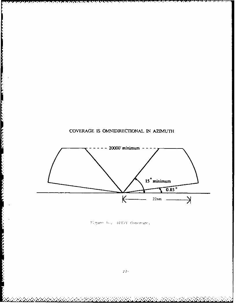
COVERAGE IS OMNIDIRECTIONAL IN AZIMUTH
0.850
K - 22nm m
2urr 1' I1/1 coverwirr'
* 27-
.. ZL L~2~ 1.~d ' " '9 .. '9AA
CIIAPI1'R 3 INSTALLATION EQUIREMENTS
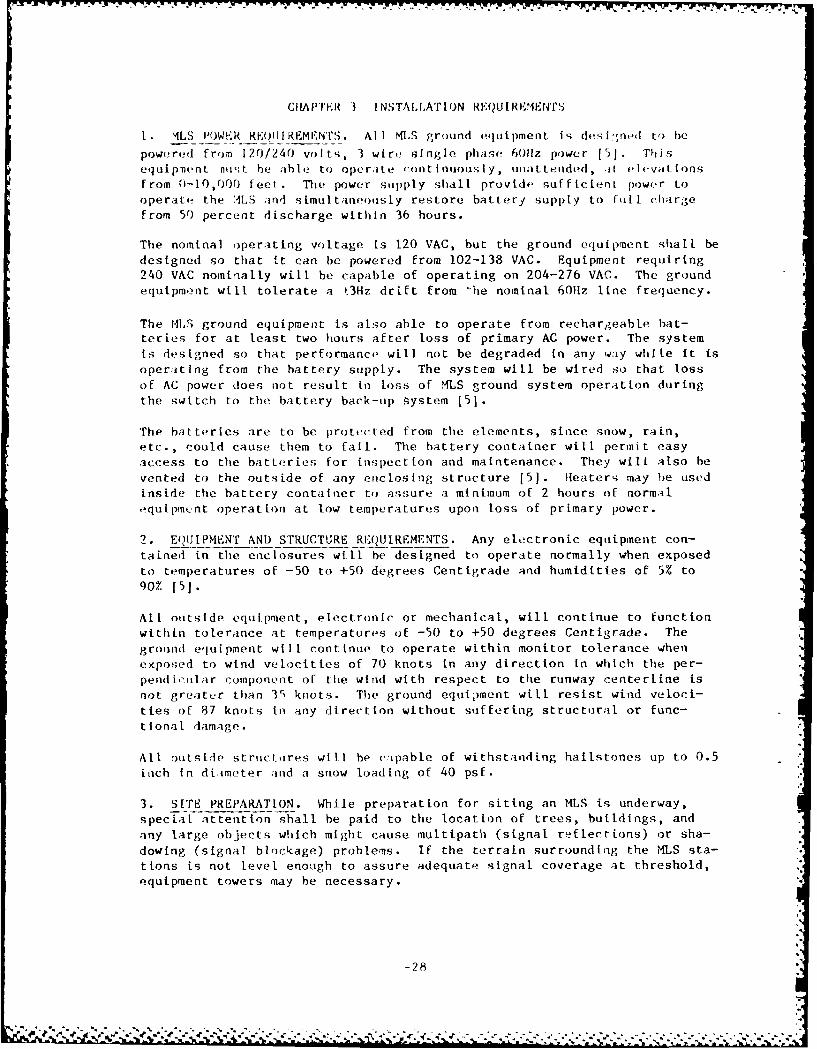
L. %LS !OWF.R RE0IJIREMENTS. All MLS ground eqluipment is desi:.ned to be
powered from 120/240 volts, 3 wire' single phase 6011z power [5]. Thisequipment nivt be able to operate continuously, unat teded, it ielevationsfrom 0-10,000 feet. The power supply shall provide sufficient power tooperate the 4LS and simultaneo)usly restore battery supply to Fll chargefrom 50 percent discharge within 36 hours.
The nominal operating voltage is 120 VAC, but the ground equipment shall bedesigned so that it can be powered from 102-133 VAC. Equipment requiring240 VAC nominally will be capable of operating on 204-276 VAC. The groundequipment will tolerate a t3Hz drift from -he nominal 60Hz line frequency.
The ML. ground equipment is also able to operate from rechargeable bat-teries for at least two hours after loss of primary AC power. The system
t-- designed so that performance will not be degraded in any way white it isoperatlng from the battery supply. The system will be wired so that loss
of AC power does not result in loss of MLS ground system operation duringthe switch to the battery back-up system [5].
The batteries are to be protected from the elements, since snow, rain,etc., could cause them to fail. The battery container will permit easyaccess to the batteries for inspection and maintenance. They will also be
vented to the outside of any enclosing structure [5]. Heaters may he usedinside the battery container to assure a minimum of 2 hours of normal
,*quipmcnt operation at low temperatures upon loss of primary power.
2. EQUIPMENT AND STRUCTURE RIEQUIREMENTS. Any electronic equipment con-
tained in the enclosures will be designed to operate normally when exposedto temperatures of -50 to +50 degrees Centigrade and humidities of 5% to
90% [5].
All outside equipment, electronic or mechanical, will continue to functionwithin tolerance at temperatures of -50 to +50 degrees Centigrade. Theground equipment will continue to operate within monitor tolerance whenexposed to wind velocities of 70 knots in any direction in which the per-
pendi,,tilar component of the wind with respect to the runway centerline isnot greater than 31 knots. The ground equipment wiLl resist wind velocL-
ties of 87 knots In any direction without suffering structural or func-
tional damage.
All outside structores will he capable of withstanding hailstones up to 0.5inch in diameter and a snow loading of 40 psf.
3. SITE PREPARATION. While preparation for siting an MILS is underway,specIl attention shall be paid to the location of trees, buildings, andany large objects which might cause multipath (signal reflections) or sha-
dowing (signal blockage) problems. If the terrain surrounding the MLS sta-tions is not level enough to assure adequate signal coverage at threshold,equipment towers may be necessary.
-28-
4 . .. 4
It has been shown tI at Inter ference f rom powr I I rg's, tei-s , and a ppr)achlight systems in the far-field of the aiitennas- will be mnmn;I -it the MLS
frequency [71. Unless these st ructures are uniisiz. I ly large, or ( oil,; i st of
very densely spaced conductors, they will not he of concern.
Since ILS antennas rely oil tile formation of an itnage by reflect ion ofsignals from the ground, a smooth ground pla ne is reqlmred sc iral thousandfeet in front of the glide slope aitenna to establish ;in accepi- ble glide
path; this is not the case with MLS.
4. INTERCONNECT REQUIREMENTS.
a. Power. When site engineering commences, provisions arl to be madefor 120/240 volt single phase AC power to be supplied to all MLS ground
equipment. Power for approach lighting and the azimuth station are to bekept independent of each other. Transformers must be kept out of the
obstacle free zones.
h. Commuications. A communications link must be provided between allMLS ground equipment serving a particular runway and its Remote Control and
Status Unit (RCSU) and Remote Status Unit (RSU). Communications arerequired for three purposes. One is so that the ground equipmenttransmissions can be synchronized. The second is to provide equipment sta-
Ius to Air Traffic Control (ATC) personnel. The third is to provide datato the Remote Maintenance Monitor System (RMMS). This communications linkmay he provided through any of three media; wire lines, fiber optics
cablos, or UHF/VHF radio link. If wire lines already exist at an airport'nd they are of suitable quality for the MLS data transmissions they shouldbe utilized where practical. Also, the existing lines should have a pro-jected useful life of at least 10 years. If it is determined that eKistingcabl)e is not useable then new fiber optics cable should be installed. Theradio link should be used only as a last resort if a wire or fiberInstallation would be too costly or impractical.
The RCSU c,)nsLsts of two units. One is the control and display panel whichgenerally should h' installed in the local ATC facility (control tower) ifone e ists. If there is no local ATC facility it should be placed in alocation where there are communIcations with the nearest ATC facility. Thesecond part of the RCSU is an electronics unit that sends the informationto tile display panel and also is the interface point for the RMMS.Generally it should be Installed in a location with easy access,; by main-tenance personnel.
The RSU Is simply a status panel that is a slave to the RCSU. It can belocated at any other location where the status of the MLS is of interest.
Up to two RSU's may be installed with each RCSU.
In the situation where MIlS equipment is installed to serve both ends of arunway, a singlo RCSIJ (electronics and display) will control both systems.
-29-
- - * -. - .
d . - -. .
CHAPTI'R 4 GENIERAl. DISCUSSiON OF CONSIDEIRATIONS TIAT AFFE'Cr SITING
t. PREPARATION OF DATA. Before the installation of any MLS ,ul ipniont,
data are to be obtilned to plermIl ovaluation of the runw;iy(s ) h, *(,r-
viced with MIS, as w-ll ;is tho 'Hrrouliding area. These datt , 1ill inclilde,
but a r, not 1Iml,' d to, the fo[lowing items:
-obstruction clearance charts. Siting cons iderat tons m.iv dictate
equipment placement near obstruction clearance boundaries.
-United States Geological Survey (USGS) topographical charts of the
airport irea and full service coverage area for the MLS.
-runways to be serviced with MLS, their lengths and profiLes (detailed
enough to accurately identify runway humps).
-Jescription of existing navaids.
-airport conduit and cable information.
-ground traffic patterns. Ground traffic is not permitted within
specifled boundaries around MLS antennas.
-run-ip and iet blast areas.
-uat,-.ory o iircraft to be serviced.
-4LS typu- proposed and equipment characteristics pertinent to siting.
-airport proptLy lines.
-11.S. instrument Approach Procedures defining existing approach pro-
cedures to the airport and identifying obstacles in the termitnal
ai rea .
FurtLher informition shall also be compiled after discussion with airportofficials, FAA Aviation Statidards National Field Office, Air TrafficService, Airport Service, and Airway Facilities Regional. Divisions. These
consultations wilt provide additional insight into such topics as:
-existing and future traffic patterns. An MLS sited without consider-ation of future traffic demands may not provide maximum operational
benefits whtea these additional demands are made.
-noise abatment regions.
-restricted airspace.
-any required alteration to proposed approach paths. Proper sitingmay require a change in some proposed approach paths.
2. AIR TRAFFIC PLANNING INPUT. To take advantage of the expanded capabi-
lities of the MLS, it is important that siting personnel work closely with
-30-
7"7' rC
air trifl Ir lin; r w, I evi,'Ioped tit II izait [,)i pLtii vt. i' it ot~ikr' f~l I i 'i- I I,,' ,I dtlx) I) I I c it) I it it - A His I4 i theii AfT. ;\Y s I tIn . P o ' othiJs , tht' air Lrel I Ic si'rvic lii'; t,'vc Iopvd I tai I it y .in 1t ,,; i a
Which'I cain he ii,;od 1Lo ; d 1.ii I iV Iuil isstirs i ilip, tlilt -il I 1kiO4Tlii -()t
stulerit ions h.1ve hiiii o-.iiiimid wlicii plum long. Thei ro!'si It (0 ( ht' ippl Ica-
Lioni I)[ this :III'tty ;i s gllit I", I ;Ltafl itudy whic.h deLtA ks tii il td' it-,(.11d I oiritI r )I "'I, ol 'P i'u(I j)M C t I- Re (inine tida t to Its :iude I in1 L iii s ;tidy itichildef;ic 11ity( h's) or ruinway(s) to be oyni pped, whit types of ippru)ich profi Les.ire desi red , div i it i ms rupIil r-1 i rom the staindard 140 degree it ittii'ovP r-i e, anid how t h it(- flul t i ( u.S rage shoulId h, oriented . ft i; im po rtanltthat this information b- incii~ 1at nptit to) tho' siLting eff )rt.
3. CR1 '[ CAL ARI%S. Crit i cal iri-is ;irr' reain r mnd the '-lS ;toLionswur nobjects, vi 't'-,o m rcrift ii;-iy rins.e seriotit sig;io ifegroidatlIon
,-I, a resiilt of m~l~t ip)A 01r sl(ido)Wi ~ Care must be L-ikefi thatt roads anodtixfwwiys (to nlot pass thirough t hesi' cr ii-al .ireas uiless it has heen deter-
nined th Olte velicilir tra. Ic wi noivt interfere wJth tti,' roinsitteds igni I, or ttiot (r~i f irca h'ltc r,,;: r ictt'd during instrumnt ipuproach opera-
t i 4 )1Is
Dliait lui 1hr li;rii r; ir', otrrently belig developed; prellini-nar, i 's.'I he givo'n to Chi;'Iu'r 5.
a.~ ~ viIit ry Import int ~'i i propor '4LS situ'it Ls the eli-minIat iou ot 1A 1i 1 or -ui tteL sui'idii objects. Nea rby
aircaft, htot t'-rrain naty carusof reflection. (multipatti) of the5' m',P i 5 '0itsinto the irpro.ich p~ith, or (:auISe diffraiction orI' IIlW~ o~'. -,'); d OWi I Ig) o)f thle inltende'd direct ;sI-na I. These poten-
t iil )robt~ln'mfl ji II I).' di tI 'roint it '';ici' MI',S instail [lotion.
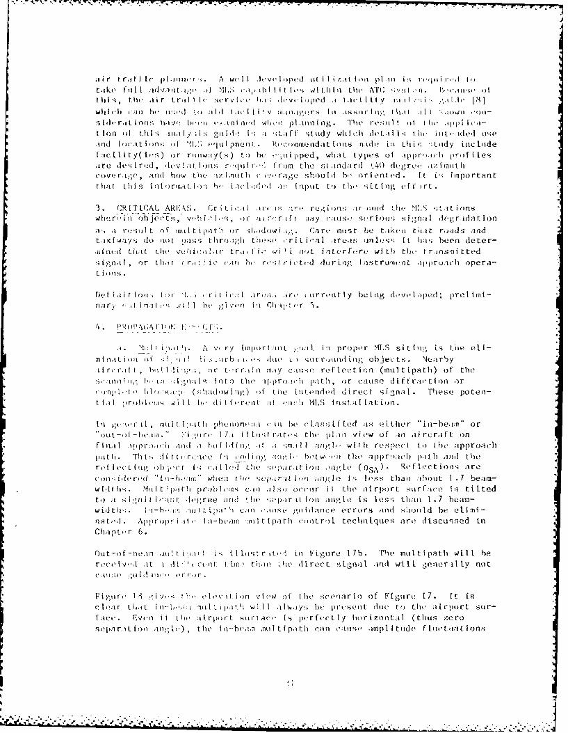
Int gee , mnil 11cut h phc I omeun i c in ft,' c Lass I f led is either i-beavn' oroit-fhii. 1''ori I lI t i losi-t rait. the' plin vie'w of tin ai rcraft on
f imi noipprauiih mnd aI !Pi lid im, -it .m s;n.il I ani' wit t respect to the approaich),It I I. 'This A i r trCIceQ I Colt o !ii , lo ho tw ''ii thte app)roich pa.th ;III, ttileret ledL iog oh irec ti Is ;it led the 'o'ipartt in uin' ( OSA~ R('t lect innsl- areCon,; fin-red "' i-b " when tI?( h cp seprat i,,1 ,ojgJ Is loss05 than ;)but 1.7 beam-wI,1this. Muiltiptti prutblcm.1s clOi its-, occiir it the airpnort, stirfore is tiltedto ;I ,,i , n itI ira t-m dtegree arid ! it, ;epar mllo t Ion;g I ( is less thtan 1.-7 beam-widtth-; . I-b,,mr )"Iml I- i pa~ t 1 con inegiidatice errors and s'u oumid be elimi-na tod . Appropr ioh' ini-beamn l i ipath contro)l techniques are discussed inlChaptur 6.
Out-of-nex-. imit Lip'iO 1i s 111list riteSI inl Figuire 17b. The multipath will berece iv viat I dit ' & (4< O t tiflt thii iTAe i~rect s ignal aind will gene ru lynoc' iou'o .oii i it I or ru r.
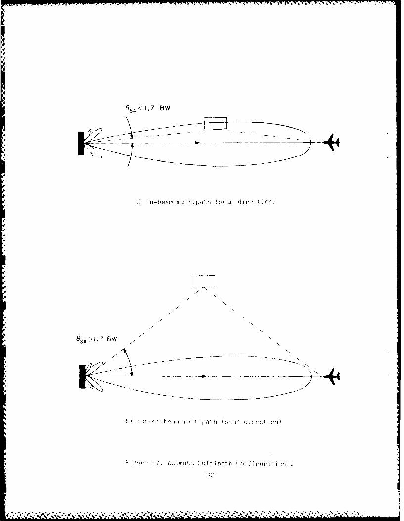
F igir' I iv, 1iivI'sv L Ie ith v ie(w o It le srcenario 1 of Figure 17 . it iscloar thattt nI'm, mt pitt wi I I ;il'w;iys be presenlt dule to thle airport stir-face . Even i f t~o it i[rpo rt sort Aiu'n i s perfecL Iy hor i7onta I ( thus ze rosop.1 ri it Lou n 8 ' the I ii--b(';fno muItL I pathi -;in c('mue ainipti ilode F 1-it('t L ions
- - - - ------------------. -. S ---------------
J.1
4
&SA<I7 SW
* -- -~--
i I in-beam mul t path ( ~r an d i r~r Li or)
.1
* 411N'
7 'N'
7
77
* FiW N N
7N'
7 ~---- - N'
path (sc in direction)
* 17'. Al', i rr~~ith tWi It p aLP ( crif' i gijrat i or
'.3-
**5
-. r*' ~ **~* * -~- S *h*
5-
4-
/l 0
L- 5
. . . . . . -:. . . . . . . . .i.. . . . . . .
which could cause problems in achieving low angle coverage. To mininlzethis nonscan direction nultipath, the azimuth antenna pattern is designedto have a very sh. rp ctitoff near the horizon.
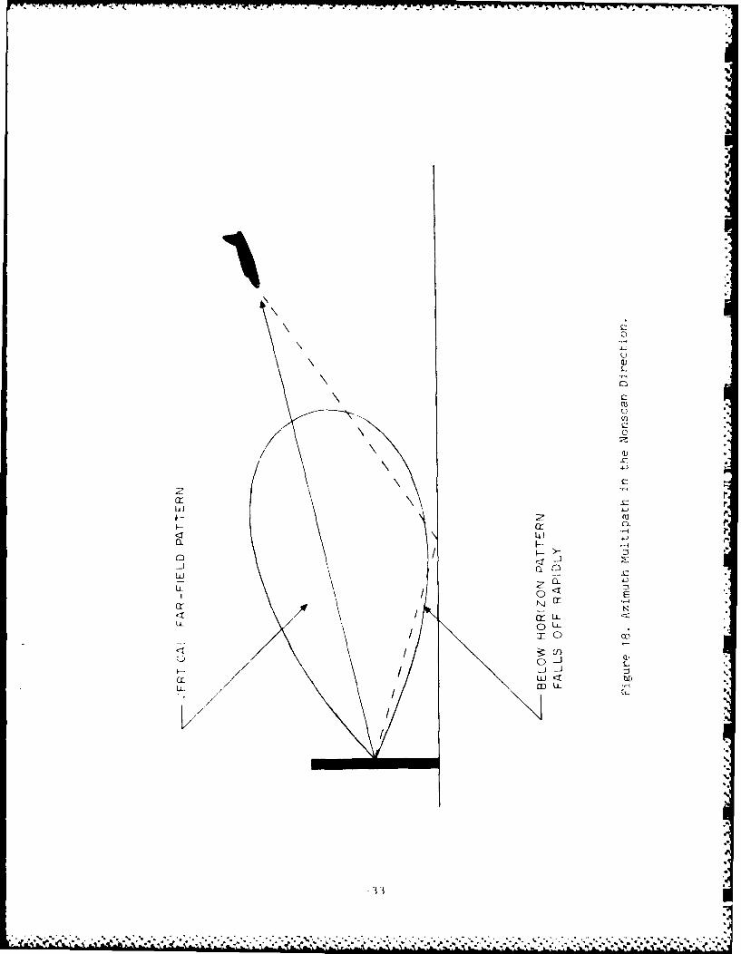
Theso nultipath principles also apply for elovation guidaincc. Igi rI i9;1itI uSLIit es t I i va vLI on scami bI g beam I n the pre soene oI .1 1i 1 i 1i rport,surface. Rising torrain In the approach region, as shown in Fi.*irv 19h,
can reduce the separation angle to les: than 1.7 beamwidths (I -bean muli I-
path) and it-iuse elevation guidance error.
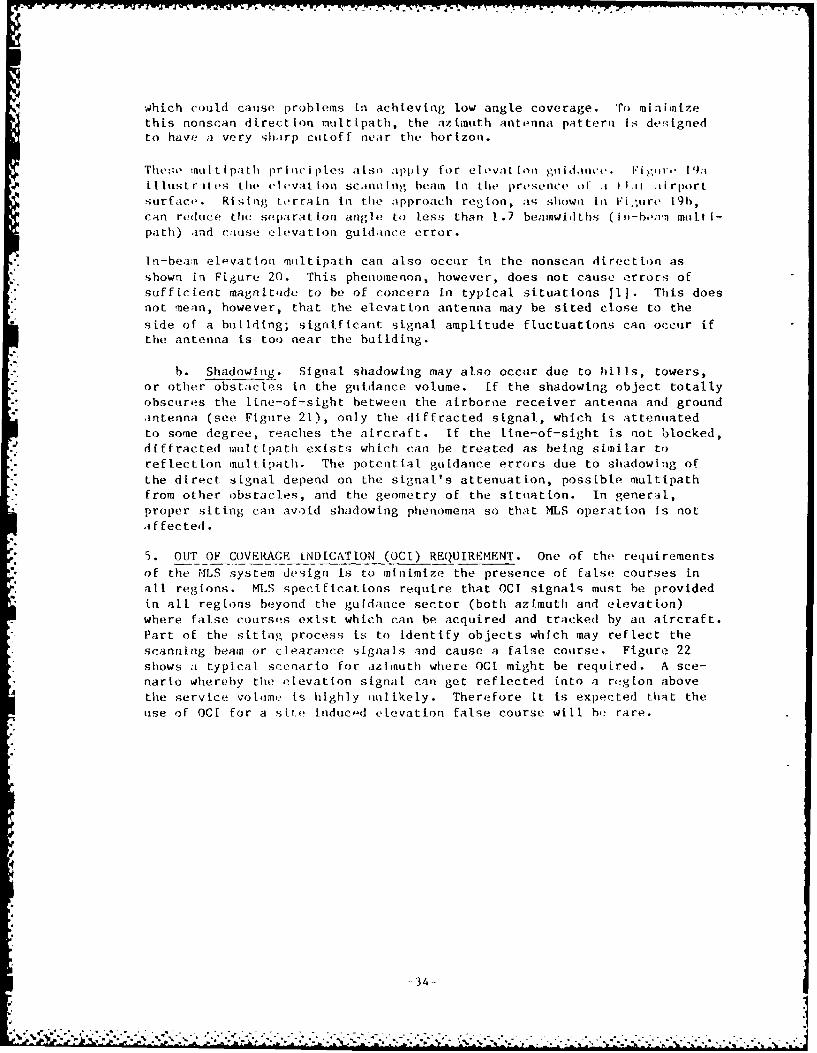
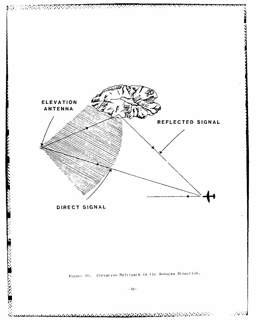
In-bean elevation muiltipath can also occur in the nonscan direction as
shown in Figure 20. This phenomenon, however, does not cause errors of
sufficient magnitude to be of concern in typical situations [I. This does
not nean, however, that the elevation antenna may be sited close to the
side of a building; significant signal amplitude fluctuations can occur if
the antenna is too near the building.
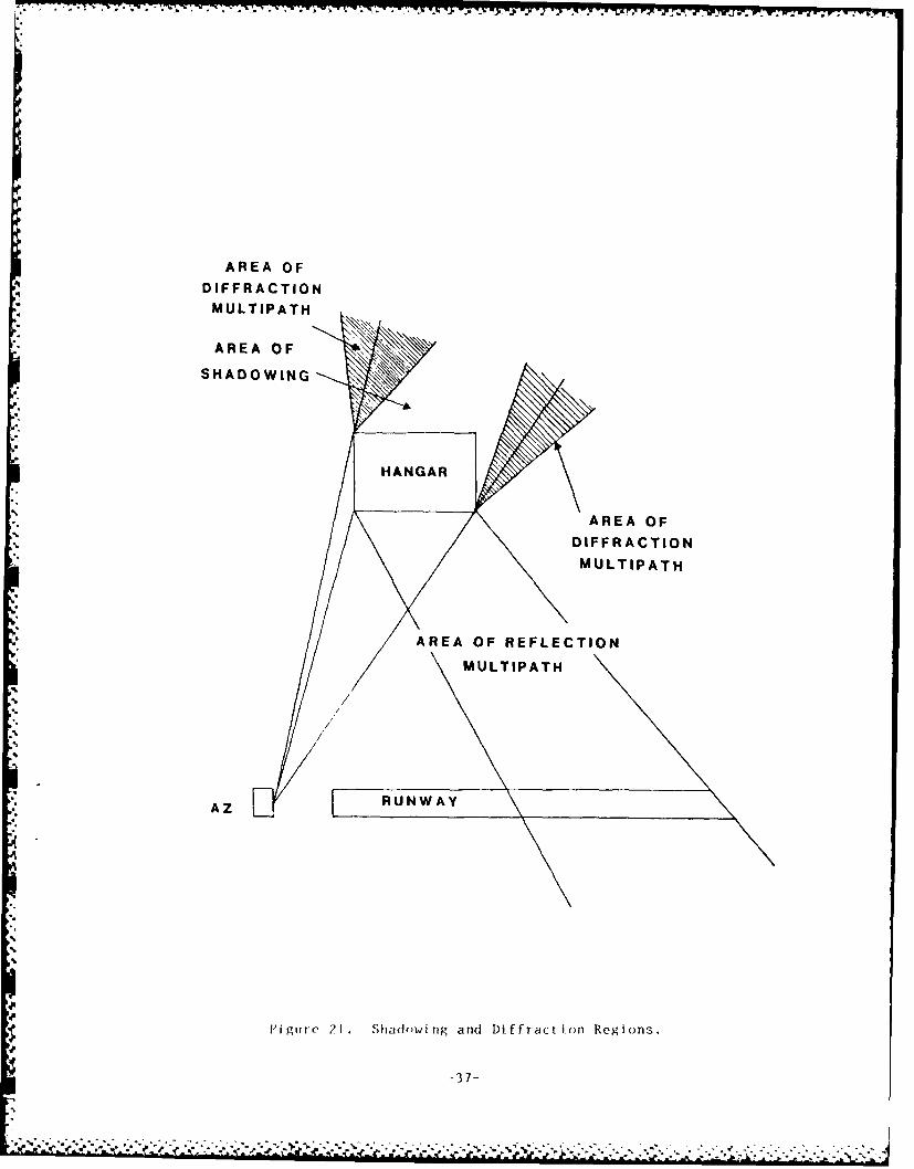
b. Shadowing. Signal shadowing may also occur due to hills, towers,
or other obstacles in the guidance volume. If the shadowing object totally
obscures the line-of-sight between the airborne receiver antenna and ground
antenna (see Figure 21), only the diffracted signal, which is attenuated
to some degree, reaches the aircraft. If the line-of-sight is not blocked,diffracted multtpath exists which can be treated as being similar to
reflection ,nult.ipath. The potential guidance errors due to shadowing of
the direct signal depend on the signal's attenuation, possible multtpath
from other obstacles, and the geometry of the situation. In general,
proper siting can avoid shadowing phenomena so that MLS operation is not
a ffected.
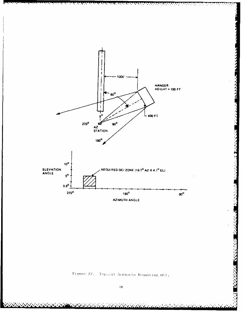
5. OUT OF COVERAGE iNDICATION (OCI) REQUIREMENT. One of the requirements
of the MLS system design is to minimize the presence of false courses in
all regions. MLS specifications require that OCI signals must be provided
in all regions beyond the guidance sector (both azimuth and elevation)
where false courses exist which can be acquired and tracked by an aircraft.
Part of the siting process is to identify objects which may reflect the
scanning beam or clearance signals and cause a false course. Figure 22
shows a typical scenario for azlInuth where OCt might be required. A sce-
nario whereby the elevation signal can get reflected into a region above
the service volitme Is highly ilikely. Therefore it is expected that the
use of OCt for a site inducd elevation false course will he rare.
- 4
.34-
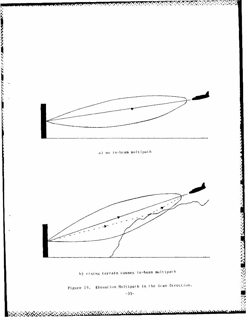
a) no in-beam multipath
h) rising terrain causes in-beam multipath
Figure 19. Elevation Multipath in the Scan Direction.
-35-U
................... ..
DEFRECTE SIGNAL
H oe20). I.'1evat i Oi MUIL U atth in thle Nonscan mriction.
36-
AREA OFDIFFRACTIONMULTIPATH
AREA OF
SHADOWING
HAGA
AREA OF
DIFFRACTION
M ULT IPAT H
AZ RUNWAY
$ Figure 21. Shtadowing and Diffraction Regions.
-37-
1000
ANGLEG50
0.90
270 0 180 90
AZIMUT ANGL
0.90
270 IS 90-. .. .
CIIAPTI:IR sI F IN(; UNI)IiR IDEAL CON[) i iON
1. OV *R V I E' W . One- of L he many ad van tageIfs or MLS i- i t s i nlifr .it r-;LsLtrcto iultipath problemsr. This has been verified hy numerous ;i:i.1lict 'itdies, computefr shwiil at ions, fl ight te-t Ing, and practical pr .
Evans et .a . , in a stLudy of eleven major U.S. and Foreign airp~orts5, fouLi
that ove r ')()Y of runway ends were free of hui [di ngs whii ch coulId prod tics ign if icant ax inn li nuiit ipatli when on finalI approach andI 884 w-r.- free ofbuildings which would produce sign iif ivant elevation inilt ipath 191.
This chapter describes the procedures for locating the az imutLh and eleva-tion anitennas for the simplest siting situation: a flat airport surfacewith no hills, buildings, or other obstacles within the guidance voltime,and no TLS or approach light system present. Although this is not itypi-
cal situation, more complex siting problems genierally involvi! a relIativelysimple correction or alteration of the criteria presenited in this chapter.In Chapter 6, these more complex situations will be disrussti'I along with anntroduhct ion to ap~plications of the ?4LS computer mnodel.
2. A/.PJTH SITK.
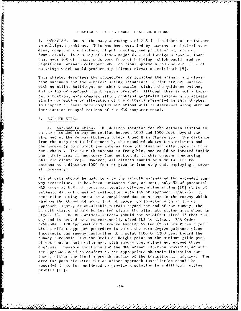
a. Antenna Lo cation. The desired location for the azimutth stat ion ison the extended runway centerline between 1000 and 1500 feet beyond thestop end of the runway (between points A and B in Figure 23). The distancefrom the stop end is inC iuenced by the standard obstruction criteria andthe necessity to protect the antenna from jet blast and oily deposits fromthe exhaust. The azimuth antenina is frangible, and could be locatedA insidethe safety area if necessary (see section d. in this chapter concerningobstaicbo clearance) . However, al L ef forts should be madec to siLte theantenna at a distanice 1000 feet or greater from stop end, employing at towerif necessary.
All efforts should be made to site the azimuth anttenna on the extended runi-way centerli-ne. It has been estimated that, at most, only 5%Z of potentialIlLS sites at U.S. airports nay require off-centerline siting 110] (This 5%estimate did not consider col tocat ion with ILS or approach lights.). Ifrent orli ne sit ivi) cannot Ihe accomnpi Iied due to a hump in the runway whichshadows the threshlold( areai, lack of space, collocation with an I ,S or;tpproach lighits, or unisul table terrain beyond the end of the runway, theaz imutLh stat ion shonul d he located within the alternate siting area shown iii
Figure 23. The MLS az imkith antenna should not be offset si-t'2d if that run-wayf end is served by a convenit onal ly sited ILS local izer. FAA Order9260.30A\ - TFR Approval of Mlicrowave Landing System (MLS) describes a per-il tred of fset appro)ach procedure in which the zero degree guidance planefiiterSects the runway cent en me at a point 1100) to) 1200 feet toward therunway threshold I rom the Decilsion light point oni the ml nimui ,,lido pathoffset course angle (a! ignTmen~t with runiway centertlie) not exceed threedogrees. Posbl orat inns for the MLS azlinuth station providing an off-set :ipproaicm need to) conform to the appropriate obstacle limitation Sur-faces, either the final approach surface or the transitional surfaces. Thearea for possible sites for an offset approach installation should herecordod if it is, ronsidlered to provide a solution to a difficult siting
problen li1.1
39-
9REFERRED
-.. .. . -... . ... . . .f E
A~
A
"It.~l
'I
.-
l
-

Az omitIt sit gli I In the I)reselice of an II'S [loc.l I z(r or Ippro,.cli I I .,I sy, A,,,is .11 scusstd in (:lapter 0.
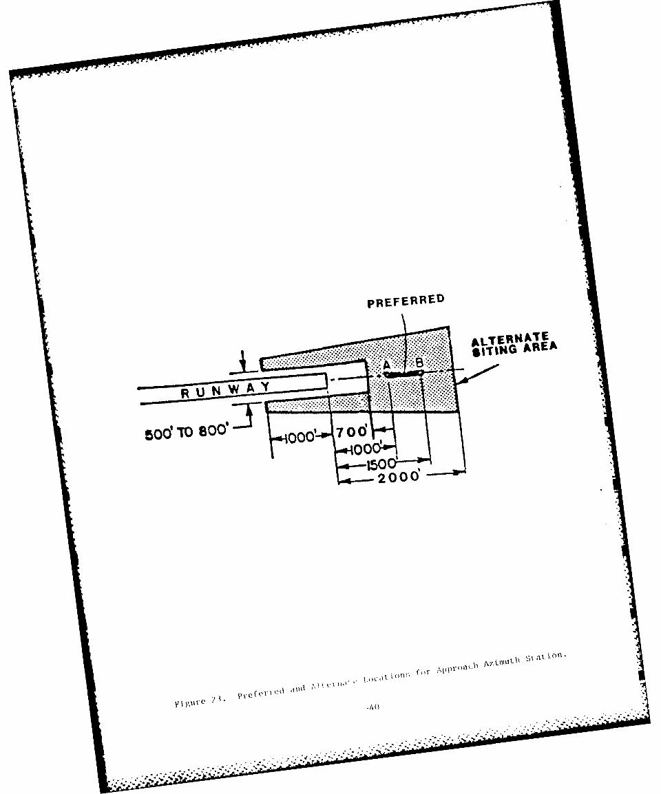
1). Crit i(-; I ArO 4 . Analyl I cal an d ,'Xj)&'r ' I itel o- .1 t ,-I II I'',l 1I),.n l,' tip 00 r1 r'tO'd L do I no the azillnit t ;Im d oLovat ilnl cr Il i,Il ,i',i.i:. TII,Ix zkIit I I ystI ein cr1 { itcal area d pEl(-led in Fig reir ' 24 was devlo- ,I y ;idi
1.1 fiit , I or.-;i caser ion:il ittois on lie IlS conptilor ,no l 12 1 2 . ,'li. wt.ilia,,w.as ;assuimed tin he ;,rounI mounted(-, a111( the airi;rat L intE torer 4 i. I /i/)rionitmd in such a way to give, mnaximum signal. disturbance. o'I orim pos --
tion of the si:nulated aircraft, a cetterl me, 3' approach was i,idelo.1 and
trie ,a/xI[miim valuie of control motion noise (CMN) was recorded (re,;Ir. l!os oftie durat ion of the error). The critical area def tied in Pi,;iic, 24 is are:gion where the scatterer produced a peak C,-IN value equal t) oc grea terthan 50% of the error budget. Other, less conservative, critria are hetig
examined to determine their effect on the size of this critirail area.These :1ew criteria, based on the principle of allowing the path followingerror (PFE) and CMN to be out of tolerance no more than 5% of I specifiedlength of time, will likely result in a smaller critical arn. The lengtlof the criti al area In tie di r tlion of runway threshold is inde fined itI his; t fine.
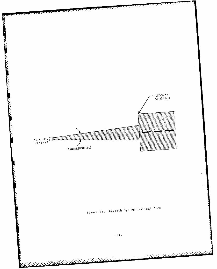
The ozi mth critical area dl itied by the tenth moting of the Al I WeatherOper itiri Paniel (AWOI') ia, sol1' shown to Ftgure 25.
Care iiwo he takei Lo protect the area between the azimuthIl lilt ennla ld it -
fi Ildt inonl t')r.
,. lME P). Tht preferred Iocation for tire DMKE/P is at the azimit Ih
.s;itw(- . yer, this may cts le IME! to violate obstacle c 1eloritice s Ir-face,; (Part 77) if the aziwanli Is site about 1400 feet or less from the!;tol t, of the rtijway . The di sta Lee from the stop end is fwidt by Jetor-mlniig, the necessary antenna he!ight to insure adequate signal it ,roundlevel fri)in Ftgu-r 26 [U1], and checking to see if the 50:I surfact, is'violated for that particular .ntenLa site. If so, the antea. may he mroved
f or ther back (and itq height read justed) until it does not pl ilt'.rat'o tire50:1 ,urface. The DME/P antenna may be also laterally offset in or-ler toavoid penetration of strfaces.
d. Obstar le Clearance. Proper MIS siting is inf luenced by the
necems ity to meet ohstal le i emaraiine requirements. In additioin a thoser quil reentsq iin the' ground plaiie ciui tti ining the runway, thier.' are imagiinarysUr:(es that rise at liflering slopes from different point.s o thile .A!rIrdrome that nay not le porn'tr;ated. For the C;as, of eazAimoth siting, tierolevait surface is the 50:1 ipproach strface. Its inner edge is 1000 feetwide nitid l ies perpendicular to runway cen terlin 200 feet off the ond oftit' runway . It then extends for a horizontal ,distance of 10000 feot at as l)pc of '-():1 and expands uiin-or(nly to a wid th of 16000 feet (see Figure27) l 3.
For an azimutli si.t,! 1000 feet off the runway end, tlhis gives ia al lowabteantenna height of 16 feet. Unless the antenna i - mounted on a t.w)aergreater than 6 feet tall, the 50:1 ;urtace will not be violatu. However,
-41
.; ~ ~ ~~ - . .. ... . . .."- . - --. . . . .- . '-- .4- - .-.. •. .--
f . * -4. . . . .4 . .',.. €.....,.- -,.,........ .",.... _....444-* 4_': ."-
RU.NWA Y
.......... .~* ..
>
S~~~ -- AT
S2 BEAMWIDUlis
Figure 24. Azimuth System CrtCIAre;'.
AN I FNNA '*'\ 'ij'K
I.)~i IN LO\II
N:I FNINN\
byC AWTl CA 1, A RE.
Nf: ~ ~ ~ - ,-RA PIl,.
FIN
RF(1()N IXFDAND OVIN
W L-
0 0
z xZ X
q W
1>0\I Z
2 0
LIc)
* C14 0 Go _ 0 O
.Ld iHDI3H NN31N'V
-/44.-
r. -.. p .... .~.
cr
C) 0)
2000
z 0~j ,
LL 0-0 -0
0 E
C))
7--
a ciji I Icattri DMI/ 1 antenna Ihaving an overal I hIe it l oI f ib it 2Z f 4 t
( Incli (d Ing I ghtn I ng rod) requi res an az Lint II t- ,;.t I .- k o I i 1at 1300feet. IHenct-, It may be desirable to sfte te DMEI,/' spir it. from th. azi-
muth lntenna to opt liize azimuth siting. Wlhisi s01 Inty !;.'pr it ly , it .nay beposs I h le to Iower the DME/ P antenna to cl I r II it- ;l pi tch i r I , ,,.
In gentral, obsLruction standards specified in FAR PArl 77, Siibp.irt C shillbe used to determine required obstruction clearance Iurftcc.. If it i.feasible to install an KILS azimuth antenna withbout penetrating an FAR Part77 surface, do so. However, if the only feasible siting involves
penetrating an FAR Part 77 surface, that siting does not require a waiverbut does require airspace review and approval. In any case, siting an MLS
component must not violate required obstruction clearance as specified inthe latest edition of Handbook 8260.3, United States Standards for Terminal
Instrument Procedures (TERPS).
3. ELEVATION SiE.
a. Antenna Location. The elevation antenna is nominally located 255feet from runway centerline, on either side of the runway. To choose theproper side of the runway to site the antenna, the siting engineer nustconsider the space available, the presence of active taxiways, and poten-tial signal multipath and shadowing problems. The antenna phase centershould he higher than the elevation of the runway, and the bottom of theantenna aperture should be higher than three feet above ground level toprovide snow clearance.
The MLS approach reference datum is a point at a specified height locatedvertically above the intersection of the runway centerline and the
threshold. The minimum glide path angle and the height of the approachreference datum will be determined by FAA Regional Flight StandardsPersonnel prior to siting the ground equipment. FAA Order 8260.34
(Glideslope Threshold Crossing Height Requirements) governs the selectionof the height of the approach reference datum. Factors that will be con-sidered in determining these two siting variables are: type of operations
(analogous to ILS Category 1, Ii, or Ill), categories of aircraft utilizingthe runw.iy and their desired wheel crossing height, and length of runway.
The 14LS ,telvation antenna provides conical coordinates and, thus, MLS glidepaths are hyperbolas ratLher than straight lines. The elevation antennashould be sited so that the asymptote of the minimum glide path crosses thethru.shold at the 1LS approach reference datum. There is a difference inheight between the planar glide path (asymptote to mintmium glide path) andhyperbolic glide paths at threshold; operationally it is desirable to mini-
mize this difference. Figure 28 plots the hyperbolic glide paths for anelevation antenna sited to provide a 3' planar glide path for variousantenna offsets. Thus, minimizing this difference is accomplished bysit ing the antenna as ,lose to the runway centerline as possible. The
relattvoly short height of the MILS elevation antenna will allow siting theantenna 255 feet fron runway centerline ('offset' equals 255 feet).
Once the minimum glide path angle and the height of the approach reference
datum are established, the location of the antenna may be determined in the
-46-
C!)
I- ~ 0
4-
41
ool
E4
Co t
0 o-j
-4
1 4
0D U U)~-
4 U)
ob
0) ~
00
0
-47- 7r
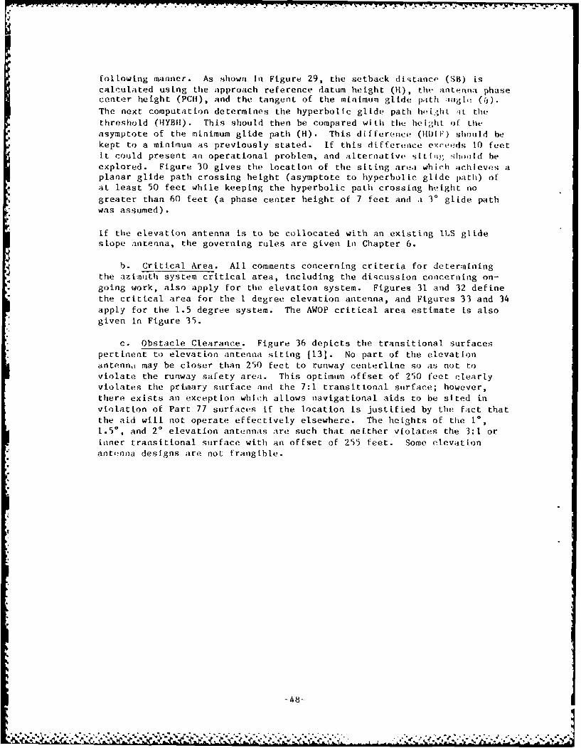
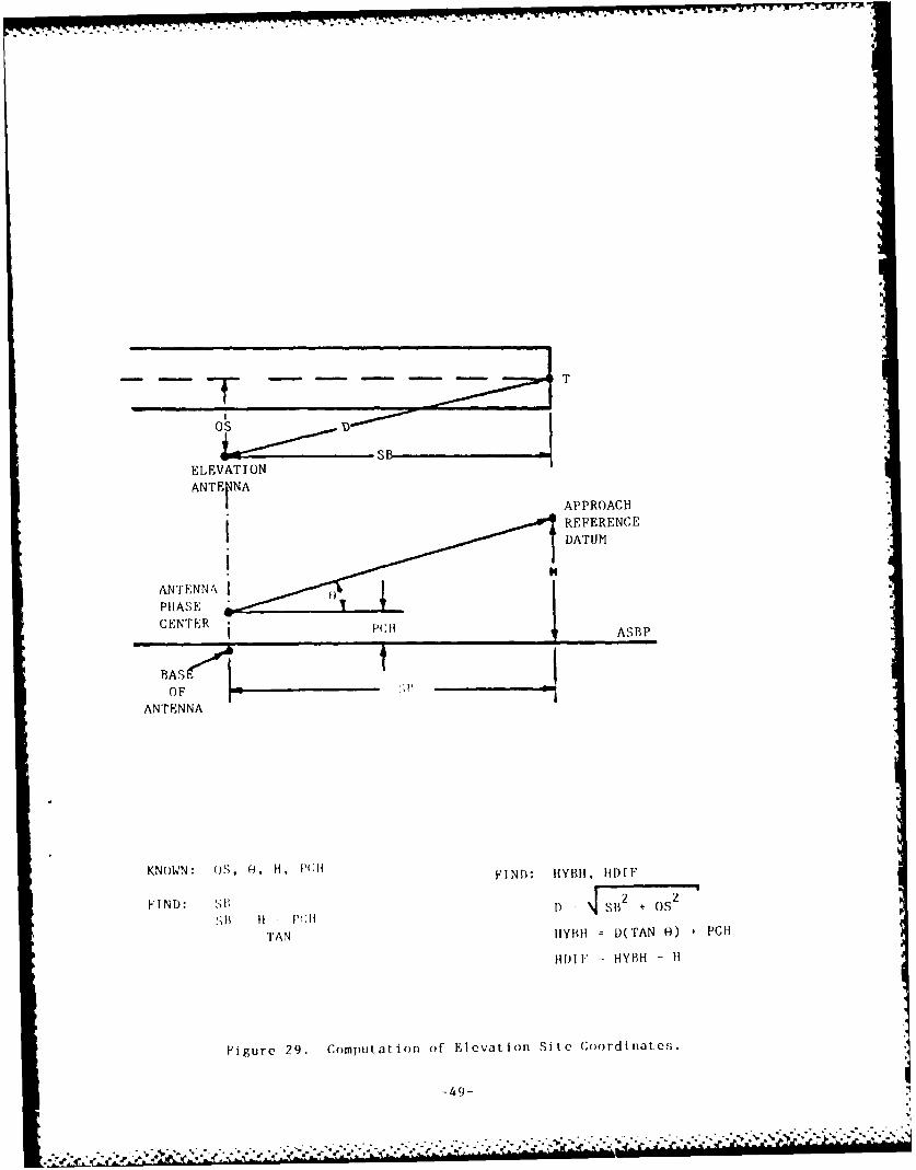
following manner. As shown in Figure 29, the setback distance (SB) iscalculated using the approach reference datum height (H), the antenna phasecenter height (PCH), and the tangent of the minimum glide path a;igl, (,).
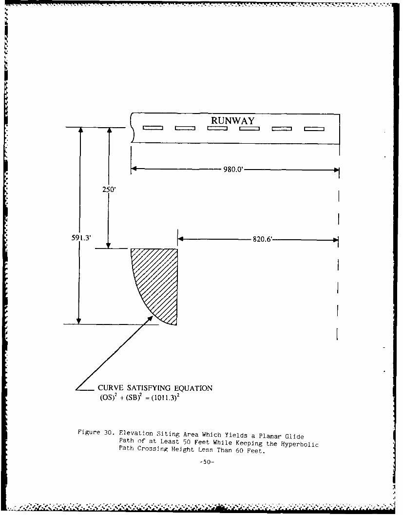
The next computation determines the hyperbolic glide path hti.ghi :it thethreshold (HYBHF). This should then be compared with the helight of theasymptote of the minimum glide path (H). This difference (1i1[F) should bekept to a minimum as previously stated. If this difference excet'ds 10 feetit could present an operational problem, and alternative sitig,' S hlid heexplored. Figure 30 gives the location of the siting area which achleves aplanar glide path crossing height (asymptote to hyperbolic glide path) ofat least 50 feet while keeping the hyperbolic path crossing htight no
greater than 60 feet (a phase center height of 7 feet and a 3' glide pathwas assumed).
If the elevation antenna is to be collocated with an existing I1S glideslope antenna, the governing rules are given in Chapter 6.
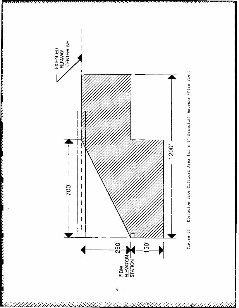
b. Critical Area. All comments concerning criteria for determiningthe azimuth system critical area, including the discussion concerning on-going work, also apply for the elevation system. Figures 31 and 32 definethe critical area for the I degree elevation antenna, and Figures 33 and 34apply for the 1.5 degree system. The AWOP critical area estimate is also
given in Figure 35.
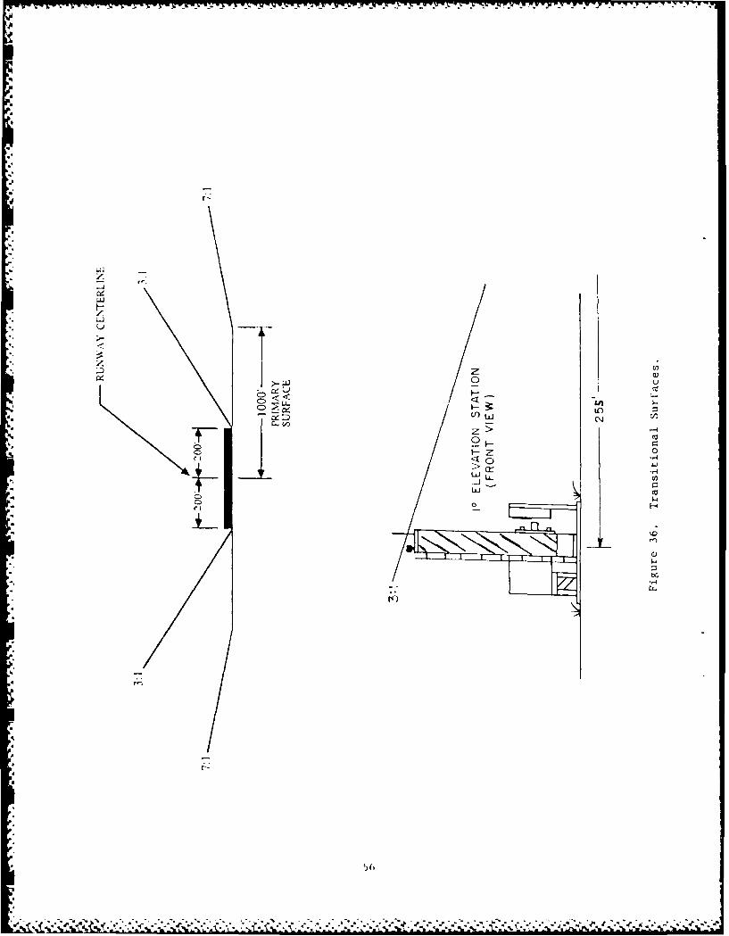
c. Obstacle Clearance. Figure 36 depicts the transitional surfaces
pertinent to elevation antenna siting [13]. No part of the elevationantenna may be closer than 250 feet to runway centerline so as not toviolate the runway safety area. This optimum offset of 250 feet clearlyviolates the primary surface and the 7:1 transitional surface; however,there exists an exception which allows navigational aids to be sited inviolation of Part 77 surfaces if the location is justified by the fact thatthe aid will not operate effectively elsewhere. The heights of the 10,1.50, and 20 elevation antennas are such that neither violates the 3:1 orinner transitional surface with an offset of 255 feet. Some elevationantenna designs are not frangible.
-48-* ** - . . . .• -'- -.- " -l " ..' ,. - . ,, ,l.' ,-,,.,',r .r-,' ..'.-.* ' ",," " , ' ' " ". '"'"'" .;'".-,"
ELEVATION
ANTE~NAAPPROACH
REFERENCEDATUM
PHASECENTER ASBP
BASOF
ANTENNA
KNOWN: OS, 0-, H. PCHI~1m YIHI
FIND:D: HI) 2 7 F
TAN HYBII I)(TAN f0) PCH
HDh F =HYBH - Ii
Figure 29. Computation of Elevation Site Coordinates.
-49-
980.0'
250'I
591.3' 820.6
ZCURVE SATISFYING EQUATION(OS)' 4 (SB) = (1011.3)'
Figure 30. Elevation siting Area Which Yields a Planar GlidePath of at Least 50 Feet While Keeping the HyperbolicPath Crossing Height Less Than 60 Feet.
-50-
jhg 7e
LUIz
Co
Q)4
4j)
51-H
1.44
- - - - - - - - --
-~ -----------
- ~~ -- - - - - - - -- - - -
.~~~~~~~~~ ~ ~ ~ ~ ~ ---.-----.-.-----
......~~~~. .. . .. . . .. . . .. . .
. ~ ~ ~ ~~ . . . . . . . .. . . = .(-- - - - - -
- - - - -- ---------------- ----- ----
- ............ -. ---------- )----
-----------------------------
11....1.11.1...
bb
m LU ul=<.U
k,
C))
CD:
coo
t.0 C0
4
-4
IA -.
- ~ ~~ -- - -- - -- -
- ~ ~ ~~~ - - - - - - - -- - - - -
- -- - - - - - --- - - -- - - -
--- --- --- CD
--- - -- - w ,C- - -- -- - - --- -- --- --- -- - - - - - -- - - - - - -
-- ------ ---- --- ---- - ---- --- ----
- -- - - - - - - - - ---- -
- - - - - - - - - -
-- -- -- -- -- -- -- -- - b. , - --- ---- ---o - --- ---- --- --- - 0... .... .....................
- - - - - - --- - - - - - - -- -- -
-------------~~~ ... kw---------.......................... .. ------------------ *---------------------- f01..... . . . . .. . . . . .. . . . .
-~~~ ~ ~ ~ -- - ---- ------
-C 1
-*1 4b)
-54-
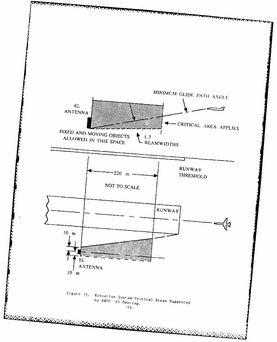
MINIMUM GLID1F PAT11A.\G
EL
"*-CRITICAL /\RE~A APPLIES
FIXED AND MOVING OBJECTS 17ALLOWED IN TUIlS SPACE 13 EAMWIDTHS
RUN WAY220 mTHRESHOLD
NOT To SCALE
~ig r~~ 5* E~ w~t 0 ~ Crf ic l RUNA Yu g s~
10stM
bY At4OP -10 feeting.
.. ~ A -*~-'~ ~ K~ dV *--' \ \. &
CD <.44
Z 04
0
> c,*
* C
9 r,
'I-I
< > 0
LLL,4
a-4
7-4
D c)
crE
a)
* w a)
0
57-O
CliAPTER 6 SPECIFIC SiTING CONCERNS
I. OVERVIEW. This chapter discusses methods of analysis and tiechniqiies to
deal with nultipath and shadowing problems, as well as criteria for collo-cation with ILS and approach light lanes. Where situations thail ;re beyondthe scope of this discussion are encountered, it is recommended that the
MLS Program Office, APM-410, be consulted.
2. AZIMUTH STATION.
a. Multipath. Any objects in line-of-sight of the azimuth antenna andwithin the guidance region are potential multipath sources. Since thewavelength at the MLS frequency is about 2 inches, almost any concrete ormetal surface will reflect, diffract, or shadow the MLS scanning beam.Smaller reflecting objects can cause narrow bursts of multipath as thereceiver moves through the approach zone, but since the receiver isdesigned with :icquisition and validation circuits to acquire the strongestand most persistent signal, the MLS will resist these bursts of short dura-tion [IL].
The real nultipath threat is from large buildings (such as hangars, controltowers, etc.) and hillsides. These large obstacles can reflect thescanning beam over a wide volume. However, the potential for guidanceerror exists only when the approach path passes through the multipath-affected region of space and the "separation angle" between the approachpath and the reflecting surface is 1.7 beamwidths or less. This'separation angle" is the coding angle between the direct approach path andthe obstacle as viewed in the plane perpendicular to the plane of thescanning beam. When this criterion is satisfied, the magnitude of guidanceerror is still a function of several factors, including the reflecting pro-perties of the offending surface.
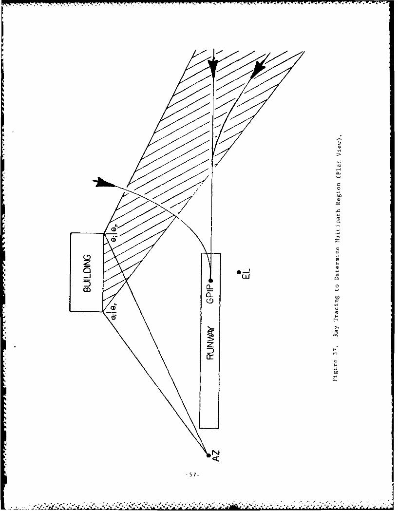
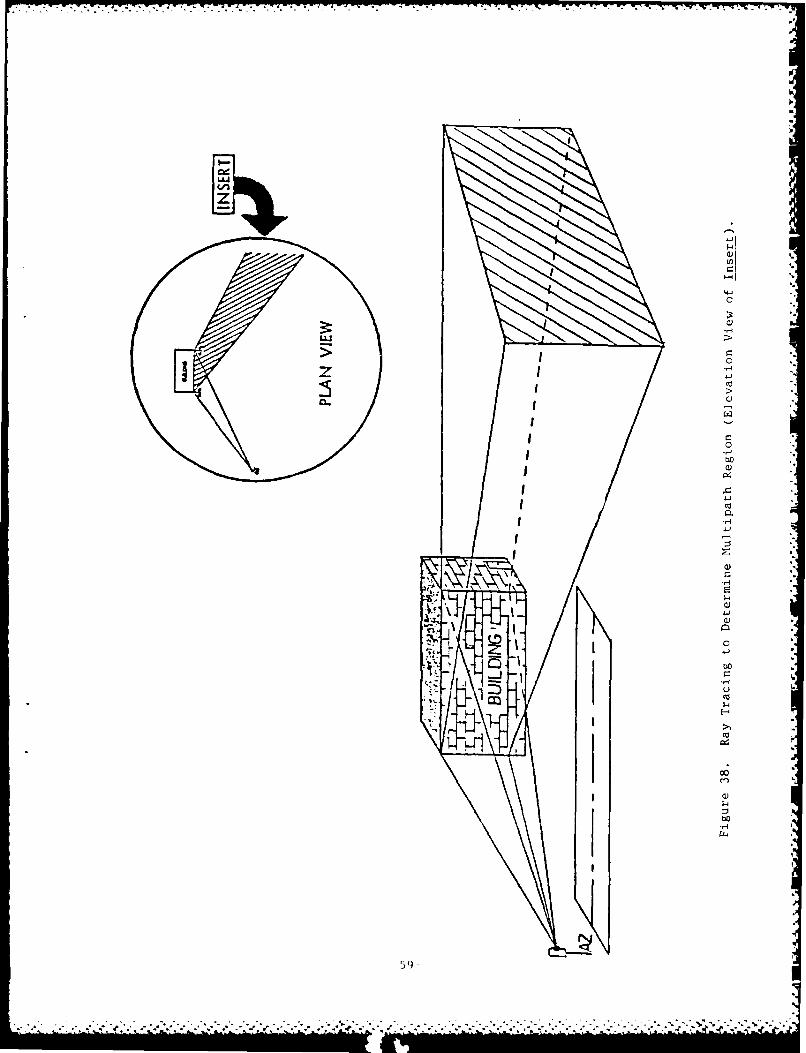
The bounds of the multipath-affected region of space may be determined byray tracing. Figure 37 shows the plan view of a building which is actingas a reflector for the azimuth scanning beam. A "ray" is drawn from theazimuth antenna phase center to the extremities of the object; in thiscase, the corners of the building. The rays form an angle (0i ) withrespect to a perpendicular to the surface at that point. Then thereflected ray is drawn such that the angle between the reflected ray andthe perpendicular (Or) is equal to O. This yields the region of space inthe plane parallel to the airport surface that contains the multipathdisturbance. The vertical bounds of this region may be found by repeatingthis process for the elevation view (Figure 38).
Hence, for a given approach path, multipath-induced guidance error ispossible if the path traverses this region and, at the same time, theseparation angle is 1.7 beamwidths or less. It should be noted that adiffracted signal will exist on either side of the bounds of this region.
To give the siting engineer a quantitative feel for the type of situationthat warrants concern about multipath, computations were performed usingthe MLS computer model. A perfectly reflecting building face of dimensions
-58
T0I-%-w .W
44
bo
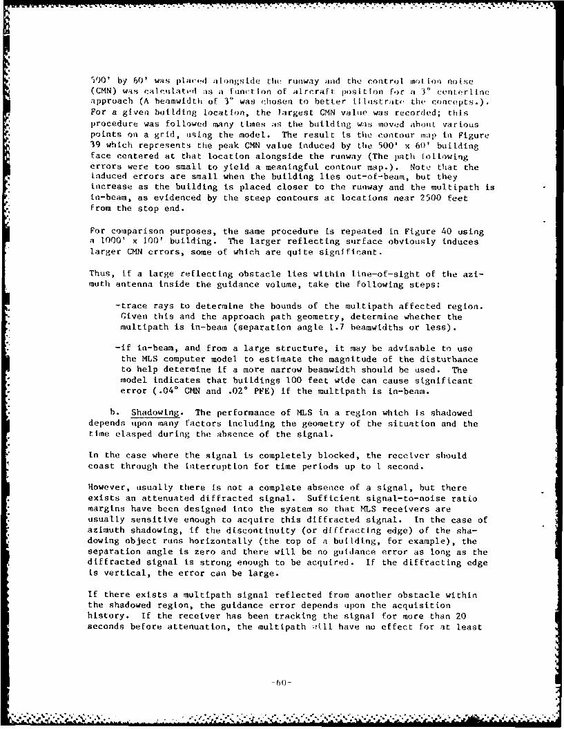
))0' by 60' was pla('f d :alongsIde the runway and the control in[on noise(CMN) was calI.ulated as a func L Ion of a Ircraf t: posIt ion For a 30 center I Ineapproach (A beamwidth of 3' was chosen to better ilhi strate the concepts.).For a given building location, the largest CMN value was recorded; thisprocedure was followed many times as the building was moved about variouspoints on a grid, using the model. The result is the contour map ti Figure39 which represents the peak CMN value induced by the 500' x 60' buildingface centered at that location alongside the runway (The path foLlowingerrors were too small to yield a meaningful contour map.). Note that theinduced errors are small when the building lies out-of-beam, but theyincrease as the building is placed closer to the runway and the multipath isin-beam, as evidenced by the steep contours at locations near 2500 feetfrom the stop end.
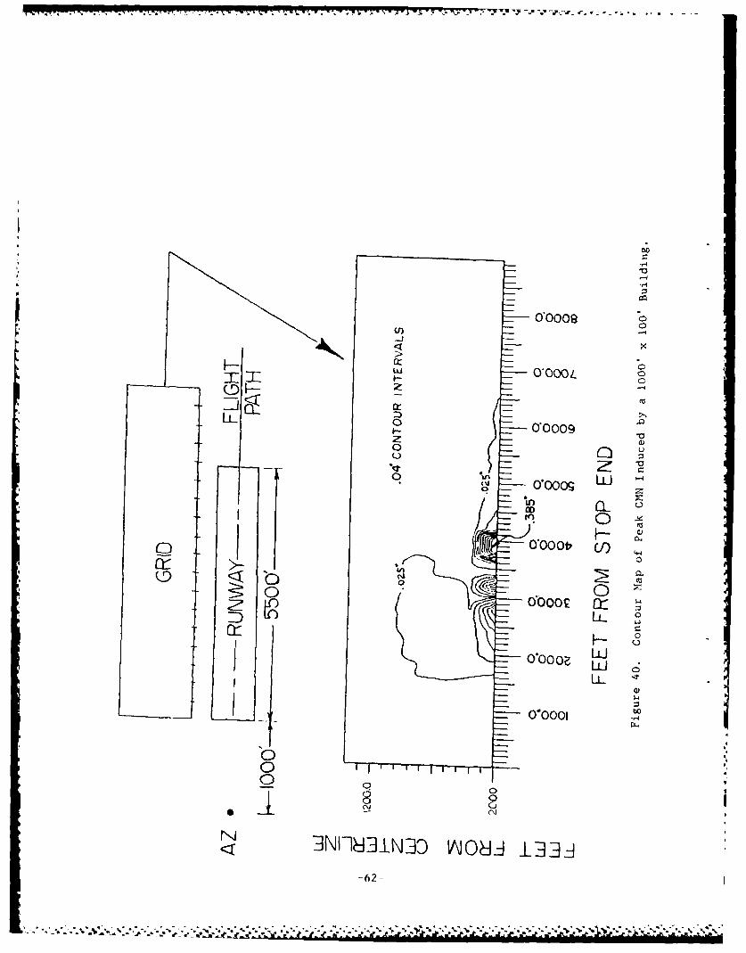
For comparison purposes, the same procedure Is repeated in Figure 40 usinga 1000' x 100' building. The larger reflecting surface obviously induceslarger CMN errors, some of which are quite significant.
Thus, if a large reflecting obstacle lies within line-of-sight of the azi-muth antenna inside the guidance volume, take the following steps:
-trace rays to determine the bounds of the multipath affected region.Given this and the approach path geometry, determine whether themultipath is in-beam (separation angle 1.7 beamwidths or less).
-if in-beam, and from a large structure, it may be advisable to usethe MLS computer model to estimate the magnitude of the disturbanceto help determine if a more narrow beamwidth should be used. Themodel indicates that buildings 100 feet wide can cause significanterror (.04* CMN and .020 PFE) if the multipath is in-beam.
b. Shadowing. The performance of MLS in a region which is shadoweddepends upon many factors including the geometry of the situation and thetime clasped during the absence of the signal.
In the case where the signal is completely blocked, the receiver shouldcoast through the interruption for time periods up to 1 second.
However, usually there is not a complete absence of a signal, but thereexists an attenuated diffracted signal. Sufficient signal-to-noise ratiomargins have been designed into the system so that MLS receivers areusually sensitive enough to acquire this diffracted signal. In the case ofazimuth shadowing, if the discontinuity (or diffracting edge) of the sha-dowing object runs horizontalLy (the top of a building, for example), theseparation angle is zero and there will be no guidance error as long as thediffracted signal is strong enough to be acquired. If the diffracting edgeis vertical, the error can be large.
If there exists a multipath signal reflected from another obstacle withinthe shadowed region, the guidance error depends upon the acquisitionhistory. If the receiver has been tracking the signal for more than 20seconds before attenuation, the multipath .,ill have no effect for at least
-60-
20 .- ' ....- %'-. .- ,' ."--".v .".-.-"""" , . .r '' .'..,-: , ,:"! "; -- '
00009
Cl))
LL- 0,0009.-
-JCL00
00000tr L ,
< 0
.4 000021* 21 ) Ito
* LiJLL J
0
0
000010
0 .0'
0 00 0jII18i3 0OJ 0 3
0*0009
XH
liTLLI 0*000L C
ZJj 0.00( cr3
o00
0 /
*r 0
LL 0
cii
j13-4
_ O~OO-62-
M0-20 seconds (1]. If there is no track history, tOf receiver may lock onto the multipath signal and cause large errors. This has heen de monstratedin a situation where the direct signal was shadowed by a grove of trees and
the receiver acquired the multipath signal reflected from a building. Scan
limiting may remedy this situation, or the approach paths can boeestablished above the shadowed region.
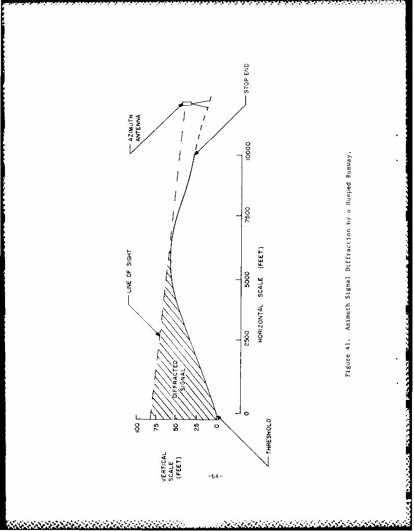
In addition to buildings and terrain, humped runways may cause shadowing,particularly near the critical threshold region. As shown in Figure 41,the hump blocks the line-of-sight between the azimuth phase center and thepoint eight feet above threshold. The signal below line-of-sight is thesignal diffracted over the hump. Although the separation angle is zero,the magnitude of the signal may be reduced significantly. The question ofwhether there is still sufficient signal level for proper receiver opera-
tion is dependent on hump geometry. The MLS computer model may be helpfulin deciding whether a runway hump mandates raising the azimuth antenna.
Hence, is it important to identify regions of space in which the directsignal is shadowed. This is most effectively done using a phototheodoliteplaced at the azimuth site under consideration. A skyline survey should be
taken through 360 degrees to record site details including angle anddistance of skyline and to identify areas in which azimuth coverage may beshadowed. It also allows determination of the size and location of alllarge buildings or terrain features which could be possible causes of azi-muth multipath and/or shadowing [11].
c. Collocation with ILS Localizer. Several studies, both experimentaland theoretical, have been conducted to assess adverse effects of the MLSazimuth antenna on the performance of the ILS localizer, and also effectsof the presence of the localizer on the MLS azimuth signal. The followingare preliminary recommendations.
The characteristics of localizer arrays and knowledge gained from previousexperience indicate that placement of the MLS azimuth station on localizer
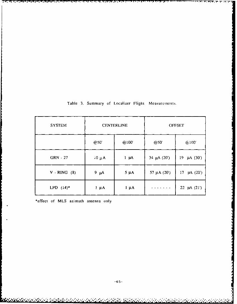
course centerline should produce the least effect on the course. Theregion investigated was from localizer course centerline to an maximumoffset of 500 feet. For an offset of 20 feet, appreciable effects on thelocalizer course were noted; as the offset was farther increased, theeffects on the localizer course were reduced but still considerable. Table
3 summarizes the data collected for the three types of localizers investi-gated. This table is composed of two headings. The data under the cen-terline heading show the effects on the localizer course for the MLSazimuth station mock-up on course centerline for placements of 50 and 100
feet ahead of the localizer array. The offset heading contains the datathat produced the maximum effect on the localizer course for distancesahead of the localizer array 50 and 100 feet. The numbers in parenthesesare the offsets from the localizer course centerline where the MLS mock-up
produced the effect.
The flight measurement data confirm that siting the MLS azimuth station onlocalizer course centerline is the only feasible placement when the azimuthstation is sited ahead of the localizer. The data indicate that for
-63-
a-
Z0
wwza
00-0)
I 0
0-0
C)C
w -
0 0
0 c000 w
00
U, U
LJJ
Lz
W. U. 64> \n
sit,
*~~~ - 'WW 'IT 'Y R 147 -v- 7~ '-
Table 3. Summary of Iocalizer Flight Measurements,
SYSTEM CENTERLINE OFFSET
@50' @100' @50' @ 100'
GRN - 27 A0 piA I pA 34 pA (20') 19 pA (30')
V - RING (8) 9 11A 5 pA 57 gLA (20') 17 pA (20')
LPD (14)* 1 .tA I pA 22 tA (21')
*effect of MLS azimuth antenna only
-65-
localizer arrays similar to the GRN-27 or a 14-element wide aperture logperiodic dipole, siting the MLS azimuth station 100 feet ;he;id of thelocalIzer has negligible effect on the local i ,"r course. F'or th, 8-element
V-ring some effects were notlced .it 00 feet. Therh r,, wheti t,)l;i, 1the
MT.S azimuth statton sholI be sIted at dl-tances ) ,,re.,er Ithn 10) tt lor
these types of local izers.
If the localizer is close to the stop end and iou)int g the aztnitth 1intenna[n front of it would violate obstacle cLearance requirements, or ifproblems with approach light systems require the azlintith antenna to betower mounted, the azimuth antenna may then ho behind the localizer. Inthis case, the azimuth antenna phase center should be at least 3 feethigher than the localizer elements and mounted in the horizontal directionno closer than 10 feet. As shown in Figure 42 [141, as the azLinuth antenna
is moved further back than 10 feet, the phase center should be raised toinsure that the localizer is in the sidelobe region of the azimuith antennavertical-plane radiation pattern.
If the localizer has a backcourse, symmetrical siting of the azimuthantenna is important to minimize disturbance to the backcourse signal.
d. Coexistence with Approach Light System and Other Objects in theNear-Field of the Azimuth Antenna. Small shadowing objects such as poles,
chain link fences, and power lines in the far-field of the MLS antennashave negligible effect on performance [7]. Such objects may introduceerror, however, if they are within the near-field. The distance from theantenna which defines the far-field/near-field boundary is given by
2D2
Distance from antenna =
where D is the longest dimension of the antenna (the diagonal For a rec-tangular aperture, or the length for a line array) and X Ls the wavelength.For example, the far-field boundary is about 421 feet for the 2' azimuth
antenna, and 872 feet for the 1 azimuth antenna.
Experiments have shown that metallic cylinders as thin as 4 inches placed200 feet away oi boresight from the azimuth antenna can cause significant
error [9). All efforts should be made to remove objects from the near-
field, and minimize the width of any that must remain.
If an ffLS is to be sited on the same end of a runway with an approachlighting system (ALS), a potential conflict exists. The azimuth antennamust clear light structures in front of it to insure signal integrity whilenot blockiug any lights and therefore reducing the effectiveness of the
ALS.
The approach light plane is an area containing the lights in a single hori-zontal plane at the elevation of the runway threshold centerline and is 400feet wide centered on the extended runway centerline. It may be horizon-
-66-
. % .-- ~.-.......... .:..,.. .,,.:...-:...-., ,-o,. -.....-. !
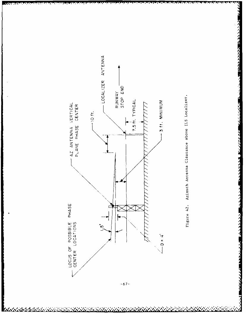
Lii
0 z
LiW 0z
Qua
cLd
w< (r 14)a)
UJU
<j M
ao
w-- t
am0
0 10
Li
-67-
tal, hut a slope gradient riot to exceed two pr(:ent is allowed, starting nocloser than 200 feet from landing threshold. The ILS will istially violatethe approach light plane; a waiver must be obtained if it dloes.
There 1:- also a clear 1ine-of-sight (LOS) requiir,-,,It I I) Ill li ,h ts ,)f thesysten from any point on the surface, one-half dvgr,.e bl),l,)w tlik IS *qLidepath and extending 250 feet each side of the center1hine, up t,) 1i00 feet Iniadvance of the outermost light in the system.
Calculations based on this criterion show that for the ALSF system, the 71/2foot tall azimuth antenna can be sited no closer to stop end than the 1900
foot station to meet this LOS criterion [13]. Hlowever, any site meets theLOS criterion with the MALS system. (This assumes the antenna is mountedon a tower of height equal to that of the light station directly ahead of
it.) The DME/P antenna will violate the LOS requirements if sited behind
and above the azimuth antenna; it may have to be offset and lowered.
3. ELEVArION STATION.
a. Multipath. The concepts presented in Section 2a. for azimuth,ultipath also hold for elevation multipath. Rising and/or discontinuousterrain in the approach region constitutes the largest threat. Since ashift in the elevation antenna location will not usually help in this
situation, the use of a more narrow beamwidth is the more likely solution.Figure 43 gives the formula for calculating the separation angle for areflection from terrain rising at an angle 0 slo e given the glide path
angle (0EL) and the elevation antenna phase cenler height H [l1. If theelevation antenna beamwidth Is less than or equal to this separation angledivided by 1.7, the multipath will be out-of-beam. Since there is always astrong reflection from the flat airport surface, the elevation antennasideLobes are suppressed to a great degree.
b. Shadowing. The comments made in Section 2b. for azimuth signalshadowing also apply for elevation signal shadowing. However, for the ele-vation case, objects whose discontinuities are vertical will not causeguidance error if the diffracted signal is acquired, but horizontal discon-
tinuities may. But, in general, all efforts should be made to site theantenna io that shadows are not introduced into important volumes ofairspace, or avoid approach paths which pass through shadowed areas.
As was the case at the azimuth site, phototheodolite survey measurements
are made from the tentative elevation sites to make terrain profilemeasurements and Identify areas in which elevation coverage may berestricted.
c. Collocation with ILS Glide Slope. When collocated, the elevationantenna shall be sited such tiat the XLS reference datum and the ILSreference datum are coincident within a tolerance of 3 feet. (This assumes
that the ILS glide slope is sited such that the height of the referencedatum meets the requirements of FAA Order 8260.34.) This will place the
elevation antenna about 180 feet closer to threshold than the glide slope
antenna.
A68-
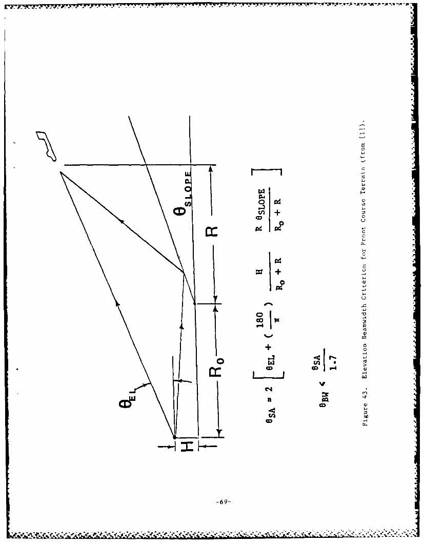
.~j-zw "j r-. . . . . . . . - - - - - - - - -47 -7 77 Y
C
cf+ 0.
0
CDC
-6-4
-,d~i4-)

However, the offset distance from runway centerline is an important Factorin assuring satisfactory glide slope performance in the presenc, of theelevation antenna.
Considering ground plane effects, I.e. Fresnel zone, and kiowid., ,.i ndfrom previous glide slope invest igat ions indicate that the, ofC cts on theglide slope course caused by MLS elevation equipment caii e m mintiized byavoiding siting that penetrates the Fresnel zone. The Fresnel .. iLmigrates on the line between the receiver and the glide slope, -hangiag insize as it migrates. To minimize the effects on the entire glide path theMLS elevation station should be sited so that it lies outside the regionthrough which the Fresnel zone migrates. This indicates that siting theMLS elevation station on the run side of the diagonal between threshold andthe glide slope should produce little effect on the course.
Table 4 contains the flight measurement results for the sideband referenceglide slope. The data collected for this system show it to be the mostsensitive to the MLS elevation equipment. Figure 44 shows the location ofeach position relative to the glide slope. The diagonal between thresholdand the glide slope intersects the I and 1 1/2 degree 1LS elevation rows atoffsets of 332 and 348 feet, respectively. The flight data show that foroffsets greater than 350 feet, the effect on the glide slope structure issevere. Offsets of less than 350 feet produced a lesser effect, exhibitinga minimum as the offset approaches the minimal 255-foot offset. In theevent that the glide slope is offset 250-350 feet, it may be possible tosite the MLS elevation station at an offset 50 to 100 feet greater thanthat of the glide slope. However, at this time there are no data con-firming that this type of siting will produce satisfactory results.
4. DISCUSSION OF COMPUTER MODELING TO AID IN SITING. A computer model ofthe MLS was developed for the FAA by the Lincoln Laboratory of M.I.T. toassess the effects of reflections and shadowing on system performance. Themodel is currently operational at the FAA Technical Center, and at theAvionics Engineering Center at Ohio University.
The MLS model consists of two smaller models: the propagation model andthe system model. The propagation model calculates the reflected and/orshadowed signal at all points along a given flight path. The system modelthen predicts and plots the raw error, path following error, and controlmotion noise as a function of distance along the flight path. All userdefined parameters are read into the model via a FORTRAN BLOCK DATAsubroutine. Graphical displays of airport layout (including placement ofuser-defined objects), and flight profile are included.
If the siting engineer deems It i:ecessary to model an airport scenario, alist of the following information is needed as input to the model:
-the x, y, and z coordinates of the azimuth, elevation, and DMEantennas. The origin is defined to be the intersection ofthe centerline and the stop end of the runway. The x-y planelies on the airport surface, with the positive x-axis lying on thecenterline. The positive z-axis measures altitude and passesthrough the stop end of the runway.
-70-i
*.~ % * . . .. .
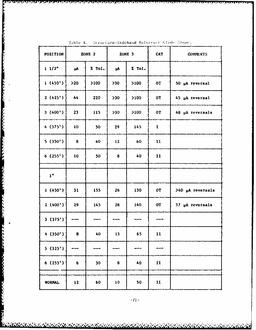
Table 4. :',Iru( urc-Sidebaiid Refor'iu c, (;lid 'l( p,.
POSITION ZONE 2 ZONE 3 CAT COMMENTS
1 1/2° pA Z Tol. I&A Z Tol.
1 (450') >20 >100 >30 >100 OT 50 VA reversal
2 (425') 44 220 >30 >100 OT 45 VA reversal
3 (400') 23 115 >30 >100 OT 48 pA reversals
4 (375') 10 50 29 145 1
5 (350') 8 40 12 60 I1
6 (255') 10 50 8 40 11
1*
1 (450') 31 155 26 130 OT >40 UA reversals
2 (400') 29 145 28 140 OT 37 UA reversals
3 (375') -.-- ---
4 (350') 8 40 13 65 11
5 (325') -- -- -
6 (255') 6 30 8 40 II
NORMAL 12 60 10 50 1I
-71-
*. .)' ' .' '', . . % . ,,, . 4 e. ,, J, ', . V - Z' . .- ,,.-' .,- ,, ,,, . ,/, . . ,. ,- . , xi,,,- . .,-...- & - . - ~. . **. - . - -A,-
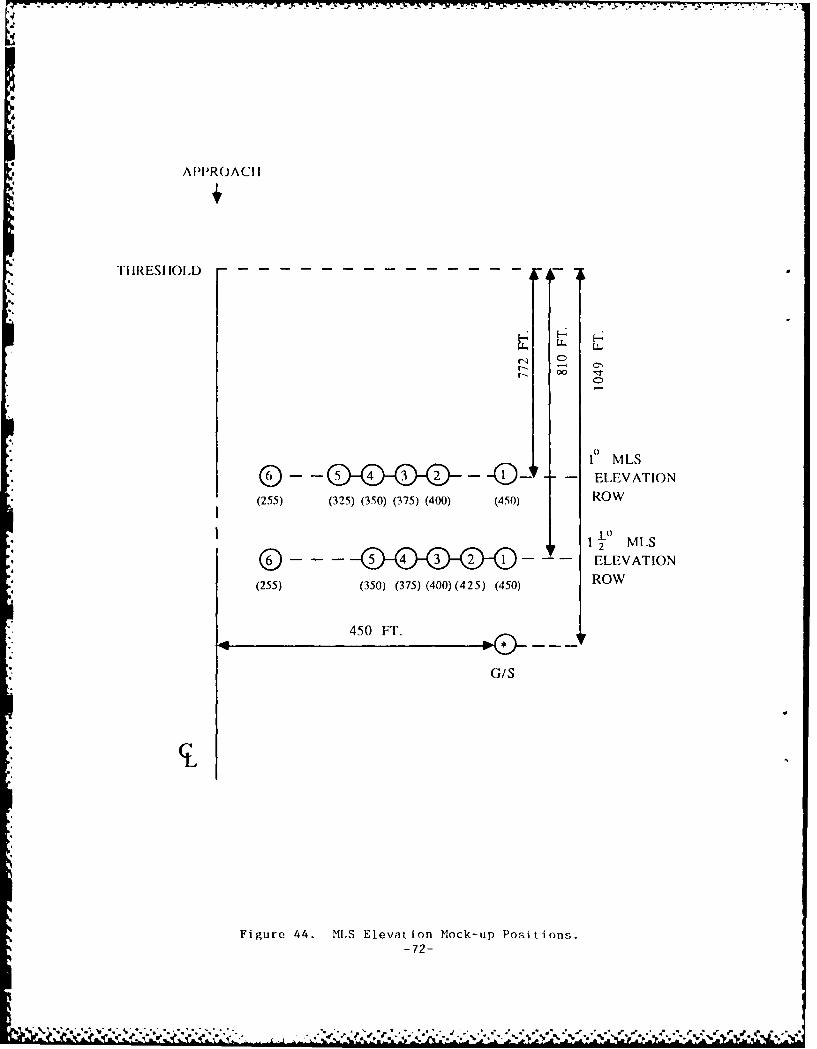
APPROACI I
.TH RESH OL D," --
- I4
'rIR-IO.D--0
10 MLS
0 -D - ELEVATION(255) (325) (350) (375) (400) (450) ROW
10
2 12 MLS
D *ELEVATION
(255) (350) (375) (400)(425) (450) ROW
450 FT.
G/S
Figure 44. MLS Elevati.on Mock-up Positions.-72-

-iti) to ten r'-t.;Ingular and ten triangul .r pl.ales rpresent ing:;J)e('C l ;Ir .rfitiid reflect Ion may be ) 'I I 14d . The I r coord i n;a I ,;RM,; ;ir ic'i. rotl ;ghe!;s hei;ghL, and compljox di o-. l.ric !')ie;t.oiL
a r ' rir .ii rod
-a t(tal of ten plates representing scattering; and shadowitg buildingsurfaces can he specified. When necessary, each bulIdiug (-in lerepresented by more than one plate. For each plate, it is required
to know the coordinates of the corners, the !;urface roughness,complex dielectric constant, and the tilt of the building with
respect to the vertical.
-a total of ten scattering and ten shadowing aircraft can be modeled.Each aircraft is specified by the x and y coordinates of the nose
and tail, type of aircraft (B-747, B-707-320B, B-727, DC-IO, C-124,Convair 880, or Hastings), and the altitude. Other aircraft may be
modeled if necessary.
-the x, y, and z coordinates of the front, center, and back of arunway hump.
-the number of waypoints in the segmented approach, the x, y,and z coordinates of the end points of each segment, and the
velocity of the receiver in ft./sec.
-runway length and width, the coordinates of the glide path
intercept point, and the 3dB beamwidth of the antenna system.
d For further information on MLS modeling, contact Federal Aviation
Administration FAA/APM-400, 800 Independence Ave. S.W., Washington, D.C.
-73-
• ,.., .............-. ,.,..,...,..,".. .
ILl Red I l'n, I1. W. and R. .I. Kelly, *'MI crowivv lin~dllii, ;y,;Lel': Tihe New
[Lhit eriiatL onll ,St;andIrd," e, n i Commtilllt I I i l ; l)ivisior, B;iI I II rio,r
flaryland.
[2] "An Analyst of the Reqti rements for , and ho Bono f I ts ;ind Co';I ofthe National Microwave Landing System (MLS)," rAA-EIM-80-/.
[3] DOT-FAA Specification FAA-STD-022c.
[4] DOT-FAA Specification FAA-E-2721/2b, MLS Ground Equipment, AngleGuidance and Data.
[51 DOT-FAA Specification FAA-E-2721/Ib, MLS Ground Equipment, GeneralRequirements.
[6] DOT-FAA Specification FAA-E-2721/3c, MLS Ground Equipment, PrecisionDistance Measuring Equipment, DME/P.
[7] Radcliff, R. D., "Signal Disturbance Due to Metallic CylindricalConductors at the MLS Frequency," Technical Memorandum M-20, AvionicsEngineering Center, Department of Electrical and ComputerEngineering, Ohio University, Athens, Ohio, August, 1984.
[81 Air Traffic Control Facility Analysis Program for the MicrowaveLanding System, FAA Order 7110.86, November 6, 1985.
[9] Evans, J. E., et. al., "MLS Multipath Studies, Phase 3, Final Report,Vol. 11: Development and Validation of Modeling for MLS Techniques,"Lincoln Laboratory, M.I.T., ATC-88, February 7, 1980.
[101 All Weather Operatiois Panel, Tenth Meeting, Agenda Item 2: MLSTechnical Considerations, "Techniques for Off-Centerline AzimuthSiting," presented by S. Everett, Montreal, Sept. 4-21, 1984.
[111 "Microwave Landing System Site Survey and Performance AnalysisHandbook," Report 11708, Hazeltine Corporation, March 27, 1985.
[12] Chamberlin, K. A., "Computer Model Study of MLS Derogation Due toScattering from Aircraft on the Ground," Technical Memorandum M-24,Avionics Engineering Center, Department of Electrical and ComputerEngineering, Ohio University, Athens, Ohio, July, 1985.
[13] "MLS Obstacle Area Siting Considerations," MSI Services, Inc.,Technical Memorandum, July, 1985.
[14] "Microwave Landing System Ground Equipment Des.gn Study for ILS/MLSCollocation," Hazeltine Corporation, Report 11749, July 2, 1985.
-74-
% 4° - " % ". ". -- "' "- "" -" " "" " " "" -- ~.................................................... ""-"4""" " " . ...-..... . . ." ."..".. "...

PE