Embed Size (px)
Citation preview
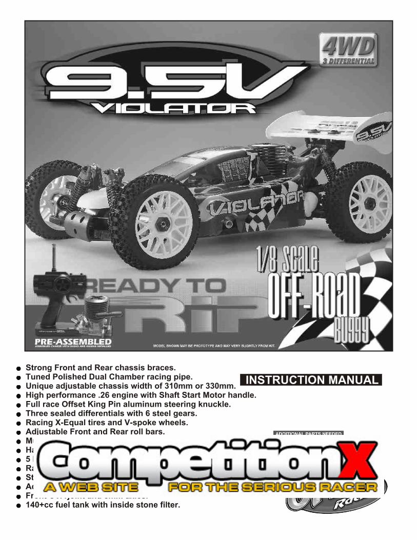
INSTRUCTION MANUALStrong Front and Rear chassis braces.Tuned Polished Dual Chamber racing pipe.Unique adjustable chassis width of 310mm or 330mm.High performance .26 engine with Shaft Start Motor handle.Full race Offset King Pin aluminum steering knuckle.Three sealed differentials with 6 steel gears.Racing X-Equal tires and V-spoke wheels.Adjustable Front and Rear roll bars.Multi disc brakes with adjustable bias.Hard Coated Threaded body oil fill shocks.5 Degree hard coated 3mm chassis.Racing 3 shoe clutch with Aluminum CNC flywheel.Steel main spur gear and center differential.Adjustable servo saver.Front CVA joint and 8mm axles.140+cc fuel tank with inside stone filter.

MUST READ THIS BEFORE RUNNING
Running a nitro kit is fun and easy, but to make this a safe • Clean oil and dirt from chassis with a degreaser.
and good experience you must observe a few rules. This Precautions
kit is extremely fast, easily over 40MPH, and can seriously • This kit is not a toy. Always run car with a second
injure someone if you are not careful.person as a spotter and pitman.
Where to run car?• Hot Parts - The pipe, manifold, engine and head are very
• Any running area you choose must be dry. Do not run hot and will cause burns.
car near any water or wet dirt.• Do not run on public streets. It is very easy to have the
• Rotating Parts - Keep hands away from the drive train, car run over or damaged by hitting the curb.
wheels, and engine when engine is running.• Do not operate car in tight confined places. The car is
very fast and will easily hit something. • Radio - Check batteries life before running the car. If • Do not run near people or animals.
radio does not have full control of the car with steering
and/or throttle/brake do not run until corrected. Failure to • Due noise, you will want to consider the surrounding
correct this will result in possible injury and damage to the area when operating the car.
car or property.• Do not operate the car at night. You will not be able to
drive it without hitting something.• Glow fuel - Do leave the glow fuel unattended with the lid
• Do not operate the car indoors. Engine exhaust is not off. Fuel contains Methanol and Nitro Methane and is
healthy.flammable and poisonous.
Glow FuelStore fuel in cool ventilated location. Refer the glow fuel • Glow fuel is poisonous!
• Glow fuel is flammable! label for additional precautions.• Do not leave in fuel bottle with lid off at any time.• Do not use any fuel other than glow fuel in this engine. • Car Fuel tank - Never store fuel in car tank, it will ruin the
engine if left in tank.First Time Starting the EngineCaution! When starting engine make sure the following is • Always turn off the car BEFORE turning off radio.observed.• Set engine Master needle to 3 turns (rich setting) • DAMAGE DUE CAR RUN AWAY IS NOT A WARRANTY • Do not do this alone, get an experienced friend to help at ISSUE.first.• Fill fuel tank, try not to spill fuel. Do not spill fuel on IF YOU DO NOT BREAK-IN ENGINE receiver
CORRECTLY, MAINLY AT LOW RPM, • Hold car off the ground, so it will not runaway when first
starts YOU WILL BREAK THE CONNECTING • Turn on Radio and check the linkage before starting
ROD!engine.• Turn on car receiver battery switch.• Always have an air filter on the carburetor to keep dirt
FAILURE TO NOT READ AND out.
FOLLOW BREAK-IN ENGINE Engine Break-in• See Engine Page.
INSTRUCTIONS WILL VOID Emergency Stopping Engine When Running• Remove air filter and cover carb. intake. WARRANTY!• Squeeze fuel line and hold until engine stops.• With a rag, cover exhaust outlet.
Storing Car After Running• Remove fuel from tank and fuel lines• Turn off radio in car• Put a few drops of after run in engine to keep it from
rusting.
The car is very fast
and will too easily hit someone.
RTR KITS - REQUIRED FOR OPERATION
THINGS NEEDED
AA Batteries ( 12 pcs )
Glow Fuel20%
TOOLS NOT INCLUDED IN KIT,BUT NEEDED TO MAINTAIN YOUR CAR.
Phillips Type Screw Drivers ( L )
Phillips Type Screw Drivers ( S )
Needle Nose Pliers
Cutter
Curved Scissors#91009 $5.95
Knife
Instant Cement
Cross Wrench#17109 $3.95
Glow Plug & 17MM Cross Wrench#10801 $6.95
Grease
You need to get batteries for the radio transmitter and the car receiver packs.• Radio TX needs (8) eight AA batteries.• Car needs (4) four AA Ni-cad batteries 2000Mah OFNA #10196 or (4) Alkaline., Alkaline type batteries will work, but braking will be reduced and 30 minute life. The best for car, is to use a 5 cell hump receiver pack for increased voltage and longer life..
Recommended Option:You may want to upgrade the car battery pack to a Ni-Cad or NiHm 5 cell type(600AE). This will give more run time. OFNA #10212 1200NiMh Hump Pack and NiHm Battery Charger #10214
You will need to buy a few items to start the engine and run the car.• Use 20% nitro CAR fuel. Do not use airplane or heli fuels, they will over heat engine.
• Buy LONG glow plugs, like OFNA/PICCO Plug (#51007 or 51008). Use plugs without idle bar. Do NOT use plugs, like the MC-59 or OS-8
In your box you will find..• #10163 - Bottle, spout top• #10219 - Red “D” size glow heater
#10212 NiHm Hump Pack,see charger 10214.
10214Over-niteCharger

THINGS NEED BESIDES THE KIT
RADIO CONTROL UNIT
12V Battery for Starter Box(must have)
Glow Plug Heat with Battery & Charger# 10227....$$19.95(please note OFNA Glow Heats available)
AA Batteries ( 12 pcs ) for radio
Note: Carefully read the instruction manual of your 2 channel radio controller before using.
Radio must be set at neutral positionbefore installing in the kit.
SEQUENCE TO SET NEUTRAL
Note: Pro kit does not include engine!
Glow Fuel20%
Install AA batteries in Radio.
Extend the antenna.(Transmitter)
Install batteries into Car receiver .
After installing the battery, connect the battery box.
Extend the antenna. (Receiver)
Set the trim-lever at center.
Turn on the switch. (Transmitter)
Turn on the switch. (Receiver)
Make sure the servos are in command.
When the operation stick is in neutral,servo horns must be in neutral as will. *Adjustment can be made by re- installing the servo horn.
Turn off the switch. (Receiver)
Turn off the switch. (Transmitter)
Retract the antenna. (Transmitter)
1111
12
13
NON-RTR OR PRO KITS - REQUIRED FOR OPERATION
Bottle’s with spout# 10160 - large 500cc# 10161 - large 500 ccAuto Stop# 10162 - small 250cc# 10164 - CNC spout 500CC# 10167 - CNC spout 800CC
SUITABLE SERVO SIZE
29mm - 42mm
15mm - 21mm36mm-41mm
3.5 cc (21 Class) ENGINE
REAR EXHAUST
Off-Road Starter Box, 12V motor# 10250 - 1/8 scale Starter Box# 10253 - 1/8 scale Starter Box w/ Panel
# 92571 - Power Panel Glow Heater# 92572 - Cable for Glow Plug
Off-Road Starter Box, two 550 motors# 10248 - 1/8 scale Starter Box# 10249 - 1/8 scale Starter Box,RTROptional Parts
TOOLS NOT INCLUDED IN KIT
Phillips Type Screw Drivers ( L )
Phillips Type Screw Drivers ( S )
Needle Nose Pliers
Cutter
Curved Scissors
Knife
Instant Cement
Cross Wrench#17109 $3.95
Glow Plug & 17MM Cross Wrench#10801 $6.95
Masking Tape
Paints
Grease
Brush
More Optional Parts . . .
#10211 NiHm Battery Flat Pack .. $29.95
# 10214 NiHm Battery Pack Charger.. $7.95
# 51007 or 08 OFNA/Picoo Glow Plug .. $4.95
INCLUDED WITH KIT
Shock Oil
1.5mm Hex Wrench
Grease Box
2.5mm Hex Wrench
3mm Hex Wrench
5mmHex Wrench
7mm and 5.5mmHex Wrench
OFNA/PiccoO-1 bp#51217
40003DIFF. CASEPLASTIC PARTS
40017 GEAR BOX PLASTIC PARTS
1 3
2
PLASTIC PARTS
40015ARM HOLDER PLASTIC PARTS
40027WING SUPPORT PLASTIC PARTS
40013 & 40048FRONT BUMPER & BATTERY HOLDERPLASTIC PARTS

PLASTIC PARTS40031SERVO SAVER PLASTIC PARTS
40047RECEIVER BOX PLASTIC PARTS
40040CENTER DIFF. MOUNT PLASTIC PARTS
40046STONE GUARD PLASTIC PARTS
40018/40029CHASSIS BRACE PLASTIC PARTS
40056SHOCK ABSORBER PLASTIC PARTS
AB
C
CHECKING ENGINE THROTTLE
* Insert into transmitter.
1. Insert AA batteries into transmitter (8 Pcs).2.Turn on transmitter.3.Turn on receiver.4.Center throttle trims as shown .
A B C
1. Pull Full Throttle. 1. Push trigger to full brake position.2. Adjust alum. Stopper to increase or decrease the brake.
Idle Position (A)
Brake (C)
Full Throttle (B)
* Align throttle servo same as shown.
ASSEMBLY OF THE THROTTLE LINKAGE SYSTEM
3X3mmSet Screw
3X3mmSet Screw
3X3mmSet Screw
Plastic Collar
* Take the plastic collar from brake system plastic parts.
Throttle Spring
#10300Alum.Stopper
#10300Alum.Stopper
* Snap On.
#30530Plastic ThrottleBall Joint
2mm Rod
Fuel Tube ( 6mm )
Idle Position
Brake
Full Throttle
* Align throttle servo same as shown.
A
B
C
• Full brake arm position. Spring compresses forward and brake rods pull brake levers.
• Full throttle arm position. Spring rod pulls throttle barrel open and brake rods release pressure on brake cams.
IMPORTANTCHECK RADIO THROTTLE AND STEERING SWITCHES BEFORE RUNNING CAR
#30800Plastic Throttlekit
Note: Battery life is short when using Alkaline batteries. For safety, we recommend using Alkaline batteries for only 30 minutes before testing.. Battery strength affects braking power and radio range. If voltage drops while running the car, you will loose control and destroy your car! This is NOT covered under warranty.
To increase run time, upgrade receiver battery to a 5-cell hump pack. But, the most important step you can make, “is to always use fully charged or fresh batteries when running your car”. Another choice is to use OFNA #10196 2000 mAh NiMh AA batteries in car and radio.
40029
40065 4001940065
40029
40018

4x4mmSet Screw
4x4mmSet Screw
ASSEMBLY OF THE DIFFERENTIAL CASE
40006Cap Joint
40006Cap Joint
360538x16mmBall bearing
360538x16mmBall bearing
360538x16mmBall bearing
360538x16mmBall bearing
400102.5x13.8mmPin
400102.5x13.8mmPin
400102.5x13.8mmPin
400102.5x13.8mmPin
40009P6 O-Ring
40009P6O-Ring
40009P6O-Ring
40009P6O-Ring
400126x15mmWasher
400126x15mmWasher
400126x15mmWasher
400126x15mmWasher
40003Diff. Case
40003Diff. Case
40005BreakCap Joint
40005BreakCap Joint
(Builds one differential for Center)
40004Diff. Gear(Large)
40004Diff. Gear(Large)
40004Diff. Gear(Large)
40004Diff. Gear(Large)
40004Diff. Gear(Small)
40004Diff. Gear(Small)
40004Diff. Gear(Small)
40004Diff. Gear(Small)
(Builds one differential for Center)
4000241T Large Bevel Gear
4903241T Large HD Bevel Gear
4000241T LargeBevel Gear
OPTION:4903243T LargeBevel Gear(must use 13t pinion)
40011Diff. Gasket
40011Diff. Gasket
3x12mmFlat HeadTapping Screw
3x12mmFlat HeadTapping Screw
4000147TSpur Gear
4000147TSpur Gear
*Use 6x15mm washer to adjust the gear mesh.
*Use 6x15mm washer to adjust the gear mesh.
Note: It is very important to addor remove the #30779 washer ifthe gear mesh is too tight ortoo lose.
( Builds two differentials for front and rear.)
30779 4 x 10mm washer
30779 4 x 10mm washer
30779 4 x 10mm washer
30779 4 x 10mm washer 30773
4mmCross pin
307734mmCross pin
* Apply diff. gear grease to the differential during assembly.* Fill the diff. the case to approx 70% with grease.
ASSEMBLY OF THE DIFFERENTIAL GEAR
OPTION: #49001 HD STEEL GEAR SET, INSIDE DIFF.
OPTION:#49016 SPUR GEAR 50T#49031 SPUR GEAR 50T, HD SPECIAL
ASSEMBLY OF THE FRONT GEAR BOX
ASSEMBLY OF THE FRONT ARMS HOLDER
360538X16mmBall bearing....4
4002413x16x0.2mmShim..............2
4002413x16x0.2mmShim
4002114T Small Bevel Gear..............1
4002114TSmall Bevel Gear
40017Gear Box
40017Gear Box
940114x15mmTapping Screw(Small Head)
940144x45mmTapping Screw(Small Head)
40022Front Lower ArmHolder (Front)
900265x5mmSet Screw
36730Cap Joint
36730Cap Joint................................1
40015Front Lower armHolder (Rear/Plastic)
40015Front Upper armHolder (Rear/Plastic)
4x16mmFlat HeadTapping Screw
940274x16mmFlat HeadTapping Screw
4 x 16mm Flat HeadTapping Screw.......................4
4x15mm Tapping Screw........................2
4x45mm Tapping Screw........................2
900265x5mm Set Screw......1
Screw
Cement
360538X16mmBall bearing
360538X16mmBall bearing
OPTION: #49002 CNC 7075 FRONT LOWER ARM HOLDER
OPTION: #49012 PINION GEAR 13TOOTH
MISC. SCREW BAG40067
Use shims to adjust gear mesh.

4x4mmSet Screw
4x4mmSet Screw
ASSEMBLY OF THE DIFFERENTIAL CASE
40006Cap Joint
40006Cap Joint
360538x16mmBall bearing
360538x16mmBall bearing
360538x16mmBall bearing
360538x16mmBall bearing
400102.5x13.8mmPin
400102.5x13.8mmPin
400102.5x13.8mmPin
400102.5x13.8mmPin
40009P6 O-Ring
40009P6O-Ring
40009P6O-Ring
40009P6O-Ring
400126x15mmWasher
400126x15mmWasher
400126x15mmWasher
400126x15mmWasher
40003Diff. Case
40003Diff. Case
40005BreakCap Joint
40005BreakCap Joint
(Builds one differential for Center)
40004Diff. Gear(Large)
40004Diff. Gear(Large)
40004Diff. Gear(Large)
40004Diff. Gear(Large)
40004Diff. Gear(Small)
40004Diff. Gear(Small)
40004Diff. Gear(Small)
40004Diff. Gear(Small)
(Builds one differential for Center)
4000241T Large Bevel Gear
4903241T Large HD Bevel Gear
4000241T LargeBevel Gear
OPTION:4903243T LargeBevel Gear(must use 13t pinion)
40011Diff. Gasket
40011Diff. Gasket
3x12mmFlat HeadTapping Screw
3x12mmFlat HeadTapping Screw
4000147TSpur Gear
4000147TSpur Gear
*Use 6x15mm washer to adjust the gear mesh.
*Use 6x15mm washer to adjust the gear mesh.
Note: It is very important to addor remove the #30779 washer ifthe gear mesh is too tight ortoo lose.
( Builds two differentials for front and rear.)
30779 4 x 10mm washer
30779 4 x 10mm washer
30779 4 x 10mm washer
30779 4 x 10mm washer 30773
4mmCross pin
307734mmCross pin
* Apply diff. gear grease to the differential during assembly.* Fill the diff. the case to approx 70% with grease.
ASSEMBLY OF THE DIFFERENTIAL GEAR
OPTION: #49001 HD STEEL GEAR SET, INSIDE DIFF.
OPTION:#49016 SPUR GEAR 50T#49031 SPUR GEAR 50T, HD SPECIAL
ASSEMBLY OF THE FRONT GEAR BOX
ASSEMBLY OF THE FRONT ARMS HOLDER
360538X16mmBall bearing....4
4002413x16x0.2mmShim..............2
4002413x16x0.2mmShim
4002114T Small Bevel Gear..............1
4002114TSmall Bevel Gear
40017Gear Box
40017Gear Box
940114x15mmTapping Screw(Small Head)
940144x45mmTapping Screw(Small Head)
40022Front Lower ArmHolder (Front)
900265x5mmSet Screw
36730Cap Joint
36730Cap Joint................................1
40015Front Lower armHolder (Rear/Plastic)
40015Front Upper armHolder (Rear/Plastic)
4x16mmFlat HeadTapping Screw
940274x16mmFlat HeadTapping Screw
4 x 16mm Flat HeadTapping Screw.......................4
4x15mm Tapping Screw........................2
4x45mm Tapping Screw........................2
900265x5mm Set Screw......1
Screw
Cement
360538X16mmBall bearing
360538X16mmBall bearing
OPTION: #49002 CNC 7075 FRONT LOWER ARM HOLDER
OPTION: #49012 PINION GEAR 13TOOTH
MISC. SCREW BAG40067
Use shims to adjust gear mesh.
94004M3x12TP Screw
M4x15TP Screw
4mmNylon Nut
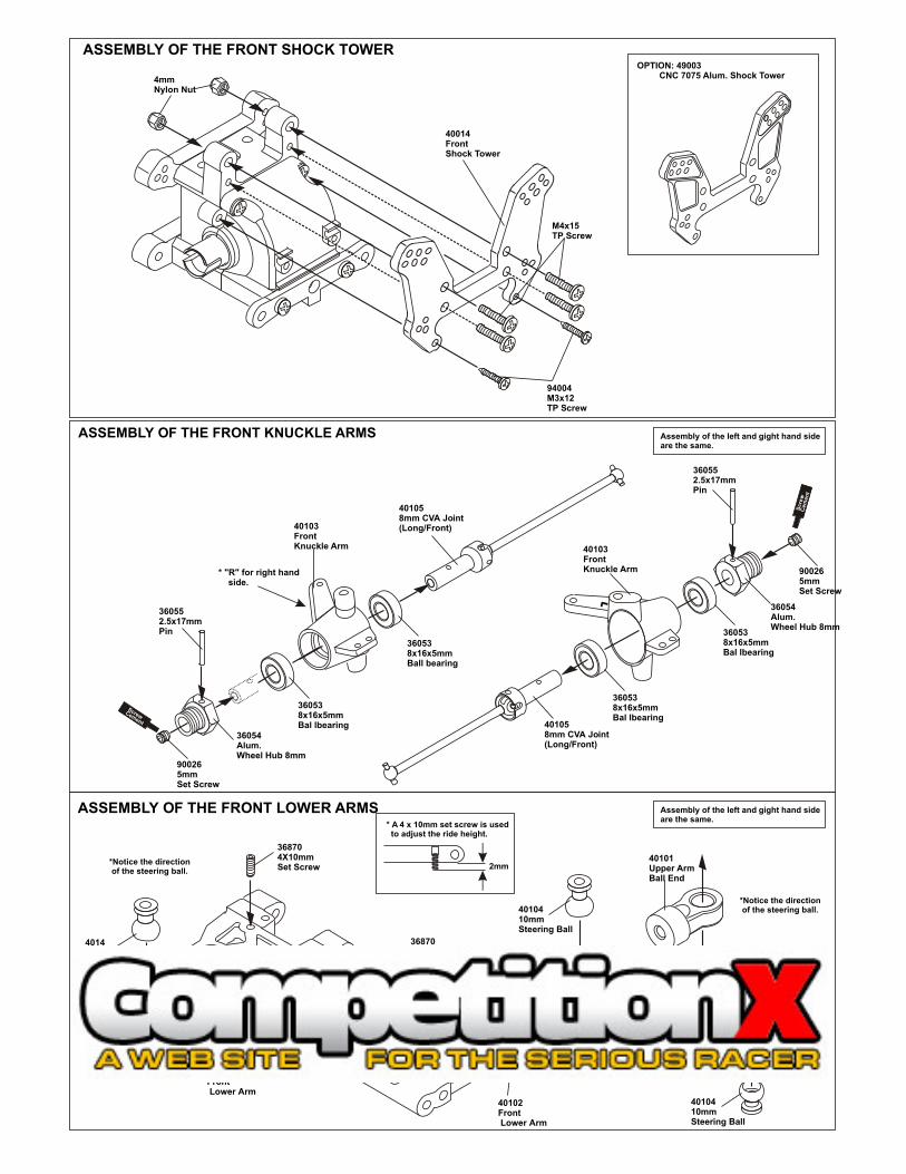
ASSEMBLY OF THE FRONT KNUCKLE ARMS
ASSEMBLY OF THE FRONT SHOCK TOWEROPTION: 49003 CNC 7075 Alum. Shock Tower
40014Front Shock Tower
LL
360538x16x5mmBal lbearing
360538x16x5mmBal lbearing
900265mmSet Screw
36054Alum. Wheel Hub 8mm
360552.5x17mmPin
Scre
w
Cem
en
t
40103FrontKnuckle Arm 40103
FrontKnuckle Arm* "R" for right hand
side.
401058mm CVA Joint(Long/Front)
401058mm CVA Joint(Long/Front)
360538x16x5mmBall bearing
360538x16x5mmBal lbearing
900265mmSet Screw
36054Alum. Wheel Hub 8mm
360552.5x17mmPin
Screw Cement
Assembly of the left and gight hand side are the same.
Assembly of the left and gight hand side are the same.
ASSEMBLY OF THE FRONT LOWER ARMS
368704X10mmSet Screw
368704X10mmSet Screw
* A 4 x 10mm set screw is used to adjust the ride height.
2mm
40102Front Lower Arm
40102Front Lower Arm
4010410mmSteering Ball
401410mmSteering Ball
4010410mmSteering Ball
4010410mmSteering Ball
40101Upper ArmBall End
40101Upper ArmBall End
*Notice the direction of the steering ball.
*Notice the direction of the steering ball.
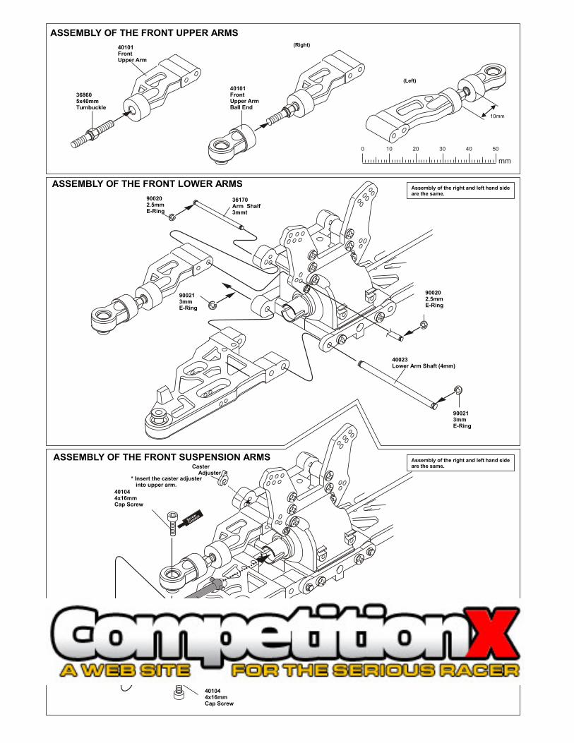
900202.5mmE-Ring
900202.5mmE-Ring
36170Arm Shalf3mmt
Assembly of the right and left hand side are the same.
Assembly of the right and left hand side are the same.
ASSEMBLY OF THE FRONT LOWER ARMS
40023Lower Arm Shaft (4mm)
900213mmE-Ring
900213mmE-Ring
ASSEMBLY OF THE FRONT SUSPENSION ARMS
368605x40mmTurnbuckle
ASSEMBLY OF THE FRONT UPPER ARMS
401044x16mmCap Screw
401044x16mmCap Screw
Screw
Cement
Screw
Cement
* Insert the drive shaft into cap joint before assembly.
40101Front Upper ArmBall End
40101Front Upper Arm
(Right)
(Left)
Caster Adjuster
* Insert the caster adjuster into upper arm.
10mm
0 10 20 30 40 50
mm
94004M3x12TP Screw
M4x15TP Screw
4mmNylon Nut
ASSEMBLY OF THE FRONT KNUCKLE ARMS
ASSEMBLY OF THE FRONT SHOCK TOWEROPTION: 49003 CNC 7075 Alum. Shock Tower
40014Front Shock Tower
LL
360538x16x5mmBal lbearing
360538x16x5mmBal lbearing
900265mmSet Screw
36054Alum. Wheel Hub 8mm
360552.5x17mmPin
Scre
w
Cem
en
t
40103FrontKnuckle Arm 40103
FrontKnuckle Arm* "R" for right hand
side.
401058mm CVA Joint(Long/Front)
401058mm CVA Joint(Long/Front)
360538x16x5mmBall bearing
360538x16x5mmBal lbearing
900265mmSet Screw
36054Alum. Wheel Hub 8mm
360552.5x17mmPin
Screw Cement
Assembly of the left and gight hand side are the same.
Assembly of the left and gight hand side are the same.
ASSEMBLY OF THE FRONT LOWER ARMS
368704X10mmSet Screw
368704X10mmSet Screw
* A 4 x 10mm set screw is used to adjust the ride height.
2mm
40102Front Lower Arm
40102Front Lower Arm
4010410mmSteering Ball
401410mmSteering Ball
4010410mmSteering Ball
4010410mmSteering Ball
40101Upper ArmBall End
40101Upper ArmBall End
*Notice the direction of the steering ball.
*Notice the direction of the steering ball.
900202.5mmE-Ring
900202.5mmE-Ring
36170Arm Shalf3mmt
Assembly of the right and left hand side are the same.
Assembly of the right and left hand side are the same.
ASSEMBLY OF THE FRONT LOWER ARMS
40023Lower Arm Shaft (4mm)
900213mmE-Ring
900213mmE-Ring
ASSEMBLY OF THE FRONT SUSPENSION ARMS
368605x40mmTurnbuckle
ASSEMBLY OF THE FRONT UPPER ARMS
401044x16mmCap Screw
401044x16mmCap Screw
Screw
Cement
Screw
Cement
* Insert the drive shaft into cap joint before assembly.
40101Front Upper ArmBall End
40101Front Upper Arm
(Right)
(Left)
Caster Adjuster
* Insert the caster adjuster into upper arm.
10mm
0 10 20 30 40 50
mm
940043X12mmTapping Screw
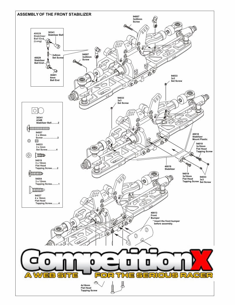
* Insert the front bumper before assembly.
40013FrontBumper
40064Chassis
30341A34BStabilizer Ball..........2
ASSEMBLY OF THE FRONT STABILIZER
940193 x 10mm Flat HeadTapping Screw........2
940274 x 16mm Flat Head Tapping Screw..........4
940073 x 20mm Screw ......................2
940043 x 12mm Tapping Screw..........1
940333 x 3mm Set Screw..............4
940073x20mmScrew
940073x20mmScrew
940333x3Set Screw
940333x3Set Screw
940333x3Set Screw
40019Stabilizer
940193x10mmFlat Head Tapping Screw
940193x10mmFlat Head Tapping Screw
40018StabilizerMount Plastic
3x8mmSet Screw40029
Stabilizer Ball End
304016mmBall End
30341Stabilizer Ball
40029StabilizerBall End(Long)
940124x20mmScrew( Small Head )
ASSEMBLY OF THE WING STAY
40027RearBody Mount
( Take the plastic part from #40027Rear Win Stay Set. )
49038Rear Shock Tower, Orange
3x12mmTapping Screw
353133mmNylon Nut
40027Wing Mount
40027Wing Mount
*Insert the 3mm nylon nut before assembly.
3x20Tapping Screw
940073x20Tapping Screw
40027Wing Stay( Left )
40027Wing Stay( Right )
40027Wing Mount
40027Wing Mount
40027Wing Stay Post
940043x12mmTapping Screw
940114x15mmTapping Screw( Small Head )
940114x15mmTapping Screw( Small Head )
3 x 20mm Tapping Screw............6
4 x 15mm Tapping Screw( Small Head )............2
4 x 15mm Tapping Screw( Small Head )............4
3mm Nylon Nut........2
3 x 12mm Tapping Screw........3
OPTION: #49004 CNC 7075 REAR SHOCK TOWER
OPTION: #49043 CNC ALIM. POSTS, WING MOUNT, ORANGE
4x16mmFlat HeadTapping Screw

940043X12mmTapping Screw
* Insert the front bumper before assembly.
40013FrontBumper
40064Chassis
30341A34BStabilizer Ball..........2
ASSEMBLY OF THE FRONT STABILIZER
940193 x 10mm Flat HeadTapping Screw........2
940274 x 16mm Flat Head Tapping Screw..........4
940073 x 20mm Screw ......................2
940043 x 12mm Tapping Screw..........1
940333 x 3mm Set Screw..............4
940073x20mmScrew
940073x20mmScrew
940333x3Set Screw
940333x3Set Screw
940333x3Set Screw
40019Stabilizer
940193x10mmFlat Head Tapping Screw
940193x10mmFlat Head Tapping Screw
40018StabilizerMount Plastic
3x8mmSet Screw40029
Stabilizer Ball End
304016mmBall End
30341Stabilizer Ball
40029StabilizerBall End(Long)
940124x20mmScrew( Small Head )
ASSEMBLY OF THE WING STAY
40027RearBody Mount
( Take the plastic part from #40027Rear Win Stay Set. )
49038Rear Shock Tower, Orange
3x12mmTapping Screw
353133mmNylon Nut
40027Wing Mount
40027Wing Mount
*Insert the 3mm nylon nut before assembly.
3x20Tapping Screw
940073x20Tapping Screw
40027Wing Stay( Left )
40027Wing Stay( Right )
40027Wing Mount
40027Wing Mount
40027Wing Stay Post
940043x12mmTapping Screw
940114x15mmTapping Screw( Small Head )
940114x15mmTapping Screw( Small Head )
3 x 20mm Tapping Screw............6
4 x 15mm Tapping Screw( Small Head )............2
4 x 15mm Tapping Screw( Small Head )............4
3mm Nylon Nut........2
3 x 12mm Tapping Screw........3
OPTION: #49004 CNC 7075 REAR SHOCK TOWER
OPTION: #49043 CNC ALIM. POSTS, WING MOUNT, ORANGE
4x16mmFlat HeadTapping Screw
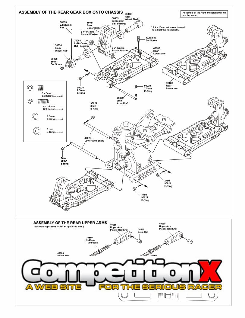
ASSEMBLY OF THE REAR UPPER ARMS
368605x40mmTurnbuckle
368605x40mmTurnbuckle
368507mm Ball
368507mm Ball
368507mm Ball
(Make two upper arms for left an right hand side. )40065Upper ArmPlastic Rod End
40065Upper ArmPlastic Rod End
40065Upper ArmPlastic Rod End
40065Upper ArmPlastic Rod End
16mm
40023Lower Arm Shaft
900213mmE-Ring
3mm90021E-Ring
3mm90021E-Ring
3mm90021E-Ring
3mm90021E-Ring
900202.5mmE-Ring
900202.5mmE-Ring
4X10mmSet Screw
361703mmArm Shaft
360538x16x5mmBall bearing
360538x16x5mmBal l bearing
900265mmSet Screw
360548mmWheel Hub
360552.5x17mmPin
36081Rear Upper Right
36082Rear Wheel Shaft
3 x10x3mmPlastic Washer
3 x10x3mmPlastic Washer
Assembly of the right and left hand side are the same.
4 x 10 mm Set Screw...........2
5 x 5mm Set Screw............2
2.5mm E-Ring..........4
3 mmE-Ring..........4
* A 4 x 10mm set screw is used to adjust the ride height.
40102Rear Lower arm
40102Rear Lower arm
ASSEMBLY OF THE REAR GEAR BOX ONTO CHASSIS
40107Rear Driver Shaft (101mm)
* Insert rear driver shaft before assembly.
ASSEMBLY OF THE REAR AND ANTI-ROLL BAR
940333x3Set Screw
940333x3Set Screw
940333x3Set Screw
940193X10mm Flat HeadScrew
940193X10mm Flat HeadScrew
40019Stabilizer
40018StabilizerMount Plastic
30341Stabilizer Ball..........2
940193 x 10mm Flat HeadTapping Screw........2
940073 x 20mm Screw ......................2
940203 x 12mm Tapping Screw..........1
940333 x 3mm Set Screw..............2
940073 x 20mm Cap Screw..........2
900183 X 25mm Cap Screw.........2
35313M3 Nylon Nut..........2
940333 x 3mm Set Screw..........2
940353 x 8mm et Screw..........2.
940073x20mmScrew
940073x20mmScrew
353133mmNylon Nut
353133mmNylon Nut
3 x 25mmCap Screw
940073 x 20mmCap Screw
Rear Upper ArmAssembly
Assembly of the right and left hand side are the same.
3x8mmSet Screw40029
Stabilizer Ball End
304016mmBall End
30341Stabilizer Ball
40166StabilizerBall End(Long)

ASSEMBLY OF THE SERVO SAVER
M3 Nut
* Put the 3mm nut before assembly.
40031Servo SaverHorn A 40095
Servo SaverConnecting Plate,Orange
6x10mmPlasticBushing
6x10mmPlasticBushing
Servo SaverHorn C
4x8mmPlastic flangeBushing
40037Steering Plate Hex Screw
40037Steering Plate Hex Screw
40035Servo SaverAlum. AxleTube
40031Servo SaverHorn B
40033Servo SaverSpring
40034Servo Saver Spring TensionAdjuster
40036servo SaverPost
40036Servo SaverPost40074
6x10mmBall bearing
35313M3 Nut..........1
4x10mmScrew..........2
* Take the 4x8mm Plastic Flange bushing and Plastic Bushing from servo saver plastic parts tree
OPTION: #49014 CNC BALL BEARING AXLE TUBE
Option:400734x8mmBall bearingflange
40037Steering Plat Hex Screw....... 2
Option:400746x10mmBall bearing
940274 x 16mm Flat Head Tapping Screw..........4
940274 x 16mm Flat Head Tapping Screw
40064Chassis
4x10mmFlat HeadScrew
4x10mmScrew
4x15mmTapping Screw
40027Front BodyPost
3x12mmScrew
* Assembly the front body post before assembly the Front Plate.
ASSEMBLY OF THE SERVO SAVER ONTO THE CHASSIS
400184x56mmTurnbuckle
400184x56mmTurnbuckle
368507mm Ball
368507mm Ball
368507mm Ball
36700SteeringBall End
36700SteeringBall End
36700SteeringBall End
353133mmNylon Nut
400393mm Tapper Washer(Alum.)
400393mm Tapper Washer(Alum.)
40039Alum. Tapper Washer................4
3x15mmFlat Head Screw
3x15mmFlat Head Screw
ASSEMBLY OF THE FRONT STEERING ROD
35313M3 Nylon Nut..........2
940213 x 15mm Flat Head Screw..........4
40030Front Plate
940094x10mmScrew..........2
940043 x 12mm Tapping Screw..........1
940114 x 15mm Tapping Screw( Small Head )............2
940264 x 10mmFlat Head Screw..........2
Assembly of the right and left hand side are the same.
* Anticlockwise mark.
35.5mm
* Made two steering rods for left and right hand side.
OPTION:49005CNC 7075 Alum. Front Plate 49019Graphite Front Plate
0 10 20 30 40 50
mm

* Take off the double sided paper before assembly.
ASSEMBLY OF THE BRAKE AND SPLIT CENTER DIFF. MOUNT* Make brake pads for each side.
36660Brake Pad
36661Brake Padlinings
40044Brake PadSpring
40044Brake PadSpring
40044Brake PadSpring
40044Brake PadSpring
40045Brake PadAdjustment Screw
40045Brake PadAdjustment Screw
40043Center Diff. MountPost
40040Break DiscHolder
40040Brake DiskHolder
40040Brake DiscHolder
40040Center Diff.Mount40040
Center Diff.Mount
40040Center Diff.Mount
40040Center Diff.Mount
40045Brake Pad Screw...........4
40044Brake Pad Spring.........8
40043Center Diff. Mount Post...........................4
Large Hole
Small Hole
Assembly the brake disc holder in the direction shown.
*Towards the front.
*Towards the Rear.
Small hole to theOutside.
OPTION: #49030 CNC 7075 SPLIT CENTER DIFF MOUNT.
40042Brake Disk
40042Brake Disk
40042Brake Disk 40042
Brake Disk
ASSEMBLY OF THE CENTER DIFF. INTO CENTER DIFF. MOUNT
Center Diff. Assembly
3x3mmSet Screw
3x3mmSet Screw
3x10mmScrew
40031Fuel Overflow Proof Plate
30213Brake Cam
30211Plastic Bushing
Option302125X8mmBall Bearing
40096Center Diff.Plate, Orange
30171Brake Lever
30171Brake Lever..........2
30171Brake Lever
3x10mmScrew
940033x10mmScrew..........4
940333 x 3mm Set Screw..............2
Put the front brake lever asShown.
OPTION: #49008 GRAPHITE BRAKE DISKS, 2PCS.
OPTION: #49018 GRAPHITE TOP CENTER PLATE
Screw Cement
Screw Cement

ASSEMBLY OF THE RECEIVER BOX
* Use the screw provided with your radio
10280Switch Cover
Switch, Provided by Radio
40047Receiver Box
40047Receiver BoxCover
40047Receiver Box
2x10mmTapping Screw
408982x25mmScrew
Receiver
Battery Case, Provided byRadio
30560AntennaPipe
940033 x 10mm Tapping Screw..........1
3x10mmScrew
2 x 25mm Screw.....1
2 x10mm Tapping Screw..........2
Option:10212Hump PackBattery
*Use the original battery case or rechargeable hump pack battery.
* You must add padding for radioand battery once lid is closed.Do not let radio and/or battery beloose in box.
40028Center Drive Shaft (93mm)
40028Center Drive Shaft (93mm)
4x12mmFlat Head Screw
3x25mmCap Screw
3mmNylon Nut
40018Center ChassisBrace( Rear )
40018Center Chassis Brace( Front )
3x12mmScrew
4x16mmFlat HeadTapping Screw
4x16mmFlat HeadTapping Screw
4x16mmFlat HeadTapping Screw
2.6x10mmFlat HeadTapping Screw
353133mm Nylon Nut........1
940043 x 12mm Tapping Screw........3
900193 X 25mm Cap Screw.........1
940264 x 12mmFlat Head Screw..........2
940274 x 16mm Flat Head Tapping Screw..........4
ASSEMBLY OF THE CENTER DIFF. ONTO CHASSIS
ASSEMBLY OF THE CENTER STIFFENERONTO CHASSIS
OPTION: 49015CNC Alum. Chassis Brace Set
ASSEMBLY OF THE STONE GUIDE
40046Stone Guard
40046Stone Guard
3x10mmScrew
3x10mmScrew
3x10mmScrew
Assembly of the right and left hand side are the same.
3 x 10mm Tapping Screw..........6
OPTION:Stone GuardYellow . 40078Red . 40079Lime . 40080Blue . 40081Black . 40046

3x10mmFlat HeadTapping Screw
* Use 4 pcs for receiver box.
* Use 4 pcs for radio tray.
3x10mmFlat HeadTapping Screw
40027Radio Tray Post( Plastic )
40027Radio Tray Post( Plastic )
3x12mmTapping Screw
10274Servo Post
Servo Post
3x10mmTapping Screw
3x10mmTapping Screw
3x10Tapping Screw
3x10Tapping Screw
* Take the servo post from servo saver plastic part tree.
ASSEMBLY OF THE RADIO TRAY
940193 x 10mmFlat HeadTapping Screw.........8
940033 x 10mm Tapping Screw..........14
Throttle Servo
Steering Servo
*Connect as per radio.
49039Alum.Radio Tray, Orange
3X10mmTapping Screw
40031TransponderHolder
OPTION: 49017 GRAPHITE RADIO TRAY.
OPTION:49044 CNC ALUM. POST, RADIO TRAY, ORANGE
3 X 8mm Washer
3mm Nylon Locknut
3 x 5mm Screw
3 x 20mm Cap Screw
* Place the clutch shoes with the clutch springs over the 3 pins of the flywheel. Using a screw driver as a lever, bend the small end of the clutch spring behind the clutch nut and press down to snap shoe in place.
* Fit the flywheel using a crosswrench or deep socket.
If engine turns when tightening,hold piston with large thick tie-wrapsand hard wood in exhaust port. Do not use metal, it will damage engine.
#10098SG Nut & Shim KiT
ASSEMBLY OF THE CLUTCH INTO ENGINE
3 x 10mmTapping Screw
#10016Air FilterSpongeRefills
#10017 - Blue#10018 - Yellow#10019 - Rose#10034 - ChromeFoam Air filters Unit
#10013 - Mount Wire
#10021 - Black#10027 - Yellow#10028 - Pink#10029 - BlueAir Filter Connector
Nylon Strap ( Small )
Nylon Strap ( Small )
You must oil foam filter before use.Filter will not work if not oiled.
Clean with soap and water only.You will damage foam if washedif fuel!
ASSEMBLY OF THE AIR FILTER
#10102Clutch Spring
#10010Clutch ShoesBlack Type
* Shoes are trailing.
3 x 8mmWasherMisc. Hardware#10099
#341105x10x4mmBall Bearing
#341105x10x4mmBall Bearing
#10040 (stock)3 PinFlywheel, Taper#100433 PinFlywheel, Fan
#10091Clutch Nutscrew type
3 x 5mmScrew
#10330Brass, Corn(large hole)
#10329Brass, Corn(sml hole)
304813 x 20mmHex Screw
304813 x 20mmHex Screw
304813 x 20mmHex Screw
#30480Engine Mount
#10398 - 12T#10399 - 13T#10400 - 14T (stock)#10401 - 15T#10402 - 16T#10403 - 17T#10404 - 18TClutch Bells
SEE NOTESABOVE#10048OR 10049
Notes:Non-Pull Start Engines...• Alum. Washer behind the flywheel is not needed when using Force engines or similar types. O.S. Engines will require washer spacer.
• To check!..place the brass corn against the engine bearing, then flywheel. You should be covering one or two thread of the engine shaft. If this is the case, you do not need an additional washer behind the flywheel.
You must cut the engine shaft if too long. Count 6 threads in front of the flywheel and mark. This is all you need to tighten the clutch nut and mount the flywheel.
Force Pull Start Engine w/threaded shalf...• Force Pull Start Engines required NO spacer and no shaft cutting. The engines comes with an alum cast driver washer, you use this part as the spacer, not the alum. washer shown. Also, use the special flywheel brass corn. This corn fits the thread shaft diameter so you can tighten the flywheel against the drive hub.
NoteSG Shaft
ThreadedShaft
Options
Clutch Spring10100 - Springs, Polished, Med.10101 - Spring, Gray, Hard10102 - Spring, Black, Stock
Clutch Shoes, 3 shoe clutch10010 - Shoes, Carbon Material, Black10011 - Shoes, Alum. CNC Blue, Lite Weight10012 - Shoe, Alum. CNC Purple, Med. Weight
Option10799Flywheel Wrench

3x10mmFlat HeadTapping Screw
* Use 4 pcs for receiver box.
* Use 4 pcs for radio tray.
3x10mmFlat HeadTapping Screw
40027Radio Tray Post( Plastic )
40027Radio Tray Post( Plastic )
3x12mmTapping Screw
10274Servo Post
Servo Post
3x10mmTapping Screw
3x10mmTapping Screw
3x10Tapping Screw
3x10Tapping Screw
* Take the servo post from servo saver plastic part tree.
ASSEMBLY OF THE RADIO TRAY
940193 x 10mmFlat HeadTapping Screw.........8
940033 x 10mm Tapping Screw..........14
Throttle Servo
Steering Servo
*Connect as per radio.
49039Alum.Radio Tray, Orange
3X10mmTapping Screw
40031TransponderHolder
OPTION: 49017 GRAPHITE RADIO TRAY.
OPTION:49044 CNC ALUM. POST, RADIO TRAY, ORANGE
3 X 8mm Washer
3mm Nylon Locknut
3 x 5mm Screw
3 x 20mm Cap Screw
* Place the clutch shoes with the clutch springs over the 3 pins of the flywheel. Using a screw driver as a lever, bend the small end of the clutch spring behind the clutch nut and press down to snap shoe in place.
* Fit the flywheel using a crosswrench or deep socket.
If engine turns when tightening,hold piston with large thick tie-wrapsand hard wood in exhaust port. Do not use metal, it will damage engine.
#10098SG Nut & Shim KiT
ASSEMBLY OF THE CLUTCH INTO ENGINE
3 x 10mmTapping Screw
#10016Air FilterSpongeRefills
#10017 - Blue#10018 - Yellow#10019 - Rose#10034 - ChromeFoam Air filters Unit
#10013 - Mount Wire
#10021 - Black#10027 - Yellow#10028 - Pink#10029 - BlueAir Filter Connector
Nylon Strap ( Small )
Nylon Strap ( Small )
You must oil foam filter before use.Filter will not work if not oiled.
Clean with soap and water only.You will damage foam if washedif fuel!
ASSEMBLY OF THE AIR FILTER
#10102Clutch Spring
#10010Clutch ShoesBlack Type
* Shoes are trailing.
3 x 8mmWasherMisc. Hardware#10099
#341105x10x4mmBall Bearing
#341105x10x4mmBall Bearing
#10040 (stock)3 PinFlywheel, Taper#100433 PinFlywheel, Fan
#10091Clutch Nutscrew type
3 x 5mmScrew
#10330Brass, Corn(large hole)
#10329Brass, Corn(sml hole)
304813 x 20mmHex Screw
304813 x 20mmHex Screw
304813 x 20mmHex Screw
#30480Engine Mount
#10398 - 12T#10399 - 13T#10400 - 14T (stock)#10401 - 15T#10402 - 16T#10403 - 17T#10404 - 18TClutch Bells
SEE NOTESABOVE#10048OR 10049
Notes:Non-Pull Start Engines...• Alum. Washer behind the flywheel is not needed when using Force engines or similar types. O.S. Engines will require washer spacer.
• To check!..place the brass corn against the engine bearing, then flywheel. You should be covering one or two thread of the engine shaft. If this is the case, you do not need an additional washer behind the flywheel.
You must cut the engine shaft if too long. Count 6 threads in front of the flywheel and mark. This is all you need to tighten the clutch nut and mount the flywheel.
Force Pull Start Engine w/threaded shalf...• Force Pull Start Engines required NO spacer and no shaft cutting. The engines comes with an alum cast driver washer, you use this part as the spacer, not the alum. washer shown. Also, use the special flywheel brass corn. This corn fits the thread shaft diameter so you can tighten the flywheel against the drive hub.
NoteSG Shaft
ThreadedShaft
Options
Clutch Spring10100 - Springs, Polished, Med.10101 - Spring, Gray, Hard10102 - Spring, Black, Stock
Clutch Shoes, 3 shoe clutch10010 - Shoes, Carbon Material, Black10011 - Shoes, Alum. CNC Blue, Lite Weight10012 - Shoe, Alum. CNC Purple, Med. Weight
Option10799Flywheel Wrench

101145mm Hex Screw for Engine Mount
38120Fuel TankPost
* Take the fuel tank post from 40047 plastic parts tree.
3x3mmSet Screw
40050Muffler MountingPost
40051MufflerWire
INSTALLATION OF THE FUEL TANKAND ENGINE ONTO CHASSIS
3X15mmTapping Screw
3X15mmTapping Screw
40066Pressure Nipple
40109Fuel Tank, 140+cc
40066Fuel Nipple
3x10mmTapping Screw
3x10mmTapping Screw
ASSEMBLY OF THE MANIFOLD ANDMUFFLER* Read this page very carefully.
4x10mmFlat HeadScrew
5x5mm or 4x4mmSet Screw
* Tighten the strip and cut off the excess.
* Drill a hole (Size 3.5mm) in the place and align as shown. Use a two part epoxy glue to full seal the nipple base to the nipple.
3x20mmCap Screw
Note Book Paper
* Use note book paper to set gear backlash between spur gear and clutch bell. If the space is not correct the spur gear will be damaged.
Spur Gear
Clutch Bell90 Degree
* Loose or tighten 3x20mm cap screw and 5x10mm hex screw to align spur gear and clutch bell gear to 90 degree.
* Assemble the fuel tank post before assembling the fuel nipple.
#10069Manifold Adapter( Red Silicone ) #31991
Manifold, Polished
#10120 ManifoldSpring
#10184Blue, Silicone Tube
#10079Alum. CNCPressure Nipple
#31992Dual Chamber, Polished
Option:10182Silicone Tube, Red10183Silicone Tube, Yel.10184Silicone Tube, Blue
ASSEMBLY OF THE BRAKE LINKAGE
3x3mmSet Screw
3x3mmSet Screw
3x3mmset screw
10300Alum. Stopper
10300Alum. Stopper
ThrottleSlider
2mmRod
Plastic Collar
Throttle Spring
30530ThrottleBall End
ServoMount
* Cut the shaded area as shown.
3x25mmScrew
AdjustMount
361402mmAdjust Mount
2mm Rod
2mm Rod
2mmTie-RodEnd
2x6mmWasher
2x6mmWasher
2x4mmScrew
2x4mmScrew
2mmNut
2x8mmScrew
* Cut the shaded area as shown.
3x10mmScrew
10768Servo Horn, Yel.
#30800Brake System Plastic Parts Set
ASSEMBLY OF THE FRONT STEERING ROD
16mm
* Align the steering servo as shown.
Parallel
* Use the screw provided with your servo.
10768Servo Horn
304116mmBall
304116mmBall
3x10mmScrew
3x15mmScrew
353133mmNylon Nut
306903x30mmTie Rod
304106mmTie Rod End
304106mmTie Rod End
* Enlarge this hole.
0 10 20 30 40 50
mm

10300Alum. Stopper
ASSEMBLY OF THE BRAKE LINKAGE INTOBRAKE ROD
*use the screw provided With your radio.
USING BREAK ADJUST NUT
3X3mmSet Screw
5mmFuelTube
5mmFuelTube
Brake
Idle Position
Full Throttle
* Align throttle servo same as shown.
*Snap On.
TightenLess Brake
LoosenMore Brake
TightenLoosen
* Tighten or loose the adjuster nut will change the brake.
ALIGN THROTTLE SERVO AND BRAKE SAME AS SHOWN
Brake is not on
Engine at idle
( Neutral Position )
Brake is on
Brake Adjust Nut
( Braking Position )
Brake is not on
Engine at full throttle
( Full Throttle Position )Less Brake
More Brake
TightenLoose
* Tighten or loose the adjuster nut will change the brake.
2. Pull down piston, attach pressure top and shock oil overflow with tissue paper.
SHOCK ASSEMBLY
FILLING THE SHOCKS WITH OIL
ASSEMBLY OF THE SPRING
1. Pull down piston and pour oil into shock cylinder. Remove air bubbles by slowly moving piston up and down. 3. Tighten up shock cap.
*Move Slowly.
*Leave 3mm.
OIL
Oil Seal
322377mm R-Ring
* Push 6mm ball joint into ball end.
2.6 x 5mmWasher
40069BlackShock Spring
40063Spring Holder
OPTION:40063 - CNC Alum Spring Holder, Orange
304116mm Ball
32033Pressure Top
40093Shock CapHard Coated
* Fit into the groove.
* Assembly 2 pieces of the shock shaft for front and rear.
40054Short Shaft
40055Short Shaft
* Long shaft for rear.
down.
UP
* Be careful not to damage shock shaft.
* Short shaft for front.
Make a PAIR for rear
4. Assembly the dust cover.
* Cut 6mm for front.
400602.5mm Nylon Nut
32235Shock Piston
40076Shock Cylinder
40077Shock Cylinder
322371mm Washer
322372mm Washer
Make a PAIR for front
Fit the O-ring into groove.
49041Spring Adjuster,Orange
49041Spring Adjuster,Orange
J-47C Spring Adjuster....4
4005914.7mm O-Ring
322373.5mm O-Ring
40058Shock Shaft Dust Cover
32235Shock Piston.........4
4005914.7mm O-Ring....4
322371mm Washer.............4
322372mm Washer..........4
400602.5mm Nylon Nut........4
40056Shock Plastic Rod End
40056Shock Plastic Rod End
40052 - Front Shock Set40053 - Rear Shock Set
OPTION:40069 - Black, Stock, Spring Set40070 - Green, Soft Set40071 - Blue, Med. Set40072 - White, Hard Set
APPLY OIL TO SHOCK BODY BEFORE INSTALLING COLLAR
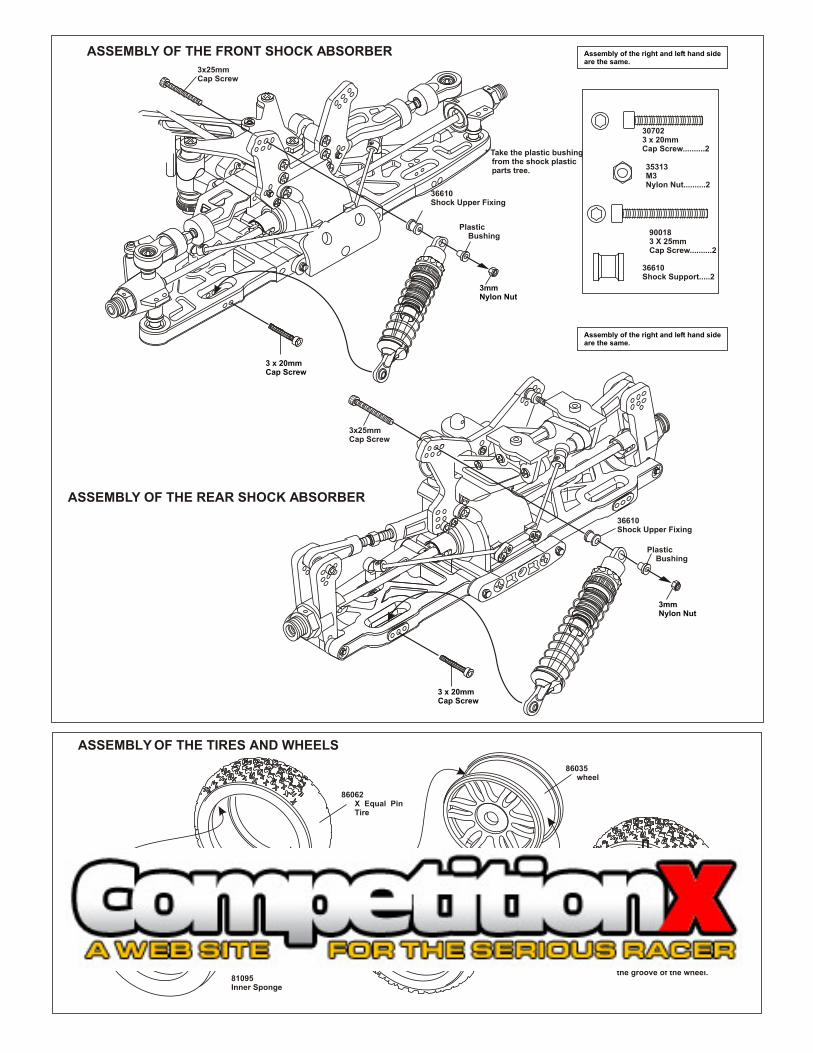
ASSEMBLY OF THE TIRES AND WHEELS
INSTANT
GLUE
* Apply instant glue into the groove of the wheel.
86062 X Equal Pin Tire
81095Inner Sponge
86035 wheel
25mm
25mm
0510152025 5 10 15 20 25
ASSEMBLY OF THE WING
* Drill two 7mm holes for mounting.
3x12mmScrew
40027CountersunkPlastic Washer
*Upper Deck Of The Wing.
40084Wing, Yellow
40083 - Wing White40084 - Wing Yellow40085 - Wing Red40086 - Wing Lime40087 - Wing White
86044 - Red86045 - White86046 - Lime86047 - Yellow86048 - Black86049 - Chrome17mm Dual Spoke, 2 pairs (4 wheels) per Bag.
* Check the hole spacing on the underside.
OPTION:49045CNC Alum. Wing WasherOrange, 2 pcs.
3 x 20mmCap Screw
3mmNylon Nut
Plastic Bushing
36610Shock Upper Fixing
36610Shock Upper Fixing
36610Shock Support.....2
3x25mmCap Screw
3 x 20mmCap Screw
3mmNylon Nut
Plastic Bushing
3x25mmCap Screw
ASSEMBLY OF THE FRONT SHOCK ABSORBER
ASSEMBLY OF THE REAR SHOCK ABSORBER
Assembly of the right and left hand side are the same.
Assembly of the right and left hand side are the same.
35313M3 Nylon Nut..........2
307023 x 20mm Cap Screw..........2
900183 X 25mm Cap Screw..........2
* Take the plastic bushing from the shock plastic parts tree.
Assembly of the right and left hand side are the same.
30051Wheel Nut
30051Wheel Nut
ASSEMBLY OF THE WHEELS ONTO FRONT KNUCKLE ARM AND REAR HUB

31149Body Clips
31149Body Clips
MOUNTING THE BODY
3x12mmScrew
3x12mmScrew
3x12mmScrew
3x12mmScrew
FOR A STICK PACK BATTERY
40048Stick PackBattery Holder(5 Cell)
Stick PackBattery(5 Cell)( Not Included.)
* Use tape to secure the battery.
* Insert battery wire into receiver and connect to the switch.
Tape
40048Battery HolderMount
40048Battery HolderMount
Adjustable width, lower arms.Simply cut outside 330mm pinholes.
310mm
330mm
CHANGING WIDTH FROM 330mm TO ROAR LEGAL 310mm
Soft Firm
Soft Firm
SET-UP GUIDE
RIDE HEIGHT ADJUSTMENT
2mmHex Screw
Use a 2mm hex screw to adjust the ride height.Screwing in the 4x10mm set screw....Ride height becomes lower.Uncsrewing the 4x10mm set screw..Ride height becomes higher.
1 2 3
1 2
Leave as much plastic as possible

31149Body Clips
31149Body Clips
MOUNTING THE BODY
3x12mmScrew
3x12mmScrew
3x12mmScrew
3x12mmScrew
FOR A STICK PACK BATTERY
40048Stick PackBattery Holder(5 Cell)
Stick PackBattery(5 Cell)( Not Included.)
* Use tape to secure the battery.
* Insert battery wire into receiver and connect to the switch.
Tape
40048Battery HolderMount
40048Battery HolderMount
Adjustable width, lower arms.Simply cut outside 330mm pinholes.
310mm
330mm
CHANGING WIDTH FROM 330mm TO ROAR LEGAL 310mm
Soft Firm
Soft Firm
SET-UP GUIDE
RIDE HEIGHT ADJUSTMENT
2mmHex Screw
Use a 2mm hex screw to adjust the ride height.Screwing in the 4x10mm set screw....Ride height becomes lower.Uncsrewing the 4x10mm set screw..Ride height becomes higher.
1 2 3
1 2
Leave as much plastic as possible

STARTING OF THE ENGINE
How to start the engine: 1. Turn on transmitter and then receiver. 2. Fill fuel tank with fuel bottle. 3. Connect 1.2V glow plug starter. 4. Start engine with 12V starter or starter box ( Note the direction of the starter.) 5. After the engine be started, remove the 1.2V glow plug starter.
1.2VGlow PlugStarter
* Follow the engine manufacturer instruction manuals regarding engine set-up, carburetor and maintenance.
Connect with 12V battery
* Note the direction of the starter.
Rubber wheel turns engineflywheel.
12V Starter
* To start the engine, use hand held startermotor or starter box.
#10250Starter Box
ENGINE BREAK-IN AND TUNNING(BREAK-IN THE ENGINE BEFORE DRIVING THE CAR!)
OPTIONAL OFNA CAR STANDS• Choose a wide clear outdoor location with low dirt and dust.• Set the car on box or holder with wheels off the ground.• Turn on radio and car. Make sure throttle is at idle position.• Fill fuel tank and set master engine needle.• Prime fuel line and Heat glow plug before pull starting engine.• When started, let engine fast idle for two tanks of fuel.
WOOD BLOCK

TUNING AFTER BREAK-IN
Idle adjuster screw &Barrel Stop
Lean Rich
Close master needle by turning clockwise until it stops. Then open needle by turning counterclockwise 3 turns (rich setting). When running car, adjust carb with 1/8 clockwise turns,
slowly leaner, until the top speed good. Check engine temp, if possible, for no more 250 degrees.
Adjust barrel stop so it will not close, accept for a small gap. This gap will be the idle setting. You will notice the idle will increase with a wide gap.
Adjust low end needle for best throttle response. Use only small turns. From idle, give it full throttle, if throttle is slow lean out needle until good.
APPENDIX PAGES

NOTICE:
SOME VIOLATOR RTR KITS WILL COME WITH “SHAFT START” (same as Rotor Start). THEREFORE, A PULL START ENGINE IS NOT USED AND THE SHAFT START BACK PLATE IS ALREADY INSTALLED.
BEFORE YOU CAN USE THE SHAFT START MOTOR HANDLE, YOU MUST FIRST GET OR BUY A STANDARD 7.2 BATTERY PACK.
AFTER POWERING UP THE MOTOR HANDLE, INSERT THE SPECIAL DOG BONE SHAFT AND TURN OVER THE ENGINE.
CHECK BEFORE STARTING:
1) IS THE FUEL LINE PRIMED?
2) IS THE CARBURETOR SET FOR BREAK-IN SETTINGS?
3) IS THE RADIO ON AND THROTTLE AND BRAKE LINKAGE CHECKED AND OKAY TO START?
4) MAKE SURE RADIO AND CAR RECEIVER BATTERY ARE ON AND WORKING WITH GOOD POWER.
5) PLACE THE GLOW HEATER ON PLUG.
6) HOLD THE CAR AND STARTUP THE ENGINE, BY PUMPING THROTTLE SLIGHTLY. DO NOT HIGH REV ENGINE WHEN IT STARTS, AT THIS TIME!
SHAFT START