Embed Size (px)
Citation preview
OFFSHOREVersion 2.2
williamhackett.co.uk
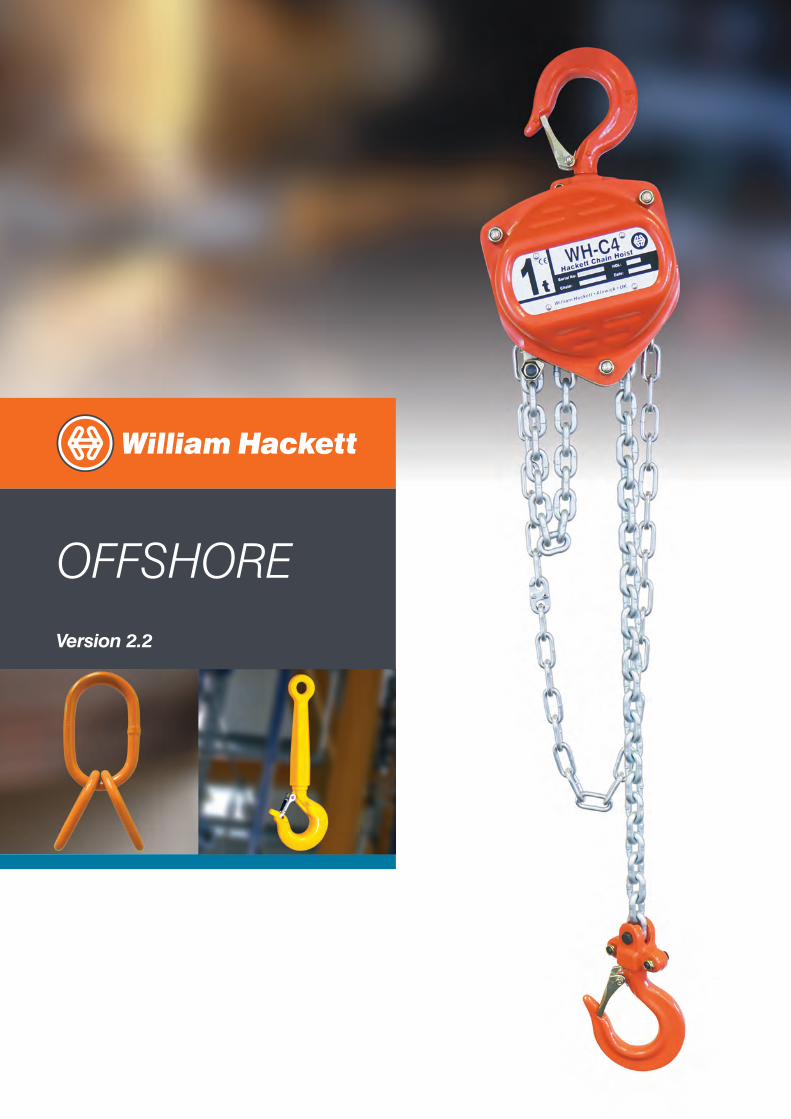
All of the business activities of William Hackett are controlled within a quality management system certified in accordancewith ISO 9001.
William Hackett has developed market leading product traceability and certification systems to ensure the complete fulfilment of all customer quality requirements.
William Hackett is proud to be a Lifting Equipment Engineers Association Full Member.
Please consider the environment when it comes to disposing of this brochure.Please recycle when you are finished with this item. For more information please visit: www.recycle-more.co.uk
Contents
HA Master Links 2HA Quad Assemblies 3
DNV Welded Chain Slings 4DNV Type Approved Shackles 6DA Grade 6 Shackle 8DA Grade 8 Shackle 9DA Swivel Self Locking Hook 10
SS-C4 / CP-C4 Anti-Corrosion Topside and Subsea Chain Block 11Design Features 12Specifications and Dimensions 13Anti-Corrosion Push, Geared and Combined Chain Blocks and Trollies 14
ROV Subsea Chain Block 17Design Features 18Specifications and Dimensions 19
SS-L5 Topside and Subsea Lever Hoist 21Design Features 22Exploded Diagram and Parts List 24Specifications and Dimensions 26
William Hackett C4 Chain Block 27Design Features 28Exploded Diagram and Parts List 30Specifications and Dimensions 32Hackett Combined Chain Block and Trollies, and Push and Geared Trollies 33WH-BC Fixed Jaw Super Clamp 36Hackett Hand Winch 38
William Hackett L4 Lever Hoists 39Design Features 40Exploded Diagram and Parts List 42Specifications and Dimensions 44
ATEX Hoisting Range 45ATEX Chain Block 46ATEX Lever Hoist 47ATEX Trollies 48ATEX Combined Chain Block and Trollies 50
Offshore and Subsea Equipment 51Forged Alloy Wide Body Shackle 52ROV Anchor Shackle 53ROV Anchor Shackle with Fishtail Handle and Safety Pin 54ROV Anchor Shackle with D Handle and Safety Pin 55ROV Eye Sling Hook 56ROV Shank Hook 57Swivel Hoist Ring Metric Thread - type 231 58Swivel Hoist Ring UNC Thread - type 232 59Swivel Hoist Ring with Alloy Steel Washer - Metric - type 203 60Swivel Hoist Ring with Alloy Steel washer - UNC - type 204 61Lifting Points metric thread 62Lifting Points UNC thread 63Yoke Snatch Block with captive shackle 64Spelter Wire Rope Sockets 66Contact Angular Swivels 68
Terms and Conditions 72
PRODUCT SUPPORT: William Hackett is fully committed to providing its customers with technical and service support through the product lifecycle, including the availability of spares and replacement components.
All statements, technical information, advice and recommendations contained within this brochure are believed to be reliable, although no guarantee is given as to their accuracy and/or completeness. The user of our products must determine the suitability of the products for their own particular purpose, either alone or in combination with other products and shall assume all risk and liability in connection with those decisions. Whilst every effort has been made to ensure accuracy in relation to the content of tables, the information contained does not form any part of any contract.
© William Hackett 2017
1e: [email protected]: 01665 604200 f: 01665 604204
Master Links and Quad Assemblies
williamhackett.co.uk
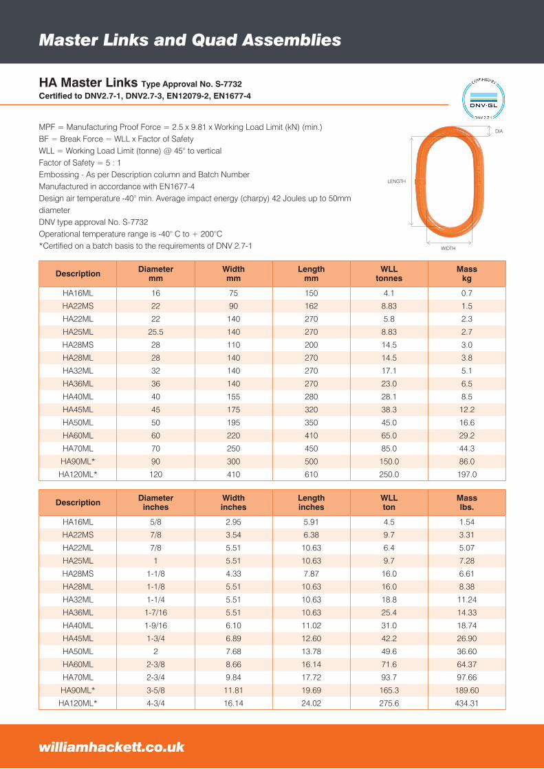
HA Master Links Type Approval No. S-7732Certified to DNV2.7-1, DNV2.7-3, EN12079-2, EN1677-4
Description Diametermm
Widthmm
Lengthmm
WLLtonnes
Masskg
HA16ML 16 75 150 4.1 0.7
HA22MS 22 90 162 8.83 1.5
HA22ML 22 140 270 5.8 2.3
HA25ML 25.5 140 270 8.83 2.7
HA28MS 28 110 200 14.5 3.0
HA28ML 28 140 270 14.5 3.8
HA32ML 32 140 270 17.1 5.1
HA36ML 36 140 270 23.0 6.5
HA40ML 40 155 280 28.1 8.5
HA45ML 45 175 320 38.3 12.2
HA50ML 50 195 350 45.0 16.6
HA60ML 60 220 410 65.0 29.2
HA70ML 70 250 450 85.0 44.3
HA90ML* 90 300 500 150.0 86.0
HA120ML* 120 410 610 250.0 197.0
MPF = Manufacturing Proof Force = 2.5 x 9.81 x Working Load Limit (kN) (min.)BF = Break Force = WLL x Factor of SafetyWLL = Working Load Limit (tonne) @ 45° to verticalFactor of Safety = 5 : 1Embossing - As per Description column and Batch NumberManufactured in accordance with EN1677-4Design air temperature -40° min. Average impact energy (charpy) 42 Joules up to 50mm diameterDNV type approval No. S-7732Operational temperature range is -40° C to + 200°C*Certified on a batch basis to the requirements of DNV 2.7-1
Description Diameterinches
Widthinches
Lengthinches
WLLton
Masslbs.
HA16ML 5/8 2.95 5.91 4.5 1.54
HA22MS 7/8 3.54 6.38 9.7 3.31
HA22ML 7/8 5.51 10.63 6.4 5.07
HA25ML 1 5.51 10.63 9.7 7.28
HA28MS 1-1/8 4.33 7.87 16.0 6.61
HA28ML 1-1/8 5.51 10.63 16.0 8.38
HA32ML 1-1/4 5.51 10.63 18.8 11.24
HA36ML 1-7/16 5.51 10.63 25.4 14.33
HA40ML 1-9/16 6.10 11.02 31.0 18.74
HA45ML 1-3/4 6.89 12.60 42.2 26.90
HA50ML 2 7.68 13.78 49.6 36.60
HA60ML 2-3/8 8.66 16.14 71.6 64.37
HA70ML 2-3/4 9.84 17.72 93.7 97.66
HA90ML* 3-5/8 11.81 19.69 165.3 189.60
HA120ML* 4-3/4 16.14 24.02 275.6 434.31
LENGTH
WIDTH
DIA.
WIDTH
DIA.
LENGTH WIDTH
DIA.
LENGTH
Master Links and Quad Assemblies
3e: [email protected]: 01665 604200 f: 01665 604204
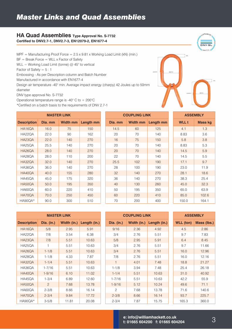
HA Quad Assemblies Type Approval No. S-7732Certified to DNV2.7-1, DNV2.7-3, EN12079-2, EN1677-4
MPF = Manufacturing Proof Force = 2.5 x 9.81 x Working Load Limit (kN) (min.)BF = Break Force = WLL x Factor of SafetyWLL = Working Load Limit (tonne) @ 45° to verticalFactor of Safety = 5 : 1Embossing - As per Description column and Batch NumberManufactured in accordance with EN1677-4Design air temperature -40° min. Average impact energy (charpy) 42 Joules up to 50mm diameterDNV type approval No. S-7732Operational temperature range is -40° C to + 200°C*Certified on a batch basis to the requirements of DNV 2.7-1
MASTER LINK
Description Dia. mm Width mm Length mm
HA16QA 16.0 75 150
HA22QA 22.0 90 162
HA23QA 22.0 140 270
HA25QA 25.5 140 270
HA26QA 28.0 140 270
HA28QA 28.0 110 200
HA32QA 32.0 140 270
HA36QA 36.0 140 270
HA40QA 40.0 155 280
HA45QA 45.0 175 320
HA50QA 50.0 195 350
HA60QA 60.0 220 410
HA70QA 70.0 250 450
HA90QA* 90.0 300 510
COUPLING LINK
Dia. mm Width mm Length mm
14.5 60 125
20 70 140
16 75 150
20 70 140
20 70 140
22 70 140
25.5 102 190
28 100 190
32 140 270
36 140 270
40 130 260
50 195 350
60 220 410
70 200 400
ASSEMBLY
WLL t Mass kg
4.1 1.3
8.83 3.6
5.8 3.8
8.83 5.3
14.5 5.9
14.5 5.5
17.1 9.7
23.0 11.9
28.1 18.6
38.3 25.4
45.0 32.3
65.0 63.9
85.0 102.6
150.0 164.1
MASTER LINK
Description Dia. (in.) Width (in.) Length (in.)
HA16QA 5/8 2.95 5.91
HA22QA 7/8 3.54 6.38
HA23QA 7/8 5.51 10.63
HA25QA 1 5.51 10.63
HA26QA 1-1/8 5.51 10.63
HA28QA 1-1/8 4.33 7.87
HA32QA 1-1/4 5.51 10.63
HA36QA 1-7/16 5.51 10.63
HA40QA 1-9/16 6.10 11.02
HA45QA 1-3/4 6.89 12.60
HA50QA 2 7.68 13.78
HA60QA 2-3/8 8.66 16.14
HA70QA 2-3/4 9.84 17.72
HA90QA* 3-5/8 11.81 20.08
COUPLING LINK
Dia. (in.) Width (in.) Length (in.)
9/16 2.36 4.92
3/4 2.76 5.51
5/8 2.95 5.91
3/4 2.76 5.51
3/4 2.76 5.51
7/8 2.76 5.51
1 4.01 7.48
1-1/8 3.94 7.48
1-1/4 5.51 10.63
1-7/16 5.51 10.63
1-9/16 5.12 10.24
2 7.68 13.78
2-3/8 8.66 16.14
2-3/4 7.87 15.75
ASSEMBLY
WLL (ton) Mass (lbs.)
4.5 2.86
9.7 7.83
6.4 8.45
9.7 11.66
16.0 12.96
16.0 12.16
18.8 21.27
25.4 26.18
31.0 40.92
42.2 55.9
49.6 71.1
71.6 140.6
93.7 225.7
165.3 360.0
LENGTH
WIDTH
DIA.
WIDTH
DIA.
LENGTH WIDTH
DIA.
LENGTH
Welded Chain Slings
Part Code Description Working Load Limit 10ft ContainerLeg Length
20ft ContainerLeg Length
30° 45° 30° 45° 30° 45°
W13.4.DNV 13mm x 4 Leg 13.5t 11.2t 3.8m 2.7m 6.5m 4.6m
W13.5.DNV 13mm x 5 Leg 13.5t 11.2t 3.8m 2.7m 6.5m 4.6m
W16.4.DNV 16mm x 4 Leg 20.5t 16.5t 3.8m 2.7m 6.5m 4.6m
W16.5.DNV 16mm x 5 Leg 20.5t 16.5t 3.8m 2.7m 6.5m 4.6m
W20.4.DNV 20mm x 4 Leg 32.0t 26.0t 3.8m 2.7m 6.5m 4.6m
W20.5.DNV 20mm x 5 Leg 32.0t 26.0t 3.8m 2.7m 6.5m 4.6m
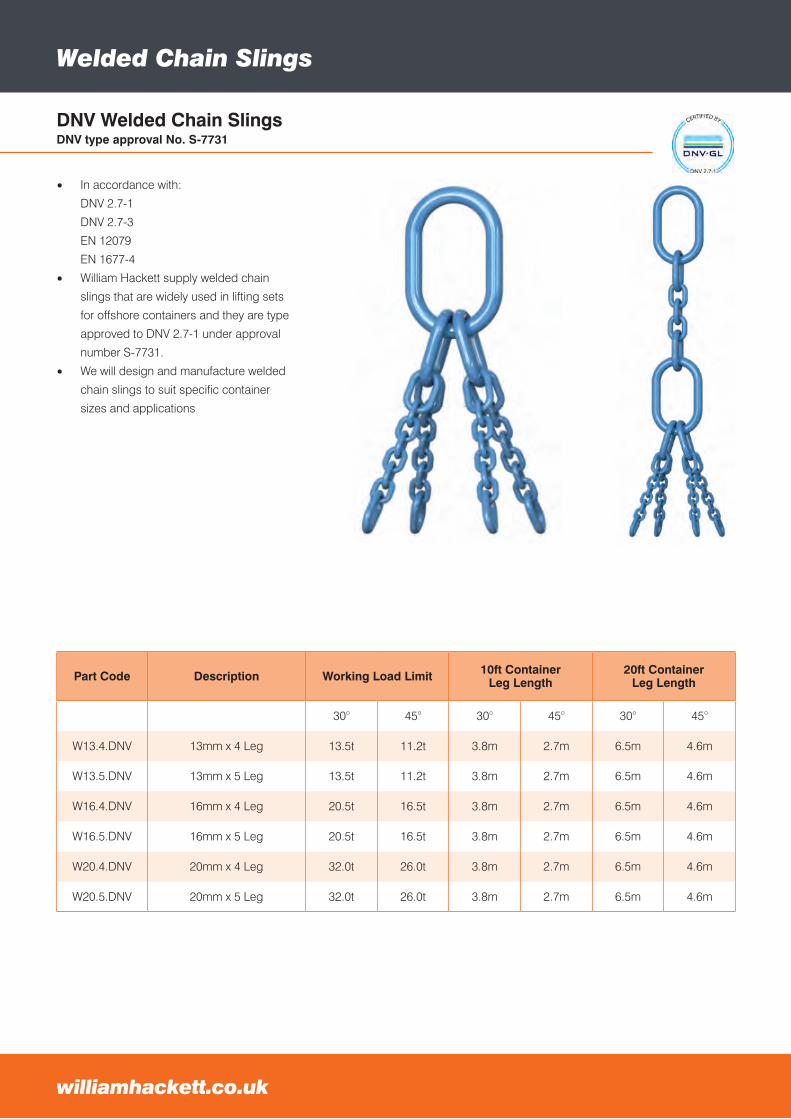
DNV Welded Chain SlingsDNV type approval No. S-7731
• In accordance with:
DNV 2.7-1
DNV 2.7-3
EN 12079
EN 1677-4
• William Hackett supply welded chain
slings that are widely used in lifting sets
for offshore containers and they are type
approved to DNV 2.7-1 under approval
number S-7731.
• We will design and manufacture welded
chain slings to suit specific container
sizes and applications
e: [email protected]: 01665 604200 f: 01665 604204williamhackett.co.uk
Welded Chain Slings
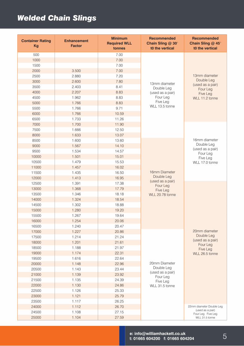
Container RatingKg
EnhancementFactor
MinimumRequired WLL
tonnes
RecommendedChain Sling @ 30°
t0 the vertical
RecommendedChain Sling @ 45°
t0 the vertical
500 7.00
13mm diameterDouble Leg
(used as a pair)Four LegFive Leg
WLL 13.5 tonne
13mm diameterDouble Leg
(used as a pair)Four LegFive Leg
WLL 11.2 tonne
1000 7.001500 7.002000 3.500 7.002500 2.880 7.203000 2.600 7.803500 2.403 8.414000 2.207 8.834500 1.962 8.835000 1.766 8.835500 1.766 9.716000 1.766 10.596500 1.733 11.267000 1.700 11.90
16mm diameterDouble Leg
(used as a pair)Four LegFive Leg
WLL 17.0 tonne
7500 1.666 12.508000 1.633 13.078500 1.600 13.60
16mm DiameterDouble Leg
(used as a pair)Four LegFive Leg
WLL 20.78 tonne
9000 1.567 14.109500 1.534 14.5710000 1.501 15.0110500 1.479 15.5311000 1.457 16.0211500 1.435 16.5012000 1.413 16.9512500 1.391 17.38
20mm diameterDouble Leg
(used as a pair)Four LegFive Leg
WLL 26.5 tonne
13000 1.368 17.7913500 1.346 18.1814000 1.324 18.5414500 1.302 18.8815000 1.280 19.2015500 1.267 19.6416000 1.254 20.0616500 1.240 20.4717000 1.227 20.86
20mm DiameterDouble Leg
(used as a pair)Four LegFive Leg
WLL 31.5 tonne
17500 1.214 21.2418000 1.201 21.6118500 1.188 21.9719000 1.174 22.3119500 1.616 22.6420000 1.148 22.9620500 1.143 23.4421000 1.139 23.9221500 1.135 24.3922000 1.130 24.8622500 1.126 25.3323000 1.121 25.7923500 1.117 26.2524000 1.112 26.70 22mm diameter Double Leg
(used as a pair)Four Leg Five Leg
WLL 31.5 tonne
24500 1.108 27.1525000 1.104 27.59
5e: [email protected]: 01665 604200 f: 01665 604204
DNV Type Approved Shackles
williamhackett.co.uk
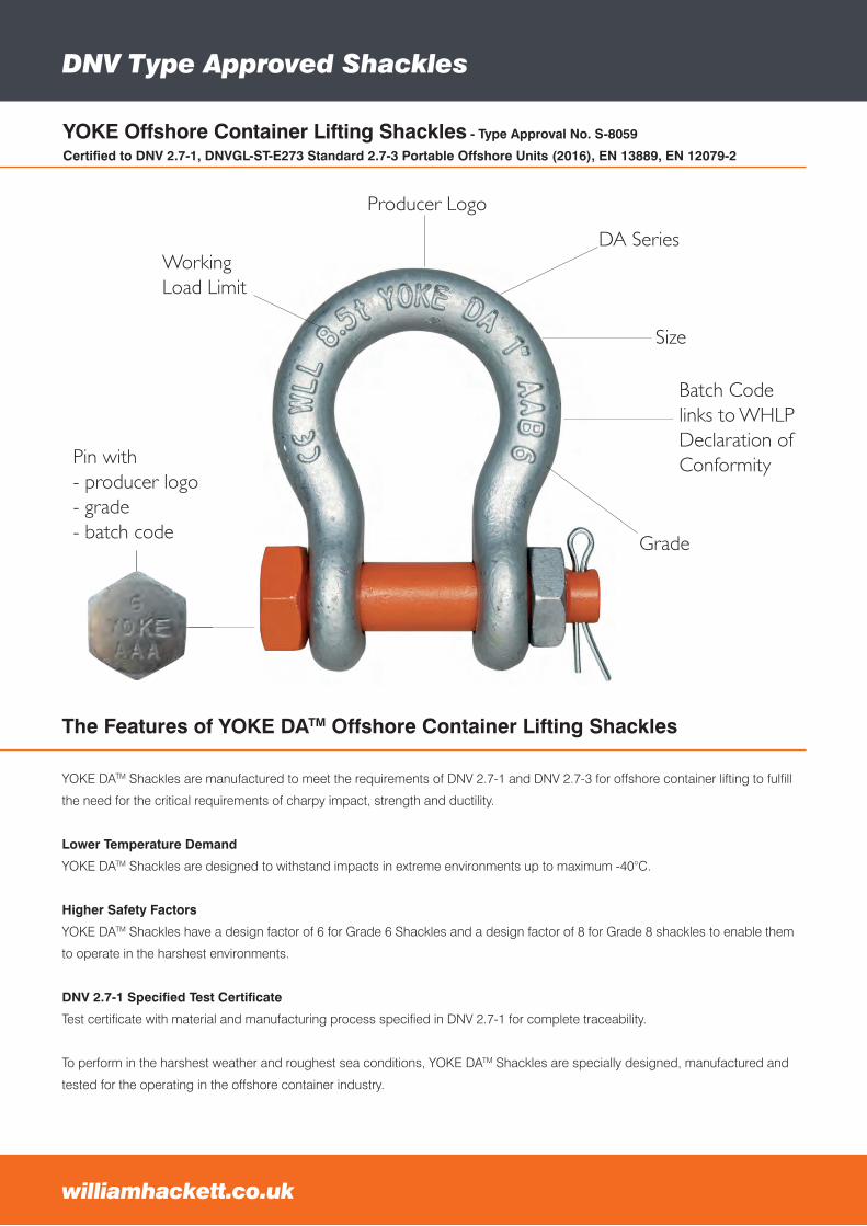
YOKE Offshore Container Lifting Shackles - Type Approval No. S-8059
Certified to DNV 2.7-1, DNVGL-ST-E273 Standard 2.7-3 Portable Offshore Units (2016), EN 13889, EN 12079-2
YOKE DATM Shackles are manufactured to meet the requirements of DNV 2.7-1 and DNV 2.7-3 for offshore container lifting to fulfill
the need for the critical requirements of charpy impact, strength and ductility.
Lower Temperature Demand
YOKE DATM Shackles are designed to withstand impacts in extreme environments up to maximum -40°C.
Higher Safety Factors
YOKE DATM Shackles have a design factor of 6 for Grade 6 Shackles and a design factor of 8 for Grade 8 shackles to enable them
to operate in the harshest environments.
DNV 2.7-1 Specified Test Certificate
Test certificate with material and manufacturing process specified in DNV 2.7-1 for complete traceability.
To perform in the harshest weather and roughest sea conditions, YOKE DATM Shackles are specially designed, manufactured and
tested for the operating in the offshore container industry.
The Features of YOKE DATM Offshore Container Lifting Shackles
NEVER EXCEED PUBLISHED WORKING LOAD LIMIT
WARNINGCopyright © 2015
YOKE Industrial Corp.All Rights Reserved.
YOKE Offshore Container Lifting Shackles
DNV 2.7-1 Type Approved
Producer logo
Grade
Size
Batch Code links to Test Certification sheet
DA Series
Working Load Limit
Pin with - producer logo - grade - batch code
12
Working Load Limit
Producer Logo
DA Series
Size
Grade
Batch Codelinks to WHLPDeclaration ofConformityPin with
- producer logo- grade- batch code
DNV Type Approved Shackles
7e: [email protected]: 01665 604200 f: 01665 604204
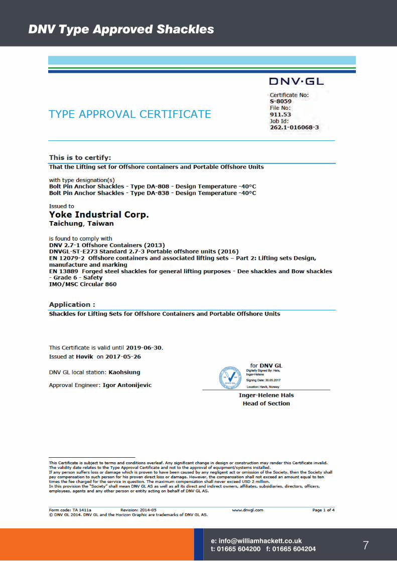
Form code: TA 1411a Revision: 2014-05 www.dnvgl.com Page 1 of 4 © DNV GL 2014. DNV GL and the Horizon Graphic are trademarks of DNV GL AS.
TYPE APPROVAL CERTIFICATE
Certificate No: S-8059 File No: 911.53 Job Id: 262.1-016068-3
This is to certify: That the Lifting set for Offshore containers and Portable Offshore Units with type designation(s) Bolt Pin Anchor Shackles - Type DA-808 - Design Temperature -40°C Bolt Pin Anchor Shackles - Type DA-838 - Design Temperature -40°C Issued to
Yoke Industrial Corp. Taichung, Taiwan is found to comply with DNV 2.7-1 Offshore Containers (2013) DNVGL-ST-E273 Standard 2.7-3 Portable offshore units (2016) EN 12079-2 Offshore containers and associated lifting sets – Part 2: Lifting sets Design, manufacture and marking EN 13889 Forged steel shackles for general lifting purposes - Dee shackles and Bow shackles - Grade 6 - Safety IMO/MSC Circular 860 Application : Shackles for Lifting Sets for Offshore Containers and Portable Offshore Units
This Certificate is valid until 2019-06-30. Issued at Høvik on 2017-05-26
DNV GL local station: Kaohsiung Approval Engineer: Igor Antonijevic
for DNV GL
Inger-Helene Hals
Head of Section
This Certificate is subject to terms and conditions overleaf. Any significant change in design or construction may render this Certificate invalid. The validity date relates to the Type Approval Certificate and not to the approval of equipment/systems installed. If any person suffers loss or damage which is proven to have been caused by any negligent act or omission of the Society, then the Society shall pay compensation to such person for his proven direct loss or damage. However, the compensation shall not exceed an amount equal to ten times the fee charged for the service in question. The maximum compensation shall never exceed USD 2 million. In this provision the “Society” shall mean DNV GL AS as well as all its direct and indirect owners, affiliates, subsidiaries, directors, officers, employees, agents and any other person or entity acting on behalf of DNV GL AS.
DNV Type Approved Shackles
PartCode
Sizemm
WLLtonnes*
Amm
Bmm
Dmm
Emm
Gmm
Hmm
Wmm
MassKg
DA-838-13 13 2.00 47 13 16 33 30 85 20 0.4DA-838-16 16 3.25 61 16 19 43 38 106 27 0.7DA-838-19 19 4.75 72 19 22 50 46 126 33 1.0DA-838-22 22 6.50 86 22 26 58 53 148 38 1.7DA-838-26 26 8.50 96 26 28 68 61 166 44 2.4DA-838-28 28 9.50 111 28 32 74 68 190 46 3.4DA-838-32 32 12.00 121 32 36 84 76 210 54 4.8DA-838-36 36 13.50 134 36 38 92 84 232 59 6.5DA-838-38 38 17.00 146 38 45 99 92 254 60 8.8DA-838-45 45 25.00 178 47 51 127 106 313 73 17.5DA-838-50 50 35.00 197 53 57 146 122 347 83 24.2DA-838-64 64 **55.00 267 66.5 70 184 145 453 105 43.5DA-838-76 76 **85.00 330 76 82.5 200 165 546 127 81DA-838-89 89 **120.00 372 92 95.5 229 203 626 133 120
DA-838-100 100 **150.00 368 104 108 254 229 653 140 153
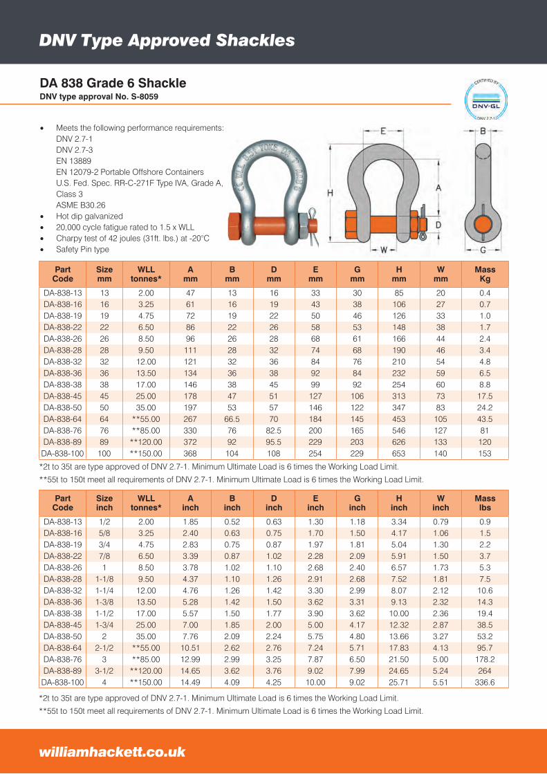
• Meets the following performance requirements:DNV 2.7-1DNV 2.7-3EN 13889EN 12079-2 Portable Offshore Containers U.S. Fed. Spec. RR-C-271F Type IVA, Grade A, Class 3 ASME B30.26
• Hot dip galvanized• 20,000 cycle fatigue rated to 1.5 x WLL• Charpy test of 42 joules (31ft. lbs.) at -20°C• Safety Pin type
DA 838 Grade 6 ShackleDNV type approval No. S-8059
*2t to 35t are type approved of DNV 2.7-1. Minimum Ultimate Load is 6 times the Working Load Limit.
**55t to 150t meet all requirements of DNV 2.7-1. Minimum Ultimate Load is 6 times the Working Load Limit.
williamhackett.co.uk
PartCode
Sizeinch
WLLtonnes*
Ainch
Binch
Dinch
Einch
Ginch
Hinch
Winch
Masslbs
DA-838-13 1/2 2.00 1.85 0.52 0.63 1.30 1.18 3.34 0.79 0.9DA-838-16 5/8 3.25 2.40 0.63 0.75 1.70 1.50 4.17 1.06 1.5DA-838-19 3/4 4.75 2.83 0.75 0.87 1.97 1.81 5.04 1.30 2.2DA-838-22 7/8 6.50 3.39 0.87 1.02 2.28 2.09 5.91 1.50 3.7DA-838-26 1 8.50 3.78 1.02 1.10 2.68 2.40 6.57 1.73 5.3DA-838-28 1-1/8 9.50 4.37 1.10 1.26 2.91 2.68 7.52 1.81 7.5DA-838-32 1-1/4 12.00 4.76 1.26 1.42 3.30 2.99 8.07 2.12 10.6DA-838-36 1-3/8 13.50 5.28 1.42 1.50 3.62 3.31 9.13 2.32 14.3DA-838-38 1-1/2 17.00 5.57 1.50 1.77 3.90 3.62 10.00 2.36 19.4DA-838-45 1-3/4 25.00 7.00 1.85 2.00 5.00 4.17 12.32 2.87 38.5DA-838-50 2 35.00 7.76 2.09 2.24 5.75 4.80 13.66 3.27 53.2DA-838-64 2-1/2 **55.00 10.51 2.62 2.76 7.24 5.71 17.83 4.13 95.7DA-838-76 3 **85.00 12.99 2.99 3.25 7.87 6.50 21.50 5.00 178.2DA-838-89 3-1/2 **120.00 14.65 3.62 3.76 9.02 7.99 24.65 5.24 264
DA-838-100 4 **150.00 14.49 4.09 4.25 10.00 9.02 25.71 5.51 336.6
*2t to 35t are type approved of DNV 2.7-1. Minimum Ultimate Load is 6 times the Working Load Limit.
**55t to 150t meet all requirements of DNV 2.7-1. Minimum Ultimate Load is 6 times the Working Load Limit.
DNV Type Approved Shackles
9e: [email protected]: 01665 604200 f: 01665 604204
PartCode
Sizemm
WLLtonnes*
Amm
Bmm
Dmm
Emm
Gmm
Hmm
Wmm
MassKg
DA-808-13 13 2.00 47 13 16 33 30 85 20 0.4DA-808-16 16 3.25 61 16 19 43 38 106 27 0.7DA-808-19 19 4.75 72 19 22 50 46 126 33 1.0DA-808-22 22 6.50 86 22 26 58 53 148 38 1.7DA-808-26 26 8.50 96 26 28 68 61 166 44 2.4DA-808-28 28 9.50 111 28 32 74 68 190 46 3.4DA-808-32 32 12.00 121 32 36 84 76 210 54 4.8DA-808-36 36 13.50 134 36 38 92 84 232 59 6.5DA-808-38 38 17.00 146 38 45 99 92 254 60 8.8DA-808-45 45 25.00 178 47 51 127 106 313 73 17.5DA-808-50 50 35.00 197 53 57 146 122 347 83 24.2DA-808-64 64 **85.00 267 66.5 70 184 145 453 105 43.5DA-808-76 76 **120.00 330 76 82.5 200 165 546 127 81DA-808-89 89 **150.00 372 92 95.5 229 203 626 133 120
DA-808-100 100 **175.00 368 104 108 254 229 653 140 153
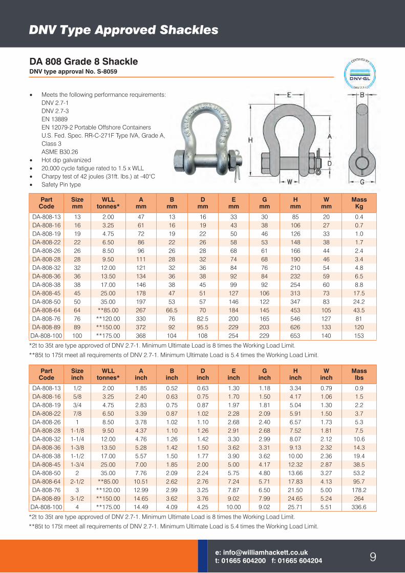
• Meets the following performance requirements:DNV 2.7-1DNV 2.7-3EN 13889EN 12079-2 Portable Offshore Containers U.S. Fed. Spec. RR-C-271F Type IVA, Grade A, Class 3 ASME B30.26
• Hot dip galvanized• 20,000 cycle fatigue rated to 1.5 x WLL• Charpy test of 42 joules (31ft. lbs.) at -40°C• Safety Pin type
DA 808 Grade 8 ShackleDNV type approval No. S-8059
*2t to 35t are type approved of DNV 2.7-1. Minimum Ultimate Load is 8 times the Working Load Limit.
**85t to 175t meet all requirements of DNV 2.7-1. Minimum Ultimate Load is 5.4 times the Working Load Limit.
PartCode
Sizeinch
WLLtonnes*
Ainch
Binch
Dinch
Einch
Ginch
Hinch
Winch
Masslbs
DA-808-13 1/2 2.00 1.85 0.52 0.63 1.30 1.18 3.34 0.79 0.9DA-808-16 5/8 3.25 2.40 0.63 0.75 1.70 1.50 4.17 1.06 1.5DA-808-19 3/4 4.75 2.83 0.75 0.87 1.97 1.81 5.04 1.30 2.2DA-808-22 7/8 6.50 3.39 0.87 1.02 2.28 2.09 5.91 1.50 3.7DA-808-26 1 8.50 3.78 1.02 1.10 2.68 2.40 6.57 1.73 5.3DA-808-28 1-1/8 9.50 4.37 1.10 1.26 2.91 2.68 7.52 1.81 7.5DA-808-32 1-1/4 12.00 4.76 1.26 1.42 3.30 2.99 8.07 2.12 10.6DA-808-36 1-3/8 13.50 5.28 1.42 1.50 3.62 3.31 9.13 2.32 14.3DA-808-38 1-1/2 17.00 5.57 1.50 1.77 3.90 3.62 10.00 2.36 19.4DA-808-45 1-3/4 25.00 7.00 1.85 2.00 5.00 4.17 12.32 2.87 38.5DA-808-50 2 35.00 7.76 2.09 2.24 5.75 4.80 13.66 3.27 53.2DA-808-64 2-1/2 **85.00 10.51 2.62 2.76 7.24 5.71 17.83 4.13 95.7DA-808-76 3 **120.00 12.99 2.99 3.25 7.87 6.50 21.50 5.00 178.2DA-808-89 3-1/2 **150.00 14.65 3.62 3.76 9.02 7.99 24.65 5.24 264
DA-808-100 4 **175.00 14.49 4.09 4.25 10.00 9.02 25.71 5.51 336.6
*2t to 35t are type approved of DNV 2.7-1. Minimum Ultimate Load is 8 times the Working Load Limit.
**85t to 175t meet all requirements of DNV 2.7-1. Minimum Ultimate Load is 5.4 times the Working Load Limit.
williamhackett.co.uk
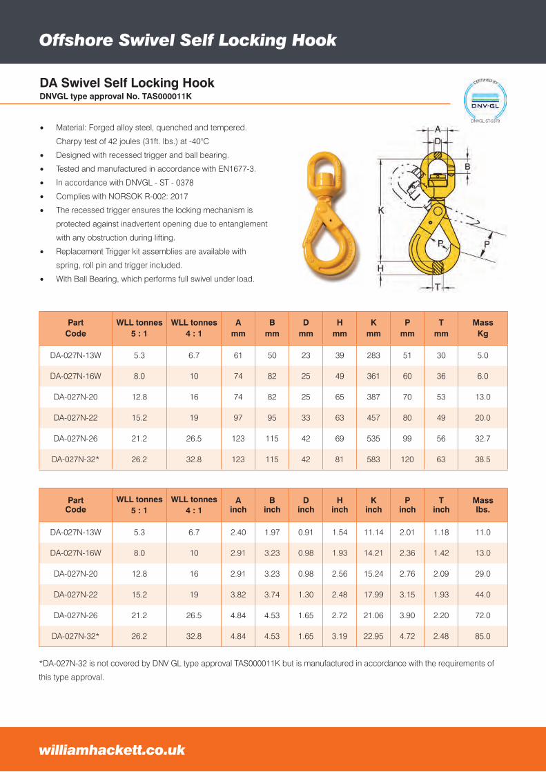
Offshore Swivel Self Locking Hook
PartCode
WLL tonnes5 : 1
WLL tonnes4 : 1
Ainch
Binch
Dinch
Hinch
Kinch
Pinch
Tinch
Masslbs.
DA-027N-13W 5.3 6.7 2.40 1.97 0.91 1.54 11.14 2.01 1.18 11.0
DA-027N-16W 8.0 10 2.91 3.23 0.98 1.93 14.21 2.36 1.42 13.0
DA-027N-20 12.8 16 2.91 3.23 0.98 2.56 15.24 2.76 2.09 29.0
DA-027N-22 15.2 19 3.82 3.74 1.30 2.48 17.99 3.15 1.93 44.0
DA-027N-26 21.2 26.5 4.84 4.53 1.65 2.72 21.06 3.90 2.20 72.0
DA-027N-32* 26.2 32.8 4.84 4.53 1.65 3.19 22.95 4.72 2.48 85.0
• Material: Forged alloy steel, quenched and tempered.
Charpy test of 42 joules (31ft. lbs.) at -40°C
• Designed with recessed trigger and ball bearing.
• Tested and manufactured in accordance with EN1677-3.
• In accordance with DNVGL - ST - 0378
• Complies with NORSOK R-002: 2017
• The recessed trigger ensures the locking mechanism is
protected against inadvertent opening due to entanglement
with any obstruction during lifting.
• Replacement Trigger kit assemblies are available with
spring, roll pin and trigger included.
• With Ball Bearing, which performs full swivel under load.
DA Swivel Self Locking HookDNVGL type approval No. TAS000011K
PartCode
WLL tonnes5 : 1
WLL tonnes4 : 1
Amm
Bmm
Dmm
Hmm
Kmm
Pmm
Tmm
MassKg
DA-027N-13W 5.3 6.7 61 50 23 39 283 51 30 5.0
DA-027N-16W 8.0 10 74 82 25 49 361 60 36 6.0
DA-027N-20 12.8 16 74 82 25 65 387 70 53 13.0
DA-027N-22 15.2 19 97 95 33 63 457 80 49 20.0
DA-027N-26 21.2 26.5 123 115 42 69 535 99 56 32.7
DA-027N-32* 26.2 32.8 123 115 42 81 583 120 63 38.5
*DA-027N-32 is not covered by DNV GL type approval TAS000011K but is manufactured in accordance with the requirements of
this type approval.
DNVGL ST-0378
ROV Corrosion Chain Hoist
11e: [email protected]: 01665 604200 f: 01665 604204
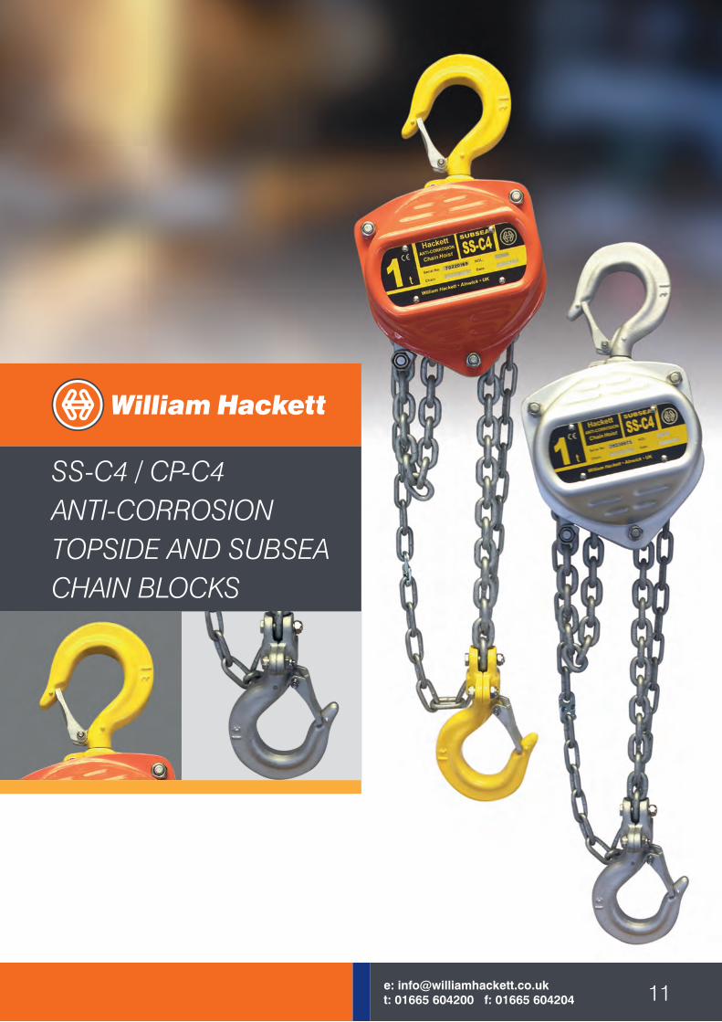
SS-C4 / CP-C4ANTI-CORROSIONTOPSIDE AND SUBSEACHAIN BLOCKS
williamhackett.co.uk
Anti-Corrosion
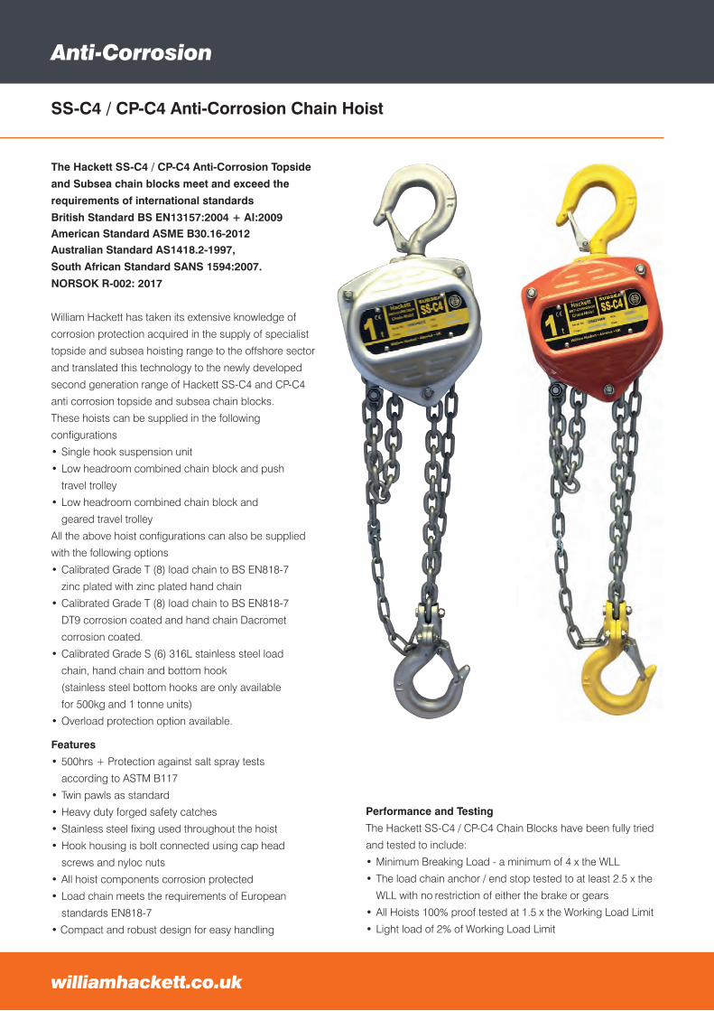
The Hackett SS-C4 / CP-C4 Anti-Corrosion Topside
and Subsea chain blocks meet and exceed the
requirements of international standards
British Standard BS EN13157:2004 + AI:2009American Standard ASME B30.16-2012 Australian Standard AS1418.2-1997,
South African Standard SANS 1594:2007.
NORSOK R-002: 2017
William Hackett has taken its extensive knowledge of
corrosion protection acquired in the supply of specialist
topside and subsea hoisting range to the offshore sector
and translated this technology to the newly developed
second generation range of Hackett SS-C4 and CP-C4
anti corrosion topside and subsea chain blocks.
These hoists can be supplied in the following
configurations
• Single hook suspension unit
• Low headroom combined chain block and push
travel trolley
• Low headroom combined chain block and
geared travel trolley
All the above hoist configurations can also be supplied
with the following options
• Calibrated Grade T (8) load chain to BS EN818-7
zinc plated with zinc plated hand chain
• Calibrated Grade T (8) load chain to BS EN818-7
DT9 corrosion coated and hand chain Dacromet
corrosion coated.
• Calibrated Grade S (6) 316L stainless steel load
chain, hand chain and bottom hook
(stainless steel bottom hooks are only available
for 500kg and 1 tonne units)
• Overload protection option available.
Features
• 500hrs + Protection against salt spray tests
according to ASTM B117
• Twin pawls as standard
• Heavy duty forged safety catches
• Stainless steel fixing used throughout the hoist
• Hook housing is bolt connected using cap head
screws and nyloc nuts
• All hoist components corrosion protected
• Load chain meets the requirements of European
standards EN818-7
• Compact and robust design for easy handling
SS-C4 / CP-C4 Anti-Corrosion Chain Hoist
Performance and Testing
The Hackett SS-C4 / CP-C4 Chain Blocks have been fully tried
and tested to include:
• Minimum Breaking Load - a minimum of 4 x the WLL
• The load chain anchor / end stop tested to at least 2.5 x the
WLL with no restriction of either the brake or gears
• All Hoists 100% proof tested at 1.5 x the Working Load Limit
• Light load of 2% of Working Load Limit
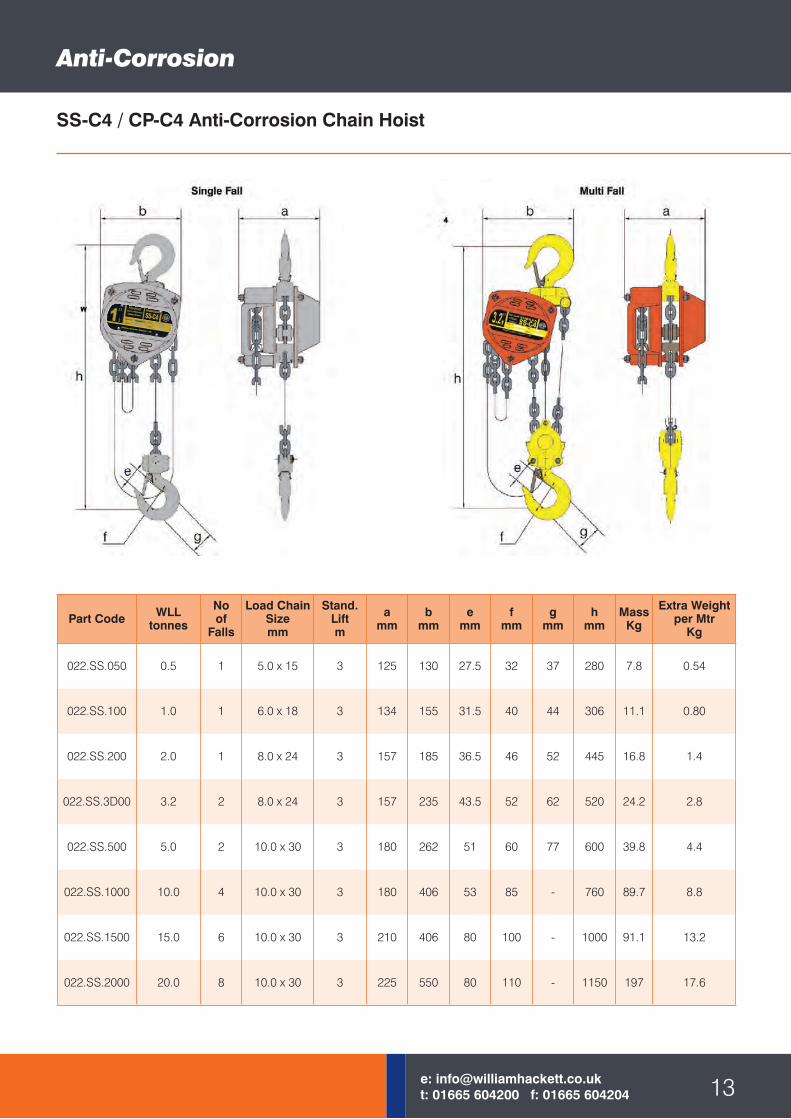
Part Code WLLtonnes
Noof
Falls
Load ChainSizemm
Stand.Liftm
amm
bmm
emm
fmm
gmm
hmm
MassKg
Extra Weightper Mtr
Kg
022.SS.050 0.5 1 5.0 x 15 3 125 130 27.5 32 37 280 7.8 0.54
022.SS.100 1.0 1 6.0 x 18 3 134 155 31.5 40 44 306 11.1 0.80
022.SS.200 2.0 1 8.0 x 24 3 157 185 36.5 46 52 445 16.8 1.4
022.SS.3D00 3.2 2 8.0 x 24 3 157 235 43.5 52 62 520 24.2 2.8
022.SS.500 5.0 2 10.0 x 30 3 180 262 51 60 77 600 39.8 4.4
022.SS.1000 10.0 4 10.0 x 30 3 180 406 53 85 - 760 89.7 8.8
022.SS.1500 15.0 6 10.0 x 30 3 210 406 80 100 - 1000 91.1 13.2
022.SS.2000 20.0 8 10.0 x 30 3 225 550 80 110 - 1150 197 17.6
Anti-Corrosion
13e: [email protected]: 01665 604200 f: 01665 604204
SS-C4 / CP-C4 Anti-Corrosion Chain Hoist
williamhackett.co.uk
Anti-Corrosion
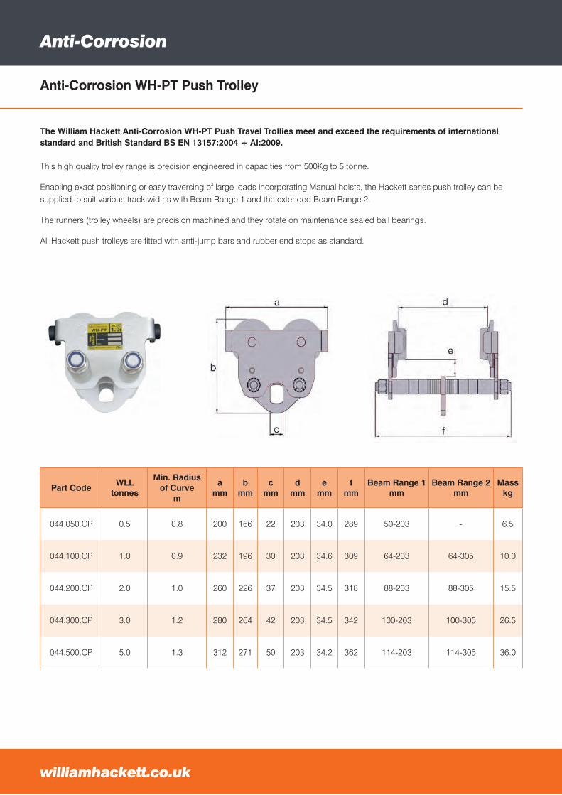
The William Hackett Anti-Corrosion WH-PT Push Travel Trollies meet and exceed the requirements of international standard and British Standard BS EN 13157:2004 + AI:2009.
This high quality trolley range is precision engineered in capacities from 500Kg to 5 tonne.
Enabling exact positioning or easy traversing of large loads incorporating Manual hoists, the Hackett series push trolley can be supplied to suit various track widths with Beam Range 1 and the extended Beam Range 2.
The runners (trolley wheels) are precision machined and they rotate on maintenance sealed ball bearings.
All Hackett push trolleys are fitted with anti-jump bars and rubber end stops as standard.
Anti-Corrosion WH-PT Push Trolley
williamhackett.co.uk
Part CodeWLL
tonnes
Min. Radiusof Curve
m
amm
bmm
cmm
dmm
emm
fmm
Beam Range 1 mm
Beam Range 2 mm
Mass kg
044.050.CP 0.5 0.8 200 166 22 203 34.0 289 50-203 - 6.5
044.100.CP 1.0 0.9 232 196 30 203 34.6 309 64-203 64-305 10.0
044.200.CP 2.0 1.0 260 226 37 203 34.5 318 88-203 88-305 15.5
044.300.CP 3.0 1.2 280 264 42 203 34.5 342 100-203 100-305 26.5
044.500.CP 5.0 1.3 312 271 50 203 34.2 362 114-203 114-305 36.0
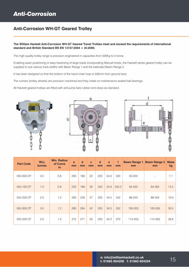
Anti-Corrosion WH-GT Geared Trolley
Part CodeWLL
tonnes
Min. Radiusof Curve
m
amm
bmm
cmm
dmm
emm
fmm
Beam Range 1 mm
Beam Range 2 mm
Mass kg
055.050.CP 0.5 0.8 200 166 22 203 34.0 320 50-203 - 7.1
055.100.CP 1.0 0.9 232 196 30 203 34.6 333.2 64-203 64-305 13.5
055.200.CP 2.0 1.0 260 226 37 203 34.5 342 88-203 88-305 19.0
055.300.CP 3.0 1.2 280 264 42 203 34.5 352 100-203 100-305 30.5
055.500.CP 5.0 1.3 312 271 50 203 34.2 370 114-203 114-305 38.6
Anti-Corrosion
The William Hackett Anti-Corrosion WH-GT Geared Travel Trollies meet and exceed the requirements of international standard and British Standard BS EN 13157:2004 + AI:2009.
This high quality trolley range is precision engineered in capacities from 500Kg to 5 tonne.
Enabling exact positioning or easy traversing of large loads incorporating Manual hoists, the Hackett series geared trolley can be supplied to suit various track widths with Beam Range 1 and the extended Beam Range 2.
It has been designed so that the bottom of the hand chain loop is 500mm from ground level.
The runners (trolley wheels) are precision machined and they rotate on maintenance sealed ball bearings.
All Hackett geared trolleys are fitted with anti-jump bars rubber end stops as standard.
15e: [email protected]: 01665 604200 f: 01665 604204
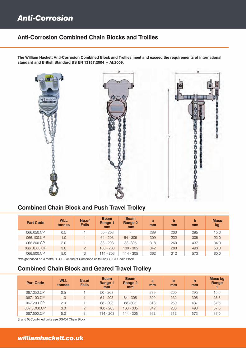
Combined Chain Block and Geared Travel Trolley
*Weight based on 3 metre H.O.L. 3t and 5t Combined units use SS-C4 Chain Block
Part Code WLLtonnes
No.ofFalls
BeamRange 1
mm
BeamRange 2
mm
amm
bmm
hmm
Masskg
066.050.CP 0.5 1 50 - 203 - 289 200 295 15.0066.100.CP 1.0 1 64 - 203 64 - 305 309 232 305 22.0066.200.CP 2.0 1 88 - 203 88 -305 318 260 437 34.0
066.3D00.CP 3.0 2 100 - 203 100 - 305 342 280 493 53.0066.500.CP 5.0 3 114 - 203 114 - 305 362 312 573 80.0
Part Code WLLtonnes
No.ofFalls
BeamRange 1
mm
BeamRange 2
mm
amm
bmm
hmm
Mass kgRange
1067.050.CP 0.5 1 50 - 203 - 289 200 295 15.6067.100.CP 1.0 1 64 - 203 64 - 305 309 232 305 25.5067.200.CP 2.0 1 88 - 203 88 -305 318 260 437 37.5
067.3D00.CP 3.0 2 100 - 203 100 - 305 342 280 493 57.0067.500.CP 5.0 3 114 - 203 114 - 305 362 312 573 83.0
Combined Chain Block and Push Travel Trolley
Anti-Corrosion
The William Hackett Anti-Corrosion Combined Block and Trollies meet and exceed the requirements of international standard and British Standard BS EN 13157:2004 + AI:2009.
Anti-Corrosion Combined Chain Blocks and Trollies
williamhackett.co.ukwilliamhackett.co.uk
3t and 5t Combined units use SS-C4 Chain Block
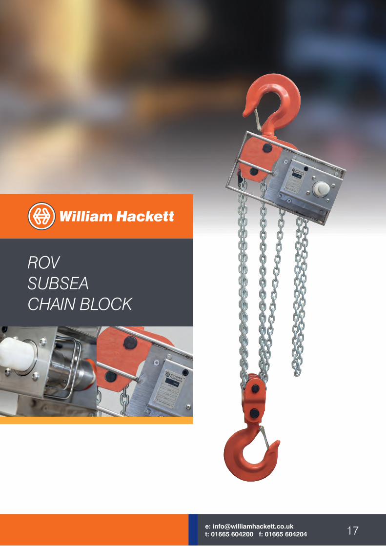
ROVSUBSEACHAIN BLOCK
17e: [email protected]: 01665 604200 f: 01665 604204 17e: [email protected]: 01665 604200 f: 01665 604204
ROV Subsea Chain Block
williamhackett.co.uk
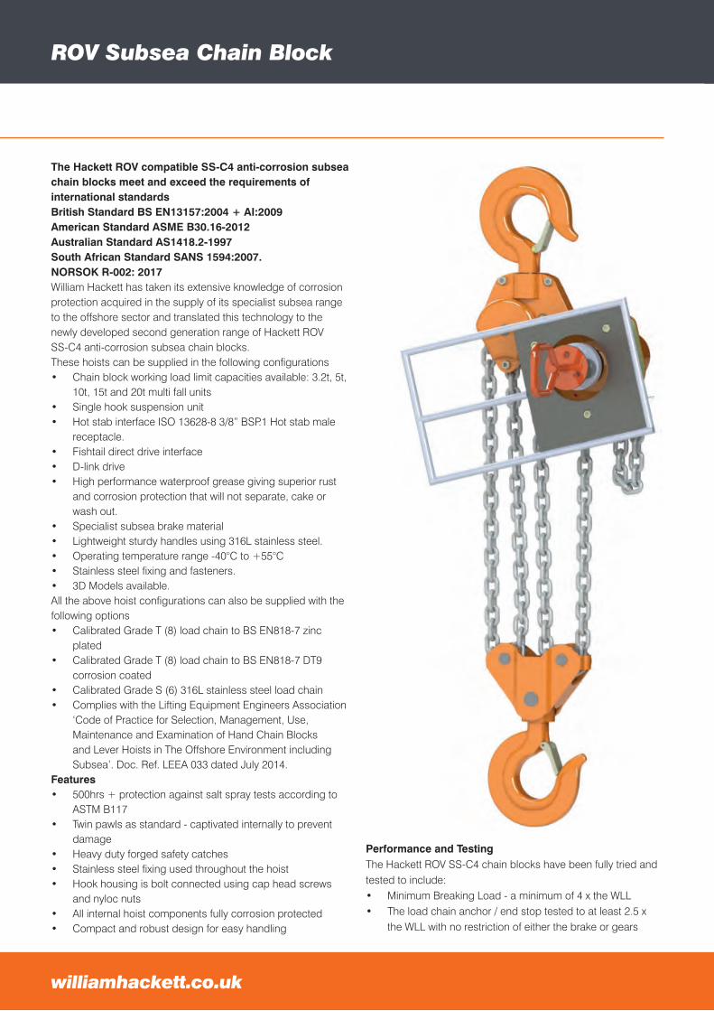
The Hackett ROV compatible SS-C4 anti-corrosion subsea chain blocks meet and exceed the requirements of international standardsBritish Standard BS EN13157:2004 + AI:2009American Standard ASME B30.16-2012Australian Standard AS1418.2-1997South African Standard SANS 1594:2007.NORSOK R-002: 2017William Hackett has taken its extensive knowledge of corrosion protection acquired in the supply of its specialist subsea range to the offshore sector and translated this technology to the newly developed second generation range of Hackett ROVSS-C4 anti-corrosion subsea chain blocks.These hoists can be supplied in the following configurations• Chain block working load limit capacities available: 3.2t, 5t,
10t, 15t and 20t multi fall units• Single hook suspension unit• Hot stab interface ISO 13628-8 3/8” BSP.1 Hot stab male
receptacle.• Fishtail direct drive interface• D-link drive• High performance waterproof grease giving superior rust
and corrosion protection that will not separate, cake or wash out.
• Specialist subsea brake material• Lightweight sturdy handles using 316L stainless steel.• Operating temperature range -40°C to +55°C• Stainless steel fixing and fasteners.• 3D Models available.All the above hoist configurations can also be supplied with the following options• Calibrated Grade T (8) load chain to BS EN818-7 zinc
plated• Calibrated Grade T (8) load chain to BS EN818-7 DT9
corrosion coated• Calibrated Grade S (6) 316L stainless steel load chain• Complies with the Lifting Equipment Engineers Association
‘Code of Practice for Selection, Management, Use, Maintenance and Examination of Hand Chain Blocks and Lever Hoists in The Offshore Environment including Subsea’. Doc. Ref. LEEA 033 dated July 2014.
Features• 500hrs + protection against salt spray tests according to
ASTM B117• Twin pawls as standard - captivated internally to prevent
damage• Heavy duty forged safety catches• Stainless steel fixing used throughout the hoist• Hook housing is bolt connected using cap head screws
and nyloc nuts• All internal hoist components fully corrosion protected• Compact and robust design for easy handling
Performance and TestingThe Hackett ROV SS-C4 chain blocks have been fully tried and tested to include:• Minimum Breaking Load - a minimum of 4 x the WLL• The load chain anchor / end stop tested to at least 2.5 x
the WLL with no restriction of either the brake or gears
williamhackett.co.uk
ROV Subsea Chain Block
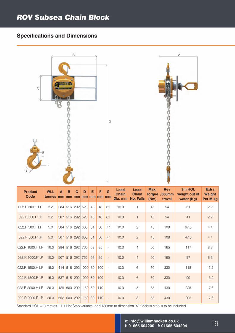
ProductCode
WLLtonnes
Amm
Bmm
Cmm
Dmm
Emm
Fmm
Gmm
Load Chain
Dia. mm
Load Chain
No, Falls
Max.Torque(Nm)
Rev/300mmtravel
3m HOLweight out of
water (Kg)
Extra Weight
Per M kg
022.R.300.H1.P 3.2 384 516 292 520 43 48 61 10.0 1 45 54 61 2.2
022.R.300.F1.P 3.2 507 516 292 520 43 48 61 10.0 1 45 54 41 2.2
022.R.500.H1.P 5.0 384 516 292 600 51 60 77 10.0 2 45 108 67.5 4.4
022.R.500.F1.P 5.0 507 516 292 600 51 60 77 10.0 2 45 108 47.5 4.4
022.R.1000.H1.P 10.0 384 516 292 760 53 85 - 10.0 4 50 165 117 8.8
022.R.1000.F1.P 10.0 507 516 292 760 53 85 - 10.0 4 50 165 97 8.8
022.R.1500.H1.P 15.0 414 516 292 1000 80 100 - 10.0 6 50 330 118 13.2
022.R.1500.F1.P 15.0 537 516 292 1000 80 100 - 10.0 6 50 330 99 13.2
022.R.2000.H1.P 20.0 429 600 292 1150 80 110 - 10.0 8 55 430 225 17.6
022.R.2000.F1.P 20.0 552 600 292 1150 80 110 - 10.0 8 55 430 205 17.6
Specifications and Dimensions
19e: [email protected]: 01665 604200 f: 01665 604204
Standard HOL = 3 metres. H1 Hot Stab variants: add 186mm to dimension ‘A’ if debris stab is to be included.
B A
C
D
E
G
F
ROV Subsea Chain Block
williamhackett.co.uk
Fleeting adviceSafe use of Manual Chain Hoists at angles away from the
vertical (0-45°).
The following guidance is for the safe use of manual chain
hoists when being used away from the vertical (0°) and when
lifting and moving a load in conjunction with additional manual
chain hoists (fleeting/cross hauling). These lifting operations
should be assessed by a competent person.
• Top Hook Suspension - the suspension point must be
the correct size to admit the top hook and allow it to rest
correctly in the bowl of the hook. It must have sufficient
clearance to allow the top hook to articulate within it.
• The suspension point must have a safe working load equal
to or greater than the load to be lifted.
• Bottom Hook Attachment - the attachment point onto the
load must be of the correct size to admit the bottom hook
and allow it to rest correctly in the bowl of the hook, and to
articulate within it.
• Make sure that the load chain is free from any twists or
knotting and in respect of multi-fall manual chain hoists
that the bottom hook has not been capsized.
• When using a manual hoist at any angle away from the
vertical in a lifting operation in conjunction with additional
manual chain hoists make sure that:
• Both top and bottom hooks are correctly loaded in the
saddle of the hook.
• Both the top and bottom hooks are free to rotate on
their attachment points and do not become trapped
or jammed causing stress points on the hook or hook
housing.
• Both the top and bottom attachment points are
designed to work at angles away from the vertical.
• Check the area around the load and assess if the load
will move between hoists during the lifting operation.
• Ensure that both the top hook, bottom hook, chain hoist
carcass and load chain are all in line.
• When using multiple manual chain hoists to lift and move
a single load, the load should not exceed the SWL of any
individual manual hoist being used for that lift.
Important: Make sure hoist has an adequate length of load
chain to raise or lower the load in a safe manner. Do not attempt
to lower hoist beyond its limit.
Selection for specific underwater lifting applicationThe harsh conditions experienced at subsea worksites
undoubtedly have an adverse effect on any chain hoist used in
that environment. The salt water conditions accelerate corrosion
within the unit, the immersion in water may wash grease from
internal parts and particles suspended in the water can affect
the ability of the brake to hold the load. The Hackett ROV SS-C4
chain hoist is manufactured with specifically designed features
to cope with these extreme operating conditions.
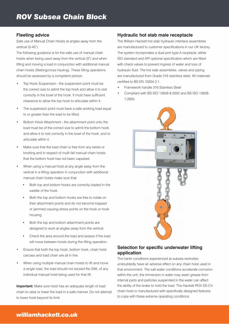
Hydraulic hot stab male receptacleThe William Hackett hot stab hydraulic interface assemblies
are manufactured to customer specifications in our UK factory.
The system incorporates a dual port type A recptacle, either
ISO standard and API optional specification which are fitted
with check valves to prevent ingress of water and loss of
hydraulic fluid. The hot stab assemblies, valves and piping
are manufactured from Grade 316 stainless steel. All materials
certified to BS EN 10204 3.1.
• Framework handle 316 Stainless Steel
• Compliant with BS ISO 13626-8:2002 and BS ISO 13628-
1:2005.
Subsea William Hackett SS-L5 Lever Hoist
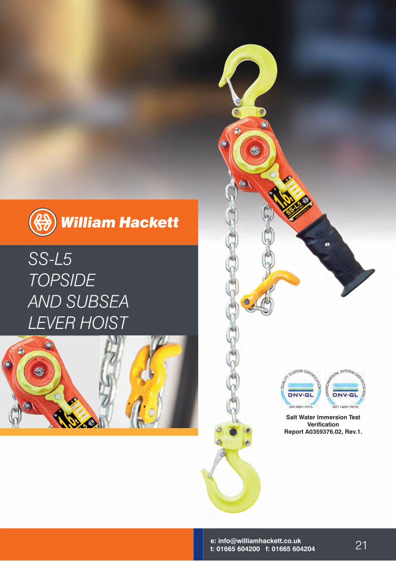
SS-L5TOPSIDEAND SUBSEALEVER HOIST
21e: [email protected]: 01665 604200 f: 01665 604204
Salt Water Immersion Test Verification
Report A0359376.02, Rev.1.

williamhackett.co.uk
Hackett SS-L5 Topside and Subsea Lever Hoist
23e: [email protected]: 01665 604200 f: 01665 604204
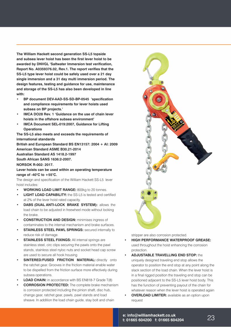
stripper are also corrosion protected.• HIGH PERFORMANCE WATERPROOF GREASE:
used throughout the hoist enhancing the corrosion protection.
• ADJUSTABLE TRAVELLING END STOP: the uniquely designed traveling end stop allows the operator to position the end stop at any point along the slack section of the load chain. When the lever hoist is in a final rigged position the traveling end stop can be positioned adjacent to the SS-L5 lever hoist body. This has the function of preventing payout of the chain for whatever reason when the lever hoist is operated again
• OVERLOAD LIMITER: available as an option upon request
The William Hackett second generation SS-L5 topside and subsea lever hoist has been the first lever hoist to be awarded by DNVGL ‘Saltwater Immersion test verification, Report No. A0359376.02, Rev.1. The report verifies that the SS-L5 type lever hoist could be safely used over a 21 day single immersion and a 31 day multi immersion period. The design features, testing and guidance for use, maintenance and storage of the SS-L5 has also been developed in line with:• BP document DEV-AAD-SS-SD-BP-0545 ‘specification
and compliance requirements for lever hoists used subsea on BP projects.’
• IMCA DO28 Rev. 1 ‘Guidance on the use of chain lever hoists in the offshore subsea environment’
• IMCA Document SEL-019:2007, Guidance for Lifting Operations
The SS-L5 also meets and exceeds the requirements of international standardsBritish and European Standard BS EN13157: 2004 + AI: 2009American Standard ASME B30.21-2014Australian Standard AS 1418.2-1997South African SANS 1636:2-2007.
NORSOK R-002: 2017.Lever hoists can be used within an operating temperature range of -40°C to +55°C.The design and specification of the William Hackett SS-L5 lever hoist includes:• WORKING LOAD LIMIT RANGE: 800kg to 20 tonnes.• LIGHT LOAD CAPABILITY: the SS-L5 is tested and certified
at 2% of the lever hoist rated capacity.• DABS (DUAL ANTI-LOCK BRAKE SYSTEM): allows the
load chain to be adjusted in freewheel mode without locking the brake.
• CONSTRUCTION AND DESIGN: minimises ingress of contaminates to the internal mechanism and brake surfaces.
• STAINLESS STEEL PAWL SPRINGS: secured internally to reduce risk of damage.
• STAINLESS STEEL FIXINGS: All internal springs are stainless steel, circ clips securing the pawls onto the pawl stands, stainless steel nyloc nuts and socket head cap screw are used to secure all hook housing
• SINTERED/FUSED FRICTION MATERIAL: directly onto the ratchet gear. Grooves in the friction material enable water to be dispelled from the friction surface more effectively during subsea operations.
• LOAD CHAIN: in accordance with BS EN818-7 Grade T(8) • CORROSION PROTECTED: The complete brake mechanism
is corrosion protected including the pinion shaft, disc hub, change gear, ratchet gear, pawls, pawl stands and load sheave. In addition the load chain guide, stay bolt and chain
williamhackett.co.uk
Hackett SS-L5 Topside and Subsea Lever Hoist
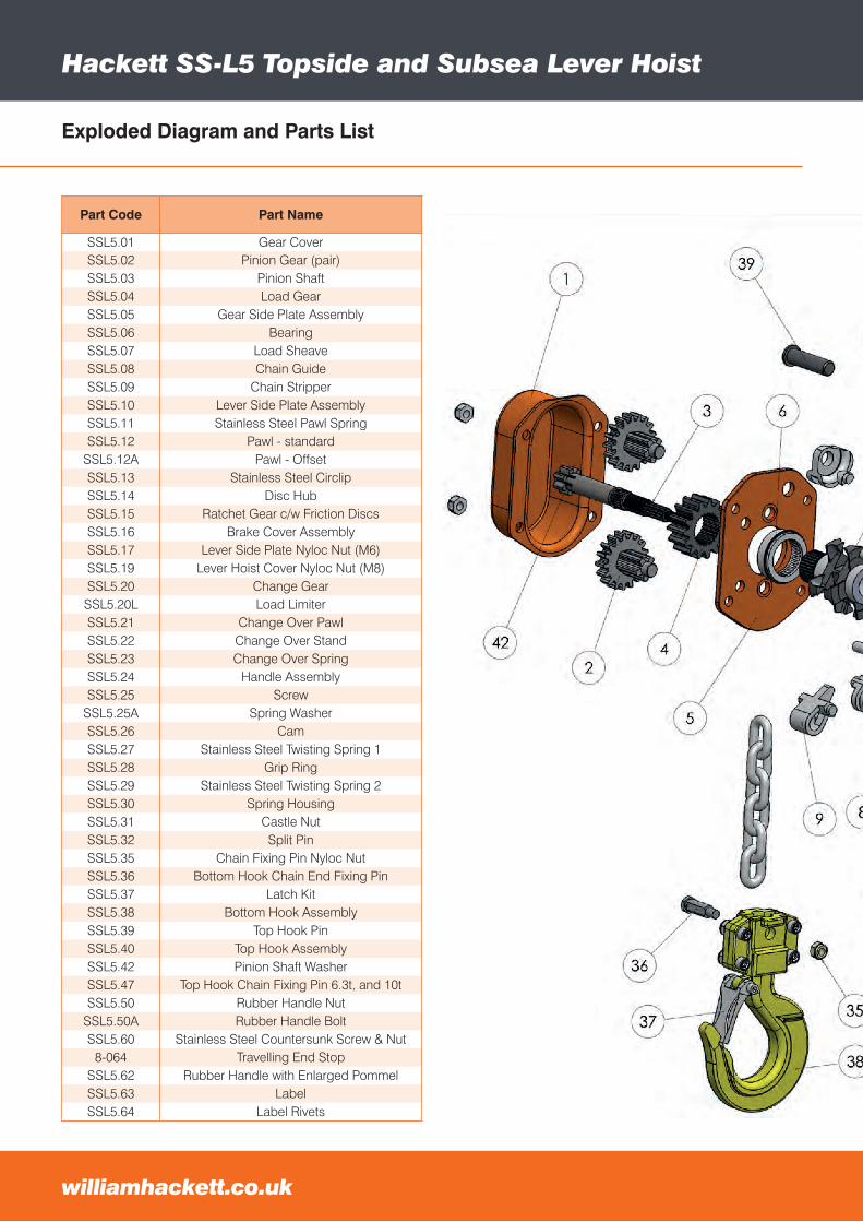
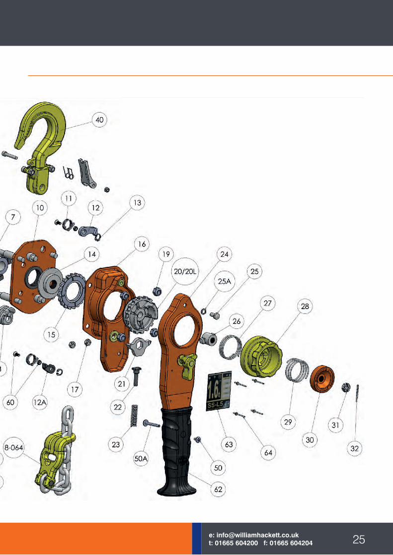
Exploded Diagram and Parts List
Part Code Part Name
SSL5.01 Gear CoverSSL5.02 Pinion Gear (pair)SSL5.03 Pinion ShaftSSL5.04 Load GearSSL5.05 Gear Side Plate AssemblySSL5.06 BearingSSL5.07 Load SheaveSSL5.08 Chain GuideSSL5.09 Chain StripperSSL5.10 Lever Side Plate AssemblySSL5.11 Stainless Steel Pawl SpringSSL5.12 Pawl - standard
SSL5.12A Pawl - OffsetSSL5.13 Stainless Steel CirclipSSL5.14 Disc HubSSL5.15 Ratchet Gear c/w Friction DiscsSSL5.16 Brake Cover AssemblySSL5.17 Lever Side Plate Nyloc Nut (M6)SSL5.19 Lever Hoist Cover Nyloc Nut (M8)SSL5.20 Change GearSSL5.20L Load LimiterSSL5.21 Change Over PawlSSL5.22 Change Over StandSSL5.23 Change Over SpringSSL5.24 Handle AssemblySSL5.25 Screw
SSL5.25A Spring WasherSSL5.26 CamSSL5.27 Stainless Steel Twisting Spring 1SSL5.28 Grip RingSSL5.29 Stainless Steel Twisting Spring 2SSL5.30 Spring HousingSSL5.31 Castle NutSSL5.32 Split PinSSL5.35 Chain Fixing Pin Nyloc NutSSL5.36 Bottom Hook Chain End Fixing PinSSL5.37 Latch KitSSL5.38 Bottom Hook AssemblySSL5.39 Top Hook PinSSL5.40 Top Hook AssemblySSL5.42 Pinion Shaft WasherSSL5.47 Top Hook Chain Fixing Pin 6.3t, and 10tSSL5.50 Rubber Handle Nut
SSL5.50A Rubber Handle BoltSSL5.60 Stainless Steel Countersunk Screw & Nut
8-064 Travelling End StopSSL5.62 Rubber Handle with Enlarged PommelSSL5.63 LabelSSL5.64 Label Rivets
25e: [email protected]: 01665 604200 f: 01665 604204
williamhackett.co.uk
Hackett SS-L5 Topside and Subsea Lever Hoist
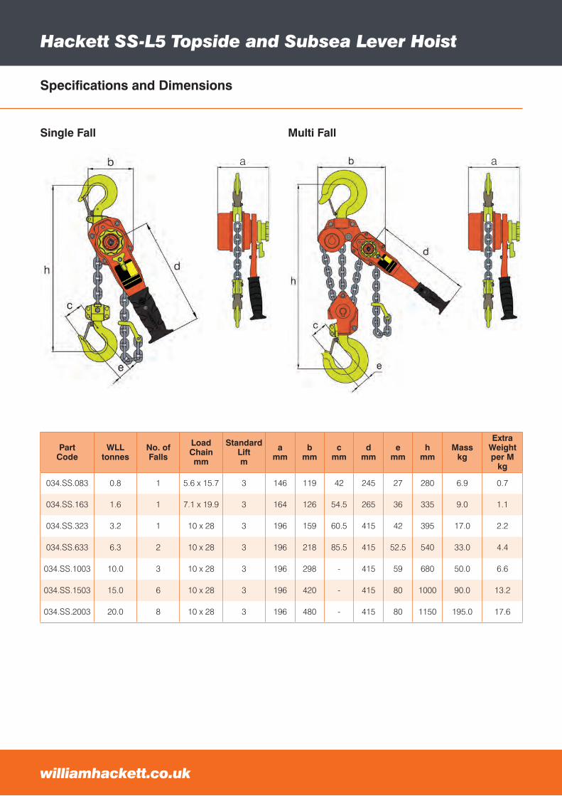
Specifications and Dimensions
Part Code
WLLtonnes
No. of Falls
Load Chainmm
Standard Liftm
amm
bmm
cmm
dmm
emm
hmm
Masskg
Extra Weightper M
kg
034.SS.083 0.8 1 5.6 x 15.7 3 146 119 42 245 27 280 6.9 0.7
034.SS.163 1.6 1 7.1 x 19.9 3 164 126 54.5 265 36 335 9.0 1.1
034.SS.323 3.2 1 10 x 28 3 196 159 60.5 415 42 395 17.0 2.2
034.SS.633 6.3 2 10 x 28 3 196 218 85.5 415 52.5 540 33.0 4.4
034.SS.1003 10.0 3 10 x 28 3 196 298 - 415 59 680 50.0 6.6
034.SS.1503 15.0 6 10 x 28 3 196 420 - 415 80 1000 90.0 13.2
034.SS.2003 20.0 8 10 x 28 3 196 480 - 415 80 1150 195.0 17.6
Single Fall
a
Multi Fall
a
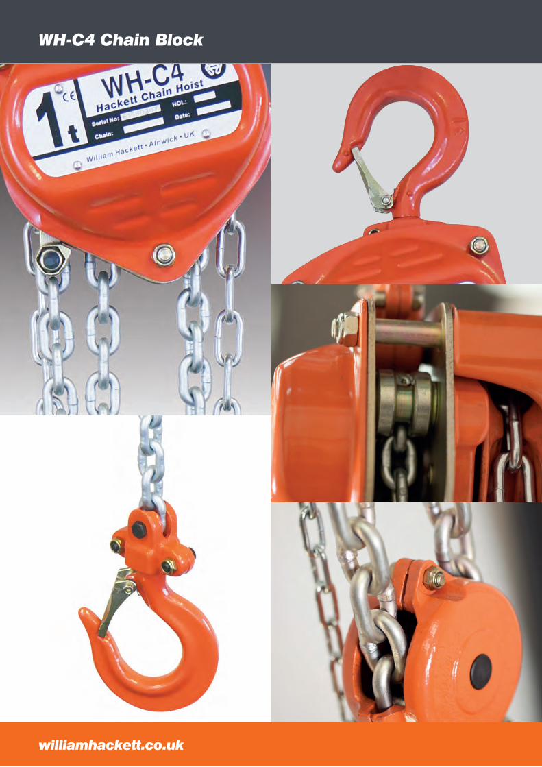
WH-C4 Chain Block
williamhackett.co.uk
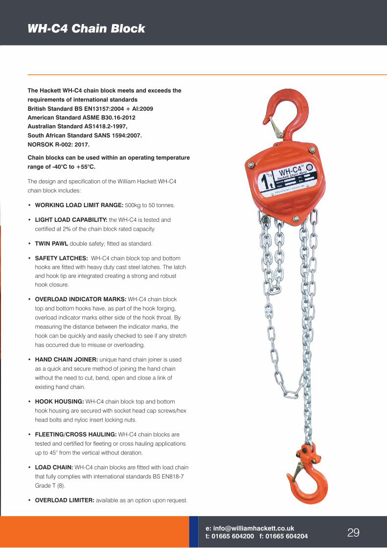
The Hackett WH-C4 chain block meets and exceeds the
requirements of international standards
British Standard BS EN13157:2004 + AI:2009American Standard ASME B30.16-2012 Australian Standard AS1418.2-1997,
South African Standard SANS 1594:2007.
NORSOK R-002: 2017.
Chain blocks can be used within an operating temperature
range of -40°C to +55°C.
The design and specification of the William Hackett WH-C4
chain block includes:
• WORKING LOAD LIMIT RANGE: 500kg to 50 tonnes.
• LIGHT LOAD CAPABILITY: the WH-C4 is tested and
certified at 2% of the chain block rated capacity.
• TWIN PAWL double safety; fitted as standard.
• SAFETY LATCHES: WH-C4 chain block top and bottom hooks are fitted with heavy duty cast steel latches. The latch and hook tip are integrated creating a strong and robust hook closure.
• OVERLOAD INDICATOR MARKS: WH-C4 chain block
top and bottom hooks have, as part of the hook forging,
overload indicator marks either side of the hook throat. By
measuring the distance between the indicator marks, the
hook can be quickly and easily checked to see if any stretch
has occurred due to misuse or overloading.
• HAND CHAIN JOINER: unique hand chain joiner is used
as a quick and secure method of joining the hand chain
without the need to cut, bend, open and close a link of
existing hand chain.
• HOOK HOUSING: WH-C4 chain block top and bottom
hook housing are secured with socket head cap screws/hex
head bolts and nyloc insert locking nuts.
• FLEETING/CROSS HAULING: WH-C4 chain blocks are
tested and certified for fleeting or cross hauling applications
up to 45° from the vertical without deration.
• LOAD CHAIN: WH-C4 chain blocks are fitted with load chain
that fully complies with international standards BS EN818-7
Grade T (8).
• OVERLOAD LIMITER: available as an option upon request.
WH-C4 Chain Block
29e: [email protected]: 01665 604200 f: 01665 604204
1
2
3
4
5
7
89
10
11
12
13
14
15
16
17
18
1920
21
2223
2425
26
27
28
29
3031
32
33
34
35
29L29L29L
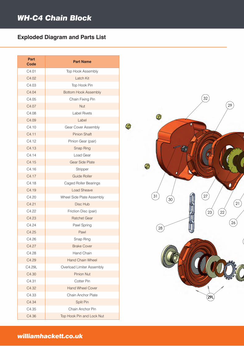
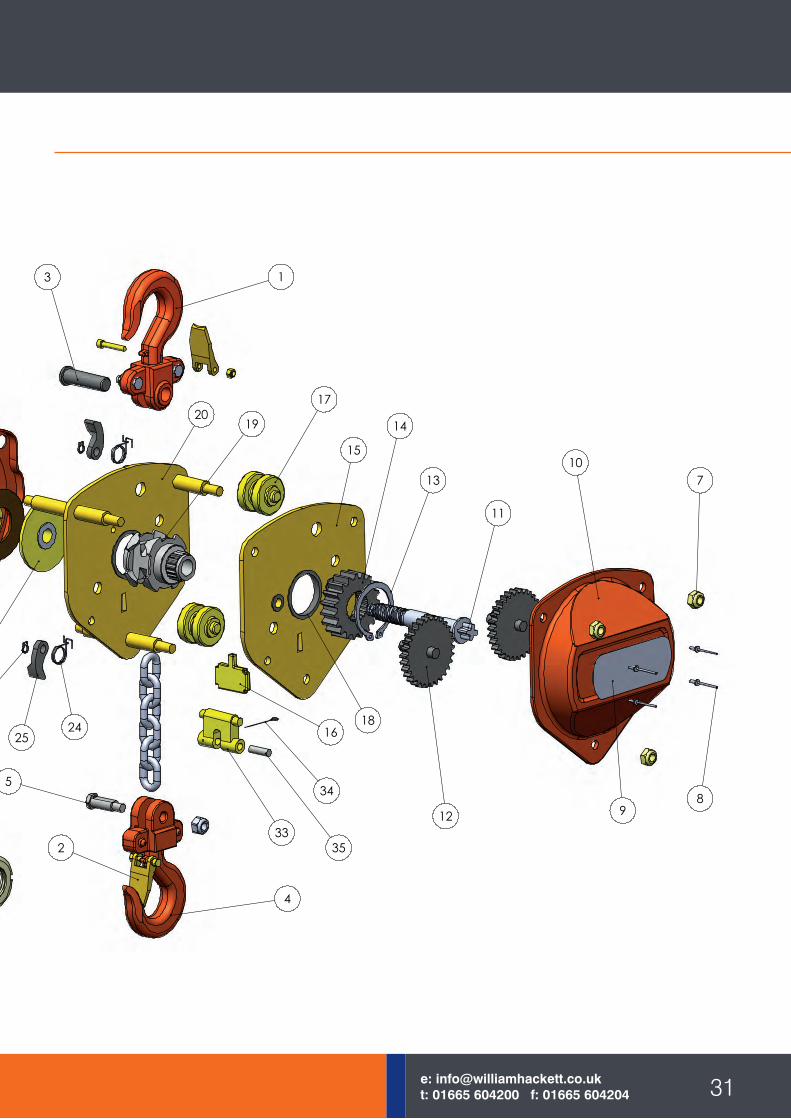
Exploded Diagram and Parts List
WH-C4 Chain Block
williamhackett.co.uk
Part Code
Part Name
C4.01 Top Hook Assembly
C4.02 Latch Kit
C4.03 Top Hook Pin
C4.04 Bottom Hook Assembly
C4.05 Chain Fixing Pin
C4.07 Nut
C4.08 Label Rivets
C4.09 Label
C4.10 Gear Cover Assembly
C4.11 Pinion Shaft
C4.12 Pinion Gear (pair)
C4.13 Snap Ring
C4.14 Load Gear
C4.15 Gear Side Plate
C4.16 Stripper
C4.17 Guide Roller
C4.18 Caged Roller Bearings
C4.19 Load Sheave
C4.20 Wheel Side Plate Assembly
C4.21 Disc Hub
C4.22 Friction Disc (pair)
C4.23 Ratchet Gear
C4.24 Pawl Spring
C4.25 Pawl
C4.26 Snap Ring
C4.27 Brake Cover
C4.28 Hand Chain
C4.29 Hand Chain Wheel
C4.29L Overload Limiter Assembly
C4.30 Pinion Nut
C4.31 Cotter Pin
C4.32 Hand Wheel Cover
C4.33 Chain Anchor Plate
C4.34 Split Pin
C4.35 Chain Anchor Pin
C4.36 Top Hook Pin and Lock Nut
31e: [email protected]: 01665 604200 f: 01665 604204
1
2
3
4
5
7
89
10
11
12
13
14
15
16
17
18
1920
21
2223
2425
26
27
28
29
3031
32
33
34
35
29L29L29L
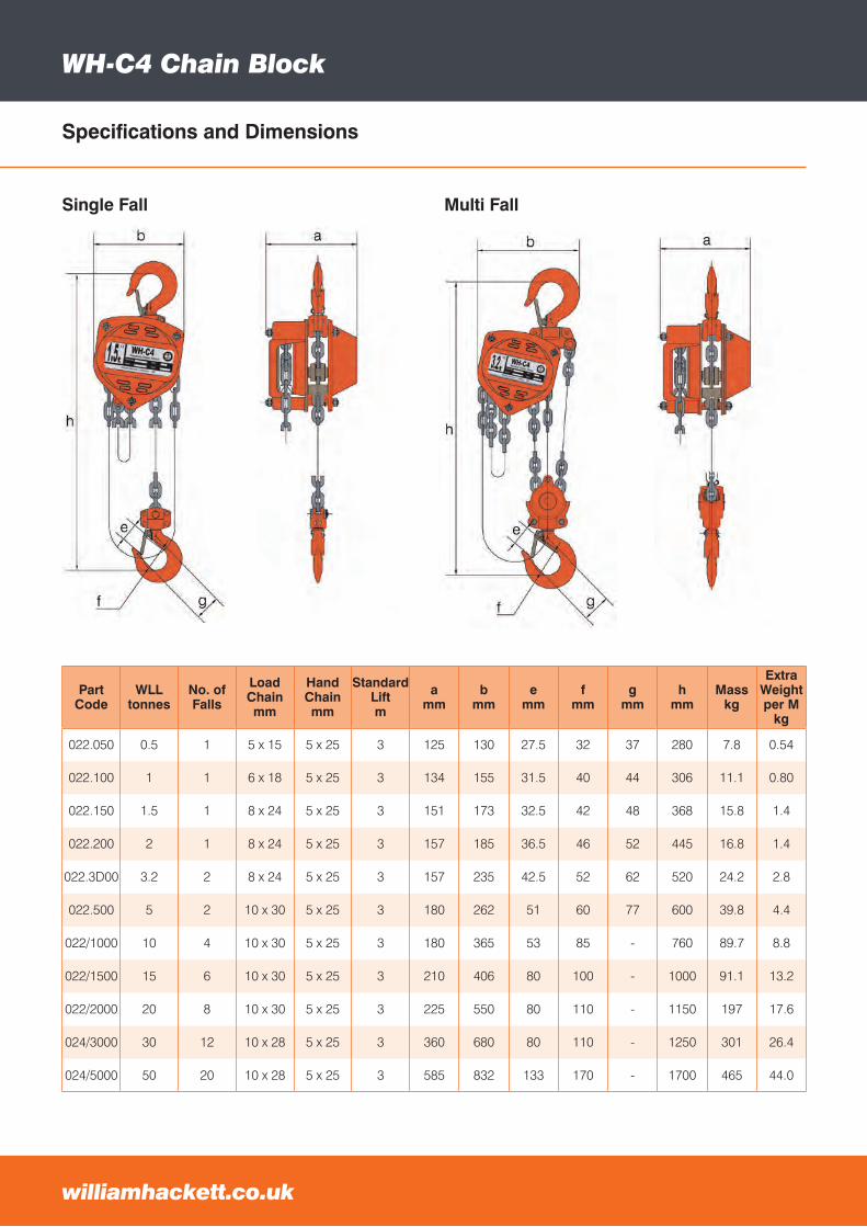
Specifications and Dimensions
WH-C4 Chain Block
Part Code
WLLtonnes
No. of Falls
Load Chainmm
HandChainmm
Standard Liftm
amm
bmm
emm
fmm
gmm
hmm
Masskg
Extra Weightper M
kg
022.050 0.5 1 5 x 15 5 x 25 3 125 130 27.5 32 37 280 7.8 0.54
022.100 1 1 6 x 18 5 x 25 3 134 155 31.5 40 44 306 11.1 0.80
022.150 1.5 1 8 x 24 5 x 25 3 151 173 32.5 42 48 368 15.8 1.4
022.200 2 1 8 x 24 5 x 25 3 157 185 36.5 46 52 445 16.8 1.4
022.3D00 3.2 2 8 x 24 5 x 25 3 157 235 42.5 52 62 520 24.2 2.8
022.500 5 2 10 x 30 5 x 25 3 180 262 51 60 77 600 39.8 4.4
022/1000 10 4 10 x 30 5 x 25 3 180 365 53 85 - 760 89.7 8.8
022/1500 15 6 10 x 30 5 x 25 3 210 406 80 100 - 1000 91.1 13.2
022/2000 20 8 10 x 30 5 x 25 3 225 550 80 110 - 1150 197 17.6
024/3000 30 12 10 x 28 5 x 25 3 360 680 80 110 - 1250 301 26.4
024/5000 50 20 10 x 28 5 x 25 3 585 832 133 170 - 1700 465 44.0
Single Fall
williamhackett.co.uk
Multi Fall
33e: [email protected]: 01665 604200 f: 01665 604204
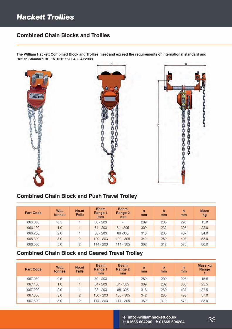
Hackett Trollies
Combined Chain Blocks and Trollies
Combined Chain Block and Geared Travel Trolley
Part Code WLLtonnes
No.ofFalls
BeamRange 1
mm
BeamRange 2
mm
amm
bmm
hmm
Masskg
066.050 0.5 1 50 - 203 - 289 200 295 15.0
066.100 1.0 1 64 - 203 64 - 305 309 232 305 22.0
066.200 2.0 1 88 - 203 88 -305 318 260 437 34.0
066.300 3.0 2 100 - 203 100 - 305 342 280 493 53.0
066.500 5.0 2 114 - 203 114 - 305 362 312 573 80.0
Part Code WLLtonnes
No.ofFalls
BeamRange 1
mm
BeamRange 2
mm
amm
bmm
hmm
Mass kgRange
1
067.050 0.5 1 50 - 203 - 289 200 295 15.6
067.100 1.0 1 64 - 203 64 - 305 309 232 305 25.5
067.200 2.0 1 88 - 203 88 -305 318 260 437 37.5
067.300 3.0 2 100 - 203 100 - 305 342 280 493 57.0
067.500 5.0 2 114 - 203 114 - 305 362 312 573 83.0
Combined Chain Block and Push Travel Trolley
The William Hackett Combined Block and Trollies meet and exceed the requirements of international standard and British Standard BS EN 13157:2004 + AI:2009.
Hackett Trollies
williamhackett.co.uk
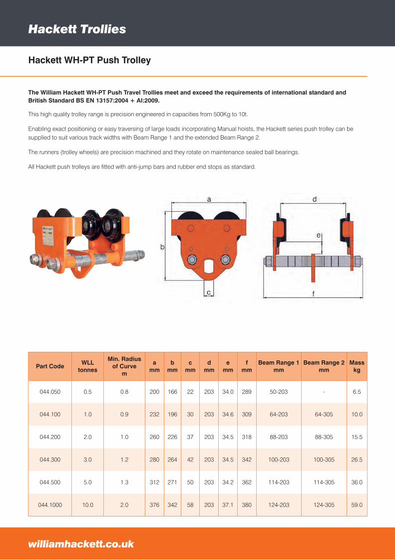
Hackett WH-PT Push Trolley
This high quality trolley range is precision engineered in capacities from 500Kg to 10t.
Enabling exact positioning or easy traversing of large loads incorporating Manual hoists, the Hackett series push trolley can be supplied to suit various track widths with Beam Range 1 and the extended Beam Range 2.
The runners (trolley wheels) are precision machined and they rotate on maintenance sealed ball bearings.
All Hackett push trolleys are fitted with anti-jump bars and rubber end stops as standard.
Part CodeWLL
tonnes
Min. Radiusof Curve
m
amm
bmm
cmm
dmm
emm
fmm
Beam Range 1 mm
Beam Range 2 mm
Mass kg
044.050 0.5 0.8 200 166 22 203 34.0 289 50-203 - 6.5
044.100 1.0 0.9 232 196 30 203 34.6 309 64-203 64-305 10.0
044.200 2.0 1.0 260 226 37 203 34.5 318 88-203 88-305 15.5
044.300 3.0 1.2 280 264 42 203 34.5 342 100-203 100-305 26.5
044.500 5.0 1.3 312 271 50 203 34.2 362 114-203 114-305 36.0
044.1000 10.0 2.0 376 342 58 203 37.1 380 124-203 124-305 59.0
The William Hackett WH-PT Push Travel Trollies meet and exceed the requirements of international standard and British Standard BS EN 13157:2004 + AI:2009.
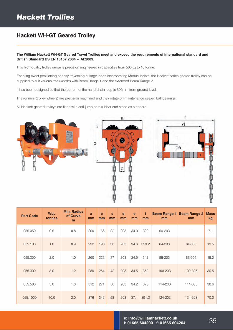
Hackett WH-GT Geared Trolley
This high quality trolley range is precision engineered in capacities from 500Kg to 10 tonne.
Enabling exact positioning or easy traversing of large loads incorporating Manual hoists, the Hackett series geared trolley can be supplied to suit various track widths with Beam Range 1 and the extended Beam Range 2.
It has been designed so that the bottom of the hand chain loop is 500mm from ground level.
The runners (trolley wheels) are precision machined and they rotate on maintenance sealed ball bearings.
All Hackett geared trolleys are fitted with anti-jump bars rubber end stops as standard.
Part CodeWLL
tonnes
Min. Radiusof Curve
m
amm
bmm
cmm
dmm
emm
fmm
Beam Range 1 mm
Beam Range 2 mm
Mass kg
055.050 0.5 0.8 200 166 22 203 34.0 320 50-203 - 7.1
055.100 1.0 0.9 232 196 30 203 34.6 333.2 64-203 64-305 13.5
055.200 2.0 1.0 260 226 37 203 34.5 342 88-203 88-305 19.0
055.300 3.0 1.2 280 264 42 203 34.5 352 100-203 100-305 30.5
055.500 5.0 1.3 312 271 50 203 34.2 370 114-203 114-305 38.6
055.1000 10.0 2.0 376 342 58 203 37.1 391.2 124-203 124-203 70.0
Hackett Trollies
35e: [email protected]: 01665 604200 f: 01665 604204
The William Hackett WH-GT Geared Travel Trollies meet and exceed the requirements of international standard and British Standard BS EN 13157:2004 + AI:2009.
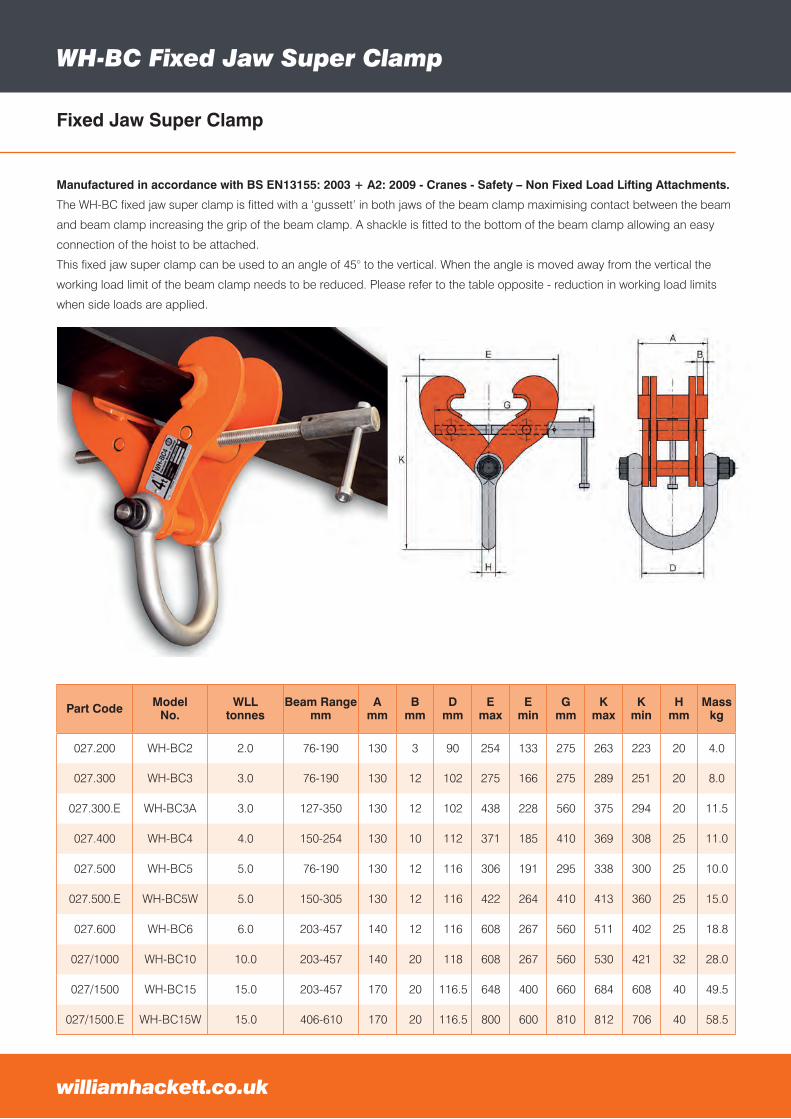
WH-BC Fixed Jaw Super Clamp
Part Code ModelNo.
WLLtonnes
Beam Rangemm
Amm
Bmm
Dmm
Emax
Emin
Gmm
Kmax
Kmin
Hmm
Masskg
027.200 WH-BC2 2.0 76-190 130 3 90 254 133 275 263 223 20 4.0
027.300 WH-BC3 3.0 76-190 130 12 102 275 166 275 289 251 20 8.0
027.300.E WH-BC3A 3.0 127-350 130 12 102 438 228 560 375 294 20 11.5
027.400 WH-BC4 4.0 150-254 130 10 112 371 185 410 369 308 25 11.0
027.500 WH-BC5 5.0 76-190 130 12 116 306 191 295 338 300 25 10.0
027.500.E WH-BC5W 5.0 150-305 130 12 116 422 264 410 413 360 25 15.0
027.600 WH-BC6 6.0 203-457 140 12 116 608 267 560 511 402 25 18.8
027/1000 WH-BC10 10.0 203-457 140 20 118 608 267 560 530 421 32 28.0
027/1500 WH-BC15 15.0 203-457 170 20 116.5 648 400 660 684 608 40 49.5
027/1500.E WH-BC15W 15.0 406-610 170 20 116.5 800 600 810 812 706 40 58.5
Manufactured in accordance with BS EN13155: 2003 + A2: 2009 - Cranes - Safety – Non Fixed Load Lifting Attachments.
The WH-BC fixed jaw super clamp is fitted with a ‘gussett’ in both jaws of the beam clamp maximising contact between the beam
and beam clamp increasing the grip of the beam clamp. A shackle is fitted to the bottom of the beam clamp allowing an easy
connection of the hoist to be attached.
This fixed jaw super clamp can be used to an angle of 45° to the vertical. When the angle is moved away from the vertical the
working load limit of the beam clamp needs to be reduced. Please refer to the table opposite - reduction in working load limits
when side loads are applied.
williamhackett.co.uk
Fixed Jaw Super Clamp
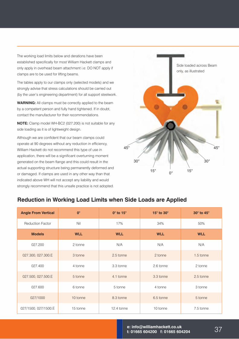
Reduction in Working Load Limits when Side Loads are Applied
Angle From Vertical 0° 0° to 15° 15° to 30° 30° to 45°
Reduction Factor Nil 17% 34% 50%
Models WLL WLL WLL WLL
027.200 2 tonne N/A N/A N/A
027.300, 027.300.E 3 tonne 2.5 tonne 2 tonne 1.5 tonne
027.400 4 tonne 3.3 tonne 2.6 tonne 2 tonne
027.500, 027.500.E 5 tonne 4.1 tonne 3.3 tonne 2.5 tonne
027.600 6 tonne 5 tonne 4 tonne 3 tonne
027/1000 10 tonne 8.3 tonne 6.5 tonne 5 tonne
027/1500, 027/1500.E 15 tonne 12.4 tonne 10 tonne 7.5 tonne
The working load limits below and derations have been
established specifically for most William Hackett clamps and
only apply in overhead beam attachment i.e: DO NOT apply if
clamps are to be used for lifting beams.
The tables apply to our clamps only (selected models) and we
strongly advise that stress calculations should be carried out
(by the user’s engineering department) for all support steelwork.
WARNING: All clamps must be correctly applied to the beam
by a competent person and fully hand tightened. If in doubt,
contact the manufacturer for their recommendations.
NOTE: Clamp model WH-BC2 (027.200) is not suitable for any
side loading as it is of lightweight design.
Although we are confident that our beam clamps could
operate at 90 degrees without any reduction in efficiency,
William Hackett do not recommend this type of use in
application, there will be a significant overturning moment
generated on the beam flange and this could result in the
actual supporting structure being permanently deformed and
or damaged. If clamps are used in any other way than that
indicated above WH will not accept any liability and would
strongly recommend that this unsafe practice is not adopted.
0°15° 15°
30° 30°
45° 45°
Side loaded across Beam
only, as illustrated
37e: [email protected]: 01665 604200 f: 01665 604204
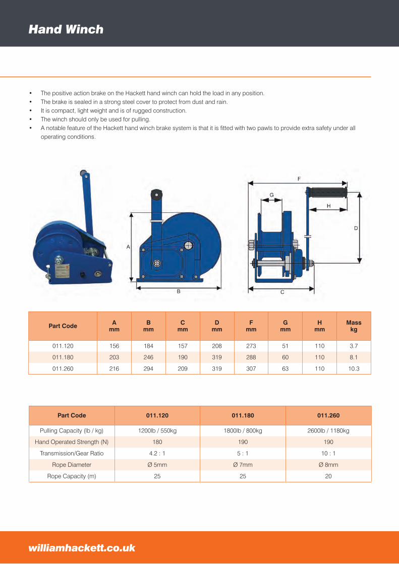
Hand Winch
williamhackett.co.uk
Part Code Amm
Bmm
Cmm
Dmm
Fmm
Gmm
Hmm
Masskg
011.120 156 184 157 208 273 51 110 3.7
011.180 203 246 190 319 288 60 110 8.1
011.260 216 294 209 319 307 63 110 10.3
• The positive action brake on the Hackett hand winch can hold the load in any position.• The brake is sealed in a strong steel cover to protect from dust and rain.• It is compact, light weight and is of rugged construction.• The winch should only be used for pulling.• A notable feature of the Hackett hand winch brake system is that it is fitted with two pawls to provide extra safety under all
operating conditions.
Part Code 011.120 011.180 011.260
Pulling Capacity (lb / kg) 1200lb / 550kg 1800lb / 800kg 2600lb / 1180kg
Hand Operated Strength (N) 180 190 190
Transmission/Gear Ratio 4.2 : 1 5 : 1 10 : 1
Rope Diameter Ø 5mm Ø 7mm Ø 8mm
Rope Capacity (m) 25 25 20
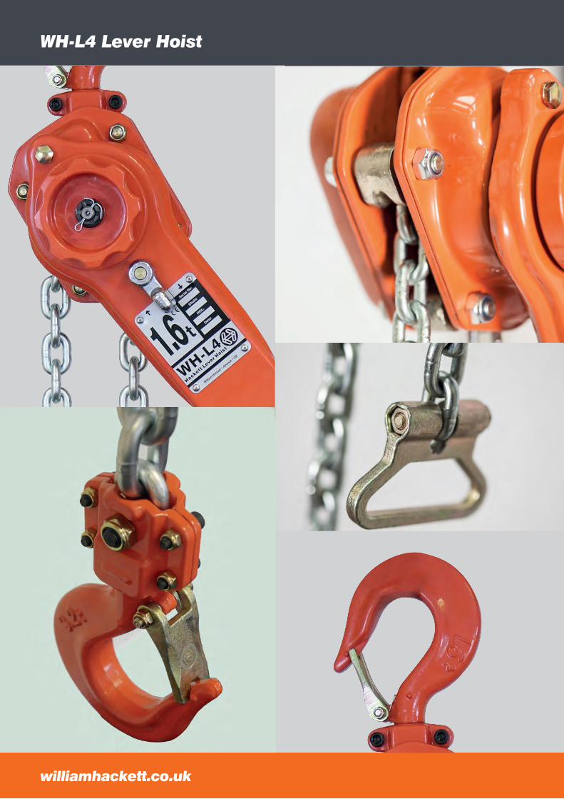
WH-L4 Lever Hoist
williamhackett.co.uk
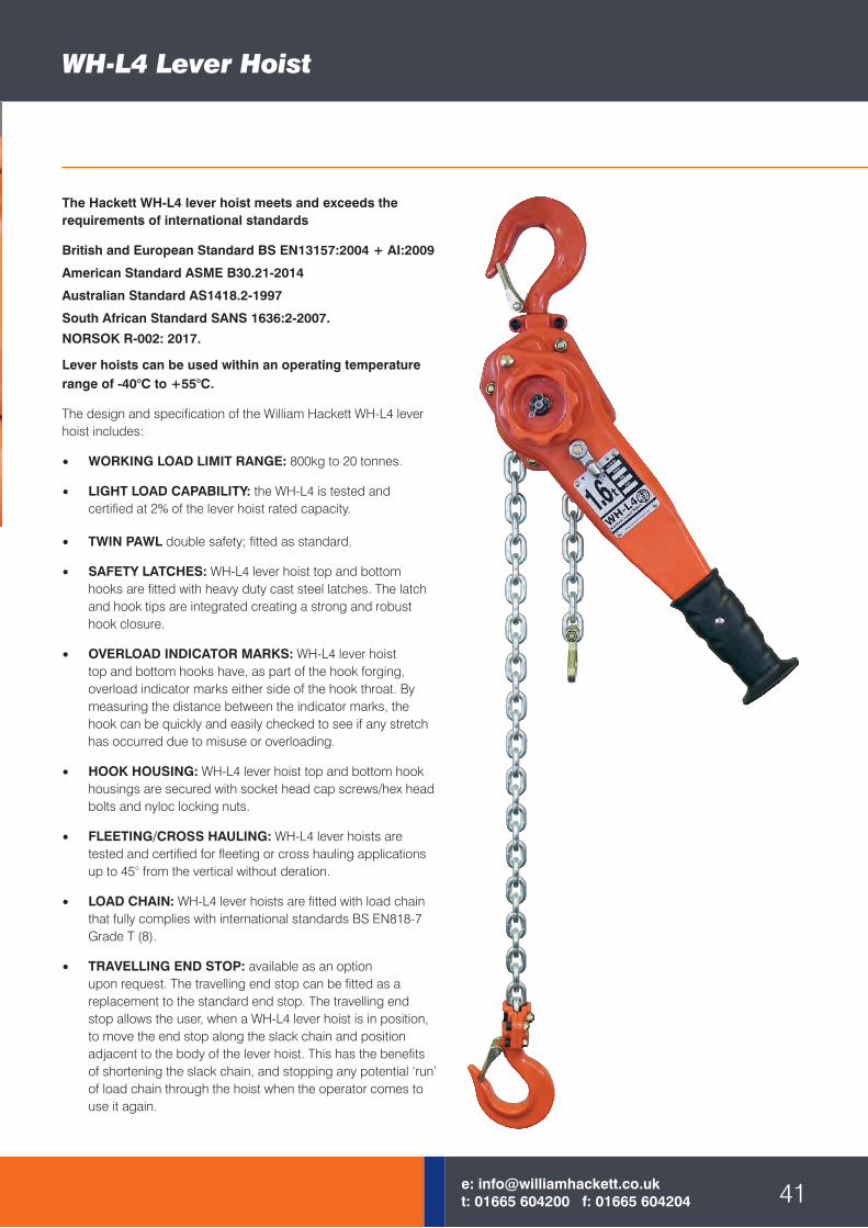
The Hackett WH-L4 lever hoist meets and exceeds the requirements of international standards
British and European Standard BS EN13157:2004 + AI:2009
American Standard ASME B30.21-2014
Australian Standard AS1418.2-1997
South African Standard SANS 1636:2-2007.
NORSOK R-002: 2017.
Lever hoists can be used within an operating temperature range of -40°C to +55°C.
The design and specification of the William Hackett WH-L4 lever hoist includes:
• WORKING LOAD LIMIT RANGE: 800kg to 20 tonnes.
• LIGHT LOAD CAPABILITY: the WH-L4 is tested and certified at 2% of the lever hoist rated capacity.
• TWIN PAWL double safety; fitted as standard.
• SAFETY LATCHES: WH-L4 lever hoist top and bottom hooks are fitted with heavy duty cast steel latches. The latch and hook tips are integrated creating a strong and robust hook closure.
• OVERLOAD INDICATOR MARKS: WH-L4 lever hoist top and bottom hooks have, as part of the hook forging, overload indicator marks either side of the hook throat. By measuring the distance between the indicator marks, the hook can be quickly and easily checked to see if any stretch has occurred due to misuse or overloading.
• HOOK HOUSING: WH-L4 lever hoist top and bottom hook housings are secured with socket head cap screws/hex head bolts and nyloc locking nuts.
• FLEETING/CROSS HAULING: WH-L4 lever hoists are tested and certified for fleeting or cross hauling applications up to 45° from the vertical without deration.
• LOAD CHAIN: WH-L4 lever hoists are fitted with load chain that fully complies with international standards BS EN818-7 Grade T (8).
• TRAVELLING END STOP: available as an option upon request. The travelling end stop can be fitted as a replacement to the standard end stop. The travelling end stop allows the user, when a WH-L4 lever hoist is in position, to move the end stop along the slack chain and position adjacent to the body of the lever hoist. This has the benefits of shortening the slack chain, and stopping any potential ‘run’ of load chain through the hoist when the operator comes to use it again.
WH-L4 Lever Hoist
41e: [email protected]: 01665 604200 f: 01665 604204
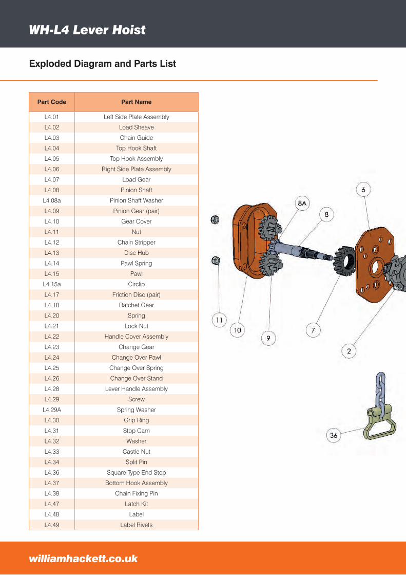
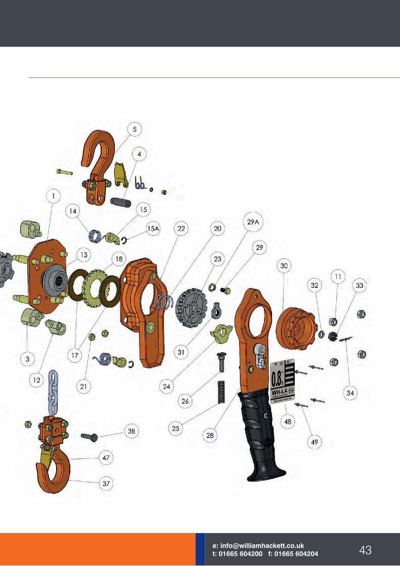
Exploded Diagram and Parts List
WH-L4 Lever Hoist
Part Code Part Name
L4.01 Left Side Plate Assembly
L4.02 Load Sheave
L4.03 Chain Guide
L4.04 Top Hook Shaft
L4.05 Top Hook Assembly
L4.06 Right Side Plate Assembly
L4.07 Load Gear
L4.08 Pinion Shaft
L4.08a Pinion Shaft Washer
L4.09 Pinion Gear (pair)
L4.10 Gear Cover
L4.11 Nut
L4.12 Chain Stripper
L4.13 Disc Hub
L4.14 Pawl Spring
L4.15 Pawl
L4.15a Circlip
L4.17 Friction Disc (pair)
L4.18 Ratchet Gear
L4.20 Spring
L4.21 Lock Nut
L4.22 Handle Cover Assembly
L4.23 Change Gear
L4.24 Change Over Pawl
L4.25 Change Over Spring
L4.26 Change Over Stand
L4.28 Lever Handle Assembly
L4.29 Screw
L4.29A Spring Washer
L4.30 Grip Ring
L4.31 Stop Cam
L4.32 Washer
L4.33 Castle Nut
L4.34 Split Pin
L4.36 Square Type End Stop
L4.37 Bottom Hook Assembly
L4.38 Chain Fixing Pin
L4.47 Latch Kit
L4.48 Label
L4.49 Label Rivets
williamhackett.co.uk
43e: [email protected]: 01665 604200 f: 01665 604204
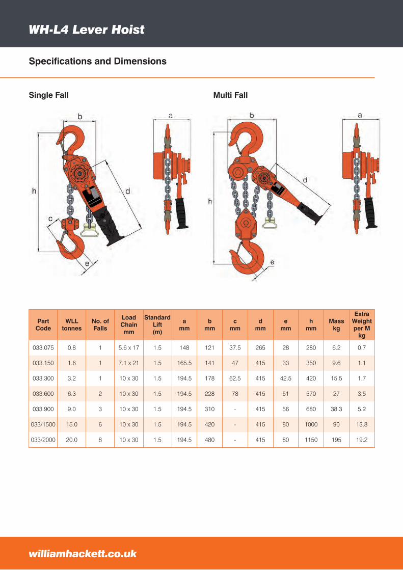
Specifications and Dimensions
WH-L4 Lever Hoist
Single Fall
Part Code
WLLtonnes
No. of Falls
Load Chainmm
Standard Lift(m)
amm
bmm
cmm
dmm
emm
hmm
Masskg
Extra Weightper M
kg
033.075 0.8 1 5.6 x 17 1.5 148 121 37.5 265 28 280 6.2 0.7
033.150 1.6 1 7.1 x 21 1.5 165.5 141 47 415 33 350 9.6 1.1
033.300 3.2 1 10 x 30 1.5 194.5 178 62.5 415 42.5 420 15.5 1.7
033.600 6.3 2 10 x 30 1.5 194.5 228 78 415 51 570 27 3.5
033.900 9.0 3 10 x 30 1.5 194.5 310 - 415 56 680 38.3 5.2
033/1500 15.0 6 10 x 30 1.5 194.5 420 - 415 80 1000 90 13.8
033/2000 20.0 8 10 x 30 1.5 194.5 480 - 415 80 1150 195 19.2
williamhackett.co.uk
a a
Multi Fall
a
45e: [email protected]: 01665 604200 f: 01665 604204
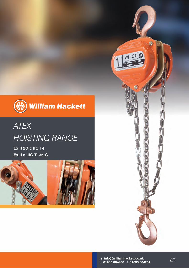
ATEXHOISTING RANGEEx II 2G c IIC T4
Ex II c IIIC T135°C
ATEX Hoisting Range
williamhackett.co.uk
Part Code
WLLtonnes
No.of
Falls
Load Chainmm
HandChainmm
Stand.Liftm
amm
bmm
emm
fmm
gmm
hmm
Masskg
Extra Weightper m
kg
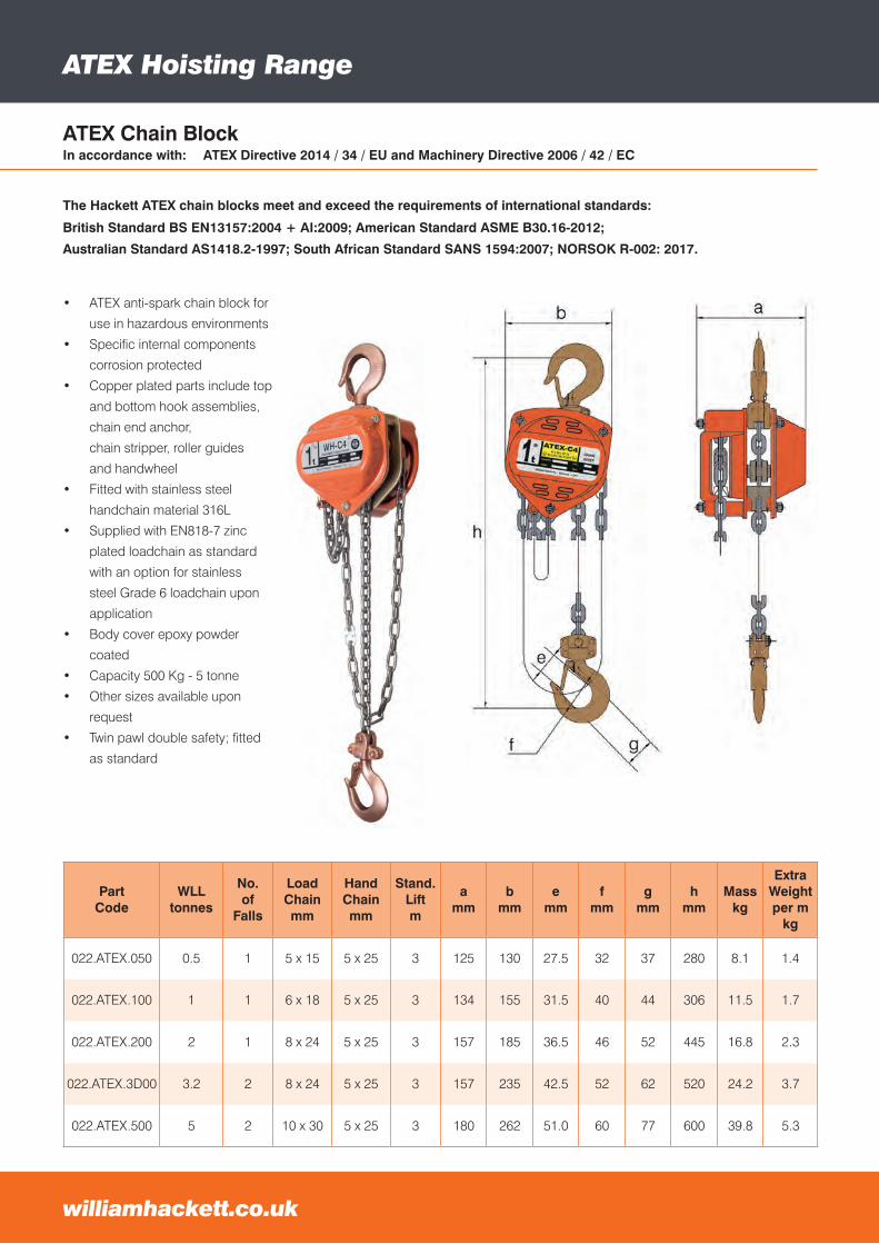
022.ATEX.050 0.5 1 5 x 15 5 x 25 3 125 130 27.5 32 37 280 8.1 1.4
022.ATEX.100 1 1 6 x 18 5 x 25 3 134 155 31.5 40 44 306 11.5 1.7
022.ATEX.200 2 1 8 x 24 5 x 25 3 157 185 36.5 46 52 445 16.8 2.3
022.ATEX.3D00 3.2 2 8 x 24 5 x 25 3 157 235 42.5 52 62 520 24.2 3.7
022.ATEX.500 5 2 10 x 30 5 x 25 3 180 262 51.0 60 77 600 39.8 5.3
• ATEX anti-spark chain block for
use in hazardous environments
• Specific internal components
corrosion protected
• Copper plated parts include top
and bottom hook assemblies,
chain end anchor,
chain stripper, roller guides
and handwheel
• Fitted with stainless steel
handchain material 316L
• Supplied with EN818-7 zinc
plated loadchain as standard
with an option for stainless
steel Grade 6 loadchain upon
application
• Body cover epoxy powder
coated
• Capacity 500 Kg - 5 tonne
• Other sizes available upon
request
• Twin pawl double safety; fitted
as standard
ATEX Chain BlockIn accordance with: ATEX Directive 2014 / 34 / EU and Machinery Directive 2006 / 42 / EC
The Hackett ATEX chain blocks meet and exceed the requirements of international standards:
British Standard BS EN13157:2004 + AI:2009; American Standard ASME B30.16-2012;
Australian Standard AS1418.2-1997; South African Standard SANS 1594:2007; NORSOK R-002: 2017.
47e: [email protected]: 01665 604200 f: 01665 604204
Part Code
WLLtonnes
No.of
Falls
Load Chainmm
Stand.Lift(m)
amm
bmm
cmm
dmm
emm
hmm
Masskg
Extra Weightper m
kg
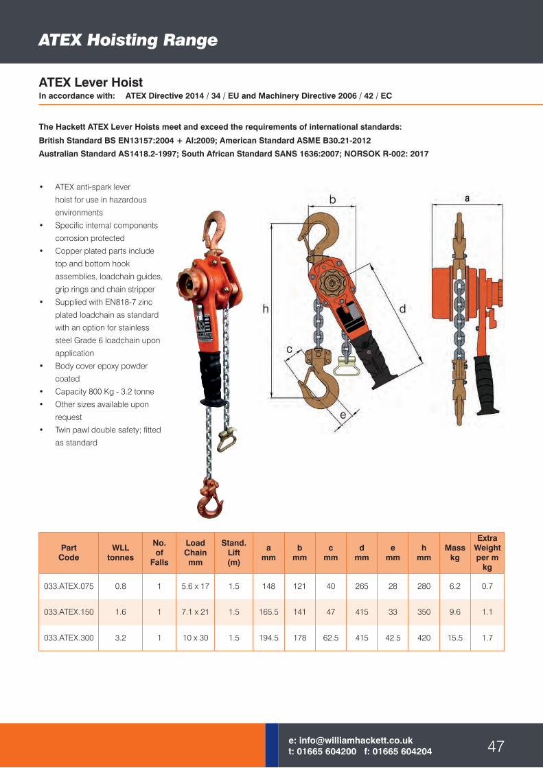
033.ATEX.075 0.8 1 5.6 x 17 1.5 148 121 40 265 28 280 6.2 0.7
033.ATEX.150 1.6 1 7.1 x 21 1.5 165.5 141 47 415 33 350 9.6 1.1
033.ATEX.300 3.2 1 10 x 30 1.5 194.5 178 62.5 415 42.5 420 15.5 1.7
• ATEX anti-spark lever
hoist for use in hazardous
environments
• Specific internal components
corrosion protected
• Copper plated parts include
top and bottom hook
assemblies, loadchain guides,
grip rings and chain stripper
• Supplied with EN818-7 zinc
plated loadchain as standard
with an option for stainless
steel Grade 6 loadchain upon
application
• Body cover epoxy powder
coated
• Capacity 800 Kg - 3.2 tonne
• Other sizes available upon
request
• Twin pawl double safety; fitted
as standard
ATEX Hoisting Range
ATEX Lever HoistIn accordance with: ATEX Directive 2014 / 34 / EU and Machinery Directive 2006 / 42 / EC
The Hackett ATEX Lever Hoists meet and exceed the requirements of international standards:
British Standard BS EN13157:2004 + AI:2009; American Standard ASME B30.21-2012
Australian Standard AS1418.2-1997; South African Standard SANS 1636:2007; NORSOK R-002: 2017
ATEX Trollies
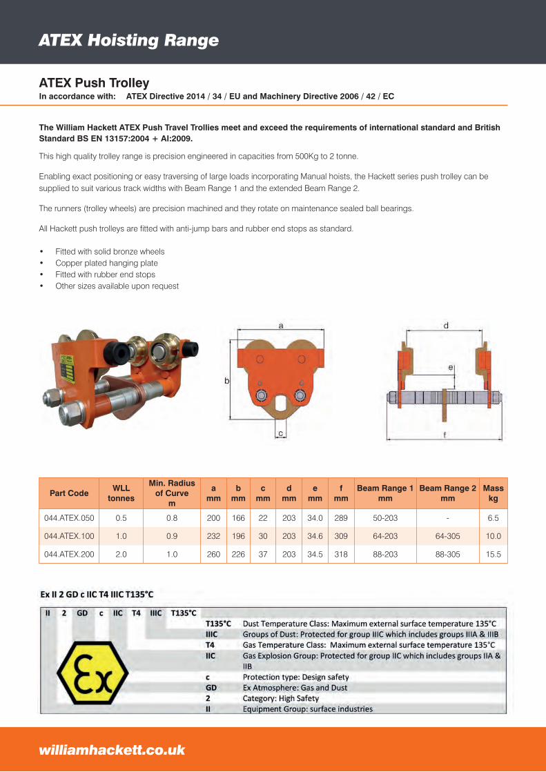
Part CodeWLL
tonnes
Min. Radiusof Curve
m
amm
bmm
cmm
dmm
emm
fmm
Beam Range 1 mm
Beam Range 2 mm
Mass kg
044.ATEX.050 0.5 0.8 200 166 22 203 34.0 289 50-203 - 6.5
044.ATEX.100 1.0 0.9 232 196 30 203 34.6 309 64-203 64-305 10.0
044.ATEX.200 2.0 1.0 260 226 37 203 34.5 318 88-203 88-305 15.5
This high quality trolley range is precision engineered in capacities from 500Kg to 2 tonne.
Enabling exact positioning or easy traversing of large loads incorporating Manual hoists, the Hackett series push trolley can be supplied to suit various track widths with Beam Range 1 and the extended Beam Range 2.
The runners (trolley wheels) are precision machined and they rotate on maintenance sealed ball bearings.
All Hackett push trolleys are fitted with anti-jump bars and rubber end stops as standard.
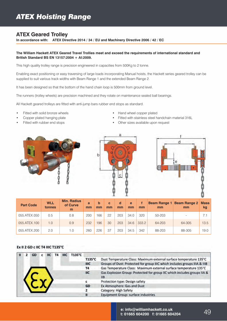
• Fitted with solid bronze wheels• Copper plated hanging plate• Fitted with rubber end stops• Other sizes available upon request
williamhackett.co.uk
ATEX Hoisting Range
ATEX Push TrolleyIn accordance with: ATEX Directive 2014 / 34 / EU and Machinery Directive 2006 / 42 / EC
The William Hackett ATEX Push Travel Trollies meet and exceed the requirements of international standard and British Standard BS EN 13157:2004 + AI:2009.
Part CodeWLL
tonnes
Min. Radiusof Curve
m
amm
bmm
cmm
dmm
emm
fmm
Beam Range 1 mm
Beam Range 2 mm
Mass kg
055.ATEX.050 0.5 0.8 200 166 22 203 34.0 320 50-203 - 7.1
055.ATEX.100 1.0 0.9 232 196 30 203 34.6 333.2 64-203 64-305 13.5
055.ATEX.200 2.0 1.0 260 226 37 203 34.5 342 88-203 88-305 19.0
• Fitted with solid bronze wheels • Hand wheel copper plated• Copper plated hanging plate • Fitted with stainless steel handchain material 316L• Fitted with rubber end stops • Other sizes available upon request
49e: [email protected]: 01665 604200 f: 01665 604204
ATEX Hoisting Range
ATEX Geared TrolleyIn accordance with: ATEX Directive 2014 / 34 / EU and Machinery Directive 2006 / 42 / EC
This high quality trolley range is precision engineered in capacities from 500Kg to 2 tonne.
Enabling exact positioning or easy traversing of large loads incorporating Manual hoists, the Hackett series geared trolley can be supplied to suit various track widths with Beam Range 1 and the extended Beam Range 2.
It has been designed so that the bottom of the hand chain loop is 500mm from ground level.
The runners (trolley wheels) are precision machined and they rotate on maintenance sealed ball bearings.
All Hackett geared trolleys are fitted with anti-jump bars rubber end stops as standard.
The William Hackett ATEX Geared Travel Trollies meet and exceed the requirements of international standard and British Standard BS EN 13157:2004 + AI:2009.
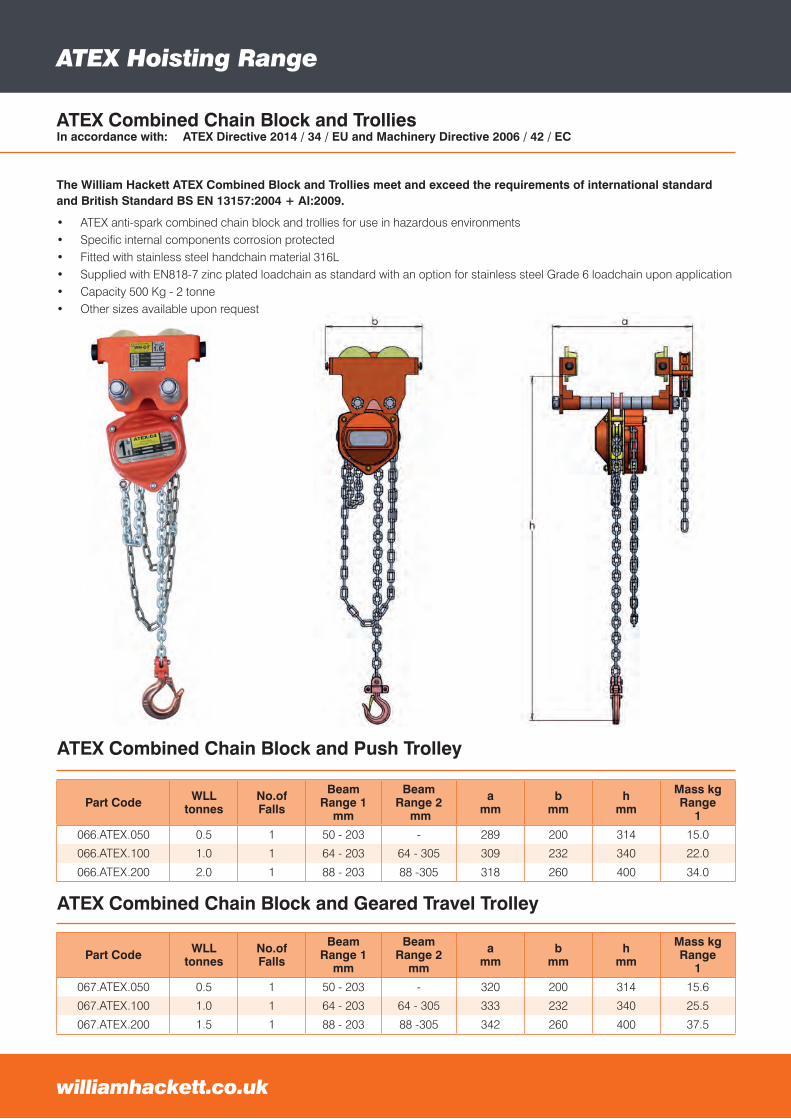
ATEX Combined Chain Block and TrolliesIn accordance with: ATEX Directive 2014 / 34 / EU and Machinery Directive 2006 / 42 / EC
ATEX TrolliesATEX Hoisting Range
williamhackett.co.uk
• ATEX anti-spark combined chain block and trollies for use in hazardous environments• Specific internal components corrosion protected• Fitted with stainless steel handchain material 316L• Supplied with EN818-7 zinc plated loadchain as standard with an option for stainless steel Grade 6 loadchain upon application• Capacity 500 Kg - 2 tonne• Other sizes available upon request
ATEX Combined Chain Block and Geared Travel Trolley
Part Code WLLtonnes
No.ofFalls
BeamRange 1
mm
BeamRange 2
mm
amm
bmm
hmm
Mass kgRange
1
066.ATEX.050 0.5 1 50 - 203 - 289 200 314 15.0
066.ATEX.100 1.0 1 64 - 203 64 - 305 309 232 340 22.0
066.ATEX.200 2.0 1 88 - 203 88 -305 318 260 400 34.0
Part Code WLLtonnes
No.ofFalls
BeamRange 1
mm
BeamRange 2
mm
amm
bmm
hmm
Mass kgRange
1
067.ATEX.050 0.5 1 50 - 203 - 320 200 314 15.6
067.ATEX.100 1.0 1 64 - 203 64 - 305 333 232 340 25.5
067.ATEX.200 1.5 1 88 - 203 88 -305 342 260 400 37.5
ATEX Combined Chain Block and Push Trolley
The William Hackett ATEX Combined Block and Trollies meet and exceed the requirements of international standard and British Standard BS EN 13157:2004 + AI:2009.
Offshore and Subsea Equipment
williamhackett.co.uk
PartCode
Nom. Size mm
WLLtonnes
Amm
Bmm
Cmm
Dmm
Emm
Gmm
Hmm
Kmm
Rmm
Wmm
MassKg
8-809-19 19 7.0 91 41 18 22 32 46 150 104 32 33 1.7
8-809-26 26 12.5 118 54 23 29 41 61 194 140 35 44 3.8
8-809-32 32 18.0 148 64 30 36 51 68 238 172 38 54 6.7
8-809-38 38 30.0 176 80 35 45 64 89 289 216 45 60 12.5
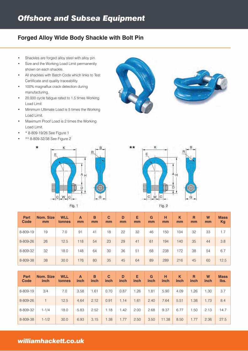
Forged Alloy Wide Body Shackle with Bolt Pin
• Shackles are forged alloy steel with alloy pin.
• Size and the Working Load Limit permanently
shown on each shackle.
• All shackles with Batch Code which links to Test
Certificate and quality traceability.
• 100% magnaflux crack detection during
manufacturing.
• 20,000 cycle fatigue rated to 1.5 times Working
Load Limit
• Minimum Ultimate Load is 5 times the Working
Load Limit.
• Maximum Proof Load is 2 times the Working
Load Limit.
• * 8-809-19/26 See Figure 1
• ** 8-809-32/38 See Figure 2
PartCode
Nom. Size inch
WLLtonnes
Ainch
Binch
Cinch
Dinch
Einch
Ginch
Hinch
Kinch
Rinch
Winch
Masslbs.
8-809-19 3/4 7.0 3.58 1.61 0.70 0.87 1.26 1.81 5.90 4.09 1.26 1.30 3.7
8-809-26 1 12.5 4.64 2.12 0.91 1.14 1.61 2.40 7.64 5.51 1.38 1.73 8.4
8-809-32 1-1/4 18.0 5.83 2.52 1.18 1.42 2.00 2.68 9.37 6.77 1.50 2.13 14.7
8-809-38 1-1/2 30.0 6.93 3.15 1.38 1.77 2.50 3.50 11.38 8.50 1.77 2.36 27.5
* **
PartCode Size WLL
tonnesA
mm E
mm H
mm O
mm P
mm Q
mm S
mmT
mmW
mmMass
Kg
8-911-22 22 6.5 86 58 148 50 63 30 19 10 38 1.8
8-911-26 26 8.5 96 69 166 50 65 30 20 10 44 2.5
8-911-28 28 9.5 111 74 190 70 88 35 21 12 46 3.6
8-911-32 32 12.0 121 84 210 70 88 35 25 12 54 4.8
8-911-36 36 13.5 134 92 232 75 96 40 27 15 59 6.8
8-911-38 38 17.0 146 99 254 75 98 40 27 15 60 8.3
8-911-45 45 25.0 178 127 313 90 114 50 30 20 73 16.6
8-911-50 50 35.0 197 146 347 106 132 60 30 20 83 23.4
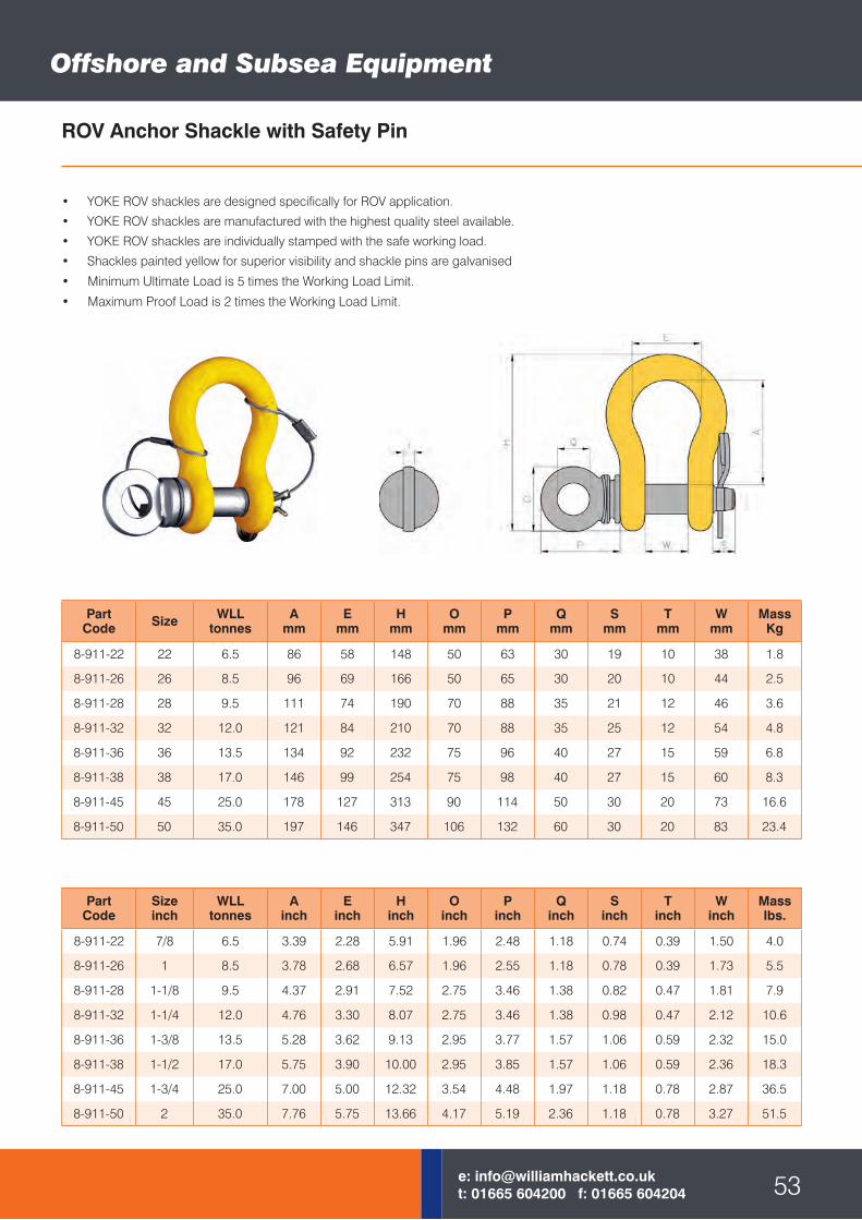
ROV Anchor Shackle with Safety Pin
• YOKE ROV shackles are designed specifically for ROV application.
• YOKE ROV shackles are manufactured with the highest quality steel available.
• YOKE ROV shackles are individually stamped with the safe working load.
• Shackles painted yellow for superior visibility and shackle pins are galvanised
• Minimum Ultimate Load is 5 times the Working Load Limit.
• Maximum Proof Load is 2 times the Working Load Limit.
Offshore and Subsea Equipment
53e: [email protected]: 01665 604200 f: 01665 604204
PartCode
Sizeinch
WLLtonnes
Ainch
Einch
Hinch
Oinch
Pinch
Qinch
Sinch
Tinch
Winch
Masslbs.
8-911-22 7/8 6.5 3.39 2.28 5.91 1.96 2.48 1.18 0.74 0.39 1.50 4.0
8-911-26 1 8.5 3.78 2.68 6.57 1.96 2.55 1.18 0.78 0.39 1.73 5.5
8-911-28 1-1/8 9.5 4.37 2.91 7.52 2.75 3.46 1.38 0.82 0.47 1.81 7.9
8-911-32 1-1/4 12.0 4.76 3.30 8.07 2.75 3.46 1.38 0.98 0.47 2.12 10.6
8-911-36 1-3/8 13.5 5.28 3.62 9.13 2.95 3.77 1.57 1.06 0.59 2.32 15.0
8-911-38 1-1/2 17.0 5.75 3.90 10.00 2.95 3.85 1.57 1.06 0.59 2.36 18.3
8-911-45 1-3/4 25.0 7.00 5.00 12.32 3.54 4.48 1.97 1.18 0.78 2.87 36.5
8-911-50 2 35.0 7.76 5.75 13.66 4.17 5.19 2.36 1.18 0.78 3.27 51.5
Offshore and Subsea Equipment
williamhackett.co.uk
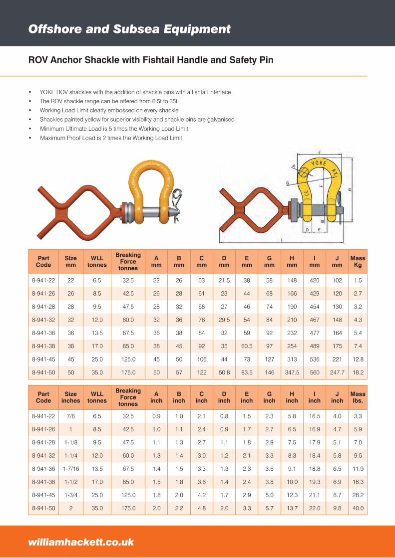
ROV Anchor Shackle with Fishtail Handle and Safety Pin
PartCode
Sizeinches
WLLtonnes
Breaking Forcetonnes
Ainch
Binch
Cinch
Dinch
Einch
Ginch
Hinch
Iinch
Jinch
Masslbs.
8-941-22 7/8 6.5 32.5 0.9 1.0 2.1 0.8 1.5 2.3 5.8 16.5 4.0 3.3
8-941-26 1 8.5 42.5 1.0 1.1 2.4 0.9 1.7 2.7 6.5 16.9 4.7 5.9
8-941-28 1-1/8 9.5 47.5 1.1 1.3 2.7 1.1 1.8 2.9 7.5 17.9 5.1 7.0
8-941-32 1-1/4 12.0 60.0 1.3 1.4 3.0 1.2 2.1 3.3 8.3 18.4 5.8 9.5
8-941-36 1-7/16 13.5 67.5 1.4 1.5 3.3 1.3 2.3 3.6 9.1 18.8 6.5 11.9
8-941-38 1-1/2 17.0 85.0 1.5 1.8 3.6 1.4 2.4 3.8 10.0 19.3 6.9 16.3
8-941-45 1-3/4 25.0 125.0 1.8 2.0 4.2 1.7 2.9 5.0 12.3 21.1 8.7 28.2
8-941-50 2 35.0 175.0 2.0 2.2 4.8 2.0 3.3 5.7 13.7 22.0 9.8 40.0
PartCode
Sizemm
WLLtonnes
Breaking Forcetonnes
Amm
Bmm
Cmm
Dmm
Emm
Gmm
Hmm
Imm
Jmm
MassKg
8-941-22 22 6.5 32.5 22 26 53 21.5 38 58 148 420 102 1.5
8-941-26 26 8.5 42.5 26 28 61 23 44 68 166 429 120 2.7
8-941-28 28 9.5 47.5 28 32 68 27 46 74 190 454 130 3.2
8-941-32 32 12.0 60.0 32 36 76 29.5 54 84 210 467 148 4.3
8-941-36 36 13.5 67.5 36 38 84 32 59 92 232 477 164 5.4
8-941-38 38 17.0 85.0 38 45 92 35 60.5 97 254 489 175 7.4
8-941-45 45 25.0 125.0 45 50 106 44 73 127 313 536 221 12.8
8-941-50 50 35.0 175.0 50 57 122 50.8 83.5 146 347.5 560 247.7 18.2
• YOKE ROV shackles with the addition of shackle pins with a fishtail interface.
• The ROV shackle range can be offered from 6.5t to 35t
• Working Load Limit clearly embossed on every shackle
• Shackles painted yellow for superior visibility and shackle pins are galvanised
• Minimum Ultimate Load is 5 times the Working Load Limit
• Maximum Proof Load is 2 times the Working Load Limit
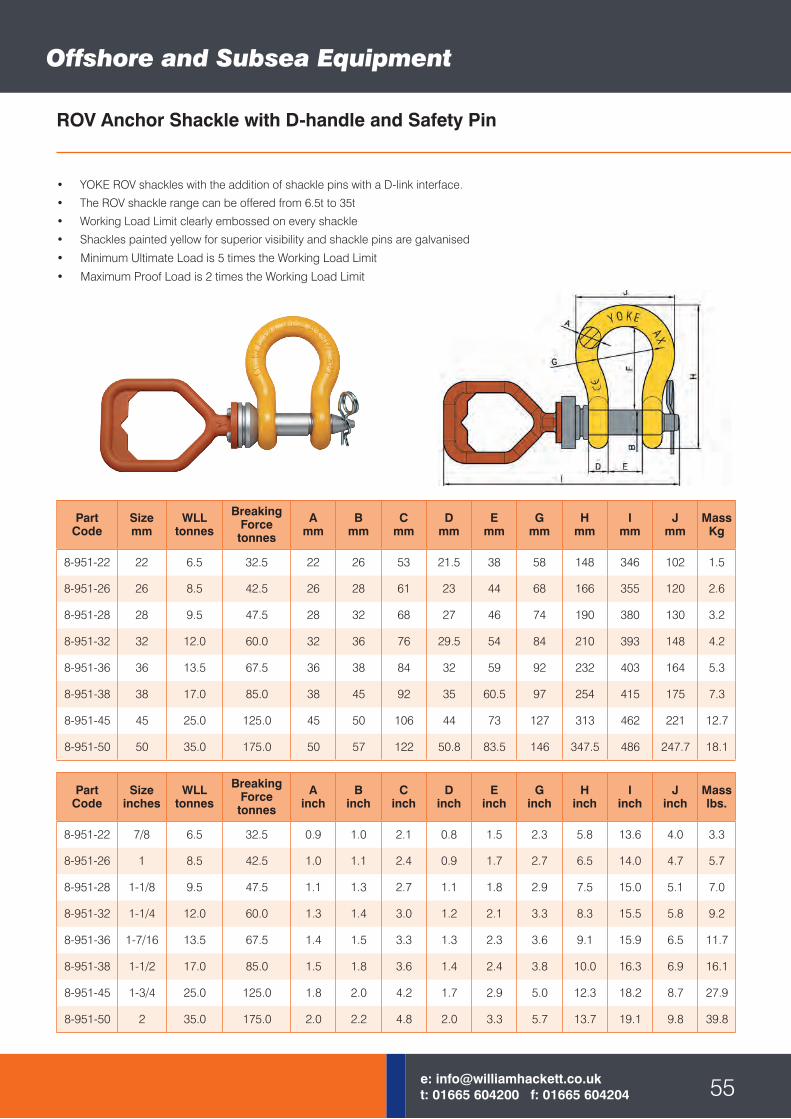
ROV Anchor Shackle with D-handle and Safety Pin
PartCode
Sizeinches
WLLtonnes
Breaking Forcetonnes
Ainch
Binch
Cinch
Dinch
Einch
Ginch
Hinch
Iinch
Jinch
Masslbs.
8-951-22 7/8 6.5 32.5 0.9 1.0 2.1 0.8 1.5 2.3 5.8 13.6 4.0 3.3
8-951-26 1 8.5 42.5 1.0 1.1 2.4 0.9 1.7 2.7 6.5 14.0 4.7 5.7
8-951-28 1-1/8 9.5 47.5 1.1 1.3 2.7 1.1 1.8 2.9 7.5 15.0 5.1 7.0
8-951-32 1-1/4 12.0 60.0 1.3 1.4 3.0 1.2 2.1 3.3 8.3 15.5 5.8 9.2
8-951-36 1-7/16 13.5 67.5 1.4 1.5 3.3 1.3 2.3 3.6 9.1 15.9 6.5 11.7
8-951-38 1-1/2 17.0 85.0 1.5 1.8 3.6 1.4 2.4 3.8 10.0 16.3 6.9 16.1
8-951-45 1-3/4 25.0 125.0 1.8 2.0 4.2 1.7 2.9 5.0 12.3 18.2 8.7 27.9
8-951-50 2 35.0 175.0 2.0 2.2 4.8 2.0 3.3 5.7 13.7 19.1 9.8 39.8
PartCode
Sizemm
WLLtonnes
Breaking Forcetonnes
Amm
Bmm
Cmm
Dmm
Emm
Gmm
Hmm
Imm
Jmm
MassKg
8-951-22 22 6.5 32.5 22 26 53 21.5 38 58 148 346 102 1.5
8-951-26 26 8.5 42.5 26 28 61 23 44 68 166 355 120 2.6
8-951-28 28 9.5 47.5 28 32 68 27 46 74 190 380 130 3.2
8-951-32 32 12.0 60.0 32 36 76 29.5 54 84 210 393 148 4.2
8-951-36 36 13.5 67.5 36 38 84 32 59 92 232 403 164 5.3
8-951-38 38 17.0 85.0 38 45 92 35 60.5 97 254 415 175 7.3
8-951-45 45 25.0 125.0 45 50 106 44 73 127 313 462 221 12.7
8-951-50 50 35.0 175.0 50 57 122 50.8 83.5 146 347.5 486 247.7 18.1
• YOKE ROV shackles with the addition of shackle pins with a D-link interface.
• The ROV shackle range can be offered from 6.5t to 35t
• Working Load Limit clearly embossed on every shackle
• Shackles painted yellow for superior visibility and shackle pins are galvanised
• Minimum Ultimate Load is 5 times the Working Load Limit
• Maximum Proof Load is 2 times the Working Load Limit
55e: [email protected]: 01665 604200 f: 01665 604204
Offshore and Subsea Equipment
Offshore and Subsea Equipment
PartCode
WLLtonnes
Amm
Dmm
dmm
Emm
Hmm
Kmm
Pmm
Rmm
Tmm
MassKg
8-921-03 3.0 32 25 15 20 29 122 25 8 24 1.0
8-921-05 5.4 40 31 18 20 37 149 31 8 31 2.1
8-921-07 7.0 51 39 24 20 46 192 39 8 37 4.0
8-921-11 11.0 62 57 28 30 58 232 57 8 48 7.0
8-921-15 15.0 72 62 32 30 66 256 62 8 56 9.4
8-921-22 22.0 90 81 40 50 77 318 81 10 68 18.6
8-921-30 30.0 90 83 45 50 92 357 83 10 76 31.2
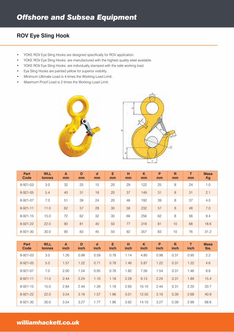
ROV Eye Sling Hook
• YOKE ROV Eye Sling Hooks are designed specifically for ROV application.
• YOKE ROV Eye Sling Hooks are manufactured with the highest quality steel available.
• YOKE ROV Eye Sling Hooks are individually stamped with the safe working load.
• Eye Sling Hooks are painted yellow for superior visibility.
• Minimum Ultimate Load is 4 times the Working Load Limit.
• Maximum Proof Load is 2 times the Working Load Limit.
williamhackett.co.uk
PartCode
WLLtonnes
Ainch
Dinch
dinch
Einch
Hinch
Kinch
Pinch
Rinch
Tinch
Masslbs.
8-921-03 3.0 1.26 0.98 0.59 0.78 1.14 4.80 0.98 0.31 0.95 2.2
8-921-05 5.0 1.57 1.22 0.71 0.78 1.46 5.87 1.22 0.31 1.22 4.6
8-921-07 7.0 2.00 1.54 0.95 0.78 1.82 7.56 1.54 0.31 1.46 8.8
8-921-11 11.0 2.44 2.24 1.10 1.18 2.28 9.13 2.24 0.31 1.89 15.4
8-921-15 15.0 2.84 2.44 1.26 1.18 2.60 10.10 2.44 0.31 2.20 20.7
8-921-22 22.0 3.54 3.19 1.57 1.96 3.01 12.50 3.19 0.39 2.68 40.9
8-921-30 30.0 3.54 3.27 1.77 1.96 3.62 14.10 3.27 0.39 2.99 68.6
PartCode
WLLtonnes
Amm
Cmm
Emm
Gmm
Hmm
Lmm
Nmm
Pmm
Qmm
Rmm
Tmm
MassKg
8-931-05 5.4 55 38 20 130 37 404 28 32 32 8 33 6.0
8-931-08 8.0 55 49 20 166 46 427 28 39 32 8 42 7.6
8-931-11 11.5 65 62 30 196 58 569 40 57 50 8 48 13.9
8-931-16 16.0 65 65 30 221 66 586 40 62 50 8 56 15.9
8-931-22 22.0 85 71 50 277 77 685 52 81 65 10 68 31.0
8-931-32 31.5 85 87 50 353 92 728 52 88 65 10 76 44.6
ROV Shank Hook
• YOKE ROV Shank Hooks are designed specifically for ROV application.
• YOKE ROV Shank Hooks are manufactured with the highest quality steel available.
• YOKE ROV Shank Hooks are individually stamped with the safe working load.
• Shank Hooks are painted yellow for superior visibility.
• Minimum Ultimate Load is 4 times the Working Load Limit.
• Maximum Proof Load is 2 times the Working Load Limit.
57e: [email protected]: 01665 604200 f: 01665 604204
PartCode
WLLtonnes
Ainch
Cinch
Einch
Ginch
Hinch
Linch
Ninch
Pinch
Qinch
Rinch
Tinch
Masslbs.
8-931-05 5.4 2.16 1.53 0.78 5.12 1.46 15.90 1.10 1.26 1.25 0.31 1.31 13.2
8-931-08 8.0 2.16 1.94 0.78 6.54 1.82 16.81 1.10 1.54 1.25 0.31 1.66 16.7
8-931-11 11.5 2.56 2.46 1.18 7.72 2.28 22.40 1.57 2.24 1.96 0.31 1.88 30.6
8-931-16 16.0 2.56 2.59 1.18 8.70 2.60 23.07 1.57 2.44 1.96 0.31 2.19 35.0
8-931-22 22.0 3.35 2.81 1.96 10.91 3.01 26.96 2.04 3.19 2.55 0.39 2.69 68.2
8-931-32 31.5 3.35 3.44 1.96 13.90 3.62 28.66 2.04 3.46 2.55 0.39 3.00 98.1
Offshore and Subsea Equipment
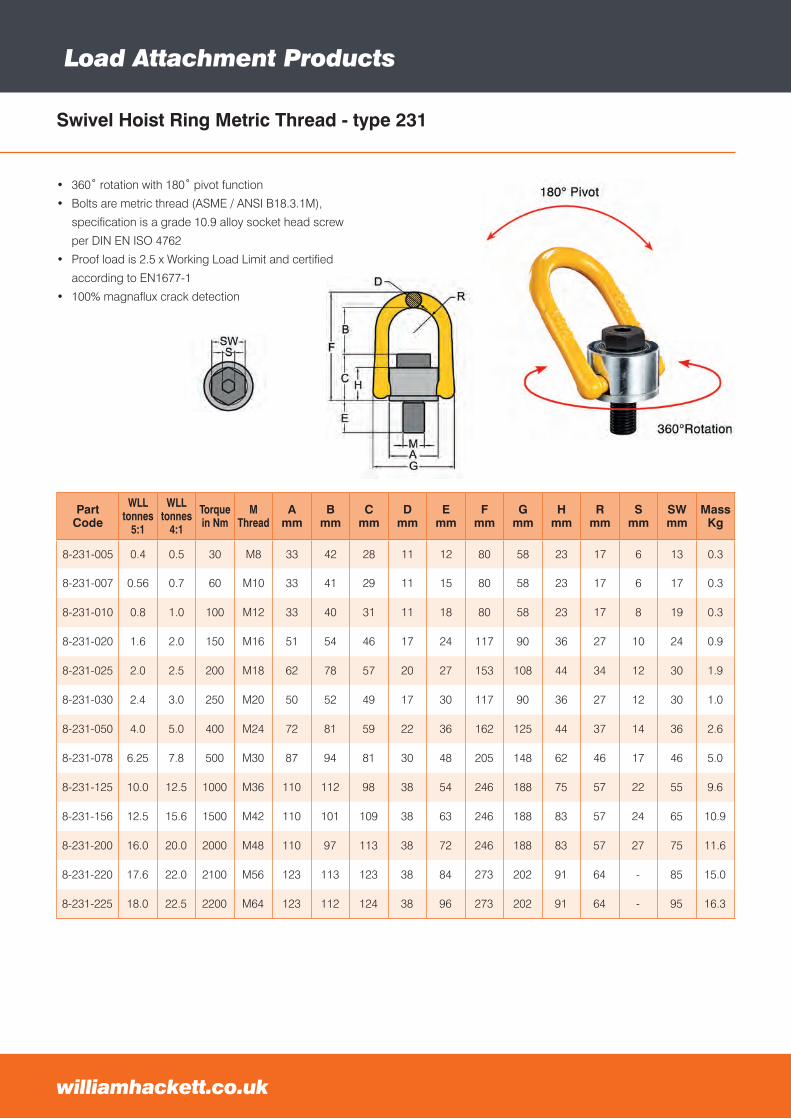
williamhackett.co.uk
Load Attachment Products
PartCode
WLLtonnes
5:1
WLLtonnes
4:1
Torquein Nm
MThread
Amm
Bmm
Cmm
Dmm
Emm
Fmm
Gmm
Hmm
Rmm
Smm
SWmm
MassKg
8-231-005 0.4 0.5 30 M8 33 42 28 11 12 80 58 23 17 6 13 0.3
8-231-007 0.56 0.7 60 M10 33 41 29 11 15 80 58 23 17 6 17 0.3
8-231-010 0.8 1.0 100 M12 33 40 31 11 18 80 58 23 17 8 19 0.3
8-231-020 1.6 2.0 150 M16 51 54 46 17 24 117 90 36 27 10 24 0.9
8-231-025 2.0 2.5 200 M18 62 78 57 20 27 153 108 44 34 12 30 1.9
8-231-030 2.4 3.0 250 M20 50 52 49 17 30 117 90 36 27 12 30 1.0
8-231-050 4.0 5.0 400 M24 72 81 59 22 36 162 125 44 37 14 36 2.6
8-231-078 6.25 7.8 500 M30 87 94 81 30 48 205 148 62 46 17 46 5.0
8-231-125 10.0 12.5 1000 M36 110 112 98 38 54 246 188 75 57 22 55 9.6
8-231-156 12.5 15.6 1500 M42 110 101 109 38 63 246 188 83 57 24 65 10.9
8-231-200 16.0 20.0 2000 M48 110 97 113 38 72 246 188 83 57 27 75 11.6
8-231-220 17.6 22.0 2100 M56 123 113 123 38 84 273 202 91 64 - 85 15.0
8-231-225 18.0 22.5 2200 M64 123 112 124 38 96 273 202 91 64 - 95 16.3
Swivel Hoist Ring Metric Thread - type 231
• 360˚ rotation with 180˚ pivot function
• Bolts are metric thread (ASME / ANSI B18.3.1M),
specification is a grade 10.9 alloy socket head screw
per DIN EN ISO 4762
• Proof load is 2.5 x Working Load Limit and certified
according to EN1677-1
• 100% magnaflux crack detection
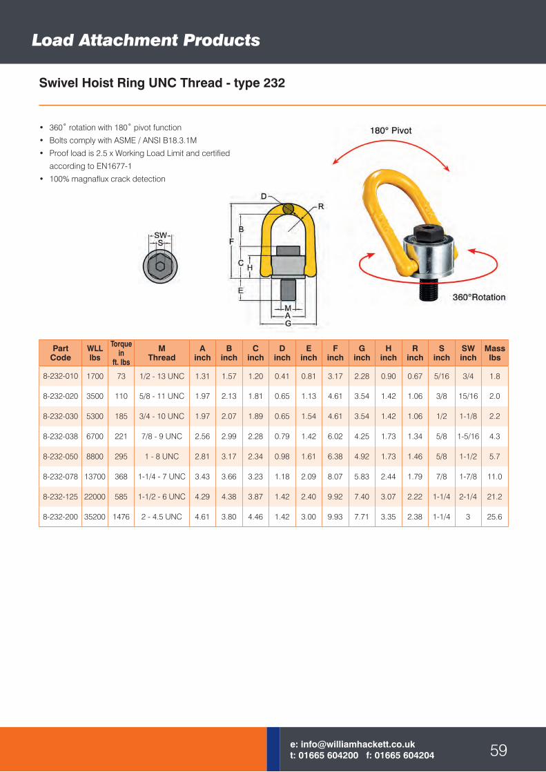
PartCode
WLLlbs
Torquein
ft. lbs
MThread
Ainch
Binch
Cinch
Dinch
Einch
Finch
Ginch
Hinch
Rinch
Sinch
SWinch
Masslbs
8-232-010 1700 73 1/2 - 13 UNC 1.31 1.57 1.20 0.41 0.81 3.17 2.28 0.90 0.67 5/16 3/4 1.8
8-232-020 3500 110 5/8 - 11 UNC 1.97 2.13 1.81 0.65 1.13 4.61 3.54 1.42 1.06 3/8 15/16 2.0
8-232-030 5300 185 3/4 - 10 UNC 1.97 2.07 1.89 0.65 1.54 4.61 3.54 1.42 1.06 1/2 1-1/8 2.2
8-232-038 6700 221 7/8 - 9 UNC 2.56 2.99 2.28 0.79 1.42 6.02 4.25 1.73 1.34 5/8 1-5/16 4.3
8-232-050 8800 295 1 - 8 UNC 2.81 3.17 2.34 0.98 1.61 6.38 4.92 1.73 1.46 5/8 1-1/2 5.7
8-232-078 13700 368 1-1/4 - 7 UNC 3.43 3.66 3.23 1.18 2.09 8.07 5.83 2.44 1.79 7/8 1-7/8 11.0
8-232-125 22000 585 1-1/2 - 6 UNC 4.29 4.38 3.87 1.42 2.40 9.92 7.40 3.07 2.22 1-1/4 2-1/4 21.2
8-232-200 35200 1476 2 - 4.5 UNC 4.61 3.80 4.46 1.42 3.00 9.93 7.71 3.35 2.38 1-1/4 3 25.6
Swivel Hoist Ring UNC Thread - type 232
• 360˚ rotation with 180˚ pivot function
• Bolts comply with ASME / ANSI B18.3.1M
• Proof load is 2.5 x Working Load Limit and certified
according to EN1677-1
• 100% magnaflux crack detection
59e: [email protected]: 01665 604200 f: 01665 604204
Load Attachment Products
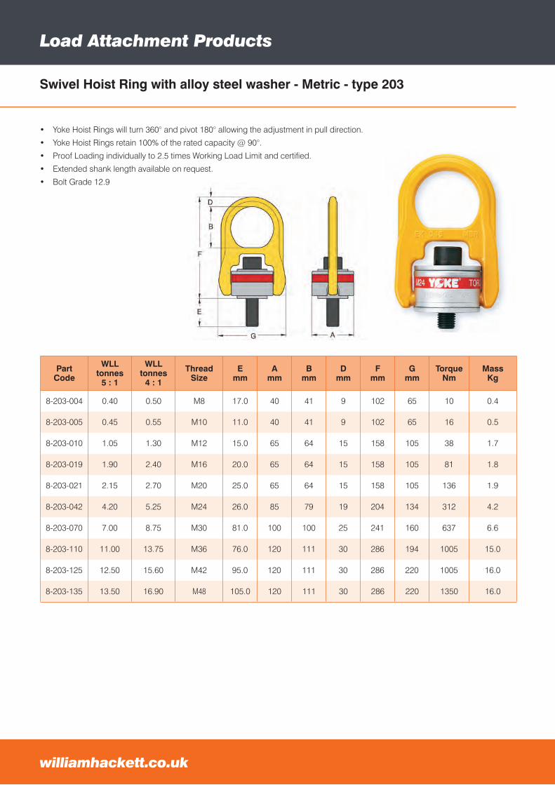
Load Attachment Products
PartCode
WLLtonnes
5 : 1
WLLtonnes
4 : 1
ThreadSize
Emm
Amm
Bmm
Dmm
Fmm
Gmm
TorqueNm
MassKg
8-203-004 0.40 0.50 M8 17.0 40 41 9 102 65 10 0.4
8-203-005 0.45 0.55 M10 11.0 40 41 9 102 65 16 0.5
8-203-010 1.05 1.30 M12 15.0 65 64 15 158 105 38 1.7
8-203-019 1.90 2.40 M16 20.0 65 64 15 158 105 81 1.8
8-203-021 2.15 2.70 M20 25.0 65 64 15 158 105 136 1.9
8-203-042 4.20 5.25 M24 26.0 85 79 19 204 134 312 4.2
8-203-070 7.00 8.75 M30 81.0 100 100 25 241 160 637 6.6
8-203-110 11.00 13.75 M36 76.0 120 111 30 286 194 1005 15.0
8-203-125 12.50 15.60 M42 95.0 120 111 30 286 220 1005 16.0
8-203-135 13.50 16.90 M48 105.0 120 111 30 286 220 1350 16.0
• Yoke Hoist Rings will turn 360° and pivot 180° allowing the adjustment in pull direction.
• Yoke Hoist Rings retain 100% of the rated capacity @ 90°.
• Proof Loading individually to 2.5 times Working Load Limit and certified.
• Extended shank length available on request.
• Bolt Grade 12.9
Swivel Hoist Ring with alloy steel washer - Metric - type 203
williamhackett.co.uk
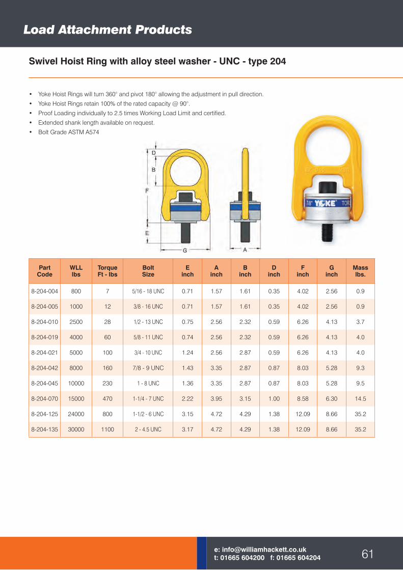
PartCode
WLLlbs
TorqueFt - lbs
BoltSize
Einch
Ainch
Binch
Dinch
Finch
Ginch
Masslbs.
8-204-004 800 7 5/16 - 18 UNC 0.71 1.57 1.61 0.35 4.02 2.56 0.9
8-204-005 1000 12 3/8 - 16 UNC 0.71 1.57 1.61 0.35 4.02 2.56 0.9
8-204-010 2500 28 1/2 - 13 UNC 0.75 2.56 2.32 0.59 6.26 4.13 3.7
8-204-019 4000 60 5/8 - 11 UNC 0.74 2.56 2.32 0.59 6.26 4.13 4.0
8-204-021 5000 100 3/4 - 10 UNC 1.24 2.56 2.87 0.59 6.26 4.13 4.0
8-204-042 8000 160 7/8 - 9 UNC 1.43 3.35 2.87 0.87 8.03 5.28 9.3
8-204-045 10000 230 1 - 8 UNC 1.36 3.35 2.87 0.87 8.03 5.28 9.5
8-204-070 15000 470 1-1/4 - 7 UNC 2.22 3.95 3.15 1.00 8.58 6.30 14.5
8-204-125 24000 800 1-1/2 - 6 UNC 3.15 4.72 4.29 1.38 12.09 8.66 35.2
8-204-135 30000 1100 2 - 4.5 UNC 3.17 4.72 4.29 1.38 12.09 8.66 35.2
• Yoke Hoist Rings will turn 360° and pivot 180° allowing the adjustment in pull direction.
• Yoke Hoist Rings retain 100% of the rated capacity @ 90°.
• Proof Loading individually to 2.5 times Working Load Limit and certified.
• Extended shank length available on request.
• Bolt Grade ASTM A574
Swivel Hoist Ring with alloy steel washer - UNC - type 204
61e: [email protected]: 01665 604200 f: 01665 604204
Load Attachment Products
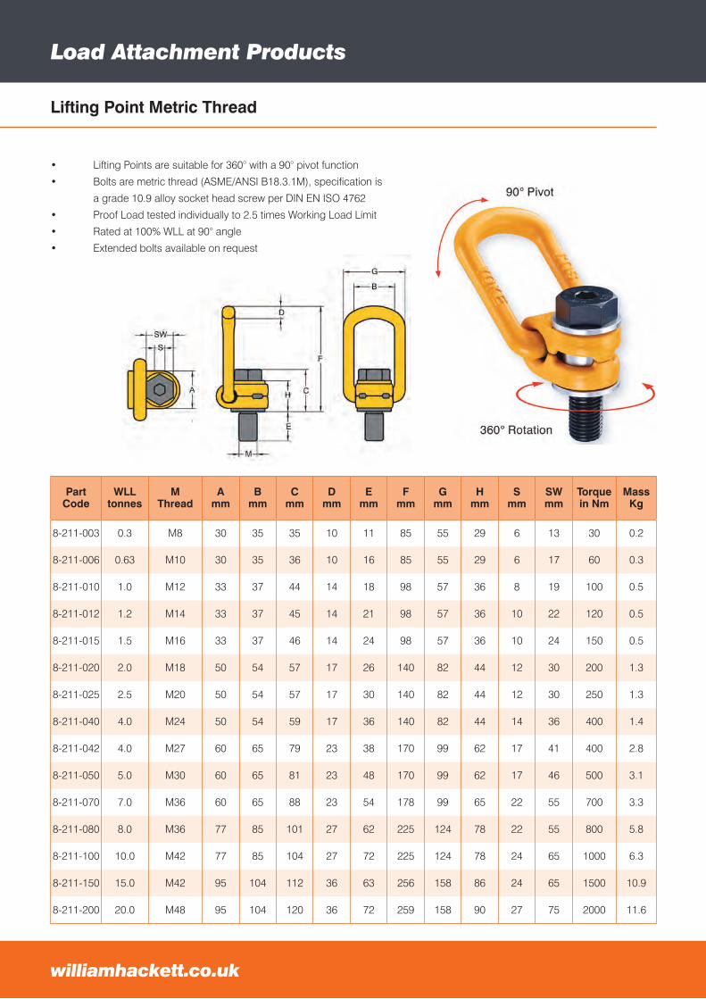
Load Attachment Products
williamhackett.co.uk
Part Code
WLLtonnes
M Thread
Amm
Bmm
Cmm
Dmm
Emm
Fmm
Gmm
Hmm
Smm
SWmm
Torquein Nm
MassKg
8-211-003 0.3 M8 30 35 35 10 11 85 55 29 6 13 30 0.2
8-211-006 0.63 M10 30 35 36 10 16 85 55 29 6 17 60 0.3
8-211-010 1.0 M12 33 37 44 14 18 98 57 36 8 19 100 0.5
8-211-012 1.2 M14 33 37 45 14 21 98 57 36 10 22 120 0.5
8-211-015 1.5 M16 33 37 46 14 24 98 57 36 10 24 150 0.5
8-211-020 2.0 M18 50 54 57 17 26 140 82 44 12 30 200 1.3
8-211-025 2.5 M20 50 54 57 17 30 140 82 44 12 30 250 1.3
8-211-040 4.0 M24 50 54 59 17 36 140 82 44 14 36 400 1.4
8-211-042 4.0 M27 60 65 79 23 38 170 99 62 17 41 400 2.8
8-211-050 5.0 M30 60 65 81 23 48 170 99 62 17 46 500 3.1
8-211-070 7.0 M36 60 65 88 23 54 178 99 65 22 55 700 3.3
8-211-080 8.0 M36 77 85 101 27 62 225 124 78 22 55 800 5.8
8-211-100 10.0 M42 77 85 104 27 72 225 124 78 24 65 1000 6.3
8-211-150 15.0 M42 95 104 112 36 63 256 158 86 24 65 1500 10.9
8-211-200 20.0 M48 95 104 120 36 72 259 158 90 27 75 2000 11.6
• Lifting Points are suitable for 360° with a 90° pivot function
• Bolts are metric thread (ASME/ANSI B18.3.1M), specification is
a grade 10.9 alloy socket head screw per DIN EN ISO 4762
• Proof Load tested individually to 2.5 times Working Load Limit
• Rated at 100% WLL at 90° angle
• Extended bolts available on request
Lifting Point Metric Thread
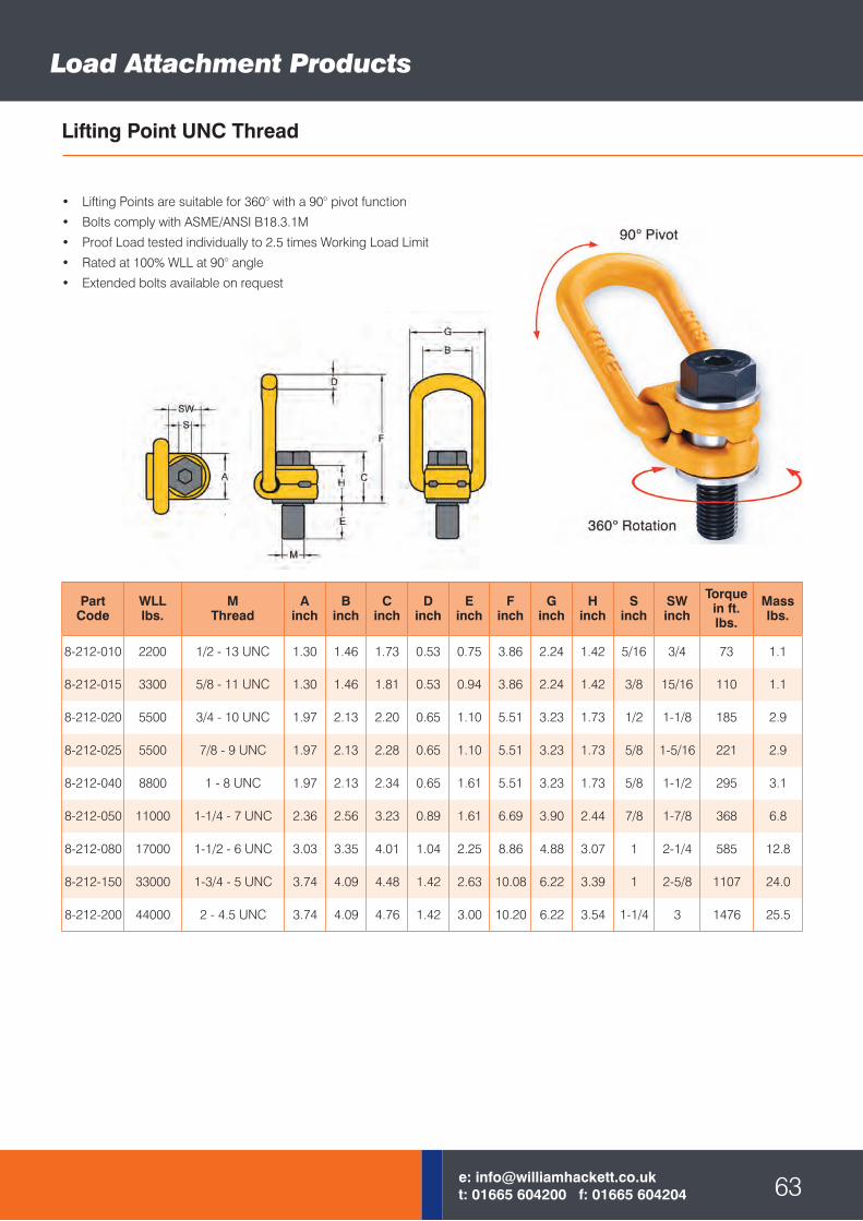
Load Attachment Products
63e: [email protected]: 01665 604200 f: 01665 604204
• Lifting Points are suitable for 360° with a 90° pivot function
• Bolts comply with ASME/ANSI B18.3.1M
• Proof Load tested individually to 2.5 times Working Load Limit
• Rated at 100% WLL at 90° angle
• Extended bolts available on request
Part Code
WLLlbs.
M Thread
Ainch
Binch
Cinch
Dinch
Einch
Finch
Ginch
Hinch
Sinch
SWinch
Torquein ft. lbs.
Masslbs.
8-212-010 2200 1/2 - 13 UNC 1.30 1.46 1.73 0.53 0.75 3.86 2.24 1.42 5/16 3/4 73 1.1
8-212-015 3300 5/8 - 11 UNC 1.30 1.46 1.81 0.53 0.94 3.86 2.24 1.42 3/8 15/16 110 1.1
8-212-020 5500 3/4 - 10 UNC 1.97 2.13 2.20 0.65 1.10 5.51 3.23 1.73 1/2 1-1/8 185 2.9
8-212-025 5500 7/8 - 9 UNC 1.97 2.13 2.28 0.65 1.10 5.51 3.23 1.73 5/8 1-5/16 221 2.9
8-212-040 8800 1 - 8 UNC 1.97 2.13 2.34 0.65 1.61 5.51 3.23 1.73 5/8 1-1/2 295 3.1
8-212-050 11000 1-1/4 - 7 UNC 2.36 2.56 3.23 0.89 1.61 6.69 3.90 2.44 7/8 1-7/8 368 6.8
8-212-080 17000 1-1/2 - 6 UNC 3.03 3.35 4.01 1.04 2.25 8.86 4.88 3.07 1 2-1/4 585 12.8
8-212-150 33000 1-3/4 - 5 UNC 3.74 4.09 4.48 1.42 2.63 10.08 6.22 3.39 1 2-5/8 1107 24.0
8-212-200 44000 2 - 4.5 UNC 3.74 4.09 4.76 1.42 3.00 10.20 6.22 3.54 1-1/4 3 1476 25.5
Lifting Point UNC Thread
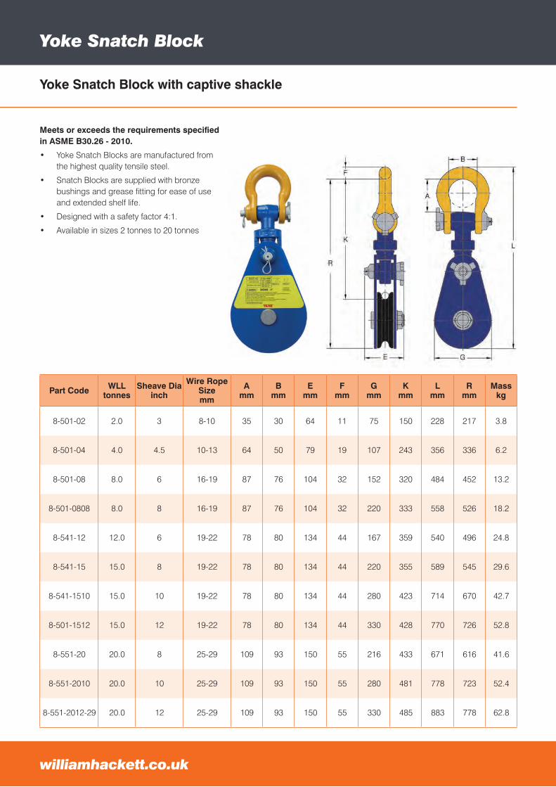
Meets or exceeds the requirements specified in ASME B30.26 - 2010.
• Yoke Snatch Blocks are manufactured from the highest quality tensile steel.
• Snatch Blocks are supplied with bronze bushings and grease fitting for ease of use and extended shelf life.
• Designed with a safety factor 4:1.
• Available in sizes 2 tonnes to 20 tonnes
Yoke Snatch Block
Part Code WLL tonnes
Sheave Diainch
Wire Rope Sizemm
Amm
Bmm
Emm
Fmm
Gmm
Kmm
Lmm
Rmm
Masskg
8-501-02 2.0 3 8-10 35 30 64 11 75 150 228 217 3.8
8-501-04 4.0 4.5 10-13 64 50 79 19 107 243 356 336 6.2
8-501-08 8.0 6 16-19 87 76 104 32 152 320 484 452 13.2
8-501-0808 8.0 8 16-19 87 76 104 32 220 333 558 526 18.2
8-541-12 12.0 6 19-22 78 80 134 44 167 359 540 496 24.8
8-541-15 15.0 8 19-22 78 80 134 44 220 355 589 545 29.6
8-541-1510 15.0 10 19-22 78 80 134 44 280 423 714 670 42.7
8-501-1512 15.0 12 19-22 78 80 134 44 330 428 770 726 52.8
8-551-20 20.0 8 25-29 109 93 150 55 216 433 671 616 41.6
8-551-2010 20.0 10 25-29 109 93 150 55 280 481 778 723 52.4
8-551-2012-29 20.0 12 25-29 109 93 150 55 330 485 883 778 62.8
williamhackett.co.uk
Yoke Snatch Block with captive shackle
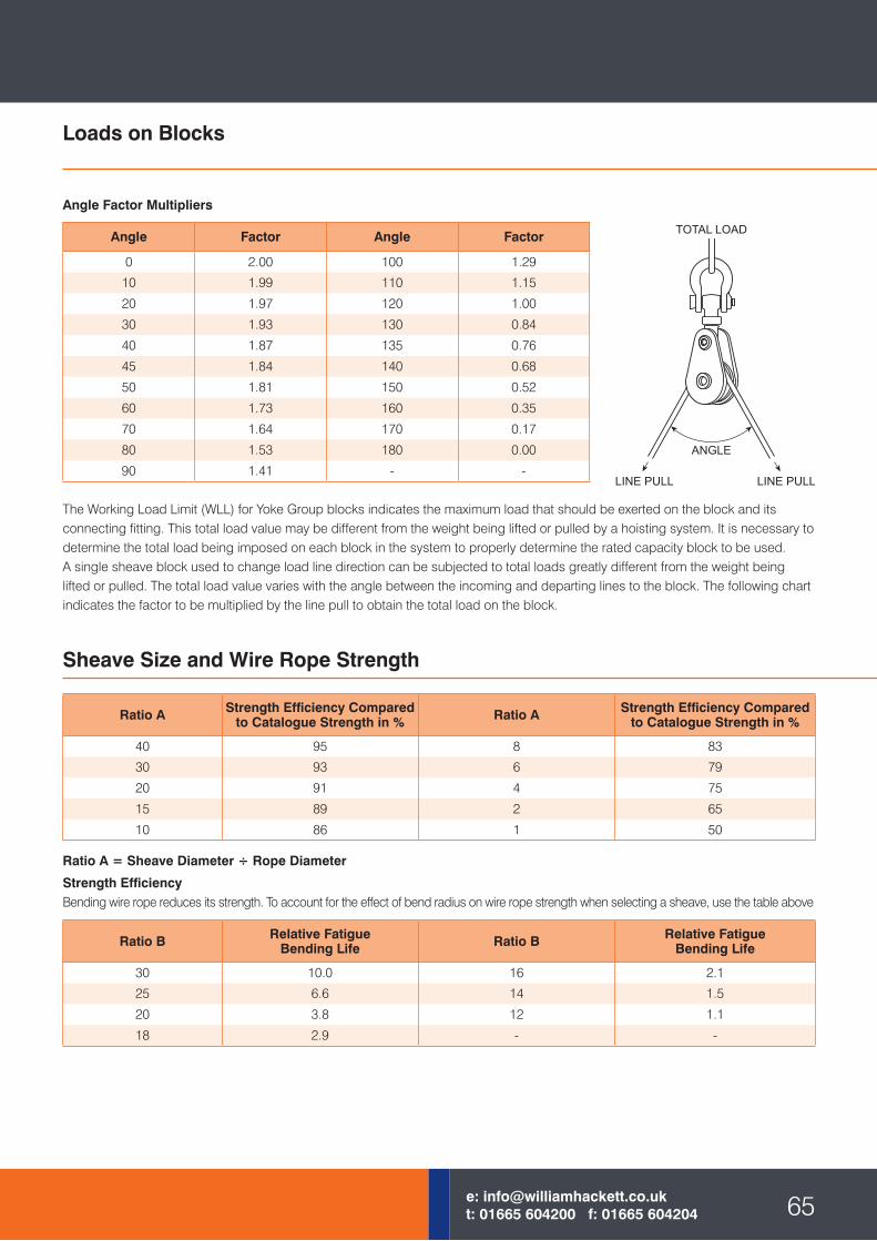
Loads on Blocks
The Working Load Limit (WLL) for Yoke Group blocks indicates the maximum load that should be exerted on the block and its connecting fitting. This total load value may be different from the weight being lifted or pulled by a hoisting system. It is necessary to determine the total load being imposed on each block in the system to properly determine the rated capacity block to be used.A single sheave block used to change load line direction can be subjected to total loads greatly different from the weight being lifted or pulled. The total load value varies with the angle between the incoming and departing lines to the block. The following chart indicates the factor to be multiplied by the line pull to obtain the total load on the block.
Ratio A = Sheave Diameter ÷ Rope Diameter
Strength EfficiencyBending wire rope reduces its strength. To account for the effect of bend radius on wire rope strength when selecting a sheave, use the table above
Angle Factor Multipliers
Angle Factor Angle Factor
0 2.00 100 1.29
10 1.99 110 1.15
20 1.97 120 1.00
30 1.93 130 0.84
40 1.87 135 0.76
45 1.84 140 0.68
50 1.81 150 0.52
60 1.73 160 0.35
70 1.64 170 0.17
80 1.53 180 0.00
90 1.41 - -
Sheave Size and Wire Rope Strength
Ratio A Strength Efficiency Compared to Catalogue Strength in % Ratio A Strength Efficiency Compared
to Catalogue Strength in %
40 95 8 83
30 93 6 79
20 91 4 75
15 89 2 65
10 86 1 50
Ratio B Relative FatigueBending Life Ratio B Relative Fatigue
Bending Life
30 10.0 16 2.1
25 6.6 14 1.5
20 3.8 12 1.1
18 2.9 - -
65e: [email protected]: 01665 604200 f: 01665 604204
LINE PULL LINE PULL
ANGLE
TOTAL LOAD
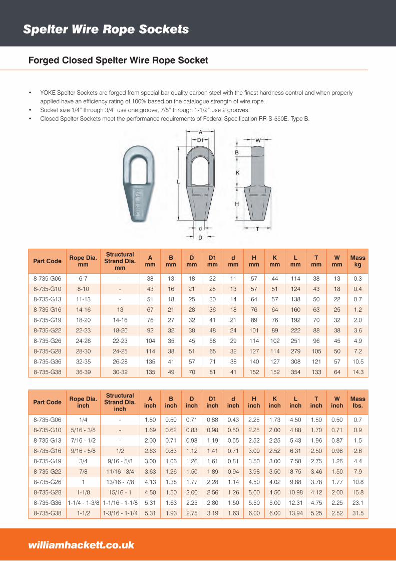
Spelter Wire Rope Sockets
Forged Closed Spelter Wire Rope Socket
Part Code Rope Dia.mm
StructuralStrand Dia.
mm
Amm
Bmm
Dmm
D1mm
dmm
Hmm
Kmm
Lmm
Tmm
Wmm
Masskg
8-735-G06 6-7 - 38 13 18 22 11 57 44 114 38 13 0.3
8-735-G10 8-10 - 43 16 21 25 13 57 51 124 43 18 0.4
8-735-G13 11-13 - 51 18 25 30 14 64 57 138 50 22 0.7
8-735-G16 14-16 13 67 21 28 36 18 76 64 160 63 25 1.2
8-735-G19 18-20 14-16 76 27 32 41 21 89 76 192 70 32 2.0
8-735-G22 22-23 18-20 92 32 38 48 24 101 89 222 88 38 3.6
8-735-G26 24-26 22-23 104 35 45 58 29 114 102 251 96 45 4.9
8-735-G28 28-30 24-25 114 38 51 65 32 127 114 279 105 50 7.2
8-735-G36 32-35 26-28 135 41 57 71 38 140 127 308 121 57 10.5
8-735-G38 36-39 30-32 135 49 70 81 41 152 152 354 133 64 14.3
66williamhackett.co.uk
• YOKE Spelter Sockets are forged from special bar quality carbon steel with the finest hardness control and when properly applied have an efficiency rating of 100% based on the catalogue strength of wire rope.
• Socket size 1/4” through 3/4” use one groove, 7/8” through 1-1/2” use 2 grooves.• Closed Spelter Sockets meet the performance requirements of Federal Specification RR-S-550E. Type B.
Part Code Rope Dia.inch
StructuralStrand Dia.
inch
Ainch
Binch
Dinch
D1inch
dinch
Hinch
Kinch
Linch
Tinch
Winch
Masslbs.
8-735-G06 1/4 - 1.50 0.50 0.71 0.88 0.43 2.25 1.73 4.50 1.50 0.50 0.7
8-735-G10 5/16 - 3/8 - 1.69 0.62 0.83 0.98 0.50 2.25 2.00 4.88 1.70 0.71 0.9
8-735-G13 7/16 - 1/2 - 2.00 0.71 0.98 1.19 0.55 2.52 2.25 5.43 1.96 0.87 1.5
8-735-G16 9/16 - 5/8 1/2 2.63 0.83 1.12 1.41 0.71 3.00 2.52 6.31 2.50 0.98 2.6
8-735-G19 3/4 9/16 - 5/8 3.00 1.06 1.26 1.61 0.81 3.50 3.00 7.58 2.75 1.26 4.4
8-735-G22 7/8 11/16 - 3/4 3.63 1.26 1.50 1.89 0.94 3.98 3.50 8.75 3.46 1.50 7.9
8-735-G26 1 13/16 - 7/8 4.13 1.38 1.77 2.28 1.14 4.50 4.02 9.88 3.78 1.77 10.8
8-735-G28 1-1/8 15/16 - 1 4.50 1.50 2.00 2.56 1.26 5.00 4.50 10.98 4.12 2.00 15.8
8-735-G36 1-1/4 - 1-3/8 1-1/16 - 1-1/8 5.31 1.63 2.25 2.80 1.50 5.50 5.00 12.31 4.75 2.25 23.1
8-735-G38 1-1/2 1-3/16 - 1-1/4 5.31 1.93 2.75 3.19 1.63 6.00 6.00 13.94 5.25 2.52 31.5
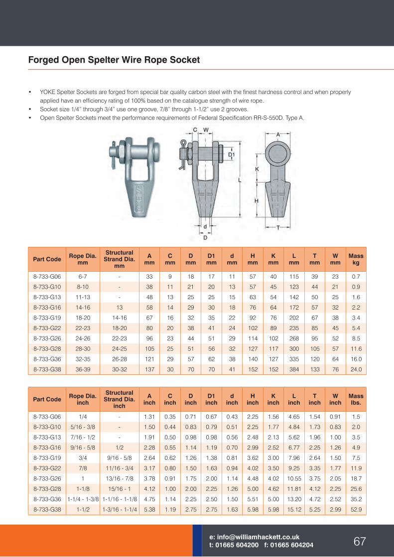
• YOKE Spelter Sockets are forged from special bar quality carbon steel with the finest hardness control and when properly applied have an efficiency rating of 100% based on the catalogue strength of wire rope.
• Socket size 1/4” through 3/4” use one groove, 7/8” through 1-1/2” use 2 grooves.• Open Spelter Sockets meet the performance requirements of Federal Specification RR-S-550D. Type A.
Forged Open Spelter Wire Rope Socket
Part Code Rope Dia.mm
StructuralStrand Dia.
mm
Amm
Cmm
Dmm
D1mm
dmm
Hmm
Kmm
Lmm
Tmm
Wmm
Masskg
8-733-G06 6-7 - 33 9 18 17 11 57 40 115 39 23 0.7
8-733-G10 8-10 - 38 11 21 20 13 57 45 123 44 21 0.9
8-733-G13 11-13 - 48 13 25 25 15 63 54 142 50 25 1.6
8-733-G16 14-16 13 58 14 29 30 18 76 64 172 57 32 2.2
8-733-G19 18-20 14-16 67 16 32 35 22 92 76 202 67 38 3.4
8-733-G22 22-23 18-20 80 20 38 41 24 102 89 235 85 45 5.4
8-733-G26 24-26 22-23 96 23 44 51 29 114 102 268 95 52 8.5
8-733-G28 28-30 24-25 105 25 51 56 32 127 117 300 105 57 11.6
8-733-G36 32-35 26-28 121 29 57 62 38 140 127 335 120 64 16.0
8-733-G38 36-39 30-32 137 30 70 70 41 152 152 384 133 76 24.0
67e: [email protected]: 01665 604200 f: 01665 604204
Part Code Rope Dia.inch
StructuralStrand Dia.
inch
Ainch
Cinch
Dinch
D1inch
dinch
Hinch
Kinch
Linch
Tinch
Winch
Masslbs.
8-733-G06 1/4 - 1.31 0.35 0.71 0.67 0.43 2.25 1.56 4.65 1.54 0.91 1.5
8-733-G10 5/16 - 3/8 - 1.50 0.44 0.83 0.79 0.51 2.25 1.77 4.84 1.73 0.83 2.0
8-733-G13 7/16 - 1/2 - 1.91 0.50 0.98 0.98 0.56 2.48 2.13 5.62 1.96 1.00 3.5
8-733-G16 9/16 - 5/8 1/2 2.28 0.55 1.14 1.19 0.70 2.99 2.52 6.77 2.25 1.26 4.9
8-733-G19 3/4 9/16 - 5/8 2.64 0.62 1.26 1.38 0.81 3.62 3.00 7.96 2.64 1.50 7.5
8-733-G22 7/8 11/16 - 3/4 3.17 0.80 1.50 1.63 0.94 4.02 3.50 9.25 3.35 1.77 11.9
8-733-G26 1 13/16 - 7/8 3.78 0.91 1.75 2.00 1.14 4.48 4.02 10.55 3.75 2.05 18.7
8-733-G28 1-1/8 15/16 - 1 4.12 1.00 2.00 2.25 1.26 5.00 4.62 11.81 4.12 2.25 25.6
8-733-G36 1-1/4 - 1-3/8 1-1/16 - 1-1/8 4.75 1.14 2.25 2.50 1.50 5.51 5.00 13.20 4.72 2.52 35.2
8-733-G38 1-1/2 1-3/16 - 1-1/4 5.38 1.19 2.75 2.75 1.63 5.98 5.98 15.12 5.25 2.99 52.9
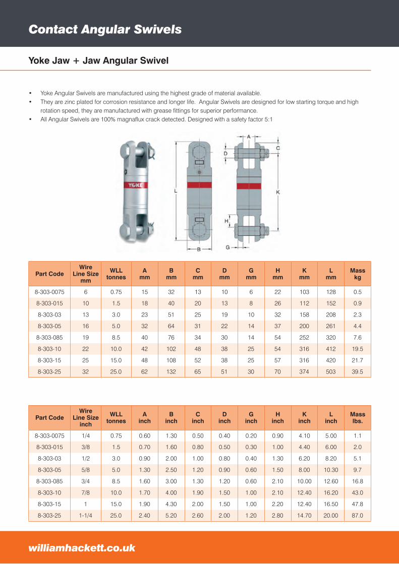
Contact Angular Swivels
williamhackett.co.uk
Yoke Jaw + Jaw Angular Swivel
Part CodeWire
Line Sizemm
WLLtonnes
Amm
Bmm
Cmm
Dmm
Gmm
Hmm
Kmm
Lmm
Masskg
8-303-0075 6 0.75 15 32 13 10 6 22 103 128 0.5
8-303-015 10 1.5 18 40 20 13 8 26 112 152 0.9
8-303-03 13 3.0 23 51 25 19 10 32 158 208 2.3
8-303-05 16 5.0 32 64 31 22 14 37 200 261 4.4
8-303-085 19 8.5 40 76 34 30 14 54 252 320 7.6
8-303-10 22 10.0 42 102 48 38 25 54 316 412 19.5
8-303-15 25 15.0 48 108 52 38 25 57 316 420 21.7
8-303-25 32 25.0 62 132 65 51 30 70 374 503 39.5
Contact Angular Swivels
williamhackett.co.uk
Contact Angular Swivels
williamhackett.co.uk
Contact Angular Swivels
williamhackett.co.uk
• Yoke Angular Swivels are manufactured using the highest grade of material available.• They are zinc plated for corrosion resistance and longer life. Angular Swivels are designed for low starting torque and high
rotation speed, they are manufactured with grease fittings for superior performance.• All Angular Swivels are 100% magnaflux crack detected. Designed with a safety factor 5:1
Part CodeWire
Line Sizeinch
WLLtonnes
Ainch
Binch
Cinch
Dinch
Ginch
Hinch
Kinch
Linch
Masslbs.
8-303-0075 1/4 0.75 0.60 1.30 0.50 0.40 0.20 0.90 4.10 5.00 1.1
8-303-015 3/8 1.5 0.70 1.60 0.80 0.50 0.30 1.00 4.40 6.00 2.0
8-303-03 1/2 3.0 0.90 2.00 1.00 0.80 0.40 1.30 6.20 8.20 5.1
8-303-05 5/8 5.0 1.30 2.50 1.20 0.90 0.60 1.50 8.00 10.30 9.7
8-303-085 3/4 8.5 1.60 3.00 1.30 1.20 0.60 2.10 10.00 12.60 16.8
8-303-10 7/8 10.0 1.70 4.00 1.90 1.50 1.00 2.10 12.40 16.20 43.0
8-303-15 1 15.0 1.90 4.30 2.00 1.50 1.00 2.20 12.40 16.50 47.8
8-303-25 1-1/4 25.0 2.40 5.20 2.60 2.00 1.20 2.80 14.70 20.00 87.0
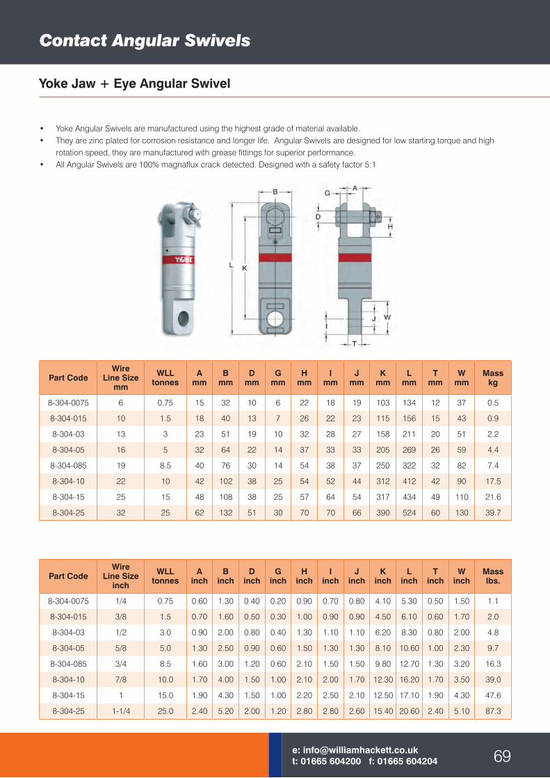
Yoke Jaw + Eye Angular Swivel
Contact Angular Swivels
• Yoke Angular Swivels are manufactured using the highest grade of material available.• They are zinc plated for corrosion resistance and longer life. Angular Swivels are designed for low starting torque and high
rotation speed, they are manufactured with grease fittings for superior performance.• All Angular Swivels are 100% magnaflux crack detected. Designed with a safety factor 5:1
Part CodeWire
Line Sizeinch
WLLtonnes
Ainch
Binch
Dinch
Ginch
Hinch
Iinch
Jinch
Kinch
Linch
Tinch
Winch
Masslbs.
8-304-0075 1/4 0.75 0.60 1.30 0.40 0.20 0.90 0.70 0.80 4.10 5.30 0.50 1.50 1.1
8-304-015 3/8 1.5 0.70 1.60 0.50 0.30 1.00 0.90 0.90 4.50 6.10 0.60 1.70 2.0
8-304-03 1/2 3.0 0.90 2.00 0.80 0.40 1.30 1.10 1.10 6.20 8.30 0.80 2.00 4.8
8-304-05 5/8 5.0 1.30 2.50 0.90 0.60 1.50 1.30 1.30 8.10 10.60 1.00 2.30 9.7
8-304-085 3/4 8.5 1.60 3.00 1.20 0.60 2.10 1.50 1.50 9.80 12.70 1.30 3.20 16.3
8-304-10 7/8 10.0 1.70 4.00 1.50 1.00 2.10 2.00 1.70 12.30 16.20 1.70 3.50 39.0
8-304-15 1 15.0 1.90 4.30 1.50 1.00 2.20 2.50 2.10 12.50 17.10 1.90 4.30 47.6
8-304-25 1-1/4 25.0 2.40 5.20 2.00 1.20 2.80 2.80 2.60 15.40 20.60 2.40 5.10 87.3
69e: [email protected]: 01665 604200 f: 01665 604204
Part CodeWire
Line Sizemm
WLLtonnes
Amm
Bmm
Dmm
Gmm
Hmm
Imm
Jmm
Kmm
Lmm
Tmm
Wmm
Masskg
8-304-0075 6 0.75 15 32 10 6 22 18 19 103 134 12 37 0.5
8-304-015 10 1.5 18 40 13 7 26 22 23 115 156 15 43 0.9
8-304-03 13 3 23 51 19 10 32 28 27 158 211 20 51 2.2
8-304-05 16 5 32 64 22 14 37 33 33 205 269 26 59 4.4
8-304-085 19 8.5 40 76 30 14 54 38 37 250 322 32 82 7.4
8-304-10 22 10 42 102 38 25 54 52 44 312 412 42 90 17.5
8-304-15 25 15 48 108 38 25 57 64 54 317 434 49 110 21.6
8-304-25 32 25 62 132 51 30 70 70 66 390 524 60 130 39.7
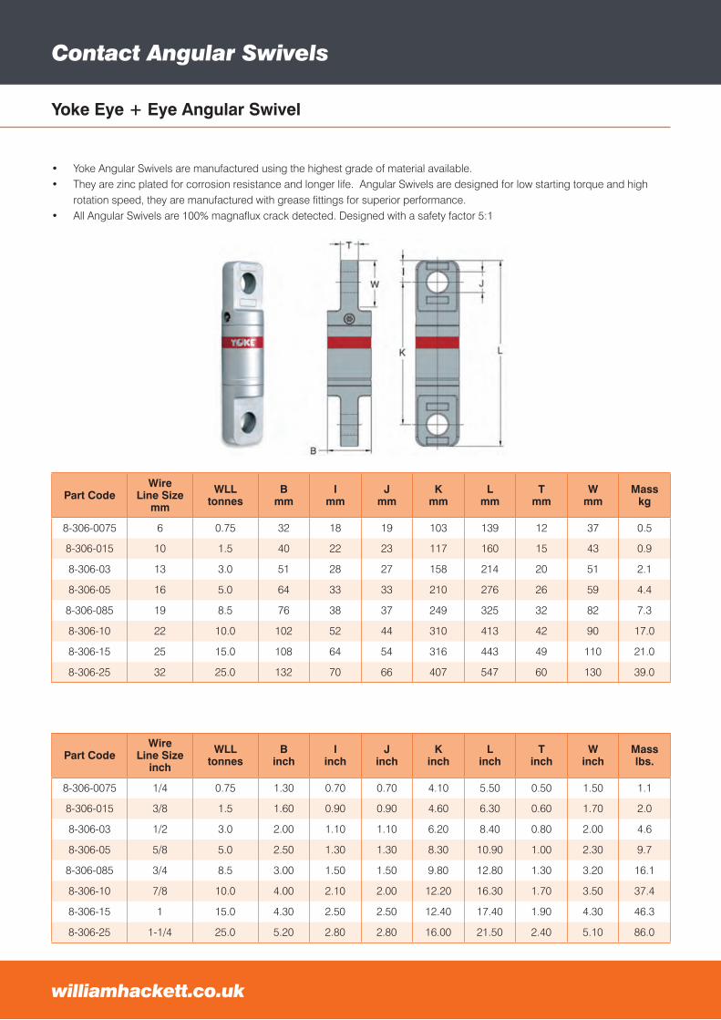
Yoke Eye + Eye Angular Swivel
Part CodeWire
Line Sizemm
WLLtonnes
Bmm
Imm
Jmm
Kmm
Lmm
Tmm
Wmm
Masskg
8-306-0075 6 0.75 32 18 19 103 139 12 37 0.5
8-306-015 10 1.5 40 22 23 117 160 15 43 0.9
8-306-03 13 3.0 51 28 27 158 214 20 51 2.1
8-306-05 16 5.0 64 33 33 210 276 26 59 4.4
8-306-085 19 8.5 76 38 37 249 325 32 82 7.3
8-306-10 22 10.0 102 52 44 310 413 42 90 17.0
8-306-15 25 15.0 108 64 54 316 443 49 110 21.0
8-306-25 32 25.0 132 70 66 407 547 60 130 39.0
Contact Angular Swivels
williamhackett.co.uk
Contact Angular Swivels
williamhackett.co.uk
• Yoke Angular Swivels are manufactured using the highest grade of material available.• They are zinc plated for corrosion resistance and longer life. Angular Swivels are designed for low starting torque and high
rotation speed, they are manufactured with grease fittings for superior performance.• All Angular Swivels are 100% magnaflux crack detected. Designed with a safety factor 5:1
Part CodeWire
Line Sizeinch
WLLtonnes
Binch
Iinch
Jinch
Kinch
Linch
Tinch
Winch
Masslbs.
8-306-0075 1/4 0.75 1.30 0.70 0.70 4.10 5.50 0.50 1.50 1.1
8-306-015 3/8 1.5 1.60 0.90 0.90 4.60 6.30 0.60 1.70 2.0
8-306-03 1/2 3.0 2.00 1.10 1.10 6.20 8.40 0.80 2.00 4.6
8-306-05 5/8 5.0 2.50 1.30 1.30 8.30 10.90 1.00 2.30 9.7
8-306-085 3/4 8.5 3.00 1.50 1.50 9.80 12.80 1.30 3.20 16.1
8-306-10 7/8 10.0 4.00 2.10 2.00 12.20 16.30 1.70 3.50 37.4
8-306-15 1 15.0 4.30 2.50 2.50 12.40 17.40 1.90 4.30 46.3
8-306-25 1-1/4 25.0 5.20 2.80 2.80 16.00 21.50 2.40 5.10 86.0

71e: [email protected]: 01665 604200 f: 01665 604204
William Hackett Sling App
The first ever free sling app forChain slings
Unsure of sling leg length required for lifting operation? Let the app use the trigonometry to work out thecorrect leg length.
Get the quote sent
straight to your
email address with
the spec sheet
attached and forward
it on to your client
within minutes!
Compatible on the following mobile devices: Apple, Android and WindowsWeb app also available.
How it works:• Create a free account and log in• Select number of legs• Input the weight of the load to be lifted• Input the leg length or state the distance between the lifting points to let the
app work out leg length and head room required.• Select the termination fittings• View your sling and hit submit quote.• Your quote will then be emailed to you instantly with a spec sheet attached
To put this Web App on your website free of charge, please contact Josh on01665 604200.
A personalised branded version of this App can be created but a charge will be applicable.
Check out our web app at:whackett.hippocreative.com/login.php
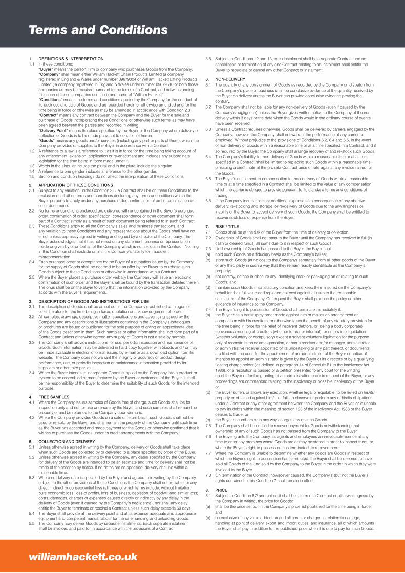
Terms and Conditions
1. DEFINITIONS & INTERPRETATION1.1 In these conditions: “Buyer” means the person, firm or company who purchases Goods from the Company. “Company” shall mean either William Hackett Chain Products Limited (a company registered in England & Wales under number 09679024 or William Hackett Lifting Products Limited ( a company registered in England & Wales under number 09679580 or both those companies as may be required pursuant to the terms of a Contract, and notwithstanding that each of those companies use the brand name of “William Hackett”. “Conditions” means the terms and conditions applied by the Company for the conduct of its business and sale of Goods and as recorded herein or otherwise amended and for the time being in force or otherwise as may be amended in accordance with Condition 2.3 “Contract” means any contract between the Company and the Buyer for the sale and purchase of Goods incorporating these Conditions or otherwise such terms as may have been agreed between the parties and recorded in writing. “Delivery Point” means the place specified by the Buyer or the Company where delivery or collection of Goods is to be made pursuant to condition 4 herein. “Goods” means any goods and/or services (including any part or parts of them), which the Company provides or supplies to the Buyer in accordance with a Contract. 1.2 A reference to a law is a reference to it as it is in force for the time being taking account of any amendment, extension, application or re-enactment and includes any subordinate legislation for the time being in force made under it.1.3 Words in the singular include the plural and in the plural include the singular.1.4 A reference to one gender includes a reference to the other gender.1.5 Section and condition headings do not affect the interpretation of these Conditions.
2. APPLICATION OF THESE CONDITIONS 2.1 Subject to any variation under Condition 2.3, a Contract shall be on these Conditions to the exclusion of all other terms and conditions (including any terms or conditions which the Buyer purports to apply under any purchase order, confirmation of order, specification or other document).2.2 No terms or conditions endorsed on, delivered with or contained in the Buyer’s purchase order, confirmation of order, specification, correspondence or other document shall form part of a Contract simply as a result of such document being referred to in such Contract.2.3 These Conditions apply to all the Company’s sales and business transactions, and any variation to these Conditions and any representations about the Goods shall have no effect unless expressly agreed in writing and signed by a director of the Company. The Buyer acknowledges that it has not relied on any statement, promise or representation made or given by or on behalf of the Company which is not set out in the Contract. Nothing in this Condition shall exclude or limit the Company’s liability for fraudulent misrepresentation.2.4 Each purchase order or acceptance by the Buyer of a quotation issued by the Company for the supply of Goods shall be deemed to be an offer by the Buyer to purchase such Goods subject to these Conditions or otherwise in accordance with a Contract.2.5 Where the Buyer places a purchase order verbally the Company will issue an electronic confirmation of such order and the Buyer shall be bound by the transaction detailed therein. The onus shall be on the Buyer to verify that the information provided by the Company accords with the Buyer’s requirements.
3. DESCRIPTION OF GOODS AND INSTRUCTIONS FOR USE3.1 The description of Goods shall be as set out in the Company’s published catalogue or other literature for the time being in force, quotation or acknowledgement of order.3.2 All samples, drawings, descriptive matter, specifications and advertising issued by the Company and any descriptions or illustrations contained in the Company’s catalogues or brochures are issued or published for the sole purpose of giving an approximate idea of the Goods described in them. Such samples or other information shall not form part of a Contract and unless otherwise agreed any supply of Goods is not a sale by sample.3.3 The Company shall provide instructions for use, periodic inspection and maintenance of Goods. Such information may be delivered in hard copy together with Goods and / or may be made available in electronic format issued by e-mail or as a download option from its website. The Company does not warrant the integrity or accuracy of product design, performance, use, or periodic inspection or maintenance information provided by its suppliers or other third parties.3.4 Where the Buyer intends to incorporate Goods supplied by the Company into a product or system to be assembled or manufactured by the Buyer or customers of the Buyer, it shall be the responsibility of the Buyer to determine the suitability of such Goods for the intended purpose.
4. FREE SAMPLES4.1 Where the Company issues samples of Goods free of charge, such Goods shall be for inspection only and not for use or re-sale by the Buyer, and such samples shall remain the property of and be returned to the Company upon demand.4.2 Where the Company provides Goods on a sale or return basis, such Goods shall not be used or re-sold by the Buyer and shall remain the property of the Company until such time as the Buyer has accepted and made payment for the Goods or otherwise confirmed that it wishes to purchase the Goods under its credit arrangements with the Company.
5. COLLECTION AND DELIVERY5.1 Unless otherwise agreed in writing by the Company, delivery of Goods shall take place when such Goods are collected by or delivered to a place specified by order of the Buyer.5.2 Unless otherwise agreed in writing by the Company, any dates specified by the Company for delivery of the Goods are intended to be an estimate and time for delivery shall not be made of the essence by notice. If no dates are so specified, delivery shall be within a reasonable time.5.3 Where no delivery date is specified by the Buyer and agreed to in writing by the Company, subject to the other provisions of these Conditions the Company shall not be liable for any direct, indirect or consequential loss (all three of which terms include, without limitation, pure economic loss, loss of profits, loss of business, depletion of goodwill and similar loss), costs, damages, charges or expenses caused directly or indirectly by any delay in the delivery of Goods (even if caused by the Company’s negligence), nor shall any delay entitle the Buyer to terminate or rescind a Contract unless such delay exceeds 60 days.5.4 The Buyer shall provide at the delivery point and at its expense adequate and appropriate equipment and competent manual labour for the safe handling and unloading Goods.5.5 The Company may deliver Goods by separate instalments. Each separate instalment shall be invoiced and paid for in accordance with the provisions of a Contract.
5.6 Subject to Conditions 12 and 13, each instalment shall be a separate Contract and no cancellation or termination of any one Contract relating to an instalment shall entitle the Buyer to repudiate or cancel any other Contract or instalment.
6. NON-DELIVERY6.1 The quantity of any consignment of Goods as recorded by the Company on dispatch from the Company’s place of business shall be conclusive evidence of the quantity received by the Buyer on delivery unless the Buyer can provide conclusive evidence proving the contrary.6.2 The Company shall not be liable for any non-delivery of Goods (even if caused by the Company’s negligence) unless the Buyer gives written notice to the Company of the non delivery within 3 days of the date when the Goods would in the ordinary course of events have been received.6.3 Unless a Contract requires otherwise, Goods shall be delivered by carriers engaged by the Company, however, the Company shall not warrant the performance of any carrier so employed. Without prejudice to the provisions of Conditions 6.2, 6.4 and 6.5, in the event of non-delivery of Goods within a reasonable time or at a time specified in a Contract, and if so required by the Buyer, the Company shall arrange recovery of and re-stock such Goods. 6.4 The Company’s liability for non-delivery of Goods within a reasonable time or at a time specified in a Contract shall be limited to replacing such Goods within a reasonable time or issuing a credit note at the pro rata Contract price or rate against any invoice raised for the Goods.6.5 The Buyer’s entitlement to compensation for non-delivery of Goods within a reasonable time or at a time specified in a Contract shall be limited to the value of any compensation which the carrier is obliged to provide pursuant to its standard terms and conditions of trading.6.6 If the Company incurs a loss or additional expense as a consequence of any abortive delivery, re-stocking and storage, or re-delivery of Goods due to the unwillingness or inability of the Buyer to accept delivery of such Goods, the Company shall be entitled to recover such loss or expense from the Buyer.
7. RISK / TITLE7.1 Goods shall be at the risk of the Buyer from the time of delivery or collection.7.2 Ownership of Goods shall not pass to the Buyer until the Company has received in full (in cash or cleared funds) all sums due to it in respect of such Goods.7.3 Until ownership of Goods has passed to the Buyer, the Buyer shall:(a) hold such Goods on a fiduciary basis as the Company’s bailee;(b) store such Goods (at no cost to the Company) separately from all other goods of the Buyer or any third party in such a way that they remain readily identifiable as the Company’s property;(c) not destroy, deface or obscure any identifying mark or packaging on or relating to such Goods; and(d) maintain such Goods in satisfactory condition and keep them insured on the Company’s behalf for their full value and replacement cost against all risks to the reasonable satisfaction of the Company. On request the Buyer shall produce the policy or other evidence of insurance to the Company.7.4 The Buyer’s right to possession of Goods shall terminate immediately if:(a) the Buyer has a bankruptcy order made against him or makes an arrangement or composition with his creditors, or otherwise takes the benefit of any statutory provision for the time being in force for the relief of insolvent debtors, or (being a body corporate) convenes a meeting of creditors (whether formal or informal), or enters into liquidation (whether voluntary or compulsory) except a solvent voluntary liquidation for the purpose only of reconstruction or amalgamation, or has a receiver and/or manager, administrator or administrative receiver appointed of its undertaking or any part thereof, or documents are filed with the court for the appointment of an administrator of the Buyer or notice of intention to appoint an administrator is given by the Buyer or its directors or by a qualifying floating charge holder (as defined in paragraph 14 of Schedule B1 to the Insolvency Act 1986), or a resolution is passed or a petition presented to any court for the winding up of the Buyer or for the granting of an administration order in respect of the Buyer, or any proceedings are commenced relating to the insolvency or possible insolvency of the Buyer; or(b) the Buyer suffers or allows any execution, whether legal or equitable, to be levied on his/its property or obtained against him/it, or fails to observe or perform any of his/its obligations under a Contract or any other agreement between the Company and the Buyer, or is unable to pay its debts within the meaning of section 123 of the Insolvency Act 1986 or the Buyer ceases to trade; or(c) the Buyer encumbers or in any way charges any of such Goods.7.5 The Company shall be entitled to recover payment for Goods notwithstanding that ownership of any of such Goods has not passed from the Company to the Buyer.7.6 The Buyer grants the Company, its agents and employees an irrevocable licence at any time to enter any premises where Goods are or may be stored in order to inspect them, or, where the Buyer’s right to possession has terminated, to recover them.7.7 Where the Company is unable to determine whether any goods are Goods in respect of which the Buyer’s right to possession has terminated, the Buyer shall be deemed to have sold all Goods of the kind sold by the Company to the Buyer in the order in which they were invoiced to the Buyer.7.8 On termination of the Contract, howsoever caused, the Company’s (but not the Buyer’s) rights contained in this Condition 7 shall remain in effect.
8. PRICE8.1 Subject to Condition 8.2 and unless it shall be a term of a Contract or otherwise agreed by the Company in writing, the price for Goods: (a) shall be the price set out in the Company’s price list published for the time being in force; and(b) be exclusive of any value added tax and all costs or charges in relation to carriage, handling at point of delivery, export and import duties, and insurance, all of which amounts the Buyer shall pay in addition to the published price when it is due to pay for such Goods.
williamhackett.co.ukwilliamhackett.co.uk
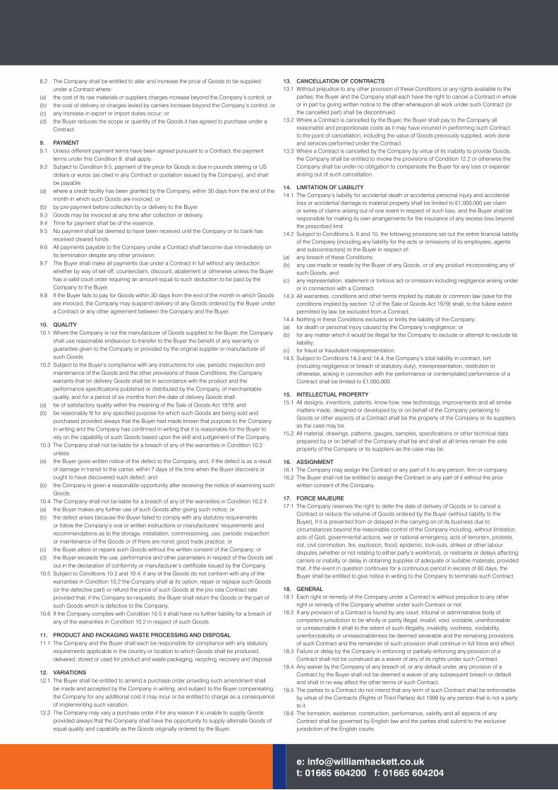
8.2 The Company shall be entitled to alter and increase the price of Goods to be supplied under a Contract where:(a) the cost of its raw materials or suppliers charges increase beyond the Company’s control; or(b) the cost of delivery or charges levied by carriers increase beyond the Company’s control; or (c) any increase in export or import duties occur; or(d) the Buyer reduces the scope or quantity of the Goods it has agreed to purchase under a Contract.
9. PAYMENT9.1 Unless different payment terms have been agreed pursuant to a Contract, the payment terms under this Condition 9. shall apply.9.2 Subject to Condition 9.5, payment of the price for Goods is due in pounds sterling or US dollars or euros (as cited in any Contract or quotation issued by the Company), and shall be payable:(a) where a credit facility has been granted by the Company, within 30 days from the end of the month in which such Goods are invoiced; or (b) by pre-payment before collection by or delivery to the Buyer. 9.3 Goods may be invoiced at any time after collection or delivery.9.4 Time for payment shall be of the essence.9.5 No payment shall be deemed to have been received until the Company or its bank has received cleared funds.9.6 All payments payable to the Company under a Contract shall become due immediately on its termination despite any other provision.9.7 The Buyer shall make all payments due under a Contract in full without any deduction whether by way of set-off, counterclaim, discount, abatement or otherwise unless the Buyer has a valid court order requiring an amount equal to such deduction to be paid by the Company to the Buyer.9.8 If the Buyer fails to pay for Goods within 30 days from the end of the month in which Goods are invoiced, the Company may suspend delivery of any Goods ordered by the Buyer under a Contract or any other agreement between the Company and the Buyer.
10. QUALITY10.1 Where the Company is not the manufacturer of Goods supplied to the Buyer, the Company shall use reasonable endeavour to transfer to the Buyer the benefit of any warranty or guarantee given to the Company or provided by the original supplier or manufacturer of such Goods.10.2 Subject to the Buyer’s compliance with any instructions for use, periodic inspection and maintenance of the Goods and the other provisions of these Conditions, the Company warrants that on delivery Goods shall be in accordance with the product and the performance specifications published or distributed by the Company, of merchantable quality, and for a period of six months from the date of delivery Goods shall: (a) be of satisfactory quality within the meaning of the Sale of Goods Act 1979; and(b) be reasonably fit for any specified purpose for which such Goods are being sold and purchased provided always that the Buyer had made known that purpose to the Company in writing and the Company has confirmed in writing that it is reasonable for the Buyer to rely on the capability of such Goods based upon the skill and judgement of the Company.10.3 The Company shall not be liable for a breach of any of the warranties in Condition 10.2 unless:(a) the Buyer gives written notice of the defect to the Company, and, if the defect is as a result of damage in transit to the carrier, within 7 days of the time when the Buyer discovers or ought to have discovered such defect; and(b) the Company is given a reasonable opportunity after receiving the notice of examining such Goods.10.4 The Company shall not be liable for a breach of any of the warranties in Condition 10.2 if:(a) the Buyer makes any further use of such Goods after giving such notice; or(b) the defect arises because the Buyer failed to comply with any statutory requirements or follow the Company’s oral or written instructions or manufacturers’ requirements and recommendations as to the storage, installation, commissioning, use, periodic inspection or maintenance of the Goods or (if there are none) good trade practice; or(c) the Buyer alters or repairs such Goods without the written consent of the Company; or(d) the Buyer exceeds the use, performance and other parameters in respect of the Goods set out in the declaration of conformity or manufacturer’s certificate issued by the Company.10.5 Subject to Conditions 10.3 and 10.4, if any of the Goods do not conform with any of the warranties in Condition 10.2 the Company shall at its option, repair or replace such Goods (or the defective part) or refund the price of such Goods at the pro rata Contract rate provided that, if the Company so requests, the Buyer shall return the Goods or the part of such Goods which is defective to the Company.10.6 If the Company complies with Condition 10.5 it shall have no further liability for a breach of any of the warranties in Condition 10.2 in respect of such Goods.
11. PRODUCT AND PACKAGING WASTE PROCESSING AND DISPOSAL11.1 The Company and the Buyer shall each be responsible for compliance with any statutory requirements applicable in the country or location to which Goods shall be produced, delivered, stored or used for product and waste packaging, recycling, recovery and disposal.
12. VARIATIONS 12.1 The Buyer shall be entitled to amend a purchase order providing such amendment shall be made and accepted by the Company in writing, and subject to the Buyer compensating the Company for any additional cost it may incur or be entitled to charge as a consequence of implementing such variation.12.2 The Company may vary a purchase order if for any reason it is unable to supply Goods provided always that the Company shall have the opportunity to supply alternate Goods of equal quality and capability as the Goods originally ordered by the Buyer.
13. CANCELLATION OF CONTRACTS13.1 Without prejudice to any other provision of these Conditions or any rights available to the parties, the Buyer and the Company shall each have the right to cancel a Contract in whole or in part by giving written notice to the other whereupon all work under such Contract (or the cancelled part) shall be discontinued. 13.2 Where a Contract is cancelled by the Buyer, the Buyer shall pay to the Company all reasonable and proportionate costs as it may have incurred in performing such Contract to the point of cancellation, including the value of Goods previously supplied, work done and services performed under the Contract.13.3 Where a Contract is cancelled by the Company by virtue of its inability to provide Goods, the Company shall be entitled to invoke the provisions of Condition 12.2 or otherwise the Company shall be under no obligation to compensate the Buyer for any loss or expense arising out of such cancellation.
14. LIMITATION OF LIABILITY14.1 The Company’s liability for accidental death or accidental personal injury and accidental loss or accidental damage to material property shall be limited to £1,000,000 per claim or series of claims arising out of one event in respect of such loss, and the Buyer shall be responsible for making its own arrangements for the insurance of any excess loss beyond the prescribed limit.14.2 Subject to Conditions 5, 6 and 10, the following provisions set out the entire financial liability of the Company (including any liability for the acts or omissions of its employees, agents and subcontractors) to the Buyer in respect of:(a) any breach of these Conditions;(b) any use made or resale by the Buyer of any Goods, or of any product incorporating any of such Goods; and(c) any representation, statement or tortious act or omission including negligence arising under or in connection with a Contract.14.3 All warranties, conditions and other terms implied by statute or common law (save for the conditions implied by section 12 of the Sale of Goods Act 1979) shall, to the fullest extent permitted by law, be excluded from a Contract.14.4 Nothing in these Conditions excludes or limits the liability of the Company:(a) for death or personal injury caused by the Company’s negligence; or(b) for any matter which it would be illegal for the Company to exclude or attempt to exclude its liability;(c) for fraud or fraudulent misrepresentation.14.5 Subject to Conditions 14.3 and 14.4, the Company’s total liability in contract, tort (including negligence or breach of statutory duty), misrepresentation, restitution or otherwise, arising in connection with the performance or contemplated performance of a Contract shall be limited to £1,000,000.
15. INTELLECTUAL PROPERTY15.1 All designs, inventions, patents, know how, new technology, improvements and all similar matters made, designed or developed by or on behalf of the Company pertaining to Goods or other aspects of a Contract shall be the property of the Company or its suppliers as the case may be.15.2 All material, drawings, patterns, gauges, samples, specifications or other technical data prepared by or on behalf of the Company shall be and shall at all times remain the sole property of the Company or its suppliers as the case may be.
16. ASSIGNMENT16.1 The Company may assign the Contract or any part of it to any person, firm or company.16.2 The Buyer shall not be entitled to assign the Contract or any part of it without the prior written consent of the Company.
17. FORCE MAJEURE17.1 The Company reserves the right to defer the date of delivery of Goods or to cancel a Contract or reduce the volume of Goods ordered by the Buyer (without liability to the Buyer), if it is prevented from or delayed in the carrying on of its business due to circumstances beyond the reasonable control of the Company including, without limitation, acts of God, governmental actions, war or national emergency, acts of terrorism, protests, riot, civil commotion, fire, explosion, flood, epidemic, lock-outs, strikes or other labour disputes (whether or not relating to either party’s workforce), or restraints or delays affecting carriers or inability or delay in obtaining supplies of adequate or suitable materials, provided that, if the event in question continues for a continuous period in excess of 60 days, the Buyer shall be entitled to give notice in writing to the Company to terminate such Contract.
18. GENERAL18.1 Each right or remedy of the Company under a Contract is without prejudice to any other right or remedy of the Company whether under such Contract or not.18.2 If any provision of a Contract is found by any court, tribunal or administrative body of competent jurisdiction to be wholly or partly illegal, invalid, void, voidable, unenforceable or unreasonable it shall to the extent of such illegality, invalidity, voidness, voidability, unenforceability or unreasonableness be deemed severable and the remaining provisions of such Contract and the remainder of such provision shall continue in full force and effect.18.3 Failure or delay by the Company in enforcing or partially enforcing any provision of a Contract shall not be construed as a waiver of any of its rights under such Contract.18.4 Any waiver by the Company of any breach of, or any default under, any provision of a Contract by the Buyer shall not be deemed a waiver of any subsequent breach or default and shall in no way affect the other terms of such Contract.18.5 The parties to a Contract do not intend that any term of such Contract shall be enforceable by virtue of the Contracts (Rights of Third Parties) Act 1999 by any person that is not a party to it.18.6 The formation, existence, construction, performance, validity and all aspects of any Contract shall be governed by English law and the parties shall submit to the exclusive jurisdiction of the English courts.
e: [email protected]: 01665 604200 f: 01665 604204

t: 01665 604200 f: 01665 604204
William Hackett Lifting Products LimitedOak Drive, Lionheart Enterprise Park
Alnwick, NorthumberlandUnited Kingdom
NE66 2EU
William Hackett Chain Products LimitedMaypole Fields, Cradley
Halesowen, West MidlandsUnited Kingdom
B63 2QE


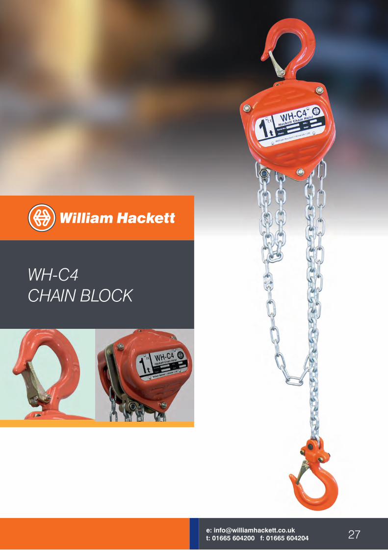
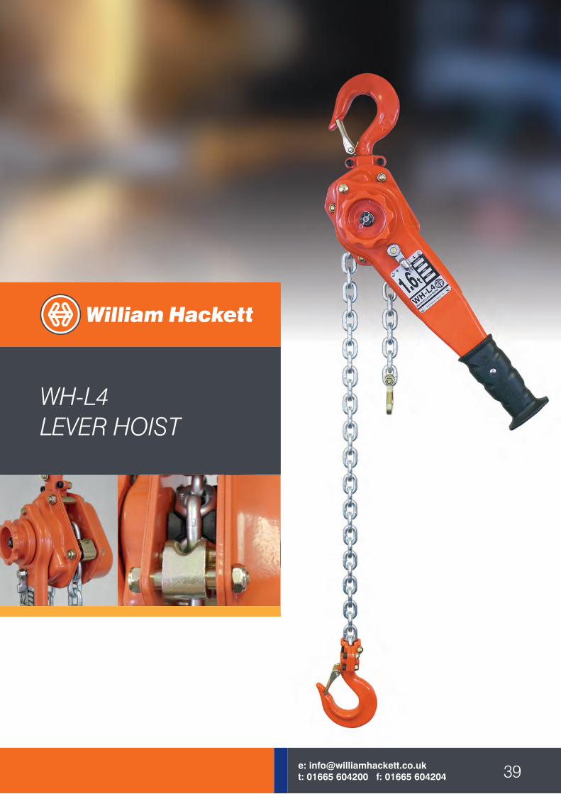
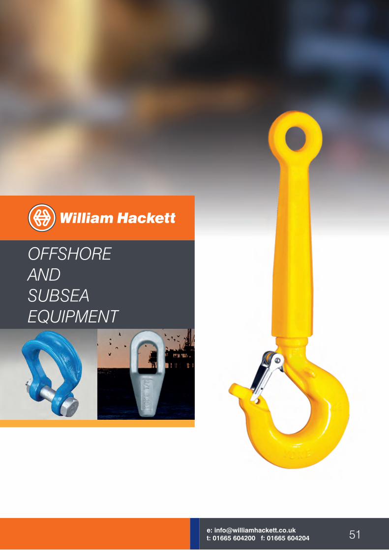


![Plato's timaeus [hackett]](https://img.pdfslide.us/doc/110x75/579057061a28ab900c9ba721/platos-timaeus-hackett.jpg)


![Hackett ITResume SEPT01[2]](https://img.pdfslide.us/doc/110x75/589b84101a28ab8e5b8b6479/hackett-itresume-sept012.jpg)